P910 Working Instructions by Adalbertio
62
Working Instruction, Mechanical 3/00021-1/FEA 209 544/90 A Sony Ericsson Mobile Communications AB Working Instruction, Mechanical Applicable for P910a, P910c, and P910i Contents 1 General.............................................................................................................................2 2 Disassembly ..................................................... .................. .................. ............................ 2 3 Reassembly .......................................................................................... .................. .......... 9 4 Replacement of Mechanical Parts ........................................................................ ....... 19 4.1 Front Cover......................................................................................................19 4.2 Front Speaker, Speaker Holder, and Speaker Cloth ........................................ 21 4.3 RF Port Cover..................................................................................................23 4.4 Batte ry Cove r ........................................................................................... .......23 4.5 Display.............................................................................................................23 4.6 Flip Assembly..................................................................................................24 4.7 Flip Hinge Cover ............................................................................................. 24 4.8 Camera Module ............................................................................................... 24 4.9 Back Cover ...................................................................................................... 26 4.10 Internet Key.....................................................................................................39 4.11 Camera Key.....................................................................................................39 4.12 Power On/Off Key...........................................................................................39 4.13 Camera Gasket .......................................................................................... ......40 4.14 Vibra tor ...........................................................................................................41 4.15 Rear Speaker, Holder, and Cloth.....................................................................41 4.16 Audio Jack and Audio Jack Cover .................................................................. 41 4.17 Microphone Assembly and Microphone Cloth ............................................... 41 4.18 Jog Dial............................................................................................................43 4.19 Anten na Assembly ..........................................................................................46 4.20 Memory Stick Cover ....................................................................................... 50 4.21 Camera Window Assembly.............................................................................50 4.22 Camera/Internet Key Switch ........................................................................... 51 4.23 Stylus Holder...................................................................................................55 4.24 Water Indicator Label......................................................................................60 4.25 Label Replacement .......................................................................................... 61 5 Revision History............................................................................................................62
-
Upload
renato-ames -
Category
Documents
-
view
219 -
download
0
Transcript of P910 Working Instructions by Adalbertio

8/4/2019 P910 Working Instructions by Adalbertio
http://slidepdf.com/reader/full/p910-working-instructions-by-adalbertio 1/62
Working Instruction, Mechanical
3/00021-1/FEA 209 544/90 A
Sony Ericsson Mobile Communications AB
Working Instruction, MechanicalApplicable for P910a, P910c, and P910i
Contents
1 General.............................................................................................................................2
2 Disassembly ..................................................................................................................... 2
3 Reassembly ...................................................................................................................... 9
4 Replacement of Mechanical Parts ............................................................................... 19
4.1 Front Cover......................................................................................................19 4.2 Front Speaker, Speaker Holder, and Speaker Cloth ........................................ 21 4.3 RF Port Cover..................................................................................................23 4.4 Battery Cover ..................................................................................................23 4.5 Display.............................................................................................................23 4.6 Flip Assembly..................................................................................................24 4.7 Flip Hinge Cover ............................................................................................. 24 4.8 Camera Module ............................................................................................... 24 4.9 Back Cover ...................................................................................................... 26 4.10 Internet Key.....................................................................................................39 4.11 Camera Key.....................................................................................................39 4.12 Power On/Off Key...........................................................................................39 4.13 Camera Gasket ................................................................................................40 4.14 Vibrator ...........................................................................................................41 4.15 Rear Speaker, Holder, and Cloth.....................................................................41 4.16 Audio Jack and Audio Jack Cover .................................................................. 41 4.17 Microphone Assembly and Microphone Cloth ............................................... 41 4.18 Jog Dial............................................................................................................43 4.19 Antenna Assembly ..........................................................................................46 4.20 Memory Stick Cover ....................................................................................... 50 4.21 Camera Window Assembly.............................................................................50 4.22 Camera/Internet Key Switch ...........................................................................51 4.23 Stylus Holder...................................................................................................55 4.24 Water Indicator Label......................................................................................60 4.25 Label Replacement .......................................................................................... 61
5 Revision History............................................................................................................62
8/4/2019 P910 Working Instructions by Adalbertio
http://slidepdf.com/reader/full/p910-working-instructions-by-adalbertio 2/62
Working Instruction, Mechanical
3/00021-1/FEA 209 544/90 A
Sony Ericsson Mobile Communications AB
2(62)
1 General
When handling this product take care to keep all surfaces clean of dirt, dust, debris, and hand
grease. Use appropriate ESD precautions when working on this product. The use of finger cots or
gloves, an ESD mat, and an ESD wrist strap are required at minimum.
2 Disassembly
Tools:
• Torque screwdriver • Orange stick
• JCIS No. 0 bit • Nylon pointer
• Style 2A ESD-safe tweezers (Blunt Tip) • Front opening tool
NOTE! Whenever the phrase “pry tool” is used, a nylon pointer, an orange stick, or a front
opening tool may be used, depending on the user’s preference.
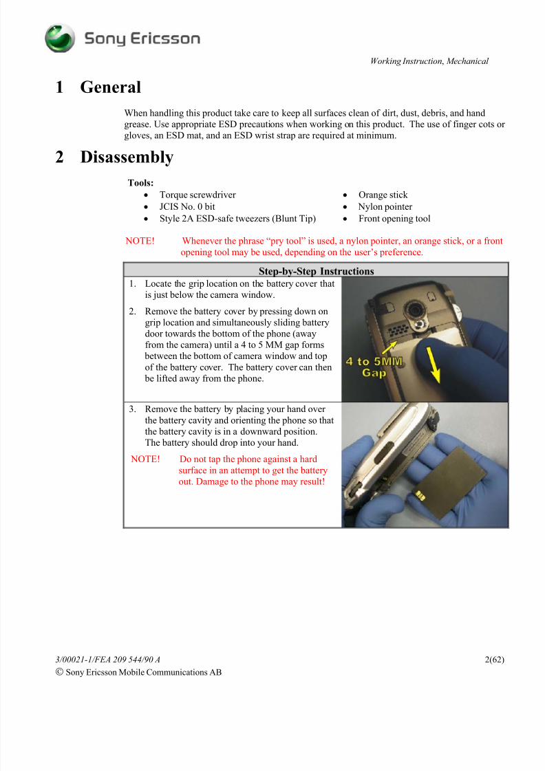
Step-by-Step Instructions1. Locate the grip location on the battery cover that
is just below the camera window.
2. Remove the battery cover by pressing down on
grip location and simultaneously sliding battery
door towards the bottom of the phone (away
from the camera) until a 4 to 5 MM gap forms
between the bottom of camera window and top
of the battery cover. The battery cover can then
be lifted away from the phone.
3. Remove the battery by placing your hand over
the battery cavity and orienting the phone so that
the battery cavity is in a downward position.
The battery should drop into your hand.
NOTE! Do not tap the phone against a hard
surface in an attempt to get the battery
out. Damage to the phone may result!

8/4/2019 P910 Working Instructions by Adalbertio
http://slidepdf.com/reader/full/p910-working-instructions-by-adalbertio 3/62
Working Instruction, Mechanical
3/00021-1/FEA 209 544/90 A
Sony Ericsson Mobile Communications AB
3(62)
Step-by-Step Instructions
NOTE! Be careful not to scratch or scar the
phone or the flip hinge cover when
removing the flip hinge cover.
4. With the flip in the closed position, slide the flat
end of a pry tool under one of the accessible
corners of the flip hinge cover and rotate the pry
tool away from the system connector. The hinge
cover should start to separate from the phone
along the edge adjacent to the system connector.
5. Once you have got the separation of the flip
hinge cover started, work the pry tool along the
flip hinge cover’s separating edge to finish
releasing it from the phone.
6. Once the edge of the flip hinge cover is released
from the phone, lift the hinge cover’s free edge
up and out away from the phone as shown. The
flip hinge cover should easily slide out from
between the flip and the front cover when lifted
in the manner shown.
7. Using a torque driver with a JCIS No. 0 bit,
remove the two M1.4 x 3.5MM screws holding
the flip assembly.
NOTE! Do not reuse the screws that hold the
flip assembly in place.

8/4/2019 P910 Working Instructions by Adalbertio
http://slidepdf.com/reader/full/p910-working-instructions-by-adalbertio 4/62
Working Instruction, Mechanical
3/00021-1/FEA 209 544/90 A
Sony Ericsson Mobile Communications AB
4(62)
Step-by-Step Instructions8. Support the hinge joint by placing your finger on
the black portion of the hinge.
9. Then rotate the flip so that it forms a 90º angle
with the rest of the phone.
10. Remove your finger from the black portion of
the hinge and rotate the flip away from the
phone. While rotating the flip, it should come
free from the phone.
11. Orient the phone so that the side of the phone
with the camera is towards you and the end of
the phone with the system connector is the
bottom of the phone.
12. Insert the pointed end of the nylon pointer intosmall hole in the RF port cover and rotate thenylon pointer down towards the outer edge of the
phone. The RF port cover should lift from it
cavity.
13. Using a pair of tweezers, press inward on side of
the left side screw cover that is accessible from
the RF port opening. While applying inward
pressure on the left side screw cover, pry the
cover upward way from the phone.
14. Once the left side screw cover is loose, remove itfrom the phone.

8/4/2019 P910 Working Instructions by Adalbertio
http://slidepdf.com/reader/full/p910-working-instructions-by-adalbertio 5/62
Working Instruction, Mechanical
3/00021-1/FEA 209 544/90 A
Sony Ericsson Mobile Communications AB
5(62)
Step-by-Step Instructions
15. Using the pair of tweezers, press the tip of one of
the tweezers’ arms down into the notch in the
right side screw cover and pry the cover up out
of its cavity.
16. Once the sides of the right side screw cover are
accessible, lift it from the phone using the
tweezers.
NOTE! If the disassembly procedure is only
being preformed for the purpose of
removing the front cover, the following
two steps can be skipped. Otherwise the
following two steps need to be preformed before removing the front
cover.
17. If present, remove the memory stick.
18. If present, remove the SIM card.
19. Remove the four screws from the back cover
using a torque driver with a JCIS No. 0 bit.
NOTE! The two screws near the system
connector cannot be reused. The twoscrews near the camera window are self-
tapping screws and can be reused.

8/4/2019 P910 Working Instructions by Adalbertio
http://slidepdf.com/reader/full/p910-working-instructions-by-adalbertio 6/62
Working Instruction, Mechanical
3/00021-1/FEA 209 544/90 A
Sony Ericsson Mobile Communications AB
6(62)
Step-by-Step Instructions20. Starting at the end of the phone that contains the
system connector, work a pry tool in the seam
between the front and back covers and gently
twist the pry tool to separate the covers.
21. Once the separation of the front and back covers
is started at the bottom of the phone, move to
one of the seams that run along each side of the
phone where the front and back covers come
together. Using the flat end of a pry tool, gently
twist the pry tool to separate the front and back covers. As the seam opens up, switch from side
to side working the seam open by sliding the pry
tool down the seam and twisting. Continue
doing this back and forth along each side until
the seams are opened up on each side just passed
where the top of the display is located.
22. Remove the front cover by lifting up and rotating
it away from the end of the phone with the
system connector.

8/4/2019 P910 Working Instructions by Adalbertio
http://slidepdf.com/reader/full/p910-working-instructions-by-adalbertio 7/62
Working Instruction, Mechanical
3/00021-1/FEA 209 544/90 A
Sony Ericsson Mobile Communications AB
7(62)
Step-by-Step Instructions NOTE! The display is connected to the non-
accessible side of the circuit board.
Therefore the circuit board has to be
removed from the back cover before thedisplay can be disconnected from the
circuit board.
NOTE! Be careful not to damage the display or
its flex film while trying the remove
the circuit board from the back cover.
23. Lay a scrap front cover, external side up,adjacent to the side of the back cover that the
camera key is located on and rotate the display
so that it is laying on top of the scrap front cover.
24. Remove the two screws from the shielding can
using a torque driver with a JCIS No. 0 bit.
25. Then lift the shield can away from the circuit board.

8/4/2019 P910 Working Instructions by Adalbertio
http://slidepdf.com/reader/full/p910-working-instructions-by-adalbertio 8/62
Working Instruction, Mechanical
3/00021-1/FEA 209 544/90 A
Sony Ericsson Mobile Communications AB
8(62)
Step-by-Step Instructions26. There are 5 latches that hold the circuit board in
the back cover. To release the circuit board,
gently pry between the circuit board and the
back cover in the 4 locations indicated in theorder specified.
NOTE! Only pry as much as is needed to
release the latches!
NOTE! When prying in location 2 make not to
pry over the portion of the antenna that
is visible.
NOTE! Be careful not to damage the RF port
when prying to release the latches at
location 2.
27. Once the latches holding the circuit board are
released, slightly lift up the side of the circuit
board the display is adjacent to and using a pry
tool, carefully disconnect the flex connection of
the display from the circuit board. Then set the
display aside.
28. Once the display is removed, increase the size of
the opening between the circuit board and the
back cover and locate the jog dial flex film
connection.
29. Using a pry tool, carefully disconnect the flex
connection of the jog dial from the circuit board.

8/4/2019 P910 Working Instructions by Adalbertio
http://slidepdf.com/reader/full/p910-working-instructions-by-adalbertio 9/62
Working Instruction, Mechanical
3/00021-1/FEA 209 544/90 A
Sony Ericsson Mobile Communications AB
9(62)
Step-by-Step Instructions30. Then lift the circuit board away from the back
cover.
3 Reassembly
Tools:
• Torque screwdriver • Orange stick
• JCIS No. 0 bit • Nylon pointer
• Style 2A ESD-safe tweezers (Blunt Tip) • Front opening tool
NOTE! Whenever the phrase “pry tool” is used, a nylon pointer, an orange stick, or a front
opening tool may be used, depending on the user’s preference.
Step-by-Step Instructions NOTE! Make sure that the camera gasket is in
its correct position before proceeding so
that the circuit board fits correctly into
the back cover.
1. Lay the edge of the circuit board inside the edge
of the back cover so that the contact pads on the
board for audio jack are adjacent to the jack inthe back cover as shown.
8/4/2019 P910 Working Instructions by Adalbertio
http://slidepdf.com/reader/full/p910-working-instructions-by-adalbertio 10/62
Working Instruction, Mechanical
3/00021-1/FEA 209 544/90 A
Sony Ericsson Mobile Communications AB
10(62)
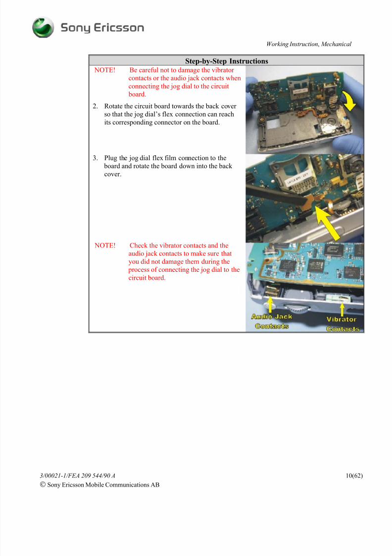
Step-by-Step Instructions NOTE! Be careful not to damage the vibrator
contacts or the audio jack contacts when
connecting the jog dial to the circuit
board.2. Rotate the circuit board towards the back cover
so that the jog dial’s flex connection can reach
its corresponding connector on the board.
3. Plug the jog dial flex film connection to the
board and rotate the board down into the back
cover.
NOTE! Check the vibrator contacts and the
audio jack contacts to make sure that
you did not damage them during the
process of connecting the jog dial to the
circuit board.

8/4/2019 P910 Working Instructions by Adalbertio
http://slidepdf.com/reader/full/p910-working-instructions-by-adalbertio 11/62
Working Instruction, Mechanical
3/00021-1/FEA 209 544/90 A
Sony Ericsson Mobile Communications AB
11(62)
Step-by-Step Instructions4. If a new display is being installed, mount the two
cushions shown onto the display as indicated.
5. If a new display is being installed, mount a
display spacer onto the edge of the display as
shown. If the old display is being reinstalled,verify that a display spacer is mounted onto the
edge of the display as indicated. If a display
spacer is not present, install one as shown.
8/4/2019 P910 Working Instructions by Adalbertio
http://slidepdf.com/reader/full/p910-working-instructions-by-adalbertio 12/62
Working Instruction, Mechanical
3/00021-1/FEA 209 544/90 A
Sony Ericsson Mobile Communications AB
12(62)
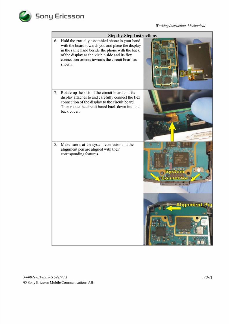
Step-by-Step Instructions6. Hold the partially assembled phone in your hand
with the board towards you and place the display
in the same hand beside the phone with the back
of the display as the visible side and its flexconnection orients towards the circuit board as
shown.
7. Rotate up the side of the circuit board that the
display attaches to and carefully connect the flex
connection of the display to the circuit board.
Then rotate the circuit board back down into the
back cover.
8. Make sure that the system connector and the
alignment pen are aligned with their
corresponding features.

8/4/2019 P910 Working Instructions by Adalbertio
http://slidepdf.com/reader/full/p910-working-instructions-by-adalbertio 13/62
Working Instruction, Mechanical
3/00021-1/FEA 209 544/90 A
Sony Ericsson Mobile Communications AB
13(62)
Step-by-Step Instructions9. Snap the circuit board into the back cover by
pressing the board in the 4 locations shown in
the order indicated so that 5 latches on the back
cover that hold the circuit board in place engage.
10. Place the shield can over the circuit board so that
the shield can matches up with the outline on the
circuit board.
11. Install two M1.4 x 4MM screws using a torque
of 7 N*cm in the two locations indicated.

8/4/2019 P910 Working Instructions by Adalbertio
http://slidepdf.com/reader/full/p910-working-instructions-by-adalbertio 14/62
Working Instruction, Mechanical
3/00021-1/FEA 209 544/90 A
Sony Ericsson Mobile Communications AB
14(62)
Step-by-Step Instructions12. Rotate the display so that it is laying on top of
the shield can.
NOTE! Hold the display in place while installed
the front cover so that the display does
not move around and put unnecessary
strain on the display’s flex film.
13. Work the top of the front cover down over the
three catches at the top of the back cover.
14. Once there is no gap between the top of the front
cover and back cover, rotate the rest of the front
cover down onto the phone and squeeze the front
cover and the back cover together until the front
cover snaps into place.

8/4/2019 P910 Working Instructions by Adalbertio
http://slidepdf.com/reader/full/p910-working-instructions-by-adalbertio 15/62
Working Instruction, Mechanical
3/00021-1/FEA 209 544/90 A
Sony Ericsson Mobile Communications AB
15(62)
Step-by-Step Instructions
NOTE! The two M1.6 x 11MM screws that
mount in the back cover cannot be
reused and must be replaced if they are
removed. The M1.7 x 14.5MM screwsare self tapping and can be reused.
15. Using a torque screwdriver set to 15 N*cm and a
JCIS No. 0 bit, install two M1.6 x 11MM screws
in the screw locations nearest the system
connector. Using a torque screwdriver set to 24
N*cm and a JCIS No. 0 bit, install two M1.7 x14.5MM screws in the screw locations nearest
camera window.
8/4/2019 P910 Working Instructions by Adalbertio
http://slidepdf.com/reader/full/p910-working-instructions-by-adalbertio 16/62
Working Instruction, Mechanical
3/00021-1/FEA 209 544/90 A
Sony Ericsson Mobile Communications AB
16(62)
Step-by-Step Instructions
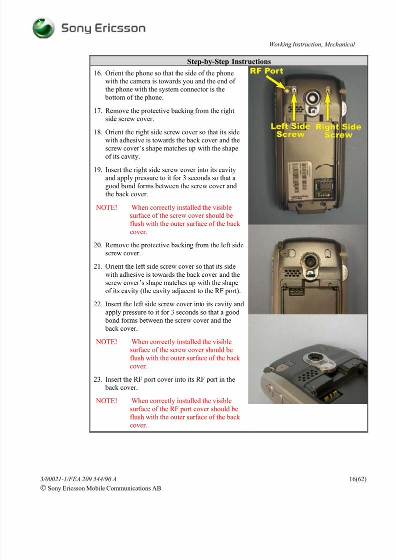
16. Orient the phone so that the side of the phone
with the camera is towards you and the end of
the phone with the system connector is the
bottom of the phone.
17. Remove the protective backing from the rightside screw cover.
18. Orient the right side screw cover so that its side
with adhesive is towards the back cover and the
screw cover’s shape matches up with the shape
of its cavity.
19. Insert the right side screw cover into its cavity
and apply pressure to it for 3 seconds so that a
good bond forms between the screw cover and
the back cover.
NOTE! When correctly installed the visiblesurface of the screw cover should be
flush with the outer surface of the back
cover.
20. Remove the protective backing from the left sidescrew cover.
21. Orient the left side screw cover so that its side
with adhesive is towards the back cover and the
screw cover’s shape matches up with the shape
of its cavity (the cavity adjacent to the RF port).22. Insert the left side screw cover into its cavity and
apply pressure to it for 3 seconds so that a good
bond forms between the screw cover and the
back cover.
NOTE! When correctly installed the visible
surface of the screw cover should be
flush with the outer surface of the back
cover.
23. Insert the RF port cover into its RF port in the
back cover.
NOTE! When correctly installed the visible
surface of the RF port cover should be
flush with the outer surface of the back
cover.
8/4/2019 P910 Working Instructions by Adalbertio
http://slidepdf.com/reader/full/p910-working-instructions-by-adalbertio 17/62
Working Instruction, Mechanical
3/00021-1/FEA 209 544/90 A
Sony Ericsson Mobile Communications AB
17(62)
Step-by-Step Instructions
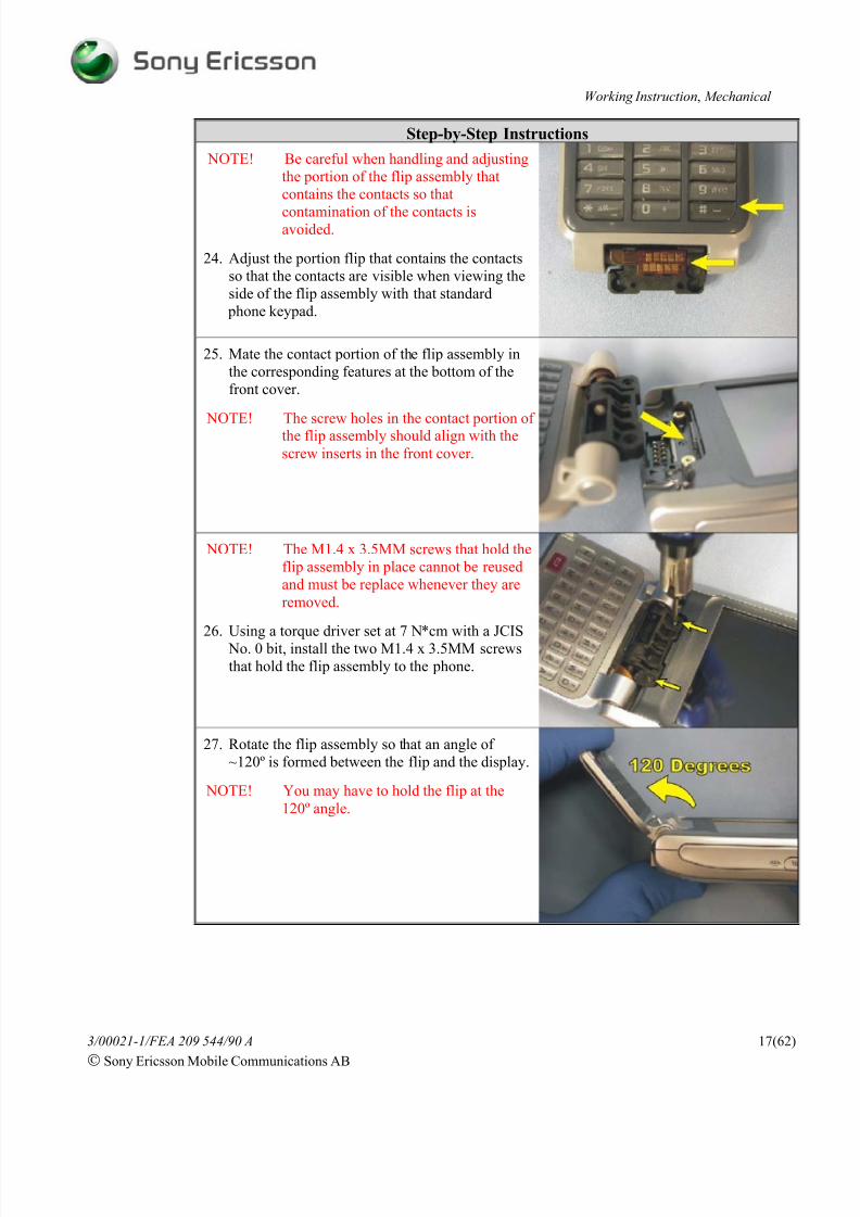
NOTE! Be careful when handling and adjusting
the portion of the flip assembly that
contains the contacts so that
contamination of the contacts isavoided.
24. Adjust the portion flip that contains the contacts
so that the contacts are visible when viewing the
side of the flip assembly with that standard
phone keypad.
25. Mate the contact portion of the flip assembly in
the corresponding features at the bottom of the
front cover.
NOTE! The screw holes in the contact portion of the flip assembly should align with the
screw inserts in the front cover.
NOTE! The M1.4 x 3.5MM screws that hold the
flip assembly in place cannot be reused
and must be replace whenever they are
removed.
26. Using a torque driver set at 7 N*cm with a JCIS
No. 0 bit, install the two M1.4 x 3.5MM screws
that hold the flip assembly to the phone.
27. Rotate the flip assembly so that an angle of
~120º is formed between the flip and the display.
NOTE! You may have to hold the flip at the
120º angle.
8/4/2019 P910 Working Instructions by Adalbertio
http://slidepdf.com/reader/full/p910-working-instructions-by-adalbertio 18/62
Working Instruction, Mechanical
3/00021-1/FEA 209 544/90 A
Sony Ericsson Mobile Communications AB
18(62)
Step-by-Step Instructions
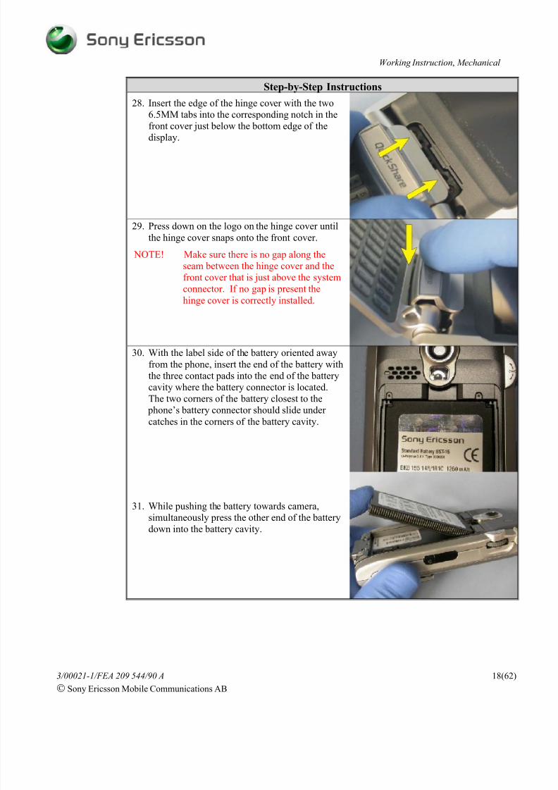
28. Insert the edge of the hinge cover with the two
6.5MM tabs into the corresponding notch in the
front cover just below the bottom edge of the
display.
29. Press down on the logo on the hinge cover until
the hinge cover snaps onto the front cover.
NOTE! Make sure there is no gap along the
seam between the hinge cover and the
front cover that is just above the systemconnector. If no gap is present the
hinge cover is correctly installed.
30. With the label side of the battery oriented away
from the phone, insert the end of the battery with
the three contact pads into the end of the battery
cavity where the battery connector is located.
The two corners of the battery closest to the
phone’s battery connector should slide under catches in the corners of the battery cavity.
31. While pushing the battery towards camera,
simultaneously press the other end of the battery
down into the battery cavity.

8/4/2019 P910 Working Instructions by Adalbertio
http://slidepdf.com/reader/full/p910-working-instructions-by-adalbertio 19/62
Working Instruction, Mechanical
3/00021-1/FEA 209 544/90 A
Sony Ericsson Mobile Communications AB
19(62)
Step-by-Step Instructions
32. Place the battery cover over the battery cavity, so
there is a 4 to 5 MM gap between the bottom of
camera window and top of the battery cover.
33. Press down on grip location on the battery cover
and simultaneously slide battery cover towards
the top of the phone (towards the camera
window).
4 Replacement of Mechanical Parts
4.1 Front Cover
Tools:
• 2A (blunt tip) ESD-safe tweezers • Lint-free wipes
• Perform the steps 1 - 22 of “Disassembly” section before proceeding
Step-by-Step Instructions1. Using 2A (blunt tip) tweezers, slide the tip of one
of the tweezers’ arms under the lip of the
accessible leg of the speaker holder.
2. Place a finger over the speaker holder to keep it
from flying off when releasing it.
3. Twist the tweezers away from the speaker and the
holder should release from its catch on the front
cover.

8/4/2019 P910 Working Instructions by Adalbertio
http://slidepdf.com/reader/full/p910-working-instructions-by-adalbertio 20/62
Working Instruction, Mechanical
3/00021-1/FEA 209 544/90 A
Sony Ericsson Mobile Communications AB
20(62)
Step-by-Step Instructions
4. Lift the holder from atop the speaker and set it
aside.
5. Lift the speaker from front cover.
6. Obtain a new front cover.
7. Place the speaker into the new front cover’s
speaker area. When placing the speaker, orient it
so that the speaker’s contacts are within the gap in
the side of the speaker area that is opposite to the
location where the tab portion of the speaker cloth
extends for the speaker area.
8. Locate the two catch features that are in the
placement walls around the speaker area.
9. Hook one of the legs of the speaker holder into
one of the placement wall catches.
10. Rotate the speaker holder down over the speaker
and press down on the speaker holder until the
unlatched leg of the speaker holder snaps into it
corresponding catch feature.
• Perform the steps of “Reassembly” section starting at the note before step 13 to complete the
reassembly of this phone.

8/4/2019 P910 Working Instructions by Adalbertio
http://slidepdf.com/reader/full/p910-working-instructions-by-adalbertio 21/62
Working Instruction, Mechanical
3/00021-1/FEA 209 544/90 A
Sony Ericsson Mobile Communications AB
21(62)
4.2 Front Speaker, Speaker Holder, and Speaker Cloth
Tools:
• 2A (blunt tip) ESD-safe tweezers • Lint-free wipes
• Perform the steps 1 - 22 of “Disassembly” section before proceeding.
Step-by-Step Instructions
1. Using 2A (blunt tip) tweezers, slide the tip of one
of the tweezers’ arms under the lip of the
accessible leg of the speaker holder.
2. Place a finger over the speaker holder to keep it
from flying off when releasing it.
3. Twist the tweezers away from the speaker and the
holder should release from its catch on the front
cover.
4. Lift the holder from atop the speaker and set itaside.
NOTE! If the speaker holder is the only
component being replaced, skip to step 8
and use a new speaker holder when
proceeding.
5. Lift the speaker from front cover.

8/4/2019 P910 Working Instructions by Adalbertio
http://slidepdf.com/reader/full/p910-working-instructions-by-adalbertio 22/62
Working Instruction, Mechanical
3/00021-1/FEA 209 544/90 A
Sony Ericsson Mobile Communications AB
22(62)
Step-by-Step Instructions
NOTE! The speaker cloth only has to be removed
if it is being replaced, otherwise skip the
following step.
6. If replacing the speaker cloth:
a. Slide the tip of a tweezers’ arm under the tab
portion of the speaker cloth and peel the
speaker cloth up from the front cover.
b. Remove any remaining adhesive residue from
the speaker cloth attachment area.
c. Place a new speaker cloth in the front cover as
shown. The side of the speaker cloth with
adhesive mates to the front cover. The tab
portion of the speaker cloth should cover the
rectangular opening that is adjacent to the
speaker area and the round portion of the
speaker cloth should completely fill the
bottom of the speaker area.
NOTE! If the speaker is the component beingreplaced, a new speaker should be used
when performing the following steps.
7. Place a speaker into the front cover’s speaker area.
When placing the speaker, orient it so that the
speaker’s contacts are within the gap in the side of
the speaker area that is opposite to the location
where the tab portion of the speaker cloth extends
for the speaker area.
8. Locate the two catch features that are in the
placement walls around the speaker area.
9. Hook one of the legs of the speaker holder into one
of the catch features in the placement wall.
10. Rotate the speaker holder down over the speaker
and press down on the speaker holder until the
unlatched leg of the speaker holder snaps into it
corresponding catch feature.
• Perform the steps of “Reassembly” section starting at the note before step 13 to complete the
reassembly of this phone.
NOTE! If the front speaker is replaced, the front speaker audio reset software must be run on
the phone. Instructions for running the speaker audio reset can be found in the Test
Instruction, Mechanical.

8/4/2019 P910 Working Instructions by Adalbertio
http://slidepdf.com/reader/full/p910-working-instructions-by-adalbertio 23/62
Working Instruction, Mechanical
3/00021-1/FEA 209 544/90 A
Sony Ericsson Mobile Communications AB
23(62)
4.3 RF Port Cover
Tools: • Nylon Pointer
Step-by-Step Instructions
1. Orient the phone so that the side of the phonewith the camera is towards you and the end of
the phone with the system connector is the
bottom of the phone.
2. Insert the pointed end of the nylon pointer into
small hole in the RF port cover and rotate the
nylon pointer down towards the outer edge of the
phone. The RF port cover should lift from it
cavity.
3. Insert a RF port cover into the RF port in the
back cover.
NOTE! When correctly installed the visible
surface of the RF port cover should be
flush with the outer surface of the back
cover.
4.4 Battery Cover
The removal and installation of this part is covered in the “Disassembly” and “Reassembly”
sections of this document. Limit the amount of disassembly to only that which is needed to
remove this part. If this part is being replaced, a new part should be used in the place of the old
part when reassembling.
4.5 Display
The removal and installation of this part is covered in the “Disassembly” and “Reassembly”
sections of this document. Limit the amount of disassembly to only that which is needed to
remove this part. If this part is being replaced, a new part should be used in the place of the old
part when reassembling. Two cushions and a spacer must be mounted on a new display before it
can be used. The installation of these two cushions and the spacer are covered in the
“Reassembly” section.
8/4/2019 P910 Working Instructions by Adalbertio
http://slidepdf.com/reader/full/p910-working-instructions-by-adalbertio 24/62
Working Instruction, Mechanical
3/00021-1/FEA 209 544/90 A
Sony Ericsson Mobile Communications AB
24(62)
4.6 Flip Assembly
The removal and installation of this part is covered in the “Disassembly” and “Reassembly”
sections of this document. Limit the amount of disassembly to only that which is needed to
remove this part. If this part is being replaced, a new part should be used in the place of the old part when reassembling.
4.7 Flip Hinge Cover
The removal and installation of this part is covered in the “Disassembly” and “Reassembly”
sections of this document. Limit the amount of disassembly to only that which is needed to
remove this part. If this part is being replaced, a new part should be used in the place of the old
part when reassembling.
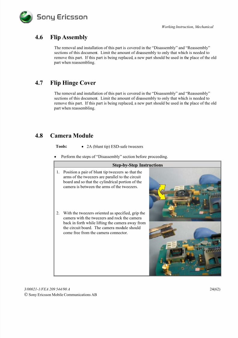
4.8 Camera Module
Tools: • 2A (blunt tip) ESD-safe tweezers
• Perform the steps of “Disassembly” section before proceeding.
Step-by-Step Instructions
1. Position a pair of blunt tip tweezers so that the
arms of the tweezers are parallel to the circuit board and so that the cylindrical portion of the
camera is between the arms of the tweezers.
2. With the tweezers oriented as specified, grip the
camera with the tweezers and rock the camera
back in forth while lifting the camera away from
the circuit board. The camera module should
come free from the camera connector.

8/4/2019 P910 Working Instructions by Adalbertio
http://slidepdf.com/reader/full/p910-working-instructions-by-adalbertio 25/62
Working Instruction, Mechanical
3/00021-1/FEA 209 544/90 A
Sony Ericsson Mobile Communications AB
25(62)
Step-by-Step Instructions
3. Orient a new camera module so that flat side of
the cylindrical portion of the camera module is
adjacent to the antenna connection.
4. Once correctly oriented, insert the new camera
module into the camera connector and press the
camera module down into the camera connector
until it is fully seated.
NOTE! Make sure that the top of the camera
module is parallel with the surface of
the board. If the camera module is not
parallel, check whether the camera
module is completely seated down into
the camera connector.
• Perform the steps of “Reassembly” section to complete the reassembly of this phone.

8/4/2019 P910 Working Instructions by Adalbertio
http://slidepdf.com/reader/full/p910-working-instructions-by-adalbertio 26/62
Working Instruction, Mechanical
3/00021-1/FEA 209 544/90 A
Sony Ericsson Mobile Communications AB
26(62)
4.9 Back Cover
Tools:
•Torque screwdriver
•Orange stick
• JCIS No. 0 bit • Nylon pointer
• Style 2A ESD-safe tweezers (Blunt Tip) • Front opening tool
NOTE! Whenever the phrase “pry tool” is used, a nylon pointer, an orange stick, or a front
opening tool may be used, depending on the user’s preference.
• Perform the steps of “Disassembly” section before proceeding.
Step-by-Step Instructions1. Remove the camera gasket from its position in
the back cover using a pair of tweezers.
NOTE! The camera gasket some times sticks to
the circuit board when the circuit boardis removed so if the speaker gasket is
not present in the back cover locate it.
2. Remove the stylus by sliding it away from the
back cover as indicated.
8/4/2019 P910 Working Instructions by Adalbertio
http://slidepdf.com/reader/full/p910-working-instructions-by-adalbertio 27/62
Working Instruction, Mechanical
3/00021-1/FEA 209 544/90 A
Sony Ericsson Mobile Communications AB
27(62)
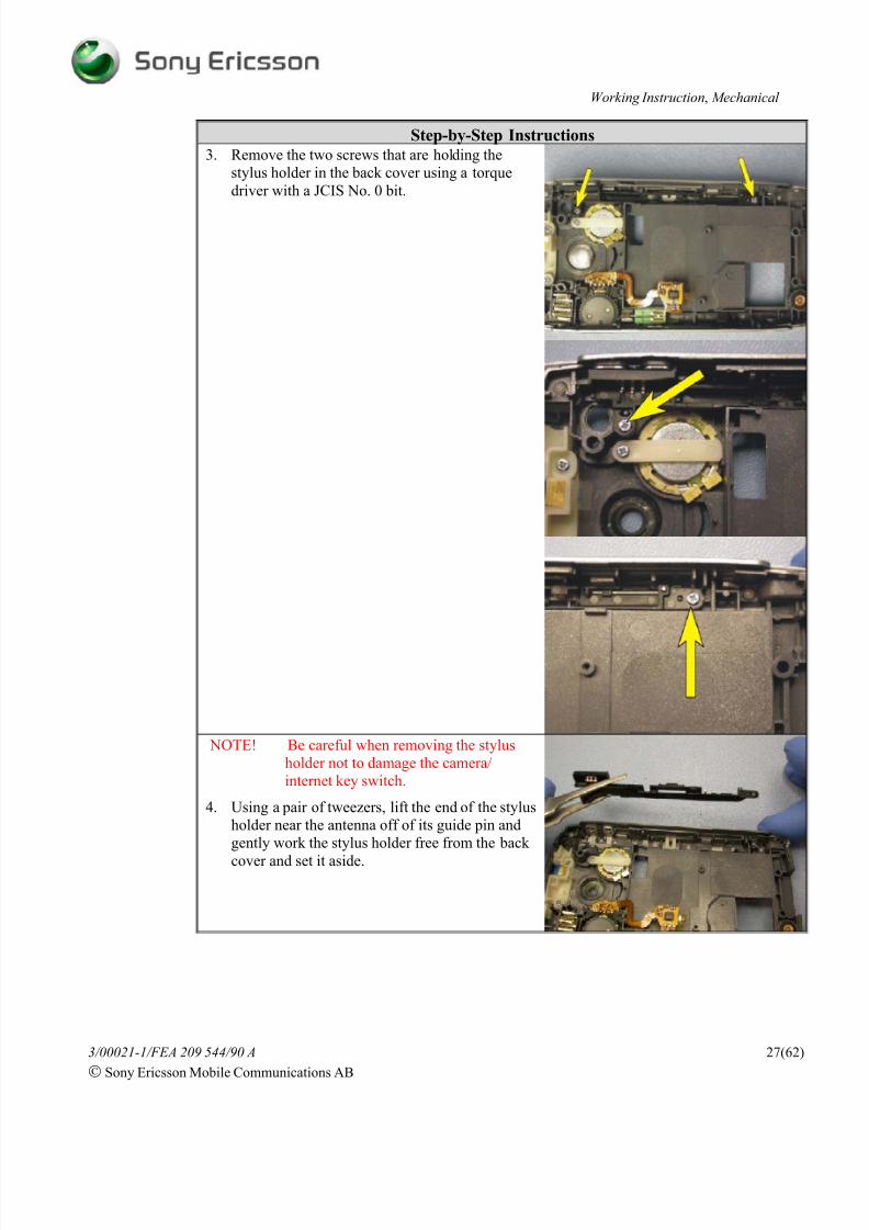
Step-by-Step Instructions3. Remove the two screws that are holding the
stylus holder in the back cover using a torque
driver with a JCIS No. 0 bit.
NOTE! Be careful when removing the stylus
holder not to damage the camera/
internet key switch.
4. Using a pair of tweezers, lift the end of the stylus
holder near the antenna off of its guide pin and
gently work the stylus holder free from the back
cover and set it aside.

8/4/2019 P910 Working Instructions by Adalbertio
http://slidepdf.com/reader/full/p910-working-instructions-by-adalbertio 28/62
Working Instruction, Mechanical
3/00021-1/FEA 209 544/90 A
Sony Ericsson Mobile Communications AB
28(62)
Step-by-Step Instructions5. Remove the memory stick cover from the access
hole in the side of the back cover. Once free
from its access hole, the memory stick cover
should lift out of the hole.
6. Using a torque driver with a JCIS No. 0 bit,
remove the screw that is holding the rear speaker
holder in the back cover.
7. Lift the speaker holder from atop the rear
speaker and set it aside.
8. Rotate the back cover so that the rear speaker
and its speaker cloth fall into your hand. Then
set the items aside.
NOTE! If the speaker cloth does not fall out of
the speaker cavity into your hand,
remove the speaker cloth from the back
cover using a pair of tweezers.

8/4/2019 P910 Working Instructions by Adalbertio
http://slidepdf.com/reader/full/p910-working-instructions-by-adalbertio 29/62
Working Instruction, Mechanical
3/00021-1/FEA 209 544/90 A
Sony Ericsson Mobile Communications AB
29(62)
Step-by-Step Instructions NOTE! Be careful not to damage the antenna
when removing the antenna assembly.
9. Remove the two M1.4 x 4MM screws that hold
the antenna using a torque driver with a JCIS No. 0 bit.
10. Using the tip of one arm of a pair of blunt tip
tweezers, pry between the back cover and the
antenna assembly at one of the antennaassembly’s board latches to free that side of the
antenna assembly from its catch feature in the
back cover.
11. Once one side of the antenna assembly is free,
repeat the same procedure at the antenna
assembly’s other board latch.
12. Continue prying at each of the antenna
assembly’s board latches until the edge of the
antenna assembly clears the bottom edge of the
back cover latches that hold the top of the front
cover in place.

8/4/2019 P910 Working Instructions by Adalbertio
http://slidepdf.com/reader/full/p910-working-instructions-by-adalbertio 30/62
Working Instruction, Mechanical
3/00021-1/FEA 209 544/90 A
Sony Ericsson Mobile Communications AB
30(62)
Step-by-Step Instructions13. Once all of the features of the back cover that the
antenna could get hung on have been cleared, lift
the antenna assembly from the back cover.
NOTE! Do not press on the antenna’s contact
pad when reinstalling the antenna
assembly, contamination of the pad may
occur.
14. Obtain a new back cover and position theantenna assembly in the back cover in the
location shown.
15. Then press the antenna assembly down into the
back cover until each end of the antenna
assembly catches under the latches in the back
cover that hold the antenna in place.
16. Using a torque driver set at 7 N*cm with a JCIS
No. 0 bit, install the two M1.4 x 4MM screws
that hold the antenna.
17. Locate where a portion of the jog dial’s flex film
is pressed down around an alignment peg
protruding from the back cover. Using a pair of
blunt tip tweezers, free the flex film from the
alignment peg.

8/4/2019 P910 Working Instructions by Adalbertio
http://slidepdf.com/reader/full/p910-working-instructions-by-adalbertio 31/62
Working Instruction, Mechanical
3/00021-1/FEA 209 544/90 A
Sony Ericsson Mobile Communications AB
31(62)
Step-by-Step Instructions18. Locate the “gull wing” portion of the jog dial
that mates with features in the back cover to hold
the jog dial in place.
19. Insert the tip of a pair of blunt tip tweezers in thegap between the back cover and the portion of
the “gull wing” that is perpendicular to the jog
dial’s flex film.
20. Pry inward (towards the jog dial) and upward
(away from the back cover) simultaneously until
the latch feature of the jog dial becomes
unhooked from the back cover.
21. Once one of the latch features is free from the
back cover, lift the latch feature that is free away
from the back cover while pressing inward on
the dial itself until the jog dial assembly liftsfrom the back cover.

8/4/2019 P910 Working Instructions by Adalbertio
http://slidepdf.com/reader/full/p910-working-instructions-by-adalbertio 32/62
Working Instruction, Mechanical
3/00021-1/FEA 209 544/90 A
Sony Ericsson Mobile Communications AB
32(62)
Step-by-Step Instructions
22. Insert the jog dial into the new back cover so that
the dial portion protrudes through the slot in the
side of the back cover and the two wings of the
gull wing portion of the jog dial are aligned withthe their corresponding back cover notches.
23. Press one of the jog dial’s wings into its
corresponding notch in the back cover until the
wing snaps into place.
24. Press the other wing into its corresponding notchin the back cover until the wing snaps into place.
The jog dial is now installed.
25. Using a pair of tweezers, work the vibrator from
its cavity by gently lifting the vibrator by its
weight.
NOTE! Be careful not to damage the vibrator
contacts or to bend the shaft of thevibrator when removing it.
26. When installing the vibrator into the new back
cover, orient the vibrator so that its weight is
toward the jog dial, the contacts are facing out
away from the back cover, and the placement
features along each side of the vibrator’s boot
are aligned with the corresponding notches in
side walls of the vibrator cavity.
27. Place the vibrator over the vibrator cavity and
gently press it into place.
NOTE! Do not push on the vibrator contacts!

8/4/2019 P910 Working Instructions by Adalbertio
http://slidepdf.com/reader/full/p910-working-instructions-by-adalbertio 33/62
Working Instruction, Mechanical
3/00021-1/FEA 209 544/90 A
Sony Ericsson Mobile Communications AB
33(62)
Step-by-Step Instructions
NOTE! Avoid damaging or contaminating the
conductive elastomer when removing or
reinstalling the microphone assembly.
If the conductive elastomer comes off during the removal of the microphone
assembly, use a new microphone
assembly in the new back cover.
28. Remove the microphone assembly from the
microphone cavity in the back cover.
29. Insert the microphone assembly into the
microphone cavity of the new back cover so that
the side of the microphone assembly with the
three holes is down inside the microphone
cavity. Use the flat end of a pry tool to press themicrophone assembly down into it cavity so that
contamination of the conductive elastomer is
avoided.
NOTE! The side of the microphone assembly
with the two gold concentric rings is
the side of the microphone assembly
that should be visible if the
microphone assembly is correctly
installed. There should be a clear
elastomer over the top of the two gold
concentric rings.
30. Remove the audio jack cover from the audio jack
hole.

8/4/2019 P910 Working Instructions by Adalbertio
http://slidepdf.com/reader/full/p910-working-instructions-by-adalbertio 34/62
Working Instruction, Mechanical
3/00021-1/FEA 209 544/90 A
Sony Ericsson Mobile Communications AB
34(62)
Step-by-Step Instructions
31. Insert the tip of a pair of blunt tip tweezers into
the audio jack hole. Gently rotate the tweezers
down towards the audio jack cover and the audio
jack should lift free from its cavity.
32. Locate the portion of the audio jack cover that is
pressed down around an alignment peg. Using a
pair of blunt tip tweezers, free the audio jack
cover from the alignment peg.
33. Gripping the external portion of the audio jack
cover, pull it perpendicular to the battery cavity
and it should easily side out of the back cover.
34. Orient the audio jack cover so that the side of thecover with the plug will mate with the hole in the
audio jack once installed.
35. Slide the leg of the audio jack cover through the
hole in the new back cover indicated.

8/4/2019 P910 Working Instructions by Adalbertio
http://slidepdf.com/reader/full/p910-working-instructions-by-adalbertio 35/62
Working Instruction, Mechanical
3/00021-1/FEA 209 544/90 A
Sony Ericsson Mobile Communications AB
35(62)
Step-by-Step Instructions
36. Wrap the audio jack cover into its cavity on the
outside of the back cover and hold it there while
pressing the leg of the audio jack cover down
over the alignment peg at the bottom of the audio jack cavity.
37. Orient the audio jack so that its end with the hole
is oriented towards the wall of the audio jack
cavity with the corresponding hole.
38. Insert the end of the audio jack with the hole first
so that the cyclindrical portion extending from
the side of the jack can slide inside the hole in
the wall.
39. Then press the other end of the audio jack down
into the audio jack cavity.
40. Insert the speaker cloth into the speaker cavity of
the new back cover so that the side of the
speaker cloth with the gasket is oriented away
from the back cover as shown.

8/4/2019 P910 Working Instructions by Adalbertio
http://slidepdf.com/reader/full/p910-working-instructions-by-adalbertio 36/62
Working Instruction, Mechanical
3/00021-1/FEA 209 544/90 A
Sony Ericsson Mobile Communications AB
36(62)
Step-by-Step Instructions
41. Place the speaker in the speaker cavity and
position it by placing the alignment feature on
the edge of the speaker into the notch in the wall
of the speaker cavity as shown.
42. Place the speaker holder over the speaker so its
notched end is inside the pocket above where the
speaker cavity wall and battery cavity wall
connect. Position the other end (rounded end) of
the speaker holder so that it is seated over thescrew boss above the speaker.
43. With both ends of the speaker holder in place
insert a M1.4 x 4MM screw through the hole in
the rounded end of the speaker holder and torque
the screw into place using a torque driver set at
7 N*cm and a JCIS No. 0 bit.
44. Insert the memory stick cover into its socket in
the side of the new back cover as shown.
45. Orient the stylus holder so that the screw hole
near each end matches up with their
corresponding screw bosses in the back cover.
46. Work the stylus holder down into its cavity in
the back cover.
NOTE! Be careful not to damage the camera/
internet switch when installing the
stylus holder.

8/4/2019 P910 Working Instructions by Adalbertio
http://slidepdf.com/reader/full/p910-working-instructions-by-adalbertio 37/62
Working Instruction, Mechanical
3/00021-1/FEA 209 544/90 A
Sony Ericsson Mobile Communications AB
37(62)
Step-by-Step Instructions
47. Verify that the hole in each screw boss is visible
through the corresponding hole in each end of
the stylus holder. Also verify that the alignment
peg adjacent to each screw boss protrudesthrough their corresponding holes in the stylus
holder.
48. With the stylus holder in place, install a M1.4 x
4MM screw in both screw holes and torque the
screws into place using a torque driver set at
7N*cm and a JCIS No. 0 bit.

8/4/2019 P910 Working Instructions by Adalbertio
http://slidepdf.com/reader/full/p910-working-instructions-by-adalbertio 38/62
Working Instruction, Mechanical
3/00021-1/FEA 209 544/90 A
Sony Ericsson Mobile Communications AB
38(62)
Step-by-Step Instructions
49. Obtain a new camera window assembly and
remove the protective film from its adhesive
surface.
50. Locate the cavity on the outer surface of the new
back cover that corresponds to the shape of the
camera window assembly.
51. Mount the new camera window assembly into its
corresponding cavity on the new back cover and
apply pressure for 3 seconds to assure a good
bond forms.
52. Install the stylus by sliding it into the hole in the
outer surface of the back cover as indicated.

8/4/2019 P910 Working Instructions by Adalbertio
http://slidepdf.com/reader/full/p910-working-instructions-by-adalbertio 39/62
Working Instruction, Mechanical
3/00021-1/FEA 209 544/90 A
Sony Ericsson Mobile Communications AB
39(62)
Step-by-Step Instructions
NOTE! When installing the camera gasket, a
portion of the camera gasket has to be
worked under a speaker contact
53. Insert the camera gasket into to the back cover as
shown.
NOTE! Make sure that an alignment peg
protrudes through the hole at each end
of the camera gasket.
• Perform the steps of the “Reassembly” section to complete the reassembly of this phone.
• A new label must be generated and installed. Refer to the “Label” section for steps on
creating and installing a label.
4.10 Internet Key
This part is heat stacked to back cover, therefore to replace this part you must replace the back
cover of the phone. Refer to the “Back Cover” section of this document for instructions on
replacing the back cover.
4.11 Camera Key
This part is heat stacked to back cover, therefore to replace this part you must replace the back
cover of the phone. Refer to the “Back Cover” section of this document for instructions onreplacing the back cover.
4.12 Power On/Off Key
This part is heat stacked to back cover, therefore to replace this part you must replace the back
cover of the phone. Refer to the “Back Cover” section of this document for instructions on
replacing the back cover.

8/4/2019 P910 Working Instructions by Adalbertio
http://slidepdf.com/reader/full/p910-working-instructions-by-adalbertio 40/62
Working Instruction, Mechanical
3/00021-1/FEA 209 544/90 A
Sony Ericsson Mobile Communications AB
40(62)
4.13 Camera Gasket
Tools: • 2A (blunt tip) ESD-safe tweezers
• Perform the steps of “Disassembly” section before proceeding.
Step-by-Step Instructions1. Remove the camera gasket from its position in
the back cover using a pair of tweezers.
NOTE! The camera gasket some times sticks to
the circuit board when the circuit board
is removed so if the speaker gasket is
not present in the back cover locate it.
NOTE! When installing the camera gasket, a
portion of the camera gasket has to be
worked under a speaker contact
2. Insert the camera gasket into to the back cover as
shown.
NOTE! Make sure that an alignment peg
protrudes through the hole at each end
of the camera gasket.
• Perform the steps of the “Reassembly” section to complete the reassembly of this phone.

8/4/2019 P910 Working Instructions by Adalbertio
http://slidepdf.com/reader/full/p910-working-instructions-by-adalbertio 41/62
Working Instruction, Mechanical
3/00021-1/FEA 209 544/90 A
Sony Ericsson Mobile Communications AB
41(62)
4.14 Vibrator
The removal and installation of this part is covered in the “Back Cover” section of this document.
Assume that this part is being replaced instead of the back cover. A new part should be used in
the place of the old part when reassembling. Limit the amount of disassembly to only that whichis needed to replace this part.
4.15 Rear Speaker, Holder, and Cloth
The removal and installation of these parts is covered in the “Back Cover” section of this
document. Replace the needed part instead of the back cover when performing instructions of
the back cover section. A new part should be used in the place of the old part when reassembling.
Limit the amount of disassembly to only that which is needed to remove the part that is being
replaced.
4.16 Audio Jack and Audio Jack Cover
The removal and installation of these parts is covered in the “Back Cover” section of this
document. Replace the needed part instead of the back cover when performing instructions of
the back cover section. A new part should be used in the place of the old part when reassembling.
Limit the amount of disassembly to only that which is needed to remove the part that is being
replaced.
4.17 Microphone Assembly and Microphone ClothTools:
• Style 2A ESD-safe tweezers (Blunt Tip) • Nylon pointer
• Front opening tool • Orange stick
NOTE! Whenever the phrase “pry tool” is used, a nylon pointer, an orange stick, or a front
opening tool may be used, depending on the user’s preference.
• Perform the steps of “Disassembly” section before proceeding.
Step-by-Step Instructions
NOTE! Avoid damaging or contaminating the
conductive elastomer when removing or installing the microphone assembly.
NOTE! If the conductive elastomer comes off
during the removal of the microphone
assembly, use a new microphone
assembly.
1. Remove the microphone assembly from the
microphone cavity in the back cover.
8/4/2019 P910 Working Instructions by Adalbertio
http://slidepdf.com/reader/full/p910-working-instructions-by-adalbertio 42/62
Working Instruction, Mechanical
3/00021-1/FEA 209 544/90 A
Sony Ericsson Mobile Communications AB
42(62)
Step-by-Step Instructions
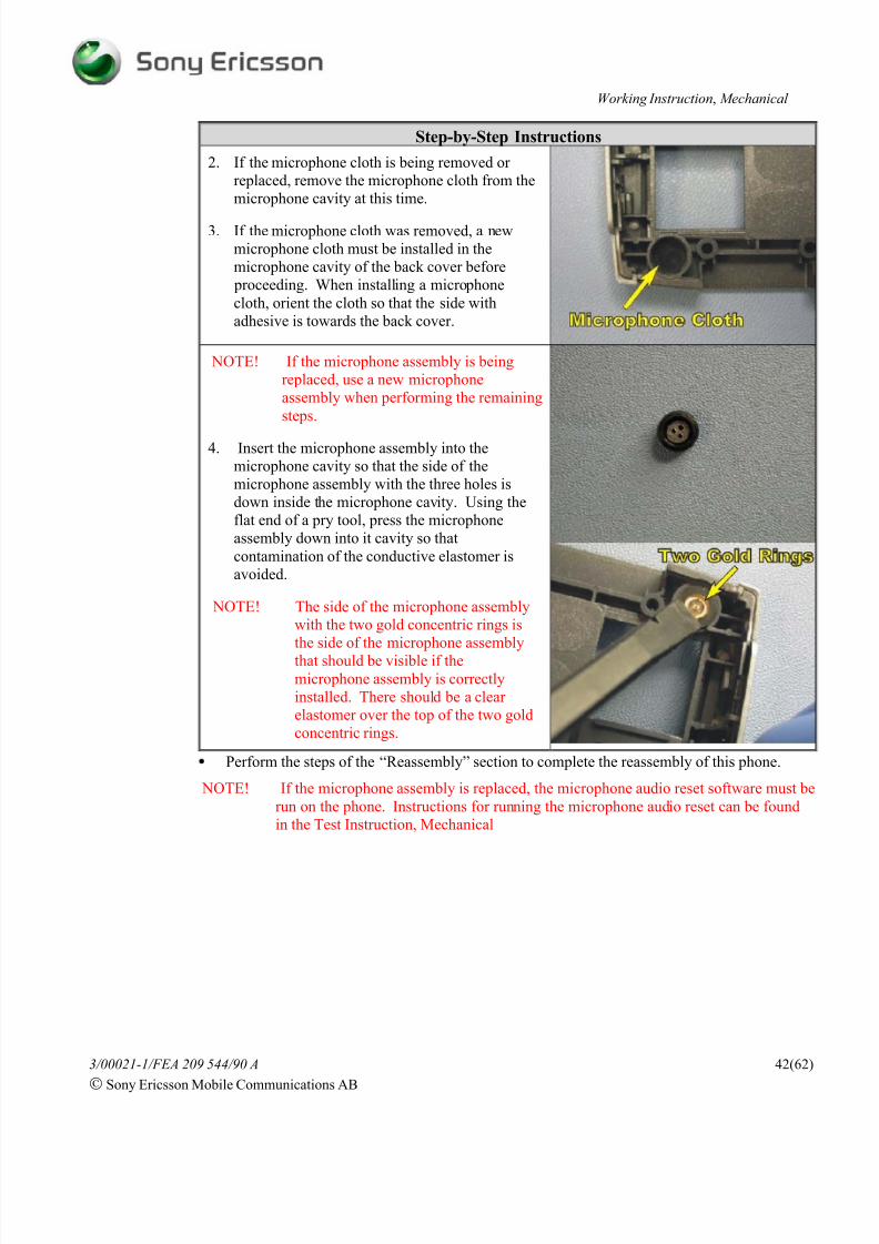
2. If the microphone cloth is being removed or
replaced, remove the microphone cloth from the
microphone cavity at this time.
3. If the microphone cloth was removed, a new
microphone cloth must be installed in the
microphone cavity of the back cover before
proceeding. When installing a microphone
cloth, orient the cloth so that the side with
adhesive is towards the back cover.
NOTE! If the microphone assembly is being
replaced, use a new microphone
assembly when performing the remaining
steps.
4. Insert the microphone assembly into the
microphone cavity so that the side of the
microphone assembly with the three holes is
down inside the microphone cavity. Using the
flat end of a pry tool, press the microphone
assembly down into it cavity so that
contamination of the conductive elastomer is
avoided.
NOTE! The side of the microphone assembly
with the two gold concentric rings is
the side of the microphone assembly
that should be visible if the
microphone assembly is correctly
installed. There should be a clear
elastomer over the top of the two gold
concentric rings.
• Perform the steps of the “Reassembly” section to complete the reassembly of this phone.
NOTE! If the microphone assembly is replaced, the microphone audio reset software must be
run on the phone. Instructions for running the microphone audio reset can be found
in the Test Instruction, Mechanical

8/4/2019 P910 Working Instructions by Adalbertio
http://slidepdf.com/reader/full/p910-working-instructions-by-adalbertio 43/62
Working Instruction, Mechanical
3/00021-1/FEA 209 544/90 A
Sony Ericsson Mobile Communications AB
43(62)
4.18 Jog Dial
Tools: • 2A (blunt tip) ESD-safe tweezers
• Perform the steps of “Disassembly” section before proceeding.
Step-by-Step Instructions1. Remove the camera gasket from its position in
the back cover using a pair of tweezers.
NOTE! The camera gasket some times sticks to
the circuit board when the circuit board
is removed so if the speaker gasket is
not present in the back cover locate it.
2. Locate where a portion of the jog dial’s flex film
is pressed down around an alignment peg
protruding from the back cover. Using a pair of
blunt tip tweezers, free the flex film from the
alignment peg.

8/4/2019 P910 Working Instructions by Adalbertio
http://slidepdf.com/reader/full/p910-working-instructions-by-adalbertio 44/62
Working Instruction, Mechanical
3/00021-1/FEA 209 544/90 A
Sony Ericsson Mobile Communications AB
44(62)
Step-by-Step Instructions3. Locate the “gull wing” portion of the jog dial
that holds the jog dial in place by mating with
features in the back cover.
4. Insert the tip of a pair of blunt tip tweezers in the
gap between the back cover and the portion of
the “gull wing” that is perpendicular to the jog
dial’s flex film.
5. Pry inward (towards the jog dial) and upward
(away from the back cover) simultaneously until
the latch feature of the jog dial becomes
unhooked from the back cover.
6. Once one of the latch features is free from the
back cover, lift that latch feature away from the
back cover while pressing inward on the dial
itself until the jog dial assembly lifts from the back cover.

8/4/2019 P910 Working Instructions by Adalbertio
http://slidepdf.com/reader/full/p910-working-instructions-by-adalbertio 45/62
Working Instruction, Mechanical
3/00021-1/FEA 209 544/90 A
Sony Ericsson Mobile Communications AB
45(62)
Step-by-Step Instructions
7. Insert a new jog dial into the back cover so that
the dial portion protrudes through the slot in the
side of the back cover and the two wings of the
gull wing portion of the jog dial are aligned withthe their corresponding notches in the back
cover.
8. Press one the jog dial’s wings into itscorresponding notch until the wing snaps into
place.
9. Press the other wing into its corresponding notch
until the wing snaps into place. The jog dial isnow installed.
NOTE! When installing the camera gasket, a
portion of the camera gasket has to be
worked under a speaker contact
10. Insert the camera gasket into to the back cover as
shown.
NOTE! Make sure that an alignment peg
protrudes through the hole at each end
of the camera gasket.
• Perform the steps of the “Reassembly” section to complete the reassembly of this phone.
8/4/2019 P910 Working Instructions by Adalbertio
http://slidepdf.com/reader/full/p910-working-instructions-by-adalbertio 46/62
Working Instruction, Mechanical
3/00021-1/FEA 209 544/90 A
Sony Ericsson Mobile Communications AB
46(62)
4.19 Antenna Assembly
Tools: • Style 2A ESD-safe tweezers (Blunt Tip)
• Torque screwdriver • JCIS No. 0 bit
• Nylon pointer • Orange stick • Front opening tool
NOTE! Whenever the phrase “pry tool” is used, a nylon pointer, an orange stick, or a front
opening tool may be used, depending on the user’s preference.
• Perform the steps of “Disassembly” section before proceeding.
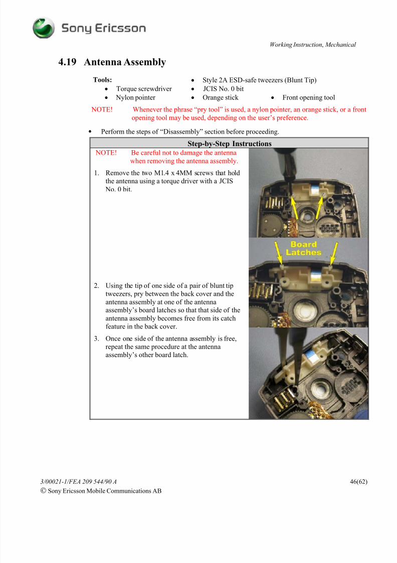
Step-by-Step Instructions NOTE! Be careful not to damage the antenna
when removing the antenna assembly.
1. Remove the two M1.4 x 4MM screws that hold
the antenna using a torque driver with a JCIS
No. 0 bit.
2. Using the tip of one side of a pair of blunt tip
tweezers, pry between the back cover and theantenna assembly at one of the antennaassembly’s board latches so that that side of the
antenna assembly becomes free from its catch
feature in the back cover.
3. Once one side of the antenna assembly is free,
repeat the same procedure at the antenna
assembly’s other board latch.

8/4/2019 P910 Working Instructions by Adalbertio
http://slidepdf.com/reader/full/p910-working-instructions-by-adalbertio 47/62
Working Instruction, Mechanical
3/00021-1/FEA 209 544/90 A
Sony Ericsson Mobile Communications AB
47(62)
Step-by-Step Instructions4. Continue prying at each of the antenna
assembly’s board latches until the edge of the
antenna assembly clears the bottom edge of the
back cover latches that hold the top of the frontcover in place.
5. Once all of the features of the back cover that the
antenna could get hung on have been cleared, lift
the antenna assembly from the back cover.
NOTE! If the antenna or the antenna support is
being replaced, use new parts for both
items when putting together the antenna
assembly.
NOTE! Handle the new antenna by it two non-
adhesive tabs.
6. Remove a new antenna from its protective
backing.
7. Orient the new antenna and the new antenna
support so that the adhesive side of the antenna
is towards of the curved outer surface of the
antenna support.

8/4/2019 P910 Working Instructions by Adalbertio
http://slidepdf.com/reader/full/p910-working-instructions-by-adalbertio 48/62
Working Instruction, Mechanical
3/00021-1/FEA 209 544/90 A
Sony Ericsson Mobile Communications AB
48(62)
Step-by-Step Instructions8. Align the edge of the antenna from which the
contact pad extends to the curved outline that
runs tangent to the edge of the antenna support
that has a notch for the extension of the antennato fold down into as shown.

8/4/2019 P910 Working Instructions by Adalbertio
http://slidepdf.com/reader/full/p910-working-instructions-by-adalbertio 49/62
Working Instruction, Mechanical
3/00021-1/FEA 209 544/90 A
Sony Ericsson Mobile Communications AB
49(62)
Step-by-Step Instructions9. Rotate the extension of the antenna with the
contact pad down onto the ledge that is behind it.
NOTE! When the extension of the antenna is
correctly positioned on the ledge theedge of the antenna contact pad should
be aligned with the end of the ledge.
10. Once the extension of the antenna is in position,
use the flat end of a pry tool to apply pressure so
that a good bond forms between the two parts
while avoiding contamination of the antenna’s
contact pad.
11. Make sure that the edge of the antenna from
which the contact pad extends is still aligned
with the curved outline that runs tangent to the
edge of the antenna support with the notch that
the extension of the antenna folds down into.
12. Once positioned smooth the remaining portion of
the antenna on to the antenna support.
NOTE! Do not press on the antenna’s contact
pad when reinstalling the antenna,
contamination of the pad may occur.
13. Position the antenna assembly in the back cover
in the location shown.
14. Then press the antenna assembly down into the back cover until each end of the antenna
assembly catches under the latches in the back
cover that hold the antenna in place.
8/4/2019 P910 Working Instructions by Adalbertio
http://slidepdf.com/reader/full/p910-working-instructions-by-adalbertio 50/62
Working Instruction, Mechanical
3/00021-1/FEA 209 544/90 A
Sony Ericsson Mobile Communications AB
50(62)
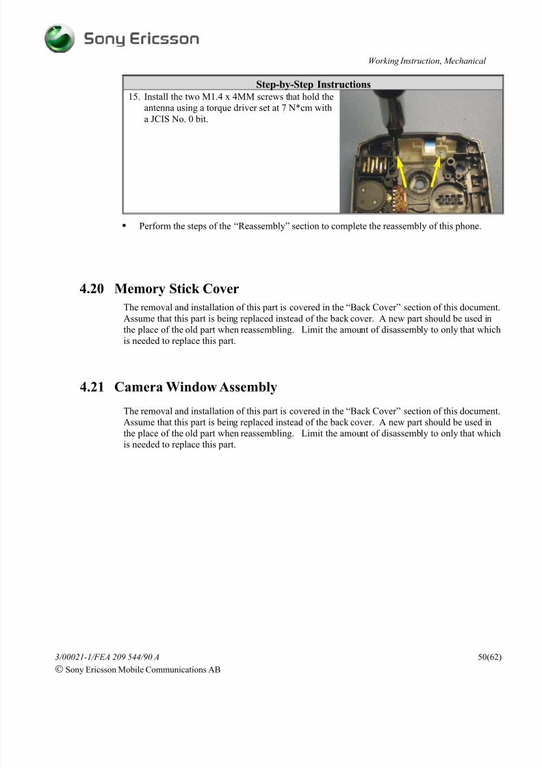
Step-by-Step Instructions15. Install the two M1.4 x 4MM screws that hold the
antenna using a torque driver set at 7 N*cm with
a JCIS No. 0 bit.
• Perform the steps of the “Reassembly” section to complete the reassembly of this phone.
4.20 Memory Stick Cover
The removal and installation of this part is covered in the “Back Cover” section of this document.
Assume that this part is being replaced instead of the back cover. A new part should be used in
the place of the old part when reassembling. Limit the amount of disassembly to only that which
is needed to replace this part.
4.21 Camera Window Assembly
The removal and installation of this part is covered in the “Back Cover” section of this document.
Assume that this part is being replaced instead of the back cover. A new part should be used in
the place of the old part when reassembling. Limit the amount of disassembly to only that which
is needed to replace this part.

8/4/2019 P910 Working Instructions by Adalbertio
http://slidepdf.com/reader/full/p910-working-instructions-by-adalbertio 51/62
Working Instruction, Mechanical
3/00021-1/FEA 209 544/90 A
Sony Ericsson Mobile Communications AB
51(62)
4.22 Camera/Internet Key Switch
Tools: • Style 2A ESD-safe tweezers (Blunt Tip)
• Torque screwdriver • JCIS No. 0 bit• Perform the steps of “Disassembly” section before proceeding.
Step-by-Step Instructions1. Remove the two screws that are holding the
stylus holder in the back cover using a torque
driver with a JCIS No. 0 bit.

8/4/2019 P910 Working Instructions by Adalbertio
http://slidepdf.com/reader/full/p910-working-instructions-by-adalbertio 52/62
Working Instruction, Mechanical
3/00021-1/FEA 209 544/90 A
Sony Ericsson Mobile Communications AB
52(62)
Step-by-Step Instructions2. Using a pair of tweezers, lift the end of the stylus
holder near the antenna off of its guide pin and
gently work the stylus holder free from the back
cover and set it aside.
NOTE! Be careful not to damage the stylus
holder when removing the
camera/internet key switch.
3. Using a pair of blunt tip tweezers, pry the
camera/internet key switch from the stylusholder.
4. If any of the adhesive tape that holds the
camera/internet key switch in place remains on
the stylus holder remove it and clean the cavity
with alcohol and a lint-free wipe.
5. Place a new piece of adhesive tape in the
camera/internet key switch’s cavity oriented as
shown.

8/4/2019 P910 Working Instructions by Adalbertio
http://slidepdf.com/reader/full/p910-working-instructions-by-adalbertio 53/62
Working Instruction, Mechanical
3/00021-1/FEA 209 544/90 A
Sony Ericsson Mobile Communications AB
53(62)
Step-by-Step Instructions6. Insert a new camera/internet key switch so that
the two round contacts are oriented away from
the stylus holder and the three spring fingers
protrude through the hole in the stylus holder’sswitch cavity.
NOTE! The tips of the three spring fingers
should point away from the stylus
holder if the switch is oriented correctly.
7. Orient the stylus holder so that the screw hole
near each end matches up with their
corresponding screw bosses in the back cover.
8. Work the stylus holder down into its cavity in
the back cover.
NOTE! Be careful not to damage the camera/
internet switch when installing the
stylus holder.
8/4/2019 P910 Working Instructions by Adalbertio
http://slidepdf.com/reader/full/p910-working-instructions-by-adalbertio 54/62
Working Instruction, Mechanical
3/00021-1/FEA 209 544/90 A
Sony Ericsson Mobile Communications AB
54(62)
Step-by-Step Instructions
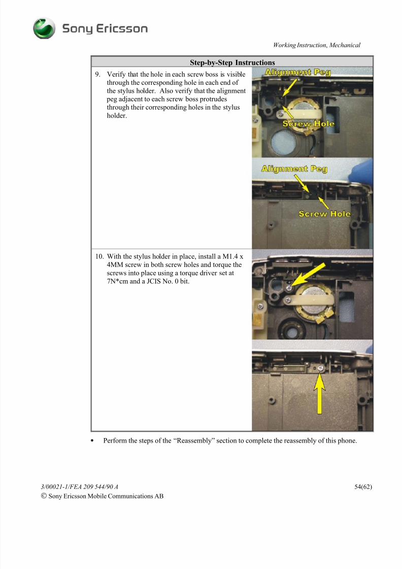
9. Verify that the hole in each screw boss is visible
through the corresponding hole in each end of
the stylus holder. Also verify that the alignment
peg adjacent to each screw boss protrudesthrough their corresponding holes in the stylus
holder.
10. With the stylus holder in place, install a M1.4 x
4MM screw in both screw holes and torque the
screws into place using a torque driver set at
7N*cm and a JCIS No. 0 bit.
• Perform the steps of the “Reassembly” section to complete the reassembly of this phone.
8/4/2019 P910 Working Instructions by Adalbertio
http://slidepdf.com/reader/full/p910-working-instructions-by-adalbertio 55/62
Working Instruction, Mechanical
3/00021-1/FEA 209 544/90 A
Sony Ericsson Mobile Communications AB
55(62)
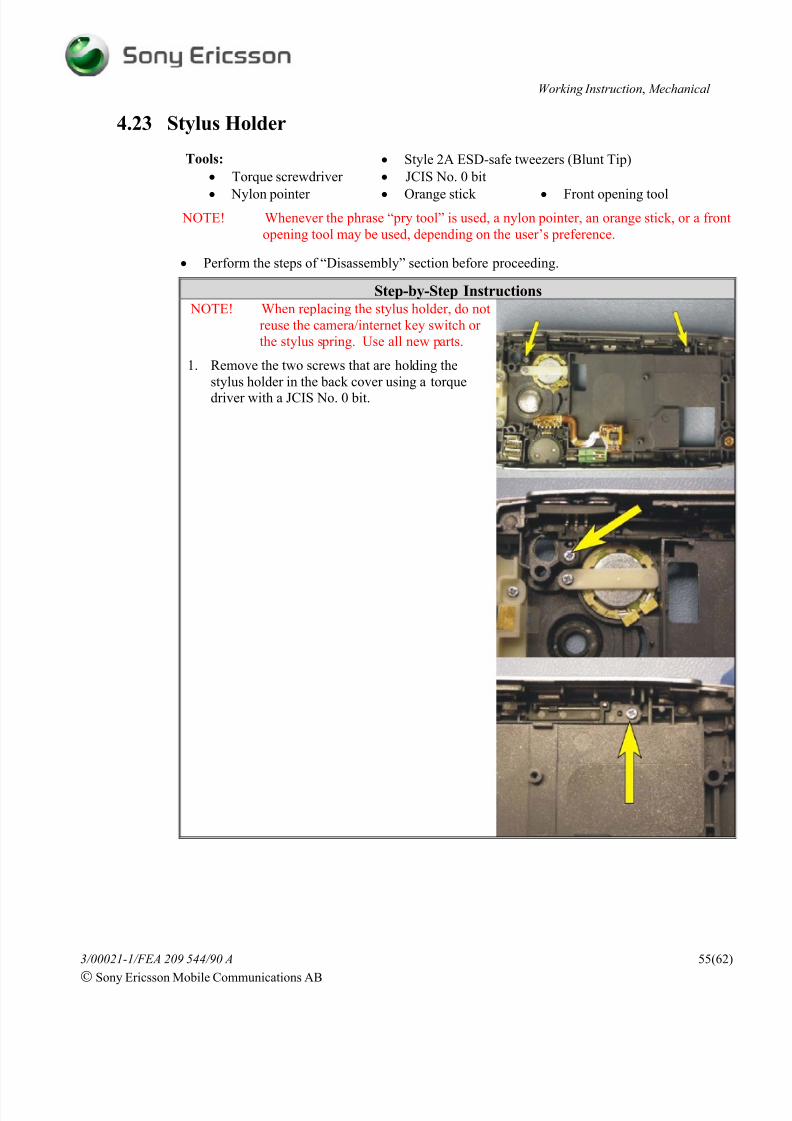
4.23 Stylus Holder
Tools: • Style 2A ESD-safe tweezers (Blunt Tip)
• Torque screwdriver • JCIS No. 0 bit
• Nylon pointer • Orange stick • Front opening tool
NOTE! Whenever the phrase “pry tool” is used, a nylon pointer, an orange stick, or a front
opening tool may be used, depending on the user’s preference.
• Perform the steps of “Disassembly” section before proceeding.
Step-by-Step Instructions NOTE! When replacing the stylus holder, do not
reuse the camera/internet key switch or
the stylus spring. Use all new parts.
1. Remove the two screws that are holding the
stylus holder in the back cover using a torque
driver with a JCIS No. 0 bit.

8/4/2019 P910 Working Instructions by Adalbertio
http://slidepdf.com/reader/full/p910-working-instructions-by-adalbertio 56/62
Working Instruction, Mechanical
3/00021-1/FEA 209 544/90 A
Sony Ericsson Mobile Communications AB
56(62)
Step-by-Step Instructions2. Using a pair of tweezers, lift the end of the stylus
holder near the antenna off of its guide pin and
gently work the stylus holder free from the back
cover and set it aside.
3. Obtain a new stylus holder and a stylus spring.
4. Insert the “L” shaped end of the spring into thehole shown.
5. Position the spring so that its rests in the groove
as shown.

8/4/2019 P910 Working Instructions by Adalbertio
http://slidepdf.com/reader/full/p910-working-instructions-by-adalbertio 57/62
Working Instruction, Mechanical
3/00021-1/FEA 209 544/90 A
Sony Ericsson Mobile Communications AB
57(62)
Step-by-Step Instructions6. Using a pry tool, press the accessible end of the
spring towards the stylus holder so that the long
portion of the spring snaps between the two
catches as shown.
7. Place a piece of adhesive tape in the
camera/internet key switch’s cavity oriented as
shown.

8/4/2019 P910 Working Instructions by Adalbertio
http://slidepdf.com/reader/full/p910-working-instructions-by-adalbertio 58/62
Working Instruction, Mechanical
3/00021-1/FEA 209 544/90 A
Sony Ericsson Mobile Communications AB
58(62)
Step-by-Step Instructions8. Insert a new camera/internet key switch so that
the two round contacts are oriented away from
the stylus holder and the three spring fingers
protrude through the hole in the stylus holder’sswitch cavity.
NOTE! The tips of the three spring fingers
should point away from the stylus
holder if the switch is oriented correctly.
9. Orient the stylus holder so that the screw hole
near each end matches up with their
corresponding screw bosses in the back cover.
10. Work the stylus holder down into its cavity in
the back cover.
NOTE! Be careful not to damage the camera/
internet switch when installing the
stylus holder.

8/4/2019 P910 Working Instructions by Adalbertio
http://slidepdf.com/reader/full/p910-working-instructions-by-adalbertio 59/62
Working Instruction, Mechanical
3/00021-1/FEA 209 544/90 A
Sony Ericsson Mobile Communications AB
59(62)
Step-by-Step Instructions
11. Verify that the hole in each screw boss is visible
through the corresponding hole in each end of
the stylus holder. Also verify that the alignment
peg adjacent to each screw boss protrudesthrough their corresponding holes in the stylus
holder
12. With the stylus holder in place, install a M1.4 x
4MM screw in both screw holes and torque the
screws into place using a torque driver set at
7N*cm and a JCIS No. 0 bit.
• Perform the steps of the “Reassembly” section to complete the reassembly of this phone.

8/4/2019 P910 Working Instructions by Adalbertio
http://slidepdf.com/reader/full/p910-working-instructions-by-adalbertio 60/62
Working Instruction, Mechanical
3/00021-1/FEA 209 544/90 A
Sony Ericsson Mobile Communications AB
60(62)
4.24 Water Indicator Label
Tools:
• ESD-safe tweezers • Lint-free wipes
• Orange stick • Nylon pointer
• Front opening tool
NOTE! Whenever the phrase “pry tool” is used, a nylon pointer, an orange stick, or a front
opening tool may be used, depending on the user’s preference.
• Perform the steps of “Disassembly” section before proceeding.
Step-by-Step Instructions1. Using the flat end of a pry tool, gently remove
the water indicator label.
2. Clean off any adhesive residue in the label area
using alcohol and a lint-free wipe.
3. Obtain a new water indicator label and place the
new label on the circuit board near the battery
connector in the location shown.
4. Apply pressure to the water indicator label so
that a good bond forms between the label and the
circuit board.
• Perform the steps of “Reassembly” section to complete the reassembly of this phone.

8/4/2019 P910 Working Instructions by Adalbertio
http://slidepdf.com/reader/full/p910-working-instructions-by-adalbertio 61/62
Working Instruction, Mechanical
3/00021-1/FEA 209 544/90 A
Sony Ericsson Mobile Communications AB
61(62)
4.25 Label Replacement
Tools:
•ESD-safe tweezers
•Hot air device
• Lint free wipes
• Remove the battery door and the battery as described in the Disassembly section of this
document.
Step-by-Step Instructions
NOTE! This instruction should be used when
exchanging an old label or mounting a
new one.
1. Print a new label.
NOTE! The text must be fully readable and the
barcode must be scannable. NOTE! If one label or less is present on the
phone, proceed to step 3.
NOTE! Heating up the old label(s) with a hot air
device may significantly decrease thedifficult of peeling the labels off.
2. Carefully remove the old labels.
NOTE! Avoid scratching the frame when trying
to get the peeling off of the labels
started.
NOTE! Make sure that all adhesive residue isremoved. Carefully clean off any
residue in the label area with alcohol
and lint free wipes.
NOTE! No more than two labels are allowed
on the battery cavity.
3. Position the new label so that it falls within the
recessed area in the floor of the battery cavity
that is adjacent to the SIM connector. The shape
of the recessed area corresponds to the shape of
the label.
4. Once the label is correctly positioned on thefloor of the battery cavity, carefully smooth the
label into place.
• Install the battery and the battery door as described in the Reassembly section of this
document.

8/4/2019 P910 Working Instructions by Adalbertio
http://slidepdf.com/reader/full/p910-working-instructions-by-adalbertio 62/62
Working Instruction, Mechanical
5 Revision History
Rev. Date Changes / CommentsA 2004-08-13 • Initial Release