P8000 Power AT -102 - Infiniti · User Guide Contents P8000 Power AT -102 ... ESAOTE P8000 Power...
160
i Contents User Guide P8000 Power AT-102 ECG and Spirometry Unit User Guide Article Number 9740440033 ESAOTE SPA 2003
Transcript of P8000 Power AT -102 - Infiniti · User Guide Contents P8000 Power AT -102 ... ESAOTE P8000 Power...

i
ContentsUser Guide
P8000 Power AT-102
ECG and Spirometry Unit
User Guide
Artic
le N
umbe
r 974
0440
033
ESAO
TE S
PA 2
003

ii
P8000Power ECG Recorder
DDDDDistributed by:ESAOTE S.P.A
Via Di Caciolle 1550127 Firenze, ItalyTEL: +39 055 4229 1
FAX: +39 055 4229 208
Manufactured by:Schiller AGAltgasse 68
CH-6341 Baar, Switzerland

iii
ContentsUser Guide
P8000Power User Guide
Article Number 9740440033
Revision e
December 2003
Associated Documents
! Physicians Guide to the Interpretation and Measurement Program - Article Number
9740440008
! P8000Power Spirometry Supplement
! P8000Power Service Handbook
! This user guide is also available in other languages
The ESAOTE sales and service centre network is worldwide. For the address of your local
distributor, contact your nearest ESAOTE subsidiary. In case of difficulty a complete list of all
distributors and subsidiaries is provided on our internet site:
http://www.ESAOTE.com

iv
P8000Power ECG Recorder
Intended Use
The P8000Power is a 12-channel, ECG device used for the recording, analysis andevaluation of ECG Recordings. Recordings made with the P8000Power can be used asa diagnostic aid for heart function and heart conditions. The P8000Power is designed forindoor use and can be used for all patients of both sexes, all races, and all ages.
Physician`s Responsibility
The P8000Power ECG Unit is provided for the exclusive use of qualified physicians orpersonnel under their direct supervision. The numerical and graphical results and anyinterpretation derived from a recording must be examined with respect to the patient`soverall clinical condition. Patient preparation and the general recorded data quality, whichcould effect the report data accuracy, must also be taken into account.
It is the responsibility of the physician to make the diagnosis or to obtain expert opinionon the results, and to institute correct treatment if indicated.
FEDERAL LAW IN THE USA RESTRICTS THIS DEVICE TO SALE BY ORON THE ORDER OF A PHYSICIAN

v
ContentsUser Guide
Declaration of Conformity
Electrocardiograph: ESAOTE P8000 Power
We, the undersigned, hereby declare that the medical device (classe II a) specifiedabove conforms with the Essential Requirements listed in Annex I, of EC Directive93/42/EEC
This declaration is supported by:
TÜV Product Service GmbH, Management Service, D – 80339 Munich
Certificate of approval No:
12 100 13897 DIN EN ISO 9001:2000
Q1Z 01 03 41505 002 DIN EN ISO 9001:1994 / DIN EN 46001:1996
G1 01 03 41505 001 Annex II, Section 3 of the Directive 93/42/EEC MedicalDevices
Valid date 02/2004.
Baar (Switzerland), 26.03.02
Markus BütlerQuality Assurance Manager

vi
P8000Power ECG Recorder
Intended Use ivPhysician`s Responsibility ivDeclaration of Conformity v
Terms of Warranty xiiDisposal Instructions and Battery Care xiii
Safety Notices xivOperational Precautions xivPrecautions for Operation with other Devices xvMaintenance Precautions xviExtra Precautions for Spirometry xvii
Symbols and Conventions Used in this User Guide xviiiWarnings and Cautions xviiiGeneral Symbols xix
Section 1 Getting Started 1.1Initial Preparation 1.2
Location 1.2Introduction 1.4
Standard Features 1.4Optional Features 1.4Operating Philosophy Overview 1.5Initiating Functions or Tasks 1.5
Main Components of the P8000Power 1.6Back Panel 1.7Power Supply 1.8
Switching On and Off 1.8Changing a Mains Fuse 1.9Potential Equalisation 1.9
Keypad 1.10LCD Screen 1.12Entering Patient Data 1.14
P8000PowerUser Guide
Contents

vii
ContentsUser Guide
Section 2 Resting ECG 2.1Electrode Placement 2.2
Resting ECG 2.2Electrode Placement 2.3Further Lead Combinations 2.4
Nehb Leads 2.4Further Lead Combinations 2.5
Electrode Positions for Additional Leads 2.5Electrodes and Neutral ElectrodesIdentification and Colour Code 2.6Skin/Electrode Resistance 2.7
High Electrode Resistance Indication 2.7Electrode (and Patient cable) Check (Lead Test) 2.7
Modes of Operation and Procedural Overview 2.8Automatic Mode 2.9Manual Mode 2.11Screen (and Manual Printout) Settings 2.12Memory 2.14Transmitting the Recordings 2.16
Safety Notices when Transmitting 2.16Line Transmission 2.16Modem Transmission 2.17
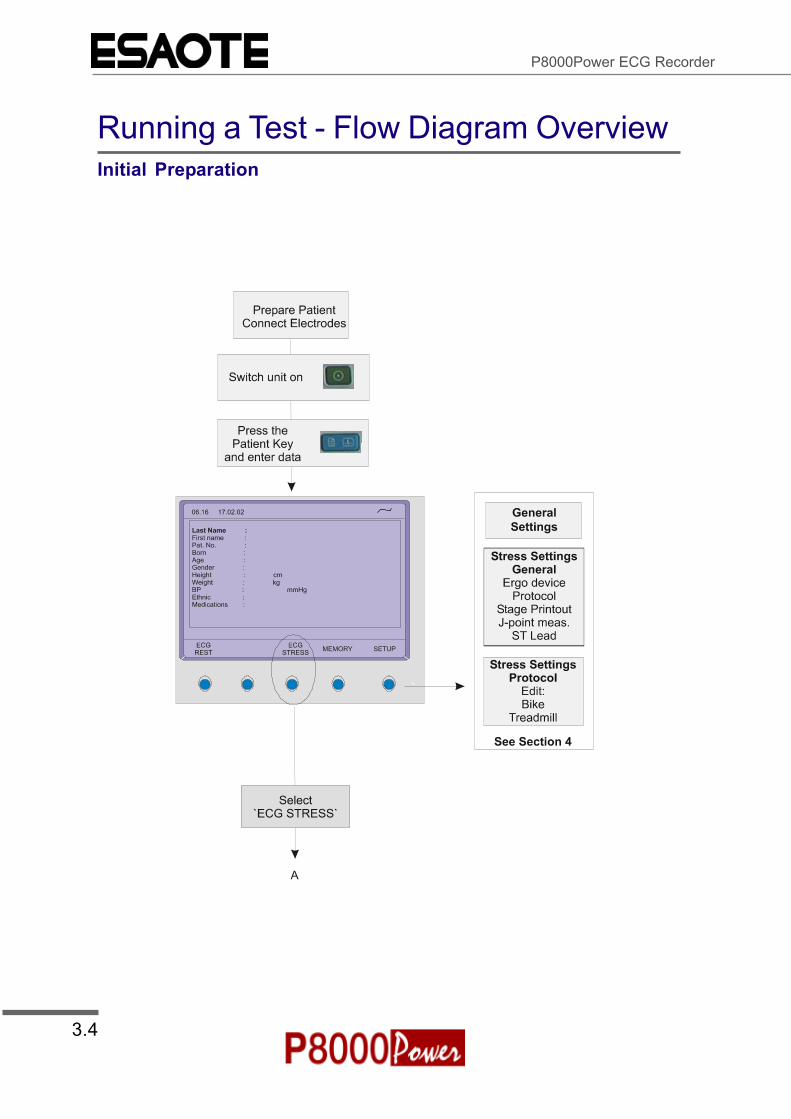
Section 3 Exercise ECG 3.1Warnings 3.2Running a Test - Flow Diagram Overview 3.4
Initial Preparation 3.4Define Ergo Device and Select Protocol 3.5Take a Resting ECG and Start Exercise Test 3.6Enter Recovery Stage and End Test 3.7
Exercise Electrode Placement 3.8Exercise ECG 3.9
Running the Test 3.10Starting the Test 3.10
During The Test 3.13Changing the Display Lead Group on thescreen and Manual Printout 3.13Changing the Display Sensitivity and Speedon the screen and Manual Printout 3.13Switching the Filter on / off 3.13Advancing to the next Stage in the Protocol/Holding the Current Stage 3.14ST Elevation and Slope 3.14Obtaining Extra Printout(s) During the Test 3.15Entry of Blood Pressure Values 3.16

viii
P8000Power ECG Recorder
Section 4 Setup 4.1Navigating in the Setup Screens 4.2ECG Settings 4.3
Auto Mode Format 1 and 2 4.4ECG Printout 4.4Average Cycles 4.5Rhythm Leads 4.5Measurements, Markings and Interpretation 4.5Filters 4.6Baseline filter 4.6Myogram filter 4.7Mains filter 4.7Baseline Stabiliser (SBS) 4.7Smoothing Filter (SSF) 4.7Interpretation 4.8Leads 4.9Defining Lead Sequence & Printout 4.9Auto Storage 4.10
Stress Settings 4.11General Settings 4.12Selecting the ERGO Device 4.12Blood Pressure Entry 4.12Selecting the Default Test Protocol 4.13Defining the Stage Printout Format 4.13ST Amplitude Lead 4.13Defining / Editing Exercise Protocols 4.14Bike Protocol 4.14Factory Programmed Bicycle Protocols 4.15Treadmill Protocol 4.15Factory programmed Treadmill Protocol 4.15Bruce 4.15
System Settings 4.16Unit 4.17User Identification (User ID) 4.17Date and Time 4.17Language 4.18Startup Screen 4.18Paper Mode 4.18Communication 4.19Test and Information 4.20Obtaining a printout of all current settings 4.21Communications Test 4.23Installing New Software Options (Upgrade) 4.23Updating the Software 4.24Default Settings 4.25Unit Defaults Table 4.26

ix
ContentsUser Guide
Section 5 Maintenance, Fault-Finding and TechnicalData 5.1Care & Maintenance 5.2
Self-test 5.2Communication (RS-232) Test 5.212 Monthly Check 5.2Cleaning the Casing 5.3Cleaning the Patient Cable 5.3Cleaning the Thermal Print Head 5.3
Replacing the Recording Paper 5.4Thermal Paper Handling 5.5
Fault-Finding 5.6Accessories and Disposables 5.8Technical Data 5.9
System: 5.9Safety Standards: 5.10Technical Data for ECG: 5.10Technical Data for Spirometry (Option): 5.11Standard 5.13Configurations 5.13
Annex A - Section 1 - Taking a Spirometry TestIntended Use A.1.2
Introduction A.1.3SP-260 Sensor - Changing the Filter A.1.4SP-250 Sensor - Changing the Mouthpiece A.1.6Procedure Overview A.1.7
Notes on Entering Patient Data A.1.8Screen Information A.1.11Printout A.1.12
Pulmonary Test Overview A.1.13Forced Vital Capacity (FVC) A.1.13Slow Vital Capacity (SVC) A.1.14Maximum Voluntary Ventilation (MVV) A.1.14
Post-Medication Tests A.1.15Best and Predicted Values, and Ethnic Influences A.1.16
Definition of Best A.1.16Predicted Values A.1.16Ethnic Influences on Predicted Values A.1.16
Spiro Settings A.1.17Printout A.1.18Device A.1.19
Calibration A.1.20Calibration Procedure A.1.22
Accessories & Ordering A.1.23

x
P8000Power ECG Recorder
Spirometry Tips - How To Do It and CommonPitfalls and Problems A.1.24
How to Do It A.1.24FVC A.1.25FEV1 A.1.26Patient-Related Problems A.1.27
Annex A - Section 2 - Definitions and ReferencesMeasured Values A.2.2Diagnosis International A.2.4Diagnosis American A.2.5
Categorisation of Airway Obstruction A.2.5Categorization of Chest Restriction A.2.6Ratio of Post (Pre / Post) A.2.7
Ethnic Influences on Norm Values A.2.8Norm Values A.2.9Norm Values for Countries Outside the USA and Canada A.2.10
ECCS Values A.2.10Quanjer & Tammeling Comparisons A.2.11Austrian Standard Values A.2.11Swedish Standards (Berglund) A.2.12Finnish Standards A.2.12Indian Equations A.2.13
Norm Values for USA and Canada A.2.14Morris Norm Values A.2.14Crapo Norm Values A.2.15Morris and Crapo Norm Values for Children A.2.16Knudson Norm Values A.2.17Knudson 76 Norm Values A.2.18Composite Norm Values A.2.19Polgar Norm Values A.2.20

xi
ContentsUser Guide
Terms of WarrantyThe ESAOTE P8000Power is warranted against defects in material and manufacture for theduration of one year (as from date of purchase). Excluded from this guarantee is damagecaused by an accident or as a result of improper handling. The warranty entitles freereplacement of the defective part. Any liability for subsequent damage is excluded. The warrantyis void if unauthorized or unqualified persons attempt to make repairs.
In case of a defect, send the apparatus to your dealer or directly to the manufacturer. Themanufacturer can only be held responsible for the safety, reliability, and performance of theapparatus if:
assembly operations, extensions, readjustments, modifications, or repairs are carried outby persons authorized by him, and
the ESAOTE P8000Power and approved attached equipment is used in accordance withthe manufacturers instructions.
THERE ARE NO EXPRESS OR IMPLIED WARRANTIES WHICH EXTEND BEYOND THEWARRANTIES HEREINABOVE SET FORTH. ESAOTE MAKES NO WARRANTY OFMERCHANTABILITY OR FITNESS FOR A PARTICULAR PURPOSE WITH RESPECT TO THEPRODUCT OR PARTS THEREOF.
This equipment has been tested and found to comply with the limits for a class A digital device,pursuant to both Part 15 of the FCC (Federal Communications Commission) Rules and theradio interference regulations of the Canadian Department of Communications. These limits aredesigned to provide reasonable protection against harmful interference when the equipment isoperated in a commercial environment. This equipment generates, uses and can radiate radiofrequency energy and, if not installed and used in accordance with this instruction manual, maycause harmful interference to radio communications. Operation of this equipment in aresidential area is likely to cause harmful interference in which case the user will be required tocorrect the interference at his own expense.

xii
P8000Power ECG Recorder
Disposal Instructions and Battery Care
DO NOT DISPOSE OF THE BATTERY BY FIRE OR INCINERATOR - DANGER OFEXPLOSION
DO NOT OPEN THE BATTERY CASING - DANGER OF ACID BURN
Only dispose of the battery in official recycling centres or municipally approved areas.
Units no longer required can be disposed of in municipally approved recycling centres.
xiii
ContentsUser Guide
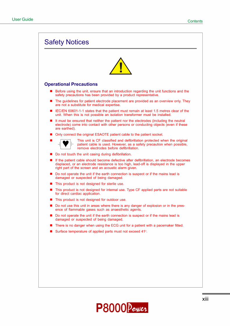
Safety Notices
Operational PrecautionsBefore using the unit, ensure that an introduction regarding the unit functions and thesafety precautions has been provided by a product representative.
The guidelines for patient electrode placement are provided as an overview only. Theyare not a substitute for medical expertise.
IEC/EN 60601-1-1 states that the patient must remain at least 1.5 metres clear of theunit. When this is not possible an isolation transformer must be installed.
It must be ensured that neither the patient nor the electrodes (including the neutralelectrode) come into contact with other persons or conducting objects (even if theseare earthed).
Only connect the original ESAOTE patient cable to the patient socket.
This unit is CF classified and defibrillation protected when the originalpatient cable is used. However, as a safety precaution when possible,remove electrodes before defibrillation.
Do not touch the unit casing during defibrillation.
If the patient cable should become defective after defibrillation, an electrode becomesdisplaced, or an electrode resistance is too high, lead-off is displayed in the upperright part of the screen and an acoustic alarm given.
Do not operate the unit if the earth connection is suspect or if the mains lead isdamaged or suspected of being damaged.
This product is not designed for sterile use.
This product is not designed for internal use. Type CF applied parts are not suitablefor direct cardiac application.
This product is not designed for outdoor use.
Do not use this unit in areas where there is any danger of explosion or in the pres-ence of flammable gases such as anaesthetic agents.
Do not operate the unit if the earth connection is suspect or if the mains lead isdamaged or suspected of being damaged.
There is no danger when using the ECG unit for a patient with a pacemaker fitted.
Surface temperature of applied parts must not exceed 41o.
Ì

xiv
P8000Power ECG Recorder
Safety Notices
Precautions for Operation with other DevicesUse only accessories and other parts recommended or supplied by ESAOTE.Use of other than recommended or supplied parts may result in injury, inaccurateinformation and/or damage to the unit.
Accessory equipment connected to the analogue and digital interfaces must becertified according to the respective IEC standards (e.g. IEC/EN 60950 for dataprocessing equipment and IEC/EN 60601-1 for medical equipment). Furthermoreall configurations shall comply with the valid version of the system standard IEC/EN 60601-1-1. Everybody who connects additional equipment to the signal inputpart or signal output part configures a medical system, and is therefore responsi-ble that the system complies with the requirements of the valid version of thesystem standard IEC/EN 60601-1-1. If in doubt, consult the technical servicedepartment or your local representative.
Externally connected units must use the same common earth.
Externally connected units must use an original ESAOTE interface cable.
If several units are coupled, there is a danger of summation of leakage currents.When two or more units are coupled together, an isolation transformer must beused in the mains supply.
The unit complies with EMC regulations for medical products which affordsprotection against emissions and electrical interference. However, special caremust be exercised when the unit is used with high frequency equipment.
There is no danger when using the ECG unit simultaneously with other electricalstimulation equipment. However, the stimulation units should only be used at asufficient distance from the electrodes. In case of doubt, the patient should bedisconnected from the recorder.
To avoid possible interference from the Ergometer when carrying out an exercisetest, it is recommended that both the P8000 and the Ergometer are connected tothe same common ground.
If the P8000 is part of a medical system, the original ESAOTE patient cable mustonly be used with, and connected to, the patient connector on the P8000.

xv
ContentsUser Guide
Safety Notices
Maintenance PrecautionsDo not use high temperature sterilisation processes (such as autoclaving). Do not use e-beam or gamma radiation sterilisation.
Do not use solvent or abrasive cleaners on either the unit or cable assemblies.
To prevent electric shock do not disassemble the unit. No serviceable parts inside. Referservicing to qualified personnel only.
Before cleaning and to isolate the mains power supply, switch the unit off and disconnectfrom the mains by removing the plug.
Do not, under any circumstances, immerse the unit or cable assemblies in liquid.
The unit is protected by double pole / neutral fusing for continued protection against the risk offire. Replace only with the same fuse type and rating.
xvi
P8000Power ECG Recorder
Safety Notices
Extra Precautions for Spirometry
Sensor SP-250The disposable mouthpiece of the SP-250 spiro sensor is designed for one-time use toeliminate the danger of cross contamination - do not use the mouthpiece for more than onepatient. Do not attempt to clean the mouthpiece.
Sensor SP-260The mouthpiece of the SP-260 spiro sensor is reusable. Thoroughly disinfect the mouthpieceassembly before using for another patient. Replace the filter after every patient - do not usethe filter for more than one patient.
GeneralFor correct predicted values and diagnosis, it is important that all patient data is enteredcorrectly. In particular gender, date of birth, ethnic, height and weight must be entered.
The unit must be calibrated at the beginning of every day, or after a significant change intemperature.
False measurements can result when the sensor is not held vertically - always ensure thatthe sensor is held upright at all times.

xvii
ContentsUser Guide
Symbols and Conventions Used in this User Guide
Warnings and Cautions
General warning applicable to following text and/or chapter. Text set off in this manner indicates thatfailure to follow directions could result in bodily harm or loss of life.
WARNING:
Specific warning applicable to associated instruction. Text set off in this mannerindicates that failure to follow directions could result in bodily harm or loss oflife.
CAUTION:
Specific caution applicable to associated instruction. Text set off in this mannerindicates that failure to follow directions could result in damage to equipment orloss of information

xviii
P8000Power ECG Recorder
Symbols and Conventions Used in this User Guide
General Symbols
NOTE:
Text set off in this manner presents clarifying information, specific instructions,commentary, sidelights, or interesting points of information.
CF Symbol. Unit is classified safe for internal and external use. The paddles at theside indicate that the unit is defibrillation protected when the original ESAOTEpatient cable is used.
Potential Equalisation Point.
The unit /component can be recycled.
Type and approving body.
Ì

1.1
Section 1Getting Started
Article Number 9740440033ESAOTE SPA 2002
User Guide
Section 1
Getting Started
This section contains an introduction to the P8000Power and anoverview of all external connections. It also gives an overview of theoperating philosophy of the P8000Power and an introduction to thebasic functions of the unit.

1.2
P8000Power ECG Recorder
Initial Preparation
The P8000Power requires no special tools for preparation. To commission the P8000Power proceedas follows:
1. Open the box and remove the unit. Store the packaging for reuse if necessary.
2. Place the unit on a suitable work surface.
LocationDo not keep or operate the unit in a wet or dusty environmentAvoid exposure to direct sunlight or heat from other sourcesDo not allow the unit to come in contact with acid vapours or liquidsDo not place the unit in the vicinity of X-ray or diathermy units, large transformers orelectric motors.
3. Connect the mains supply to the mainsconnector on the rear panel of the unit withthe supplied mains cable. The Mains LEDbelow the ON key, will light. Leave theP8000Power connected to the mains for 24hours to fully charge the battery.
ON Key and mains indicator
4. Switch the unit on - the LCD will light and thepatient data screen or ECG acquisitionscreen (see Section 4 - Setup), is displayed.
5. Connect the patient cable to the patientconnector on the right side panel.

1.3
Section 1Getting Started
Article Number 9740440033ESAOTE SPA 2002
User Guide
Initial Preparation
6. Press the paper tray release key toopen the paper tray.
7. Insert the thermal print paper andagain press the paper tray key toreturn the paper tray - full detailsare given in Section 5.
8. If an external monitor is to beconnected, connect it to the VGAconnector on the rear panel with thecable supplied. If an external printer issupplied, connect it to the printerconnector..
CAUTION
To prevent the possibility of leakage current when the external printer is con-nected, always ensure that the mains lead, or the potential equalisation (next tothe mains connector), is attached to the P8000Power.

1.4
P8000Power ECG Recorder
Introduction
The ESAOTE P8000Power is a 12-channel ECG unit designed to record, display, and analyse restingECGs (exercise ECGs can also be recorded). The unit has been extensively researched to give anergonomic, clear interface that`s easy to use without compromising functionality. The P8000Power hasthe following features:
Standard FeaturesAlphanumeric keypad and dedicated soft key interface for easy, user friendly operation.
Storage and transmission facilities for recordings.
Integral full size thermal quality printer with various user defined print format options.
VGA socket for connection of an external monitor (ECG traces only).
Optional FeaturesExcercise ECG with interface for control of digital ergometers and treadmills.
External deskjet printer.
ECG Interpretation including measurements and average cycles with automatic and manualprintout of the recording.
Sensor for spirometry recording (software is standard and pre installed on the P8000).
Two sensors are available; the SP-260 sensor with a disposable filter, and the SP-250 sensorwith a disposable mouthpiece assembly. When using the SP-260 sensor, the filter must bechanged and the mouthpiece sterilised after every patient. With the SP-250 sensor, themouthpiece assembly is replaced complete removing the need to sterilise after every patient.

1.5
Section 1Getting Started
Article Number 9740440033ESAOTE SPA 2002
User Guide
Introduction
Operating Philosophy OverviewThere are broadly four types of data display as follows
Data Acquisition and In this screen the real-time ECG is displayed.ECG Recording Screen From this screen a continuous printout can be initiated and/or an
auto recording can be made. In auto mode 10 seconds of ECG datais analysed and averaged and the results given on a printout. Theformat and data of an auto mode printout is independent of thescreen display, and is defined in the setup screens. (See section 4).
An auto mode recording can also be stored in the memory for laterprint or transmission.
Memory Screen In this screen stored recordings can be accessed.
Patient Data Screen Patient data entry via the keypad.
Data Entry and Setup In these screens all system settings, resting and exercise ECGsettings, and spiro settings are made.
Initiating Functions or TasksMost functions and tasks are initiated by the 5softkeys situated immediately below the LCD.The function of the softkeys varies accordingto the screen displayed and is displayed onthe LCD immediately above the key itself.
During data acquisition, further dedicatedfunction keys are provided to make an automode recording (START) and to stop amanual printout (STOP). The top line of thealphanumeric keypad, additionally enablesdirect settings of lead group, trace speed andsensitivity, filter on/off and other functions, forboth the real-time display and (manual)printout.

1.6
P8000Power ECG Recorder
Main Components of the P8000Power
1. Keypad and dedicated function keys
2. Patient cable connector
3. RS-232 for any of the following:° connection of an ergo device° connection of a spiro sensor° connection of a modem or a PC for export of stored recordings
4. Softkey control
5. LCD Display.
32 4 51

1.7
Section 1Getting Started
Article Number 9740440033ESAOTE SPA 2002
User Guide
Back Panel
1. VGA connector for the connection of an external monitor (option)2. LPT connector for the connection of an external printer3. Master Reset4. Potential equalisation stud
5. Mains connector (with fuse below)
CAUTION:
All externally connected hardware must be approved by ESAOTE. Connection ofany hardware not approved by ESAOTE is at the owner`s risk. The unit guaran-tee may also be invalid.
2 3 4 51

1.8
P8000Power ECG Recorder
Power Supply
The mains connection is on the rear of the unit.
The power supply voltage is factory set for 220-240V (nom. 230V) working. The setting is indicatedby the indented metal strip on the fuse panel. If the voltage needs to be changed for 100-115V (nom.110V) working, consult the quick reference sheet.
Switching On and OffThe P8000Power is switched on with the ON key (right key) and off with the OFF key. These keys aresituated on the top right of the keypad.
The mains indicator lamp on the keypad is always lit whenthe unit is connected to the mains supply.
The unit can either be operated from the mains supply or from the built-in rechargeable battery. Thepower source is indicated on the top line of the LCD. When mains is connected a mains symbol isdisplayed. When the unit is running on battery power a battery symbol is displayed
Power Indicator symbol
The internal battery provides power for up to 3 hours.The Battery indicator blinks when the battery capacity islimited.
To recharge the battery, connect the apparatus to themains supply by means of the supplied power cable. Atotally discharged battery requires approximately:° 15 hours to be fully recharged° 7 hours to be 90% recharged° 3 hours to be 60% chargedThe unit can remain connected to the mains supplywithout damage to either the battery or the unit.
NOTE:
When working from battery power, the unit is automatically switched off after 5minutes (30 seconds if battery capacity is limited) if no key is pressed.

1.9
Section 1Getting Started
Article Number 9740440033
ESAOTE SPA 2002
User Guide
Power Supply
Changing a Mains Fuse
WARNING
Before changing a fuse, isolate the mains supply by removing the plug from thewall socket.
CAUTION
Always replace fuses with the correct rating i.e. 2x200mAT for 230V, or 2x315mATfor 110V.
To change a fuse press the retaining lug in the middle of the fuse panel (situated below the mains
connector on the back panel). Remove the fuse panel and replace the fuse(s). Click the fuse panel back
in position. See quick reference sheet supplied for full details.
Potential Equalisation
The potential equalisation stud at the rear of the unit can be used to equalise the ground potential of the
P8000Power to that of all mains powered equipment in the vicinity. Use the hospital or building common
ground.
CAUTION:
To avoid possible interference from the Ergometer when carrying out an exer-cise test, it is recommended that both the P8000Power and the Ergometer areconnected to the same common ground.
To prevent the possibility of leakage current when an external printer is con-nected, always ensure that the mains lead, or the potential equalisation (next tothe mains connector), is attached to the P8000Power

1.10
P8000Power ECG Recorder
Keypad
4 7 8 9 10 11 12 13 14 15
16
1
2
3
5 6
17

1.11
Section 1Getting Started
Article Number 9740440033ESAOTE SPA 2002
User Guide
Keypad
1. Softkeys - the function of these keys changes depending on the screen displayed. The function ofthese keys is shown on the screen above the keys. If nothing is written above a softkey, it has nofunction for the current screen.
2. Auto Mode recording (in Auto mode 1).
Press the SHIFT followed by the AUTO key (2) for auto mode 2.
3. STOP printout / confirm (new) setting
4. Open / Close paper tray (to replace thermal printing paper)
5. The top figures on the number keys `1` and `2 ` (designated < and >), change the lead groupdisplayed on the screen, forward and backward resp.
6. Auto sensitivity key - automatically sets the ECG printout sensitivity ( in AUTO mode only) to thebest setting for the signal strength (5mm/mV or 10mm/mV)
7. The top figures on the number keys designated 5, 10, and 20 set the sensitivity of the ECG bothon the screen and on the (manual) printout. The sensitivity is 5, 10 or 20 mm / mV.
8. The top figures on the number keys designated 5/10, 25, and 50 set the speed of the ECG bothon the screen and on the (manual) printout. The speed on the screen can only be set to 25 or 50mm/s. The speed of the manual printout can be 5, 10, 25 or 50 mm/s. The 5 and 10 mm/ssettings are both on the same key which toggles the two speeds.
9. Inserts a 1mV reference marker on the screen and printout. Recentres the trace.
10. Toggles the QRS beeper ON/ OFF
11. Myogram filter ON / OFF. The cutoff frequency can be user defined in `Setup`.
12. Patient data key. Press this key to enter a new patient or modify the data for the current one.
NOTE:
The patient data screen, or the ECG screen is the first screen displayed on initalswitch on. This is set for user prefernece in the system settings (Section 4)
13. Delete last typed character.
14. ON / OFF Keys
15. Mains Indicator - lit when mains connected.
16. Press the function key (17) and the UP/DOWN arrows to adjust screen contrast.
When entering patient data use the LEFT/RIGHT arrow keys to move the cursor in the data field.Use the UP/DOWN arrow keys to go up/down to the next data entry
17. Function Key. When pressed before another key, initiates the second function of that key
For example, second letters on the keypad - è, é, ç, ø @ etc., are entered by holding the functionkey before pressing the letter key.

1.12
P8000Power ECG Recorder
LCD Screen
The display will vary according to the current task being carried out. In all screens however, the top andbottom lines always display the same information: the top line displays system information, and thebottom line always gives the softkey options.
The following is an example of a typical resting ECG screen.
Items 1, 2 and 3 are in the same position for all screens.1. Top line - time, date, patient name, and current power source - mains ( ), or battery ( ). When
battery capacity is limited the battery symbol flashes.2. Softkey designation. Pressing the key below the text carries out the function indicated. The
options available will change according to the screen displayed.3. Data acquisition area or data entry area.
3
56789
10
41
2

1.13
Section 1Getting Started
Article Number 9740440033ESAOTE SPA 2002
User Guide
LCD Screen
Items 4 to 10 are specific for ECG acquisition only:4. Current Heart Rate (averaged over 4 beats and refreshed every 2 seconds). The HR is also given
on a manual printout. Note that with an auto mode printout the HR is averaged over the full 10seconds of the recording.
5. Electrode connections - when an electrode indication flashes it indicates that the electroderesistance is too high. The electrode(s) must be reapplied.
6. Sensitivity - 5, 10 or 20 mm/mV. Change the sensitivity with the keys 3 (auto), 4, 5 and 6. An `A` inthis box indicates that automatic sensitivity is selected (auto mode printout only).
7. Speed - 25 or 50 mm/s. Change the speed with the keys 8 and 9.8. Lead indication (leads currently displayed on the screen). Change the lead group with the < and
> keys on the keypad.9. Myogram Filter indication - 'Filter ON' or 'Filter OFF'. The filter is applied with the filter key.
Note: the frequency of the filter cutoff is defined in Section 4 Setup.
10. Area for system messages or instructions.

1.14
P8000Power ECG Recorder
Entering Patient Data
In this screen a new patient can be entered, or a the details of a selected patient can be modified. Pressthe patient data key.
Last Name Enter patients name (maximum 20 characters)
First Name Enter patients first name (maximum 20 characters)
Pat. No. The patient number is an easily identifiable short form of identifying a patient - amaximum of 20 characters can be entered.
Born Enter patient`s date of birth dd-mm-yy
Only the patients year of birth need be entered (2 or 4 digits), - patient age iscalculated to the nearest year. To calculate the age precisely, the day, month andyear (2 or 4 digits) must be entered.
Gender Enter the patient`s sex - M or F
Weight Enter patient`s weight 0.5..250kg
Height Enter patient`s height 20..250cm
BP Enter the patient`s systolic (or diastolic) blood pressure.
Ethnic The setting made here is mainly used by the Spiro option when calculating normvalues. Enter B (Black) or (W) White.
Medication Up to 23 characters can entered for medication notes
When all entries are made, press the softkey `menu` to confirm the entered data.

2.1
Section 2Resting ECG
Article Number 9740440033ESAOTE SPA 2002
User Guide
Section 2
Resting ECG
This section contains all the information required to make a restingECG Recording.

2.2
P8000Power ECG Recorder
Electrode Placement
Resting ECG
Note: The colours shown here are according to Code 1 (European) requirements. The equivalent code2 colours are given on Page 2.6

2.3
Section 2Resting ECG
Article Number 9740440033ESAOTE SPA 2002
User Guide
Electrode Placement
A minimal resistance between skin and electrode is required to obtain the best ECG signal and ensurethe highest quality ECG recording. Therefore please note the following points:
Ensure that the patient is warm and relaxed.
Shave electrode area before cleaning.
Thoroughly clean the area with alcohol.
When applying the electrodes, ensure that a layer of gel is between the electrode and the skin.
Place the C4 electrode first - in the 5th intercostal space (ICS) so that it lines up approximatelywith the middle of the clavicle.
Then place:
° C1 in the 4th ICS parasternal right
° C2 in the 4th ICS parasternal left
° C3 between, and equidistant to, C4 and C2
° C6 on the patient`s side and aligned with C4
° C5 between, and equidistant to, C4 and C6
The electrode resistance can be checked in the recording screen - see page 2.7.
Note: When making an ECG with a child it is sometimes physically difficult to place all electrodes.When this is the case electrode V4 can be placed on the right side of the chest.
WARNING
During the ECG recording, ensure that neither the patient nor the leadingparts of the patient connection nor the electrodes (including the neutralelectrodes) come in contact with other persons or conductive objects, evenwhen these are earthed..
2.4
P8000Power ECG Recorder
Further Lead Combinations
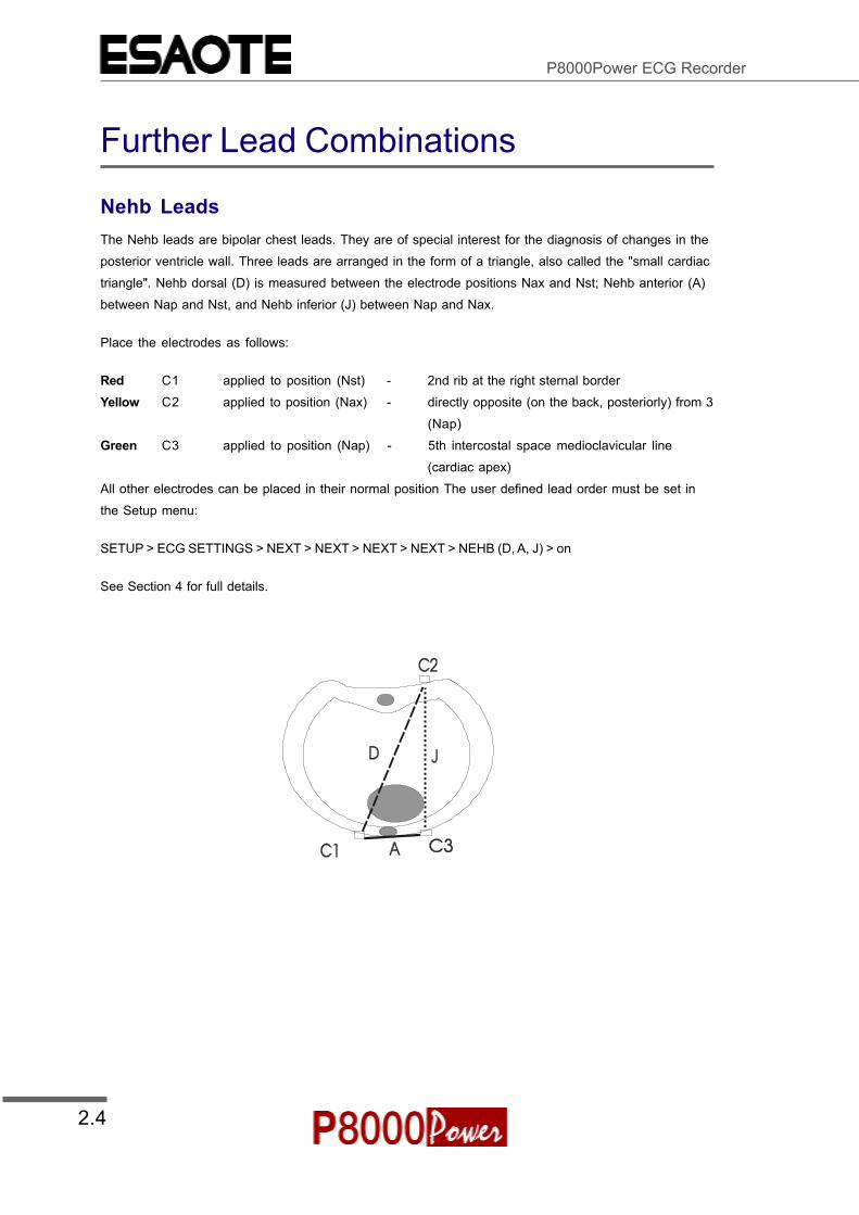
Nehb LeadsThe Nehb leads are bipolar chest leads. They are of special interest for the diagnosis of changes in theposterior ventricle wall. Three leads are arranged in the form of a triangle, also called the "small cardiactriangle". Nehb dorsal (D) is measured between the electrode positions Nax and Nst; Nehb anterior (A)between Nap and Nst, and Nehb inferior (J) between Nap and Nax.
Place the electrodes as follows:
Red C1 applied to position (Nst) - 2nd rib at the right sternal borderYellow C2 applied to position (Nax) - directly opposite (on the back, posteriorly) from 3
(Nap)Green C3 applied to position (Nap) - 5th intercostal space medioclavicular line
(cardiac apex)All other electrodes can be placed in their normal position The user defined lead order must be set inthe Setup menu:
SETUP > ECG SETTINGS > NEXT > NEXT > NEXT > NEXT > NEHB (D, A, J) > on
See Section 4 for full details.

2.5
Section 2Resting ECG
Article Number 9740440033ESAOTE SPA 2002
User Guide
Further Lead Combinations
Electrode Positions for Additional LeadsThe clips from the chest electrodes C1 through C3 have to be removed and connected to the electrodesC7 through C9 placed on the patients back in the appropriate positions.
All other electrodes can be placed in their normal position The user defined lead order must be set inthe Setup menu:
SETUP > ECG SETTINGS > NEXT > NEXT > NEXT > NEXT > posteriorand precordials options. Set on or off to display and print the lead groupusing the lead group keys during data acquisition:
See Section 4 for full details.
NOTE:The additional leads C7 through C9 can only be recorded in manual mode.

2.6
P8000Power ECG Recorder
Electrodes and Neutral ElectrodesIdentification and Colour Code
The electrode placements shown in this handbook are labelled with the colours according to Code1 requirements. The equivalent Code 2 colours are given below.
CODE 1 (Usually European) CODE 2 (Usually American)
System Electrode Colour Electrode ColourIdentifier Code Identifier Code
R Red RA WhiteLimb L Yellow LA Black
F Green LL Red
C White V BrownC1 White/Red V1 Brown/Red
Chest C2 White/Yellow V2 Brown/Yellowaccording C3 White/Green V3 Brown/Greento Wilson C4 White/Brown V4 Brown/Blue
C5 White/Black V5 Brown/OrangeC6 White/Violet V6 Brown/Violet
I Light blue/red I Orange/redPosition E Light blue/yellow E Orange/yellowaccording C Light blue/green C Orange/greento Frank A Light blue/brown A Orange/brown
M Light blue/black M Orange/blackH Light blue/violet H Orange/violet
F Green F Green
Neutral N Black RL Green

2.7
Section 2Resting ECG
Article Number 9740440033ESAOTE SPA 2002
User Guide
Skin/Electrode Resistance
High Electrode Resistance IndicationIf an electrode resistance is too high for a good recording, or an electrode becomes dislodged during a recording,the electrode indication flashes on the screen and an audible beep is heard. The electrode(s) must be reapplied.
Electrode (and Patient cable) Check (Lead Test)To check the electrode resistance and the integrity of the cable, press the LEAD TEST key from the data acquisitionscreen: The following is displayed:
LEAD TEST (mV)
R-89 C1 -98 C4 -72
L-102 C2 -78 C4 -121
C3 -109 C6 -96
This gives electrode dc offset and is the voltage drop in the patient cable. It can indicate any faults in the patientcable or patient electrode. The value given is the dc voltage between the left leg electrode and all other electrodes.The measurements obtained will indicate any cable short circuits or open circuits. The measured voltage value willdepend on where the electrodes are connected. The voltage readings that can be expected are as follows:
With patient connected (good connection, low resistance) - ± 100mV. An offset of up to +300mV will give anacceptable recording.
With patient simulator connected - ± 20 mV - this will depend on the patient simulator used and must betaken as a flexible measurement.
With all electrodes shorted together: - ± 20 mV
No patient cable connected: -350 to -500mV

2.8
P8000Power ECG Recorder
Modes of Operation and ProceduralOverview

2.9
Section 2Resting ECG
Article Number 9740440033ESAOTE SPA 2002
User Guide
Automatic Mode
Two, user defined automatic mode formats are available. The following can be programmed freely foreach of the 2 formats before recording:
Lead Format
Chart Speed
With the optional interpretation program it is also possible to select the rhythm lead(s),measurement table, average cycles with optional markings and interpretation statements for theprintout.
For further information and to define the auto formats see Section 4 `Setup`.
To start an automatic ECG recording in Auto Mode Format 1, press the START key.
To start the automatic ECG recording in Auto Mode Format 2, press the SHIFT key followed by theSTART key.

2.10
P8000Power ECG Recorder
Automatic Mode
After approximately 10 seconds the recording is analysed * and the printout** gives the following:ECG recording of all leads in either Standard or Cabrera format according to selectionSensitivityHeart RateSpeedFilter SettingsTime and DateInterpretation statementsAverage CyclesIntervalsAxisSokolow Index (ECG index for hypertrophy)Detailed Measurement Table
The softkey options change at the end of the recording toenable you to save the recording*** or to obtain an extracopy. When a recording has been saved, it remainsstored by the P8000 until deleted, even when the unit isswitched off. Accessing recordings in the memory isdetailed on page 2. 14 et. seq.
Notes:
* During ECG Acquisition the message `RESTING ECG BEING TAKEN` is displayed. If the P8000 cannotdiscern a trace, the message `QRS NOT DETECTED` is displayed. If the interpretation program detectsan abnormality, the message `UNUSUAL ECG` is displayed.
** When an external printer is connected and switched on, the printout is automatically directed to theexternal printer. When the external printer is unconnected or switched off, the P8000 automaticallyswitches to the internal thermal printer.
*** ECGs can also be saved automatically - see ECG settings, Section 4

2.11
Section 2Resting ECG
Article Number 9740440033ESAOTE SPA 2002
User Guide
Manual Mode
Manual mode provides a direct printout of the real-time ECG with full control of parameter selection.
To start the manual recording of a real-time ECG, press the MANUAL printout soft key
To stop the manual recording (printout), press theSTOP key, or the stop softkey
The printout provides you with the following:
° Six (selected) leads with lead identification.
° On the lower edge, the chart speed, user identification and the mains filter setting (50 or 60 Hz)and the Myogram filter cutoff frequency (if filter applied) 25Hz or 35Hz.
° At the top, the heart rate as current average of 4 beats, trace sensitivity, and the time and date
The lead group, the sensitivity, and the speed of the printout are changed using the display/printout keys(see next page).
WARNING
After heavy artefacts or lead off, the indication of the heart rate may not bereliable.
Note:
Manual real-time printout is not available on an external printer because dataformatting protocol for inkjet (and laser) printers is too slow for real time process-ing. When a continuous real-time printout of the ECG is required, it is alwaysprinted on the internal thermal printer.

2.12
P8000Power ECG Recorder
Screen (and Manual Printout) Settings
The following can be freely chosen during data acquisition, for both the display and for a manual printout,using the top line of keys of the keypad:
Lead Group by means of the LEAD FORWARD and LEAD BACKWARD key. The following leadgroups are selectable:
Standard CabreraI, II, III / aVR, aVL, aVF aVL, I, -aVR / II, aVF, IIIV1, V2, V3 / V4, V5, V6 V1, V2, V3 / V4, V5, V6
Additionally, the following lead groups can be viewed when manually set (on) in ECGsettings - SETUP > ECG SETTINGS > LEADS ( see Section 4 for details).
RhythmII, avF, III / V2, V4, V5
Left PosteriorV4, V5, V6 / V7, V8, V9
Right Precordial up to V5rV1, V2, V3 / V3r, V4r, V5r
Right Precordial up to V6rV1, V2, V3r / V4r, V5r, V6r
NehbD, A, J
Sensitivity Select 5, 10 or 20 mm/mV
NOTE:
Auto Sensitivity To reduce the possibility ofoverlapping traces, an auto sensitivity reduction isapplied in Auto Mode (default). This means that theunit detects very large waveform amplitudes andsets the sensitivity for the extremity and/or precordialleads to 5 mm/mV. An `A` by the side of the sensitivityindicates that Auto sensitivity is set. To disable thisfunction, the AUTO SENSITIVITY key (key 3) must bepressed.

2.13
Section 2Resting ECG
Article Number 9740440033ESAOTE SPA 2002
User Guide
Screen (and Manual Printout) Settings
Chart Speed Select speed 5, 10, 25 or 50mm/s
Key 7 is a toggle key - press once and 5 is selected, press a second time and10mm/s is selected.
When the 25 or 50mm/s key is pressed, the same speed is set on both the screenand the (manual) printout. When 5 or 10 mm/s is selected, this affects the manualprintout speed only.
Myogram Filter Switch the filter ON or OFF with the FILTER key:
`FILTER ON` is displayed on the LCD when the filter is switched on and the cutofffrequency is shown at the bottom of the printout. That is 0.05 - 25 Hz, or 0.05 - 35Hz. The cutoff frequency is defined in Section 4 Setup.
Recentering To re-centre the ECG traces, press the 1mV key
QRS Beep To activate / Deactivate the QRS beep, press the QRS key

2.14
P8000Power ECG Recorder
Memory
The memory option allows approximately 45 recordings (depending on size and parameters specifiedwhen the recording was taken) to be stored, edited, printed, and transmitted over the RS-232 interface.When no more recordings can be stored, the message `MEMORY FULL` is displayed. Old recordingsmust be deleted before further recordings can be stored.
Recordings can be automatically saved after a recording has been made (auto save), or you areprompted to save a recording individually after a recording has been made. This setting is defined inECG settings (see Section 4).
Enter the memory from the initial screen.
All recordings are stored in date order.

2.15
Section 2Resting ECG
Article Number 9740440033ESAOTE SPA 2002
User Guide
Memory
Highlight required recording by pressing the up/down softkeys and press the select softkey.
NOTE:
Highlight all recordings by pressing the function key (Fn), followed by key `A`.
When the required recording(s) is(are) highlighted, press the ENTER softkey.
Softkey options then enables you to obtain a printout, to delete the selected recording(s), or to send overthe RS-232 interface to the ARCHIMED data management software.
When Delete is selected, you are prompted to confirm that you wish to delete the selected file(s). Themessage `ERASING` appears in the message box, during the erasing process.
Note: The print settings are defined in Setup and are described in Section 4

2.16
P8000Power ECG Recorder
Transmitting the Recordings
The contents of the memory can be transmitted to the ARCHIMED data management program (orsimilar), using the RS-232 connected directly to the computer, or over the telephone system. Sendingdirectly is termed LINE transmission; sending over the telephone system requires a modem and thisform of sending is termed MODEM.
When Transmit is selected, the message `TRANSMITTING` appears in the message box, during thetransmission.
Safety Notices when Transmitting
WARNING
When non-medical devices are connected to the RS-232 interface ensurethat both units are securely connected to the same earth potential.
When operating the unit on battery and simultaneously using non-medicaldevices, the RS-232 interface must be fully isolated.
An external device must only be connected using the original interface cableassembly.
Line TransmissionTo transmit recordings over line, proceed as follows:
Set Communication mode to LINE - see Section 4
Connect the cable assembly (optional accessory, art. No. 8830649000) between the RS-232connector on the P8000Power plus and the COM interface of the Computer.
Ensure that the communication program (designated SEMACOMM) is active on the computer(see ARCHIMED handbook).
Press the `TRANSMIT` softkey

2.17
Section 2Resting ECG
Article Number 9740440033ESAOTE SPA 2002
User Guide
Transmitting the Recordings
Modem TransmissionTo transmit recordings over the telephone network, proceed as follows
Set Communication mode to MODEM - see Section 4
Enter Phone number and modem initialisation codes - see Section 4
Connect the modem cable assembly (supplied with modem) between the RS-232 connector onthe P8000Power and the modem.
Ensure that the communication program (SEMACOMM) is active on the remote computer (seeARCHIMED handbook).
Press the `TRANSMIT` softkey
The message `TRANSMITTING` appears while the unit is sending
If a transmission error occurs the message `Tx ERROR` is displayed.
Check all settings in the ARCHIMED program (baud rate; parity - none; stop bit - 2; time betweenblocks, records - 100ms). The settings must be as follows:
° parity - none;
° stop bit - 2;
° time between blocks, records - 100ms.
Check that the transmission speed is the same in both the P8000Power and the ARCHIMEDprogram.
Note: The transmission settings are defined in Setup and are described in Section 4

2.18
P8000Power ECG Recorder

3.1Article Number 9740440033ESAOTE SPA 2002
Section 3Exercise ECGUser Guide
Section 3
Exercise ECG
This section contains all the information required to make anexercise ECG recording.
Note that the exercise settings are detailed in SECTION 4
3.2
P8000Power ECG Recorder
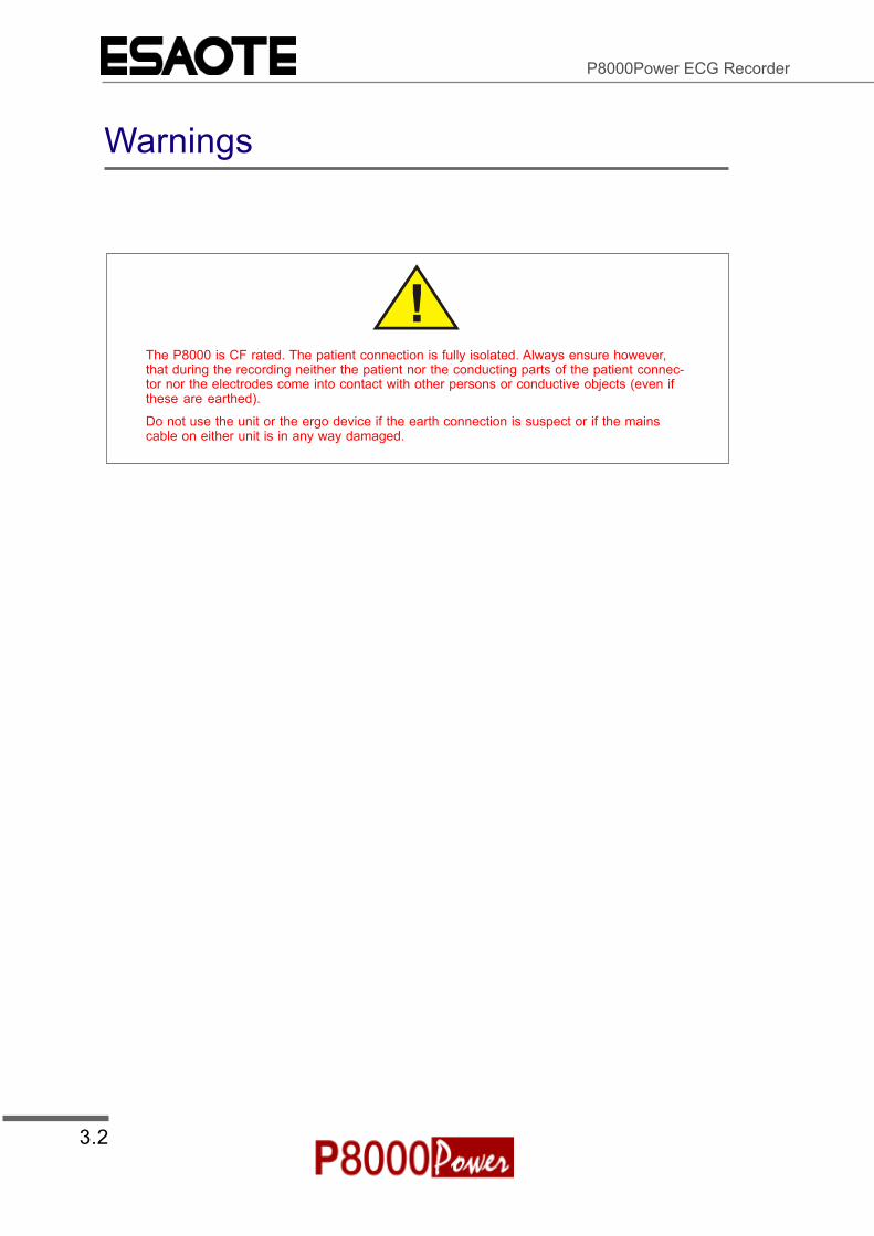
Warnings
The P8000 is CF rated. The patient connection is fully isolated. Always ensure however,that during the recording neither the patient nor the conducting parts of the patient connec-tor nor the electrodes come into contact with other persons or conductive objects (even ifthese are earthed).
Do not use the unit or the ergo device if the earth connection is suspect or if the mainscable on either unit is in any way damaged.

3.3Article Number 9740440033ESAOTE SPA 2002
Section 3Exercise ECGUser Guide
Exercise ECG with the P8000
The P8000 has an interface (RS-232) for control of digital treadmills and bicycles and has the followingfeatures:
Two treadmill protocols (one pre-programmmed and one user defined).
Three bicycle protocols (two pre-programmmed and one user defined).
Manual advancement to the next stage of the test at any time
Manual Hold of current stage at any time.
Automatic display of BP screen for entry of blood pressure measurements.
ST measurement point user defined
Stage printout at the end of every stage of the test or every two minutes giving:
° Test Stage
° Load applied (bicycle protocols
° Speed and elevation (treadmill protocols
° Patient data
° Blood pressure
° ECG segment of all leads
° ST slope and elevation of all leads
Continuous real-time printout at user request
Printout of previous 10 seconds at user request
Final report gives essential data in easily understandable graphical and tabular formats andgives a tabular overview of stage duration, load / speed-elevation, BP, heart rate and providesspace for physician`s comment, and break reasons.
3.4
P8000Power ECG Recorder
Running a Test - Flow Diagram OverviewInitial Preparation

3.5Article Number 9740440033ESAOTE SPA 2002
Section 3Exercise ECGUser Guide
Running a Test - Flow Diagram OverviewDefine Ergo Device and Select Protocol

3.6
P8000Power ECG Recorder
Running a Test - Flow Diagram OverviewTake a Resting ECG and Start Exercise Test

3.7Article Number 9740440033ESAOTE SPA 2002
Section 3Exercise ECGUser Guide
Running a Test - Flow Diagram OverviewEnter Recovery Stage and End Test

3.8
P8000Power ECG Recorder
Exercise Electrode Placement
A minimal resistance between skin and electrode is required to obtain the best ECG signal and ensurethe highest quality ECG recording. Therefore please note the following points:
Ensure that the patient is warm and relaxed.
Shave electrode area before cleaning.
Thoroughly clean the area with alcohol.
When applying the electrodes, ensure that a layer of gel is between the electrode and the skin.
Place the C4 electrode first - in the 5th intercostal space (ICS) so that it lines up approximatelywith the middle of the clavicle.
Then place:
° C1 in the 4th ICS parasternal right
° C2 in the 4th ICS parasternal left
° C3 between, and equidistant to, C4 and C2
° C6 on the patient`s side and aligned with C4
° C5 between, and equidistant to, C4 and C6
Note: When making an ECG with a child it is sometimes physically difficult to place all electrodes.When this is the case electrode V4 can be placed on the right side of the chest.
WARNING
During the ECG recording, ensure that neither the patient nor the leadingparts of the patient connection nor the electrodes (including the neutralelectrodes) come in contact with other persons or conductive objects,even when these are earthed.

3.9Article Number 9740440033ESAOTE SPA 2002
Section 3Exercise ECGUser Guide
Exercise Electrode Placement
Exercise ECG
Note: The colours shown here are according to Code 1 (European) requirements. The equivalent code2 colours are given on Page 2.6
3.10
P8000Power ECG Recorder
Running the Test
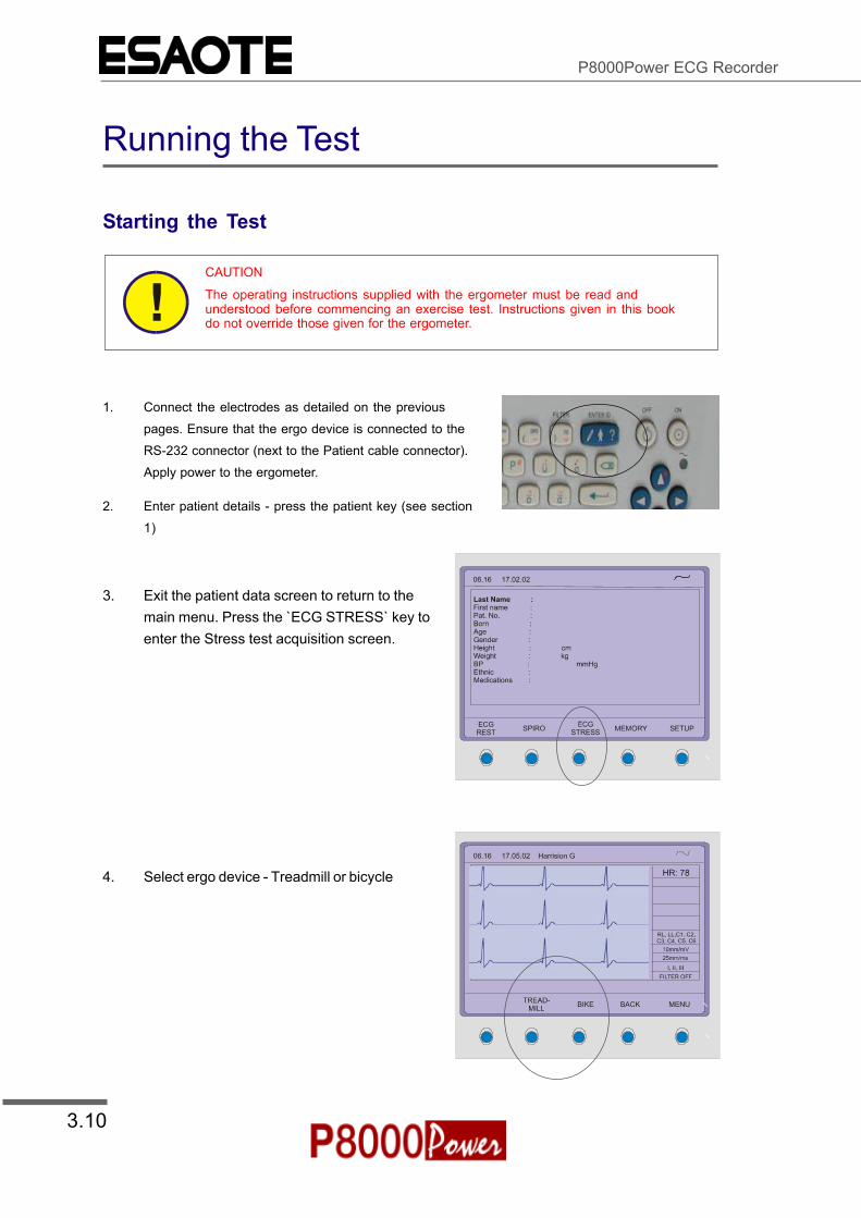
Starting the Test
CAUTION
The operating instructions supplied with the ergometer must be read andunderstood before commencing an exercise test. Instructions given in this bookdo not override those given for the ergometer.
1. Connect the electrodes as detailed on the previouspages. Ensure that the ergo device is connected to theRS-232 connector (next to the Patient cable connector).Apply power to the ergometer.
2. Enter patient details - press the patient key (see section1)
3. Exit the patient data screen to return to themain menu. Press the `ECG STRESS` key toenter the Stress test acquisition screen.
4. Select ergo device - Treadmill or bicycle

3.11Article Number 9740440033ESAOTE SPA 2002
Section 3Exercise ECGUser Guide
Running the Test
5. Select Protocol
WARNING
Check the resting ECG of the patient before carrying out an exercise test
6. Check the resting ECG for signal quality and carry out a resting ECG.
7. Warn the patient that the test is to beginand start the test in one of the followingways:
Press the `RUN TEST` softkey
or
Press the start test key

3.12
P8000Power ECG Recorder
Running the Test
When a treadmill protocol has been selected the treadmill starts at the speed defined (see ergosettings in Section 4).
When a bicycle protocol has been selected the load defined in the warm-up protocol is applied to thebicycle. The Stage indicator changes to `pre-exercise` and a time-bar is displayed with the durationsince the stage began
8. The first stage of the test startsautomatically at the end of thewarm-up period. If the warm-uptime is undefined, or you wish tostart the test before the end of thewarm-up period, press `NEXTSTAGE`.
The test starts and continuesaccording to the protocol defined.
9. The test is stopped and the recovery stage entered in one of thefollowing ways:
Press the `RECOVERY` softkey
or
Press the STOP key
EMERGENCY STOP
To stop the test and treadmill at any time, press the STOP key twice

3.13Article Number 9740440033ESAOTE SPA 2002
Section 3Exercise ECGUser Guide
During The Test
Change lead group Change Speed
Change Sensitivity Filter On/Off
Changing the Display Lead Group on the screen and ManualPrintoutPress on the left / right arrow keys (Key 1 and 2 resp.) to toggle through the leads.
Note: The lead order is defined in the system settings ( - see Section 2 for details)
Changing the Display Sensitivity and Speed on the screenand Manual PrintoutPress the sensitivity keys (keys 3 to 6) and speed keys (keys 7 to 9) to set for the display and printout
Switching the Filter on / offPress the filter key to toggle the Myogram muscle filter on / off

3.14
P8000Power ECG Recorder
During The Test
Advancing to the next Stage in the Protocol/ Holding theCurrent StageAt any time during the test, manual advancement to the next stage of the protocol can be initiatedmanually. Also, the duration of any stage of exercise can be extended beyond the preprogrammedduration. This is carried out with the HOLD and NEXT STAGE softkey options. The current stage and theduration of the stage is displayed in the exercise information box.
ST Elevation and SlopeThe real-time ST measurement elevation and slope is displayed for the programmed lead. Themeasurement interval (after the J-point) and the selected lead, can be user defined and are described insystem settings - Section 4

3.15Article Number 9740440033ESAOTE SPA 2002
Section 3Exercise ECGUser Guide
During The Test
Obtaining Extra Printout(s) During the TestStage printouts are given one minute before the end of every stage, or every two minutes if any stage inthe protocol is greater than two minutes.
To obtain a continuous printout at any stage in the test:
press the `MANUAL PRINT` keyA continuous printout is given until stopped. The lead group, sensitivity and speed is set via thekeyboard (see previous page).
To stop the printout:
press the STOP button on the keyboard orclick on the `STOP` softkey
To obtain a printout previous 10 seconds of therecording
Press the `10' SEC` soft keyorPress the START key
.
3.16
P8000Power ECG Recorder
During the Test
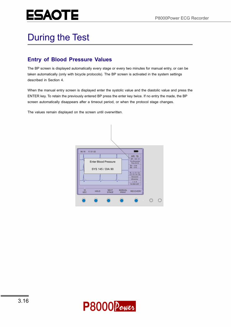
Entry of Blood Pressure ValuesThe BP screen is displayed automatically every stage or every two minutes for manual entry, or can betaken automatically (only with bicycle protocols). The BP screen is activated in the system settingsdescribed in Section 4.
When the manual entry screen is displayed enter the systolic value and the diastolic value and press theENTER key. To retain the previously entered BP press the enter key twice. If no entry the made, the BPscreen automatically disappears after a timeout period, or when the protocol stage changes.
The values remain displayed on the screen until overwritten.
Enter Blood Pressure
SYS 145 / DIA 90

4.1
Section 4Setup
Article Number 9740440033
ESAOTE SPA 2002
User Guide
Section 4
Setup
This section contains all the system settings and measurement settings
available for the P8000Power. All settings made are remembered by the unit
(even when the unit is switched off). Many of the settings are `defaults`. This
means that when the unit is switched on or a new patient is defined, the
default values are set. Many settings can however, be changed for specific
patients during a recording.

4.2
P8000Power ECG Recorder
Navigating in the Setup Screens
In setup screens where there is multi choice, navigation to the next screen and selection of specific
settings, is the same for all. This is as follows:
Use the ENTER key to select a (highlighted) setting and
confirm.
(or use softkey function SELECT)
Use the left/right arrow keys
to confirm settings and go
to the previous/next setup
screen.
(or use softkey function
NEXT)
Use the up/down arrow keys to confirm
settings and go to the previous/next setting
in the current screen.
(or use softkey functions up/down)

4.3
Section 4Setup
Article Number 9740440033
ESAOTE SPA 2002
User Guide
ECG Settings
The P8000Power ECG and system settings are entered by selecting 'setup' from the initial screen:
NOTE:
As a safety feature to prevent accidental change, in some software versions`SETUP` is not displayed until the Function key (Fn) has been pressed.
The following pages detail the programmable ECG parameters.
NOTE:
In units where the interpretation option is not installed, the measurements,markings, interpretation, and average settings are not displayed.

4.4
P8000Power ECG Recorder
ECG Settings
! Use the select softkey to select the different settings
! Use the Up/Down softkeys to highlight the various options.
Auto Mode Format 1 and 2
Two separate Auto formats can be defined for the P8000Power. Use the NEXT softkey to enter the Auto
Format 2 settings. AUTO
Note to confirm setting and to move onto the next screen (Format 2).
ECG Printout
Press the `SELECT` softkey to choose from the following options:
No Printout No printout of the ECG given at the end of an auto mode recording (the recording
can be stored in the memory and printed at a later time if required).
4*3 + 1 Rhythm Leads are printed in a 4 * 3 format at 25mm/s, with the selected rhythm lead at the
bottom of the page at 25mm/s.
1*12 at 25mm/s Leads are printed in a 1 * 12 format at 25mm/s - no rhythm lead printed.

4.5
Section 4Setup
Article Number 9740440033
ESAOTE SPA 2002
User Guide
ECG Settings
8*5s + 4*10s The first 8 leads printed for 5 seconds and the last 4 leads printed for 10 seconds.
Short at 25mm/s Leads are printed in short form (1 sheet) at 25mm/s.
Long at 25mm/s Leads are printed in long form (2 sheets) at 25mm/s.
Long at 50mm/s Leads are printed in long form (2 sheets) at 50mm/s.
Average Cycles
No Printout No printout of average cycles
4*3, 25mm/s + 2 Rhythm Leads are averaged over the entire 10 second recording and printed in 4
groups of 3 leads at 25mm/s, with the two selected rhythm leads at the bottom of
the page at 25mm/s.
4*3, 50mm/s + 2 Rhythm Leads are averaged over the entire 10 second recording and printed in 4
groups of 3 at 50mm/s, with the two selected rhythm leads at the bottom of the
page at 25mm/s.
2*6, 50mm/s + 2 Rhythm Leads are averaged over the entire 10 second recording and printed in two
groups of six at 50mm/s, with the two selected rhythm leads at the bottom of the
page at 25mm/s.
Rhythm Leads
Select the rhythm lead 1 and rhythm lead 2 as described above.
Rhythm Lead 1 Select any lead (I, II, III, aVR, aVl, aVF, V1 to V6)
Rhythm Lead 2 Select any lead (I, II, III, aVR, aVl, aVF, V1 to V6)
Measurements, Markings and Interpretation
Measurements Select yes or no to print a detailed table of measurement results
Markings Select yes or no to print reference markings on the ECG average cycle print. A
vertical marker shows the beginning and end of P wave and QRS, and the end of
the T wave
Interpretation Select yes or no to print interpretation statement
Note: The sensitivity of the interpretation and the printing/not printing of
abnormality statements can additionally be set for the interpretation.
These are described on the following pages.
Full details of the interpretation option are given in the ECG Measurement and Interpretation booklet(Art. No. 9740440088).

4.6
P8000Power ECG Recorder
ECG Settings
Filters
There are five different filters which can be set individually as follows:
Baseline filter
The cutoff frequency of the filter is set on the top line. The cutoff can be 0.05 Hz, 0.15 Hz or 0.30 Hz.
Note:
The set value is the lower limit of the frequency range and is normally set to 0.05Hz. The settings 0.15 and 0.30 Hz should only be used when absolutely neces-sary, as the possibility exists that they could affect the original ECG signal,especially the ST segments.

4.7
Section 4Setup
Article Number 9740440033
ESAOTE SPA 2002
User Guide
ECG Settings
Myogram filter
The Myogram filter suppresses disturbances caused by strong muscle tremor. The filter is applied by
pressing the FILTER key (or programmed on as default when
the unit is switched on).
When the Myogram filter is on, `FILTER ON` is displayed in the
information box.
The cutoff frequency is user defined at 25Hz or 35Hz. When `off
at power up` is selected, the Myogram filter is off when the unit
is first switched on.
Note: An ECG recorded in auto mode is stored unfiltered. It is therefore possible to print the stored
ECG either with or without passing the myogram filter. Filter ON is indicated on the LCD.
Mains filter
The mains filter is an adaptive digital interference filter designed to suppress ac interference without
attenuating or distorting the ECG.
Set the mains filter in accordance with the frequency of your local mains supply.
Baseline Stabiliser (SBS)
The baseline stabiliser greatly reduces the baseline fluctuations without affecting the ECG signal. The
purpose of the stabiliser is to keep the ECG signals on the baseline of the printout. This filter is only
effective in auto mode printout.The Baseline Stabiliser is applied to a recording (on), or not applied to a
recording (off).
Smoothing Filter (SSF)
The smoothing filter (SSF: smoothing filter) is a low pass filter to suppress high frequency artefacts
between the QRS complexes. When this filter is switched on, `SSF` is shown on the bottom line of the
automatic printout.
4.8
P8000Power ECG Recorder
ECG Settings
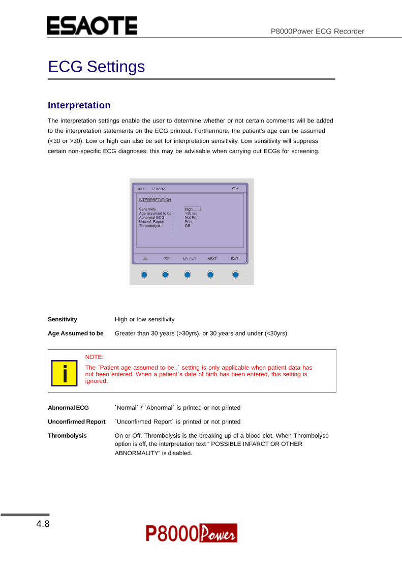
Interpretation
The interpretation settings enable the user to determine whether or not certain comments will be added
to the interpretation statements on the ECG printout. Furthermore, the patient’s age can be assumed
(<30 or >30). Low or high can also be set for interpretation sensitivity. Low sensitivity will suppress
certain non-specific ECG diagnoses; this may be advisable when carrying out ECGs for screening.
Sensitivity High or low sensitivity
Age Assumed to be Greater than 30 years (>30yrs), or 30 years and under (<30yrs)
NOTE:
The `Patient age assumed to be..` setting is only applicable when patient data hasnot been entered. When a patient`s date of birth has been entered, this setting isignored.
Abnormal ECG `Normal` / `Abnormal` is printed or not printed
Unconfirmed Report `Unconfirmed Report` is printed or not printed
Thrombolysis On or Off. Thrombolysis is the breaking up of a blood clot. When Thrombolyseoption is off, the interpretation text “ POSSIBLE INFARCT OR OTHERABNORMALITY” is disabled.

4.9
Section 4Setup
Article Number 9740440033
ESAOTE SPA 2002
User Guide
ECG Settings
Leads
Defining Lead Sequence & PrintoutThe required settings can be selected as follows:
Lead Sequence Select between Standard lead sequence or Cabrera
Lead groupings are shown on page 2.10
Signals Select between:
Simultaneous - All ECG leads are printed in the same time segment (in automatic
mode only), or
Sequential - Each group is a contiguous time segment of approximately 2.5 or 5
seconds (in automatic mode only).
Auto-Centering Select between
On - All ECG traces are centred dynamically for optimal use of paper width, or
Off - ECG traces are set to a fixed baseline position and may possibly overlap.

4.10
P8000Power ECG Recorder
ECG Settings
The lead group settings allow extra leads to be displayed on the screen when set to `on`. The following
lead groups can be displayed:
Rhythm Lead Group II, avF, III / V2, V4, V5
Left Posterior (V4-V9) V4, V5, V6 / V7, V8, V9
Right Precordials (V5r) V1, V2, V3 / V3r, V4r, V5r
Right Precordials (V6r) V1, V2, V3r / V4r, V5r, V6r
Nehb (D, A, J) D, A, J (only three leads)
The above leads can also be printed when displayed (only in manual mode)
The lead groups are changed both on the screen and on the manual printout with the lead next/previous
keys:
Auto Storage
Set the auto storage setting to 'on' or 'off'. When 'on' is set, recordings are automically saved when an
ECG is completed. When 'off' is selected, the user is prompted to save an ECG recording when
completed.

4.11
Section 4Setup
Article Number 9740440033
ESAOTE SPA 2002
User Guide
Stress Settings
The P8000Power Stress ECG settings are entered by selecting 'Setup' and 'Stress Settings' from the
initial screen:
The following pages detail the stress settings for the P8000Power.
4.12
P8000Power ECG Recorder
Stress Settings
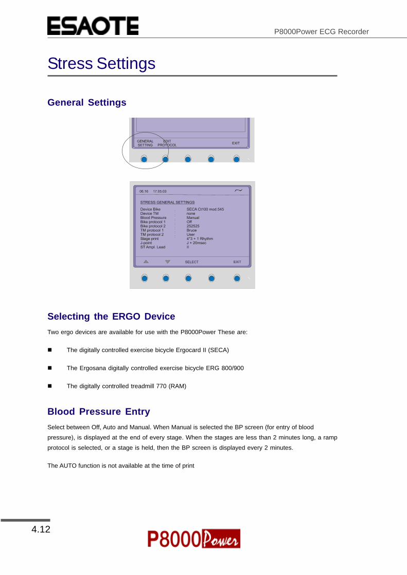
General Settings
Selecting the ERGO Device
Two ergo devices are available for use with the P8000Power These are:
! The digitally controlled exercise bicycle Ergocard II (SECA)
! The Ergosana digitally controlled exercise bicycle ERG 800/900
! The digitally controlled treadmill 770 (RAM)
Blood Pressure Entry
Select between Off, Auto and Manual. When Manual is selected the BP screen (for entry of blood
pressure), is displayed at the end of every stage. When the stages are less than 2 minutes long, a ramp
protocol is selected, or a stage is held, then the BP screen is displayed every 2 minutes.
The AUTO function is not available at the time of print

4.13
Section 4Setup
Article Number 9740440033
ESAOTE SPA 2002
User Guide
Stress Settings
Selecting the Default Test Protocol
This setting defines the two bike, and the two treadmill protocols that are available for selection when
commencing a stress test.
Three bike protocols (two factory defined and one user defined), and two treadmill protocols (one factory
and one user defined) are available for selection.
The factory set protocols, and details of setting the user defined protocols, are given on the following
page.
Defining the Stage Printout Format
A stage printout is given one minute before the end of every stage. When the stages are less than 2
minutes long, a ramp protocol is selected, or a stage is held, then a prinout is given every 2 minutes.
The waveforms are averaged to give 4 x 3 plus 1 rhythm lead, or 6 x 2. The rhythm lead printed is the
lead defined for automatic format 1(resting).
ST Amplitude Lead
Define the lead that is used for ST measurement. This lead is also printed as the rhythm lead if set in
the stage printout.
4.14
P8000Power ECG Recorder
Stress Settings
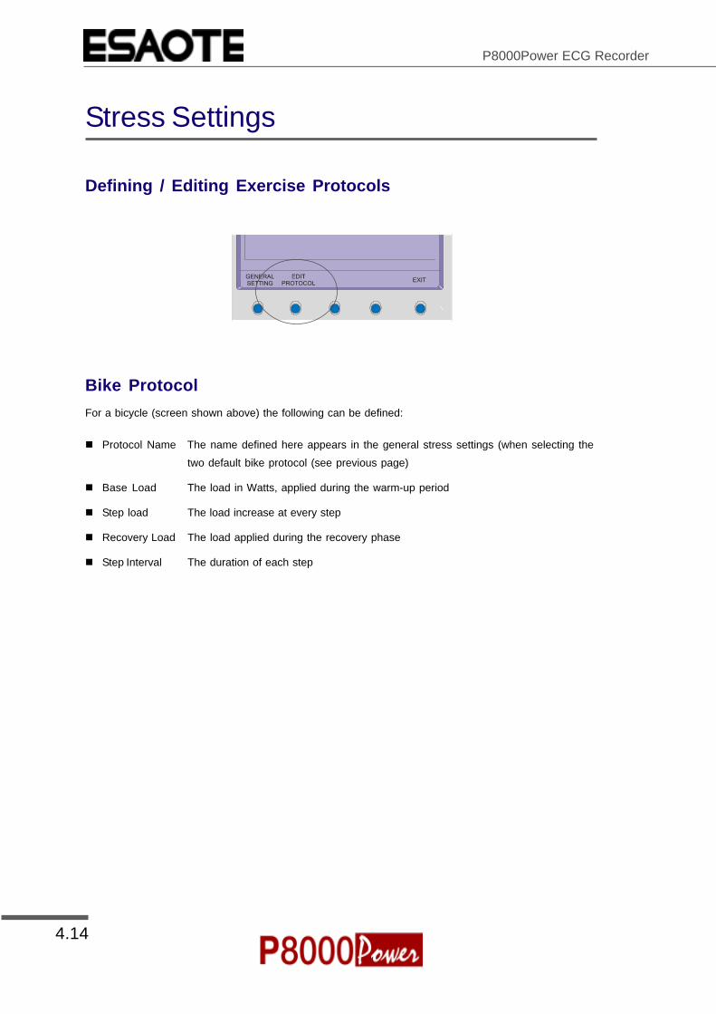
Defining / Editing Exercise Protocols
Bike Protocol
For a bicycle (screen shown above) the following can be defined:
! Protocol Name The name defined here appears in the general stress settings (when selecting the
two default bike protocol (see previous page)
! Base Load The load in Watts, applied during the warm-up period
! Step load The load increase at every step
! Recovery Load The load applied during the recovery phase
! Step Interval The duration of each step

4.15
Section 4Setup
Article Number 9740440033
ESAOTE SPA 2002
User Guide
Stress Settings
Factory Programmed Bicycle Protocols
Two factory programmed Bicycle protocols are available 252525, and 502525. These give a base load
(warmup) of 25W (50W), with a step load for both protocols of 25W and a recovery load of 25W.
Treadmill Protocol
For a treadmill Protocol, the following can be set:
! Protocol Name As for a bike protocol
! Step Interval The duration of each step
! Speed The individual treadmill speed of each step
! Elevation The individual treadmill elevation of each step
Factory programmed Treadmill Protocol
One factory programmed Treadmill protocols is available as follows:
Bruce
Stage Duration Speed Elevation
(min) km/h (mph) %
1 3 2.7(1.7) 10%
2 3 4.0 (2.5) 12%
3 3 5.4 (3.4) 14%
4 3 6.7 (4.2) 16%
5 3 8.0 (5.0) 18%
6 3 8.8 (5.5) 20%
7 3 9.6 (6.0) 22%

4.16
P8000Power ECG Recorder
System Settings
The P8000Power system settings are entered by selecting 'setup' and 'system settings' from the initial
screen:
The following pages detail system settings for the P8000Power.

4.17
Section 4Setup
Article Number 9740440033
ESAOTE SPA 2002
User Guide
System Settings
Unit
User Identification (User ID)
The user identification is printed on all recordings. The user ID can be the department, doctor or
hospital etc. Select User ID and a blinking cursor is present - enter up to 30 characters via the keypad.
Note: If the unit is reset to the default settings (see following), the user identification must be re-
entered.
Date and Time
Enter the date in the format day.month.year. Enter the time using
the standard 24 hr notation. When set, the ENTER key must be
pressed to confirm.

4.18
P8000Power ECG Recorder
System Settings
Language
Several languages are already programmed into the unit. Select the language for the screen display and
for the printout. The language will also set the units used by the system.
The difference between American and English is as follows:
American Standard English
measurements in inches measurements in centimetres
temperature in Fahrenheit temperature in degrees centigrade.
Mains filter setting - 60Hz mains filter setting - 50Hz
date order mm-dd-yy date order dd-mm-yy
Additionally, when American is set, further race settings are given and Spiro diagnosis is based on ITS
recommendations - see Spirometry handbook.
The default language is Standard English.
Startup Screen
Here you can specify the first screen to be displayed when the unti is switched on. Select between
patient data screen (for entry of new patient) or data acquisition screen (ECG).
Paper Mode
The internal printer can print on A4 or letter size paper. Set according to the paper used.

4.19
Section 4Setup
Article Number 9740440033
ESAOTE SPA 2002
User Guide
System Settings
Communication
Baudrate Select a Baud rate between 115200 and 9600 Baud, according to the modem/
computer used. Most computers can connect at 115200 Baud and the standard
modem speed is 57600 Baud. If problems are experienced during transmission
reduce the Baud rate.
Mode Select between line (computer connected directly to the RS-232 interface), or
modem (for transmission over the phone network)
Phone No. Enter the telephone number preceded by `T` or `P` (tone or pulse).
A comma `,` gives a one second pause in dialling - this may be necessary for
example, if an outside line is required.
Modem Init. Enter the modem initialisation codes. Full details will be found in the user guide for
your modem. However, the modem initialisation must contain at the minimum, the
following commands with the prefix `AT`.
`Q0`- modem sends response
`V0`- numerical response codes
`E0`- no command echo
The standard modem initialisation code is: ATB0L1V0Q0E0S0=0
If in doubt about any of these settings, please contact your phone company and/or modem supplier.
4.20
P8000Power ECG Recorder
System Settings
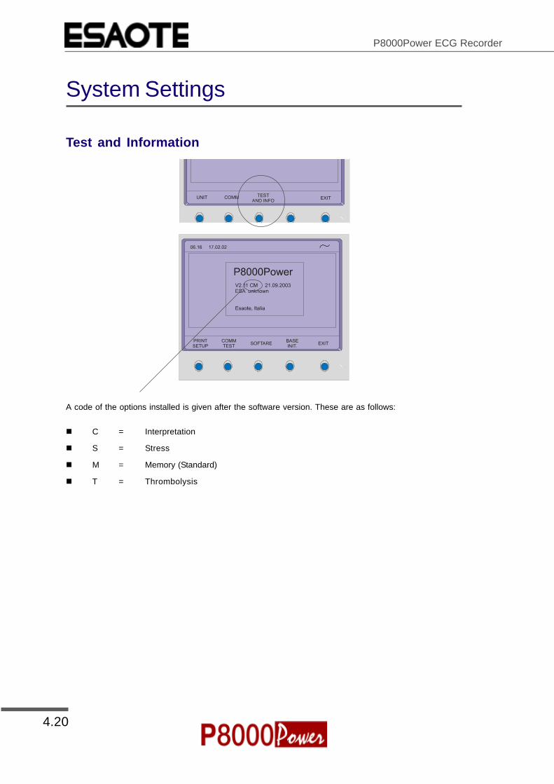
Test and Information
A code of the options installed is given after the software version. These are as follows:
! C = Interpretation
! S = Stress
! M = Memory (Standard)
! T = Thrombolysis

4.21
Section 4Setup
Article Number 9740440033
ESAOTE SPA 2002
User Guide
System Settings
Obtaining a printout of all current settings
To obtain a printout press the `PRINT SETUP` softkey
A printout of the defined settings will be produced and gives the following information, depending on the
installed software:
Unit designation Software version, Software options installed (C = Interpretation, M =
Memory (standard), S = Stress) and Serial number of the unit
ECG Format (1 and 2) Speed Default speed setting
Auto printout Long (ooo), Short (o) or Suppressed (-)
MECG Average cycles as defined in auto ECG recording
setup (e.g. 4 * 3 (25 mm/s) + 2)
Rhythm leads Leads selected for R1, R2 resp.
Measurements Print - Enabled (+) or Suppressed (-)
Marks Print - Enabled (+) or Suppressed (-)
Interpretation Print - Enabled (+) or Suppressed (-)
Leads Sequence Standard (S) or Cabrera (C)
Signals Printout of signals - Sequential or Simultaneous
Auto Centering Enabled (+) or Suppressed (-)
Lead Group Rhythm, V9, V4r, V6r, DAJ, ON (+) or OFF (-) for
each lead group

4.22
P8000Power ECG Recorder
System Settings
Filter Baseline Filter 0.05, 0.15 or 0.30 Hz
Mains Filter 50, 60 Hz or OFF (-)
Myogram Filter 25 or 35 Hz, ON (+) or OFF (-)
SSB Filter Smoothing Filter Enabled (+) or Suppressed (-)
SSF Filter Baseline Stabiliser Enabled (+) or Suppressed (-)
Interpretation Sensitivity Low (-) or high (+) sensitivity
A30 Patient age is assumed to be < 30 (-) or >30 (+)
U ‘Unconfirmed report’ is written (+) or suppressed
(-)
Abnormal Normal / Abnormal printed Enabled (+) or
Suppressed (-)
General Auto Storage On(+), or Off (-)
Comm Baud rate 115200, 57600, 38400, 28800, 14400 or 9600.
This is followed by parity setting (Y/N), bits and
number of stop bits.
Mode Line or Modem
Spiro F=f(v) Enabled (+) or Suppressed (-)
Flow =f(V) Enabled (+) or Suppressed (-)
Diagn. Enabled (+) or Suppressed (-)
PEFD (l/min) Enabled (+) or Suppressed (-)
Axis 5, 10 or 20 mm/s
Stress Bike 900 / 911 or SECA CT100 or none
Prot 252525 or user defined
TM ETM435/TM4000ES or RAM 770CE or MTM-1500
or none
Prot Bruce or user defined
BP Manual, automatic of none
Stage Print leads and format
ST Lead Defined lead for ST Measurement
J- Point J plus 20, 40, 60, or 80 milliseconds
Date and Time System date and time
User ID User indentification (if set)
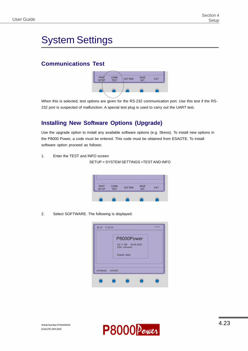
4.23
Section 4Setup
Article Number 9740440033
ESAOTE SPA 2002
User Guide
System Settings
Communications Test
When this is selected, test options are given for the RS-232 communication port. Use this test if the RS-
232 port is suspected of malfunction. A special test plug is used to carry out the UART test.
Installing New Software Options (Upgrade)
Use the upgrade option to install any available software options (e.g. Stress). To install new options in
the P8000 Power, a code must be entered. This code must be obtained from ESAOTE. To install
software option proceed as follows:
1. Enter the TEST and INFO screen
SETUP > SYSTEM SETTINGS >TEST AND INFO
2. Select SOFTWARE. The following is displayed:

4.24
P8000Power ECG Recorder
System Settings
3. Select UPGRADE. The following is displayed:
4. Enter the upgrade code
When the correct code is entered, acceptance of the code is indicated by a series of beeps. The
option can be used immediately.
CAUTION
More than 10 attempts to enter the incorrect code blocks the unit
Updating the Software
Use the Update option to update the current software.
Details to update the software is given in Section 5 of the P8000 Power Service handbook.

4.25
Section 4Setup
Article Number 9740440033
ESAOTE SPA 2002
User Guide
System Settings
Default Settings
To reset the unit to the base default settings, press the `BASE INIT` softkey. As the unit resets to the
default values a message is briefly displayed on the LCD. The base settings (Defaults) are given on the
following page.

4.26
P8000Power ECG Recorder
System Settings
Unit Defaults Table
Settings Standard With Interpretation
Language As set As set
Auto Format 1 ECG: 25mm/s, short (o) ECG : 25mm/s, short (o)
Rhythm Leads V1 Rhythm Leads V1, II
MECG: 2*6 (50mm/s + 1)
Measurements: Suppressed (-)
Interpretation: Enabled (+)
Marks: Enabled (+)
Auto Format 2 ECG: 25mm/s, Long (ooo) ECG : 25mm/s, long (ooo)
Rhythm Leads V1 Rhythm Leads V1, II
MECG: none
Measurements: Suppressed (-)
Interpretation: Suppressed (-)
Marks: Enabled (+)
Leads Sequence Standard (S) Sequence Standard (S)
Rhythm On (+) Rhythm On (+)
V9 On (+) V9 On (+)
V4r Off (-) V4r Off (-)
V5r Off (-) V5r Off (-)
DAJ Off (-) DAJ Off (-)
Autom. Centering Enabled (+) Autom. Centering Enabled (+)
Signals Sequential Signals Sequential
Filter Baseline 0.05Hz Baseline 0.05Hz
Mains Filter 50Hz (60Hz) Mains Filter 50Hz (60Hz)
Myogram 35Hz, OFF Myogram 35Hz, OFF
Memory and Communication Baud rate 57600 bps Baud rate 57600 bps
Trans. mode: line Trans. mode: line
Interpretation Settings Suppressed (-)
U: Enabled (+)
A30: Under thirty (-)
Auto-Storage Off Off

4.27
Section 4Setup
Article Number 9740440033
ESAOTE SPA 2002
User Guide
System Settings
Settings Standard With Interpretation
Spiro FVC=f(t) on(+) FVC=f(t) on(+)
F=f(v) on(+) F=f(v) on(+)
Diagn.on(+) Diagn.on(+)
PEF (l/min)on(+) PEF (l/min)on(+)
Axis 10 mm/s Axis 10 mm/s
Stress Bike 900 / 911 Bike 900 / 911
Prot 252525 / User Defined Prot 252525 / User Defined
TM ETM435/TM4000ES TM ETM435/TM4000ES
Prot Bruce / User Defined Prot Bruce / User Defined
BP off BP off
Stage Print 4*3 + 1 Rhythm Stage Print 4*3 + 1 Rhythm
ST Lead V5 ST Lead V5
J- Point J + 60msec J- Point J + 60msec

4.28
P8000Power ECG Recorder

5.1
Section 5Maintenance, Fault-Finding and Technical Data
Article Number 9740440033ESAOTE SPA 2002
User Guide
Section 5
Maintenance, Fault-Findingand Technical Data
This section contains the routine maintenance procedures and the tests and checksthat can be carried out by the user; a short fault-finding section is also included. Thetechnical data at the end of the book is subject to change.

5.2
P8000Power ECG Recorder
Care & Maintenance
Self-testEvery time the unit is switched on a built-in test program is initiated. If an error is detected, the unit willnot switch on and a table may be displayed giving information for the service staff. Details of the testprogram is given in the P8000Power Service Handbook.
To obtain a printout of an error message press `P` when the table is displayed. Exit an error screen bypressing the ENTER key on the keypad.
Communication (RS-232) TestA built-in program to check the transmission connector. This test is entered from the `setup` menu:
SETUP > SYSTEM SETTINGS > TEST AND INFO > COMM TEST
This test uses a special test plug (not supplied) which shorts the incoming/outgoing connectors tocheck transmission line and connector to ensure that the P8000Power transmission circuits arefunctioning. Details of this test are given in the P8000Power Service Handbook.
12 Monthly CheckIt is stipulated that a technical safety check must be performed at least every 24 months. It is stronglyrecommended however, that the unit undergoes a technical safety check every 12 months. This safetycheck shall include the following:
Visual inspection of the unit and cables.
Electrical safety tests according to EN 60601-1 (1990) Clause 19
Functional tests according to the Service Handbook.
The test results must be documented.

5.3
Section 5Maintenance, Fault-Finding and Technical Data
Article Number 9740440033ESAOTE SPA 2002
User Guide
Care & Maintenance
Cleaning the Casing
WARNING
Switch the unit off before cleaning and disconnect the mains. Do not, underany circumstances, immerse the apparatus into a cleaning liquid or sterilisewith hot water, steam, or air.
The casing of the P8000Power can be cleaned with a soft damp cloth on the surface only. Wherenecessary a domestic non-caustic cleaner can be used for grease and finger marks.
Cleaning the Patient CableThe patient cable must not be exposed to excessive mechanical stress. Whenever disconnecting theleads, hold the plugs and not the cables. Store the leads in such a way as to prevent anyone stumblingover them or any damage being caused by the wheels of instrument trolleys.
The cable can be wiped with soapy water. Sterilization, if required, should be done with gas only and notwith steam. To disinfect, wipe the cable with hospital standard disinfectant.
Cleaning the Thermal Print HeadIf the printer is used a lot, a residue of printers ink ( from the grid on the paper) can build up on the printhead. This can cause the print quality to deteriorate. We recommend therefore that every month the printhead is cleaned with alcohol as follows:
Extend the paper tray and remove paper. The thermal printhead is found under the paper tray.
With a tissue dampened in alcohol, gently rub the printhead to remove the ink residue. If the printhead isbadly soiled, the colour of the paper grid ink (i.e. red or green) will show on the tissue.

5.4
P8000Power ECG Recorder
Replacing the Recording Paper
The recording papermust be replaced assoon as the end of thepaper is indicated by ared stripe on the loweredge. After the indicationfirst appears, there areabout 8 pages left.However, we recommendthat the paper bereplaced immediately. Ifno paper is left, theprinting process isinterrupted and a warning is given onthe screen. To replace the paperproceed as follows:
Press the paper tray eject key.
Remove any remaining paperfrom the paper tray.
Place a new paper pack intothe paper tray with the printed(grid) side facing upwards andthe black papermark to the topof the unit.
Place thebeginning of thepaper over theblack paperroller on thepaper tray cover.

5.5
Section 5Maintenance, Fault-Finding and Technical Data
Article Number 9740440033ESAOTE SPA 2002
User Guide
Replacing the Recording Paper
Press the paper trayeject key to return thepaper tray in position.
Press the STOP keyto transport the paperto the start position.
ESAOTE can onlyguarantee perfectprintouts whenESAOTE originalchart paper or chartpaper of the samequality is used.
Thermal Paper HandlingThe thermal paper used in the P8000Power requires slightly different handling to normal paper as it canreact with chemicals and to heat. However, when the following points are remembered, the paper willgive reliable results:
The following points apply to both storage, and when archiving the results.
1. Before use, keep the paper in its original cardboard cover. Do not remove the cardboard coveruntil the paper is to be used.
2. Store in a cool, dark and dry area.
3. Do not store near chemicals e.g. sterilisation liquids.
4. In particular do not store in a plastic cover.
5. Certain glues can react with the paper - do not attach the printout onto a mounting sheet withglue.

5.6
P8000Power ECG Recorder
Fault-Finding
Unit does not switch on, Blank Screen
Green mains indicator on?
No? Check mains supply.
Yes? Check contrast. Press the function key (FN) and then the UP/DOWN cursorskeys to change the contrast.
If mains is OK and the screen is still not lit:
Press the master reset on the back of the unit.
Press the OFF key.
Wait a few seconds and switch on again.
If the screen is still not lit: Call your local ESAOTE representative.
QRS traces overlap
Change sensitivity setting
Ensure that the automatic sensitivity reduction is not switched off.
Reset signals to baseline - press the 1mV key
Check electrode contact - Replace electrodes
If traces still overlap: Call your local ESAOTE representative.
Note: Some patients have very high amplitudes and even on the lowest sensitivitysettings, the QRS traces can overlap.
‘Noisy’ traces
Check electrode contact
Reapply electrodes
Ensure that the patient is relaxed and warm
Check all filter settings.
Activate Myogram filter - change cutoff frequency
Ensure mains filter is correct for mains supply
If the trace is still `noisy`: Call your local ESAOTE representative.

5.7
Section 5Maintenance, Fault-Finding and Technical Data
Article Number 9740440033ESAOTE SPA 2002
User Guide
Fault-Finding
No printout obtained after an auto mode recording
Ensure that paper is loaded.
Check Settings - ensure that at least one item is selected for print after an autoECG is recorded
If the printer still doesn`t work: Call your local ESAOTE representative.
Printout fades or is not clear
Ensure that fresh ESAOTE paper is installed.
Note that the thermal paper used for the P8000Power is heat and light sensitive. Ifit is not stored in its original seal, stored in high temperatures or is simply old, printquality can deteriorate.
Ensure that the paper has been installed correctly with the paper mark at the top.
Over a period of time, the printing ink from the grid on the paper can form a film onthe thermal print head. Clean the thermal print head with a clean cloth asdescribed previously.
If the problem persists call your local ESAOTE representative.
No printout of interpretation statement or measurements
Check that the interpretation and measurement options are enabled for theprintout.
No key response, LCD locked
Switch off, and switch on again after a few seconds. If this is not possible, use anarrow blunt instrument (e.g. a straightened paper clip) to press the master resetswitch on the back panel.
If the unit is still not working call your local ESAOTE representative.

5.8
P8000Power ECG Recorder
Accessories and Disposables
Your local representative stocks all the disposables and accessories available for the P8000Power. Afull list of all ESAOTE representatives can be found on the ESAOTE website (www.esaote.com). In caseof difficulty contact our head office. Our staff will be pleased to help process your order or to provide anydetails for all ESAOTE products.

5.13
Section 5Maintenance, Fault-Finding and Technical Data
Article Number 9740440033
ESAOTE SPA 2002
User Guide
Technical Data
Standard
P8000Power ECG with 12 simultaneous leads, pacemaker detection, automatic ECG measurement.
Accessories: 1 10-lead patient cable
1 set of electrodes or disposable electrodes
1 power cable
1 pack chart paper
Operating manual
Software options: ARCHIMED data management PC software to save, validate and
archive ECG data on PC
Hardware options: Equipment trolley
Spirometry sensor SP-250 or SP-260
Calibration syringe
External printer
ConfigurationsThe P8000 Power is available in three versions:
Version M - Standard: Unit with ECG recording, measurements, memory and printout
capabilities.
Version C - Interpretation: Standard unit with ECG Interpretation program
Version T - Thrombolysis: C unit with Thrombolysis
Version S - Stress: C unit with ECG stress test program
Note The spirometry option, using the SP-250 sensor or SP-260 sensor, is available when the sensor
is connected to the RS-232 interface.
Technical data subject to change without notice.

5.10
P8000Power ECG Recorder
Technical Data
Safety Standards:Safety standard: CF according IEC 60601-1 and
IEC 601-2-25
Protection class: I according to IEC 60601-1 (with internal battery), IIa according to EECdirective 93/42 (medical protection class)
Conformity: CE according to 93/42/EEC
Technical Data for ECG:Patient input circuit: Fully floating and isolated, defibrillation-protected (only with original
ESAOTE patient cable)
Monitor display: 3-channel display of the selected leads
25, 50 mm/s
5, 10, 20 mm/mV
Filter status (on/off)
Insufficient electrode contact
Heart Frequency, HF
mm/mv, mm/s
Leads: 12 simultaneous leads: Standard / Cabrera
Chart print-out speed: 5/10/25/50 mm/s (manual print)
Sensitivities: 5/10/20 mm/m, either automatically adjusted or manually selected
Automatic lead programs: 6/12-channel presentations of 12 simultaneously recorded standardleads on one or more A4 pages
Numerous print-out formats can be selected
Data record: Patient data (name, age, height, weight, BP), user ID
Listing of all ECG recording conditions (date, time, filter)
With optional interpretation (C) program: ECG measurements results(intervals, amplitudes, electrical axes), average complexes withoptional measurement reference markings, guidance on interpretingadult and paediatric ECGs

5.11
Section 5Maintenance, Fault-Finding and Technical Data
Article Number 9740440033ESAOTE SPA 2002
User Guide
Technical Data
Recording track: 6/12-channel presentation, optimal positioning on a width of 200mm, automatic baseline adjustment
Filter: Myogram filter (muscle tremor filter): 25 Hz or 35 Hz, can be switchedon/off
ECG amplifier: Simultaneous recording of all 9 active electrode signals (= 12 leads)
Sampling frequency: 1000 Hz
Pacemaker detection: > + 2 mV/> 0.1 ms
Technical Data for Spirometry (Option):Measured values: FVC: FVC, FEV0.5, FEV1.0, FEV3.0, FEV0.5/FVC, FEV1,0/FVC, FEV3.0/FVC,
FEF0.2-1.2, FEF25-75%, FEF75-85%, PEF, FEF25%, FEF50%, FEF75%, FIVC, FIV1.0 ,FIV1.0/FIVC, FIV1.0/FVC, PIF, FIF50%, FMFT,
SVC: SVC, ERV, IRV, TV,
MVV: MVV, RR, TV
Presentation possibilities (print-out and screen):
Flow/volume graph
Volume/time graph
Table of measured values
Realtime flow curve
Data record: Patient data (name, age, height, weight), user ID
Registration conditions (date, time, date of last calibration)
Flow/volume graph and/or volume/time graph
Table of measured values with PREDICTED/ACTUAL/DIFFERENTIAL values
Diagnosis guidance

5.12
P8000Power ECG Recorder
Technical Data
Prediction equations: Adults: ECCS, Austria, Crapo, Morris, Knudson, Knudson76, Polgar,Berglund, Finland, India, Composite
Children: Quanjer & Tammeling, Austria, India, Knudson, Knudson76,Polgar
Extrapolated predicted values
Comparison of PRE/POST medication is possible
SPIROVIT SP-250 Pneumotach Flow sensor for pulmonary function testing with disposablemouthpiece:
Dimensions of SP-250: 118 x 36 x 28 mm, approx. 120 g;
4.6 x 1.4 x 1.1 in., approx. 0.26 Ibs
Measuring method: Pneumotachometer
Measuring accuracy:According ATS < 3%
Flow impedance: < 0.2 mbar*s/l at 12 l/s
SPIROVIT SP-260 Measuring method: Pneumotachometer
Measuring accuracy: same as SP-250
Flow impedance: same as SP-250
Dimensions of SP-260: 125 x 36 x 28 mm, approx. 160 g;
4.9 x 1.4 x 1.1 in., approx. 0.34 Ibs
Standards Compliance: ATS, OSHA, NIOSH
Delivered: 1 pneumotach sensor; choice of SP-250 disposable(P/N 9712564012) or SP-260 reusable sensor (P/N 9712500700)
Accessories: Nose clip (P/N 9712562101),
1 pack of 10 disposable mouthpieces for SP-250 (P/N97125620159),
1 pack of 100 disposable filters for SP-260 (P/N 9712562018),
1 pack of 100 cardboard mouthpiece extensions for SP-260 (P/N9712562017)
Calibaration pump (P/N 9712562019).

5.13
Section 5Maintenance, Fault-Finding and Technical Data
Article Number 9740440033
ESAOTE SPA 2002
User Guide
Technical Data
Standard
P8000Power ECG with 12 simultaneous leads, pacemaker detection, automatic ECG measurement.
Accessories: 1 10-lead patient cable
1 set of electrodes or disposable electrodes
1 power cable
1 pack chart paper
Operating manual
Software options: ARCHIMED data management PC software to save, validate and
archive ECG data on PC
Hardware options: Equipment trolley
Spirometry sensor SP-250 or SP-260
Calibration syringe
External printer
ConfigurationsThe P8000 Power is available in three versions:
Version M - Standard: Unit with ECG recording, measurements, memory and printout
capabilities.
Version C - Interpretation: Standard unit with ECG Interpretation program
Version T - Thrombolysis: C unit with Thrombolysis
Version S - Stress: C unit with ECG stress test program
Note The spirometry option, using the SP-250 sensor or SP-260 sensor, is available when the sensor
is connected to the RS-232 interface.
Technical data subject to change without notice.

5.14
P8000Power ECG Recorder

Annex A Section 1Taking a Spirometry test
Annex A1.1
Article Number 9740440033ESAOTE SPA 2002
User Guide
Annex A - Section 1
Taking a Spirometry Test
This section contains the information required to take a Spirometry recording. An overview ofthe test procedure is given and the calibration procedure which must be performed at thebeginning of every day.
Also included in this section are the spiro unit settings.
Note that all other general system settings and unit settings are detailed in Section 4 of thisuser guide.

Annex A1.2
P8000Power
Intended UseThe Spirometry option is designed to carry out pulmonary function tests onpersons of all races and sex, from the age of 6 years. The objective of thesetests is to diagnose a lung disease and find the extent of the abnormality byfollowing a patient during the course of his/her disease to determine theefficiency of treatment or the need for supplemental oxygen and mechanicalventilation. It is also useful in determining if preoperative patients canwithstand any intended surgery, to assess disability and to decide whetheran individual can perform an occupational task requiring a certain workload.
Routine pulmonary function tests can be used to determine if a patientcomplaining of dyspnea (shortness of breath) or fatigue has a lung diseaseand, if so, whether it is an obstructive, restrictive, or vascular disease or adisease of the control of ventilation.
The Spirometry option can be used to measure Forced Vital Capacity (FVC),Forced Expiratory Volume in one second (FEV1), FEV 1.0 / FVC, FEF 0.2-1.2, FEF
25-75%, FEF 75-85% , PEF, FEF 25%, FEF 50%, FEF 75%, FIVC, FIV 1.0, FIV 1.0 / FIVC, PIF,FIF 50%, SVC, ERV, IRV, TV, MVV, MV, RR, TV, in patients 6 years of age orolder.

Annex A Section 1Taking a Spirometry test
Annex A1.3
Article Number 9740440033ESAOTE SPA 2002
User Guide
Introduction
The spirometry function of the ESAOTE P8000 is automatically available when the SP-250 sensor isplugged into the RS-232 connector on the right hand side of the unit.
It features 3 pulmonary function testing modes for the measurement of inspiratory and expiratory values.The screen instantly shows pulmonary test results to provide a clear and comprehensive result analysisin a number of different formats. All tests and settings are initiated via an easy to use interface withdedicated menu options.
Measurements are made with a lightweight and hygienic open pneumotacho sensor - the SP-250. Thissensor has a disposable, single patient mouthpiece assembly eliminating the need to clean the sensorafter each use.
Direct function icons are displayed for measuring the following:
FVC Forced Vital Capacity
SVC Slow Vital Capacity
MVV Maximum Voluntary Ventilation

Annex A1.4
P8000Power
SP-260 Sensor - Changing the Filter
1 2
3 4
5 6

Annex A Section 1Taking a Spirometry test
Annex A1.5
Article Number 9740440033ESAOTE SPA 2002
User Guide
SP-260 Sensor - Changing the FilterWARNING
THE MOUTHPIECE IS REUSABLE - THOROUGHLY DISINFECT THE MOUTH-PIECE ASSEMBLY BEFORE USING FOR ANOTHER PATIENT.
REPLACE THE FILTER AFTER EVERY PATIENT - NEVER USE THE FILTERFOR MORE THAN ONE PATIENT.
Remove mouthpiece by gently but firmly pulling it away from the handle
Unscrew the mouthpiece counter clockwise.
Discard the filter.
THOROUGHLY DISINFECT THE TWO PARTS OF THE MOUTHPIECE ASSEMBLY
Position a new filter in the threaded half of the mouthpiece as shown, and screw the two halvesof the mouthpiece together. Ensure the filter is firmly held with no air gaps.
Insert the mouthpiece in the handle.
CAUTION:
The mouthpiece can only be inserted in one direction. A moulded lip in themouthpiece prevents incorrect insertion.
The sensor is now ready for the next patient.

Annex A1.6
P8000Power
SP-250 Sensor - Changing the Mouthpiece
Position a new mouthpiece in the sensor as follows:
WARNING
The disposable mouthpiece is designed for one-time use to eliminate the danger ofcross contamination - do not use the mouthpiece for more than one patient. Do notattempt to clean the mouthpiece.
GuideProtrusion -align with guideslot in sensorhandle and clickin position
Remove the disposable mouthpiece (if not already disposed) by gently but firmly pulling it away from thehandle.
Discard the complete mouthpiece.
Position a new disposable mouthpiece and gently but firmly click it in position.
NOTE:
The disposable mouthpiece can only be positioned in one direction and no force isnecessary to insert it on the handle. Ensure that the orientation is correct by checking theguide protrusion in the mouthpiece against the guide slot in the handle.

Annex A Section 1Taking a Spirometry test
Annex A1.7
Article Number 9740440033ESAOTE SPA 2002
User Guide
Procedure Overview
The procedure to carry out a spirometry test is as follows:
Plug the sensor into the RS-232 connector on the right side of the unit
CAUTION
Ensure that the connection cable is not exposed to excessive mechanical stress.Whenever disconnecting the sensor, hold the plug and not the cable.
The flow sensor contains a sensitive measuring device. Do not allow the sensor tobe dropped or subjected to any sudden blows.
Switch unit on, press ON, the introductory screen is displayed:
Press the `menu` softkey
NOTE:
If using the option for the first time (or if you wish to change the current normvalues or other spiro settings), enter `SETUP` - Spiro settings (Setup > SpiroSettings). The spiro settings and norm values are detailed later in this supple-ment.
All settings are stored when the unit is switched off.

Annex A1.8
P8000Power
Procedure OverviewNotes on Entering Patient Data
WARNING
It is important that all patient data is entered correctly. In particular gender,date of birth, ethnic, height and weight must be entered for correct predictedvalues and diagnosis.
Press the Patient key and enter patient data.
Press the `SPIRO` softkey to enter the spirometry screens.

Annex A Section 1Taking a Spirometry test
Annex A1.9
Article Number 9740440033ESAOTE SPA 2002
User Guide
Procedure Overview
Each printout is complete with the name and other information concerning the patient. Enter as follows:Pat-Name: Patient namePat-No: Patient numberBorn Data of birth mm-dd-yyyy (American language*) or dd.mm.yyyy (all other
languages*)Age: Calculated for the entered date of birth.Sex: Select `M` (male) or `F` (female).Height: Height in centimetres
(or inches (scaled to 1/10 inch), if American language set).Weight: Weight in kilogrammes (or pounds, depending on unit setup).Ethnic: Enter patient`s ethnic origin:
W/B: `W` for White, `B` for Black (all languages except American*); C/H/B/A: `C` forCaucasian, `H` for Hispanic, `B` for Black or `A` for Asian (When `American`language selected*)
* The unit language is set in system setup (Setup > System Settings > Unit), anddetailed in Section 4 of the P8000 User Guide.
WARNING
Calibrate the unit if carrying out the first test of the day, or after a significantchange in temperature. Press the CALIBRATE softkey. The calibration proce-dure is detailed on page 1.18.

Annex A1.10
P8000Power
Procedure Overview
Select test - FVC, SVC or MVV
For all tests the procedure is the same:
WARNING
False measurements can result when the sensor is not held vertically -always ensure that the sensor is held upright at all times.
1. Press the START key
The flow sensor must be held quite still and no air should be breathed into the device for at leastone second before and after the START key is pressed.
2. Patient blows into the mouthpiece.
As soon as the patient starts to breathe into the mouthpiece, the unit begins to record theexpiratory flow. The corresponding curve is represented on the display. The break-off point for theexpiration measurement is reached automatically (or the Stop key is pressed).
3. On completion of the test press on the STOP icon
4. Repeat as many times as required.
We recommend that a minimum of three measurements be taken.

Annex A Section 1Taking a Spirometry test
Annex A1.11
Article Number 9740440033ESAOTE SPA 2002
User Guide
Displaying the Results
Screen InformationOnce the stop key is pressed, the curve of the last test taken is shown on the centre of the screen alongwith the measurement results which are displayed on the left of the screen.
Following a series of patient measurements the best two results are stored along with the last testmade. That is, the two measurements with the highest FVC + FEV1 values will be saved and given asMEAS 1 and MEAS 2* along with the last measurement taken (MEAS 3). These three results can then beprinted in graphical and tabular form. The measurement table can also be displayed on the screen atany time (REVIEW / PRINT softkey - see next page).
When American/ITS standards are stipulated, the following message is given on the printout if thedeviation (as stipulated by the American Thoracic Society) between the best and second bestmeasurements is <200ml.
ATS criteria met
When the difference is greater than 200ml, the following message is given:
ATS criteria not met
* See page Annex A.Sect 1.16 for a definition of how `best` is determined.

Annex A1.12
P8000Power
Displaying the Results
The measurement table is displayed giving the three highest measured values from all the tests taken,and the predicted values (calculated from the entered patient data).
The result displayed is in accordance with ATS recommendations. When subsequent tests are made,the result with the highest value will always be saved and given in the measurement columns.
To display the interpretation press the `INTERP ON` softkey.The interpretation statement is superimposed on themeasurement table.
Details of interpretation and normal calculations are given inAnnex A, Section 2.
PrintoutPress PRINT softkey key to obtain a printout. Softkey options are then given to PRINT MEAS 1 or toPRINT ALL. The following is always given and the graphs are printed as defined in setup.
The patient data.
The selected norm values.
The date of last calibration
The diagnostic statement (if enabled in Settings menu).
The date and time of the printout.
The software version.

Annex A Section 1Taking a Spirometry test
Annex A1.13
Article Number 9740440033ESAOTE SPA 2002
User Guide
Pulmonary Test Overview
Forced Vital Capacity (FVC)For this test the patient must exhale as quickly as possible from the time of starting the test.
NOTE:
The FVC test employs the `Back extrapolation` method. If the extrapolated volumeis too large (>0.15 litres or 5% of FVC), then a warning appears on the display
The patient must exhale as quickly as possible from the time of starting the test so be sure that he/sheunderstands what is required. If inspiratory measurements are required, the exhalation can beimmediately followed by a maximum inhalation. The inspiration results will be given on the printout.
The coordinates represent the graph on which the curve will be drawn with the respiratory volume inlitres being represented on the vertical axis and the time in seconds on the horizontal axis.
FVC Volume = V(t) FVC Flow = f(V) FVC Flow = Loop
The flow can be shown as a loop if desired (see above). Define loop in the Setup menu (see settingssection).

Annex A1.14
P8000Power
Pulmonary Test Overview
Slow Vital Capacity (SVC)The patient should breathe normally 3 times and then inhale as much as possible to maximum lungcapacity, and then exhale as fully as possible. Make sure that the patient understands what is required.
SVC Graph
Maximum Voluntary Ventilation (MVV)The patient should breathe as deeply and as rapidly as possible over a period of 6 to 12 seconds.
CAUTION
Care should be exercised when performing this test as there is a danger ofhyperventilation. Ensure that the patient is sitting down.

Annex A Section 1Taking a Spirometry test
Annex A1.15
Article Number 9740440033ESAOTE SPA 2002
User Guide
Post-Medication Tests
In order to carry out post-medication tests for comparison, press the POST softkey
The post-medication tests are carried out in the same way as the premedication tests (threemeasurements stored). The printout following post-medication tests will give the curves of both pre andpost-medication tests. The measurement results are shown as the best results (pre/post), results as apercentage of those predicted, (both pre and post) and the percentage change (i.e. difference) betweenpre and post-medication results.
The diagnosis resulting from the premedication test is also given on this printout if set.

Annex A1.16
P8000Power
Best and Predicted Values, and EthnicInfluences
Definition of BestIn accordance with the American Thoracic Society (ATS) Spirometry Standard (March 1987), the bestmeasurement is defined as the highest value from the calculation:
Best = FVC + FEV1
The Spirometry Program takes the best value from a test according to the above equation and definesthis as Meas. 1. When ' Best' is selected (see Report Type page Annex A Page 1.19) this definition isalso used with the exception of FVC and FEV1 which takes the highest absolute value from the threemeasurements, (Meas 1, Meas 2 or Meas 3).
Predicted ValuesThe predicted values (%) given on the printout may differ slightly from the values that would be obtainedif manually calculated. The reason is that the measured and predicted values on the printout arerounded to two decimal places, the processor however, uses the actual values - measured to threedecimal places - to calculate the % of predicted value. This can account for a possible variation. Wherea difference exists, the values given on the printout are always the more accurate.
The norm values are defined in unit setup (MENU > SETUP > SPIRO SETTINGS). The predicted valuesare modified by the ethnic origin (defined under `ethnic` in the patient data entry) as follows.
Ethnic Influences on Predicted ValuesAccording to the setting of the patient`s ethnic origin, the predicted values will differ. The differences are(according to Intermountain Thoracic Society (ITS) recommendations) as follows:
Caucasian / White: values are calculated according to the given formulas (= 100%)
Black: 85% of the given formulas
Hispanic: values are calculated according to the given formulas (= 100%)
Asian: 85% of the given formulas
The 85% ethnic compensation is calculated only when the following norm values are selected:COMPOSITE; KNUDSON; CRAPO; MORRIS; POLGAR
The complete diagnostic criteria and reference data is given in Annex A, Section 2.

Annex A Section 1Taking a Spirometry test
Annex A1.17
Article Number 9740440033ESAOTE SPA 2002
User Guide
Spiro Settings
Spiro setting can only be made (and the spiro settings menu option is only displayed), when the sensoris connected to the RS-232 port on the side of the unit. Settings made here are remembered when theunit is switched off. For normal use, the settings are made when the unit is first commissioned.However, the settings can be easily changed at any time for comparison purposes or individualpreference. The settings menu is as follows:
Use the select softkey to select the different settings
Use the Up/Down softkeys to highlight the various options

Annex A1.18
P8000Power
Spiro Settings
PrintoutThis defines the format and content of the printout when the PRINT key is pressed. Press the `SELECT`softkey to choose from the following options. The settings are as follows:
FVC Graph Print (On) or Don`t print (Off)
Flow Graph Print (On) or Don`t print (Off)
Time Axis Select between 10mm/s or 20mm/s
Diagnosis Print diagnosis (On) or Don`t print (Off)
PEF (l/min) Peak Expiratory flow calculation litres/minute (On) or Peak Expiratory flowcalculation litres/second (Off)

Annex A Section 1Taking a Spirometry test
Annex A1.19
Article Number 9740440033ESAOTE SPA 2002
User Guide
Spiro Settings
DeviceNormals Select between:
Knudson 76/ ITS
Crapo / ITS
Morris / ITS
Polgar/ ITS
Composite / ITS
ECCS / Quanjer
Austria
Berlund / Quanjer
Finnish / Quanjer
India
The Normal value standards are given in Annex A, Section 2.
FVC Type This defines how the FVC graph is displayed and printed. The options are:
Flow = f(t) Flow = f(vol) Flow = loop
Report Type This defines the measurement on which the interpretation is to be based. WhenMeas. 1 is set, the interpretation is based on the measured values when FVC +FEV1 is the maximum value. When Best is selected, the values are again definedfrom the FVC + FEV1 formula above with the exception that when the FVC or FEV1value is higher in either Meas 2 or Meas 3, the highest FVC or FEV1 value takenfrom Meas 2 or Meas 3. ( see ' Definition of Best' page Annex A, page 1.17).

Annex A1.20
P8000Power
Calibration
To calibrate, proceed as follows:
The unit must be calibrated with the first pulmonary function test of the dayand after every significant temperature change.
Press the Calibration softkey from the spiro screen
The following screen is displayed:

Annex A Section 1Taking a Spirometry test
Annex A1.21
Article Number 9740440033ESAOTE SPA 2002
User Guide
Calibration
Last Calibration Date of last calibration
BTPS Factor Factor calculated BTPS (=> Body Temperature, Ambient Pressure, Saturatedwith water vapour) value. This value compensates for the difference in inhaledand exhaled humidity. The unit is set for measuring exhaled volume (100%humidity, Temp 36.8o), and so when inhaled volume is measured this factor isapplied. The P8000 uses ambient temperature to calculate the BTPS factor.This is sufficient for accurate FIVC calculation. The formula used is as follows:
BTPS = *
Where: -273.15oC = 0o absolute ( 0o K)
Pb = 716mmHg (at 500 metres above sea level)
PH2O = the vapour pressure of water (mmHg)
Tu = the ambient temperature in degrees centigrade
Calibration Factor Calculated value between measured and effective calibration air volume
Temperature Ambient temperature in oC (or oF) dependent on device setting
Measured Volume Air volume measured by the system from the calibration pump
Reference Volume Entered air volume depending on the size of the calibration pump and times theair was pumped through the sensor; e.g. pumping 2 litres 3 times amounts to 6litres (the recommended volume with a 2 litre pump is 4 litres and with a 3 litrepump 6 litres)
Deviation Deviation percentage as a factor calculated between measured and effectivecalibration air volume
Pb - PH2O 273.15 + 37
Pb - 47 273.15 + Tu

Annex A1.22
P8000Power
Calibration
Calibration ProcedureTo calibrate the unit proceed as follows:
Position a new mouthpiece in the sensor
Connect the calibration pump to the mouthpiece. Ensure that there are no air leaks.
Press the `NEW CALIB` softkey.
Enter the ambient temperature.
Press the enter key to confirm ambient temperature.
Press the start key. Pump 3 to 6 litres of air through the sensor.
Note: Make sure that the flow sensor is kept still during the pumping operation.
While pumping, the unit records the volume being pumped through the flow sensor and indicatesit on the display.
Press the STOP key when finished pumping .
Enter the reference volume of air (depending on the size of the calibration pump and times ofpumping; e.g. a 2 litre pump pumped 3 times = 6 litres).
Press the enter key to confirm.
The message‚ `Calibration complete` appears on the display
If the message `EXCESSIVE DEVIATION!` or `CHANGE THE FILTER` appears on the screen aftera calibration, it indicates that the difference between the measured volume and the enteredvolume is too great (>12%). Check the temperature setting, the syringe volume and the enteredsyringe volume. If these are all correct change the disposable mouthpiece and recalibrate.

Annex A Section 1Taking a Spirometry test
Annex A1.23
Article Number 9740440033ESAOTE SPA 2002
User Guide
Accessories & Ordering
The ESAOTE representatives in your country will keep all spirometry parts and accessories. In case of aproblem or if you require the address of your local representative, contact the ESAOTE-headquarters inItaly. The staff there will be happy to process your order and to supply you with information regarding allESAOTE products. When ordering, please advise the following details:
° Article Description
° Article Number
° Your Name
° Address
° Phone Number
Accessories Part No.
Calibration pump 2 litres 9712562019
Pneumotacho sensor SP-250 9712564012
Pack of 10 disposable mouthpieces for sensor SP-250 9712562015
Pneumotacho sensor SP-260 tba
Pack of 100 filters for sensor SP-260 tba
Nose Clip 9712562101

Annex A1.24
P8000Power
Spirometry Tips - How To Do It andCommon Pitfalls and Problems
How to Do ItTo ensure an acceptable result, the FVC manoeuvre must be performed with maximum effortimmediately following a maximum inspiration; it should have a rapid start and the spirogram should bea smooth continuous curve.
To achieve good results, carefully explain the procedure to the patient, ensuring that he/she is sittingerect with feet firmly on the floor (the most comfortable position, though standing gives a similar result inadults, and in children the vital capacity is greater in the standing position). Apply a nose clip to thepatient’s nose (this is recommended but not essential) and urge the patient to:
° breathe in fully
° seal his/her lips around the mouthpiece
° blast air out as fast and as far as you can until the lungs are completely empty
° breathe in again as forcibly and fully as possible
If only peak expiratory flow is being measured then the patient need only exhale for a couple of seconds.Essentials are:
° a good seal on the mouthpiece and
° very vigorous effort right from the start of the manoeuvre and continuing until absolutely no moreair can be exhaled
° no leaning forward during the test

Annex A Section 1Taking a Spirometry test
Annex A1.25
Article Number 9740440033ESAOTE SPA 2002
User Guide
Spirometry Tips - How To Do It andCommon Pitfalls and Problems
Remember, particularly in patients with airflow obstruction, that it may take many seconds to fully exhale.It is also important to recognise those patients whose efforts are reduced by chest pain or abdominalproblems, or by fear of incontinence, or even just by lack of confidence. There is no substitute for carefulexplanation and demonstration - demonstrating the manoeuvre to the patient will overcome 90% ofproblems encountered and is critical in achieving satisfactory results. Observation and encouragementof the patient’s performance are also crucial. Be sure to examine the spirogram for acceptability andreproducibility, and to correct the measurements to BTPS (see Calibration).
Attention to fine detail in the performance of the breathing manoeuvre is critical to obtaining reliableresults.
At least three technically acceptable manoeuvres should be obtained, ideally with less than 0.2 Lvariability for FEV1 (and FVC) between the highest and second highest result. Quote the largest value.The American Thoracic Society (ATS) provides the following guidelines for manoeuvre performance.
FVC° Minimum of 3 acceptable blows
° A rapid start is essential: this is defined as a back-extrapolated volume of <5% of FVC or 0.15 L,whichever is greater.
° At least 6 second expiration
° End of test - no change in volume for at least 1 second after exhalation time of 6 seconds; or FET>15 seconds; or stopped for clinical reasons
° Spirometer temperature between 17 and 40 degrees Celsius; measure spirometer temperatureto one degree Celsius
° Use of nose clip is encouraged
° Sitting or standing
° Reproducibility: the highest and second highest FVC should agree to within 0.2L

Annex A1.26
P8000Power
Spirometry Tips - How To Do It andCommon Pitfalls and Problems
FEV1° As for FVC
° Take largest FEV1 even if not from the same curve as the best FVC
° `Zero time` determined by back-extrapolation - extrapolated volume should be <5% of FVC or0.15 litres, whichever is greatest
° Smooth, rapid take off with no: hesitation, cough, leak, tongue obstruction, glottic closure,valsalva or early termination
° Reproducibility: the highest and second highest FEV1 should agree to within 0.2L

Annex A Section 1Taking a Spirometry test
Annex A1.27
Article Number 9740440033ESAOTE SPA 2002
User Guide
Spirometry Tips - How To Do It andCommon Pitfalls and Problems
Patient-Related ProblemsThe most common patient-related problems when performing the FVC manoeuvre are:
° Submaximal effort
° Leaks between the lips and mouthpiece
° Incomplete inspiration or expiration (prior to or during the forced manoeuvre)
° Hesitation at the start of the expiration
° Cough (particularly within the first second of expiration)
° Glottic closure
° Obstruction of the mouthpiece by the tongue
° Vocalisation during the forced manoeuvre
° Poor posture.
Once again, demonstration of the procedure will prevent many of these problems, remembering that alleffort-dependent measurements will be variable in patients who are uncooperative or trying to producelow values.
Glottic closure should be suspected if flow ceases abruptly during the test rather than being acontinuous smooth curve. Recordings in which cough, particularly if this occurs within the first second,or hesitation at the start has occurred should be rejected. Vocalisation during the test will reduce flowsand must be discouraged - performing the manoeuvre with the neck extended often helps.

Annex A1.28
P8000Power

Annex A Section 2Definitions and References
Annex A2.1
Article Number 9740440033ESAOTE SPA 2002
User Guide
Annex A - Section 2
Definitions andReferences
This section gives definitions of all measured value and standard norm valuetables.

Annex A2.2
P8000Power
Measured Values
FVC [l] Forced (expiratory) Vital Capacity. Volume achieved by the quickestpossible exhalation after a maximal inhalation.
FEV0.5, FEV1, FEV3 [l] Forced Expiratory Volume. Lung volume in litres, measured after 0.5,1, or 3 seconds forced expiration.
FEV0.5 / FVC [%] Forced expiratory air volume measured in the first half second as apercentage of forced vital capacity.
FEV1 / FVC [%] Forced expiratory air volume measured in the first second as apercentage of forced vital capacity.
FEV3 / FVC [%] Forced expiratory air volume measured in the first three seconds as apercentage of forced vital capacity.
FEF [l/s] Forced Expiratory Flow. Flow in terms of differing lung volumesmeasured in litres per second.
FEF25-75% [l/s] Flow speed of the expired air at 25 to 75% of the forced vital capacity(FVC).
FEF75-85% [l/s] Flow speed of the expired air at 75 to 85% of the forced vital capacity(FVC).
FEF0.2-1.2 [l/s] Averaged flow between 0.2 and 1.2 litres of the forced vital capacity(FVC)
PEF [l/s] Peak Expiratory Flow.
MEF75% [l/s] Flow speed of the expired air at 25% of the forced vital capacity (FVC).
MEF50% [l/s] Flow speed of the expired air at 50% of the forced vital capacity (FVC).
MEF25% [l/s] Flow speed of the expired air at 75% of the forced vital capacity (FVC).
MEF75% = FEF25%MEF50% = FEF50%MEF25% = FEF75%
ERV [l] Expiratory Reserve Volume. Possible further expiration starting fromthe normal expiration level.

Annex A Section 2Definitions and References
Annex A2.3
Article Number 9740440033ESAOTE SPA 2002
User Guide
Measured Values
IRV [l] Inspiratory Reserve Volume. Possible further inspiration startingfrom the normal inspiration level.
TV [l] Tidal Volume. Expirational and inspirational volumes during normalrespiration.
SVC [l] Slow Vital Capacity. Lung volume measured from a completeexpiration following a deep inspiration.
MV [l/min] Expired or Minute Ventilation. Volume of expired air in litres perminute measured over a minimum of one minute.
MVV [l/min] Maximum Voluntary Ventilation. Maximum volume of air which canbe moved on expiration while breathing as deeply and as rapidly aspossible.
RR [l/min] Respiration Rate.
FIVC [l] Forced Inspiratory Vital Capacity. Inspiration volume achievedbetween a maximal expiration and a maximal inspiration.
FIV 1 [l] Forced inspiratory air volume in litres measured in the first second.
FIV 1 / FIVC [%] Forced inspiratory air volume measured in the first second as apercentage of forced inspiratory vital capacity.
FIV1 / FVC [%] Forced inspiratory air volume measured in the first second as apercentage of forced expiratory vital capacity.
PIF [l/s] Peak Inspiratory Flow. Maximum inspiratory flow speed in litres /second.
FIF50% (=MIF50%) [l/s] Flow speed by 50% of the forced inspiratory vital capacity.

Annex A2.4
P8000Power
Diagnosis International
The diagnostic interpretation is dependent upon the country. The factors used in the evaluation fordiagnosis are automatically included in the respective language software.
The following Diagnosis Criteria are applicable for all unit language settings apartfrom `American`
Diagnostic norms are predicted using the VC value (if taken). If VC values are not recorded, FVC is used.That is:
%VC = 100 * VC/VC predicted (when VC measurement taken),
otherwise
100 * FVC/FVC predicted
FEV% = 100 * FEV1/VC (when VC measurement taken),
otherwise
100 * FEV1/FVC
Possible respiratory problems are diagnosed on evaluation of the following factors:
Diagnosis %FVC (%SVC) FEV1%
Normal Condition >80% >70%
Restrictive <80% -
Obstructive - <70%
Combined <80% <70%
The measurement FEV1/FVC or FEV1/VC is adapted on the screen and on the printout .
The diagnostic settings are selected in spirometry settings (see Annex A, Section 1).

Annex A Section 2Definitions and References
Annex A2.5
Article Number 9740440033ESAOTE SPA 2002
User Guide
Diagnosis American
For the USA and Canada, diagnosis of possible respiratory problems is based on the ITS interpretationstandard which uses the LLN (Lower Limits of Normal) calculations. These calculations apply to patientsbetween the ages of 5 and 85. The LLN FEV1% value is calculated as shown on the following pages.
Diagnosis of possible respiratory problems is based on the ITS interpretation standard. These calculationsapply to patients between the ages of 5 and 85.
The following diagnosis criteria are applicable when the unit language is set to`American`
Categorisation of Airway Obstruction
Predicted Value Minus Measured Value (%)
Category Women Men
FEV1/FVC FEV3/FVC FEV1/FVC FEV3/FVC
Normal (<1 C.I.) <9.1 and <5.4 <8.3 and <4.6
Airway Obstruction <9.1 and >5.4 <8.3 and >4.6Suggested
Mild (>1 to 2 C.I.) 9.1 to 18.1 8.3 to 16.5
Moderate (>2 to 4 C.I.) 18.2 to 36.3 16.6 to 33.1
Severe (>4 C.I.) >36.4 >33.2
If FEV 0.5 < 0.60, then state:FEV 1 `Upper airway obstruction suggested`
If SVC > 1.10 or FIVC > 1.10, then state:FVC FVC `Air trapping may be present`
If obstruction and expiration time < 5 sec, then state:'Airway Obstruction may beunderestimated'
If FEV0.5 < 0.56 sec, then state:FVC `Poor initial effort suggested'

Annex A2.6
P8000Power
Diagnosis American
Categorization of Chest Restriction
Predicted VC Minus Measured VC (Litres)
Category Women Men
Normal (<1 C.I.) <0.68 <1.12
Mild Restriction (>1 to 1.75 C.I.) 0.68 to 1.18 1.12 to 1.95
Moderate Restriction (>1.75 to 2.5 C.I.) 0.68 to 1.18 1.12 to 1.95
Severe Restriction (>2.5 C.I.) >1.7 >2.80
If FVC > SVC, then SVC = FVC
If FIVC > SVC, then SVC = FIVC

Annex A Section 2Definitions and References
Annex A2.7
Article Number 9740440033ESAOTE SPA 2002
User Guide
Diagnosis American
Ratio of Post (Pre / Post)
Category FVC post or FEV0.5 post1) or FEF25-75%post2)
Pre Pre Preor FEV1.0 post
PreMarkedly Improved >1.25 >1.25 >2
Improved 1.15 to 1.24 1.12 to 1.24 1.45 to 1.99
Not clearly Improved 1.05 to 1.14 1.05 to 1.11 1.10 to 1.44
Not Improved <1.05 <1.05 <1.10
1) If expiratory time post/pre is > 1.10, then FVC is not used because increased FVC may be due tothe increased expiratory time, and not increased flow.
2) If expiratory time post/pre is < 0.90 and the FVC post/pre is not between 0.96 and 1.04, then theFEF25-75% is not used because reduced expiratory time and reduced FVC can increase theFEF25-75% without change in the flow itself.

Annex A2.8
P8000Power
Ethnic Influences on Norm Values
According to the setting of the patient`s ethnic origin the predicted values will differ. The differences are(according to ITS recommendations) as follows:
All languages except American:
W/B W (White): values are calculated according to thegiven formulas (= 100%)
B (Black): 85% of the given formulas
American Only:
C/H/B/A C (Caucasian): values are calculated according to thegiven formulas (= 100%)
H (Hispanic): values are calculated according to thegiven formulas (= 100%)
B (Black): 85% of the given formulas
A (Asian): 85% of the given formulas
Note:
The 85% ethnic compensation is only calculated when the following normalvalues are selected: COMPOSITE; KNUDSON; CRAPO; MORRIS; POLGAR

Annex A Section 2Definitions and References
Annex A2.9
Article Number 9740440033ESAOTE SPA 2002
User Guide
Norm Values
The norm values used for the calculation of predicted values are dependent upon the country.
For Great Britain, Italy, Spain and Switzerland, the ECCS and Quanjer standards are used.
For Sweden, the Swedish (Berglund) and Quanjer standards are used.
In Finland the Finnish and Quanjer standards are used.
In Austria the Austrian standards are used.
In India the Indian norm values are used.
In America and Canada the norm values that are used are Knudson, Knudson76, Crapo, Morris,Composite and Polgar. The American norm values are extended with values taken from the ITS(Intermountain Thoracic Society) recommendations.
The factors used in the evaluation for diagnosis and the specific norm values are included in thesoftware and are described on the following pages.
Note:
Due to great differences in the size of the lungs of children, there are no standardvalues for children under 6 years of age.

Annex A2.10
P8000Power
Norm Values for Countries Outside theUSA and Canada
ECCS ValuesThe safety standards of the European Coal and Steel Community Standards (ECCS) are valid for adultsof at least 25 years of age. Patients between the ages of 18 and 25 are calculated on the basis of a 25year old. The calculation equations are as follows:
Males Females
SVC 6.103 x H -0.028 x A -4.654 4.664 x H -0.024 x A -3.284
FVC 5.757 x H -0.026 x A -4.345 4.426 x H -0.026 x A -2.887
FEV1 4.301 x H -0.029 x A -2.492 3.953 x H -0.025 x A -2.604
FEV1/SVC -0.179 x A +87.21 -0.192 x A +89.10
MEF 1.944 x H -0.043 x A +2.699 1.252 x H -0.034 x A +2.924
PEF 6.146 x H -0.043 x A +0.154 5.50 x H -0.030 x A -1.106
MEF75 5.459 x H -0.029 x A -0.470 3.218 x H -0.025 x A +1.596
MEF50 3.794 x H -0.031 x A -0.352 2.450 x H -0.025 x A +1.156
MEF25 2.605 x H -0.026 x A -1.336 1.050 x H -0.025 x A +1.107
H = Height in meters A = Age in years

Annex A Section 2Definitions and References
Annex A2.11
Article Number 9740440033ESAOTE SPA 2002
User Guide
Norm Values for Countries Outside theUSA and Canada
Quanjer & Tammeling ComparisonsThe Quanjer and Tammeling comparison is valid for children between the ages of 6 and 17 as follows:
Boys Girls
SVC = FVC 1.00 x H2.7 0.95 x H2.7
FEV1 0.84 x H2.7 0.81 x H2.7
FEV1/SVC 0.84 0.84
MEF = PEF 8.2 x H -6.8 6.6 x H -5.3
MEF50 5.6 x H -4.4 4.6 x H -3.3
H = Height in metres
Austrian Standard Values
Boys 5 - 17.99 years (1.09 - 1.96m) Males 18 - 91years (1.44 - 2.00m)
In(FVC) = -1.142 + 1.259H + 0.004070A √W FVC = - 11.606 + 8.172H - 0.0339A x 1.2869In (A)
In(FEV1) = -1.178 + 1.221H + 0.003841A √W FEV1 = -8.125 + 6.212H - 0.0300A x H + 0.9770In (A)
In(PEF) = -0.214 + 0.921H + 0.0467A + 0.0020W √PEF = 1.798 + 2.311In (H) + 0.0159A - 0.000248A 2
In (PEF75) = -0.077 + 0.770H + 0.0373A + 0.0025W √PEF75 = 1.581 + 1.854In (H) + 0.0213A - 0.000283A 2
In(PEF50) = -0.322 + 0.843H + 0.0300A + 0.0035W √PEF50 = 1.490 + 1.290In (H) + 0.0125A - 0.000218A 2
In(PEF25) = -1.576 + 1.166H + 0.0219A + 0.0021W √PEF25 = 1.314 + 0.898In(H) - 0.0083A - 0.000026A 2
FEV1 %CVF = 101.99 - 1.191H 2 - 3.962In (A) FEV1 % FVC = 101.99 - 1.191H 2 - 3.962In (A)
Girls 5 - 15.99 years (1.10 - 1.82m) Females 16 - 91 years (1.40 - 1.90m)
In(FVC) = -3.842 + 4.1632 √H + 0.1341√A - 1.614Fi FVC = -10.815 + 6.640H - 0.0408A x H + 1.7293In (A)
In(FEV1) = -3.877 + 3.9809 √H + 0.1485√A - 1.322Fi FVC1 = -6.995 + 5.174H - 0.0314A x H + 1.0251In (A)
In(PEF) = 0.411 + 1.793In(H) + 0.4251In(A) - 0.910Fi √PEF = 1.832 + 1.838In (H) + 0.0078A - 0.0001722 A2
In(MEF75) = 0.455 + 1.616In(H) + 0.3738In(A) - 0.861Fi √PEF75 = 1.779 + 1.421In (H) + 0.0096A - 0.000179A 2
In(MEF50) = 0.256 + 1.643In(H) + 0.3481In(A) - 1.089Fi √PEF50 = 1.561 + 1.177In (H) + 0.0045A - 0.000140A 2
In(MEF25) = -0.772 + 2.002In(H) + 0.3063In(A) - 0.409Fi √PEF25 = 1.372 + 0.938In(H) - 0.0152A - 0.000036A 2
FEV1 % FVC = 92.33 FEV1 % FVC = 118.993 - 3.0320H 2 - 6.9053In (A)
H = Height in metres A = Age in years
W = Weight in Kg Fi = Body fat index = H/ 3 W

Annex A2.12
P8000Power
Norm Values for Countries Outside theUSA and Canada
Swedish Standards (Berglund)The Swedish (Berglund) standard is valid for adults between the ages of 18 and 75 years as follows:
Males Females
FEV% 91.79 -(0.373 x A) 92.11 -(0.261 x A)
SVC 1.09 [ (4.81 x H) -(0.020 x A) -2.81] 1.09 [ (4.04 x H) -(0.022 x A) -2.35]
FEV 1.09 [ (3.44 x H) -(0.033 x A) -1.00] 1.09 [ (2.67 x H) -(0.027 x A) -0.54]
H = Height in metres A = Age in years
Finnish StandardsThe Finnish standard is valid for adults from the age of 18 years as follows:
Males
SVC exp [(-0.00833 x A) + (0.6309 x log A) + (-1.4750 / H) + 0.9047]
FEV1 exp [(-0.00587 x A) + (0.2756 x log A) + (-1.1655 / H) + 1.0980]
FVC exp [(-0.00827 x A) + (0.5860 x log A) + (-1.4468 / H) + 0.9461]
MEF 50 exp [(0.00041 x A) + (-0.30870 x log A) + (-0.0148 / H) + 1.34150]
MEF 25 exp [(0.00771 x A) + (-0.28190 x log A) + (-0.0252 / H) + 1.05970]
FEV1 / FVC exp [(0.00240 x A) + (-0.3104 x log A) + (0.2813 / H) + 2.1519]
PEF exp [(-0.00211 x A) + (0.1049 x log A) + (-0.6774 / H) + 1.3255]
Females
SVC exp [(-0.01016 x A) + (0.6995 x log A) + (-1.4518 / H) + 0.7763]
FEV1 exp [(-0.00920 x A) + (0.4772 x log A) + (-1.3284 / H) + 0.9296]
FVC exp [(-0.00982 x A) + (0.6358 x log A) + (-1.4137 / H) + 0.8320]
MEF 50 exp [(0.00741 x A) + (-0.34710 x log A) + (-0.8581 / H) + 0.9336
MEF 25 exp [(0.01548 x A) + (-0.34310 x log A) + (-0.8498 / H) + 0.7966]
FEV1 / FVC exp [(0.00062 x A) + (-0.1586 x log A) + (0.0853 / H) + 2.0975]
PEF exp [(-0.00677 x A) + (0.4017 x log A) + (-0.7422 / H) + 0.9661]
H = Height in metres A = Age in years log = Logarithm to base 10

Annex A Section 2Definitions and References
Annex A2.13
Article Number 9740440033ESAOTE SPA 2002
User Guide
Norm Values for Countries Outside theUSA and Canada
Indian EquationsThe Indian equations are valid for patients from the age of 7 years as follows:
Males Females
<30 years old:
FVC 0.055 x H + 0.019 x A -6.058 0.030 x H + 0.006 x A - 2.284
FEV1 0.039 x H - 0.010 x A -3.266 0.025 x H - 0.011 x A - 1.424
>=30 years old:
FVC 0.054 x H - 0.018 x A -4.832 0.043 x H - 0.010 x A - 3.755
FEV1 0.037 x H - 0.022 x A -2.650 0.032 x H - 0.012 x A - 2.580
FEV1/FVC -0.1756 x H - 0.2457 x A -119.346 -0.0334 x H - 0.2146 x A - 94.8867
SVC 0.0522 x H - 0.0114 x A -4.859 0.0587 x H - 0.0296 x A - 5.927
FEV3 0.0485 x H - 0.0183 x A -4.138 0.0533 x H - 0.0105 x A - 5.660
FEF25-75% 0.0173 x H - 0.0407 x A -1.6108 0.0245 x H - 0.0336 x A - 0.1399
PEF 0.0850 x H - 0.0187 x A -6.2083 0.0497 x H - 0.0018 x A - 2.7154
FEF50 0.0195 x H - 0.0365 x A -1.7383 0.0272 x H - 0.0279 x A - 0.2704
FEF75 0.0088 x H - 0.0301 x A -1.0402 0.0113 x H - 0.0288 x A - 0.5012
MVV 1.3052 x H - 0.5228 x A -93.2102 0.7149 x H - 0.3624 x A - 25.0208
H = Height in metres
A = Age in years

Annex A2.14
P8000Power
Norm Values for USA and Canada
Morris Norm ValuesThe Morris equations are valid for women between 56 and 72 inches tall and within the age range 20 to90 years, and for men between 58 and 80 inches tall and within the age range 20 to 90 years.
Males Females
FVC 0.1480 x H -0.0250 x A -4.241 0.1150 x H -0.0240 x A -2.852
FEV1 0.0920 x H -0.0320 x A -1.260 0.0890 x H -0.0250 x A -1.932
FEV1/FVC -0.3118 x H -0.2422 x A +107.120 -0.0679 x H -0.1815 xA +88.700
FEF.2 - 1.2 0.1090 x H -0.0470 x A +2.010 0.1450 x H -0.0360 x A -2.532
FEF25 - 75 0.0470 x H -0.0450 x A +2.513 0.0600 x H -0.0300 x A +0.551
FEF75 - 85 0.0130 x H -0.0230 x A +1.210 0.0250 x H -0.0210 x A +0.321
The Morris normals are extended with the following:
Males Females
FEV0.5 0.0831 x H -0.0152 x A -1.914 0.0605 x H -0.0185 x A -0.809
FEV3 -0.1359 x H -0.0271 x A -3.512 -0.1123 x H -0.0257 x A -2.745
FEV3/FVC -0.1593 x H -0.1450 x A +112.090 -0.2380 x H -0.1630 x A +118.160
MVV 3.4040 x H -1.2600 x A -21.400 2.0500 x H -0.5700 x A -5.500
H = Height in inches
A = Age in years

Annex A Section 2Definitions and References
Annex A2.15
Article Number 9740440033ESAOTE SPA 2002
User Guide
Norm Values for USA and Canada
Crapo Norm ValuesThe Crapo equations are valid for men between 61 and 77 inches tall and within the age range 18 to 89years, and for women between 57 and 71 inches tall and within the age range 18 to 89 years:
Males Females
FVC 0.1524 x H -0.0214 x A -4.650 0.1247 x H -0.0216 x A -3.590
FEV1 0.1052 x H -0.0244 x A -2.190 0.0869 x H -0.0255 x A -1.578
FEV3 0.1359 x H -0.0271 x A -3.512 0.1123 x H -0.0257 x A -2.745
FEV1/FVC -0.3302 x H -0.1520 x A +110.490 -0.5131 x H -0.2520 xA +126.580
FEF25 - 75 0.0518 x H -0.0380 x A +2.133 0.0391 x H -0.0460 x A +2.683
MVV Vol. 3.4040 x H -1.2600 x A -21.400 2.0500 x H -0.5700 x A -5.500
The Crapo normals are extended with the following ITS equations:
Males Females
FEV0.5 0.0831 x H -0.0152 x A -1.914 0.0605 x H -0.0185 x A -0.809
FEV3.0/FVC -0.1593 x H -0.1450 x A +112.090 -0.2380 x H -0.1630 x A +118.160
H = Height in inches
A = Age in years

Annex A2.16
P8000Power
Norm Values for USA and Canada
Morris and Crapo Norm Values for ChildrenThe following equations are valid for children within the age range 7 to 17.99 years:
Boys 7 - 17.99 years (1.09 - 1.96m)White / Caucasian / Hispanic
Girls 7 - 17.99 years (1.09 - 1.96m)White / Caucasian / Hispanic
FVC(ml) = 3.58 x 10⁻⁴ x H3.18 SD = 13% FVC(ml) = 2.57 x 10⁻³ x H2.78 SD = 14%
FVC1(ml) = 7.74 x 10⁻⁴ x H3.0 SD = 13% FVC1(ml) = 3.79 x 10⁻³ x H2.68 SD = 14%
PEF(l/min) = 3.35 x 10⁻⁴ x H2.79 SD = 13% PEF(l/min) = 2.58 x 10⁻³ x H2.37 SD = 18%
FEF25-75% (l/min) = 7.98 x 10⁻⁴ x H2.46 SD = 13% FEF25-75% (l/min) = 3.79 x 10⁻³ x H2.16 SD = 28%Boys 7 - 17.99 years (1.09 - 1.96m)
Black/AsianGirls 7 - 17.99 years (1.09 - 1.96m)
Black/AsianFVC(ml) = 1.07 x 10⁻³ x H2.93 SD = 17% FVC(ml) = 8.34 x 10⁻⁴ x H2.98 SD = 15%
FVC1(ml) = 1.03 x 10⁻³ x H2.92 SD = 17% FVC1(ml) = 1.14 x 10⁻³ x H2.89 SD = 15%
PEF(l/min) = 1.74 x 10⁻⁴ x H2.92 SD = 22% PEF(l/min) = 5.51 x 10⁻⁴ x H2.68 SD = 20%
FEF25-75% (l/min) = 3.61 x 10⁻⁴ x H2.60 SD = 36% FEF25-75% (l/min) = 1.45 x 10⁻³ x H2.34 SD = 30%
H = Height in inches
A = Age in years

Annex A Section 2Definitions and References
Annex A2.17
Article Number 9740440033ESAOTE SPA 2002
User Guide
Norm Values for USA and CanadaKnudson Norm ValuesThe Knudson equations are valid for both children and adults in specific groups according to age andheight as shown following:
Males Females
H = 44 to 61 inches, A = 6 to 11 years H = 42 to 58 inches, A = 6 to 10 years
FVC 0.1039 x H + 0.0 x A -3.376 0.1092 x H + 0.0 x A -3.749
FVC0.5 0.0760 x H +0.0430 x A -3.050 0.0480 x H + 0.0610 x A -1.740
FEV1 0.0884 x H + 0.0 x A - 2.814 0.0853 x H + 0.0 x A - 2.758
FEV1/FVC -0.2065 x H + 0.0 x A + 100.439 -0.4849 x H + 0.6655 x A + 109.974
FEF25 - 75 0.0859 x H + 0.0 x A - 2.320 0.0559 x H + 0.0 x A - 0.812
PEF 0.1980 x H + 0.1660 x A - 8.061 0.1240 x H + 0.1570 x A - 3.920
FEF50 0.0960 x H + 0.0 x A - 2.545 0.0 x H + 0.1846 x A + 0.736
FEF75 0.0434 x H + 0.0 x A - 1.015 0.0277 x H + 0.0 x A - 0.166
MVV 4.6800 x H - 1.8 x A - 192.32 2.7600 x H + 3.4000 x A - 108.120
H = 55 to 76 inches A = 12 to 25 years H = 52 to 72 inches, A = 11 to 20 years
FVC 0.1499 x H + 0.0739 x A - 6.887 0.1057 x H + 0.0699 x A - 4.447
FVC0.5 0.0760 x H + 0.0430 x A - 3.050 0.0480 x H + 0.0610 x A - 1.740
FEV1 0.1318 x H + 0.0636 x A - 6.118 0.0892 x H + 0.0694 x A - 3.762
FEV1/FVC -0.2065 x H + 0.0 x A + 100.439 -0.4849 x H + 0.6655 x A + 109.974
FEF25 - 75 0.1369 x H + 0.0749 x A - 6.199 0.0709 x H + 0.1275 x A - 2.801
PEF 0.1980 x H + 0.1660 x A - 8.061 0.1240 x H + 0.1570 x A - 3.920
FEF50 0.1379 x H + 0.1150 x A - 6.385 0.0732 x H + 0.1111 x A - 2.304
FEF75 0.1008 x H - 0.0057 x A - 4.242
MVV 4.6800 x H + 1.8000 x A - 192.320 2.7600 x H + 3.4000 x A - 108.12
For patients over 18 years, the following ITS equations apply:
FEV3 0.1359 x H - 0.0271 x A - 3.512 0.1123 x H - 0.0257 x A - 2.745
FEV3/FVC -0.1593 x H - 0.1450 x A + 112.090 -0.2380 x H - 0.1630 x A + 118.160
H = 62 to 77 inches, A = 26 to 91years H = 58 to 71 inches, A = 21 to 91years
FVC 0.1524 x H - 0.0214 x A - 4.650 0.1247 x H - 0.0216 x A - 3.590
FVC0.5 0.0831 x H - 0.0152 x A - 1.914 0.0605 x H - 0.0185 x A - 0.809
FEV1 0.1052 x H - 0.0244 x A - 2.190 0.0869 x H - 0.0255 x A - 1.578
FEV3 0.1359 x H - 0.0271 x A - 3.512 0.1067 x H - 0.0257 x A - 2.745
FEV1/FVC 0.0 x H - 0.1050 x A + 86.686 -0.4704 x H - 0.1896 x A + 121.678
FEF.2 - 1.2 0.1090 x H - 0.0470 x A + 2.010 0.1450 x H - 0.0360 x A - 2.532
FEF25 - 75 0.1471 x H - 0.0363 x A - 4.518 0.0531 x H - 0.0344 x A + 1.128
FEF75 - 85 0.0130 x H - 0.0230 x A + 1.210 0.0250 x H - 0.0210 x A + 0.321
PEF 0.2390 x H - 0.0350 x A - 5.990 0.1240 x H - 0.0250 x A - 0.740
FEF25 0.0900 x H - 0.0200 x A + 2.726 0.0690 x H - 0.0190 x A + 2.147
FEF50 0.1737 x H - 0.0366 x A - 5.409 0.0681 x H - 0.0289 x A + 0.609
FEF75 0.0787 x H - 0.0230 x A - 2.483 0.0244 x H - 0.0259 x A + 1.118
MVV 3.0300 x H - 0.8160 x A - 37.900 2.1400 x H - 0.6850 x A - 4.870
In addition, there are the following ITS equations:
FEV3/FVC -0.1593 x H - 0.1450 x A + 112.090 -0.2380 x H - 0.1630 x A + 118.160
H = Height in inches A = Age in years

Annex A2.18
P8000Power
Norm Values for USA and CanadaKnudson 76 Norm ValuesThe Knudson 76 equations are valid for both males and females in specific age groups as follows:
Males Females
Age <25 years Age <20 years
FVC 0.1270 x H + 0.078 x A -5.508 0.0838 x H + 0.092 x A -3.469
FVC0.5 0.0762 x H +0.043 x A -3.054 0.0483 x H + 0.061 x A -1.738
FEV1 0.1168 x H + 0.045 x A - 4.808 0.0686 x H + 0.085 x A - 2.703
FEV3 0.1321 x H + 0.066 x A - 5.531 0.0838 x H + 0.086 x A - 3.417
FEV1/FVC -0.2210 x H - 0.140 x A + 103.64 -0.2819 x H - 0.109 x A + 107.38
FEF25 - 75 0.1499 x H + 0.0 x A - 5.334 0.0635 x H + 0.121 x A - 1.893
PEF 0.1981 x H + 0.166 x A - 8.060 0.1245 x H + 0.157 x A - 3.916
FEF25 0.1778 x H + 0.147 x A - 7.054 0.1118 x H + 0.144 x A + 3.365
FEF50 0.1295 x H + 0.081 x A - 4.975 0.0864 x H + 0.120 x A + 2.531
FEF75 0.0813 x H + 0.0 x A - 2.455 0.0 x H + 0.139 x A - 0.692
Age >25 years Age >20 years
FVC 0.1651 x H - 0.029 x A - 5.459 0.0940 x H - 0.022 x A - 1.774
FVC0.5 0.0940 x H - 0.017 x A - 2.746 0.0483 x H - 0.014 x A - 0.406
FEV1 0.1321 x H - 0.027 x A - 4.203 0.0686 x H - 0.021 x A - 0.794
FEV3 0.1600 x H - 0.031 x A - 5.245 0.0889 x H - 0.023 x A - 1.633
FEV1/FVC -0.2210 x H - 0.140 x A + 103.64 -0.2819 x H - 0.109 x A + 107.38
FEF25 - 75 0.1143 x H - 0.031 x A - 1.864 0.0533 x H - 0.024 x A - 1.171
PEF 0.2388 x H - 0.035 x A - 5.993 0.1245 x H - 0.025 x A - 0.735
FEF25 0.2235 x H - 0.035 x A - 5.618 0.1092 x H - 0.025 x A + 0.132
FEF50 0.1753 x H - 0.015 x A - 5.400 0.0889 x H - 0.013 x A - 0.444
FEF75 0.1118 x H - 0.012 x A - 4.143 0.0 x H - 0.014 x A - 3.042
H = Height in inches
A = Age in years

Annex A Section 2Definitions and References
Annex A2.19
Article Number 9740440033ESAOTE SPA 2002
User Guide
Norm Values for USA and CanadaComposite Norm ValuesSelection of the Composite normals provides selected equations taken from other tables as follows:
Value Equation Reference
FVC Knudson
FEV1 Knudson
FEV3 Crapo
FEF25 - 75 Knudson
FEF75 - 85 Morris
FEF.2 - 1.2 Morris
MVV Crapo
SVC Knudson (same as FVC)

Annex A2.20
P8000Power
Norm Values for USA and CanadaPolgar Norm ValuesThe Polgar equations are valid for both children and adults in specific groups according to age asfollows:
Males Females
Age under 18 years Age under 18 years
FVC H3*0.0000071 +H2 *0.00057 -H*0.0123 +0.14 H3*0.0000076 +H2 *0.00048 +H*0.0112 +0.13
FVC0.5 H*0.076 +A*0.043 -3.05 -
FEV1.0 H3*0.00000087 +H*0.00035 -H*0.0086 +0.1 H3*0.0000086 +H2*0.00035 -H*0.0086 +0.1
FEF25 - 75% H*0.1109 -3.46 H*0.1109 -3.46
PEF H*0.2219 -7.09 H*0.2219 -7.09
MVV H*4.68 -A*1.8 -192.32 H*2.76 -A*3.4 -108.12
Age 18 to 25 years Age 18 to 20 years
FVC H*0.1499 +A*0.0739 -6.887 H*0.1057 +A*0.0699 -4.447
FVC0.5 H*0.0760 +A*0.0430 -3.050 H*0.0480 +A*0.00610 -1.740
FEV1.0 H*0.1318 +A*0.0636 -6.118 H*0.0892 +A*0.0694 -3.762
FEF25 - 75 H*0.1369 +A*0.0749 -6.199 H*0.0709 +A*0.1275 -2.801
PEF H*0.1980 +A*0.1660 -8.061 H*0.1240 +A*0.1570 -3.920
FEF50 H*0.1379 +A*0.1150 -6.385 H*0.0732 +A*0.1111 -2.304
FEF75 H*0.1008 -A*0.0057 -4.242 H*0.0617 +A*0.2923 -4.401
MVV H*4.68 +A*1.8 -192.32 H*2.76 +A*3.4 -108.12
Age over 25 years Age over 20 years
FEF3.0 - H*0.1067 -A*0.0257 -2.745
FEF0.2-1.2 H*0.1090 -A*0.0470 +2.010 H*0.1450 -A*0.0360 -2.532
FEF25 - 75% H*0.1471 -A*0.0363 -4.518 H*0.0531 -A*0.0344 +1.128
FEF75 - 85% H*0.0130 -A*0.0230 +1.210 H*0.0250 -A*0.0210 +0.321
PEF H*0.2390 -A*0.0350 -5.990 H*0.1240 -A*0.0250 -0.740
FEF25 H*0.0900 -A*0.0200 +2.726 H*0.0690 -A*0.0190 +2.147
FEF50 H*0.1737 -A*0.0366 -5.409 H*0.0681 -A*0.0289 +0.609
FEF75 H*0.0787 -A*0.0230 -2.483 H*0.0244 -A*0.0259 +1.118
MVV H*3.03 -A*0.816 -37.9 H*2.14 -A*0.685 -4.87
H = Height in inches A = Age in years
The remaining values are taken from the ITS equations.

Index
Article Number 9740440033ESAOTE SPA 2002
User Guide
Index

P8000Power ECG Recorder
Symbols12 Monthly Check 5.2
AAccessories & Ordering A.1.23Advancing to the next Load Stage/ HoldingLoad Sta 3.14Article Number iiiAssociated Documents iiiATS criteria A.1.11Austrian Standard Values A.2.11Auto Sensitivity 2.12Auto Storage 4.10Auto-Centering 4.9Automatic Mode 2.9, 2.10Average Cycles 4.5
BBack Panel 1.7Baseline filter 4.6Battery Care xiiiBaudrate 4.19Bicycle Protocols 4.15Bike Protocol - defining 4.14Blood Pressure Entry 4.12Blood Pressure Values 3.16BP 1.14Bruce 4.15BTPS A.1.21
CCabrera 2.12, 4.9Calibration A.1.20, A.1.21Calibration Factor_ A.1.21Calibration Procedure A.1.22Care & Maintenance 5.2Categorisation of Airway Obstruction A.2.5Categorization of Chest Restriction A.2.6Changing a Mains Fuse 1.9Cleaning the Casing 5.3Cleaning the Patient Cable 5.3Cleaning the Thermal Print Head 5.3Communication (RS-232) Test 5.2Communications Test 4.23Composite Norm Values A.2.19Configurations 5.13Contents viCrapo Norm Values A.2.15Crapo Norm Values for Children A.2.16
DDate and Time 4.17Date of Birth 1.14Default Settings 4.25Default Test Protocol 4.13Define Ergo Device and Select Protocol3.5Defining / Editing Exercise Protocols 4.14Defining the Sensor Type, Norm Values andSpiro St A.1.17, A.1.18, A.1.19Definition of Best A.1.16Diagnosis A.2.4Diagnosis Setting ̀ International`A.2.4, A.2.5Display Lead Group 3.13Display Sensitivity and Speed 3.13Displaying the Results in Tabular FormA.1.11, A.1.12Disposal Instructions xiii
EECCS Values A.2.10ECG Printout 4.4ECG Recording Screens 1.5Electrode Check 2.7Electrode Placement 2.2Electrode Positions for Additional Leads2.5Electrode Resistance 2.7Entering Patient Data 1.14Entry of Blood Pressure Values 3.16ERGO Device 4.12Ethnic 1.14Exercise ECG 3.1, 3.3Exercise Electrode Placement 3.8Exercise Test 3.6External Connections - Back Panel 1.7Extra Printout(s) During the Test 3.15
FFactory programmed Protocols 4.15Fault Diagnosis 5.6Fault Finding 5.1Features 1.4Finnish Standards A.2.12First Name 1.14Flow Diagram Overview 3.4Forced Vital Capacity (FVC) A.1.13Function icons 1.5
GGeneral Settings 4.12Getting Started 1.1

Index
Article Number 9740440033ESAOTE SPA 2002
User Guide
HHigh Electrode Resistance Indication 2.7Holding Load Stage 3.14
IIndian Equations A.2.13Initial Preparation 3.4, 1.2Initiating Functions or Tasks 1.5Installing New Software Options 4.23Installing New Software Options (Upgrade) 4.23Intended Use ivInterpretation 4.5Interpretation Settings 4.8
KKeypad 1.10Knudson 76 Norm Values A.2.18Knudson Norm Values A.2.17
LLanguage 4.18Last Name 1.14LCD Display 1.6, 1.12Lead Combinations 2.4, 2.5Lead Group 3.13Lead group settings 4.10Lead Sequence 4.9Lead Test 2.7Left Posterior 2.12, 4.10Line Transmission 2.16Load Stage 3.14Location 1.2
MMain Components 1.2Main Components of the AT-102 1.6Mains filter 4.7Maintenance 5.1Manual Mode 2.11Markings 4.5Measured Values A.2.2Measured Volume_ A.1.21Measurements, Markings and Interpretation 4.5Memory 2.14Mode 4.19Modem Transmission 2.17Modes of Operation 2.7, 2.8Morris and Crapo Norm Values for Children A.2.16Morris Norm Values A.2.14Mouthpiece A.1.6MVV Test A.1.14Myogram filter 4.7
NNehb 2.12, 4.10Nehb Leads 2.4Norm Values A.2.9Norm Values for Countries Outside theUSA and CanaA.2.10, A.2.11, A.2.12, A.2.13Norm Values_
Race Influences_ A.1.8
OObtaining a printout of all currentsettings 4.21Obtaining Extra Printout(s) During theTest 3.15Operating Philosophy 1.5Ordering Information 5.8
PPaper Handling 5.4, 5.5Patient cable check 2.7Patient Cable Resistance 2.7Patient Data A.1.8, 1.14Phone No 4.19Physicians`s Responsibility ivPolgar Norm Values A.2.20Post-Medication Tests A.1.15Posterior 2.12, 4.10Potential Equalisation 1.9Power Indicator symbol 1.8Power Supply 1.8, 1.9Precordial 2.12Precordials 4.10Predicted Values A.1.16Print Head 5.3Printout of all current settings 4.21Procedural Overview 2.8Procedure Overview A.1.7, A.1.8
QQuanjer & Tammeling ComparisonsA.2.11
RRace Influences on Norm Values A.2.8Race Influences on Norm Values_A.1.8Ratio of Post (Pre / Post) A.2.7Recovery Stage 3.7Recycling xiiiReplacing the Recording Paper5.4, 5.5Resting ECG (With Standard 10-lead

P8000Power ECG Recorder
Cable) 2.2, 3.9Rhythm Lead Group 4.10Rhythm Leads 4.5Right Precordial 2.12Right Precordials 4.10
SSafety Notices xiv, xv, xvi, xviiSafety Standards 5.10SCHILLER SSF 4.7Screen Information A.1.11Screen Settings 2.12, 2.13Select test A.1.10Selecting the ERGO Device 4.12Self-test 5.2Sequential 4.9Setup 4.1Signals 4.9Simultaneous 4.9Skin/Electrode Resistance 2.7Slow Vital Capacity (SVC) A.1.14Smoothing Filter 4.7Softkeys 1.11Special Keys 1.11Spirometry 5.11ST Amplitude Lead 4.13Stage Printout Format 4.13Standard 5.13Standard Leads 2.12Starting the Test 3.10Stress Settings 4.11Swedish Standards (Berglund) A.2.12Switching On and Off 1.8System 5.9System Settings 4.16
TTaking an ECG 2.9, 2.10Technical Data 5.1Temperature_ A.1.21Terms of Warranty xiiThermal Paper Handling 5.5Transmitting the Recordings 2.16Treadmill Protocol - defining 4.15Treadmill Protocols 4.15
UUnit Defaults 4.26Upgrade 4.23Upgrading the System Options and Updating software 4.24User Identification (User ID) 4.17
WWarranty xiiWeight 1.14