P7-19 QUICK REFERENCE 2011 ram4 P7-19 QUICK REFERENCE · 2019-02-08 · 9 QUICK REFERENCE SECTION...
17
7 QUICK REFERENCE SECTION QUICK REFERENCE AFTERMARKET PRODUCT GUIDE
Transcript of P7-19 QUICK REFERENCE 2011 ram4 P7-19 QUICK REFERENCE · 2019-02-08 · 9 QUICK REFERENCE SECTION...

7
QU
ICK
RE
FE
RE
NC
ESE
CTIO
N
QUICK REFERENCE
AFTERMARKETPRODUCT GUIDE

SAF
ETY
SEC
TIO
N
2
SAFETY SECTIONWARNING!
• Be certain to disengage PTO shaft and to turn off the tractor before making any operational maintenance inspections or repairs. Keep clear of the machine until all parts have stopped moving.• NEVER operate an implement with driveline guards missing or in a damaged condition.• Guards must rotate freely on the yokes.
SAFETY DECALS
SAFETY MANUAL - The Agricultural Driveline ManufacturersAssociation (ADMA) has printed a SafetyManual for owners and operators ofagricultural machinery. Copies can beordered from Weasler.PART NO.: 56-15123
ALL CLUTCHES MUST BE USED
ON THE IMPLEMENT END ONLYYellow decal is provided on clutch.
IMPORTANT
• CHECK THAT GUARD MISSING DECAL ON
STEEL TUBE UNDER INNER GUARD AND
ROTATING DRIVELINE DECAL ON OUTER
GUARD ARE FIRMLY AFFIXED, UNDAMAGED
AND READABLE - IF NOT, REPLACE.
• GUARDS MUST ROTATE FREELY ON YOKES
PART NO.: 13-10022 PART NO.: 13-10021
FOR USE ON
IMPLEMENT END
ONLY

SAF
ETY
SEC
TION
3
EASY LOCK GUARD SYSTEM
Clean and grease bearing racewaybefore the nylon bearing is placed inthe groove. Grease any remainingnylon bearings in guard.
Turn the nylon bearing until it engagesinto the guard. Push Easy Lock clip into position.The nylon bearing and guard arenow secure. GUARDS MUST ROTATEFREELY ON YOKES.
Slide guard half over driveline andinsert nylon bearing tabs into theopenings in the guard.
INSTRUCTIONS FOR REMOVAL AND INSTALLATION OF EASY LOCK GUARDS
5 TO REMOVE GUARD - Use screwdriver to release Easy Lock clip. Turn thenylon bearings to disengage from the guard and remove guard.

4
GREASING RECOMMENDATIONS
LUBRICATE ALL FITTINGS WITH A GOOD QUALITY LITHIUM SOAP COMPATIBLE E.P. GREASE MEETING THE N.L.G.I. #2 SPECIFICATIONS AND CONTAININGNO MORE THAN 1% MOLYBDENUM DISULFIDE.AN E.P. GREASE MEETING THE N.L.G.I. #2 SPECIFICATIONS AND CONTAINING 3% MOLYBDENUM DISULFIDE MAY BE SUBSTITUTED IN THE TELESCOPING MEMBERS ONLY.
ROTATING GUARD BUSHINGS SHOULD BE LUBRICATED UPON REPLACEMENT*CONSTANT ANGLE APPLICATIONS MAY REQUIRE A LUBE INTERVAL OF 4 HOURS
CAUTION!! REPLACEMENT PARTS ARE NOT LUBRICATEDREPLACEMENT PARTS MUST BE LUBRICATED AT TIME OF ASSEMBLY AND DURING USE PER THE LUBE RECOMMENDATIONS
STANDARD EXTENDED LUBE LEVERLOCATION INTERVAL INTERVAL ACTION PUMPSCROSS & BEARINGS *8 HRS. 50 HRS. 2-3 TELESCOPING MEMBERS 8 HRS. 50 HRS. 8-10 CV BALL & SOCKET *8 HRS. 50 HRS. 4-6 CV CENTER HOUSING 24 HRS. 50 HRS. 12-15& NON-ROTATING GUARD BUSHINGS (1000 RPM MAX.) 8 HRS. 50 HRS. 2
CROSS & BEARINGS
(80° CV)
CROSS & BEARINGSC.V. CENTER HOUSING
4 BLACK SEALS VISIBLE ON STANDARD CROSS & BEARINGS
4 BLACK SEALS VISIBLE ON STANDARD CROSS & BEARINGS
C.V. BALL & SOCKETTELESCOPING MEMBERS
GUARD BUSHINGS
CROSS & BEARINGSCROSS & BEARINGSTELESCOPING MEMBERS
LUBRICATE ALL FITTINGS WITH A GOOD QUALITY LITHIUM SOAP COMPATIBLE E.P. GREASE MEETING THE N.L.G.I. #2 SPECIFICATIONS AND CONTAININGNO MORE THAN 1% MOLYBDENUM DISULFIDE.AN E.P. GREASE MEETING THE N.L.G.I. #2 SPECIFICATIONS AND CONTAINING 3% MOLYBDENUM DISULFIDE MAY BE SUBSTITUTED IN THE TELESCOPING MEMBERS ONLY.
ROTATING GUARD BUSHINGS SHOULD BE LUBRICATED UPON REPLACEMENT*CONSTANT ANGLE APPLICATIONS MAY REQUIRE A LUBE INTERVAL OF 4 HOURS
CAUTION!! REPLACEMENT PARTS ARE NOT LUBRICATEDREPLACEMENT PARTS MUST BE LUBRICATED AT TIME OF ASSEMBLY AND DURING USE PER THE LUBE RECOMMENDATIONS
4 BLACK SEALS VISIBLE ON STANDARD CROSS & BEARINGS
4 BLACK SEALS VISIBLE ON STANDARD CROSS & BEARINGS
STANDARD EXTENDED LUBE LEVERLOCATION INTERVAL INTERVAL ACTION PUMPSCROSS & BEARINGS *8 HRS. 50 HRS. 2-3 TELESCOPING MEMBERS 8 HRS. 50 HRS. 8-10 & NON-ROTATING GUARD BUSHINGS (1000 RPM MAX.) 8 HRS. 50 HRS. 2
Be certain to follow greasing instructions as identified below:
SAF
ETY
SEC
TIO
N
TELESCOPING DRIVELINES
GUARD BUSHINGS
80° CONSTANT VELOCITY DRIVELINES

8
QU
ICK
RE
FE
RE
NC
ESE
CTI
ON
NORTH AMERICAN COMPONENTS
WeaslerWeasler Aftmkt. Weasler APC/Wesco Chainbelt G&G Neapco Rockwell SpicerCross & Brg U-Joint U-Joint U-Joint U-Joint U-Joint U-Joint U-Joint U-JointKit Stock # Series Series Series Series Series Series Series Series
200-0100 1FR
200-0300 3DR
200-0600 6 L6W/6RW 6N – 6N L600 L6N –6R
200-0675 0675
200-0700 W
200-1000 1000
200-1200 12 12RW 12N R12N 12N 1200 L12N 114012R R31N/120
200-1400 14 14R/GN 14N R14N/140 14N 2000 L14N 124014NW
200-1875 1800
200-2600 2600 1480
200-3500 35 35RW/35R 35N R35N/350 35N 2200 35N 1340DN/35NW
200-4400 44 44R 44N 440 44R 44R 44R 1440
200-5500 55 L55/55NW – – 55N – 55N –55R
METRIC COMPONENTS
Cross & Bearing Cross & Bearing Interchanges with Interchanges with
R-Kit Stock # E-KIT Stock No. Bondioli & Pavesi Series Walterscheid Series
200-6154 201-6154 1 N/A
200-6580 201-6580 5 N/A
200-6794 201-6794 7N N/A
200-6806 201-6806 8 N/A
200-6908 201-6908 9 N/A
200-7004 201-7004 N/A 2600
200-7155 201-7155 N/A 2100
200-7676 201-7676 N/A 2400
200-7890 N/A N/A II
200-7989 201-7989 N/A 2500
200-8261 201-8261 2 2200
200-8370 201-8370 3 I
200-8474 201-8474 4 2300
200-8692 201-8692 6 220
200-8706 201-8706 7 (Old Series) 230
200-7276 201-7276 N/A 2280
200-7491 201-7491 N/A 2380
200-7694 201-7694 N/A 2480
200-7906 201-7906 N/A 2580
CROSS REFERENCE CHART

9
QU
ICK
RE
FE
RE
NC
ESE
CTIO
NQUICK REFERENCE for Cross & Bearing Kits
Snap Ring located inthe bushing (Internal)
Snap Ring located inthe yoke (External)A B
C - Bearing Diameter
D - Cap to Cap LengthD
C
(R) KIT (E) KIT (R) KIT (E) KIT (C) (D)WEASLER (R) WEASLER (E) RATED H/P RATED H/P RATED H/P RATED H/P BEARING CAP TO CAP SNAP RINGSTOCK NO. STOCK NO. SERIES @ 540 RPM @ 540 RPM @1000 RPM @1000 RPM DIAMETER OVERALL LENGTH TYPE PAGE NO.200-0100 N/A Rockwell 1FR N/A N/A N/A N/A 7/8" (.88) 2 15/16" (2.94) B 78200-0300 N/A Rockwell 3DR N/A N/A N/A N/A 1" (1.0) 3 15/16" (3.94) B 78200-0600 201-0600 6 14 19 21 29 31/32" (.97) 2 9/32" (2.28) A 44200-0675 N/A 0675 16 N/A 24 N/A 15/16" (.94) 2 5/16" (2.31) A 74200-0700 N/A W N/A N/A N/A N/A 9/16" (.56) 1 1/2" (1.5) Pin & Block 72200-1000 N/A 1000 15 N/A 24 N/A 15/16" (.94) 2 23/64" (2.36) A 75200-1200 201-1200 12 19 26 29 40 1 1/16" (1.06) 2 1/2" (2.5) A 49200-1400 201-1400 14 28 38 44 58 1 1/8" (1.13) 2 5/8" (2.63) B 53200-1401 (Interchanges w/ Howse) 14 28 38 44 58 1 1/8” (1.13) 3 5/32” (3.16) A 78200-1875 N/A 1800 30 N/A 48 N/A 1" (1.0) 3 7/32" (3.22) A 78200-2600 N/A 2600 100 N/A 144 N/A 1 3/8" (1.38) 4 3/16" (4.19) B 79200-3500 201-3500 35 51 70 79 108 1 1/4" (1.25) 3 7/32" (3.22) B 58200-3501 (Interchanges w/ Howse) 35 51 70 79 108 1 1/4” (1.25) 3 7/32” (3.22) A 78200-4400 201-4400 44 77 103 119 158 1 5/16" (1.31) 4" (4.0) A 63200-5500 201-5500 55 106 137 164 211 1 17/32" (1.53) 4 5/16" (4.31) B 68
NORTH AMERICAN
(R) KIT (E) KIT (R) KIT (E) KIT
WEASLER (R) WEASLER (E) RATED H/P RATED H/P RATED H/P RATED H/P BEARING CAP TO CAP SNAP RINGSTOCK NO. STOCK NO. SERIES @ 540 RPM @ 540 RPM @1000 RPM @1000 RPM DIAMETER OVERALL LENGTH TYPE PAGE NO.200-6154 201-6154 1 15 19 23 29 22.0 mm (.8661) 54.0 mm (2.126) B 88200-8261 201-8261 2 21 25 33 38 23.8 mm (.937) 61.2 mm (2.409) B 91200-8370 201-8370 3 29 38 44 58 27.0 mm (1.063) 70.0 mm (2.756) B 94200-8474 201-8474 4 36 45 56 70 27.0 mm (1.063) 74.6 mm (2.937) B 97200-6580 201-6580 5 52 65 81 100 30.2 mm (1.189) 79.4 mm (3.134) B 100200-8692 201-8692 6 64 79 99 122 30.2 mm (1.189) 92.0 mm (3.661) B 103200-6794 201-6794 7N 79 94 122 145 34.9 mm (1.374) 94.0 mm (3.701) B 106200-6806 201-6806 8 100 120 154 185 34.9 mm (1.374) 106.5 mm (4.193) B 109200-6908 201-6908 9 120 151 185 232 41.0 mm (1.614) 108.0 mm (4.252) B 112
ITALIAN SERIES
(R) KIT (E) KIT (R) KIT (E) KIT
WEASLER (R) WEASLER (E) RATED H/P RATED H/P RATED H/P RATED H/P BEARING CAP TO CAP SNAP RINGSTOCK NO. STOCK NO. SERIES @ 540 RPM @ 540 RPM @1000 RPM @1000 RPM DIAMETER OVERALL LENGTH TYPE PAGE NO.200-7155 201-7155 2100 16 19 23 29 22.0 mm (.8661) 54.8 mm (2.158) B 115200-8261 201-8261 2200 21 25 33 38 23.8 mm (.937) 61.2 mm (2.409) B 117200-8370 201-8370 I 30 38 44 58 27.0 mm (1.063) 70.0 mm (2.756) B 119200-8474 201-8474 2300 37 45 56 70 27.0 mm (1.063) 74.6 mm (2.937) B 121200-8692 201-8692 220 64 79 99 122 30.2 mm (1.189) 92.0 mm (3.661) B 124200-7676 201-7676 2400 53 66 80 102 32.0 mm (1.259) 76.0 mm (2.992) B 126200-7989 201-7989 2500 80 94 124 144 36.0 mm (1.417) 88.8 mm (3.496) B 129200-7004 201-7004 2600 113 149 175 230 42.0 mm (1.654) 104.0 mm (4.095) B 132
GERMAN SERIES

QU
ICK
RE
FE
RE
NC
ESE
CTI
ON
10
North American Shaft
StockNumber Size Length400-0012 3/4" Sq. 6'400-0014 7/8" Sq. 6'400-0015 15/16" Sq. 6'400-0016 1" Sq. 6'400-0019 1 3/16" Sq. 6'400-0020 1 1/4" Sq. 6'400-0021 1 5/16" Sq. 6'400-1214 3/4" × 7/8" Rect. 6'400-1618 1" × 1 1/8" Rect. 6'401-0019 1 3/16" Sq. 10'401-0021 1 5/16" Sq. 10'401-1214 3/4" × 7/8" Rect. 10'401-1618 1" × 1 1/8" Rect. 10'402-0014 7/8" Hex 6'402-0016 1" Hex 6'402-0018 1 1/8" Hex 6'402-0020 1 1/4" Hex 6'404-0019 1 3/16" Sq. 3'404-0021 1 5/16" Sq. 3'404-1214 3/4" × 7/8" Rect. 3'404-1615H 1" × 15 Spl. (Induction Hardened) 3'404-1618 1" × 1 1/8" Rect. 3'404-2120 1 5/16" × 20 Spl. (Induction Hardened) 3'404-2720 1 11/16" × 20 Spl. (Induction Hardened) 3'
North American Tube
StockNumber Size Length600-0012 1" Sq. Fits Shaft 3/4” Sq. 6'600-0015 1 1/4" Sq. (.120 Wall) Fits Shaft 15/16” 6'600-0016 1 1/4" Sq. (.109 Wall) Fits Shaft 1” Sq. 6'600-0020 1 5/8" Sq. Fits Shaft 1.25” Sq. 6'600-1618 1" × 1 x 1/8" Rect.O.D - Fits Shaft 3/4” x 7/8” 6'600-2022 1 1/4" × 1 3/8" Rect.O.D - Fits Shaft 1” x 1 1/8” 6'601-1618 1" × 1 1/8" Rect.O.D - Fits Shaft 3/4” x 7/8” 10'601-2022 1 1/4" × 1 3/8" Rect.O.D - Fits Shaft 1” x 1 1/8” 10'602-0600 1 1/2" Rd. (.065 Wall) O.D. 6'602-1400 2" Rd. (.083 Wall) O.D. 6'602-2600 2 3/4" Rd. (.109 Wall) O.D. 6'602-3500 2 1/8" Rd. (.120 Wall) O.D. 6'602-3501 2 1/8" Rd. (.083 Wall) O.D. 6'602-4400 2 1/2" Rd. (.120 Wall) O.D. 6'603-1400 2" Rd. (.083 Wall) O.D. 10'603-3500 2 1/8" Rd. (.120 Wall) O.D. 10'603-4400 2 1/2" Rd. (.120 Wall) O.D. 10'604-0600 1 1/2" Rd. (.065 Wall) O.D. 3'604-1400 2" Rd. (.083 Wall) O.D. 3'604-1618 1" × 1 1/8" Rect.O.D - Fits Shaft 3/4” x 7/8” 3'604-2022 1 1/4" × 1 3/8" Rect. O.D - Fits Shaft 1” x 1 1/8” 3'604-3500 2 1/8" Rd. (.120 Wall) O.D. 3'604-4400 2 1/2" Rd. (.120 Wall) O.D. 3'
NORTH AMERICAN SHAFTING & TUBING
80o
NORTH AMERICAN
80o
GERMAN SERIES
80o
EQUAL ARM WORLD WIDE C.V. KITSEqual Arm C.V. Kits are not interchangeable with Unequal Arm C.V. Kits
UNEQUAL ARM C.V. KITS
(A) (B) (C) (D)WEASLER (R) WEASLER (E) CATEGORY SERIES BEARING CAP TO CAP CAP TO CAP BEARINGSTOCK NO. STOCK NO. DIAMETER OVERALL LENGTH OVERALL LENGHT DIAMETER PAGE NO.200-1430 201-1430 3 14 1 1/8” (1.13) 2 5/8” (2.63) 4 1/4” (4.25) 1 1/8” (1.13) 145200-3540 201-3540 4 35 1 1/8” (1.13) 3 7/32” (3.22) 4 1/4” (4.25) 1 1/4” (1.25) 148200-3545 201-3545 5 35/44 1 1/4 ”(1.25) 3 7/32” (3.22) 4 5/16" (4.31) 1 1/4" (1.25 ) 151200-5556 201-5556 6 55 1 5/16” (1.31) 3 23/32” (3.72) 4 5/16” (4.31) 1 17/32” (1.53) 153
(A) (B) (C) (D)WEASLER (R) WEASLER (E) SERIES BEARING CAP TO CAP CAP TO CAP BEARINGSTOCK NO. STOCK NO. DIAMETER OVERALL LENGTH OVERALL LENGHT DIAMETER PAGE NO.200-7491 201-7491 Metric 2380 27mm (1.063) 74.6mm (2.94) 91mm (3.583) 23.8mm (.737) 159200-7694 201-7694 Metric 2480 32mm (1.259) 76mm (2.992) 94mm (3.701) 27mm (1.063) 161200-7906 201-7906 Metric 2580 36mm (1.417) 88.8mm (3.496) 106mm (4.173) 32mm (1.259) 164
(A (B)WEASLER (R) WEASLER (E) ASAE BEARING CAP TO CAPSTOCK NO. STOCK NO. CATEGORY DIAMETER OVERALL LENGTH
203-0310 204-0310 Cat. 3 27.0mm (1.07) 81.7mm (3.22)203-8692 204-8692 Cat. 4 30.22mm (1.19) 92.0mm (3.63)203-6806 204-6806 Cat. 6 34.94mm (1.38) 106.5mm (4.20)
Constant Velocity Cross & Bearing KitsQuick Reference
B
A
DC
A
Bushing Lube
Located in Cup
B

11
METRIC PROFILE SHAFTING & TUBINGQ
UIC
K R
EF
ER
EN
CE
SEC
TION
SERIES STOCK NO. M IN. MM IN. MM IN. USE AS PROFILE
ByPy 1 400-6126 1.5 59.06 26.5 1.024 3.4 .138 Inner Tri-Lobe
ByPy 1 404-6126 1 39.37 26.5 1.024 3.4 .138 Inner Tri-Lobe
ByPy 1 600-6133 1.5 59.06 32.5 1.299 2.6 .102 Outer Tri-Lobe
ByPy 1 604-6133 1 39.37 32.5 1.299 2.6 .102 Outer Tri-Lobe
ByPy 2 400-6229 1.5 59.06 29 1.142 4.1 .134 Inner Tri-Lobe
ByPy 2 404-6229 1 39.37 29 1.142 4.1 .134 Inner Tri-Lobe
ByPy 2 600-6236 1.5 59.06 36 1.417 3.2 .134 Outer Tri-Lobe
ByPy 2 604-6236 1 39.37 36 1.417 3.2 .134 Outer Tri-Lobe
ByPy 3 600-6236 1.5 59.06 36 1.417 3.2 .134 Inner Tri-Lobe
ByPy 3 604-6236 1 39.37 36 1.417 3.2 .134 Inner Tri-Lobe
ByPy 3 & 4 600-6343 1.5 59.06 43.5 1.713 3.4 .138 Outer Tri-Lobe
ByPy 3 & 4 604-6343 1 39.37 43.5 1.713 3.4 .138 Outer Tri-Lobe
ByPy 4 400-6436 1.5 59.06 36 1.417 3.9 .157 Inner Tri-Lobe
ByPy 4 404-6436 1 39.37 36 1.417 3.9 .157 Inner Tri-Lobe
ByPy 5 & 6 400-6545 1.5 59.06 45 1.77 3.9 .150 Inner Tri-Lobe
ByPy 5 & 6 404-6545 1 39.37 45 1.77 3.9 .150 Inner Tri-Lobe
ByPy 5 600-6552 1.5 59.06 51.5 2.03 3 .120 Outer Tri-Lobe
ByPy 5 604-6552 1 39.37 51.5 2.03 3 .120 Outer Tri-Lobe
ByPy 6 & 7N 600-6654 1.5 59.06 54 2.13 4.5 .180 Outer Tri-Lobe
ByPy 6 & 7N 604-6654 1 39.37 54 2.13 4.5 .180 Outer Tri-Lobe
ByPy 7N 400-6745 1.5 59.06 45 1.77 5.4 .210 Inner Tri-Lobe
ByPy 7N 404-6745 1 39.37 45 1.77 5.4 .210 Inner Tri-Lobe
ByPy 8 600-6654 1.5 59.06 54 2.13 4.5 .180 Inner Tri-Lobe
ByPy 8 604-6654 1 39.37 54 2.13 4.5 .180 Inner Tri-Lobe
ByPy 8 & 9 600-6863 1.5 59.06 63 2.48 4.1 .161 Outer Tri-Lobe
ByPy 8 & 9 604-6863 1 39.37 63 2.48 4.1 .161 Outer Tri-Lobe
ByPy 9 400-6954 1.5 59.06 54 2.13 4.9 .190 Inner Tri-Lobe
ByPy 9 404-6954 1 39.37 54 2.13 4.9 .190 Inner Tri-Lobe
W/S 2100 400-7123 1.5 59.06 23.5 0.93 Inner Lemon
W/S 2100 404-7123 1 39.37 23.5 0.93 Inner Lemon
W/S 2100 600-7130 1.5 59.06 30 1.19 2.9 .114 Outer Lemon
W/S 2100 604-7130 1 39.37 30 1.19 2.9 .114 Outer Lemon
W/S I, 2200 & 2300 400-7234 1.5 59.06 34.5 1.36 4 .160 Inner Lemon
W/S I, 2200 & 2300 404-7234 1 39.37 34.5 1.36 4 .160 Inner Lemon
W/S I, 2200 & 2300 600-7241 1.5 59.06 41 1.61 2.9 .114 Outer Lemon
W/S I, 2200 & 2300 604-7241 1 39.37 41 1.61 2.9 .110 Outer Lemon
W/S 2400 & 220/720 400-7539 1.5 59.06 39.5 1.56 4.5 .180 Inner Lemon
W/S 2400 & 220/720 404-7539 1 39.37 39.5 1.56 4.5 .180 Inner Lemon
W/S 2400 & 220/720 600-7548 1.5 59.06 48 1.89 3.8 .150 Outer Lemon
W/S 2400 & 220/720 604-7548 1 39.37 48 1.89 3.8 .150 Outer Lemon
W/S 2400 & 2500 400-7651 1.5 59.06 51 2.07 6 .240 Inner Star
W/S 2400 & 2500 404-7651 1 39.37 51 2.07 6 .240 Inner Star
W/S 2400 & 2500 600-7961 1.5 59.06 61 2.4 4.3 .170 Outer Star
W/S 2400 & 2500 604-7961 1 39.37 61 2.4 4.3 .170 Outer Star
W/S 2600 600-7961 1.5 59.06 61 2.4 4.3 .170 Inner Star
W/S 2600 604-7961 1 39.37 61 2.4 4.3 .170 Inner Star
W/S 2600 600-7071 1.5 59.06 71.5 2.81 4.9 .190 Outer Star
W/S 2600 604-7071 1 39.37 71.5 2.81 4.9 .190 Outer Star
S O L I D
LENGTH OUTSIDE DIAMETER WALL THICKNESS
GERMAN-STYLE SHAFTING & TUBING ITALIAN-STYLE SHAFTING & TUBING
Lemon & Star Profile
Tri-Lobe Profile

12
QU
ICK
RE
FE
RE
NC
ESE
CTI
ON
TO DISASSEMBLE UNIVERSAL JOINT
TO REASSEMBLE UNIVERSAL JOINT
EXTERNAL INTERNAL
1
Support cross in loose vise and
strike yoke arm. Repeat Step 3 to
remove remaining two cups.
4
Grip loosened cup in vise, strike
yoke arm to drive yoke off cup.
Repeat on opposite cup.
3
Position joint in loose vice, strike
top arm of unsupported yoke to
drive the top cup up. Repeat on
opposite side.
2
Insert second cup and hold
cross into cup. Drive cup flush
with arm.
4
Insert snap ring.
3
Insert cup and cross. Drive in
with spacer.
2
Smear grease into bearings
and check for dirt.
CAUTION:
MAKE SURE ALL NEEDLE BEARINGS
ARE SEATED PROPERLY
1
Position second yoke on cross.
Repeat Steps 2 to 6.
7
GREASE KIT AFTER ASSEMBLY IS
COMPLETED
8
To loosen cross, strike yoke
arm and check cross for free
rotation.
6
Drive cup down with spacer
and insert snap ring.
5
1. Remove all snap rings
UNIVERSAL JOINT REPLACEMENT

13
QU
ICK
RE
FE
RE
NC
ESE
CTIO
N
OLD OLD NYLON NEW NEW NYLONSERIES GUARDS BEARING KITS GUARDS BEARING KITS
6 900-0648 920-0600/920-4P15 900-2548 921-0600
900-0660 920-0600/920-4P15 900-2560 921-0600
W 900-0748 920-0141 900-2548 921-5170
12 900-1248 920-1200/920-4P16 900-2548 921-1200
900-1260 920-1200/920-4P16 900-2560 921-1200
14 900-1248 920-1200/920-5071 900-2548 921-1200
900-1260 920-1200/920-5071 900-2560 921-1200
35 900-3548 920-3500/920-5084 900-2548 921-1200
900-3560 920-3500/920-5084 900-2560 921-1200
44 900-4448 920-4400 902-3548 921-4400
900-4460 920-4400 902-3560 921-4400
55 900-4448 920-4400 902-3548 921-4400
900-4460 920-4400 902-3560 921-4400
PATENTED
NORTH AMERICAN
PLEASE NOTE!
• Not all guard and nylon bearing systems are interchangeable. When purchasing shaft weld and tube weld yokes or guards, make certain there is a proper fit between nylon bearing raceway in yoke and guard. Make sure guard rotates freely on the yokes.
• The nylon bearings provided are the most popular in the replacement market. If the nylon bearing provided is not a proper fit, it is essential that the proper nylon bearing is identified and installed to insure proper performance and safety. To assist in ordering the proper nylon bearing, listed in this brochure arestock numbers and dimensions for nylon bearings.
• All Series North American guards are provided without nylon bearings. To help assure the proper set of nylon bearings are installed, one nylon bearing set will be exactly the same (nylon bearing raceway dimensions) as has always been provided in our aftermarket guards. The other set will be dimensioned to retrofit the Weasler OEM raceway. Assembly instructions included with these nylon bearing kits.
• ALL GUARDS ARE PROVIDED WITHOUT NYLON BEARINGS - ORDER NYLON BEARINGS SEPARATELY
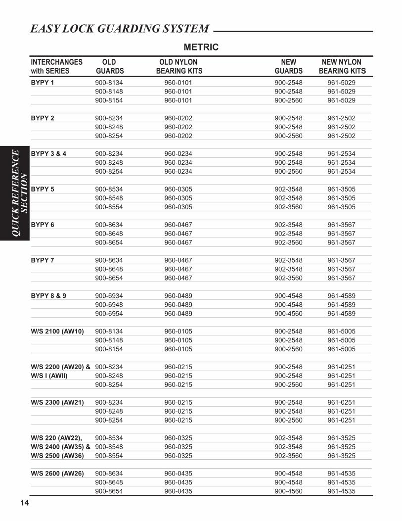
EASY LOCK GUARDING SYSTEM
14
QU
ICK
RE
FE
RE
NC
ESE
CTI
ON
INTERCHANGES OLD OLD NYLON NEW NEW NYLONwith SERIES GUARDS BEARING KITS GUARDS BEARING KITS
BYPY 1 900-8134 960-0101 900-2548 961-5029
900-8148 960-0101 900-2548 961-5029
900-8154 960-0101 900-2560 961-5029
BYPY 2 900-8234 960-0202 900-2548 961-2502
900-8248 960-0202 900-2548 961-2502
900-8254 960-0202 900-2560 961-2502
BYPY 3 & 4 900-8234 960-0234 900-2548 961-2534
900-8248 960-0234 900-2548 961-2534
900-8254 960-0234 900-2560 961-2534
BYPY 5 900-8534 960-0305 902-3548 961-3505
900-8548 960-0305 902-3548 961-3505
900-8554 960-0305 902-3560 961-3505
BYPY 6 900-8634 960-0467 902-3548 961-3567
900-8648 960-0467 902-3548 961-3567
900-8654 960-0467 902-3560 961-3567
BYPY 7 900-8634 960-0467 902-3548 961-3567
900-8648 960-0467 902-3548 961-3567
900-8654 960-0467 902-3560 961-3567
BYPY 8 & 9 900-6934 960-0489 900-4548 961-4589
900-6948 960-0489 900-4548 961-4589
900-6954 960-0489 900-4560 961-4589
W/S 2100 (AW10) 900-8134 960-0105 900-2548 961-5005
900-8148 960-0105 900-2548 961-5005
900-8154 960-0105 900-2560 961-5005
W/S 2200 (AW20) & 900-8234 960-0215 900-2548 961-0251
W/S I (AWII) 900-8248 960-0215 900-2548 961-0251
900-8254 960-0215 900-2560 961-0251
W/S 2300 (AW21) 900-8234 960-0215 900-2548 961-0251
900-8248 960-0215 900-2548 961-0251
900-8254 960-0215 900-2560 961-0251
W/S 220 (AW22), 900-8534 960-0325 902-3548 961-3525
W/S 2400 (AW35) & 900-8548 960-0325 902-3548 961-3525
W/S 2500 (AW36) 900-8554 960-0325 902-3560 961-3525
W/S 2600 (AW26) 900-8634 960-0435 900-4548 961-4535
900-8648 960-0435 900-4548 961-4535
900-8654 960-0435 900-4560 961-4535
METRIC
EASY LOCK GUARDING SYSTEM

15
QU
ICK
RE
FE
RE
NC
ESE
CTIO
N
INTERCHANGES W/ DIM A DIM B DIM A DIM BSTOCK No. SERIES INNER BRG. ID INNER BRG. OD OUTER BRG. ID OUTER BRG.OD960-0101 ByPy 1 34.8-mm (1.37") 57-mm (2.24") 40.8-mm (1.61") 57-mm (2.24”)
960-0202 ByPy 2 40.4-mm (1.59") 71.4-mm (2.81") 47.4-mm (1.87") 71.4-mm (2.81")
960-0234 ByPy 3 & 4 47.4-mm (1.87") 71.4-mm (2.81") 53.4-mm (2.10") 71.4-mm (2.81")
960-0305 ByPy 5 53.4-mm (2.10") 81.7-mm (3.22") 62.7-mm (2.47") 81.7-mm (3.22")
960-0467 ByPy 6 & 7 59.4-mm (2.34") 98.8-mm (3.89") 68.4-mm (2.69") 98.8-mm (3.89")
960-0489 ByPy 8 & 9 68.4-mm (2.69") 98.8-mm (3.89") 80.4-mm (3.17") 98.8-mm (3.89")
960-0105 W/S 2100 41.4-mm (1.63") 57-mm ((2.24") 41.4-mm (1.63") 57-mm ((2.24")
960-0215 W/S 2200, AW11,& W/S 2300 50.8-mm (2.00") 71.4-mm (2.81") 50.8-mm (2.00") 71.4-mm (2.81")
960-0325 W/S 220, W/S 2400,& W/S 2500 62.7-mm (2.47") 81.7-mm (3.22) 62.7-mm (2.47") 81.7-mm (3.22")
960-0435 W/S 2600 82.8-mm (3.26") 98.8-mm (3.89") 82.8-mm (3.26") 98.8-mm (3.89")
INTERCHANGES GUARD DIM A DIM B DIM A DIM BSTOCK No. W/SERIES TYPE INNER BRG. ID INNER BRG. OD OUTER BRG. ID OUTER BRG.OD961-3505 ByPy 5 350 53.5-mm (2.11") 83.6-mm (3.29") 62.7-mm (2.47") 83.6-mm (3.29")
961-3567 ByPy 6 & 7 350 59.4-mm (2.34") 83.6-mm (3.29") 68.4-mm (2.69") 83.6-mm (3.29")
961-4589 ByPy 8 & 9 450 68.4-mm (2.69") 103-mm (4.06") 80.4-mm (3.17") 103-mm (4.06")
961-3525 W/S 220, W/S 2400,& W/S 2500 350 62.5-mm (2.46") 83-mm (3.27") 62.5-mm (2.46") 83-mm (3.27")
961-4535 W/S 2600 450 82.8-mm (3.26") 103-mm (4.05") 82.8-mm (3.26") 103-mm (4.05")
GUARD DIM A DIM B DIM A DIM BSTOCK No. SERIES TYPE INNER BRG. ID INNER BRG. OD OUTER BRG. ID OUTER BRG.OD921-4400 44 & 55 350 67.2-mm (2.65") 83.6-mm (3.29") 67.2-mm (2.65") 83.6-mm (3.29")
INTERCHANGES GUARD DIM A DIM B DIM A DIM BSTOCK No. W/SERIES TYPE INNER BRG. ID INNER BRG. OD OUTER BRG. ID OUTER BRG.OD961-5029 ByPy 1 250 34.5-mm (1.36") 71.4-mm (2.81") 40.4 -mm(1.59") 71.4-mm (2.81")
961-2502 ByPy 2 250 40.4-mm (1.59") 71.4-mm (2.81") 47.4-mm (1.87") 71.4-mm (2.81")
961-2534 ByPy 3 & 4 250 47.4-mm (1.87") 71.4-mm (2.81") 53.4-mm (2.10") 71.4-mm (2.81")
961-5005 W/S 2100 250 41.4-mm (1.63") 71.4-mm (2.81") 41.4-mm (1.63") 71.4-mm (2.81")
961-0251 W/S 2200, W/S I & W/S 2300 250 50.8-mm (2.00") 71.4-mm (2.81") 50.8-mm (2.00") 71.4-mm (2.81")
GUARD DIM A DIM B DIM A DIM BSTOCK No. SERIES TYPE INNER BRG. ID INNER BRG. OD OUTER BRG. ID OUTER BRG.OD921-0600 6 250 46.4-mm (1.83") 71.4-mm (2.81") 46.4-mm (1.83") 71.4-mm (2.81")
921-1200 12, 14 & 35 250 52.8-mm (2.08") 71.4-mm (2.81") 52.8-mm (2.08") 71.4-mm (2.81")
921-5170 W 250 41.8-mm (1.65") 71.4-mm (2.81") 41.8-mm (1.65") 71.4-mm (2.81")
TYPE A - FITS 250 GUARDS
NORTH AMERICAN SERIES
NORTH AMERICAN SERIES
METRIC SERIES
METRIC SERIES
PREVIOUS-STYLE METRIC NYLON BEARING KIT
NYLON BEARING REPAIR KITS
TYPE B - FITS 350/450 GUARDS
TYPE C
EASY LOCK GUARDING SYSTEM

16
QU
ICK
RE
FE
RE
NC
ESE
CTI
ON
METAL RETAINING RING
920-0017 2.15" (2 5/32") 2.76" (2 3/4") .36" (23/64")
920-0069 1.77" (1 49/64") 2.76" (2 3/4") .36" (23/64")
920-0085 2.02" (2 1/64") 2.76" (2 3/4") .36" (23/64")
920-0102 1.41" (1 13/32") 2.02" (2 1/64") .30" (19/64")
920-0141 1.65" (1 21/32") 2.76" (2 3/4") .36" (23/64")
920-0165 2.15" (2 5/32") 3.26" (3 17/64") .36" (23/64")
920-0195 1.78" (1 25/32") 2.52" (2 33/64") .37" (3/8")
920-0254 1.64" (1 41/64") 2.25" (2 1/4") .29" (19/64")
920-0259 2.03" (2 1/32") 3.26" (3 17/64") .36" (23/64")
920-0260 1.39" (1 25/64") 2.77" (2 49/64") .36" (23/64")
920-0600 1.83" (1 53/64") 2.76" (2 3/4") .25" (1/4")
920-1200 2.09" (2 3/32") 2.77" (2 49/64") .32" (21/64")
920-2600 2.86" (2 55/64") 3.56" (3 9/16") .34" (11/32")
920-3500 2.08" (2 5/64") 2.76" (2 3/4") .32" (21/64")
920-4400 2.65" (2 21/32") 3.26" (3 17/64") .36" (23/64")
920-4P15 1.65" (1 21/32") 2.76" (2 3/4") .30" (19/64")
920-4P16 1.77" (1 49/64") 2.76" (2 3/4") .36" (23/64")
920-5071 2.02" (2 1/64") 2.76" (2 3/4") .36" (23/64")
920-5084 2.15" (2 5/32") 2.76" (2 3/4") .36" (23/64")
DIM A DIM CSTOCK YOKE RACEWAY O.D. DIM B YOKE RACEWAY WIDTHNUMBER NYLON BEARING I.D. NYLON BEARING O.D. NYLON BEARING WIDTH
PREVIOUS-STYLE NORTH AMERICAN NYLON BEARING KIT
(Kit includes nylon bearing and metal retaining ring)
EASY LOCK GUARDING SYSTEM
80° Constant Velocity Driveline
Constant Velocity Driveline Replacement ChartASAE Weasler ReplacementCategory Series For
3 14 Bondioli & Pavesi 4 SeriesWalterscheid 2380 Series
4 35 Bondioli & Pavesi 5 Series
5 35/44 Bondioli & Pavesi 6 SeriesWalterscheid 2480 Series
6 55 Bondioli & Pavesi 8 SeriesWalterscheid 2580 Series & 2680 Series
The above chart lists the approximate size replacement for Constant Velocity Drivelines. These are not an exact interchange, and should beused as a general replacement guide only. NOTE: 35/44 refers to CV Series. When CV is assembled with 44 Series tube end drivelinebecomes a 44 Series. When CV is assembled with a 35 Series tube end driveline is a 35 Series.
A = Overall Length B = Centerline Length
17
QU
ICK
RE
FE
RE
NC
ESE
CTIO
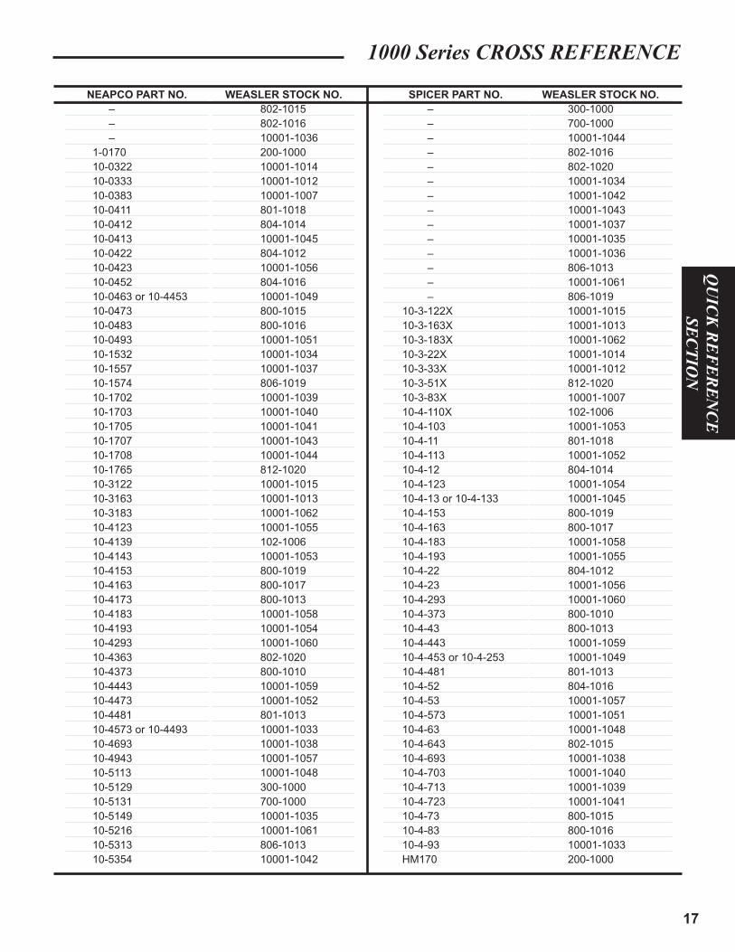
N1000 Series CROSS REFERENCE
NEAPCO PART NO.
–
–
–
1-0170
10-0322
10-0333
10-0383
10-0411
10-0412
10-0413
10-0422
10-0423
10-0452
10-0463 or 10-4453
10-0473
10-0483
10-0493
10-1532
10-1557
10-1574
10-1702
10-1703
10-1705
10-1707
10-1708
10-1765
10-3122
10-3163
10-3183
10-4123
10-4139
10-4143
10-4153
10-4163
10-4173
10-4183
10-4193
10-4293
10-4363
10-4373
10-4443
10-4473
10-4481
10-4573 or 10-4493
10-4693
10-4943
10-5113
10-5129
10-5131
10-5149
10-5216
10-5313
10-5354
WEASLER STOCK NO.
802-1015
802-1016
10001-1036
200-1000
10001-1014
10001-1012
10001-1007
801-1018
804-1014
10001-1045
804-1012
10001-1056
804-1016
10001-1049
800-1015
800-1016
10001-1051
10001-1034
10001-1037
806-1019
10001-1039
10001-1040
10001-1041
10001-1043
10001-1044
812-1020
10001-1015
10001-1013
10001-1062
10001-1055
102-1006
10001-1053
800-1019
800-1017
800-1013
10001-1058
10001-1054
10001-1060
802-1020
800-1010
10001-1059
10001-1052
801-1013
10001-1033
10001-1038
10001-1057
10001-1048
300-1000
700-1000
10001-1035
10001-1061
806-1013
10001-1042
WEASLER STOCK NO.
300-1000
700-1000
10001-1044
802-1016
802-1020
10001-1034
10001-1042
10001-1043
10001-1037
10001-1035
10001-1036
806-1013
10001-1061
806-1019
10001-1015
10001-1013
10001-1062
10001-1014
10001-1012
812-1020
10001-1007
102-1006
10001-1053
801-1018
10001-1052
804-1014
10001-1054
10001-1045
800-1019
800-1017
10001-1058
10001-1055
804-1012
10001-1056
10001-1060
800-1010
800-1013
10001-1059
10001-1049
801-1013
804-1016
10001-1057
10001-1051
10001-1048
802-1015
10001-1038
10001-1040
10001-1039
10001-1041
800-1015
800-1016
10001-1033
200-1000
SPICER PART NO.
–
–
–
–
–
–
–
–
–
–
–
–
–
–
10-3-122X
10-3-163X
10-3-183X
10-3-22X
10-3-33X
10-3-51X
10-3-83X
10-4-110X
10-4-103
10-4-11
10-4-113
10-4-12
10-4-123
10-4-13 or 10-4-133
10-4-153
10-4-163
10-4-183
10-4-193
10-4-22
10-4-23
10-4-293
10-4-373
10-4-43
10-4-443
10-4-453 or 10-4-253
10-4-481
10-4-52
10-4-53
10-4-573
10-4-63
10-4-643
10-4-693
10-4-703
10-4-713
10-4-723
10-4-73
10-4-83
10-4-93
HM170

18
QU
ICK
RE
FE
RE
NC
ESE
CTI
ON
Locking Device
Safety Slide LockAn exclusive Weasler replacement in the shaft for full contact. component, the Safety Slide Lock* The device is particularlyyoke is locked in place by two applicable where there is hardened pawls with compound appreciable end thrust.radii that conform to the groove
Spring-LokStock No. 13003100 Repair Kit for Weasler Spring-Lok
6 Spline & 21 Spline
Stock No. 13003115 1" × 15 Spline
Quick DisconnectStock No. 13002006 Repair Kit for Weasler
and Rockwell 6 SplineStock No. 13002806 Repair Kit for 1 3/4" × 6 Spl.
Stock No. 13002021 Weasler 21 Spline andHex Quick Disconnect
Stock No. 13002020 Weasler 20 Spline
Spring-LokThe collar is spring loaded forease of installation and positivelocking to tractor shaft.
Quick DisconnectA smooth plunger eliminatessharp projections such as x-washers. Trails rather thanleads rotation.
Locking Device Repair Kit
*Auto-Lok/Safety Slide LockStock No. 13004000 Repair Kit for Weasler Auto-Lok and
Safety Slide Lock6 Spline & 21 Spline
Stock No. 13004020 Repair Kit for Weasler Auto-Lok and Safety Slide Lock20 Spline
Stock No. 13004015 Repair Kit for1" × 15 Spline
* This repair kit contains both balls & pawls. When repairing the “Safety Slide Lock” use the pawls only and discard the balls.When repairing the “Auto-Lok” use both the balls and the pawls.

19
QU
ICK
RE
FE
RE
NC
ESE
CTIO
NCONVERSION TABLE
STANDARD UNIT CONVERSION
METRIC UNIT CONVERSION
1 inch = 25.4 mm
1 mm = 0.0394 inch
1 lb = 4.44 N
1 N = 0.225 lb
1 in•lb = 0.113 Nm
1 Nm = 0.738 ft•lb
1 Nm = 8.85 in•lb
1 HP = 0.746 kW
1 kW = 1.341 HP
1 Kg = 2.305 lb
1 lb = 0.454 Kg
1 ft•lb = 1.356 Nm
1 M = 1000 mm
1 ft = 12 inches
1 kW = 1000 Watts
Power (HP) = Torque (in•lb) x Shaft Speed (RPM)
63,000
Torque (in•lb) = Power (HP) x 63,000
Shaft Speed (RPM)
Power (kW) = Torque (Nm) x Shaft Speed (RPM)
0.00955
Torque (Nm) = Power (kW) x 0.00955
Shaft Speed (RPM)

20
QU
ICK
RE
FE
RE
NC
ESE
CTI
ON
N O T E S