P5AD2-E - Asus...4.5.2 Repost Video on S3 Resume .....4-33 4.5.3 ACPI 2.0 Support.....4-33 4.5.4...
166
Motherboard P5AD2-E Premium
Transcript of P5AD2-E - Asus...4.5.2 Repost Video on S3 Resume .....4-33 4.5.3 ACPI 2.0 Support.....4-33 4.5.4...

Mot
herb
oard
P5AD2-EPremium
i ii ii ii ii i
E1998E1998E1998E1998E1998
Revised Edit ion V2Revised Edit ion V2Revised Edit ion V2Revised Edit ion V2Revised Edit ion V2March 2005March 2005March 2005March 2005March 2005
Copyr ight © 2005 ASUSTeK COMPUTER INC . A l l R i ghts Rese rved .Copy r ight © 2005 ASUSTeK COMPUTER INC . A l l R i ghts Rese rved .Copy r ight © 2005 ASUSTeK COMPUTER INC . A l l R i ghts Rese rved .Copy r ight © 2005 ASUSTeK COMPUTER INC . A l l R i ghts Rese rved .Copy r ight © 2005 ASUSTeK COMPUTER INC . A l l R i ghts Rese rved .
No part of this manual, including the products and software described in it, may be reproduced,transmitted, transcribed, stored in a retrieval system, or translated into any language in any formor by any means, except documentation kept by the purchaser for backup purposes, without theexpress written permission of ASUSTeK COMPUTER INC. (“ASUS”).
Product warranty or service will not be extended if: (1) the product is repaired, modified oraltered, unless such repair, modification of alteration is authorized in writing by ASUS; or (2)the serial number of the product is defaced or missing.
ASUS PROVIDES THIS MANUAL “AS IS” WITHOUT WARRANTY OF ANY KIND, EITHEREXPRESS OR IMPLIED, INCLUDING BUT NOT LIMITED TO THE IMPLIED WARRANTIESOR CONDITIONS OF MERCHANTABILITY OR FITNESS FOR A PARTICULAR PURPOSE.IN NO EVENT SHALL ASUS, ITS DIRECTORS, OFFICERS, EMPLOYEES OR AGENTS BELIABLE FOR ANY INDIRECT, SPECIAL, INCIDENTAL, OR CONSEQUENTIAL DAMAGES(INCLUDING DAMAGES FOR LOSS OF PROFITS, LOSS OF BUSINESS, LOSS OF USEOR DATA, INTERRUPTION OF BUSINESS AND THE LIKE), EVEN IF ASUS HAS BEENADVISED OF THE POSSIBILITY OF SUCH DAMAGES ARISING FROM ANY DEFECT ORERROR IN THIS MANUAL OR PRODUCT.
SPECIFICATIONS AND INFORMATION CONTAINED IN THIS MANUAL ARE FURNISHEDFOR INFORMATIONAL USE ONLY, AND ARE SUBJECT TO CHANGE AT ANY TIMEWITHOUT NOTICE, AND SHOULD NOT BE CONSTRUED AS A COMMITMENT BY ASUS.ASUS ASSUMES NO RESPONSIBILITY OR LIABILITY FOR ANY ERRORS ORINACCURACIES THAT MAY APPEAR IN THIS MANUAL, INCLUDING THE PRODUCTSAND SOFTWARE DESCRIBED IN IT.
Products and corporate names appearing in this manual may or may not be registeredtrademarks or copyrights of their respective companies, and are used only for identification orexplanation and to the owners’ benefit, without intent to infringe.

i i ii i ii i ii i ii i i
Contents
Notices ................................................................................................ vi
Safety information ............................................................................. vii
About this guide ............................................................................... viii
P5AD2-E Premium specifications summary ......................................... x
Chapter 1:Chapter 1:Chapter 1:Chapter 1:Chapter 1: Product introductionProduct introductionProduct introductionProduct introductionProduct introduction
1.1 Welcome! .............................................................................. 1-1
1.2 Package contents ................................................................. 1-1
1.3 Special features .................................................................... 1-2
1.3.1 Product highlights ................................................... 1-2
1.3.2 ASUS AI Proactive features .................................... 1-5
1.3.3 Innovative ASUS features ....................................... 1-6
Chapter 2:Chapter 2:Chapter 2:Chapter 2:Chapter 2: Hardware informationHardware informationHardware informationHardware informationHardware information
2.1 Before you proceed .............................................................. 2-1
2.2 Motherboard ovessrview ...................................................... 2-2
2.2.1 Placement direction ................................................ 2-2
2.2.2 Screw holes ............................................................ 2-2
2.2.3 ASUS Stack Cool ..................................................... 2-3
2.2.4 Motherboard layout ................................................ 2-4
2.2.5 Layout contents ..................................................... 2-5
2.3 Central Processing Unit (CPU) .............................................. 2-7
2.3.1 Installing the CPU.................................................... 2-7
2.3.2 Installing the CPU heatsink and fan ...................... 2-10
2.3.3 Uninstalling the CPU heatsink and fan .................. 2-12
2.4 System memory ................................................................. 2-14
2.4.1 Overview ............................................................... 2-14
2.4.2 Memory configurations ......................................... 2-14
2.4.3 Installing a DIMM ................................................... 2-17
2.4.4 Removing a DIMM ................................................. 2-17
2.5 Expansion slots ................................................................... 2-18
2.5.1 Installing an expansion card .................................. 2-18
2.5.2 Configuring an expansion card.............................. 2-18
2.5.3 Interrupt assignments .......................................... 2-19
2.5.4 PCI slots ................................................................ 2-20
2.5.5 PCI Express x16 slot ............................................. 2-20
2.5.6 PCI Express x1 slot ............................................... 2-20
2.6 Jumpers .............................................................................. 2-21
2.7 Connectors ......................................................................... 2-23
2.7.1 Rear panel connectors .......................................... 2-23
2.7.2 Internal connectors............................................... 2-25
i vi vi vi vi v
Contents
Chapter 3:Chapter 3:Chapter 3:Chapter 3:Chapter 3: Powering upPowering upPowering upPowering upPowering up
3.1 Starting up for the first time ................................................ 3-1
3.2 Powering off the computer .................................................. 3-2
3.2.1 Using the OS shut down function ........................... 3-2
3.2.2 Using the dual function power switch .................... 3-2
3.3 ASUS POST Reporter™ .......................................................... 3-3
3.3.1 Vocal POST messages ............................................ 3-3
3.3.2 Winbond Voice Editor ............................................. 3-5
Chapter 4:Chapter 4:Chapter 4:Chapter 4:Chapter 4: BIOS setupBIOS setupBIOS setupBIOS setupBIOS setup
4.1 Managing and updating your BIOS ........................................ 4-1
4.1.1 Creating a bootable floppy disk .............................. 4-1
4.1.2 AFUDOS utility ........................................................ 4-2
4.1.3 ASUS CrashFree BIOS 2 utility ................................ 4-5
4.1.4 ASUS EZ Flash utility .............................................. 4-7
4.1.5 ASUS Update utility ................................................ 4-8
4.2 BIOS setup program ........................................................... 4-11
4.2.2 Menu bar ............................................................... 4-12
4.2.3 Navigation keys .................................................... 4-12
4.2.1 BIOS menu screen ................................................. 4-12
4.2.4 Menu items ........................................................... 4-13
4.2.5 Sub-menu items ................................................... 4-13
4.2.6 Configuration fields .............................................. 4-13
4.2.7 Pop-up window ..................................................... 4-13
4.2.8 Scroll bar .............................................................. 4-13
4.2.9 General help .......................................................... 4-13
4.3 Main menu .......................................................................... 4-14
4.3.1 System Time......................................................... 4-14
4.3.2 System Date ......................................................... 4-14
4.3.3 Legacy Diskette A ................................................ 4-14
4.3.4 Language .............................................................. 4-14
4.3.5 Primary, Third and Fourth IDE Master/Slave ......... 4-15
4.3.6 IDE Configuration .................................................. 4-16
4.3.7 System Information .............................................. 4-18
4.4 Advanced menu .................................................................. 4-19
4.4.1 JumperFree Configuration .................................... 4-19
4.4.2 LAN Cable Status ................................................. 4-23
4.4.3 USB Configuration ................................................. 4-24
4.4.4 CPU Configuration ................................................. 4-25
4.4.5 Chipset ................................................................. 4-27

vvvvv
Contents
4.4.6 Onboard Devices Configuration ............................ 4-29
4.4.7 PCI PnP ................................................................. 4-31
4.4.8 Speech Configuration ........................................... 4-32
4.5 Power menu ........................................................................ 4-33
4.5.1 Suspend Mode ...................................................... 4-33
4.5.2 Repost Video on S3 Resume ................................ 4-33
4.5.3 ACPI 2.0 Support .................................................. 4-33
4.5.4 ACPI APIC Support ................................................ 4-33
4.5.5 APM Configuration ................................................ 4-34
4.5.6 Hardware Monitor ................................................. 4-36
4.6 Boot menu .......................................................................... 4-38
4.6.1 Boot Device Priority .............................................. 4-38
4.6.2 Boot Settings Configuration ................................. 4-39
4.6.3 Security ................................................................ 4-40
4.7 Exit menu ........................................................................... 4-43
Chapter 5:Chapter 5:Chapter 5:Chapter 5:Chapter 5: Software supportSoftware supportSoftware supportSoftware supportSoftware support
5.1 Installing an operating system ............................................. 5-1
5.2 Support CD information ........................................................ 5-1
5.2.1 Running the support CD ......................................... 5-1
5.2.2 Drivers menu .......................................................... 5-2
5.2.3 Utilities menu .......................................................... 5-4
5.2.4 Manuals menu ......................................................... 5-5
5.2.5 Contact information ............................................... 5-6
5.2.6 Other information ................................................... 5-6
5.3 IEEE 1394b driver information ............................................. 5-8
5.4 Software information ......................................................... 5-11
5.4.1 ASUS MyLogo2™ .................................................. 5-11
5.4.2 AI NET2 ................................................................ 5-13
5.4.3 C-Media 3D audio configuration ........................... 5-14
5.5 RAID configurations ............................................................ 5-19
5.5.1 Installing hard disks .............................................. 5-20
5.5.2 Silicon Image RAID configurations ........................ 5-21
5.5.3 Intel® RAID configurations .................................... 5-31
5.5.4 ITE® 8212F RAID configurations ........................... 5-36
5.6 Creating a RAID driver disk ................................................. 5-42
Appendix:Appendix:Appendix:Appendix:Appendix: CPU featuresCPU featuresCPU featuresCPU featuresCPU features
A.1 Intel® EM64T ........................................................................ A-1
A.2 Enhanced Intel SpeedStep® Technology (EIST) .................... A-1
A.3 Intel® Hyper-Threading Technology ...................................... A-3

v iv iv iv iv i
Notices
Federal Communications Commission StatementFederal Communications Commission StatementFederal Communications Commission StatementFederal Communications Commission StatementFederal Communications Commission Statement
This device complies with Part 15 of the FCC Rules. Operation is subject tothe following two conditions:
• This device may not cause harmful interference, and
• This device must accept any interference received including interferencethat may cause undesired operation.
This equipment has been tested and found to comply with the limits for aClass B digital device, pursuant to Part 15 of the FCC Rules. These limits aredesigned to provide reasonable protection against harmful interference in aresidential installation. This equipment generates, uses and can radiate radiofrequency energy and, if not installed and used in accordance withmanufacturer’s instructions, may cause harmful interference to radiocommunications. However, there is no guarantee that interference will notoccur in a particular installation. If this equipment does cause harmfulinterference to radio or television reception, which can be determined byturning the equipment off and on, the user is encouraged to try to correctthe interference by one or more of the following measures:
• Reorient or relocate the receiving antenna.
• Increase the separation between the equipment and receiver.
• Connect the equipment to an outlet on a circuit different from that towhich the receiver is connected.
• Consult the dealer or an experienced radio/TV technician for help.
Canadian Department of Communications StatementCanadian Department of Communications StatementCanadian Department of Communications StatementCanadian Department of Communications StatementCanadian Department of Communications Statement
This digital apparatus does not exceed the Class B limits for radio noiseemissions from digital apparatus set out in the Radio InterferenceRegulations of the Canadian Department of Communications.
This class B digital apparatus complies with CanadianThis class B digital apparatus complies with CanadianThis class B digital apparatus complies with CanadianThis class B digital apparatus complies with CanadianThis class B digital apparatus complies with CanadianICES-003.ICES-003.ICES-003.ICES-003.ICES-003.
The use of shielded cables for connection of the monitor to the graphicscard is required to assure compliance with FCC regulations. Changes ormodifications to this unit not expressly approved by the partyresponsible for compliance could void the user’s authority to operatethis equipment.

v i iv i iv i iv i iv i i
Safety information
Electrical safetyElectrical safetyElectrical safetyElectrical safetyElectrical safety
• To prevent electrical shock hazard, disconnect the power cable fromthe electrical outlet before relocating the system.
• When adding or removing devices to or from the system, ensure thatthe power cables for the devices are unplugged before the signal cablesare connected. If possible, disconnect all power cables from the existingsystem before you add a device.
• Before connecting or removing signal cables from the motherboard,ensure that all power cables are unplugged.
• Seek professional assistance before using an adpater or extension cord.These devices could interrupt the grounding circuit.
• Make sure that your power supply is set to the correct voltage in yourarea. If you are not sure about the voltage of the electrical outlet youare using, contact your local power company.
• If the power supply is broken, do not try to fix it by yourself. Contact aqualified service technician or your retailer.
Operation safetyOperation safetyOperation safetyOperation safetyOperation safety
• Before installing the motherboard and adding devices on it, carefully readall the manuals that came with the package.
• Before using the product, make sure all cables are correctly connectedand the power cables are not damaged. If you detect any damage,contact your dealer immediately.
• To avoid short circuits, keep paper clips, screws, and staples away fromconnectors, slots, sockets and circuitry.
• Avoid dust, humidity, and temperature extremes. Do not place theproduct in any area where it may become wet.
• Place the product on a stable surface.
• If you encounter technical problems with the product, contact a qualifiedservice technician or your retailer.

v i i iv i i iv i i iv i i iv i i i
About this guide
This user guide contains the information you need when installing andconfiguring the motherboard.
How this guide is organizedHow this guide is organizedHow this guide is organizedHow this guide is organizedHow this guide is organized
This guide contains the following parts:
••••• Chapter 1: Product introduct ionChapter 1: Product introduct ionChapter 1: Product introduct ionChapter 1: Product introduct ionChapter 1: Product introduct ion
This chapter describes the features of the motherboard and the newtechnology it supports.
••••• Chapter 2: Hardware informat ionChapter 2: Hardware informat ionChapter 2: Hardware informat ionChapter 2: Hardware informat ionChapter 2: Hardware informat ion
This chapter lists the hardware setup procedures that you have toperform when installing system components. It includes description ofthe switches, jumpers, and connectors on the motherboard.
••••• Chapter 3: Power ing upChapter 3: Power ing upChapter 3: Power ing upChapter 3: Power ing upChapter 3: Power ing up
This chapter describes the power up sequence, the vocal POSTmessages, and ways of shutting down the system.
••••• Chapter 4: B IOS setupChapter 4: B IOS setupChapter 4: B IOS setupChapter 4: B IOS setupChapter 4: B IOS setup
This chapter tells how to change system settings through the BIOSSetup menus. Detailed descriptions of the BIOS parameters are alsoprovided.
••••• Chapter 5: Software supportChapter 5: Software supportChapter 5: Software supportChapter 5: Software supportChapter 5: Software support
This chapter describes the contents of the support CD that comeswith the motherboard package.
••••• Appendix: CPU featuresAppendix: CPU featuresAppendix: CPU featuresAppendix: CPU featuresAppendix: CPU features
The Appendix describes the CPU features that the motherboardsupports.
Where to find more informationWhere to find more informationWhere to find more informationWhere to find more informationWhere to find more information
Refer to the following sources for additional information and for productand software updates.
1 .1 .1 .1 .1 . ASUS webs itesASUS webs itesASUS webs itesASUS webs itesASUS webs ites
The ASUS website provides updated information on ASUS hardwareand software products. Refer to the ASUS contact information.
2 .2 .2 .2 .2 . Opt ional documentat ionOpt ional documentat ionOpt ional documentat ionOpt ional documentat ionOpt ional documentat ion
Your product package may include optional documentation, such aswarranty flyers, that may have been added by your dealer. Thesedocuments are not part of the standard package.
i xi xi xi xi x
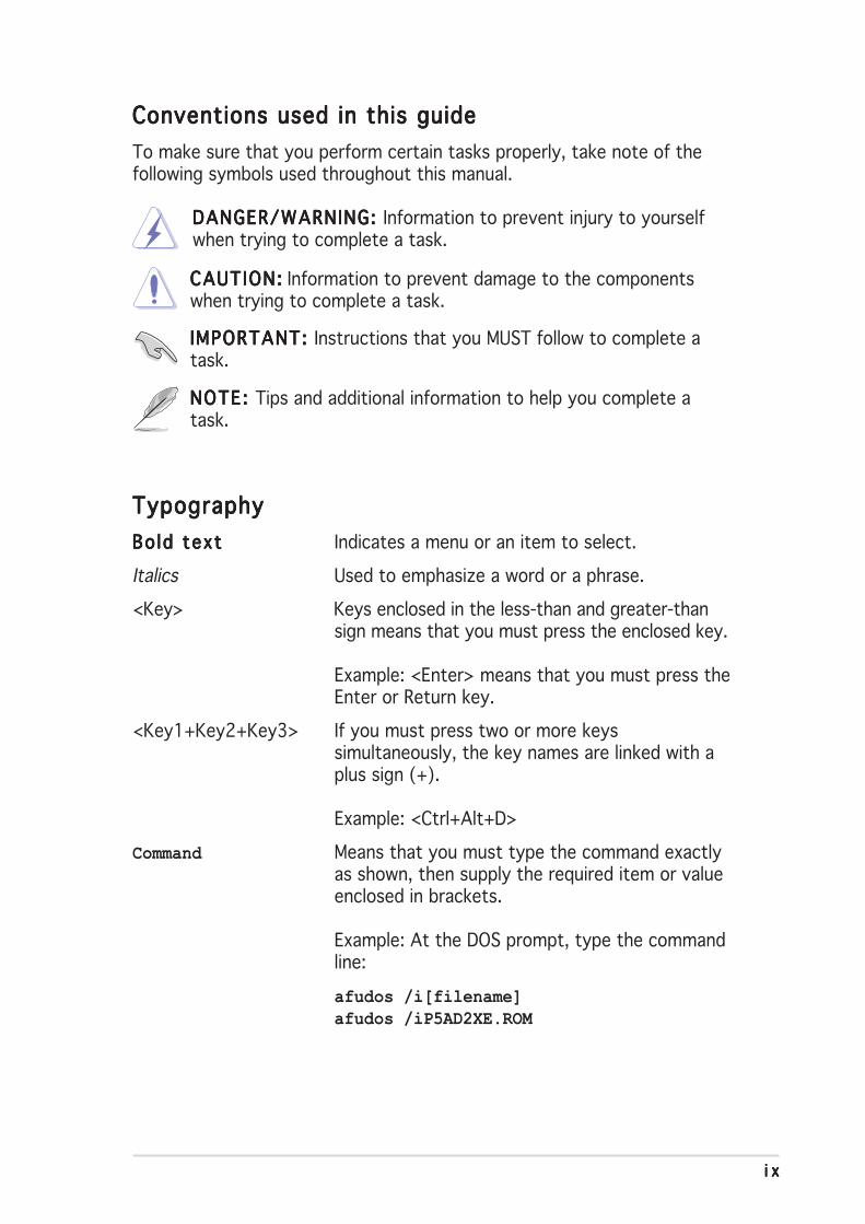
Conventions used in this guideConventions used in this guideConventions used in this guideConventions used in this guideConventions used in this guide
To make sure that you perform certain tasks properly, take note of thefollowing symbols used throughout this manual.
TypographyTypographyTypographyTypographyTypography
Bold textBo ld textBo ld textBo ld textBo ld text Indicates a menu or an item to select.
Italics Used to emphasize a word or a phrase.
<Key> Keys enclosed in the less-than and greater-thansign means that you must press the enclosed key.
Example: <Enter> means that you must press theEnter or Return key.
<Key1+Key2+Key3> If you must press two or more keyssimultaneously, the key names are linked with aplus sign (+).
Example: <Ctrl+Alt+D>
Command Means that you must type the command exactlyas shown, then supply the required item or valueenclosed in brackets.
Example: At the DOS prompt, type the commandline:
afudos /i[filename]afudos /iP5AD2XE.ROM
DANGER/WARNING: DANGER/WARNING: DANGER/WARNING: DANGER/WARNING: DANGER/WARNING: Information to prevent injury to yourselfwhen trying to complete a task.
CAUTION:CAUTION:CAUTION:CAUTION:CAUTION: Information to prevent damage to the componentswhen trying to complete a task.
NOTE: NOTE: NOTE: NOTE: NOTE: Tips and additional information to help you complete atask.
IMPORTANT: IMPORTANT: IMPORTANT: IMPORTANT: IMPORTANT: Instructions that you MUST follow to complete atask.

xxxxx
P5AD2-E Premium specifications summary
(continued on the next page)
C P UC P UC P UC P UC P U
Ch ipsetCh ipsetCh ipsetCh ipsetCh ipset
Front S ide BusFront S ide BusFront S ide BusFront S ide BusFront S ide Bus
MemoryMemoryMemoryMemoryMemory
Expans ion s lotsExpans ion s lotsExpans ion s lotsExpans ion s lotsExpans ion s lots
Sto rageSto rageSto rageSto rageSto rage
Wi re less LANWi re less LANWi re less LANWi re less LANWi re less LAN(opt iona l )(opt iona l )(opt iona l )(opt iona l )(opt iona l )
H igh Def in i t ionH igh Def in i t ionH igh Def in i t ionH igh Def in i t ionH igh Def in i t ionAud i oAud i oAud i oAud i oAud i o
U S BU S BU S BU S BU S B
LGA775 socket for Intel® Pentium® 4/Celeron processorCompatible with Intel® PCG 04A and 04B processorsSupports Intel® Enhanced Memory 64Technology (EM64T)Supports Enhanced Intel SpeedStep® Technology (EIST)Supports Intel® Hyper-Threading Technology
Northbridge: Intel® 925XE Memory Controller Hub (MCH)Southbridge: Intel® ICH6R
1066/800 MHz
Dual-channel memory architecture4 x 240-pin DIMM sockets support unbufferred non-ECC
DDR2-711 (FSB 1066)/DDR2-600 (FSB 800)/DDR2-533 (FSB 1066/800) MHz memory modules
Up to 4 GB system memoryNative DDR2-711/600 support
1 x PCI Express x16 slot2 x PCI Express x1 slots3 x PCI slots
Intel® ICH6R South Bridge supports:- 1 x Ultra DMA 100/66/33 hard disk- 4 x Serial ATA hard disks with RAID 0, RAID 1
configuration and Intel® Matrix Storage Technology
Silicon Image 3114R RAID controller supports:- 4 x Serial ATA hard disks with RAID 0, RAID 1,
RAID 10, and RAID 5 (software patch, no WHQL)configuration
ITE 8212F IDE RAID controller supports:- 2 x Ultra DMA 133/100/66 hard disks- RAID 0, RAID 1, RAID 0+1, and JBOD configuration
WiFi-g™ wireless solution provides:- support for IEEE 802.11g/b standards- up to 54Mbps wireless data transmission- Software Access Point (Soft AP) feature on
Windows® XP/2003 Server OS
Intel® High Definition Audio (HD Audio)C-Media CMI9880 7.1-channel audio CODECDolby® Digital Live™ technology supportCoaxial and optical S/PDIF out portsS/PDIF In connector at midboard
Supports up to 8 USB 2.0 ports
x ix ix ix ix i
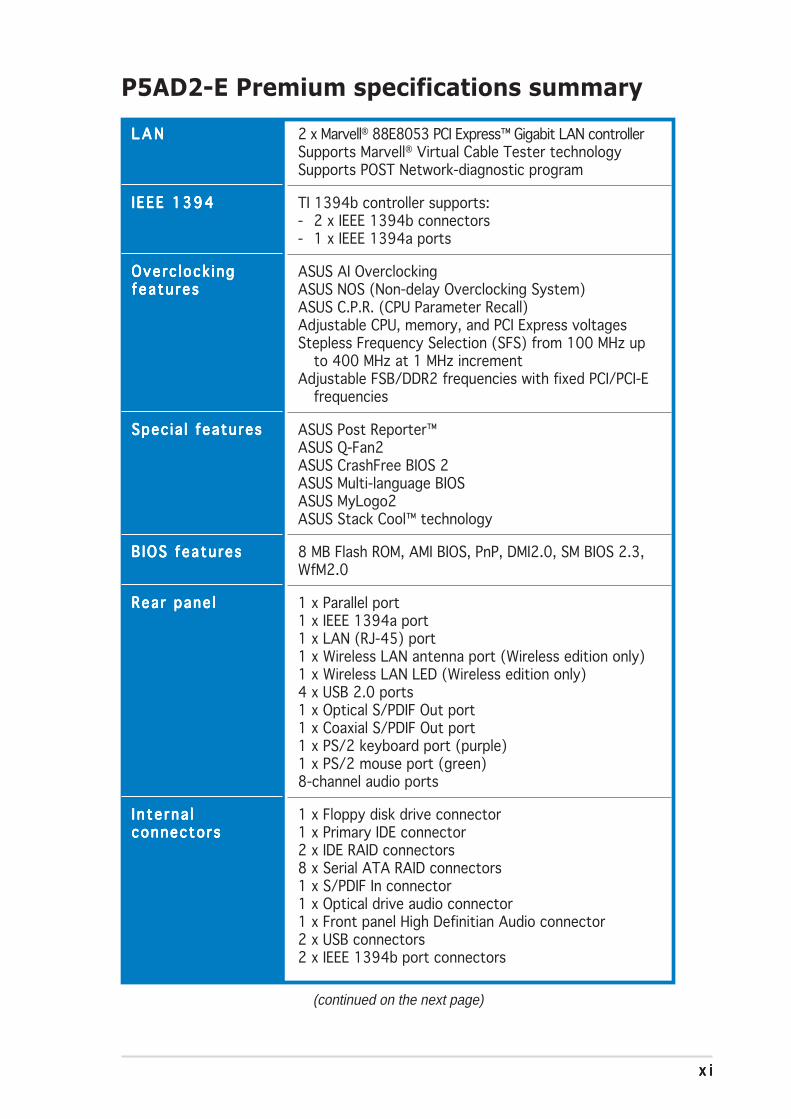
2 x Marvell® 88E8053 PCI Express™ Gigabit LAN controllerSupports Marvell® Virtual Cable Tester technologySupports POST Network-diagnostic program
TI 1394b controller supports:- 2 x IEEE 1394b connectors- 1 x IEEE 1394a ports
ASUS AI OverclockingASUS NOS (Non-delay Overclocking System)ASUS C.P.R. (CPU Parameter Recall)Adjustable CPU, memory, and PCI Express voltagesStepless Frequency Selection (SFS) from 100 MHz up
to 400 MHz at 1 MHz incrementAdjustable FSB/DDR2 frequencies with fixed PCI/PCI-E
frequencies
ASUS Post Reporter™ASUS Q-Fan2ASUS CrashFree BIOS 2ASUS Multi-language BIOSASUS MyLogo2ASUS Stack Cool™ technology
8 MB Flash ROM, AMI BIOS, PnP, DMI2.0, SM BIOS 2.3,WfM2.0
1 x Parallel port1 x IEEE 1394a port1 x LAN (RJ-45) port1 x Wireless LAN antenna port (Wireless edition only)1 x Wireless LAN LED (Wireless edition only)4 x USB 2.0 ports1 x Optical S/PDIF Out port1 x Coaxial S/PDIF Out port1 x PS/2 keyboard port (purple)1 x PS/2 mouse port (green)8-channel audio ports
1 x Floppy disk drive connector1 x Primary IDE connector2 x IDE RAID connectors8 x Serial ATA RAID connectors1 x S/PDIF In connector1 x Optical drive audio connector1 x Front panel High Definitian Audio connector2 x USB connectors2 x IEEE 1394b port connectors
P5AD2-E Premium specifications summary
(continued on the next page)
L A NL A NL A NL A NL A N
IEEE 1394IEEE 1394IEEE 1394IEEE 1394IEEE 1394
Overc lock ingOverc lock ingOverc lock ingOverc lock ingOverc lock ingfeatu resfeatu resfeatu resfeatu resfeatu res
Spec ia l featuresSpec ia l featuresSpec ia l featuresSpec ia l featuresSpec ia l features
B IOS featuresB IOS featuresB IOS featuresB IOS featuresB IOS features
Rear pane lRear pane lRear pane lRear pane lRear pane l
I n te rna lI n te rna lI n te rna lI n te rna lI n te rna lconnectorsconnectorsconnectorsconnectorsconnectors

x i ix i ix i ix i ix i i
P5AD2-E Premium specifications summary
I n te rna lI n te rna lI n te rna lI n te rna lI n te rna lconnectorsconnectorsconnectorsconnectorsconnectors(cont inuat ion)(cont inuat ion)(cont inuat ion)(cont inuat ion)(cont inuat ion)
Powe rPowe rPowe rPowe rPowe rRequ i rementRequ i rementRequ i rementRequ i rementRequ i rement
Form FactorForm FactorForm FactorForm FactorForm Factor
Support CDSupport CDSupport CDSupport CDSupport CDcontentscontentscontentscontentscontents
1 x GAME/MIDI port connector1 x Serial port connector1 x Gigabit LAN connectorChassis intrusion connectorCPU, chassis (x2), and power fan connectorsATX power connectors (24-pin and 4-pin)System panel connector
ATX power supply (with 24-pin and 4-pin 12 V plugs)ATX 12 V 2.0 compliant
ATX form factor: 12 in x 9.6 in (30.5 cm x 24.4 cm)
Device driversASUS PC ProbeASUS UpdateASUS AI BoosterMicrosoft® DirectX 9.0cASUS WiFi-g™ One-Touch WizardAnti-Virus UtilityWinbond Voice EditorAdobe Acrobat ReaderASUS Screensaver
*Specifications are subject to change without notice.

1Productintroduction
This chapter describes the motherboardfeatures and the new technologiesit supports.

ASUS P5AD2-E PremiumASUS P5AD2-E PremiumASUS P5AD2-E PremiumASUS P5AD2-E PremiumASUS P5AD2-E Premium
Chapter summary 11.1 Welcome! .............................................................................. 1-1
1.2 Package contents ................................................................. 1-1
1.3 Special features .................................................................... 1-2
ASUS P5AD2-E PremiumASUS P5AD2-E PremiumASUS P5AD2-E PremiumASUS P5AD2-E PremiumASUS P5AD2-E Premium 1 - 11 - 11 - 11 - 11 - 1
1.1 Welcome!
Thank you for buying an ASUSThank you for buying an ASUSThank you for buying an ASUSThank you for buying an ASUSThank you for buying an ASUS®®®®® P5AD2-E Premium motherboard! P5AD2-E Premium motherboard! P5AD2-E Premium motherboard! P5AD2-E Premium motherboard! P5AD2-E Premium motherboard!
The motherboard delivers a host of new features and latest technologies,making it another standout in the long line of ASUS quality motherboards!
Before you start installing the motherboard, and hardware devices on it,check the items in your package with the list below.
1.2 Package contents
Check your motherboard package for the following items.
MotherboardMotherboardMotherboardMotherboardMotherboard ASUS P5AD2-E Premium motherboard
I/O modulesI/O modulesI/O modulesI/O modulesI/O modules IEEE1394b (2 ports) and RJ-45 (1 port) module
Serial (COM2) port module
Serial ATA extension (2 ports) module
USB 2.0 (2 ports) and GAME (1 port) module
Cab lesCab lesCab lesCab lesCab les 10 x Serial ATA signal cables
4 x Serial ATA power cables (dual plugs)
2 x Ultra DMA/133 cables
40-conductor IDE cable
Floppy disk drive cable
Accessor iesAccessor iesAccessor iesAccessor iesAccessor ies Dipolar wireless LAN antenna (Wireless Edition only)
I/O shield
Appl icat ion CDsAppl icat ion CDsAppl icat ion CDsAppl icat ion CDsAppl icat ion CDs ASUS motherboard support CD
InterVideo® WinDVD Suite® Platinum (Retail version only)
Documentat ionDocumentat ionDocumentat ionDocumentat ionDocumentat ion User guide
If any of the above items is damaged or missing, contact your retailer.
1 - 21 - 21 - 21 - 21 - 2 Chapter 1 : Product int roduct ionChapter 1 : Product int roduct ionChapter 1 : Product int roduct ionChapter 1 : Product int roduct ionChapter 1 : Product int roduct ion
1.3 Special features
1.3.11.3.11.3.11.3.11.3.1 Product highlightsProduct highlightsProduct highlightsProduct highlightsProduct highlights
Latest processor technology Latest processor technology Latest processor technology Latest processor technology Latest processor technology
The motherboard comes with a 775-pin surface mount Land Grid Array(LGA) socket designed for the Intel® Pentium® 4 processor in the 775-landpackage. The motherboard supports the Intel® Pentium® 4 processor with1066/800/533 MHz Front Side Bus (FSB). The motherboard also supportsthe Intel® Hyper-Threading Technology and is fully compatible with Intel®
04B and 04A processors. See page 2-7 for details.
IntelIntelIntelIntelIntel®®®®® EM64T EM64T EM64T EM64T EM64T
The motherboard supports Intel® Pentium® 4 CPUs with the Intel® EM64T(Extended Memory 64 Technology). The Intel® EM64T feature allows yourcomputer to run on 64-bit operating systems and access larger amounts ofsystem memory for faster and more efficient computing. See the Appendixfor details.
Enhanced Intel SpeedStepEnhanced Intel SpeedStepEnhanced Intel SpeedStepEnhanced Intel SpeedStepEnhanced Intel SpeedStep® Technology (EIST) Technology (EIST) Technology (EIST) Technology (EIST) Technology (EIST)
The Enhanced Intel SpeedStep® Technology (EIST) intelligently managesthe CPU resources by automatically adjusting the CPU voltage and corefrequency depending on the CPU loading and system speed or powerrequirement. See page 4-26 and the Appendix for details.
IntelIntelIntelIntelIntel® 925XE chipset 925XE chipset 925XE chipset 925XE chipset 925XE chipset
The Intel® 925XE Memory Controller Hub (MCH) and the ICH6R I/Ocontroller hub provide the vital interfaces for the motherboard. The MCHsupports the Intel® Performance Accelerating Technology (PAT) thatboosts system performance. The MCH also provides the processor,dual-channel memory, and PCI Express interfaces.
The Intel® ICH6R Southbridge represents the sixth generation I/O controllerhub that provides the interface for the storage, I/O, PCI Express, and8-channel high definition audio interfaces.
DDR2 memory support DDR2 memory support DDR2 memory support DDR2 memory support DDR2 memory support
The motherboard supports DDR2 memory which features data transfer ratesof 711 MHz (FSB 1066), 600 MHz (FSB 800), or 533 MHz (FSB 1066/800) to meet the higher bandwidth requirements of the latest 3D graphics,multimedia, and Internet applications. The dual-channel DDR2 architecturedoubles the bandwidth of your system memory to boost system performance,eliminating bottlenecks with peak bandwidths of up to 8.5 GB/s. See pages2-14 to 2-17 for details.
ASUS P5AD2-E PremiumASUS P5AD2-E PremiumASUS P5AD2-E PremiumASUS P5AD2-E PremiumASUS P5AD2-E Premium 1 - 31 - 31 - 31 - 31 - 3
Serial ATA technology Serial ATA technology Serial ATA technology Serial ATA technology Serial ATA technology
The motherboard supports the Serial ATA technology through the Serial ATAinterfaces and the Intel® ICH6R. The SATA specification allows for thinner,more flexible cables with lower pin count, reduced voltage requirement, andup to 150 MB/s data transfer rate. See pages 2-27 and 2-28 for details.
Triple RAID solution Triple RAID solution Triple RAID solution Triple RAID solution Triple RAID solution
Onboard RAID controllers provide the motherboard with multi-RAIDfunctionality that allows you to select the best RAID solution using IDE orSerial ATA hard disk drives.
The Intel® ICH6R allows RAID 0 and RAID 1 configuration for four SATAconnectors and supports the Intel® Matrix Storage Technology. See pages2-27 and 5-31 for details.
The Sil3114R controller supports four additional SATA connectors andallows RAID 0, RAID 1, RAID 10, and a software patch to support RAID 5.See pages 2-28 and 5-21 for details.
If you are using IDE hard disk drives, the ITE8212 controller providesRAID 0, RAID 1, RAID 0+1, and JBOD functionality for two IDE channelsthat supports for up to four IDE hard disk drives. See pages 2-26 and 5-36for details.
PCI Express™ interface PCI Express™ interface PCI Express™ interface PCI Express™ interface PCI Express™ interface
The motherboard fully supports PCI Express, the latest I/O interconnecttechnology that speeds up the PCI bus. PCI Express features point-to-pointserial interconnections between devices and allows higher clockspeeds bycarrying data in packets. This high speed interface is software compatible withexisting PCI specifications. See page 2-20 for details.
8-channel high definition audio 8-channel high definition audio 8-channel high definition audio 8-channel high definition audio 8-channel high definition audio
Onboard is the C-Media CMI9880 7.1-channel audio CODEC. This CODEC isfully-compliant with Intel® High Definition Audio standard (192 KHz, 24-bitaudio). With the CODEC, 8-channel audio ports, and S/PDIF interfaces, youcan connect your computer to home theater decoders to producecrystal-clear digital audio.
The CMI9880 CODEC comes with a software application that features jackdetection to monitor the plugging status of each jack, impedance sensingto determine audio device classes, and pre-defined equalization for variousaudio devices. See pages 2-23, 2-24, and 5-14 for details.

1 - 41 - 41 - 41 - 41 - 4 Chapter 1 : Product int roduct ionChapter 1 : Product int roduct ionChapter 1 : Product int roduct ionChapter 1 : Product int roduct ionChapter 1 : Product int roduct ion
DolbyDolbyDolbyDolbyDolby® Digital Live Digital Live Digital Live Digital Live Digital Live™
The CMI9880 audio CODEC comes with an AC-3 encoder capable oftransforming your computer’s digital audio contents into real-time Dolby®
Digital stream. This digital stream passes through the S/PDIF out interfacesto an AC-3 decoder for 7.1-channel playback. See page 5-18 for details.
S/PDIF digital sound ready S/PDIF digital sound ready S/PDIF digital sound ready S/PDIF digital sound ready S/PDIF digital sound ready
The motherboard supports the S/PDIF technology through the S/PDIFinterfaces on the rear panel and at midboard. The S/PDIF technology turnsyour computer into a high-end entertainment system with digital connectivityto powerful audio and speaker systems. See pages 2-24 and 2-29 for details.
IEEE 1394b/a support IEEE 1394b/a support IEEE 1394b/a support IEEE 1394b/a support IEEE 1394b/a support
The motherboard implements the IEEE 1394b standard that allows up to800 Mbps transfer rates, and increases the computer-to-electronic deviceoperational distance from 4.5 meters to 100 meters. IEEE 1394b maintainsbackward compatibility with IEEE 1394a (400 Mbps), keeping vitalcharacteristics such as plug-and-play and peer-to-peer connectivity.See pages 2-23, 2-31, and 5-8 for details.
USB 2.0 technology USB 2.0 technology USB 2.0 technology USB 2.0 technology USB 2.0 technology
The motherboard implements the Universal Serial Bus (USB) 2.0specification, dramatically increasing the connection speed from the12 Mbps bandwidth on USB 1.1 to a fast 480 Mbps on USB 2.0. USB 2.0 isbackward compatible with USB 1.1. See pages 2-24 and 2-30 for details.
Gigabit and wireless LAN solutions Gigabit and wireless LAN solutions Gigabit and wireless LAN solutions Gigabit and wireless LAN solutions Gigabit and wireless LAN solutions
The motherboard comes with dual Gigabit and onboard wireless LANcontrollers to provide a total solution for your networking needs. TheGigabit LAN controllers uses the PCI Express segment to provide fasterdata bandwidth. The onboard wireless LAN controller supports up to 54Mbps data transmission for your wireless Internet, LAN, and file sharingrequirements. See pages 2-23, 2-24, and 2-33 for details.
Temperature, fan, and voltage monitoringTemperature, fan, and voltage monitoringTemperature, fan, and voltage monitoringTemperature, fan, and voltage monitoringTemperature, fan, and voltage monitoring
The CPU temperature is monitored by the ASIC (integrated in the WinbondSuper I/O) to prevent overheating and damage. The system fan rotationsper minute (RPM) is monitored for timely failure detection. The ASICmonitors the voltage levels to ensure stable supply of current for criticalcomponents. See page 4-36 for details.

ASUS P5AD2-E PremiumASUS P5AD2-E PremiumASUS P5AD2-E PremiumASUS P5AD2-E PremiumASUS P5AD2-E Premium 1 - 51 - 51 - 51 - 51 - 5
1.3.21.3.21.3.21.3.21.3.2 ASUS AI Proactive featuresASUS AI Proactive featuresASUS AI Proactive featuresASUS AI Proactive featuresASUS AI Proactive features
ASUS Stack Cool™ ASUS Stack Cool™ ASUS Stack Cool™ ASUS Stack Cool™ ASUS Stack Cool™
ASUS Stack Cool™ is an ideal thermal solution that reduces the heatdissipated by large capacitors and motherboard components. Stack Cool™is a specially designed PCB installed under the motherboard CPU socketthat effectively lowers the system temperature by as much as 10º Celsius.Cooler system temperature means more stable system performance, longercomponent life, and more silent operation. See page 2-3 for details.
ASUS WiFi-g™ ASUS WiFi-g™ ASUS WiFi-g™ ASUS WiFi-g™ ASUS WiFi-g™ (Wireless Edition only)
ASUS WiFi-g™ is an IEEE 802.11g-compliant wireless LAN adapter thatallows data transmission of up to 54 Mbps using the 2.4 GHz frequencyband. ASUS provides full software application support and a user-friendly wizardto help you set up your wireless local area network effortlessly. The ASUSWiFi-g™ is backward compatible with IEEE 802.11b devices. See page 2-24and the WiFi-g™ user guide for details.
AI NOS™ (Non-Delay Overclocking System) AI NOS™ (Non-Delay Overclocking System) AI NOS™ (Non-Delay Overclocking System) AI NOS™ (Non-Delay Overclocking System) AI NOS™ (Non-Delay Overclocking System)
ASUS Non-delay Overclocking System™ (NOS) is a technology thatauto-detects the CPU loading and dynamically overclocks the CPU speedonly when needed. See page 4-22 for details.
AI NET2 AI NET2 AI NET2 AI NET2 AI NET2
AI NET2 is a BIOS-based diagnostic tool that detects and reports Ethernetcable faults and shorts. With this utility, you can easily monitor thecondition of the Ethernet cable connected to the LAN (RJ-45) port. Duringthe bootup process, AI NET2 immediately diagnoses the LAN cable andreports shorts and faults up to 100 meters at 1 meter accuracy. See pages4-23 and 5-13 for details.

1 - 61 - 61 - 61 - 61 - 6 Chapter 1 : Product int roduct ionChapter 1 : Product int roduct ionChapter 1 : Product int roduct ionChapter 1 : Product int roduct ionChapter 1 : Product int roduct ion
1.3.31.3.31.3.31.3.31.3.3 Innovative ASUS featuresInnovative ASUS featuresInnovative ASUS featuresInnovative ASUS featuresInnovative ASUS features
ASUS Hyper Path 2 technology ASUS Hyper Path 2 technology ASUS Hyper Path 2 technology ASUS Hyper Path 2 technology ASUS Hyper Path 2 technology
The ASUS Hyper Path 2 technology optimizes the full potential of the Intel®
chipset by shortening the latency time between the CPU and the systemmemory. Enabling Hyper Path 2 on systems with the Intel® PAT improvesmemory performance without affecting system stability. See page 4-27 fordetails.
Native DDR2-711/600 support Native DDR2-711/600 support Native DDR2-711/600 support Native DDR2-711/600 support Native DDR2-711/600 support
This motherboard offers native DDR2-711/600 memory support to ensuresuperior system performance. With current processors supporting1066/800 MHz FSB, DDR2-711/600 provides the fastest solution foreliminating system bottlenecks when running system-intensive applications.See pages 2-15, 2-16, and 4-20 for details.
CrashFree BIOS 2 CrashFree BIOS 2 CrashFree BIOS 2 CrashFree BIOS 2 CrashFree BIOS 2 This feature allows you to restore the original BIOS data from the support CDin case when the BIOS codes and data are corrupted. This protectioneliminates the need to buy a replacement ROM chip. See page 4-5 for details.
ASUS Q-Fan 2 technology ASUS Q-Fan 2 technology ASUS Q-Fan 2 technology ASUS Q-Fan 2 technology ASUS Q-Fan 2 technology
The ASUS Q-Fan 2 technology smartly adjusts the fan speeds according tothe system loading to ensure quiet, cool, and efficient operation.See page 4-36 for details.
ASUS POST Reporter™ ASUS POST Reporter™ ASUS POST Reporter™ ASUS POST Reporter™ ASUS POST Reporter™ The motherboard offers a new exciting feature called the ASUS POSTReporter™. The ASUS POST Reporter™ provides friendly voice messagesand alerts during the Power-On Self-Tests (POST) to inform you of thesystem boot status and causes of boot errors, if any. The bundled WinbondVoice Editor software lets you to customize the voice messages indifferent languages. See page 3-3 for details.
ASUS Multi-language BIOS ASUS Multi-language BIOS ASUS Multi-language BIOS ASUS Multi-language BIOS ASUS Multi-language BIOS The multi-language BIOS allows you to select the language of your choicefrom the available options. The localized BIOS menus allow easier and fasterconfiguration. See page 4-14 for details.
ASUS MyLogo2™ ASUS MyLogo2™ ASUS MyLogo2™ ASUS MyLogo2™ ASUS MyLogo2™
This new feature present in the motherboard allows you to personalize andadd style to your system with customizable boot logos. See page 5-11 fordetails.
2Hardwareinformation
This chapter lists the hardware setupprocedures that you have to performwhen installing system components.It includes description of the jumpersand connectors on the motherboard.

ASUS P5AD2-E PremiumASUS P5AD2-E PremiumASUS P5AD2-E PremiumASUS P5AD2-E PremiumASUS P5AD2-E Premium
Chapter summary 22.1 Before you proceed .............................................................. 2-1
2.2 Motherboard overview .......................................................... 2-2
2.3 Central Processing Unit (CPU) .............................................. 2-7
2.4 System memory ................................................................. 2-14
2.5 Expansion slots ................................................................... 2-18
2.6 Jumpers .............................................................................. 2-21
2.7 Connectors ......................................................................... 2-23
ASUS P5AD2-E PremiumASUS P5AD2-E PremiumASUS P5AD2-E PremiumASUS P5AD2-E PremiumASUS P5AD2-E Premium 2 - 12 - 12 - 12 - 12 - 1
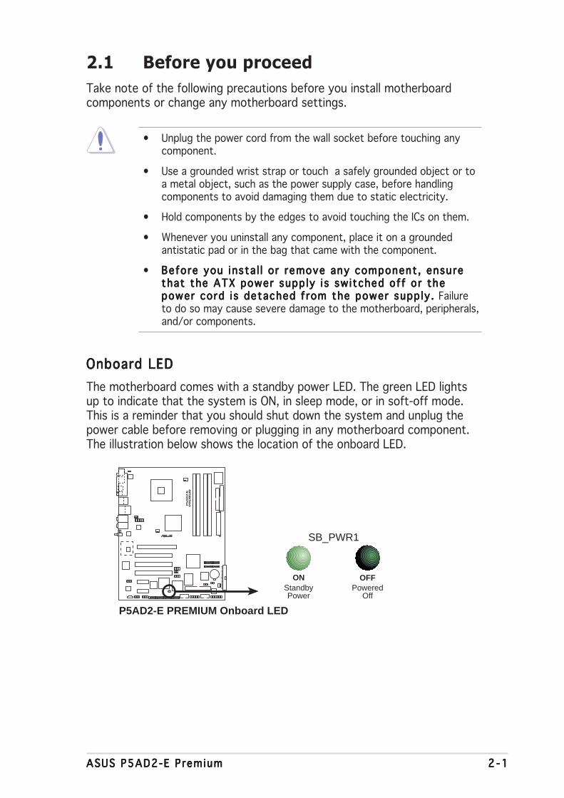
Onboard LEDOnboard LEDOnboard LEDOnboard LEDOnboard LED
The motherboard comes with a standby power LED. The green LED lightsup to indicate that the system is ON, in sleep mode, or in soft-off mode.This is a reminder that you should shut down the system and unplug thepower cable before removing or plugging in any motherboard component.The illustration below shows the location of the onboard LED.
2.1 Before you proceed
Take note of the following precautions before you install motherboardcomponents or change any motherboard settings.
• Unplug the power cord from the wall socket before touching anycomponent.
• Use a grounded wrist strap or touch a safely grounded object or toa metal object, such as the power supply case, before handlingcomponents to avoid damaging them due to static electricity.
• Hold components by the edges to avoid touching the ICs on them.
• Whenever you uninstall any component, place it on a groundedantistatic pad or in the bag that came with the component.
• Before you insta l l o r remove any component , ensureBefore you insta l l o r remove any component , ensureBefore you insta l l o r remove any component , ensureBefore you insta l l o r remove any component , ensureBefore you insta l l o r remove any component , ensurethat the ATX power supp ly i s sw itched of f or thethat the ATX power supp ly i s sw itched of f or thethat the ATX power supp ly i s sw itched of f or thethat the ATX power supp ly i s sw itched of f or thethat the ATX power supp ly i s sw itched of f or thepower cord i s detached f rom the power supp ly . power cord i s detached f rom the power supp ly . power cord i s detached f rom the power supp ly . power cord i s detached f rom the power supp ly . power cord i s detached f rom the power supp ly . Failureto do so may cause severe damage to the motherboard, peripherals,and/or components.
P5A
D2-E
PR
EM
IUM
®
P5AD2-E PREMIUM Onboard LED
SB_PWR1
ONStandbyPower
OFFPowered
Off
2 - 22 - 22 - 22 - 22 - 2 Chapter 2 : Hardware in format ionChapter 2 : Hardware in format ionChapter 2 : Hardware in format ionChapter 2 : Hardware in format ionChapter 2 : Hardware in format ion
P5A
D2-E
PR
EM
IUM
®
2.2 Motherboard overview
Before you install the motherboard, study the configuration of your chassisto ensure that the motherboard fits into it.
Make sure to unplug the power cord before installing or removing themotherboard. Failure to do so can cause you physical injury and damagemotherboard components.
Do not overtighten the screws! Doing so can damage the motherboard.
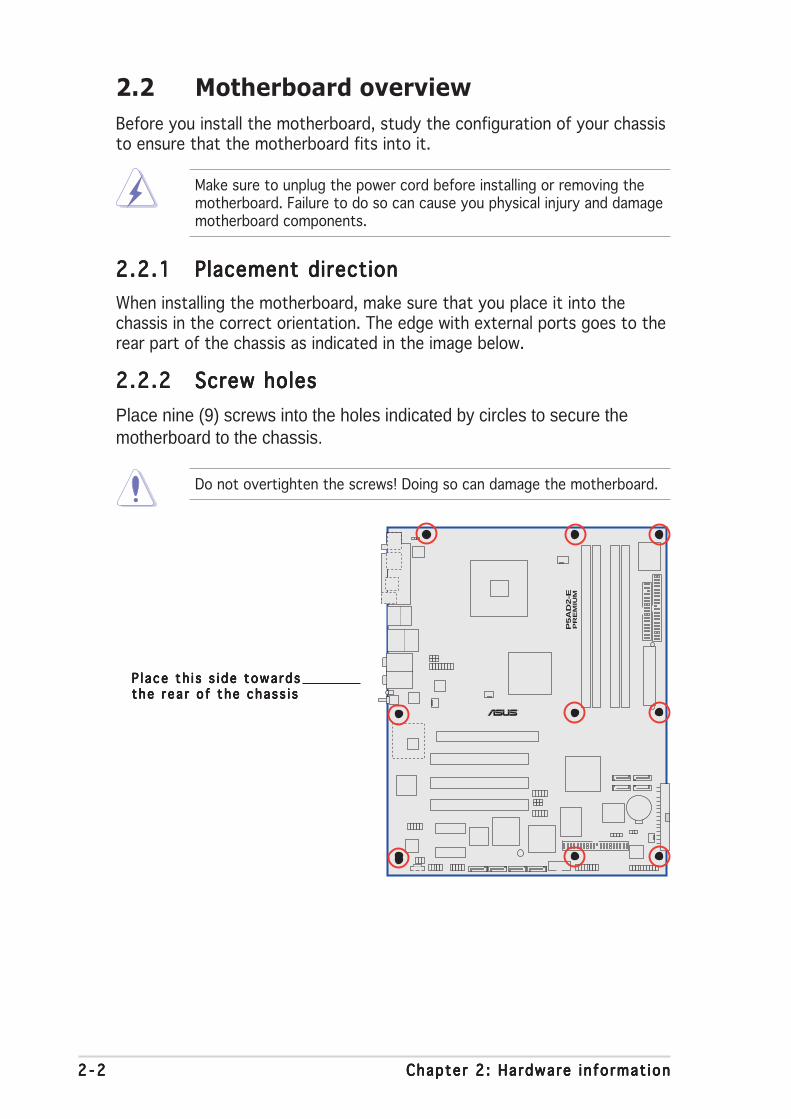
2.2.12.2.12.2.12.2.12.2.1 Placement directionPlacement directionPlacement directionPlacement directionPlacement direction
When installing the motherboard, make sure that you place it into thechassis in the correct orientation. The edge with external ports goes to therear part of the chassis as indicated in the image below.
2.2.22.2.22.2.22.2.22.2.2 Screw holesScrew holesScrew holesScrew holesScrew holes
Place nine (9) screws into the holes indicated by circles to secure themotherboard to the chassis.
P l ace th i s s i de towa rdsP l ace th i s s i de towa rdsP l ace th i s s i de towa rdsP l ace th i s s i de towa rdsP l ace th i s s i de towa rdsthe r ea r o f the chass i sthe r ea r o f the chass i sthe r ea r o f the chass i sthe r ea r o f the chass i sthe r ea r o f the chass i s
ASUS P5AD2-E PremiumASUS P5AD2-E PremiumASUS P5AD2-E PremiumASUS P5AD2-E PremiumASUS P5AD2-E Premium 2 - 32 - 32 - 32 - 32 - 3
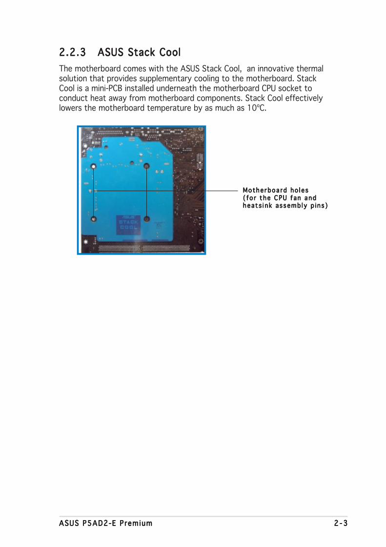
2.2.32.2.32.2.32.2.32.2.3 ASUS Stack CoolASUS Stack CoolASUS Stack CoolASUS Stack CoolASUS Stack Cool
The motherboard comes with the ASUS Stack Cool, an innovative thermalsolution that provides supplementary cooling to the motherboard. StackCool is a mini-PCB installed underneath the motherboard CPU socket toconduct heat away from motherboard components. Stack Cool effectivelylowers the motherboard temperature by as much as 10ºC.
Mothe rboa rd ho l e sMothe rboa rd ho l e sMothe rboa rd ho l e sMothe rboa rd ho l e sMothe rboa rd ho l e s( fo r t he CPU f an and( fo r t he CPU f an and( fo r t he CPU f an and( fo r t he CPU f an and( fo r t he CPU f an andheats i nk assemb ly p i n s )heats i nk assemb ly p i n s )heats i nk assemb ly p i n s )heats i nk assemb ly p i n s )heats i nk assemb ly p i n s )
2 - 42 - 42 - 42 - 42 - 4 Chapter 2 : Hardware in format ionChapter 2 : Hardware in format ionChapter 2 : Hardware in format ionChapter 2 : Hardware in format ionChapter 2 : Hardware in format ion
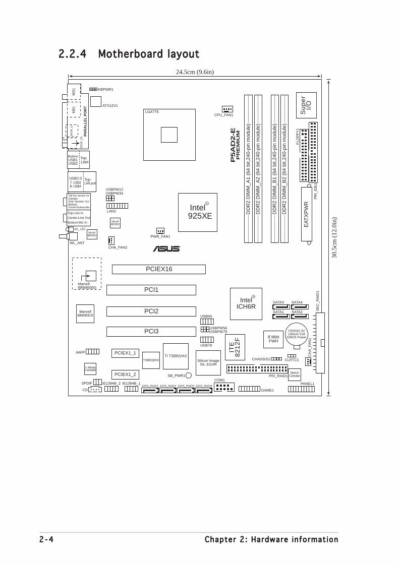
2.2.42.2.42.2.42.2.42.2.4 Motherboard layoutMotherboard layoutMotherboard layoutMotherboard layoutMotherboard layout
P5A
D2-E
PR
EM
IUM
®
CR2032 3VLithium Cell
CMOS Power
CD
Su
pe
rI/
O
8 MbitFWH
ATX12V1
FLO
PP
Y1
AAFP
DD
R2
DIM
M_A
1 (6
4 bi
t,240
-pin
mod
ule)
KBPWR1
SB_PWR1
USBPW34USBPW12
24.5cm (9.6in)
30.5
cm (
12.0
in)
Bottom:Mic In
Center:Line Out
Top:Line In
1394Top:USB1
USB2
Bottom:
PANEL1
CHASSIS1
GAME1
USB78
USB56
USBPW56USBPW78
COM1
SE
C_R
AID
1
PRI_RAID1
CLRTC1
SATA1C
HA
_FA
N1
SATA_RAID1 SATA_RAID2 SATA_RAID3
LAN2
PCIEX1_1
PCIEX1_2
PCI1
IE1394B_1IE1394B_2
Intel925X
IntelICH6R
PAR
AL
LE
L P
OR
T
MS
1K
B1
SP
DIF
_O
SP
DIF
_O2
DD
R2
DIM
M_A
2 (6
4 bi
t,240
-pin
mod
ule)
DD
R2
DIM
M_B
1 (6
4 bi
t,240
-pin
mod
ule)
DD
R2
DIM
M_B
2 (6
4 bi
t,240
-pin
mod
ule)
PWR_FAN1
CPU_FAN1
PR
I_ID
E1
SpeechController
TI TSB82AA2TSB81BA3
ITE
82
12
F
Marvell88W8310
C-MediaCMI9880
Marvell88W8000G
Silicon ImageSiL 3114R
WL_LED
WL_ANT
EAT
XP
WR
SATA3
SATA2
SATA4
PCIEX16
PCI2
PCI3
SATA_RAID4SPDIF
Marvell88E8053
Marvell88E8053
USB2.0T: USB3B: USB4
Top:LAN port
R
R
LGA775
CHA_FAN2
Below:Center/Subwoofer
Center:Side Speaker Out
Top:Rear Speaker Out
E
ASUS P5AD2-E PremiumASUS P5AD2-E PremiumASUS P5AD2-E PremiumASUS P5AD2-E PremiumASUS P5AD2-E Premium 2 - 52 - 52 - 52 - 52 - 5
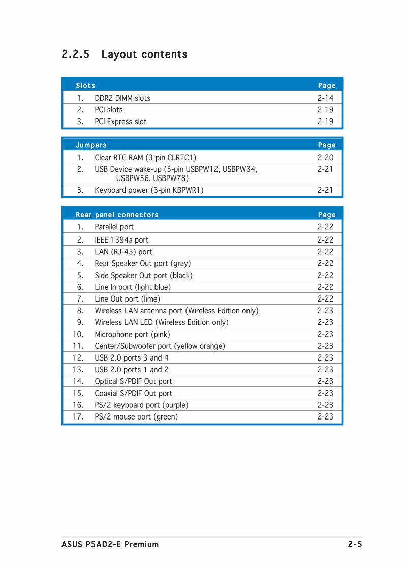
2.2.52.2.52.2.52.2.52.2.5 Layout contentsLayout contentsLayout contentsLayout contentsLayout contents
S l o t sS l o t sS l o t sS l o t sS l o t s P a g eP a g eP a g eP a g eP a g e
1. DDR2 DIMM slots 2-14
2. PCI slots 2-19
3. PCI Express slot 2-19
Jumpe r sJ umpe r sJ umpe r sJ umpe r sJ umpe r s P a g eP a g eP a g eP a g eP a g e
1. Clear RTC RAM (3-pin CLRTC1) 2-20
2. USB Device wake-up (3-pin USBPW12, USBPW34, 2-21USBPW56, USBPW78)
3. Keyboard power (3-pin KBPWR1) 2-21
Rea r pane l connec to r sRea r pane l connec to r sRea r pane l connec to r sRea r pane l connec to r sRea r pane l connec to r s P a g eP a g eP a g eP a g eP a g e
1. Parallel port 2-22
2. IEEE 1394a port 2-22
3. LAN (RJ-45) port 2-22
4. Rear Speaker Out port (gray) 2-22
5. Side Speaker Out port (black) 2-22
6. Line In port (light blue) 2-22
7. Line Out port (lime) 2-22
8. Wireless LAN antenna port (Wireless Edition only) 2-23
9. Wireless LAN LED (Wireless Edition only) 2-23
10. Microphone port (pink) 2-23
11. Center/Subwoofer port (yellow orange) 2-23
12. USB 2.0 ports 3 and 4 2-23
13. USB 2.0 ports 1 and 2 2-23
14. Optical S/PDIF Out port 2-23
15. Coaxial S/PDIF Out port 2-23
16. PS/2 keyboard port (purple) 2-23
17. PS/2 mouse port (green) 2-23
2 - 62 - 62 - 62 - 62 - 6 Chapter 2 : Hardware in format ionChapter 2 : Hardware in format ionChapter 2 : Hardware in format ionChapter 2 : Hardware in format ionChapter 2 : Hardware in format ion
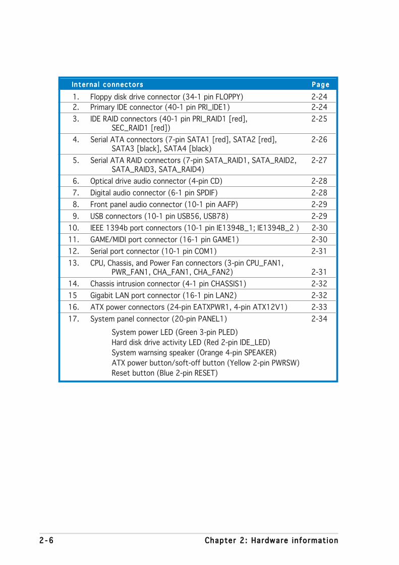
In te rna l connec to r sI n te rna l connec to r sI n te rna l connec to r sI n te rna l connec to r sI n te rna l connec to r s P a g eP a g eP a g eP a g eP a g e
1. Floppy disk drive connector (34-1 pin FLOPPY) 2-24
2. Primary IDE connector (40-1 pin PRI_IDE1) 2-24
3. IDE RAID connectors (40-1 pin PRI_RAID1 [red], 2-25SEC_RAID1 [red])
4. Serial ATA connectors (7-pin SATA1 [red], SATA2 [red], 2-26SATA3 [black], SATA4 [black)
5. Serial ATA RAID connectors (7-pin SATA_RAID1, SATA_RAID2, 2-27SATA_RAID3, SATA_RAID4)
6. Optical drive audio connector (4-pin CD) 2-28
7. Digital audio connector (6-1 pin SPDIF) 2-28
8. Front panel audio connector (10-1 pin AAFP) 2-29
9. USB connectors (10-1 pin USB56, USB78) 2-29
10. IEEE 1394b port connectors (10-1 pin IE1394B_1; IE1394B_2 ) 2-30
11. GAME/MIDI port connector (16-1 pin GAME1) 2-30
12. Serial port connector (10-1 pin COM1) 2-31
13. CPU, Chassis, and Power Fan connectors (3-pin CPU_FAN1,PWR_FAN1, CHA_FAN1, CHA_FAN2) 2-31
14. Chassis intrusion connector (4-1 pin CHASSIS1) 2-32
15 Gigabit LAN port connector (16-1 pin LAN2) 2-32
16. ATX power connectors (24-pin EATXPWR1, 4-pin ATX12V1) 2-33
17. System panel connector (20-pin PANEL1) 2-34
System power LED (Green 3-pin PLED)
Hard disk drive activity LED (Red 2-pin IDE_LED)
System warnsing speaker (Orange 4-pin SPEAKER)
ATX power button/soft-off button (Yellow 2-pin PWRSW)
Reset button (Blue 2-pin RESET)
ASUS P5AD2-E PremiumASUS P5AD2-E PremiumASUS P5AD2-E PremiumASUS P5AD2-E PremiumASUS P5AD2-E Premium 2 - 72 - 72 - 72 - 72 - 7
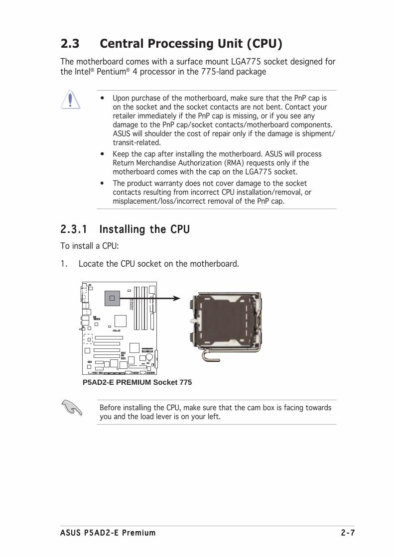
2.3.12.3.12.3.12.3.12.3.1 Installing the CPUInstalling the CPUInstalling the CPUInstalling the CPUInstalling the CPU
To install a CPU:
1. Locate the CPU socket on the motherboard.
2.3 Central Processing Unit (CPU)
The motherboard comes with a surface mount LGA775 socket designed forthe Intel® Pentium® 4 processor in the 775-land package
Before installing the CPU, make sure that the cam box is facing towardsyou and the load lever is on your left.
• Upon purchase of the motherboard, make sure that the PnP cap ison the socket and the socket contacts are not bent. Contact yourretailer immediately if the PnP cap is missing, or if you see anydamage to the PnP cap/socket contacts/motherboard components.ASUS will shoulder the cost of repair only if the damage is shipment/transit-related.
• Keep the cap after installing the motherboard. ASUS will processReturn Merchandise Authorization (RMA) requests only if themotherboard comes with the cap on the LGA775 socket.
• The product warranty does not cover damage to the socketcontacts resulting from incorrect CPU installation/removal, ormisplacement/loss/incorrect removal of the PnP cap.
P5A
D2-E
PR
EM
IUM
®
P5AD2-E PREMIUM Socket 775

2 - 82 - 82 - 82 - 82 - 8 Chapter 2 : Hardware in format ionChapter 2 : Hardware in format ionChapter 2 : Hardware in format ionChapter 2 : Hardware in format ionChapter 2 : Hardware in format ion
3. Lift the load lever in thedirection of the arrow to a 135ºangle.
4. Lift the load plate with yourthumb and forefinger to a 100ºangle (A), then push the PnP capfrom the load plate window toremove (B).
5. Position the CPU overthe socket, making surethat the gold triangle ison the bottom-leftcorner of the socket.The socket alignmentkey should fit into theCPU notch.
A l i gnment keyA l i gnment keyA l i gnment keyA l i gnment keyA l i gnment key
Go ld t r i ang l e ma rkGo ld t r i ang l e ma rkGo ld t r i ang l e ma rkGo ld t r i ang l e ma rkGo ld t r i ang l e ma rk
Load p l a t eLoad p l a t eLoad p l a t eLoad p l a t eLoad p l a t e
A
B
2. Press the load lever with your thumb (A), then move it to the left (B)until it is released from the retention tab.
Re ten t i on t abRe ten t i on t abRe ten t i on t abRe ten t i on t abRe ten t i on t ab
Load l e ve rLoad l e ve rLoad l e ve rLoad l e ve rLoad l e ve r
Th i s s i de o f t heTh i s s i de o f t heTh i s s i de o f t heTh i s s i de o f t heTh i s s i de o f t hesocke t box shou l dsocke t box shou l dsocke t box shou l dsocke t box shou l dsocke t box shou l df a ce you .f a ce you .f a ce you .f a ce you .f a ce you .
P n P c a pP n P c a pP n P c a pP n P c a pP n P c a pA
B
To prevent damage to the socket pins, do not remove the PnP capunless you are installing a CPU.
ASUS P5AD2-E PremiumASUS P5AD2-E PremiumASUS P5AD2-E PremiumASUS P5AD2-E PremiumASUS P5AD2-E Premium 2 - 92 - 92 - 92 - 92 - 9
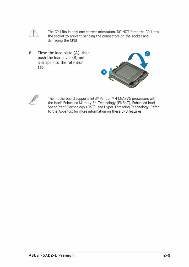
The CPU fits in only one correct orientation. DO NOT force the CPU intothe socket to prevent bending the connectors on the socket anddamaging the CPU!
6. Close the load plate (A), thenpush the load lever (B) untilit snaps into the retentiontab.
A
B
The motherboard supports Intel® Pentium® 4 LGA775 processors withthe Intel® Enhanced Memory 64 Technology (EM64T), Enhanced IntelSpeedStep® Technology (EIST), and Hyper-Threading Technology. Referto the Appendix for more information on these CPU features.
2 -102 -102 -102 -102 -10 Chapter 2 : Hardware in format ionChapter 2 : Hardware in format ionChapter 2 : Hardware in format ionChapter 2 : Hardware in format ionChapter 2 : Hardware in format ion
Fa s t ene rF a s t ene rF a s t ene rF a s t ene rF a s t ene r
Mothe rboa rd ho l eMothe rboa rd ho l eMothe rboa rd ho l eMothe rboa rd ho l eMothe rboa rd ho l e
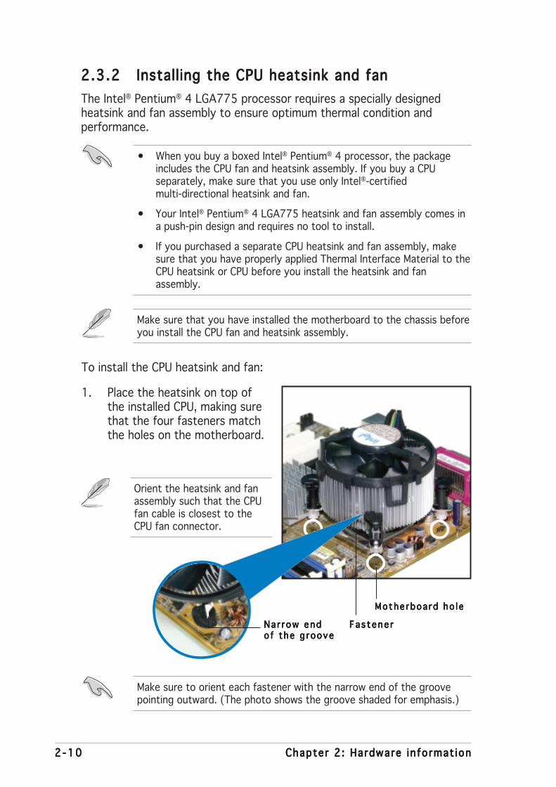
2.3.22.3.22.3.22.3.22.3.2 Installing the CPU heatsink and fanInstalling the CPU heatsink and fanInstalling the CPU heatsink and fanInstalling the CPU heatsink and fanInstalling the CPU heatsink and fan
The Intel® Pentium® 4 LGA775 processor requires a specially designedheatsink and fan assembly to ensure optimum thermal condition andperformance.
To install the CPU heatsink and fan:
1. Place the heatsink on top ofthe installed CPU, making surethat the four fasteners matchthe holes on the motherboard.
Na r r ow endNa r r ow endNa r r ow endNa r r ow endNa r r ow endo f t he g rooveo f t he g rooveo f t he g rooveo f t he g rooveo f t he g roove
• When you buy a boxed Intel® Pentium® 4 processor, the packageincludes the CPU fan and heatsink assembly. If you buy a CPUseparately, make sure that you use only Intel®-certifiedmulti-directional heatsink and fan.
• Your Intel® Pentium® 4 LGA775 heatsink and fan assembly comes ina push-pin design and requires no tool to install.
• If you purchased a separate CPU heatsink and fan assembly, makesure that you have properly applied Thermal Interface Material to theCPU heatsink or CPU before you install the heatsink and fanassembly.
Make sure that you have installed the motherboard to the chassis beforeyou install the CPU fan and heatsink assembly.
Make sure to orient each fastener with the narrow end of the groovepointing outward. (The photo shows the groove shaded for emphasis.)
Orient the heatsink and fanassembly such that the CPUfan cable is closest to theCPU fan connector.

ASUS P5AD2-E PremiumASUS P5AD2-E PremiumASUS P5AD2-E PremiumASUS P5AD2-E PremiumASUS P5AD2-E Premium 2 -112 -112 -112 -112 -11
3. Connect the CPU fan cable to the connector on the motherboardlabeled CPU_FAN1.
2. Push down two fasteners at atime in a diagonal sequence tosecure the heatsink and fanassembly in place.
B
B
AA
A
A B
B
Do not forget to connect the CPU fan connector! Hardware monitoringerrors can occur if you fail to plug this connector.
P5A
D2-E
PR
EM
IUM
CPU_FAN1
GN
DC
PU
FA
N P
WR
CP
U F
AN
INC
PU
FA
N P
WM

2 -122 -122 -122 -122 -12 Chapter 2 : Hardware in format ionChapter 2 : Hardware in format ionChapter 2 : Hardware in format ionChapter 2 : Hardware in format ionChapter 2 : Hardware in format ion
2.3.32.3.32.3.32.3.32.3.3 Uninstalling the CPU heatsink and fanUninstalling the CPU heatsink and fanUninstalling the CPU heatsink and fanUninstalling the CPU heatsink and fanUninstalling the CPU heatsink and fan
To uninstall the CPU heatsink and fan:
1. Disconnect the CPU fan cablefrom the connector on themotherboard.
2. Rotate each fastenercounterclockwise.
3. Pull up two fasteners at a timein a diagonal sequence todisengage the heatsink and fanassembly from themotherboard.
B
B
AA
A
A B
B
4. Carefully remove the heatsinkand fan assembly from themotherboard.
ASUS P5AD2-E PremiumASUS P5AD2-E PremiumASUS P5AD2-E PremiumASUS P5AD2-E PremiumASUS P5AD2-E Premium 2 -132 -132 -132 -132 -13
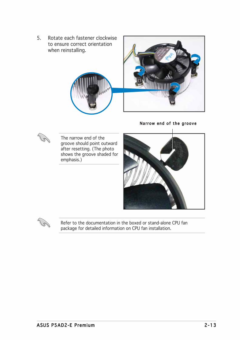
5. Rotate each fastener clockwiseto ensure correct orientationwhen reinstalling.
The narrow end of thegroove should point outwardafter resetting. (The photoshows the groove shaded foremphasis.)
Na r row end o f the g rooveNa r row end o f the g rooveNa r row end o f the g rooveNa r row end o f the g rooveNa r row end o f the g roove
Refer to the documentation in the boxed or stand-alone CPU fanpackage for detailed information on CPU fan installation.
2 -142 -142 -142 -142 -14 Chapter 2 : Hardware in format ionChapter 2 : Hardware in format ionChapter 2 : Hardware in format ionChapter 2 : Hardware in format ionChapter 2 : Hardware in format ion
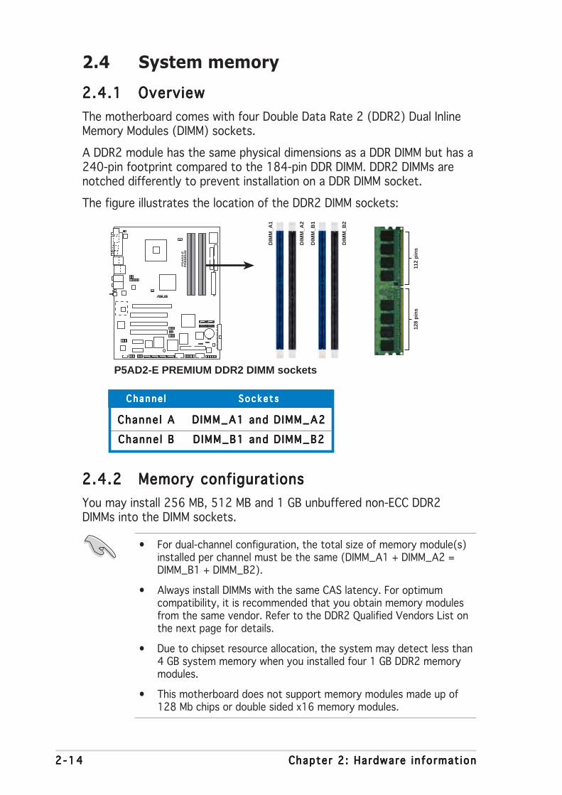
2.4 System memory
2.4.12.4.12.4.12.4.12.4.1 OverviewOverviewOverviewOverviewOverview
The motherboard comes with four Double Data Rate 2 (DDR2) Dual InlineMemory Modules (DIMM) sockets.
A DDR2 module has the same physical dimensions as a DDR DIMM but has a240-pin footprint compared to the 184-pin DDR DIMM. DDR2 DIMMs arenotched differently to prevent installation on a DDR DIMM socket.
The figure illustrates the location of the DDR2 DIMM sockets:
2.4.22.4.22.4.22.4.22.4.2 Memory configurationsMemory configurationsMemory configurationsMemory configurationsMemory configurations
You may install 256 MB, 512 MB and 1 GB unbuffered non-ECC DDR2DIMMs into the DIMM sockets.
• For dual-channel configuration, the total size of memory module(s)installed per channel must be the same (DIMM_A1 + DIMM_A2 =DIMM_B1 + DIMM_B2).
• Always install DIMMs with the same CAS latency. For optimumcompatibility, it is recommended that you obtain memory modulesfrom the same vendor. Refer to the DDR2 Qualified Vendors List onthe next page for details.
• Due to chipset resource allocation, the system may detect less than4 GB system memory when you installed four 1 GB DDR2 memorymodules.
• This motherboard does not support memory modules made up of128 Mb chips or double sided x16 memory modules.
Channe lChanne lChanne lChanne lChanne l S o c k e t sS o c k e t sS o c k e t sS o c k e t sS o c k e t s
Channe l AChanne l AChanne l AChanne l AChanne l A D IMM_A1 and D IMM_A2DIMM_A1 and D IMM_A2DIMM_A1 and D IMM_A2DIMM_A1 and D IMM_A2DIMM_A1 and D IMM_A2
Channe l BChanne l BChanne l BChanne l BChanne l B D IMM_B1 and D IMM_B2DIMM_B1 and D IMM_B2DIMM_B1 and D IMM_B2DIMM_B1 and D IMM_B2DIMM_B1 and D IMM_B2
P5A
D2-E
PR
EM
IUM
®
P5AD2-E PREMIUM DDR2 DIMM sockets
DIM
M_A
1
DIM
M_A
2
DIM
M_B
1
DIM
M_B
2
112
pin
s12
8 p
ins
ASUS P5AD2-E PremiumASUS P5AD2-E PremiumASUS P5AD2-E PremiumASUS P5AD2-E PremiumASUS P5AD2-E Premium 2 -152 -152 -152 -152 -15
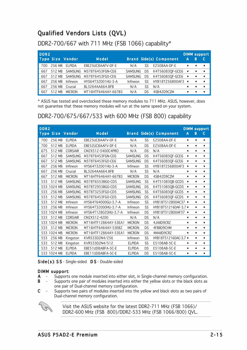
Qualified Vendors Lists (QVL)Qualified Vendors Lists (QVL)Qualified Vendors Lists (QVL)Qualified Vendors Lists (QVL)Qualified Vendors Lists (QVL)
DDR2-700/667 with 711 MHz (FSB 1066) capability*
700 256 MB ELPIDA EBE25UC8AAFV-DF-E N/A SS E2508AA-DF-E • • •
667 512 MB SAMSUNG M378T6453FGN-CE6 SAMSUNG DS K4T56083QF-GCE6 • • •
667 512 MB SAMSUNG M378T6453FG0-CE6 SAMSUNG DS K4T56083QF-GCE6 • • •
667 256 MB Infineon HYS64T32001HU-3-A Infineon SS HYB18T256800AF3 • • •
667 256 MB Crucial BL3264AA664.8FB N/A SS N/A • • •
667 512 MB MICRON MT16HTF6464AY-667B3 N/A DS 4SB42D9CZM • • •
D D R 2D D R 2D D R 2D D R 2D D R 2
T y p eT y p eT y p eT y p eT y p e S i z eS i z eS i z eS i z eS i z e V e n d o rV e n d o rV e n d o rV e n d o rV e n d o r M o d e lM o d e lM o d e lM o d e lM o d e l B r a n dB r a n dB r a n dB r a n dB r a n d Side(s)Side(s)Side(s)Side(s)Side(s) C o m p o n e n tC o m p o n e n tC o m p o n e n tC o m p o n e n tC o m p o n e n t AAAAA BBBBB CCCCC
DIMM supportD IMM supportD IMM supportD IMM supportD IMM support
S i d e ( s )S i d e ( s )S i d e ( s )S i d e ( s )S i d e ( s ): S SS SS SS SS S - Single-sided D SD SD SD SD S - Double-sided
D IMM suppo r tD IMM suppo r tD IMM suppo r tD IMM suppo r tD IMM suppo r t:AAAAA - Supports one module inserted into either slot, in Single-channel memory configuration.BBBBB - Supports one pair of modules inserted into either the yellow slots or the black slots as
one pair of Dual-channel memory configuration.CCCCC - Supports two pairs of modules inserted into the yellow and black slots as two pairs of
Dual-channel memory configuration.
Visit the ASUS website for the latest DDR2-711 MHz (FSB 1066)/DDR2-600 MHz (FSB 800)/DDR2-533 MHz (FSB 1066/800) QVL.
* ASUS has tested and overclocked these memory modules to 711 MHz. ASUS, however, doesnot guarantee that these memory modules will run at the same speed on your system.
700 256 MB ELPIDA EBE25UC8AAFV-DF-E N/A SS E2508AA-DF-E • • •
700 512 MB ELPIDA EBE52UC8AAFV-DF-E N/A DS E2508AA-DF-E • • •
675 512 MB CORSAIR CM2X512-5400C4PRO N/A DS N/A • • •
667 512 MB SAMSUNG M378T6453FGN-CE6 SAMSUNG DS K4T56083QF-GCE6 • • •
667 512 MB SAMSUNG M378T6453FG0-CE6 SAMSUNG DS K4T56083QF-GCE6 • • •
667 256 MB Infineon HYS64T32001HU-3-A Infineon SS HYB18T256800AF3 • • •
667 256 MB Crucial BL3264AA664.8FB N/A SS N/A • • •
667 512 MB MICRON MT16HTF6464AY-667B3 MICRON DS 4SB42D9CZM • • •
533 512 MB SAMSUNG M378T6553BG0-CD5 SAMSUNG SS K4T51083QB-GCD5 • • •
533 1024 MB SAMSUNG M378T2953BG0-CD5 SAMSUNG DS K4T51083QB-GCD5 • • •
533 256 MB SAMSUNG M378T3253FG0-CD5 SAMSUNG SS K4T56083QF-GCD5 • • •
533 512 MB SAMSUNG M378T6453FG0-CD5 SAMSUNG DS K4T56083QF-GCD5 • • •
533 512 MB Infineon HYS64T64000GU-3.7-A Infineon SS HYB18T512800AC37 • • •
533 256 MB Infineon HYS64T32000HU-3.7-A Infineon SS HYB18T512160AF-3.7• • •
533 1024 MB Infineon HYS64T128020HU-3.7-A Infineon DS HYB18T512800AF37 • • •
533 512 MB CORSAIR CM2X512-4200 N/A DS N/A • • •
533 1024 MB MICRON MT16HTF12864AY-53EA1 MICRON DS 4JAIID9CRZ • • •
533 512 MB MICRON MT16HTF6464AY-53EB2 MICRON DS 4FBIID9CHM • • •
533 1024 MB MICRON MT16HTF12864AY-53EA1 MICRON DS 4MAIID9CRZ • • •
533 256 MB Kingston KVR533D2N4/256 Infineon SS HYB18T512160AC-3.7 • • •
533 512 MB Kingston KVR533D2N4/512 ELPIDA SS E5108AB-5C-E • • •
533 512 MB ELPIDA EBE51UD8ABFA-5C-E ELPIDA DS E5108AB-5C-E • • •
533 1024 MB ELPIDA EBE11UD8ABFA-5C-E ELPIDA DS E5108AB-5C-E • • •
D D R 2D D R 2D D R 2D D R 2D D R 2
T y p eT y p eT y p eT y p eT y p e S i z eS i z eS i z eS i z eS i z e V e n d o rV e n d o rV e n d o rV e n d o rV e n d o r M o d e lM o d e lM o d e lM o d e lM o d e l B r a n dB r a n dB r a n dB r a n dB r a n d Side(s)Side(s)Side(s)Side(s)Side(s) C o m p o n e n tC o m p o n e n tC o m p o n e n tC o m p o n e n tC o m p o n e n t AAAAA BBBBB CCCCC
DIMM supportD IMM supportD IMM supportD IMM supportD IMM support
DDR2-700/675/667/533 with 600 MHz (FSB 800) capability

2 -162 -162 -162 -162 -16 Chapter 2 : Hardware in format ionChapter 2 : Hardware in format ionChapter 2 : Hardware in format ionChapter 2 : Hardware in format ionChapter 2 : Hardware in format ion
256 MB ELPIDA EBE25UC8AAFV-DF-E N/A SS E2508AA-DF-E • • •
512 MB SAMSUNG M378T6553BG0-CD5 SAMSUNG SS K4T51083QB-GCD5 • • •
1024 MB SAMSUNG M378T2953BG0-CD5 SAMSUNG DS K4T51083QB-GCD5 • • •
256 MB SAMSUNG M378T3253FG0-CD5 SAMSUNG SS K4T56083QF-GCD5 • • •
512 MB SAMSUNG M378T6453FG0-CD5 SAMSUNG DS K4T56083QF-GCD5 • • •
512 MB Infineon HYS64T64000GU-3.7-A Infineon SS HYB18T512800AC37 • • •
512 MB CORSAIR CM2X512-4200 N/A DS N/A • • •
512 MB MICRON MT16HTF6464AG-53EB2 MICRON DS 4FBIID9BQM • • •
1024 MB MICRON MT16HTF12864AY-53EA1 MICRON DS 4JAIID9CRZ • • •
256 MB MICRON MT8HTF3264AY-53EB3 MICRON SS 4FBIID9CHM • • •
512 MB MICRON MT16HTF6464AY-53EB2 MICRON DS 4FBIID9CHM • • •
1024 MB MICRON MT16HTF12864AY-53EA1 MICRON DS 4MAIID9CRZ • • •
1024 MB Kingston KVR533D2N4/1G ELPIDA DS E5108AB-5C-E • • •
512 MB Kingston KVR533D2N4/512 ELPIDA SS E5108AB-5C-E • • •
512 MB Hynix HYMP564U648-C4 N/A SS HY5PS12821F-C4 • • •
1024 MB Hynix HYMP512U648-C4 N/A DS HY5PS12821F-C4 • • •
1024 MB Hynix HYMP512U648-C4 N/A DS HY5PS12821FP-C4 • • •
512 MB ELPIDA EBE51UD8ABFA-5C ELPIDA DS E5108AB-5C-E • • •
512 MB ELPIDA EBE51UD8ABFA-5C-E ELPIDA DS E5108AB-5C-E • • •
1024 MB ELPIDA EBE11UD8ABFA-5C-E ELPIDA DS E5108AB-5C-E • • •
512 MB KINGMAX KLBC28K-38MP4 N/A DS 4IBIID9BQM • • •
256 MB KINGMAX KLBB68K-38MP4 N/A SS 4KBIID9BQM • • •
1024 MB KINGMAX KLBD48K-A8MP4 MICRON DS 4MAIID9CRZ • • •
512 MB KINGMAX KLBC28K-A8EP4 ELPIDA SS E5108AB-5C-E • •
512 MB TwinMOS 8D-22JB5-K2T SAMSUNG SS K4T51083QB-GCD5 • • •
512 MB Apacer 78.91066.460 SAMSUNG SS K4T51083QB-GCD5 • • •
1024 MB Apacer 78.01066.460 SAMSUNG DS K4T51083QB-GCD5 • • •
1024 MB Apacer 78.01066.110 Infineon DS HYB18T512800AC37 • • •
256 MB BRAIN POWERBS212-1-256M-MIC-533 N/A SS 4CBIIZ9BQT • • •
512 MB BRAIN POWERBS213-1-512M-MIC-533 N/A DS 4CBIIZ9BQT • • •
512 MB Geil GX2 1GB4200DC N/A SS N/A • • •
256 MB NANYA NT256T64UH4A0F-37B NANYA SS NT5TU32M16AF-37B • • •
512 MB NANYA NT512T64U88A0F-37B NANYA SS NT5TU64M8AF-37B • • •
512 MB elixir M2U51264TU88A0F-37B N/A SS N2TU51280AF-3C • • •
512 MB A-DATA M2OAD2G3H3110A1B0E A-DATA SS AD29608A8A-375D • • •
256 MB Ballistix BL3264AA53V.8FB N/A SS N/A • • •
512 MB Ballistix BL6464AA53V.16FB N/A DS N/A • • •
S i z eS i z eS i z eS i z eS i z e V e n d o rV e n d o rV e n d o rV e n d o rV e n d o r M o d e lM o d e lM o d e lM o d e lM o d e l B r a n dB r a n dB r a n dB r a n dB r a n d Side(s)Side(s)Side(s)Side(s)Side(s) C o m p o n e n t C o m p o n e n t C o m p o n e n t C o m p o n e n t C o m p o n e n t AAAAA BBBBB CCCCC
DIMM supportDIMM supportDIMM supportDIMM supportDIMM support
DDR2-533
ASUS P5AD2-E PremiumASUS P5AD2-E PremiumASUS P5AD2-E PremiumASUS P5AD2-E PremiumASUS P5AD2-E Premium 2 -172 -172 -172 -172 -17
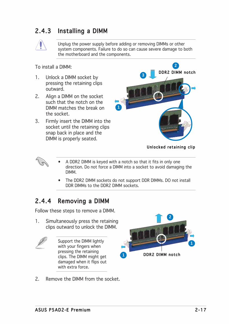
2.4.32.4.32.4.32.4.32.4.3 Installing a DIMMInstalling a DIMMInstalling a DIMMInstalling a DIMMInstalling a DIMM
Unplug the power supply before adding or removing DIMMs or othersystem components. Failure to do so can cause severe damage to boththe motherboard and the components.
To install a DIMM:
1. Unlock a DIMM socket bypressing the retaining clipsoutward.
2. Align a DIMM on the socketsuch that the notch on theDIMM matches the break onthe socket.
3. Firmly insert the DIMM into thesocket until the retaining clipssnap back in place and theDIMM is properly seated.
2.4.42.4.42.4.42.4.42.4.4 Removing a DIMMRemoving a DIMMRemoving a DIMMRemoving a DIMMRemoving a DIMM
Follow these steps to remove a DIMM.
1. Simultaneously press the retainingclips outward to unlock the DIMM.
2. Remove the DIMM from the socket.
• A DDR2 DIMM is keyed with a notch so that it fits in only onedirection. Do not force a DIMM into a socket to avoid damaging theDIMM.
• The DDR2 DIMM sockets do not support DDR DIMMs. DO not installDDR DIMMs to the DDR2 DIMM sockets.
Un locked re ta i n i ng c l i pUn locked re ta i n i ng c l i pUn locked re ta i n i ng c l i pUn locked re ta i n i ng c l i pUn locked re ta i n i ng c l i p
DDR2 D IMM no tchDDR2 D IMM no tchDDR2 D IMM no tchDDR2 D IMM no tchDDR2 D IMM no tch
Support the DIMM lightlywith your fingers whenpressing the retainingclips. The DIMM might getdamaged when it flips outwith extra force.
DDR2 D IMM no tchDDR2 D IMM no tchDDR2 D IMM no tchDDR2 D IMM no tchDDR2 D IMM no tch
1
2
3
1
2
1

2 -182 -182 -182 -182 -18 Chapter 2 : Hardware in format ionChapter 2 : Hardware in format ionChapter 2 : Hardware in format ionChapter 2 : Hardware in format ionChapter 2 : Hardware in format ion
2.5 Expansion slots
In the future, you may need to install expansion cards. The followingsub-sections describe the slots and the expansion cards that they support.
2.5.12.5.12.5.12.5.12.5.1 Installing an expansion cardInstalling an expansion cardInstalling an expansion cardInstalling an expansion cardInstalling an expansion card
To install an expansion card:
1. Before installing the expansion card, read the documentation thatcame with it and make the necessary hardware settings for the card.
2. Remove the system unit cover (if your motherboard is alreadyinstalled in a chassis).
3. Remove the bracket opposite the slot that you intend to use. Keepthe screw for later use.
4. Align the card connector with the slot and press firmly until the card iscompletely seated on the slot.
5. Secure the card to the chassis with the screw you removed earlier.
6. Replace the system cover.
2.5.22.5.22.5.22.5.22.5.2 Configuring an expansion cardConfiguring an expansion cardConfiguring an expansion cardConfiguring an expansion cardConfiguring an expansion card
After installing the expansion card, configure the it by adjusting thesoftware settings.
1. Turn on the system and change the necessary BIOS settings, if any.See Chapter 4 for information on BIOS setup.
2. Assign an IRQ to the card. Refer to the tables on the next page.
3. Install the software drivers for the expansion card.
Make sure to unplug the power cord before adding or removingexpansion cards. Failure to do so may cause you physical injury anddamage motherboard components.
When using PCI cards on shared slots, ensure that the drivers support“Share IRQ” or that the cards do not need IRQ assignments. Otherwise,conflicts will arise between the two PCI groups, making the systemunstable and the card inoperable. Refer to the table on the next page fordetails.

ASUS P5AD2-E PremiumASUS P5AD2-E PremiumASUS P5AD2-E PremiumASUS P5AD2-E PremiumASUS P5AD2-E Premium 2 -192 -192 -192 -192 -19
2.5.32.5.32.5.32.5.32.5.3 Interrupt assignmentsInterrupt assignmentsInterrupt assignmentsInterrupt assignmentsInterrupt assignments
Standard interrupt assignmentsStandard interrupt assignmentsStandard interrupt assignmentsStandard interrupt assignmentsStandard interrupt assignments
I R QI R QI R QI R QI R Q P r i o r i t yP r i o r i t yP r i o r i t yP r i o r i t yP r i o r i t y S tanda rd Func t i onStanda rd Func t i onStanda rd Func t i onStanda rd Func t i onStanda rd Func t i on
0 1 System Timer
1 2 Keyboard Controller
2 — Re-direct to IRQ#9
3 11 Communications Port (COM2)*
4 12 Communications Port (COM1)*
5 13 IRQ holder for PCI steering*
6 14 Floppy Disk Controller
7 15 Printer Port (LPT1)*
8 3 System CMOS/Real Time Clock
9 4 IRQ holder for PCI steering*
10 5 IRQ holder for PCI steering*
11 6 IRQ holder for PCI steering*
12 7 PS/2 Compatible Mouse Port*
13 8 Numeric Data Processor
14 9 Primary IDE Channel
15 10 Secondary IDE Channel
* These IRQs are usually available for ISA or PCI devices.
IRQ assignments for this motherboardIRQ assignments for this motherboardIRQ assignments for this motherboardIRQ assignments for this motherboardIRQ assignments for this motherboard
AAAAA BBBBB CCCCC DDDDD EEEEE FFFFF GGGGG HHHHH
PCI slot 1 — — — — — — shared —
PCI slot 2 — — — — — shared — —
PCI slot 3 — shared — — — — — —
PCI E x16 slot shared — — — — — — —
PCI E x1 slot 1 shared — — — — — — —
PCI E x1 slot 2 — — — shared — — — —
Onboard USB controller 1 shared — — — — — — —
Onboard USB controller 2 — shared — — — — — —
Onboard USB controller 3 — — shared — — — — —
Onboard USB controller 4 — — — shared — — — —
Onboard USB 2.0 controller shared — — — — — — —
Onboard IDE port shared — — — — — — —
Onboard SATA port — shared — — — — — —
Onboard Azalia audio shared — — — — — — —
Onboard LAN1 — shared — — — — — —
Onboard LAN2 — — shared — — — — —
Onboard wireless LAN — — — — used — — —
Onboard PCI SATA RAID (SI) — — — — — — shared —
Onboard PCI IDE RAID (ITE) — — — — — — — used
Onboard 1394b controller — — — — — shared — —

2 -202 -202 -202 -202 -20 Chapter 2 : Hardware in format ionChapter 2 : Hardware in format ionChapter 2 : Hardware in format ionChapter 2 : Hardware in format ionChapter 2 : Hardware in format ion
2.5.42.5.42.5.42.5.42.5.4 PCI slotsPCI slotsPCI slotsPCI slotsPCI slots
The PCI slots support cards such as aLAN card, SCSI card, USB card, andother cards that comply with PCIspecifications. The figure shows aLAN card installed on a PCI slot.
2.5.52.5.52.5.52.5.52.5.5 PCI Express x16 slotPCI Express x16 slotPCI Express x16 slotPCI Express x16 slotPCI Express x16 slot
This motherboard supports PCIExpress x16 graphic cards thatcomply with the PCI Expressspecifications. The following figureshows a graphics card installed onthe PCI Express x16 slot.
2.5.62.5.62.5.62.5.62.5.6 PCI Express x1 slotPCI Express x1 slotPCI Express x1 slotPCI Express x1 slotPCI Express x1 slot
This motherboard supports PCIExpress x1 network cards, SCSI cardsand other cards that comply with thePCI Express specifications. Thefollowing figure shows a network cardinstalled on the PCI Express x1 slot.

ASUS P5AD2-E PremiumASUS P5AD2-E PremiumASUS P5AD2-E PremiumASUS P5AD2-E PremiumASUS P5AD2-E Premium 2 -212 -212 -212 -212 -21
2.6 Jumpers
1 .1 .1 .1 .1 . C lear RTC RAM (CLRTC)Clear RTC RAM (CLRTC)Clear RTC RAM (CLRTC)Clear RTC RAM (CLRTC)Clear RTC RAM (CLRTC)
This jumper allows you to clear the Real Time Clock (RTC) RAM inCMOS. You can clear the CMOS memory of date, time, and systemsetup parameters by erasing the CMOS RTC RAM data. The onboardbutton cell battery powers the RAM data in CMOS, which includesystem setup information such as system passwords.
To erase the RTC RAM:
1. Turn OFF the computer and unplug the power cord.
2. Remove the onboard battery.
3. Move the jumper cap from pins 1-2 (default) to pins 2-3. Keep thecap on pins 2-3 for about 5~10 seconds, then move the cap backto pins 1-2.
4. Re-install the battery.
5. Plug the power cord and turn ON the computer.
6. Hold down the <Del> key during the boot process and enter BIOSsetup to re-enter data.
Except when clearing the RTC RAM, never remove the cap on CLRTCjumper default position. Removing the cap will cause system boot failure!
1 2 2 3
P5A
D2-E
PR
EM
IUM
®
P5AD2-E PREMIUM Clear RTC RAM
CLRTC1
Normal Clear CMOS(Default)
You do not need to clear the RTC when the system hangs due tooverclocking. For system failure due to overclocking, use the C.P.R. (CPUParameter Recall) feature. Shut down and reboot the system so the BIOScan automatically reset parameter settings to default values.

2 -222 -222 -222 -222 -22 Chapter 2 : Hardware in format ionChapter 2 : Hardware in format ionChapter 2 : Hardware in format ionChapter 2 : Hardware in format ionChapter 2 : Hardware in format ion
3 .3 .3 .3 .3 . Keyboard power (3-pin KBPWR1)Keyboard power (3-pin KBPWR1)Keyboard power (3-pin KBPWR1)Keyboard power (3-pin KBPWR1)Keyboard power (3-pin KBPWR1)
This jumper allows you to enable or disable the keyboard wake-upfeature. Set this jumper to pins 2-3 (+5VSB) to wake up the computerwhen you press a key on the keyboard (the default is the Space Bar).This feature requires an ATX power supply that can supply at least 1Aon the +5VSB lead, and a corresponding setting in the BIOS.
2 .2 .2 .2 .2 . USB device wake-up jumpers (3-pin USBPW12, USBPW34,USB device wake-up jumpers (3-pin USBPW12, USBPW34,USB device wake-up jumpers (3-pin USBPW12, USBPW34,USB device wake-up jumpers (3-pin USBPW12, USBPW34,USB device wake-up jumpers (3-pin USBPW12, USBPW34,USBPW56, USBPW78)USBPW56, USBPW78)USBPW56, USBPW78)USBPW56, USBPW78)USBPW56, USBPW78)
Set these jumpers to +5V to wake up the computer from S1 sleepmode (CPU stopped, DRAM refreshed, system running in low powermode) using the connected USB devices. Set to +5VSB to wake upfrom S3 and S4 sleep modes (no power to CPU, DRAM in slow refresh,power supply in reduced power mode).
The USBPWR12 and USBPWR34 jumpers are for the rear USB ports.The USBPWR56 and USBPWR78 jumpers are for the internal USBconnectors that you can connect to additional USB ports.
• The USB device wake-up feature requires a power supply that canprovide 500mA on the +5VSB lead for each USB port; otherwise, thesystem would not power up.
• The total current consumed must NOT exceed the power supplycapability (+5VSB) whether under normal condition or in sleep mode.
P5A
D2-E
PR
EM
IUM
®
P5AD2-E PREMIUM USB device wake-up
3221
+5V(Default)
+5VSB
USBPW56USBPW78
3221
+5V(Default)
+5VSB
USBPW12USBPW34
P5A
D2-E
PR
EM
IUM
®
P5AD2-E PREMIUM Keyboard power setting
(Default)+5V +5VSB
KBPWR12 31 2
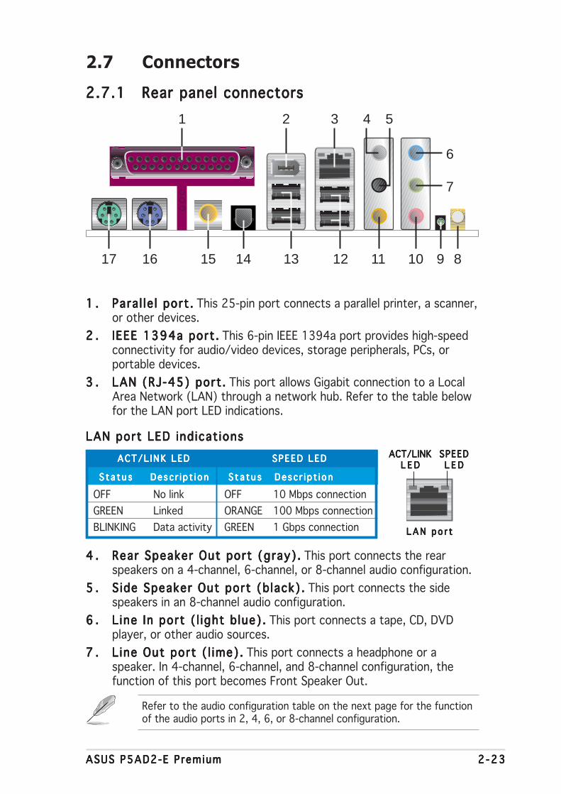
ASUS P5AD2-E PremiumASUS P5AD2-E PremiumASUS P5AD2-E PremiumASUS P5AD2-E PremiumASUS P5AD2-E Premium 2 -232 -232 -232 -232 -23
2.7 Connectors
2.7.12.7.12.7.12.7.12.7.1 Rear panel connectorsRear panel connectorsRear panel connectorsRear panel connectorsRear panel connectors
1 .1 .1 .1 .1 . Para l le l port .Para l le l port .Para l le l port .Para l le l port .Para l le l port . This 25-pin port connects a parallel printer, a scanner,or other devices.
2 .2 .2 .2 .2 . IEEE 1394a port .IEEE 1394a port .IEEE 1394a port .IEEE 1394a port .IEEE 1394a port . This 6-pin IEEE 1394a port provides high-speedconnectivity for audio/video devices, storage peripherals, PCs, orportable devices.
3 .3 .3 .3 .3 . LAN (RJ-45) port .LAN (RJ-45) port .LAN (RJ-45) port .LAN (RJ-45) port .LAN (RJ-45) port . This port allows Gigabit connection to a LocalArea Network (LAN) through a network hub. Refer to the table belowfor the LAN port LED indications.
4 .4 .4 .4 .4 . Rear Speaker Out port (gray).Rear Speaker Out port (gray).Rear Speaker Out port (gray).Rear Speaker Out port (gray).Rear Speaker Out port (gray). This port connects the rearspeakers on a 4-channel, 6-channel, or 8-channel audio configuration.
5 .5 .5 .5 .5 . S ide Speaker Out port (b lack).S ide Speaker Out port (b lack).S ide Speaker Out port (b lack).S ide Speaker Out port (b lack).S ide Speaker Out port (b lack). This port connects the sidespeakers in an 8-channel audio configuration.
6 .6 .6 .6 .6 . L ine In port ( l ight b lue).L ine In port ( l ight b lue).L ine In port ( l ight b lue).L ine In port ( l ight b lue).L ine In port ( l ight b lue). This port connects a tape, CD, DVDplayer, or other audio sources.
7 .7 .7 .7 .7 . L ine Out port ( l ime).L ine Out port ( l ime).L ine Out port ( l ime).L ine Out port ( l ime).L ine Out port ( l ime). This port connects a headphone or aspeaker. In 4-channel, 6-channel, and 8-channel configuration, thefunction of this port becomes Front Speaker Out.
Refer to the audio configuration table on the next page for the functionof the audio ports in 2, 4, 6, or 8-channel configuration.
ACT/L INK LEDACT/L INK LEDACT/L INK LEDACT/L INK LEDACT/L INK LED SPEED LEDSPEED LEDSPEED LEDSPEED LEDSPEED LED
S t a t u sS t a t u sS t a t u sS t a t u sS t a t u s Desc r i p t i onDesc r i p t i onDesc r i p t i onDesc r i p t i onDesc r i p t i on S t a t u sS t a t u sS t a t u sS t a t u sS t a t u s Desc r i p t i onDesc r i p t i onDesc r i p t i onDesc r i p t i onDesc r i p t i on
OFF No link OFF 10 Mbps connection
GREEN Linked ORANGE 100 Mbps connection
BLINKING Data activity GREEN 1 Gbps connection
LAN port LED ind icat ionsLAN port LED ind icat ionsLAN port LED ind icat ionsLAN port LED ind icat ionsLAN port LED ind icat ions
LAN po r tLAN po r tLAN po r tLAN po r tLAN po r t
SPEEDSPEEDSPEEDSPEEDSPEEDL E DL E DL E DL E DL E D
ACT/LINKACT/LINKACT/LINKACT/LINKACT/LINKL E DL E DL E DL E DL E D
12
1 3
15
2
13
4
141617 11
5
6
10
7
89

2 -242 -242 -242 -242 -24 Chapter 2 : Hardware in format ionChapter 2 : Hardware in format ionChapter 2 : Hardware in format ionChapter 2 : Hardware in format ionChapter 2 : Hardware in format ion
12 .12 .12 .12 .12 . USB 2.0 ports 3 and 4.USB 2.0 ports 3 and 4.USB 2.0 ports 3 and 4.USB 2.0 ports 3 and 4.USB 2.0 ports 3 and 4. These two 4-pin Universal Serial Bus(USB) ports are available for connecting USB 2.0 devices.
13 .13 .13 .13 .13 . USB 2.0 ports 1 and 2.USB 2.0 ports 1 and 2.USB 2.0 ports 1 and 2.USB 2.0 ports 1 and 2.USB 2.0 ports 1 and 2. These two 4-pin Universal Serial Bus(USB) ports are available for connecting USB 2.0 devices.
14 .14 .14 .14 .14 . Opt ica l S/PDIF Out portOpt ica l S/PDIF Out portOpt ica l S/PDIF Out portOpt ica l S/PDIF Out portOpt ica l S/PDIF Out port. This port connects an external audiooutput device via an optical S/PDIF cable.
15 .15 .15 .15 .15 . Coaxia l S/PDIF Out port .Coaxia l S/PDIF Out port .Coaxia l S/PDIF Out port .Coaxia l S/PDIF Out port .Coaxia l S/PDIF Out port . This port connects an external audiooutput device via a coaxial S/PDIF cable.
16 .16 .16 .16 .16 . PS/2 keyboard port (purple) .PS/2 keyboard port (purple) .PS/2 keyboard port (purple) .PS/2 keyboard port (purple) .PS/2 keyboard port (purple) . This port is for a PS/2 keyboard.
17 .17 .17 .17 .17 . PS/2 mouse port (green).PS/2 mouse port (green).PS/2 mouse port (green).PS/2 mouse port (green).PS/2 mouse port (green). This port is for a PS/2 mouse.
8 .8 .8 .8 .8 . Wire less LAN antenna port Wire less LAN antenna port Wire less LAN antenna port Wire less LAN antenna port Wire less LAN antenna port (Wireless Edition only)..... This portconnects to the optional dipolar antenna for the onboard WiFi-g™wireless LAN solution.
9 .9 .9 .9 .9 . Wire less LAN LED Wire less LAN LED Wire less LAN LED Wire less LAN LED Wire less LAN LED (Wireless Edition only). . . . . This green A I RA I RA I RA I RA I R LEDindicates the data transmission status of the onboard wireless LANadapter. Refer to the table below for the LED indications.
10 .10 .10 .10 .10 . Microphone port (p ink). Microphone port (p ink). Microphone port (p ink). Microphone port (p ink). Microphone port (p ink). This port connects a microphone.
11 .11 .11 .11 .11 . Center/Subwoofer port (yel low orange).Center/Subwoofer port (yel low orange).Center/Subwoofer port (yel low orange).Center/Subwoofer port (yel low orange).Center/Subwoofer port (yel low orange). This port connectsthe center/subwoofer speakers.
S t a t u sS t a t u sS t a t u sS t a t u sS t a t u s I nd i c a t i onI nd i c a t i onI nd i c a t i onI nd i c a t i onI nd i c a t i on
O nO nO nO nO n The onboard WiFi-g™ is on but has no data activity.
O f fO f fO f fO f fO f f The onboard WiFi-g™ is off.
F l ash ingF l ash ingF l ash ingF l ash ingF l ash ing The onboard WiFi-g™ is transmitting and/or receiving data.
Audio 2, 4, 6, or 8-channel conf igurat ionAudio 2, 4, 6, or 8-channel conf igurat ionAudio 2, 4, 6, or 8-channel conf igurat ionAudio 2, 4, 6, or 8-channel conf igurat ionAudio 2, 4, 6, or 8-channel conf igurat ion
Light BlueLight BlueLight BlueLight BlueLight Blue Line In Line In Line In Line In
L imeL imeL imeL imeL ime Line Out Front Speaker Out Front Speaker Out Front Speaker Out
P inkP inkP inkP inkP ink Mic In Mic In Mic In Mic In
GrayGrayGrayGrayGray — Rear Speaker Out Rear Speaker Out Rear Speaker Out
B lackB lackB lackB lackB lack — — — Side Speaker Out
Yellow OrangeYellow OrangeYellow OrangeYellow OrangeYellow Orange — — Center/Subwoofer Center/Subwoofer
P o r tP o r tP o r tP o r tP o r t 2 - channe l2 - channe l2 - channe l2 - channe l2 - channe l 4 - channe l4 - channe l4 - channe l4 - channe l4 - channe l 6 - channe l6 - channe l6 - channe l6 - channe l6 - channe l 8 - channe l8 - channe l8 - channe l8 - channe l8 - channe l(Headse t )(Headse t )(Headse t )(Headse t )(Headse t )
Wire less LAN LED indicat ionsWire less LAN LED indicat ionsWire less LAN LED indicat ionsWire less LAN LED indicat ionsWire less LAN LED indicat ions
Refer to the audio configuration table below for the function of theaudio ports in 2, 4, 6, or 8-channel configuration.

ASUS P5AD2-E PremiumASUS P5AD2-E PremiumASUS P5AD2-E PremiumASUS P5AD2-E PremiumASUS P5AD2-E Premium 2 -252 -252 -252 -252 -25
2 .2 .2 .2 .2 . Pr imary IDE connector (40-1 pin PRI_IDE1)Pr imary IDE connector (40-1 pin PRI_IDE1)Pr imary IDE connector (40-1 pin PRI_IDE1)Pr imary IDE connector (40-1 pin PRI_IDE1)Pr imary IDE connector (40-1 pin PRI_IDE1)
This connector is for an Ultra DMA 100/66 signal cable. The UltraDMA 100/66 signal cable has three connectors: a blue connector forthe primary IDE connector on the motherboard, a black connector foran Ultra DMA 100/66 IDE slave device (optical drive/hard disk drive),and a gray connector for an Ultra DMA 100/66 IDE master device (harddisk drive). If you install two hard disk drives, you must configure thesecond drive as a slave device by setting its jumper accordingly. Referto the hard disk documentation for the jumper settings.
2.7.22.7.22.7.22.7.22.7.2 Internal connectorsInternal connectorsInternal connectorsInternal connectorsInternal connectors
1 .1 .1 .1 .1 . F loppy disk dr ive connector (34-1 pin FLOPPY)Floppy disk dr ive connector (34-1 pin FLOPPY)Floppy disk dr ive connector (34-1 pin FLOPPY)Floppy disk dr ive connector (34-1 pin FLOPPY)Floppy disk dr ive connector (34-1 pin FLOPPY)
This connector is for the provided floppy disk drive (FDD) signal cable.Insert one end of the cable to this connector, then connect the otherend to the signal connector at the back of the floppy disk drive.
Pin 5 on the connector is removed to prevent incorrect cable connectionwhen using a FDD cable with a covered Pin 5.
• Pin 20 on the IDE connector is removed to match the covered holeon the Ultra DMA cable connector. This prevents incorrect insertionwhen you connect the IDE cable.
• Use the 80-conductor IDE cable for Ultra DMA 100/66 IDE devices.
P5A
D2-E
PR
EM
IUM
®
NOTE: Orient the red markings onthe floppy ribbon cable to PIN 1.
P5AD2-E PREMIUM Floppy disk drive connector
PIN 1 FLOPPY
P5A
D2-E
PR
EM
IUM
®
P5AD2-E PREMIUM IDE connector
NOTE: Orient the red markings(usually zigzag) on the IDEribbon cable to PIN 1.
PRI_IDE1PIN 1
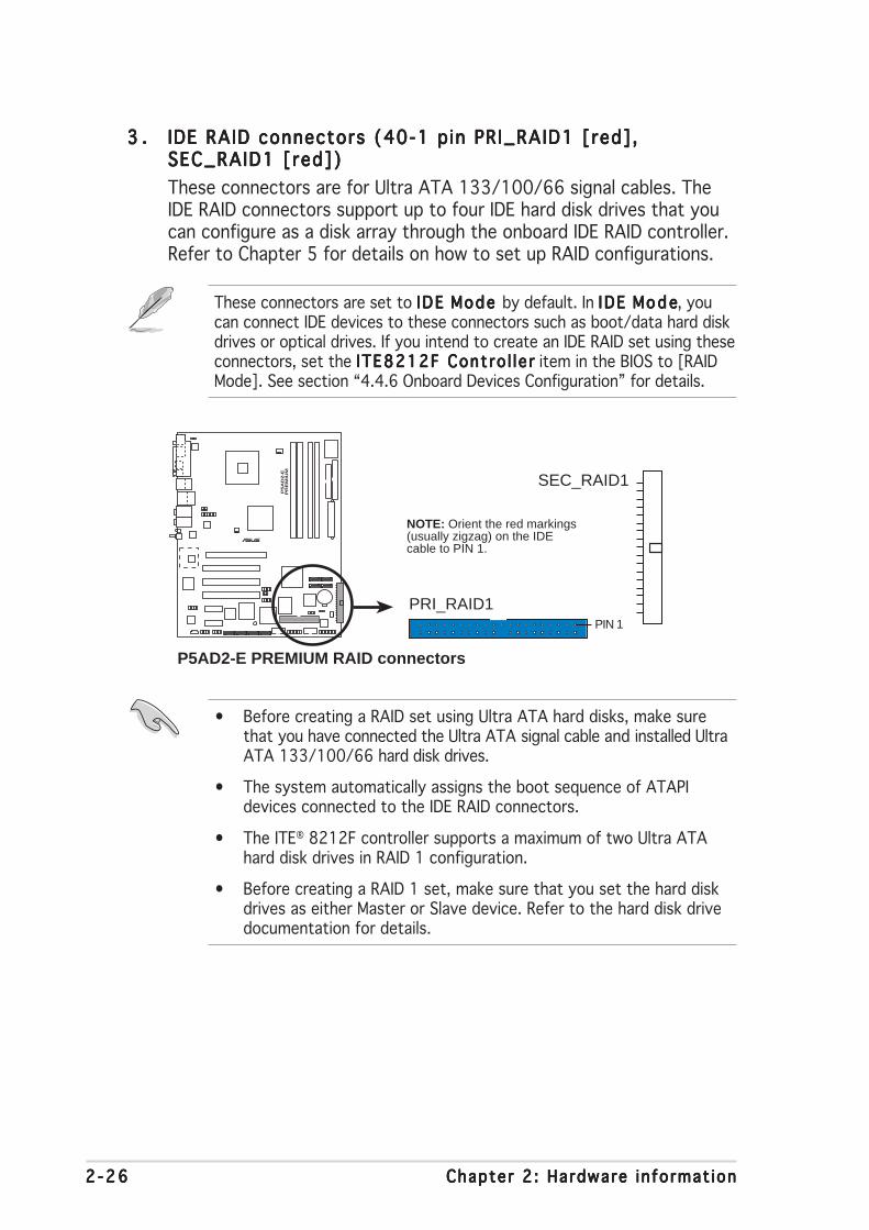
2 -262 -262 -262 -262 -26 Chapter 2 : Hardware in format ionChapter 2 : Hardware in format ionChapter 2 : Hardware in format ionChapter 2 : Hardware in format ionChapter 2 : Hardware in format ion
• Before creating a RAID set using Ultra ATA hard disks, make surethat you have connected the Ultra ATA signal cable and installed UltraATA 133/100/66 hard disk drives.
• The system automatically assigns the boot sequence of ATAPIdevices connected to the IDE RAID connectors.
• The ITE® 8212F controller supports a maximum of two Ultra ATAhard disk drives in RAID 1 configuration.
• Before creating a RAID 1 set, make sure that you set the hard diskdrives as either Master or Slave device. Refer to the hard disk drivedocumentation for details.
3 .3 .3 .3 .3 . IDE RAID connectors (40-1 pin PRI_RAID1 [red],IDE RAID connectors (40-1 pin PRI_RAID1 [red],IDE RAID connectors (40-1 pin PRI_RAID1 [red],IDE RAID connectors (40-1 pin PRI_RAID1 [red],IDE RAID connectors (40-1 pin PRI_RAID1 [red],SEC_RAID1 [red])SEC_RAID1 [red])SEC_RAID1 [red])SEC_RAID1 [red])SEC_RAID1 [red])
These connectors are for Ultra ATA 133/100/66 signal cables. TheIDE RAID connectors support up to four IDE hard disk drives that youcan configure as a disk array through the onboard IDE RAID controller.Refer to Chapter 5 for details on how to set up RAID configurations.
These connectors are set to IDE IDE IDE IDE IDE MMMMMode ode ode ode ode by default. In I DE IDE IDE IDE IDE MMMMMo d eo d eo d eo d eo d e, youcan connect IDE devices to these connectors such as boot/data hard diskdrives or optical drives. If you intend to create an IDE RAID set using theseconnectors, set the ITE8212F Contro l le rITE8212F Contro l le rITE8212F Contro l le rITE8212F Contro l le rITE8212F Contro l le r item in the BIOS to [RAIDMode]. See section “4.4.6 Onboard Devices Configuration” for details.
P5A
D2-E
PR
EM
IUM
®
P5AD2-E PREMIUM RAID connectors
NOTE: Orient the red markings(usually zigzag) on the IDEcable to PIN 1.
PRI_RAID1PIN 1
SEC_RAID1
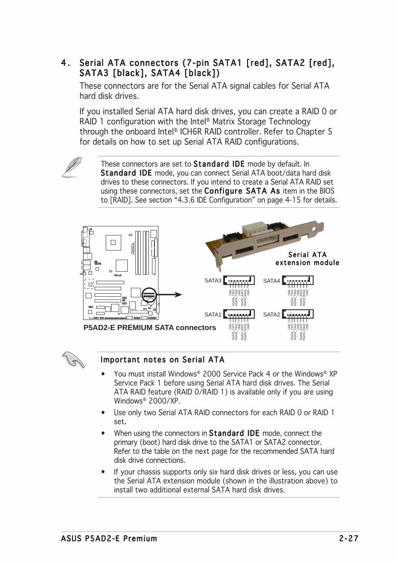
ASUS P5AD2-E PremiumASUS P5AD2-E PremiumASUS P5AD2-E PremiumASUS P5AD2-E PremiumASUS P5AD2-E Premium 2 -272 -272 -272 -272 -27
4 .4 .4 .4 .4 . Ser ia l ATA connectors (7-pin SATA1 [red], SATA2 [red],Ser ia l ATA connectors (7-pin SATA1 [red], SATA2 [red],Ser ia l ATA connectors (7-pin SATA1 [red], SATA2 [red],Ser ia l ATA connectors (7-pin SATA1 [red], SATA2 [red],Ser ia l ATA connectors (7-pin SATA1 [red], SATA2 [red],SATA3 [black], SATA4 [black])SATA3 [black], SATA4 [black])SATA3 [black], SATA4 [black])SATA3 [black], SATA4 [black])SATA3 [black], SATA4 [black])
These connectors are for the Serial ATA signal cables for Serial ATAhard disk drives.
If you installed Serial ATA hard disk drives, you can create a RAID 0 orRAID 1 configuration with the Intel® Matrix Storage Technologythrough the onboard Intel® ICH6R RAID controller. Refer to Chapter 5for details on how to set up Serial ATA RAID configurations.
These connectors are set to Standard IDE Standard IDE Standard IDE Standard IDE Standard IDE mode by default. InSSSSStandard IDE tandard IDE tandard IDE tandard IDE tandard IDE mode, you can connect Serial ATA boot/data hard diskdrives to these connectors. If you intend to create a Serial ATA RAID setusing these connectors, set the Conf igure SATA As Conf igure SATA As Conf igure SATA As Conf igure SATA As Conf igure SATA As item in the BIOSto [RAID]. See section “4.3.6 IDE Configuration” on page 4-15 for details.
Important notes on Ser ia l ATAImportant notes on Ser ia l ATAImportant notes on Ser ia l ATAImportant notes on Ser ia l ATAImportant notes on Ser ia l ATA
• You must install Windows® 2000 Service Pack 4 or the Windows® XPService Pack 1 before using Serial ATA hard disk drives. The SerialATA RAID feature (RAID 0/RAID 1) is available only if you are usingWindows® 2000/XP.
• Use only two Serial ATA RAID connectors for each RAID 0 or RAID 1set.
• When using the connectors in SSSSStandard IDE tandard IDE tandard IDE tandard IDE tandard IDE mode, connect theprimary (boot) hard disk drive to the SATA1 or SATA2 connector.Refer to the table on the next page for the recommended SATA harddisk drive connections.
• If your chassis supports only six hard disk drives or less, you can usethe Serial ATA extension module (shown in the illustration above) toinstall two additional external SATA hard disk drives.
Se r i a l ATASe r i a l ATASe r i a l ATASe r i a l ATASe r i a l ATAextens i on modu l eex tens i on modu l eex tens i on modu l eex tens i on modu l eex tens i on modu l e
P5A
D2-E
PR
EM
IUM
®
P5AD2-E PREMIUM SATA connectors
SATA1
GN
DR
SAT
A_T
XP
1R
SAT
A_T
XN
1G
ND
RS
ATA
_RX
P1
RS
ATA
_RX
N1
GN
D
SATA4G
ND
RS
ATA
_TX
P4
RS
ATA
_TX
N4
GN
DR
SAT
A_R
XP
4R
SAT
A_R
XN
4G
ND
SATA3
GN
DR
SAT
A_T
XP
3R
SAT
A_T
XN
3G
ND
RS
ATA
_RX
P3
RS
ATA
_RX
N3
GN
D
SATA2
GN
DR
SAT
A_T
XP
2R
SAT
A_T
XN
2G
ND
RS
ATA
_RX
P2
RS
ATA
_RX
N2
GN
D
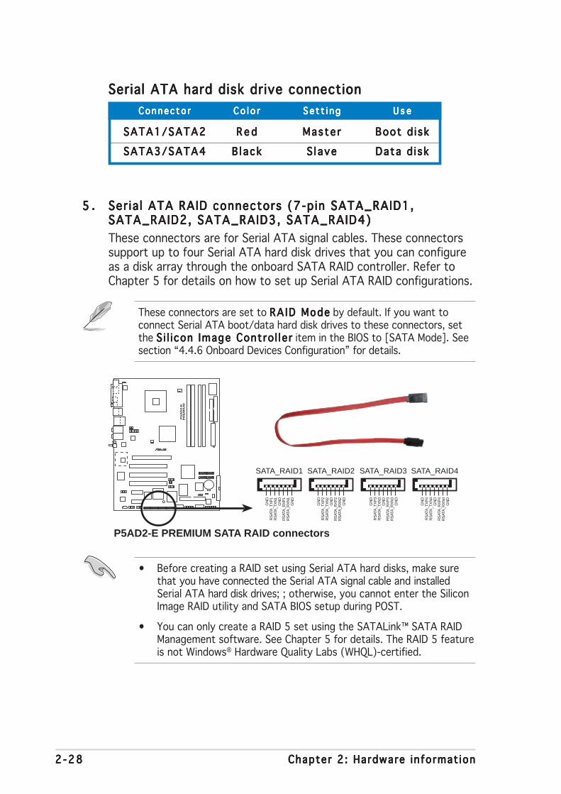
2 -282 -282 -282 -282 -28 Chapter 2 : Hardware in format ionChapter 2 : Hardware in format ionChapter 2 : Hardware in format ionChapter 2 : Hardware in format ionChapter 2 : Hardware in format ion
5 .5 .5 .5 .5 . Ser ia l ATA RAID connectors (7-pin SATA_RAID1,Ser ia l ATA RAID connectors (7-pin SATA_RAID1,Ser ia l ATA RAID connectors (7-pin SATA_RAID1,Ser ia l ATA RAID connectors (7-pin SATA_RAID1,Ser ia l ATA RAID connectors (7-pin SATA_RAID1,SATA_RAID2, SATA_RAID3, SATA_RAID4)SATA_RAID2, SATA_RAID3, SATA_RAID4)SATA_RAID2, SATA_RAID3, SATA_RAID4)SATA_RAID2, SATA_RAID3, SATA_RAID4)SATA_RAID2, SATA_RAID3, SATA_RAID4)
These connectors are for Serial ATA signal cables. These connectorssupport up to four Serial ATA hard disk drives that you can configureas a disk array through the onboard SATA RAID controller. Refer toChapter 5 for details on how to set up Serial ATA RAID configurations.
These connectors are set to RA ID ModeRA ID ModeRA ID ModeRA ID ModeRA ID Mode by default. If you want toconnect Serial ATA boot/data hard disk drives to these connectors, setthe S i l i con Image Contro l le rS i l i con Image Contro l le rS i l i con Image Contro l le rS i l i con Image Contro l le rS i l i con Image Contro l le r item in the BIOS to [SATA Mode]. Seesection “4.4.6 Onboard Devices Configuration” for details.
• Before creating a RAID set using Serial ATA hard disks, make surethat you have connected the Serial ATA signal cable and installedSerial ATA hard disk drives; ; otherwise, you cannot enter the SiliconImage RAID utility and SATA BIOS setup during POST.
• You can only create a RAID 5 set using the SATALink™ SATA RAIDManagement software. See Chapter 5 for details. The RAID 5 featureis not Windows® Hardware Quality Labs (WHQL)-certified.
Serial ATA hard disk drive connectionSerial ATA hard disk drive connectionSerial ATA hard disk drive connectionSerial ATA hard disk drive connectionSerial ATA hard disk drive connection
Connec to rConnec to rConnec to rConnec to rConnec to r C o l o rC o l o rC o l o rC o l o rC o l o r S e t t i n gS e t t i n gS e t t i n gS e t t i n gS e t t i n g U s eU s eU s eU s eU s e
SATA1/SATA2SATA1/SATA2SATA1/SATA2SATA1/SATA2SATA1/SATA2 R e dR e dR e dR e dR e d Maste rMas te rMas te rMas te rMas te r Boot d i skBoot d i skBoot d i skBoot d i skBoot d i sk
SATA3/SATA4SATA3/SATA4SATA3/SATA4SATA3/SATA4SATA3/SATA4 B l ackB l a ckB l a ckB l a ckB l a ck S l aveS l aveS l aveS l aveS l ave Data d i skData d i skData d i skData d i skData d i sk
P5A
D2-E
PR
EM
IUM
®
P5AD2-E PREMIUM SATA RAID connectors
GN
DR
SAT
A_T
XP
2R
SAT
A_T
XN
2G
ND
RS
ATA
_RX
P2
RS
ATA
_RX
N2
GN
D
SATA_RAID1
GN
DR
SAT
A_T
XP
1R
SAT
A_T
XN
1G
ND
RS
ATA
_RX
P1
RS
ATA
_RX
N1
GN
D
SATA_RAID2
GN
DR
SAT
A_T
XP
4R
SAT
A_T
XN
4G
ND
RS
ATA
_RX
P4
RS
ATA
_RX
N4
GN
D
SATA_RAID3
GN
DR
SAT
A_T
XP
3R
SAT
A_T
XN
3G
ND
RS
ATA
_RX
P3
RS
ATA
_RX
N3
GN
D
SATA_RAID4

ASUS P5AD2-E PremiumASUS P5AD2-E PremiumASUS P5AD2-E PremiumASUS P5AD2-E PremiumASUS P5AD2-E Premium 2 -292 -292 -292 -292 -29
7 .7 .7 .7 .7 . Opt ica l dr ive audio connector (4-pin CD)Optica l dr ive audio connector (4-pin CD)Optica l dr ive audio connector (4-pin CD)Optica l dr ive audio connector (4-pin CD)Optica l dr ive audio connector (4-pin CD)
This connector is for the 4-pin audio cable that connects to the audioconnector at the back of the optical drive.
Enable the CD-IN function in the audio utility when using thisconnector.
6 .6 .6 .6 .6 . Dig ita l audio connector (6-1 pin SPDIF)Dig ita l audio connector (6-1 pin SPDIF)Dig ita l audio connector (6-1 pin SPDIF)Dig ita l audio connector (6-1 pin SPDIF)Dig ita l audio connector (6-1 pin SPDIF)
This connector is for an additional Sony/Philips Digital Interface(S/PDIF) port(s). Connect the S/PDIF module cable to this connector,then install the module to a slot opening at the back of the systemchassis.
The S/PDIF module is purchased separately.P
5A
D2-E
PR
EM
IUM
®
P5AD2-E PREMIUM Digital audio connector
SPDIF
GN
D
+5V
SP
DIF
_IN
SP
DIF
_OU
T
GN
D
1
P5A
D2-E
PR
EM
IUM
®
P5AD2-E PREMIUM CD audio connector
CD
Rig
ht A
udio
Cha
nnel
Left
Aud
io C
hann
elG
roun
dG
roun
d
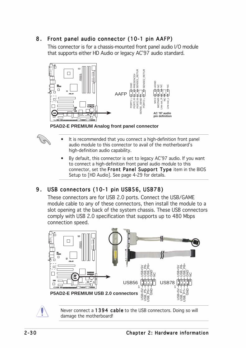
2 -302 -302 -302 -302 -30 Chapter 2 : Hardware in format ionChapter 2 : Hardware in format ionChapter 2 : Hardware in format ionChapter 2 : Hardware in format ionChapter 2 : Hardware in format ion
9 .9 .9 .9 .9 . USB connectors (10-1 pin USB56, USB78)USB connectors (10-1 pin USB56, USB78)USB connectors (10-1 pin USB56, USB78)USB connectors (10-1 pin USB56, USB78)USB connectors (10-1 pin USB56, USB78)
These connectors are for USB 2.0 ports. Connect the USB/GAMEmodule cable to any of these connectors, then install the module to aslot opening at the back of the system chassis. These USB connectorscomply with USB 2.0 specification that supports up to 480 Mbpsconnection speed.
8 .8 .8 .8 .8 . Front panel audio connector (10-1 pin AAFP)Front panel audio connector (10-1 pin AAFP)Front panel audio connector (10-1 pin AAFP)Front panel audio connector (10-1 pin AAFP)Front panel audio connector (10-1 pin AAFP)
This connector is for a chassis-mounted front panel audio I/O modulethat supports either HD Audio or legacy AC’97 audio standard.
Never connect a 1394 cab le1394 cab le1394 cab le1394 cab le1394 cab le to the USB connectors. Doing so willdamage the motherboard!
• It is recommended that you connect a high-definition front panelaudio module to this connector to avail of the motherboard’shigh-definition audio capability.
• By default, this connector is set to legacy AC’97 audio. If you wantto connect a high-definition front panel audio module to thisconnector, set the Front Pane l Support Type Front Pane l Support Type Front Pane l Support Type Front Pane l Support Type Front Pane l Support Type item in the BIOSSetup to [HD Audio]. See page 4-29 for details.
P5A
D2-E
PR
EM
IUM
®
P5AD2-E PREMIUM Analog front panel connector
AC ‘97 audiopin definition
AAFP
NC
MIC
2
Line
out
_R
Line
out
_L
NC
NC
MIC
PW
RN
CA
GN
D
SE
NS
E2_
RE
TU
R
PO
RT
1 L
PO
RT
2 R
PO
RT
2 L
SE
NS
E1_
RE
TU
RS
EN
SE
_SE
ND
PO
RT
1 R
PR
ES
EN
CE
#G
ND
P5A
D2-E
PR
EM
IUM
®
P5AD2-E PREMIUM USB 2.0 connectors
USB56
US
B+
5VU
SB
_P6-
US
B_P
6+G
ND
NC
US
B+
5VU
SB
_P5-
US
B_P
5+G
ND
1USB78
US
B+
5VU
SB
_P8-
US
B_P
8+G
ND
NC
US
B+
5VU
SB
_P7-
US
B_P
7+G
ND
1
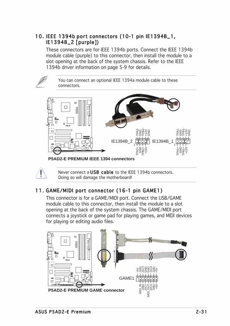
ASUS P5AD2-E PremiumASUS P5AD2-E PremiumASUS P5AD2-E PremiumASUS P5AD2-E PremiumASUS P5AD2-E Premium 2 -312 -312 -312 -312 -31
10 .10 .10 .10 .10 . IEEE 1394b IEEE 1394b IEEE 1394b IEEE 1394b IEEE 1394b port por t por t por t por t connectors (10-1 pin IE1394B_1,connectors (10-1 pin IE1394B_1,connectors (10-1 pin IE1394B_1,connectors (10-1 pin IE1394B_1,connectors (10-1 pin IE1394B_1,IE1394B_2IE1394B_2IE1394B_2IE1394B_2IE1394B_2 [purp le] [purp le] [purp le] [purp le] [purp le])))))
These connectors are for IEEE 1394b ports. Connect the IEEE 1394bmodule cable (purple) to this connector, then install the module to aslot opening at the back of the system chassis. Refer to the IEEE1394b driver information on page 5-9 for details.
11 .11 .11 .11 .11 . GAME/MIDI port connector (16-1 pin GAME1)GAME/MIDI port connector (16-1 pin GAME1)GAME/MIDI port connector (16-1 pin GAME1)GAME/MIDI port connector (16-1 pin GAME1)GAME/MIDI port connector (16-1 pin GAME1)
This connector is for a GAME/MIDI port. Connect the USB/GAMEmodule cable to this connector, then install the module to a slotopening at the back of the system chassis. The GAME/MIDI portconnects a joystick or game pad for playing games, and MIDI devicesfor playing or editing audio files.
You can connect an optional IEEE 1394a module cable to theseconnectors.
P5A
D2-E
PR
EM
IUM
®
P5AD2-E PREMIUM IEEE 1394 connectors
IE1394B_21
TP
A1-
GN
DT
PB
1-+
12V
GN
D
TP
A1+
GN
DT
PB
1++
12V
IE1394B_11
TP
A2-
GN
DT
PB
2-+
12V
GN
D
TP
A2+
GN
DT
PB
2++
12V
Never connect a USB cab le USB cab le USB cab le USB cab le USB cab le to the IEEE 1394b connectors.Doing so will damage the motherboard!
P5A
D2-E
PR
EM
IUM
®
P5AD2-E PREMIUM GAME connector
GAME1
+5V
+5V
J2B
1J2
CX
MID
I_O
UT
J2C
YJ2
B2
MID
I_IN
J1B
1J1
CX
GN
DG
ND
J1C
YJ1
B2
+5V
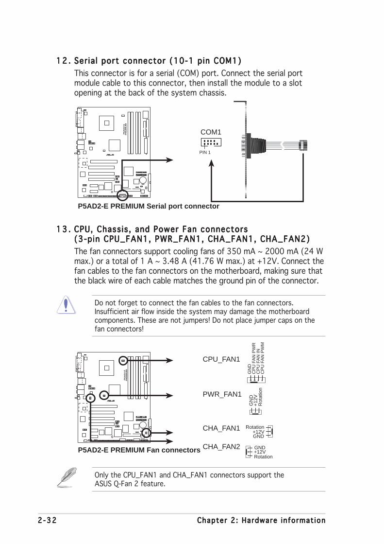
2 -322 -322 -322 -322 -32 Chapter 2 : Hardware in format ionChapter 2 : Hardware in format ionChapter 2 : Hardware in format ionChapter 2 : Hardware in format ionChapter 2 : Hardware in format ion
12 .12 .12 .12 .12 . Ser ia l port connector (10-1 pin COM1)Ser ia l port connector (10-1 pin COM1)Ser ia l port connector (10-1 pin COM1)Ser ia l port connector (10-1 pin COM1)Ser ia l port connector (10-1 pin COM1)
This connector is for a serial (COM) port. Connect the serial portmodule cable to this connector, then install the module to a slotopening at the back of the system chassis.
13 .13 .13 .13 .13 . CPU, Chass is , and Power Fan connectorsCPU, Chass is , and Power Fan connectorsCPU, Chass is , and Power Fan connectorsCPU, Chass is , and Power Fan connectorsCPU, Chass is , and Power Fan connectors(3-pin CPU_FAN1, PWR_FAN1, CHA_FAN1, CHA_FAN2)(3-pin CPU_FAN1, PWR_FAN1, CHA_FAN1, CHA_FAN2)(3-pin CPU_FAN1, PWR_FAN1, CHA_FAN1, CHA_FAN2)(3-pin CPU_FAN1, PWR_FAN1, CHA_FAN1, CHA_FAN2)(3-pin CPU_FAN1, PWR_FAN1, CHA_FAN1, CHA_FAN2)
The fan connectors support cooling fans of 350 mA ~ 2000 mA (24 Wmax.) or a total of 1 A ~ 3.48 A (41.76 W max.) at +12V. Connect thefan cables to the fan connectors on the motherboard, making sure thatthe black wire of each cable matches the ground pin of the connector.
Only the CPU_FAN1 and CHA_FAN1 connectors support theASUS Q-Fan 2 feature.
Do not forget to connect the fan cables to the fan connectors.Insufficient air flow inside the system may damage the motherboardcomponents. These are not jumpers! Do not place jumper caps on thefan connectors!
P5A
D2-E
PR
EM
IUM
®
P5AD2-E PREMIUM Serial port connector
PIN 1
COM1P
5A
D2-E
PR
EM
IUM
®
P5AD2-E PREMIUM Fan connectors
CPU_FAN1
CHA_FAN1
PWR_FAN1
GN
D
Rot
atio
n+
12V
GND
Rotation+12V
GN
DC
PU
FA
N P
WR
CP
U F
AN
INC
PU
FA
N P
WM
GND
Rotation+12V
CHA_FAN2

ASUS P5AD2-E PremiumASUS P5AD2-E PremiumASUS P5AD2-E PremiumASUS P5AD2-E PremiumASUS P5AD2-E Premium 2 -332 -332 -332 -332 -33
14 .14 .14 .14 .14 . Chass is intrus ion connector (4-1 pin CHASSIS1)Chassis intrus ion connector (4-1 pin CHASSIS1)Chassis intrus ion connector (4-1 pin CHASSIS1)Chassis intrus ion connector (4-1 pin CHASSIS1)Chassis intrus ion connector (4-1 pin CHASSIS1)
This connector is for a chassis-mounted intrusion detection sensor orswitch. Connect one end of the chassis intrusion sensor or switchcable to this connector. The chassis intrusion sensor or switch sends ahigh-level signal to this connector when a chassis component isremoved or replaced. The signal is then generated as a chassisintrusion event.
By default, the pins labeled “Chassis Signal” and “Ground” are shortedwith a jumper cap. Remove the jumper caps only when you intend touse the chassis intrusion detection feature.
15 .15 .15 .15 .15 . Gigabit LAN port connector (16-1 pin LAN2 [black])Gigabit LAN port connector (16-1 pin LAN2 [black])Gigabit LAN port connector (16-1 pin LAN2 [black])Gigabit LAN port connector (16-1 pin LAN2 [black])Gigabit LAN port connector (16-1 pin LAN2 [black])
This connector is for a Gigabit LAN (RJ-45) port. Connect the LAN(RJ-45) port module cable to this connector, then install the moduleto an opening at the back of the system chassis. The Gigabit LAN(RJ-45) port allows up to 1 Gbps LAN or Internet connection.
P5A
D2-E
PR
EM
IUM
®
P5AD2-E PREMIUM Chassis intrusion connector
CHASSIS1+
5VS
B_M
B
Cha
ssis
Sig
nal
GN
D
(Default)
P5A
D2-E
PR
EM
IUM
®
P5AD2-E PREMIUM Gigabit LAN port connector LIN
K_1
00#
LIN
K_G
B#
Act
#LE
D_P
ower
CT
RG
ND
GN
DT
D1+
TD
1-T
D2+
TD
2-T
D3+
TD
3-T
D4+
TD
4-
LAN2
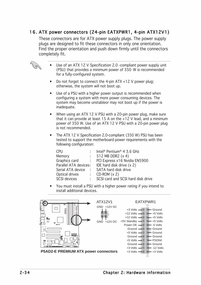
2 -342 -342 -342 -342 -34 Chapter 2 : Hardware in format ionChapter 2 : Hardware in format ionChapter 2 : Hardware in format ionChapter 2 : Hardware in format ionChapter 2 : Hardware in format ion
16 .16 .16 .16 .16 . ATX power connectors (24-pin EATXPWR1, 4-pin ATX12V1)ATX power connectors (24-pin EATXPWR1, 4-pin ATX12V1)ATX power connectors (24-pin EATXPWR1, 4-pin ATX12V1)ATX power connectors (24-pin EATXPWR1, 4-pin ATX12V1)ATX power connectors (24-pin EATXPWR1, 4-pin ATX12V1)
These connectors are for ATX power supply plugs. The power supplyplugs are designed to fit these connectors in only one orientation.Find the proper orientation and push down firmly until the connectorscompletely fit.
• Use of an ATX 12 V Specification 2.0 -compliant power supply unit(PSU) that provides a minimum power of 350 W is recommendedfor a fully-configured system.
• Do not forget to connect the 4-pin ATX +12 V power plug;otherwise, the system will not boot up.
• Use of a PSU with a higher power output is recommended whenconfiguring a system with more power consuming devices. Thesystem may become unstableor may not boot up if the power isinadequate.
• When using an ATX 12 V PSU with a 20-pin power plug, make surethat it can provide at least 15 A on the +12 V lead, and a minimumpower of 350 W. Use of an ATX 12 V PSU with a 20-pin power plugis not recommended.
• The ATX 12 V Specification 2.0-compliant (350 W) PSU has beentested to support the motherboard power requirements with thefollowing configuration:
CPU : Intel® Pentium® 4 3.6 GHzMemory : 512 MB DDR2 (x 4)Graphics card : PCI Express x16 Nvidia EN5900Parallel ATA devices : IDE hard disk drive (x 2)Serial ATA device : SATA hard disk driveOptical drives : CD-ROM (x 2)SCSI devices : SCSI card and SCSI hard disk drive
• You must install a PSU with a higher power rating if you intend toinstall additional devices.
P5A
D2-E
PR
EM
IUM
®
P5AD2-E PREMIUM ATX power connectors
EATXPWR1ATX12V1
+3 Volts+3 VoltsGround+5 Volts
+5 VoltsGround
GroundPower OK
+5V Standby+12 Volts
-5 Volts
+5 Volts
+3 Volts-12 VoltsGround
GroundGroundPSON#
Ground
+5 Volts
+12 Volts+3 Volts
+5 VoltsGround
+12V DCGND
+12V DCGND
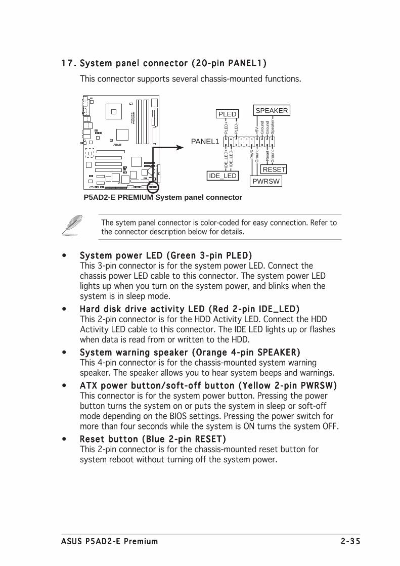
ASUS P5AD2-E PremiumASUS P5AD2-E PremiumASUS P5AD2-E PremiumASUS P5AD2-E PremiumASUS P5AD2-E Premium 2 -352 -352 -352 -352 -35
• System power LED (Green 3-pin PLED)System power LED (Green 3-pin PLED)System power LED (Green 3-pin PLED)System power LED (Green 3-pin PLED)System power LED (Green 3-pin PLED)This 3-pin connector is for the system power LED. Connect thechassis power LED cable to this connector. The system power LEDlights up when you turn on the system power, and blinks when thesystem is in sleep mode.
• Hard disk dr ive act iv ity LED (Red 2-pin IDE_LED)Hard d isk dr ive act iv ity LED (Red 2-pin IDE_LED)Hard d isk dr ive act iv ity LED (Red 2-pin IDE_LED)Hard d isk dr ive act iv ity LED (Red 2-pin IDE_LED)Hard d isk dr ive act iv ity LED (Red 2-pin IDE_LED)This 2-pin connector is for the HDD Activity LED. Connect the HDDActivity LED cable to this connector. The IDE LED lights up or flasheswhen data is read from or written to the HDD.
• System warning speaker (Orange 4-pin SPEAKER)System warning speaker (Orange 4-pin SPEAKER)System warning speaker (Orange 4-pin SPEAKER)System warning speaker (Orange 4-pin SPEAKER)System warning speaker (Orange 4-pin SPEAKER)This 4-pin connector is for the chassis-mounted system warningspeaker. The speaker allows you to hear system beeps and warnings.
• ATX power button/soft-off button (Yel low 2-pin PWRSW)ATX power button/soft-off button (Yel low 2-pin PWRSW)ATX power button/soft-off button (Yel low 2-pin PWRSW)ATX power button/soft-off button (Yel low 2-pin PWRSW)ATX power button/soft-off button (Yel low 2-pin PWRSW)This connector is for the system power button. Pressing the powerbutton turns the system on or puts the system in sleep or soft-offmode depending on the BIOS settings. Pressing the power switch formore than four seconds while the system is ON turns the system OFF.
• Reset button (Blue 2-pin RESET)Reset button (Blue 2-pin RESET)Reset button (Blue 2-pin RESET)Reset button (Blue 2-pin RESET)Reset button (Blue 2-pin RESET)This 2-pin connector is for the chassis-mounted reset button forsystem reboot without turning off the system power.
17 .17 .17 .17 .17 . System panel connector (20-pin PANEL1)System panel connector (20-pin PANEL1)System panel connector (20-pin PANEL1)System panel connector (20-pin PANEL1)System panel connector (20-pin PANEL1)
This connector supports several chassis-mounted functions.
The sytem panel connector is color-coded for easy connection. Refer tothe connector description below for details.
P5A
D2-E
PR
EM
IUM
®
P5AD2-E PREMIUM System panel connector
PANEL1
PLE
D-
PW
R+
5V Spe
aker
SPEAKERPLED
Gro
und
RESET
Gro
und
Res
etG
roun
dG
roun
d
PWRSW
PLE
D+
IDE
_LE
D-
IDE
_LE
D+
IDE_LED

2 -362 -362 -362 -362 -36 Chapter 2 : Hardware in format ionChapter 2 : Hardware in format ionChapter 2 : Hardware in format ionChapter 2 : Hardware in format ionChapter 2 : Hardware in format ion

3Powering up
This chapter describes the power upsequence, the vocal POST messages,and ways of shutting down thesystem.

ASUS P5AD2-E PremiumASUS P5AD2-E PremiumASUS P5AD2-E PremiumASUS P5AD2-E PremiumASUS P5AD2-E Premium
Chapter summary 33.1 Starting up for the first time ................................................ 3-1
3.2 Powering off the computer .................................................. 3-2
3.3 ASUS POST Reporter™ .......................................................... 3-3

ASUS P5AD2-E PremiumASUS P5AD2-E PremiumASUS P5AD2-E PremiumASUS P5AD2-E PremiumASUS P5AD2-E Premium 3 - 13 - 13 - 13 - 13 - 1
3.1 Starting up for the first time
1. After making all the connections, replace the system case cover.
2. Be sure that all switches are off.
3. Connect the power cord to the power connector at the back of thesystem chassis.
4. Connect the power cord to a power outlet that is equipped with asurge protector.
5. Turn on the devices in the following order:
a. Monitor
b.External SCSI devices (starting with the last device on the chain)
c. System power
6. After applying power, the system power LED on the system frontpanel case lights up. For systems withATX power supplies, the systemLED lights up when you press the ATX power button. If your monitorcomplies with “green” standards or if it has a “power standby”feature, the monitor LED may light up or switch between orange andgreen after the system LED turns on.
The system then runs the power-on self tests or POST. While thetests are running, the BIOS beeps (see BIOS beep codes table below)or additional messages appear on the screen. If you do not seeanything within 30 seconds from the time you turned on the power,the system may have failed a power-on test. Check the jumpersettings and connections or call your retailer for assistance.
AMI BIOS beep codesAMI BIOS beep codesAMI BIOS beep codesAMI BIOS beep codesAMI BIOS beep codes
Beep Desc r i p t i onBeep Desc r i p t i onBeep Desc r i p t i onBeep Desc r i p t i onBeep Desc r i p t i on E r r o rE r r o rE r r o rE r r o rE r r o r
One beep Keyboard controller errorRefresh Time errorNo master drive detected
Two continuous beeps followed by Floppy controller failuretwo short beeps
Two continuous beeps followed by Hardware component failurefour short beeps
7. At power on, hold down the <Delete> key to enter the BIOS Setup.Follow the instructions in Chapter 4.

3 - 23 - 23 - 23 - 23 - 2 Chapter 3 : Power ing upChapter 3 : Power ing upChapter 3 : Power ing upChapter 3 : Power ing upChapter 3 : Power ing up
3.2 Powering off the computer
3.2.13.2.13.2.13.2.13.2.1 Using the OS shut down functionUsing the OS shut down functionUsing the OS shut down functionUsing the OS shut down functionUsing the OS shut down function
If you are using Windows® 2000:
1. Click the Start Start Start Start Start button then click Shut Down. . .Shut Down. . .Shut Down. . .Shut Down. . .Shut Down. . .
2. Make sure that the Shut DownShut DownShut DownShut DownShut Down option button is selected, then clickthe OK OK OK OK OK button to shut down the computer.
3. The power supply should turn off after Windows® shuts down.
If you are using Windows® XP:
1. Click the Start Start Start Start Start button then select Turn Off Computer .Turn Off Computer .Turn Off Computer .Turn Off Computer .Turn Off Computer .
2. Click the Turn Off Turn Off Turn Off Turn Off Turn Off button to shut down the computer.
3. The power supply should turn off after Windows® shuts down.
3.2.23.2.23.2.23.2.23.2.2 Using the dual function power switchUsing the dual function power switchUsing the dual function power switchUsing the dual function power switchUsing the dual function power switch
While the system is ON, pressing the power switch for less than fourseconds puts the system to sleep mode or to soft-off mode, depending onthe BIOS setting. Pressing the power switch for more than four secondslets the system enter the soft-off mode regardless of the BIOS setting.Refer to section “4.5 Power Menu” in Chapter 4 for details.

ASUS P5AD2-E PremiumASUS P5AD2-E PremiumASUS P5AD2-E PremiumASUS P5AD2-E PremiumASUS P5AD2-E Premium 3 - 33 - 33 - 33 - 33 - 3
3.3 ASUS POST Reporter™
This motherboard includes the Winbond speech controller to support aspecial feature called the ASUS POST Reporter™. This feature lets you hearvocal messages during POST that alerts you of system events and bootstatus. In case of a boot failure, you will hear the specific cause of theproblem.
These POST messages are customizable using the Winbond Voice Editorsoftware that came with your package. You can record your own messagesto replace the default messages.
3.3.13.3.13.3.13.3.13.3.1 Vocal POST messagesVocal POST messagesVocal POST messagesVocal POST messagesVocal POST messages
Following is a list of the default POST messages and the correspondingactions you can take:
POST MessagePOST MessagePOST MessagePOST MessagePOST Message A c t i o nA c t i o nA c t i o nA c t i o nA c t i o n
No CPU installed • Install a supported processor to theCPU socket. See section “2.3 CentralProcessing Unit (CPU)” for details.
System failed CPU test • Check the CPU if properly installed.
• Call ASUS technical support forassistance. See the ASUS contactinformation on the inside front coverof this user guide.
System failed memory test • Install supported DDR2 DIMMs into thememory sockets.
• Check if the DIMMs on the DIMMsockets are properly installed.
• Make sure that your DIMMs are notdefective.
• Refer to section “2.4 System memory”for instructions on installing a DIMM.
System failed VGA test • Install a PCI graphics card into one ofthe PCI slots, or a PCI Express AGPcard into the PCI Express x16 slot.
• Make sure that your graphics card isnot defective.
System failed due to CPU • Check your CPU overclocking settingsin the BIOS setup and restore thedefault CPU parameters.
No keyboard detected • Check if your keyboard is properlyconnected to the purple PS/2connector on the rear panel.
• See section “2.7.1 Rear panelconnectors” for the location of theconnector.
No IDE hard disk detected • Make sure you have connected an IDEhard disk drive to one of the IDEconnectors on the motherboard.

3 - 43 - 43 - 43 - 43 - 4 Chapter 3 : Power ing upChapter 3 : Power ing upChapter 3 : Power ing upChapter 3 : Power ing upChapter 3 : Power ing up
POST MessagePOST MessagePOST MessagePOST MessagePOST Message A c t i o nA c t i o nA c t i o nA c t i o nA c t i o n
CPU temperature too high • Check if the CPU fan is workingproperly.
CPU fan failed • Check the CPU fan and make sure itturns on after you apply power to thesystem.
• Make sure that your CPU fan supportsthe fan speed detection function.
CPU voltage out of range • Check your power supply and makesure it is not defective.
• Call ASUS technical support forassistance. See the “ASUS contactinformation” on the inside front coverof this user guide.
Computer now booting from operating • No action required
system
You can enable or disable the ASUS POST Reporter™ in the SpeechSpeechSpeechSpeechSpeechConf igurat ion Conf igurat ion Conf igurat ion Conf igurat ion Conf igurat ion option in the BIOS setup. See section 4.4.8 for details.
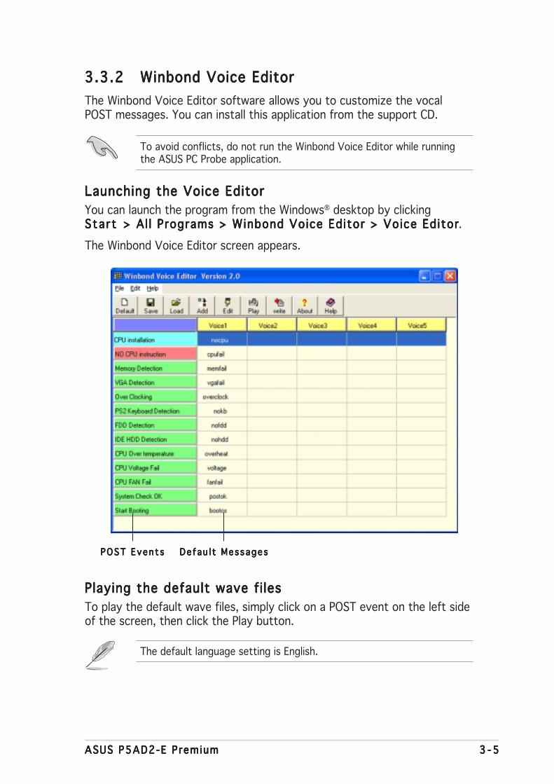
ASUS P5AD2-E PremiumASUS P5AD2-E PremiumASUS P5AD2-E PremiumASUS P5AD2-E PremiumASUS P5AD2-E Premium 3 - 53 - 53 - 53 - 53 - 5
3.3.23.3.23.3.23.3.23.3.2 Winbond Voice EditorWinbond Voice EditorWinbond Voice EditorWinbond Voice EditorWinbond Voice Editor
The Winbond Voice Editor software allows you to customize the vocalPOST messages. You can install this application from the support CD.
Launching the Voice EditorLaunching the Voice EditorLaunching the Voice EditorLaunching the Voice EditorLaunching the Voice Editor
You can launch the program from the Windows® desktop by clickingSta r tSta r tSta r tSta r tSta r t > Al l Programs > Winbond Voice Editor > Voice Editor> Al l Programs > Winbond Voice Editor > Voice Editor> Al l Programs > Winbond Voice Editor > Voice Editor> Al l Programs > Winbond Voice Editor > Voice Editor> Al l Programs > Winbond Voice Editor > Voice Editor.
The Winbond Voice Editor screen appears.
Playing the default wave fi lesPlaying the default wave fi lesPlaying the default wave fi lesPlaying the default wave fi lesPlaying the default wave fi les
To play the default wave files, simply click on a POST event on the left sideof the screen, then click the Play button.
De fau l t MessagesDe fau l t MessagesDe fau l t MessagesDe fau l t MessagesDe fau l t MessagesPOST Even t sPOST Even t sPOST Even t sPOST Even t sPOST Even t s
To avoid conflicts, do not run the Winbond Voice Editor while runningthe ASUS PC Probe application.
The default language setting is English.

3 - 63 - 63 - 63 - 63 - 6 Chapter 3 : Power ing upChapter 3 : Power ing upChapter 3 : Power ing upChapter 3 : Power ing upChapter 3 : Power ing up
3. Click the Wr i te Wr i te Wr i te Wr i te Wr i te button from the Voice Editor main window to updatethe EEPROM.
4. Click Yes Yes Yes Yes Yes to confirm.
Changing the default languageChanging the default languageChanging the default languageChanging the default languageChanging the default language
To change the default language:
1. Click the LoadLoadLoadLoadLoad button from theVoice Editor main window. Awindow with the availablelanguages appears.
2. Select your desired language,then click OpenOpenOpenOpenOpen.
The event messages for thelanguage you selected appearon the Voice Editor mainwindow.
Not all events on some languages have a corresponding message due tofile size constraints.
The next time you boot your computer, the ASUS Post Reporter announcesthe messages in the selected language.
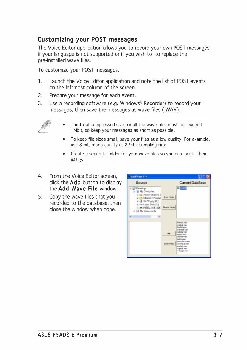
ASUS P5AD2-E PremiumASUS P5AD2-E PremiumASUS P5AD2-E PremiumASUS P5AD2-E PremiumASUS P5AD2-E Premium 3 - 73 - 73 - 73 - 73 - 7
Customizing your POST messagesCustomizing your POST messagesCustomizing your POST messagesCustomizing your POST messagesCustomizing your POST messages
The Voice Editor application allows you to record your own POST messagesif your language is not supported or if you wish to to replace thepre-installed wave files.
To customize your POST messages.
1. Launch the Voice Editor application and note the list of POST eventson the leftmost column of the screen.
2. Prepare your message for each event.
3. Use a recording software (e.g. Windows® Recorder) to record yourmessages, then save the messages as wave files (.WAV).
4. From the Voice Editor screen,click the Add Add Add Add Add button to displaythe Add Wave F i le Add Wave F i le Add Wave F i le Add Wave F i le Add Wave F i le window.
5. Copy the wave files that yourecorded to the database, thenclose the window when done.
• The total compressed size for all the wave files must not exceed1Mbit, so keep your messages as short as possible.
• To keep file sizes small, save your files at a low quality. For example,use 8-bit, mono quality at 22Khz sampling rate.
• Create a separate folder for your wave files so you can locate themeasily.
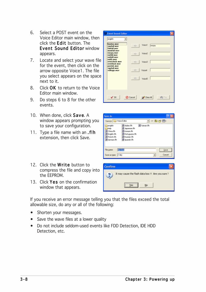
3 - 83 - 83 - 83 - 83 - 8 Chapter 3 : Power ing upChapter 3 : Power ing upChapter 3 : Power ing upChapter 3 : Power ing upChapter 3 : Power ing up
If you receive an error message telling you that the files exceed the totalallowable size, do any or all of the following:
• Shorten your messages.
• Save the wave files at a lower quality
• Do not include seldom-used events like FDD Detection, IDE HDDDetection, etc.
6. Select a POST event on theVoice Editor main window, thenclick the Ed i t Ed i t Ed i t Ed i t Ed i t button. TheEvent Sound EditorEvent Sound EditorEvent Sound EditorEvent Sound EditorEvent Sound Editor windowappears.
7. Locate and select your wave filefor the event, then click on thearrow opposite Voice1. The fileyou select appears on the spacenext to it.
8. Click OK OK OK OK OK to return to the VoiceEditor main window.
9. Do steps 6 to 8 for the otherevents.
10. When done, click SaveSaveSaveSaveSave. Awindow appears prompting youto save your configuration.
11. Type a file name with an . f l h. f l h. f l h. f l h. f l hextension, then click Save.
12. Click the Wr i te Wr i te Wr i te Wr i te Wr i te button tocompress the file and copy intothe EEPROM.
13. Click Yes Yes Yes Yes Yes on the confirmationwindow that appears.

4BIOS setup
This chapter tells how to changethe system settings through the BIOSSetup menus. Detailed descriptionsof the BIOS parameters are alsoprovided.

ASUS P5AD2-E PremiumASUS P5AD2-E PremiumASUS P5AD2-E PremiumASUS P5AD2-E PremiumASUS P5AD2-E Premium
Chapter summary 44.1 Managing and updating your BIOS ........................................ 4-1
4.2 BIOS setup program ........................................................... 4-11
4.3 Main menu .......................................................................... 4-14
4.4 Advanced menu .................................................................. 4-19
4.5 Power menu ........................................................................ 4-33
4.6 Boot menu .......................................................................... 4-38
4.7 Exit menu ........................................................................... 4-43

ASUS P5AD2-E PremiumASUS P5AD2-E PremiumASUS P5AD2-E PremiumASUS P5AD2-E PremiumASUS P5AD2-E Premium 4 - 14 - 14 - 14 - 14 - 1
4.1 Managing and updating your BIOS
The following utilities allow you to manage and update the motherboardBasic Input/Output System (BIOS) setup.
1. ASUS AFUDOS ASUS AFUDOS ASUS AFUDOS ASUS AFUDOS ASUS AFUDOS (Updates the BIOS in DOS mode using a bootablefloppy disk.)
2. ASUS CrashFree BIOS 2 ASUS CrashFree BIOS 2 ASUS CrashFree BIOS 2 ASUS CrashFree BIOS 2 ASUS CrashFree BIOS 2 (Updates the BIOS using a bootablefloppy disk or the motherboard support CD when the BIOS file fails orgets corrupted.)
3. ASUS EZ F lash ASUS EZ F lash ASUS EZ F lash ASUS EZ F lash ASUS EZ F lash (Updates the BIOS in DOS mode using a floppy diskor the motherboard support CD.)
4. ASUS Update ASUS Update ASUS Update ASUS Update ASUS Update (Updates the BIOS in Windows® environment.)
Refer to the corresponding sections for details on these utilities.
4.1.14.1.14.1.14.1.14.1.1 Creating a bootable floppy diskCreating a bootable floppy diskCreating a bootable floppy diskCreating a bootable floppy diskCreating a bootable floppy disk
1. Do either one of the following to create a bootable floppy disk.
DOS environment
a. Insert a 1.44MB floppy disk into the drive.
b. At the DOS prompt, type format A:/S then press <Enter>.
Windows® XP environment
a. Insert a 1.44 MB floppy disk to the floppy disk drive.
b. Click Start Start Start Start Start from the Windows® desktop, then select M yM yM yM yM yComputerComputerComputerComputerComputer.
c. Select the 3 1/2 Floppy Drive icon.
d. Click F i l e F i l e F i l e F i l e F i l e from the menu, then select FormatFormatFormatFormatFormat. A Format 3 1/2Format 3 1/2Format 3 1/2Format 3 1/2Format 3 1/2Floppy D iskF loppy D iskF loppy D iskF loppy D iskF loppy D isk window appears.
e. WindowsWindowsWindowsWindowsWindows®®®®® XP users : XP users : XP users : XP users : XP users : Select Create an MS-DOS startupCreate an MS-DOS startupCreate an MS-DOS startupCreate an MS-DOS startupCreate an MS-DOS startupd i sk d i sk d i sk d i sk d i sk from the format options field, then click Sta r tSta r tSta r tSta r tSta r t.
Save a copy of the original motherboard BIOS file to a bootable floppydisk in case you need to restore the BIOS in the future. Copy the originalmotherboard BIOS using the ASUS Update or AFUDOS utilities.
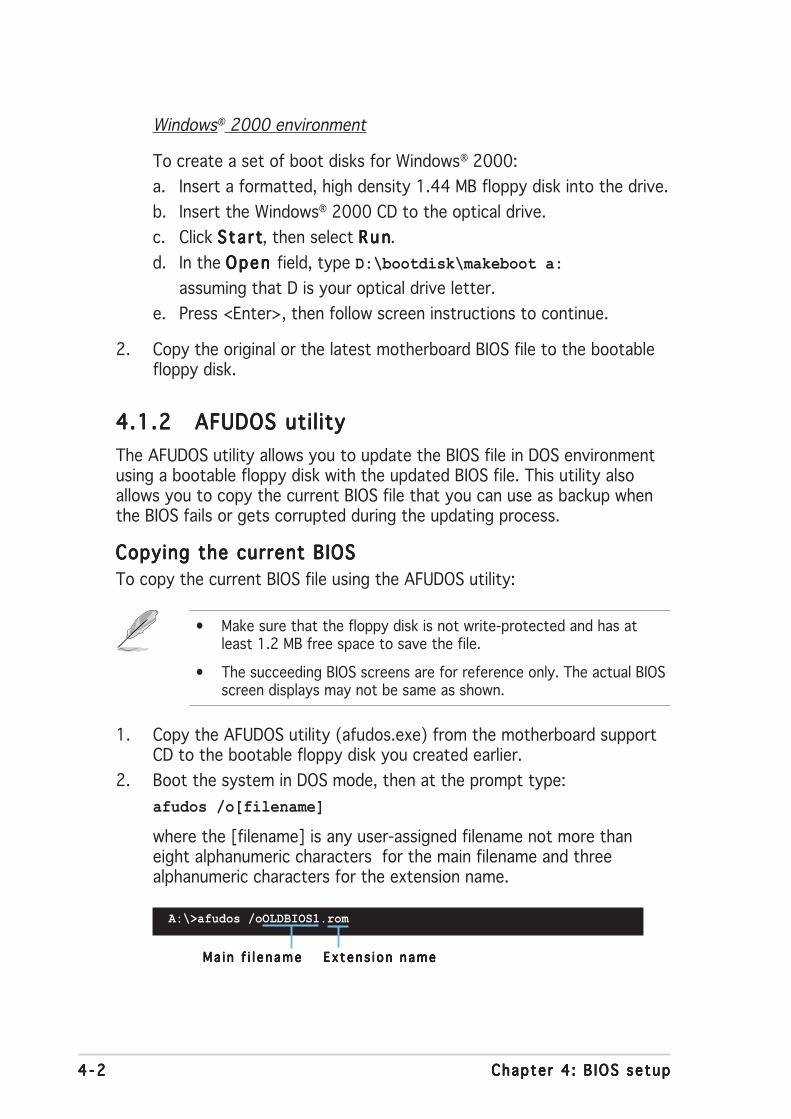
4 - 24 - 24 - 24 - 24 - 2 Chapter 4 : B IOS setupChapter 4 : B IOS setupChapter 4 : B IOS setupChapter 4 : B IOS setupChapter 4 : B IOS setup
4.1.24.1.24.1.24.1.24.1.2 AFUDOS utilityAFUDOS utilityAFUDOS utilityAFUDOS utilityAFUDOS utility
The AFUDOS utility allows you to update the BIOS file in DOS environmentusing a bootable floppy disk with the updated BIOS file. This utility alsoallows you to copy the current BIOS file that you can use as backup whenthe BIOS fails or gets corrupted during the updating process.
Copying the current BIOSCopying the current BIOSCopying the current BIOSCopying the current BIOSCopying the current BIOS
To copy the current BIOS file using the AFUDOS utility:
Windows® 2000 environment
To create a set of boot disks for Windows® 2000:
a. Insert a formatted, high density 1.44 MB floppy disk into the drive.
b. Insert the Windows® 2000 CD to the optical drive.
c. Click Sta r tSta r tSta r tSta r tSta r t, then select R unRunRunRunRun.
d. In the Open Open Open Open Open field, type D:\bootdisk\makeboot a:
assuming that D is your optical drive letter.
e. Press <Enter>, then follow screen instructions to continue.
2. Copy the original or the latest motherboard BIOS file to the bootablefloppy disk.
Ma i n f i l e nameMa i n f i l e nameMa i n f i l e nameMa i n f i l e nameMa i n f i l e name Ex tens i on nameEx tens i on nameEx tens i on nameEx tens i on nameEx tens i on name
1. Copy the AFUDOS utility (afudos.exe) from the motherboard supportCD to the bootable floppy disk you created earlier.
2. Boot the system in DOS mode, then at the prompt type:
afudos /o[filename]
where the [filename] is any user-assigned filename not more thaneight alphanumeric characters for the main filename and threealphanumeric characters for the extension name.
A:\>afudos /oOLDBIOS1.rom
• Make sure that the floppy disk is not write-protected and has atleast 1.2 MB free space to save the file.
• The succeeding BIOS screens are for reference only. The actual BIOSscreen displays may not be same as shown.
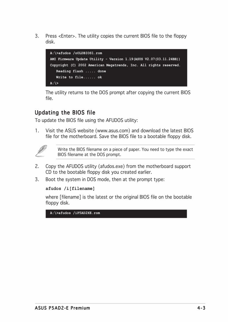
ASUS P5AD2-E PremiumASUS P5AD2-E PremiumASUS P5AD2-E PremiumASUS P5AD2-E PremiumASUS P5AD2-E Premium 4 - 34 - 34 - 34 - 34 - 3
The utility returns to the DOS prompt after copying the current BIOSfile.
3. Press <Enter>. The utility copies the current BIOS file to the floppydisk.
A:\>afudos /oOLDBIOS1.rom
AMI Firmware Update Utility - Version 1.19(ASUS V2.07(03.11.24BB))
Copyright (C) 2002 American Megatrends, Inc. All rights reserved.
Reading flash ..... done
Write to file...... ok
A:\>
2. Copy the AFUDOS utility (afudos.exe) from the motherboard supportCD to the bootable floppy disk you created earlier.
3. Boot the system in DOS mode, then at the prompt type:
afudos /i[filename]
where [filename] is the latest or the original BIOS file on the bootablefloppy disk.
Updating the BIOS fi leUpdating the BIOS fi leUpdating the BIOS fi leUpdating the BIOS fi leUpdating the BIOS fi le
To update the BIOS file using the AFUDOS utility:
1. Visit the ASUS website (www.asus.com) and download the latest BIOSfile for the motherboard. Save the BIOS file to a bootable floppy disk.
A:\>afudos /iP5AD2XE.rom
Write the BIOS filename on a piece of paper. You need to type the exactBIOS filename at the DOS prompt.
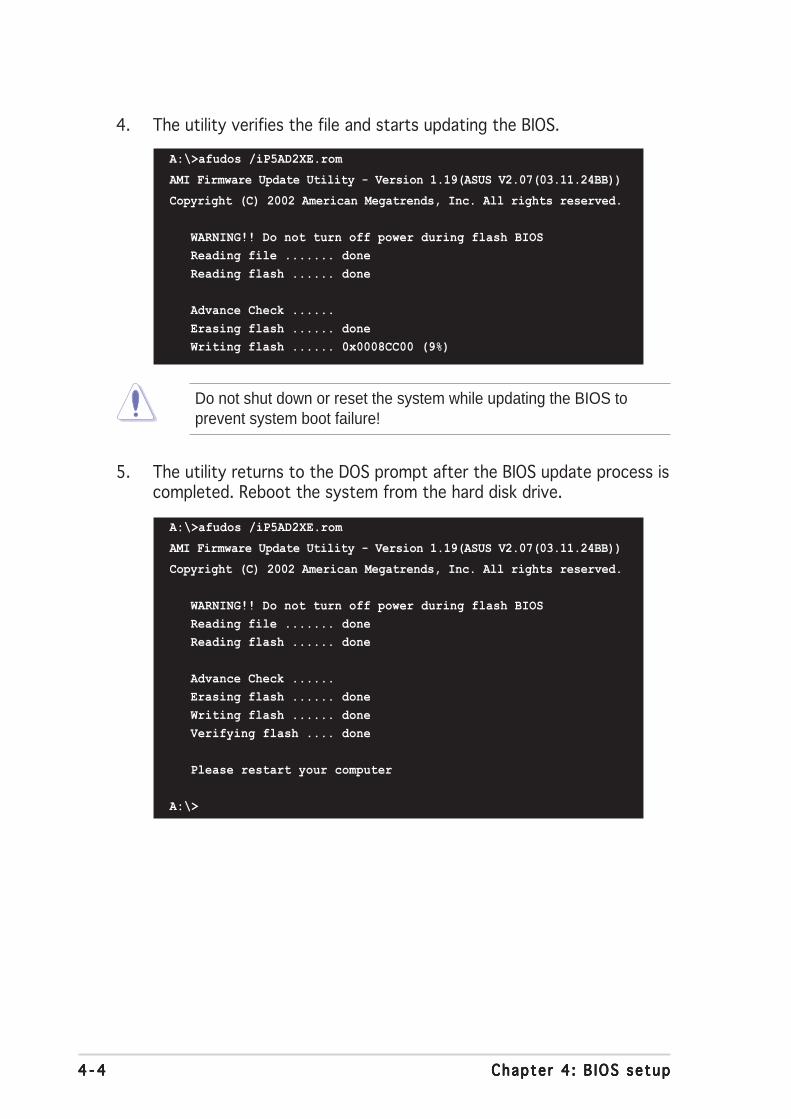
4 - 44 - 44 - 44 - 44 - 4 Chapter 4 : B IOS setupChapter 4 : B IOS setupChapter 4 : B IOS setupChapter 4 : B IOS setupChapter 4 : B IOS setup
5. The utility returns to the DOS prompt after the BIOS update process iscompleted. Reboot the system from the hard disk drive.
A:\>afudos /iP5AD2XE.rom
AMI Firmware Update Utility - Version 1.19(ASUS V2.07(03.11.24BB))
Copyright (C) 2002 American Megatrends, Inc. All rights reserved.
WARNING!! Do not turn off power during flash BIOS
Reading file ....... done
Reading flash ...... done
Advance Check ......
Erasing flash ...... done
Writing flash ...... 0x0008CC00 (9%)
4. The utility verifies the file and starts updating the BIOS.
Do not shut down or reset the system while updating the BIOS toprevent system boot failure!
A:\>afudos /iP5AD2XE.rom
AMI Firmware Update Utility - Version 1.19(ASUS V2.07(03.11.24BB))
Copyright (C) 2002 American Megatrends, Inc. All rights reserved.
WARNING!! Do not turn off power during flash BIOS
Reading file ....... done
Reading flash ...... done
Advance Check ......
Erasing flash ...... done
Writing flash ...... done
Verifying flash .... done
Please restart your computer
A:\>

ASUS P5AD2-E PremiumASUS P5AD2-E PremiumASUS P5AD2-E PremiumASUS P5AD2-E PremiumASUS P5AD2-E Premium 4 - 54 - 54 - 54 - 54 - 5
4.1.34.1.34.1.34.1.34.1.3 ASUS CrashFree BIOS 2 utilityASUS CrashFree BIOS 2 utilityASUS CrashFree BIOS 2 utilityASUS CrashFree BIOS 2 utilityASUS CrashFree BIOS 2 utility
The ASUS CrashFree BIOS 2 is an auto recovery tool that allows you torestore the BIOS file when it fails or gets corrupted during the updatingprocess. You can update a corrupted BIOS file using the motherboardsupport CD or the floppy disk that contains the updated BIOS file.
Recovering the BIOS from a floppy diskRecovering the BIOS from a floppy diskRecovering the BIOS from a floppy diskRecovering the BIOS from a floppy diskRecovering the BIOS from a floppy disk
To recover the BIOS from a floppy disk:
1. Turn on the system.
2. Insert the floppy disk with the original or updated BIOS file to thefloppy disk drive.
3. The utility displays the following message and automatically checksthe floppy disk for the original or updated BIOS file.
Bad BIOS checksum. Starting BIOS recovery...
Checking for floppy...
4. Restart the system after the utility completes the updating process.
Bad BIOS checksum. Starting BIOS recovery...
Checking for floppy...
Floppy found!
Reading file “P5AD2XE.ROM”. Completed.
Start flashing...
When found, the utility reads the BIOS file and starts flashing thecorrupted BIOS file.
DO NOT shut down or reset the system while updating the BIOS! Doingso can cause system boot failure!
• Prepare the motherboard support CD or the floppy disk containingthe updated motherboard BIOS before using this utility.
• Make sure that you rename the original or updated BIOS file in thefloppy disk to P5AD2XE .ROMP5AD2XE .ROMP5AD2XE .ROMP5AD2XE .ROMP5AD2XE .ROM.

4 - 64 - 64 - 64 - 64 - 6 Chapter 4 : B IOS setupChapter 4 : B IOS setupChapter 4 : B IOS setupChapter 4 : B IOS setupChapter 4 : B IOS setup
The recovered BIOS may not be the latest BIOS version for thismotherboard. Visit the ASUS website (www.asus.com) to download thelatest BIOS file.
Recovering the BIOS from the support CDRecovering the BIOS from the support CDRecovering the BIOS from the support CDRecovering the BIOS from the support CDRecovering the BIOS from the support CD
To recover the BIOS from the support CD:
1. Remove any floppy disk from the floppy disk drive, then turn on thesystem.
2. Insert the support CD to the optical drive.
3. The utility displays the following message and automatically checksthe floppy disk for the original or updated BIOS file.
4. Restart the system after the utility completes the updating process.
DO NOT shut down or reset the system while updating the BIOS! Doingso can cause system boot failure!
Bad BIOS checksum. Starting BIOS recovery...
Checking for floppy...
Floppy not found!
Checking for CD-ROM...
CD-ROM found!
Reading file “P5AD2XE.ROM”. Completed.
Start flashing...
When no floppy disk is found, the utility automatically checks theoptical drive for the original or updated BIOS file. The utility thenupdates the corrupted BIOS file.
Bad BIOS checksum. Starting BIOS recovery...
Checking for floppy...
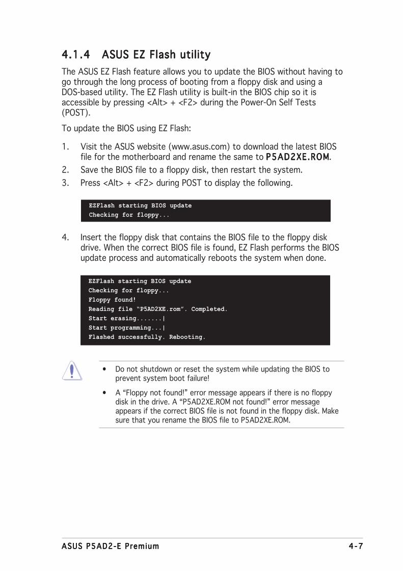
ASUS P5AD2-E PremiumASUS P5AD2-E PremiumASUS P5AD2-E PremiumASUS P5AD2-E PremiumASUS P5AD2-E Premium 4 - 74 - 74 - 74 - 74 - 7
4.1.44.1.44.1.44.1.44.1.4 ASUS EZ Flash utilityASUS EZ Flash utilityASUS EZ Flash utilityASUS EZ Flash utilityASUS EZ Flash utility
The ASUS EZ Flash feature allows you to update the BIOS without having togo through the long process of booting from a floppy disk and using aDOS-based utility. The EZ Flash utility is built-in the BIOS chip so it isaccessible by pressing <Alt> + <F2> during the Power-On Self Tests(POST).
To update the BIOS using EZ Flash:
1. Visit the ASUS website (www.asus.com) to download the latest BIOSfile for the motherboard and rename the same to P5AD2XE.ROMP5AD2XE.ROMP5AD2XE.ROMP5AD2XE.ROMP5AD2XE.ROM.
2. Save the BIOS file to a floppy disk, then restart the system.
3. Press <Alt> + <F2> during POST to display the following.
EZFlash starting BIOS update
Checking for floppy...
4. Insert the floppy disk that contains the BIOS file to the floppy diskdrive. When the correct BIOS file is found, EZ Flash performs the BIOSupdate process and automatically reboots the system when done.
EZFlash starting BIOS update
Checking for floppy...
Floppy found!
Reading file “P5AD2XE.rom”. Completed.
Start erasing.......|
Start programming...|
Flashed successfully. Rebooting.
• Do not shutdown or reset the system while updating the BIOS toprevent system boot failure!
• A “Floppy not found!” error message appears if there is no floppydisk in the drive. A “P5AD2XE.ROM not found!” error messageappears if the correct BIOS file is not found in the floppy disk. Makesure that you rename the BIOS file to P5AD2XE.ROM.

4 - 84 - 84 - 84 - 84 - 8 Chapter 4 : B IOS setupChapter 4 : B IOS setupChapter 4 : B IOS setupChapter 4 : B IOS setupChapter 4 : B IOS setup
Install ing ASUS UpdateInstall ing ASUS UpdateInstall ing ASUS UpdateInstall ing ASUS UpdateInstall ing ASUS Update
To install ASUS Update:
1. Place the support CD in the optical drive. The Dr ivers Dr ivers Dr ivers Dr ivers Dr ivers menu appears.
2. Click the Ut i l i t ies Ut i l i t ies Ut i l i t ies Ut i l i t ies Ut i l i t ies tab, then click Insta l l ASUS UpdateInsta l l ASUS UpdateInsta l l ASUS UpdateInsta l l ASUS UpdateInsta l l ASUS UpdateVX.XX.XXVX.XX.XXVX.XX.XXVX.XX.XXVX.XX.XX. See page 5-4 for the Ut i l i t ies Ut i l i t ies Ut i l i t ies Ut i l i t ies Ut i l i t ies screen menu.
3. The ASUS Update utility is copied to your system.
4.1.54.1.54.1.54.1.54.1.5 ASUS Update utilityASUS Update utilityASUS Update utilityASUS Update utilityASUS Update utility
The ASUS Update is a utility that allows you to manage, save, and updatethe motherboard BIOS in Windows® environment. The ASUS Update utilityallows you to:
• Save the current BIOS file
• Download the latest BIOS file from the Internet
• Update the BIOS from an updated BIOS file
• Update the BIOS directly from the Internet, and
• View the BIOS version information.
This utility is available in the support CD that comes with the motherboardpackage.
ASUS Update requires an Internet connection either through a networkor an Internet Service Provider (ISP).
Quit all Windows® applications before you update the BIOS using thisutility.

ASUS P5AD2-E PremiumASUS P5AD2-E PremiumASUS P5AD2-E PremiumASUS P5AD2-E PremiumASUS P5AD2-E Premium 4 - 94 - 94 - 94 - 94 - 9
3. Select the ASUS FTP sitenearest you to avoid networktraffic, or click Auto Se lectAuto Se lectAuto Se lectAuto Se lectAuto Se lect.Click NextNextNextNextNext.
Updating the BIOS through the InternetUpdating the BIOS through the InternetUpdating the BIOS through the InternetUpdating the BIOS through the InternetUpdating the BIOS through the Internet
To update the BIOS through the Internet:
1. Launch the ASUS Update utility from the Windows® desktop by clickingStart Start Start Start Start > Programs Programs Programs Programs Programs > ASUS ASUS ASUS ASUS ASUS > ASUSUpdate ASUSUpdate ASUSUpdate ASUSUpdate ASUSUpdate > ASUSUpdateASUSUpdateASUSUpdateASUSUpdateASUSUpdate. TheASUS Update main window appears.
2. Select Update B IOS fromUpdate B IOS fromUpdate B IOS fromUpdate B IOS fromUpdate B IOS fromthe Internet the Internet the Internet the Internet the Internet option from thedrop-down menu, then clickNextNextNextNextNext.
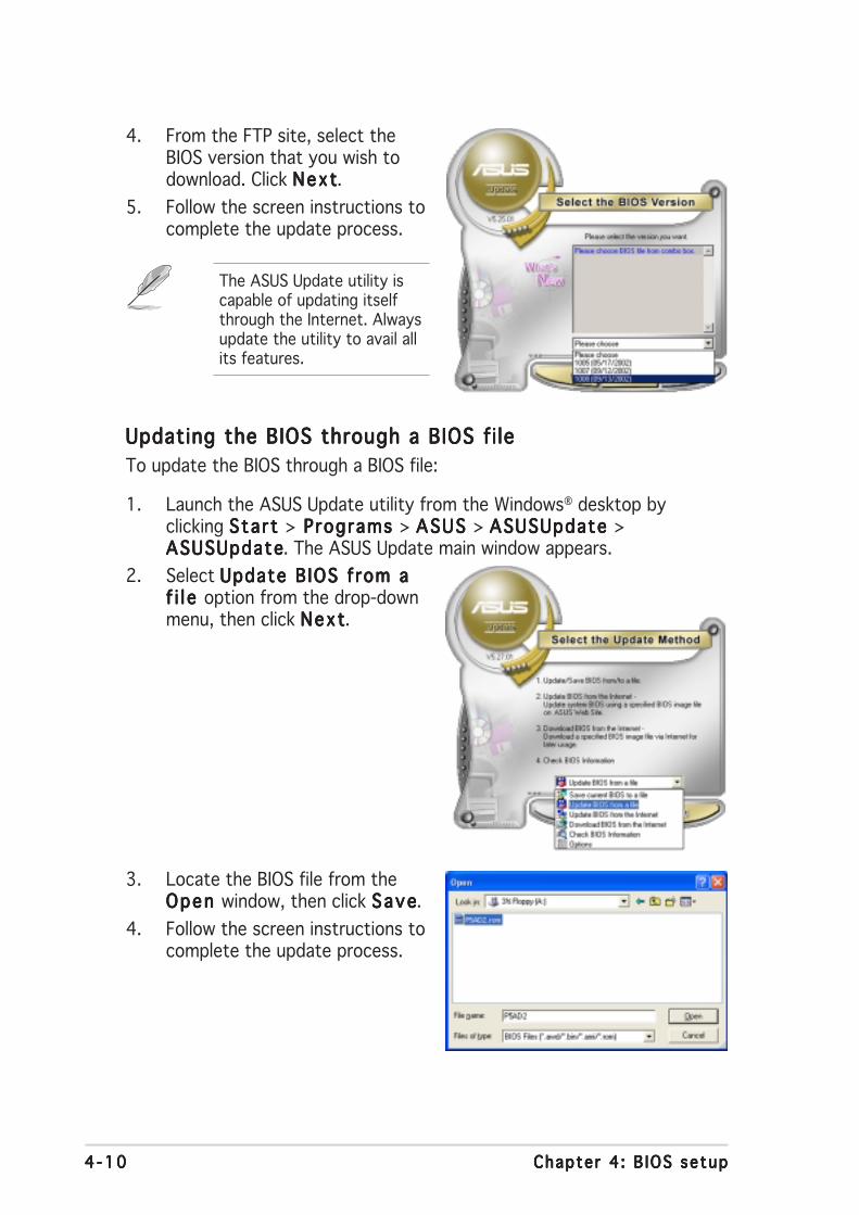
4 -104 -104 -104 -104 -10 Chapter 4 : B IOS setupChapter 4 : B IOS setupChapter 4 : B IOS setupChapter 4 : B IOS setupChapter 4 : B IOS setup
Updating the BIOS through a BIOS fi leUpdating the BIOS through a BIOS fi leUpdating the BIOS through a BIOS fi leUpdating the BIOS through a BIOS fi leUpdating the BIOS through a BIOS fi le
To update the BIOS through a BIOS file:
1. Launch the ASUS Update utility from the Windows® desktop byclicking Start Start Start Start Start > Programs Programs Programs Programs Programs > ASUS ASUS ASUS ASUS ASUS > ASUSUpdate ASUSUpdate ASUSUpdate ASUSUpdate ASUSUpdate >ASUSUpdateASUSUpdateASUSUpdateASUSUpdateASUSUpdate. The ASUS Update main window appears.
2. Select Update B IOS from aUpdate B IOS from aUpdate B IOS from aUpdate B IOS from aUpdate B IOS from af i l e f i l e f i l e f i l e f i l e option from the drop-downmenu, then click NextNextNextNextNext.
4. From the FTP site, select theBIOS version that you wish todownload. Click NextNextNextNextNext.
5. Follow the screen instructions tocomplete the update process.
The ASUS Update utility iscapable of updating itselfthrough the Internet. Alwaysupdate the utility to avail allits features.
3. Locate the BIOS file from theOpen Open Open Open Open window, then click SaveSaveSaveSaveSave.
4. Follow the screen instructions tocomplete the update process.
ASUS P5AD2-E PremiumASUS P5AD2-E PremiumASUS P5AD2-E PremiumASUS P5AD2-E PremiumASUS P5AD2-E Premium 4 -114 -114 -114 -114 -11
4.2 BIOS setup program
This motherboard supports a programmable firmware chip that you canupdate using the provided utility described in section “4.1 Managing andupdating your BIOS.”
Use the BIOS Setup program when you are installing a motherboard,reconfiguring your system, or prompted to “Run Setup”. This sectionexplains how to configure your system using this utility.
Even if you are not prompted to use the Setup program, you can changethe configuration of your computer in the future. For example, you canenable the security password feature or change the power managementsettings. This requires you to reconfigure your system using the BIOSSetup program so that the computer can recognize these changes andrecord them in the CMOS RAM of the firmware hub.
The firmware hub on the motherboard stores the Setup utility. When youstart up the computer, the system provides you with the opportunity torun this program. Press <Del> during the Power-On-Self-Test (POST) toenter the Setup utility; otherwise, POST continues with its test routines.
If you wish to enter Setup after POST, restart the system by pressing<Ctrl+Alt+Delete>, or by pressing the reset button on the system chassis.You can also restart by turning the system off and then back on. Do thislast option only if the first two failed.
The Setup program is designed to make it as easy to use as possible. Beinga menu-driven program, it lets you scroll through the various sub-menusand make your selections from the available options using the navigationkeys.
• The default BIOS settings for this motherboard apply for mostconditions to ensure optimum performance. If the system becomesunstable after changing any BIOS settings, load the default settingsto ensure system compatibility and stability. Select the L o a dL o a dL o a dL o a dL o a dDefau l t Sett ingsDefau l t Sett ingsDefau l t Sett ingsDefau l t Sett ingsDefau l t Sett ings item under the Exit Menu. See section “4.7 ExitMenu.”
• The BIOS setup screens shown in this section are for referencepurposes only, and may not exactly match what you see on yourscreen.
• Visit the ASUS website (www.asus.com) to download the latest BIOSfile for this motherboard.

4 -124 -124 -124 -124 -12 Chapter 4 : B IOS setupChapter 4 : B IOS setupChapter 4 : B IOS setupChapter 4 : B IOS setupChapter 4 : B IOS setup
4.2.24.2.24.2.24.2.24.2.2 Menu barMenu barMenu barMenu barMenu bar
The menu bar on top of the screen has the following main items:
Ma inMa inMa inMa inMa in For changing the basic system configuration
AdvancedAdvancedAdvancedAdvancedAdvanced For changing the advanced system settings
PowerPowerPowerPowerPower For changing the advanced power management (APM)configuration
BootBootBootBootBoot For changing the system boot configuration
Ex i tEx i tEx i tEx i tEx i t For selecting the exit options and loading defaultsettings
To select an item on the menu bar, press the right or left arrow key on thekeyboard until the desired item is highlighted.
4.2.34.2.34.2.34.2.34.2.3 Navigation keysNavigation keysNavigation keysNavigation keysNavigation keys
At the bottom right corner of a menu screen are the navigation keys forthat particular menu. Use the navigation keys to select items in the menuand change the settings.
4.2.14.2.14.2.14.2.14.2.1 BIOS menu screenBIOS menu screenBIOS menu screenBIOS menu screenBIOS menu screen
Some of the navigation keys differ from one screen to another.
System Time [11:10:19]System Date [Thu 03/27/2003]Legacy Diskette A [1.44M, 3.5 in]Language [English]
Primary IDE Master :[ST320413A] Primary IDE Slave :[ASUS CD-S340] Secondary IDE Master :[Not Detected] Secondary IDE Slave :[Not Detected] Third IDE Master :[Not Detected] Fourth IDE Master :[Not Detected] IDE Configuration
System Information
Use [ENTER], [TAB]or [SHIFT-TAB] toselect a field.
Use [+] or [-] toconfigure system time.
Select Screen Select Item+- Change FieldTab Select FieldF1 General HelpF10 Save and ExitESC Exit
Nav iga t i on keysNav i ga t i on keysNav i ga t i on keysNav i ga t i on keysNav i ga t i on keys
Gene r a l he l pGene r a l he l pGene r a l he l pGene r a l he l pGene r a l he l pMenu ba rMenu ba rMenu ba rMenu ba rMenu ba r
Sub -menu i t emsSub -menu i t emsSub -menu i t emsSub -menu i t emsSub -menu i t ems
Con f i gu ra t i on f i e l d sCon f i gu ra t i on f i e l d sCon f i gu ra t i on f i e l d sCon f i gu ra t i on f i e l d sCon f i gu ra t i on f i e l d sMenu i t emsMenu i t emsMenu i t emsMenu i t emsMenu i t ems

ASUS P5AD2-E PremiumASUS P5AD2-E PremiumASUS P5AD2-E PremiumASUS P5AD2-E PremiumASUS P5AD2-E Premium 4 -134 -134 -134 -134 -13
4.2.44.2.44.2.44.2.44.2.4 Menu itemsMenu itemsMenu itemsMenu itemsMenu items
The highlighted item on the menu bardisplays the specific items for thatmenu. For example, selecting Ma inMa inMa inMa inMa inshows the Main menu items.
The other items (Advanced, Power,Boot, and Exit) on the menu bar havetheir respective menu items.
4.2.54.2.54.2.54.2.54.2.5 Sub-menu itemsSub-menu itemsSub-menu itemsSub-menu itemsSub-menu items
A solid triangle before each item on any menu screen means that the iteamhas a sub-menu. To display the sub-menu, select the item and press<Enter>.
4.2.64.2.64.2.64.2.64.2.6 Configuration fieldsConfiguration fieldsConfiguration fieldsConfiguration fieldsConfiguration fields
These fields show the values for the menu items. If an item is user-configurable, you can change the value of the field opposite the item. Youcannot select an item that is not user-configurable.
A configurable field is enclosed in brackets, and is highlighted whenselected. To change the value of a field, select it then press <Enter> todisplay a list of options. Refer to “4.2.7 Pop-up window.”
4.2.74.2.74.2.74.2.74.2.7 Pop-up windowPop-up windowPop-up windowPop-up windowPop-up window
Select a menu item then press <Enter> to display a pop-up window withthe configuration options for that item.
4.2.84.2.84.2.84.2.84.2.8 Scroll barScroll barScroll barScroll barScroll bar
A scroll bar appears on the right sideof a menu screen when there are itemsthat do not fit on the screen. Press theUp/Down arrow keys or <Page Up> /<Page Down> keys to display the otheritems on the screen.
4.2.94.2.94.2.94.2.94.2.9 General helpGeneral helpGeneral helpGeneral helpGeneral help
At the top right corner of the menuscreen is a brief description of theselected item.
System Time [11:10:19]System Date [Thu 03/27/2003]Legacy Diskette A [1.44M, 3.5 in]Language [English]
Primary IDE Master :[ST320413A] Primary IDE Slave :[ASUS CD-S340] Secondary IDE Master :[Not Detected] Secondary IDE Slave :[Not Detected] Third IDE Master :[Not Detected] Fourth IDE Master :[Not Detected] IDE Configuration
System Information
Use [ENTER], [TAB]or [SHIFT-TAB] toselect a field.
Use [+] or [-] toconfigure system time.
Select Screen Select Item+- Change FieldTab Select FieldF1 General HelpF10 Save and ExitESC Exit
Ma in menu i t emsMa i n menu i t emsMa i n menu i t emsMa i n menu i t emsMa i n menu i t ems
Sc ro l l b a rSc ro l l b a rSc ro l l b a rSc ro l l b a rSc ro l l b a r
Select Screen Select Item+- Change OptionF1 General HelpF10 Save and ExitESC Exit
Advanced Chipset settings
WARNING: Setting wrong values in the sections below may cause system to malfunction.
Configure DRAM Timing by SPD [Enabled]Memory Acceleration Mode [Auto]DRAM Idle Timer [Auto]DRAm Refresh Rate [Auto]
Graphic Adapter Priority [AGP/PCI]Graphics Aperture Size [ 64 MB]Spread Spectrum [Enabled]
ICH Delayed Transaction [Enabled]
MPS Revision [1.4]
Pop -up w i ndowPop -up w i ndowPop -up w i ndowPop -up w i ndowPop -up w i ndow
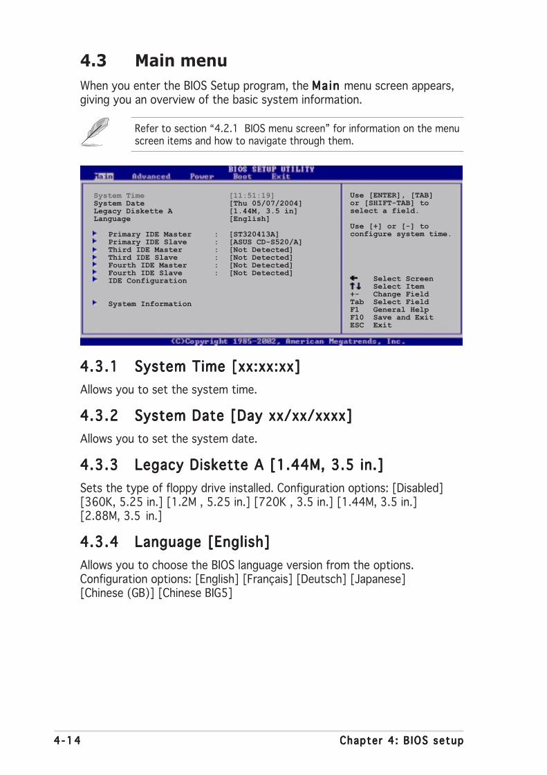
4 -144 -144 -144 -144 -14 Chapter 4 : B IOS setupChapter 4 : B IOS setupChapter 4 : B IOS setupChapter 4 : B IOS setupChapter 4 : B IOS setup
4.3 Main menu
When you enter the BIOS Setup program, the Ma in Ma in Ma in Ma in Ma in menu screen appears,giving you an overview of the basic system information.
4.3.14.3.14.3.14.3.14.3.1 System Time [xx:xx:xx]System Time [xx:xx:xx]System Time [xx:xx:xx]System Time [xx:xx:xx]System Time [xx:xx:xx]
Allows you to set the system time.
4.3.24.3.24.3.24.3.24.3.2 System Date [Day xx/xx/xxxx]System Date [Day xx/xx/xxxx]System Date [Day xx/xx/xxxx]System Date [Day xx/xx/xxxx]System Date [Day xx/xx/xxxx]
Allows you to set the system date.
4.3.34.3.34.3.34.3.34.3.3 Legacy Diskette A [1.44M, 3.5 in.]Legacy Diskette A [1.44M, 3.5 in.]Legacy Diskette A [1.44M, 3.5 in.]Legacy Diskette A [1.44M, 3.5 in.]Legacy Diskette A [1.44M, 3.5 in.]
Sets the type of floppy drive installed. Configuration options: [Disabled][360K, 5.25 in.] [1.2M , 5.25 in.] [720K , 3.5 in.] [1.44M, 3.5 in.][2.88M, 3.5 in.]
4.3.44.3.44.3.44.3.44.3.4 Language [English]Language [English]Language [English]Language [English]Language [English]
Allows you to choose the BIOS language version from the options.Configuration options: [English] [Français] [Deutsch] [Japanese][Chinese (GB)] [Chinese BIG5]
Refer to section “4.2.1 BIOS menu screen” for information on the menuscreen items and how to navigate through them.
Use [ENTER], [TAB]or [SHIFT-TAB] toselect a field.
Use [+] or [-] toconfigure system time.
Select Screen Select Item+- Change FieldTab Select FieldF1 General HelpF10 Save and ExitESC Exit
System Time [11:51:19]System Date [Thu 05/07/2004]Legacy Diskette A [1.44M, 3.5 in]Language [English]
Primary IDE Master : [ST320413A]Primary IDE Slave : [ASUS CD-S520/A]Third IDE Master : [Not Detected]Third IDE Slave : [Not Detected]Fourth IDE Master : [Not Detected]Fourth IDE Slave : [Not Detected]IDE Configuration
System Information

ASUS P5AD2-E PremiumASUS P5AD2-E PremiumASUS P5AD2-E PremiumASUS P5AD2-E PremiumASUS P5AD2-E Premium 4 -154 -154 -154 -154 -15
4.3.54.3.54.3.54.3.54.3.5 Primary, Third and Fourth IDE Master/SlavePrimary, Third and Fourth IDE Master/SlavePrimary, Third and Fourth IDE Master/SlavePrimary, Third and Fourth IDE Master/SlavePrimary, Third and Fourth IDE Master/Slave
The BIOS automatically detects the connected IDE devices. There is aseparate sub-menu for each IDE device. Select a device item, then press<Enter> to display the IDE device information.
The BIOS automatically detects the values opposite the dimmed items(Device, Vendor, Size, LBA Mode, Block Mode, PIO Mode, Async DMA, UltraDMA, and SMART monitoring). These values are not user-configurable.These items show N/A if no IDE device is installed in the system.
Type [Auto]Type [Auto]Type [Auto]Type [Auto]Type [Auto]
Selects the type of IDE drive. Setting to [Auto] allows automatic selectionof the appropriate IDE device type. Select [CDROM] if you are specificallyconfiguring a CD-ROM drive. Select [ARMD] (ATAPI Removable MediaDevice) if your device is either a ZIP, LS-120, or MO drive.Configuration options: [Not Installed] [Auto] [CDROM] [ARMD]
LBA/Large Mode [Auto]LBA/Large Mode [Auto]LBA/Large Mode [Auto]LBA/Large Mode [Auto]LBA/Large Mode [Auto]
Enables or disables the LBA mode. Setting to [Auto] enables the LBA modeif the device supports this mode, and if the device was not previouslyformatted with LBA mode disabled. Configuration options: [Disabled][Auto]
Block (Multi-sector Transfer) [Auto]Block (Multi-sector Transfer) [Auto]Block (Multi-sector Transfer) [Auto]Block (Multi-sector Transfer) [Auto]Block (Multi-sector Transfer) [Auto]
Enables or disables data multi-sectors transfers. When set to [Auto], thedata transfer from and to the device occurs multiple sectors at a time ifthe device supports multi-sector transfer feature. When set to [Disabled],the data transfer from and to the device occurs one sector at a time.Configuration options: [Disabled] [Auto]
Select the typeof device connectedto the system.
Select Screen Select Item+- Change OptionF1 General HelpF10 Save and ExitESC Exit
Primary IDE Master
Device : Hard DiskVendor : ST320413ASize : 20.0GBLBA Mode : SupportedBlock Mode : 16 SectorsPIO Mode : SupportedAsync DMA : MultiWord DMA-2Ultra DMA : Ultra DMA-5SMART Monitoring: Supported
Type [Auto]LBA/Large Mode [Auto]Block(Multi-sector Transfer) [Auto]PIO Mode [Auto]DMA Mode [Auto]SMART Monitoring [Auto]32Bit Data Transfer [Disabled]

4 -164 -164 -164 -164 -16 Chapter 4 : B IOS setupChapter 4 : B IOS setupChapter 4 : B IOS setupChapter 4 : B IOS setupChapter 4 : B IOS setup
PIO Mode [Auto]PIO Mode [Auto]PIO Mode [Auto]PIO Mode [Auto]PIO Mode [Auto]
Selects the PIO mode.Configuration options: [Auto] [0] [1] [2] [3] [4]
SMART Monitoring [Auto]SMART Monitoring [Auto]SMART Monitoring [Auto]SMART Monitoring [Auto]SMART Monitoring [Auto]
Sets the Smart Monitoring, Analysis, and Reporting Technology.Configuration options: [Auto] [Disabled] [Enabled]
32Bit Data Transfer [Disabled]32Bit Data Transfer [Disabled]32Bit Data Transfer [Disabled]32Bit Data Transfer [Disabled]32Bit Data Transfer [Disabled]
Enables or disables 32-bit data transfer.Configuration options: [Disabled] [Enabled]
4.3.64.3.64.3.64.3.64.3.6 IDE ConfigurationIDE ConfigurationIDE ConfigurationIDE ConfigurationIDE Configuration
The items in this menu allow you to set or change the configurations forthe IDE devices installed in the system. Select an item then press <Enter>if you wish to configure the item.
Configure SATA As [Standard IDE]Configure SATA As [Standard IDE]Configure SATA As [Standard IDE]Configure SATA As [Standard IDE]Configure SATA As [Standard IDE]
Sets the configuration for the Serial ATA connectors supported by theSouthbridge chip.
The AHCI allows the onboard storage driver to enable advanced Serial ATAfeatures that increases storage performance on random workloads byallowing the drive to internally optimize the order of commands.
If you want to create a RAID 0, RAID 1, or the Intel® Matrix StorageTechnology configuration from the Serial ATA hard disk drives, set thisitem to [RAID].
If you want to use the Serial ATA hard disk drives as Parallel ATA physicalstorage devices, set this item to [Standard IDE].
If you want the Serial ATA hard disk drives to use the Advanced HostController Interface (AHCI), set this item to [AHCI]. For details on AHCI, goto: www.intel.com/support/chipsets/imst/sb/CS-012304.htm
www.intel.com/support/chipsets/imst/sb/CS-012305.htm
The SATA controller is set to Native mode when this item is set to [RAID]or [AHCI].
IDE Configuration
Configure SATA As [Standard IDE]Onboard IDE Operate Mode [Enhanced Mode]
Enhanced Mode Support On [S-ATA]
IDE Detect Time Out (Sec) [35]
When in AHCI/RAIDmode SATAcontroller isforced to Nativemode.
ASUS P5AD2-E PremiumASUS P5AD2-E PremiumASUS P5AD2-E PremiumASUS P5AD2-E PremiumASUS P5AD2-E Premium 4 -174 -174 -174 -174 -17
Onboard IDE Operate Mode [Enhanced Mode]Onboard IDE Operate Mode [Enhanced Mode]Onboard IDE Operate Mode [Enhanced Mode]Onboard IDE Operate Mode [Enhanced Mode]Onboard IDE Operate Mode [Enhanced Mode]
Allows selection of the IDE operation mode depending on the installedoperating system (OS). Set to [Enhanced Mode] if you are using native OSincluding Windows® 2000/XP. Configuration options: [Compatible Mode][Enhanced Mode]
Enhanced Mode Support On [S-ATA]
Allows you to use native OS on Serial ATA and Parallel ATA ports. It isrecommend that you do not change the default setting for better OScompatibility. In this setting, you may use legacy OS on the ParallelATA ports only if you do not install any Serial ATA device.
The P-ATA+S-ATA and P-ATA options are for advanced users only. Ifyou set to any of these options and encountered problems, revert tothe default setting S -ATAS-ATAS-ATAS-ATAS-ATA. Configuration options: [P-ATA+S-ATA][S-ATA] [P-ATA]
The Onboard IDE Operate Mode Onboard IDE Operate Mode Onboard IDE Operate Mode Onboard IDE Operate Mode Onboard IDE Operate Mode and its sub-menu items appearonly when the Conf igure SATA As Conf igure SATA As Conf igure SATA As Conf igure SATA As Conf igure SATA As item is set to [Standard IDE].
Onboard Serial-ATA BOOTROOM [Disabled]
Enables or disables the onboard Serial ATA boot ROM. This itemappears only when the Configure SATA As item is set as RAID.Configuration options: [Disabled] [Enabled]
The Onboard Ser ia l -ATA BOOTROM Onboard Ser ia l -ATA BOOTROM Onboard Ser ia l -ATA BOOTROM Onboard Ser ia l -ATA BOOTROM Onboard Ser ia l -ATA BOOTROM appears only when theConf igure SATA As Conf igure SATA As Conf igure SATA As Conf igure SATA As Conf igure SATA As item is set to [RAID].
ALPE and ASP [Disabled]ALPE and ASP [Disabled]ALPE and ASP [Disabled]ALPE and ASP [Disabled]ALPE and ASP [Disabled]
Allows you to enable or disable the Agressive Link Power Management(ALPE) and Aggressive Slumber/Partial (ASP) management features.Configuration options: [Disabled] [Enabled]
AHCI Port 3 Interlock Switch [Disabled]
Enables or disables the Advanced Host Controller Interface (AHCI) Port3 interlock switch. Configuration options: [Disabled] [Enabled]
The ALPE and ASP ALPE and ASP ALPE and ASP ALPE and ASP ALPE and ASP and its sub-menu items appear only when theConf igure SATA As Conf igure SATA As Conf igure SATA As Conf igure SATA As Conf igure SATA As item is set to [AHCI].
IDE Detect Time Out [35]IDE Detect Time Out [35]IDE Detect Time Out [35]IDE Detect Time Out [35]IDE Detect Time Out [35]
Selects the time out value for detecting ATA/ATAPI devices.Configuration options: [0] [5] [10] [15] [20] [25] [30] [35]

4 -184 -184 -184 -184 -18 Chapter 4 : B IOS setupChapter 4 : B IOS setupChapter 4 : B IOS setupChapter 4 : B IOS setupChapter 4 : B IOS setup
4.3.74.3.74.3.74.3.74.3.7 System InformationSystem InformationSystem InformationSystem InformationSystem Information
This menu gives you an overview of the general system specifications. TheBIOS automatically detects the items in this menu.
AMI BIOSAMI BIOSAMI BIOSAMI BIOSAMI BIOS
Displays the auto-detected BIOS information
ProcessorProcessorProcessorProcessorProcessor
Displays the auto-detected CPU specification
System MemorySystem MemorySystem MemorySystem MemorySystem Memory
Displays the auto-detected system memory
Select Screen Select Item+- Change OptionF1 General HelpF10 Save and ExitESC Exit
AMIBIOSVersion : 08.00.10Build Date : 09/22/04
ProcessorType : Genuine Intel(R) CPU 3.20GHzSpeed : 3200 MHzCount : 1
System MemorySize : 1024MB

ASUS P5AD2-E PremiumASUS P5AD2-E PremiumASUS P5AD2-E PremiumASUS P5AD2-E PremiumASUS P5AD2-E Premium 4 -194 -194 -194 -194 -19
4.4 Advanced menu
The Advanced menu items allow you to change the settings for the CPUand other system devices.
JumperFree ConfigurationLAN Cable StatusUSB Configuration
CPU ConfigurationChipsetOnboard Devices ConfigurationPCIPnPSpeech Configuration
4.4.14.4.14.4.14.4.14.4.1 JumperFree ConfigurationJumperFree ConfigurationJumperFree ConfigurationJumperFree ConfigurationJumperFree Configuration
AI Overclocking [Auto]AI Overclocking [Auto]AI Overclocking [Auto]AI Overclocking [Auto]AI Overclocking [Auto]
Allows you to select the overclocking options to achieve the desired CPUinternal frequency. Select either one of the preset overclockingconfigiuration options.
Manua l Manua l Manua l Manua l Manua l - allows you to individually set overclocking parameters.
Auto Auto Auto Auto Auto - loads the optimal settings for the system.
A I NOSAI NOSAI NOSAI NOSAI NOS - the ASUS AI Non-delay Overclocking System featureintelligently determines the system load and automatically boostthe performance for the most demanding tasks.
Standard Standard Standard Standard Standard - loads the standard settings for the system.
Overc lock Prof i le Overc lock Prof i le Overc lock Prof i le Overc lock Prof i le Overc lock Prof i le - loads overclocking profiles with optimalparameters for stability when overclocking.
Take caution when changing the settings of the Advanced menu items.Incorrect field values can cause the system to malfunction.
Adjust systemfrequency/voltage.
Configure System Frequency/Voltage
AI Overclocking [Auto]
Performance Mode [Auto]
AiBooster Support [Auto]CPU Lock Free [Auto]
Select the targe CPUfrequency, and therelevant parameterswill be auto-adjusted.Frequencies higherthan CPU manufacturerrecommends are notguaranteed to bestable. If the systembecomes unstable,return to the default.

4 -204 -204 -204 -204 -20 Chapter 4 : B IOS setupChapter 4 : B IOS setupChapter 4 : B IOS setupChapter 4 : B IOS setupChapter 4 : B IOS setup
Performance Mode [Auto]Performance Mode [Auto]Performance Mode [Auto]Performance Mode [Auto]Performance Mode [Auto]
Allows enhanced system performance. setting to [Turbo] may cause thesystem to become unstable. If this happens, revert to the default setting[Auto]. Configuration options: [Auto] [Standard] [Turbo]
AiBooster Support [Enabled]AiBooster Support [Enabled]AiBooster Support [Enabled]AiBooster Support [Enabled]AiBooster Support [Enabled]
Enables or disables the system support for the Ai Booster overclockingapplication. Refer to the Ai Booster help file for details.
The following item appears only when you install a CPU that supports thelock free feature. Only some latest CPUs support this feature.
CPU Lock Free [Auto]CPU Lock Free [Auto]CPU Lock Free [Auto]CPU Lock Free [Auto]CPU Lock Free [Auto]
Allows you to adjust the CPU multiplier to 14x. Setting this item to [Auto]allows the motherboard to automatically reduce the CPU multiplier value formore flexibility when increasing the external FSB.Configuration options: [Auto] [Disabled] [Enabled]
FSB/CPU External Frequency Synchronizat ionFSB/CPU External Frequency Synchronizat ionFSB/CPU External Frequency Synchronizat ionFSB/CPU External Frequency Synchronizat ionFSB/CPU External Frequency Synchronizat ion
F ron t S i de BusF ron t S i de BusF ron t S i de BusF ron t S i de BusF ron t S i de Bus CPU Ex te rna l F r equencyCPU Ex te rna l F r equencyCPU Ex te rna l F r equencyCPU Ex te rna l F r equencyCPU Ex te rna l F r equency
FSB 1066 266 MHz
FSB 800 200 MHz
FSB 533 133 MHz
DRAM Frequency [Auto]DRAM Frequency [Auto]DRAM Frequency [Auto]DRAM Frequency [Auto]DRAM Frequency [Auto]
Allows you to set the DDR operating frequency.Configuration options: [Auto] [400MHz] [533MHz] [600MHz] [711MHz]
Selecting a very high DRAM frequency may cause the system to becomeunstable! If this happens, revert to the default setting.
Set the DRAM frequency to 600 MHz if your system is running at FSB800. Set the item to 711 MHz if your system is running at FSB 1066.
The following item appears only when you set the A I Overc lock ingA I Overc lock ingA I Overc lock ingA I Overc lock ingA I Overc lock ingitem to [Manual].
CPU Frequency [XXX]CPU Frequency [XXX]CPU Frequency [XXX]CPU Frequency [XXX]CPU Frequency [XXX]
Displays the frequency sent by the clock generator to the system bus andPCI bus. The value of this item is auto-detected by the BIOS. Use the <+><+><+><+><+>and < ->< ->< ->< ->< -> keys to adjust the CPU frequency. You can also type the desiredCPU frequency using the numeric keypad. The values range from 100 to400. Refer to the table below for the correct Front Side Bus and CPUExternal Frequency settings.

ASUS P5AD2-E PremiumASUS P5AD2-E PremiumASUS P5AD2-E PremiumASUS P5AD2-E PremiumASUS P5AD2-E Premium 4 -214 -214 -214 -214 -21
The following items also appear when the A I Overc lock ing A I Overc lock ing A I Overc lock ing A I Overc lock ing A I Overc lock ing item is setto [AI NOS].
Memory Voltage [Auto]Memory Voltage [Auto]Memory Voltage [Auto]Memory Voltage [Auto]Memory Voltage [Auto]
Allows you to select the DDR2 reference voltage.Configuration options: [Auto] [1.80V] [1.85V] [1.90V] [1.95V] [2.00V][2.05V] [2.10V] [2.20V] [Auto]
Refer to the DDR2 documentation before adjusting the memory voltage.Setting a very high memory voltage may damage the memory module(s)!
Chipset Core Voltage [Auto]Chipset Core Voltage [Auto]Chipset Core Voltage [Auto]Chipset Core Voltage [Auto]Chipset Core Voltage [Auto]
Allows you to select the chipset core voltage.Configuration options: [Auto] [1.50V] [1.55V] [1.60V] [1.65V] [1.70V][1.75V] [1.80V]
Setting a high chipset core voltage may damage the chipset!
CPU VCore Voltage [Auto]CPU VCore Voltage [Auto]CPU VCore Voltage [Auto]CPU VCore Voltage [Auto]CPU VCore Voltage [Auto]
Allows you to select the CPU VCore voltage. Configuration options: [Auto][1.8000V] [1.7875V] [1.7750V] [1.7625V] [1.7500V] [1.7375V][1.7250V] [1.7125V] [1.7000V] [1.6875V] [1.6750V] [1.6625V][1.6500V] [1.6375V] [1.6250V] [1.6125V] [1.6000V] [1.5875V][1.5750V] [1.5625V] [1.5500V] [1.5375V] [1.5250V] [1.5125V][1.5000V] [1.4875V] [1.4750V] [1.4625V] [1.4500V] [1.4375V][1.4250V] [1.4125V] [1.4000V] [1.3875V] [1.3750V] [1.3625V][1.3500V] [1.3375V] [1.3250V] [1.3125V] [1.3000V] [1.2875V]
Refer to the CPU documentation before setting the CPU Vcore voltage.Setting a high Vcore voltage may damage the CPU!
PCI Express Frequency [Auto]PCI Express Frequency [Auto]PCI Express Frequency [Auto]PCI Express Frequency [Auto]PCI Express Frequency [Auto]
Allows you to set the PCI Express frequency. This item is set to [Auto] bydefault. Configuration options: [Auto] [90]...[150]
PCI Clock Synchronization Mode [Auto]PCI Clock Synchronization Mode [Auto]PCI Clock Synchronization Mode [Auto]PCI Clock Synchronization Mode [Auto]PCI Clock Synchronization Mode [Auto]
Allows you to synchronize the PCI frequency with the PCI Express or CPUfrequency. Configuration options: [To CPU] [33.33MHz] [Auto]
Spread Spectrum [Auto]Spread Spectrum [Auto]Spread Spectrum [Auto]Spread Spectrum [Auto]Spread Spectrum [Auto]
Allows you to enable or disable the clock generator spread spectrum.Configuration options: [Disabled] [Enabled] [Auto]
4 -224 -224 -224 -224 -22 Chapter 4 : B IOS setupChapter 4 : B IOS setupChapter 4 : B IOS setupChapter 4 : B IOS setupChapter 4 : B IOS setup
The following item appears only when the A I Overc lock ing A I Overc lock ing A I Overc lock ing A I Overc lock ing A I Overc lock ing item is setto [AI NOS].
NOS Mode [Auto]NOS Mode [Auto]NOS Mode [Auto]NOS Mode [Auto]NOS Mode [Auto]
Sets the Non-Delay Overclocking System mode. Select either of thefollowing configuration options:
AutoAutoAutoAutoAuto - loads the optimum sensitivity and overclocking percentagesetting.
Standard Standard Standard Standard Standard - activates overclocking on a threshold between light andheavy CPU loading.
Sens it ive Sens it ive Sens it ive Sens it ive Sens it ive - activates overclocking on a light CPU loading.
Heavy LoadHeavy LoadHeavy LoadHeavy LoadHeavy Load - activates overclocking on a heavy CPU loading.
The following items appear only when the NOS Mode NOS Mode NOS Mode NOS Mode NOS Mode item is set to[Standard], [Sensitive], or [Heavy].
Turbo NOS [Disabled]Turbo NOS [Disabled]Turbo NOS [Disabled]Turbo NOS [Disabled]Turbo NOS [Disabled]
Allows you to disable or set the overclock percentage for the selected NOSMode. Configuration options: [Disabled] [Overclock 3%] [Overclock 5%][Overclock 7%] [Overclock 10%] [Overclock 15%] [Overclock 20%]
Twin Turbo NOS [Disabled]Twin Turbo NOS [Disabled]Twin Turbo NOS [Disabled]Twin Turbo NOS [Disabled]Twin Turbo NOS [Disabled]
Allows you to disable or set the overclock percentage for the selectedTurbo NOS. Configuration options: [Disabled] [Overclock 5%][Overclock 7%] [Overclock 10%] [Overclock 15%] [Overclock 20%][Overclock 30%]
The following item appears only when the A I Overc lock ing A I Overc lock ing A I Overc lock ing A I Overc lock ing A I Overc lock ing item is setto [Overclock Profile].
Overclock Options [Overclock 5%]Overclock Options [Overclock 5%]Overclock Options [Overclock 5%]Overclock Options [Overclock 5%]Overclock Options [Overclock 5%]
Allows you to overclock the CPU speed through the available preset values.Configuration options: [Overclock 5%] [FSB888/DDR2-667]
[Overclock 10%] [FSB1000/DDR2-667][Overclock 15%] [FSB1200/DDR2-600][Overclock 20%] [FSB1200/DDR2-800][Overclock 30%] [FSB1333/DDR2-667]
FSB Termination Voltage [Auto]FSB Termination Voltage [Auto]FSB Termination Voltage [Auto]FSB Termination Voltage [Auto]FSB Termination Voltage [Auto]
Allows you to select the front side bus termination voltage.Configuration options: [Auto] [1.20V] [1.25V] [1.30V] [1.40V]

ASUS P5AD2-E PremiumASUS P5AD2-E PremiumASUS P5AD2-E PremiumASUS P5AD2-E PremiumASUS P5AD2-E Premium 4 -234 -234 -234 -234 -23
4.4.24.4.24.4.24.4.24.4.2 LAN Cable StatusLAN Cable StatusLAN Cable StatusLAN Cable StatusLAN Cable Status
This menu displays the status of the Local Area Network (LAN) cableconnected to the LAN (RJ-45) port.
POST Check LAN Cable [Disabled]POST Check LAN Cable [Disabled]POST Check LAN Cable [Disabled]POST Check LAN Cable [Disabled]POST Check LAN Cable [Disabled]
Allows you to enable or disable LAN cable check during POST. Whenenabled, the menu reports the cable faults or shorts, and displays the point(length) where the fault or short is detected.Configuration options: [Disabled] [Enabled]
POST Check LAN Cable [Disabled]
LAN Cable StatusPair Status Length
1-2 Normal N/A3-6 Normal N/A4-5 Normal N/A7-8 Normal N/A
1-2 Normal N/A3-6 Normal N/A4-5 Normal N/A7-8 Normal N/A
Check LAN cableduring POST.

4 -244 -244 -244 -244 -24 Chapter 4 : B IOS setupChapter 4 : B IOS setupChapter 4 : B IOS setupChapter 4 : B IOS setupChapter 4 : B IOS setup
4.4.34.4.34.4.34.4.34.4.3 USB ConfigurationUSB ConfigurationUSB ConfigurationUSB ConfigurationUSB Configuration
The items in this menu allows you to change the USB-related features.Select an item then press <Enter> to display the configuration options.
USB Function [X USB Ports]USB Function [X USB Ports]USB Function [X USB Ports]USB Function [X USB Ports]USB Function [X USB Ports]
Allows the BIOS to auto-detect the number of USB ports in your system.Setting this item to [Disable] disables the USB function.Configuration options: [Disabled] [2 USB Ports] [4 USB Ports][6 USB Ports] [8 USB Ports]
Legacy USB Support [Auto]Legacy USB Support [Auto]Legacy USB Support [Auto]Legacy USB Support [Auto]Legacy USB Support [Auto]
Allows you to enable or disable support for legacy USB devices. Setting to[Auto] allows the system to detect the presence of USB devices atstartup. If detected, the USB controller legacy mode is enabled. If no USBdevice is detected, the legacy USB support is disabled.Configuration options: [Disabled] [Enabled] [Auto]
USB 2.0 Controller [Disabled]USB 2.0 Controller [Disabled]USB 2.0 Controller [Disabled]USB 2.0 Controller [Disabled]USB 2.0 Controller [Disabled]
Allows you to enable or disable the USB 2.0 controller.Configuration options: [Enabled] [Disabled]
USB 2.0 Controller Mode [HiSpeed]USB 2.0 Controller Mode [HiSpeed]USB 2.0 Controller Mode [HiSpeed]USB 2.0 Controller Mode [HiSpeed]USB 2.0 Controller Mode [HiSpeed]
Allows you to set the USB 2.0 controller mode to HiSpeed (480 Mbps) orFullSpeed (12 Mbps). Configuration options: [FullSpeed] [HiSpeed]
BIOS EHCI Hand-Off [Enabled]BIOS EHCI Hand-Off [Enabled]BIOS EHCI Hand-Off [Enabled]BIOS EHCI Hand-Off [Enabled]BIOS EHCI Hand-Off [Enabled]
Allows you to enable support for operating systems without an EHCIhand-off feature. Configuration options: [Enabled] [Disabled]
The Modu le Vers ionModu le Vers ionModu le Vers ionModu le Vers ionModu le Vers ion and USB Dev ices Enab led USB Dev ices Enab led USB Dev ices Enab led USB Dev ices Enab led USB Dev ices Enab led items show theauto-detected values. If no USB device is detected, the item showsN o n eN o n eN o n eN o n eN o n e.
USB Configuration
Module Version - 2.23.2-9.4
USB Devices Enabled: None
USB Function [8 USB Ports]Legacy USB Support [Auto]USB 2.0 Controller [Disabled]USB 2.0 Controller Mode [HiSpeed]BIOS EHCI Hand-Off [Enabled]
Enables USB hostcontrollers.

ASUS P5AD2-E PremiumASUS P5AD2-E PremiumASUS P5AD2-E PremiumASUS P5AD2-E PremiumASUS P5AD2-E Premium 4 -254 -254 -254 -254 -25
4.4.44.4.44.4.44.4.44.4.4 CPU ConfigurationCPU ConfigurationCPU ConfigurationCPU ConfigurationCPU Configuration
The items in this menu show the CPU-related information that the BIOSautomatically detects.
Ratio CMOS Setting [ 8]Ratio CMOS Setting [ 8]Ratio CMOS Setting [ 8]Ratio CMOS Setting [ 8]Ratio CMOS Setting [ 8]
Sets the ratio between the CPU core clock and the Front Side Busfrequency. The BIOS auto-detects the default value of this item. Use the<+><+><+><+><+> or < ->< ->< ->< ->< -> keys to adjust the values. Configuration options: [ 8]...[28]
You can only adjust the Rat io CMOS Rat io CMOS Rat io CMOS Rat io CMOS Rat io CMOS if you installed an unlocked CPU.Refer to the CPU documentation for details.
VID CMOS Setting [ 45]VID CMOS Setting [ 45]VID CMOS Setting [ 45]VID CMOS Setting [ 45]VID CMOS Setting [ 45]
Allows you to set the VID CMOS setting at which the processor is to run.The BIOS auto-detects the default value of this item. Use the <+><+><+><+><+> or < ->< ->< ->< ->< ->keys to adjust the values.
The following item appears only when you install a CPU that supports thelock free feature. Only some latest CPUs support this feature.
CPU Lock Free [Auto]CPU Lock Free [Auto]CPU Lock Free [Auto]CPU Lock Free [Auto]CPU Lock Free [Auto]
Allows you to adjust the CPU multiplier to 14x. Setting this item to [Auto]allows the motherboard to automatically reduce the CPU multiplier value formore flexibility when increasing the external FSB.Configuration options: [Auto] [Disabled] [Enabled]
Microcode Updation [Enabled]Microcode Updation [Enabled]Microcode Updation [Enabled]Microcode Updation [Enabled]Microcode Updation [Enabled]
Allows you to enable or disable the microcode updation.Configuration options: [Disabled] [Enabled]
Select Screen Select Item+- Change OptionF1 General HelpF10 Save and ExitESC Exit
Configure Advanced CPU settings
Manufacturer: IntelBrand String: Genuine Intel(R) CPU 3.20GHzFrequency : 3200 MHzFSB Speed : 800 MHz
Cache L1 : 16 KBCache L2 : 1024 KBCache L3 : 0 KBRatio Status: UnlockedRatio Actual Value : 16
Ratio CMOS Setting: [ 18]VID CMOS Setting: [ 62]CPU Lock Free [Auto]
Microcode Updation [Enabled]Max CPUID Value Limit: [Disabled]Enhanced C1 Control [Auto]CPU Internal Thermal Control [Auto]
Sets the ratiobetween CPU CoreClock and the FSBFrequency.NOTE: If an invalidratio is set in CMOSthen actual andsetpoint values maydiffer.
4 -264 -264 -264 -264 -26 Chapter 4 : B IOS setupChapter 4 : B IOS setupChapter 4 : B IOS setupChapter 4 : B IOS setupChapter 4 : B IOS setup
Max CPUID Value Limit [Disabled]Max CPUID Value Limit [Disabled]Max CPUID Value Limit [Disabled]Max CPUID Value Limit [Disabled]Max CPUID Value Limit [Disabled]
Setting this item to [Enabled] allows legacy operating systems to booteven without support for CPUs with extended CPUID functions.Configuration options: [Disabled] [Enabled]
Enhanced C1 Control [Auto]Enhanced C1 Control [Auto]Enhanced C1 Control [Auto]Enhanced C1 Control [Auto]Enhanced C1 Control [Auto]
When set to [Auto], the BIOS automatically checks the CPU’s capability toenable the C1E support. In C1E mode, the CPU power consumption is lowerwhen idle. Configuration options: [Auto] [Disabled]
CPU Internal Thermal Control [Auto]CPU Internal Thermal Control [Auto]CPU Internal Thermal Control [Auto]CPU Internal Thermal Control [Auto]CPU Internal Thermal Control [Auto]
Allows you to disable or set to auto the CPU Internal Thermal Controlfunction. Configuration options: [Auto] [Disabled]
Scrol l down the screen to d isplay the fo l lowing items.Scrol l down the screen to d isplay the fo l lowing items.Scrol l down the screen to d isplay the fo l lowing items.Scrol l down the screen to d isplay the fo l lowing items.Scrol l down the screen to d isplay the fo l lowing items.
Hyper-Threading Technology [Enabled]Hyper-Threading Technology [Enabled]Hyper-Threading Technology [Enabled]Hyper-Threading Technology [Enabled]Hyper-Threading Technology [Enabled]
Allows you to enable or disable the processor Hyper-Threading Technology.Refer to the Appendix for more information on the Hyper-ThreadingTechnology. Configuration options: [Disabled] [Enabled]
The following item appears only when you installed an Intel® Pentium® 4CPU that supports the Enhanced Intel SpeedStep® Technology (EIST).
Intel(R) SpeedStep Technology [Automatic]Intel(R) SpeedStep Technology [Automatic]Intel(R) SpeedStep Technology [Automatic]Intel(R) SpeedStep Technology [Automatic]Intel(R) SpeedStep Technology [Automatic]
Allows you to use the Enhanced Intel SpeedStep® Technology. When set to[Automatic], you can adjust the system power settings in the operatingsystem to use the EIST feature.
Set this item to [Maximum] or [Disabled] if you do not want to use the EIST.The CPU constantly operates at a lower internal frequency when you setthis item to [Minimum].
Configuration options: [Maximum] [Minimum] [Automatic] [Disabled]
• Refer to the Appendix for details on how to use the EIST feature.
• The motherboard comes with a BIOS file that supports EIST.

ASUS P5AD2-E PremiumASUS P5AD2-E PremiumASUS P5AD2-E PremiumASUS P5AD2-E PremiumASUS P5AD2-E Premium 4 -274 -274 -274 -274 -27
Advanced Chipset SettingsAdvanced Chipset SettingsAdvanced Chipset SettingsAdvanced Chipset SettingsAdvanced Chipset Settings
Configure DRAM Timing by SPD [Enabled]Configure DRAM Timing by SPD [Enabled]Configure DRAM Timing by SPD [Enabled]Configure DRAM Timing by SPD [Enabled]Configure DRAM Timing by SPD [Enabled]
When this item is enabled, the DRAM timing parameters are set accordingto the DRAM SPD (Serial Presence Detect). When disabled, you canmanually set the DRAM timing parameters through the DRAM sub-items.The following sub-items appear when this item is Disabled.Configuration options: [Disabled] [Enabled]
DRAM CAS# Latency [5 Clocks]
Controls the latency between the SDRAM read command and the timethe data actually becomes available.Configuration options: [5 Clocks] [4 Clocks] [3 Clocks]
DRAM RAS# Precharge [4 Clocks]
Controls the idle clocks after issuing a precharge command to the DDRSDRAM. Configuration options: [2 Clocks] [3 Clocks] [4 Clocks][5 Clocks]
DRAM RAS# to CAS# Delay [4 Clocks]
Controls the latency between the DDR SDRAM active command andthe read/write command. Configuration options: [2 Clocks] [3 Clocks][4 Clocks] [5 Clocks]
DRAM RAS# Activate to Precharge Delay [15 Clocks]
Configuration options: [4 Clocks] [5 Clocks] ~ [15 Clocks]
DRAM Write Recovery Time [4 Clocks]
Configuration options: [2 Clocks] [3 Clocks] [4 Clocks] [5 Clocks]
Hyper Path 2 [Auto]Hyper Path 2 [Auto]Hyper Path 2 [Auto]Hyper Path 2 [Auto]Hyper Path 2 [Auto]
Allows you to enable or disable the ASUS Hyper Path 2 feature.Configuration options: [Disabled] [Enabled] [Auto]
4.4.54.4.54.4.54.4.54.4.5 ChipsetChipsetChipsetChipsetChipset
The Chipset menu allows you to change the advanced chipset settings.Select an item then press <Enter> to display the sub-menu.
Advanced Chipset Settings
Configure DRAM Timing by SPD [Enabled]
Hyper Path 2 [Auto]Booting Graphic Adapter Priori [PCI Express/PCI]
PEG Buffer Length [Auto]Link Latency [Auto]PEG Link Mode [Auto]PEG Root Control [Auto]Slot Power [Auto]
Enable or disableDRAM timing.

4 -284 -284 -284 -284 -28 Chapter 4 : B IOS setupChapter 4 : B IOS setupChapter 4 : B IOS setupChapter 4 : B IOS setupChapter 4 : B IOS setup
Booting Graphic Adapter Priority [PCI Express/PCI]Booting Graphic Adapter Priority [PCI Express/PCI]Booting Graphic Adapter Priority [PCI Express/PCI]Booting Graphic Adapter Priority [PCI Express/PCI]Booting Graphic Adapter Priority [PCI Express/PCI]
Allows selection of the graphics controller to use as primary boot device.Configuration options: [PCI Express/PCI] [PCI/PCI Express]
PEG Buffer Length [Auto]PEG Buffer Length [Auto]PEG Buffer Length [Auto]PEG Buffer Length [Auto]PEG Buffer Length [Auto]
Sets the length of the PCI Express graphics card buffer.Configuration options: [Auto] [Long] [Short]
Link Latency [Auto]Link Latency [Auto]Link Latency [Auto]Link Latency [Auto]Link Latency [Auto]
Sets the PCI Express graphics card link latency.Configuration options: [Auto] [Slow] [Normal]
PEG Link Mode [Auto]PEG Link Mode [Auto]PEG Link Mode [Auto]PEG Link Mode [Auto]PEG Link Mode [Auto]
Sets the PCI Express graphics link mode. Setting this item to [Auto] allowsthe motherboard to automatically adjust the PCI Express graphics link modeto the correct frequency based on the system configuration. Fouradditional settings are available for overclocking the PEG Link Mode.Configuration options: [Auto] [Slow] [Normal] [Fast] [Faster]
PEG Root Control [Auto]PEG Root Control [Auto]PEG Root Control [Auto]PEG Root Control [Auto]PEG Root Control [Auto]
Allows you to enable, disable, or set to automatic the PCI Express graphicscard root control. Configuration options: [Auto] [Disabled] [Enabled]
Slot Power [Auto]Slot Power [Auto]Slot Power [Auto]Slot Power [Auto]Slot Power [Auto]
Sets the PCI Express graphics card slot power.Configuration options: [Auto] [Light] [Normal] [Heavy] [Heavier]

ASUS P5AD2-E PremiumASUS P5AD2-E PremiumASUS P5AD2-E PremiumASUS P5AD2-E PremiumASUS P5AD2-E Premium 4 -294 -294 -294 -294 -29
4.4.64.4.64.4.64.4.64.4.6 Onboard Devices ConfigurationOnboard Devices ConfigurationOnboard Devices ConfigurationOnboard Devices ConfigurationOnboard Devices Configuration
HD Audio Controller [Enabled]HD Audio Controller [Enabled]HD Audio Controller [Enabled]HD Audio Controller [Enabled]HD Audio Controller [Enabled]
Allows you to enable or disable the high-definition audio CODEC.Configuration options: [Enabled] [Disabled]
Front Panel Support Type [AC97]Front Panel Support Type [AC97]Front Panel Support Type [AC97]Front Panel Support Type [AC97]Front Panel Support Type [AC97]
Allows you to set the front panel audio connector (AAAF) mode to legacyAC‘97 or high–definition audio depending on the audio standard that the frontpanel audio module supports. Configuration options: [AC97] [HD Audio]
OnBoard 1394 Controller [Enabled]OnBoard 1394 Controller [Enabled]OnBoard 1394 Controller [Enabled]OnBoard 1394 Controller [Enabled]OnBoard 1394 Controller [Enabled]
Allows you to enable or disable the onboard IEEE 1394 controller.Configuration options: [Disabled] [Enabled]
OnBoard PCIEX GbE LAN [Enabled]OnBoard PCIEX GbE LAN [Enabled]OnBoard PCIEX GbE LAN [Enabled]OnBoard PCIEX GbE LAN [Enabled]OnBoard PCIEX GbE LAN [Enabled]
Allows you to enable or disable the onboard PCI Express Gigabit LANcontroller. Configuration options: [Disabled] [Enabled]
The Gigabit LAN controller does not support S5 Wake-On-LAN functionunder DOS mode or Windows® ME.
Configure Win627EHF Super IO Chipset
HD Audio Controller [Enabled] Front Panel Support Type [AC97]Onboard 1394 Controller [Enabled]Onboard PCIEX GbE LAN [Enabled]Onboard 2nd PCIEX GbE LAN [Enabled]
LAN Option ROM [Disabled]Onboard WIFI Controller [Enabled]ITE8212F Controller [IDE Mode]
Detecting Device Time [Quick Mode]Silicon Image Controller [RAID Mode]
Serial Port1 Address [3F8/IRQ4]Parallel Port Address [378]Parallel Port Mode [ECP]
ECP Mode DMA Channel [DMA3] Parallel Port IRQ [IRQ7]Onboard Game/MIDI Port [Disabled]
Enable or disableHigh Definition AudioController.
OnBoard 2nd PCIEX GbE LAN [Enabled]OnBoard 2nd PCIEX GbE LAN [Enabled]OnBoard 2nd PCIEX GbE LAN [Enabled]OnBoard 2nd PCIEX GbE LAN [Enabled]OnBoard 2nd PCIEX GbE LAN [Enabled]
Allows you to enable or disable the second onboard PCI Express GigabitLAN controller. Configuration options: [Disabled] [Enabled]
LAN Option ROM [Disabled]
This item allows you to enable or disable the option ROM in theonboard LAN controller. This item appears only when the OnboardOnboardOnboardOnboardOnboardPCIEX Gbe LAN PCIEX Gbe LAN PCIEX Gbe LAN PCIEX Gbe LAN PCIEX Gbe LAN items are set to Enabled.Configuration options: [Disabled] [Enabled]
4 -304 -304 -304 -304 -30 Chapter 4 : B IOS setupChapter 4 : B IOS setupChapter 4 : B IOS setupChapter 4 : B IOS setupChapter 4 : B IOS setup
OnBoard WIFI Controller [Enabled]OnBoard WIFI Controller [Enabled]OnBoard WIFI Controller [Enabled]OnBoard WIFI Controller [Enabled]OnBoard WIFI Controller [Enabled]
Allows you to enable or disable the onboard Wi-Fi controller.Configuration options: [Disabled] [Enabled]
ITE8212F Controller [IDE Mode]ITE8212F Controller [IDE Mode]ITE8212F Controller [IDE Mode]ITE8212F Controller [IDE Mode]ITE8212F Controller [IDE Mode]
Allows you to set the onboard ITE® 8212F IDE RAID controller operatingmode. Configuration options: [RAID Mode] [IDE Mode] [Disabled]
Detecting Device Time [Quick Mode]
Sets the time the ITE8212F IDE RAID controller detects devicesconnected to the IDE RAID connectors. This item appears only whenthe ITE8212F Contro l ler ITE8212F Contro l ler ITE8212F Contro l ler ITE8212F Contro l ler ITE8212F Contro l ler is set to IDE Mode.Configuration options: [Standard Mode] [Quick Mode]
Sil icon Image Controller [RAID Mode]Sil icon Image Controller [RAID Mode]Sil icon Image Controller [RAID Mode]Sil icon Image Controller [RAID Mode]Sil icon Image Controller [RAID Mode]
Allows you to enable or disable the onboard Silicon Image SATA RAIDcontroller. Configuration options: [RAID Mode] [SATA Mode] [Disabled]
Serial Port1 Address [3F8/IRQ4]Serial Port1 Address [3F8/IRQ4]Serial Port1 Address [3F8/IRQ4]Serial Port1 Address [3F8/IRQ4]Serial Port1 Address [3F8/IRQ4]
Allows you to select the Serial Port1 base address.Configuration options: [Disabled] [3F8/IRQ4] [3E8/IRQ4] [2E8/IRQ3]
Parallel Port Address [378]Parallel Port Address [378]Parallel Port Address [378]Parallel Port Address [378]Parallel Port Address [378]
Allows you to select the Parallel Port base addresses.Configuration options: [Disabled] [378] [278] [3BC]
Parallel Port Mode [ECP]Parallel Port Mode [ECP]Parallel Port Mode [ECP]Parallel Port Mode [ECP]Parallel Port Mode [ECP]
Allows you to select the Parallel Port mode.Configuration options: [Normal] [Bi-directional] [EPP] [ECP]
ECP Mode DMA Channe l [DMA3]ECP Mode DMA Channe l [DMA3]ECP Mode DMA Channe l [DMA3]ECP Mode DMA Channe l [DMA3]ECP Mode DMA Channe l [DMA3]
Appears only when the Parallel Port Mode is set to [ECP]. This itemallows you to set the Parallel Port ECP DMA.Configuration options: [DMA0] [DMA1] [DMA3]
Parallel Port IRQ [IRQ7]
Configuration options: [IRQ5] [IRQ7]
Onboard Game/MIDI Port [Disabled]Onboard Game/MIDI Port [Disabled]Onboard Game/MIDI Port [Disabled]Onboard Game/MIDI Port [Disabled]Onboard Game/MIDI Port [Disabled]
Allows you to select the Game Port address or to disable the port.Configuration options: [Disabled] [200/300] [200/330] [208/300][208/330]

ASUS P5AD2-E PremiumASUS P5AD2-E PremiumASUS P5AD2-E PremiumASUS P5AD2-E PremiumASUS P5AD2-E Premium 4 -314 -314 -314 -314 -31
4.4.74.4.74.4.74.4.74.4.7 PCI PnPPCI PnPPCI PnPPCI PnPPCI PnP
The PCI PnP menu items allow you to change the advanced settings forPCI/PnP devices. The menu includes setting IRQ and DMA channel resourcesfor either PCI/PnP or legacy ISA devices, and setting the memory size blockfor legacy ISA devices.
Select Screen Select Item+- Change OptionF1 General HelpF10 Save and ExitESC Exit
Advanced PCI/PnP Settings
WARNING: Setting wrong values in below sections may cause system to malfunction.
Plug And Play O/S [No]PCI Latency Timer [64]Allocate IRQ to PCI VGA [Yes]Palette Snooping [Disabled]PCI IDE BusMaster [Enabled]
IRQ-3 assigned to [PCI Device]IRQ-4 assigned to [PCI Device]IRQ-5 assigned to [PCI Device]IRQ-7 assigned to [PCI Device]IRQ-9 assigned to [PCI Device]IRQ-10 assigned to [PCI Device]IRQ-11 assigned to [PCI Device]IRQ-14 assigned to [PCI Device]IRQ-15 assigned to [PCI Device]
Plug And Play O/S [No]Plug And Play O/S [No]Plug And Play O/S [No]Plug And Play O/S [No]Plug And Play O/S [No]
When set to [No], BIOS configures all the devices in the system. When setto [Yes] and if you install a Plug and Play operating system, the operatingsystem configures the Plug and Play devices not required for boot.Configuration options: [No] [Yes]
PCI Latency Timer [64]PCI Latency Timer [64]PCI Latency Timer [64]PCI Latency Timer [64]PCI Latency Timer [64]
Allows you to select the value in units of PCI clocks for the PCI devicelatency timer register. Configuration options: [32] [64] [96] [128] [160][192] [224] [248]
Allocate IRQ to PCI VGA [Yes]Allocate IRQ to PCI VGA [Yes]Allocate IRQ to PCI VGA [Yes]Allocate IRQ to PCI VGA [Yes]Allocate IRQ to PCI VGA [Yes]
When set to [Yes], BIOS assigns an IRQ to PCI VGA card if the cardrequests for an IRQ. When set to [No], BIOS does not assign an IRQ to thePCI VGA card even if requested. Configuration options: [No] [Yes]
Palette Snooping [Disabled]Palette Snooping [Disabled]Palette Snooping [Disabled]Palette Snooping [Disabled]Palette Snooping [Disabled]
When set to [Enabled], the pallete snooping feature informs the PCIdevices that an ISA graphics device is installed in the system so that thelatter can function correctly. Configuration options: [Disabled] [Enabled]
Take caution when changing the settings of the PCI PnP menu items.Incorrect field values can cause the system to malfunction.
NO: Lets the BIOSconfigue all thedevices in the system.YES: Lets theoperating systemconfigure Plug andPlay (PnP) devices notrequired for boot ifyour system has a Plugand Play operatingsystem.

4 -324 -324 -324 -324 -32 Chapter 4 : B IOS setupChapter 4 : B IOS setupChapter 4 : B IOS setupChapter 4 : B IOS setupChapter 4 : B IOS setup
PCI IDE BusMaster [Enabled]PCI IDE BusMaster [Enabled]PCI IDE BusMaster [Enabled]PCI IDE BusMaster [Enabled]PCI IDE BusMaster [Enabled]
Allows BIOS to use PCI bus mastering when reading/writing to IDE devices.Configuration options: [Disabled] [Enabled]
IRQ-xx assigned to [PCI Device]IRQ-xx assigned to [PCI Device]IRQ-xx assigned to [PCI Device]IRQ-xx assigned to [PCI Device]IRQ-xx assigned to [PCI Device]
When set to [PCI Device], the specific IRQ is free for use of PCI/PnPdevices. When set to [Reserved], the IRQ is reserved for legacy ISAdevices. Configuration options: [PCI Device] [Reserved]
4.4.84.4.84.4.84.4.84.4.8 Speech ConfigurationSpeech ConfigurationSpeech ConfigurationSpeech ConfigurationSpeech Configuration
Speech POST Reporter [Enabled]Speech POST Reporter [Enabled]Speech POST Reporter [Enabled]Speech POST Reporter [Enabled]Speech POST Reporter [Enabled]
Allows you to enable or disable the ASUS Speech POST Reporter™ feature.Configuration options: [Disabled] [Enabled]
The following items appear only when Speech POST Reporter is set to[Enabled].
Report IDE Error [Disabled]Report IDE Error [Disabled]Report IDE Error [Disabled]Report IDE Error [Disabled]Report IDE Error [Disabled]
Enables or disables the report feature in the event of an IDE error.Configuration options: [Disabled] [Enabled]
Report System Booting [Disabled]Report System Booting [Disabled]Report System Booting [Disabled]Report System Booting [Disabled]Report System Booting [Disabled]
Enables or disables the report after booting the system.Configuration options: [Disabled] [Enabled]
Speech Option
Speech POST Reporter [Enabled]Report IDE Error [Disabled]Report System Booting [Disabled]
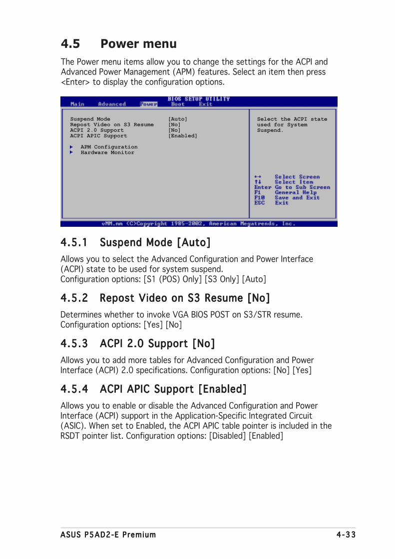
ASUS P5AD2-E PremiumASUS P5AD2-E PremiumASUS P5AD2-E PremiumASUS P5AD2-E PremiumASUS P5AD2-E Premium 4 -334 -334 -334 -334 -33
4.5 Power menu
The Power menu items allow you to change the settings for the ACPI andAdvanced Power Management (APM) features. Select an item then press<Enter> to display the configuration options.
4.5.14.5.14.5.14.5.14.5.1 Suspend Mode [Auto]Suspend Mode [Auto]Suspend Mode [Auto]Suspend Mode [Auto]Suspend Mode [Auto]
Allows you to select the Advanced Configuration and Power Interface(ACPI) state to be used for system suspend.Configuration options: [S1 (POS) Only] [S3 Only] [Auto]
4.5.24.5.24.5.24.5.24.5.2 Repost Video on S3 Resume [No]Repost Video on S3 Resume [No]Repost Video on S3 Resume [No]Repost Video on S3 Resume [No]Repost Video on S3 Resume [No]
Determines whether to invoke VGA BIOS POST on S3/STR resume.Configuration options: [Yes] [No]
4.5.34.5.34.5.34.5.34.5.3 ACPI 2.0 Support [No]ACPI 2.0 Support [No]ACPI 2.0 Support [No]ACPI 2.0 Support [No]ACPI 2.0 Support [No]
Allows you to add more tables for Advanced Configuration and PowerInterface (ACPI) 2.0 specifications. Configuration options: [No] [Yes]
4.5.44.5.44.5.44.5.44.5.4 ACPI APIC Support [Enabled]ACPI APIC Support [Enabled]ACPI APIC Support [Enabled]ACPI APIC Support [Enabled]ACPI APIC Support [Enabled]
Allows you to enable or disable the Advanced Configuration and PowerInterface (ACPI) support in the Application-Specific Integrated Circuit(ASIC). When set to Enabled, the ACPI APIC table pointer is included in theRSDT pointer list. Configuration options: [Disabled] [Enabled]
Suspend Mode [Auto]Repost Video on S3 Resume [No]ACPI 2.0 Support [No]ACPI APIC Support [Enabled]
APM ConfigurationHardware Monitor
Select the ACPI stateused for SystemSuspend.
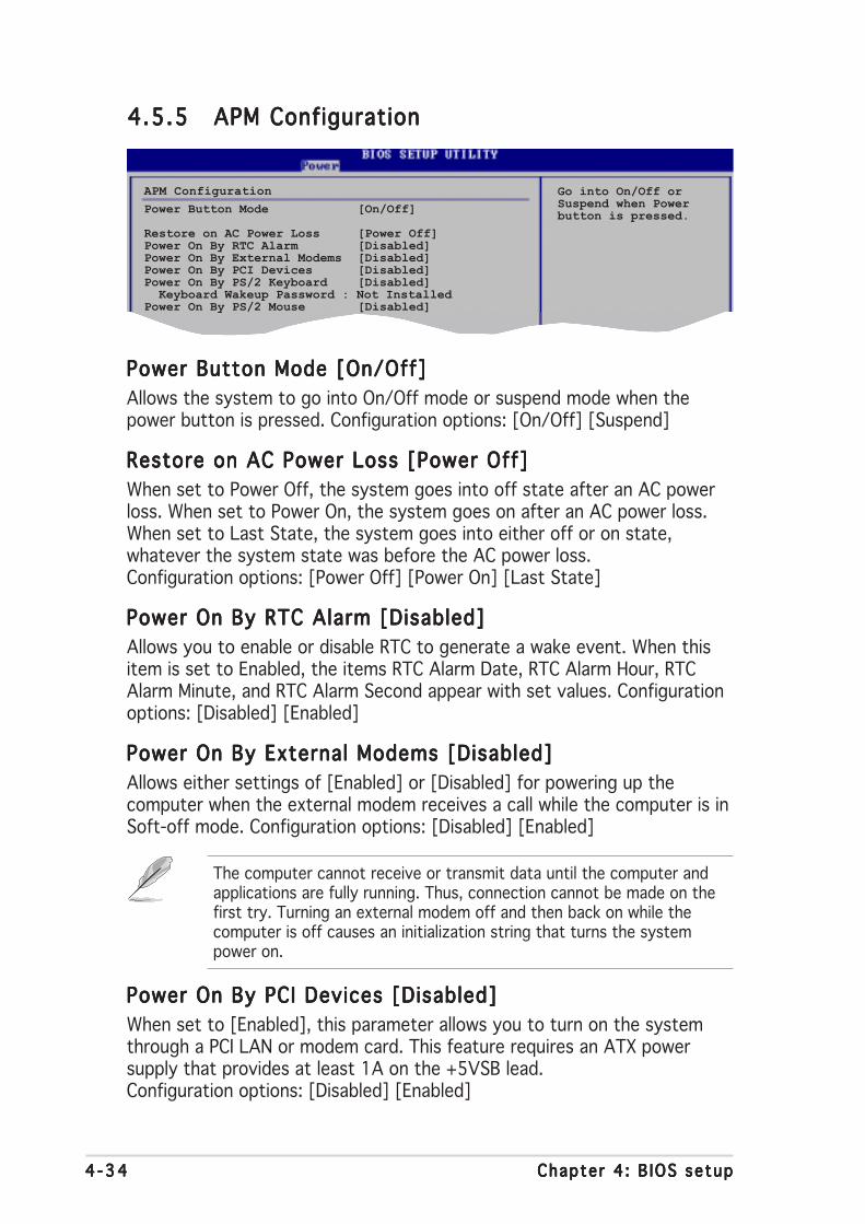
4 -344 -344 -344 -344 -34 Chapter 4 : B IOS setupChapter 4 : B IOS setupChapter 4 : B IOS setupChapter 4 : B IOS setupChapter 4 : B IOS setup
4.5.54.5.54.5.54.5.54.5.5 APM ConfigurationAPM ConfigurationAPM ConfigurationAPM ConfigurationAPM Configuration
Power Button Mode [On/Off]Power Button Mode [On/Off]Power Button Mode [On/Off]Power Button Mode [On/Off]Power Button Mode [On/Off]
Allows the system to go into On/Off mode or suspend mode when thepower button is pressed. Configuration options: [On/Off] [Suspend]
Restore on AC Power Loss [Power Off]Restore on AC Power Loss [Power Off]Restore on AC Power Loss [Power Off]Restore on AC Power Loss [Power Off]Restore on AC Power Loss [Power Off]
When set to Power Off, the system goes into off state after an AC powerloss. When set to Power On, the system goes on after an AC power loss.When set to Last State, the system goes into either off or on state,whatever the system state was before the AC power loss.Configuration options: [Power Off] [Power On] [Last State]
Power On By RTC Alarm [Disabled]Power On By RTC Alarm [Disabled]Power On By RTC Alarm [Disabled]Power On By RTC Alarm [Disabled]Power On By RTC Alarm [Disabled]
Allows you to enable or disable RTC to generate a wake event. When thisitem is set to Enabled, the items RTC Alarm Date, RTC Alarm Hour, RTCAlarm Minute, and RTC Alarm Second appear with set values. Configurationoptions: [Disabled] [Enabled]
Power On By External Modems [Disabled]Power On By External Modems [Disabled]Power On By External Modems [Disabled]Power On By External Modems [Disabled]Power On By External Modems [Disabled]
Allows either settings of [Enabled] or [Disabled] for powering up thecomputer when the external modem receives a call while the computer is inSoft-off mode. Configuration options: [Disabled] [Enabled]
The computer cannot receive or transmit data until the computer andapplications are fully running. Thus, connection cannot be made on thefirst try. Turning an external modem off and then back on while thecomputer is off causes an initialization string that turns the systempower on.
Power On By PCI Devices [Disabled]Power On By PCI Devices [Disabled]Power On By PCI Devices [Disabled]Power On By PCI Devices [Disabled]Power On By PCI Devices [Disabled]
When set to [Enabled], this parameter allows you to turn on the systemthrough a PCI LAN or modem card. This feature requires an ATX powersupply that provides at least 1A on the +5VSB lead.Configuration options: [Disabled] [Enabled]
APM Configuration
Power Button Mode [On/Off]
Restore on AC Power Loss [Power Off]Power On By RTC Alarm [Disabled]Power On By External Modems [Disabled]Power On By PCI Devices [Disabled]Power On By PS/2 Keyboard [Disabled] Keyboard Wakeup Password : Not InstalledPower On By PS/2 Mouse [Disabled]
Go into On/Off orSuspend when Powerbutton is pressed.

ASUS P5AD2-E PremiumASUS P5AD2-E PremiumASUS P5AD2-E PremiumASUS P5AD2-E PremiumASUS P5AD2-E Premium 4 -354 -354 -354 -354 -35
Power On By PS/2 Keyboard [Disabled]Power On By PS/2 Keyboard [Disabled]Power On By PS/2 Keyboard [Disabled]Power On By PS/2 Keyboard [Disabled]Power On By PS/2 Keyboard [Disabled]
Allows you to use specific keys on the keyboard to turn on the system.This feature requires an ATX power supply that provides at least 1A on the+5VSB lead. Configuration options: [Disabled] [Enabled]
Wakeup PasswordWakeup PasswordWakeup PasswordWakeup PasswordWakeup Password
This item appears only when the Power On By PS/2 Keyboard Power On By PS/2 Keyboard Power On By PS/2 Keyboard Power On By PS/2 Keyboard Power On By PS/2 Keyboard is setto [Enabled]. Select this item, then press <Enter> to set or change thekeyboard wakeup password.
Keyboard Wakeup Password
Shows [Not Insta l led][Not Insta l led][Not Insta l led][Not Insta l led][Not Insta l led] if the Wakeup Password Wakeup Password Wakeup Password Wakeup Password Wakeup Password is disabled. Afteryou have set a keyboard password, this item shows [ Insta l led][ Insta l led][ Insta l led][ Insta l led][ Insta l led].
Power On By PS/2 Mouse [Disabled]Power On By PS/2 Mouse [Disabled]Power On By PS/2 Mouse [Disabled]Power On By PS/2 Mouse [Disabled]Power On By PS/2 Mouse [Disabled]
When set to [Enabled], this parameter allows you to use the PS/2 mouseto turn on the system. This feature requires an ATX power supply thatprovides at least 1A on the +5VSB lead. Configuration options: [Disabled][Enabled]

4 -364 -364 -364 -364 -36 Chapter 4 : B IOS setupChapter 4 : B IOS setupChapter 4 : B IOS setupChapter 4 : B IOS setupChapter 4 : B IOS setup
4.5.64.5.64.5.64.5.64.5.6 Hardware MonitorHardware MonitorHardware MonitorHardware MonitorHardware Monitor
Hardware Monitor
CPU Temperature [32.5ºC/90.5ºF]MB Temperature [36.0ºC/96.5ºF]
CPU Fan Speed [3813 RPM]CPU Q-Fan Control [Disabled]Chassis Fan1 Speed [N/A]Power Fan Speed [N/A]
VCORE Voltage [ 1.320V]3.3V Voltage [ 3.345V]5V Voltage [ 5.094V]12V Voltage [11.880V]
CPU Temperature [xx.xºC/xx.xºF]CPU Temperature [xx.xºC/xx.xºF]CPU Temperature [xx.xºC/xx.xºF]CPU Temperature [xx.xºC/xx.xºF]CPU Temperature [xx.xºC/xx.xºF]MB Temperature [xx.xºC/xx.xºF]MB Temperature [xx.xºC/xx.xºF]MB Temperature [xx.xºC/xx.xºF]MB Temperature [xx.xºC/xx.xºF]MB Temperature [xx.xºC/xx.xºF]
The onboard hardware monitor automatically detects and displays themotherboard and CPU temperatures. Select [Disabled] if you do not wish todisplay the detected temperatures.
CPU Fan Speed [xxxx RPM] or [N/A]CPU Fan Speed [xxxx RPM] or [N/A]CPU Fan Speed [xxxx RPM] or [N/A]CPU Fan Speed [xxxx RPM] or [N/A]CPU Fan Speed [xxxx RPM] or [N/A]
The onboard hardware monitor automatically detects and displays the CPUfan speed in rotations per minute (RPM). If the fan is not connected to themotherboard, the field shows N/A.
CPU Q-Fan Control [Disabled]CPU Q-Fan Control [Disabled]CPU Q-Fan Control [Disabled]CPU Q-Fan Control [Disabled]CPU Q-Fan Control [Disabled]
Allows you to enable or disable the ASUS Q-Fan feature that smartlyadjusts the fan speeds for more efficient system operation. Configurationoptions: [Disabled] [Enabled]
The CPU Q-Fan ModeCPU Q-Fan ModeCPU Q-Fan ModeCPU Q-Fan ModeCPU Q-Fan Mode, CPU Fan Rat ioCPU Fan Rat ioCPU Fan Rat ioCPU Fan Rat ioCPU Fan Rat io, CPU TargetCPU TargetCPU TargetCPU TargetCPU TargetTemperatureTemperatureTemperatureTemperatureTemperature, and Chass is Q-Fan Contro l Chass is Q-Fan Contro l Chass is Q-Fan Contro l Chass is Q-Fan Contro l Chass is Q-Fan Contro l items appear when youenable the CPU Q-Fan Contro l CPU Q-Fan Contro l CPU Q-Fan Contro l CPU Q-Fan Contro l CPU Q-Fan Contro l feature.
CPU Q-Fan Mode [PWM]CPU Q-Fan Mode [PWM]CPU Q-Fan Mode [PWM]CPU Q-Fan Mode [PWM]CPU Q-Fan Mode [PWM]
Allows you to select the type of CPU fan cable connected to the CPU fanconnector. Set to [PWM] when using a 4-pin CPU fan cable. Set to [DC]when using a 3-pin CPU fan cable. Configuration options: [PWM] [DC]
Some CPU fans with a 4-pin cable do not comply with Intel®’s PWM fanspecification. When using this type of CPU fan, you can not reduce theCPU fan speed even if you set the CPU Q-Fan Mode to [PWM].

ASUS P5AD2-E PremiumASUS P5AD2-E PremiumASUS P5AD2-E PremiumASUS P5AD2-E PremiumASUS P5AD2-E Premium 4 -374 -374 -374 -374 -37
CPU Fan Ratio [Auto]CPU Fan Ratio [Auto]CPU Fan Ratio [Auto]CPU Fan Ratio [Auto]CPU Fan Ratio [Auto]
Allows you to select the appropriate CPU fan speed ratio for the system.The default [Auto] automatically selects the fan speed ratio whenoperating a low CPU temperature. Select a higher ratio if you installedadditional devices and the system requires more ventilation.Configuration options: [Auto] [90%] [80%] [70%] [60%]
CPU Target Temperature [xxxºC]CPU Target Temperature [xxxºC]CPU Target Temperature [xxxºC]CPU Target Temperature [xxxºC]CPU Target Temperature [xxxºC]
Allows you to set the CPU temperature threshold when the CPU fan speedis increased to lower the CPU temperature. The configuration options forthis item depend on the recommended Intel® Fan Speed Control (FSC)temperature settings. The Intel® FSC provides target temperature optionsat ±15 ºC with 3 ºC interval.
Chassis Fan1 Speed [xxxxRPM] or [N/A]Chassis Fan1 Speed [xxxxRPM] or [N/A]Chassis Fan1 Speed [xxxxRPM] or [N/A]Chassis Fan1 Speed [xxxxRPM] or [N/A]Chassis Fan1 Speed [xxxxRPM] or [N/A]
The onboard hardware monitor automatically detects and displays thechassis fan speed in rotations per minute (RPM). If the fan is not connectedto the chassis, the specific field shows N/A.
Chassis Q-Fan Control [Disabled]Chassis Q-Fan Control [Disabled]Chassis Q-Fan Control [Disabled]Chassis Q-Fan Control [Disabled]Chassis Q-Fan Control [Disabled]
Allows ysou to enable or disable the ASUS Q-Fan feature that smartlyadjusts the chassis fan speeds for more efficient system operation. Whenenabled, the chassis fan ratio is the same with the selected CPU fan ratio.Configuration options: [Disabled] [Enabled]
Power Fan Speed [xxxxRPM] or [N/A]Power Fan Speed [xxxxRPM] or [N/A]Power Fan Speed [xxxxRPM] or [N/A]Power Fan Speed [xxxxRPM] or [N/A]Power Fan Speed [xxxxRPM] or [N/A]
The onboard hardware monitor automatically detects and displays thepower fan speed in rotations per minute (RPM). If the fan is not connectedto the power fan connector, the specific field shows N/A.
VCORE Voltage, 3.3V Voltage, 5V Voltage, 12V VoltageVCORE Voltage, 3.3V Voltage, 5V Voltage, 12V VoltageVCORE Voltage, 3.3V Voltage, 5V Voltage, 12V VoltageVCORE Voltage, 3.3V Voltage, 5V Voltage, 12V VoltageVCORE Voltage, 3.3V Voltage, 5V Voltage, 12V Voltage
The onboard hardware monitor automatically detects the voltage outputthrough the onboard voltage regulators.
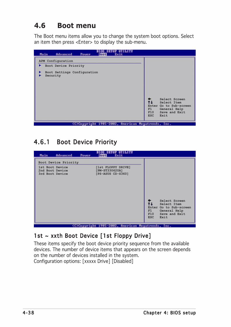
4 -384 -384 -384 -384 -38 Chapter 4 : B IOS setupChapter 4 : B IOS setupChapter 4 : B IOS setupChapter 4 : B IOS setupChapter 4 : B IOS setup
4.6 Boot menu
The Boot menu items allow you to change the system boot options. Selectan item then press <Enter> to display the sub-menu.
Select Screen Select ItemEnter Go to Sub-screenF1 General HelpF10 Save and ExitESC Exit
APM Configuration
Boot Device Priority
Boot Settings ConfigurationSecurity
4.6.14.6.14.6.14.6.14.6.1 Boot Device PriorityBoot Device PriorityBoot Device PriorityBoot Device PriorityBoot Device Priority
1st ~ xxth Boot Device [1st Floppy Drive]1st ~ xxth Boot Device [1st Floppy Drive]1st ~ xxth Boot Device [1st Floppy Drive]1st ~ xxth Boot Device [1st Floppy Drive]1st ~ xxth Boot Device [1st Floppy Drive]
These items specify the boot device priority sequence from the availabledevices. The number of device items that appears on the screen dependson the number of devices installed in the system.Configuration options: [xxxxx Drive] [Disabled]
Select Screen Select ItemEnter Go to Sub-screenF1 General HelpF10 Save and ExitESC Exit
Boot Device Priority
1st Boot Device [1st FLOPPY DRIVE]2nd Boot Device [PM-ST330620A]3rd Boot Device [PS-ASUS CD-S360]
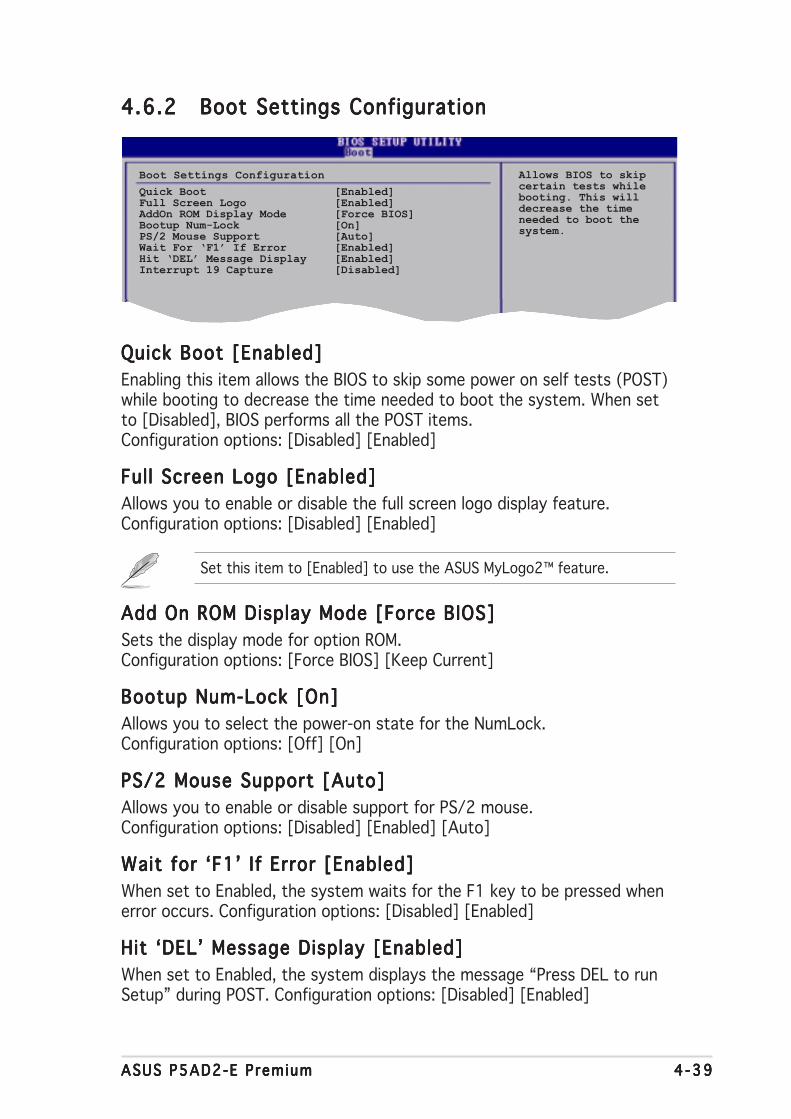
ASUS P5AD2-E PremiumASUS P5AD2-E PremiumASUS P5AD2-E PremiumASUS P5AD2-E PremiumASUS P5AD2-E Premium 4 -394 -394 -394 -394 -39
4.6.24.6.24.6.24.6.24.6.2 Boot Settings ConfigurationBoot Settings ConfigurationBoot Settings ConfigurationBoot Settings ConfigurationBoot Settings Configuration
Quick Boot [Enabled]Quick Boot [Enabled]Quick Boot [Enabled]Quick Boot [Enabled]Quick Boot [Enabled]
Enabling this item allows the BIOS to skip some power on self tests (POST)while booting to decrease the time needed to boot the system. When setto [Disabled], BIOS performs all the POST items.Configuration options: [Disabled] [Enabled]
Full Screen Logo [Enabled]Full Screen Logo [Enabled]Full Screen Logo [Enabled]Full Screen Logo [Enabled]Full Screen Logo [Enabled]
Allows you to enable or disable the full screen logo display feature.Configuration options: [Disabled] [Enabled]
Set this item to [Enabled] to use the ASUS MyLogo2™ feature.
Add On ROM Display Mode [Force BIOS]Add On ROM Display Mode [Force BIOS]Add On ROM Display Mode [Force BIOS]Add On ROM Display Mode [Force BIOS]Add On ROM Display Mode [Force BIOS]
Sets the display mode for option ROM.Configuration options: [Force BIOS] [Keep Current]
Bootup Num-Lock [On]Bootup Num-Lock [On]Bootup Num-Lock [On]Bootup Num-Lock [On]Bootup Num-Lock [On]
Allows you to select the power-on state for the NumLock.Configuration options: [Off] [On]
PS/2 Mouse Support [Auto]PS/2 Mouse Support [Auto]PS/2 Mouse Support [Auto]PS/2 Mouse Support [Auto]PS/2 Mouse Support [Auto]
Allows you to enable or disable support for PS/2 mouse.Configuration options: [Disabled] [Enabled] [Auto]
Wait for ‘F1’ If Error [Enabled]Wait for ‘F1’ If Error [Enabled]Wait for ‘F1’ If Error [Enabled]Wait for ‘F1’ If Error [Enabled]Wait for ‘F1’ If Error [Enabled]
When set to Enabled, the system waits for the F1 key to be pressed whenerror occurs. Configuration options: [Disabled] [Enabled]
Hit ‘DEL’ Message Display [Enabled]Hit ‘DEL’ Message Display [Enabled]Hit ‘DEL’ Message Display [Enabled]Hit ‘DEL’ Message Display [Enabled]Hit ‘DEL’ Message Display [Enabled]
When set to Enabled, the system displays the message “Press DEL to runSetup” during POST. Configuration options: [Disabled] [Enabled]
Boot Settings Configuration
Quick Boot [Enabled]Full Screen Logo [Enabled]AddOn ROM Display Mode [Force BIOS]Bootup Num-Lock [On]PS/2 Mouse Support [Auto]Wait For ‘F1’ If Error [Enabled]Hit ‘DEL’ Message Display [Enabled]Interrupt 19 Capture [Disabled]
Allows BIOS to skipcertain tests whilebooting. This willdecrease the timeneeded to boot thesystem.
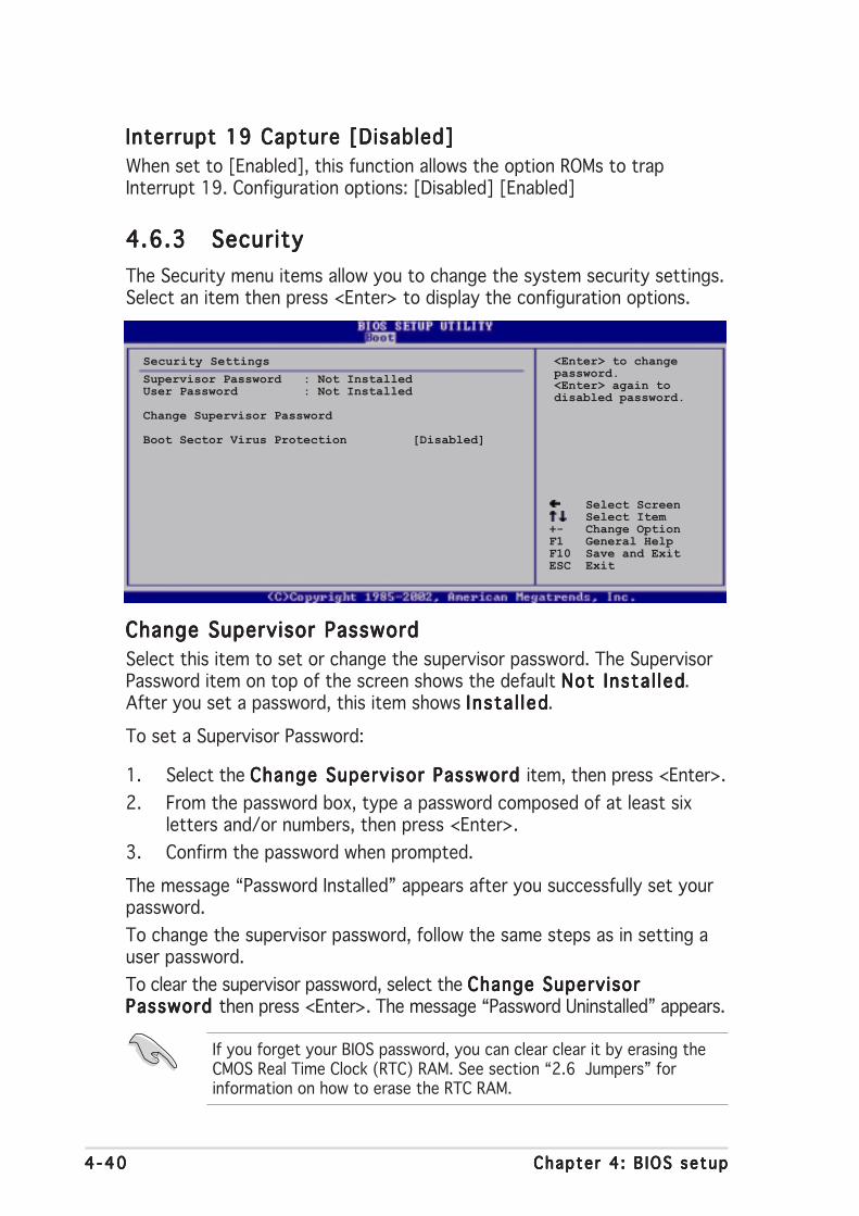
4 -404 -404 -404 -404 -40 Chapter 4 : B IOS setupChapter 4 : B IOS setupChapter 4 : B IOS setupChapter 4 : B IOS setupChapter 4 : B IOS setup
Interrupt 19 Capture [Disabled]Interrupt 19 Capture [Disabled]Interrupt 19 Capture [Disabled]Interrupt 19 Capture [Disabled]Interrupt 19 Capture [Disabled]
When set to [Enabled], this function allows the option ROMs to trapInterrupt 19. Configuration options: [Disabled] [Enabled]
4.6.34.6.34.6.34.6.34.6.3 SecuritySecuritySecuritySecuritySecurity
The Security menu items allow you to change the system security settings.Select an item then press <Enter> to display the configuration options.
Select Screen Select Item+- Change OptionF1 General HelpF10 Save and ExitESC Exit
Security Settings
Supervisor Password : Not InstalledUser Password : Not Installed
Change Supervisor Password
Boot Sector Virus Protection [Disabled]
<Enter> to changepassword.<Enter> again todisabled password.
Change Supervisor PasswordChange Supervisor PasswordChange Supervisor PasswordChange Supervisor PasswordChange Supervisor Password
Select this item to set or change the supervisor password. The SupervisorPassword item on top of the screen shows the default Not Insta l ledNot Insta l ledNot Insta l ledNot Insta l ledNot Insta l led.After you set a password, this item shows Insta l ledInsta l ledInsta l ledInsta l ledInsta l led.
To set a Supervisor Password:
1. Select the Change Supervisor Password Change Supervisor Password Change Supervisor Password Change Supervisor Password Change Supervisor Password item, then press <Enter>.
2. From the password box, type a password composed of at least sixletters and/or numbers, then press <Enter>.
3. Confirm the password when prompted.
The message “Password Installed” appears after you successfully set yourpassword.
To change the supervisor password, follow the same steps as in setting auser password.
To clear the supervisor password, select the Change SupervisorChange SupervisorChange SupervisorChange SupervisorChange SupervisorPassword Password Password Password Password then press <Enter>. The message “Password Uninstalled” appears.
If you forget your BIOS password, you can clear clear it by erasing theCMOS Real Time Clock (RTC) RAM. See section “2.6 Jumpers” forinformation on how to erase the RTC RAM.

ASUS P5AD2-E PremiumASUS P5AD2-E PremiumASUS P5AD2-E PremiumASUS P5AD2-E PremiumASUS P5AD2-E Premium 4 -414 -414 -414 -414 -41
After you have set a supervisor password, the other items appear to allowyou to change other security settings.
User Access Level [Full Access]User Access Level [Full Access]User Access Level [Full Access]User Access Level [Full Access]User Access Level [Full Access]
This item allows you to select the access restriction to the Setup items.Configuration options: [No Access] [View Only] [Limited] [Full Access]
No AccessNo AccessNo AccessNo AccessNo Access prevents user access to the Setup utility.
V iew Only V iew Only V iew Only V iew Only V iew Only allows access but does not allow change to any field.
L imited L imited L imited L imited L imited allows changes only to selected fields, such as Date andTime.
Fu l l AccessFu l l AccessFu l l AccessFu l l AccessFu l l Access allows viewing and changing all the fields in the Setuputility.
Change User PasswordChange User PasswordChange User PasswordChange User PasswordChange User Password
Select this item to set or change the user password. The User PasswordUser PasswordUser PasswordUser PasswordUser Passworditem on top of the screen shows the default Not Insta l ledNot Insta l ledNot Insta l ledNot Insta l ledNot Insta l led. After you seta password, this item shows Insta l ledInsta l ledInsta l ledInsta l ledInsta l led.
To set a User Password:
1. Select the Change User Password item and press <Enter>.
2. On the password box that appears, type a password composed of atleast six letters and/or numbers, then press <Enter>.
3. Confirm the password when prompted.
The message “Password Installed” appears after you set your passwordsuccessfully.
To change the user password, follow the same steps as in setting a userpassword.
Select Screen Select Item+- Change OptionF1 General HelpF10 Save and ExitESC Exit
Security Settings
Supervisor Password : Not InstalledUser Password : Not Installed
Change Supervisor PasswordUser Access Level [Full Access]Change User PasswordClear User PasswordPassword Check [Setup]
Boot Sector Virus Protection [Disabled]

4 -424 -424 -424 -424 -42 Chapter 4 : B IOS setupChapter 4 : B IOS setupChapter 4 : B IOS setupChapter 4 : B IOS setupChapter 4 : B IOS setup
Clear User PasswordClear User PasswordClear User PasswordClear User PasswordClear User Password
Select this item to clear the user password.
Password Check [Setup]Password Check [Setup]Password Check [Setup]Password Check [Setup]Password Check [Setup]
When set to [Setup], BIOS checks for user password when accessing theSetup utility. When set to [Always], BIOS checks for user password bothwhen accessing Setup and booting the system.Configuration options: [Setup] [Always]
Boot Sector Virus Protection [Disabled]Boot Sector Virus Protection [Disabled]Boot Sector Virus Protection [Disabled]Boot Sector Virus Protection [Disabled]Boot Sector Virus Protection [Disabled]
Allows you to enable or disable the boot sector virus protection.Configuration options: [Disabled] [Enabled]

ASUS P5AD2-E PremiumASUS P5AD2-E PremiumASUS P5AD2-E PremiumASUS P5AD2-E PremiumASUS P5AD2-E Premium 4 -434 -434 -434 -434 -43
Exit & Discard ChangesExit & Discard ChangesExit & Discard ChangesExit & Discard ChangesExit & Discard Changes
Select this option only if you do not want to save the changes that youmade to the Setup program. If you made changes to fields other thanSystem Date, System Time, and Password, the BIOS asks for a confirmationbefore exiting.
Discard ChangesDiscard ChangesDiscard ChangesDiscard ChangesDiscard Changes
Allows you to discard the selections you made and restore the previouslysaved values. After selecting this option, a confirmation appears. SelectY e sY e sY e sY e sY e s to discard any changes and load the previously saved values.
Exit & Save ChangesExit & Save ChangesExit & Save ChangesExit & Save ChangesExit & Save Changes
Once you are finished making your selections, choose this option from theExit menu to ensure the values you selected are saved to the CMOS RAM.An onboard backup battery sustains the CMOS RAM so it stays on evenwhen the computer is turned off. When you select this option, aconfirmation window appears. Select Y e sY e sY e sY e sY e s to save the changes and exit.
If you attempt to exit the Setup program without saving your changes,the program prompts you with a message asking if you want to saveyour changes before exiting. Press <Enter> to save the changes whileexiting.
Exit system setupafter saving thechanges.
F10 key can be usedfor this operation.
Select Screen Select ItemEnter Go to Sub-screenF1 General HelpF10 Save and ExitESC Exit
Exit Options
Exit & Save ChangesExit & Discard ChangesDiscard Changes
Load Setup Defaults
Pressing <Esc> does not immediately exit this menu. Select one of theoptions from this menu or <F10> from the legend bar to exit.
4.7 Exit menu
The Exit menu items allow you to load the optimal or failsafe default valuesfor the BIOS items, and save or discard your changes to the BIOS items.

4 -444 -444 -444 -444 -44 Chapter 4 : B IOS setupChapter 4 : B IOS setupChapter 4 : B IOS setupChapter 4 : B IOS setupChapter 4 : B IOS setup
Load Setup DefaultsLoad Setup DefaultsLoad Setup DefaultsLoad Setup DefaultsLoad Setup Defaults
Allows you to load the default values for each of the parameters on theSetup menus. When you select this option or if you press <F5>, aconfirmation window appears. Select Y e sY e sY e sY e sY e s to load default values. SelectEx it & Save ChangesEx it & Save ChangesEx it & Save ChangesEx it & Save ChangesEx it & Save Changes or make other changes before saving the valuesto the non-volatile RAM.

5Softwaresupport
This chapter describes the contentsof the support CD that comes withthe motherboard package.

ASUS P5AD2-E PremiumASUS P5AD2-E PremiumASUS P5AD2-E PremiumASUS P5AD2-E PremiumASUS P5AD2-E Premium
Chapter summary 55.1 Installing an operating system ............................................. 5-1
5.2 Support CD information ........................................................ 5-1
5.3 IEEE 1394b driver information ............................................. 5-8
5.4 Software information ......................................................... 5-11
5.5 RAID configurations ............................................................ 5-19
5.6 Creating a RAID driver disk ................................................. 5-42
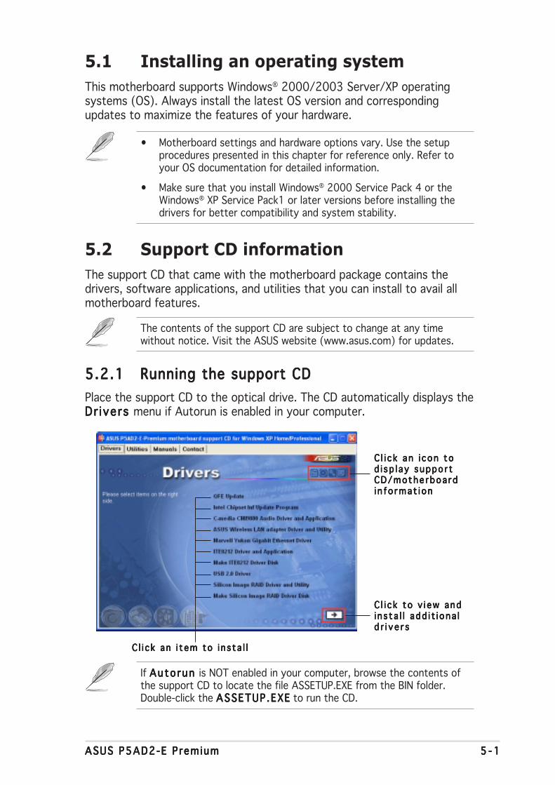
ASUS P5AD2-E PremiumASUS P5AD2-E PremiumASUS P5AD2-E PremiumASUS P5AD2-E PremiumASUS P5AD2-E Premium 5 - 15 - 15 - 15 - 15 - 1
5.1 Installing an operating system
This motherboard supports Windows® 2000/2003 Server/XP operatingsystems (OS). Always install the latest OS version and correspondingupdates to maximize the features of your hardware.
5.2 Support CD information
The support CD that came with the motherboard package contains thedrivers, software applications, and utilities that you can install to avail allmotherboard features.
5.2.15.2.15.2.15.2.15.2.1 Running the support CDRunning the support CDRunning the support CDRunning the support CDRunning the support CD
Place the support CD to the optical drive. The CD automatically displays theDr ivers Dr ivers Dr ivers Dr ivers Dr ivers menu if Autorun is enabled in your computer.
C l i c k an i con toC l i c k an i con toC l i c k an i con toC l i c k an i con toC l i c k an i con tod i sp l ay suppo r td i sp l ay suppo r td i sp l ay suppo r td i sp l ay suppo r td i sp l ay suppo r tCD/mothe rboa rdCD/mothe rboa rdCD/mothe rboa rdCD/mothe rboa rdCD/mothe rboa rdi n f o rmat i oni n f o rmat i oni n f o rmat i oni n f o rmat i oni n f o rmat i on
C l i c k an i t em to i n s ta l lC l i c k an i t em to i n s ta l lC l i c k an i t em to i n s ta l lC l i c k an i t em to i n s ta l lC l i c k an i t em to i n s ta l l
• Motherboard settings and hardware options vary. Use the setupprocedures presented in this chapter for reference only. Refer toyour OS documentation for detailed information.
• Make sure that you install Windows® 2000 Service Pack 4 or theWindows® XP Service Pack1 or later versions before installing thedrivers for better compatibility and system stability.
If Auto run Auto run Auto run Auto run Auto run is NOT enabled in your computer, browse the contents ofthe support CD to locate the file ASSETUP.EXE from the BIN folder.Double-click the ASSETUP .EXEASSETUP .EXEASSETUP .EXEASSETUP .EXEASSETUP .EXE to run the CD.
The contents of the support CD are subject to change at any timewithout notice. Visit the ASUS website (www.asus.com) for updates.
C l i c k to v i ew andC l i c k to v i ew andC l i c k to v i ew andC l i c k to v i ew andC l i c k to v i ew andi n s ta l l add i t i ona li n s ta l l add i t i ona li n s ta l l add i t i ona li n s ta l l add i t i ona li n s ta l l add i t i ona ld r i v e r sd r i v e r sd r i v e r sd r i v e r sd r i v e r s
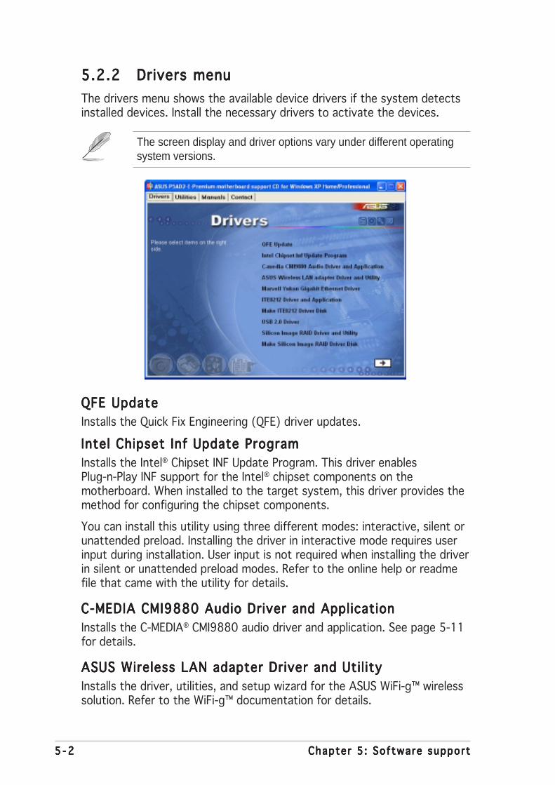
5 - 25 - 25 - 25 - 25 - 2 Chapter 5 : Software supportChapter 5 : Software supportChapter 5 : Software supportChapter 5 : Software supportChapter 5 : Software support
5.2.25.2.25.2.25.2.25.2.2 Drivers menuDrivers menuDrivers menuDrivers menuDrivers menu
The drivers menu shows the available device drivers if the system detectsinstalled devices. Install the necessary drivers to activate the devices.
QFE UpdateQFE UpdateQFE UpdateQFE UpdateQFE Update
Installs the Quick Fix Engineering (QFE) driver updates.
Intel Chipset Inf Update ProgramIntel Chipset Inf Update ProgramIntel Chipset Inf Update ProgramIntel Chipset Inf Update ProgramIntel Chipset Inf Update Program
Installs the Intel® Chipset INF Update Program. This driver enablesPlug-n-Play INF support for the Intel® chipset components on themotherboard. When installed to the target system, this driver provides themethod for configuring the chipset components.
You can install this utility using three different modes: interactive, silent orunattended preload. Installing the driver in interactive mode requires userinput during installation. User input is not required when installing the driverin silent or unattended preload modes. Refer to the online help or readmefile that came with the utility for details.
C-MEDIA CMI9880 Audio Driver and ApplicationC-MEDIA CMI9880 Audio Driver and ApplicationC-MEDIA CMI9880 Audio Driver and ApplicationC-MEDIA CMI9880 Audio Driver and ApplicationC-MEDIA CMI9880 Audio Driver and Application
Installs the C-MEDIA® CMI9880 audio driver and application. See page 5-11for details.
ASUS Wireless LAN adapter Driver and Util ityASUS Wireless LAN adapter Driver and Util ityASUS Wireless LAN adapter Driver and Util ityASUS Wireless LAN adapter Driver and Util ityASUS Wireless LAN adapter Driver and Util ity
Installs the driver, utilities, and setup wizard for the ASUS WiFi-g™ wirelesssolution. Refer to the WiFi-g™ documentation for details.
The screen display and driver options vary under different operatingsystem versions.
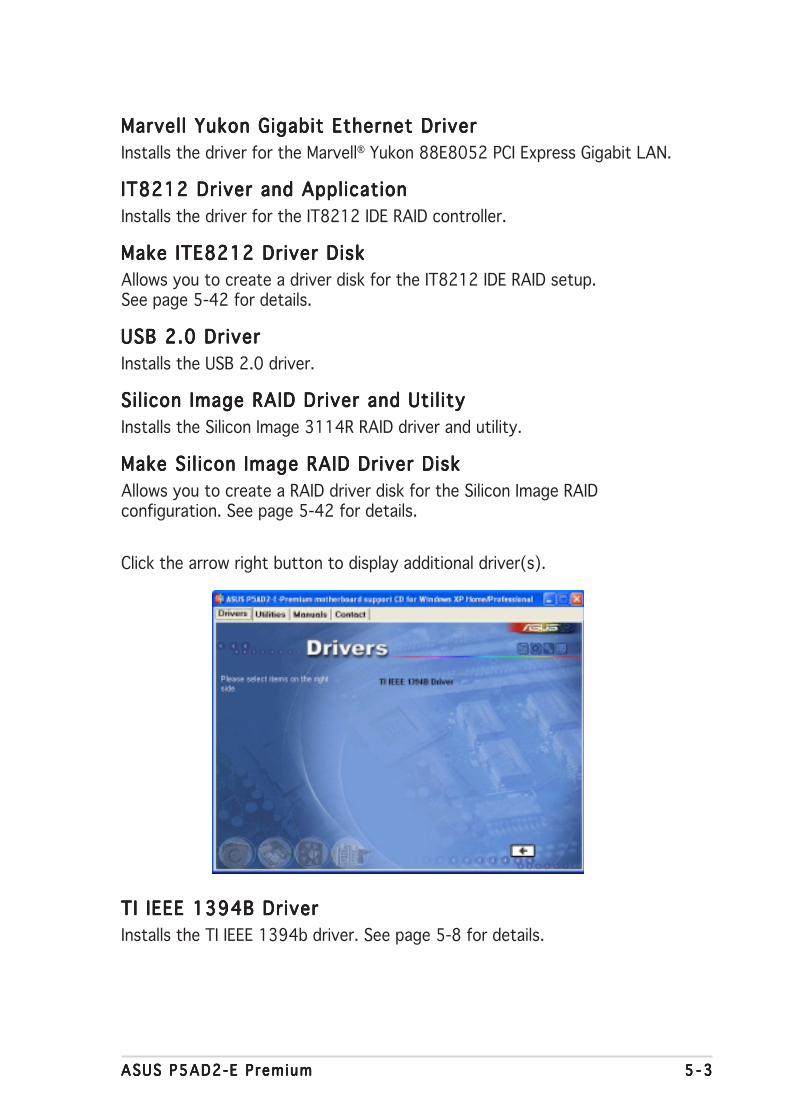
ASUS P5AD2-E PremiumASUS P5AD2-E PremiumASUS P5AD2-E PremiumASUS P5AD2-E PremiumASUS P5AD2-E Premium 5 - 35 - 35 - 35 - 35 - 3
Marvell Yukon Gigabit Ethernet DriverMarvell Yukon Gigabit Ethernet DriverMarvell Yukon Gigabit Ethernet DriverMarvell Yukon Gigabit Ethernet DriverMarvell Yukon Gigabit Ethernet Driver
Installs the driver for the Marvell® Yukon 88E8052 PCI Express Gigabit LAN.
IT8212 Driver and ApplicationIT8212 Driver and ApplicationIT8212 Driver and ApplicationIT8212 Driver and ApplicationIT8212 Driver and Application
Installs the driver for the IT8212 IDE RAID controller.
Make ITE8212 Driver DiskMake ITE8212 Driver DiskMake ITE8212 Driver DiskMake ITE8212 Driver DiskMake ITE8212 Driver Disk
Allows you to create a driver disk for the IT8212 IDE RAID setup.See page 5-42 for details.
USB 2.0 DriverUSB 2.0 DriverUSB 2.0 DriverUSB 2.0 DriverUSB 2.0 Driver
Installs the USB 2.0 driver.
Sil icon Image RAID Driver and Util itySil icon Image RAID Driver and Util itySil icon Image RAID Driver and Util itySil icon Image RAID Driver and Util itySil icon Image RAID Driver and Util ity
Installs the Silicon Image 3114R RAID driver and utility.
Make Sil icon Image RAID Driver DiskMake Sil icon Image RAID Driver DiskMake Sil icon Image RAID Driver DiskMake Sil icon Image RAID Driver DiskMake Sil icon Image RAID Driver Disk
Allows you to create a RAID driver disk for the Silicon Image RAIDconfiguration. See page 5-42 for details.
TI IEEE 1394B DriverTI IEEE 1394B DriverTI IEEE 1394B DriverTI IEEE 1394B DriverTI IEEE 1394B Driver
Installs the TI IEEE 1394b driver. See page 5-8 for details.
Click the arrow right button to display additional driver(s).

5 - 45 - 45 - 45 - 45 - 4 Chapter 5 : Software supportChapter 5 : Software supportChapter 5 : Software supportChapter 5 : Software supportChapter 5 : Software support
5.2.35.2.35.2.35.2.35.2.3 Utilities menuUtilities menuUtilities menuUtilities menuUtilities menu
The Ut i l i t iesUt i l i t iesUt i l i t iesUt i l i t iesUt i l i t ies menu displays the software applications and utilities that themotherboard supports. Click on an item to install.
Marvell Yukon VCT ApplicationMarvell Yukon VCT ApplicationMarvell Yukon VCT ApplicationMarvell Yukon VCT ApplicationMarvell Yukon VCT Application
The Virtual Cable Tester (VCT) is a cable diagnostic application that analyzesand reports LAN cable faults and shorts. See page 5-10 for details.
ASUS PC ProbeASUS PC ProbeASUS PC ProbeASUS PC ProbeASUS PC Probe
This smart utility monitors the fan speed, CPU temperature, and systemvoltages, and alerts you of any detected problems. This utility helps youkeep your computer in healthy operating condition.
ASUS UpdateASUS UpdateASUS UpdateASUS UpdateASUS Update
The ASUS Update utility that allows you to update the motherboard BIOS inWindows® environment. This utility requires an Internet connection eitherthrough a network or an Internet Service Provider (ISP). See page 4-8 fordetails.
AI BoosterAI BoosterAI BoosterAI BoosterAI Booster
The ASUS AI Booster application allows you to overclock the CPU speed inWindows® environment.
Microsoft DirectX 9.0bMicrosoft DirectX 9.0bMicrosoft DirectX 9.0bMicrosoft DirectX 9.0bMicrosoft DirectX 9.0b
The Microsoft DirectX® 9.0b is a multimedia technology that enhancescomputer graphics and sounds. DirectX® improves the multimedia featuresof your computer so you can enjoy watching TV and movies, capturingvideos, or playing games in your computer.

ASUS P5AD2-E PremiumASUS P5AD2-E PremiumASUS P5AD2-E PremiumASUS P5AD2-E PremiumASUS P5AD2-E Premium 5 - 55 - 55 - 55 - 55 - 5
5.2.45.2.45.2.45.2.45.2.4 Manuals menuManuals menuManuals menuManuals menuManuals menu
The Manua lsManua lsManua lsManua lsManua ls menu contains the user manuals for third party componentsand applications.
Most user manual files are in Portable Document Format (PDF). Installthe Adobe Acrobat Reader application from the Ut i l i t i es Ut i l i t i es Ut i l i t i es Ut i l i t i es Ut i l i t i es tab beforeopening a user manual file.
Anti-Virus Uti l ityAnti-Virus Uti l ityAnti-Virus Uti l ityAnti-Virus Uti l ityAnti-Virus Uti l ity
The anti-virus utility scans, identifies, and removes computer viruses. Viewthe online help for detailed information.
Winbond Voice EditorWinbond Voice EditorWinbond Voice EditorWinbond Voice EditorWinbond Voice Editor
This Voice Editor application allows you to record and customize wave filesfor the ASUS POST Reporter™ utility. Use this program to change thedefault vocal POST messages. See section “3.2 Vocal POST Messages” fordetails.
ADOBE Acrobat ReaderADOBE Acrobat ReaderADOBE Acrobat ReaderADOBE Acrobat ReaderADOBE Acrobat Reader
The Adobe Acrobat® Reader V5.0 is for opening, viewing, and printingdocuments in Portable Document Format (PDF).
ASUS Screen SaverASUS Screen SaverASUS Screen SaverASUS Screen SaverASUS Screen Saver
Installs the ASUS screen saver.
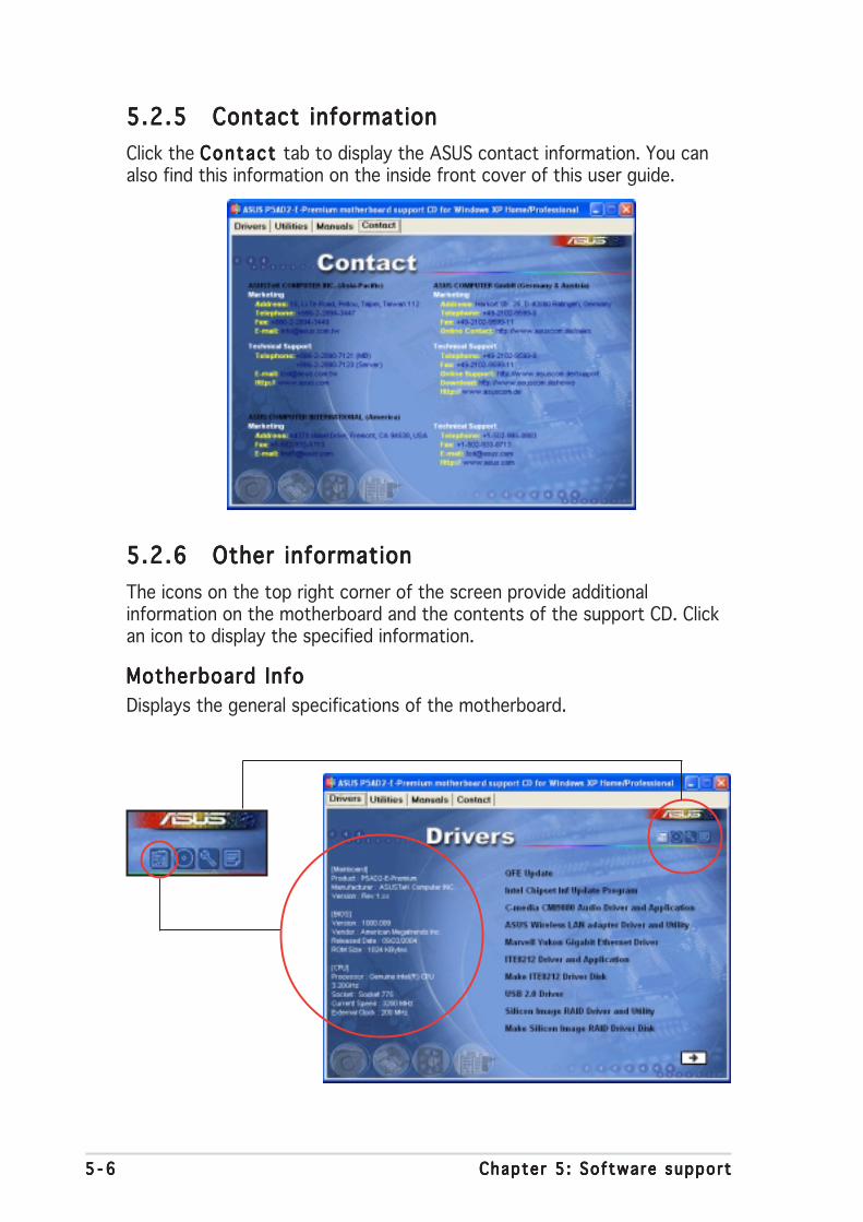
5 - 65 - 65 - 65 - 65 - 6 Chapter 5 : Software supportChapter 5 : Software supportChapter 5 : Software supportChapter 5 : Software supportChapter 5 : Software support
5.2.65.2.65.2.65.2.65.2.6 Other informationOther informationOther informationOther informationOther information
The icons on the top right corner of the screen provide additionalinformation on the motherboard and the contents of the support CD. Clickan icon to display the specified information.
Motherboard InfoMotherboard InfoMotherboard InfoMotherboard InfoMotherboard Info
Displays the general specifications of the motherboard.
5.2.55.2.55.2.55.2.55.2.5 Contact informationContact informationContact informationContact informationContact information
Click the Contact Contact Contact Contact Contact tab to display the ASUS contact information. You canalso find this information on the inside front cover of this user guide.
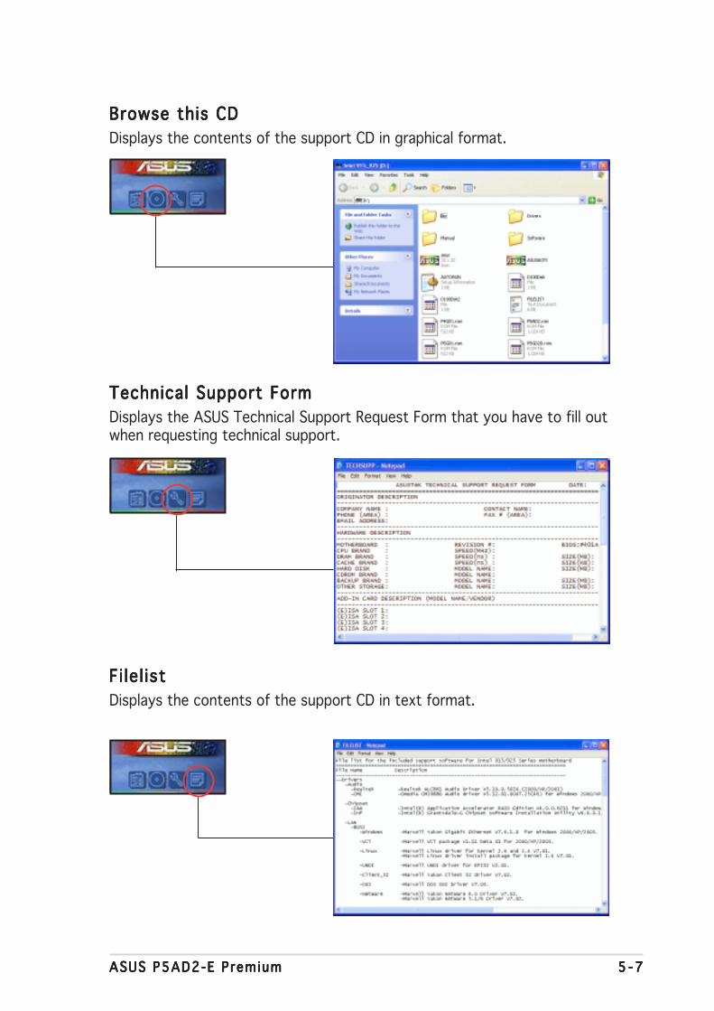
ASUS P5AD2-E PremiumASUS P5AD2-E PremiumASUS P5AD2-E PremiumASUS P5AD2-E PremiumASUS P5AD2-E Premium 5 - 75 - 75 - 75 - 75 - 7
Browse this CDBrowse this CDBrowse this CDBrowse this CDBrowse this CD
Displays the contents of the support CD in graphical format.
Technical Support FormTechnical Support FormTechnical Support FormTechnical Support FormTechnical Support Form
Displays the ASUS Technical Support Request Form that you have to fill outwhen requesting technical support.
Fi le l istFi lel istFi lel istFi lel istFi lel ist
Displays the contents of the support CD in text format.

5 - 85 - 85 - 85 - 85 - 8 Chapter 5 : Software supportChapter 5 : Software supportChapter 5 : Software supportChapter 5 : Software supportChapter 5 : Software support
5.3 IEEE 1394b driver information
You can connect your IEEE 1394b/a devices to the IEEE 1394b ports afterinstalling the IEEE 1394b/RJ-45 ports module and the TI IEEE 1394b driver.The IEEE 1394b ports fully support most IEEE 1394b/a consumerelectronic (CE) devices, except IEEE 1394a digital video (DV) camcorders.
If you want to connect a DV camcorder or other IEEE 1394a devices to theIEEE 1394b ports, use the Microsoft 1394 stack driver.
Your IEEE 1394a DV camcorder can achieve a maximum 100 Mbps datatransmission rate when connected to an IEEE 1394b port.
To switch to the Microsoft 1394 stack driver:
1. Right-click the M yM yM yM yM yComputer Computer Computer Computer Computer icon onyour desktop, thenselect Propert iesPropert iesPropert iesPropert iesPropert ies.
2. Click the HardwareHardwareHardwareHardwareHardwaretab when theSystemSystemSystemSystemSystemPropert iesPropert iesPropert iesPropert iesPropert ies windowappears.
3. Click the Dev iceDev iceDev iceDev iceDev iceManager Manager Manager Manager Manager button todisplay the installeddevices on yoursystem, then click the (+) sign before the item IEEE 1394 BusIEEE 1394 BusIEEE 1394 BusIEEE 1394 BusIEEE 1394 Bushost contro l lershost contro l lershost contro l lershost contro l lershost contro l lers.
This item shows Unibra in dr iver / S800 OHCI Compat ib le BoardUnibra in dr iver / S800 OHCI Compat ib le BoardUnibra in dr iver / S800 OHCI Compat ib le BoardUnibra in dr iver / S800 OHCI Compat ib le BoardUnibra in dr iver / S800 OHCI Compat ib le Boardif you previously installed the TI IEEE 1394b driver from the support CD.
4. Right-click the IEEE1394 controllerdriver, then selectUpdate Dr iver Update Dr iver Update Dr iver Update Dr iver Update Dr iver todisplay the HardwareUpdate WizardWindow.

ASUS P5AD2-E PremiumASUS P5AD2-E PremiumASUS P5AD2-E PremiumASUS P5AD2-E PremiumASUS P5AD2-E Premium 5 - 95 - 95 - 95 - 95 - 9
5. Select the optionInsta l l f rom a l istInsta l l f rom a l istInsta l l f rom a l istInsta l l f rom a l istInsta l l f rom a l istor spec i f icor spec i f icor spec i f icor spec i f icor spec i f iclocat ionlocat ionlocat ionlocat ionlocat ion(Advanced)(Advanced)(Advanced)(Advanced)(Advanced), thenclick NextNextNextNextNext.
6. Select the optionDon ’t search, IDon ’t search, IDon ’t search, IDon ’t search, IDon ’t search, Iw i l l choose thewi l l choose thewi l l choose thewi l l choose thewi l l choose thedr iver to insta l ldr iver to insta l ldr iver to insta l ldr iver to insta l ldr iver to insta l l,then click NextNextNextNextNext.
7. Select the Microsoft1394 stack driverfrom the list, thenclick NextNextNextNextNext.
The Microsoft 1394 stack driver follows the IEEE 1394 OHCI hostcontoller. For this motherboard, the Microsoft 1394 stack driver is theTexas Instrument OHCI IEEE 1394 Host Controller.
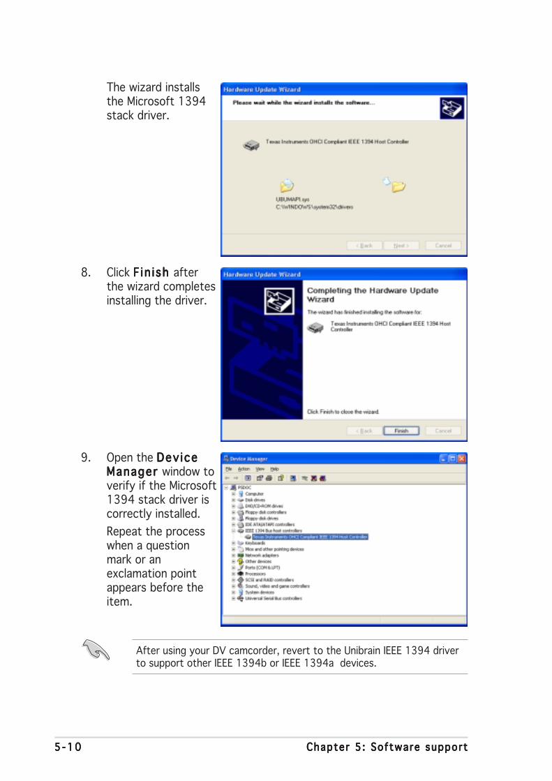
5 -105 -105 -105 -105 -10 Chapter 5 : Software supportChapter 5 : Software supportChapter 5 : Software supportChapter 5 : Software supportChapter 5 : Software support
The wizard installsthe Microsoft 1394stack driver.
8. Click F in i sh F in i sh F in i sh F in i sh F in i sh afterthe wizard completesinstalling the driver.
9. Open the Dev iceDev iceDev iceDev iceDev iceManager Manager Manager Manager Manager window toverify if the Microsoft1394 stack driver iscorrectly installed.
Repeat the processwhen a questionmark or anexclamation pointappears before theitem.
After using your DV camcorder, revert to the Unibrain IEEE 1394 driverto support other IEEE 1394b or IEEE 1394a devices.
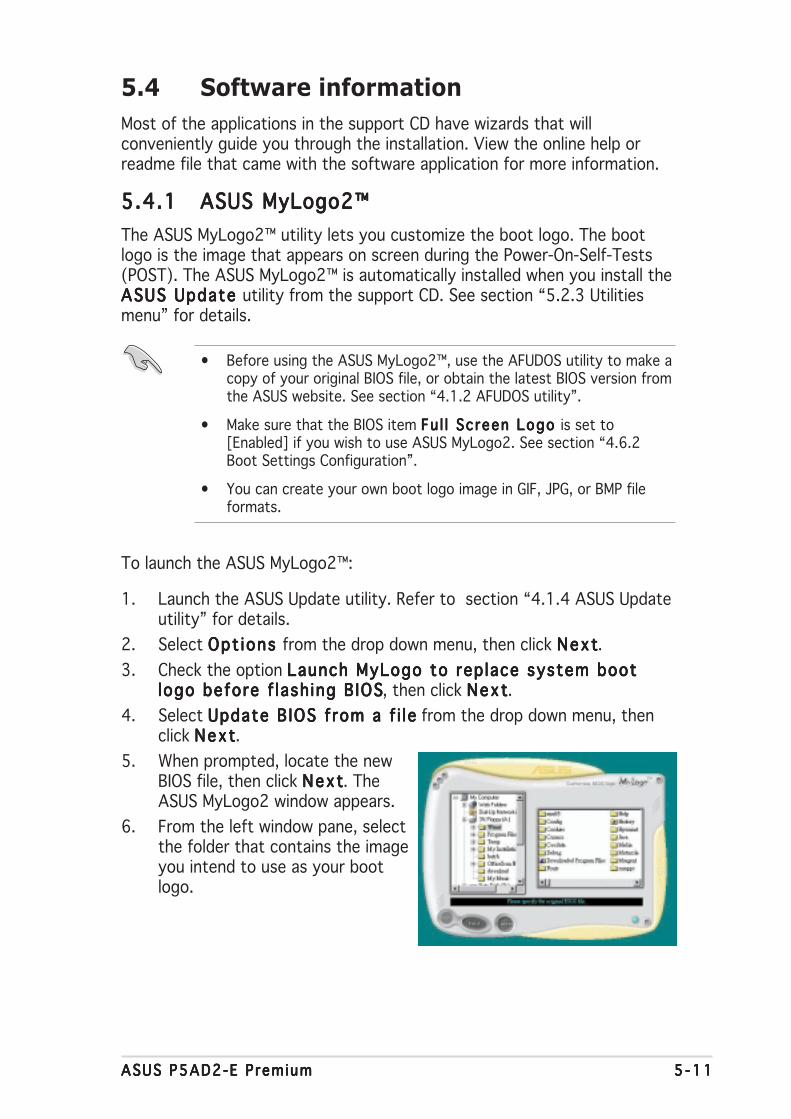
ASUS P5AD2-E PremiumASUS P5AD2-E PremiumASUS P5AD2-E PremiumASUS P5AD2-E PremiumASUS P5AD2-E Premium 5 -115 -115 -115 -115 -11
5.4 Software information
Most of the applications in the support CD have wizards that willconveniently guide you through the installation. View the online help orreadme file that came with the software application for more information.
5.4.15.4.15.4.15.4.15.4.1 ASUS MyLogo2™ASUS MyLogo2™ASUS MyLogo2™ASUS MyLogo2™ASUS MyLogo2™
The ASUS MyLogo2™ utility lets you customize the boot logo. The bootlogo is the image that appears on screen during the Power-On-Self-Tests(POST). The ASUS MyLogo2™ is automatically installed when you install theASUS Update ASUS Update ASUS Update ASUS Update ASUS Update utility from the support CD. See section “5.2.3 Utilitiesmenu” for details.
To launch the ASUS MyLogo2™:
1. Launch the ASUS Update utility. Refer to section “4.1.4 ASUS Updateutility” for details.
2. Select Opt ions Opt ions Opt ions Opt ions Opt ions from the drop down menu, then click NextNextNextNextNext.
3. Check the option Launch MyLogo to replace system bootLaunch MyLogo to replace system bootLaunch MyLogo to replace system bootLaunch MyLogo to replace system bootLaunch MyLogo to replace system bootlogo before f lash ing BIOSlogo before f lash ing BIOSlogo before f lash ing BIOSlogo before f lash ing BIOSlogo before f lash ing BIOS, then click NextNextNextNextNext.
4. Select Update BIOS from a f i leUpdate BIOS from a f i leUpdate BIOS from a f i leUpdate BIOS from a f i leUpdate BIOS from a f i le from the drop down menu, thenclick NextNextNextNextNext.
5. When prompted, locate the newBIOS file, then click NextNextNextNextNext. TheASUS MyLogo2 window appears.
6. From the left window pane, selectthe folder that contains the imageyou intend to use as your bootlogo.
• Before using the ASUS MyLogo2™, use the AFUDOS utility to make acopy of your original BIOS file, or obtain the latest BIOS version fromthe ASUS website. See section “4.1.2 AFUDOS utility”.
• Make sure that the BIOS item Fu l l Screen Logo Fu l l Screen Logo Fu l l Screen Logo Fu l l Screen Logo Fu l l Screen Logo is set to[Enabled] if you wish to use ASUS MyLogo2. See section “4.6.2Boot Settings Configuration”.
• You can create your own boot logo image in GIF, JPG, or BMP fileformats.

5 -125 -125 -125 -125 -12 Chapter 5 : Software supportChapter 5 : Software supportChapter 5 : Software supportChapter 5 : Software supportChapter 5 : Software support
9. When the screen returns to the ASUS Update utility, flash the originalBIOS to load the new boot logo.
10. After flashing the BIOS, restart the computer to display the new bootlogo during POST.
8. Adjust the boot image to yourdesired size by selecting a valueon the Rat io Rat io Rat io Rat io Rat io box.
7. When the logo images appear onthe right window pane, select animage to enlarge by clicking on it.

ASUS P5AD2-E PremiumASUS P5AD2-E PremiumASUS P5AD2-E PremiumASUS P5AD2-E PremiumASUS P5AD2-E Premium 5 -135 -135 -135 -135 -13
3. Click the R unRunRunRunRun button to perform a cable test.
5.4.25.4.25.4.25.4.25.4.2 AI NET2AI NET2AI NET2AI NET2AI NET2
The AI NET2 features the Marvell® Virtual Cable Tester™ (VCT). VCT is acable diagnostic utility that reports LAN cable faults and shorts using theTime Domain Reflectometry (TDR) technology. The VCT detects and reportsopen and shorted cables, impedance mismatches, pair swaps, pair polarityproblems, and pair skew problems of up to 64 ns at one meter accuracy.
The VCT feature reduces networking and support costs through a highlymanageable and controlled network system. This utility can be incorporatedin the network systems sofware for ideal field support as well asdevelopment diagnostics.
Using the Virtual Cable Tester™Using the Virtual Cable Tester™Using the Virtual Cable Tester™Using the Virtual Cable Tester™Using the Virtual Cable Tester™
To use the the Marvell® Virtual Cable Tester™ utility:
1. Launch the VCT utility from the Windows® desktop by clickingStart > Al l Programs > Marvel l > Virtua l Cable TesterStart > Al l Programs > Marvel l > Virtua l Cable TesterStart > Al l Programs > Marvel l > Virtua l Cable TesterStart > Al l Programs > Marvel l > Virtua l Cable TesterStart > Al l Programs > Marvel l > Virtua l Cable Tester.
2. Click Virtual Cable Tester Virtual Cable Tester Virtual Cable Tester Virtual Cable Tester Virtual Cable Tester from the menu to display the screen below.
• The VCT only runs on systems with Windows® XP or Windows® 2000operating systems.
• The VCT utility only tests Ethernet cables connected to Gigabit LANport(s).
• The R u nR u nR u nR u nR u n button on the Virtual Cable Tester™ main window isdisabled if no problem is detected on the LAN cable(s) connected tothe LAN port(s).
• If you want the system to check the status of the LAN cable beforeentering the OS, enable the item Post Check LAN Cab le Post Check LAN Cab le Post Check LAN Cab le Post Check LAN Cab le Post Check LAN Cab le in theBIOS Setup.

5 -145 -145 -145 -145 -14 Chapter 5 : Software supportChapter 5 : Software supportChapter 5 : Software supportChapter 5 : Software supportChapter 5 : Software support
5.4.35.4.35.4.35.4.35.4.3 C-Media 3D audio configurationC-Media 3D audio configurationC-Media 3D audio configurationC-Media 3D audio configurationC-Media 3D audio configuration
The C-Media 3D Audio Configuration utility allows easy installation and setup of audio devices through a user-friendly interface. The utility isautomatically installed when you install the C-Media CMI9880 audio driverand application from the motherboard support CD. Refer to section “5.2.2Drivers menu.”
Launching the C-Media 3D Audio Configuration util ityLaunching the C-Media 3D Audio Configuration util ityLaunching the C-Media 3D Audio Configuration util ityLaunching the C-Media 3D Audio Configuration util ityLaunching the C-Media 3D Audio Configuration util ity
Launch the C-Media 3D AudioConfiguration utility by double clickingthe C-Media icon on the Windows®
taskbar.
Using the C-Media 3D Audio Configuration util ityUsing the C-Media 3D Audio Configuration util ityUsing the C-Media 3D Audio Configuration util ityUsing the C-Media 3D Audio Configuration util ityUsing the C-Media 3D Audio Configuration util ity
The C-Media 3D Audio Configuration interface has five tabs: Main Setting,Mixer, Effect, Device Setting, and Information. Click a tab to display thedetails.
Main Setting
The Main Sett ing Main Sett ing Main Sett ing Main Sett ing Main Sett ing tab allows you to check the audio system status,configure the audio ports, set the speaker and audio DSP modes, and testthe speaker output.
Audio System StatusAudio System StatusAudio System StatusAudio System StatusAudio System Status. This section displays the output mode status,the real-time audio playback spectrum, and the digital I/O status. Thenumber of speakers configured in the system determines the output modestatus.
A u d i oA u d i oA u d i oA u d i oA u d i oS y s t e mS y s t e mS y s t e mS y s t e mS y s t e mS t a t u sS t a t u sS t a t u sS t a t u sS t a t u s
Sma r t J a c kSma r t J a c kSma r t J a c kSma r t J a c kSma r t J a c ks e t t i n g ss e t t i n g ss e t t i n g ss e t t i n g ss e t t i n g s
M o d eM o d eM o d eM o d eM o d eSe l e c t i o nSe l e c t i o nSe l e c t i o nSe l e c t i o nSe l e c t i o n
Speake rSpea ke rSpea ke rSpea ke rSpea ke rTes te r a ndTes te r a ndTes te r a ndTes te r a ndTes te r a ndAud i o DSPAud i o DSPAud i o DSPAud i o DSPAud i o DSPS e t t i n gS e t t i n gS e t t i n gS e t t i n gS e t t i n g
T a b sT a b sT a b sT a b sT a b s

ASUS P5AD2-E PremiumASUS P5AD2-E PremiumASUS P5AD2-E PremiumASUS P5AD2-E PremiumASUS P5AD2-E Premium 5 -155 -155 -155 -155 -15
Smart Jack Sett ingSmart Jack Sett ingSmart Jack Sett ingSmart Jack Sett ingSmart Jack Sett ing. You can configure the function of the rear panel,front panel, and digital I/O audio ports from this section. Click the SmartJack setting button that corresponds to the port that you wish toconfigure.
Mode Se lect ionMode Se lect ionMode Se lect ionMode Se lect ionMode Se lect ion. This section allows you to set the Speaker Tester or theDigital Signal Processing (DSP). Click the button to change the audiomodes.
Speaker Tester and Audio DSP Sett ingSpeaker Tester and Audio DSP Sett ingSpeaker Tester and Audio DSP Sett ingSpeaker Tester and Audio DSP Sett ingSpeaker Tester and Audio DSP Sett ing. You can configure yourspeaker setup and the audio DSP settings in this section. Click the P l ay P l ay P l ay P l ay P l ay orthe Stop Stop Stop Stop Stop button to listen to the speakers or click the Vo lume Vo lume Vo lume Vo lume Vo lume button toadjust the speakers’ volume.
Mixer
The M ixer M ixer M ixer M ixer M ixer tab allows you to adjust the audio input and the recordingoutput volume of devices connected to the system rear panel and frontpanel audio ports.

5 -165 -165 -165 -165 -16 Chapter 5 : Software supportChapter 5 : Software supportChapter 5 : Software supportChapter 5 : Software supportChapter 5 : Software support
Effect
The Ef fect Ef fect Ef fect Ef fect Ef fect tab allows you to control the environment emulation, set theenvironment size, and adjust the equalizer settings.
EnvironmentEnvironmentEnvironmentEnvironmentEnvironments e t t i n g ss e t t i n g ss e t t i n g ss e t t i n g ss e t t i n g s
EnvironmentEnvironmentEnvironmentEnvironmentEnvironments i z es i z es i z es i z es i z e
Equa l i z e rEqua l i z e rEqua l i z e rEqua l i z e rEqua l i z e rs e t t i n g ss e t t i n g ss e t t i n g ss e t t i n g ss e t t i n g s
Env i ronmentEnv i ronmentEnv i ronmentEnv i ronmentEnv i ronment. This section contains various pre-programmed enviromentemulations. There are four featured materials that emulate the bathroom,concert hall, underwater, and music pub environments. Click thecorresponding button to set an environment emulation. To set otherenvironment emulations, click the More Opt ionMore Opt ionMore Opt ionMore Opt ionMore Opt ion list box.
Envi ronment S izeEnvi ronment S izeEnvi ronment S izeEnvi ronment S izeEnvi ronment S ize. This section allows you to select the size of yourroom for an appropriate audio output. There are three room size modelsprovided for the environment size emulation. Click any of the environmentsize buttons to set.
Equa l izerEqua l izerEqua l izerEqua l izerEqua l izer. The Equalizer section allows you to adjust the amplifierfrequency. Use the 10-band equalizer to individually control the differentfrequency bands of your speaker system, or click a music style preset toload a pre-defined equalizer setting. Click the User Def inedUser Def inedUser Def inedUser Def inedUser Def ined button tosave or load your customized equalizer settings.

ASUS P5AD2-E PremiumASUS P5AD2-E PremiumASUS P5AD2-E PremiumASUS P5AD2-E PremiumASUS P5AD2-E Premium 5 -175 -175 -175 -175 -17
Information
The Informat ion Informat ion Informat ion Informat ion Informat ion tab displays your 3D audio engine, audio CODEC, audiodriver, audio controller, and DirectX information.
Device Setting
The Device Sett ing Device Sett ing Device Sett ing Device Sett ing Device Sett ing tab allows you to enable the audio CODECmulti-streaming feature, select a sound playback, and sound recordingdevices.

5 -185 -185 -185 -185 -18 Chapter 5 : Software supportChapter 5 : Software supportChapter 5 : Software supportChapter 5 : Software supportChapter 5 : Software support
Using DolbyUsing DolbyUsing DolbyUsing DolbyUsing Dolby® Digital Live Digital Live Digital Live Digital Live Digital Live™
The Dolby® Digital Live™ technology encodes your computer’s digital audiocontents to real-time Dolby® Digital streams. Using the CODEC and theSony/Philips Digital Interface (S/PDIF) ports on the motherboard, you cansend the encoded Dolby® Digital streams to an AC-3 decoder for playbackon a multi-channel speaker system.
Refer to the following illustrations when converting sounds to Dolby® Digitalstreams.
D i r ec t o r non -encodedD i r ec t o r non -encodedD i r ec t o r non -encodedD i r ec t o r non -encodedD i r ec t o r non -encodedaud io i n you r compute raud io i n you r compute raud io i n you r compute raud io i n you r compute raud io i n you r compute rpasses th rough thepasses th rough thepasses th rough thepasses th rough thepasses th rough theAC -3 encode r .AC -3 encode r .AC -3 encode r .AC -3 encode r .AC -3 encode r .
1
2
The AC -3 encode rThe AC -3 encode rThe AC -3 encode rThe AC -3 encode rThe AC -3 encode rconve r t s t heconve r t s t heconve r t s t heconve r t s t heconve r t s t hesound i n to Do lbysound i n to Do lbysound i n to Do lbysound i n to Do lbysound i n to Do lby®®®®®
D ig i t a l s t r eams .D ig i t a l s t r eams .D ig i t a l s t r eams .D ig i t a l s t r eams .D ig i t a l s t r eams .
CMI9880CMI9880CMI9880CMI9880CMI9880C O D E CC O D E CC O D E CC O D E CC O D E C
3
The aud i o CODECThe aud i o CODECThe aud i o CODECThe aud i o CODECThe aud i o CODECprocesses the s t r eamsp rocesses the s t r eamsp rocesses the s t r eamsp rocesses the s t r eamsp rocesses the s t r eamsthen passes i t to an AC-3then passes i t to an AC-3then passes i t to an AC-3then passes i t to an AC-3then passes i t to an AC-3decode r th rough thedecode r th rough thedecode r th rough thedecode r th rough thedecode r th rough theS/PD I F ou t po r t .S/PD I F ou t po r t .S/PD I F ou t po r t .S/PD I F ou t po r t .S/PD I F ou t po r t .
4
The AC -3 decode rThe AC -3 decode rThe AC -3 decode rThe AC -3 decode rThe AC -3 decode rp rocesses t hep rocesses t hep rocesses t hep rocesses t hep rocesses t hes t reams then p l ayss t r eams then p l ayss t r eams then p l ayss t r eams then p l ayss t r eams then p l aysthem back on athem back on athem back on athem back on athem back on amu l t i - channe lmu l t i - channe lmu l t i - channe lmu l t i - channe lmu l t i - channe lspeake r sys tem .speake r sys tem .speake r sys tem .speake r sys tem .speake r sys tem .
To enable the Dolby® Digital Live™:
1. Connect an AC-3 decoder to thecoaxial/optical S/PDIF out port.
2. Connect the AC-3 decoder tothe multi-channel speakersystem.
3. Launch the C-Media 3D AudioConfiguration utility by doubleclicking the C-Media icon on theWindows® taskbar.
4. Click the Dolby Dig ita l L iveDolby Dig ita l L iveDolby Dig ita l L iveDolby Dig ita l L iveDolby Dig ita l L ivebutton. You can now convertyour computer’s audio contentto Dolby® Digital streams.

ASUS P5AD2-E PremiumASUS P5AD2-E PremiumASUS P5AD2-E PremiumASUS P5AD2-E PremiumASUS P5AD2-E Premium 5 -195 -195 -195 -195 -19
5.5 RAID configurations
The motherboard comes with the Silicon Image Sil3114, ITE 8212, and theIntel® ICH6R Southbride RAID controllers that allow you to configure IDE andSerial ATA hard disk drives as RAID sets. The motherboard supports thefollowing RAID configurations.
RA ID 0RAID 0RAID 0RAID 0RAID 0 (Data striping) optimizes two identical hard disk drives to read andwrite data in parallel, interleaved stacks. Two hard disks perform the samework as a single drive but at a sustained data transfer rate, double that ofa single disk alone, thus improving data access and storage. Use of twonew identical hard disk drives is required for this setup.
RA ID 1RAID 1RAID 1RAID 1RAID 1 (Data mirroring) copies and maintains an identical image of datafrom one drive to a second drive. If one drive fails, the disk arraymanagement software directs all applications to the surviving drive as itcontains a complete copy of the data in the other drive. This RAIDconfiguration provides data protection and increases fault tolerance to theentire system. Use two new drives or use an existing drive and a new drivefor this setup. The new drive must be of the same size or larger than theexisting drive.
RAID 0+1RAID 0+1RAID 0+1RAID 0+1RAID 0+1 is data striping and data mirroring combined without parity(redundancy data) having to be calculated and written. With the RAID 0+1configuration you get all the benefits of both RAID 0 and RAID 1configurations. Use four new hard disk drives or use an existing drive andthree new drives for this setup.
RA ID 5RAID 5RAID 5RAID 5RAID 5 stripes both data and parity information across three or more harddisk drives. Among the advantages of RAID 5 configuration include betterHDD performance, fault tolerance, and higher storage capacity. The RAID 5configuration is best suited for transaction processing, relational databaseapplications, enterprise resource planning, and other business systems. Usea minimum of three identical hard disk drives for this setup.
RAID 10RAID 10RAID 10RAID 10RAID 10 is a striped configuration with RAID 1 segments whose segmentsare RAID 1 arrays. This configuration has the same fault tolerance asRAID 1, and has the same overhead for fault-tolerance as mirroring alone.RAID 10 achieves high input/output rates by striping RAID 1 segments. Insome instances, a RAID 10 configuration can sustain multiple simultaneousdrive failure. A minimum of four hard disk drives is required for this setup.
JBODJBODJBODJBODJBOD (Spanning) stands for Just a Bunch of DisksJust a Bunch of DisksJust a Bunch of DisksJust a Bunch of DisksJust a Bunch of Disks and refers to harddisk drives that are not yet configured as a RAID set. This configurationstores the same data redundantly on multiple disks that appear as a singledisk on the operating system. Spanning does not deliver any advantageover using separate disks independently and does not provide faulttolerance or other RAID performance benefits.

5 -205 -205 -205 -205 -20 Chapter 5 : Software supportChapter 5 : Software supportChapter 5 : Software supportChapter 5 : Software supportChapter 5 : Software support
5.5.15.5.15.5.15.5.15.5.1 Installing hard disksInstalling hard disksInstalling hard disksInstalling hard disksInstalling hard disks
The motherboard supports Ultra DMA /133/100/66 and Serial ATA harddisk drives. For optimal performance, install identical drives of the samemodel and capacity when creating a disk array.
Install ing Parallel ATA hard disksInstall ing Parallel ATA hard disksInstall ing Parallel ATA hard disksInstall ing Parallel ATA hard disksInstall ing Parallel ATA hard disks
To install IDE hard disks for a RAID configuration:
1. Set the jumpers of each hard disk as Master/Master or Slave/Slave.
2. Install the hard disks into the drive bays.
3. Connect the HDD signal cables.
4. Connect a 4-pin power cable to the power connector on each drive.
Install ing Serial ATA (SATA) hard disksInstall ing Serial ATA (SATA) hard disksInstall ing Serial ATA (SATA) hard disksInstall ing Serial ATA (SATA) hard disksInstall ing Serial ATA (SATA) hard disks
To install the SATA hard disks for a RAID configuration:
1. Install the SATA hard disks into the drive bays.
2. Connect the SATA signal cables.
3. Connect a SATA power cable to the power connector on each drive.
If you want to boot the system from a hard disk drive included in acreated RAID set, copy first the RAID driver from the support CD to afloppy disk before you install an operating system to the selected harddisk drive. Refer to section “5.6 Creating a RAID driver disk” for details.
Refer to the RAID controllers user manual on the support CD for detailedinformation on RAID configurations.
I n te lI n te lI n te lI n te lI n te l® Matr ix Storage Matr ix Storage Matr ix Storage Matr ix Storage Matr ix Storage. The Intel® Matrix Storage technology supportedby the ICH6R chip allows you to create a RAID 0 and a RAID 1 set usingonly two identical hard disk drives. The Intel® Matrix Storage technologycreates two partitions on each hard disk drive to create a virtual RAID 0and RAID 1 sets. This technology also allows you to change the hard diskdrive partition size without losing any data.
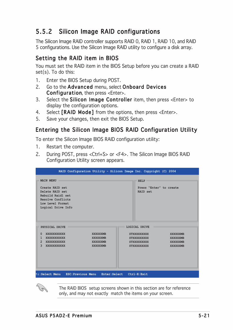
ASUS P5AD2-E PremiumASUS P5AD2-E PremiumASUS P5AD2-E PremiumASUS P5AD2-E PremiumASUS P5AD2-E Premium 5 -215 -215 -215 -215 -21
5.5.25.5.25.5.25.5.25.5.2 Silicon Image RAID configurationsSilicon Image RAID configurationsSilicon Image RAID configurationsSilicon Image RAID configurationsSilicon Image RAID configurations
The Silicon Image RAID controller supports RAID 0, RAID 1, RAID 10, and RAID5 configurations. Use the Silicon Image RAID utility to configure a disk array.
Setting the RAID item in BIOSSetting the RAID item in BIOSSetting the RAID item in BIOSSetting the RAID item in BIOSSetting the RAID item in BIOS
You must set the RAID item in the BIOS Setup before you can create a RAIDset(s). To do this:
1. Enter the BIOS Setup during POST.
2. Go to the Advanced Advanced Advanced Advanced Advanced menu, select Onboard DevicesOnboard DevicesOnboard DevicesOnboard DevicesOnboard DevicesConf igurat ionConf igurat ionConf igurat ionConf igurat ionConf igurat ion, then press <Enter>.
3. Select the S i l icon Image Contro l ler S i l icon Image Contro l ler S i l icon Image Contro l ler S i l icon Image Contro l ler S i l icon Image Contro l ler item, then press <Enter> todisplay the configuration options.
4. Select [RAID Mode] [RAID Mode] [RAID Mode] [RAID Mode] [RAID Mode] from the options, then press <Enter>.
5. Save your changes, then exit the BIOS Setup.
Entering the Sil icon Image BIOS RAID Configuration Util ityEntering the Sil icon Image BIOS RAID Configuration Util ityEntering the Sil icon Image BIOS RAID Configuration Util ityEntering the Sil icon Image BIOS RAID Configuration Util ityEntering the Sil icon Image BIOS RAID Configuration Util ity
To enter the Silicon Image BIOS RAID configuration utility:
1. Restart the computer.
2. During POST, press <Ctrl+S> or <F4>. The Silicon Image BIOS RAIDConfiguration Utility screen appears.
Create RAID setDelete RAID setRebuild Raid1 setResolve ConflictsLow Level FormatLogical Drive Info
RAID Configuration Utility - Silicon Image Inc. Copyright (C) 2004
↑↓↑↓↑↓↑↓↑↓ :Select Menu ESC:Previous Menu Enter:Select Ctrl-E:Exit
MAIN MENU
PHYSICAL DRIVE
0 XXXXXXXXXXX XXXXXXMB1 XXXXXXXXXXX XXXXXXMB2 XXXXXXXXXXX XXXXXXMB3 XXXXXXXXXXX XXXXXXMB
STXXXXXXXXX XXXXXXMBSTXXXXXXXXX XXXXXXMBSTXXXXXXXXX XXXXXXMBSTXXXXXXXXX XXXXXXMB
LOGICAL DRIVE
HELP
Press “Enter” to createRAID set
The RAID BIOS setup screens shown in this section are for referenceonly, and may not exactly match the items on your screen.

5 -225 -225 -225 -225 -22 Chapter 5 : Software supportChapter 5 : Software supportChapter 5 : Software supportChapter 5 : Software supportChapter 5 : Software support
On the upper right corner of the screen is the Help message box. Themessage describes the function of each menu item.
At the bottom of the screen is the legend box. The keys on the legend boxallow you to navigate through the setup menu options. The following liststhe keys found in the legend box and their corresponding functions.
↑↑↑↑↑ , , , , , ↓↓↓↓↓ : Select/Move to the next item
E S CE S CE S CE S CE S C : Previous Menu
EnterEnte rEnte rEnte rEnte r : Select
Ct r l -ECt r l -ECt r l -ECt r l -ECt r l -E : Exit
Create RAID setDelete RAID setRebuild Raid1 setResolve ConflictsLow Level FormatLogical Drive Info
RAID Configuration Utility - Silicon Image Inc. Copyright (C) 2004
↑↓↑↓↑↓↑↓↑↓ :Select Menu ESC:Previous Menu Enter:Select Ctrl-E:Exit
MAIN MENU
PHYSICAL DRIVE
0 XXXXXXXXXXX XXXXXXMB1 XXXXXXXXXXX XXXXXXMB2 XXXXXXXXXXX XXXXXXMB3 XXXXXXXXXXX XXXXXXMB
STXXXXXXXXX XXXXXXMBSTXXXXXXXXX XXXXXXMBSTXXXXXXXXX XXXXXXMBSTXXXXXXXXX XXXXXXMB
LOGICAL DRIVE
HELP
Press “Enter” to createRAID set
Legend boxLegend boxLegend boxLegend boxLegend box He l p sec t i onHe l p sec t i onHe l p sec t i onHe l p sec t i onHe l p sec t i on

ASUS P5AD2-E PremiumASUS P5AD2-E PremiumASUS P5AD2-E PremiumASUS P5AD2-E PremiumASUS P5AD2-E Premium 5 -235 -235 -235 -235 -23
Creating as RAID 0 set (Striped)Creating as RAID 0 set (Striped)Creating as RAID 0 set (Striped)Creating as RAID 0 set (Striped)Creating as RAID 0 set (Striped)
To create a RAID 0 set:
1. From the Silicon Imageconfiguration utilitymain menu, selectCreate RAID setCreate RAID setCreate RAID setCreate RAID setCreate RAID setthen press <Enter> todisplay an option menu.
2. Select RA ID 0RAID 0RAID 0RAID 0RAID 0, then press <Enter>.
3. Select your desiredmethod of configuration,then press <Enter>.
MAIN MENU
Auto configurationManual configuration
MAIN MENU
Create RAID setDelete RAID setRebuild Raid1 setResolve ConflictsLow Level FormatLogical Drive Info
RAID0RAID1RAID5RAID10
SPARE DRIVEJBOD
By default, Auto conf igurat ion Auto conf igurat ion Auto conf igurat ion Auto conf igurat ion Auto conf igurat ion sets the array stripe size to 64K andsets the logical drives based on the installed physical drives.
Manual conf igurat ionManual conf igurat ionManual conf igurat ionManual conf igurat ionManual conf igurat ion
a. When you select Manual conf igurat ionManual conf igurat ionManual conf igurat ionManual conf igurat ionManual conf igurat ion, a chunk size menuoption appears. Use the up or down arrow keys to select a chunksize appropriate to your drive usage, then press <Enter>.
MAIN MENU
Auto configurationManual configuration
chunk size4K8K16K32K64K128K
Auto conf igurat ionAuto conf igurat ionAuto conf igurat ionAuto conf igurat ionAuto conf igurat ion
When you select Auto conf igurat ionAuto conf igurat ionAuto conf igurat ionAuto conf igurat ionAuto conf igurat ion, a confirmation messageappears. Press <Y> to automatically create a RAID 0 set.
T IP : T I P : T I P : T I P : T I P : For server systems, use of a lower array block size is recommended.For multimedia computer systems used mainly for audio and video editing,a higher array block size is recommended for optimum performance.
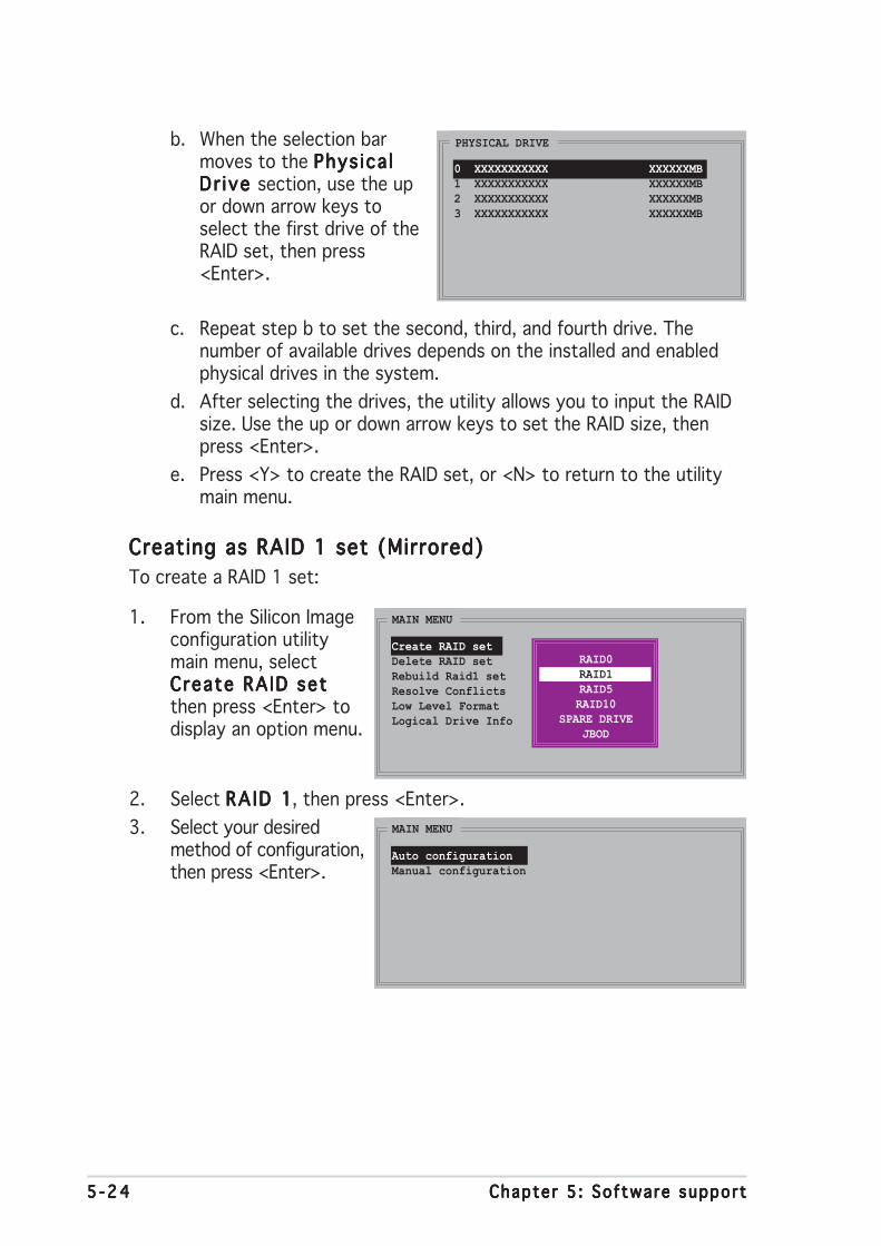
5 -245 -245 -245 -245 -24 Chapter 5 : Software supportChapter 5 : Software supportChapter 5 : Software supportChapter 5 : Software supportChapter 5 : Software support
b. When the selection barmoves to the Phys ica lPhys ica lPhys ica lPhys ica lPhys ica lDr ive Dr ive Dr ive Dr ive Dr ive section, use the upor down arrow keys toselect the first drive of theRAID set, then press<Enter>.
PHYSICAL DRIVE
0 XXXXXXXXXXX XXXXXXMB1 XXXXXXXXXXX XXXXXXMB2 XXXXXXXXXXX XXXXXXMB3 XXXXXXXXXXX XXXXXXMB
c. Repeat step b to set the second, third, and fourth drive. Thenumber of available drives depends on the installed and enabledphysical drives in the system.
d. After selecting the drives, the utility allows you to input the RAIDsize. Use the up or down arrow keys to set the RAID size, thenpress <Enter>.
e. Press <Y> to create the RAID set, or <N> to return to the utilitymain menu.
Creating as RAID 1 set (Mirrored)Creating as RAID 1 set (Mirrored)Creating as RAID 1 set (Mirrored)Creating as RAID 1 set (Mirrored)Creating as RAID 1 set (Mirrored)
To create a RAID 1 set:
1. From the Silicon Imageconfiguration utilitymain menu, selectCreate RAID setCreate RAID setCreate RAID setCreate RAID setCreate RAID setthen press <Enter> todisplay an option menu.
2. Select RA ID 1RAID 1RAID 1RAID 1RAID 1, then press <Enter>.
3. Select your desiredmethod of configuration,then press <Enter>.
MAIN MENU
Auto configurationManual configuration
MAIN MENU
Create RAID setDelete RAID setRebuild Raid1 setResolve ConflictsLow Level FormatLogical Drive Info
RAID0RAID1RAID5RAID10
SPARE DRIVEJBOD
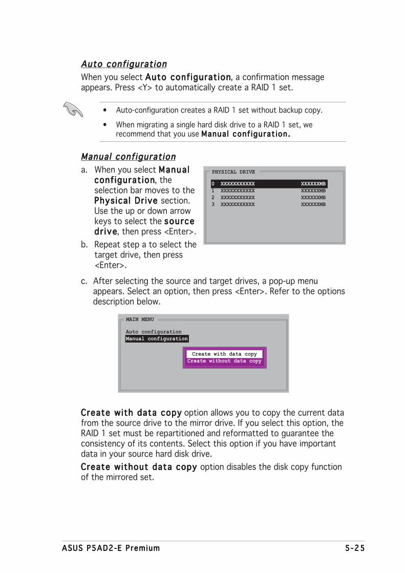
ASUS P5AD2-E PremiumASUS P5AD2-E PremiumASUS P5AD2-E PremiumASUS P5AD2-E PremiumASUS P5AD2-E Premium 5 -255 -255 -255 -255 -25
Auto conf igurat ionAuto conf igurat ionAuto conf igurat ionAuto conf igurat ionAuto conf igurat ion
When you select Auto conf igurat ionAuto conf igurat ionAuto conf igurat ionAuto conf igurat ionAuto conf igurat ion, a confirmation messageappears. Press <Y> to automatically create a RAID 1 set.
• Auto-configuration creates a RAID 1 set without backup copy.
• When migrating a single hard disk drive to a RAID 1 set, werecommend that you use Manua l conf igurat ion .Manua l conf igurat ion .Manua l conf igurat ion .Manua l conf igurat ion .Manua l conf igurat ion .
Manual conf igurat ionManual conf igurat ionManual conf igurat ionManual conf igurat ionManual conf igurat ion
a. When you select Manua lManua lManua lManua lManua lconf igurat ionconf igurat ionconf igurat ionconf igurat ionconf igurat ion, theselection bar moves to thePhys ica l Dr ive Phys ica l Dr ive Phys ica l Dr ive Phys ica l Dr ive Phys ica l Dr ive section.Use the up or down arrowkeys to select the sourcesourcesourcesourcesourcedr i vedr i vedr i vedr i vedr i ve, then press <Enter>.
b. Repeat step a to select thetarget drive, then press<Enter>.
c. After selecting the source and target drives, a pop-up menuappears. Select an option, then press <Enter>. Refer to the optionsdescription below.
MAIN MENU
Auto configurationManual configuration
Create with data copyCreate without data copy
Create with data copyCreate with data copyCreate with data copyCreate with data copyCreate with data copy option allows you to copy the current datafrom the source drive to the mirror drive. If you select this option, theRAID 1 set must be repartitioned and reformatted to guarantee theconsistency of its contents. Select this option if you have importantdata in your source hard disk drive.
Create without data copy Create without data copy Create without data copy Create without data copy Create without data copy option disables the disk copy functionof the mirrored set.
PHYSICAL DRIVE
0 XXXXXXXXXXX XXXXXXMB1 XXXXXXXXXXX XXXXXXMB2 XXXXXXXXXXX XXXXXXMB3 XXXXXXXXXXX XXXXXXMB
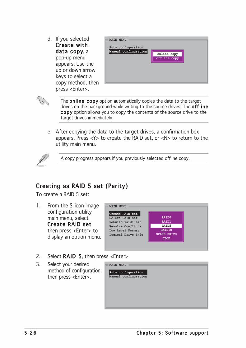
5 -265 -265 -265 -265 -26 Chapter 5 : Software supportChapter 5 : Software supportChapter 5 : Software supportChapter 5 : Software supportChapter 5 : Software support
d. If you selectedCreate withCreate withCreate withCreate withCreate withdata copydata copydata copydata copydata copy, apop-up menuappears. Use theup or down arrowkeys to select acopy method, thenpress <Enter>.
MAIN MENU
Auto configurationManual configuration
online copyoffline copy
The on l i ne copyon l i ne copyon l i ne copyon l i ne copyon l i ne copy option automatically copies the data to the targetdrives on the background while writing to the source drives. The o f f l i neo f f l i neo f f l i neo f f l i neo f f l i necopycopycopycopycopy option allows you to copy the contents of the source drive to thetarget drives immediately.
A copy progress appears if you previously selected offline copy.
e. After copying the data to the target drives, a confirmation boxappears. Press <Y> to create the RAID set, or <N> to return to theutility main menu.
Creating as RAID 5 set (Parity)Creating as RAID 5 set (Parity)Creating as RAID 5 set (Parity)Creating as RAID 5 set (Parity)Creating as RAID 5 set (Parity)
To create a RAID 5 set:
1. From the Silicon Imageconfiguration utilitymain menu, selectCreate RAID setCreate RAID setCreate RAID setCreate RAID setCreate RAID setthen press <Enter> todisplay an option menu.
2. Select RA ID 5RAID 5RAID 5RAID 5RAID 5, then press <Enter>.
3. Select your desiredmethod of configuration,then press <Enter>.
MAIN MENU
Auto configurationManual configuration
MAIN MENU
Create RAID setDelete RAID setRebuild Raid1 setResolve ConflictsLow Level FormatLogical Drive Info
RAID0RAID1RAID5RAID10
SPARE DRIVEJBOD

ASUS P5AD2-E PremiumASUS P5AD2-E PremiumASUS P5AD2-E PremiumASUS P5AD2-E PremiumASUS P5AD2-E Premium 5 -275 -275 -275 -275 -27
Auto conf igurat ionAuto conf igurat ionAuto conf igurat ionAuto conf igurat ionAuto conf igurat ion
When you select Auto conf igurat ionAuto conf igurat ionAuto conf igurat ionAuto conf igurat ionAuto conf igurat ion, the utility will require you tospecify the RAID size. Use the up or down arrow keys to set the RAIDsize, then press <Enter>.
After specifying the RAID size, press <Y> to automatically create aRAID 5 set, or <N> to return to the utility main menu.
Manual conf igurat ionManual conf igurat ionManual conf igurat ionManual conf igurat ionManual conf igurat ion
a. When you select Manual conf igurat ionManual conf igurat ionManual conf igurat ionManual conf igurat ionManual conf igurat ion, a chunk size menuoption appears. Use the up or down arrow keys to select a chunksize appropriate to your drive usage, then press <Enter>.
MAIN MENU
Auto configurationManual configuration
chunk size4K8K16K32K64K128K
T IP : T I P : T I P : T I P : T I P : For server systems, use of a lower array block size is recommended.For multimedia computer systems used mainly for audio and video editing,a higher array block size is recommended for optimum performance.
b. When the selection barmoves to the Phys ica lPhys ica lPhys ica lPhys ica lPhys ica lDr ive Dr ive Dr ive Dr ive Dr ive section, use the upor down arrow keys toselect the first drive of theRAID set, then press<Enter>.
PHYSICAL DRIVE
0 XXXXXXXXXXX XXXXXXMB1 XXXXXXXXXXX XXXXXXMB2 XXXXXXXXXXX XXXXXXMB3 XXXXXXXXXXX XXXXXXMB
c. Repeat step b to set the second, third, and fourth drive. Thenumber of available drives depends on the installed and enabledphysical drives in the system.
d. After selecting the drives, the utility allows you to input the RAIDsize. Use the up or down arrow keys to set the RAID size, thenpress <Enter>.
e. Press <Y> to create the RAID set, or <N> to return to the utilitymain menu.
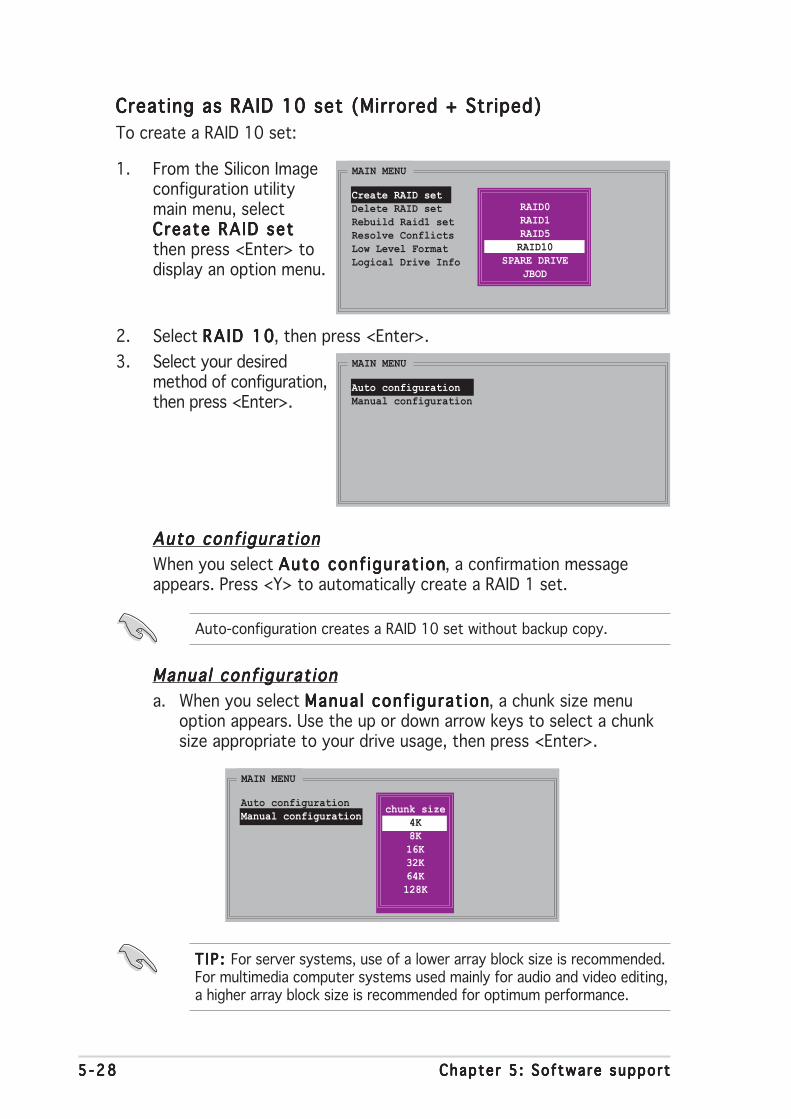
5 -285 -285 -285 -285 -28 Chapter 5 : Software supportChapter 5 : Software supportChapter 5 : Software supportChapter 5 : Software supportChapter 5 : Software support
Creating as RAID 10 set (Mirrored + Striped)Creating as RAID 10 set (Mirrored + Striped)Creating as RAID 10 set (Mirrored + Striped)Creating as RAID 10 set (Mirrored + Striped)Creating as RAID 10 set (Mirrored + Striped)
To create a RAID 10 set:
1. From the Silicon Imageconfiguration utilitymain menu, selectCreate RAID setCreate RAID setCreate RAID setCreate RAID setCreate RAID setthen press <Enter> todisplay an option menu.
2. Select RA ID 10RAID 10RAID 10RAID 10RAID 10, then press <Enter>.
3. Select your desiredmethod of configuration,then press <Enter>.
MAIN MENU
Auto configurationManual configuration
MAIN MENU
Create RAID setDelete RAID setRebuild Raid1 setResolve ConflictsLow Level FormatLogical Drive Info
RAID0RAID1RAID5RAID10
SPARE DRIVEJBOD
Auto conf igurat ionAuto conf igurat ionAuto conf igurat ionAuto conf igurat ionAuto conf igurat ion
When you select Auto conf igurat ionAuto conf igurat ionAuto conf igurat ionAuto conf igurat ionAuto conf igurat ion, a confirmation messageappears. Press <Y> to automatically create a RAID 1 set.
Auto-configuration creates a RAID 10 set without backup copy.
Manual conf igurat ionManual conf igurat ionManual conf igurat ionManual conf igurat ionManual conf igurat ion
a. When you select Manual conf igurat ionManual conf igurat ionManual conf igurat ionManual conf igurat ionManual conf igurat ion, a chunk size menuoption appears. Use the up or down arrow keys to select a chunksize appropriate to your drive usage, then press <Enter>.
MAIN MENU
Auto configurationManual configuration
chunk size4K8K16K32K64K128K
T IP : T I P : T I P : T I P : T I P : For server systems, use of a lower array block size is recommended.For multimedia computer systems used mainly for audio and video editing,a higher array block size is recommended for optimum performance.
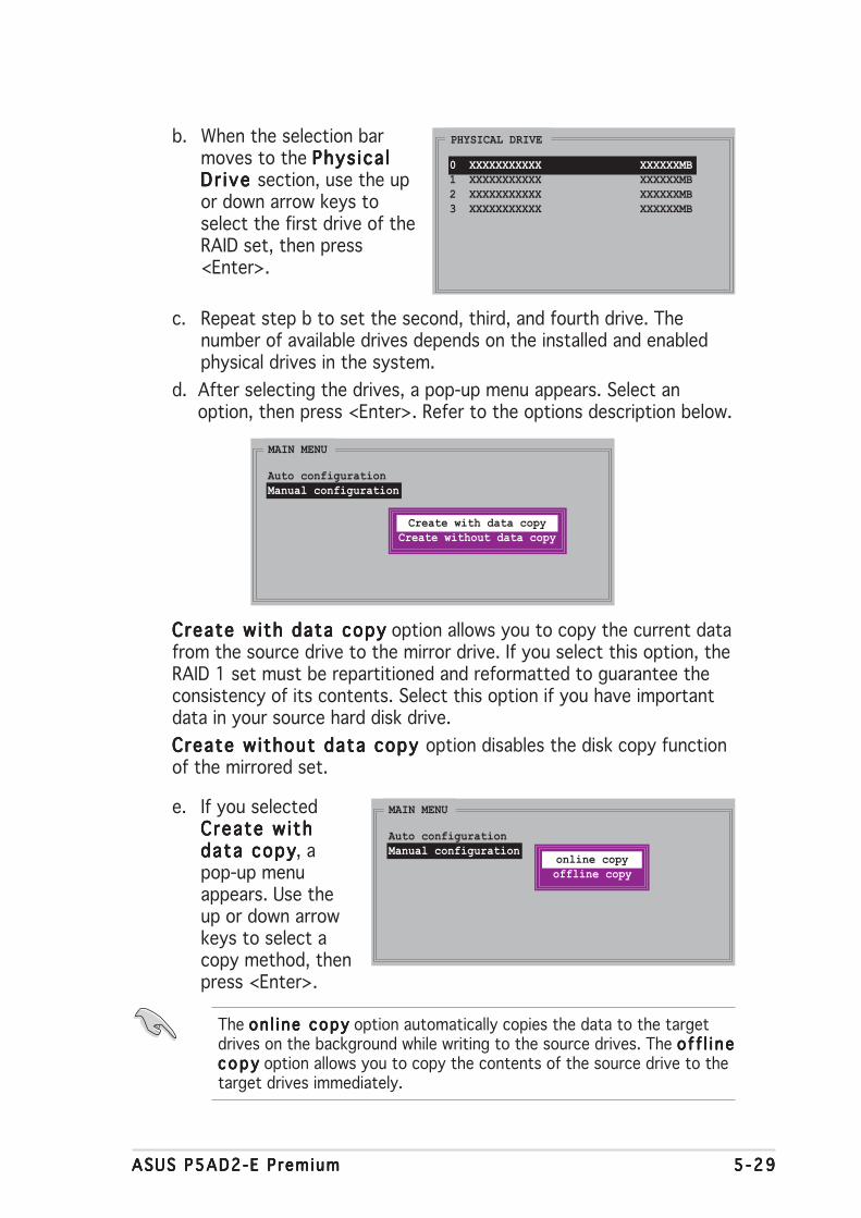
ASUS P5AD2-E PremiumASUS P5AD2-E PremiumASUS P5AD2-E PremiumASUS P5AD2-E PremiumASUS P5AD2-E Premium 5 -295 -295 -295 -295 -29
b. When the selection barmoves to the Phys ica lPhys ica lPhys ica lPhys ica lPhys ica lDr ive Dr ive Dr ive Dr ive Dr ive section, use the upor down arrow keys toselect the first drive of theRAID set, then press<Enter>.
PHYSICAL DRIVE
0 XXXXXXXXXXX XXXXXXMB1 XXXXXXXXXXX XXXXXXMB2 XXXXXXXXXXX XXXXXXMB3 XXXXXXXXXXX XXXXXXMB
c. Repeat step b to set the second, third, and fourth drive. Thenumber of available drives depends on the installed and enabledphysical drives in the system.
d. After selecting the drives, a pop-up menu appears. Select anoption, then press <Enter>. Refer to the options description below.
MAIN MENU
Auto configurationManual configuration
Create with data copyCreate without data copy
Create with data copyCreate with data copyCreate with data copyCreate with data copyCreate with data copy option allows you to copy the current datafrom the source drive to the mirror drive. If you select this option, theRAID 1 set must be repartitioned and reformatted to guarantee theconsistency of its contents. Select this option if you have importantdata in your source hard disk drive.
Create without data copy Create without data copy Create without data copy Create without data copy Create without data copy option disables the disk copy functionof the mirrored set.
e. If you selectedCreate withCreate withCreate withCreate withCreate withdata copydata copydata copydata copydata copy, apop-up menuappears. Use theup or down arrowkeys to select acopy method, thenpress <Enter>.
MAIN MENU
Auto configurationManual configuration
online copyoffline copy
The on l i ne copyon l i ne copyon l i ne copyon l i ne copyon l i ne copy option automatically copies the data to the targetdrives on the background while writing to the source drives. The o f f l i neo f f l i neo f f l i neo f f l i neo f f l i necopycopycopycopycopy option allows you to copy the contents of the source drive to thetarget drives immediately.

5 -305 -305 -305 -305 -30 Chapter 5 : Software supportChapter 5 : Software supportChapter 5 : Software supportChapter 5 : Software supportChapter 5 : Software support
A copy progress appears if you previously selected offline copy.
f. After copying the data to the target drives, a confirmation boxappears. Press <Y> to create the RAID set, or <N> to return to theutility main menu.
• For details on the Silicon Image SATARaid™ RAID configuration, referto the “Sil3114 User’s Manual” in the motherboard support CD.
• A RAID 5 configuration requires at least 1 GB of system memory and3 GHz processor core speed for optimum performance.
• You can only set the SATALink™ RAID 5 configuration using theSATALink™ SATA RAID Management Software.
• Make sure to install the Silicon Image SATA Link Sil 3114 driver andthe Silicon Image RAID 5 Array Management Utility before usingRAID 5 configuration. These are available from the support CD.
Sil icon Image Array Management SoftwareSil icon Image Array Management SoftwareSil icon Image Array Management SoftwareSil icon Image Array Management SoftwareSil icon Image Array Management Software
The Silicon Image Array Management Software is a Windows®-basedapplication that allows you to create a RAID set(s) in Windows® XPenvironment. This application is available from the support CD that camewith the motherboard package.
To launch the application from Windows® XP, click Sta r tSta r tSta r tSta r tSta r t, select A l lA l lA l lA l lA l lP rograms Programs Programs Programs Programs > S i l icon Image S i l icon Image S i l icon Image S i l icon Image S i l icon Image > Sam.Sam.Sam.Sam.Sam.
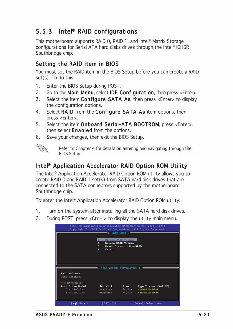
ASUS P5AD2-E PremiumASUS P5AD2-E PremiumASUS P5AD2-E PremiumASUS P5AD2-E PremiumASUS P5AD2-E Premium 5 -315 -315 -315 -315 -31
5.5.35.5.35.5.35.5.35.5.3 IntelIntelIntelIntelIntel®®®®® RAID configurations RAID configurations RAID configurations RAID configurations RAID configurations
This motherboard supports RAID 0, RAID 1, and Intel® Matrix Storageconfigurations for Serial ATA hard disks drives through the Intel® ICH6RSouthbridge chip.
Setting the RAID item in BIOSSetting the RAID item in BIOSSetting the RAID item in BIOSSetting the RAID item in BIOSSetting the RAID item in BIOS
You must set the RAID item in the BIOS Setup before you can create a RAIDset(s). To do this:
1. Enter the BIOS Setup during POST.
2. Go to the Main MenuMain MenuMain MenuMain MenuMain Menu, select IDE ConfigurationIDE ConfigurationIDE ConfigurationIDE ConfigurationIDE Configuration, then press <Enter>.
3. Select the item Conf igure SATA AsConf igure SATA AsConf igure SATA AsConf igure SATA AsConf igure SATA As, then press <Enter> to displaythe configuration options.
4. Select RA ID RA ID RA ID RA ID RA ID from the Conf igure SATA As Conf igure SATA As Conf igure SATA As Conf igure SATA As Conf igure SATA As item options, thenpress <Enter>.
5. Select the item Onboard Ser ia l -ATA BOOTROMOnboard Ser ia l -ATA BOOTROMOnboard Ser ia l -ATA BOOTROMOnboard Ser ia l -ATA BOOTROMOnboard Ser ia l -ATA BOOTROM, press <Enter>,then select Enab ledEnab ledEnab ledEnab ledEnab led from the options.
6. Save your changes, then exit the BIOS Setup.
Refer to Chapter 4 for details on entering and navigating through theBIOS Setup.
IntelIntelIntelIntelIntel®®®®® Application Accelerator RAID Option ROM Util ity Application Accelerator RAID Option ROM Util ity Application Accelerator RAID Option ROM Util ity Application Accelerator RAID Option ROM Util ity Application Accelerator RAID Option ROM Util ity
The Intel® Application Accelerator RAID Option ROM utility allows you tocreate RAID 0 and RAID 1 set(s) from SATA hard disk drives that areconnected to the SATA connectors supported by the motherboardSouthbridge chip.
To enter the Intel® Application Accelerator RAID Option ROM utility:
1. Turn on the system after installing all the SATA hard disk drives.
2. During POST, press <Ctrl+I> to display the utility main menu.
[ DISK/VOLUME INFORMATION ]
RAID Volumes:None defined.
Non-RAID Disks:
Port Drive Model Serial # Size Type/Status (Vol ID) 0 ST380013AS xxxxxxxx 74.5GB Non-RAID Disk 1 ST380013AS xxxxxxxx 74.5GB Non-RAID Disk
Intel(R) Application Accelerator RAID Option ROM v4.0.0.6211
Copyright(C) 2003-04 Intel Corporation. All Rights Reserved.
[ MAIN MENU ]
1. Create RAID Volume2. Delete RAID Volume3. Reset Disks to Non-RAID4. Exit
[ ]-Select[ ]-Select [ESC] Exit[ESC] Exit [Enter]-Select Menu[Enter]-Select Menu
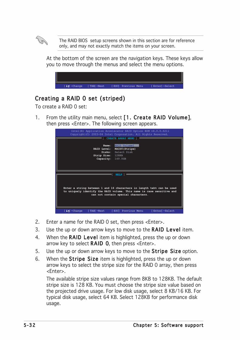
5 -325 -325 -325 -325 -32 Chapter 5 : Software supportChapter 5 : Software supportChapter 5 : Software supportChapter 5 : Software supportChapter 5 : Software support
The RAID BIOS setup screens shown in this section are for referenceonly, and may not exactly match the items on your screen.
At the bottom of the screen are the navigation keys. These keys allowyou to move through the menus and select the menu options.
[ ]-Change[ ]-Change [TAB]-Next[TAB]-Next [ESC] Previous Menu[ESC] Previous Menu [Enter]-Select[Enter]-Select
Creating a RAID 0 set (striped)Creating a RAID 0 set (striped)Creating a RAID 0 set (striped)Creating a RAID 0 set (striped)Creating a RAID 0 set (striped)
To create a RAID 0 set:
1. From the utility main menu, select [1. Create RAID Volume][1. Create RAID Volume][1. Create RAID Volume][1. Create RAID Volume][1. Create RAID Volume],then press <Enter>. The following screen appears.
[ HELP ]
Enter a string between 1 and 16 characters in length taht can be usedto uniquely identify the RAID volume. This name is case sensitive and
can not contain special characters.
Intel(R) Application Accelerator RAID Option ROM v4.0.0.6211
Copyright(C) 2003-04 Intel Corporation. All Rights Reserved.
[ CREATE ARRAY MENU ]
Name: RAID_Volume1RAID Level: RAID0(Stripe) Disks: Select DiskStrip Size: 128KB Capacity: 149.0GB
[ ]-Change[ ]-Change [TAB]-Next[TAB]-Next [ESC] Previous Menu[ESC] Previous Menu [Enter]-Select[Enter]-Select
2. Enter a name for the RAID 0 set, then press <Enter>.
3. Use the up or down arrow keys to move to the RAID Leve l RAID Leve l RAID Leve l RAID Leve l RAID Leve l item.
4. When the RAID Leve l RAID Leve l RAID Leve l RAID Leve l RAID Leve l item is highlighted, press the up or downarrow key to select RA ID 0RAID 0RAID 0RAID 0RAID 0, then press <Enter>.
5. Use the up or down arrow keys to move to the Str ipe S izeStr ipe S izeStr ipe S izeStr ipe S izeStr ipe S ize option.
6. When the Str ipe S ize Str ipe S ize Str ipe S ize Str ipe S ize Str ipe S ize item is highlighted, press the up or downarrow keys to select the stripe size for the RAID 0 array, then press<Enter>.
The available stripe size values range from 8KB to 128KB. The defaultstripe size is 128 KB. You must choose the stripe size value based onthe projected drive usage. For low disk usage, select 8 KB/16 KB. Fortypical disk usage, select 64 KB. Select 128KB for performance diskusage.
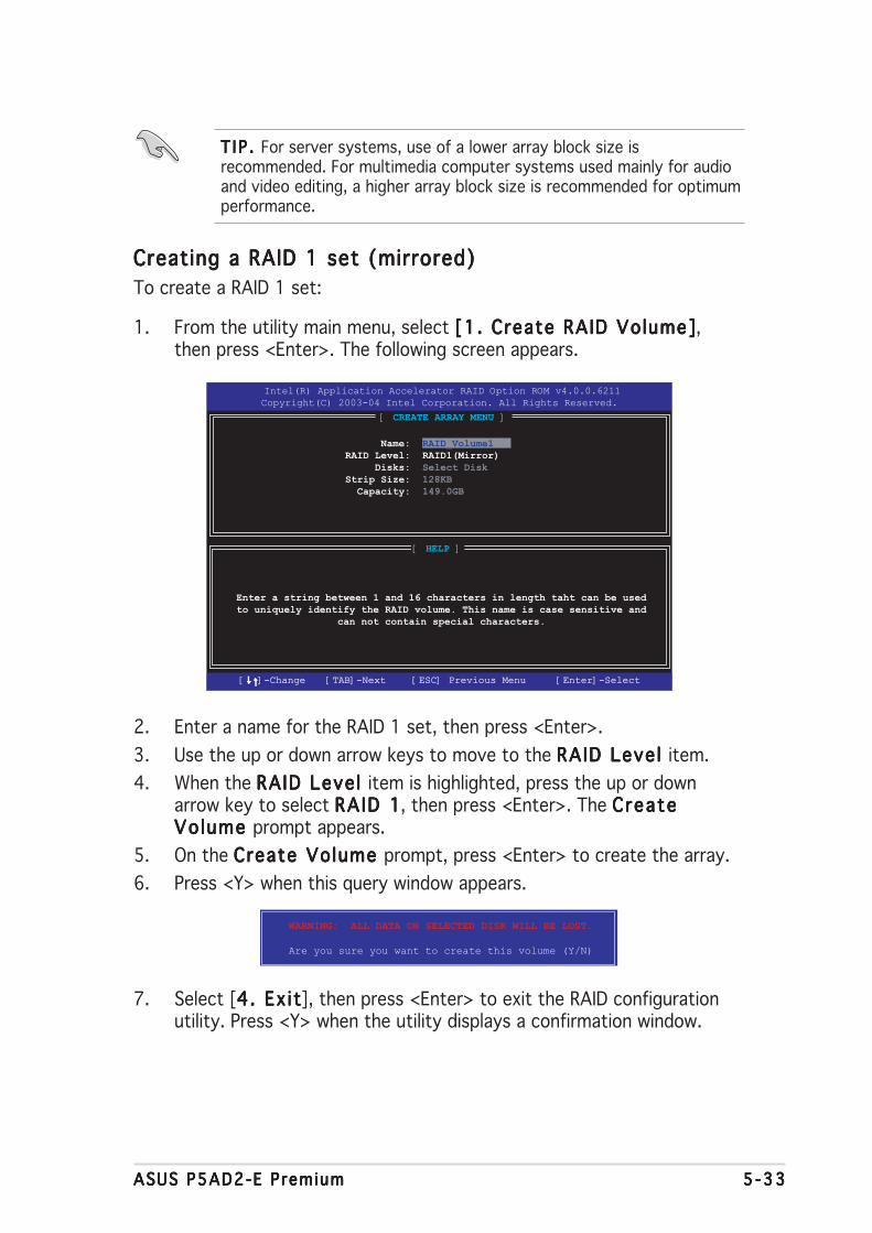
ASUS P5AD2-E PremiumASUS P5AD2-E PremiumASUS P5AD2-E PremiumASUS P5AD2-E PremiumASUS P5AD2-E Premium 5 -335 -335 -335 -335 -33
T I P . T I P . T I P . T I P . T I P . For server systems, use of a lower array block size isrecommended. For multimedia computer systems used mainly for audioand video editing, a higher array block size is recommended for optimumperformance.
Creating a RAID 1 set (mirrored)Creating a RAID 1 set (mirrored)Creating a RAID 1 set (mirrored)Creating a RAID 1 set (mirrored)Creating a RAID 1 set (mirrored)
To create a RAID 1 set:
1. From the utility main menu, select [1. Create RAID Volume][1. Create RAID Volume][1. Create RAID Volume][1. Create RAID Volume][1. Create RAID Volume],then press <Enter>. The following screen appears.
[ HELP ]
Enter a string between 1 and 16 characters in length taht can be usedto uniquely identify the RAID volume. This name is case sensitive and
can not contain special characters.
Intel(R) Application Accelerator RAID Option ROM v4.0.0.6211
Copyright(C) 2003-04 Intel Corporation. All Rights Reserved.
[ CREATE ARRAY MENU ]
Name: RAID_Volume1RAID Level: RAID1(Mirror) Disks: Select DiskStrip Size: 128KB Capacity: 149.0GB
[ ]-Change[ ]-Change [TAB]-Next[TAB]-Next [ESC] Previous Menu[ESC] Previous Menu [Enter]-Select[Enter]-Select
2. Enter a name for the RAID 1 set, then press <Enter>.
3. Use the up or down arrow keys to move to the RAID Leve l RAID Leve l RAID Leve l RAID Leve l RAID Leve l item.
4. When the RAID Leve l RAID Leve l RAID Leve l RAID Leve l RAID Leve l item is highlighted, press the up or downarrow key to select RA ID 1RAID 1RAID 1RAID 1RAID 1, then press <Enter>. The CreateCreateCreateCreateCreateVo lume Vo lume Vo lume Vo lume Vo lume prompt appears.
5. On the Create Volume Create Volume Create Volume Create Volume Create Volume prompt, press <Enter> to create the array.
6. Press <Y> when this query window appears.
WARNING: ALL DATA ON SELECTED DISK WILL BE LOST.
Are you sure you want to create this volume (Y/N)
7. Select [4 . Ex i t4 . Ex i t4 . Ex i t4 . Ex i t4 . Ex i t], then press <Enter> to exit the RAID configurationutility. Press <Y> when the utility displays a confirmation window.
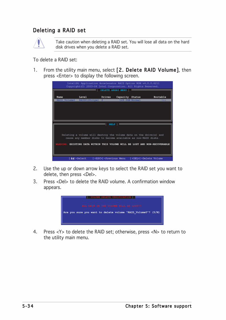
5 -345 -345 -345 -345 -34 Chapter 5 : Software supportChapter 5 : Software supportChapter 5 : Software supportChapter 5 : Software supportChapter 5 : Software support
Deleting a RAID setDeleting a RAID setDeleting a RAID setDeleting a RAID setDeleting a RAID set
Take caution when deleting a RAID set. You will lose all data on the harddisk drives when you delete a RAID set.
To delete a RAID set:
1. From the utility main menu, select [2. Delete RAID Volume][2. Delete RAID Volume][2. Delete RAID Volume][2. Delete RAID Volume][2. Delete RAID Volume], thenpress <Enter> to display the following screen.
[ HELP ]
Deleting a volume will destroy the volume data on the drive(s) andcause any member disks to become available as non-RAID disks.
WARNING: EXISTING DATA WITHIN THIS VOLUME WILL BE LOST AND NON-RECOVERABLE
Intel(R) Application Accelerator RAID Option ROM v4.0.0.6211
Copyright(C) 2003-04 Intel Corporation. All Rights Reserved.
[ DELETE ARRAY MENU ]
[ ]-Select [ ]-Select [<ESC>]-Previous Menu[<ESC>]-Previous Menu [<DEL>]-Delete Volume[<DEL>]-Delete Volume
Name Level Drives Capacity Status BootableRAID_Volume1 RAID0(Stripe) 2 149.0GB Normal Yes
2. Use the up or down arrow keys to select the RAID set you want todelete, then press <Del>.
3. Press <Del> to delete the RAID volume. A confirmation windowappears.
ALL DATA IN THE VOLUME WILL BE LOST!!
Are you sure you want to delete volume "RAID_Volume0"? (Y/N)
[ VOLUME DELETE VERIFICATION ]
4. Press <Y> to delete the RAID set; otherwise, press <N> to return tothe utility main menu.

ASUS P5AD2-E PremiumASUS P5AD2-E PremiumASUS P5AD2-E PremiumASUS P5AD2-E PremiumASUS P5AD2-E Premium 5 -355 -355 -355 -355 -35
Resetting a RAID set hard disk drivesResetting a RAID set hard disk drivesResetting a RAID set hard disk drivesResetting a RAID set hard disk drivesResetting a RAID set hard disk drives
Take caution before you reset a RAID volume HDD to non-RAID. Resettinga RAID volume HDD deletes all internal RAID structure on the drive.
To reset a RAID set hard disk drive:
1. From the utility main menu, select [3. Reset Disks to Non-RAID][3. Reset Disks to Non-RAID][3. Reset Disks to Non-RAID][3. Reset Disks to Non-RAID][3. Reset Disks to Non-RAID],then press <Enter> to display the following screen.
Resetting RAID data will remove the internal RAID structuresfrom the selected RAID disks. By removing these structuresthe drive will revert back to a Non-RAID disk.
[ RESET RAID DATA ]
WARNING: Resetting a disk causes all data on the disk to be lost.
Port Drive Model Serial # Size Status 0 STXXXXXXXXX XXXXXXXX XX.0GB Member Disk 1 STXXXXXXXXX XXXXXXXX XX.0GB Member Disk
Select the disk that should be reset
[ ]-Previous/Next[ ]-Previous/Next [Space]-Selects [Space]-Selects [Enter]-Selection Complete[Enter]-Selection Complete
2. Use the up or down arrow keys to highlight the RAID set drive youwant to reset, then press <Space> to select.
3. Press <Enter> to reset the RAID set drive. A confirmation windowappears.
4. Press <Y> to reset the drive; otherwise, press <N> to return to theutility main menu.
5. Follow steps 2 to 4 to select and reset other RAID set drives.

5 -365 -365 -365 -365 -36 Chapter 5 : Software supportChapter 5 : Software supportChapter 5 : Software supportChapter 5 : Software supportChapter 5 : Software support
The navigation keys on the bottom of the screen allow you to movethrough the menus, select from the menu options, or exit the utility.
5.5.45.5.45.5.45.5.45.5.4 ITEITEITEITEITE®®®®® 8212F RAID configurations 8212F RAID configurations 8212F RAID configurations 8212F RAID configurations 8212F RAID configurations
The ITE® 8212F IDE RAID controller supports RAID 0, RAID 1, RAID 0+1 andJBOD configurations. Use the IT8212 Setup Utility to create a disk array.
Setting the IDE RAID item in BIOSSetting the IDE RAID item in BIOSSetting the IDE RAID item in BIOSSetting the IDE RAID item in BIOSSetting the IDE RAID item in BIOS
You must set the IDE RAID item in the BIOS Setup before you can create anIDE RAID set(s). To do this:
1. Enter the BIOS Setup during POST.
2. Go to the Advance Advance Advance Advance Advance MenuMenuMenuMenuMenu, select Onboard DevicesOnboard DevicesOnboard DevicesOnboard DevicesOnboard DevicesConf igurat ionConf igurat ionConf igurat ionConf igurat ionConf igurat ion, then press <Enter>.
3. Select the item ITE8212F Contro l lerITE8212F Contro l lerITE8212F Contro l lerITE8212F Contro l lerITE8212F Contro l ler, press <Enter>, then selectRAID Mode RAID Mode RAID Mode RAID Mode RAID Mode from the configuration options.
You can not enter the ITE® 8212F Setup Utility when you set theITE8212F Contro l le r ITE8212F Contro l le r ITE8212F Contro l le r ITE8212F Contro l le r ITE8212F Contro l le r option to [IDE Mode] or [Disabled].
5. Save your changes, then exit the BIOS Setup.
ITEITEITEITEITE®®®®® 8212F Setup Util ity 8212F Setup Util ity 8212F Setup Util ity 8212F Setup Util ity 8212F Setup Util ity
To enter the ITE® 8212F Setup Utility:
1. Restart the computer. During POST, the ITE8212F controllerautomatically scans for IDE devices attached to the IDE RAIDconnectors.
2. When prompted, press <Ctrl+F> or <Ctrl+E> to display the utility mainmenu.
Auto Configuration...........[ 1 ]
Define RAID..................[ 2 ]
Delete RAID..................[ 3 ]
Rebuild RAID.................[ 4 ]
RAID Card Configuration......[ 5 ]
IT8212 Setup Utility (C)Copyright 2002-2004 ITE, Inc.
[1]..[5] Select [ESC] Exit
[MAIN MENU]
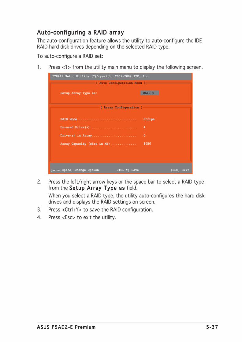
ASUS P5AD2-E PremiumASUS P5AD2-E PremiumASUS P5AD2-E PremiumASUS P5AD2-E PremiumASUS P5AD2-E Premium 5 -375 -375 -375 -375 -37
RAID Mode................................ Stripe
Un-used Drive(s)......................... 4
Drive(s) in Array........................ 0
Array Capacity (size in MB).............. 8056
IT8212 Setup Utility (C)Copyright 2002-2004 ITE, Inc.
[ Auto Configuration Menu ]
[ Array Configuration ]
Setup Array Type as: RAID 0
[→→→→→,←←←←←,Space] Change Option [CTRL-Y] Save [ESC] Exit
Auto-configuring a RAID arrayAuto-configuring a RAID arrayAuto-configuring a RAID arrayAuto-configuring a RAID arrayAuto-configuring a RAID array
The auto-configuration feature allows the utility to auto-configure the IDERAID hard disk drives depending on the selected RAID type.
To auto-configure a RAID set:
1. Press <1> from the utility main menu to display the following screen.
2. Press the left/right arrow keys or the space bar to select a RAID typefrom the Setup Array Type as Setup Array Type as Setup Array Type as Setup Array Type as Setup Array Type as field.
When you select a RAID type, the utility auto-configures the hard diskdrives and displays the RAID settings on screen.
3. Press <Ctrl+Y> to save the RAID configuration.
4. Press <Esc> to exit the utility.

5 -385 -385 -385 -385 -38 Chapter 5 : Software supportChapter 5 : Software supportChapter 5 : Software supportChapter 5 : Software supportChapter 5 : Software support
IT8212 Setup Utility (C)Copyright 2002-2004 ITE, Inc.
[ Define RAID Menu ]
Array No Array Mode Drive No Size(MB) Status
Array 0 ---- ---- ----- -----
Array 1 ---- ---- ----- -----
Array 2 ---- ---- ----- -----
Array 3 ---- ---- ----- -----
∗∗∗∗∗ : Capacity (GB) ♦ ♦ ♦ ♦ ♦ : Bootable Array[↑↑↑↑↑] Up [↓↓↓↓↓] Down [Space] Boot Array [Enter] Select [ESC] Exit
Defining a RAID arrayDefining a RAID arrayDefining a RAID arrayDefining a RAID arrayDefining a RAID array
This option allows you to define the RAID set(s).
To define a RAID set(s):
1. Press <2> from utility main menu. The following screen appears.
2. Press the up/down arrow keys or the space bar to select a RAID setyou want to define, then press <Enter>.
IT8212 Setup Utility (C)Copyright 2002-2004 ITE, Inc.
[ Define RAID Sub-Menu ]
∗∗∗∗∗ : Capacity (GB)[↑↑↑↑↑] Up [↓↓↓↓↓] Down [Space] Change Option [Ctrl-Y] Save [ESC] Exit
Channel ID Drive Name Size(MB) AssignmentPri/D0 XXXXXXXXXXXXXX XXXXXX Y
Pri/D1 XXXXXXXXXXXXXX XXXXXX Y
Sec/D0 XXXXXXXXXXXXXX XXXXXX Y
Sec/D1 XXXXXXXXXXXXXX XXXXXX Y
[ Drive Assignments]
Array No Array Mode Drive No Status
Array 0 Stripe 4 Functional
Block Size: 64KB
3. Press the up/down arrow keys to move through the RAID set values.
4. Press the Space bar to adjust the RAID set values.
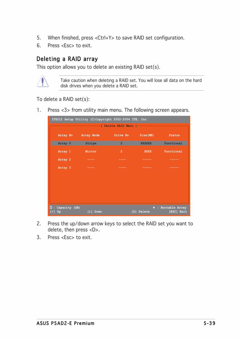
ASUS P5AD2-E PremiumASUS P5AD2-E PremiumASUS P5AD2-E PremiumASUS P5AD2-E PremiumASUS P5AD2-E Premium 5 -395 -395 -395 -395 -39
5. When finished, press <Ctrl+Y> to save RAID set configuration.
6. Press <Esc> to exit.
Deleting a RAID arrayDeleting a RAID arrayDeleting a RAID arrayDeleting a RAID arrayDeleting a RAID array
This option allows you to delete an existing RAID set(s).
Take caution when deleting a RAID set. You will lose all data on the harddisk drives when you delete a RAID set.
To delete a RAID set(s):
1. Press <3> from utility main menu. The following screen appears.
IT8212 Setup Utility (C)Copyright 2002-2004 ITE, Inc.
[ Delete RAID Menu ]
Array No Array Mode Drive No Size(MB) Status
Array 0 Stripe 2 XXXXXX Functional
Array 1 Mirror 2 XXXX Functional
Array 2 ---- ---- ----- -----
Array 3 ---- ---- ----- -----
∗∗∗∗∗ : Capacity (GB) ♦ ♦ ♦ ♦ ♦ : Bootable Array[↑↑↑↑↑] Up [↓↓↓↓↓] Down [D] Delete [ESC] Exit
2. Press the up/down arrow keys to select the RAID set you want todelete, then press <D>.
3. Press <Esc> to exit.
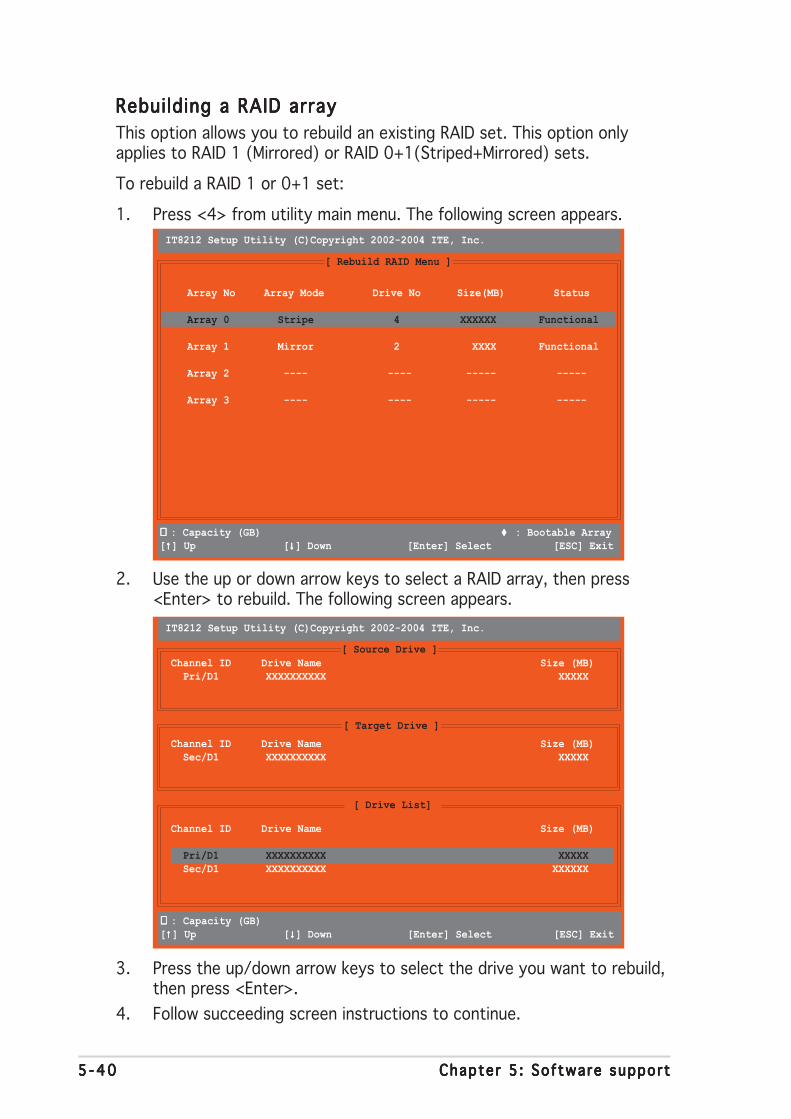
5 -405 -405 -405 -405 -40 Chapter 5 : Software supportChapter 5 : Software supportChapter 5 : Software supportChapter 5 : Software supportChapter 5 : Software support
IT8212 Setup Utility (C)Copyright 2002-2004 ITE, Inc.
[ Rebuild RAID Menu ]
Array No Array Mode Drive No Size(MB) Status
Array 0 Stripe 4 XXXXXX Functional
Array 1 Mirror 2 XXXX Functional
Array 2 ---- ---- ----- -----
Array 3 ---- ---- ----- -----
∗∗∗∗∗ : Capacity (GB) ♦ ♦ ♦ ♦ ♦ : Bootable Array[↑↑↑↑↑] Up [↓↓↓↓↓] Down [Enter] Select [ESC] Exit
Rebuilding a RAID arrayRebuilding a RAID arrayRebuilding a RAID arrayRebuilding a RAID arrayRebuilding a RAID array
This option allows you to rebuild an existing RAID set. This option onlyapplies to RAID 1 (Mirrored) or RAID 0+1(Striped+Mirrored) sets.
To rebuild a RAID 1 or 0+1 set:
1. Press <4> from utility main menu. The following screen appears.
2. Use the up or down arrow keys to select a RAID array, then press<Enter> to rebuild. The following screen appears.
IT8212 Setup Utility (C)Copyright 2002-2004 ITE, Inc.
[ Source Drive ]
[ Target Drive ]
Channel ID Drive Name Size (MB) Pri/D1 XXXXXXXXXX XXXXX
∗∗∗∗∗ : Capacity (GB)[↑↑↑↑↑] Up [↓↓↓↓↓] Down [Enter] Select [ESC] Exit
[ Drive List]
Channel ID Drive Name Size (MB) Sec/D1 XXXXXXXXXX XXXXX
Channel ID Drive Name Size (MB)
Pri/D1 XXXXXXXXXX XXXXX Sec/D1 XXXXXXXXXX XXXXXX
3. Press the up/down arrow keys to select the drive you want to rebuild,then press <Enter>.
4. Follow succeeding screen instructions to continue.

ASUS P5AD2-E PremiumASUS P5AD2-E PremiumASUS P5AD2-E PremiumASUS P5AD2-E PremiumASUS P5AD2-E Premium 5 -415 -415 -415 -415 -41
Channel 0 Interrupt: B I/P Port: 0000AC00
Channel 1 Interrupt: B I/P Port: 0000A800
IT8212 Setup Utility (C)Copyright 2002-2004 ITE, Inc.
[ RAID Card Configuration ]
[ RAID Card Resource ]
Auto-Rebuild: Enable
∗∗∗∗∗ : Capacity (GB) Drive Mode: P = PIO, D = DMA, U = UDMA[→→→→→,←←←←←,Space] Change Option [ESC] Exit
Channel Size Drive ID Drive Name (MB) Array No ModePri/D0 XXXXXXXXXXXXXX XXXXXX Array 0 U5
Pri/D1 XXXXXXXXXXXXXX XXXXXX Array 0 U2
Sec/D0 XXXXXXXXXXXXXX XXXXXX Array 0 U4
Sec/D1 XXXXXXXXXXXXXX XXXXXX Array 0 U6
[ Drive Status ]
Viewing your RAID configurationViewing your RAID configurationViewing your RAID configurationViewing your RAID configurationViewing your RAID configuration
This option allows you to view the system RAID configuration and RAIDresources. You can also enable or disable the Auto-Rebuild function fromthis menu.
To view your RAID configuration:
1. Press <5> from utility main menu. The following screen appears.
2. View your RAID configuration from this menu, then press <Esc> toexit the utility.
To enable/disable the Auto-Rebuild feature:
1. Use the left/right arrow keys or the space bar to enable or disablethe Auto-Rebui ldAuto-Rebui ldAuto-Rebui ldAuto-Rebui ldAuto-Rebui ld item.
2. Press <Esc> to exit the utility.

5 -425 -425 -425 -425 -42 Chapter 5 : Software supportChapter 5 : Software supportChapter 5 : Software supportChapter 5 : Software supportChapter 5 : Software support
5.6 Creating a RAID driver disk
A floppy disk with the RAID driver is required when installing Windows®
2000/XP operating system on a hard disk drive that is included in a RAIDset. You can create a RAID driver disk in DOS (using the Makediskapplication in the support CD) or in Windows® environment.
To create a RAID driver disk in DOS environment:
1. Place the motherboard support CD in the optical drive.
2. Restart the computer, then enter the BIOS Setup.
3. Select the optical drive as the first boot priority to boot from thesupport CD. Save your changes, then exit the BIOS Setup.
4. Restart the computer.
5. Press any key when prompted to boot from CD.
The Makedisk menu appears.
6. Place a blank, high-density floppy disk to the floppy disk drive, thenpress <4>. The following message displays on screen.
Loading FreeDOS FAT KERNEL GO!
Press any key to boot from CDROM...
1) Make ICH6R SATA driver disk
2) Make Sil3114 SATA/RAID driver disk
3) Make ITE RAID driver disk
4) Format floppy disk
5) FreeDOS command prompt
Please choose 1 ~ 5
7. Press <Enter> to format the floppy disk.
8. When finished, select the type of RAID driver disk you want to createby typing the number preceding the option, then press <Enter>. Forexample, if you want to create an ICH6R SATA RAID driver disk, press<1>. The following message appears on screen.
Insert new diskette for drive B:\
and press ENTER when ready...
Please insert your formatted floppy to drive B:\
Press a key to continue.

ASUS P5AD2-E PremiumASUS P5AD2-E PremiumASUS P5AD2-E PremiumASUS P5AD2-E PremiumASUS P5AD2-E Premium 5 -435 -435 -435 -435 -43
3. Insert a formatted high-density floppy disk to the floppy disk drive.
4. Follow screen instructions to complete the process.
5. After creating a RAID driver disk, eject the floppy disk, thenwrite-protect it to prevent computer virus infection.
To install the RAID driver:
1. Install an operating system to the selected hard disk drive. Duringinstallation, the computer prompts you to press the F 6F 6F 6F 6F 6 key if you areinstalling a third-party SCSI or RAID driver.
2. Press <F6>, then insert the RAID driver disk to the floppy disk drive.
3. Follow screen instructions to install the RAID drivers.
Refer to section “5.2.2 Drivers menu” for details.
9. The RAID drivers are copied to the floppy disk. After creating a RAIDdriver disk, eject the floppy disk, then write-protect it to preventcomputer virus infection.
10. Press any key to return to the Makedisk menu.
To create a RAID driver disk from Windows® environment:
1. Place the motherboard support CD in the optical drive.
2. When the Dr ivers Dr ivers Dr ivers Dr ivers Dr ivers menu appears, select the RAID driver disk you wishto create:
• Click Make ITE8212 Dr iver Disk Make ITE8212 Dr iver Disk Make ITE8212 Dr iver Disk Make ITE8212 Dr iver Disk Make ITE8212 Dr iver Disk to create an ITE® 8212F RAIDdriver disk.
• Click Make Si l icon Image RAID Dr iver DiskMake Si l icon Image RAID Dr iver DiskMake Si l icon Image RAID Dr iver DiskMake Si l icon Image RAID Dr iver DiskMake Si l icon Image RAID Dr iver Disk to create a SiliconImage SATARaid™ RAID driver disk
O rO rO rO rO r
Browse the contents of the support CD to locate the driver diskutility:
• ITE8212 RAID Dr iver DiskITE8212 RAID Dr iver DiskITE8212 RAID Dr iver DiskITE8212 RAID Dr iver DiskITE8212 RAID Dr iver Disk:
\Drivers\ITE8212\MakeDisk
• Si l icon Image RAID Dr iver DiskSi l icon Image RAID Dr iver DiskSi l icon Image RAID Dr iver DiskSi l icon Image RAID Dr iver DiskSi l icon Image RAID Dr iver Disk:\Drivers\Sil3114\RAID_Disk
• I n te lI n te lI n te lI n te lI n te l® RAID Dr iver D iskRAID Dr iver D iskRAID Dr iver D iskRAID Dr iver D iskRAID Dr iver D isk:\Drivers\Chipset\Intel\IAA\F6 Install Floppy\F6flpy32

5 -445 -445 -445 -445 -44 Chapter 5 : Software supportChapter 5 : Software supportChapter 5 : Software supportChapter 5 : Software supportChapter 5 : Software support

ACPU features
The Appendix describes the CPUfeatures that the motherboardsupports.

ASUS P5AD2-E PremiumASUS P5AD2-E PremiumASUS P5AD2-E PremiumASUS P5AD2-E PremiumASUS P5AD2-E Premium
Chapter summary AA.1 Intel® EM64T ........................................................................ A-1
A.2 Enhanced Intel SpeedStep® Technology (EIST) .................... A-1
A.3 Intel® Hyper-Threading Technology ...................................... A-3

ASUS P5AD2-E PremiumASUS P5AD2-E PremiumASUS P5AD2-E PremiumASUS P5AD2-E PremiumASUS P5AD2-E Premium
A.1 Intel® EM64T
• The motherboard is fully compatible with Intel® Pentium® 4 LGA775processors running on 32-bit operating systems.
• The motherboard comes with a BIOS file that supports EM64T. Youcan download the latest BIOS file from the ASUS website(www.asus.com/support/download/) if you need to update the BIOSfile. See Chapter 4 for details.
• Visit www.intel.com for more information on the EM64T feature.
• Visit www.microsoft.com for more information on Windows® 64-bit OS.
Using the IntelUsing the IntelUsing the IntelUsing the IntelUsing the Intel®®®®® EM64T feature EM64T feature EM64T feature EM64T feature EM64T feature
To use the Intel® EM64T feature:
1. Install an Intel® Pentium® 4 CPU that supports the Intel® EM64T.
2. Install a 64-bit operating system (Windows® XP Professional x64Edition or Windows® Server 2003 x64 Edition).
3. Install the 64-bit drivers for the motherboard components and devicesfrom the support CD.
4. Install the 64-bit drivers for expansion cards or add-on devices, if any.
Refer to the expansion card or add-on device(s) documentation, or visitthe related website, to verify if the card/device supports a 64-bit system.
A.2 Enhanced Intel SpeedStep®
Technology (EIST)
• The motherboard comes with a BIOS file that supports EIST. You candownload the latest BIOS file from the ASUS website(www.asus.com/support/download/) if you need to update theBIOS. See Chapter 4 for details.
• Visit www.intel.com for more information on the EIST feature.
A.2.1A.2.1A.2.1A.2.1A.2.1 System requirementsSystem requirementsSystem requirementsSystem requirementsSystem requirements
Before using EIST, check your system if it meets the followingrequirements:
• Intel® Pentium® 4 processor with EIST support
• BIOS file with EIST support
• Operating system with EIST support (Windows® XP SP2/Windows®
Server 2003 SP1/Linux 2.6 kernel or later versions)

A - 2A - 2A - 2A - 2A - 2 Append ix : CPU featuresAppend ix : CPU featuresAppend ix : CPU featuresAppend ix : CPU featuresAppend ix : CPU features
A.2.2A.2.2A.2.2A.2.2A.2.2 Using the EISTUsing the EISTUsing the EISTUsing the EISTUsing the EIST
To use the EIST feature:
1. Turn on the computer, then enter the BIOS Setup.
2. Go to the Advanced MenuAdvanced MenuAdvanced MenuAdvanced MenuAdvanced Menu, highlight CPU ConfigurationCPU ConfigurationCPU ConfigurationCPU ConfigurationCPU Configuration,then press <Enter>.
3. Set the Intel(R) SpeedStep TechnologyIntel(R) SpeedStep TechnologyIntel(R) SpeedStep TechnologyIntel(R) SpeedStep TechnologyIntel(R) SpeedStep Technology item to [Automatic],then press <Enter>. See page 4-26 for details.
4. Press <F10> to save your changes and exit the BIOS setup.
5. After the computer restarts, right click on a blank space on the desktop,then select Properties Properties Properties Properties Properties from the pop-up menu.
6. When the Display PropertiesDisplay PropertiesDisplay PropertiesDisplay PropertiesDisplay Propertieswindow appears, click theScreen Saver Screen Saver Screen Saver Screen Saver Screen Saver tab.
7. Click the Power Power Power Power Power button on theMonitor power section to openthe Power OptionsPower OptionsPower OptionsPower OptionsPower OptionsProperties Properties Properties Properties Properties window.
8. On the Power schemes Power schemes Power schemes Power schemes Power schemes section,
click , then select any optionexcept Home/Office DesktopHome/Office DesktopHome/Office DesktopHome/Office DesktopHome/Office Desktopor Always OnAlways OnAlways OnAlways OnAlways On.
9. Click ApplyApplyApplyApplyApply, then click O KO KO KO KO K.
10. Close the Display PropertiesDisplay PropertiesDisplay PropertiesDisplay PropertiesDisplay Propertieswindow.
After you adjust the powerscheme, the CPU internalfrequency slightly decreaseswhen the CPU loading is low.
The screen displays and procedures may vary depending on theoperating system.
ASUS P5AD2-E PremiumASUS P5AD2-E PremiumASUS P5AD2-E PremiumASUS P5AD2-E PremiumASUS P5AD2-E Premium
A.3 Intel® Hyper-Threading Technology
• The motherboard supports Intel® Pentium® 4 LGA775 processorswith Hyper-Threading Technology.
• Hyper-Threading Technology is supported under Windows® XP/2003Server and Linux 2.4.x (kernel) and later versions only. Under Linux, usethe Hyper-Threading compiler to compile the code. If you are using anyother operating systems, disable the Hyper-Threading Techonologyitem in the BIOS to ensure system stability and performance.
• Installing Windows® XP Service Pack 1 or later version is recommended.
• Make sure to enable the Hyper-Threading Technology item in BIOSbefore installing a supported operating system.
• For more information on Hyper-Threading Technology, visitwww.intel.com/info/hyperthreading.
Using the Hyper-Threading TechnologyUsing the Hyper-Threading TechnologyUsing the Hyper-Threading TechnologyUsing the Hyper-Threading TechnologyUsing the Hyper-Threading Technology
To use the Hyper-Threading Technology:
1. Install an Intel® Pentium® 4 CPU that supports Hyper-ThreadingTechnology.
2. Power up the system and enter the BIOS Setup. Under the AdvancedAdvancedAdvancedAdvancedAdvancedMenuMenuMenuMenuMenu, make sure that the item Hyper-Threading Technology Hyper-Threading Technology Hyper-Threading Technology Hyper-Threading Technology Hyper-Threading Technology isset to Enab ledEnab ledEnab ledEnab ledEnab led. See page 4-26 for details.
The BIOS item appears only if you installed a CPU that supportsHyper-Threading Techonology.
3. Restart the computer.

A - 4A - 4A - 4A - 4A - 4 Append ix : CPU featuresAppend ix : CPU featuresAppend ix : CPU featuresAppend ix : CPU featuresAppend ix : CPU features