+P4P800S SE FRONT - Asusdlcdnet.asus.com/pub/ASUS/mb/sock478/p4p800s-se/e1483_p4...viii ASUS contact...
78
Motherboard P4P800S SE User Guide
Transcript of +P4P800S SE FRONT - Asusdlcdnet.asus.com/pub/ASUS/mb/sock478/p4p800s-se/e1483_p4...viii ASUS contact...

Mot
herb
oard
P4P800S SE
User Guide
ii
Checklist
Copyright © 2003 ASUSTeK COMPUTER INC. All Rights Reserved.No part of this manual, including the products and software described in it, may bereproduced, transmitted, transcribed, stored in a retrieval system, or translated into anylanguage in any form or by any means, except documentation kept by the purchaser forbackup purposes, without the express written permission of ASUSTeK COMPUTER INC.(“ASUS”).
Product warranty or service will not be extended if: (1) the product is repaired, modified oraltered, unless such repair, modification of alteration is authorized in writing by ASUS; or (2)the serial number of the product is defaced or missing.
ASUS PROVIDES THIS MANUAL “AS IS” WITHOUT WARRANTY OF ANY KIND, EITHEREXPRESS OR IMPLIED, INCLUDING BUT NOT LIMITED TO THE IMPLIED WARRANTIESOR CONDITIONS OF MERCHANTABILITY OR FITNESS FOR A PARTICULAR PURPOSE.IN NO EVENT SHALL ASUS, ITS DIRECTORS, OFFICERS, EMPLOYEES OR AGENTS BELIABLE FOR ANY INDIRECT, SPECIAL, INCIDENTAL, OR CONSEQUENTIAL DAMAGES(INCLUDING DAMAGES FOR LOSS OF PROFITS, LOSS OF BUSINESS, LOSS OF USEOR DATA, INTERRUPTION OF BUSINESS AND THE LIKE), EVEN IF ASUS HAS BEENADVISED OF THE POSSIBILITY OF SUCH DAMAGES ARISING FROM ANY DEFECT ORERROR IN THIS MANUAL OR PRODUCT.
SPECIFICATIONS AND INFORMATION CONTAINED IN THIS MANUAL ARE FURNISHEDFOR INFORMATIONAL USE ONLY, AND ARE SUBJECT TO CHANGE AT ANY TIMEWITHOUT NOTICE, AND SHOULD NOT BE CONSTRUED AS A COMMITMENT BY ASUS.ASUS ASSUMES NO RESPONSIBILITY OR LIABILITY FOR ANY ERRORS ORINACCURACIES THAT MAY APPEAR IN THIS MANUAL, INCLUDING THE PRODUCTSAND SOFTWARE DESCRIBED IN IT.
Products and corporate names appearing in this manual may or may not be registeredtrademarks or copyrights of their respective companies, and are used only for identification orexplanation and to the owners’ benefit, without intent to infringe.
E1483
First Edition
November 2003

iii
Fea
ture
s
ContentsNotices ........................................................................................................ v
Safety information ...................................................................................... vi
About this guide ......................................................................................... vii
ASUS contact information ......................................................................... viii
P4P800S SE specifications summary ....................................................... ix
Chapter 1: Product introduction1.1 Welcome! ....................................................................................... 1-2
1.2 Package contents .......................................................................... 1-2
1.3 Special features ............................................................................. 1-2
1.4 Motherboard components .............................................................. 1-4
1.5 Motherboard layout ........................................................................ 1-7
1.6 Before you proceed ....................................................................... 1-8
1.7 Motherboard installation ................................................................ 1-91.7.1 Placement direction ......................................................... 1-91.7.2 Screw holes ..................................................................... 1-9
1.8 Central Processing Unit (CPU) .................................................... 1-101.8.1 Overview ........................................................................ 1-101.8.2 Installing the CPU .......................................................... 1-11
1.9 System memory ........................................................................... 1-121.9.1 Memory configurations .................................................. 1-121.9.2 Installing a DIMM ........................................................... 1-14
1.10 Expansion slots ........................................................................... 1-151.10.1 Standard interrupt assignments ..................................... 1-151.10.2 IRQ assignments for this motherboard .......................... 1-151.10.3 PCI slots ........................................................................ 1-161.10.4 AGP slot ......................................................................... 1-16
1.11 Jumpers ....................................................................................... 1-17
1.12 Connectors .................................................................................. 1-19
Chapter 2: BIOS information2.1 Managing and updating your BIOS ............................................... 2-2
2.1.1 Creating a bootable floppy disk ....................................... 2-22.1.2 Using AFUDOS to update the BIOS ................................ 2-22.1.3 Using AFUDOS to copy BIOS from PC ........................... 2-42.1.4 Using ASUS EZ Flash to update the BIOS ...................... 2-52.1.5 Recovering the BIOS with CrashFree BIOS 2 ................. 2-6
2.2 BIOS Setup program ..................................................................... 2-82.2.1 BIOS menu screen .......................................................... 2-92.2.2 Menu bar .......................................................................... 2-9
iv
Safeguards
Contents2.2.3 Navigation keys ............................................................... 2-92.2.4 Menu items .................................................................... 2-102.2.5 Sub-menu items ............................................................. 2-102.2.6 Configuration fields ........................................................ 2-102.2.7 Pop-up window .............................................................. 2-102.2.8 Scroll bar ........................................................................ 2-102.2.9 General help .................................................................. 2-10
2.3 Main menu ................................................................................... 2-112.3.1 System Time [xx:xx:xxxx] ............................................... 2-112.3.2 System Date [Day xx/xx/xxxx] ....................................... 2-112.3.3 Legacy Diskette A [1.44M, 3.5 in.] ................................. 2-112.3.4 Primary and Secondary IDE Master/Slave;
Third and Fourth IDE Master ......................................... 2-122.3.5 IDE Configuration .......................................................... 2-132.3.6 System Information ........................................................ 2-15
2.4 Advanced menu ........................................................................... 2-152.4.1 JumperFree Configuration ............................................. 2-162.4.2 CPU Configuration ......................................................... 2-182.4.3 Chipset ........................................................................... 2-182.4.4 Onboard Devices Configuration ..................................... 2-202.4.5 PCI PnP ......................................................................... 2-222.4.6 USB Configuration ......................................................... 2-232.4.7 Instant Music Configuration ........................................... 2-25
2.5 Power menu ................................................................................ 2-262.5.1 Suspend Mode [Auto] .................................................... 2-262.5.2 Repost Video on S3 Resume [No] ................................. 2-262.5.3 ACPI 2.0 Support [No] ................................................... 2-262.5.4 ACPI APIC Support [Enabled] ....................................... 2-262.5.5 BIOS -> AML ACPI Table [Enabled] ............................... 2-262.5.6 Advanced Power Management (APM) Configuration .... 2-272.5.7 Hardware Monitor .......................................................... 2-29
2.6 Boot menu ................................................................................... 2-302.6.1 Boot Device Priority ....................................................... 2-302.6.2 Removable Drives ......................................................... 2-312.6.3 Boot Settings Configuration ........................................... 2-312.6.4 Security .......................................................................... 2-33
2.7 Exit menu ..................................................................................... 2-35
Chapter 3: Software support3.1 Install an operating system ............................................................ 3-2
3.2 Support CD information ................................................................. 3-2
3.3 ASUS Instant Music Lite ................................................................ 3-5

v
Notices
Federal Communications Commission Statement
This device complies with Part 15 of the FCC Rules. Operation is subject tothe following two conditions:
• This device may not cause harmful interference, and
• This device must accept any interference received including interferencethat may cause undesired operation.
This equipment has been tested and found to comply with the limits for aClass B digital device, pursuant to Part 15 of the FCC Rules. These limitsare designed to provide reasonable protection against harmful interferencein a residential installation. This equipment generates, uses and can radiateradio frequency energy and, if not installed and used in accordance withmanufacturer’s instructions, may cause harmful interference to radiocommunications. However, there is no guarantee that interference will notoccur in a particular installation. If this equipment does cause harmfulinterference to radio or television reception, which can be determined byturning the equipment off and on, the user is encouraged to try to correct theinterference by one or more of the following measures:
• Reorient or relocate the receiving antenna.
• Increase the separation between the equipment and receiver.
• Connect the equipment to an outlet on a circuit different from that towhich the receiver is connected.
• Consult the dealer or an experienced radio/TV technician for help.
Canadian Department of Communications Statement
This digital apparatus does not exceed the Class B limits for radio noiseemissions from digital apparatus set out in the Radio InterferenceRegulations of the Canadian Department of Communications.
This class B digital apparatus complies with Canadian ICES-003.
The use of shielded cables for connection of the monitor to thegraphics card is required to assure compliance with FCC regulations.Changes or modifications to this unit not expressly approved by theparty responsible for compliance could void the user’s authority tooperate this equipment.

vi
Safety information
Electrical safety
• To prevent electrical shock hazard, disconnect the power cable fromthe electrical outlet before relocating the system.
• When adding or removing devices to or from the system, ensure thatthe power cables for the devices are unplugged before the signalcables are connected. If possible, disconnect all power cables from theexisting system before you add a device.
• Before connecting or removing signal cables from the motherboard,ensure that all power cables are unplugged.
• Seek professional assistance before using an adpater or extensioncord. These devices could interrupt the grounding circuit.
• Make sure that your power supply is set to the correct voltage in yourarea. If you are not sure about the voltage of the electrical outlet youare using, contact your local power company.
• If the power supply is broken, do not try to fix it by yourself. Contact aqualified service technician or your retailer.
Operation safety• Before installing the motherboard and adding devices on it, carefully
read all the manuals that came with the package.
• Before using the product, make sure all cables are correctly connectedand the power cables are not damaged. If you detect any damage,contact your dealer immediately.
• To avoid short circuits, keep paper clips, screws, and staples away fromconnectors, slots, sockets and circuitry.
• Avoid dust, humidity, and temperature extremes. Do not place theproduct in any area where it may become wet.
• Place the product on a stable surface.
• If you encounter technical problems with the product, contact aqualified service technician or your retailer.

vii
About this guide
Conventions used in this guideTo make sure that you perform certain tasks properly, take note of thefollowing symbols used throughout this manual.
Where to find more informationRefer to the following sources for additional information and for productand software updates.
1. ASUS WebsitesThe ASUS websites worldwide provide updated information on ASUShardware and software products. The ASUS websites are listed in theASUS Contact Information on page viii.
2. Optional Documentation
Your product package may include optional documentation, such aswarranty flyers, that may have been added by your dealer. Thesedocuments are not part of the standard package.
WARNING: Information to prevent injury to yourself when tryingto complete a task.
CAUTION: Information to prevent damage to the componentswhen trying to complete a task.
IMPORTANT: Information that you MUST follow to complete atask.
NOTE: Tips and additional information to aid in completing a task.

viii
ASUS contact information
ASUSTeK COMPUTER INC. (Asia-Pacific)Address 150 Li-Te Road, Peitou, Taipei, Taiwan 112Telephone +886-2-2894-3447Web site www.asus.com.tw
Technical SupportTelephone(MB/Component) +886-2-2890-7121 (English) (Notebook) +886-2-2890-7122 (English) (Server/PC) +886-2-2890-7123 (English) (Networking) +886-2-2890-7902 (English)Support fax +886-2-2890-7698
ASUS COMPUTER INTERNATIONAL (America)Address 44370 Nobel Drive, Fremont, CA 94538, USAFax +1-510-608-4555E-mail [email protected] site usa.asus.com
Technical SupportTelephone (General) +1-502-995-0883 (Notebook) +1-510-739-3777Support fax +1-502-933-8713Support e-mail [email protected]
ASUS COMPUTER GmbH (Germany and Austria)Address Harkort Str. 25, D-40880 Ratingen, GermanyTelephone +49-2102-95990Fax +49-2102-959911Online contact www.asuscom.de/sales
Technical SupportTelephone +49-2102-95990Fax +49-2102-959911Online support www.asuscom.de/supportWeb site www.asuscom.de/news
ASUS COMPUTER (Middle East and North Africa)Address P.O. Box 64133, Dubai, U.A.E.Telephone +9714-283-1774Fax +9714-283-1775Web site www.ASUSarabia.com
ix
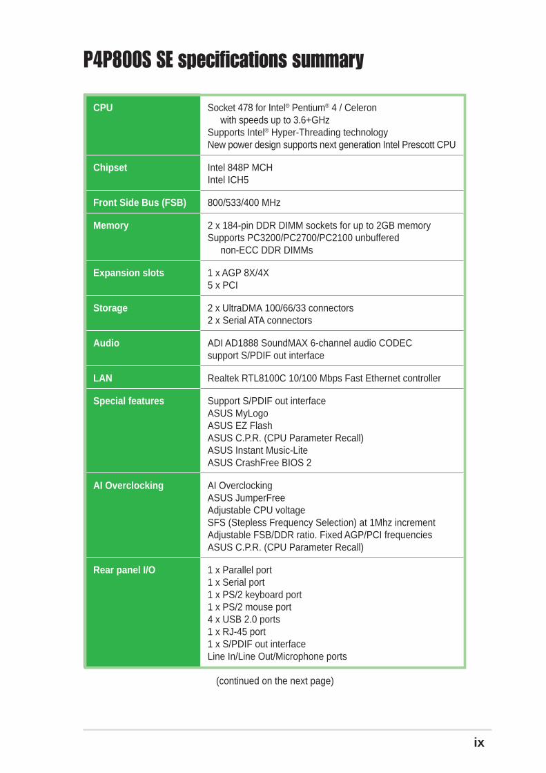
P4P800S SE specifications summary
(continued on the next page)
CPU
Chipset
Front Side Bus (FSB)
Memory
Expansion slots
Storage
Audio
LAN
Special features
AI Overclocking
Rear panel I/O
Socket 478 for Intel® Pentium® 4 / Celeron with speeds up to 3.6+GHzSupports Intel® Hyper-Threading technologyNew power design supports next generation Intel Prescott CPU
Intel 848P MCHIntel ICH5
800/533/400 MHz
2 x 184-pin DDR DIMM sockets for up to 2GB memorySupports PC3200/PC2700/PC2100 unbuffered non-ECC DDR DIMMs
1 x AGP 8X/4X5 x PCI
2 x UltraDMA 100/66/33 connectors2 x Serial ATA connectors
ADI AD1888 SoundMAX 6-channel audio CODECsupport S/PDIF out interface
Realtek RTL8100C 10/100 Mbps Fast Ethernet controller
Support S/PDIF out interfaceASUS MyLogoASUS EZ FlashASUS C.P.R. (CPU Parameter Recall)ASUS Instant Music-LiteASUS CrashFree BIOS 2
AI OverclockingASUS JumperFreeAdjustable CPU voltageSFS (Stepless Frequency Selection) at 1Mhz incrementAdjustable FSB/DDR ratio. Fixed AGP/PCI frequenciesASUS C.P.R. (CPU Parameter Recall)
1 x Parallel port1 x Serial port1 x PS/2 keyboard port1 x PS/2 mouse port4 x USB 2.0 ports1 x RJ-45 port1 x S/PDIF out interfaceLine In/Line Out/Microphone ports

x
P4P800S SE specifications summary
* Specifications are subject to change without notice.
Internal I/O
BIOS features
Industry standard
Manageability
Power Requirement
Form Factor
Support CD contents
2 x USB 2.0 connector for 4 additional USB portsCPU/Chassis fan connectors20-pin/4-pin ATX 12V power connectorsCD/AUX/MODEM connectorsGame/MIDI port connector20-pin panel connectorFront panel audio connector
3Mb Flash ROM, AMI BIOS, ACPI, PnP, DMI2.0, WfM 2.0,SM BIOS 2.3, DMI 2.0, ASUS CrashFree BIOS 2, ASUS EZFlash, ASUS MyLogo
PCI 2.3, USB 2.0/1.1
DMI 2.0, WOL/WOR by PME, SMBus
ATX power supply (with 4-pin 12V plug)
ATX form factor: 12 in x 8.2 in (30.5 cm x 20.8 cm)
Device driversASUS PC ProbeASUS LiveUpdateTrend Micro™ PC-cillin 2002 anti-virus software

Chapter 1
This chapter describes the features of themotherboard. It includes brief descriptions of themotherboard components, and illustrations of thelayout, jumper settings, and connectors.
Product introduction

1-2 Chapter 1: Product introduction
1.1 Welcome!Thank you for buying the ASUS® P4P800S SE motherboard!
The motherboard delivers a host of new features and latest technologies making itanother standout in the long line of ASUS quality motherboards!
The motherboard incorporates the Intel® Pentium® 4 / Celeron Processor in478-pin package coupled with the Intel® 848P MCH chipset to set a newbenchmark for an effective desktop platform solution.
Supporting up to 2GB of system memory with PC3200/2700/2100 DDR SDRAM,high-resolution graphics via an AGP 8X slot, Serial ATA support, USB 2.0, and 6-channel audio features, the P4P800S SE is your affordable vehicle to enter theworld of computing!
Before you start installing the motherboard, and hardware devices on it, check theitems in your package with the list below.
1.2 Package contentsCheck your P4P800S SE package for the following items.
If any of the above items is damaged or missing, contact your retailer.
1.3 Special featuresLatest processor technology
The motherboard supports the Intel® Pentium® 4 processor with 512KB L2 cache andan 800/533/400 MHz system bus. The CPU features the Intel Hyper-ThreadingTechnology and a new power design that allows up to 3.6GHz core frequencies.The motherboard will also support the next generation Intel Prescott CPU whenavailable. See page 1-10.
ASUS P4P800S SE motherboard
ASUS motherboard support CD
1 x UltraDMA 100/66 cable
1 x Floppy disk cable
I/O shield
Bag of extra jumper caps
User Guide
ASUS P4P800S SE motherboard user guide 1-3
DDR400 (PC3200) support
DDR400 (PC3200), the latest and fastest DDR memory standard, supportsbandwidth of up to 3.2 GB/s to provide enhanced system performance. See 1-12.
Serial ATA technology
The motherboard bundles the new Serial ATA technology through the SATAinterfaces onboard. The SATA specification allows for thinner, more flexible cableswith lower pin count, reduced voltage requirement, up to 150 MB/s data transferrate, and software compatibility with the legacy Parallel ATA. See page 1-20.
AGP 8X support
AGP8X is the next generation VGA interface specification that enables enhancedgraphics performance with high bandwidth up to 2.12GB/s. See page 1-16.
USB 2.0 technology
The motherboard implements the new Universal Serial Bus (USB) 2.0specification, extending the connection speed from 12 Mbps on USB 1.1 to a fast480 Mbps on USB 2.0. See pages 1-6 and 1-24.
10/100 Mbps LAN support
Easy connectivity to your network or broadband connection with the onboard LANport. See pages 1-6.
6-channel digital audio
The ADI AD1888 AC’97 audio CODEC onboard provides 6-channel audio playbackfor 5.1 surround sound using digital audio devices via a Sony/Philips DigitalInterface (S/PDIF) jack located at the rear panel I/O. See pages 1-5, 1-6, 3-3.
AI Overclocking
This feature allows convenient overclocking up to 30% (depending on the installedCPU and DRAM) to enhance system performance while still maintaining systemstability. See page 2-16 to set the BIOS items for overclocking.
CrashFree BIOS 2
CrashFree BIOS 2 allows users to restore BIOS data from a floppy diskette orrecovery CD when BIOS code and data are corrupted during upgrade or wheninvaded by a virus. ASUS motherboards now enable users to enjoy this protectionfeature without the need to pay for an optional ROM. See page 2-6.
ASUS Instant Music Lite
This unique feature allows you to playback audio files even before entering theoperating system. Just press the ASUS Instant Music Lite special function keysand enjoy the music! See pages 2-25, 3-5.

1-4 Chapter 1: Product introduction
1.4 Motherboard componentsBefore you install the motherboard, learn about its major components andavailable features to facilitate the installation and future upgrades. Refer to thesucceeding pages for the component descriptions.
643 5
8
2
12
16
1514
13
1 7
1011 9
17
27 24
20
21
22
23
18 19
2526

ASUS P4P800S SE motherboard user guide 1-5
ATX power connector. This 20-pin connector connects to an ATX powersupply. The power supply must have at least 2A on the +5VSB lead and 15Aon the +12V lead.
ATX 12V connector. This power connector connects the 4-pin 12V plug fromthe ATX 12V power supply.
CPU socket. A 478-pin surface mount, Zero Insertion Force (ZIF) socket forthe Intel® Pentium® 4 Processor, with 800/533/400 MHz system bus that allows6.4GB/s, 4.3GB/s, and 3.2GB/s data transfer rates, respectively.
North bridge controller. The Intel® 848P Memory Controller Hub providesthe processor interface with 800/533/400 MHz frequency, system memoryinterface at 400/333/266MHz operation, and 1.5V AGP interface that supportsAGP 3.0 specification including 8X Fast Write protocol. The Intel® 848PMemory Controller Hub interconnects to the SouthBridge ICH5 via the Intel®
proprietary Hub Interface.
Super I/O controller. This Winbond Low Pin Count (LPC) interface providesthe commonly used Super I/O functionality. The chipset supports a high-performance floppy disk controller for a 360K/720K/1.44M/2.88M floppy diskdrive, a multi-mode parallel port, two standard compatible UARTs, and a FlashROM interface.
DDR DIMM sockets. These two 184-pin DIMM sockets support up to 2GBsystem memory using unbuffered non-ECC PC3200/2700/2100 DDR DIMMs.
Floppy disk connector. This connector accommodates the provided ribboncable for the floppy disk drive. One side of the connector is slotted to preventincorrect insertion of the floppy disk cable.
IDE connectors. These dual-channel bus master IDE connectors supportUltra DMA100/66, PIO Modes 3 & 4 IDE devices. Both the primary (blue) andsecondary (black) connectors are slotted to prevent incorrect insertion of theIDE ribbon cable.
SATA connectors. These connectors support Serial ATA HDDs and allowup to 150MB/s data transfer rate using thin 4-conductor SATA cables.
Flash ROM. This 3Mb firmware contains the programmable BIOS program.
South bridge controller. The fifth-generation Intel I/O Controller Hub (ICH5)is a subsystem that integrates various I/O functions including 2-channelATA100 bus master IDE controller, SATA controller, up to eight USB 2.0/1.1ports, I/O APIC, SMBus controller, LPC interface, AC’97 2.3 interface, and PCI2.3 interface. The ICH5 also contains the necessary arbitration and bufferingfor efficient utilization of these interfaces.
Standby power LED. This LED lights up if there is a standby power on themotherboard. This LED acts as a reminder to turn off the system powerbefore plugging or unplugging devices.
Audio CODEC. The ADI AD1888 is an AC’97 CODEC that allows6-channel audio playback.
11
12
10
9
8
7
6
5
4
3
2
1
13

1-6 Chapter 1: Product introduction
USB 2.0 ports 3 and 4. These two 4-pin Universal Serial Bus (USB) portsare available for connecting USB 2.0 devices.
USB 2.0 ports 1 and 2. These two 4-pin Universal Serial Bus (USB) portsare available for connecting USB 2.0 devices.
Serial port. This 9-pin COM1 port is for pointing devices or other serialdevices.
S/PDIF out jack. This jack connects to external audio output devices.
PS/2 keyboard port. This purple connector is for a PS/2 keyboard.
LAN controller. This Realtek RTL8100C 10/100 LAN controller supports10BASE-T/100BASE-TX networking.
PCI slots. These 32-bit PCI 2.3 expansion slots support bus master PCIcards like SCSI or LAN cards with 133MB/s maximum throughput.
AGP 8X slot. This Accelerated Graphics Port (AGP) slot supports 1.5V AGP8X/4X mode graphics cards for 3D graphical applications.
PS/2 mouse port. This green 6-pin connector is for a PS/2 mouse.
Parallel port. This 25-pin port connects a parallel printer, a scanner, or otherdevices.
RJ-45 port. This port allows connection to a Local Area Network (LAN)through a network hub.
Line In jack. This Line In (light blue) jack connects a tape player or otheraudio sources. In 6-channel mode, the function of this jack becomes Bass/Center.
Line Out jack. This Line Out (lime) jack connects a headphone or aspeaker. In 6-channel mode, the function of this jack becomes FrontSpeaker Out.
Microphone jack. This Mic (pink) jack connects a microphone. In 6-channelmode, the function of this jack becomes Rear Speaker Out.
15
16
17
18
19
20
22
21
23
24
25
Audio 2, 4 or 6-channel configuration
Headphone/2-Speaker 4-Speaker 6-Speaker
Light Blue Line In Line In Bass/Center Lime Line Out Front Speaker Out Front Speaker Out Pink Mic In Rear Speaker Out Rear Speaker Out
The functions of the Line Out, Line In, and Microphone jacks change when youselect the 6-channel audio configuration as shown in the following table:
26
14
27

ASUS P4P800S SE motherboard user guide 1-7
1.5 Motherboard layout
PCI1
PANEL1
P4P800S SE
®
CD1
AUX1
SuperI/O
3MbFWH
Accelerated Graphics Port (AGP)
CPU_FAN1
FP_AUDIO1
AudioCodec
GAME1
CLRTC1 PRI_IDE1
SE
C_I
DE
1
ATX
Pow
er C
onne
ctor DD
R D
IMM
1 (6
4 bi
t,184
-pin
mod
ule)
CHA_FAN1
IntelICH5
USB56
SB_PWR1
USBPW78
20.8cm( 8.2in)
30.5
cm (
12.0
in)
DD
R D
IMM
2 (6
4 bi
t,184
-pin
mod
ule)
RJ-45Top:
USB3USB4
Bottom:
USB12
PS/2KBMST: MouseB: Keyboard
SPDIF1
PA
RA
LLE
L P
OR
T
COM1
PCI2
PCI3
PCI4
PCI5
Intel848PMemory
ControllerHub
ATX12V1
CR2032 3VLithium Cell
CMOS Power
Socket 478
USB78
Below:Mic InCenter:Line OutTop:Line In
SATA1
SATA2
USBPW56
MODEM1
RT
L810
0C
FLO
PP
Y1
USBPW12USBPW34
KBPWR1
CHASSIS1

1-8 Chapter 1: Product introduction
1.6 Before you proceedTake note of the following precautions before you install motherboard componentsor change any motherboard settings.
1. Unplug the power cord from the wall socket before touching anycomponent.
2. Use a grounded wrist strap or touch a safely grounded object or to a metalobject, such as the power supply case, before handling components toavoid damaging them due to static electricity.
3. Hold components by the edges to avoid touching the ICs on them.
4. Whenever you uninstall any component, place it on a grounded antistaticpad or in the bag that came with the component.
5. Before you install or remove any component, ensure that the ATXpower supply is switched off or the power cord is detached from thepower supply. Failure to do so may cause severe damage to themotherboard, peripherals, and/or components.
P4P800S SE
®
P4P800S SE Onboard LED
SB_PWR1
ONStandbyPower
OFFPowered
Off
ASUS P4P800S SE motherboard user guide 1-9
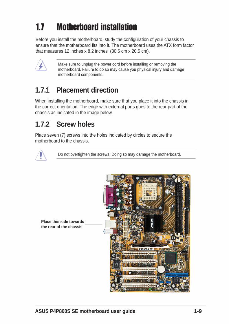
1.7 Motherboard installationBefore you install the motherboard, study the configuration of your chassis toensure that the motherboard fits into it. The motherboard uses the ATX form factorthat measures 12 inches x 8.2 inches (30.5 cm x 20.5 cm).
Do not overtighten the screws! Doing so may damage the motherboard.
1.7.1 Placement directionWhen installing the motherboard, make sure that you place it into the chassis inthe correct orientation. The edge with external ports goes to the rear part of thechassis as indicated in the image below.
1.7.2 Screw holesPlace seven (7) screws into the holes indicated by circles to secure themotherboard to the chassis.
Make sure to unplug the power cord before installing or removing themotherboard. Failure to do so may cause you physical injury and damagemotherboard components.
Place this side towardsthe rear of the chassis

1-10 Chapter 1: Product introduction
1.8 Central Processing Unit (CPU)
1.8.1 OverviewThe motherboard comes with a surface mount 478-pin Zero Insertion Force (ZIF)socket. The socket is designed for the Intel® Pentium® 4 Processor in the 478-pinpackage with 512KB L2 cache. This processor supports 800/533/400MHz frontside bus (FSB), and allows data transfer rates of up to 6.4GB/s. The socket willalso support the Intel Prescott CPU when available.
Note in the illustration that the CPU has agold triangular mark on one corner. Thismark indicates the processor Pin 1 thatshould match a specific corner of theCPU socket.
Incorrect installation of the CPU into the socket may bend the pins andseverely damage the CPU!
Gold Mark
Notes on Intel® Hyper-Threading Technology
To use the Hyper-Threading Technology on this motherboard:
1. Buy an Intel Pentium 4 CPU that supports Hyper-Threading Technology. Installthe CPU.
2. Power up the system and enter BIOS Setup (see Chapter 2). Under theAdvanced Menu, make sure that the item Hyper-Threading Technology is setto Enabled. The item appears only if you installed a CPU that supports Hyper-Threading Technology.
3. Reboot the computer.
1. This motherboard supports Intel® Pentium 4 CPUs with Hyper-ThreadingTechnology.
2. Make sure to enable the Hyper-Threading Technology item in the BIOSbefore installing a supported operating system. See section “2.4.2 CPUConfiguration” for details.
3. To verify the Hyper-Threading feature, go to the Windows OS SystemProperties -> Hardware -> Device Manager -> Processors. The listshould display two existing processors.
4. Hyper-Threading Technology is supported under Windows® XP™ and laterversions only.
5. It is recommended that you install Windows® XP™ Service Pack 1.6. For more information on Hyper-Threading Technology, visit
www.intel.com/info/hyperthreading.
ASUS P4P800S SE motherboard user guide 1-11
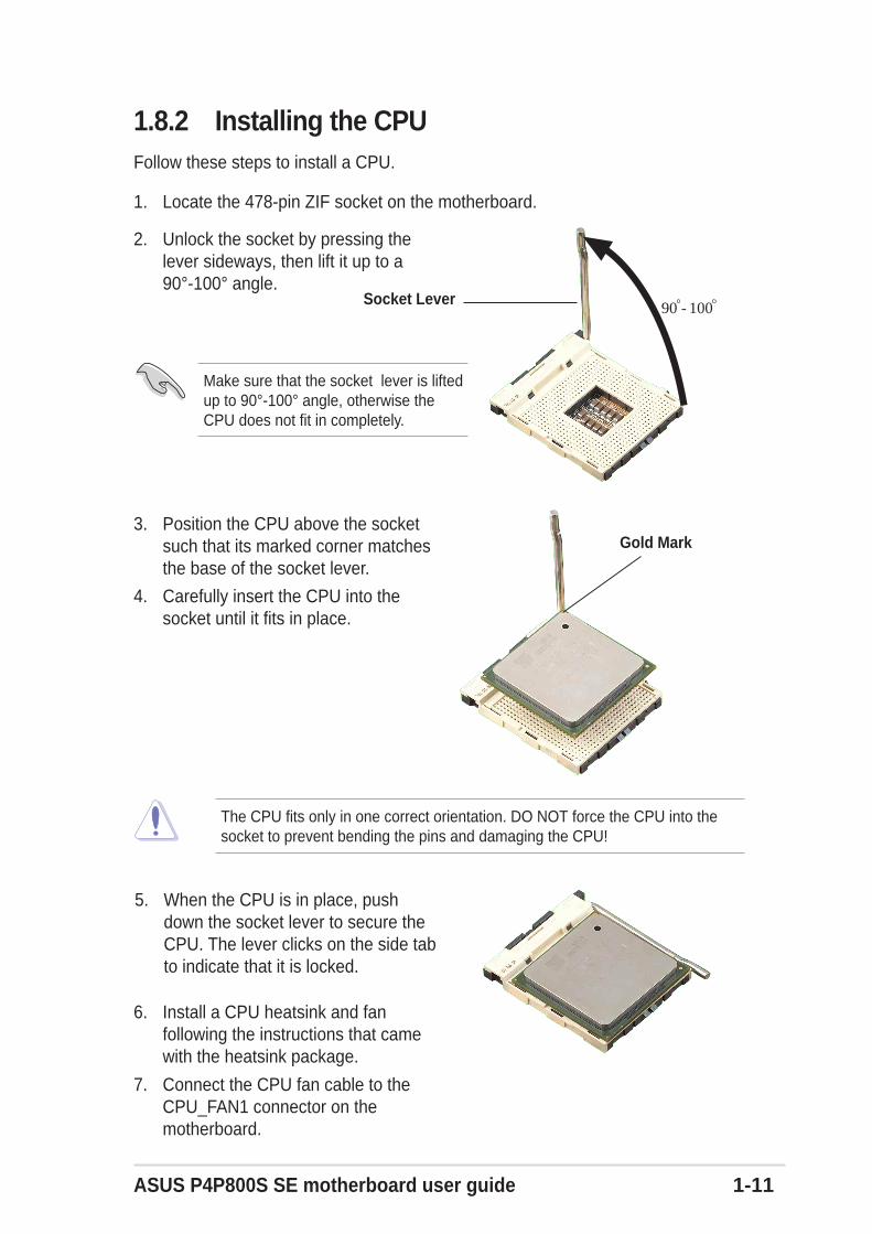
1.8.2 Installing the CPUFollow these steps to install a CPU.
1. Locate the 478-pin ZIF socket on the motherboard.
2. Unlock the socket by pressing thelever sideways, then lift it up to a90°-100° angle.
3. Position the CPU above the socketsuch that its marked corner matchesthe base of the socket lever.
4. Carefully insert the CPU into thesocket until it fits in place.
The CPU fits only in one correct orientation. DO NOT force the CPU into thesocket to prevent bending the pins and damaging the CPU!
5. When the CPU is in place, pushdown the socket lever to secure theCPU. The lever clicks on the side tabto indicate that it is locked.
Socket Lever90 - 100
Gold Mark
6. Install a CPU heatsink and fanfollowing the instructions that camewith the heatsink package.
7. Connect the CPU fan cable to theCPU_FAN1 connector on themotherboard.
Make sure that the socket lever is liftedup to 90°-100° angle, otherwise theCPU does not fit in completely.
1-12 Chapter 1: Product introduction
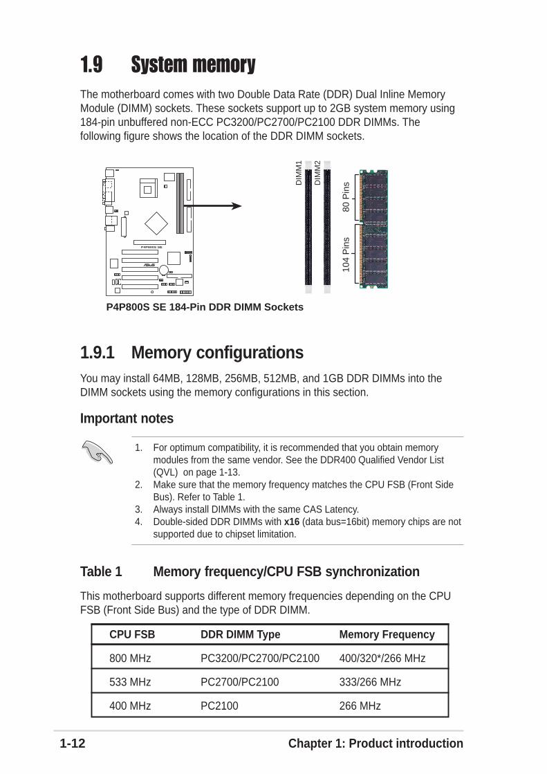
1.9 System memoryThe motherboard comes with two Double Data Rate (DDR) Dual Inline MemoryModule (DIMM) sockets. These sockets support up to 2GB system memory using184-pin unbuffered non-ECC PC3200/PC2700/PC2100 DDR DIMMs. Thefollowing figure shows the location of the DDR DIMM sockets.
1.9.1 Memory configurationsYou may install 64MB, 128MB, 256MB, 512MB, and 1GB DDR DIMMs into theDIMM sockets using the memory configurations in this section.
Important notes
1. For optimum compatibility, it is recommended that you obtain memorymodules from the same vendor. See the DDR400 Qualified Vendor List(QVL) on page 1-13.
2. Make sure that the memory frequency matches the CPU FSB (Front SideBus). Refer to Table 1.
3. Always install DIMMs with the same CAS Latency.4. Double-sided DDR DIMMs with x16 (data bus=16bit) memory chips are not
supported due to chipset limitation.
P4P800S SE
®
P4P800S SE 184-Pin DDR DIMM Sockets
80 P
ins
104
Pin
s
DIM
M1
DIM
M2
This motherboard supports different memory frequencies depending on the CPUFSB (Front Side Bus) and the type of DDR DIMM.
CPU FSB DDR DIMM Type Memory Frequency
800 MHz PC3200/PC2700/PC2100 400/320*/266 MHz
533 MHz PC2700/PC2100 333/266 MHz
400 MHz PC2100 266 MHz
Table 1 Memory frequency/CPU FSB synchronization
ASUS P4P800S SE motherboard user guide 1-13
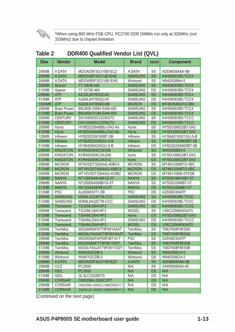
Table 2 DDR400 Qualified Vendor List (QVL) Size Vendor Model Brand DS/SS Component
256MB A DATA MDOAD5F3G315B1EC2 A DATA SS ADD8608A8A-5B256MB A DATA MDOSS6F3G31JB1EAE SAMSUNG SS K4H560838D-TCC4256MB A DATA MDOWB5F3G316B1EAE Winbond SS W942508BH-5256MB Apacer 77.10636.465 SAMSUNG SS K4H560838D-TCC4512MB Apacer 77.10736.464 SAMSUNG DS K4H560838D-TCC4256MB ATP AG32L64T8SQC4S SAMSUNG SS K4H560838D-TCC4512MB ATP AG64L64T8SQC4S SAMSUNG DS K4H560838D-TCC41024MB ATP AG28L64T8SMC4M MICRON DS MT46V64M4TG-5BC256MB Brain Power B6U808-256M-SAM-400 SAMSUNG SS K4H560838D-TCC4512MB Brain Power B6U808-512M-SAM-400 SAMSUNG DS K4H560838D-TCC4256MB CENTURY DXV6S8SSCCD3K27C SAMSUNG SS K4H560838D-TCCC512MB CENTURY DXV2S8SSCCD3K27C SAMSUNG DS K4H560838D-TCCC256MB Hynix HYMD232646B8J-D43 AA Hynix SS HY5DU56822BT-D43512MB Hynix HYMD264646B8J-D43 AA Hynix DS HY5DU56822BT-D43128MB Infineon HYB25D256160BT-5B Infineon SS HYS64D16301GU-5-B256MB Infineon HYS64D32300GU-5-B Infineon SS HYB25D256800BT-5B512MB Infineon HYS64D64320GU-5-B Infineon DS HYB25D256800BT-5B256MB KINGSTON KVR400X64C25/256 Winbond SS W942508BH-5256MB KINGSTON KVR400X64C3A/256 hynix SS HY5DU56822BT-D43512MB KINGSTON KVR400X64C3A/512 hynix DS HY5DU56822BT-D43256MB MICRON MT8VDDT3264AG-40BC4 MICRON SS MT46V32M8TG-5BC512MB MICRON MT16VDDT6464AG-40BC4 MICRON DS MT46V32M8TG-5BC256MB MICRON MT16VDDT3264AG-403B2 MICRON DS MT46V16M8-5TESB128MB NANYA NT128D64SH4B1G-5T NANYA SS NT5DS16M16BT-5T256MB NANYA NT256D64S88B1G-5T NANYA SS NT5DS32M8BT-5T512MB NANYA N512D64S8HB1G-5T NANYA DS NT5DS32M8BT-5T512MB PSC AL6D8A53T1-5B PSC DS A2S56D30ATP256MB SAMSUNG M368L3223ETM-CCC SAMSUNG SS K4H560838E-TCCC512MB SAMSUNG M368L6432ETM-CCC SAMSUNG DS K4H560838E-TCCC256MB Transcend TS32MLD64V4F3 SAMSUNG SS K4H560838D-TCCC256MB Transcend TS32MLD64V4F3 MOSEL SS V58C2256804SAT5512MB Transcend TS64MLD64V4F3 Hynix DS HY5DU56822BT-D43512MB Transcend TS64MLD64V4F3 SAMSUNG DS K4H560838D-TCCC512MB Transcend TS64MLD64V4F3 MOSEL DS V58C2256804SAT5256MB TwinMos M2G9I08AFATT9F081AA4T TwinMos SS TMD7608F8E50D512MB TwinMos M2G9J16AGATT9F081AA4T TwinMos DS TMD7608F8E50D256MB TwinMos M2S9I08AFAPS9F0811A-T PSC SS A2S56D30ATP256MB TwinMos M2G9I08AFTT9F0811DDT TwinMos SS TMD7608F8E50B512MB TwinMos M2G9J16AJATT9F0811DDT TwinMos DS TMD7608F8E50B256MB Winbond W9425GCDB-5 Winbond SS W942508CH-5512MB Winbond W9451GCDB-5 Winbond DS W942508CH-5256MB A DATA MDOAD5F3G31YB1EZ2 A DATA SS ADD8608A8A-5B256MB OCZ PC3500 N/A SS X4W560840A-40256MB GEIL PC3500 N/A DS N/A512MB GEIL GL3LC32G88TG N/A DS N/A256MB CORSAIR CMX256A-3500C2PT N/A DS N/A256MB CORSAIR CMX256A-3500C2 XMS3502V1.1 N/A DS N/A512MB CORSAIR CMX512A-3500C2 XMS3502V1.1 N/A DS N/A
*When using 800 MHz FSB CPU, PC2700 DDR DIMMs run only at 320MHz (not333MHz) due to chipset limitation.
(Continued on the next page)
1-14 Chapter 1: Product introduction
DDR400 Qualified Vendor List (QVL) Size Vendor Model Brand DS/SS Component
256MB KINGSTON KVR400X72C25/256 Winbond SS W942508BH-5(ECC)*512MB KINGSTON KVR400X72C25/512 Winbond DS W942508BH-5(ECC)*256MB SAMSUNG M381L3223ETM-CCC SAMSUNG SS K4H560838E-TCCC(ECC)*512MB SAMSUNG M381L6423ETM-CCC SAMSUNG DS K4H560838E-TCCC(ECC)*256MB ATP AG32L72T8SQC4S SAMSUNG SS K4H560838D-TCC4(ECC)*512MB ATP AG64L72T8SQC4S SAMSUNG DS K4H560838D-TCC4(ECC)*256MB KINGSTON KVR400X72C3A/256 MOSEL SS V58C2256804SAT5(ECC)*512MB KINGSTON KVR400X72C3A/512 MOSEL DS V58C2256804SAT5(ECC)*256MB KINGMAX MPXB62D-38KT3R KINGMAX SS KDL388P4EA-50512MB KINGMAX MPXC22D-38KT3R KINGMAX DS KDL388P4EA-50(A)
Make sure to unplug the power supply before adding or removing DIMMs orother system components. Failure to do so may cause severe damage to boththe motherboard and the components.
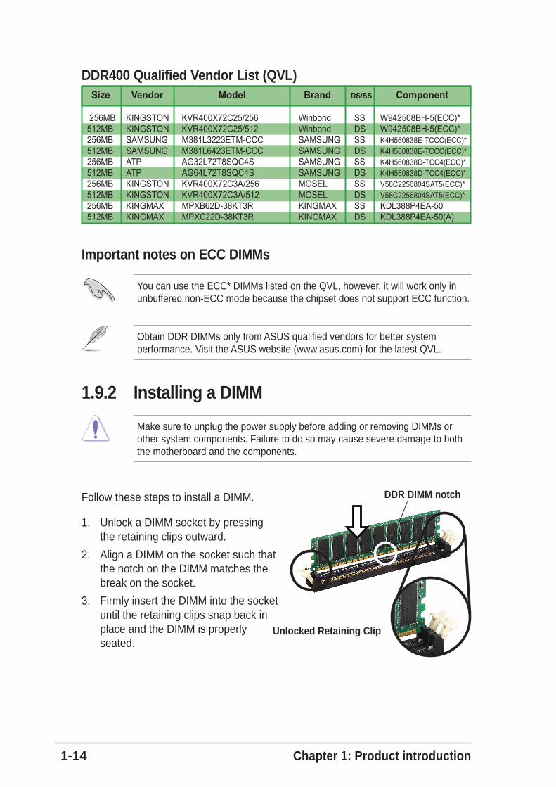
Follow these steps to install a DIMM.
1. Unlock a DIMM socket by pressingthe retaining clips outward.
2. Align a DIMM on the socket such thatthe notch on the DIMM matches thebreak on the socket.
3. Firmly insert the DIMM into the socketuntil the retaining clips snap back inplace and the DIMM is properlyseated.
Unlocked Retaining Clip
DDR DIMM notch
1.9.2 Installing a DIMM
Obtain DDR DIMMs only from ASUS qualified vendors for better systemperformance. Visit the ASUS website (www.asus.com) for the latest QVL.
You can use the ECC* DIMMs listed on the QVL, however, it will work only inunbuffered non-ECC mode because the chipset does not support ECC function.
Important notes on ECC DIMMs
ASUS P4P800S SE motherboard user guide 1-15
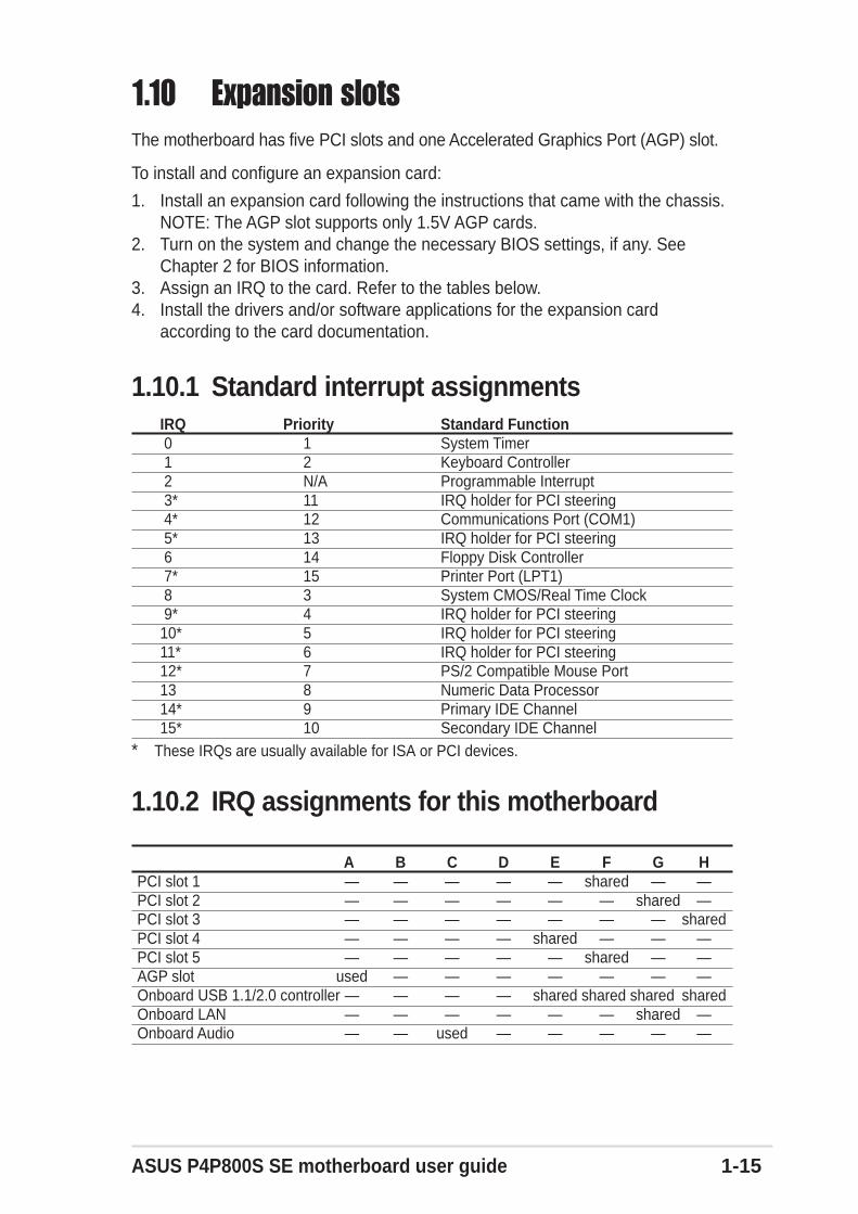
1.10.1 Standard interrupt assignmentsIRQ Priority Standard Function 0 1 System Timer 1 2 Keyboard Controller 2 N/A Programmable Interrupt 3* 11 IRQ holder for PCI steering 4* 12 Communications Port (COM1) 5* 13 IRQ holder for PCI steering 6 14 Floppy Disk Controller 7* 15 Printer Port (LPT1) 8 3 System CMOS/Real Time Clock 9* 4 IRQ holder for PCI steering10* 5 IRQ holder for PCI steering11* 6 IRQ holder for PCI steering12* 7 PS/2 Compatible Mouse Port13 8 Numeric Data Processor14* 9 Primary IDE Channel15* 10 Secondary IDE Channel
* These IRQs are usually available for ISA or PCI devices.
1.10.2 IRQ assignments for this motherboard
A B C D E F G HPCI slot 1 — — — — — shared — —PCI slot 2 — — — — — — shared —PCI slot 3 — — — — — — — sharedPCI slot 4 — — — — shared — — —PCI slot 5 — — — — — shared — —AGP slot used — — — — — — —Onboard USB 1.1/2.0 controller — — — — shared shared shared sharedOnboard LAN — — — — — — shared —Onboard Audio — — used — — — — —
1.10 Expansion slotsThe motherboard has five PCI slots and one Accelerated Graphics Port (AGP) slot.
To install and configure an expansion card:
1. Install an expansion card following the instructions that came with the chassis.NOTE: The AGP slot supports only 1.5V AGP cards.
2. Turn on the system and change the necessary BIOS settings, if any. SeeChapter 2 for BIOS information.
3. Assign an IRQ to the card. Refer to the tables below.4. Install the drivers and/or software applications for the expansion card
according to the card documentation.

1-16 Chapter 1: Product introduction
1.10.3 PCI slotsThere are five 32-bit PCI slots on this motherboard. The slots support PCI cardssuch as a LAN card, SCSI card, USB card, and other cards that comply with PCIspecifications.
1.10.4 AGP slotThis motherboard has an Accelerated Graphics Port (AGP) slot that supports AGP8X/4X (+1.5V) cards. When you buy an AGP card, make sure that you ask for onewith +1.5V specification.
Note the notches on the card golden fingers to ensure that they fit the AGP slot onyour motherboard.
If installing the ATi 9500 or 9700 Pro Series VGA cards, use only the cardversion PN xxx-xxxxx-30 or later, for optimum performance and overclockingstability.
P4P800S SE
®
P4P800S SE Accelerated Graphics Port (AGP)
Keyed for 1.5v
Install only +1.5V AGP cards. This motherboard does not support 3.3V AGPcards.
• When installing long PCI cards, it is recommended that to install in PCIslot 3.
• Long PCI cards installed in PCI slot 1 or 2 may interfere with the SATAconnectors.
• PCI 64-bit cards installed in PCI slot 5 may interfere with the USBconnectors and PCI 64-bit cards installed in PCI slot 4 may interfere withthe RAID connector.

ASUS P4P800S SE motherboard user guide 1-17
1.11 Jumpers1. Clear RTC RAM (CLRTC1)
This jumper allows you to clear the Real Time Clock (RTC) RAM in CMOS.You can clear the CMOS memory of date, time, and system setup parametersby erasing the CMOS RTC RAM data. The RAM data in CMOS, that includesystem setup information such as system passwords, is powered by theonboard button cell battery.
To erase the RTC RAM:
1. Turn OFF the computer and unplug the power cord.2. Move the jumper cap from pins 2-3 (default) to pins 1-2. Keep the cap on
pins 1-2 for about 5~10 seconds, then move the cap back to pins 2-3.3. Plug the power cord and turn ON the computer.4. Hold down the <Del> key during the boot process and enter BIOS setup
to re-enter data.
P4P800S SE
®
P4P800S SE Clear RTC RAM
CLRTC1
Normal Clear CMOS(Default)
1 2 2 3
Except when clearing the RTC RAM, never remove the cap on CLRTC1 jumperdefault position. Removing the cap will cause system boot failure!
You do not need to clear the RTC when the system hangs due to overclocking.For system failure due to overclocking, use the C.P.R. (CPU Parameter Recall)feature. Shut down and reboot the system so BIOS can automatically resetparameter settings to default values.

1-18 Chapter 1: Product introduction
P4P800S SE
®
P4P800S SE Keyboard Power Setting
(Default)+5V +5VSB
KBPWR1
2 31 2
P4P800S SE
®
P4P800S SE USB Device Wake Up
3221
+5V(Default)
+5VSB
USBPW78USBPW56
3221
+5V(Default)
+5VSB
USBPW12USBPW34
2. USB device wake-up (3-pin USBPW12, USBPW34, USBPW56, USBPW78)
Set these jumpers to +5V to wake up the computer from S1 sleep mode (CPUstopped, DRAM refreshed, system running in low power mode) using theconnected USB devices. Set to +5VSB to wake up from S3 sleep mode (nopower to CPU, DRAM in slow refresh, power supply in reduced power mode).All jumpers are set to pins 1-2 (+5V) by default because not all computers havethe appropriate power supply to support this feature.
The USBPW12 and USBPW34 jumpers are for the rear USB ports. TheUSBPW56 and USBPW78 jumpers are for the internal USB header that youcan connect to the front USB ports.
3. Keyboard power (3-pin KBPWR1)
This jumper allows you to enable or disable the keyboard wake-up feature. Setthis jumper to pins 2-3 (+5VSB) if you wish to wake up the computer when youpress a key on the keyboard (the default value is [Disabled]). This featurerequires an ATX power supply that can supply at least 1A on the +5VSB lead,and a corresponding setting in the BIOS (see section 2.5.1 Power Up Control).
1. This feature requires a power supply that can provide at least 2A on the+5VSB lead when these jumpers are set to +5VSB. Otherwise, the systemdoes not power up.
2. The total current consumed must NOT exceed the power supplycapability (+5VSB) whether under normal or in sleep mode.
ASUS P4P800S SE motherboard user guide 1-19
1.12 ConnectorsThis section describes and illustrates the internal connectors on the motherboard.
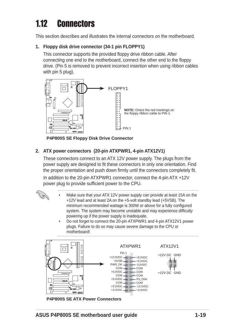
1. Floppy disk drive connector (34-1 pin FLOPPY1)
This connector supports the provided floppy drive ribbon cable. Afterconnecting one end to the motherboard, connect the other end to the floppydrive. (Pin 5 is removed to prevent incorrect insertion when using ribbon cableswith pin 5 plug).
P4P800S SE
®
NOTE: Orient the red markings onthe floppy ribbon cable to PIN 1.
P4P800S SE Floppy Disk Drive Connector
FLOPPY1
PIN 1
2. ATX power connectors (20-pin ATXPWR1, 4-pin ATX12V1)
These connectors connect to an ATX 12V power supply. The plugs from thepower supply are designed to fit these connectors in only one orientation. Findthe proper orientation and push down firmly until the connectors completely fit.
In addition to the 20-pin ATXPWR1 connector, connect the 4-pin ATX +12Vpower plug to provide sufficient power to the CPU.
• Make sure that your ATX 12V power supply can provide at least 15A on the+12V lead and at least 2A on the +5-volt standby lead (+5VSB). Theminimum recommended wattage is 300W or above for a fully configuredsystem. The system may become unstable and may experience difficultypowering up if the power supply is inadequate.
• Do not forget to connect the 20-pin ATXPWR1 and 4-pin ATX12V1 powerplugs. Failure to do so may cause severe damage to the CPU ormotherboard!
P4P800S SE
®
P4P800S SE ATX Power Connectors
ATXPWR1
Pin 1
+3.3VDC-12.0VDCCOMPS_ON#
COMCOM
COM-5.0VDC+5.0VDC+5.0VDC
PWR_OK
+12.0VDC
+3.3VDC+3.3VDC
COM
+5.0VDCCOM
+5.0VDC
COM
+5VSB
ATX12V1
+12V DC GND
+12V DC GND

1-20 Chapter 1: Product introduction
3. Serial ATA connectors (7-pin SATA2, SATA1)These next generation connectors support the thin Serial ATA cables for Serial ATAhard disks. The current Serial ATA interface allows up to 150 MB/s data transferrate, faster than the standard parallel ATA with 133 MB/s (Ultra ATA/133).
P4P800S SE
®
P4P800S SE SATA Connectors
SATA1
GNDRSATA_TXP1RSATA_TXN1GNDRSATA_RXN1RSATA_RXP1GND
SATA2
GN
DR
SAT
A_T
XP
2R
SAT
A_T
XN
2G
ND
RS
ATA
_RX
N2
RS
ATA
_RX
P2
GN
D
Important notes on Serial ATA solution:
• In legacy operating system (Win 98, WinME, WinNT, DOS)environment, using SATA will disable one of the IDE channels fromICH5 south bridge chipset. See BIOS section for correct setting.
• The Serial ATA cable is smaller and more flexible allowing easierrouting inside the chassis. The lower pin count of the Serial ATAcable eliminates the problem caused by the wide, flat ribbon cablesof the Parallel ATA interface.
• Hot plug support for Serial ATA drive and connections are notavailable in this motherboard.
• Install Windows® XP™ Service Pack 1 when using Serial ATA.
The Serial ATA cable is purchased separately.

ASUS P4P800S SE motherboard user guide 1-21
Parallel ATA and Serial ATA device configurationsFollowing are the Parallel ATA and Serial ATA device configurations supported byIntel ICH5 specifications.
Native operating systems (OS) are Windows 2000/XP. ICH5 supports a maximumof six (6) devices using these OS.
Legacy OS are MS-DOS, Linux, Windows 98/Me/NT4.0. ICH5 supports amaximum of four (4) devices using these OS.
Required IDE Configuration settings in BIOS
Refer to the following table for the appropriate BIOS settings of the above P-ATAand S-ATA device configurations. See section “2.3.6 IDE Configuration” for detailson the related BIOS items.
Windows Windows 98/Me/NT4.0/LInux BIOS item 2000/XP A B C
Onboard IDE Operate Mode Enhanced Mode Compatible Mode Compatible Mode Compatible Mode
Enhanced Mode Support On S-ATA — — —IDE Port Settings — Primary P-ATA+S-ATA Sec. P-ATA+S-ATA P-ATA Ports Only
Legend: Supported — Disabled
P-ATA S-ATAOperating System Primary Secondary Port 0 Port 1
(2 devices) (2 devices) (1 device) (1 device)
1. Windows 2000/XP
2. Windows 98/Me/NT4.0, Linux, MS-DOS
Configuration A —
Configuration B —
Configuration C — —

1-22 Chapter 1: Product introduction
4. IDE connectors (40-1 pin PRI_IDE1, SEC_IDE1)
This connector supports the provided UltraDMA100/66/33 IDE ribbon cable.Connect the cable’s blue connector to the primary (recommended) or secondaryIDE connector, then connect the gray connector to the UltraDMA100/66/33 slavedevice (hard disk drive) and the black connector to the UltraDMA100/66/33 masterdevice. It is recommended that you connect non-UltraDMA100/66/33 devices tothe secondary IDE connector. If you install two hard disks, you must configure thesecond drive as a slave device by setting its jumper accordingly. Refer to the harddisk documentation for the jumper settings. BIOS supports specific device bootup.If you have more than two UltraDMA100/66/33 devices, purchase anotherUltraDMA100/66/33 cable. You may configure two hard disks to be both masterdevices with two ribbon cables – one for the primary IDE connector and anotherfor the secondary IDE connector.
1. Pin 20 on each IDE connector is removed to match the covered hole on theUltraDMA cable connector. This prevents incorrect orientation when youconnect the cables.
2. The hole near the blue connector on the UltraDMA100/66/33 cable isintentional.
3. For UltraDMA100/66 IDE devices, use the 80-conductor IDE cable.
P4P800S SE
®
P4P800S SE IDE Connectors
NOTE: Orient the red markings(usually zigzag) on the IDEribbon cable to PIN 1.
SE
C_I
DE
1
PRI_IDE1
PIN 1
PIN 1

ASUS P4P800S SE motherboard user guide 1-23
6. CPU and chassis fan connectors (3-pin CPU_FAN1, CHA_FAN1)
The fan connectors support cooling fans of 350mA~740mA (8.88W max.) or atotal of 1A~2.2A (26.64W max.) at +12V. Connect the fan cables to the fanconnectors on the motherboard, making sure that the black wire of each cablematches the ground pin of the connector.
Do not forget to connect the fan cables to the fan connectors. Lack of sufficientair flow within the system may damage the motherboard components. Theseare not jumpers! DO NOT place jumper caps on the fan connectors!
P4P800S SE
®
P4P800S SE 12-Volt Fan Connectors
CPU_FAN1
CHA_FAN1
GN
D
Rot
atio
n+
12V
GND
Rotation+12V
P4P800S SE
®
P4P800S SE Chassis Alarm Lead
CHASSIS1+
5VS
B_M
B
Cha
ssis
Sig
nal
GN
D
(Default)
5. Chassis intrusion connector (4-1 pin CHASSIS1)
This lead is for a chassis designed with intrusion detection feature. Thisrequires an external detection mechanism such as a chassis intrusion sensoror microswitch. When you remove any chassis component, the sensortriggers and sends a high-level signal to this lead to record a chassisintrusion event.
By default, the pins labeled “Chassis Signal” and “Ground” are shorted with ajumper cap. If you wish to use the chassis intrusion detection feature, removethe jumper cap from the pins.
1-24 Chapter 1: Product introduction
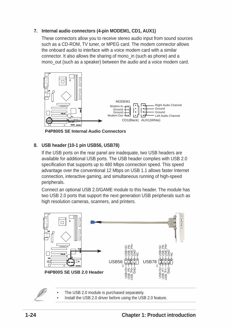
8. USB header (10-1 pin USB56, USB78)
If the USB ports on the rear panel are inadequate, two USB headers areavailable for additional USB ports. The USB header complies with USB 2.0specification that supports up to 480 Mbps connection speed. This speedadvantage over the conventional 12 Mbps on USB 1.1 allows faster Internetconnection, interactive gaming, and simultaneous running of high-speedperipherals.
Connect an optional USB 2.0/GAME module to this header. The module hastwo USB 2.0 ports that support the next generation USB peripherals such ashigh resolution cameras, scanners, and printers.
7. Internal audio connectors (4-pin MODEM1, CD1, AUX1)
These connectors allow you to receive stereo audio input from sound sourcessuch as a CD-ROM, TV tuner, or MPEG card. The modem connector allowsthe onboard audio to interface with a voice modem card with a similarconnector. It also allows the sharing of mono_in (such as phone) and amono_out (such as a speaker) between the audio and a voice modem card.
P4P800S SE
®
P4P800S SE Internal Audio Connectors
CD1(Black) AUX1(White)
Right Audio Channel
Left Audio ChannelGroundGround
MODEM1Modem-In
GroundModem-Out
Ground
P4P800S SE
®
P4P800S SE USB 2.0 Header
USB56
US
B+
5VU
SB
_P6-
US
B_P
6+G
ND
NC
US
B+
5VU
SB
_P5-
US
B_P
5+G
ND
1USB78
US
B+
5VU
SB
_P8-
US
B_P
8+G
ND
NC
US
B+
5VU
SB
_P7-
US
B_P
7+G
ND
1
• The USB 2.0 module is purchased separately.• Install the USB 2.0 driver before using the USB 2.0 feature.

ASUS P4P800S SE motherboard user guide 1-25
P4P800S SE
®
P4P800S SE Front Panel Audio Connector
FP_AUDIO1
BLI
NE
_OU
T_L
MIC
2
Line
out
_R
Line
out
_L
BLI
NE
_OU
T_R
NC
MIC
PW
R+
5VA
AG
ND
P4P800S SE
®
P4P800S SE Game Connector
GAME1
+5V
+5V
J2B
1J2
CX
MID
I_O
UT
J2C
YJ2
B2
MID
I_IN
J1B
1J1
CX
GN
DG
ND
J1C
YJ1
B2
+5V
10. GAME/MIDI connector (16-1 pin GAME1)
This connector supports a GAME/MIDI module. Connect the GAME/MIDI cablewith yellow connector to the yellow header onboard. The GAME/MIDI port onthe module connects a joystick or a game pad for playing games, and MIDIdevices for playing or editing audio files.
9. Front panel audio connector (10-1 pin FP_AUDIO1)
This is an interface for the Intel front panel audio cable that allow convenientconnection and control of audio devices.
Remove the caps from the Line out_R, BLINE_OUT_R, Line out_L andBLINE_OUT_L jumpers if you want to install an Intel front panel audio cable.
The GAME/MIDI module is purchased separately.

1-26 Chapter 1: Product introduction
11. System panel connector (20 pin PANEL1)
This connector accommodates several system front panel functions. Eachgroup of connector pins match the color of the wire connectors for easierlocation and identification.
P4P800S SE
®
P4P800S SE System Panel Connector* Requires an ATX power supply.
PLE
D-
PW
R+
5V Spe
aker
SpeakerConnectorPower LED
Gro
und
Reset SW
Gro
und
Res
etG
roun
dG
roun
d
ATX PowerSwitch*
PLE
D+
IDE
_LE
D-
IDE
_LE
D+
IDE_LED
• System Power LED Lead (3-1 pin PLED (green))
This 3-1 pin connector connects to the system power LED. The LED lights upwhen you turn on the system power, and blinks when the system is in sleepmode.
• System Warning Speaker Lead (4-pin SPKR (orange))
This 4-pin connector connects to the case-mounted speaker and allows you tohear system beeps and warnings.
• Reset Switch Lead (2-pin RESET (blue))
This 2-pin connector connects to the case-mounted reset switch for rebootingthe system without turning off the system power.
• ATX Power Switch/Soft-off Switch Lead (2-pin PWR (light green))
This connector connects a switch that controls the system power. Pressing thepower switch turns the system between ON and SLEEP, or ON and SOFTOFF, depending on the BIOS or OS settings. Pressing the power switch whilein the ON mode for more than 4 seconds turns the system OFF.
• Hard Disk Activity Lead (2-pin IDE_LED (red))
This connector supplies power to the hard disk activity LED. The read or writeactivities of any device connected to the primary or secondary IDE connectorcause this LED to light up.

Chapter 2
This chapter tells how to change system settingsthrough the BIOS Setup menus. Detaileddescriptions of the BIOS parameters are alsoprovided.
BIOS information

2-2 Chapter 2: BIOS information
2.1 Managing and updating your BIOS
2.1.1 Creating a bootable floppy disk
1. Do either one of the following to create a bootable floppy disk.
DOS environment
Insert a 1.44 MB floppy disk into the drive. At the DOS prompt, type:
format A:/S , then press the <Enter> key
Windows environment
a. From your Windows desktop, click on Start, point to Settings, then click onControl Panel.
b. Double-click on Add/Remove Programs icon from the Control Panelwindow.
c. Click on the Startup Disk tab, then on Create Disk... button.
d. Insert a 1.44 MB floppy disk when prompted. Follow the suceeding screeninstructions to complete the process.
2. Copy the original (or the latest) motherboard BIOS to the bootable floppy disk.
2.1.2 Using AFUDOS to update the BIOSUpdate the BIOS using the AFUDOS.EXE utility in DOS environment.
1. Visit the ASUS website (www.asus.com) to download the latest BIOS file foryour motherboard. Save the BIOS file to a bootable floppy disk.
2. Copy the AFUDOS.EXE utility from the support CD to the bootable floppy diskthat contains the BIOS file.
3. Boot the system from the floppy disk.
4. At the DOS prompt, type the command line:
afudos /i<filename>
where “filename” means the latest (or original) BIOS file that you copied to thebootable floppy disk.
The screen displays the status of the update process.
Write down the BIOS file name to a piece of paper. You need to type the exactBIOS file name at the prompt.
• The original BIOS file for this motherboard is in the root directoryof the support CD filenamed “P4P800SS.ROM”.
• Copy the original BIOS to a bootable floppy disk in case youneed to restore the BIOS in the future.

ASUS P4P800S SE motherboard user guide 2-3
A:\>afudos /iP4P800SS.rom
AMI Firmware Update Utility - Version 1.10
Copyright (C) 2002 American Megatrends, Inc. All rights reserved.
Reading file ..... done
Erasing flash .... done
Writing flash .... 0x0008CC00 (9%)
When the BIOS update process is complete, the utility returns to the DOSprompt.
A:\>afudos /iP4P800SS.rom
AMI Firmware Update Utility - Version 1.10
Copyright (C) 2002 American Megatrends, Inc. All rights reserved.
Reading file ..... done
Erasing flash .... done
Writing flash .... 0x0008CC00 (9%)
Verifying flash .. done
A:\>
5. Reboot the system from the hard disk.
The BIOS information on the screen is for reference only. What you see on yourscreen may not be exactly the same as shown.
DO NOT shutdown or reset the system while updating the BIOS! Doing so maycause system boot failure!
2-4 Chapter 2: BIOS information
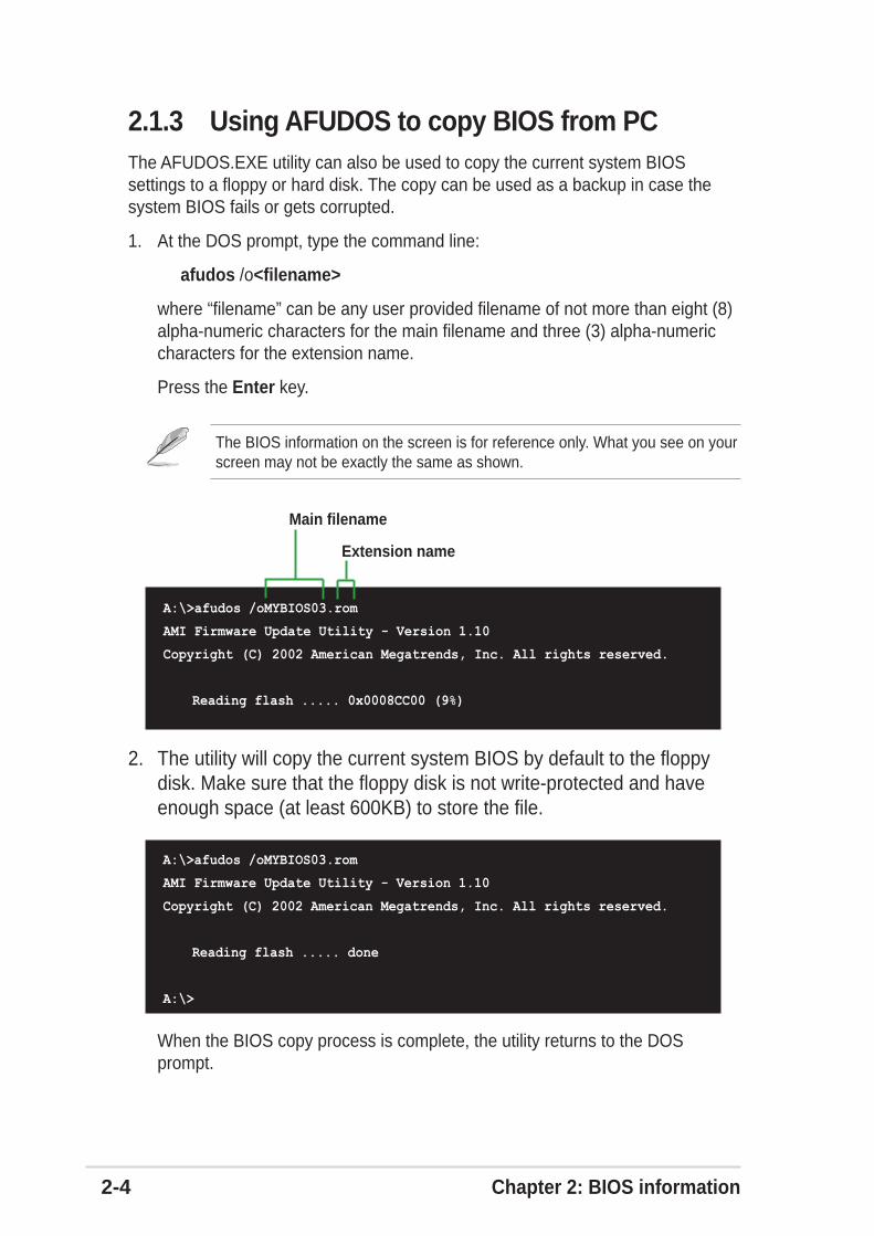
1. At the DOS prompt, type the command line:
afudos /o<filename>
where “filename” can be any user provided filename of not more than eight (8)alpha-numeric characters for the main filename and three (3) alpha-numericcharacters for the extension name.
Press the Enter key.
2. The utility will copy the current system BIOS by default to the floppydisk. Make sure that the floppy disk is not write-protected and haveenough space (at least 600KB) to store the file.
The BIOS information on the screen is for reference only. What you see on yourscreen may not be exactly the same as shown.
2.1.3 Using AFUDOS to copy BIOS from PCThe AFUDOS.EXE utility can also be used to copy the current system BIOSsettings to a floppy or hard disk. The copy can be used as a backup in case thesystem BIOS fails or gets corrupted.
When the BIOS copy process is complete, the utility returns to the DOSprompt.
Main filename
Extension name
A:\>afudos /oMYBIOS03.rom
AMI Firmware Update Utility - Version 1.10
Copyright (C) 2002 American Megatrends, Inc. All rights reserved.
Reading flash ..... 0x0008CC00 (9%)
A:\>afudos /oMYBIOS03.rom
AMI Firmware Update Utility - Version 1.10
Copyright (C) 2002 American Megatrends, Inc. All rights reserved.
Reading flash ..... done
A:\>
ASUS P4P800S SE motherboard user guide 2-5
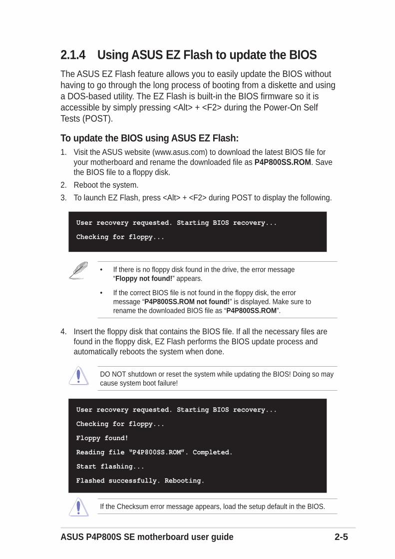
2.1.4 Using ASUS EZ Flash to update the BIOSThe ASUS EZ Flash feature allows you to easily update the BIOS withouthaving to go through the long process of booting from a diskette and usinga DOS-based utility. The EZ Flash is built-in the BIOS firmware so it isaccessible by simply pressing <Alt> + <F2> during the Power-On SelfTests (POST).
To update the BIOS using ASUS EZ Flash:1. Visit the ASUS website (www.asus.com) to download the latest BIOS file for
your motherboard and rename the downloaded file as P4P800SS.ROM. Savethe BIOS file to a floppy disk.
2. Reboot the system.
3. To launch EZ Flash, press <Alt> + <F2> during POST to display the following.
4. Insert the floppy disk that contains the BIOS file. If all the necessary files arefound in the floppy disk, EZ Flash performs the BIOS update process andautomatically reboots the system when done.
User recovery requested. Starting BIOS recovery...
Checking for floppy...
Floppy found!
Reading file “P4P800SS.ROM”. Completed.
Start flashing...
Flashed successfully. Rebooting.
User recovery requested. Starting BIOS recovery...
Checking for floppy...
• If there is no floppy disk found in the drive, the error message“Floppy not found!” appears.
• If the correct BIOS file is not found in the floppy disk, the errormessage “P4P800SS.ROM not found!” is displayed. Make sure torename the downloaded BIOS file as “P4P800SS.ROM”.
DO NOT shutdown or reset the system while updating the BIOS! Doing so maycause system boot failure!
If the Checksum error message appears, load the setup default in the BIOS.

2-6 Chapter 2: BIOS information
2.1.5 Recovering the BIOS with CrashFree BIOS 2The CrashFree BIOS 2 auto recovery tool allows you to restore BIOS from themotherboard support CD, or from a floppy disk that contains the BIOS file, in casethe current BIOS on the motherboard fails or gets corrupted.
To recover the BIOS from a floppy disk:1. Boot the system.
2. When a corrupted BIOS is detected, the following screen message appears.
Bad BIOS checksum. Starting BIOS recovery...
Checking for floppy...
3. Insert a floppy disk that contains the original or the latest BIOS file forthis motherboard. If all the necessary files are found in the floppy disk,the BIOS update process continues.
Bad BIOS checksum. Starting BIOS recovery...
Checking for floppy...
Floppy found!
Reading file “P4P800SS.rom”. Completed.
Start flashing...
4. When the BIOS update process is complete, reboot the system.
1. Prepare the support CD that came with the motherboard or a floppy diskthat contains the motherboard BIOS before proceeding with the BIOSupdate process.
2. If you have saved a copy of the original motherboard BIOS to a bootablefloppy disk, you may also use this disk to restore the BIOS. See section“2.1.1 Creating a bootable floppy disk.”
DO NOT shutdown or reset the system while updating the BIOS! Doing so maycause system boot failure!
Make sure that the BIOS file in the floppy disk is renamed as“P4P800SS.ROM”.
ASUS P4P800S SE motherboard user guide 2-7
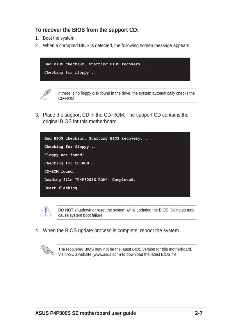
To recover the BIOS from the support CD:1. Boot the system.
2. When a corrupted BIOS is detected, the following screen message appears.
Bad BIOS checksum. Starting BIOS recovery...
Checking for floppy...
3. Place the support CD in the CD-ROM. The support CD contains theoriginal BIOS for this motherboard.
4. When the BIOS update process is complete, reboot the system.
Bad BIOS checksum. Starting BIOS recovery...
Checking for floppy...
Floppy not found!
Checking for CD-ROM...
CD-ROM found.
Reading file “P4P800SS.ROM”. Completed.
Start flashing...
The recovered BIOS may not be the latest BIOS version for this motherboard.Visit ASUS website (www.asus.com) to download the latest BIOS file.
DO NOT shutdown or reset the system while updating the BIOS! Doing so maycause system boot failure!
If there is no floppy disk found in the drive, the system automatically checks theCD-ROM.
2-8 Chapter 2: BIOS information
2.2 BIOS Setup programThis motherboard supports a programmable firmware hub (FWH) that you canupdate using the provided utility described in section “2.1 Managing and updatingyour BIOS.”
Use the BIOS Setup program when you are installing a motherboard, reconfiguringyour system, or prompted to “Run Setup”. This section explains how to configureyour system using this utility.
Even if you are not prompted to use the Setup program, you may want to changethe configuration of your computer in the future. For example, you may want toenable the security password feature or change the power management settings.This requires you to reconfigure your system using the BIOS Setup program sothat the computer can recognize these changes and record them in the CMOSRAM of the firmware hub.
The firmware hub on the motherboard stores the Setup utility. When you start upthe computer, the system provides you with the opportunity to run this program.Press <Delete> during the Power-On Self Test (POST) to enter the Setup utility.Otherwise, POST continues with its test routines.
If you wish to enter Setup after POST, restart the system by pressing <Ctrl> +<Alt> + <Delete>, or by pressing the reset button on the system chassis. You canalso restart by turning the system off and then back on. Do this last option only ifthe first two failed.
The Setup program is designed to make it as easy to use as possible. It is a menu-driven program, which means you can scroll through the various sub-menus andmake your selections from the available options using the navigation keys.
The BIOS setup screens shown in this chapter are for reference purposes only,and may not exactly match what you see on your screen.
Visit the ASUS website (www.asus.com) to download the latest product andBIOS information.
The default BIOS settings for this motherboard apply for most conditions toensure optimum performance. If the system becomes unstable after changingany BIOS settings, load the default settings to ensure system compatibility andstability. Select the Load Default Settings item under the Exit Menu. Seesection “2.7 Exit Menu.”

ASUS P4P800S SE motherboard user guide 2-9
2.2.2 Menu barThe menu bar on top of the screen has the following main items:
Main For changing the basic system configuration
Advanced For changing the advanced system settings
Power For changing the advanced power management (APM)configuration
Boot For changing the system boot configuration
Exit For selecting the exit options and loading default settings
2.2.1 BIOS menu screen
To select an item on the menu bar, press the right or left arrow key on the keyboarduntil the desired item is highlighted.
2.2.3 Navigation keysAt the bottom right corner of a menu screen are the navigation keys for thatparticular menu. Use the navigation keys to select items in the menu and changethe settings.
System Time [11:10:19]System Date [Thu 03/27/2003]Legacy Diskette A [1.44M, 3.5 in]
Primary IDE Master :[ST320413A] Primary IDE Slave :[ASUS CD-S340] Secondary IDE Master :[Not Detected] Secondary IDE Slave :[Not Detected] Third IDE Master :[Not Detected] Fourth IDE Master :[Not Detected] IDE Configuration
System Information
Use [ENTER], [TAB]or [SHIFT-TAB] toselect a field.
Use [+] or [-] toconfigure system time.
Select Screen Select Item+- Change FieldTab Select FieldF1 General HelpF10 Save and ExitESC Exit
Navigation keys
General helpMenu bar
Sub-menu items
Configuration fieldsMenu items
Some of the navigation keys differ from one screen to another.

2-10 Chapter 2: BIOS information
2.2.4 Menu itemsThe highlighted item on the menu bardisplays the specific items for that menu. Forexample, selecting Main shows the Mainmenu items.
The other items (Advanced, Power, Boot,and Exit) on the menu bar have theirrespective menu items.
2.2.5 Sub-menu itemsAn item with a sub-menu on any menu screen is distinguished by a solid trianglebefore the item. To display the sub-menu, select the item and press Enter.
2.2.6 Configuration fieldsThese fields show the values for the menu items. If an item is user- configurable,you may change the value of the field opposite the item. You can not select an itemthat is not user-configurable.
A configurable field is enclosed in brackets, and is highlighted when selected. Tochange the value of a field, select it then press Enter to display a list of options.Refer to “2.2.7 Pop-up window.”
2.2.7 Pop-up windowSelect a menu item then press Enter to display a pop-up window with theconfiguration options for that item.
2.2.8 Scroll barA scroll bar appears on the right side of amenu screen when there are items that donot fit on the screen. Press Up/Down arrowkeys or PageUp/PageDown keys to displaythe other items on the screen.
2.2.9 General helpAt the top right corner of the menu screen is a brief description of the selecteditem.
System Time [11:10:19]System Date [Thu 03/27/2003]Legacy Diskette A [1.44M, 3.5 in]
Primary IDE Master :[ST320413A] Primary IDE Slave :[ASUS CD-S340] Secondary IDE Master :[Not Detected] Secondary IDE Slave :[Not Detected] Third IDE Master :[Not Detected] Fourth IDE Master :[Not Detected] IDE Configuration
System Information
Use [ENTER], [TAB]or [SHIFT-TAB] toselect a field.
Use [+] or [-] toconfigure system time.
Select Screen Select Item+- Change FieldTab Select FieldF1 General HelpF10 Save and ExitESC Exit
Main menu items
Scroll bar
Select Screen Select Item+- Change OptionF1 General HelpF10 Save and ExitESC Exit
Advanced Chipset settings
WARNING: Setting wrong values in the sections below may cause system to malfunction.
Configure DRAM Timing by SPD [Enabled]Memory Acceleration Mode [Auto]DRAM Idle Timer [Auto]DRAm Refresh Rate [Auto]
Graphic Adapter Priority [AGP/PCI]Graphics Aperture Size [ 64 MB]Spread Spectrum [Enabled]
ICH Delayed Transaction [Enabled]
MPS Revision [1.4]
Pop-up window

ASUS P4P800S SE motherboard user guide 2-11
2.3 Main menuWhen you enter the BIOS Setup program, the Main menu screen appears givingyou an overview of the basic system information.
2.3.1 System Time [xx:xx:xxxx]This item allows you to set the system time.
2.3.2 System Date [Day xx/xx/xxxx]This item allows you to set the system date.
2.3.3 Legacy Diskette A [1.44M, 3.5 in.]Sets the type of floppy drive installed. Configuration options: [Disabled] [360K, 5.25in.] [1.2M , 5.25 in.] [720K , 3.5 in.] [1.44M, 3.5 in.] [2.88M, 3.5 in.]
System Time [11:10:19]System Date [Thu 03/27/2003]Legacy Diskette A [1.44M, 3.5 in]
Primary IDE Master :[ST320413A] Primary IDE Slave :[ASUS CD-S340] Secondary IDE Master :[Not Detected] Secondary IDE Slave :[Not Detected] Third IDE Master :[Not Detected] Fourth IDE Master :[Not Detected] IDE Configuration
System Information
Use [ENTER], [TAB]or [SHIFT-TAB] toselect a field.
Use [+] or [-] toconfigure system time.
Select Screen Select Item+- Change FieldTab Select FieldF1 General HelpF10 Save and ExitESC Exit
Refer to section “2.2.1 BIOS menu screen” for information on the menu screenitems and how to navigate through them.
2-12 Chapter 2: BIOS information
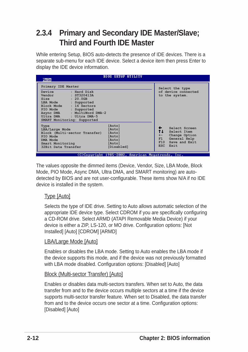
2.3.4 Primary and Secondary IDE Master/Slave;Third and Fourth IDE Master
While entering Setup, BIOS auto-detects the presence of IDE devices. There is aseparate sub-menu for each IDE device. Select a device item then press Enter todisplay the IDE device information.
The values opposite the dimmed items (Device, Vendor, Size, LBA Mode, BlockMode, PIO Mode, Async DMA, Ultra DMA, and SMART monitoring) are auto-detected by BIOS and are not user-configurable. These items show N/A if no IDEdevice is installed in the system.
Type [Auto]
Selects the type of IDE drive. Setting to Auto allows automatic selection of theappropriate IDE device type. Select CDROM if you are specifically configuringa CD-ROM drive. Select ARMD (ATAPI Removable Media Device) if yourdevice is either a ZIP, LS-120, or MO drive. Configuration options: [NotInstalled] [Auto] [CDROM] [ARMD]
LBA/Large Mode [Auto]
Enables or disables the LBA mode. Setting to Auto enables the LBA mode ifthe device supports this mode, and if the device was not previously formattedwith LBA mode disabled. Configuration options: [Disabled] [Auto]
Block (Multi-sector Transfer) [Auto]
Enables or disables data multi-sectors transfers. When set to Auto, the datatransfer from and to the device occurs multiple sectors at a time if the devicesupports multi-sector transfer feature. When set to Disabled, the data transferfrom and to the device occurs one sector at a time. Configuration options:[Disabled] [Auto]
Device : Hard DiskVendor : ST320413ASize : 20.0GBLBA Mode : SupportedBlock Mode : 16 SectorsPIO Mode : SupportedAsync DMA : MultiWord DMA-2Ultra DMA : Ultra DMA-5SMART Monitoring: Supported
Select the typeof device connectedto the system.
Primary IDE Master
Select Screen Select Item+- Change OptionF1 General HelpF10 Save and ExitESC Exit
TypeLBA/Large ModeBlock (Multi-sector Transfer)PIO ModeDMA ModeSmart Monitoring32Bit Data Transfer
[Auto][Auto][Auto][Auto][Auto][Auto][Disabled]

ASUS P4P800S SE motherboard user guide 2-13
PIO Mode [Auto]
Selects the PIO mode. Configuration options: [Auto] [0] [1] [2] [3] [4]
DMA Mode [Auto]
Selects the DMA mode. Configuration options: [Auto] [SWDMA0] [SWDMA1][SWDMA2] [MWDMA0] [MWDMA1] [MWDMA2] [UDMA0] [UDMA1] [UDMA2][UDMA3] [UDMA4] [UDMA5]
SMART Monitoring [Auto]
Sets the Smart Monitoring, Analysis, and Reporting Technology. Configurationoptions: [Auto] [Disabled] [Enabled]
32Bit Data Transfer [Disabled]
Enables or disables 32-bit data transfer. Configuration options: [Disabled][Enabled]
IDE Configuration
Select Screen Select Item+- Change OptionF1 General HelpF10 Save and ExitESC Exit
Onboard IDE Operate Mode [Enhanced Mode] Enhanced Mode Support On [P-ATA]IDE Detect Time Out (Sec) [35]
2.3.5 IDE ConfigurationThe items in this menu allow you to set or change the configurations for the IDEdevices installed in the system. Select an item then press Enter if you wish toconfigure the item.
Onboard IDE Operate Mode [Enhanced Mode]Allows selection of the IDE operation mode depending on the operating system(OS) that you installed. Set to Enhanced Mode if you are using native OS, such asWindows 2000/XP. Set to Compatible Mode if you are using legacy OS includingMS-DOS, Linux, Windows ME/98/NT4.0.Configuration options: [Compatible Mode] [Enhanced Mode]

2-14 Chapter 2: BIOS information
IDE Detect Time Out [35]Selects the time out value for detecting ATA/ATAPI devices. Configuration options:[0] [5] [10] [15] [20] [25] [30] [35]
Enhanced Mode Support On [S-ATA]
The default setting S-ATA allows you to use native OS (Windows 2000/XP) onSerial ATA and Parallel ATA ports. We recommend that you do not change thedefault setting for better OS compatibility. In this setting, you may use legacyOS (Windows ME/98/98SE/NT4.0) on the Parallel ATA ports only if you did notinstall any Serial ATA device.
The P-ATA+S-ATA and P-ATA options are for advanced users only. If you set toany of these options and encounter problems, revert to the default settingS-ATA. Configuration options: [P-ATA+S-ATA] [S-ATA] [P-ATA]
IDE Port Settings [Primary P-ATA+S-ATA]
Allows selection of the IDE ports to activate if you are using a legacy operatingsystem. Set to [Primary P-ATA+S-ATA] if you wish to use the primary ParallelATA and Serial ATA ports, or set to [Secondary P-ATA+SATA] to enable thesecondary P-ATA port instead. Setting to [P-ATA Ports Only] disables the twoSerial ATA ports supported by ICH5. Configuration options: [Primary P-ATA+S-ATA] [Secondary P-ATA+S-ATA] [P-ATA Ports Only]
Refer to the section “Parallel ATA and Serial ATA device configurations” on page1-22 for the appropriate settings of the IDE Configuration items under differentoperating systems.
The Enhanced Mode Support On appears only when the item Onboard IDEOperate Mode is set to Enhanced Mode.
The IDE Port Settings appears only when the item Onboard IDE OperateMode is set to Compatible Mode.

ASUS P4P800S SE motherboard user guide 2-15
Select Screen Select Item+- Change OptionF1 General HelpF10 Save and ExitESC Exit
AMI BIOSVersion : 08.00.08Build Date : 08/01/03
ProcessorType : Intel(R) Pentium(R) 4 CPU 1.73GHzSpeed : 1733 MHzCount : 1
System MemorySize : 256MB
2.3.6 System InformationThis menu gives you an overview of the general system specifications. The itemsin this menu are auto-detected by BIOS.
AMI BIOSThis item displays the auto-detected BIOS information.
ProcessorThis item displays the auto-detected CPU specification.
System MemoryThis item displays the auto-detected system memory.
2.4 Advanced menuThe Advanced menu items allow you to change the settings for the CPU and othersystem devices.
JumperFree Configuration CPU Configuration Chipset Onboard Devices Configuration PCI PnP USB Configuration Instant Music Configuration
Configure CPU.
Select Screen Select ItemEnter Go to Sub-screenF1 General HelpF10 Save and ExitESC Exit
Take caution when changing the settings of the Advanced menu items.Incorrect field values may cause the system to malfunction.

2-16 Chapter 2: BIOS information
When you set the AI Overclocking Tuner item to [Manual], the relatedoverclocking items appear.
If you are using an unlocked CPU, the item CPU Ratio appears under the AIOverclock Tuner item. You may select your desired ratio from the availableoptions.
CPU Ratio [12]This field sets the ratio between the CPU Core Clock and the Front Side Bus (FSB)Frequency.
If an invalid ratio is set in CMOS, the actual and setpoint values may differ.
Performance Mode [Auto]Allows enhanced system performance. Setting to [Turbo] may cause the system tobecome unstable. If this happens, revert to the default setting [Auto]. Configurationoptions: [Auto] [Standard] [Turbo]
2.4.1 JumperFree Configuration
Select Screen Select Item+- Change OptionF1 General HelpF10 Save and ExitESC Exit
AI Overclock Tuner [Standard]
Performance Mode [Auto]
Configure System Frequency/Voltage
AI Overclock Tuner [Standard]Allows selection of CPU overclocking options to achieve desired CPU internalfrequency. Select either one of the preset overclocking options.Configuration options: [Manual] [Standard] [Overclock 5%] [Overclock 10%][Overclock 20%] [Overclock 30%]
Selecting a very high CPU frequency may cause the system to becomeunstable! If this happens, revert to the default setting.

ASUS P4P800S SE motherboard user guide 2-17
Select Screen Select Item+- Change OptionF1 General HelpF10 Save and ExitESC Exit
AI Overclock Tuner [Manual]CPU External Frequency (MHz) [100]DRAM Frequency [Auto]AGP/PCI Frequency (MHz) [Auto]
CPU VCore Voltage [Auto]
Performance Mode [Auto]
Configure System Frequency/Voltage
CPU External Frequency (MHz) [XXX] (value is auto-detected)Indicates the frequency sent by the clock generator to the system bus and PCIbus. The bus frequency (external frequency) multiplied by the bus multiple equalsthe CPU speed. The value of this item is auto-detected by BIOS and is notmanually configurable. The values range from 100 to 400. Refer to the followingtable for the correct Front Side Bus and CPU External Frequency settings.
Front Side Bus CPU External FrequencyFSB 800 200 MHzFSB 533 133 MHzFSB 400 100 MHz
Table 2.4.1 FSB/CPU External Frequency Synchronization
DRAM Frequency [Auto]Allows you to set the DDR operating frequency depending on the CPU installed.Configuration options: [266 MHz] [Auto]: for FSB 400 CPU, [333 MHz] [266MHz][Auto]: for FSB 533 CPU, [533MHz] [500 MHz] [400 MHz] [320 MHz] [266 MHz][Auto]: for FSB 800 CPU.
AGP/PCI Frequency (MHz) [Auto]Allows you to adjust to a higher AGP/PCI frequency for better system performanceand overclocking capability. Configuration options: [Auto] [66.66/33.33][72.73/36.36] [80.00/40.00]
Selecting a very high AGP/PCI frequency may cause the system to becomeunstable! If this happens, revert to the default setting.
Refer to the CPU documentation before setting the CPU VCore voltage. A veryhigh Vcore voltage may severely damage the CPU!
CPU VCore Voltage [Auto]Allows you to select a specific CPU VCore voltage. Configuration options: [Auto][1.9500V] [1.9250V] [1.9000V] [1.8750V] [1.8500V] [1.8250V] [1.8000V] [1.7750][1.7500V] [1.7250V] [1.7000V] [1.6750V] [1.6500V] [1.6250V] [1.6000V]

2-18 Chapter 2: BIOS information
2.4.2 CPU ConfigurationThe items in this menu show the CPU-related information auto-detected by BIOS.
Select Screen Select Item+- Change OptionF1 General HelpF10 Save and ExitESC Exit
Manufacturer : Intel(R)Brand String : Intel(R) Pentium(R) 4 CPU 1.73GHzFrequency : 1733 MHz
Ratio Status : LockedRatio Actual Value : 13
CPUID Maximum Value Limit [Disabled]Hyper Threading Technology [Enabled]
Configure advanced CPU settings
The item Hyper-Threading Technology appears only if you installed an IntelPentium 4 CPU that supports this feature. See page1-11 for details.
2.4.3 ChipsetThe Chipset menu items allow you to change the advanced chipset settings. Selectan item then press Enter to display the sub-menu.
Select Screen Select Item+- Change OptionF1 General HelpF10 Save and ExitESC Exit
Advanced Chipset settings
WARNING: Setting wrong values in the sections below may cause system to malfunction.
Configure DRAM Timing by SPD [Enabled]Memory Acceleration Mode [Auto]DRAM Idle Timer [Auto]DRAm Refresh Rate [Auto]
Graphic Adapter Priority [AGP/PCI]Graphics Aperture Size [ 64 MB]Spread Spectrum [Enabled]
ICH Delayed Transaction [Enabled]
MPS Revision [1.4]
CPUID Maximum Value Limit [Disabled]This item allows you to enable or disable support of older OS for CPU ID maximumvalue limit . Configuration options: [Disabled] [Enabled]
Hyper-Threading Technology [Enabled]This item allows you to enable or disable the processor Hyper-ThreadingTechnology. Configuration options: [Disabled] [Enabled]

ASUS P4P800S SE motherboard user guide 2-19
The following sub-items appear only when the item Configure DRAM Timingby SPD is set to Disabled.
Configure DRAM Timing by SPD [Enabled]When this item is enabled, the DRAM timing parameters are set according to theDRAM SPD (Serial Presence Detect). When disabled, you can manually set theDRAM timing parameters through the DRAM sub-items.Configuration options: [Disabled] [Enabled]
Memory Acceleration Mode [Auto]This field when [Enabled] minimize latencies from CPU to memory to boost systemperformance. Configuration options: [Auto] [Enabled]
If the system becomes unstable after changing the settings of any of the aboveitems, revert to the default settings.
DRAM Idle Timer [Auto]Configuration options: [Infinite] [0T] [8T] [16T] [64T] [Auto]
DRAM Refresh Mode [Auto]Configuration options: [Auto] [15.6 uSec] [7.8 uSec] [64 uSec] [64T]
Setting to [Enabled] may cause the system to become unstable! If thishappens, revert to the default setting [Auto].
DRAM CAS# Latency [2.5 Clocks]
This item controls the latency between the SDRAM read command and thetime the data actually becomes available. Configuration options: [2.0 Clocks][2.5 Clocks] [3.0 Clocks]
DRAM RAS# Precharge [4 Clocks]
This item controls the idle clocks after issuing a precharge command to theDDR SDRAM. Configuration options: [4 Clocks] [3 Clocks][2 Clocks]
DRAM RAS# to CAS# Delay [4 Clocks]
This item controls the latency between the DDR SDRAM active command andthe read/write command. Configuration options:[4 Clocks] [3 Clocks] [2 Clocks]
DRAM Precharge Delay [8 Clocks]
Configuration options: [8 Clocks] [7 Clocks] [6 Clocks] [5 Clocks]
DRAM Burst Length [4 Clocks]
Configuration options: [4 Clocks] [8 Clocks]
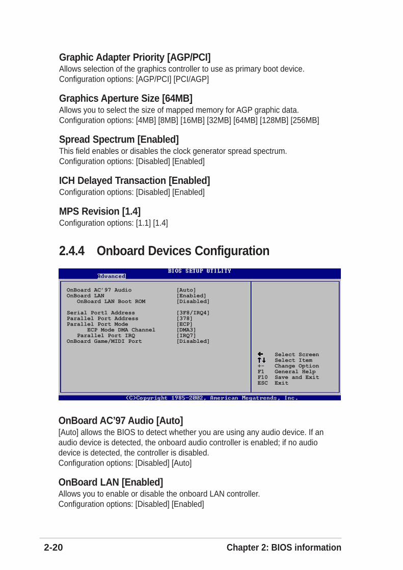
2-20 Chapter 2: BIOS information
Graphic Adapter Priority [AGP/PCI]Allows selection of the graphics controller to use as primary boot device.Configuration options: [AGP/PCI] [PCI/AGP]
Graphics Aperture Size [64MB]Allows you to select the size of mapped memory for AGP graphic data.Configuration options: [4MB] [8MB] [16MB] [32MB] [64MB] [128MB] [256MB]
Spread Spectrum [Enabled]This field enables or disables the clock generator spread spectrum.Configuration options: [Disabled] [Enabled]
ICH Delayed Transaction [Enabled]Configuration options: [Disabled] [Enabled]
MPS Revision [1.4]Configuration options: [1.1] [1.4]
2.4.4 Onboard Devices Configuration
Select Screen Select Item+- Change OptionF1 General HelpF10 Save and ExitESC Exit
OnBoard AC’97 Audio [Auto]OnBoard LAN [Enabled] OnBoard LAN Boot ROM [Disabled]
Serial Port1 Address [3F8/IRQ4]Parallel Port Address [378]Parallel Port Mode [ECP] ECP Mode DMA Channel [DMA3] Parallel Port IRQ [IRQ7]OnBoard Game/MIDI Port [Disabled]
OnBoard AC’97 Audio [Auto][Auto] allows the BIOS to detect whether you are using any audio device. If anaudio device is detected, the onboard audio controller is enabled; if no audiodevice is detected, the controller is disabled.Configuration options: [Disabled] [Auto]
OnBoard LAN [Enabled]Allows you to enable or disable the onboard LAN controller.Configuration options: [Disabled] [Enabled]

ASUS P4P800S SE motherboard user guide 2-21
Serial Port1 Address [3F8/IRQ4]Allows you to select the Serial Port1 base address.Configuration options: [Disabled] [3F8/IRQ4] [2F8/IRQ3] [3E8/IRQ4] [2E8/IRQ3]
Parallel Port Address [378]Allows you to select the Parallel Port base addresses.Configuration options: [Disabled] [378] [278] [3BC]
Parallel Port Mode [ECP]Allows you to select the Parallel Port mode.Configuration options: [Normal] [Bi-directional] [EPP] [ECP]
ECP Mode DMA Channel [DMA3]Configuration options: [DMA0] [DMA1] [DMA3]
Parallel Port IRQ [IRQ7]Configuration options: [IRQ5] [IRQ7]
Onboard Game/MIDI Port [Disabled]Allows you to select the Game Port address or to disable the port.Configuration options: [Disabled] [200/300] [200/330] [208/300] [208/330]
OnBoard LAN Boot ROM [Disabled]
Allows you to enable or disable the option ROM in the onboard LAN controller.This item appears only when the Onboard LAN item is set to Enabled.Configuration options: [Disabled] [Enabled]

2-22 Chapter 2: BIOS information
2.4.5 PCI PnPThe PCI PnP menu items allow you to change the advanced settings for PCI/PnPdevices. The menu includes setting IRQ and DMA channel resources for eitherPCI/PnP or legacy ISA devices, and setting the memory size block for legacy ISAdevices.
Select Screen Select Item+- Change OptionF1 General HelpF10 Save and ExitESC Exit
Plug and Play OS [No]PCI Latency Timer [64]Allocate IRQ to PCI VGA [Yes]Palette Snooping [Disabled]PCI IDE BusMaster [Enabled]
Advanced PCI/PnP settings
WARNING: Setting wrong values in the sections below may cause system to malfunction.
NO: Lets the bIOSconfigure all thedevices in the system.YES: Lets theoperating systemconfigure Plug andPlay (PnP) devices notrequired for boot ifyour system has a Plugand Play operatingsystem.
IRQ3 [Available]IRQ4 [Available]IRQ5 [Available]IRQ7 [Available]IRQ9 [Available]IRQ10 [Available]IRQ11 [Available]IRQ14 [Available]IRQ15 [Available]
Take caution when changing the settings of the PCI PnP menu items.Incorrect field values may cause the system to malfunction.
Plug and Play O/S [No]When set to [No], BIOS configures all the devices in the system. When set to [Yes]and if you installed a Plug & Play operating system, the operating systemconfigures the Plug & Play devices not required for boot.Configuration options: [No] [Yes]
PCI Latency Timer [64]Allows you to select the value in units of PCI clocks for the PCI device latencytimer register. Configuration options: [32] [64] [96] [128] [160] [192] [224] [248]
Allocate IRQ to PCI VGA [Yes]When set to [Yes], BIOS assigns an IRQ to PCI VGA card if the card requests foran IRQ. When set to [No], BIOS does not assign an IRQ to the PCI VGA card evenif requested. Configuration options: [No] [Yes]
Palette Snooping [Disabled]When set to [Enabled], the pallete snooping feature informs the PCI devices thatan ISA graphics device is installed in the system so that the latter can functioncorrectly. Setting to [Disabled] deactivates this feature.Configuration options: [Disabled] [Enabled]

ASUS P4P800S SE motherboard user guide 2-23
The Module Version and USB Devices Enabled items show the auto-detectedvalues. If no USB device is detected, the item shows None.
PCI IDE BusMaster [Enabled]Allows BIOS to use PCI bus mastering when reading/writing to IDE devices.Configuration options: [Disabled] [Enabled]
IRQ xx [Available]When set to [Available], the specific IRQ is free for use of PCI/PnP devices. Whenset to [Reserved], the IRQ is reserved for legacy ISA devices.Configuration options: [Available] [Reserved]
2.4.6 USB ConfigurationThe items in this menu allows you to change the USB-related features. Select anitem then press Enter to display the configuration options.
Select Screen Select Item+- Change OptionF1 General HelpF10 Save and ExitESC Exit
Module Version : 2.22.4-5.3
USB Devices Enabled : None
USB Function [Enabled]Legacy USB Support [Auto]USB 2.0 Controller [Enabled]USB 2.0 Controller Mode [HiSpeed]
USB Mass Storage Device Configuration
USB ConfigurationEnables USB hostcontrollers.
USB Function [Enabled]Allows you to enable or disable USB function. Configuration options: [Disabled][Enabled]
Legacy USB Support [Auto]Allows you to enable or disable support for legacy USB devices. Setting to Autoallows the system to detect the presence of USB devices at startup. If detected,the USB controller legacy mode is enabled. If no USB device is detected, thelegacy USB support is disabled. Configuration options: [Disabled] [Enabled] [Auto]
USB 2.0 Controller [Enabled]Allows you to enable or disable the USB 2.0 controller.Configuration options: [Disabled] [Enabled]

2-24 Chapter 2: BIOS information
The Device and Emulation Type items appear only when there are installedUSB devices.
Select Screen Select Item+- Change OptionF1 General HelpF10 Save and ExitESC Exit
USB Mass Storage Reset Delay [20 Sec]
No USB Mass Storage device detected
Device #1 N/A Emulation Type [N/A] Device #2 N/A Emulation Type [N/A] Device #3 N/A Emulation Type [N/A] Device #4 N/A Emulation Type [N/A] Device #5 N/A Emulation Type [N/A] Device #6 N/A Emulation Type [N/A]
USB Mass Storage Device ConfigurationNumber of secondsPOST waits for the USBmass storage deviceafter that start unitcommand.
USB Mass Storage Device Configuration
USB 2.0 Controller Mode [HiSpeed]Allows you to configure the USB 2.0 controller in HiSpeed (480 Mbps) or FullSpeed (12 Mbps). Configuration options: [Full Speed ] [Hi Speed]
USB Mass Storage Reset Delay [20 Sec]
Allows you to select the number of seconds POST waits for the USB massstorage device after the start unit command. The message “No USB massstorage device detected” appears if none is installed in the system.Configuration options: [10 Sec ] [20 Sec] [30 Sec] [40 Sec]
Emulation Type [N/A]
When set to Auto, USB devices less than 530MB will be emulated as floppydrive, and the remaining drives as hard drives. Forced FDD option can be usedto force an HDD formatted drive to boot as FDD (for example, ZIP drive).
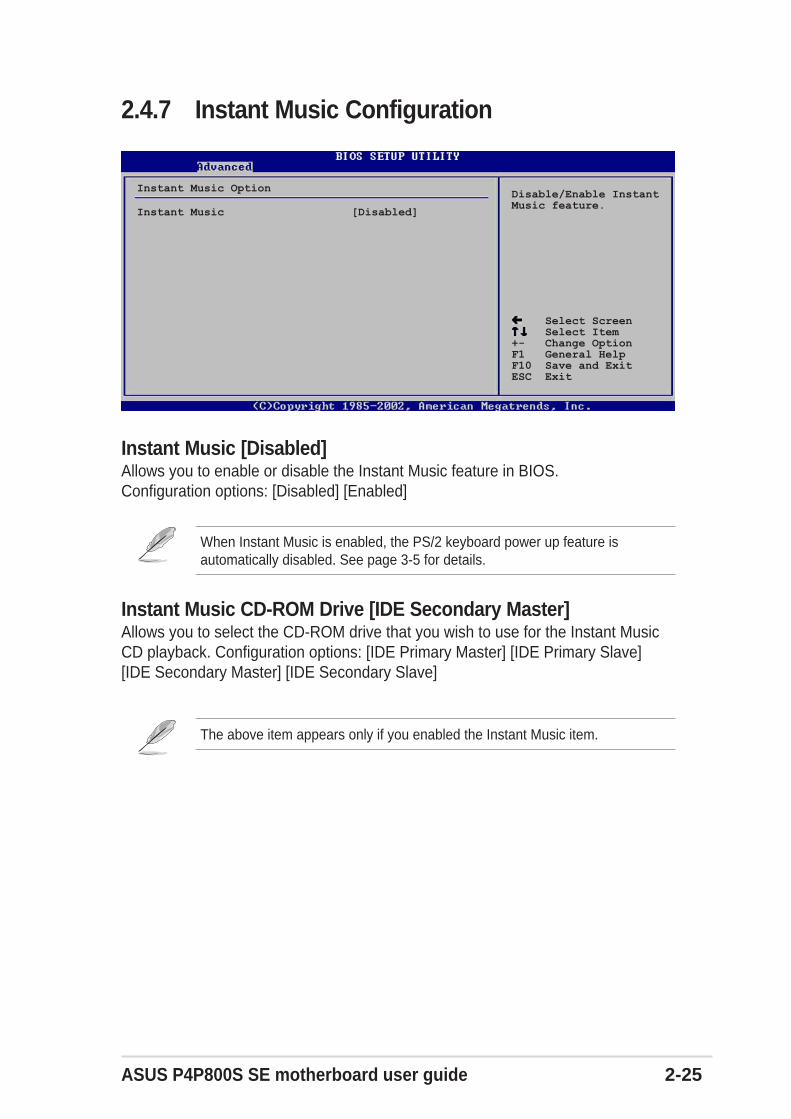
ASUS P4P800S SE motherboard user guide 2-25
Select Screen Select Item+- Change OptionF1 General HelpF10 Save and ExitESC Exit
Instant Music [Disabled]
Instant Music OptionDisable/Enable InstantMusic feature.
2.4.7 Instant Music Configuration
Instant Music [Disabled]Allows you to enable or disable the Instant Music feature in BIOS.Configuration options: [Disabled] [Enabled]
Instant Music CD-ROM Drive [IDE Secondary Master]Allows you to select the CD-ROM drive that you wish to use for the Instant MusicCD playback. Configuration options: [IDE Primary Master] [IDE Primary Slave][IDE Secondary Master] [IDE Secondary Slave]
The above item appears only if you enabled the Instant Music item.
When Instant Music is enabled, the PS/2 keyboard power up feature isautomatically disabled. See page 3-5 for details.
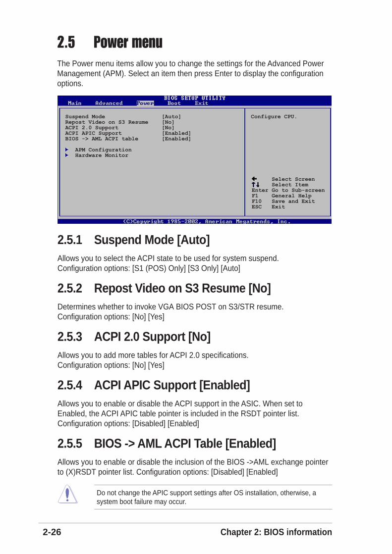
2-26 Chapter 2: BIOS information
2.5 Power menuThe Power menu items allow you to change the settings for the Advanced PowerManagement (APM). Select an item then press Enter to display the configurationoptions.
Suspend Mode [Auto]Repost Video on S3 Resume [No]ACPI 2.0 Support [No]ACPI APIC Support [Enabled]BIOS -> AML ACPI table [Enabled]
APM Configuration Hardware Monitor
Configure CPU.
Select Screen Select ItemEnter Go to Sub-screenF1 General HelpF10 Save and ExitESC Exit
2.5.1 Suspend Mode [Auto]Allows you to select the ACPI state to be used for system suspend.Configuration options: [S1 (POS) Only] [S3 Only] [Auto]
2.5.2 Repost Video on S3 Resume [No]Determines whether to invoke VGA BIOS POST on S3/STR resume.Configuration options: [No] [Yes]
2.5.3 ACPI 2.0 Support [No]Allows you to add more tables for ACPI 2.0 specifications.Configuration options: [No] [Yes]
2.5.4 ACPI APIC Support [Enabled]Allows you to enable or disable the ACPI support in the ASIC. When set toEnabled, the ACPI APIC table pointer is included in the RSDT pointer list.Configuration options: [Disabled] [Enabled]
2.5.5 BIOS -> AML ACPI Table [Enabled]Allows you to enable or disable the inclusion of the BIOS ->AML exchange pointerto (X)RSDT pointer list. Configuration options: [Disabled] [Enabled]
Do not change the APIC support settings after OS installation, otherwise, asystem boot failure may occur.
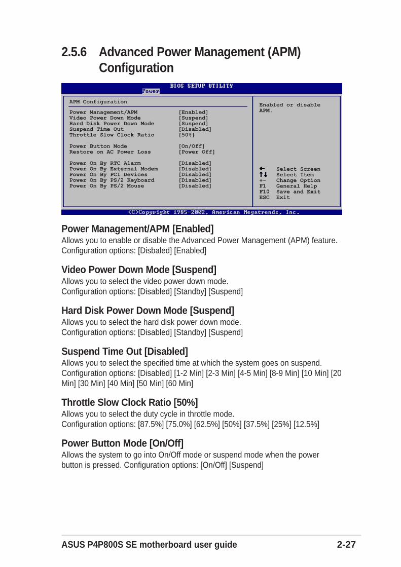
ASUS P4P800S SE motherboard user guide 2-27
Select Screen Select Item+- Change OptionF1 General HelpF10 Save and ExitESC Exit
Power Management/APM [Enabled]Video Power Down Mode [Suspend]Hard Disk Power Down Mode [Suspend]Suspend Time Out [Disabled]Throttle Slow Clock Ratio [50%]
Power Button Mode [On/Off]Restore on AC Power Loss [Power Off]
Power On By RTC Alarm [Disabled]Power On By External Modem [Disabled]Power On By PCI Devices [Disabled]Power On By PS/2 Keyboard [Disabled]Power On By PS/2 Mouse [Disabled]
APM ConfigurationEnabled or disableAPM.
2.5.6 Advanced Power Management (APM)Configuration
Power Management/APM [Enabled]Allows you to enable or disable the Advanced Power Management (APM) feature.Configuration options: [Disbaled] [Enabled]
Video Power Down Mode [Suspend]Allows you to select the video power down mode.Configuration options: [Disabled] [Standby] [Suspend]
Hard Disk Power Down Mode [Suspend]Allows you to select the hard disk power down mode.Configuration options: [Disabled] [Standby] [Suspend]
Suspend Time Out [Disabled]Allows you to select the specified time at which the system goes on suspend.Configuration options: [Disabled] [1-2 Min] [2-3 Min] [4-5 Min] [8-9 Min] [10 Min] [20Min] [30 Min] [40 Min] [50 Min] [60 Min]
Throttle Slow Clock Ratio [50%]Allows you to select the duty cycle in throttle mode.Configuration options: [87.5%] [75.0%] [62.5%] [50%] [37.5%] [25%] [12.5%]
Power Button Mode [On/Off]Allows the system to go into On/Off mode or suspend mode when the powerbutton is pressed. Configuration options: [On/Off] [Suspend]
2-28 Chapter 2: BIOS information
Restore on AC Power Loss [Power Off]When set to Power Off, the system goes into off state after an AC power loss.When set to Power On, the system goes on after an AC power loss. When set toLast State, the system goes into either off or on state whatever was the systemstate before the AC power loss. Configuration options: [Power Off] [Power On][Last State]
Power On By RTC Alarm [Disabled]Allows you to enable or disable RTC to generate a wake event. When this item isset to Enabled, the items RTC Alarm Date, RTC Alarm Hour, RTC Alarm Minute,and RTC Alarm Second appear with set values.Configuration options: [Disabled] [Enabled]
Power On By External Modem [Disabled]This allows either settings of [Enabled] or [Disabled] for powering up the computerwhen the external modem receives a call while the computer is in Soft-off mode.Configuration options: [Disabled] [Enabled]
Power On By PCI Devices [Disabled]When set to [Enabled], this parameter allows you to turn on the system through aPCI LAN or modem card. This feature requires an ATX power supply that providesat least 2A on the +5VSB lead.Configuration options: [Disabled] [Enabled]
Power On By PS/2 Keyboard [Disabled]This parameter allows you to use specific keys on the keyboard to turn on thesystem. This feature requires an ATX power supply that provides at least 2A on the+5VSB lead. Configuration options: [Disabled] [Space Bar] [Ctrl-Esc] [Powerkey]
Power On By PS/2 Mouse [Disabled]When set to [Enabled], this parameter allows you to use the PS/2 mouse to turn onthe system. This feature requires an ATX power supply that provides at least 2A onthe +5VSB lead. Configuration options: [Disabled] [Enabled]
The computer cannot receive or transmit data until the computer andapplications are fully running. Thus, connection cannot be made on the first try.Turning an external modem off and then back on while the computer is offcauses an initialization string that turns the system power on.
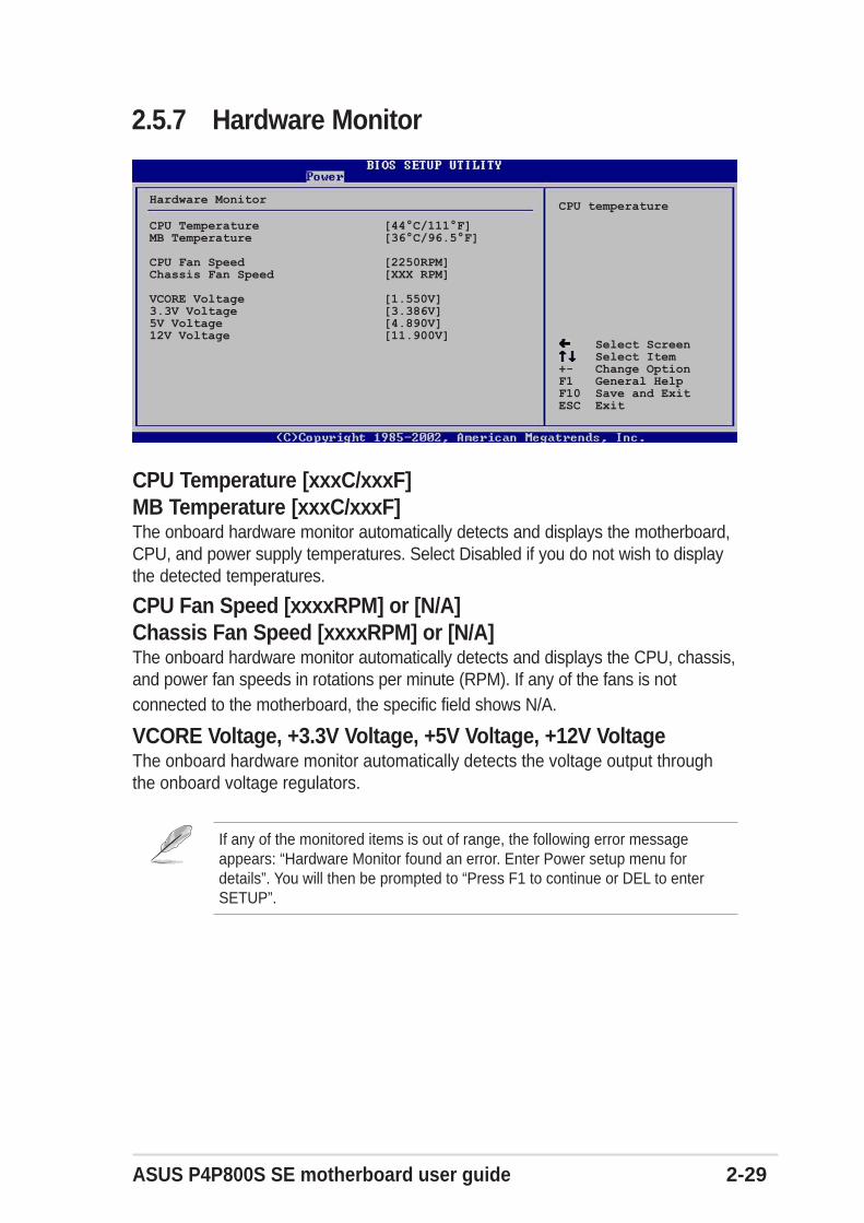
ASUS P4P800S SE motherboard user guide 2-29
Select Screen Select Item+- Change OptionF1 General HelpF10 Save and ExitESC Exit
CPU Temperature [44°C/111°F]MB Temperature [36°C/96.5°F]
CPU Fan Speed [2250RPM]Chassis Fan Speed [XXX RPM]
VCORE Voltage [1.550V]3.3V Voltage [3.386V]5V Voltage [4.890V]12V Voltage [11.900V]
Hardware MonitorCPU temperature
2.5.7 Hardware Monitor
CPU Temperature [xxxC/xxxF]MB Temperature [xxxC/xxxF]The onboard hardware monitor automatically detects and displays the motherboard,CPU, and power supply temperatures. Select Disabled if you do not wish to displaythe detected temperatures.
CPU Fan Speed [xxxxRPM] or [N/A]Chassis Fan Speed [xxxxRPM] or [N/A]The onboard hardware monitor automatically detects and displays the CPU, chassis,and power fan speeds in rotations per minute (RPM). If any of the fans is notconnected to the motherboard, the specific field shows N/A.
VCORE Voltage, +3.3V Voltage, +5V Voltage, +12V VoltageThe onboard hardware monitor automatically detects the voltage output throughthe onboard voltage regulators.
If any of the monitored items is out of range, the following error messageappears: “Hardware Monitor found an error. Enter Power setup menu fordetails”. You will then be prompted to “Press F1 to continue or DEL to enterSETUP”.

2-30 Chapter 2: BIOS information
2.6 Boot menuThe Boot menu items allow you to change the system boot options. Select an itemthen press Enter to display the sub-menu.
Boot Device Priority Removable Drives
Boot Settings Configuration Security
Specifies the BootDevice Prioritysequence.
Boot Settings
Select Screen Select ItemEnter Go to Sub-screenF1 General HelpF10 Save and ExitESC Exit
2.6.1 Boot Device Priority
Select Screen Select Item+- Change OptionF1 General HelpF10 Save and ExitESC Exit
1st Boot Device [1st FLOPPY DRIV]2nd Boot Device [PM-ST320413A]3rd Boot Device [PS-ASUS CD-S340]
Boot Device PrioritySpecifies the bootsequence from theavailable devices.
A device enclosed inparenthesis has beendisabled in thecorresponding typemenu.
1st ~ xxth Boot Device [1st Floppy Drive]These items specify the boot device priority sequence from the available devices.The number of device items that appear on the screen depends on the the numberof devices installed in the system. Configuration options: [xxxxx Drive] [Disabled]

ASUS P4P800S SE motherboard user guide 2-31
2.6.2 Removable Drives
Select Screen Select Item+- Change OptionF1 General HelpF10 Save and ExitESC Exit
1st Drive [1st FLOPPY DRIVE]2nd Drive [PM-ST320413A]3rd Drive [PS-ASUS CD-S340]
Removable DrivesSpecifies the bootsequence from theavailable devices.
A device enclosed inparenthesis has beendisabled in thecorresponding typemenu.
1st ~ xxth Boot Device [(Hard disk drive model name)]These items specify the boot device priority sequence from the availableremovable disk drives. The number of items that appear on the screen depends onthe the number of hard disk drives installed in the system.Configuration options: [xxxxx Drive] [Disabled]
2.6.3 Boot Settings Configuration
Quick Boot [Enabled]Full Screen Logo [Enabled]Add On ROM Display Mode [Force BIOS]Bootup Num-Lock [On]PS/2 Mouse Support [Auto]Typematic Rate [Fast]Boot to OS/2 [No]Wait for ‘F1’ If Error [Enabled]Hit ‘DEL’ Message Display [Enabled]Interrupt 19 Capture [Disabled]
Select Screen Select Item+- Change OptionF1 General HelpF10 Save and ExitESC Exit
Boot Settings ConfigurationAllows BIOS to skipcertain tests whilebooting. This willdecrease the timeneeded to boot thesystem.
Quick Boot [Enabled]Enabling this item allows the BIOS to skip some power on self tests (POST) whilebooting to decrease the time needed to boot the system. When set to [Disabled],BIOS performs all the POST items. Configuration options: [Disabled] [Enabled]
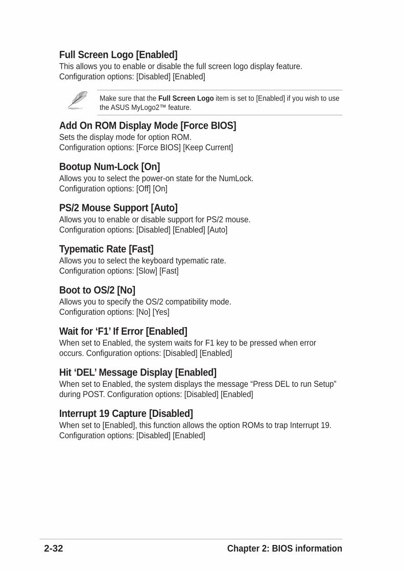
2-32 Chapter 2: BIOS information
Add On ROM Display Mode [Force BIOS]Sets the display mode for option ROM.Configuration options: [Force BIOS] [Keep Current]
Bootup Num-Lock [On]Allows you to select the power-on state for the NumLock.Configuration options: [Off] [On]
PS/2 Mouse Support [Auto]Allows you to enable or disable support for PS/2 mouse.Configuration options: [Disabled] [Enabled] [Auto]
Typematic Rate [Fast]Allows you to select the keyboard typematic rate.Configuration options: [Slow] [Fast]
Boot to OS/2 [No]Allows you to specify the OS/2 compatibility mode.Configuration options: [No] [Yes]
Wait for ‘F1’ If Error [Enabled]When set to Enabled, the system waits for F1 key to be pressed when erroroccurs. Configuration options: [Disabled] [Enabled]
Hit ‘DEL’ Message Display [Enabled]When set to Enabled, the system displays the message “Press DEL to run Setup”during POST. Configuration options: [Disabled] [Enabled]
Interrupt 19 Capture [Disabled]When set to [Enabled], this function allows the option ROMs to trap Interrupt 19.Configuration options: [Disabled] [Enabled]
Make sure that the Full Screen Logo item is set to [Enabled] if you wish to usethe ASUS MyLogo2™ feature.
Full Screen Logo [Enabled]This allows you to enable or disable the full screen logo display feature.Configuration options: [Disabled] [Enabled]

ASUS P4P800S SE motherboard user guide 2-33
2.6.4 SecurityThe Security menu items allow you to change the system security settings. Selectan item then press Enter to display the configuration options.
Supervisor Password Not InstalledUser Password Not Installed
Change Supervisor Password
Boot Sector Virus Protection [Disabled]
Select Screen Select Item+- Change OptionF1 General HelpF10 Save and ExitESC Exit
Security Settings<Enter> to changepassword.<Enter> again todisable password.
Change Supervisor PasswordSelect this item to set or change the supervisor password. The SupervisorPassword item on top of the screen shows the default Not Installed. After youhave set a password, this item shows Installed.
To set a Supervisor Password:
1. Select the Change Supervisor Password item and press Enter.
2. On the password box that appears, type a password composed of letters and/or numbers, then press Enter. Your password should have at least sixcharacters.
3. Confirm the password when prompted.The message “Password Installed” appears after you have successfully setyour password.
The Supervisor Password item now shows Installed.
To change the supervisor password, follow the same steps as in setting a userpassword.
To clear the supervisor password, select the Change Supervisor Password thenpress Enter. The message “Password Uninstalled” appears.
If you forget your BIOS password, you can clear clear it by erasing the CMOSReal Time Clock (RTC) RAM. See section “1.11 Jumpers” for information onhow to erase the RTC RAM.
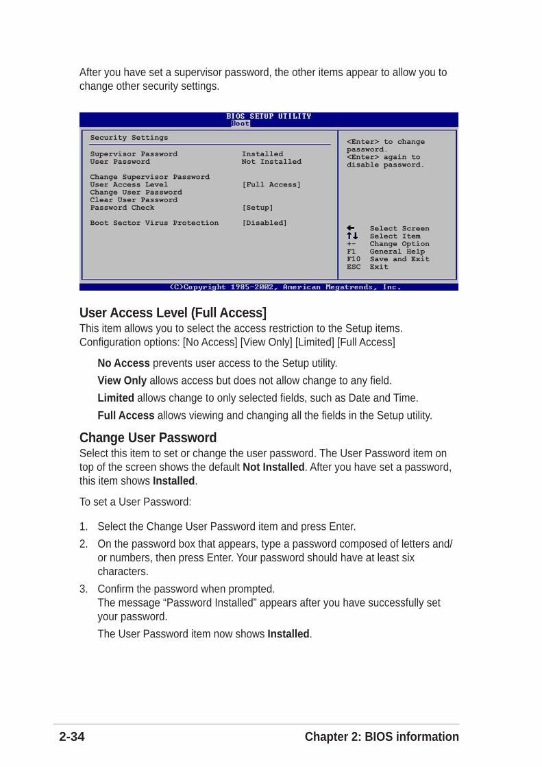
2-34 Chapter 2: BIOS information
User Access Level (Full Access]This item allows you to select the access restriction to the Setup items.Configuration options: [No Access] [View Only] [Limited] [Full Access]
No Access prevents user access to the Setup utility.
View Only allows access but does not allow change to any field.
Limited allows change to only selected fields, such as Date and Time.
Full Access allows viewing and changing all the fields in the Setup utility.
Change User PasswordSelect this item to set or change the user password. The User Password item ontop of the screen shows the default Not Installed. After you have set a password,this item shows Installed.
To set a User Password:
1. Select the Change User Password item and press Enter.
2. On the password box that appears, type a password composed of letters and/or numbers, then press Enter. Your password should have at least sixcharacters.
3. Confirm the password when prompted.The message “Password Installed” appears after you have successfully setyour password.
The User Password item now shows Installed.
Supervisor Password InstalledUser Password Not Installed
Change Supervisor PasswordUser Access Level [Full Access]Change User PasswordClear User PasswordPassword Check [Setup]
Boot Sector Virus Protection [Disabled] Select Screen Select Item+- Change OptionF1 General HelpF10 Save and ExitESC Exit
Security Settings<Enter> to changepassword.<Enter> again todisable password.
After you have set a supervisor password, the other items appear to allow you tochange other security settings.

ASUS P4P800S SE motherboard user guide 2-35
To change the user password, follow the same steps as in setting a user password.
Clear User PasswordSelect this item if you wish to clear the user password.
Password Check [Setup]When set to [Setup], BIOS checks for user password when accessing the Setuputility. When set to [Always], BIOS checks for user password both when accessingSetup and booting the system. Configuration options: [Setup] [Always]
Boot Sector Virus Protection [Disabled]Allows you to enable or disable the boot sector virus protection.Configuration options: [Disabled] [Enabled]
2.7 Exit menuThe Exit menu items allow you to load the optimal or failsafe default values for theBIOS items, and save or discard your changes to the BIOS items.
Exit & Save ChangesExit & Discard ChangesDiscard Changes
Load Setup Defaults
Exit system setupafter saving thechanges.
F10 key can be usedfor this operation.
Exit Options
Select Screen Select ItemEnter Go to Sub-screenF1 General HelpF10 Save and ExitESC Exit
Pressing <Esc> does not immediately exit this menu. Select one of the optionsfrom this menu or <F10> from the legend bar to exit.
Exit & Save ChangesOnce you are finished making your selections, choose this option from theExit menu to ensure the values you selected are saved to the CMOS RAM.The CMOS RAM is sustained by an onboard backup battery and stays oneven when the PC is turned off. When you select this option, aconfirmation window appears. Select [Yes] to save changes and exit.

2-36 Chapter 2: BIOS information
Exit & Discard ChangesSelect this option only if you do not want to save the changes that you made to theSetup program. If you made changes to fields other than system date, systemtime, and password, the BIOS asks for a confirmation before exiting.
Discard ChangesThis option allows you to discard the selections you made and restore thepreviously saved values. After selecting this option, a confirmation appears. Select[Yes] to discard any changes and load the previously saved values.
Load Setup DefaultsThis option allows you to load the default values for each of the parameters on theSetup menus. When you select this option or if you press <F5>, a confirmationwindow appears. Select [Yes] to load default values. Select Exit Saving Changesor make other changes before saving the values to the non-volatile RAM.
If you attempt to exit the Setup program without saving your changes, theprogram prompts you with a message asking if you want to save your changesbefore exiting. Pressing <Enter> saves the changes while exiting.
Chapter 3
This chapter describes the contents of thesupport CD that comes with the motherboardpackage.
Software support
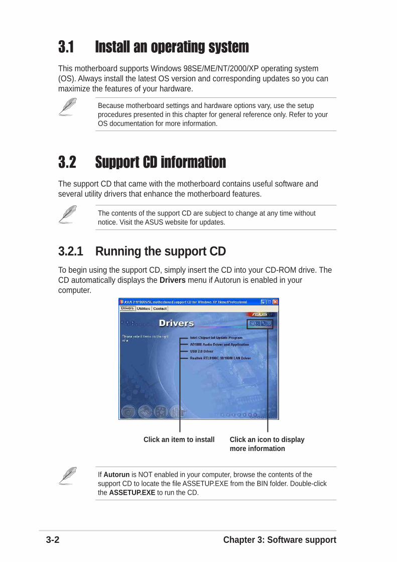
3-2 Chapter 3: Software support
3.1 Install an operating systemThis motherboard supports Windows 98SE/ME/NT/2000/XP operating system(OS). Always install the latest OS version and corresponding updates so you canmaximize the features of your hardware.
Because motherboard settings and hardware options vary, use the setupprocedures presented in this chapter for general reference only. Refer to yourOS documentation for more information.
3.2 Support CD informationThe support CD that came with the motherboard contains useful software andseveral utility drivers that enhance the motherboard features.
3.2.1 Running the support CDTo begin using the support CD, simply insert the CD into your CD-ROM drive. TheCD automatically displays the Drivers menu if Autorun is enabled in yourcomputer.
The contents of the support CD are subject to change at any time withoutnotice. Visit the ASUS website for updates.
If Autorun is NOT enabled in your computer, browse the contents of thesupport CD to locate the file ASSETUP.EXE from the BIN folder. Double-clickthe ASSETUP.EXE to run the CD.
Click an icon to displaymore information
Click an item to install

ASUS P4P800S SE motherboard user guide 3-3
3.2.2 Drivers menuThe drivers menu shows the available device drivers if the system detects installeddevices. Install the necessary drivers to activate the devices.
Intel® Chipset Inf Update programThis item installs the Intel® Chipset INF Update Program that enables Plug-n-PlayINF support for Intel chipset components. This utility installs to the target systemthe Windows INF files that outline to the operating system how the chipsetcomponents will be configured. Refer to the online help or readme file that camewith the utility.
ADI AD1888 Audio Driver and ApplicationThis item installs the ADI AD1888 audio driver and application to activate the6-channel audio feature.
3.2.3 Utilities menuThe Utilities menu shows the applications and other software that the motherboardsupports.
Windows NT supports 2-channel audio only.
USB 2.0 Driver
This item installs the USB 2.0 driver.
REALTEK RTL8100C 10/100M LAN DriverThis item installs the Realtek LAN driver to support 10/100 Mbps networking.
The Realtek RTL8101L LAN driver is required for Windows® 98SE only.

3-4 Chapter 3: Software support
ASUS PC ProbeThis smart utility monitors the fan speed, CPU temperature, and system voltages,and alerts you on any detected problems. This utility helps you keep your computerat a healthy operating condition.
Install ASUS UpdateThis program allows you to download the latest version of the BIOS from the ASUSwebsite. Before using the ASUS Update, make sure that you have an Internetconnection so you can connect to the ASUS website. Installing ASUS Update alsoinstalls ASUS Mylogo™.
3.2.4 ASUS Contact InformationClicking the ASUS Contact Information tab displays as stated. You may also findthis information on page viii of this user guide.
PC-CILLIN 2002This item installs the PC-cillin 2002 anti-virus program. View the PC-cillin onlinehelp for detailed information.
Adobe Acrobat ReaderThis item installs the Adobe Acrobat Reader V5.0. The Acrobat Reader software isfor viewing files saved in Portable Document Format (PDF).
ASUS Screen SaverThis item installs the ASUS screen saver.
To use the MyLogo™ feature, set the BIOS “Quick Boot” item to [Enabled]. Seesection “2.6.3 Boot Settings Configuration” in page 2-32.

ASUS P4P800S SE motherboard user guide 3-5
3.3 ASUS Instant Music LiteThe motherboard is equipped with a BIOS-based audio playback feature calledInstant Music Lite. This feature is supported by the onboard audio AC’97CODEC, and requires an optical drive (CD-ROM, DVD-ROM, or CD-RW).
To enable ASUS Instant Music Lite:
1. Connect the analog audio cable from the optical drive (CD-ROM, DVD-ROM,or CD-RW drive) to the 4-pin CD-In connector (labeled CD1) on themotherboard. See section “1.12 Connectors” for the connector location.
5. Save your changes and exit BIOS Setup.
If you have only one optical drive (either CD-ROM, DVD-ROM, or CD-RW)installed in the system, you don’t have to set Instant Music CDROM item. BIOSautomatically detects and displays the installed drive type.
2. Turn on the system and enter BIOS by pressing the Delete key during thePower On Self-Tests (POST).
3. In the Advanced Configuration menu, select the item Instant Music and setit to Enabled. See section “2.4 Advanced Menu” in the user guide.
4. Highlight the Instant Music CDROM item and press Enter to display theCD-ROM options. Select the CD-ROM drive that you wish to use for thisfeature. See section “2.4 Advanced Menu” in the user guide.
Make sure to connect the CD-ROM audio cable. Otherwise, you cannot controlthe audio volume using the Instant Music Lite function keys.
1. Instant Music Lite only supports CDs in audio format.2. Instant Music Lite does not work if you installed and enabled an add-on
sound card.3. Instant Music Lite only supports PS/2 keyboard.
1. The Scroll Lock LED is fixed to ON after enabling Instant Music.2. The Caps Lock LED is turns ON when you pause the CD playback.3. When set to Instant Music Lite mode, the system wake-up features (LAN,
keyboard, mouse, USB) are deactivated. In this case, power up the systemusing the power switch.
4. If the system lost connection or did not detect any optical drive, the InstantMusic Lite feature turns OFF (disabled) automatically. A “beep” indicatesthis condition.

3-6 Chapter 3: Software support
To use ASUS Instant Music Lite:
1. Ensure that the power cord is plugged to a grounded power source, so that thesystem has a standby power.
2. Use either one of the two sets of special function keys on your keyboard toplay audio CDs. These keys only function as indicated if you enabled theInstant Music Lite in BIOS.
Instant Music function keys (Set 1)
Instant Music function keys (Set 2)
3. Connect speakers or a headphone to the Line Out (lime colored) port on therear panel for audio output. You may also connect a headphone to theheadphone jack on the CD-ROM drive front panel.
4. Place an audio CD on the drive.
5. Press Esc to turn ON Instant Music Lite.
6. Press F1 or the Space Bar to play the first track on the CD.
If there is no CD on the drive and you press F1 or Space Bar, the drive trayejects.
7. Refer to the Instant Music function key definitions on the previous page toselect other tracks or control the volume.
8. Press F2 or Enter once to stop playing the CD.Press F2 or Enter one more time to eject the CD.
CD ON/OFF
PLAY/PAUSE STOP/EJECT PREVIOUS NEXT
VOL. DOWN VOL. UP
SCROLLLOCKLED
CAPSLOCKLED
CDON/OFF PLAY/PAUSE STOP/EJECT PREVIOUS NEXT VOL. DOWN VOL. UP
Esc F1 F2 F3 F4 F5 F6 F7 F8