P4 Country v2 - 4power4 · You recently acquired a P4 Country Off-Road Electric Wheelchair, and we...
48
P4 Country v2 Electric Wheelchair for roads and paths USER GUIDE
Transcript of P4 Country v2 - 4power4 · You recently acquired a P4 Country Off-Road Electric Wheelchair, and we...

P4 Country v2 Electric Wheelchair for roads and paths
USER GUIDE

2
CERTIFICATE OF GUARANTEE /CUSTOMER SATISFACTION ENQUIRY – P4 COUNTRY Please return to :
4 poWer 4 Baron de Castro 16 B-1040 Bruxelles
Belgium
Name .......................... First name .......................... Questionnaire answered on .......................... Address .............................................................................................................................................. Tel. N° SS N°…../………/…..…/….…/………../……./ /….../ Date of birth .............................. Height ............ Weight ......... Pathology ....................................... Wheelchair serial N° ........................ Dealer’s address ............................................................................................................................... E-mail address ...................................................................................................................................
******************************************************
Customer Satisfaction Enquiry Dear Customer, You recently acquired a P4 Country Off-Road Electric Wheelchair, and we thank you for your trust in our products. We would appreciate your remarks or suggestions as a P4 Country user. By filling in this questionnaire and returning it to us, you will help us to match our products and services to your needs.
Is this your first off-road wheelchair ? YES NO If NO, what make was the previous one ? .................................................... Reason for changing Wheelchair worn out Wheelchair not adapted Evolution of needs Other (please specify) Getting to know the product 1) How did you learn of our products ? Magazine ad (which magazine ?) .............................................................................. Recommended by : Your dealer Your friends & family Demonstration in a Center. Which one ? .................................................................... Demonstration at an Exhibition. Which one ? ............................................................. Internet Other .......................................................................................................................... 2) Did the documentation seem to you Insufficient Suitable Complete 3) Did our brochures provide you with enough technical information? YES NO 4) Did your dealer provide you with all the information you required concerning our wheelchair ? YES NO 5) Did you have a demonstration : With the dealer With our salesperson Both Neither

3
Ordering and installing 6) The delivery deadline given was ______ days. 7) Did this seem to you : Too long Normal Short Very short 8) Was this deadline met ? YES NO, exceeded by _______ days. 9) The adjustments were made by : The dealer Our salesperson Adjustments made in-works
10) How do you rate our dealer service ?
Poor Average Good Excellent The wheelchair 11) For you, this wheelchair serves as : An everyday wheelchair A leisure wheelchair Both 12) In your opinion, the wheelchair handles : Poorly Well enough Well Outstandingly well 13) In your opinion, the wheelchair rides Poorly Well enough Well Outstandingly well 14) How do you rate the seat tilt function of the wheelchair ? Poor Passable Good Excellent 15) How do you rate the off-road capacity of the wheelchair ? Poor Passable Good Excellent 16) How do you rate the wheelchair for comfort ? Poor Passable Good Excellent 17) Does your wheelchair live up to your expectations ? YES NO If NO, why not? ........................................................................................................................ 18) What pleased you most in your wheelchair ? ................................................................................................................................................ 19) What part or function disappointed you ? ................................................................................................................................................ 20) In your opinion, what part(s) or function(s) could be improved, and how ? ................................................................................................................................................ After Sales Service 21) Did you need After Sales Service ? YES NO 22) If YES, how was it ? Satisfactory Average Below standard Please share any observations or comments with us : ............................................................................................................................................................ ............................................................................................................................................................
THANK YOU FOR HAVING ANSWERED THIS QUESTIONNAIRE

4
INDEX
INTRODUCTION ....................................................................................................................... 7 A - Taking delivery of your chair ................................................................................................ 7 B - Guarantee ............................................................................................................................ 7 Presentation of the P4 COUNTRY all road wheelchair .............................................................. 8
.................................................................. 8 Chapter I : Adjusting the wheelchair to the user’s needs. .......................................................... 9 1 - Seat adjustment ................................................................................................................... 9
1.1 - Seat depth ..................................................................................................................... 9 1.2 - Adjusting the tilt and the width of the backrest ............................................................. 10
2 - Footrest unit ....................................................................................................................... 11
2.1 - Footrest height ............................................................................................................. 11 2.2 - Footrest tilt ................................................................................................................... 11
2.3 - Footrest depth .............................................................................................................. 12 2.4 - Footrest tilt ................................................................................................................... 12
3 - Armrest unit ........................................................................................................................ 13 3.1 - Armrest height ............................................................................................................. 13
3.2 - Armrest spacing ........................................................................................................... 13 3.3 - Armrest depth .............................................................................................................. 14
4 – Joystick remote .................................................................................................................. 14
Chapter II : Safety .................................................................................................................... 15

5
2 - Driving recommendations ................................................................................................... 15
2.1 - General ........................................................................................................................ 15 2.2 - Speed .......................................................................................................................... 15 2.3 - Obstacles and slope sensor ......................................................................................... 15
2.4 – Water resistance ......................................................................................................... 16 2.5 - Collision ....................................................................................................................... 16 2.6 - Safety belt .................................................................................................................... 16
Chapter III: First contact .......................................................................................................... 17 3.1 - Getting in and out of the wheelchair ............................................................................ 17
3.1.1 - Getting into the wheelchair .................................................................................... 17 3.1.2 - Getting out of the wheelchair ................................................................................. 17
3.2 – Circuit breaker ............................................................................................................. 17 3.3. DX2 joystick remote operation ...................................................................................... 18
3.3.1.General view ........................................................................................................... 18
3.3.2 The screen layout .................................................................................................... 18 3.3.3.1. The Status Bar .................................................................................................... 19
3.3.3.4 The Time Clock .................................................................................................... 19 3.3.3.5 Road Light ............................................................................................................ 19 3.3.3.6 Hazard .................................................................................................................. 19
3.4 - Turning the DX System on and off with the joystick remote ......................................... 19
3.5 - System Lock ................................................................................................................ 20 3.6 - Sleep mode .................................................................................................................. 20 3.7 - Menu Navigation Modes .............................................................................................. 20
3.7.1 Standard Mode ........................................................................................................ 20 3.7.2 Pre-set profiles ........................................................................................................ 21
Chapter IV – Driving ................................................................................................................ 23
4.1 – A safe environment ..................................................................................................... 23
4.2 – Remote joystick ........................................................................................................... 23 4.3 - Braking in the wheelchair ............................................................................................. 23
4.4 - Autonomy of the wheelchair ......................................................................................... 24 4.5 – Tilt in space position ................................................................................................... 24 4.6 – Top case ..................................................................................................................... 26
Chapter V : Maintenance ......................................................................................................... 28 5.1.1 - Batteries ................................................................................................................ 28
5.1.2 - Use and Charge of the Batteries ........................................................................... 28 5.1.3. Complete charge: ................................................................................................... 29
5.2 : Charger ........................................................................................................................ 29
5.3: Long term storage of the wheelchair when not in use ................................................... 30 5.4 – Wheels and motors ..................................................................................................... 31
5.4.1 - Engaging and disengaging the motors .................................................................. 31 5.4.2 - Changing a wheel.................................................................................................. 32
5.5 - Cleaning....................................................................................................................... 36 5.6 - Error codes on status display ....................................................................................... 36
Chapter VI : Transport ............................................................................................................. 37 6.1 – Anchorage point .......................................................................................................... 37 6.2 – Folding safety rollbar ................................................................................................... 38
Chapter VII : P4 COUNTRYv2 specifications data .................................................................. 39 1 - Specifications particular to the wheelchair ......................................................................... 39 2 - Driving system specifications ............................................................................................. 39 3 - Electrical circuit specifications ............................................................................................ 39 4 - Dimensions and weight ...................................................................................................... 39
7.5 – Electric wiring .............................................................................................................. 40

6
Chapter VIII : Standards and Certification ............................................................................... 41
8.1 - Electromagnetic compatibility ...................................................................................... 41 8.2 - EC Standard tested ..................................................................................................... 41 8.3 - Waste management ..................................................................................................... 41
P4 COUNTRY CERTIFICATE OF GUARANTEE .................................................................... 42 P4 COUNTRY SERVICING LOGBOOK .................................................................................. 43
7
INTRODUCTION
You have just acquired a P4 Country Electric Off-Road Wheelchair. We hope it gives you complete satisfaction. Before using, it is essential that you study this User Guide. It contains advice for use and maintenance that will guarantee your safety.
A - Taking delivery of your chair
On receiving your chair, you must check that neither the outer packaging nor the contents are damaged. If damage has occurred, contact your dealer at once. Failure to do so will make it impossible to consider any claims.
B - Guarantee
Please return the Guarantee card to us as soon as possible so that we may intervene if necessary. We are at your disposal for any remarks or suggestions you may have and for any further information you may require.

8
Presentation of the P4 COUNTRY all road wheelchair
This P4 COUNTRY Electric All-Road wheelchair has been designed for greater functionality and optimum quality of life. This electric wheelchair has been designed for both indoor use (house, flat, workplace …) and outdoors (leisure, public roads) with the ability to clear pavements and obstacles of up to 15 cm. (6 inches). For use on public roads, refer to your dealer who will provide you with all relevant information for registering this product in your country. Before use involving climbs and obstacles, it is essential you refer to the “Safety” chapter. You will find all necessary information about the wheelchair’s technical data (autonomy, top speed, maximum practicable slope …) in the “Specifications” chapter.
Circuit
Breaker
Charger
Socket

9
Chapter I : Adjusting the wheelchair to the user’s needs.
The adjustments below are to be made with regard to the user’s build so as to ensure best possible use of the wheelchair.
1 - Seat adjustment
1.1 - Seat depth
For increased comfort, the seat can be adapted to the user’s thigh length. Adjustment to be made while the chair is unoccupied: Loosen the screws (1), slide the footrests (2) forwards to obtain the desired seat depth and replace the screws. Press on the part located below the front of the seat so as to free the seat length. Slide the parts (2) towards the rear and tighten the screws.
1 2
10
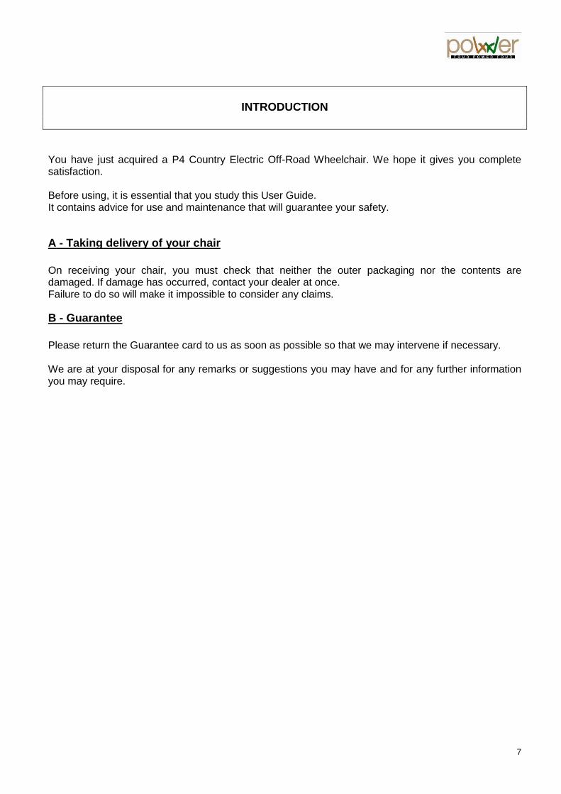
1.2 - Adjusting the tilt and the width of the backrest
For good support and comfort, tilt and width of the backrest can be adapted to thhe user’s build. Adjustments to be made with the user in place : The front part of the seat moves forwards or backwards. Just press the handle below the front seat. The knob (2) allows you to adjust the backrest tilt. This tilt must be adjusted with the rollbar in place and the top case locked on its base. The knob (3) allows you to adjust the spacing of the backrest’s side supports. The knob (4) allows you to fold the seat forward completely by raising it during transport for example. Finally, the headrest can be adjusted manually for height and tilt. The headrest folds away by pressing firmly at the points indicated below:
4
3
2
1

11
2 - Footrest unit
2.1 - Footrest height
The aluminium footrest is height adjustable. To do this, remove the support fitting screws and position the support at the desired height then replace the screws. As a guide, good adjustment allows the best possible pressure distribution under the thigh.
2.2 - Footrest tilt
To adjust the footrest tilt, manoeuvre the lever which is incorporated in the support.
Fitting screws
Lever

12
2.3 - Footrest depth
To adjust the depth of the footrests, loosen the knob. Position it at the required depth, then re-screw the knob.
2.4 - Footrest tilt
To adjust the footplate angle, use the built-in thrust screws.
Knob screw
Thrust screws

13
3 - Armrest unit
3.1 - Armrest height
Loosen the armrest knob, adjust armrest to the desired height and re-screw the knob.
3.2 - Armrest spacing
Loosen the armrest guide track knob, adjust to the desired spacing and re-screw the knob.
Knob screws
Knob screws

14
3.3 - Armrest depth
Remove the armrest holding screws, adjust the armrest to the desired depth, and screw in position.
4 – Joystick remote
To adjust the joystick remote depth, loosen the knob and position at the required depth. Note: the joystick remote unit is suitable for right handed or left handed use.
Holding screws
Knob
srews

15
2 - Driving recommendations
2.1 - General
- Warning ! There is a risk of injury if the wheelchair is not used as indicated in the operating instructions. - Switch the wheelchair off, with engine brakes engaged, before transferring in or out. - Do not drive this chair when under the influence of medication, drugs, alcohol or any other substances harmful to the safety of the user or persons in their vicinity. - Be vigilant regarding other people’s safety when using the chair on public roads and especially on pavements. - Maximum user weight should not exceed 120 kilos (275 lbs). - Do not attempt to go down or up stairs in the chair. - Do not transport a third person in or on your wheelchair. - When using the chair on public roads, you should check that the lights and indicators in working order.
2.2 - Speed
- Driving speed should be adapted to the terrain. - The user should observe the highway code, speed limits and road signs, and comply with the law in force in each country for this type of vehicle. - When driving on pavements, the chair’s speed should be adapted to that of pedestrians. - As soon as the seat is inclined, maximum speed is reduced to guarantee user safety. - When avoiding obstacles or contours, speed must be reduced, otherwise the chair may easily tip. The same is true in bends or U-turns. This risk is greatest when the bend is combined with a camber. You are urged to take the utmost care, and proceed at minimum speed.
2.3 - Obstacles and slope sensor
- Do not attempt to clear obstacles over 6 inches high - Always clear obstacles in seated position and approach the obstacle at right angles. - Return your backrest to the upright position before clearing an obstacle. - Approach the obstacle slowly and preferably in the presence of an attendant person. - On upward slopes, always lean forward and avoid all abrupt changes of direction. Do not negotiate upward slopes steeper than 30%. - On downward slopes, always lean backwards and opt for a low gear. Do not negotiate downward slopes steeper than 30%. - To limit the risk of falls, do not negotiate slopes that are too steep, too long (excess impetus causing loss of control) or banked slope (risk of tipping). - Do not drive on transverse slopes steeper than 20% (risk of tipping). - Avoid braking abruptly on a slope : risk of tipping. - The chair is fitted with an slope sensor. This device is for preventive purposes and does not absolve the user of responsibility in the event of an accident or attempting too steep slopes or dangerous obstacles. - Two signals inform the user about the slope they are on.
Chapter II : Safety

16
One beep per second as well as the blinking of the LED on the joystick shows that the user is on ground of which the frontal or lateral slope is becoming dangerous for their safety, with risk of tipping. The user should adjust speed and withdraw from this zone immediately at the lowest possible speed. A continuous beep with all LEDs flashing means the user is in a very dangerous zone and their safety is imperilled. The user should then bring the chair to a standstill and request assistance from a attendant person to guide and hold the chair in position to avoid all risk of tipping. - This slope sensor is solely for informative purposes. You should not use it as your sole guide. Use your judgment to decide whether a slope or an obstacle can be cleared.
2.4 – Water resistance
- The various chair components are not completely waterproof. You should therefore use the chair when conditions permit and present no risk of damaging electrical circuits or any other components. - The chair must be kept out of water. - Sand, gravel, earth or mud can damage the operation of the chair. - Make sure you protect the various features of the chair.
2.5 - Collision
- After a collision involving your chair, it is imperative that each feature be checked before re-use. - In the event of a serious collision, contact your dealer at once, even if damage is not apparent.
2.6 - Safety belt
For safety purposes, the chair brakes rapidly. This improves user and pedestrian safety. It is therefore essential that the person seated in the chair fasten the safety belt. This belt will both hold in position and secure the person in the event of sudden braking.

17
Chapter III: First contact
3.1 - Getting in and out of the wheelchair
Your doctor and/or therapist will show you how to transfer depending on your way of life and your state of health. For ease of lateral transfer, this wheelchair is equipped with removable armrests. To remove the armrests, refer to the chapter ‘Adjustment and adaptation of the wheelchair to the user’s needs’ and follow the procedure ‘3.2 –Armrest spacing completely removing the armrests in the process.
3.1.1 - Getting into the wheelchair
- switch off the wheelchair - remove the armrest - position your seat as near as possible to the wheelchair for the transfer - transfer
3.1.2 - Getting out of the wheelchair
- switch off the wheelchair - remove the armrest - position the wheelchair as near as possible to the seat you now wish to transfer into - transfer
WARNING ! If your muscle strength is insufficient, it is imperative you ask other people for help with the transfer.
3.2 – Circuit breaker
Switch « on » the circuit breaker, located below your left knee,
18
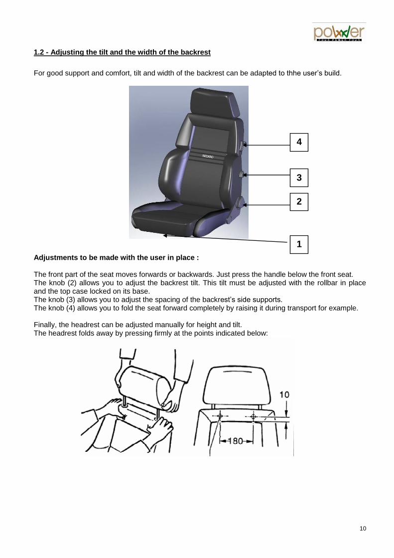
3.3. DX2 joystick remote operation
3.3.1.General view
The
keypad
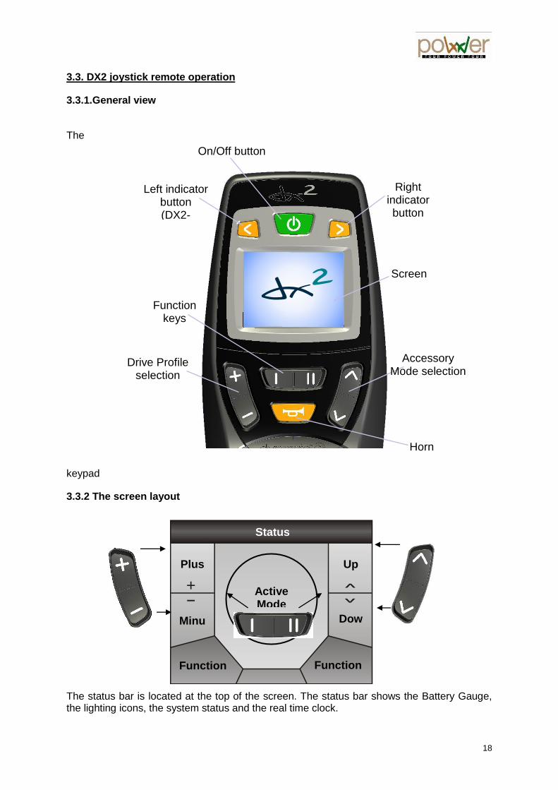
3.3.2 The screen layout
The status bar is located at the top of the screen. The status bar shows the Battery Gauge, the lighting icons, the system status and the real time clock.
On/Off button
Left indicator button (DX2-
REM550)
Screen
Right indicator button (DX2-
REM550)
Function keys
Horn
Accessory Mode selection
Drive Profile selection
+ Active Mode
Function FunctionII
Status Bar
Plus
Minuss
Up
Downn

19
The area at the centre of the screen shows the mode that is currently active. The areas at the side of the screen show the modes that will become active if the menu navigation buttons are pressed.
3.3.3.1. The Status Bar
3.3.3.2 The System Status
The System Status icon is normally hidden. If a fault occurs, a wrench icon will show, together with the fault code number. See the DX System Manual for a description of the fault codes.
3.3.3.3. The Lighting Icons
The indicator icons and the side light icon will show when the lights are on.
3.3.3.4 The Time Clock
The real time clock shows the time in 24-hour format. The time can be adjusted with the On-Board Programming menu.3.3.3.5 Road Light
To put the lights “ON” press more than 5 secondes on the leftt turn lighting To switch “off”, press again the same button.
3.3.3.6 Hazard
To activate “hazard” press more than 5 secondes on the right turn lighting To switch “off”, press again the same button.
3.4 - Turning the DX System on and off with the joystick remote
To turn on the DX System
Press the power button.
The joystick remote will beep twice and the system will start up in with the Drive
Profile that has been set.
Battery Gauge
Left Indicator
Active
Right Indicator
Active
Real Time Clock
System Status
Hazard Lights Active
3 Fault Code
Side Light Active

20
To turn off the DX System
Press the power button.
The DX System will turn off.
Note:
If the power button is pressed while the chair is driving,
the chair will perform an emergency stop before it turns off.
3.5 - System Lock
If the Lock Enable parameter (see DSM section 5.3.9.7) is set to 'Yes', the system can be locked by pressing the power button for more than 4 seconds.
To lock the DX System
Press the power button for 4 seconds when the DX System is turned on.
The DX System will turn off in locked state.
To unlock the DX System
Press the power button.
The joystick remote will show a lock on the display.
Press the horn button twice within 10 seconds.
The DX System will switch on normally.
3.6 - Sleep mode
If the Sleep Mode Enable parameter (see DSM 5.3.9.8) is set to 'Yes', the DX System will go into sleep mode after a period of inactivity. This period can be set with the Sleep Timeout parameter (see DSM
5.3.8.5). When the DX System sleeps, it is partially turned off to reduce energy consumption.
To wake up the DX System
Any key
or
Joystick
Press any button on the AJR, or, if the Enable Joystick Wakeup parameter
(see DSM 5.3.9.10) is set to 'Yes', move the joystick.
The DX System will turn on.
3.7 - Menu Navigation Modes
3.7.1 Standard Mode
In standard Mode use the plus/minus key and the up/down button for menu navigation. Some functions can be accessed directly with other buttons (for example the indicator buttons or the function button). The joystick is used in some modes to operate within that mode, for example in the Actuator Mode the joystick operates a selected actuator.
2 x

21
In this manual, a menu map is included with each Menu Mode. The menu map shows the exact menu navigation for each mode.
3.7.2 Pre-set profiles
You have 5 pre-set profiles: Profile 1: indoors - precision placing. Profile 2: indoors - room transfer. Profile 3: outdoors - urban driving at pedestrian speed. Profile 4: outdoors – full power fast steering for advanced urban driving. Profile 5: outdoors – full power soft steering for driving on rough ground.
Current Drive Profile
Current Speed
Maximum Speed
Select Actuators (Accessory
Mode)
Select Screen Settings - OPB
(Accessory Mode)
Select next Drive Profile
Select previous
Drive Profile
Speed profil

22
Note : on some version a gyroscope is available. The gyroscope is activated on profile 5 only.

23
Chapter IV – Driving
4.1 – A safe environment
Before each ride, check 3 essential points:
- Make sure all controls can be easily reached. - Make sure the batteries are charged enough for the ride. - Make sure the safety belt is in good condition.
- Choose the lowest speed (Profile « 1 ») and remain watchful. - Start driving in a familiar environment
4.2 – Remote joystick
The direction taken by the wheelchair depends on the movement of the joystick. Pushed forwards : the wheelchair moves straight ahead. Pushed to the right : the wheels turn to the right, then use the joystick to indicate direction. Pushed to the left : the wheels turn to the left, then use the joystick to indicate direction. Pushed backwards : the wheelchair reverses.
4.3 - Braking in the wheelchair
To brake, all you need to do is release the joystick. The joystick returns to neutral. For emergency braking, move the joystick to “reverse” position.

24
4.4 - Autonomy of the wheelchair
The autonomy of your wheelchair depends on the batteries capacity of the wheelchair. To summarize, on flat ground is about 20 km with 110 Amp, 30 km with lithium 160 Ah and more than 40 with gel 200 Ah. This autonomy is subject to the influence of various factors. In practice the road condition, inclines, driving mode, use of lights, tyre pressure, total transported weight, outdoor temperature are some of the elements to be considered. The way the batteries are charged has a considerable influence on the energy consumption and thus affects the rapidity of discharge.
Warning: at 10 km/h, a distance of 30 km is covered in about three hours.
When driving outdoors ensure that sufficient energy is available to return to the
point of departure.
4.5 – Tilt in space position
- Use of the inclined seated position modifies the balance and the clearance of the wheelchair. - The user should take the time necessary to become aware of the wheelchair’s possibilities in this position. - On downward slopes, when braking, risk of tipping is high. Your speed must therefore be adapted. - On upward slopes, this position is strongly advised against. It can increase tipping risk. - Activation of this mode engages a speed limiting device which limits speed parameters.
- To raise the seat while travelling press button II on the screen and keep pressed until the desired position is obtained. Release the button to stop the movement.
- To lower the seat while travelling press button I on the screen and keep pressed until the desired position is obtained. Release the button to stop the movement.
- Warning: The tilt-in-space activates the “speed limit” function which reduces the wheelchair speed. If your wheelchair performance seems lower than usual, double check that your seat is in the flat position.

25

26
4.6 – Top case
The top case is mounted on a swivel chassis allowing you to rotate the case sideways. The capacity of the suitcase is 39 litres and its contents must not exceed 7 lbs. Inside the top case, you will find :
- your wheelchair charger - a second key for your « Givi » top case - the « Givi » top case manual
Before any handling, the controls of the wheelchair must be switched off. To rotate the top case, simply pull the handle back to release the chassis from the hoop before swinging forward to bring it alongside. To put the top case back, simply push the case backwards until the chassis locks onto the hoop.
Handle to pull

27
Check it is correctly locked in position before switching back on the wheelchair controls.

28
Chapter V : Maintenance
5.1.1 - Batteries
Your wheelchair is equipped with sealed, maintenance-free deep cycle batteries that are in conformity with air transport standards DOT and IATA. These batteries have been developed especially for propulsion of power wheelchairs: - « cycle » means that they are able to provide saved energy over a long period of time,
compared to starter batteries which provide a high quantity of energy for only a few minutes.
- « sealed » means there is no risk of acid leaking or evaporating from the batteries during charging or if the wheelchair over turns.
- « maintenance-free » means that it is not necessary to monitor the level of the batteries:
Care is required to ensure proper charging and discharging. These two operations determine the durability of your batteries and the autonomy of your wheelchair.
Reminder: the use of acid batteries is prohibited with this wheelchair.
5.1.2 - Use and Charge of the Batteries
The propulsion of your chair is provided by 3 batteries. Their durability depends on several factors: 1) The product quality: Use only original batteries that are in conformity with the manufacturer’s technical specifications. Using batteries of inferior quality may damage the electronics or interfere with the wheelchair’s operation. 2) The quality of discharge. The discharge indicator on your display provides you with valuable information. Warning: driving for a long time with the discharge indicator on red results in deep discharge that irreversibly damages the batteries’ durability. 3) The number of charging cycles: charge sensibly. The durability of the cycle batteries depends partly on the number of « charge/discharge» operations but also on the extent of every discharge. Thus a battery which is 100% discharged will have a life expectancy of only 200 cycles, while the same battery which is only 75% discharged is good for 275 cycles. A 50% discharged battery will give 450 cycles. Ideally the batteries should be charged when the discharge level is between 50 and 70%. In practice this means you should charge your batteries as soon as there are only red lights on the display’s discharging indicator but not before that.
29
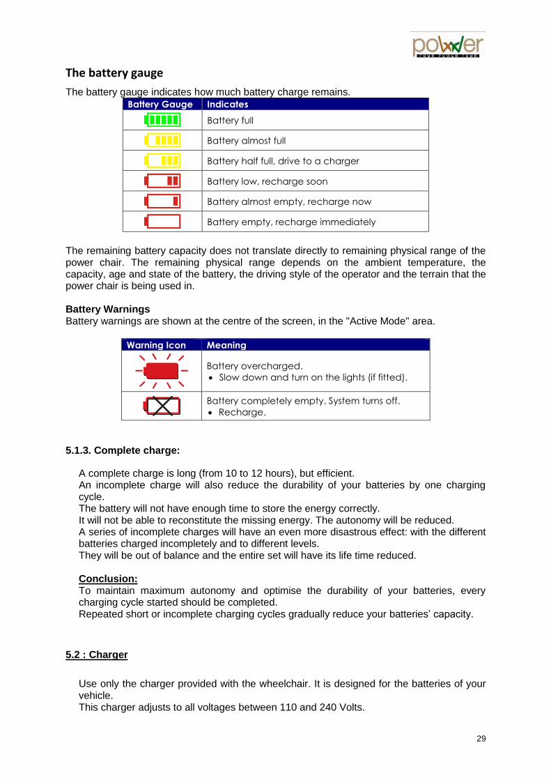
The battery gauge
The battery gauge indicates how much battery charge remains.
Battery Gauge Indicates
Battery full
Battery almost full
Battery half full, drive to a charger
Battery low, recharge soon
Battery almost empty, recharge now
Battery empty, recharge immediately
The remaining battery capacity does not translate directly to remaining physical range of the power chair. The remaining physical range depends on the ambient temperature, the capacity, age and state of the battery, the driving style of the operator and the terrain that the power chair is being used in. Battery Warnings Battery warnings are shown at the centre of the screen, in the "Active Mode" area.
Warning Icon Meaning
Battery overcharged.
Slow down and turn on the lights (if fitted).
Battery completely empty. System turns off.
Recharge.
5.1.3. Complete charge:
A complete charge is long (from 10 to 12 hours), but efficient. An incomplete charge will also reduce the durability of your batteries by one charging cycle. The battery will not have enough time to store the energy correctly. It will not be able to reconstitute the missing energy. The autonomy will be reduced. A series of incomplete charges will have an even more disastrous effect: with the different batteries charged incompletely and to different levels. They will be out of balance and the entire set will have its life time reduced. Conclusion: To maintain maximum autonomy and optimise the durability of your batteries, every charging cycle started should be completed. Repeated short or incomplete charging cycles gradually reduce your batteries’ capacity.
5.2 : Charger
Use only the charger provided with the wheelchair. It is designed for the batteries of your vehicle. This charger adjusts to all voltages between 110 and 240 Volts.
30
It initiates a programmed charge phase and disconnects automatically at the end of the cycle to prevent damage to the batteries. The charger should to be placed on a flat surface and protected from humidity. For your own safety it is imperative that you read and observe the following intructions before using the charger. 1) Before charging the batteries, switch off the wheelchair. 2) Connect the charging cable to the wheelchair, than connect the charger to the power socket. 3) Once the charge is completed, first unplug from the power socket, than disconnect the charging cable from the wheelchair.
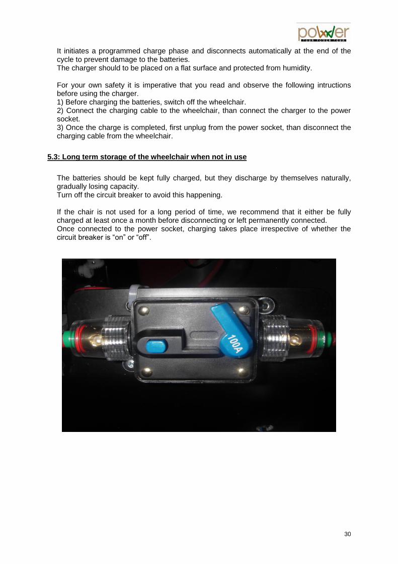
5.3: Long term storage of the wheelchair when not in use
The batteries should be kept fully charged, but they discharge by themselves naturally, gradually losing capacity. Turn off the circuit breaker to avoid this happening. If the chair is not used for a long period of time, we recommend that it either be fully charged at least once a month before disconnecting or left permanently connected. Once connected to the power socket, charging takes place irrespective of whether the circuit breaker is “on” or “off”.

31
5.4 – Wheels and motors
5.4.1 - Engaging and disengaging the motors
The motors of your chair can:
- be disengaged to allow the wheelchair to be propelled in freewheel mode - or be engaged for electromotor mode
The levers are located on the side of the motors away from the wheel.
Engaging: (to be repeated for each motor) Unlock the lever by shifting sideways then downwards. The wheels are now connected to the motors for driving. Disengaging: (to be repeated for each motor) Unlock the lever by shifting sideways then upwards. The chair can now be pushed in freewheel mode.
Engagement
lever

32
5.4.2 - Changing a wheel
Before handling, the electronic controls should be switched off. Completely empty the tyre of air using the valve. If you remove a wheel which is still inflated, the air will release the wheel rims from the motor with force. This can cause serious injury. Because blue Locktite was applied to the screws at assembly use a hair dryer to soften it before unscrewing the 6 nuts. Then remove the 6 washers and remove the wheel. To put back the wheel back on, perform the steps in reverse order making sure the valve is positioned on the outer side of the chair. Use blue Locktite or a similar product on the screws before tightening! After tightening the nuts, you can re-inflate the tyres. The recommended pressure is about 1 bar per tyre. Note : Grip tires use soft rubber with a short life expectancy (about 500 to 800 km for front and between 1 000 et 1 200 km for rear). For a intensive use in mix conditions (road and path), we recommend the use of mix tires which will provide 2 or 3 times longer life expectancy.
Nuts + washers
Valve

33
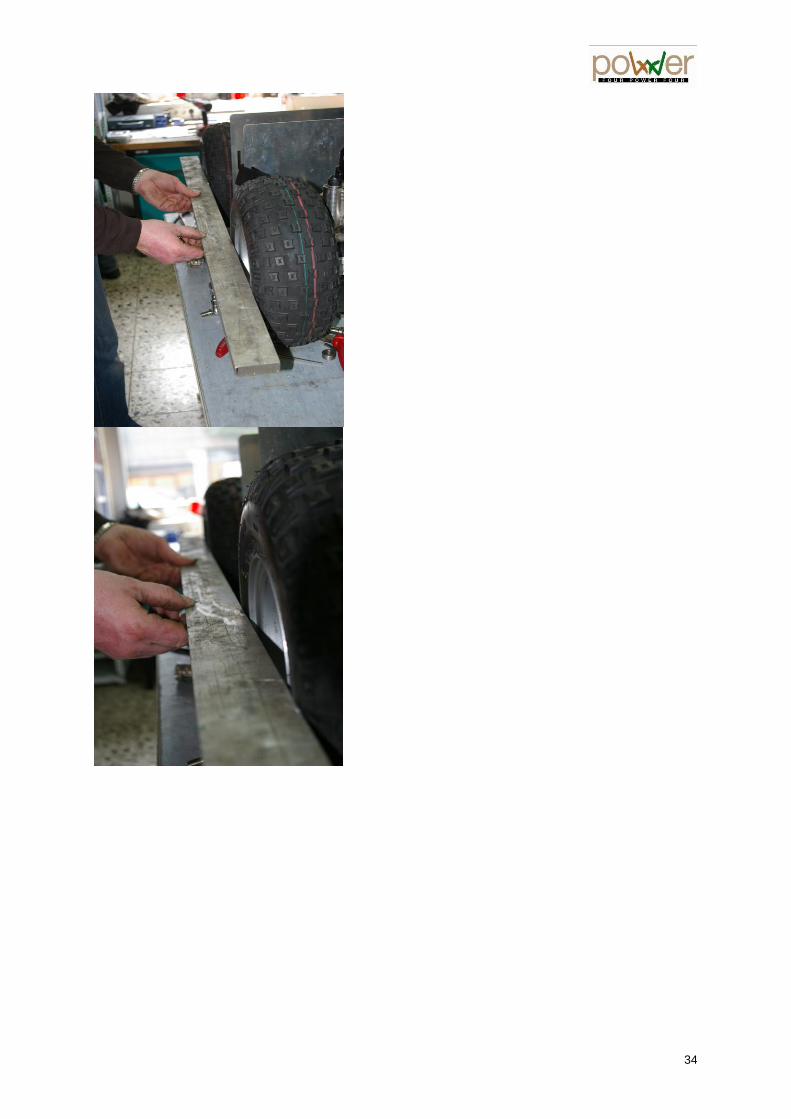
5.4.3 - Setting the parallelism For a pleasant driving of the wheelchair and normal u se of the tires, a proper wheel alignment must periodically be ensured. Ideally it should carry out the operation two operators: one place alignment lateral bars while the other will make the adjustment of the steering arm. The parallelism is set as follows: • 1 - Raise the chair so that the wheels are off the ground.
• 2 - Remove the covers. • 3 - Loosen the 2 nuts located on either side of the steering arm. • 4 - Repeat for each of the four wheels. • 5 - Place the alignment bar in contact with the sides of the 2 front and rear tires. • 6 - Do the same on the other side of the chair. • 7 - Connect both alignment bars together, if possible at the level of the wheel hub. • 8 - With the help of the steering bar adjustment threads, make the paralleling of two alignment bars. • 9 - 2 alignment bars being parallel and in contact with the sidewalls of the tires, put a drop of Loctite 243 BLUE, then tighten the nuts of steering arms making sure to maintain the parallelism of the alignment rules.
Ball joint Steering arm
Nut &
lock nut
34

5.4.4 - Actuator potentiometer adjustment • 1 - Make sure that the wheel alignment has been checked and perfect. • 2 - Move the chair forward to ensure that the 4 wheels are perfectly straight and aligned. • 3 - Remove the black cover of the back batteries. • 4 - Bring an Ohm meter (capacity 20kohm) • 5 - Take the measurement at the son 3 and 6 of the SLM plug (Power Light Module). • 6 - The value to be obtained is 5.4 KOhm. • 7 - When the actual value differs from 5.4 kOhm, remove the rectangular cover. • 8 - Shift the screw securing the small gear of the potentiometer, taking the precaution of not unscrew completely. • 9 - Leave the peaks of the Ohm meter in contact with the son 3 and 6 of the SLM card to read the value in ohms. • 10 - Equipped with a flathead screwdriver. • 11 - Screw or unscrew the knob until the value of 5.4 kOhm.

36
5.5 - Cleaning
Regular cleaning of your electric wheelchair is highly recommended both for hygienic reasons and for its proper operation. Painted parts : clean with soapy water. Saddlery : use a soft and slightly damp cloth. WARNING ! After use in rain, dry the chair carefully with a soft cloth. WARNING ! Do not use rough or corrosive products, or high-pressure hoses which damaged the electronics and degrease the ball bearings. Use steam cleaner with added disinfectant. WARNING ! Sand and seawater can damage ball bearings and certain joints. WARNING ! The electric parts must not come into contact with water.
5.6 - Error codes on status display
Different error messages can be displayed. First check the electronics system is working. If the status display does not come “on”, check:
- the electronics system is “On” - all cables are correctly connected - the batteries are not flat - the fuse has not blown.
Having checked the above, count the number of blinks and refer to the DX2 user manual. The joystick, the leds and the sound signal allow you to diagnose the problem(s).
3 Error Code

37
Chapter VI : Transport
6.1 – Anchorage point
This wheelchair is equipped with anchoring systems (see photos below) enabling it to be secured in a specially equipped vehicle (a system of rails and safety straps front and rear keeping the wheelchair safely secured). WARNING ! It is essential the user be secured by a system fitted to the vehicle. If the user remains seated in the wheelchair during transport, the safety belt of the motor vehicle must be used. The wheelchair safety belt on its own is not approved for transport in a motor vehicle. WARNING ! Check the wheelchair is safely strapped down. If the wheelchair is not safely strapped down, there is a risk of it coming loose and thus causing injury to the passenger(s) and damaging the equipment.
Front
anchoring
Rear
anchoring
38
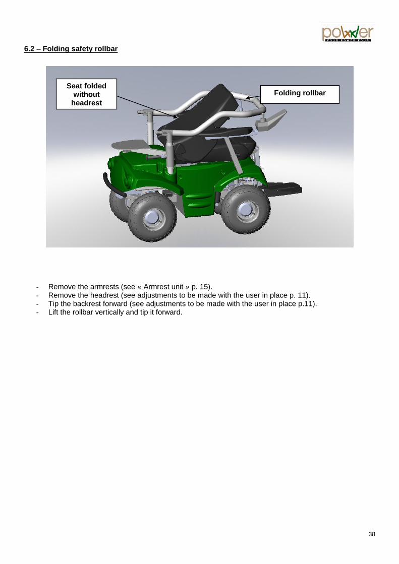
6.2 – Folding safety rollbar
- Remove the armrests (see « Armrest unit » p. 15). - Remove the headrest (see adjustments to be made with the user in place p. 11). - Tip the backrest forward (see adjustments to be made with the user in place p.11). - Lift the rollbar vertically and tip it forward.
Folding rollbar Seat folded
without headrest

39
Chapter VII : P4 COUNTRYv2 specifications data
1 - Specifications particular to the wheelchair
Frame : Rigid, stainless and aluminium steel. Seat : Adjustable for seat depth, backrest tilt and backrest width. Saddlery : Recaro “Expert M” black Dinamica interior and imitation black leather exterior. Armrests : Foldaway. Footrest : Adjustable for height, depth and tilt, pneumatic jack assisted. Brakes : Electromagnetic, in the wheel motors. Maximum tilt seat : 20° Maximum tilt backrest : 180° / seat (without rear suitcase or rollbar) Maximum tilt footrest : 56° / vertical Tyres : 145/70 - 6 with innertube Tyre pressure : 0,8 to 1 bar
2 - Driving system specifications
4 permanent steering and propelling wheels Maximum user weight : 120 kg (265 lbs) Maximum upward slope : 20% Maximum downward slope : 30% Maximum lateral slope : 20% Floor clearance : 15 cm (6 inches) Maximum obstacle clearance : 15 cm. (6 inches) Operating temperature : approx. -20°C/+50°C Top speed : 11 km/h (7 mph) Steering lock radius (turning circle US) 1.063m (42 inches)
3 - Electrical circuit specifications
Electrically driven by four 250 watt motors Motor voltage : 24 volts Batteries : according version - AGM no-maintenance watertight 12 volts / 110Ah
- AGM no-maintenance watertight 8 volts / 200Ah - Lithium 160 Ah
Nominal operating voltage : 24 volts Lighting voltage : 24 volts Recommended charger : 24 volts / 15 or 25 amp
4 - Dimensions and weight
Total wheelchair weight empty and without batteries: 140 kg (320 lbs) Topcase capacity : 39 litres Maximum topcase load : 3 kg (6.6 lbs) Wheelchair length plates open (min / max) : 145 cm / 210 cm (57”/ 83”) Wheelchair length plates closed (min / max) : 115 cm / 180 cm (46”/ 71”) Wheelchair width (min / max) : 68 cm / 79 cm (26“/ 31“) Wheelchair height rollbar and headrest folded : 0.95 cm (37.40 inches) Wheelchair height without rollbar, without headrest : 120 cm (47.25 inches) Wheelchair height with rollbar : 151 cm (59.45 inches)

40
7.5 – Electric wiring
Ensure this assembly diagram is followed as otherwise use of the wheelchair is dangerous. Special care should be taken when charging the batteries. They must be correctly placed to obtain 24 volts from the three 8-volt batteries.

41
Chapter VIII : Standards and Certification
8.1 - Electromagnetic compatibility
This wheelchair has been tested in accordance with European and international standards. However in certain cases there may be a risk of malfunctioning due to electromagnetic fields. WARNING! Electric and electronic devices (TV, radio, industrial machine, electronic medical appliances, mobile phone …) may cause electromagnetic interference likely to affect the correct operation of the electric wheelchair. They should be avoided. WARNING! Allow for the risk of interference due to electromagnetic radiation if electrical parts or accessories are added to the electric wheelchair.
8.2 - EC Standard tested
Compliance of the device with Annex 1 of EEC 93/42 directive is certified by the EC label.
8.3 - Waste management
Warning ! This product has been supplied by an environmentally-sensitive manufacturer who complies with the 2002/96/EC directive concerning disposal of electric and electronic equipment (WEEE). This product may contain substances harmful to the environment if you dispose of them in places not designed for this as stipulated by the legislation. The barred dustbin symbol is stamped on this product so as to encourage you to recycle whenever possible. Protect the environment and recycle this product in a recycling centre at the end of its product life.

42
P4 COUNTRY CERTIFICATE OF GUARANTEE
TO BE KEPT BY THE USER
Wheelchair serial number N° : ...........................................…………...
The off-road wheelchair you have just acquired is guaranteed, as from delivery, in the following way :
- TWO years against any manufacturing defect, excluding the tyres and saddlery which are not covered by the guarantee.
- One year against any manufacturing defect in the electrical parts (except batteries – no guarantee).
Extent of the Guarantee: The guarantee includes total cover of labour and replacement for parts found to be defective upon examination by the manufacturer. Conditions of exercise of the Guarantee: The guarantee provided only applies if the materials have been supplied by a Lifestand-approved dealer and used in normal operating conditions. The guarantee does not apply to incidents stemming from:
- normal wear and tear ; - abnormal use ; - neglect in maintenance ; - modifications without the manufacturer’s supervision.
Similarly, it does not apply to metal elements which may have been modified by whomsoever after delivery, either by transformation of initial parts, or by installation of new non-original parts. Exchanges and repairs of parts within the framework of this guarantee do not result in extension of this guarantee. The liability of the manufacturer being expressly limited, as specified above, the company cannot be held liable for any loss, damage or claim from third parties having its origin in any defect covered by the guarantee. In case of return to works, shipping outward and return is at the customer’s expense.

43
P4 COUNTRY SERVICING LOGBOOK
Yearly maintenance of your chair by your dealer will allow you to preserve optimum performance levels. This maintenance guarantees high safety levels.
Delivery note number :
Chair identification number :
Dealer’s name and address :
Purchase date :
Joystick number :
Power module numbers :

44
Year #1
Intervention and maintenance report : …………………………………………………………………………………………………………………………………………………………………………………………………………………………………………………………………………………………………………………………………………………………………………………………………………………………………………………………………………………………………………………………………………………………………………………………………………………………………………………………………………………………………………………………………………………………………………………………… Technician : Date et signature : ………………………………… ……………………………………
Year #2
Intervention and maintenance report : …………………………………………………………………………………………………………………………………………………………………………………………………………………………………………………………………………………………………………………………………………………………………………………………………………………………………………………………………………………………………………………………………………………………………………………………………………………………………………………………………………………………………………………………………………………………………………………………… Technician : Date et signature : ………………………………… ……………………………………
Year #3
Intervention and maintenance report : …………………………………………………………………………………………………………………………………………………………………………………………………………………………………………………………………………………………………………………………………………………………………………………………………………………………………………………………………………………………………………………………………………………………………………………………………………………………………………………………………………………………………………………………………………………………………………………………… Technician : Date et signature : ………………………………… ……………………………………

45
Year #4
Intervention and maintenance report : …………………………………………………………………………………………………………………………………………………………………………………………………………………………………………………………………………………………………………………………………………………………………………………………………………………………………………………………………………………………………………………………………………………………………………………………………………………………………………………………………………………………………………………………………………………………………………………………… Technician : Date et signature : ………………………………… ……………………………………
Year #5
Intervention and maintenance report : ……………………………………………………………………………………………………………………………………………………………………………………………………………………………………………………………………………………………………………………………………………………………………………………………………………………………………………………………………………………………………………………………………………………………………………………………………………………………………………………………………………………………………………………………………………………………………………………………………………………………………………………………………………………………………………………………………………………………………………………………………………………… Technician : Date et signature : ………………………………… ……………………………………
Year #6
Intervention and maintenance report : …………………………………………………………………………………………………………………………………………………………………………………………………………………………………………………………………………………………………………………………………………………………………………………………………………………………………………………………………………………………………………………………………………………………………………………………………………………………………………………………………………………………………………………………………………………………………………………………… Technician : Date et signature : ………………………………… ……………………………………

46
Year #7
Intervention and maintenance report : …………………………………………………………………………………………………………………………………………………………………………………………………………………………………………………………………………………………………………………………………………………………………………………………………………………………………………………………………………………………………………………………………………………………………………………………………………………………………………………………………………………………………………………………………………………………………………………………… Technician : Date et signature : ………………………………… ……………………………………
Year #8
Intervention and maintenance report : …………………………………………………………………………………………………………………………………………………………………………………………………………………………………………………………………………………………………………………………………………………………………………………………………………………………………………………………………………………………………………………………………………………………………………………………………………………………………………………………………………………………………………………………………………………………………………………………… Technician : Date et signature : ………………………………… ……………………………………
Year #9
Intervention and maintenance report : …………………………………………………………………………………………………………………………………………………………………………………………………………………………………………………………………………………………………………………………………………………………………………………………………………………………………………………………………………………………………………………………………………………………………………………………………………………………………………………………………………………………………………………………………………………………………………………………… Technician : Date et signature : ………………………………… ……………………………………

47
Year #10
Intervention and maintenance report : …………………………………………………………………………………………………………………………………………………………………………………………………………………………………………………………………………………………………………………………………………………………………………………………………………………………………………………………………………………………………………………………………………………………………………………………………………………………………………………………………………………………………………………………………………………………………………………………… Technician : Date et signature : ………………………………… ……………………………………
Year #11
Intervention and maintenance report : …………………………………………………………………………………………………………………………………………………………………………………………………………………………………………………………………………………………………………………………………………………………………………………………………………………………………………………………………………………………………………………………………………………………………………………………………………………………………………………………………………………………………………………………………………………………………………………………… Technician : Date et signature : ………………………………… ……………………………………
Year #12
Intervention and maintenance report : …………………………………………………………………………………………………………………………………………………………………………………………………………………………………………………………………………………………………………………………………………………………………………………………………………………………………………………………………………………………………………………………………………………………………………………………………………………………………………………………………………………………………………………………………………………………………………………………… Technician : Date et signature : ………………………………… ……………………………………

48
on
31/0
3/2
017
4 poWer 4 Rue Baron de Castro 16
B-1040 Brussels Belgium
Tél. +32 (0) 2735 1101 – Fax +33 (0) 2735 2202 www.4power4.com
e-mail : [email protected]