P225 PLATFORM HOIST INSTRUCTIONS - … Hoist/Platform... · P225 PLATFORM HOIST INSTRUCTIONS ......
24
P225 PLATFORM HOIST INSTRUCTIONS REIMANN & GEORGER CORPORATION HOISTING PRODUCTS BUFFALO, NY P/N 6102083 07/30/13
Transcript of P225 PLATFORM HOIST INSTRUCTIONS - … Hoist/Platform... · P225 PLATFORM HOIST INSTRUCTIONS ......
P225 PLATFORM HOIST
INSTRUCTIONS REIMANN & GEORGER CORPORATION HOISTING PRODUCTS BUFFALO, NY P/N 6102083 07/30/13
TABLE OF CONTENTS CHAPTER DESCRIPTION PAGE 1 SAFETY ....................................................................................................................................... 1
1.1 Introduction ................................................................................................................................... 1 1.2 Safety Definitions .......................................................................................................................... 1 1.3 Platform Hoist Safety Labels ......................................................................................................... 1 1.4 Platform Hoist Safety Rules ........................................................................................................... 1
2 SPECIFICATIONS ..................................................................................................................... 3 2.1 Platform Hoist Specifications ........................................................................................................ 3 2.2 Complete System Specifications .................................................................................................... 3 2.3 Nameplate and Serial Number Tag ................................................................................................ 3
3 INSTALLATION AND SETUP ................................................................................................. 4 3.1 Prior to Setup ................................................................................................................................. 4 3.2 Completing the Platform Assembly ............................................................................................... 4 3.3 Mounting the Platform on the Track .............................................................................................. 6 3.4 Assembling the Track Sections ...................................................................................................... 6 3.5 Mounting the Top Bracket ............................................................................................................. 6 3.6 Raising the Track ........................................................................................................................... 7 3.6.1 Procedure A ................................................................................................................................... 7 3.6.2 Procedure B ................................................................................................................................... 7 3.7 Reeving the hoist ........................................................................................................................... 8 3.8 Installing Track Support ................................................................................................................ 8
4 OPERATION ............................................................................................................................. 10 4.1 Before Operating the Platform Hoist ........................................................................................... 10 4.2 Raising and Lowering the Load ................................................................................................... 10 4.3 Preparing Platform Hoist for Shutdown ....................................................................................... 11
5 DISASSEMBLY ......................................................................................................................... 12 5.1 Prior to Disassembly .................................................................................................................... 12 5.2 Removing Track Support ............................................................................................................. 12 5.3 Lower the Track ........................................................................................................................... 12 5.4 Disassembling the Track Sections ............................................................................................... 13
6 INSPECTION AND MAINTENANCE ................................................................................... 14 6.1 General Maintenance Rules ......................................................................................................... 14 6.2 Initial Inspection .......................................................................................................................... 14 6.3 Daily Inspection ........................................................................................................................... 14 6.4 Safety Hooks ................................................................................................................................ 15 6.5 Wire Rope Inspection Procedure ................................................................................................. 15 7 TROUBLESHOOTING ............................................................................................................ 16 8 PARTS LIST .............................................................................................................................. 17 RGC HOISTING PRODUCTS PHONE: (716) 895-1156
LIST OF FIGURES FIGURE DESCRIPTION PAGE 2-1 Platform Hoist Product Nameplate ................................................................................................ 3 3-1 Platform Wheel Placement Guide .................................................................................................. 5 3-2 Platform Brace Assembly .............................................................................................................. 5 3-3 Bottom Track Section .................................................................................................................... 6 3-4 Track Support Assembly ............................................................................................................... 9 6-1 Wire Rope Components ............................................................................................................... 15 8-1 Platform Hoist Assembly Drawing .............................................................................................. 18
LIST OF TABLES TABLE TITLE PAGE 3-1 Track Support Location Requirements .......................................................................................... 8
RGC HOISTING PRODUCTS PHONE: (716) 895-1156
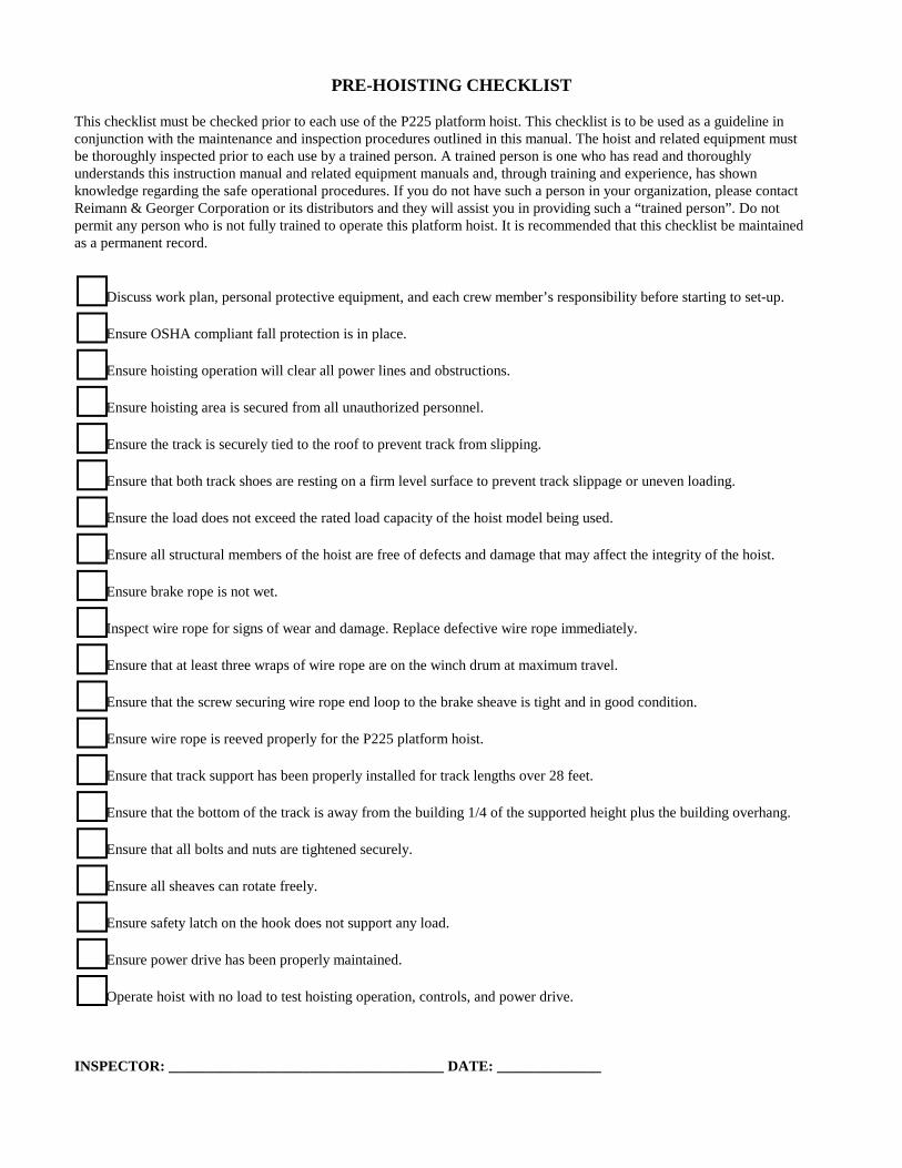
PRE-HOISTING CHECKLIST This checklist must be checked prior to each use of the P225 platform hoist. This checklist is to be used as a guideline in conjunction with the maintenance and inspection procedures outlined in this manual. The hoist and related equipment must be thoroughly inspected prior to each use by a trained person. A trained person is one who has read and thoroughly understands this instruction manual and related equipment manuals and, through training and experience, has shown knowledge regarding the safe operational procedures. If you do not have such a person in your organization, please contact Reimann & Georger Corporation or its distributors and they will assist you in providing such a “trained person”. Do not permit any person who is not fully trained to operate this platform hoist. It is recommended that this checklist be maintained as a permanent record.
Discuss work plan, personal protective equipment, and each crew member’s responsibility before starting to set-up.
Ensure OSHA compliant fall protection is in place.
Ensure hoisting operation will clear all power lines and obstructions.
Ensure hoisting area is secured from all unauthorized personnel.
Ensure the track is securely tied to the roof to prevent track from slipping.
Ensure that both track shoes are resting on a firm level surface to prevent track slippage or uneven loading.
Ensure the load does not exceed the rated load capacity of the hoist model being used.
Ensure all structural members of the hoist are free of defects and damage that may affect the integrity of the hoist.
Ensure brake rope is not wet.
Inspect wire rope for signs of wear and damage. Replace defective wire rope immediately.
Ensure that at least three wraps of wire rope are on the winch drum at maximum travel.
Ensure that the screw securing wire rope end loop to the brake sheave is tight and in good condition.
Ensure wire rope is reeved properly for the P225 platform hoist.
Ensure that track support has been properly installed for track lengths over 28 feet.
Ensure that the bottom of the track is away from the building 1/4 of the supported height plus the building overhang.
Ensure that all bolts and nuts are tightened securely.
Ensure all sheaves can rotate freely.
Ensure safety latch on the hook does not support any load.
Ensure power drive has been properly maintained.
Operate hoist with no load to test hoisting operation, controls, and power drive. INSPECTOR: _____________________________________ DATE: ______________
1 SAFETY
1.1 INTRODUCTION Your Reimann & Georger Corporation P225 Platform Hoist has been engineered to provide lifting performance, long term economics and safety advantages that no other type can match. However, even a well-designed and well-built hoist can malfunction or become hazardous in the hands of an inexperienced and/or untrained user. Therefore, read this manual, and related equipment manuals thoroughly before operating your hoist to provide maximum safety for all operating personnel, and to get the maximum benefit from your equipment. 1.2 SAFETY DEFINITIONS A safety message alerts you to potential hazards that could injure you or others or cause property damage. The safety messages or signal words for product safety signs are DANGER, WARNING, and CAUTION. Each safety message is preceded by a safety alert symbol and is defined as follows: DANGER: Indicates an imminently hazardous situation which, if not avoided, will cause death or serious injury. This safety message is limited to the most extreme situations. WARNING: Indicates a potentially hazardous situation which, if not avoided, could result in death or serious injury. CAUTION: Indicates a potentially hazardous situation which, if not avoided, may result in minor or moderate injury. It may also be used to alert against unsafe practices and property-damage-only accidents. 1.3 PLATFORM HOIST SAFETY LABELS These labels warn you of potential hazards that could cause injury. Read them carefully. If a label comes off or becomes illegible, contact Reimann & Georger Corporation for a free replacement. 1.4 HOIST SAFETY RULES 1. Operators must be trained before operating this hoist. A trained person is one who has read and thoroughly
understands this instruction manual and related equipment manuals and, through training and experience, has shown knowledge regarding the safe operational procedures.
2. Prior to setting up the hoist there must be a plan of action outlining the work to be accomplished, individual
responsibilities, personal protective equipment, and method of communication. 3. All personnel shall be protected by OSHA compliant fall protection where applicable. 4. Never use the hoist structure to anchor life lines, worker’s harnesses or other attachments. 5. Always use safety footwear, safety glasses, and head protection devices. 6. A good line of communication must be maintained between the hoist operator and the roof crew. 7. Hoisting area is to be kept clear of unauthorized personnel at all times. Place barricades or secure the area in such a
manner that if there were an equipment failure, no personnel would be injured. 8. Hoisting area is to be clear of power lines. Consult power company before you work near power lines. 9. Follow the Pre-Hoisting Checklist before operating. 10. Wear heavy leather gloves when handling wire rope. 11. Secure load before lifting.
1
12. Do not remove material from the platform until it has stopped completely. 13. Keep out from under a raised load. 14. Never stand in-line with the raising or lowering of the platform at either the top or bottom of the hoist track. 15. Never hoist over an open doorway. 16. Never exceed the Rated Load Capacity of 200 pounds for the P225 hoist. The Rated Load Capacity is the maximum
load that should ever be applied to the hoist. 17. Avoid sudden stops and shock loads. 18. No person shall be allowed to ride on the hoist. 19. NEVER climb the track; use a ladder. 20. Check the hoist periodically during operation. Know how to stop the power drive quickly in case of emergency. 21. Do not attempt to make adjustments while the hoist is being operated. 22. If the engine or motor fails during operation, release control levers to prevent load from falling. 23. Keep all body parts clear of moving parts. 24. Do not operate hoist when brake rope is wet. 25. Do not operate hoist when under the influence of drugs, alcohol, or medication. 26. At end of operation, the hoist should be secured to prevent unauthorized use. Never assume you will find the hoist in
the same condition in which you left it. 27. Do not weld or otherwise modify the hoist. Such alterations may weaken the structural integrity of the hoist. 28. Only trained personnel are authorized to do repairs.
2
2 SPECIFICATIONS 2.1 HOIST SPECIFICATIONS MODEL P225
Load capacity 200 lbs. Lift speed 220 fpm Platform size 17 in. x 18 in. Track (3 3/4” side rail) 17 in. width Wire rope (both models) 5/32-in. diameter, 7 x 19 galvanized aircraft wire rope Note that platform speeds and capacities are average and are based on 5/32 inch wire rope diameter. As wire rope builds up on drum, lifting speed increases and lifting capacity decreases in direct proportion to drum diameter. 2.2 COMPLETE SYSTEM SPECIFICATIONS 16 foot: Includes Power Drive, P225 Platform assembly, 16-foot aluminum Track with shoes. 28 foot: Includes Power Drive, P225 Platform assembly, 16-foot aluminum Track with shoes, additional 8 foot and 4 foot
Track sections with splice plates. 44 foot: Includes Power Drive, P225 Platform assembly, 16 foot aluminum Track with shoes, additional 16 foot, 8 foot,
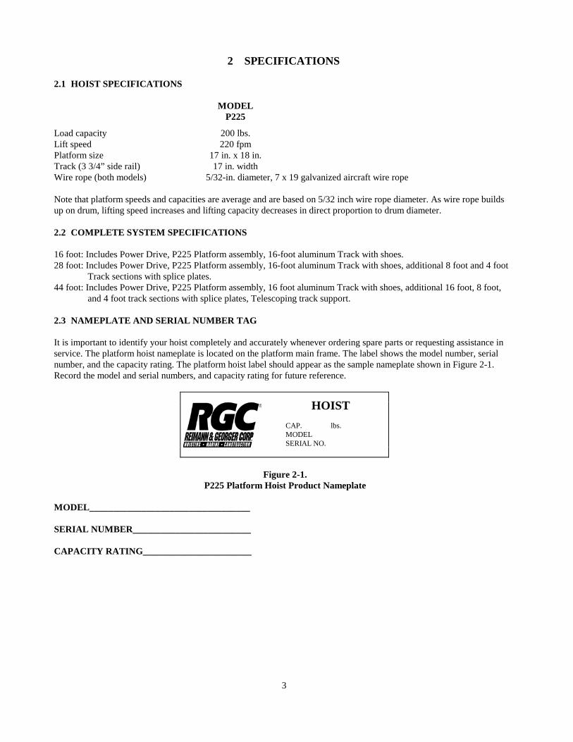
and 4 foot track sections with splice plates, Telescoping track support. 2.3 NAMEPLATE AND SERIAL NUMBER TAG It is important to identify your hoist completely and accurately whenever ordering spare parts or requesting assistance in service. The platform hoist nameplate is located on the platform main frame. The label shows the model number, serial number, and the capacity rating. The platform hoist label should appear as the sample nameplate shown in Figure 2-1. Record the model and serial numbers, and capacity rating for future reference.
Figure 2-1.
P225 Platform Hoist Product Nameplate MODEL__________________________________ SERIAL NUMBER_________________________ CAPACITY RATING_______________________
HOIST CAP. lbs. MODEL SERIAL NO.
3
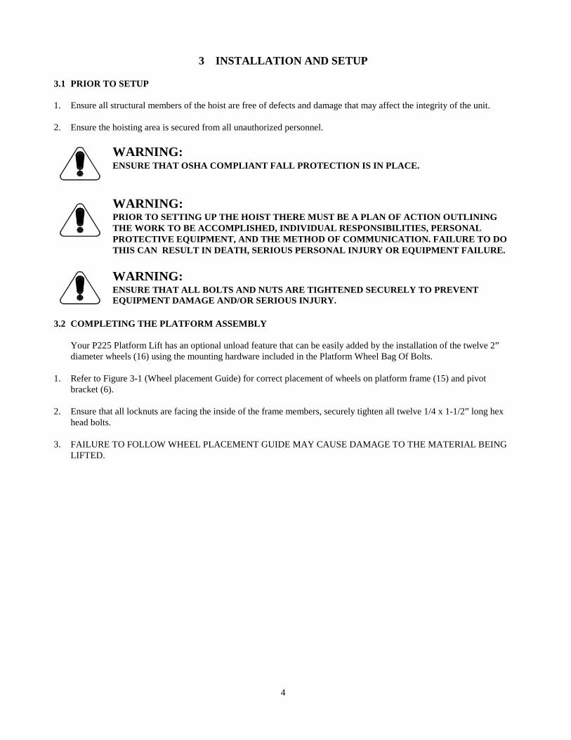
3 INSTALLATION AND SETUP 3.1 PRIOR TO SETUP 1. Ensure all structural members of the hoist are free of defects and damage that may affect the integrity of the unit. 2. Ensure the hoisting area is secured from all unauthorized personnel.
WARNING: ENSURE THAT OSHA COMPLIANT FALL PROTECTION IS IN PLACE.
WARNING:PRIOR TO SETTING UP THE HOIST THERE MUST BE A PLAN OF ACTION OUTLININGTHE WORK TO BE ACCOMPLISHED, INDIVIDUAL RESPONSIBILITIES, PERSONALPROTECTIVE EQUIPMENT, AND THE METHOD OF COMMUNICATION. FAILURE TO DOTHIS CAN RESULT IN DEATH, SERIOUS PERSONAL INJURY OR EQUIPMENT FAILURE.
WARNING: ENSURE THAT ALL BOLTS AND NUTS ARE TIGHTENED SECURELY TO PREVENT EQUIPMENT DAMAGE AND/OR SERIOUS INJURY.
3.2 COMPLETING THE PLATFORM ASSEMBLY
Your P225 Platform Lift has an optional unload feature that can be easily added by the installation of the twelve 2” diameter wheels (16) using the mounting hardware included in the Platform Wheel Bag Of Bolts.
1. Refer to Figure 3-1 (Wheel placement Guide) for correct placement of wheels on platform frame (15) and pivot
bracket (6). 2. Ensure that all locknuts are facing the inside of the frame members, securely tighten all twelve 1/4 x 1-1/2” long hex
head bolts. 3. FAILURE TO FOLLOW WHEEL PLACEMENT GUIDE MAY CAUSE DAMAGE TO THE MATERIAL BEING
LIFTED.
4
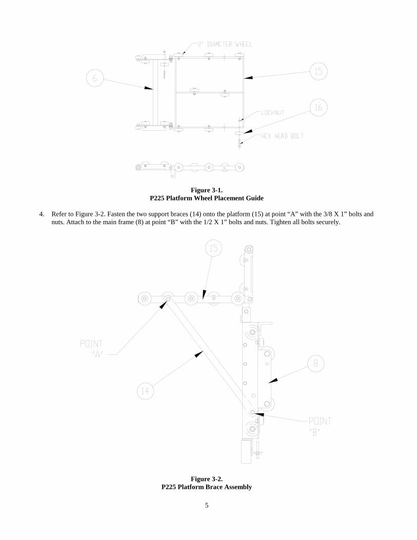
Figure 3-1. P225 Platform Wheel Placement Guide
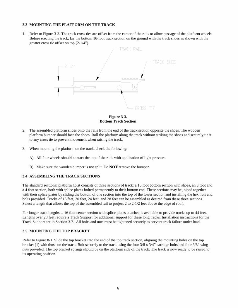
4. Refer to Figure 3-2. Fasten the two support braces (14) onto the platform (15) at point “A” with the 3/8 X 1” bolts and
nuts. Attach to the main frame (8) at point “B” with the 1/2 X 1” bolts and nuts. Tighten all bolts securely.
Figure 3-2. P225 Platform Brace Assembly
5
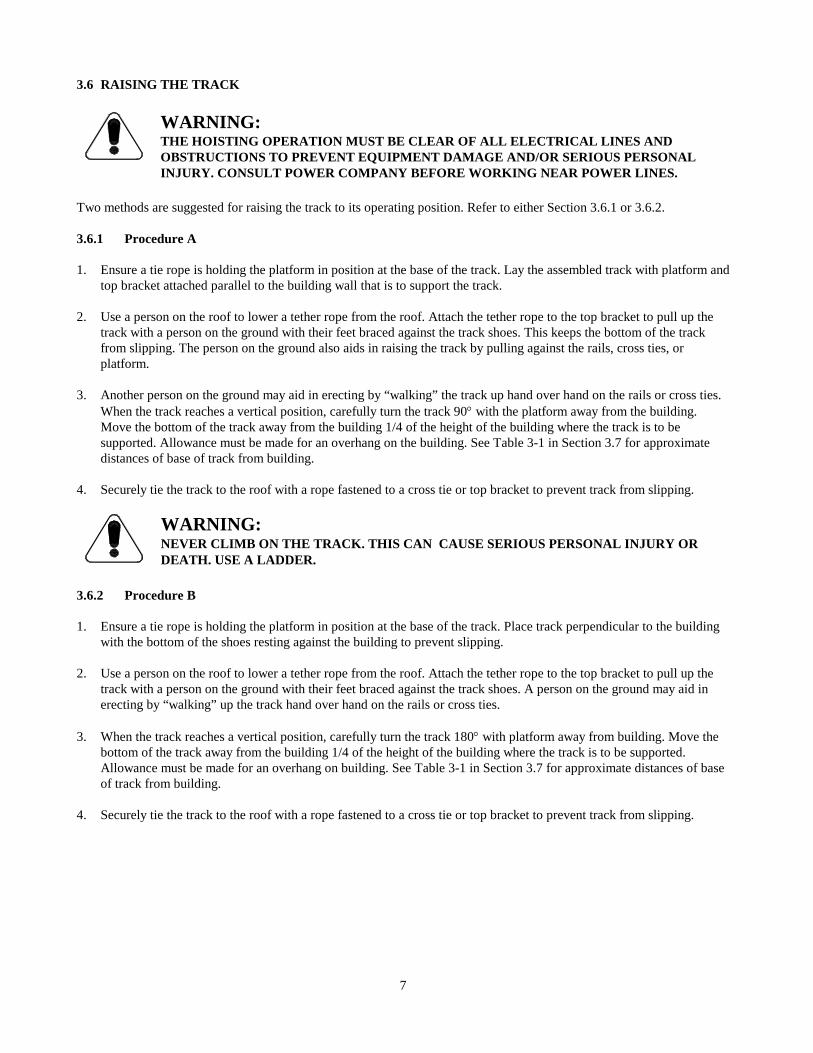
3.3 MOUNTING THE PLATFORM ON THE TRACK 1. Refer to Figure 3-3. The track cross ties are offset from the center of the rails to allow passage of the platform wheels.
Before erecting the track, lay the bottom 16-foot track section on the ground with the track shoes as shown with the greater cross tie offset on top (2-1/4”).
Figure 3-3. Bottom Track Section
2. The assembled platform slides onto the rails from the end of the track section opposite the shoes. The wooden
platform bumper should face the shoes. Roll the platform along the track without striking the shoes and securely tie it to any cross tie to prevent movement when raising the track.
3. When mounting the platform on the track, check the following:
A) All four wheels should contact the top of the rails with application of light pressure.
B) Make sure the wooden bumper is not split. Do NOT remove the bumper. 3.4 ASSEMBLING THE TRACK SECTIONS The standard sectional platform hoist consists of three sections of track: a 16 foot bottom section with shoes, an 8 foot and a 4 foot section, both with splice plates bolted permanently to their bottom end. These sections may be joined together with their splice plates by sliding the bottom of one section into the top of the lower section and installing the hex nuts and bolts provided. Tracks of 16 feet, 20 feet, 24 feet, and 28 feet can be assembled as desired from these three sections. Select a length that allows the top of the assembled rail to project 2 to 2-1/2 feet above the edge of roof. For longer track lengths, a 16 foot center section with splice plates attached is available to provide tracks up to 44 feet. Lengths over 28 feet require a Track Support for additional support for these long tracks. Installation instructions for the Track Support are in Section 3.7. All bolts and nuts must be tightened securely to prevent track failure under load. 3.5 MOUNTING THE TOP BRACKET Refer to Figure 8-1. Slide the top bracket into the end of the top track section, aligning the mounting holes on the top bracket (1) with those on the track. Bolt securely to the track using the four 3/8 x 3/4” carriage bolts and four 3/8” wing nuts provided. The top bracket springs should be on the platform side of the track. The track is now ready to be raised to its operating position.
6
3.6 RAISING THE TRACK
WARNING:THE HOISTING OPERATION MUST BE CLEAR OF ALL ELECTRICAL LINES ANDOBSTRUCTIONS TO PREVENT EQUIPMENT DAMAGE AND/OR SERIOUS PERSONALINJURY. CONSULT POWER COMPANY BEFORE WORKING NEAR POWER LINES.
Two methods are suggested for raising the track to its operating position. Refer to either Section 3.6.1 or 3.6.2. 3.6.1 Procedure A 1. Ensure a tie rope is holding the platform in position at the base of the track. Lay the assembled track with platform and
top bracket attached parallel to the building wall that is to support the track. 2. Use a person on the roof to lower a tether rope from the roof. Attach the tether rope to the top bracket to pull up the
track with a person on the ground with their feet braced against the track shoes. This keeps the bottom of the track from slipping. The person on the ground also aids in raising the track by pulling against the rails, cross ties, or platform.
3. Another person on the ground may aid in erecting by “walking” the track up hand over hand on the rails or cross ties.
When the track reaches a vertical position, carefully turn the track 90° with the platform away from the building. Move the bottom of the track away from the building 1/4 of the height of the building where the track is to be supported. Allowance must be made for an overhang on the building. See Table 3-1 in Section 3.7 for approximate distances of base of track from building.
4. Securely tie the track to the roof with a rope fastened to a cross tie or top bracket to prevent track from slipping.
WARNING:NEVER CLIMB ON THE TRACK. THIS CAN CAUSE SERIOUS PERSONAL INJURY ORDEATH. USE A LADDER.
3.6.2 Procedure B 1. Ensure a tie rope is holding the platform in position at the base of the track. Place track perpendicular to the building
with the bottom of the shoes resting against the building to prevent slipping. 2. Use a person on the roof to lower a tether rope from the roof. Attach the tether rope to the top bracket to pull up the
track with a person on the ground with their feet braced against the track shoes. A person on the ground may aid in erecting by “walking” up the track hand over hand on the rails or cross ties.
3. When the track reaches a vertical position, carefully turn the track 180° with platform away from building. Move the
bottom of the track away from the building 1/4 of the height of the building where the track is to be supported. Allowance must be made for an overhang on building. See Table 3-1 in Section 3.7 for approximate distances of base of track from building.
4. Securely tie the track to the roof with a rope fastened to a cross tie or top bracket to prevent track from slipping.
7
3.7 REEVING THE HOIST 1. Before reeving the hoist, inspect the wire rope for wear and damage. Detailed inspection procedures are in Chapter 6.
WARNING:WEAR HEAVY LEATHER GLOVES WHEN HANDLING WIRE ROPE. INSUFFICIENT HANDPROTECTION WHEN HANDLING WIRE ROPE CAN CAUSE SERIOUS PERSONAL INJURY.
WARNING:USING DEFECTIVE WIRE ROPE CAN CAUSE EQUIPMENT DAMAGE, SERIOUSPERSONAL INJURY, OR DEATH.
2. To reeve the hoist, tie a tether rope, lowered from the roof, to the wire rope end and with the brake released, pull the
hoist wire rope to the roof on the underside of the track. Remove the tether rope. Reeve the wire rope through the sheave on the top bracket. Reattach the tether rope and pull the wire rope to the ground on the platform side of the track. Remove the tether rope and fasten wire rope to the hook provided on the platform main frame. This is single line operation. The winding drum must not have less than three turns of rope when the platform is at the lowest point of travel. Ensure that the sheaves rotate freely.
3. Remove the tie rope holding platform in position on the track.
WARNING:MAKE SURE THAT BOTH TRACK SHOES ARE RESTING ON A FIRM, LEVEL SURFACE.THIS PREVENTS TRACK SLIPPAGE OR UNEVEN LOADING OF TRACK WHICH CANCAUSE EQUIPMENT DAMAGE OR PERSONAL INJURY.
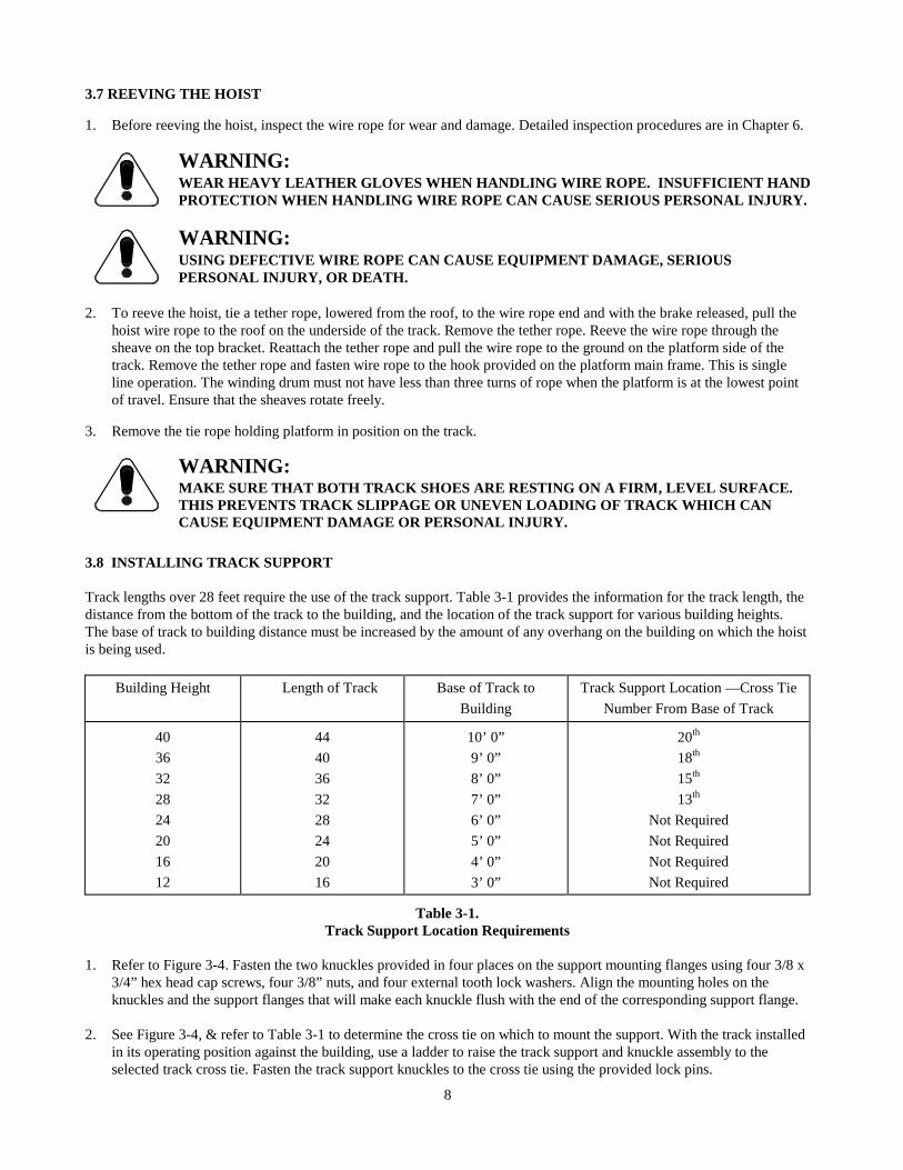
3.8 INSTALLING TRACK SUPPORT Track lengths over 28 feet require the use of the track support. Table 3-1 provides the information for the track length, the distance from the bottom of the track to the building, and the location of the track support for various building heights. The base of track to building distance must be increased by the amount of any overhang on the building on which the hoist is being used.
Building Height Length of Track Base of Track to Building
Track Support Location —Cross Tie Number From Base of Track
40 36 32 28 24 20 16 12
44 40 36 32 28 24 20 16
10’ 0” 9’ 0” 8’ 0” 7’ 0” 6’ 0” 5’ 0” 4’ 0” 3’ 0”
20th
18th 15th 13th
Not Required Not Required Not Required Not Required
Table 3-1. Track Support Location Requirements
1. Refer to Figure 3-4. Fasten the two knuckles provided in four places on the support mounting flanges using four 3/8 x
3/4” hex head cap screws, four 3/8” nuts, and four external tooth lock washers. Align the mounting holes on the knuckles and the support flanges that will make each knuckle flush with the end of the corresponding support flange.
2. See Figure 3-4, & refer to Table 3-1 to determine the cross tie on which to mount the support. With the track installed
in its operating position against the building, use a ladder to raise the track support and knuckle assembly to the selected track cross tie. Fasten the track support knuckles to the cross tie using the provided lock pins.
8
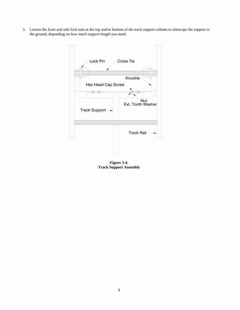
3. Loosen the front and side lock nuts at the top and/or bottom of the track support column to telescope the support to
the ground, depending on how much support length you need.
Figure 3-4.
Track Support Assembly
Track Support
Hex Head Cap Screw
Lock Pin
Knuckle
Cross Tie
Ext. Tooth WasherNut
Track Rail
9
4 OPERATION 4.1 BEFORE OPERATING THE HOIST
WARNING:A GOOD LINE OF COMMUNICATION MUST BE MAINTAINED BETWEEN THE HOISTOPERATOR AND THE ROOF CREW.
1. Only trained personnel shall operate this equipment. A trained person is one who has read and thoroughly understands
this instruction manual and related equipment manuals and, through training and experience, has shown knowledge regarding the safe operational procedures.
2. Obey all safety labels provided on your platform hoist and related equipment. These labels warn you of potential
hazards that can cause serious injury. If a label comes off or becomes hard to read, contact Reimann & Georger Corporation for a replacement.
3. Follow the Pre-hoisting Checklist in the front of this manual before operating. 4. Never use the hoist structure to anchor lifelines, worker harnesses, or other attachments. 5. Always use safety footwear, safety glasses, and head protection devices. 6. Before lifting, ensure the safety latch on the hook is not supporting any load. Never hoist over an open doorway.
WARNING:THE HOISTING OPERATION MUST BE CLEAR OF ALL ELECTRICAL LINES ANDOBSTRUCTIONS TO PREVENT EQUIPMENT DAMAGE AND/OR SERIOUS PERSONALINJURY. CONSULT POWER COMPANY BEFORE WORKING NEAR POWER LINES.
7. Hoisting area is to be kept clear of unauthorized personnel. Place barricades or secure the area in such a manner that if
there were an equipment failure, no personnel would be injured. 8. Inspect wire rope for damage, wear, or unraveling. Replace as necessary. 9. Check all hooks and sheaves. Replace as necessary. 4.2 RAISING AND LOWERING THE LOAD
WARNING:NEVER EXCEED THE RATED LOAD CAPACITY OF 200 POUNDS FOR THE P225 HOIST.THE RATED LOAD CAPACITY IS THE MAXIMUM LOAD THAT SHOULD EVER BEAPPLIED TO THE HOIST.
WARNING:SECURE THE LOAD BEFORE LIFTING.
1. Make a few “dry runs” (no load), to test hoisting operation, controls, and power drive.
WARNING:NEVER STAND IN-LINE WITH THE RAISING OR LOWERING OF THE PLATFORM ATEITHER THE TOP OR BOTTOM OF THE HOIST TRACK.
2. To raise the load, lift the clutch handle slowly with a smooth upward motion. This automatically tightens the drive belt
and releases the brake, permitting the platform to roll up the track.
10
3. When the platform reaches the top of the track, release the clutch handle. This action stops the platform and automatically applies the brake, which holds the load and platform. The load will now roll automatically off the platform if the optional wheel package has been installed on the platform frame.
WARNING:KEEP OUT FROM UNDER A RAISED LOAD.
WARNING:IF THE ENGINE OR MOTOR FAILS DURING OPERATION, RELEASE THE CONTROLHANDLES TO PREVENT LOAD FROM FALLING.
4. Do not allow the platform to jam against the spring stops on the top bracket. The drive belt may jam in the drum
sheave, preventing the lowering of the platform.
WARNING:DO NOT REMOVE MATERIAL FROM THE HOIST UNTIL IT HAS STOPPEDCOMPLETELY.
5. Lift the brake lever slowly to lower platform to the ground. Lowering speed for SAFE operation should not exceed
50 feet/minute. Continue to decelerate the platform as it nears the ground to prevent damage to platform or track. Do not allow the platform to strike the track shoes on reaching the bottom of the track. If necessary, extra downward pressure on the brake lever can be applied to stop the load.
WARNING:AVOID SUDDEN BRAKING WHEN HANDLING A LOAD.
6. Check the hoist periodically during operation. Do not attempt to make adjustments during operation.
WARNING:KEEP ALL BODY PARTS CLEAR OF MOVING PARTS.
4.3 PREPARING HOIST FOR SHUTDOWN At the end of operation, secure the equipment to prevent unauthorized use. Never assume you will find the equipment in the same condition that you left it. Proceed as follows: 1. Ensure that all lifting tension has been removed from the wire rope. 2. Shut off power drive and take necessary action to prevent its unauthorized use. 3. If the hoist is being permanently disassembled, at the end of a project for example, follow the detailed disassembly
procedures in Chapter 5.
11
5 DISASSEMBLY 5.1 PRIOR TO DISASSEMBLY 1. Before disassembling the hoist, read and follow all the safety rules of this manual. Failure to do this can lead to
equipment damage and/or serious personal injury. 2. Ensure that the platform is not supporting any load before proceeding. 3. Before dismantling, attach a tie rope to hold the platform in position at the base of the track. 4. Ensure the track is securely tied to the roof with a rope fastened to a cross tie or top bracket to prevent track from
slipping. 5. Check carefully for proximity of power lines or other overhead obstructions. 5.2 REMOVING TRACK SUPPORT 1. Using a ladder, loosen the front and side lock screws at the top and/or bottom of the track support column to telescope
the support into the flange. Re-tighten the lock screws.
WARNING:NEVER CLIMB ON THE TRACK FOR ANY REASON. THIS CAN CAUSE SERIOUSPERSONAL INJURY OR DEATH.
2. Remove the track support from the cross tie by unfastening the lock pins. 3. If the track support will be used on the same hoist model in future applications, the knuckles do not have to be
removed from the mounting flanges. 5.3 LOWERING THE TRACK 1. Unfasten the hoist wire rope from the hook provided on the platform. Pull the wire rope end through the sheave on the
top bracket to unreeve, attach a tether rope to the wire rope, and lower it to the ground.
WARNING:WEAR HEAVY LEATHER GLOVES WHEN HANDLING WIRE ROPE. INSUFFICIENT HANDPROTECTION WHEN HANDLING WIRE ROPE CAN CAUSE SERIOUS PERSONAL INJURY.
2. Tie a safety line at least 5 feet long to the wire rope end to prevent any accidental drawing of the operator’s hand into
the winch during rewinding. 3. Start the power drive and lift the clutch handle slowly to rewind wire rope. Ensure that the wire rope is rewinding
evenly on the drum. As the wire rope end approaches the drum, handle the wire rope only be the safety line. 4. When the wire rope end reaches the drum, release the clutch handle, shut off the power drive and remove the safety
line. Anchor the wire rope end on the drum with a light rope or tape. 5. Remove the operating handles from the power drive. Remove the lock pin from the cross tie lock and rotate the
handle to the right to loosen. Then remove the power drive from the track. 6. Attach a tether rope to the top bracket. Then untie the rope that fastens the track to the roof. 7. The person on the roof must lift up on the top bracket with the tether rope while a person on the ground moves the
bottom of the track towards the building. When the track reaches a vertical position, the person on the ground may either:
12
(a) turn the track 90º and have the roof person lower the track with the ground person bracing their feet against the
track shoes, or; (b) turn the track 180º, move the bottom of the track against the building and have the roof person lower the track
with the track shoes braced against the building.
In either case, the track must be turned to make the platform point upwards when the lowering operation is completed.
8. When the track has reached the ground, remove the tie rope holding the platform in position on the track. 5.4 DISASSEMBLING THE TRACK SECTIONS 1. Remove the top bracket from the end of the top track section. 2. Remove the installed hex nuts and bolts to separate each track section from the adjoining sections. Then roll the
platform down and off the track in the direction opposite the track shoes.
13
6 INSPECTION AND MAINTENANCE 6.1 GENERAL MAINTENANCE RULES 1. Proper maintenance of the hoist and related equipment consists of adhering to all the guidelines given in this chapter
and in the Pre-Hoisting Checklist in the front of this manual. Proper maintenance is required to maintain the system in good condition, which is defined as each part being free of rust or other corrosion, bends, breaks, or other defects.
2. Review and follow all the safety rules given in Chapter 1 before attempting any maintenance. 3. Only authorized personnel should be allowed in the maintenance area. Authorized personnel are the trained people as
defined below and their supervision. 4. Repairs must be made only by trained personnel. A trained person is one who has read and thoroughly understands
this instruction manual and related equipment manuals and, through training and experience, has shown knowledge regarding the safe operational procedures.
WARNING:WEAR HEAVY LEATHER GLOVES WHEN HANDLING WIRE ROPE. INSUFFICIENT HANDPROTECTION WHEN HANDLING WIRE ROPE CAN CAUSE SERIOUS PERSONAL INJURY.
5. Do not weld or otherwise modify the hoist. Such alterations may weaken the structural integrity of the hoist and
invalidate your warranty.
WARNING:DURING ANY ERECTION, MAINTENANCE, OR REPAIR PROCEDURES, DO NOT ATTEMPTANY HOISTING. THIS CAN CAUSE EQUIPMENT DAMAGE AND/OR SERIOUS PERSONALINJURY.
WARNING:EXCEPT FOR MAINTENANCE AND REPAIRS THAT CANNOT BE DONE OTHERWISE,SHUT DOWN AND LOCK OUT THE PRO DRIVE TO PREVENT ACCIDENTAL STARTUP.
WARNING:NEVER CLIMB THE TRACK TO DO MAINTENANCE. THIS CAN LEAD TO SERIOUSPERSONAL INJURY.
6.2 INITIAL INSPECTION Hoist erection and dismantling must be done by trained personnel only as defined in Section 6.1. Each time after setting up the hoist and before placing it in service, all parts of the structure, power drive, and other equipment must be thoroughly inspected by trained personnel as described in the remainder of this chapter. 6.3 DAILY INSPECTION It is important that all the maintenance procedures outlined in the Pre-Hoisting Checklist in the front of this manual be done daily. Details on inspecting the wire rope are given in Section 6.5. All broken, worn or defective parts must be repaired or replaced before startup.
14
6.4 SAFETY HOOKS The hoist wire rope is attached to the platform safety hook on the P225 platform hoist. If the hook should become broken, bent, or disassembled, it should be replaced immediately. 6.5 WIRE ROPE INSPECTION PROCEDURE Inspect the wire rope prior to each use and at least daily for signs of wear, damage, or pinching. Inspect the entire wire rope working length. Thoroughly inspect the rope sections that pass over sheaves or drums, or that make opposing turns. Inspect wire rope and end attachments carefully. While inspecting, examine sheaves, guards, guides, drums, flanges, and other surfaces contacting wire rope during operation. Correct any condition harming the rope in use or other damage or worn surfaces at this time. Remove or replace immediately wire rope with one or more of the following defects: 1. Corrosion 2. Broken wires:
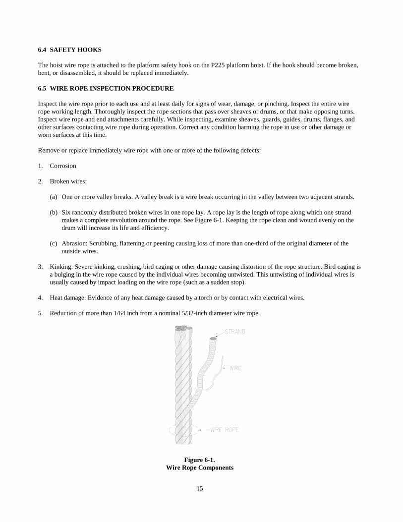
(a) One or more valley breaks. A valley break is a wire break occurring in the valley between two adjacent strands. (b) Six randomly distributed broken wires in one rope lay. A rope lay is the length of rope along which one strand
makes a complete revolution around the rope. See Figure 6-1. Keeping the rope clean and wound evenly on the drum will increase its life and efficiency.
(c) Abrasion: Scrubbing, flattening or peening causing loss of more than one-third of the original diameter of the
outside wires. 3. Kinking: Severe kinking, crushing, bird caging or other damage causing distortion of the rope structure. Bird caging is
a bulging in the wire rope caused by the individual wires becoming untwisted. This untwisting of individual wires is usually caused by impact loading on the wire rope (such as a sudden stop).
4. Heat damage: Evidence of any heat damage caused by a torch or by contact with electrical wires. 5. Reduction of more than 1/64 inch from a nominal 5/32-inch diameter wire rope.
Figure 6-1.
Wire Rope Components
15
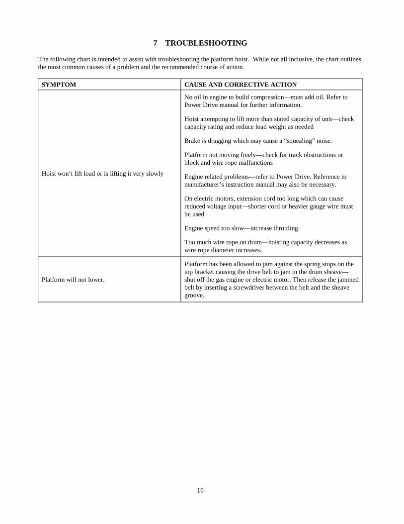
7 TROUBLESHOOTING The following chart is intended to assist with troubleshooting the platform hoist. While not all inclusive, the chart outlines the most common causes of a problem and the recommended course of action.
SYMPTOM CAUSE AND CORRECTIVE ACTION
Hoist won’t lift load or is lifting it very slowly
No oil in engine to build compression—must add oil. Refer to Power Drive manual for further information. Hoist attempting to lift more than stated capacity of unit—check capacity rating and reduce load weight as needed Brake is dragging which may cause a “squealing” noise. Platform not moving freely—check for track obstructions or block and wire rope malfunctions Engine related problems—refer to Power Drive. Reference to manufacturer’s instruction manual may also be necessary. On electric motors, extension cord too long which can cause reduced voltage input—shorter cord or heavier gauge wire must be used Engine speed too slow—increase throttling. Too much wire rope on drum—hoisting capacity decreases as wire rope diameter increases.
Platform will not lower.
Platform has been allowed to jam against the spring stops on the top bracket causing the drive belt to jam in the drum sheave—shut off the gas engine or electric motor. Then release the jammed belt by inserting a screwdriver between the belt and the sheave groove.
16
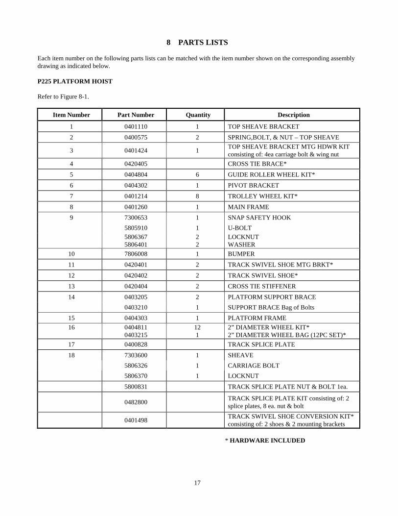
8 PARTS LISTS Each item number on the following parts lists can be matched with the item number shown on the corresponding assembly drawing as indicated below. P225 PLATFORM HOIST Refer to Figure 8-1.
Item Number Part Number Quantity Description
1 0401110 1 TOP SHEAVE BRACKET
2 0400575 2 SPRING,BOLT, & NUT – TOP SHEAVE
3 0401424 1 TOP SHEAVE BRACKET MTG HDWR KIT consisting of: 4ea carriage bolt & wing nut
4 0420405 CROSS TIE BRACE*
5 0404804 6 GUIDE ROLLER WHEEL KIT*
6 0404302 1 PIVOT BRACKET
7 0401214 8 TROLLEY WHEEL KIT*
8 0401260 1 MAIN FRAME 9 7300653 1 SNAP SAFETY HOOK 5805910 1 U-BOLT
5806367 5806401
2 2
LOCKNUT WASHER
10 7806008 1 BUMPER
11 0420401 2 TRACK SWIVEL SHOE MTG BRKT*
12 0420402 2 TRACK SWIVEL SHOE*
13 0420404 2 CROSS TIE STIFFENER
14 0403205 2 PLATFORM SUPPORT BRACE 0403210 1 SUPPORT BRACE Bag of Bolts
15 0404303 1 PLATFORM FRAME 16
0404811 0403215
12 1
2” DIAMETER WHEEL KIT* 2” DIAMETER WHEEL BAG (12PC SET)*
17 0400828 TRACK SPLICE PLATE
18 7303600 1 SHEAVE 5806326 1 CARRIAGE BOLT 5806370 1 LOCKNUT
5800831 TRACK SPLICE PLATE NUT & BOLT 1ea.
0482800 TRACK SPLICE PLATE KIT consisting of: 2 splice plates, 8 ea. nut & bolt
0401498 TRACK SWIVEL SHOE CONVERSION KIT* consisting of: 2 shoes & 2 mounting brackets
* HARDWARE INCLUDED
17
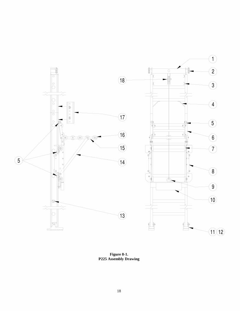
Figure 8-1. P225 Assembly Drawing
18
LIMITED PRODUCT WARRANTY
Reimann & Georger Corporation Hoisting and Construction Products
A. LIMITED WARRANTY Reimann & Georger Corporation (the “Manufacturer”) warrants to the original purchaser (the “Buyer”) that all Reimann & Georger Hoisting and Construction products shall be free of defects in material and workmanship for a period of one (1) year from date of original purchase.
B. MANUFACTURER’S OBLIGATIONS
The Manufacturer’s sole obligation under this Limited Warranty is the repair or, at the Manufacturer’s discretion, the replacement of parts found to be defective. Parts and equipment must have authorization from the Manufacturer prior to return to the Manufacturer or repair by an authorized service person. Costs of transportation and other expenses connected with replacing or repairing parts are not covered under this Limited Warranty.
C. PARTS MANUFACTURED BY OTHERS
This Limited Warranty does not cover any parts manufactured by others. Such parts are subject to the warranty, if any, of their respective manufacturers, and are to be repaired only by a respective authorized service person for such parts. The Manufacturer shall have no obligation to undertake repairs of parts manufactured by others.
D. NO SPECIAL, INCIDENTAL, OR CONSEQUENTIAL DAMAGES
IN NO EVENT SHALL THE MANUFACTURER BE LIABLE TO THE BUYER OR ANY OTHER PERSON FOR ANY INDIRECT, SPECIAL, INCIDENTAL OR CONSEQUENTIAL LOSSES OR DAMAGES CONNECTED WITH THE USE OF THE PRODUCT UNDER THIS LIMITED WARRANTY. SUCH DAMAGES FOR WHICH THE MANUFACTURER SHALL NOT BE RESPONSIBLE INCLUDE, BUT ARE NOT LIMITED TO, LOST TIME AND CONVENIENCE, LOSS OF USE OF THE PRODUCT, THE COST OF A PRODUCT RENTAL, COSTS OF GASOLINE, TELEPHONE, TRAVEL, OR LODGING, THE LOSS OF PERSONAL OR COMMERCIAL PROPERTY, AND THE LOSS OF REVENUE.
E. NO LIABILITY IN EXCESS OF PURCHASE PRICE IN NO EVENT SHALL THE MANUFACTURER’S OBLIGATIONS UNDER THIS LIMITED WARRANTY EXCEED THE PURCHASE PRICE OF THE PRODUCT.
F. NO EXTENSION OF STATUTE OF LIMITATIONS ANY REPAIRS PERFORMED UNDER THIS WARRANTY SHALL NOT IN ANY WAY EXTEND THE STATUTES OF LIMITATIONS FOR CLAIMS UNDER THIS LIMITED WARRANTY.
G. WAIVER OF OTHER WARRANTIES THE EXPRESS WARRANTIES SET FORTH IN THIS LIMITED WARRANTY ARE IN LIEU OF AND EXCLUDE ANY AND ALL OTHER WARRANTIES, EXPRESS OR IMPLIED, INCLUDING, BUT NOT LIMITED TO, THE IMPLIED WARRANTIES OR MERCHANTABILITY AND FITNESS FOR A PARTICULAR PURPOSE.
9912
H. PROCEDURE FOR WARRANTY PERFORMANCE If the product fails to perform to the Manufacturer’s specifications, the Buyer must provide the Manufacturer with the applicable model and serial numbers, the date of purchase, and the nature of the problem.
I. ADDITIONAL EXCLUSIONS FROM THIS LIMITED WARRANTY. THIS LIMITED WARRANTY DOES NOT COVER ANY OF THE FOLLOWING:
1. Equipment which has been abused, damaged, used beyond rated capacity, or repaired by persons other than
authorized service personnel. 2. Damage caused by acts of God which include, but are not limited to, hailstorms, windstorms, tornadoes,
sandstorms, lightning, floods, and earthquakes. 3. Damage under conditions caused by fire or accident, by abuse or by negligence of the user or any other person
other than the Manufacturer, by improper installation, by misuse, by incorrect operation, by “normal wear and tear”, by improper adjustment or alteration, by alterations not completed by authorized service personnel, or by failure of product parts from such alterations.
4. Costs of repairing damage caused by poor or improper maintenance, costs of normally scheduled maintenance, or
the cost of replacing any parts unless done as the result of an authorized repair covered by the one (1) year Limited Warranty.
5. Costs of modifying the product in any way once delivered to the Buyer, even if such modifications were added as
a production change on other products made after the Buyer’s product was built.
J. NO AUTHORITY TO ALTER THIS LIMITED WARRANTY No agent, representative, or distributor of the Manufacturer has any authority to alter the terms of this Limited Warranty in any way.