
p1527
4
Theoretical Simulation of Electromagnetic Behaviour of a Three-Dimensional TEM Cell working in Resonance V. Deniau (1)(2) , M. Klingler (3) , B. Demoulin (4) , J. Rioult (5) , J-P. Ghys (6) & T. K. Sarkar (7) (1) INRETS-LEOST, 20 rue Elisée Reclus 59650 Villeneuve D’Ascq, France, E-mail: [email protected] (2) TELICE -Université de Lille, Bâtiment P3 59655 Villeneuve d'Ascq, France (3) as (1) above, but E-mail: [email protected] (4) as (2) above, but E-mail: [email protected] (5) as (1) above, but E-mail: [email protected] (6) as (1) above, but E-mail: [email protected] (7) Department of Electrical and Computer Engineering, Syracuse University, New York, 13244-1240, USA, E-mail: [email protected] du ABSTRACT Hybrid chambers are new test facilities which were created to merge the electromagnetic properties of reverberating chambers and conventional TEM cells [1]. Particular models of hybrid chambers, Three-Dimensional TEM cells (3 - D TEM), were carried out to work in lower frequencies and to allow us to measure electromagnetic radiation of an equipment under test (EUT) according to three polarisation planes, without moving the EUT. This paper presents works on the optimisation of hybrid chamber and 3-D TEM cells carried out over the past two years. INTRODUCTION The electromagnetic emission created by printed circuit boards can be estimated using different measurement methods. The most applied method, which consists of measuring the far field emission with a wide-band receiving antenna inside an anechoic chamber, requires important investment mainly introduced by the cost of the anechoic chamber. Other methods have therefore been developed by exploiting properties of electromagnetic radiation as in the case of emission measurement techniques performed in TEM or GTEM cells. However, with these techniques, the measurement is restricted to the polarisation plane imposed by the reception of the field on a unique plate. This paper will present a new concept of hybrid chambers which would allow us to explore three fundamental orthogonal polarisation planes and obtain the total radiated power of the circuit under test without moving it. The second and third parts, will present a particular model called 3-D TEM cell and optimisation works carried out on this model. THE HYBRID REVERBERATING/THREE-DIMENSIONAL TEM CELL PROTOTYPE The first prototype was a hybrid chamber which was built in order to define the functioning principle. This generic prototype (Fig.1) was a parallelepiped metallic enclosure for which the dimensions were 109 x 97 x 80 cm. The cavity was equipped with three identical plates oriented in two-by-two orthogonal directions in order to explore the three fundamental orthogonal polarisation planes and to obtain the total radiated power of the circuit under test. The parallelepiped geometric enclosure was chosen to increase the density of reverberant modes above the first resonance frequency of the cavity in order to use the reverberation functioning of the enclosure in the higher frequencies as in a mode stirred reverberating chamber. Volume V Volume V Fig. 1. Prototype of a generic 3D-TEM cell. In this cavity, we can therefore make out two different functioning modes under and above the first resonance frequency of the enclosure. Assuming that for the ideal empty parallelepiped enclosure of dimensions a, b and d , the resonance frequencies are given by (1): 2 2 2 2 1 + + εµ = d p b n a m f p n m (1)
Transcript of p1527

8/4/2019 p1527
http://slidepdf.com/reader/full/p1527 1/4
Theoretical Simulation of Electromagnetic Behaviour of a Three-Dimensional TEM Cell
working in Resonance
V. Deniau(1)(2)
, M. Klingler (3)
, B. Demoulin(4)
, J. Rioult(5)
, J-P. Ghys(6)
& T. K. Sarkar (7)
(1) INRETS-LEOST, 20 rue Elisée Reclus 59650 Villeneuve D’Ascq, France, E-mail: [email protected]
(2)TELICE -Université de Lille, Bâtiment P3 59655 Villeneuve d'Ascq, France
(3)as (1) above, but E-mail: [email protected]
(4)as (2) above, but E-mail: [email protected]
(5)as (1) above, but E-mail: [email protected]
(6)as (1) above, but E-mail: [email protected]
(7) Department of Electrical and Computer Engineering, Syracuse University, New York, 13244-1240, USA,
E-mail: [email protected]
ABSTRACT
Hybrid chambers are new test facilities which were created to merge the electromagnetic properties of reverberatingchambers and conventional TEM cells [1]. Particular models of hybrid chambers, Three-Dimensional TEM cells(3 - D TEM), were carried out to work in lower frequencies and to allow us to measure electromagnetic radiation of
an equipment under test (EUT) according to three polarisation planes, without moving the EUT. This paper presentsworks on the optimisation of hybrid chamber and 3-D TEM cells carried out over the past two years.
INTRODUCTION
The electromagnetic emission created by printed circuit boards can be estimated using different measurement
methods. The most applied method, which consists of measuring the far field emission with a wide-band receivingantenna inside an anechoic chamber, requires important investment mainly introduced by the cost of the anechoic
chamber. Other methods have therefore been developed by exploiting properties of electromagnetic radiation as inthe case of emission measurement techniques performed in TEM or GTEM cells. However, with these techniques,
the measurement is restricted to the polarisation plane imposed by the reception of the field on a unique plate.This paper will present a new concept of hybrid chambers which would allow us to explore three fundamentalorthogonal polarisation planes and obtain the total radiated power of the circuit under test without moving it. Thesecond and third parts, will present a particular model called 3-D TEM cell and optimisation works carried out on
this model.
THE HYBRID REVERBERATING/THREE-DIMENSIONAL TEM CELL PROTOTYPE
The first prototype was a hybrid chamber which was built in order to
define the functioning principle. This generic prototype (Fig.1) was a parallelepiped metallic enclosure for which the dimensions were109 x 97 x 80 cm. The cavity was equipped with three identical
plates oriented in two-by-two orthogonal directions in order toexplore the three fundamental orthogonal polarisation planes and toobtain the total radiated power of the circuit under test.The parallelepiped geometric enclosure was chosen to increase thedensity of reverberant modes above the first resonance frequency of the cavity in order to use the reverberation functioning of the
enclosure in the higher frequencies as in a mode stirred reverberatingchamber.
Volume VVolume V
Fig. 1. Prototype of a generic 3D-TEM cell.
In this cavity, we can therefore make out two different functioning modes under and above the first resonancefrequency of the enclosure. Assuming that for the ideal empty parallelepiped enclosure of dimensions a, b and d ,
the resonance frequencies are given by (1):
222
2
1
+
+
εµ=
d
p
b
n
a
m f pnm
(1)
8/4/2019 p1527
http://slidepdf.com/reader/full/p1527 2/4
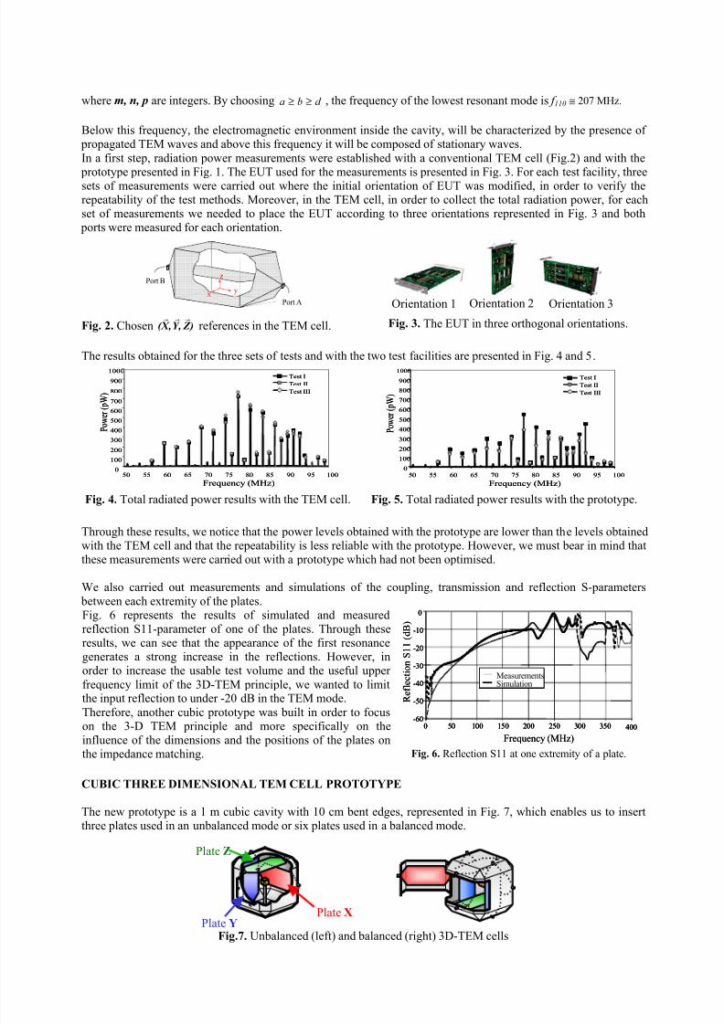
where m, n, p are integers. By choosing d ba ≥≥ , the frequency of the lowest resonant mode is f 110 ≅ 207 MHz.
Below this frequency, the electromagnetic environment inside the cavity, will be characterized by the presence of propagated TEM waves and above this frequency it will be composed of stationary waves.
In a first step, radiation power measurements were established with a conventional TEM cell (Fig.2) and with the prototype presented in Fig. 1. The EUT used for the measurements is presented in Fig. 3. For each test facility, threesets of measurements were carried out where the initial orientation of EUT was modified, in order to verify therepeatability of the test methods. Moreover, in the TEM cell, in order to collect the total radiation power, for eachset of measurements we needed to place the EUT according to three orientations represented in Fig. 3 and both ports were measured for each orientation.
z
yx
Port B
Port A
Fig. 2. Chosen ) Z ,Y , X ( rrr
references in the TEM cell. Fig. 3. The EUT in three orthogonal orientations.
The results obtained for the three sets of tests and with the two test facilities are presented in Fig. 4 and 5.
50 55 60 65 70 75 80 85 90 95 100
Frequency (MHz)
0
100
200
300
400
500
600
700
800
900
1000
P o w e r ( p W )
Test I
Test II
Test III
50 55 60 65 70 75 80 85 90 95 100
Frequency (MHz)
0
100
200
300
400
500
600
700
800
900
1000
P o w e r ( p W )
Test I
Test II
Test III
Test I
Test II
Test III
0
100
200
300
400
500
600
700
800
900
1000
50 55 60 65 70 75 80 85 90 95 100
Frequency (MHz)
P o w e r ( p W )
Test I
Test II
Test III
0
100
200
300
400
500
600
700
800
900
1000
50 55 60 65 70 75 80 85 90 95 100
Frequency (MHz)
P o w e r ( p W )
Test I
Test II
Test III
Fig. 4. Total radiated power results with the TEM cell. Fig. 5. Total radiated power results with the prototype.
Through these results, we notice that the power levels obtained with the prototype are lower than the levels obtainedwith the TEM cell and that the repeatability is less reliable with the prototype. However, we must bear in mind thatthese measurements were carried out with a prototype which had not been optimised.
We also carried out measurements and simulations of the coupling, transmission and reflection S-parameters
between each extremity of the plates.Fig. 6 represents the results of simulated and measuredreflection S11-parameter of one of the plates. Through theseresults, we can see that the appearance of the first resonancegenerates a strong increase in the reflections. However, inorder to increase the usable test volume and the useful upper
frequency limit of the 3D-TEM principle, we wanted to limitthe input reflection to under -20 dB in the TEM mode.
Therefore, another cubic prototype was built in order to focuson the 3-D TEM principle and more specifically on theinfluence of the dimensions and the positions of the plates onthe impedance matching.
-60
-50
-40
-30
-20
-10
0
0 50 100 150 200 250 300 350 400
Frequency (MHz)
R e f l e c t i o n S 1 1 ( d B )
MeasurementsSimulation
-60
-50
-40
-30
-20
-10
0
-60
-50
-40
-30
-20
-10
0
0 50 100 150 200 250 300 350 4000 50 100 150 200 250 300 350 400
Frequency (MHz)
R e f l e c t i o n S 1 1 ( d B )
MeasurementsSimulation
Fig. 6. Reflection S11 at one extremity of a plate.
CUBIC THREE DIMENSIONAL TEM CELL PROTOTYPE
The new prototype is a 1 m cubic cavity with 10 cm bent edges, represented in Fig. 7, which enables us to insertthree plates used in an unbalanced mode or six plates used in a balanced mode.
Fig.7. Unbalanced (left) and balanced (right) 3D-TEM cells
Orientation 1 Orientation 2 Orientation 3
Plate Z
Plate YPlate X
8/4/2019 p1527
http://slidepdf.com/reader/full/p1527 3/4
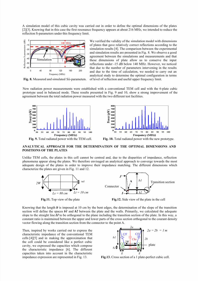
A simulation model of this cubic cavity was carried out in order to define the optimal dimensions of the plates[2][3]. Knowing that in this case the first resonance frequency appears at about 216 MHz, we intended to reduce thereflection S-parameters under this frequency limit.
-60
-50
-40
-30
-20
-10
0
0 40 80 120 160 200
Frequency (MHz)
R e f l e c t i o n S - p a r a m e
t e r s ( d B )
Fig. 8. Measured and simulated Sii-parameters.
We verified the validity of the simulation model with dimensionsof plates that gave relatively correct reflections according to the
simulation results [4]. The comparison between the experimentaland simulation results are presented in Fig. 8. We observe a goodagreement between the simulations and measurements and thatthese dimensions of plate allow us to conserve the input
reflections under -15 dB below 140 MHz. However, we noticedthat due to the number of parameters intervening in the resultsand due to the time of calculation, we needed to carry out ananalytical study to determine the optimal configuration in termsof level of reflection and useful upper frequency limit.
New radiation power measurements were established with a conventional TEM cell and with the 6-plate cubic prototype used in balanced mode. These results presented in Fig. 9 and 10, show a strong improvement of theagreement between the total radiation power measured with the two different test facilities.
50 55 60 65 70 75 80 85 90 95 100
Frequency (MHz)
0
100
200
300
400
500
600
700
800
P o w e r ( p W )
50 55 60 65 70 75 80 85 90 95 100
Frequency (MHz)
0
100
200
300
400
500
600
700
800
0
100
200
300
400
500
600
700
800
P o w e r ( p W )
50 55 60 65 70 75 80 85 90 95 100
Frequency (MHz)
0
100
200
300
400
500
600
700
800
P o w e r ( p W )
50 55 60 65 70 75 80 85 90 95 100
Frequency (MHz)
0
100
200
300
400
500
600
700
800
0
100
200
300
400
500
600
700
800
P o w e r ( p W )
Fig. 9. Total radiated power with the TEM cell. Fig. 10. Total radiated power with the new prototype.
ANALYTICAL APPROACH FOR THE DETERMINATION OF THE OPTIMAL DIMENSIONS ANDPOSITIONS OF THE PLATES
Unlike TEM cells, the plates in this cell cannot be centred and, due to the disparities of impedance, reflection phenomena appear along the plates. We therefore envisaged an analytical approach to converge towards the mostadequate design of the plates in order to improve their impedance matching. The different dimensions whichcharacterize the plates are given in Fig. 11 and 12.
Fig.11. Top view of the plate Fig.12. Side view of the plate in the cell
Knowing that the length lt is imposed at 10 cm by the bent edges, the determination of the slope of the transitionsection will define the spaces b1 and b2 between the plate and the walls. Primarily, we calculated the adequateslope to the straight line IJ to be orthogonal to the plane including the transition section of the plate. In this way, aconstant ratio is maintained between the upper and lower parts of the cross section orthogonal to the courant densityvector flowing along the transition section from the connector to the point A.
Then, inspired by works carried out to express thecharacteristic impedance of the conventional TEMcells [4][5] and in making the approximation thatthe cell could be considered like a perfect cubic
cavity, we expressed the capacities which composethe characteristic impedance [6]. The differentcapacities taken into account in the characteristicimpedance expression are represented in Fig. 13.
2a = 2b = 1 m
Fig.13. Cross section of a 1 plate-perfect cubic cell.
2W wt
Lt = 10 cm Ls = 80 cm
Simulation
140 MHz
Transition section
J
I
b1
b2
Connector
A
g
plate
2a
2W 2b
b2
b1Cf1
Cf2
Chs
Chi
Cf2
Cf1
g

8/4/2019 p1527
http://slidepdf.com/reader/full/p1527 4/4
Assuming that the total capacitance of an unsymmetrical cross section is the sum of each individual capacitance, theassociated expressions for each capacitance were used to obtain the characteristic impedance (2).
++
+++
≅
22coth1ln
22
12coth1ln
22
2
2
1
2
62.376
b
g
b
g
b
W
b
W Z c
π
π
π
π
(2)
Where g can be expressed in function of a and W .
In integrating the values of b1 and b2 giving the adequate slope in this analytical expression (2), we extracted the
value of W , which permitted us to have Zc = 50 Ω. However, the impact of the width wt of the ends of the plates isnot taken into account in this method. We therefore defined the value of wt by simulation. That was relatively easy
assuming that all the other dimensions were already fixed and that only one parameter would vary.The simulation and experimental results obtained with the final dimensions which are b2 = 11 cm, 2W = 50 cm andwt = 2 cm, are presented in Fig. 14.
-60
-50
-40
-30
-20
-10
0
0 40 80 120 160 200
Frequency (MHz)
R e f l e c t i o n S - p a r a m e t e
r s ( d B )
Fig.14. Measured and simulated Sii-parameters.
In Fig. 14, we can see that the results given by thesimulation are very satisfying as the reflection S-
parameter is below -20 dB up to 182 MHz. We canalso observe significant differences between thesimulation and the measurement and between themeasured S-parameters of the different plates. Thesedifferences probably come from the real cavity’simperfections. However, in the worst case, the
measured reflections stay below -15 dB under 182MHz, which is relatively satisfying. Furthermore, sincein the best case the reflections are less than -20 dB below 175 MHz and less than -15 dB below 190 MHz,these results could be better for certain plates inimproving the real model.
CONCLUSION
Through the results presented in this paper, we saw that in using a balanced 6-plate 3D-TEM cell, we obtainedexcellent agreement with the total radiated power measurements obtained in a conventional TEM cell. We also presented a method to determine the optimal dimensions of the plates enabling us to reduce the reflections along the plates. This method allowed us to conserve the reflection S-parameters below -15 dB under 190 MHz, in a cavitywhere the first resonance appears at 216 MHz.
In the next step, we will apply this method to equip a mode stirred reverberating chamber in order to use it in thelow frequencies according to the three dimensional principle. In this work, we will have to take into account the physical contraints of the new cavity and we will also have to study the impact of the plates on the reverberatingfunctioning.
REFERENCES
[1] M. Klingler, S. Egot, J.P. Ghys and J. Rioult, “On the Use of Three-Dimensional TEM Cells for Total Radiated Power Measurements”, 2001 Int. Symposium on EMC, Montreal, August 2001.
[2] B. M. Kolundzija, J.S. Ognjanovic & T.K. Sarkar, WIPL-D, “ Electromagnetic modelling of composite metallicand dielectric structure, Software and User manual ”, Boston, Artech House, 2000.
[3] V. Deniau, M. Klingler & B. Demoulin, “Characterisation of Cubic Three-Dimensional TEM Cells”, Telecom
2001 et 2ème
JFMMA, Casablanca, Octobre 2001.[4] M. L. Crawford, “Generation of Standard EM Fields Using TEM Transmission Cells”, IEEE Trans. On
Electromagnetic Compatibility, vol. EMC-16, NO. 4, pp. 189-195, November 1974.[5] J. C. Tippet & D. C. Chang, “ Radiation Characteristics of Dipole Sources Located Inside a Rectangular,
Coaxial Transmission Line”, NBSIR 75-829, January 1976.[6] V. Deniau, M. Klingler & B. Demoulin , “ Research of the Optimal Dimensions and Position of the Plates in a
3D-TEM Cell”, to be issued 5th
International Symposium on Electromagnetic Compatibility “EMC Europe
2002”, Sorrento, September 2002.
Simulation
182 MHz
Best case


