P-MU-AD500 - Gianni · Must provide at least 10 seconds of rest time between every new cycle to...
17
AD500 Instruction Manual Automatic Door Operator
Transcript of P-MU-AD500 - Gianni · Must provide at least 10 seconds of rest time between every new cycle to...

AD500
Instruction Manual
Automatic Door Operator

Table of Contents
General Safety Precautions -------------------------------------------
Declaration by Manufacturer -------------------------------------------
Introduction ---------------------------------------------------------------
Product Features --------------------------------------------------------
Part Identification --------------------------------------------------------
Specifications -------------------------------------------------------------
How the AD500 Works --------------------------------------------------
Pre-Installation -----------------------------------------------------------
Template Instructions ---------------------------------------------------
Installation (Video Instructions) ---------------------------------------
Trouble Shooting ---------------------------------------------------------
Maintenance ---------------------------------------------------------------
Safety Instructions for Users -------------------------------------------
01
01
02
02
02
03
04
09
11
12
12
13
15
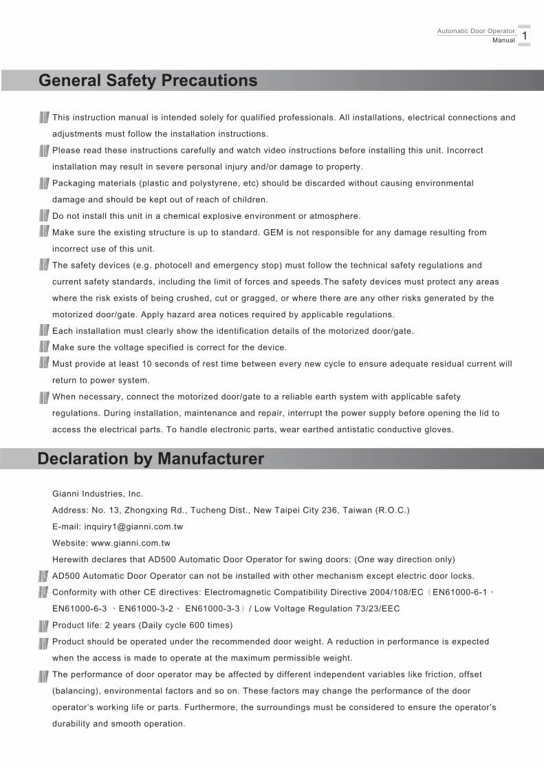
This instruction manual is intended solely for qualified professionals. All installations, electrical connections and
adjustments must follow the installation instructions.
Please read these instructions carefully and watch video instructions before installing this unit. Incorrect
installation may result in severe personal injury and/or damage to property.
Packaging materials (plastic and polystyrene, etc) should be discarded without causing environmental
damage and should be kept out of reach of children.
Do not install this unit in a chemical explosive environment or atmosphere.
Make sure the existing structure is up to standard. GEM is not responsible for any damage resulting from
incorrect use of this unit.
The safety devices (e.g. photocell and emergency stop) must follow the technical safety regulations and
current safety standards, including the limit of forces and speeds.The safety devices must protect any areas
where the risk exists of being crushed, cut or gragged, or where there are any other risks generated by the
motorized door/gate. Apply hazard area notices required by applicable regulations.
Each installation must clearly show the identification details of the motorized door/gate.
Make sure the voltage specified is correct for the device.
Must provide at least 10 seconds of rest time between every new cycle to ensure adequate residual current will
return to power system.
When necessary, connect the motorized door/gate to a reliable earth system with applicable safety
regulations. During installation, maintenance and repair, interrupt the power supply before opening the lid to
access the electrical parts. To handle electronic parts, wear earthed antistatic conductive gloves.
1Automatic Door Operator Manual
General Safety Precautions
Declaration by Manufacturer
Gianni Industries, Inc.
Address: No. 13, Zhongxing Rd., Tucheng Dist., New Taipei City 236, Taiwan (R.O.C.)
E-mail: [email protected]
Website: www.gianni.com.tw
Herewith declares that AD500 Automatic Door Operator for swing doors: (One way direction only)
AD500 Automatic Door Operator can not be installed with other mechanism except electric door locks.
Conformity with other CE directives: Electromagnetic Compatibility Directive 2004/108/EC(EN61000-6-1、
EN61000-6-3 、EN61000-3-2、 EN61000-3-3)/ Low Voltage Regulation 73/23/EEC
Product life: 2 years (Daily cycle 600 times)
Product should be operated under the recommended door weight. A reduction in performance is expected
when the access is made to operate at the maximum permissible weight.
The performance of door operator may be affected by different independent variables like friction, offset
(balancing), environmental factors and so on. These factors may change the performance of the door
operator’s working life or parts. Furthermore, the surroundings must be considered to ensure the operator’s
durability and smooth operation.

1
2
43
9
5
78
10
12
6
13
Operates from 100 to 240 VAC
Automatic Door Operator Manual2
The AD500 is a swing door operator for a wide range of applications. It can be mounted on either side
of the door header for pull or push action, and suitable for single or double, inward or outward opening,
left or right handed doors. It also offers numerous adjustable features and can be integrated with electric
locks or access control systems to ensure all around safety.
Introduction
Product Features
Non - handed
Pull or push side mounting
Obstruction detection - If the door is obstructed during operation, the operator will stopthe door and reverse movement
1. Cover
2. Base plate
3. Top end plate
4. Bottom end plate
5. Control unit
6. Reducer
7. Turbine box
8. Turbine box cover
9. Motor
10. Track assembly
11. Track block
12. Sliding arm
13. Power On/OFF switch
Part Identification
Backup battery input for emergency power supply
Operates with infrared safety sensors, wall push buttons, card readers, or radio frequency devices
Adjustment of hold-up time, opening/closing speed, and opening angle
Easy integration with electric locking devices and access control systems
11
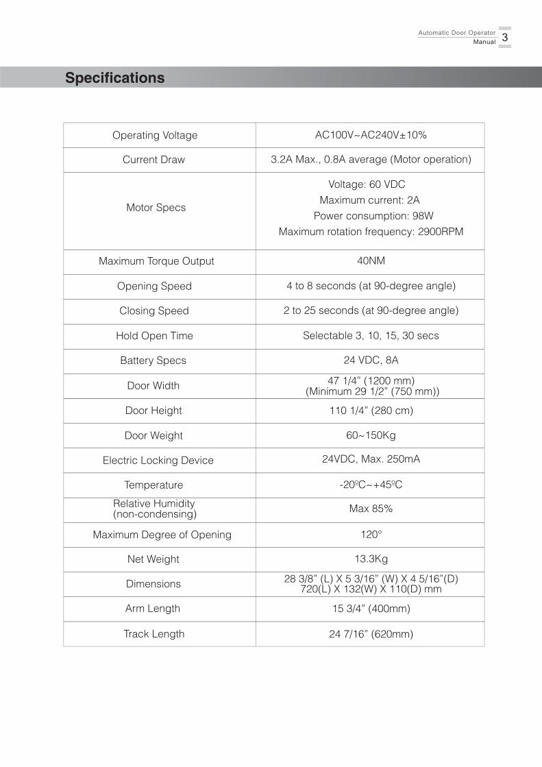
Specifications
Operating Voltage
Current Draw
AC100V~AC240V±10%
3.2A Max., 0.8A average (Motor operation)
Motor Specs
Voltage: 60 VDC
Maximum current: 2A
Power consumption: 98W
Maximum rotation frequency: 2900RPM
Maximum Torque Output 40NM
Opening Speed 4 to 8 seconds (at 90-degree angle)
Closing Speed 2 to 25 seconds (at 90-degree angle)
Hold Open Time Selectable 3, 10, 15, 30 secs
Battery Specs 24 VDC, 8A
Door Width 47 1/4” (1200 mm)
Door Weight 60~150Kg
Electric Locking Device 24VDC, Max. 250mA
Temperature -20ºC~+45ºC
Relative Humidity(non-condensing) Max 85%
Maximum Degree of Opening 120°
Net Weight 13.3Kg
Dimensions 720(L) X 132(W) X 110(D) mm
Arm Length 15 3/4” (400mm)
Door Height 110 1/4” (280 cm)
Track Length 24 7/16” (620mm)
3Automatic Door Operator Manual
28 3/8” (L) X 5 3/16” (W) X 4 5/16”(D)
(Minimum 29 1/2” (750 mm))

The AD500 automatic door operator uses a DC motor to open the door. It closes the door by motor
and spring force.
When an opening signal is received by the control unit, the door is opened at the operator-adjusted
opening speed until it reaches the back check position, where it decelerates to slow speed.
The door will stop at the Hold Open position and remain there.
When the hold open time has elapsed, the operator will close the door automatically. The door is
closed at the operator-adjusted speed until it reaches to the latch check position, where it
decelerates to slow speed. The door is kept closed by spring or motor force.
Hold Open Position
Deceleration
Back Check
Latch Check
Closing Speed
Automatic Door Operator Manual4
How the AD500 Works
Opening Cycle Closing Cycle
To Fully Opened
Opening Speed
Deceleration To Fully Closed

DC Power
Relay
Relay
Relay
Relay
Back Check/Latch Check Angle
Closing Speed
Opening Speed
ActivationDevice 3Input
ActivationDevice 2 Input
24VDCOutput
Encoder
Motor
Backup Battery Input
Activation Switch(Activation Device1 input)
Hold Open Switch
Push &Go / AutomaticMode Switch
Manual Mode Switch
IR Sensor Input(on hinge (pull) side)
IR Sensor Input(on opposite hinge (push) side)
Make sure the voltage specified is correct for the device.
For safety, we recommend using a fail-safe electric lock in case of emergencies or power interruptions.
Control Unit
LED1LED2
LED3
ActivationHoldOpen
Auto/Push &GoManual
5Automatic Door Operator Manual
Electric Locking Device
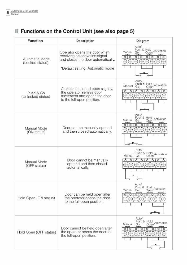
Automatic Door Operator Manual6
Automatic Mode (Locked status)
Functions on the Control Unit (see also page 5)
Function Description Diagram
Operator opens the door when receiving an activation signal and closes the door automatically.
*Default setting: Automatic mode
Push & Go(Unlocked status)
As door is pushed open slightly,the operator senses doormovement and opens the doorto the full-open position.
Manual Mode (ON status)
Door can be manually opened and then closed automatically.
Manual Mode (OFF status)
Door cannot be manually opened and then closed automatically.
Hold Open (ON status)Door can be held open after the operator opens the door to the full-open position.
Hold Open (OFF status)Door cannot be held open after the operator opens the door to the full-open position.
ActivationHoldOpen
Auto/Push &GoManual
ActivationHoldOpen
Auto/Push &GoManual
ActivationHoldOpen
Auto/Push &GoManual
ActivationHoldOpen
Auto/Push &GoManual
ActivationHoldOpen
Auto/Push &GoManual
ActivationHoldOpen
Auto/Push &GoManual

7Automatic Door Operator Manual
+ -
+ -
*For automatic mode, 0.7 second motor start delay allows the electric locking device to release first.
Function Description Diagram
Activation Input 1 (ON status)
Operator is activated by Activation Device 1.
Activation Input 1 (OFF status)
Activation Input 2 Operator is activated by Activation Device 2.
Activation Input 3Operator is activated by Activation Device 3.
Infrared Sensor Input(On the hinge (pull) side)
Monitoring of IR impulse or detection
Infrared Sensor Input(On the oppositehinge (push) side)
Monitoring of IR impulse or detection
ActivationHoldOpen
Auto/Push &GoManual
ActivationHoldOpen
Auto/Push &GoManual
Activation Device 2
Activation Device 3
Functions on the Control Unit (see also page 5) (Continued)
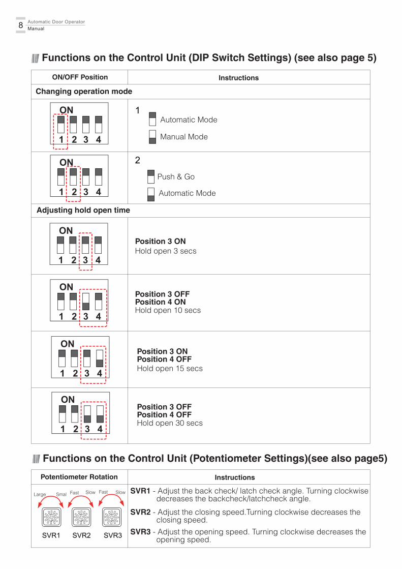
Functions on the Control Unit (Potentiometer Settings)(see also page5)
ON/OFF Position Instructions
1
2
1 2 3 4
ON
1 2 3 4
ON
Automatic Mode
Push & Go
1 2 3 4
ONPosition 3 ON
1 2 3 4
ON
1 2 3 4
ON
Position 3 OFFPosition 4 ON
Position 3 ONPosition 4 OFF
1 2 3 4
ONPosition 3 OFFPosition 4 OFF
Functions on the Control Unit (DIP Switch Settings) (see also page 5)
Potentiometer Rotation Instructions
SVR1 SVR2 SVR3
SmalLarge
Manual Mode
Automatic Mode
Changing operation mode
Adjusting hold open time
Hold open 3 secs
Hold open 10 secs
Hold open 15 secs
Hold open 30 secs
SVR1 - Adjust the back check/ latch check angle. Turning clockwise decreases the backcheck/latchcheck angle.
Automatic Door Operator Manual8
Fast SlowFast Slow
SVR3 - Adjust the opening speed. Turning clockwise decreases the opening speed.
SVR2 - Adjust the closing speed.Turning clockwise decreases the closing speed.
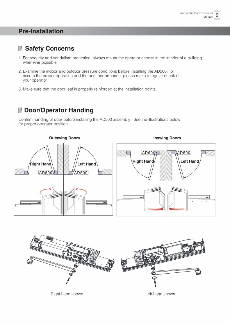
Safety Concerns
Pre-Installation
AD500AD500
Outswing Doors
Left HandRight Hand
AD500AD500
Inswing Doors
Left HandRight Hand
9Automatic Door Operator Manual
1. For security and vandalism protection, always mount the operator access in the interior of a building whenever possible.
2. Examine the indoor and outdoor pressure conditions before installing the AD500. To assure the proper operation and the best performance, please make a regular check of your operator.
3. Make sure that the door leaf is properly reinforced at the installation points.
Door/Operator HandingConfirm handing of door before installing the AD500 assembly . See the illustrations belowfor proper operator position.
Right hand shown Left hand shown
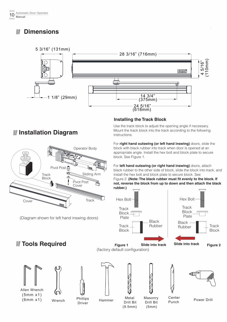
Installation Diagram
Automatic Door Operator Manual10
Tools Required
(5mm x1)(6mm x1)
Allen Wrench
Wrench Phillips Driver
Hammer Metal Drill Bit(9.5mm)
CenterPunch
Power Drill
28 3/16” (716mm)
(110
mm
)
(375mm)
(618mm)24 5/16”
Dimensions
4 5/
16”
14 3/4”
5 3/16” (131mm)
1 1/8” (29mm)
Masonry Drill Bit (5mm)
(Diagram shown for left hand inswing doors)
Installing the Track BlockUse the track block to adjust the opening angle if necessary.Mount the track block into the track according to the followinginstructions.
For right hand outswing (or left hand inswing) doors, slide theblock with black rubber into track when door is opened at anappropriate angle. Install the hex bolt and block plate to secureblock. See Figure 1.
For left hand outswing (or right hand inswing) doors, attachblack rubber to the other side of block, slide the block into track, andinstall the hex bolt and block plate to secure block. SeeFigure 2. (Note: The black rubber must fit evenly to the block. Ifnot, reverse the block from up to down and then attach the blackrubber.)
Hex Bolt
Track Block Plate
BlackRubberTrack
Block
Hex Bolt
Track Block Plate
BlackRubber Track
Block
Figure 1(factory default configuration)
Figure 2Slide into track Slide into track
Operator Body
Sliding Arm
Pivot PostCover
Track
TrackBlock
Pivot Post
Cover
Door
DoorDoor
2 15/16” (74.5mm)
Door
Door
DoorDoor
Door
11Automatic Door Operator Manual
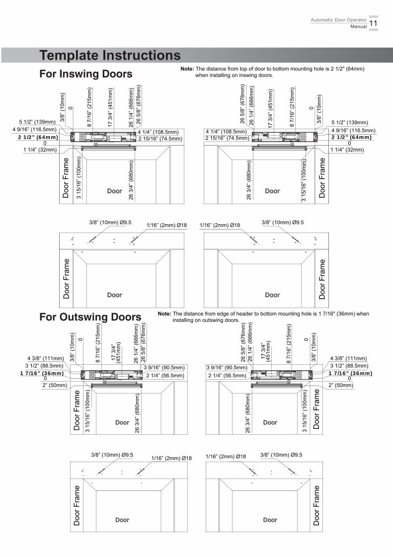
Template Instructions
Doo
r Fra
me
Doo
r Fra
me
Doo
r Fra
me
Doo
r Fra
me
Doo
r Fra
me
Doo
r Fra
me
Doo
r Fra
me
Doo
r Fra
me
5 1/2” (139mm)4 9/16” (116.5mm)2 1/2” (64mm)
1 1/4” (32mm)0
3 15
/16”
(100
mm
)
26 3
/4” (
680m
m)
03/
8” (1
0mm
)
8 7/
16” (
215m
m)
17 3
/4” (
451m
m)
26 1
/4” (
666m
m)
26 5
/8” (
676m
m)
4 1/4” (108.5mm)2 15/16” (74.5mm)
26 3
/4” (
680m
m)
3 15
/16”
(100
mm
)
1 1/4” (32mm)
5 1/2” (139mm)4 9/16” (116.5mm)
0
17 3
/4” (
451m
m)
8 7/
16” (
215m
m)
0
26 1
/4” (
666m
m)
26 5
/8” (
676m
m)
4 1/4” (108.5mm)
3/8”
(10m
m)
1/16” (2mm) Ø183/8” (10mm) Ø9.5 1/16” (2mm) Ø18 3/8” (10mm) Ø9.5
4 3/8” (111mm)3 1/2” (88.5mm)1 7/16” (36mm)
2” (50mm)0
3 15
/16”
(100
mm
)
26 3
/4” (
680m
m)
3 15
/16”
(100
mm
)
26 3
/4” (
680m
m)
1/16” (2mm) Ø183/8” (10mm) Ø9.5 1/16” (2mm) Ø18 3/8” (10mm) Ø9.5
03/
8” (1
0mm
)
8 7/
16” (
215m
m)
17 3
/4”
26 1
/4” (
666m
m)
26 5
/8” (
676m
m)
3 9/16” (90.5mm)2 1/4” (56.5mm)
(451
mm
)
3 9/16” (90.5mm)2 1/4” (56.5mm)
4 3/8” (111mm)3 1/2” (88.5mm)
1 7/16” (36mm)
2” (50mm)0
26 1
/4” (
666m
m)
26 5
/8” (
676m
m)
3/8”
(10m
m)
0
8 7/
16” (
215m
m)
17 3
/4”
(451
mm
)
For Inswing Doors
For Outswing Doors
Note: The distance from top of door to bottom mounting hole is 2 1/2" (64mm) when installing on inswing doors.
2 1/2” (64mm)
Note: The distance from edge of header to bottom mounting hole is 1 7/16" (36mm) when installing on outswing doors.
Automatic Door Operator Manual12
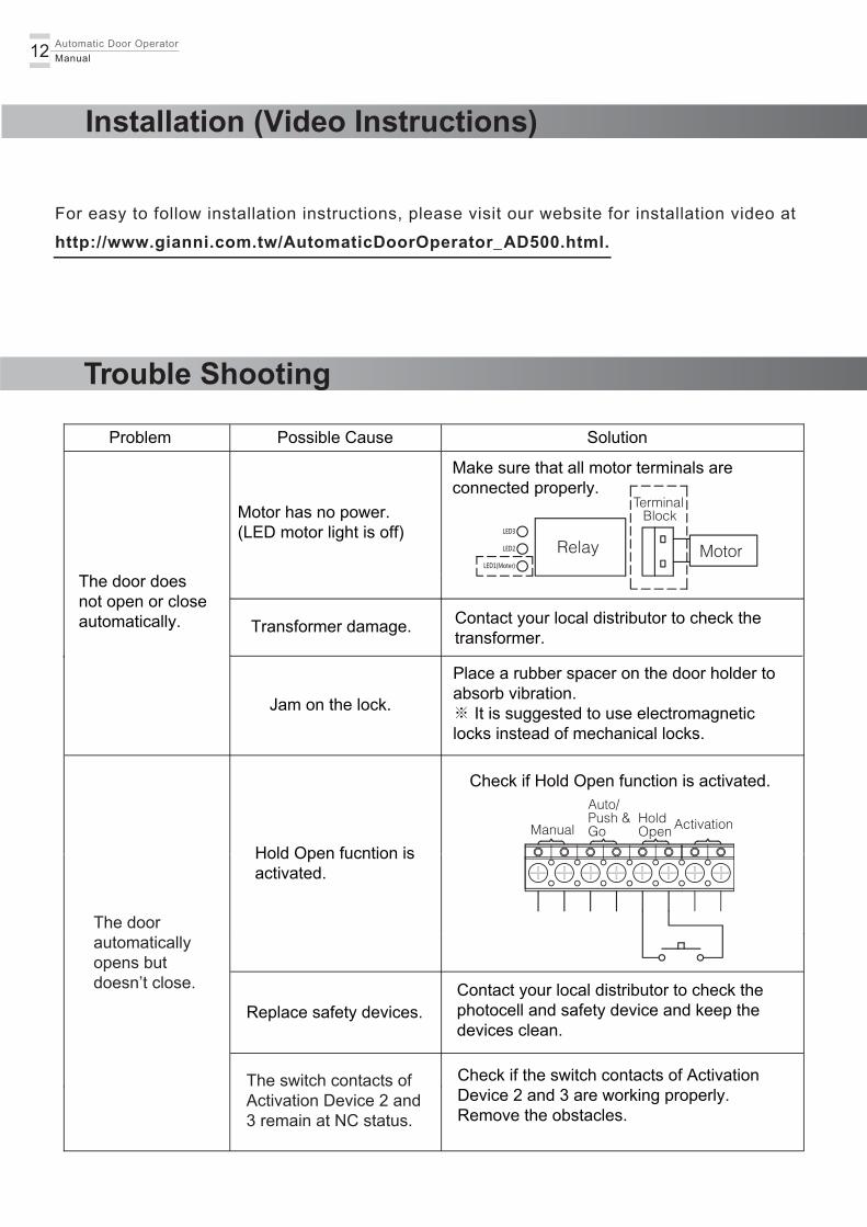
Installation (Video Instructions)
For easy to follow installation instructions, please visit our website for installation video at
http://www.gianni.com.tw/AutomaticDoorOperator_AD500.html.
Trouble Shooting
The door doesnot open or closeautomatically.
Motor has no power.(LED motor light is off)
Make sure that all motor terminals areconnected properly.
Problem Possible Cause Solution
Transformer damage. Contact your local distributor to check thetransformer.
Jam on the lock.
Place a rubber spacer on the door holder to absorb vibration. ※ It is suggested to use electromagneticlocks instead of mechanical locks.
Check if the switch contacts of ActivationDevice 2 and 3 are working properly.Remove the obstacles.
Replace safety devices.Contact your local distributor to check thephotocell and safety device and keep thedevices clean.
Hold Open fucntion isactivated.
ActivationHoldOpen
Auto/Push &GoManual
Relay Motor
TerminalBlock
Check if Hold Open function is activated.
The doorautomaticallyopens butdoesn’t close.
The switch contacts ofActivation Device 2 and3 remain at NC status.
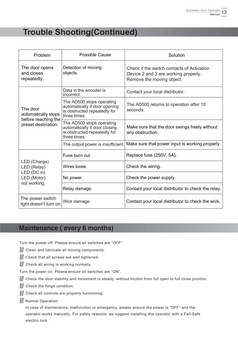
Normal Operation:
In case of maintenance, malfunction or emergency, please ensure the power is “OFF” and the
operator works manually. For safety reasons, we suggest installing this operator with a Fail-Safe
electric lock.
Turn the power off. Please ensure all switches are “OFF”
Clean and lubricate all moving components.
Check that all screws are well tightened.
Check all wiring is working normally.
Turn the power on. Please ensure all switches are “ON”.
Check the door stability and movement is steady, without friction from full open to full close position.
Check the hinge condition.
Check all controls are properly functioning.
Maintenance ( every 6 months)
The AD500 stops operatingautomatically if door opening is obstructed repeatedly for three times.
The AD500 returns to operation after 10 seconds.The door
automatically stops before reaching the preset destination. Make sure that the door swings freely without
any obstruction.
Make sure that power input is working properly.
Fuse burn out. Replace fuse (250V, 5A).
Wires loose.
No power. Check the power supply.
Contact your local distributor to check the relay.
Contact your local distributor to check the wick.
Relay damage.
Check the wiring.
Problem Possible Cause Solution
LED (Charge)LED (Relay)LED (DC in)LED (Motor)not working.
The power switch light doesn’t turn on.
13Automatic Door Operator Manual
Trouble Shooting(Continued)
The door opens and closes repeatedly.
Detection of moving objects.
Check if the switch contacts of ActivationDevice 2 and 3 are working properly.Remove the moving object.
Data in the encoder is incorrect. Contact your local distributor.
The AD500 stops operatingautomatically if door closing is obstructed repeatedly for three times.The output power is insufficient.
Wick damage.

Automatic Door Operator Manual14
Safety Instructions for Users
These instructions must be accessible to all potential users.
The product must be used in visible place.
GEM is not responsible for any damage caused by improper use of this unit.
Do not use with the other door closer.
Do not put any obstacle in the door path when operating.
Do not allow children to play with the AD500. Keep remote control or any other control devices out
reach of children to avoid an unexpected accident.
Work on electrical equipment may only be performed by qualified electricians.
Contact qualified personnel to make regular maintenance checks. All installation, maintenance and
repair work must be documented and made available to the user.
The following instructions are essential to users.
Read these instructions below carefully as it contains important information about safety and maintenance.
Copyright © A ll Rights Reserved.
P-MU-AD500 Published: 2018.02.13
AD500
Instruct ion ManualAutomat ic Door Operator