
Oxygen and nitrogen Industries
20
26/09/2013 1 Oxygen and Nitrogen Uses • Oxygen – It is used to produce oxyacetylene flame to cut and weld the metals – Used in oxygen steelmaking process – Used as artificial respiration for patients – Used by mountain climbers, sea divers and high attitude airplane pilots • Nitrogen – Used in manufacture of synthetic nitrogen oxide, ammonia, nitric acid – Used in manufacture of organic nitrates e.g; propellants and explosives – Synthetically produced nitrates are key ingredients of industrial fertilizers – Applied to create inert atmosphere
-
Upload
saffi-ud-din-ahmad -
Category
Engineering
-
view
574 -
download
4
Transcript of Oxygen and nitrogen Industries

26/09/2013
1
Oxygen and Nitrogen
Uses
• Oxygen – It is used to produce oxyacetylene flame to cut and weld the metals – Used in oxygen steelmaking process– Used as artificial respiration for patients – Used by mountain climbers, sea divers and high attitude airplane
pilots
• Nitrogen – Used in manufacture of synthetic nitrogen oxide, ammonia, nitric acid – Used in manufacture of organic nitrates e.g; propellants and
explosives– Synthetically produced nitrates are key ingredients of industrial
fertilizers – Applied to create inert atmosphere
Abdul Samad
Highlight

26/09/2013
2
Introduction
Oxygen • Oxygen (O2) composed of two atoms of the element at (O)
bind to form dioxygen, a very pale blue, odorless, tasteless diatomic gas.
Introduction
Oxygen • It constitutes 20.95% of the volume of air• It is necessary to sustain life• It is the highly reactive nonmetallic element that
readily forms compounds or oxides with almost all other elements
• It is a strong oxidizing agent and has the second-highest electro negativity after fluorine than of all the elements
• By mass, after hydrogen and helium, oxygen is the third-most abundant element in the universe
Abdul Samad
Highlight
26/09/2013
3
Introduction
Oxygen • Oxygen was independently discovered by Carl Wilhelm Scheele and
Joseph Priestley in 1773 and 1774 respectively, but work was first published by Priestley.
• Antoine Lavoisier named as oxygen in 1777, whose experiments with oxygen helped to discredit the then-popular phlogiston theory of combustion and corrosion.
• Oxygen is produced industrially by – Cryogenic Separation : fractional distillation of liquefied air– Absorptive Separation : use of zeolites/ silica gel with pressure-cycling
to concentrate oxygen from air – Membrane Separation: – Electrolysis of water : used only to an insignificant extent
Introduction
Nitrogen
• Nitrogen (N2) is a colorless, odorless, tasteless, and mostly inert diatomic gas at standard conditions, constituting 78.09% by volume of Earth's atmosphere.
Abdul Samad
Highlight

26/09/2013
4
Introduction
Nitrogen• Nitrogen occurs in all living organisms, primarily
in amino acids, proteins and in the nucleic acids (DNA and RNA).
• The human body contains about 3% by weight of nitrogen, the fourth most abundant element after oxygen, carbon, and hydrogen.
• Nitrogen was discovered by Daniel Rutherford in 1772, who called it noxious air or fixed air.
• He also explains that nitrogen does not support combustion.
Introduction
Nitrogen• At the same time by Carl Wilhelm Scheele, Henry
Cavendish, and Joseph Priestley, referred it as burnt air or phlogisticated air.
• Antoine Lavoisier referred nitrogen as inert gas and as "mephitic air" or azote, in which animals died and flames were extinguished.
• English word nitrogen entered the language in 1794. • The extremely strong bond in elemental nitrogen causing
difficulty for both organisms and industry in breaking the bond to convert the nitrogen into useful compounds, but large amounts of useful energy released when the compounds burn, explode, or decay back into nitrogen gas.

26/09/2013
5
Introduction
Analysis of Air • Air mainly consist of two gases oxygen and nitrogen,
which are practically considered to constitute 1/5 and 4/5 of air by volume respectively. The list of various gases present in air by weight percent is as under
By volume By weightOxygen 20.95 23.2Nitrogen 78.09 75.47Argon 0.933 1.28
Carbon Dioxide 0.03 0.046Neon 0.0018 0.0012
Helium 0.0005 0.00007Krypton 0.0001 0.0003
GasRatio compared to Dry Air(%)
Introduction
Analysis of Air • Except CO2 the concentration of all the gases
present in air are constant.• Water vapors and traces of ozone and iodine are
present in air in variable amounts.• Composition of air depends on altitude and
distance to sea, in neighborhood of industry, built up urban areas, nearby volcanic phenomena.
• Other gases such as CO, H2S and NO2 are also present in air.
Abdul Samad
Highlight
Abdul Samad
Highlight

26/09/2013
6
Introduction
Kinetics and theory of gases
• At lower pressure the average distance between molecules is large, and at high pressure the molecules are brought near to one another.
• Similarly, with fall of temperature average distance between molecules diminishes and, the molecules come closer together.
Introduction
Critical temperature • When by decreasing the temperature, the molecules of a
gas are brought close together, the gas assumes the liquid form provided the repulsive tendency has been diminished beyond a certain point known as critical temperature which is different for different gases.
• Above the critical temperature any gas cannot be liquefied by compression. The critical temperature is the temperature below which a gas can be liquefied by mere application of pressure.
• Below the critical temperature, the gas is termed as vapor (gas co-exists in equilibrium with its corresponding liquid) and above the critical temperature it is called a gas.
Abdul Samad
Highlight

26/09/2013
7
Introduction
Critical pressure • The minimum pressure under which gas
liquefies at the critical temperature is called as critical pressure.
• Above critical temperature the gas will never liquefy under any pressure.
• Therefore air should be cooled at very high pressure and low temperature for cooling purpose.
Introduction
The critical temperature and critical pressure of some gases are as followsGases Critical temperature (oC) Critical pressure (atm.)
Ethylene 9.5 50.65
Methane -82.85 45.6
Nitrogen -147.13 33.49
Hydrogen -239.9 12.8
Oxygen -118.75 49.7Acetylene 35.5 61.55
Ammonia 132.5 112.3
Carbon monoxide -138.7 34.6
Carbon dioxide 31.3 72.9
Abdul Samad
Highlight

26/09/2013
8
Liquefaction
• The substances which are gaseous at ordinary temperatures can be converted into liquid state if sufficiently cooled and simultaneously subjected to a high pressure.
• So, the liquefaction of gases is linked with the production of low temperatures.
• There are various methods of liquefaction of gases.
Liquefaction of air by Joule - Thomson effect
• If a gas is allowed to expand through a fine nozzle or a porous plug, so that it issues from a region at a higher pressure to a region at a lower pressure there will be a fall in temperature of the gas provided the initial temperature of the gas should be sufficiently low.
Abdul Samad
Highlight

26/09/2013
9
Liquefaction of air by Joule - Thomson effect
Liquefaction of air by Joule - Thomson effect

26/09/2013
10
Liquefaction of air by Joule - Thomson effect
• CO2 free air is compressed to 200atm and is cooled by water.
• The condensed water is removed by passing through activated alumina.
• Then air is passed through inner coil of heat exchangers.
• The valve with nozzle is provided at the end of the inner coil.
• Then gas is allowed to suddenly expand by opening the valve, which result in decrease of temperature of air.
Liquefaction of air by Joule - Thomson effect
• After expanding the cold air goes out through the outer coil, is then recompressed to 200atm pressure, cooled by water and then again allowed to transverse the inner coil.
• The temperature of the incoming air further falls due to the presence of cold air in the outer coil.
• Now as the cooled air suddenly expands through the nozzle, the air suffers cooling, the temperature becomes lower than in the first operation.
• The colder air now passes through the outer coil producing an atmosphere of lower temperature.
26/09/2013
11
Liquefaction of air by Joule - Thomson effect
• The cooled compressed air passes repeatedly through the inner coil and subsequently undergoes Joule-Thomson effect, the temperature of the air further drops.
• In this way progressive cooling takes place until the temperature of air falls below the critical temperature of oxygen and nitrogen.
• When this happens air undergoes liquefaction in the inner coil, so on opening the valve liquid air falls in the container.
• A part of liquid air evaporates, through the outer coil, maintaining the low temperature below the critical temperature.
Manufacture
• Linde’s Process– The first rectification of N2 and O2 using Joule Thomson
effect was carried out by Linde in 1906.– After six year Claude rectified them by combined effect of
external work and internal work in cooling the air to liquefaction point.
• Raw materials – Basis: 1000kg Oxygen (95%) – Air = 3600Nm3
– Steam = 1750kg – Cooling water = 5000kg – Electricity = 450-480kWH
Abdul Samad
Highlight
Abdul Samad
Highlight
Abdul Samad
Highlight
Abdul Samad
Highlight
Abdul Samad
Highlight
Abdul Samad
Highlight
Abdul Samad
Highlight

26/09/2013
12
Manufacture - Linde’s Process
Manufacture - Linde’s Process• The distillation tower is specially designed bubble cap tray double
columns arranged one above another. • The two distillation columns are having intermediate distillation dome for
effective separation of liquid enriched with O2. • The column feed is liquefied air at 200atm pressure introduced at the
bottom of the column. Since the boiling point of O2 (-183oC) and N2 (-195oC) are very low, column does not require any external heating.
• Distillation take place only due to release of vacuum. • Thus a number of recycling from lower column to upper column and lower
column to dome is required. The construction of dome includes number of internal pipes so that distillate of the lower column collides to the roof and is returned back to the column as reflux.
• The compressed air which arrives from the first section of the plant which acts as the heating fluid in the heater at the base of the enrichment column.
Abdul Samad
Highlight
26/09/2013
13
Manufacture - Linde’s Process• The same air, always contained within a tube, passes out from the Iower column of
the tower only to reenter it higher up after the pressure to which it is subjected is reduced by means of a valve, resulting in the lowering of its temperature.
• Nitrogen with a small oxygen impurity collects at the top of the enrichment column, and after expansion to atmospheric pressure; this nitrogen is sent to back as the reflux in the rectification column situated above.
• The liquid which collects in the heater at the base of the enrichment column is fed, after expansion to atmospheric pressure onto a suitable plate of the rectification column.
• Only after number of recycling, liquid with 82% concentration of O2 is taken in outer part of dome.
• This liquid goes to further rectification in upper column where it is refluxed with N2rich liquid coming from lower column.
• The final separation in the upper column takes place which has less number of trays. Gaseous N2 is the top product of the column and the bottom product is liquid O2.
Linde’s Process
• Disadvantage of Linde’s air liquefaction method – It results in a lower yield of around 10%.
– The working pressure is very high resulting in high power consumption and requiring robust equipment.
Abdul Samad
Highlight
26/09/2013
14
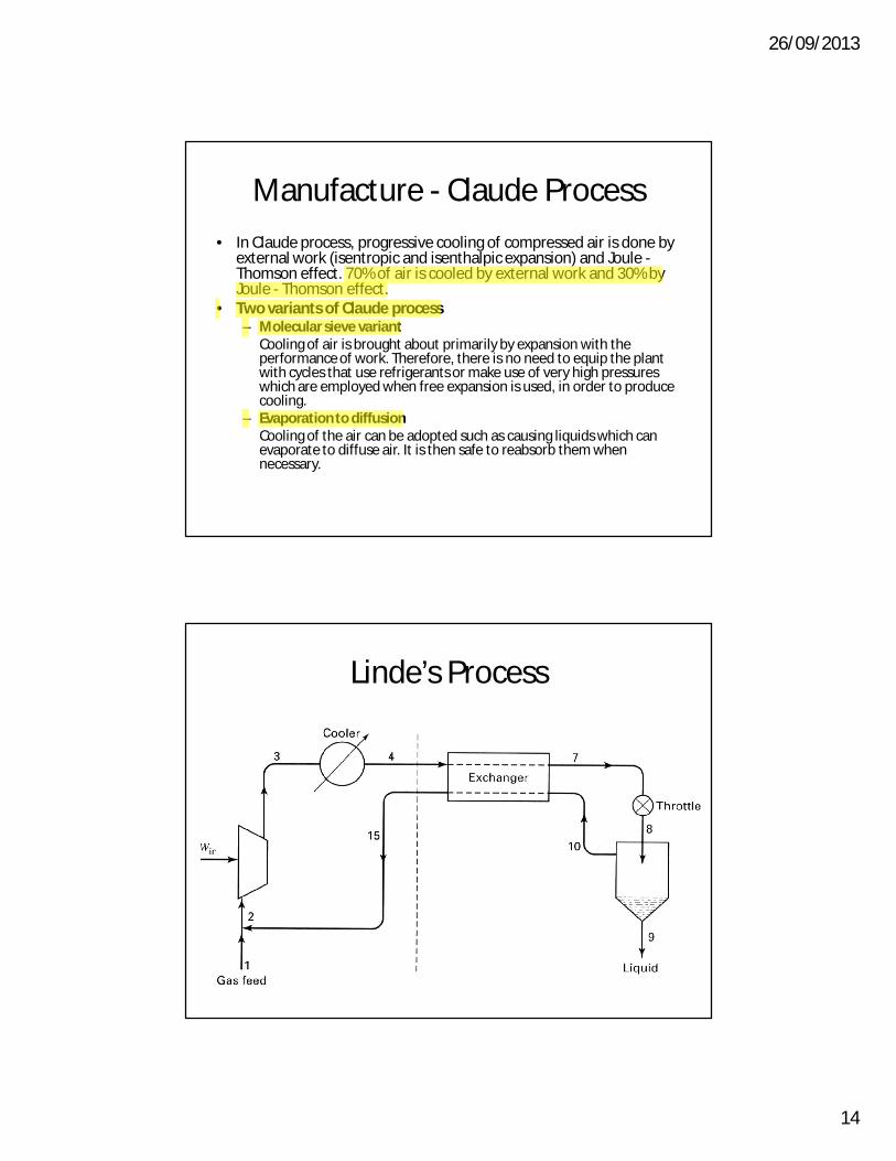
Manufacture - Claude Process
• In Claude process, progressive cooling of compressed air is done by external work (isentropic and isenthalpic expansion) and Joule -Thomson effect. 70% of air is cooled by external work and 30% by Joule - Thomson effect.
• Two variants of Claude process – Molecular sieve variant
Cooling of air is brought about primarily by expansion with the performance of work. Therefore, there is no need to equip the plant with cycles that use refrigerants or make use of very high pressures which are employed when free expansion is used, in order to produce cooling.
– Evaporation to diffusion Cooling of the air can be adopted such as causing liquids which can evaporate to diffuse air. It is then safe to reabsorb them when necessary.
Linde’s Process
Abdul Samad
Highlight
Abdul Samad
Highlight
Abdul Samad
Highlight

26/09/2013
15
Claude’s Process
Manufacture
a) Water wash cooler; b) Reversing heat exchanger; c) Expansion turbine; d) Double column rectifier; e) Condenser; f) Subcooler; g) Adsorber; h) Compressor; i) Filter
Abdul Samad
Highlight

26/09/2013
16
Manufacture - Claude Process
– Kinetics and thermodynamics Liquefied air is subjected to rectification to separate the oxygen and nitrogen components present in it. In liquid state both are miscible in all ratios and they do not form azeotropic mixtures; so they could not separate by boiling the solution.
• Rectification is carried out in a 'plate column', inside which repeated condensations and evaporations take place on plates, which lead to a continuous change in the composition of the binary system throughout the length of the column.
• This is continued until one of its pure components exists at top of the column and the other at the bottom of the column.
Manufacture - Claude ProcessOperation of a rectification column• Pn is the reference plate having
temperature Tn and liquid composition L, vapourcomposition V.
• As pressure is released the more volatile component i. e. N2 is evaporated out partly and goes to the upper plate Pn+1.
• The composition of liquid L2 is having less concentration of N2 at temperature Tn-1.
• Similarly liquid below the reference plate is Pn-1 has higher concentration of O2 and vapourV1 having higher composition of O2 at temperature Tn+1.
The liquids which fall down from the plates toward the heater in the base of the column (L2, L, L1) become progressively richer in the less volatile component (oxygen)
The vapours which rise toward the top of the column (V1, V, V2) gradually become enriched in the more volatile component (nitrogen)

26/09/2013
17
Manufacture - Claude Process
• For, perfect operation of a rectification column always requires that: – The liquid should always be introduced onto a
plate which supports a liquid of the same composition as that of the feedstock liquid
– Part of the distillate from the top of the column is recycled in the form of a 'reflux' with the aim of repeated washing on all of the plates which refine the vapors moving towards the top of the column
Manufacture - Claude Process
• Two-section fractionating tower – Economically acceptable solution– The upper column (rectification column) is about twice the
height of the lower column (enrichment), and both of them are fitted with plates spaced at specific intervals
– Lower column has a boiler. no condenser at the top– Lower column operate at 6 atm– Upper column operates only slightly above atmospheric
pressure – The heat exchanger between the two columns acts as a
condenser with respect to the lower column and a boilerwith respect to the upper column precisely as a result of the two different pressures in the two compartments.
Abdul Samad
Highlight
Abdul Samad
Highlight

26/09/2013
18
Adsorptive Separation
• Nitrogen production by pressure-swing adsorption (PSA) employs carbon molecular sieves.
• The feed air is compressed to 5 – 12 bar, passed through a water-cooled heat exchanger and a condensate separator, and then fed to the adsorbers , which alternate between adsorption and regeneration.
• Water, carbon dioxide and oxygen are removed by adsorption on carbon molecular sieves.
Adsorptive Separation
• The unadsorbed nitrogen leaves the adsorber during the adsorption phase, goes to a buffer vessel at 4 – 11 bar (i.e., ca. 1 bar below the selected inlet pressure) and is delivered from the vessel.
• At the same time, the second adsorber is being regenerated by pressure reduction.
• In principle, the pressure level during the adsorption and regeneration phase can also be lowered; the compressor is replaced by a blower, and a vacuum pump is used to reduce the pressure for regeneration.
Abdul Samad
Highlight
Abdul Samad
Highlight
Abdul Samad
Highlight
Abdul Samad
Highlight
Abdul Samad
Highlight
Abdul Samad
Highlight
Abdul Samad
Highlight

26/09/2013
19
Adsorptive Separation
Schematic of a PSA plant for the production ofnitrogen from air on carbon molecular sievea) Compressor; b) Heat exchanger; c) Condensate separator; d1), d2) Adsorbers; e) Buffer vessel
Adsorptive Separation
• Compressed air enters the adsorption bed at high pressure.
• Typical adsorbents are usually based on zeolites.
• Nitrogen is adsorbed to an appreciably greater extent and oxygen-enriched air is obtained at the outlet.
• The bed is then blown down to a lower pressure to desorb nitrogen.
• A purge step may sometimes be used to sweep nitrogen out of the bed before a new cycle begins
Abdul Samad
Highlight
Abdul Samad
Highlight

26/09/2013
20
Membrane separation
• Nitrogen containing less than 10 ppm by volume of oxygen can be produced economically by using a membrane/Deoxo hybrid system; oxygen is removed by reducing it to water over a catalyst with hydrogen.
• The gas leaving the catalyst bed is cooled, dried, and delivered as product.
bulk liquid / PSA membrane + deoxo / liquid assist cryogenic
Abdul Samad
Highlight
Abdul Samad
Highlight
Abdul Samad
Highlight
Abdul Samad
Highlight
Abdul Samad
Highlight
Abdul Samad
Highlight


