Owner’sMawith Installation Instructionsnual - Banks...
28
9/14/12 PN 96450 v.9.0 Banks Six-Gun ® Diesel Tuner For use with Six-Gun switch 2003-06 Ford Power Stroke 6.0L Turbo-Diesel THIS MANUAL IS FOR USE WITH SYSTEMS 62987 and 62988 Gale Banks Engineering 546 Duggan Avenue • Azusa, CA 91702 (626) 969- 9600 • Fax (626) 334-1743 Product Information & Sales: (888) 635-4565 Customer Support: (888) 839-5600 Installation Support: (888) 839-2700 bankspower.com ©2012 Gale Banks Engineering Owner’sManual with Installation Instructions
Transcript of Owner’sMawith Installation Instructionsnual - Banks...

9/14/12 PN 96450 v.9.0
Banks Six-Gun®
Diesel Tuner For use with Six-Gun switch
2003-06 Ford Power Stroke6.0L Turbo-Diesel THIS MANUAL IS FOR USE WITH SYSTEMS 62987 and 62988
Gale Banks Engineering 546 Duggan Avenue • Azusa, cA 91702 (626) 969-9600 • Fax (626) 334-1743
Product Information & Sales: (888) 635-4565customer Support: (888) 839-5600 Installation Support: (888) 839-2700
bankspower.com
©2012 Gale Banks Engineering
Owner’sManualwith Installation Instructions
2 96450 v.9.0
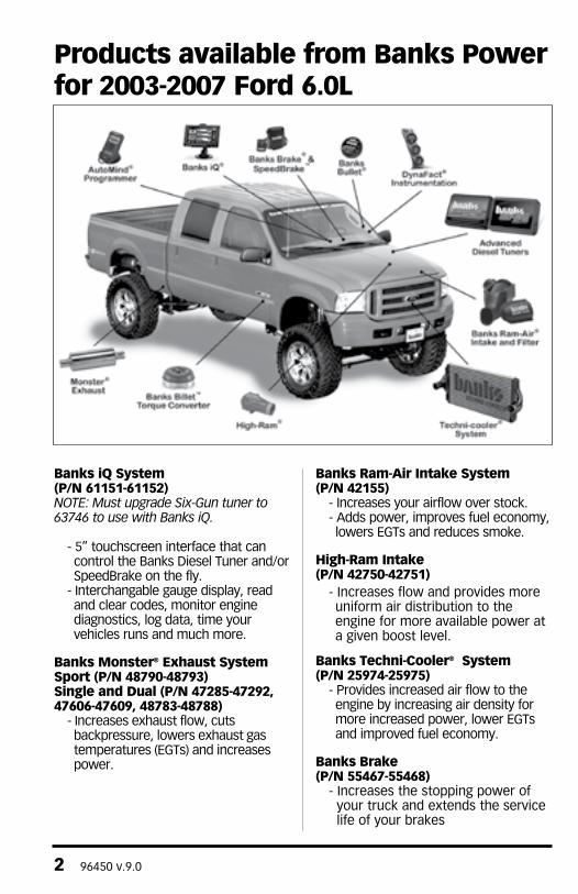
Banks iQ System(P/N 61151-61152)Note: Must upgrade Six-Gun tuner to 63746 to use with Banks iQ.
- 5” touchscreen interface that can control the Banks Diesel Tuner and/or SpeedBrake on the fly.
- Interchangable gauge display, read and clear codes, monitor engine diagnostics, log data, time your vehicles runs and much more.
Banks Monster® Exhaust SystemSport (P/N 48790-48793)Single and Dual (P/N 47285-47292, 47606-47609, 48783-48788)
- Increases exhaust flow, cuts backpressure, lowers exhaust gas temperatures (EGTs) and increases power.
Banks Ram-Air Intake System(P/N 42155)
- Increases your airflow over stock. - Adds power, improves fuel economy, lowers EGTs and reduces smoke.
High-Ram Intake(P/N 42750-42751)
- Increases flow and provides more uniform air distribution to the engine for more available power at a given boost level.
Banks Techni-Cooler® System(P/N 25974-25975)
- Provides increased air flow to the engine by increasing air density for more increased power, lower EGTs and improved fuel economy.
Banks Brake(P/N 55467-55468)
- Increases the stopping power of your truck and extends the service life of your brakes
Products available from Banks Power for 2003-2007 Ford 6.0L

96450 v.9.0 3
For More Information please call (888) 635-4565or Visit us online @ www.bankspower.com
Boost and Pyro Gauges(P/N 64507)
- Keep your engine safe by monitoring vital engine parameters
Banks Billet Torque Converter(P/N 72522)
- Higher torque capacity over stock- Lockup clutch is slip-resistant so
transmission fluids stay cooler and transmission life is prolonged.
Banks SpeedBrakeiQ Compatible (P/N 55455-55456)PDA Compatible (P/N 55457-55458)
- Allows for controlled hill decent at a user defined vehicle speed.
Banks Bullet(P/N 66524-66525)
- Adds power safely to your vehicle - Displays critical engine functions - Engine safeguards - change power levels on-the-fly
Banks Diesel TunerSix-Gun w/ iQ (P/N 63749)EconoMind w/ switch (P/N 63743-63745)EconoMind w/ iQ (P/N 63747-63748)
- Adds power safely to your vehicle
- Engine and transmission safeguards
- change power levels on-the-fly
AutoMind Programmer(P/N 66100)
- contains Banks tunes that boost your vehicles HP, Torque and MPG.
- Displays a host of critical engine functions
- Provides “service technician” diagnostic capabilities
- Has upgradeable functionality, so it will never be out of date
Thermocouple- Add a temperature limiting function to your Diesel Tuner
Banks Stinger Systems(P/N 46465-46486)Contains:
- Ram-Air Intake system- Monster Exhaust (single or dual)- EconoMind Tuner w/ Banks iQ
Banks PowerPack Systems(P/N 46497-46519)Contains:
- Ram-Air Intake system- Monster Exhaust (single or dual)- EconoMind Tuner w/ Banks iQ- High-Ram- Techni-cooler System
Banks Six-Gun Bundle(P/N 46594-46613)Contains:
- Ram-Air Intake system- Monster Exhaust (single or dual)- Six-Gun Tuner w/ Banks iQ
Banks Big Hoss Bundle(P/N 46623-46643)Contains:
- Ram-Air Intake system- Monster Exhaust (single or dual)- Six-Gun Tuner w/ Banks iQ- Big Head Wastegate Actuator- High-Ram- Techni-cooler System
4 96450 v.9.0
Disclaimer of LiabilityGale Banks Engineering Inc., and its distributors, employees, and dealers (hereafter “SELLER”) shall in no way be responsible for the product’s proper use and service. The BUYER hereby waives all liability claims.
The BUYER acknowledges that he/she is not relying on the SELLER’s skill or judgment to select or furnish goods suitable for any particular purpose and that there are no liabilities which extended beyond the description on the face hereof and the BUYER hereby waives all remedies or liabilities, expressed or implied, arising by law or otherwise, (including without any obligations of the SELLER with respect to fitness, merchantability, and consequential damages) whether or not occasioned by the SELLER’s negligence.
The BUYER is responsible to fully understand the capability and limitations of his/her vehicle according to manufacturer specifications and agrees to hold the SELLER harmless from any damage resulting from the failure to adhere to such specifications.
The SELLER disclaims any warranty and expressly disclaims any liability for personal injury or damages. The BUYER acknowledges and agrees that the disclaimer of any liability for personal injury is a material term for this agreement and the BUYER agrees to indemnify the SELLER and to hold the SELLER harmless from any claim related to the item of the equipment purchased. Under no circumstances will the SELLER be liable for any damages or expenses by reason of the use or sale of any such equipment.
The BUYER is responsible to obey all applicable federal, state, and local laws, statutes, and ordinances when operating his/her vehicle, and the BUYER agrees to hold SELLER harmless from any violation thereof.
The SELLER assumes no liability regarding the improper installation or misapplication of its products. It is the installer’s responsibility to check for proper installation and if in doubt, contact the manufacturer.
The BUYER is solely responsible for all warranty issues from the automotive manufacturer.
Limitation of WarrantyGale Banks Engineering Inc. (hereafter “SELLER”), gives Limited Warranty as to description, quality, merchantability, fitness for any particular purpose, productiveness, or any other matter of SELLER’s product sold herewith. The SELLER shall be in no way responsible for the product’s open use and service and the BUYER hereby waives all rights except those expressly written herein. This Warranty shall not be extended or varied except by written instrument signed by SELLER and BUYER.
THIS IS A HIGH PERFORMANCE PRODUCT. USE AT YOUR OWN RISK.Do not use this product until you have carefully read the following agreement.
This sets forth the terms and conditions for the use of this product. The installation of this product indicates that the BUYER has read and understands this agreement and accepts its terms and conditions.
Disclaimer of Liability & Warranty
96450 v.9.0 5
Please see enclosed warranty information card, or go to www.bankspower.com/warranty, for warranty information regarding your product. All products that are in question of Warranty must be returned shipping prepaid to the SELLER and must be accompanied by a dated proof of purchase receipt. All Warranty claims are subject to approval by Gale Banks Engineering Inc.
Under no circumstance shall the SELLER be liable for any labor charged or travel time incurred in diagnosis for defects, removal, or reinstallation of this product, or any other contingent expense.
Under no circumstances will the SELLER be liable for any damage or expenses incurred by reason of the use or sale of any such equipment.
IN THE EvENT THAT THE BUYER DOES NOT AGREE WITH THIS AGREEMENT:The BUYER may promptly return this product, in a new and unused condition, with a dated proof-of-purchase, to the place-of-purchase within thirty (30) days from date-of-purchase for a full refund, less shipping and/or restocking fee.
The installation of this product indicates that the BUYER has read and understands this agreement and accepts its terms and conditions.
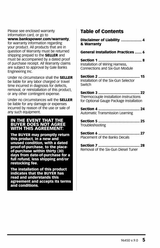
Table of Contents
Disclaimer of Liability ..................... 4 & Warranty
General Installation Practices ....... 6
Section 1 ............................................ 8Installation of Wiring Harness, Connections and Six-Gun Module
Section 2 .......................................... 15Installation of the Six-Gun SelectorSwitch
Section 3 .......................................... 22Thermocouple Installation Instructions for Optional Gauge Package Installation
Section 4 .......................................... 24Automatic Transmission Learning
Section 5 .......................................... 25Troubleshooting
Section 6 .......................................... 27Placement of the Banks Decals
Section 7 .......................................... 28Removal of the Six-Gun Diesel Tuner
6 96450 v.9.0
The Banks Six-Gun Diesel Tuner has six power levels adjustable by the supplied Six-Gun switch. Level 1 is stock. Each additional higher level adds approximately 20% of the available power increase. To prevent damage to the factory transmission, Banks recommends that both automatic and manual transmission vehicles do not exceed Level 4 while the vehicle is experiencing load (towing, climbing a steep grade, carrying a load, etc.).
To use the higher levels of the Six-Gun Diesel Tuner while towing or climbing, airflow improvements must be made to lower the exhaust gas temperature (EGT) entering the turbo. The EGT should not exceed 1400º F for more than a few seconds. Elevated EGT can damage the turbocharger and the engine.
Attention!Before proceeding with these instructions, please carefully read the DISCLAIMER OF LIABILITY and LIMITATION OF WARRANTY statement located on page 4 of this manual.
TOOLS REQUIRED: Six-Gun module• Inch and metric sockets• Inch and metric combination and open-end wrenches• Pliers• Ford stereo removal tool (’03-04 model year vehicles only)• Wire cutters• Scissors• Drill motor• 1⁄8” drill bit• 13⁄32” drill bit
Additional tools required for Thermocouple installation• 7⁄16” drill bit• Tap handle• 1⁄4” NPT tap
Highly recommended tools and supplies for Thermocouple:• Foot-pound torque wrenches• Penetrating oil or light lubricant spray• Anti-seize compound• Heat gun
Dear Customer,
If you have any questions concerning the installation of your Banks Six-Gun Diesel Tuner, please call our Technical Service Hotline at (888) 839-2700 between 7:00am and 5:00pm (PST). If you have any questions relating to shipping or billing, please contact our Customer Service Department at (888) 839-5600.
Thank you.
General Installation Practices

96450 v.9.0 7
1. Before starting work, familiarize yourself with the installation procedure by reading all of the instructions.
2. The exploded views provide only general guidance. Refer to each step and section diagram in this manual for proper instruction.
3. Throughout this manual, the left side of the vehicle refers to the driver side, and the right side to the passenger side.
4. Disconnect the negative (ground) cable from the battery (or batteries, if there are two) before beginning work.
5. Route and tie wires and hoses a minimum of 6” away from exhaust heat, moving parts and sharp edges. clearance of 8” or more is recommended where possible.
6. When raising the vehicle, support it on properly weight-rated safety stands, ramps or a commercial hoist. Follow the manufacturer’s safety precautions. Take care to balance the vehicle to prevent it from slipping or falling. When using ramps, be sure the front wheels are centered squarely on the topsides. When raising the front of the vehicle, put the transmission in park (automatic) or reverse (manual), set the parking brake, and block the rear wheels. When raising the back of the vehicle, be sure the vehicle is on level ground and the front wheels are blocked securely. Caution: Do not use floor jacks to support the vehicle while working under it. Do not raise the vehicle onto concrete blocks, masonry or any other item not intended specifically for this use.
7. During installation, keep the work area clean. Do not allow anything to be dropped into intake, exhaust, or lubrication system components while performing the installation, as foreign objects will cause immediate engine damage upon start-up.
8. Save this Owner’s Manual as a reference for system maintenance and service.
9. Banks recommends that a Pyrometer (EGT) gauge and Boost gauge be installed with the Six-Gun Diesel Tuner to help monitor performance and exhaust gas temperature of the vehicle (see part numbers on pages 2-3). To further increase engine life by lower EGT’s, Banks also recommends installing a Monster Exhaust® system (see pages 2-3).
8 96450 v.9.0
1. Disconnect the battery ground cables from each of the batteries. Secure the cables so that they do not come in contact with the battery posts during the installation.
2. Remove the (+) battery cable from the driver side battery.
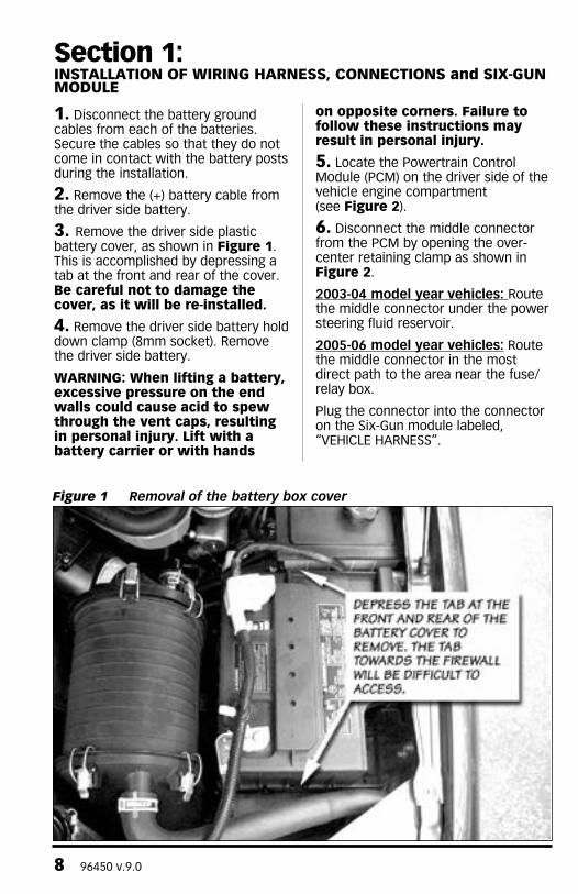
3. Remove the driver side plastic battery cover, as shown in Figure 1. This is accomplished by depressing a tab at the front and rear of the cover. Be careful not to damage the cover, as it will be re-installed.
4. Remove the driver side battery hold down clamp (8mm socket). Remove the driver side battery.
WARNING: When lifting a battery, excessive pressure on the end walls could cause acid to spew through the vent caps, resulting in personal injury. Lift with a battery carrier or with hands
on opposite corners. Failure to follow these instructions may result in personal injury.
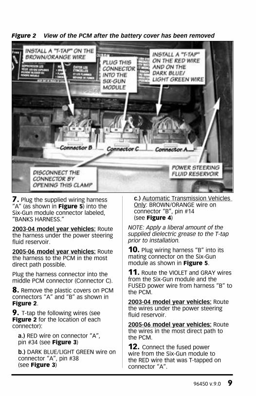
5. Locate the Powertrain control Module (PcM) on the driver side of the vehicle engine compartment (see Figure 2).
6. Disconnect the middle connector from the PcM by opening the over-center retaining clamp as shown in Figure 2.
2003-04 model year vehicles: Route the middle connector under the power steering fluid reservoir.
2005-06 model year vehicles: Route the middle connector in the most direct path to the area near the fuse/relay box.
Plug the connector into the connector on the Six-Gun module labeled, “VEHIcLE HARNESS”.
Section 1:INSTALLATION OF WIRING HARNESS, CONNECTIONS and SIx-GUN MODULE
Figure 1 Removal of the battery box cover
96450 v.9.0 9
7. Plug the supplied wiring harness “A” (as shown in Figure 5) into the Six-Gun module connector labeled, “BANKS HARNESS.”
2003-04 model year vehicles: Route the harness under the power steering fluid reservoir.
2005-06 model year vehicles: Route the harness to the PcM in the most direct path possible.
Plug the harness connector into the middle PcM connector (connector c).
8. Remove the plastic covers on PcM connectors “A” and “B” as shown in Figure 2.
9. T-tap the following wires (see Figure 2 for the location of each connector):
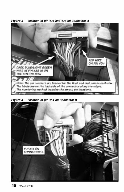
a.) RED wire on connector “A”, pin #34 (see Figure 3)
b.) DARK BLUE/LIGHT GREEN wire on connector “A”, pin #38 (see Figure 3)
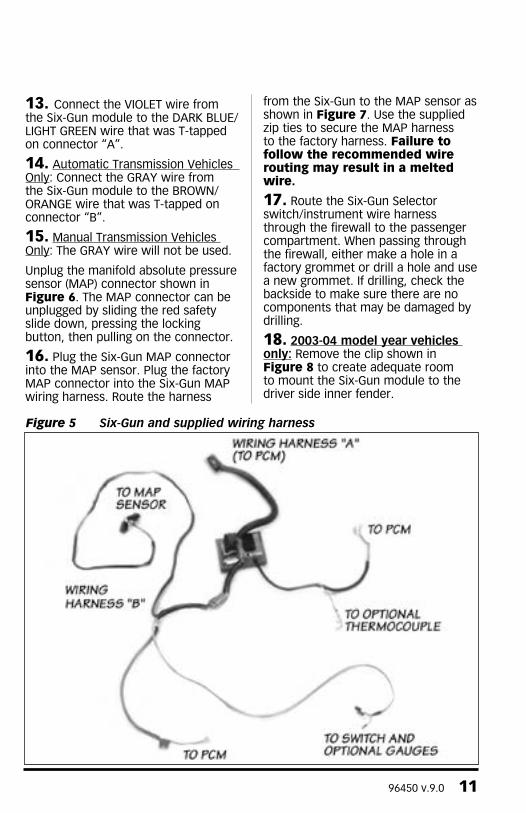
c.) Automatic Transmission Vehicles Only: BROWN/ORANGE wire on connector “B”, pin #14 (see Figure 4)
Note: Apply a liberal amount of the supplied dielectric grease to the t-tap prior to installation.
10. Plug wiring harness “B” into its mating connector on the Six-Gun module as shown in Figure 5.
11. Route the VIOLET and GRAY wires from the Six-Gun module and the FUSED power wire from harness “B” to the PcM.
2003-04 model year vehicles: Route the wires under the power steering fluid reservoir.
2005-06 model year vehicles: Route the wires in the most direct path to the PcM.
12. connect the fused power wire from the Six-Gun module to the RED wire that was T-tapped on connector “A”.
Figure 2 View of the PCM after the battery cover has been removed
10 96450 v.9.0
Figure 3 Location of pin #34 and #38 on Connector A
Figure 4 Location of pin #14 on Connector B
96450 v.9.0 11
13. connect the VIOLET wire from the Six-Gun module to the DARK BLUE/LIGHT GREEN wire that was T-tapped on connector “A”.
14. Automatic Transmission Vehicles Only: connect the GRAY wire from the Six-Gun module to the BROWN/ORANGE wire that was T-tapped on connector “B”.
15. Manual Transmission Vehicles Only: The GRAY wire will not be used.
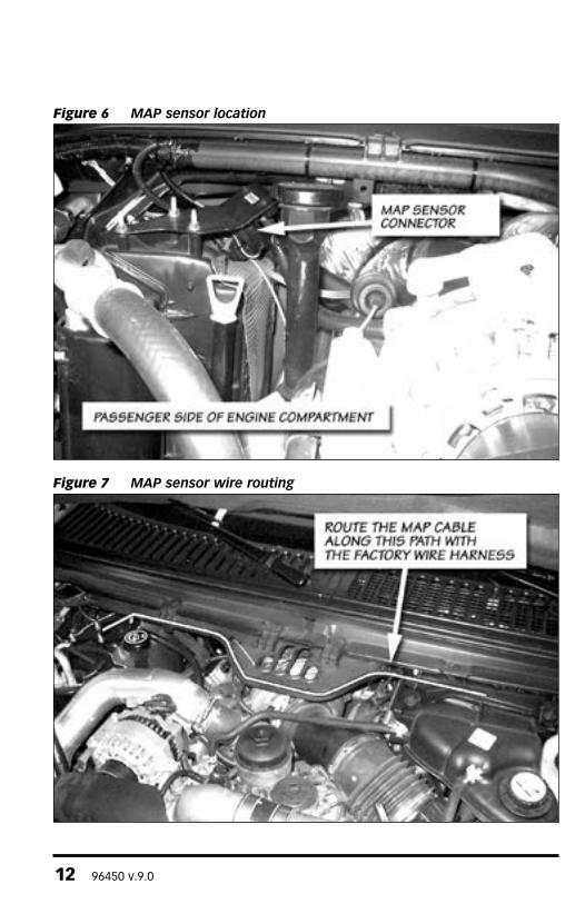
Unplug the manifold absolute pressure sensor (MAP) connector shown in Figure 6. The MAP connector can be unplugged by sliding the red safety slide down, pressing the locking button, then pulling on the connector.
16. Plug the Six-Gun MAP connector into the MAP sensor. Plug the factory MAP connector into the Six-Gun MAP wiring harness. Route the harness
from the Six-Gun to the MAP sensor as shown in Figure 7. Use the supplied zip ties to secure the MAP harness to the factory harness. Failure to follow the recommended wire routing may result in a melted wire.
17. Route the Six-Gun Selector switch/instrument wire harness through the firewall to the passenger compartment. When passing through the firewall, either make a hole in a factory grommet or drill a hole and use a new grommet. If drilling, check the backside to make sure there are no components that may be damaged by drilling.
18. 2003-04 model year vehicles only: Remove the clip shown in Figure 8 to create adequate room to mount the Six-Gun module to the driver side inner fender.
Figure 5 Six-Gun and supplied wiring harness
12 96450 v.9.0
Figure 6 MAP sensor location
Figure 7 MAP sensor wire routing

96450 v.9.0 13
Figure 8 Removal of hood latch cable clip (2003-04 model year vehicles only)
Figure 9 Electronics module to relocate on 4-wheel-drive vehicles (2003-04 model year vehicles only)
19. 2003-04 model year vehicles only: The module shown in Figure 9 will appear only in four-wheel-drive vehicles. This may need to be relocated as shown in Figure 9 to make room for the Six-Gun module. The mounting location of this module by the factory has not been consistent on early vehicles.
20. 2003-04 model year vehicles: The Six-Gun module will be mounted to the inner driver side fender, behind the power steering fluid reservoir.
2005-06 model year vehicles: The Six-Gun module will be mounted on top of the fuse and relay box near the inner drivers side fender.
14 96450 v.9.0
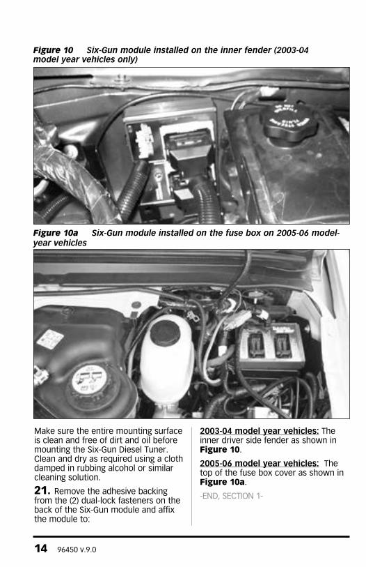
Figure 10 Six-Gun module installed on the inner fender (2003-04 model year vehicles only)
Figure 10a Six-Gun module installed on the fuse box on 2005-06 model-year vehicles
Make sure the entire mounting surface is clean and free of dirt and oil before mounting the Six-Gun Diesel Tuner. clean and dry as required using a cloth damped in rubbing alcohol or similar cleaning solution.
21. Remove the adhesive backing from the (2) dual-lock fasteners on the back of the Six-Gun module and affix the module to:
2003-04 model year vehicles: The inner driver side fender as shown in Figure 10.
2005-06 model year vehicles: The top of the fuse box cover as shown in Figure 10a.
-EnD, SECTIon 1-
96450 v.9.0 15
Section 2:INSTALLATION OF THE SIx-GUN SELECTOR SWITCH
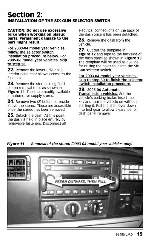
Figure 11 Removal of the stereo (2003-04 model year vehicles only)
CAUTION: Do not use excessive force when working on plastic parts. Permanent damage to the part might result
For 2003-04 model year vehicles, follow the selector switch installation procedure below. For 2005-06 model year vehicles, skip to step 28.
22. Remove the lower driver side interior panel that allows access to the fuse box.
23. Remove the stereo using Ford stereo removal tools as shown in Figure 11. These are readily available at automotive supply stores.
24. Remove two (2) bolts that reside above the stereo. These are accessible once the stereo has been removed.
25. Detach the dash. At this point the dash is held in place entirely by removable fasteners. Disconnect all
electrical connections on the back of the dash once it has been detached.
26. Remove the dash from the vehicle.
27. cut out the template in Figure 12 and tape to the backside of the dash panel as shown in Figure 13. The template will be used as a guide for drilling the holes to locate the Six-Gun selector switch.
For 2003-04 model year vehicles, skip to step 30 to finish the selector switch installation procedure.
28. 2005-06 Automatic Transmission vehicles: Set the vehicle’s parking brake. Insert the key and turn the vehicle on without starting it. Pull the shift lever down into first gear to allow clearance for dash panel removal.
16 96450 v.9.0
All 2005-06 vehicles: Pull the plastic trim surrounding the instrument panel and radio / climate controls towards you until it releases from the main dashboard — it is attached by a series of spring clips around its perimeter. Disconnect all electrical connectors from the back of the dash trim and remove it from the vehicle.
29. cut out the template in Figure 12a and tape it to the front of the dash panel as show in Figure 13a. The template will be used as a guide for drilling holes to locate the Six-Gun selector switch.
30. All model years: Using a 13⁄32” Uni-drill, center the bit onto the 13⁄32” drill location on the template and slowly drill through. Using a 1⁄8” drill bit, center and drill through the 1⁄8” location on the template. Remove and discard the template and any plastic shavings. De-burr the drilled holes as needed to ensure that the Six-Gun selector switch fits squarely against the dash panel.
31. Remove the nut and internal tooth washer from the Six-Gun switch and test fit the switch into the drilled holes. Ensure that the alignment pin properly fits in the 1⁄8” hole. Enlarge the holes as necessary to allow the switch to properly fit. Do not fasten the switch to the dash panel yet.
32. Align the Banks Six-Gun label on the previously drilled hole on the front of the dash panel. Make sure the entire mounting surface is clean and free of dirt and oil before mounting the label. clean and dry as required using a cloth damped with rubbing alcohol of similar cleaning solution. Remove the adhesive backing and affix the label to the dash panel. Hold the label against the panel for approximately 20 seconds while applying pressure to allow the adhesive to properly adhere to the surface.
33. Rotate the switch counter-clockwise until the shaft stops. Verify that the washer tab is inserted into the #6 position on the switch as shown in Figure 14.
Note: All of the power settings may not be usable if the tab is not in slot #6.
34. Install the switch through the 13⁄32” hole on the backside of the bezel. The alignment pin should rest in the 1⁄8” hole and the switch fully rotated counterclockwise. Secure the switch with the internal tooth washer and nut. Snug the nut. Be careful not to over-torque the nut and damage the threads.
35. Install the knob on the shaft facing the #1 Level on the Six-Gun label. on the knob, snug the two (2) set screws with the supplied 0.050” hex key wrench. The completed switch installation will appear as shown in Figure 15.
36. Re-install the dash panel, make all electrical connections that were disconnected, and re-install the radio (2003-04 model year vehicles only).
37. Route the Six-Gun switch’s cable to the wire harness that was routed into the passenger compartment from the Six-Gun module, and plug the 2-pin connector into the corresponding connector on the Six-Gun harness.
Note: the 6-pin plug on the wire harness routed from the Six-Gun module to the passenger compartment will not be used.
38. Reinstall the lower interior panel that allows access to the fuse box (2003-04 vehicles only), the battery cover and battery cables.

96450 v.9.0 17
13/32" DrillLocation
1/8" DrillLocation
Align Edge with Bottomof the Dash Panel
Align Edge with Topof the Dash Panel
2005 Ford 6.0L ONLY
Figure 12 Templates for locating the Six-Gun switch on the dash panel.
2003-04 model year vehicles only
2005-06 model year vehicles only
2005-06 Ford 6.0L ONLY

18 96450 v.9.0
This page left blank intentionally
96450 v.9.0 19
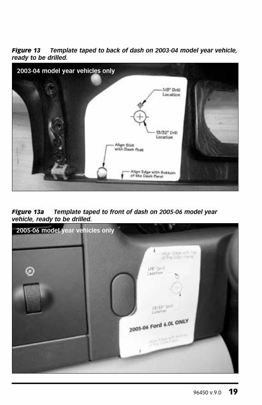
Figure 13 Template taped to back of dash on 2003-04 model year vehicle, ready to be drilled.
2003-04 model year vehicles only
Figure 13a Template taped to front of dash on 2005-06 model year vehicle, ready to be drilled.
2005-06 model year vehicles only

20 96450 v.9.0
-EnD, SECTIon 2-
Figure 14 Six-Gun switch, orientation of the tab on the washer

96450 v.9.0 21
Figure 15 Finished installation of the Six-Gun switch on 2003-04 model year vehicles
Figure 15a Finished installation of the Six-Gun switch on 2005-06 model year vehicle

22 96450 v.9.0
1. The thermocouple monitors the temperature of the exhaust gases entering the turbocharger at the turbine housing. Installation requires that the exhaust manifold be drilled near the manifold outlet. It is recommended that the manifold be removed from the engine to thoroughly clean out all metal chips from drilling. All metal shavings must be cleaned from the manifold to avoid turbine wheel damage and possible interference with the turbochargers variable geometry turbine stage.
2. Disconnect the Exhaust Back Pressure Sensor tap located at the front of the driver side manifold. The pressure tap must be removed by using a 9⁄16” open-end wrench to hold the fitting stationary, and loosen the tube using a 5⁄8” open-end wrench. The fitting is shown in Figure 16.
Note: Failure to hold the fitting stationary will damage the tube upon removal.
3. Remove the driver side exhaust manifold.
4. Drill a 7⁄16” hole in the driver side exhaust manifold at the location shown in Figure 17.
5. Tap the hole for a 1⁄4” NPT thread. check the thread depth as you tap by periodically removing the tap and screwing the pipe coupling into the tapped hole. The coupling should thread in 3 to 31⁄2 turns hand tight. Do not install the probe in place at this time. caution: Running the tap too deeply can prevent the pipe fitting from properly sealing.
6. Remove the NPT fitting from the pyrometer and install it on the exhaust manifold. Use anti-seize lubricant on the threads and torque to 14–16 lb-ft.
7. Remove all metal chips from the exhaust manifold.
Note: Failure to remove all metal chips could result in catastrophic damage to the turbocharger’s turbine wheel or interfere with the operation of the variable geometry vane mechanism.
8. Re-install the exhaust manifold. Apply anti-seize lubricant to the manifold bolt threads and torque to 28 lb-ft. Use the tightening sequence shown in Figure 18.
9. Tighten the turbocharger adapter pipe fasteners to 20 lb-ft as shown in Figure 19.
Section 3:THERMOCOUPLE INSTALLATION INSTRUCTIONS FOR OPTIONAL GAUGE PACKAGE INSTALLATION
Figure 16 Location of the static exhaust pressure line tap

96450 v.9.0 23
10. Reconnect the exhaust backpressure static line tube.
11. Connect the sensor wire to the Six-Gun module with the supplied screws. The yellow sensor wire attaches to the free yellow wire on the Six-Gun module. The red sensor wire attaches to the free red wire on the Six-Gun module.
12. Slide the heat shrink over the exposed metal junction, and supply moderate heat to seal the connection. A heat gun works well.
13. Route the pyrometer to the exhaust manifold and install the DynaFact pyrometer probe in the fitting.
-EnD, SECTIon 3-
Figure 17 Location to drill and tap the driver side exhaust manifold for the DynaFact pyrometer sensor
Figure 18 Exhaust manifold tightening sequence
Figure 19 Turbocharger adapter pipe torque specification

24 96450 v.9.0
Section 4:AUTOMATIC TRANSMISSION LEARNING
The 6.0L Ford Trucks equipped with the TorqShiftTM 5-speed automatic overdrive transmission use an adaptive shift control logic. This will require the transmission to learn how to cope with the additional power created by the Banks Power products before it will shift properly. Additionally, the Banks Six-Gun Diesel Tuner will require a short learning curve to characterize the transmission in order to optimize fueling during gear change events. The following sequence must be followed to allow for collaborative learning between the Banks Six-Gun and the transmission’s control system. Failure to follow the sequence can result in damage to the transmission.
Perform the following sequence at a location where it is safe to accelerate to 60 mph without exceeding the posted speed limit.
1. Start the truck and allow the engine to reach normal operating temperature.
2. Turn the Six-Gun selector switch to the #2 position.
3. Accelerate with the pedal to the floor, from a standing start to 60 mph. Repeat three (3) times.
4. Cruise at 30 mph, then press the accelerator to the floor to cause the transmission to downshift. continue accelerating to 60 mph.
5. Repeat steps 3 and 4 for the next power setting.
6. continue to increase the power setting and drive cycle until the desired power setting is achieved.
The TorqShift™ 5-speed automatic transmission will continually adapt to the power output of the engine to optimize shift quality. This will result in the transmission un-learning how to cope with the higher power settings of the Six-Gun Diesel Tuner, if the selector switch is returned to a lower power setting. The rate that the transmission un-learns how to cope with the higher power levels, when switching to a lower power level, depends on the driving cycle. The transmission will quickly adapt to the power setting if the driving cycle includes regular gear changes at high loads. The transmission learning procedure will need to be repeated when switching back to the higher power settings once the transmission adapts to the lower power settings. It will be apparent when the transmission adapts to the lower settings by monitoring the feel of the gearshift. Gear changes will be noticeably harder when initially switching from a higher to lower power setting. This will soften as the transmission adapts to the new setting.
For example: If the transmission has adapted to level 3 and it is desired to go to level 6, the transmission learning procedure can start at level 3.
IF TRANSMISSION SLIP IS DETECTED DURING THE TRANSMISSION LEARN PROCESS, REDUCE THE POWER LEVEL BY ONE, AND START OVER AT STEP 3.
-EnD, SECTIon 4-
96450 v.9.0 25
Section 5:TROUBLESHOOTING
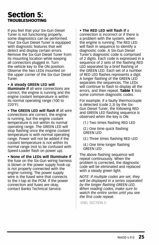
If you feel that your Six-Gun Diesel Tuner is not functioning properly, some diagnostics can be performed. Your Six-Gun Diesel Tuner is equipped with diagnostic features that will detect and display certain errors. Remove the Six-Gun Diesel Tuner from its mounting location while keeping all connectors plugged in. Turn the vehicle key to the ON position. Observe the two LEDs mounted on the upper corner of the Six-Gun Diesel Tuner.
• A steady GREEN LED will illuminate if all wire connections are correct, the engine is running and the engine coolant temperature is within its normal operating range (100 to 220°F).
• The GREEN LED will flash if all wire connections are correct, the engine is running, but the engine coolant temperature is not within its normal operating range. The GREEN LED will stop flashing once the engine coolant temperature is with normal operating range. Power will not be added if the coolant temperature is not within its normal range (not to be confused with Speed-Loader flash on power up).
• None of the LEDs will illuminate if the fuse on the Six-Gun wiring harness is blown or the power supply hook-up is not properly connected with the engine running. The power supply wire is the fused wire that connects to the t-tap at the PcM. If the power connection and fuses are okay, contact Banks Technical Service.
• The RED LED will flash if a connection is incorrect or if there is a problem with the system, when the engine is running. The RED LED will flash in sequence to identify a diagnostic code. A Six-Gun Diesel Tuner’s diagnostic code is comprised of 2 digits. Each code is expressed in a sequence of 2 sets of the flashing RED LED separated by a brief flashing of the GREEN LED. Each set of a number of RED LED flashes represents a digit. A longer flashing of the GREEN LED separates the sequences. The LEDs will continue to flash to display all the errors, and then repeat. Table 1 lists some common diagnostic codes.
For example, if a faulty thermocouple is detected (code 2,3) by the Six-Gun Diesel Tuner, the following RED and GREEN LED flashing sequence is observed when the key is ON:
(1.) Two times flashing RED LED
(2.) One time quick flashing GREEN LED
(3.) Three times flashing RED LED
(4.) One time longer flashing GREEN LED
The above flashing sequence will repeat continuously. When the problem is corrected, the diagnostic code will be eliminated and replaced with a steady green light.
Note: If multiple codes are set, they will be displayed in a series separated by the longer flashing GreeN LeD. When reading codes, make sure to watch the entire series until you see the first code repeat.
-EnD, SECTIon 5-
26 96450 v.9.0
DIAGNOSTIC
CODECODE DESCRIPTION COURSE OF ACTION
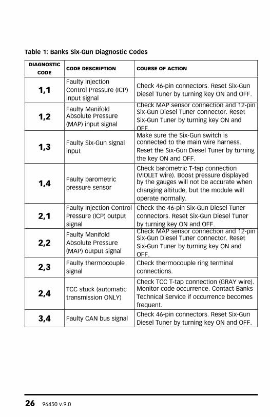
1,1Faulty Injection control Pressure (IcP) input signal
Check 46-pin connectors. Reset Six-Gun Diesel Tuner by turning key ON and OFF.
1,2Faulty Manifold Absolute Pressure (MAP) input signal
check MAP sensor connection and 12-pin Six-Gun Diesel Tuner connector. Reset Six-Gun Tuner by turning key ON and OFF.
1,3 Faulty Six-Gun signal input
Make sure the Six-Gun switch is connected to the main wire harness. Reset the Six-Gun Diesel Tuner by turning the key ON and OFF.
1,4 Faulty barometric pressure sensor
check barometric T-tap connection (VIOLET wire). Boost pressure displayed by the gauges will not be accurate when changing altitude, but the module will operate normally.
2,1Faulty Injection control Pressure (IcP) output signal
Check the 46-pin Six-Gun Diesel Tuner connectors. Reset Six-Gun Diesel Tuner by turning key ON and OFF.
2,2Faulty Manifold Absolute Pressure (MAP) output signal
check MAP sensor connection and 12-pin Six-Gun Diesel Tuner connector. Reset Six-Gun Tuner by turning key ON and OFF.
2,3 Faulty thermocouple signal
check thermocouple ring terminal connections.
2,4 Tcc stuck (automatic transmission ONLY)
check Tcc T-tap connection (GRAY wire). Monitor code occurrence. contact Banks Technical Service if occurrence becomes frequent.
3,4 Faulty cAN bus signalCheck 46-pin connectors. Reset Six-Gun Diesel Tuner by turning key ON and OFF.
Table 1: Banks Six-Gun Diagnostic Codes
96450 v.9.0 27
Table 1: Banks Six-Gun Diagnostic Codes
Section 6:PLACEMENT OF THE BANKS POWER DECALS
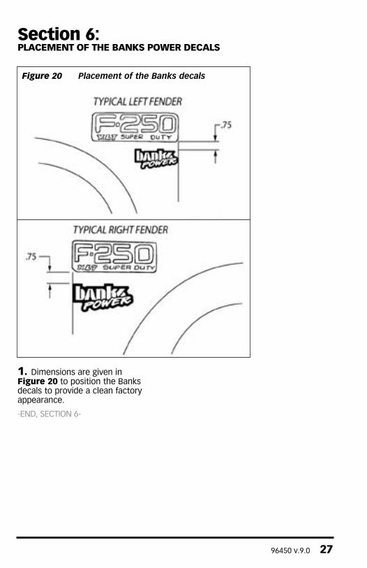
Figure 20 Placement of the Banks decals
1. Dimensions are given in Figure 20 to position the Banks decals to provide a clean factory appearance.
-EnD, SECTIon 6-
Section 7:REMOvAL OF THE SIx-GUN DIESEL TUNER
1. If the Six-Gun Diesel Tuner should ever need to be removed from the vehicle, perform the following:
1.) Disconnect the Six-Gun’s 46-pin connector (connector c) from the middle connection on the PcM.
2.) Re-connect the vehicle’s 46-pin connector back into the middle connection on the PcM.
3.) Disconnect the GRAY and VIOLET wires from the T-taps on the PcM’s “A” and “B” connectors (the Six-Gun’s fused power wire does not need to be removed).
4.) Disconnect the Six-Gun’s MAP connections from the vehicles MAP sensor and harness. Re-connect the vehicle’s MAP connector back into the MAP sensor.
5.) Disconnect the 2-ring terminals from the EGT probe.
6.) Disconnect the Six-Gun’s 12-pin harness connector (harness “B” shown in Figure 5).
7.) Remove the Six-Gun module.
Failure to follow the above instructions when removing the module will result in a “check Engine” light on the dash and a Diagnostic Trouble code being stored in the factory computer, in addition to the engine not running.
-EnD, SECTIon 7-
Gale Banks Engineering 546 Duggan Avenue • Azusa, cA 91702 (626) 969-9600 • Fax (626) 334-1743
Product Information & Sales: (888) 635-4565customer Support: (888) 839-5600 Installation Support: (888) 839-2700
bankspower.com