Owner's Manual/ManualDelPr0pietari0 CRAFTSMAN3. Placethe motor unit on packing material to protect...
76
Owner's Manual/ManualDel Pr0pietari0 CRAFTSMAN° 112 HP 315MHz GARAGE DOOR OPENER ABRIDOR DE PUERTA DE COCHERA For Residential Use Only/Solo para uso residencial Model/Modelo • 139.53904D DE 315MHz m Z G3 I"11 "0 Z_ 0 Read and follow all safety rules and operating instructions before first use of this product. Fasten the manual near the garage door after installation. Periodic checks of the opener are required to ensure safe operation. Leer y seguir todas las reglas de seguridad y las instrucciones de operacion antes de usar este producto por primera vez. Guardar este manual cerca de la puerta de la cochera. Se deben realizar revisiones periodicas del abridor de puertas para asegurar su operacion segura. 0Qus Sears, Roebuck and Co., Hoffman Estates, IL 60179 U.S.A www.sears.com/craftsman
Transcript of Owner's Manual/ManualDelPr0pietari0 CRAFTSMAN3. Placethe motor unit on packing material to protect...

Owner's Manual/ManualDel Pr0pietari0
CRAFTSMAN°112 HP
315MHz GARAGE DOOR OPENERABRIDOR DE PUERTA DE COCHERAFor Residential Use Only/Solo para uso residencial
Model/Modelo • 139.53904D
DE 315MHz
mZG3
I"11
"0
Z_0
Read and follow all safety rules andoperating instructions before first useof this product.
Fasten the manual near the garagedoor after installation.
Periodic checks of the opener arerequired to ensure safe operation.
Leer y seguir todas las reglas deseguridad y las instrucciones deoperacion antes de usar este productopor primera vez.
Guardar este manual cerca de lapuerta de la cochera.
Se deben realizar revisiones
periodicas del abridor de puertas paraasegurar su operacion segura.
0QusSears, Roebuck and Co., Hoffman Estates, IL 60179 U.S.Awww.sears.com/craftsman

TABLE OF CONTENTS
INTRODUCTION 2- 7
Safety symbol and signal word review ....................................... 2
Preparing your garagedoor ........................................................ 3Tools needed.............................................................................. 3
Planning ..................................................................................4-5
Carton inventory ......................................................................... 6
Hardware inventory..................................................................... 7
ASSEMBLY 8-11
Assemble the rail and install the trolley ...................................... 8Fastenthe rail to the motor unit andInstall the idler pulley.................................................................. 9
Install the belt and attach the belt cap retainer......................... 10Set the tension.......................................................................... 11
INSTALLATION 11-26
Installation safety instructions .................................................. 11Determine the headerbracket location ..................................... 12
Install the headerbracket.......................................................... 13
Attach the rail to the headerbracket......................................... 14
Position the opener................................................................... 15
Hang the opener ....................................................................... 16Install the door control ............................................................. 17
Install the lights ........................................................................ 18
Attach the emergency release rope and handle........................ 18
Electrical requirements ............................................................. 19
Install The Protector System®..............................................20-22Fastenthe door bracket....................................................... 23-24
Connect the door arm to the trolley ..................................... 25-26
ADJUSTMENT 27-29
Adjust the travel limits .............................................................. 27
Adjust the force ........................................................................ 28
Test the safety reversalsystem................................................. 29
Test The Protector System®...................................................... 29
OPERATION 30-34
Operation safety instructions .................................................... 30
Using your garagedoor opener ................................................ 30
Using the wall-mounted Door Control ...................................... 31
To open the door manually ....................................................... 31
Care of your garagedoor opener.............................................. 32
Having a problem?.................................................................... 33
Diagnostic chart ........................................................................ 34
PROGRAMMING 35-36
To add or reprogram a hand-held remote control .................... 35To erase all codes..................................................................... 35
3-Function Remotes.................................................................. 35
To add, reprogram or change a KeylessEntry PIN................... 36
REPAIRPARTS 37-38
Rail assembly parts .................................................................. 37
Installation parts ....................................................................... 37
Motor unit assembly parts ........................................................ 38
ACCESSORIES 39
WARRANTY 39
REPAIRPARTS& SERVICE BACKCOVER
INTRODUCTION
Safely Symboland Signal WordReview
This garage door opener has beendesigned and tested to offer safe service provided it is installed, operated,maintained and tested instrict accordancewith the instructions and warnings contained in this manual.
Mechanical
Electrical
When you see these Safety Symbols and Signal Words on thefollowing pages, they will alert you to the possibility of seriousinjury or death if you do not comply with the warnings thataccompanythem. The hazard may come from somethingmechanical or from electric shock. Readthe warnings carefully.
When you see this Signal Word on the following pages, it willalert you to the possibility of damageto your garagedoor and/orthe garagedoor opener if you do not comply with the cautionarystatements that accompany it. Readthem carefully.
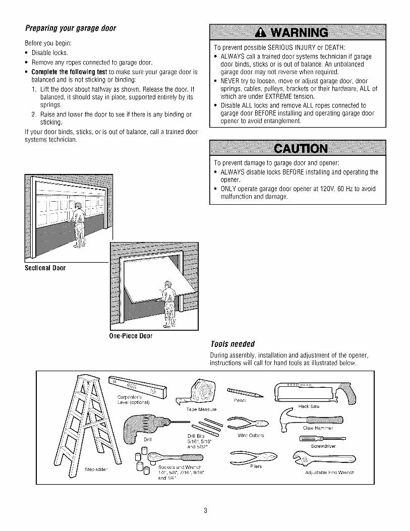
Preparingyourgarage door
Before you begin:* Disable locks.
* Removeany ropes connected to garage door.
° Complete the following test to make sure your garage door isbalanced and is not sticking or binding:
1. Lift the door about halfway as shown. Releasethe door. Ifbalanced, it should stay in place,supported entirely by itssprings.
2. Raiseand lower the door to see if there is any binding orsticking.
If your door binds, sticks, or is out of balance,call a trained doorsystems technician.
To prevent possible SERIOUSINJURYor DEATH:
° ALWAYScall a trained door systems technician if garagedoor binds, sticks or is out of balance.An unbalancedgaragedoor may not reversewhen required.
° NEVERtry to loosen, move or adjust garagedoor, doorsprings, cables, pulleys, brackets or their hardware,ALL ofwhich are under EXTREMEtension.
° DisableALL locks and removeALL ropes connected togaragedoor BEFOREinstalling and operating garagedooropener to avoid entanglement.
To prevent damageto garage door and opener:° ALWAYSdisable locks BEFOREinstalling and operating the
opener.° ONLYoperate garagedoor opener at 120V, 60 Hzto avoid
malfunction and damage.
SectionalDoor
One-Piece DoorTools needed
During assembly, installation and adjustment of the opener,instructions will call for handtools as illustrated below.
Stepladder
Level (optional)Pencil
Tape Measure
Dr_ Wire Cutters
Drill 3/16", 5/16"
_0 and 5/32"
1/2", 5/8", 7/16", 9/16" Pliers
and 1/4"
Hack Saw
Claw Hammer
Screwdriver
Adjustable End Wrench

P_nnmg
Identify the type and height of your garagedoor. Surveyyourgarageareato see if any of the conditions below apply to yourinstallation. Additional materials may be required. You may find ithelpful to refer back to this pageand the accompanyingillustrations as you proceed with the installation of your opener.
Depending on your requirements, there are several installationsteps which may call for materials or hardware not included inthe carton.
• Installation Step 1 - Look at the wall or ceiling above thegaragedoor. The header bracket must be securely fastened tostructural supports.
• Installation Step 5 - Do you have a finished ceiling in yourgarage? If so, a support bracket and additional fasteninghardware may be required.
• Installation Step 10 - Dependingupon garageconstruction,extension brackets or wood blocks may be neededto installsensors
• Installation Step 10 - Alternate floor mounting of the safetyreversingsensor will require hardware not provided.
• Doyou have an access door in addition to the garagedoor? Ifnot, Model 53702 Emergency Key Releaseis required. SeeAccessories page.
• Look at the garage door where it meets the floor. Any gapbetweenthe floor and the bottom of the door must not exceed1/4" (6 mm). Otherwise, the safety reversal system may notwork properly. SeeAdjustment Step 3. Floor or door should berepaired.
SECTIONALDOORINSTALLATIONS
• Doyou have a steel, aluminum, fiberglass or glass panel door?If so, horizontal and vertical reinforcement is required(Installation Step 11).
• The opener should be installed above the center of the door. Ifthere is a torsion spring or center bearing plate in the way ofthe header bracket, it may be installed within 4 feet (1.22 m)to the left or right of the door center. See Installation Steps 1and 11.
• If your door is more than 7 feet (2.13 m) high, see railextension kits listed on Accessories page.
SectionalDoor Installation
Horizontal and vertical reinforcement
is needed for lightweight garage doors(fiberglass, steel, aluminum, door withglass panels, etc.). See page 23 for details.
Header Wail
Rail
Extension SpringOR
FINISHED CEILING
Support bracket &fastening hardware
is required.See page 16.
,tor unit
Wall-mounted [Door Access Door
Control
©
Safety Reversing Sensor
Gap between floorand bottom of door
must not exceed 1/4" (6 mm).
SafetyReversingSensor
CLOSED POSITIONHeader
Bracket Trolley
/ Stop Bolt TrolleyL_ Garage ...... .....
F///,_ Door 'c_/ --I Belt
_////4 Spring I__ _/Str"a?ht L Emergency Release
_/ Arm i_ Rope&Handle
I _ _ CurvedHeader _ _ DoorWall Ix\/I \ Arm
Garage HI £oo:oooJ-1-lJ _ek_

Planning(Continued)
ONE-PIECEDOORINSTALLATIONS
• Generally,a one-piece door does not require reinforcement. Ifyour door is lightweight, refer to the information relating tosectional doors in Installation Step 11.
• Dependingon your door's construction, you may needadditional mounting hardware for the door bracket (Step 11).
Without a properly working safety reversal system, persons(particularly small children) could be SERIOUSLYINJUREDorKILLEDby a closing garagedoor.
• The gap betweenthe bottom of the garage door and thefloor MUST NOTexceed1/4" (6 mm). Otherwise, the safetyreversalsystem may not work properly.
• The floor or the garage door MUST be repairedto eliminatethe gap.
ONE-PIECEDOORWITHOUTTRACKFINISHED CEILING
Support bra(& fasteninghardware is required.See page 16.
rdf'l I
Safety Reversing Sensor
Header Wall
Rail
J
AccessDoor
Safety Reversing
Gap between floor Sensor
Wall-mountedDoor Control
and bottom of door must not exceed 1/4" (6 ram).
Motor Unit
eader,'all
CLOSED POSITION
Trolley Stop BoltBelt Trolley
Straight DoorDoor
ArmArm
-- GarageDoor
EmergencyRelease
Rope & Handle
ONE-PIECEDOORWITH TRACK
Jl__ Gapbteween floor Sensor_._v .-\ and bottom of door
Safety must not exceed 1/4" (6 mm).Reversing Sensor
CLOSED POSITION
Trolley Stop Bolt Belt Trolley
DoorBracket
GarageDoor
StraightDoorArm
Rail
Release
Rope &Handle

CartonInventory
Your garagedoor opener is packagedin one carton whichcontains the motor unit and all parts illustrated below.Accessories will depend on the model purchased. If anything ismissing, carefully check the packing material. Parts may be stuck
in the foam. Hardwarefor assemblyand installation is shown onthe next page. Savethe carton and packing material untilinstallation and adjustment is complete.
Door Control Button
SECURITY+ ®
3-Function Remote Control (1)
Belt Cap RetainerTrolley
Motor Unit with 2 Light Lenses
Idler Pulley
Rail
Fron! (header) /_/,"
y Header Bracket
RailCenter/BackSections
Belt
Door Bracket
Curved DoorArm Section
Hanging Brackets
Safety SensorBracket (2)
The Protector System _(2) Safety Reversing Sensors(1 Sending Eye and 1 Receiving Eye)with 2-Conductor White & White/BlackBell Wire attached
2-Conductor Bell WireWhite & White/Red
Safety Labelsand
Literature Straight DoorArm Section
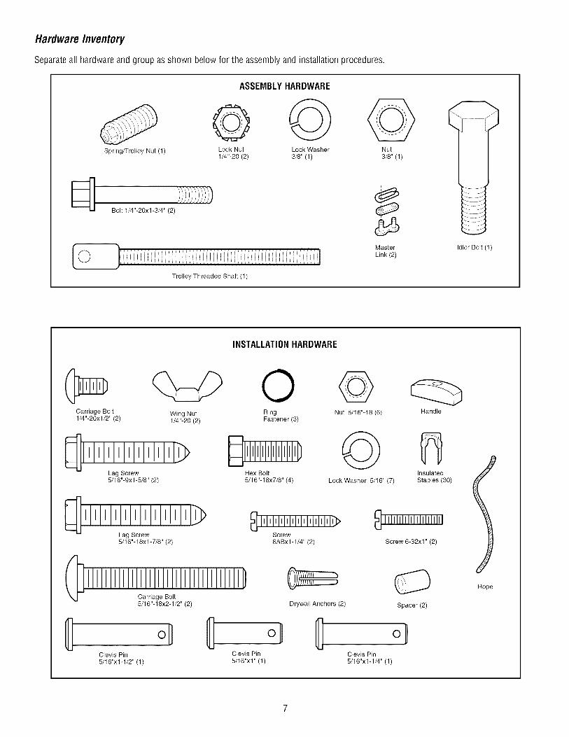
HardwareInventory
Separateall hardware and group as shown below for the assembly and installation procedures.
Spring/Trolley Nut (1)
ASSEMBLYHARDWARE
@Lock Nut
1/4"-20 (2)
ObLock Washer3/8" (1)
Nut
3/8" (1)
Bolt 1/4"-20xl-3/4" (2)
Trolley Threaded Shaft (1)
Master
Link (2)Idler Bolt (1)
INSTALLATIONHARDWARE
Carriage Bolt1/4"-20xl/2" (2)
Wing Nut1/4"-20 (2)
1111111111_Lag Screw5/16"-9xl-5/8" (2)
_1111111111 ilhlhl_Lag Screw5/16"-18xl-7/8" (2)
Carriage Bolt5/16"- 18x2-1/2" (2)
ORingFastener (3)
_,1111111111DHex Bolt
5/16"-18x7/8" (4)
_]IIl'l'l'lllllMIMl'IIlllll_Screw
6ABx1-1/4" (2)
Nut 5/16"-18 (6)
Lock Washer 5/16" (7)
Insulated
Staples (30)
111111111111111111111
Screw 6-32xl" (2)
Drywall Anchors (2)
Clevis Pin Clevis Pin
5/16"x1-1/2" (1) 5/16"x1" (1)
Spacer(2)
oHClevis Pin
5/16"x1-1/4" (1)
Rope

ASSEMBLY STEP 1
Assemble the Raft & Install the Trolley
To avoid installation difficulties, do notrun the garage dooropeneruntil instructedto do so.
To prevent INJURY from pinching, keep hands and fingersaway from the joints while assembling the rail.
The front rail has a cut out "window" at the door end (seeillustration). Thehole abovethis windowis larger onthe top ofthe raft than on the bottom. A smaller hole 3-1/2" (8.9 cm) awayis close to the rail edge. Rotate the back rail so it has a similarhole close to the oppositeedge,about 4-3/4" (12 cm) from the farend.
1. Removethe straight door arm and hanging bracket packagedinside the front rail and set aside for Installation Step 5 and 12.
NOTE:Toprevent INJURY while unpacking the rail carefullyremove the straight door arm stored within the rail section.
2. Align the rail sections on a flat surface as shown and slide thetapered ends into the larger ones. Tabs along the side will lockinto place.
3. Placethe motor unit on packing material to protect the cover,and rest the back end of the rail on top. For convenience,put asupport under the front end of the rail.
4. As a temporary stop, insert a screwdriver into the hole10" (25 cm) from the front end of the rail, as shown.
5. Checkto besure there are 4 plastic wear pads inside the innertrolley. If they becameloose during shipping, check all packingmaterial. Snapthem back into position as shown.
6. Slide the trolley assembly along the rail from the back end tothe screwdriver.
Trolley
End
3eredEnd
Back Rails
(TO MOTOR UNIT)
End
Screwdriver
Tabs
WindowCut-Out
Front Rail !
Idler (TO DOOR)
Hole
End
Inner Trolley _ey__
_ Wear Pads

ASSEMBLY STEP 2
Fastenthe Rail to the MotorUnit
• Insert a 1/4"-20xl-3/4" bolt into the cover protection bolt holeon the back end of the rail as shown. Tighten securely with a1/4"-20 lock nut. Do NOTovertighten.
• Removethe two bolts from the top of the motor unit.• Placethe "U" bracket, flat side down, on the motor unit and
align the bracket holes with the bolt holes. Fastenwith thepreviously removed bolts.
• Align the rail assemblywith the top of the motor unit. Slide therail end onto the "U" bracket,all the way to the stops thatprotrude on the top and sides of the bracket.
To avoid SERIOUSdamage to garagedoor opener, use ONLYthose bolts/fasteners mounted in the top of the opener.
"U" Bracket
Bolt
I
CoverProtection
Bolt Hole X
Bolts
I
Motor Unit
Sprocket
HARDWARESHOWN ACTUALSIZE
Lock Nut
Bolt 1/4"-20xl-3/4" 1/4"-20
t
SLIDE RAIL TO STOPSON TOP AND SIDES
_ OF BRACKETI
Lock Nut
ASSEMBLY STEP 3
Install the Idler Pulley
• Laythe belt beside the rail, as shown. Graspthe end with thehooked trolley connector and pass approximately 12" (30 cm)of belt through the window. Keepthe ribbed side toward therail, and allow it to hang until Assembly Step 5.
• Removethe tape from the idler pulley. The inside center shouldbe pre-greased. If dry, regreaseto ensure proper operation.
• Placethe idler pulley into the window as shown.
• Insert the idler bolt from the top through the rail and pulley.Tighten with a 3/8" lock washer and nut underneaththe railuntil the lock washer is compressed.
• Rotatethe pulley to be sure it spins freely.
• Insert a 1/4"-20xl-3/4" bolt into the trolley stop hole in thefront of the rail as shown. Tighten securely with a 1/4"-20 locknut.
Grease
____ __lnside
Pulley
_ Idler PulleyLock Washer
3/8" -_
I_- Nut 3/8"
TrolleyConnector
Bolt
r (_ Lock
Pulley , Nut
Idler Bolt
HARDWARESHOWN ACTUALSIZE
Bolt 1/4"-20xl-3/4" Lock Nut 1/4"-20 Nut 3/8" Lock Washer 3/8"

ASSEMBLY STEP 4
Insta// the Be/t and Attach the Be/t Cap Retainer
1. Pull the belt around the idler pulley and toward the trolley. Theribbed side must contact the pulley.
2. Hookthe trolley connector into the retaining slot on the trolleyas shown.
3. With the trolley against the screwdriver, dispensetheremainder of the belt along the rail length toward the motorunit and around the sprocket. The sprocket teeth must engagethe belt.
4. Checkto make sure the belt is not twisted and the FLATside ofthe trolley threaded shaft is facing the rail. Connect the trolleythreaded shaft with the master link, as illustrated:
• Push pins of master link bar through holes in end of beltand trolley threaded shaft.
• Push master link cap over pins and past pin notches.
• Slide clip-on spring over cap and onto pin notches until bothpins are securely locked in place.
5. Insert the trolley threaded shaft through the hole in the trolley.Besure the belt is not twisted and the FLAT side of the trolleythreadedshaft faces the rail.
6. Hold the belt at the trolley shaft as you thread the spring nut byhand onto the shaft until finger tight against the trolley. Do notuse any tools.
7. Removethe screwdriver.
8. Position the belt cap retainer over the motor unit sprocket asshown and fasten to the mounting plate with 8x3/8" hex screwsprovided.
To avoid possible SERIOUSINJURYto fingers from movinggaragedoor opener:
• ALWAYS keep hand clear of sprocket while operatingopener.
• Securely attach sprocket cover BEFOREoperating.
HARDWARE SHOWN ACTUAL SIZE
Hex Screw 8x3/8"
Spring/Trolley Nut
Master Link
Clip-On Spring
Master Link Cap
Idler Pulley
Retaining
Trolley SlotConnector
Hole
Pin
Notch ITrolley MasterThreaded Link BarShaft
Hex Screws
Belt Cap__"'_ #8x3/8"
Retainer_Motor Unit
I Sprocket
Plate
10

ASSEMBLY STEP 5
Set the Tension
• Insert a screwdriver tip into one of the nut ring slots and braceit firmly against the trolley.
• Placea 7/16" open end wrench on the square end. Rotate thenut about 1/4 turn until the spring releasesand snaps the nutring against the trolley.
This sets the spring to optimum belt tension.
Youhave nowfinished assemblingyour garage door opener.Please read the following warningsbeforeproceedingto theinstallation section.
SquareEnd Nut Rinc
Trolley
Nut Rin(
INSTALLATION
IMPORTANT INSTALLATION INSTRUCTIONS
To reduce the risk of SEVERE INJURY or DEATH:1. READAND FOLLOWALL INSTALLATIONWARNINGSAND
INSTRUCTIONS.
2. Install garagedoor opener ONLY on properly balanced andlubricated garagedoor. An improperly balanceddoor maynot reversewhen required and could result in SEVEREINJURYor DEATH.
3. ALL repairs to cables, spring assemblies and otherhardware MUST be made by a trained door systemstechnician BEFOREinstalling opener.
4. DisableALL locks and remove ALL ropes connected togaragedoor BEFOREinstalling opener to avoidentanglement.
5. Install garagedoor opener 7 feet (2.13 m) or more abovefloor.
6. Mount emergency releasehandle 6 feet (1.83 m) abovefloor.
7. NEVERconnect garage door opener to power source untilinstructed to do so.
8. NEVERwear watches, rings or loose clothing whileinstalling or servicing opener. They could be caught ingarage door or opener mechanisms.
9. Install wall-mounted garage door control:
• within sight of the garage door.• out of reach of children at minimum height of
5 feet (1.5 m).• awayfrom ALL moving parts of the door.
10. Place entrapment warning label on wall next to garagedoorcontrol.
11. Place manual release/safetyreversetest label in plain viewon inside of garage door.
12. Upon completion of installation, test safety reversalsystem.Door MUST reverseon contact with a 1-1/2" (3.8 cm) highobject (or a 2x4 laid flat) on the floor.
11

INSTALLATION STEP 1
Determinethe HeaderBracketLocation
To prevent possible SERIOUSINJURYor DEATH:* Headerbracket MUST be RIGIDLYfastened to structural
support on headerwall or ceiling, otherwise garagedoormight not reversewhen required. DO NOTinstall headerbracket over drywall.
. Concrete anchors MUST be used if mounting headerbracketor 2x4 into masonry.
. NEVERtry to loosen, move or adjust garagedoor, springs,cables, pulleys, brackets, or their hardware,ALL of whichare under EXTREMEtension.
. ALWAYScall a trained door systems technician if garagedoor binds, sticks, or is out of balance.An unbalancedgaragedoor might not reversewhen required.
Installation procedures vary according to garagedoor types.Follow the instructions which apply to your door.1. Closethe door and mark the inside vertical centerline of the
garagedoor.2. Extendthe line onto the headerwall above the door.
Youcan fasten the header bracketwithin 4 feet(1.22 m) of the left or right of the doorcenteronly if atorsionspringor center bearing plate is in the way;or youcan attach it to the ceiling (see page 13) whenclearance isminimal. (It may be mountedon the wall upsidedownifnecessary,to gain approximately1/2" (1 cm).)
If you need to install the headerbracket on a 2x4 (on wall orceiling), use lag screws (not provided) to securely fasten the2x4 to structural supports as shown here and on page 13.
3. Openyour door to the highest point of travel as shown. Drawan intersecting horizontal line on the headerwall above thehigh point:
• 2" (5 cm) above the high point for sectional door andone-piece door with track.
• 8" (20 cm) abovethe high point for one-piece door withouttrack.
This height will provide travel clearancefor the top edge of thedoor.
NOTE:If the total number of inches exceedsthe heightavailable in your garage, use the maximum height possible, orrefer to page 13 for ceiling installation.
Header Wall
Unfinished
Ceiling _ OPTIONALBRACKETHEADERFORMOUNTCEILING
Vertical Centerline
of Garage Door
2x4Structural
Supports
Header Wall
"_-_--2" (5 cm) Track
Highest Pointof Travel
--Door
Sectional door with curved track
HY
Header Wall Track
IHighest Point
_oHf Travel
TOne-piece door with horizontal track
Door
Hardware
Header Wall
:8" (20 cm)
HighestPoint
One-piece door without track:jamb hardware
Header Wall
: 8" (20cm)
Pivot
One-piece door without track:pivot hardware
12

INSTALLATION STEP 2
Install theHeader Bracket
You can attach the headerbracket either to the wall above thegaragedoor, or to the ceiling. Follow the instructions which willwork best for your particular requirements. Do not install theheader bracketoverdrywall. If installing into masonry,useconcreteanchors(not provided).
WALLHEADERBRACKETINSTALLATION
* Center the bracket on the vertical centerline with the bottomedge of the bracket on the horizontal line as shown (with thearrow pointing toward the ceiling).
• Mark the vertical set of bracket holes. Drill 3/16" pilot holes andfasten the bracket securely to a structural support with thehardware provided.
HARDWARESHOWN ACTUALSIZE
Lag Screw5/16"-9xl -5/8"
Header- Wall
2x4Structural
Support
f
1HorizontalLine
Highest Point ofGarage Door Travel
Wall Mount
OptionalMounting Holes
VerticalCenterline
Door
Lag Screws5/16"x9x 1-5/8"
Spring
Garage-- Door-
VerticalCenterline
of Garage Door
CEILINGHEADERBRACKETINSTALLATION
• Extendthe vertical centerline onto the ceiling as shown.
• Center the bracket on the vertical mark, no more than6" (15 cm) from the wall. Make sure the arrow is pointing awayfrom the wall. The bracket can be mounted flush against theceiling when clearanceis minimal.
• Mark the side holes. Drill 3/16" pilot holes and fasten bracketsecurely to a structural support with the hardware provided.
Ceiling Mounting Holes
/
Header yBracket
6" (15 cm) Maximum
Door
Spring
//_ /_ _ -FinishedCeiling-/ Vertical Centerline_ of Garage Door
-- Lag Screws5/16"x9x1-5/8"
- Header Wall --
13

INSTALLATION STEP 3
AttachtheRail to the HeaderBracket
NOTE: (Optional) With some existing installations, you mayre-use the old headerbracket with the two plastic spacersincluded in the hardware bag. Place the spacers inside the bracketon each side of the rail, as illustrated.
• Position the opener on the garagefloor below the headerbracket. Usepacking material as a protective base. NOTE: If thedoor spring is in the wayyou'll needhelp. Havesomeone holdthe opener securely on a temporary support to allow the raft toclear the spring.
• Position the rail bracket against the headerbracket.
• Align the bracket holes and join with a clevis pin 5/16"x1-1/2"as shown.
• Insert a ring fastener to secure.
0
\
MountingHole
ExistingHeader Bracket
Existing 0
Clevis Pin
Spacer Mountil
Hole
DPTION WITHSOME EXISTINGINSTALLATIONS
__ GarageDoor
Opener Carton or-- Temporary
Support
HARDWARESHOWN ACTUALSIZE
Clevis Pin 5/16"x1-1/2"
0Ring Fastener
14

INSTALLATION STEP 4
Positionthe Opener
Follow instructions which apply to your door type as illustrated.
SECTIONALDOOROR ONE-PIECEDOORWITH TRACK
A 2x4 laid flat is convenient for setting an ideal door-to-raildistance.
• Removefoam packaging.
• Raisethe opener onto a stepladder. You will need help at thispoint if the ladder is not tall enough.
• Openthe door all the way and place a 2x4 laid flat on the topsection beneath the rail.
• If the top section or panel hits the trolley when you raisethe door, pull down on the trolley releasearm to disconnectinner and outer sections. Slide the outer trolley toward themotor unit. The trolley can remain disconnected untilInstallation Step 12 is completed.
To prevent damageto garage door, rest garage door openerrail on 2x4 placed on top section of door.
Rail iil
_Door 2x4 is used to determine
tfheCOcrer_Ctg?ouat ing height
ENGAGED
ONE-PIECEDOORWITHOUTTRACK
A 2x4 on its side is convenient for setting an idealdoor-to-rail distance.
• Removefoam packaging.
• Raisethe opener onto a stepladder. You will need help at thispoint if the ladder is not tall enough.
• Openthe door all the way and place a 2x4 on its side on thetop section of the door beneath the rail.
• The top of the door should be level with the top of the motorunit. Do not position the opener more than 4" (10 cm) abovethis point.
H Header iii'
I I I._L _[T_acket ii.!_
i tfheCOrer_Ctg?ount ing height
15
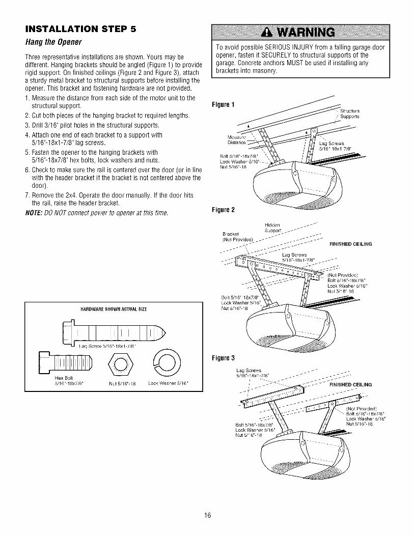
INSTALLATION STEP 5
Hangthe Opener
Three representative installations are shown. Yours may bedifferent. Hanging brackets should be angled (Figure 1) to providerigid support. Onfinished ceilings (Figure 2 and Figure 3), attacha sturdy metal bracket to structural supports before installing theopener. This bracket and fastening hardware are not provided.1. Measurethe distance from each side of the motor unit to the
structural support.
2. Cut both piecesof the hanging bracket to required lengths.
3. Drill 3/16" pilot holes in the structural supports.
4. Attach one end of each bracket to a support with5/16"-18xl -7/8" lag screws.
5. Fastenthe opener to the hanging brackets with5/16"-18x7/8" hex bolts, lock washers and nuts.
6. Checkto make sure the rail is centered over the door (or in linewith the headerbracket if the bracket is not centeredabove thedoor).
7. Removethe 2x4. Operatethe door manually. If the door hitsthe rail, raise the header bracket.
NOTE:DO NOTconnect power to openerat this time.
HARDWARESHOWN ACTUALSIZE
Hex Bolt5/16"-18x7/8" Nut 5/16"-18 Lock Washer 5/16"
To avoid possible SERIOUSINJURYfrom afalling garage dooropener, fasten it SECURELYto structural supports of thegarage. Concrete anchors MUST be used if installing anybrackets into masonry.
Figure 1
Supports
Measure ',Distance
Bolt 5/16"-18x7/8"LockNut 5/16"-18
Lag Screws5/16"-18xl -7/8"
Figure 2
Bolt 5/16"-18x7/8"Lock Washer 5/16"Nut 5/16"- 18
FINISHED CEILING
(Not Provided)Bolt 5/16"-18x7/8"
Lock Washer 5/16"Nut 5/16"-18
Figure 3
Bolt 5/16"-18x7/8"Lock Washer 5/16"Nut 5/16"- 18
(Not Provided)Bolt 5/16"-18x7/8"
Lock Washer 5/16"Nut 5/16"-18
16

INSTALLATION STEP 6
Install theDoorControl
Locate door control within sight of door, at a minimum height of5 feet (1.5 m) where small children cannot reach, awayfrommoving parts of door and door hardware.
1. Strip 1/4" (6 mm) of insulation from one end of bell wire andconnect to the two terminal screws on back of door control bycolor: white to 2 and white/red to 1.
2. Fastenthe Door Control Button securely with 6ABx1-1/2"screws. If installing into drywall, drill 5/32" holes and use theanchors provided.
3. Run bell wire up wall and across ceiling to motor unit. Useinsulated staples to secure wire in severalplaces. Do not piercewire with a staple, creating a short or open circuit.
4. Connect the bell wire to the quick-connect terminals on themotor unit panel: white to white; white/red to red.
5. Position the antenna wire as shown.
6. Usetacks or staples to permanently attach entrapment warninglabel to wall near door control, and manual release/safetyreversetest label in a prominent location on inside of garagedoor.
NOTE:DO NOTconnect power and operate opener at this time.The trolley will travel to the furl open position but will not returnto the close position until the sensor beam is connected andproperly aligned.
To prevent possible SERIOUSINJURYor DEATHfromelectrocution:
• Besure power is not connected BEFOREinstalling doorcontrol.
• Connect ONLYto 24 VOLTlow voltage wires.
To prevent possible SERIOUSINJURYor DEATHfrom a closinggaragedoor:
• Install door control within sight of garagedoor, out of reachof children at a minimum height of 5 feet (1.5 m) and awayfrom ALL moving parts of door.
• NEVERpermit children to operate or play with door controlpush buttons or remote control transmitters.
• Activate door ONLYwhen it can be seen clearly, is properlyadjusted and there are no obstructions to door travel.
• ALWAYS keepgarage door in sight until completely closed.NEVERpermit anyone to cross path of closing garage door.
HARDWARESHOWN ACTUALSIZE
Screw 6ABx1-1/2" Insulated
Lighted Door Control Button Drywall Anchors Staples
Te,e ,w t, VV,re(BACK VIEW)
DOOR CONTROL BUTTON
Quick-Connect
To release or insert wire,
push in tab withscrewdriver tip
Strip wire 7/16" Red/(11 mm)
7/16" (11 mrn)l
Door ControlConnections
White Grey Antenna
17

INSTALLATION STEP 7
Install theLights
• Pressthe releasetabs on both sides of lens. Gentlyrotate lensback and downward until the lens hinge is in the fully openposition. Do not removethe lens.
• Install a 100 watt maximum light bulb in each socket. Lightbulb size should be A19, standard neckonly. The lights willturn ON and remain lit for approximately 4-1/2 minutes whenpower is connected.Then the lights will turn OFF.
• Reversethe procedure to close the lens.
• UseA19, standard neck garagedoor opener bulbs forreplacement.
NOTE:Useonly standard light bulbs. The use of short neck orspeciafity light bulbs may overheat the endpanel or light socket.
To prevent possible OVERHEATINGof the endpanelor lightsocket:
• DONOTuse short neck or specialty light bulbs.• DONOTuse halogen bulbs. UseONLY incandescent.
To prevent damageto the opener:
• DONOTuse bulbs larger than IOOW.• ONLY use A19 size bulbs.
Release Tab
100 Watt (Max) _ )Standard Light Bulb
//
/
100 Watt (Max)Standard
Light Bulb --
LensHinge
INSTALLATION STEP 8
AttachtheEmergencyRe/ease Ropeand Hand/e
- Thread one end of the rope through the hole in the top of thered handleso "NOTICE"reads right side up as shown. Securewith an overhand knot at least 1" (2.5 cm) from the end of theropeto prevent slipping.
• Thread the other end of the rope through the hole in the releasearm of the outer trolley.
• Adjust rope length so the handle is 6 feet (1.83 m) above thefloor. Ensurethat the rope and handle clear the tops of allvehicles to avoid entanglement.Secure with an overhand knot.
NOTE:If it is necessaryto cut the rope, heat seal the cut end witha match or lighter to prevent unraveling.
To prevent possible SERIOUSINJURYor DEATHfrom a fallinggaragedoor:
• If possible, use emergency release handleto disengagetrolley ONLY when garagedoor is CLOSED.Weakor brokensprings or unbalanced door could result in an open doorfalling rapidly and/or unexpectedly.
• NEVERuse emergency releasehandle unless garagedoorway is clear of persons and obstructions.
• NEVERuse handle to pull door open or closed. If rope knotbecomes untied, you could fall.
Trolley
I
Emergency _ _. Overhand
Release Handle _Knot
18

INSTALLATION STEP 9
E/ectrica/ Requirements
To avoid installation difficulties, do notrun the openerat thistime.
To reduce the risk of electric shock, your garagedoor opener hasa grounding type plug with a third grounding pin. This plug willonly fit into a grounding type outlet. If the plug doesn't fit into theoutlet you have, contact a qualified electrician to install the properoutlet.
RIGH_
To prevent possible SERIOUSINJURYor DEATHfromelectrocution or fire:
• Besure power is not connected to the opener, anddisconnect power to circuit BEFOREremoving cover toestablish permanentwiring connection.
• Garagedoor installation and wiring MUST be in compliancewith ALL local electrical and building codes.
• NEVERuse an extension cord, 2-wire adapter or changeplug in ANY way to make it fit outlet. Besure the opener isgrounded.
PERMANENT WIRING
CONNECTION
If permanent wiring is requiredby your local code, refer to thefollowing procedure.
To make a permanent connection through the 7/8" hole in the topof the motor unit:
• Removethe motor unit cover screws and set the cover aside.
• Removethe attached 3-prong cord.
• Connect the black (line) wire to the screw on the brassterminal; the white (neutral) wire to the screw on the silverterminal; and the ground wire to the green ground screw. Theopenermust be grounded.
• Reinstallthe cover.
To avoid installation difficulties, do notrun the openerat thistime.
Ground Tab
GreenGround Screw
Ground Wire
White Wire Wire
19

INSTALLATION STEP 10
Install TheProtectorSystem
Thesafety reversingsensormust be connectedand alignedcorrectlybefore the garage dooropenerwill move in the downdirection.
IMPORTANTINFORMATIONABOUTTHESAFETYREVERSINGSENSOR
When properly connected and aligned, the sensor will detect anobstacle in the path of its electronic beam. The sending eye (withan amber indicator light) transmits an invisible light beam to thereceiving eye (with a green indicator light). If an obstructionbreaks the light beam while the door is closing, the door will stopand reverseto full open position, and the opener lights will flash10 times.
The units must be installed inside the garageso that the sendingand receivingeyes face each other across the door, no more than6" (15 cm) above the floor. Either can be installed on the left orright of the door as long as the sun never shines directly into thereceiving eye lens.
The mounting brackets are designed to clip onto the track ofsectional garagedoors without additional hardware.
Be sure power is not connected to the garagedoor openerBEFOREinstalling the safety reversing sensor.
To prevent SERIOUSINJURY or DEATHfrom a closing garagedoor:
• Correctly connect and align the safety reversingsensor. Thisrequired safety deviceMUST NOTbe disabled.
• Install the safety reversing sensor so beam is NO HIGHERthan 6" (15 cm) above garagefloor.
If it is necessaryto mount the units on the wall, the bracketsmust be securely fastened to a solid surface such as the wallframing. Extension brackets (see Accessories) are availableifneeded. If installing in masonry construction, add a piece of woodat each location to avoid drilling extra holes in masonry ifrepositioning is necessary.
The invisible light beam path must be unobstructed. No part ofthe garagedoor (or door tracks, springs, hinges, rollers or otherhardware) may interrupt the beam while the door is closing.
IH, i 111
Facingthe doorfrom insidethe garage
2O

INSTALLINGTHE BRACKETS
Be sure power to the opener is disconnected. Install and alignthe brackets so the sensors will face each other across the garagedoor, with the beam no higher than 6" (15 cm) above the floor.They may be installed in one of three ways, as follows.
Garage doortrack installation (preferred):
* Slip the curved arms over the rounded edge of each door track,with the curved arms facing the door. Snap into place againstthe side of the track. It should lie flush, with the lip hugging theback edge of the track, as shown in Figure 1.
If your door track will not support the bracket securely,wallinstallation is recommended.
Wall installation (Figure 2 & 3):
* Placethe bracket against the wall with curved arms facing thedoor. Besure there is enough clearancefor the sensor beam tobe unobstructed.
o If additional depth is needed,an extension bracket (seeAccessories) or wood blocks can be used.
o Usebracket mounting holes as a template to locate anddrill (2) 3/16" diameter pilot holes on the wall at each side ofthe door, no higher than 6" (15 cm) abovethe floor.
o Attach brackets to wall with lag screws (not provided).
o If using extension brackets or wood blocks, adjust right andleft assembliesto the same distance out from the mountingsurface. Make sure all door hardware obstructions are cleared.
Floor installation (Figure 4):
• Usewood blocks or extension brackets (see Accessories) toelevatesensor bracketsso the lenseswill be no higher than6" (15 cm) abovethe floor.
• Carefully measure and place right and left assembliesat thesame distance out from the wall. Besure all door hardwareobstructions are cleared.
• Fastento the floor with concrete anchors as shown.
Figure 1DOOR TRACK MOUNT (RIGHT SIDE)
L Door
_ Track
I1' upIndicatorLight
Figure 2 WALL MOUNT (RIGHT SIDE)
Fasten Wood Block to Wall with
Lag Screws (Not Provided)Indicator
_ Light S enskort
- screws> (Not Provided)
Lens - -_
Figure 3
(Provided withExtension ._ _Bracket)
WALL MOUNT (RIGHT SIDE)
Extension
Bracket(See Accessories)
I_r_ (Provided with
-- _r_ I Extension Bracket)
_ (._/'_/"_-_ Sensor
_C_i'_ " Bracket
I IndicatorLens Light
Figure 4 FLOOR MOUNT (RIGHT SIDE)
HARDWARESHOWN ACTUALSIZE
Carriage Bolt Wing Nut Staples1/4"-20xl/2" 1/4"-20
f
_l-- Attach with
Concrete Anchors; (Not Provided)
Light
Sensor--S-Bracket
21

MOUNTINGANDWIRING THESAFETYREVERSINGSENSORS
• Slide a 1/4"-20xl/2" carriage bolt head into the slot on eachsensor. Usewing nuts to fasten sensors to brackets, withlenses pointing toward each other across the door. Besure thelens is not obstructed by a bracket extension (Figure 5).
• Finger tighten the wing nuts.
• Run the wires from both sensors to the opener. Use insulatedstaples to secure wire to wall and ceiling.
° Strip 7/16" (11 mm) of insulation from each set of wires.Separatewhite and white/black wires sufficiently to connect tothe opener quick-connect terminals. Twist like colored wirestogether. Insert wires into quick-connect holes: white to whiteand white/black to grey (Figure 6).
ALIGNINGTHESAFETYREVERSINGSENSORS
• Plug in the opener. The indicator lights in both the sending andreceiving eyeswill glow steadily if wiring connections andalignment are correct.
The sending eyeamber indicator light will glow regardlessofalignment or obstruction. If the green indicator light in thereceiving eye is off, dim, or flickering (and the invisible light beampath is not obstructed), alignment is required.
° Loosenthe sending eyewing nut and readjust, aiming directlyat the receiving eye.Lock in place.
° Loosenthe receiving eye wing nut and adjust sensor until itreceivesthe sender's beam. When the green indicator lightglows steadily, tighten the wing nut.
Figure 5
Wing Nut1/4"-20
Lens
TROUBLESHOOTINGTHESAFETYREVERSINGSENSORS
1. If the sending eyeindicator light does not glow steadily afterinstallation, check for:
° Electric power to the opener.° A short in the white or white/black wires. Thesecan occur at
staples, or at opener connections.
° Incorrect wiring betweensensors and opener.° A broken wire.
2. If the sending eyeindicator light glows steadily but thereceiving eye indicator light doesn't:
° Check alignment.
° Checkfor an open wire to the receiving eye.
3. If the receiving eye indicator light is dim, realign either sensor.
NOTE:When the invisible beam path is obstructed or misalignedwhile the door is closing, the door will reverse. If the door isalready open, it will not close. The opener lights will blink 10times. Seepage 20.
Figure 6
Bell Wire
Connect Wire toQuick-Connect Terminals
Bell Wire\
1. Strip wire 7/16"(11 mm)
7/16" (11 mm}l
2. Twist like coloredwires together
3. To release or insert
wire, push in tab withscrewdriver tip
Safety Reversing Sensor
Invisible Light BeamProtection Area
Safety Reversing Sensor
22
Red White Grey
Quick-Connect Terminals

INSTALLATION STEP 11
Fastenthe DoorBracket
Follow instructions which apply to your door type as illustratedbelow or on the following page.
A horizontal reinforcementbraceshouldbe longenoughto besecuredto two vertical supports.A vertical reinforcementbraceshouldcoverthe heightof the toppanel.
The illustrationshows one piece of angle ironas the horizontalbrace. For the vertical brace, two piecesof angle iron are used tocreate a U-shapedsupport (Figure 1). The best solution is tocheck with your garage door manufacturer for an openerinstallation door reinforcement kit.
NOTE:Many vertical brace installations provide for directattachment of the clevis pin and door arm. In this caseyou willnot need the door bracket, proceed to Installation Step 12.
SECTIONALDOORS
• Center the door bracket on the previously marked verticalcenterline used for the headerbracket installation. Note correctUP placement,as stamped inside the bracket (Figure 2).
• Position the bracket on the face of the door within thefollowing limits:
A) The top edgeof the bracket 2"-4" (5-10 cm) below the topedge of the door.
B) The top edgeof the bracket directly below any structuralsupport across the top of the door.
Fiberglass,aluminum or lightweight steel garagedoors WILLREQUIREreinforcement BEFOREinstallation of door bracket.Contactyour door manufacturer for reinforcement kit.
HARDWARESHOWN ACTUALSIZE
Nut 5/16"-18 Lock Washer 5/16"
Carriage Bolt5/16"-18x2-1/2"
• Mark and drill 5/16" left and right fastening holes. Secure thebracket as shown in Figure 1 if there is vertical reinforcement.
If your installation doesn't require vertical reinforcement but doesneedtop and bottom fastening holes for the door bracket, fastenas shown in Figure 2.
Header BracketHorizontal and vertical reinforcement
is needed for lightweight garage doors(fiberglass, aluminum, steel, doors withglass panel, etc.). (Not Provided)
VerticalReinforcement
Vertical
Vertical
of GarageDoor
Edgeof Door or
einforcement
Board
Carriage Bolt5/16"-18x2-1/2"
DoorBracket
Lock Washer5/16"
Nut5/16"-18
"@0.
@-QDoor Bracket
Figure2
Door
UP
Figure1
23

ONE-PIECEDOORS
Please readand comply with the warnings and reinforcementinstructions on the previous page. They apply to one-piece doorsalso.
• Center the door bracket on the top of the door, in line with theheader bracket as shown. Mark either the left and right, or thetop and bottom holes.
• Drill 5/16" pilot holes and fasten the bracket with hardwaresupplied.
If the door has no exposedframing, drill 3/16" pilot holes andfasten the bracket with 5/16"x1-1/2" lag screws (not provided) tothe top of the door.
NOTE:Thedoor bracket may be installed on the top edgeof thedoor if required for your installation. (Refer to the dotted lineoptional placement drawing). Drill 3/16" pilot holes and substitute5/16"x1-1/2" lag screws (not provided) to fasten the bracket to thedoor.
HARDWARESHOWN ACTUALSIZE
Nut 5/16"-18 Lock Washer 5/16"
Carriage Bolt5/16"- 18x2-1/2"
Header Wall
2x4-- Finished Ceiling --
HeaderBracket
OptionalPlacementof DoorBracket
DoorBracket
VerticalCenterlineof GarageDoor
Horizontal and verticalreinforcement is needed for
.=doors
(fiberglass, aluminum, steel,door with glass panel, etc.).(Not Provided)
5/16"-18_
Door
For a door with no exposed framing,or for the optional installation, use5/16"xl-1/2" lag screws (Not Provided)to fasten door bracket.
®,_ LockWasher
' 5/16"iii
Top of Door
Top Edgeof Door
OptionalPlacement
Carriage Bolt
5/16"- 18x2-1/2"
24

INSTALLATION STEP 12
ConnectDoorArm to Trolley
Follow instructions which apply to your door type as illustratedbelow and on the following page.
SECTIONALDOORSONLY
Make sure garagedoor is fully closed. Pull the emergency releasehandle to disconnect the outer trolley from the inner trolley. Slidethe outer trolley back (awayfrom the pulley) about 8" (20 cm) asshown in Figures 1, 2 and 3.
Figure 1:
,, Fastenstraight door arm section to outer trolley with the5/16"x1" clevis pin. Secure the connection with a ring fastener.
• Fastencurved section to the door bracket in the same way,using the 5/16"x1-1/4" clevis pin.
Figure 2:
,, Bring arm sections together. Find two pairs of holes that line upand join sections. Select holes as far apart as possible toincrease door arm rigidity.
Figure 3, Hole alignment alternative:
,, If holes in curved arm are above holes in straight arm,disconnect straight arm. Cut about 6" (15 cm) from the solidend. Reconnect to trolley with cut end down as shown.
• Bring arm sections together.
• Find two pairs of holes that line up and join with bolts, lockwashers and nuts.
Pull the emergency releasehandle toward the opener at a 45°angle so that the trolley releasearm is horizontal. ProceedtoAdjustment Step 1, page27. Trolley will re-engageautomaticallywhen opener is operated.
Figure 1
Figure 2
Pulleyi i
/!(i-8" (20crn) rnin.___..),,
I O ....7_ :-Trolley
OuterStop Bolt / Inner I I ', _1
Rin _ Troileylld Trolleyg 1ol _ ClevisPin
r-astener I 115/16:x1:iOl,_k._ Emergency
,,,, r-'l'......._ Releaseu Door I°1_ Handle
Bracket lYlStraightDoor Arm
Clevis Pin5/16"xl -1/4"
Curved Door Arm
Pulley
Door Bracket
Bolts
E
HARDWARESHOWN ACTUALSIZE
Nut 5/16"-18
Clevis Pin
5/16"xl" (Trolley)
Lock Washer 5/16" ' er
Clevis Pin Hex Bolt
5/16"x1-1/4" (Door Bracket) 5/16"-18x7/8"
Figure 3
Pulley
/ :,(__8" (20 crn) rnin. _..):,
Tro,',ey --Stop Bolt / /
Lv_Ckhers,_/n°/
Nuts 5/16" /o7
25

ALLONE-PIECEDOORS
1 Assemblethe doorarm, Figure 4:
• Fastenthe straight and curved door arm sections together tothe longest possible length (with a 2 or 3 hole overlap)
• With the door closed, connect the straight door arm sectionto the door bracket with the 5/16 xl 1/4 clevis pin
• Secure with a ring fastener
2. Adjustmentprocedures,Figure 5:
• On one-piece doors, before connecting the door arm to thetrolley, the travel limits must be adjusted. Limit adjustmentscrews are located on the left side panel as shown on page27. Follow adjustment procedures below.
• Open dooradjustment:decreaseUP travel limit
- Turn the UP limit adjustment screw counter-clockwise 4turns.
- Pressthe Door Control push button. The trolley will travel tothe fully open position.
- Manually raise the door to the open position (parallel to thefloor), and lift the door arm to the trolley. The arm shouldtouch the trolley just in back of the door arm connectorhole. Refer to the fully open trolley/door arm positions in theillustration. If the arm does not extend far enough, adjustthe limit further. Onefull turn equals 2" (5 cm) of trolleytravel.
° Closeddooradjustment:decreaseDOWNtravel limit
- Turn the DOWNlimit adjustment screw clockwise4 complete turns.
Door
Bracket _ _ _ _ Ring_"'_%_- _:._'_ Fastener
_- _\_._--_.._ Nuts|_>_-_ _>'_,_--_,,,_ Lock 5/16"-18_-__ _.,_'_._ Washers I _'_
J _ _._Q_._ 5/16" I I_/I
ClevisPin Straight '-f I I /I
Bolts (_:_ /5_1'_, 18X7/8,, _------_ I_ "__'Cu rved
Figure 4 Door Arm
- Pressthe Door Control push button. The trolley will travel tothe fully closed position.
- Manually close the door and lift the door arm to the trolley.The arm should touch the trolley just aheadof the door armconnector hole. Refer to the fully closedtrolley/door armpositions in the illustration. If the arm is behindtheconnector hole, adjust the limit further. Onefull turn equals2" (5 cm) of trolley travel.
3. Connectthe doorarm to the trolley:
° Closethe door andjoin the curved arm to the connector holein the trolley with the remaining clevis pin. It may benecessaryto lift the door slightly to makethe connection.
• Secure with a ring fastener.
° Run the opener through a complete travel cycle. If the doorhas a slight "backward" slant in full open position as shownin the illustration, decreasethe UP limit until the door isparallel to the floor.
NOTE: When setting the up limit on the foflowing page, the doorshould not have a "backward" slant when fully open as illustratedbelow. A slight backward slant will cause unnecessarybuckingand/or jerking operation as the door is being openedor closedfrom the fully open position.
Figure 5Inner Trolley
lley
Emergency Release Handle
Inner Trolley
Outer Trolley
Open Door (Incorrect)
26

ADJUSTMENT STEP 1
AdjusttheUP and DOWNTravelLimits
Limit adjustment settings regulatethe points at which the doorwill stop when moving up or down.
To operate the opener, press the Door Control push bar. Run theopener through a complete travel cycle.
• Doesthe door open and close completely?
• Doesthe door stay closed and not reverseunintentionally whenfully closed?
If your door passes both of these tests, no limit adjustments arenecessaryunless the reversing test fails (see Adjustment Step 3,page 29).
Adjustment procedures are outlined below. Readthe procedurescarefully before proceeding to Adjustment Step 2. Useascrewdriver to make limit adjustments. Runthe openerthroughacompletetravel cycleafter each adjustment.
NOTE:Repeatedoperation of the opener during adjustmentprocedures may cause the motor to overheatand shut off. Simplywait 15 minutes and try again. If anything interferes with thedoor's upward travel, it will stop. If anything interferes with thedoor's downward travel (including binding or unbalanced doors),it will reverse.
HOWAND WHENTO ADJUSTTHE LIMITS
• If the doordoesnot open completelybut opensat least fivefeet (1.5 m):
Increase up travel. Turn the UP limit adjustment screwclockwise. Oneturn equals 2" (5 cm) of travel.
NOTE:Toprevent the trolley from hitting the coverprotectionbolt, keep a minimum distance of 2-4"(5 cm - 10 cm) betweenthe trolley and the bolt.
• If doordoesnot openat least 5 feet (1.5 m):
Adjust the UP (open) force as explained in Adjustment Step 2.
• If the doordoesnot closecompletely:
Increase down travel. Turn the down limit adjustment screwcounterclockwise. Oneturn equals 2" (5 cm) of travel.
If door still won't close completely and the trolley bumps intothe pulley bracket (page4), try lengthening the door arm(page 25) and decreasingthe down limit.
• If the openerreversesin fully dosed position:
Decreasedown travel. Turn the down limit adjustment screwclockwise. Oneturn equals 2" (5 cm) of travel.
Without a properly installed safety reversalsystem, persons(particularly small children) could be SERIOUSLYINJUREDorKILLEDby a closing garagedoor.• Incorrect adjustment of garagedoor travel limits will
interfere with proper operation of safety reversalsystem.• If one control (force or travel limits) is adjusted, the other
control may also need adjustment.• After ANY adjustments are made, the safety reversal system
MUST be tested. Door MUST reverse on contact with1-1/2" (3.8 cm) high object (or 2x4 laid flat) on floor.
To prevent damageto vehicles, be sure fully open doorprovides adequateclearance.
Cover Protection BoltI
___2_4., l.--.,,j o o0 0 0__
Left Panel Limit AdjustmentScrews
leADJUSTMENT LABEL
• If the doorreverseswhen closingand there is no visibleinterferenceto travel cycle:
If the opener lightsareflashing, the Safety ReversingSensorsare either not installed, misaligned, or obstructed. SeeTroubleshooting, page22.
Test the door for binding: Pull the emergency releasehandle.Manually open and close the door. If the door is binding orunbalanced,call for a trained door systems technician. If thedoor is balanced and not binding, adjust the DOWN(close)force. SeeAdjustment Step 2.
27

ADJUSTMENT STEP 2
AdjusttheForce
Forceadjustment controls are located on the right panel of themotor unit. Forceadjustment settings regulate the amount ofpower requiredto open and close the door.
If the forces are set too light, door travel may be interrupted bynuisance reversals in the down direction and stops in the updirection. Weatherconditions can affect the door movement, sooccasional adjustment may be needed.
The maximumforceadjustmentrange is about3/4 of acompleteturn. Do not force controls beyond that point. Turnforce adjustment controls with a screwdriver.
NOTE:If anything interferes with the door's upward travel, it willstop. If anything interferes with the door's downward travel(including binding or unbalanced doors), it will reverse.
HOWAND WHENTO ADJUSTTHE FORCES
1. Testthe DOWN(c/ose) force
• Grasp the door bottom when the door is about halfwaythrough DOWN(close) travel. The door should reverse.Reversal halfway through down travel does not guaranteereversal on a 1-1/2" (3.8 cm) obstruction. SeeAdjustmentStep 3, page 29. If the dooris hard to holdor doesn'treverse, decreasethe DOWN (close) force by turningthe control counterclockwise. Make small adjustments untilthe door reverses normally. After each adjustment, run theopener through a complete cycle.
• If the doorreversesduringthe down (close)cycle and theopenerlightsaren't flashing, Increase DOWN(close) forceby turning the control clockwise. Make small adjustmentsuntil the door completes a close cycle. After eachadjustment, run the opener through a complete travel cycle.Do not increase the force beyond the minimum amountrequired to close the door.
2. Testthe UP (open) force
• Grasp the door bottom when the door is about halfwaythrough UP (open) travel. The door should stop. If the dooris hard to hold or doesn'tstop, DECREASEUP (open) forceby turning the control counterclockwise. Make smalladjustments until the door stops easily and opens fully.After each adjustment, run the opener through a completetravel cycle.
• If the doordoesn't openat least 5 feet (1.5 m),INCREASEUP (open) force by turning the control clockwise.Make small adjustments until door opens completely.Readjust the UP limit if necessary.After each adjustment,run the opener through a complete travel cycle.
Without a properly installed safety reversalsystem, persons(particularly small children) could be SERIOUSLYINJUREDorKILLEDby a closing garagedoor.
• Too much force on garage door will interfere with properoperation of safety reversalsystem.
• NEVERincreaseforce beyond minimum amount required toclose garage door.
• NEVERuse force adjustments to compensatefor a bindingor sticking garage door.
• If one control (force or travel limits) is adjusted, the othercontrol may also need adjustment.
• After ANY adjustments are made, the safety reversal systemMUST be tested. Door MUST reverse on contact with1-1/2" (3.8 cm) high object (or 2x4 laid flat) on floor.
Right Panel
0 0
Force AdjustmentControls
®Antenna
ADJUSTMENTLABEL
Open Force Close Force
28
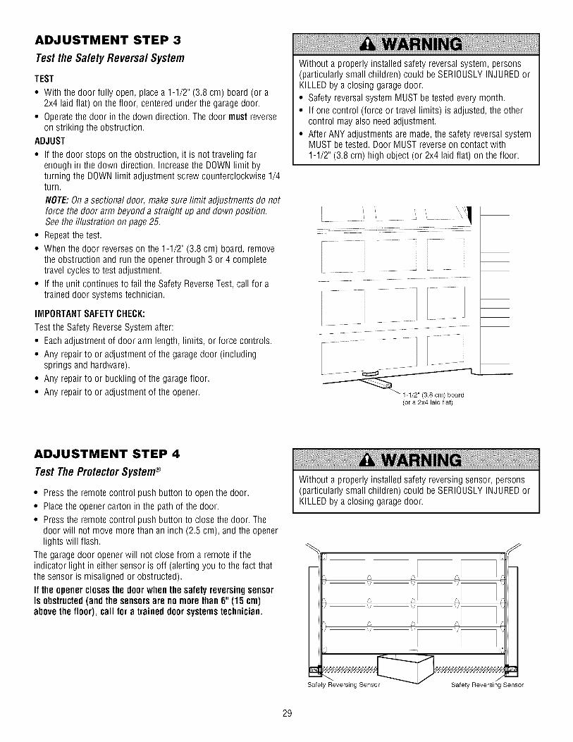
ADJUSTMENT STEP 3
Testthe SafetyReversalSystem
TEST
• With the door fully open, place a 1-1/2" (3.8 cm) board (or a2x4 laid flat) on the floor, centered under the garagedoor.
• Operatethe door in the down direction. The door must reverseon striking the obstruction.
ADJUST
• If the door stops on the obstruction, it is not traveling farenough in the down direction. Increasethe DOWNlimit byturning the DOWNlimit adjustment screw counterclockwise 1/4turn.
NOTE:On a sectional door, make sure limit adjustments do notforce the door arm beyond a straight up and down position.See the illustration on page 25.
° Repeatthe test.
° When the door reverses on the 1-1/2" (3.8 cm) board, removethe obstruction and run the opener through 3 or 4 completetravel cyclesto test adjustment.
° If the unit continues to fail the Safety ReverseTest, call for atrained door systems technician.
IMPORTANTSAFETYCHECK:
Test the Safety ReverseSystem after:
• Each adjustment of door arm length, limits, or force controls.
• Any repair to or adjustment of the garagedoor (includingsprings and hardware).
• Any repair to or buckling of the garagefloor.
• Any repair to or adjustment of the opener.
Without a properly installed safety reversalsystem, persons(particularly small children) could be SERIOUSLYINJUREDorKILLEDby a closing garagedoor.• Safety reversalsystem MUST betested every month.
• If one control (force or travel limits) is adjusted, the othercontrol may also need adjustment.
° After ANY adjustments are made, the safety reversal systemMUST be tested. Door MUST reverse on contact with1-1/2" (3.8 cm) high object (or 2x4 laid flat) on the floor.
(or a 2x4 laid flat)
ADJUSTMENT STEP 4
TestTheProtectorSysterr
° Pressthe remote control push button to open the door.
° Placethe opener carton in the path of the door.
° Pressthe remote control push button to close the door. Thedoor will not move more than an inch (2.5 cm), and the openerlights will flash.
The garage door openerwill not close from a remote if theindicator light in either sensor is off (alerting you to the fact thatthe sensor is misaligned or obstructed).
If the openerclosesthe doorwhenthe safety reversingsensoris obstructed(and the sensorsare nomore than 6" (15 cm)abovethe floor), call for a trained doorsystemstechnician.
Without a properly installed safety reversing sensor, persons(particularly small children) could be SERIOUSLYINJUREDorKILLEDby a closing garagedoor.
Safety Reversing Sensor Safety Reversing Sensor
29

OPERATION
IMPORTANT SAFETY INSTRUCTIONS
To reduce the risk of SEVERE INJURY or DEATH:1. READANDFOLLOWALL WARNINGSAND
INSTRUCTIONS.
2. ALWAYS keep remote controls out of reach of children.NEVERpermit children to operate or play with garagedoorcontrol push buttons or remote controls.
3. ONLYactivategarage door when it can beseen clearly, it isproperly adjusted and there are no obstructions to doortravel.
4. ALWAYS keep garagedoor in sight until completely closed.NOONESHOULDCROSSTHE PATHOFTHE MOVINGDOOR.
5. NOONESHOULDGOUNDERA STOPPED,PARTIALLYOPENEDDOOR.
6. If possible, use emergency releasehandleto disengagetrolley ONLYwhen garagedoor is CLOSED.Weak orbroken springs or unbalanceddoor could result in an opendoor falling rapidly and/or unexpectedly.
7. NEVERuse emergency releasehandle unless garagedoorway is clear of persons and obstructions.
8. NEVERuse handleto pull garagedoor open or closed. Ifrope knot becomes untied, you could fall.
9. If one control (force or travel limits) is adjusted, the othercontrol may also needadjustment.
10. After ANY adjustments are made, the safety reversalsystem MUST betested.
11. Safety reversalsystem MUST betested every month.Garagedoor MUST reverseon contact with 1-1/2" high(3.8 cm) object (or a 2x4 laid flat) on the floor.
12. ALWAYS KEEPGARAGEDOORPROPERLYBALANCED(see page3). An improperly balanceddoor may not reversewhen required and could result in SEVEREINJURY orDEATH.
13. ALL repairs to cables, spring assembliesand otherhardware, ALL of which are under EXTREMEtension,MUST be made by a trained door systems technician.
14. ALWAYSdisconnect electric power to garagedoor openerBEFOREmaking ANY repairs or removing covers.
15.SAVETHESEINSTRUCTIONS.
Using Your Garage Door Opener
Your Security÷® opener and hand-held remote control have beenfactory-set to a matching code which changeswith each use,randomly accessing over 100 billion new codes. Your opener willoperate with up to eight Security+® remote controls and oneSecurity÷® KeylessEntry System. If you purchase a new remote,or if you wish to deactivateany remote, follow the instructions inthe Programming section.
Activateyour openerwith any of the following:
. Thehand-held Remote Controh Hold the large push buttondown until the door starts to move.
. The wall-mounted Door Controh Hold the push button or bardown until the door starts to move.
. The KeylessEntry (SeeAccessories): If provided with yourgaragedoor opener, it must be programmed before use. SeeProgramming.
Whenthe openeris activated(with the safety reversingsensorcorrectlyinstalled and aligned)
1. If open, the door will close. If closed, it will open.
2. If closing, the door will reverse.
3. If opening, the door will stop.
4. If the door has been stopped in a partially open position, it willclose.
5. If obstructed while closing, the door will reverse. If theobstruction interrupts the sensor beam, the opener lights willblink for five seconds.
6. If obstructed while opening, the door will stop.
7. If fully open, the door will not close when the beam is broken.The sensor has no effect in the opening cycle.
If the sensor is not installed, or is misaligned, the door won'tclose from a hand-held remote. However,you can close the doorwith the Door Control or KeylessEntry, if you activatethem untildown travel is complete. If you releasethem too soon, the doorwill reverse.
Theopenerlightswill turn on under the following conditions:when the opener is initially plugged in; when power is restoredafter interruption; when the opener is activated.
Theywill turn off automatically after 4-1/2 minutes or provideconstant light when the Light feature on the Motion DetectingControl Console is activated. Bulb size is A19. Bulb power is 100watts maximum.
Security.I.° light feature: Lights will also turn on when someonewalks through the open garagedoor. With a Motion DetectingControl Console,this feature may be turned off as follows: Withthe opener lightsoff, press and hold the lightbutton for 10seconds, until the lightgoes on, then off again. To restore thisfeature, start with the opener lightson, then press and hold thelightbutton for 10 seconds until the lightgoes off, then on again.
3O

Using the Wall-Mounted Door Control
Press the push button to open or close the door.Press againto reversethe door during the closingcycle or to stop the door while it's opening.
To Openthe DoorManually
To prevent possible SERIOUSINJURYor DEATHfrom a fallinggaragedoor:• If possible, use emergency release handleto disengage
trolley ONLY when garagedoor is CLOSED.Weakor brokensprings or unbalanced door could result in an open doorfalling rapidly and/or unexpectedly.
• NEVERuse emergency releasehandle unless garagedoorway is clear of persons and obstructions.
• NEVERuse handle to pull door open or closed. If rope knotbecomes untied, you could fall.
DISCONNECTTHETROLLEY:
The door should be fully closed ifpossible. Pull down on theemergency releasehandle (so thatthe trolley releasearm snaps into avertical position) and lift the doormanually. The lockout featureprevents the trolley fromreconnecting automatically, and thedoor can be raised and loweredmanually as often as necessary.
TO RE-CONNECTTHETROLLEY:
Pull the emergency release handletoward the opener at an angle sothat the trolley releasearm ishorizontal. The trolley willreconnect on the next UP or DOWNoperation, either manually or byusing the door control or remote.
Trolley
Trolley -- ._._Release Arm
(In ManualDisconnect
Position)
Lockoutposition(Manual disconnect)
Trolley
TrolleyRelease
_. _ Arm
Emergency "%Release Handle _ -\\ ._
(Down and Back) _£.,'
TOreconnect
31
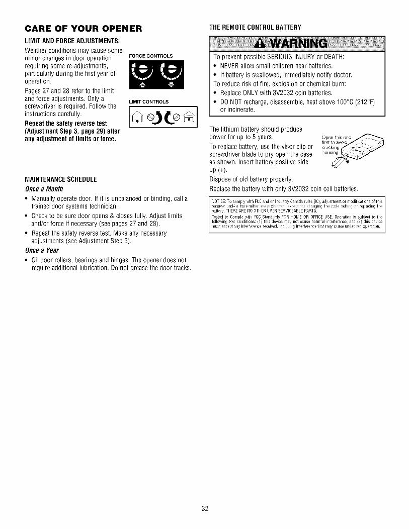
CARE OF YOUR OPENER
LIMIT AND FORCEADJUSTMENTS:
Weatherconditions may causesomeminor changes in door operationrequiring some re-adjustments,particularly during the first year ofoperation.
Pages 27 and 28 refer to the limitand force adjustments. Only ascrewdriver is required. Follow theinstructions carefully.
Repeatthe safetyreversetest(AdjustmentStep 3, page 29) afterany adjustmentof limits or force.
FORCECONTROLS
LIMIT CONTROLS
MAINTENANCESCHEDULE
Oncea Month
• Manually operate door. If it is unbalancedor binding, call atrained door systems technician.
• Checkto be sure door opens & closes fully. Adjust limitsand/or force if necessary(see pages27 and 28).
• Repeatthe safety reversetest. Make any necessaryadjustments (see Adjustment Step 3).
Oncea Year
• Oil door rollers, bearings and hinges. The opener does notrequire additional lubrication. Do not greasethe door tracks.
THEREMOTECONTROLBATTERY
To prevent possible SERIOUSINJURYor DEATH:• NEVERallow small children near batteries.
• If battery is swallowed, immediately notify doctor.To reduce risk of fire, explosion or chemical burn:
• ReplaceONLYwith 3V2032 coin batteries.• DONOT recharge,disassemble, heat above 100°C (212°F)
or incinerate.
The lithium battery should producepower for up to 5 years.
To replace battery, use the visor clip orscrewdriver bladeto pry open the caseas shown. Insert battery positive sideup (+).
Dispose of old battery properly.
Open this endfirst to avoid/_. < _'_,_Jcracking f (_ kS--<_,_?-_
hous_
Replacethe battery with only 3V2032 coin cell batteries.
NOTICE:To comply with FCCand or Industry Canadarules (IC),adjustment or modifications of thisreceiverand/or transmitter are prohibited, except for changing the code setting or replacingthebattery.THEREARENOOTHERUSERSERVICEABLEPARTS.
Tested to Comply with FCCStandards FOR HOMEOR OFFICEUSE. Operation is subject to thefollowing two conditions: (1) this device may not cause harmful interference,and (2) this devicemust acceptany interference received,including interferencethat may cause undesiredoperation.
32

HAVING A PROBLEM?
1. My doorwill notclose andthe light bulbsblink on mymotorunit: The safety reversing sensor must be connected andaligned correctly before the garagedoor opener will move inthe down direction.
* Verify the safety sensors are properly installed, aligned andfree of any obstructions. Refer to Installation Step 10: InstaflTheProtector System° .
• Check diagnostic LED for flashes on the motor unit thenrefer to the Diagnostic Chart on the following page.
2. My remoteswill notactivate the door:
• Reprogram remotes following the programminginstructions. Refer to Programming.
• If remote will still not activateyour door, check diagnosticLEDfor flashes on motor unit then refer to Diagnostic Charton the following page.
3. My doorreversesfor noapparentreason: Repeatsafetyreversetest after adjustments to force or travel limits. The needfor occasional adjustment for the force and limit settings isnormal. Weatherconditions in particular can affect door travel.
• Manually check door for balance or any binding problems.
• Refer to Adjustment Step 2, Adjust the force.
4. My doorreversesfor noapparentreason after fully closingand touchingthe floor: Repeatsafety reversetest afteradjustments to force or travel limits. The needfor occasionaladjustment for the force and limit settings is normal. Weatherconditions in particular can affect door travel.
• Refer to Adjustment Step 1, Adjust the UPand DOWN TravelLimits. Decreasedown travel by turning down limitadjustment screw clockwise.
5. My lightswill notturn off whendoor is open:
• The garage door opener is equipped with a security lightfeature. This feature activates the light on when the safetysensor beam has been obstructed. SeeAccessories page.
Safet Reversing Sensor
Bell Wire
-4
@ @
LEDorIIlII I
Sending Eye Safety ReversingSensor (Amber Indicator Light)
\
Receiving Eye Safety ReversingSensor (Green Indicator Light)
6. My motor unit humsbriefly:
• First verify that the trolley is against the stop bolt.
• Releasethe door from the opener by pulling the EmergencyReleaseRope.
• Manually bring the door to a closed position.
• Loosen the belt by adjusting the outernut4 to 5 turns. Thisrelievesthe tension.
• Run the motor unit from the remote control or door control.The trolley should travel towards the door and stop. If thetrolley re-engageswith the door, pull the EmergencyReleaseRope to disengage.
• Decreasethe UP travel by turning the UP Travel adjustmentscrew 2 full turns awayfrom the arrow.
_1_ 1-1/4"
(3.18 cm)
• Re-Tightenthe outer nut until the trolley spring isapproximately 1-1/4" (3.18 cm) in length.
• If the trolley does not move awayfrom the bolt, repeat thesteps above.
33

J
Safety Reversing Sensor
Diagnostic Chart
Bell Wire
\
Safetyreversingsensorswire open (brokenordisconnected).
OR
Safetyreversingsensorswireshortedor black/whitewirereversed.
Doorcontrolorwire shorted.
Safety reversingsensorsslightly misaligned(dim or flashing LED).
Motoroverheatedor possibleRPM sensorfailure. Unplugto reset.
Motor CircuitFailure.Replace ReceiverLogicBoard.
"0
"0
"0
"'0
"'0
Symptom:One or both of the Indicatorfights on the safety reversingsensorsdo notglowsteady.
• Inspect sensor wires for a short (staple in wire), correct wiring polarity (black/white wiresreversed), broken or disconnected wires, replace/attachas needed.
• Disconnect all wires from back of motor unit.
• Remove sensors from bracketsand shorten sensor wires to 1-2 ft (30-60 cm) from back ofeach sensor.
• Reattachsending eye to motor unit using shortened wires. If sending eye indicator lightglows steadily, attach the receiving eye.
• Align sensors, if the indicator lights glow replacethe wires for the sensors. If the sensorindicator lights do not light, replacethe safety reversing sensors.
Symptom:LED is not lit on doorcontro/.
• Inspect door control/wires for a short (staple in wire), replaceas needed.
• Disconnect wires at door control, touch wires together. If motor unit activates, replace doorcontrol.
° If motor unit does not activate, disconnect door control wires from motor unit. Momentarilyshort across red and white terminals with jumper wire. If motor unit activates, replacedoorcontrol wires.
Symptom:Sendingindicatorfight glowssteadily, receiving indicatorlight is dim or flashing.
° Realign receiving eye sensor, clean lens and secure brackets.
• Verify door track is firmly securedto wall and does not move.
Symptom:Motor has overheated;the motorunit doesnotoperate or trolley is stuckonstopbolt = Motor unit humsbrief/y; RPM Sensor= Shorttravel 6-8" (15-20 cm).
• Unplug unit to reset. Try to operate motor unit, check diagnostic code.
° If it is still flashing 5 times and motor unit moves 6-8" (15-20 cm), replace RPMsensor.
• If motor unit doesn't operate, motor unit is overheated.Wait 30 minutes and retry. If motorunit still will not operate replace logic board.
Symptom:Motor unit doesn't operate.
• Replacelogic board becausemotor rarely fails.
34

PROGRAMMING
NOTICE:If this Security+_ garage door opener is operated with a non-rolling code transmitter, the technical measure in the receiverofthe garage door opener, which provides security against code-theft devices, will be circumvented. Theowner of the copyright in thegarage door opener does not authorize the purchaser or supplier of the non-rolling code transmitter to circumvent that technicalmeasure.
Your garagedoor opener has already been programmed at the factory to operate with your hand-held remote control. The door willopen and close when you press the large push button.
Below are instructions for programming your opener to operate with additional Security÷® 315 MHz remote controls.
ToAdd or Reprograma Hand-heldRemote Control
USINGTHE "LEARN" BUTTON
To Erase All Codes From Motor Unit Memory
To deactivateany unwanted remote, first erase all codes:
Pressand hold the "learn" button on motor LL_unit until the learn indicator light goes out L /(approximately 6 seconds). All previous codes "-'h-2Le)_ _ /are now erased. Reprogram each remote or I ill e ,essent wishtouse
"! w/
1. Pressand releasethe "learn" button on themotor unit. The learn indicator light willglow steadily for 30 seconds.
2. Within 30 seconds, press and hold thebutton on the hand-held remote* that youwish to operateyour garage door.
4. Releasethe button when the motor unitlights blink. It has learnedthe code. If lightbulbs are not installed, two clicks will beheard.
\1 /
*3-Function Remotes (315 MHz)
If provided with your garage door opener, the large button isfactory programmed to operate it. Additional buttons on anySecurity÷® 3-Function remote ,,,-"P':_ _or compact remote can beprogrammed to operate otherSecurity÷® garage dooropeners.
35

To Add, Reprogram or Change a Key/ess Entry PIN
NOTE:Your new KeylessEntry must be programmed to operateyour garage door opener.
USINGTHE "LEARN" BUTTON
1. Pressand releasethe "learn" button onmotor unit. The learn indicator light willglow steadily for 30 seconds.
2. Within 30 seconds, enter a four digitpersonal identification number (PIN) ofyour choice on the keypad. Then pressand hold the ENTERbutton.
3. Releasethe button when the motor unitlights blink. It has learnedthe code. Iflight bulbs are not installed, two clicks willbe heard.
\1 /
One ButtonC/ose:Openercan be closed by pressing only theENTERbutton if the one button close feature has beenactivated.This feature has been activatedat the factory. To activateordeactivatethis feature press and hold buttons 1 and 9 for 10seconds. The keypadwill blink twice when the one button close isactive. The keypadwill blink four times when one button close isdeactivated.
Tochangean existing, knownPIN
If the existing PIN is known, it may be changed by one personwithout using a ladder.
1. Pressthe four buttons for the present PIN, then press and holdthe # button.
The opener light will blink twice. Releasethe # button.
2. Pressthe new 4-digit PINyou have chosen, then press ENTER.
The motor unit lights will blink once when the PIN has beenlearned.
Test by pressing the new PIN, then press ENTER.The doorshould move.
Toset a temporary PIN
You may authorize accessby visitors or service peoplewith atemporary 4-digit PIN. After a programmed number of hours ornumber of accesses,this temporary PINexpires and will nolonger open the door. It can be used to close the door even afterit has expired. To set a temporary PIN:
1. Pressthe four buttons for your personal entry PIN (not the lasttemporary PIN), then press and hold the _, button.
The opener light will blink three times. Releasethe button.
2. Pressthe temporary 4-digit PINyou have chosen, then pressENTER.
The opener light will blink four times.
3. To set the number of hoursthis temporary PIN will work, pressthe number of hours (up to 255), then press _,.
OR
3. To set the number of timesthis temporary PIN will work, pressthe number of times (up to 255), then press#.
The opener light will blink once when the temporary PIN has beenlearned.
Test by pressing the four buttons for the temporary PIN, thenpress ENTER.The door should move. If the temporary PINwasset to a certain number of openings, remember that the test hasused up one opening. To clear the temporary password, repeatsteps 1-3, setting the number of hours or times to 0 in step 3.
36

REPAIR PARTS
Rail Assembly Parts
%p l
5
3
Installation Parts
7
3
m
6
11
/
KEYNO.
1
2
3
4
5
6
7
8
9
10
11
12
13
6
KEY PARTNO. NO. DESCRIPTION
1 4A1008 Master link kit
2 41C5141-2 Completetrolley assembly
3 41A5665-2 Complete rail
4 41B4103 Spring trolley nut
5 144C54 Idlerpulley
6 41A5250 Full belt assembly7 12D598-1 "U" bracket
NOTSHOWN
183A163 Wear pads
PARTNO.
41A4166
41A6140-1
10A20
29B137
41A2828
41A4494-1
41A5047-2
41A5047
178B35
178B34
12B776
41A5034
41A5266-1
41A5257-5
114A4070
DESCRIPTION
Door control button
3-Function remote control case (no circuit board)
3V 2032 Lithium battery
Visor clip
Emergencyrelease rope and handle assembly2-Conductor bell wire: white and white/red
Headerbracket w/clevis pin and fastener
Door bracket w/clevis pin andfastenerCurveddoor arm section
Straight door arm section
Hanging bracket
Safety sensor kit: receiving and sending eyeswith3' (.9 m) 2-conductor bell wire attached
Safety sensor bracketNOTSHOWN
Installation hardware bag(includes hardware listed on page 7)Owner's manual
37

Motor Unit Assembly Parts
7 \ 18
5
17
95
/16
11
/ /13 / 14
7
(Down)Brown Contact LIMIT SWITCH ASSY,Wire _/'p_
¢/_L[_I_ \ Grey_\_IAu _ Wire
Drive _ I_]._/. _.....
Gear _. _"Lj ,i_'_
Center Limit (Up) _ YellowContact Contact Wire
KEYNO.
1
2
4
5
6
7
8
9
10
11
PARTNO.
41A4371
41A4885-4
41A2817
41B4245
41D178-1
4A1344
108D77
30B532
12A373
41A3150
41C4842
KEY PARTDESCRIPTION NO. NO. DESCRIPTION
Belt Cap Retainer 12
Gearand sprocket assembly. 13Complete with: Spring washer, thrust 14
washer, retaining ring, bearing plate, 15roll pins (2), drive gear andwormgear, helical gearw/retainer and 16gtease 17
Drive/worm gear kit w/grease, rollpins (2)Line cord 18
End panelsw/all labelsLight socket 19
Lens
Capacitor- 1/2 HP
Capacitor bracketTerminal block w/screws
Universal replacement motor &bracket assembly. Completewith:Motor, worm, bracket, bearingassembly, RPM sensor
41A5525-36
41A2818
41D3452
41A2822-1
41C4398A
41AB150
41C549941C5500
41A5484-3
41A2826
41A2825
Cover
Limit switch drive & retainer
Limit switch assembly
Interrupter cup
RPM sensor assembly
Receiver logic board assembly.Completewith: Logic board, endpanel w/all labels, light socket
High voltage wire harnessLow voltage wire harness
End panelw/all labelsNOTSHOWN
Motor shaft bearing kit
Openerassembly hardware kit(includes screws not designated by anumber in illustration)
38

ACCESSORIES
Emergency Key Release:
Requiredfor a garagewith NOaccessdoor. Enableshomeowner to open garagedoor manually from outside bydisengaging trolley.
139.53728 8 Foot (2.40 m) Rail Extension:
To allow an 8 foot (2.40 m) door to openfully.
139.53729 10 Foot (3 m) Rail Extension:
To allow a 10 foot (3 m) door to openfully.
139.53753
139.53752
139.53754
SECURITY.I-® 3-FunctionRemoteControl:
Includes visor clip.
SECURITY+® Compact3-FunctionRemoteControl:
With loop for attaching key ring.
SECURITY+® KeylessEntry:
Enableshomeowner to operate garagedooropener from outside by entering a password.Also can add a temporary password forvisitors or service persons.
139.53589139.53687
SupportBrackets: t_
For finished ceilings or where additional L_l
support is required, based on garageconstruction. Includes brackets andfastening hardware.
41A5281 139.53749
139.53709
ExtensionBrackets:(Available only throughSears Parts &Service)
(Optional) For safety sensor installationonto the wall or floor.DoorClearanceBrackets:(For Sectiona/DoorsOn/y)
Replacestop bracketsand rollers on doorto reduce height of door travel. For usewhen installing opener in garagewith lowheadroom clearance.
WARRANTY
Premium ControlConsole:
Provides a lock feature to prevent operation ofgarage door from portable remotes. A lightfeature controls the opener lights. Canbeused to program the opener to acceptadditional remotes.
Plug-In LightControl:
Enableshomeowner to turn on a lamp,television or other appliancefrom car,bedside,or anywhere in the home with aremote.
CRAFTSMAN GARAGE DOOR OPENER LIMITED WARRANTY
90-DAY IN-HOME FULL WARRANTYON PRODUCT
For 90 days from the date of purchase, this product will be repaired, free of charge, if defective in material or workmanship.ADDITIONALLIMITED WARRANTYON PARTS
From the 91st day up to 1 year from the date of purchase, replacement parts for any defective parts on this product will be furnished, free of charge.You pay for labor.
ADDITIONALLIMITED WARRANTYON MOTOR
From the 91st day and through 10 years, if the motor on this product is defective, a replacement motor will be furnished free of charge. You pay for labor.WARRANTYRESTRICTION
This Craftsman Garage Door Opener Limited Warranty does not cover light bulbs or repair parts necessary because of operator abuse or negligence, including thefailure to install, ad ust and operate this garage door opener accordingto instructions contained in the owner's manual. This limited warranty also does not cover
any prob ems caused by nterference.LIMITATION ON LIABILITY
Seller will not be liable for loss or damage to property or any incidental or consequential loss or expense from property damage due directly or indirectly to the useof this product. Some states do not allow the exclusion or hmitation of incidental or consequential damages, so the above limitation or exclusion may not apply to
you.DISCLAIMEROF IMPLIED WARRANTIES
Exceptfor the motor, all implied warranties for this product, including but not limited to any implied warranties of merchantability and fitness for a particularpurpose, are limited in duration to the 91st day through 1-year limited warranty period set forth above. All im£1iedwarranties with respect to the motor are limitedin duration to the 91st day through lO-year limited warranty period set forth above. No implied warranties will exist or apply after such periods. Some States do
not allow limitations on how long an implied warranty lasts, so the above limitations may not apply to you.WARRANTYSERVICEIS AVAILABLEBY CALLING 1-800-4-MY-HOME®.
This warranty applies only while this product is in use in the United States.This warranty gives you specific legal rights, and you may also have other rights which vary from state to state.
Sears, Roebuck and Co., Dept. 817WA, HoffmanEstates, IL 60179
39

CONTENIDO
INTRODUCCI#N 2-7
Revisi6n de los simbolos y t6rminos de seguridad ................................2
Preparaci6n de la puerta de su cochera..................................................3
Herramientas necesarias......................................................................... 3
Planificaci6n ...................................................................................... 4-5
Inventariode la caja de cart6n................................................................ 6
Inventariode piezas................................................................................ 7
MONTAJE 8-11
Monte el riel y instale el trole .................................................................. 8
Fijeel riel al motor e instale la polea Ioca............................................... 9
Fijeel riel a la unidad del motor y instale la polea Ioca...........................9
Instale la banday sujete el ret6n
de la cubierta de la banda .................................................................... 10
Fije la tensi6n de la banda..................................................................... 11
INSTALACI#N 11-26
Instrucci6nes de seguridad para la instalaci6n..................................... 11
Determine d6nde va a instalar la m6nsula del cabezal.......................... 12
Instale la m6nsula del cabezal............................................................... 13
Coloque el riel en la m6nsula del cabezal............................................. 14
Coloque el abridor en posici6n ............................................................. 15
Cuelgue el abridor ................................................................................. 16
Instale la unidad de control de la puerta............................................... 17
Instale las luces .................................................................................... 18
Instale la manija y la cuerda de emergencia .........................................18
Requisitos para la instalaci6n el6ctrica ................................................. 19
Instale la Sistema de Protecci6n®................................................... 20-22
Fije la m6nsula de la puerta ............................................................ 23-24
Conecte el brazode la puerta al trole .............................................. 25-26
AJUSTES 27-29
Ajuste el limite del recorrido ................................................................. 27
Ajuste lafuerza ..................................................................................... 28
Pruebe el sistema de retroceso de seguridad....................................... 29
Pruebe la Sistema de Protecci6n_ ........................................................ 29
OPERACI#N 30-34
Instrucci6nes de seguridad para la operaci6n ...................................... 30
C6mo usar su abridor de puerta de cochera.........................................30
C6mo usar la unidad de control de pared............................................. 31
C6mo abrir la puerta manualmente ...................................................... 31
Mantenimiento de su abridor de puerta de cochera ............................. 32
Si tiene alg_n problema ........................................................................ 33
Tablade diagn6stico ............................................................................. 34
PROGRAMACI#N 35-36
C6mo agregar o reprogramar un control remoto manual..................... 35
C6mo borrar todos los c6digos ............................................................ 35
Controles remotos de 3 funciones ........................................................ 35
C6mo agregar, reprogramar o cambiar unc6digo de entrada sin Ilave................................................................... 36
ACCESORIOS 37
GARANTiA 37
NtlMEROSDESERVICIO CONTRATAPA
INTRODUCCION
Revisi6n de los simbolosy t_rminosdeseguridad
Esteabridor de puerta de cochera ha sido diseSadoy probado para un funcionamiento seguro, siempre y cuando se instale, se pruebe, se opere y sele d6 mantenimiento como se indica en este manual, cumpliendo al pie de la letra con todas las advertencias e instrucciones generalesaquicontenidas.
Mecanica
EI6ctrica
Estasadvertencias y/o simbolos de seguridad que aparecen en estemanual le alertar_.ndeque existe el riesgo de una lesi#n seria o demuerte si no se siguen las instrucciones correspondientes. El peligropuede ser el6ctrico (electrocuci6n) o mec_.nico.Lea las instrucciones conmucho cuidado.
Ouandovea esta palabra y/o simbolo de seguridad en este manual, lealertar_,de que existe el riesgo de daSar la puerta de la cocheray/o elabridor si no se siguen las instrucciones correspondientes. Lea lasinstrucciones con mucho cuidado.

Preparaci6nde la puerta de su cocheraAntes de comenzar:
• Quite los seguros.
• Retire cualquier cuerda o cable que est6 conectado a la puerta.
• Haga la siguiente prueba con su puerta paraverificar que est6balanceaday que no se atore ni se pandee:
1. Levante la puerta hasta la mitad de su recorrido como se muestra.Suelte la puerta. Si est,. balanceada,deber_,mantenerse en esaposici6n con s61oel soporte de los resortes.
2. Suba y baje la puerta; observe si se atora con algo o si se pandea.
Si su puerta se atora o se pandea,o no est,. balanceadaIlame a unt_cnico especializadoen sistemas de puertas.
Paraevitar una LESIONGRAVEo INOLUSOLA MUERTE:
• SIEMPREIlame a un t_cnico profesional para que le d_ servicio asu puerta de cochera si 6sta se atora, se pandea o est,.desbalanceada.Una puerta de cochera que no est6 bienbalanceadapuede que no retroceda como se requiere.
• NUNCAintente aflojar, mover ni ajustar la puerta de su cochera,los resortes de la puerta, los cables, las poleas, las m_nsulas ni latornilleria, pues TODOSestos elementos est_.nbajo tensi6nEXTREMA.
• Quite TODOSlos seguros y retire TODASlas cuerdas conectadasala puerta de cochera ANTES de instalar y operar el abridor de lapuerta de cochera paraevitar que se enreden.
Paraevitar que se daSenel puerta y el abridor:
• SIEMPREquite los seguros ANTESde instalar y/o de operar elabridor.
• SOLAMENTEopere el abridor de puerta de cochera con corrientede 120V, 60Hz con objeto de evitar su mal funcionamiento y que elabridor se daSe.
Puertaseccional
Puertade unasolapieza
Herramientasnecesarias
Durante el montaje, instalaci6n y ajuste del abridor, las instrucciones leindicar_.nc6mo usar las herramientas que aparecen en la siguienteilustraci6n.
Escalera
Cinta de medir
Taladro Brocasde 3/16,5/16
y 5/32 de pulgada
Llavesde tuercas 1/2, 5/8,7/16, 9/16 y 1/4 de pulgada
Lapiz
Cortadora de alambre
Sierra de mano
Destornillador
..... o9Llaveinglesa
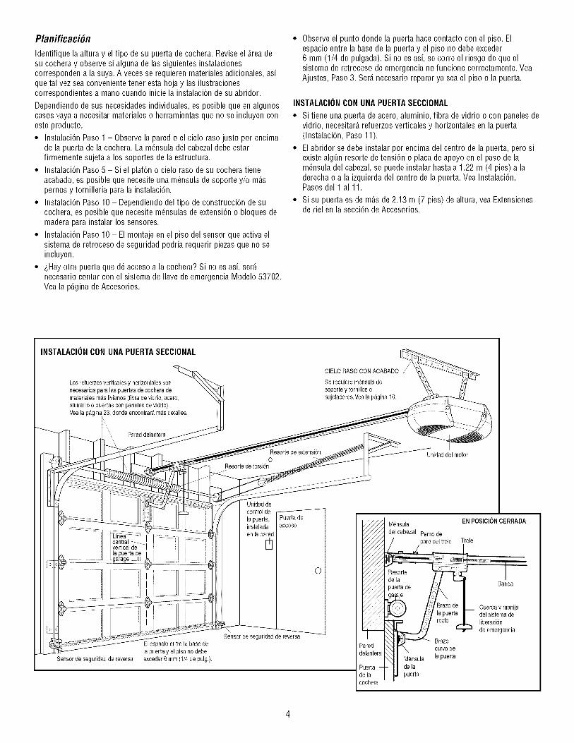
Planificaci6n
Identifique la altura y el tipo de su puerta de cochera. Reviseel Areadesu cochera y observe si alguna de las siguientes instalacionescorresponden a la suya. A veces se requieren materiales adicionales, asique tal vez seaconvenientetener esta hoja y las ilustracionescorrespondientes a mano cuando inicie la instalaci6n de su abridor.
Dependiendo de sus necesidades individuales, es posible queen algunoscasos vayaa necesitar materialeso herramientas que no se incluyen coneste producto.
• Instalaci6n Paso 1 - Observe la pared o el cielo raso justo por encimade la puerta de la cochera. La m_nsula del cabezaldebe estarfirmemente sujeta a los soportes de la estructura.
• Instalaci6n Paso 5 - Si el plaf6n o cielo raso de su cochera tieneacabado,es posible que necesite una m_nsula desoporte y/o m_.spernos y tornilleria para la instalaci6n.
• Instalaci6n Paso 10 - Dependiendodel tipo de construcci6n de sucochera, es posible que necesite m_nsulas deextensi6n o bloques demadera para instalar los sensores.
• Instalaci6n Paso 10 - El montaje en el piso del sensor que activa elsistema de retroceso de seguridad podria requerir piezasque no seincluyen.
• &Hayotra puerta que d_ acceso a la cochera? Si no es asi, ser_.necesario contar con el sistema de Ilavede emergencia Modelo 53702.Vea la p_.ginade Accesorios.
Observe el punto donde la puerta hace contacto con el piso. Elespacio entre la basede la puerta y el piso no debe exceder6 mm (1/4 de pulgada). Si no es asi, se corre el riesgo de que elsistema de retroceso de emergencia no funcione correctamente. VeaAjustes, Paso3. Ser_.necesario reparar ya sea el piso o la puerta.
INSTALACIONCON UNAPUERTASECCIONAL
• Si tiene una puerta de acero, aluminio, fibra de vidrio o con paneles devidrio, necesitar_,refuerzos verticales y horizontales en la puerta(Instalaci6n, Paso 11).
• El abridor se debe instalar por encima del centro de la puerta, pero siexiste alg0n resorte de tensi6n o placa de apoyo en el paso de lam6nsula del cabezal, se puede instalar hasta a 1.22 m (4 pies) a laderecha o a la izquierda del centro de la puerta.Vea Instalaci6n,Pasos del 1 al 11.
• Si su puerta es de m_.sde 2.13 m (7 pies) de altura, vea Extensionesde riel en la secci6n de Accesorios.
INSTALACII)NCONUNAPUERTASECCIONAL
Los refuerzosverticalesy horizontalessonnecesariospara las puertas de eocheradematerialesma.slivianos(fibra de vidrio,acero,aluminioo puertas conpaneles de vidrio).Veala pagina 23, dondeencontraramasdetalles.
CIELO RASOCONACABADO
Serequiere mensuladesoportey tornillos osujetadores.Veala pagina 16.
Pareddelantera
Resorte de extensi6nO
Resorte de torsbn
Unidaddel motor
la puerta degarage._U
Unidaddecontrol de
la puerta,instalada
en la pa[_]d
de
acceso
Sensor de seguridadde reversa
Elespacio entrela base dela puerta y el piso no debeexceder6 mm (1/4 de pulg.).
Sensor de seguridadde reversa
O
_ ensula EN POSlClONCERRADA
del cabezal Pernode/////] / paro del trole Trole
///_ puerta de o_. | an a
je t '/\ I_///_1_ _ /o 'Brazode L Cuerdaymanija/_L_ _ /_ la puerta | del sistemade
_////,_ = /o/ recto ...-L. liberaci6n
_.._._J _ de emergencia• I_\ PT_ Brazo
_red _. _. curvode_lanteraI_ -- , -......... _" Mensula ia puerraJerta --I- de la_la puertabchera

Planificaci6n (continUa)INSTALACIONCON PUERTASDE UNASOLAPIEZA
• Generalmente una puerta de una sola piezano requiere refuerzosadicionales. Si usted tiene una puerta de material liviano y quierereforzarla, consulte la informaciCn respecto a puertas seccionales,contenida en InstalaciCn,Paso 11.
• Dependiendo del dise_o de su puerta, tal vez necesite piezasdemontaje adicionales para la mCnsulade la puerta (Paso 11).
Sin un sistema de retroceso de seguridad que funcione debidamente,al cerrar la puerta de la cochera se corre el riesgo de que laspersonas (yen particular los ni_os peque_os) sufran LESIONESGRAVESo INCLUSOLA MUERTE.
• El espacio entre la basede la puerta de la cochera y el piso NODEBEexceder 6 mm (1/4 de pulgada). De no ser asi, el sistema deretroceso de seguridad no va a funcionar debidamente.
• El piso o la puerta de la cochera se DEBE reparar para eliminareste espacio.
PUERTADEUNASOLAPIEZASIN CARRIL
Pared delantera
CIELO RASO CONACABADO
Se requieremensula desoy tornitlos o sujetadores.Veata p_tgina16.
Riel
Unidad del motor
J
Puerta deacceso
O
Sensor de seguridad
Elespacioentre la base de reversa
Senso}de seguridad lapuerta y el piso no debedede reversa exceder6 mm (1/4de pulg.).
Unidadde control de la puerta,instaladaen la pared
iredlantera
EN POSICIONCERRADA
Perno de paredel trole i Banda Trole
\Mensu,X I
Mensula _J II Id_ la pue_ l_ Cuerday manija
,.A""__ I ] del sistemade
'_ Brazlorecto Brazo ] liberacion.de
de la puerta i!!ratoa _3 emergenclaX_,_Puerta de curvo
la cochera
EN POSICIONCERRADA
Perno de pare Banda Trole
_deltrole t.... I ,._L_.._
',Mensula Brazode la I I _'% I
del cabezal puertacurv_ Riel
...... ,..... I_/J _Mensulade _Brazorlc_o I_cuerdaymanija///I la puerta , "'_'_" I del sistemade_/J , de la puerta i liberaciCn
,PaUeortcah_a _ de emergencia
de reversa

Inventariode la caja de cart6n
Su abridor viene empacado en una caja de cart6n que contiene el motory las piezasque se muestran en la siguiente ilustraci6n. Tome nota deque los accesorios depender_.ndel modelo que hayacomprado. Si faltaalguna pieza, revise con cuidado el material de empaque ya queenocasiones las piezasse atoran en el mismo.
Toda la tornilleria y las piezasnecesarias para el montaje e instalaci6n desu puerta se ilustran en la siguiente p_.gina.Conserve la caja y losmateriales de empaque hasta que la instalaci6n y el ajuste se hayanterminado.
Bot6nde control de la puerta
SECURITY.I,,¢
Controles remote de3 funciones (1)
Cubiertade la banda Trole
PoleaLoca
Secci6ndelantera ,/_
y
Unidad del motorcon dos lente
Mensuladel cabezal
Seccionescentral
y posteriordel riel
Banda
Mensulade la puerta
Mensulaen 'U'
Secci6ncurvadel
brazo de la puerta
Mensulaspara colgar
Mensulaspara los sensoresdelsistemade retrocesode seguridad(2)
ProtectorSysteme_Sensoresdel sistema deretrocesode seguridad(un ojo emisory un ojo receptor) conectadosa uncablede campana dedos conductores.Blancoy blanco/negro(2)
Cable de campanade 2 conductoresBlancoy blanco/rojo
Etiquetasdeseguridady
literatura Secci6n rectadel brazedela puerta

Inventario de piezas
Antes de la instalaci6n, organice todas las piezasen grupos como se muestra en la siguiente ilustraci6n.
TORNILLERIAY PIEZASPARAELMONTAJE
Resorte/ tuercadel trole (1)
Pemode
1/4-20xl-3/4 de pulg.(2)
@ @ @Tuercade Arandelade Tuercade
1/4-20de pulg.(2) 3/8 de pulg, (1) 3/8 de pulg, (1)
Flecha roscadadel trole (1)
Enlacemaestro (2)
Perno Ioco(1)
TORNILLERIAY PIEZASPARALAINSTALACION
Pernode coche
de 1/4-20xl/2 de pulg. (2)Tuercade mariposa1/4-20 de pulg. (2)
Tornillode cabeza cuadrada
de 5/16-9xl-5/8 de pulg,(2)
IIIIIIIIIII1 >Tornillode cabezacuadrada
de 5/16-18xl-7/8 de pulg. (2)
Perno de cochede 5/16-18x2-1/2de pulg,(2)
OAnillosujetador (3)
,1111111111 Perno hexagonalde 5/16-18x7/8de pulg. (4)
@Tuercade
5/16-18de pulg. (6)
Arandela de 5/16 de pulg, (7)
lllllllllllllllllllllllll Tornillo6ABx1-1/4de pulg. (2)
Taquetepara muro falso(2)
Manija
Grapasconaislamiento(30)
Tornillode 6-32xl pulg, (2)
Espaciador(2)
Pasadorde chaveta Pasadorde chaveta Pasadorde chaveta
de 5/16x1-1/2de pulg. (1) de 5/16xl de pulg, (1) de 5/16x1-1/4de pulg, (1)
Cuerda

MONTAJE, PASO 1Monteel fie/e instaleel trole
Noenciendani useel abridorhastaque Ilegueal pasode lainstalaci6ncorrespondiente,deotra maneracorreel riesgodecomplicarel procesode instalaci6n.
El riel delantero tiene una "ventana" cortada en el extremo de la puerta(vea la ilustracibn). El orificio que se encuentrapor encima de estaventana es robsgrande en /a parte superiorde/fie/que en /a parteinferior. Hay un orificio m_s pequefio que se encuentra a8.9 cm (3-1/2 depulg.) y estb cerca de la orilla del rieL Gire el rielposterior de manera que tenga un orificio similar cerca de la orillaopuesta, robs o menos a 12 cm (4-3/4 depulg.) del extremo.
1. Quite el brazo recto de la puerta, las m_nsulas paracolgar y elpasador de chavetaque viene empacado dentro del riel delantero yp6ngalos a un lado para usarlos en el Paso5 y 12 de la Instalaci6n.NOTA:Para no sufrir una LESIONal desempacarel riel, mueva concuidado el brazo recto de la puerta que estb almacenado dentro de laseccibn de rieL
2. Alinee las secciones del riel sobre una superficie plana exactamentecomo se indica y luego deslice los extremos m_.speque_os dentro delos m_.sgrandes. Las pesta_as que se encuentrana Io largo de loslados del riel se van a ajustar en su lugar.
Paraevitar QUESE PELLIZQUE,conserve los manos y dedos lejos delas juntas cuando monte el reil.
3. Coloque el motor sobre el material de empaque para proteger lacubierta del mismo y apoye el extremo posterior del riel encima. Paraque le resulte m_.sc6modo, ponga alg_n tipo de apoyo bajo elextremo delantero del riel.
4. Ponga en el riel un destornillador como tope temporal del trole a25 cm (10 pulg.) del centro del orificio de la polea Ioca, como seindica en la ilustraci6n.
5. Revise y cerci6rese de que haya4 cojinetes de desgaste dentro deltrole interno, estos cojinetes son de pl_.stico.Si los cojinetes se hansoltado durante el transporte, revise todo el material de empaque.Ponga los cojinetes de desgaste en su lugar como se indica.
6. Deslice el trole a Io largo del riel desde el extremo posterior hacia eldestornillador.
pequenoExtremo
Extremom_is
peque_o
Rieles posteriores(AL MOTOR)
_tornillador/_ Pesta_as
Ven!an!___Riel delantero
\/_/ (A LA PUERTA))rificio de _ ],_/
polea Ioca_$7r_
Extremom_is
peque_o
TroJeexterno

MONTAJE, PASO 2
Fije el riel a la unidadde/motor• 0oloque un perno de 1/4-20xl-3/4 de pulg. dentro del orificio de la
cubierta de protecci6n que se encuentra en el extremo posterior delriel, como se indica en la ilustraci6n. Apriete bien el perno con tuercade 1/4-20 de pulg. NO ajuste demasiado la tuerca.
• Quite dos pernos de la parte superior del motor.
• Ponga la m_nsula en 'U' sobre el motor con el lado piano haciaabajoy alinee los orificios de la m_nsula con los orificios de los pernos.Sujete con los pernos que quit6 antes.
• Alinee el riel con la parte superior del motor. Desliceel extremo delriel en la m_nsula en 'U', hasta los topes que sobresalen en la parlesuperior y a los lados de la mbnsula.
Use SOLOel perno y la tuerca que vienen montados en la partesuperior del abridor para evitar que el abridor de la puerta de cocherase dafie SERIAMENTE.
Mensula en 'U'
Perno
Orificiopara iel pernoenla cubierta
de proteeci6n
Perno_. Ruedadentada del motor
ESTAS PIEZASSE IVlUESTRANEN SU TAIVlA_IOREAL
Q_ Tuercade
Perno de 1/4-20xl-3/4 de pulg. 1/4-20de pulg.
i DESLICEELRIEL HASTAiLOSTOPESQUE ESTANEN
iI_ LAPARTESUPERIORY A LOSi LADOSDELA MENSULA
Tuerca
MONTAJE, PASO 3
Instale la polea Ioca• Colocar la banda a un lado del riel, tal como se muestra. Introducir
por la abertura el extremo con el gancho de conexi6n al carro y pasaraproximadamente unas 30 cm (12 pulg.) de banda hacia el otro lado,con el lado de las nervaduras hacia el riel. Dejarla asi hasta el paso 5de Montaje.
• Quite la cinta de la polea guia. El interior del centro deberia estarengrasado. Si asi no fuera, lubriquelo nuevamente.
• Instale la polea en la abertura, tal como se muestra en la ilustraci6n.
• Haga pasar el perno eje por el riel y la polea, coloc_.ndolodesdearriba. Ajuste la tuerca de presi6n de 3/8 de pulg. hasta que laarandelade presi6n quede totalmente comprimida.
• Hagagirar la polea guia para asegurarsede que se mueva libremente.
• Coloque un perno de 1/4-20 x 1-3/4 de pulg. en el agujero del tope delcarro ubicado en el frente del riel, tal como se muestra en lailustraci6n. Aj_stelo firmemente con una tuerca de presi6nde 1/4 de pulg.-20.
Conectordel trole
Perno
Perno
Orificiode
paro del troleq
Engraseel interior \\
de la polea
PoleaIoca
Polea Ioca _"-TuercaI
Perno Ioco
ESTAS PIEZASSE [VlUESTRANEN SU TA[VlA_IOREAL
Perno de 1/4-20xl-3/4 de pulg. Tuercade
1/4-20 de pulg.Tuercade
3/8 de pulg.
Arandelade
3/8de pulg.

MONTAJE, PASO 4
Instale la banda y sujete el ret_n de/a cubiertade la banda
1. Jale la banda alrededor de la polea Ioca hacia el trole. El/adoacanaiadodebe estar en contacto con ia polea.
2. Engancheel conectador del trole en la ranura de retenci6n que seencuentra en eltrole como se indica en la ilustraci6n.
3. Ponga el trole contra las pinzasy alimente el resto de la bandaa todoIo largo del riel hacia la unidad del motor y alrededor de la ruedadentada. Los dientes de la rueda dentada deben retener la polea.
4. Verifique que la banda no est_ torica y que el lado PLANOdel ejeroscado del trole est_ haciael reil. Con_cteloel eje roscado del trolleyal estab6n maestro, como aparence en la ilustraci6n:
• Ponga los pasadores de la barra del eslab6n maestro a trav6s delos orificios que se encuentran en el extremo de la banday por laflecha dentada del trole.
• Ponga la cubierta del eslab6n maestro sobre los pasadoresy m_.sall_.de las ranuras de los pasadores.
• Deslice el resorte de clip sobre la cubierta yen las ranuras de lospasadores hasta que ambos pasadores queden firmes y segurosen su lugar.
5. Inserte el eje roscado del trolley en el orificio del trole. Cerci6rese deque ia banda no est# torcioda y que el/ado PLANOdel eje roscado deltrolley est# hacia el reil.
6. Sostenga la banda en la flecha del trole a medida que atornilla latuerca de resorte manualmente en laflecha hasta que est_ bienajustada contra el trole. No use herramientas para hacer esto.
7. Quite el destornillador.
8. Coloque el ret_n de la cubierta de la bandasobre la rueda dentadadelabridor como se muestra en la ilustraci6n, y sujete la placa demontaje con los tornillo hexagonalesde 8x3/8 de pulg. que seincluyen.
Paraevitar posibles LESIONESGRAVESen los dedos causadasporlas partes m6viles del abridor de puerta de cochera:
• SIEMPREmantenga las manos lejos de la rueda dentada mientrasest6 funcionando el abridor.
• Fije bien el desplegador de cadenaANTES de operar el abridor.
ESTAS PIEZAS SE MUESTRAN
EN SU TAMANO NORMAL
Tornillohexagonal8x3/8de pulg. Resorte/ tuercadel trole
Resorte de clip __del enlace maestro
Tapadelenlace maestro
del trole
Orificio
. .--.Indentacio'_del perno Barr'a del
enlacemaestro
PoleaIoca
Coneotordel trole
Reten de la "_ Tornillohexagonalscubiertade _ 8x3/8de pulg.la banda
I I del motor
Placa de
montaje
10

MONTAJE, PASO 5
Fije la tensi6n de la banda
• Ponga la punta de un destornillador dentro de una de las ranuras delanillo de latuerca y suj_telo firmemente contra el trole.
• Ponga una Ilaveabierta de 7/16 de pulg en el extremo cuadrado. D_vuelta a la tuerca m_.so menos un 1/4 de su giro completo hasta quese suelte el resorte y el anillo de la tuerca quede contra el trole.
Esto fija el resorte a latensi6n 6ptima de la banda.
Yatermin#de armarsuabridordepuertade cochera.Lealessiguientesadvertenciasantesdecontinuara la secci6ndeinstalaci6n.
,atuercaillode
i
Extremocuadrado
Trole
Anillode latuerca Anillode la tuerca
t_1_ ANTES/1pulg.(2.5 cm)
SPUESDE SUELTE
1-1/4 depulg.(3.18 cm)
INSTALACION
INSTRUCCIONES IMPORTANTES PARALA INSTALACION
Para reducir el riesgo de una LESION GRAVE ola MUERTE:
1. LEAY SIGAAL PIEDELA LETRA TODASLAS INSTRUCCIONESPARA LA INSTALACION.
2. Instale el abridor de puerta de cochera SOLOsi la puerta de lacochera est,. debidamente balanceaday lubricada. Si la puerta noest,. debidamente balanceadaes posible que no retroceda cuandose requiera, Io que podria ocasionar una LESIONGRAVEoINCLUSOLA MUERTE.
3. TODASlas reparacionesde los cables, resortesy otras piezas lasDEBEIlevar a cabo un t_cnico especializadoen sistemas depuertas, ANTESde instalar el abridor.
4. Quite TODOSlos seguros y retire TODAS las cuerdas conectadasa la puerta de la cochera ANTES de instalar el abridor paradeevitar que se enreden.
5. Instale el abridor de la puerta de cochera a una distanciade 2.13 m (7 pies) del piso.
6. Monte la manija de liberaci6n de emergencia a una distancia de1.83 m (6 pies) del piso.
7. NUNCAconecte el abridor de la puerta de cochera a unafuente deenergia el_ctrica hasta que asi se indique.
8. NUNCAIleve puestos relojes, anillos ni ropa muy floja mientrasest_ instalando o dando servicio al abridor, pues podrian atorarseen la puerta de la cochera o en los mecanismos del abridor.
9. Instale el control de pared de la puerta de cochera:
• de manera que quede a la vista desde la puerta de la cochera.
• fuera del alcance de los ni_os y a unaaltura minima de5 pies (1.5 m).
• lejos de TODASlas partes m6viles de la puerta.
10. Coloque la calcomania que advierte sobre el riesgo deatraparsecerca del control de la puerta de la cochera, en la pared.
11. Coloque la calcomania que contiene la prueba de retroceso deseguridad y liberaci6n de emergencia a plena vista en la parteinterior de la puerta de la cochera.
12. AI concluir la instalaci6n, pruebe el sistema de retroceso deseguridad. La puerta DEBEretroceder al entrar en contacto con unobjeto de 3.8 cm (1-1/2 de pulg.) o bien con un pedazodemadera de 5x10 cm (2x4 pulg.) puesto piano sobre el piso.
11

INSTALACION, PASO 1
Determine d6nde va a insta/ar la m_nsulade/cabeza/
Paraevitar una posible LESIONGRAVEo INOLUSOLA MUERTE:
• La m_nsula del cabezal DEBEquedar R(GIDAMENTEsujeta alsoporte estructural en la pared delantera o en el cielo raso, de noser asi es posible que la puerta de la cochera no retroceda cuandose requiera. NO instale la m_nsula del cabezalen muros falsos.
• Se DEBENusar sujetadores paraconcreto si el montaje de lam_nsula del cabezal o del pedazode maderade5x10 cm (2x4 pulg.) se hace en mamposteria.
• NUNCAtrate deaflojar, mover ni ajustar la puerta de la cochera,los resortes, los cables, las poleas, las m_nsulas ni la tornilleria,pues TODAS estas piezasest_.nbajo una tensi6n EXTREMA.
• SIEMPREIlame a un t_cnico especializadoen sistemas de puertassi la puerta de cochera se pandea,se atora o si est,.desbalanceada.Una puerta de cochera que no est_ balanceadapuede no retroceder cuando se requiera.
El proceso de instalaci6n varia dependiendo de los diferentes tipos depuerta de cochera. Siga las instrucciones que correspondan a su puerta.
1. Cierre la puerta y marque la lineacentral vertical del interior de lapuerta.
2. ContinUemarcando esta linea hacia arriba hasta Ilegara la pareddelantera, por encima de la puerta.
Es posible instalar la m_nsula del cabezal hastauna distanciam_xima de 1.22 m (4 pies) a cada lado del centrode la puerta,pero tinicamente si un resortede torsi6n o un placa central deapoyose encuentraen el recorrido. Tambi_n cuandoel espacio esreducido,se puede instalar la m_nsula en el cielo rasoo plaf6n dela cochera (yea la p_gina 13). (Asimismo,se puede instalarinvertida sobre la pared si es necesario, esto le dar_aproximadamente1 cm (1/2 de pulg.) de espacio.)
Si necesita instalar la m_nsula del cabezalen un pedazode maderade5x10 cm (2x4 pulg.) (ya sea en la pared o en el techo), use tornillosde cabezacuadrada o pijas (no se incluyen) para sujetar el pedazodemadera a los soportes estructurales, como se indica aqui y en lap_.gina13.
Abra la puerta hasta el punto m_.salto de su recorrido como semuestra. Marque una linea horizontal que intersecte en la pareddelantera y adel punto m_.salto del recorrido:
• 5 cm (2 pulg.) por encima del punto m_.salto en el caso de puertasseccionales y puertas de una sola piezacon riel.
• 20 cm (8 pulg.) por encima del punto m_.salto en el caso depuertas de una sola piezasin riel.
A esta altura, el extremo superior de la puerta tendr_,suficienteespacio parasu recorrido.
NOTA:Si el nEimero total de centfinetros excede la altura disponibleen su cochera, use la altura m#xima posible o consulte la p#gina 13para la InstalaciSnen el cielo raso o plafSn.
Pared
delantera\
INSTALACIONOPCIONAL DELA McNSULA DEL CABEZAL
EN EL CIELORASO _,.
Cielo rasosin acabado
Uneacentralverticalde la
aje Pedazode maderade 5x10 cm (2x4pulg.)
Soportesdela estructura
Pareddelantera
Carril
Punto masaltodel recorrido
Puertaseccionalcon carrilcurvo
Pared delantera
J
Puertade una sola piezaconcarril horizontal
cm (2pulg.)
Carril
Punto masaltodel recorrido
Pareddelantera
m(8 pulg.)
Puerta ma$ alto
orrido
Tornilleriadelmontante
Puertade una sola piezasin carrihtornilleria del montante
Pareddelantera
Pivote
Puertade una pieza sin carrihtornilleria del pivote
12

INSTALACION, PASO 2
Insta/e /a m_nsu/a de/cabeza/
Lam_nsuladelcabezalsepuedefijar a laparedjustoporencimadelapuertadelacocherao enelcieloraso.Siga lasinstruccionesqueseanm_.sadecuadasparasu cochera.No instale la m_nsuladelcabezalenunmuro falso. Si va a fijar la m_nsuladelcabezala ladrillo omamposteria,asegziresedeutilizarsujetadoresde cemento(noseincluyen).
INSTALACII_NDE LA MENSULADELCABEZALEN LA PAREDDELANTERA
• Coloque la m_nsula sobre la linea central vertical con el borde inferiorsobre la linea horizontal, como se muestra en la ilustraci6n (con laflecha de la m_nsula apuntando hacia el techo).
• Marque los orificios de la m_nsula que van en lineavertical. Taladrelos orificios con una broca de 3/16 de pulgada y sujete la m_nsula alsoporte de la estructura con la tornilleria que se incluye.
ESTAS PIEZASSE MUESTRAN ENSUTAMA_IO REAL
de 5/16por 9xl-5/8 de pulgadas
Montajeen lapared
Orificios opcionalespara la instalacbn
Pareddelantera
Pedazodemaderade5x10 cm
(2x4 pulg.)
Lfnea ihorizontales
Puntomas alto del
recorridode la puertade la garaje
Linea centralvertical de la
puerta de garaje
•Tornillos de cabezacuadrada de
5/16x9x1-5/8de pulg.
Resortede la puerta
- Puertade la cochera -
Lineacentral
puerta de garaje
INSTALACII_NDE LA MENSULADELCABEZALEN ELCIELORASO
• Extienda la linea central vertical sobre el cielo raso como se muestraen la ilustraci6n.
• Coloque la m_nsula enel centro de la lineaa no m_.sde15 cm (6 pulg.) de la pared. Cerci6rese de que la flecha de la m_nsulaapunte haciael lado opuesto de la pared. La m_nsula puede serinstalada pegada al cielo raso cuando el espacio es muy reducido.
• Marque d6nde va a taladrar los orificios laterales.Taladre los orificioscon una broca de 3/16 de pulgada y fije la m_nsula firmemente alsoporte de la estructura con la tornilleria que se incluye.
Orificiospara la instalaci6nen eleielo raso
/--_" - Cielo raso conacabado -t / / __ __ t / Lineacentral
t t _ _ / _ vertical de la puerta de garaje
Uensula del t _cabezal
Maximo de 15 cm,
Resortede
la puerta cuadrada de
5/16xgx1-5/8de pulg.
-- Pared delantera--
13

INSTALACION, PASO 3
Coloque el rie/ en la m_nsula de/cabezal
NOTA:(Opcional) Con algunas instalaciones anteriores puede reutilizar laantigua m#nsula del cabezal con los dos espaciadores depl_stico que seincluyen en la bolsa de componentes. Coloque los espaciadores en elinterior de la m#nsula, a cada lado del riel, tal y como se muestra en lailustraciSn.
• Coloque el abridor sobre el piso de la cochera debajo de la m_nsuladel cabezal. Use el material de empaque como base para protegerlo.NOTA:Si el resorte de la puerta est_ obstruyendo, va a necesitarayuda. Otra persona tendr_ que sostener el abridor firmemente sobreun soporte temporal para permitir que el riel pueda librar el resorte.
• Coloque el extremo del riel delantero dentro de la m_nsula delcabezaly una ambos elementos con un pasador de chavetade 5/16 por 1-1/2 de pulg., como se muestra en la ilustraci6n.
• Suj_telos con un anillo sujetador.
. Pareddelantera
cabezal
-----.--Polea Ioca
Mensula 0delcabezal
Orifieio de
montaje
chavetaexistente
Espaeiador
Mensuladecabezalexistente
0
de montaje
OPCIONPARAALGUNASINSTALACIONESPREVIA
Puertadela cochera
Cajadel abridoro soporte temporal
ESTASPIEZAS SE MUESTRAN EN SUTAMA_IO REAL
oD0Pasador de chaveta de Anillosujetador5/16 por 1-1/2 de pulg.
14

INSTALACION, PASO 4
Coloque el abridor en posici6n
Siga las instruccionescorrespondientes al tipo de puerta de su cochera,como se muestra en la ilustraci6n.
PUERTASECCIONAL0 PUERTADE UNASOLAPIEZACON CARRIL
Un pedazode madera de 5x10 cm (2x4 pulg.) le ser_.de ayuda aldeterminar la distancia idealentre la puerta y el riel.
• Retire la espuma de embalaje.
• Ponga el abridor sobre la escalera; si la escalera no es Iosuficientemente alta, va a necesitar ayuda.
• Abra completamente la puerta y coloque el pedazode maderade 5x10 cm (2x4 pulg.) en la secci6n superior, de maneraque quededebajo del riel.
• Si el panel superior golpea el trole al levantar la puerta, tire haciaabajo el brazo de liberaci6n del trole paradesconectar las seccionesinterna y externa del mismo. Deslice el trole externo hacia el motor. Eltrole puede permanecer desconectado hasta el final del Paso 12 de lasecci6n de Instalaci6n.
Paraevitar que la puerta de cochera sufra daSos,apoye el rieldel abridor de la misma sobre un pedazode maderade5x10 cm (2x4 pulg.) colocado en la secci6n superior de la puerta.
Riel
'_ Puerta El pedazode maderade 5x10 cm (2x4 pulg.)
I I se utilizapara determinarla distanciacorrectade instalacbn desdeel techo.
CONECTADO
PUERTADEUNASOLAPIEZASIN CARRIL
Coloque un pedazo de maderade 5x10 cm (2x4 pulg.) sobre su lado deayuda al determinar la distancia idealentre la puerta y el riel.
• Retire la espuma de embalaje.
• Ponga el abridor sobre la escalera; si la escalera no es Iosuficientemente alta, va a necesitar ayuda.
• Abra completamente la puerta y coloque un pedazode madera de5x10 cm (2x4 pulg.) sobre su lado en la secci6n superior, de maneraque quede debajo del riel.
• La parte superior de la puerta debe estar alineada con la partesuperior de la unidad del motor. No instale el abridor a m_.sde10 cm (4 pulg.) por encima de este punto. i
IJ Mensu,a ili
Elpedazo de maderade5x10 cm (2x4 pulg.) seutiliza para determinarla distanciacorrectade instalaci6ndesdeel techo.
15

INSTALACION, PASO 5
Cue/gueel abridorAqui se muestran tres ejemplos distintos para la instalaci6n; sinembargo, es posible que su cochera no concuerde con ninguno de ellos.Las m_nsulas de soporte deben estar en _.ngulo(Figura 1), para queproporcionen un soporte rigido. En caso de tener un cielo raso acabado(Figura 2 y Figura 3), instale una m_nsula de metal resistente en alg_nsoporte de la estrucura antes de instalar el abridor. No se incluye estam_nsula ni latornilleria.
1. Mida la distancia desde cada lado de la unidad del motor hasta elsoporte de la estructura.
2. Corte las dos partes de las m_nsulas colgantes a la medida adecuada.
3. Taladre los orificios de 3/16 de pulgada en los soportes de laestructura.
4. Fije un extremo de cada m_nsula al soporte con tornillos de cabezacuadrada de 5/16 -18xl-7/8 de pulg.
5. Fijeel abridor alas m_nsulas colgantes con pernos hexagonales de5/16 -18x7/8 de pulg., y sus tuercas y arandelas correspondientes.
6. Verifique que el abridor est_ centrado sobre la puerta (o alineado conla m_nsula del cabezal, si la m_nsula no est,. centradasobre lapuerta).
7. Quite el pedazode madera de 5x10 cm (2x4 pulg.). Hagafuncionar lapuerta manualmente. Si la puerta golpeael riel, suba la m_nsula delcabezal.
NOTA:NOconecte el abridor a la fuente de energfa el#ctrica en estemomento.
ESTAS PIEZASSE NIUESTRANENSUTAMA_IO REAL
Tornillo de cabezacuadrada
de 5/16-18xl-7/8 de pulg.
Pernohexagonalde 5/16-18x7/8de pulg.
Tuerca de
5/16-18de pulg. Arandelade 5/16de pulg.
Paraevitar la posibilidad de una LESIONGRAVEsi se cae el abridorde la puerta de cochera, suj6telo FIRMEMENTEa los soportesestructurales de la cochera. Se DEBENusar sujetadores para concretosi alguna de las m_nsulas se va a instalar en mamposteria.
Figura1
la estruotura
Mida la ',distancia
Pernosde ,5/16-18x7/8de pulg. ,,Arandelasde
5/16 depulg.Tuercasde
5/16-18de pulg.
Tornillosde cabezacuadradade5/16-18xl-7/8 de pulg.
Figura2
Soporte de la , _ _estructurano visible _ _ - -
Mensula(no se incluye) _ _
;;%o osd c, ,oo socoo c ° ooI cabezacuadrada_
Pernosde _ co
5/16-18x7/8de pulg.Arandelasde5/16 deTuercasde
5/16-18de pulg.
de 5/16-18xl-7/8 de pulg. _- _"
(No seincluyen)......... Pernosde
5/16-18x7/8de pulg.Arandelasde 5/16 de pulg.Tuercasde 5/16-18de pulg.
Figura3
(No se incluyen)Pernosde
_.__. 5/16-18x7/8de pulg.Arandelasde 5/16 de pulg.
Pernosde Tuercasde 5/16-18de pulg.5/16-18x7/8de pulg.
5/16 de pulg.Tuercasde5/16-18de pulg.
16

INSTALACION, PASO 6
Insta/e /a Contro/de /a Puerta
Ubique el control de la puerta de manera que quede a la vista desde lapuerta y a una altura minima de 1.5 m (5 pies) donde los niSospequeSosno Io puedan alcanzary lejos de las partes m6viles de lapuerta y de latornilleria.
1. Pele 6 mm (1/4 de pulg.) del extremo del cablede campana ycon6ctelo alas terminales de tornillo correspon-dientes al color delcable en la parte posterior de la puerta de la unidad de control; blancoa 2 y blanco y rojo a 1.
2. Sujete firmemente el bot6n de control de la puerta con tornillos de6ABx1-1/2 de pulg. Si se va a instalar en un muro falso, taladre dosorificios de 5/32 de pulg. y use los sujetadores que se incluyen.
3. Corra el cablede campana al motor a Io largo de la pared y el techo,use grapas con aislamiento en varios puntos a Io largo del cable parasujetarlo. Tenga cuidado de no perforar el cable al engraparlo, creandoasi un corto circuito o un circuito abierto.
4. Conecte el cable de campana alas terminales de conexi6n r_.pidadelpanel de la unidad del motor: blanco al blanco; blanco/rojo al rojo.
5. Coloque el cable de la antena como se indica.
6. Usetachuelas o grapas para sujetar permanentemente la calcomaniade advertencia sobre el riesgo de quedar atrapado; esta calcomaniadebe estar en la pared y cerca del control de la puerta. Lacalcomaniade advertencia de la prueba de retroceso de seguridad y liberaci6nmanual debe colocarse en un punto prominente del interior de lapuerta de la cochera.
NOTA: NOconecte el abridor a la energfa elbctrica ni Io haga funcionaren este momento. El trole har# el recorrido hasta Ilegar a la posiciSncompletamente abierta, pero no regresar# a la posiciSn cerrada hastaque el rayo del sensor est# conectadoy alineado debidamente.
Para evitar la posibilidad de una LESIONGRAVEo INCLUSOLAMUERTEpor electrocuci6n:
• ANTESde instalar el control de la puerta, cerci6rese de que laenergia el6ctrica no est6 conectada.
• Conecte el control SOLOa cables de bajo voltaje de 24 VOLTIOS.
Para evitar la posibilidad de una LESIONGRAVEe INCLUSOLA MUERTEcuando la puerta de la cochera se est,. cerrando:
• Instale el control de la puerta de manera que quedea la vista desdela puerta de la cochera, fuera del alcance de los niSos a una alturaminima de 1.5 m (5 pies), y alejado de las partes m6viles de lapuerta.
• NUNCApermita que los niSos haganfuncionar o jueguen con losbotones de control de la puerta ni con los transmisores de controlremoto.
• Hagafuncionar la puerta SOLOsi la puedever claramente, si lapuerta est,. debidamente ajustada, y si no no hay ningunaobstrucci6n en su recorrido.
• SIEMPREtenga a la vista la puerta de la cochera hasta que est6completamente cerrada. NUNCApermita que alguien se atraviese enel recorrido de la puerta de la cochera cuando se est,. cerrando.
ESTAS PIEZASSE MUESTRAN ENSU TAMA_IO REAL
Bot6nde control de la puerta Sujetadorespara6ABx 1-1/2pulg. rnurofalso
Grapasconaislamiento
I/ _4_C_-_I campanaTornillos /_ _..,Jterminales _
(VISTAPOSTERIOR)BOTONDECONTROLDE LAPUERTA
Terminalesdeconexi6n r_
Parasoltar o insertir el cable,
empuje la lengQetahaciadentro con la punta deun destornillador Rojo_
Pele el cable
11 mm (7/16 de pulg.)
puerta
Blanco GrisAntena
17

INSTALACION, PASO 7
Instale /as luces
• Oprima las lengiJetasde liberaci6n a ambos lados de la lente. Rote lalente suavemente haciaatr_.sy hacia abajo hasta que la bisagra quedeen la posici6n totalmente abierta. No quite la lente.
• Instale bombillos de 100 vatios como m_.ximoen cada portal_mpara.Los bombillos deben ser de A19 cuello standard s61o.En cuanto seconecte la electricidad, las luces se ENCENDERANy permanecer_.nencendidas por aproximadamente cuatro minutos y medio; luego lasluces se APAGAN.
• Invierta el procedimiento para cerrar la lente.
• Para reemplazo uso los bombillos parael abridor de puerta decochera deA19, estandar.
NOTA:$51outilice bombillos est_ndar. El uso de bombillos de cuello
corto o especiales puede sobrecalentar el panel o la portalbmpara.
Paraevitar un posible SOBRECALENTAMIENTOdel portabombillas:
• NO utilice bombillas de cuello corto ni de tipo especial.
• NO utilice bombillas hal6genas. Utilice SOLObombillasincandescentes.
Paraevitar daSoal abridor:
• NO utilice bombillas m_.sgrande que 100W.• SOLOutilice bombillas de tama_o A19.
Lengeetade liberaci6n
Bombillo estandarde 100 vatios --
(maximo)
//
Bombillo estandarde 100vatios
(maximo)
Bisagrade la lente
INSTALACION, PASO 8
Coloque la manija y la cuerda de emergencia
• Pase un extremo de la cuerda a trav_s del orificio que se encuentraen la parte superior de la manija roja de maneraque la palabra"NOTIOE"(aviso) sea legible, como se indica en la ilustraci6n.AsegQrelacon un nudo por Io menosa 2.5 cm (1 pulg.) del extremode la cuerda para evitar que se resbale.
• Pase el otro extremo de la cuerda a trav6s del orificio del brazo deliberaci6n del trole exterior.
• Ajuste el largo de la cuerda de tal maneraque la manija quede a1.83 m (6 pies) del piso. haga un nudo paraasegurarla. Paraevitarque la cuerda o la manija se enganche enalgo, aseg_rese de que notoquen el techo de ning_n vehiculo.
NOTA:Si es necesario cortar /a cuerda, queme con un cerillo o unencendedor el extremo que cort5 para sellarla y evitar que se desenrede.
Paraevitar la posibilidad de una LESIONGRAVEo INOLUSOLAMUERTEsi la puerta de la cochera se cae:
• De ser posible, use la manija de emergencia parasoltar el troleSOLOcuando la puerta de la cochera est_ CERRADA.Si losresortes est,. d_biles o rotos, o bien si la puerta est,.desbalanceada,la puerta abierta podria caerser_.piday/oinesperadamente.
• NUNCAuse la manija deemergencia a menos que la entradaa lacochera est_ libre de obstrucciones y no haya ninguna personapresente.
• NUNCAuse la manija para tirar de la puerta paraabrirla o cerrarla.Si el nudo de la cuerda se suelta, usted podria caerse.
Trole
I
I _den __///__
Manijade.___ .:_ Nudo
emergencia k),_,-"
18

INSTALACION, PASO 9
Requisites para la instalaci6n el_ctrica
Para evitar dificultades conla instalaci6n, no encienda ni use elabridor en este memento.
Para reducir el riesgo de cheque el_ctrico, su abridor para puerta decochera viene con una clavija de conexi6n a tierra de tres patas. Estaclavija s61ose puedeconectar a una toma de corriente puestaa tierra ycon tres entradas. Si la clavija no entra en la toma de corriente que ustedtiene, dirijase a un electricista profesional para que le instale latoma decorriente correcta.
CORRECOINCORREO
Paraevitar la posibilidad de una LESIONGRAVEo INCLUSOLAMUERTEper electrocuci6n o incendio:
• Cerci6rese de que el abridor no est_ conectado a la energiael6ctrica, y desconecte la alimentaci6n el_ctrica al circuito ANTESde quitar la cubierta paraestablecer la conexi6n del cableadopermanente.
• Tanto la instalaci6n come el cableado de la puerta de cocheraDEBENcumplir con TODOSlos c6digos localesde construcci6n yel_ctricos.
• NUNCAuse una extensi6n ni un adaptador de dos hilos, tampocomodifique la clavija para poder enchufarla. Aseg_rese de que elabridor est_ puesto a tierra.
CONEXIONCONCABLEADO PERMANENTE
Si la reglamentaci6n local exige que su abridor tonga cableadopermanente, siga los siguientespasos.
Paraconectar el abridor a la corriente el_ctrica de forma permanente atrav6s del orificio de 7/8 de pulg. Iocalizadoen la parte superior delmotor:
• Quite los tornillos de la cubierta de la unidad del motor y deje lacubierta a un lade.
• Quite el cablede tres entradas.
• Conecte el cable negro (linea) al tornillo de laterminal de cobre, elcable blanco (neutral) al tornillo de la terminal color plata, y el cableverde (tierra) al tornillo verde de la puestaa tierra. El abrider debeestar puesto a tierra.
• Vuelva a poner la cubierta en su lugar y atornillela.
Para evitar dificultades con la inslalaci6n, ne encienda ni use elabrider en este memento.
LengQetade la tierra
\
Tornillo verde
de puestaa tierra
Cable atierra
Cable blanco
negro
Cable
negro
19

INSTALACION, PASO 10
Insta/e la Sistemade Protecci6n®
Elsensordelsistemaderetrocesode seguridaddebeestarinstaladoy alineadocorrectamente,antesdequeel abridordela puertadecocheramuevala puertahaciaabajo.
INFORMACIONIMPORTANTECON RESPECTOAL SENSORDELSISTEMADE RETROCESODESEGURIDAD
Si se instala y se alinea correctamente, el sensor del sistema deretroceso de seguridad detectar_,cualquier obst_.culoque se cruce en elrecorrido del rayo electr6nico. El ojo emisor (el que tiene la luzindicadora decolor _.mbar)envia un rayo electr6nico invisible al ojoreceptor (el que tiene la luz indicadora de color verde). Si alg_n objetoobstruyera este rayo invisible mientras la puerta se est,. cerrando, lapuerta se detendr_,autom_.ticamente,retroceder_,hasta abrirse porcompleto, y la luz del abridor parpadear_,diez veces.
Estos sensores se deben instalar en el interior de la cochera de manera
que el ojo emisor y el ojo receptor est6n uno frente al otro a amboslados de la puerta y a una distancia m_.ximade 15 cm (6 pulg.) del piso.Ambos sensores se pueden instalar en cualquiera de los dos lados de lapuerta, ya seael derecho o el izquierdo, siempre y cuando nunca le d6 elsol directamente a la lente del ojo receptor.
Las m6nsulas para la instalaci6n han sido dise_adas paraque se sujetendirectamente al carril de la puerta, sin la necesidadde tornilleria ni piezasadicionales.
Cerci6rese de que la energia el6ctrica no est6 conectadaal abridor dela puerta de la cochera ANTESde instalar el sensor del sistema deretroceso de seguridad.Paraevitar una LESIONGRAVEo INOLUSOLA MUERTEcuando la
puerta de la cochera se est,. cerrando:
• Conecte y alinee correctamente el sensor del sistema de retrocesode seguridad. Estedispositivo de seguridad es necesario y NOSEDEBEdesactivar.
• Instale el sensor del sistema de retroceso de seguridad de maneraque el rayo NO ESTI_a m_.sde 15 cm (6 pulg.) del piso.
Si es necesario instalar las unidades sobre la pared, aseg_rese de quetodas las m6nsulas est6n sujetas a una superficie s61ida,por ejemplo,uno de los soportes de la pared. Las m6nsulas de extensi6n est_.ndisponibles, si se necesitan (vea la secci6n de Accesorios). Siva ainstalar los sensores sobre ladrillo o mamposteria, use un pedazodemadera para evitar hacer orificios innecesarios sobre la mamposteria encaso que necesite cambiarlos de lugar.
El trayecto del rayo elecr6nico invisible debe estar libre de cualquierobstrucci6n. Ninguna de las partes de la puerta (los carriles, resortes,bisagras, rodillos, u otras piezaso tornilleria) debe interrumpir el rayocuando la puerta se est6 cerrando.
z/Sensor de seguridadde reversaauna distancia maxima
de 15 cm (6pulg.) del pisoAreade protecci6ndelrayoelectr6nico invisible
Sensor de seguridadde reversaaunadistancia maxima
de 15cm (6pulg.) del piso
Vistade la puertadesdeel interiorde la cochera
20

INSTALACIONDE LASMI_NSULAS
Aseg_rese de queel abridor no est_ conectadoa la corrienteel_ctrica.
Instale y alinee las m_nsulas de maneraque los sensores est_n unofrente al otro en los lados opuestos de la puerta,a una distancia m_.ximade 15 cm (6 pulg.) del piso. Instale las m_nsulas de una de las tresmaneras siguientes:
Instalaci#n en el carril de la puerta de la cochera (recomendada):
• Deslice los brazos curvos sobre la orilla redondeadade cada uno de
los carriles de la puerta, con los brazos curvos apuntando hacia lapuerta. Col6quelos en su posici6n contra el costado del carril. Debequedar ras, con el reborde pegado a la orilla posterior del carril, comose ilustra en la Figura 1.
Si el carril de su puerta no soporta la m_nsula firmemente, serecomienda que la instale sobre la pared.
Instalaci#n en la pared (Figura2 y 3):
• Coloque la m_nsula contra la pared con los brazos curvos apuntandohacia la puerta. Cerci6rese de que haya suficiente espacio para que elrayo del sensor no est_ obstruido.
• Si es necesario tener m_.sprofundidad, puede usar m_nsulas deextensi6n (vea Accesorios) o bloques de madera.
• Use los orificios de montaje de la m_nsula para marcar y taladrar los(2) orificios de 3/16 de pulgada de di_metro a cada lado de la puerta auna distancia m_.ximade 15 cm (6 pulg.) del piso.
• Fije la m_nsula a la pared con tornillos de cabezacuadrada (no seincluyen).
• Si est,. usando m_nsulas de extensi6n o bloques de madera por lafalta deespacio, aseg_rese deque las dos unidades queden a lamisma distancia de la superficie de montaje. Asimismo, aseg_rese deque no haya ninguna obstrucci6n.
Instalacidn en el piso (Figura 4):
• Use bloques de maderao m_nsulas de extensi6n (vea Accesorios)para elevar las m6nsulas de los sensores de manera que las lentesqueden a una distancia m_ima de 15 cm (6 pulg.) del piso.
• Cuidadosamente mida e instale las unidades derecha y izquierdaa lamisma distancia con respecto a la pared. AsegQresede que no hayaninguna obstrucci6n.
• Fijeal piso las m_nsulas para los sensores con los sujetadores paracemento, como se muestra en la ilustraci6n.
Figura 1
Carril de
III ,ap.e aI-LI _ Reborde
INSTALAClON EN ELCARRIL DE LA PUERTA(LADO DERECHO)
Luzindicadora
Figura2 INSTALAClON EN LA PARED(LADO DERECHO)
Fije el bloque de maderaa la paredcon
tornillosde cabezacuadrada (No se incluyen)
Luz
indicadora Mensula
_-_del sensor
_LJnie - -(N° st 'n_
cuadrada
Figura 3 INSTALAClON ENLA PARED (LADO DERECHO)
de extensi6n)
Figura4 INSTALACION EN EL PISO(LADO DERECHO)
ESTAS PIEZASSE MUESTRANEN SU TAMA_IO REAL
Perno de coche
de 1/4-20xl/2 de pulg.Tuerca de mariposa Grapas con1/4-20de pulg. aislamiento
l _ Usesujetadores
, H o pernos para' v concreto, ' (Nose incluyen)
Luzindicadora
del sensor
21

MONTAJEY CABLEADODELOSSENSORESDELSISTEMA DESEGURIDADDE REVERSA
• Deslice la cabezade un perno de coche de 1/4-20xl/2 de pulgadadentro de la ranura de los sensores. Usetuercas de mariposa parasujetar los sensores alas m_nsulas, con las lentes de cada sensorfrente a frente a ambos lados de la puerta.Cerci6rese de que laextensi6n de la m_nsula no obstruya las lentes (Figura 5).
• Apriete lastuercas de mariposa a mano.
• Lleve los cables de los dos sensores al abridor. Utilice grapas conaislamiento para sujetar el cable a la pared y al cielo raso.
• Pele 11 mm (7/16 de pulg.) del aislamiento en cada juego de cables.Separe los alambres blanco y blanco/negro los suficiente para quepueda conectarlos a las terminales de conexi6n r_.pidadel abridor, dela forma siguiente. Tuerza juntos los cables del mismo color. Insertelos cables en los orificios de conexi6n r_.pida:el blanco al blanco y elblanco/negro al gris (Figura 6).
CI_MOALINEARLOSSENSORESDESEGURIDADDEREVERSA
• Conecte el abridor; las luces del sensor emisory del sensor receptorse deben de encenderypermanecer encendidassi todas lasconexiones del cableado y la alineaci6n se han hecho correctamente.
La luz _.mbardel sensor que emite el rayo se encender# aunque est_obstruido o fuera de alineaci6n, pero si la luz verde del sensor receptordel rayo est,. apagada,parpadea o se ve baja, (y no hay ningunaobstrucci6n en el recorrido del rayo de luz invisible), ser_.necesarioalinearlos.
• Afloje la tuerca de mariposa del sensor emisor y reajuste el sensor.Apunte directamente al otro sensory apriete la tuerca de mariposa.
• Afloje la tuerca de mariposa del sensor receptor del rayo, y reajustehasta que reciba el rayo del sensor emisor. Una vez que la luz verdebrille continuamente, apriete la tuerca de mariposa.
Figura5
Tuercade mariposa
Perno de coche "__
de 1/4-20xl/2 de pulg.
DIAGNOSTICODEFALLASCON RESPECTOA LOSSENSORESDELSISTEIVIADESEGURIDADDEREVERSA
1. Si la luz verde del sensor que emite el rayo no permanece encendidadespu6s de la instalaci6n, verifique Io siguiente:
• El suministro de corriente el@trica al abridor.
• Que haya un corto circuito en alguno de los cables, ya seaelblanco, o el blanco/negro. Estoocurre frecuentemente donde hayalguna grapa.
• AIg_n error en la conexi6n de los cables de los sensores al abridor.
• AIgQncable roto.
2. Si la luz indicadora del sensor que emite el rayo enciende ypermanece encendida,pero la luz del otro sensor no enciende:
• Verifique que est6n correctamente alineados.
• Verifique que no haya un alambre roto en el cable del sensorreceptor.
3. Si la luz indicadora del sensor receptor esta d6bil o baja, verifique laalineaci6n de los sensores.
NOTA: Si la trayectoria del rayo invisible se ve obstruida o est# fuera dealineaciSn,al tratar de cerrar la puerta #sta se abrir# autom#ticamente. Sila puerta est#abierta, simplemente no se podr# cerrar, y las luces deabridor parpadearbn diez veces. Veala pbgina 20.
Figura6Cablede campana
Cielo raso conacabado
Conecteel cablealasterminalesde conexbn rapida
Cablede campana 1. Pele elcable11 mm (7/16de pulg.)
7/16de pulg (11 m_rl}
2. Tuerzajuntos loscablesdel mismocolor
Area de protecci6ndel
Sensor de seguridadde reversa rayoelectr6nico invisible
\,
Sensorde seguridadde reversa
3. Paraintroduciro soltar el
cable, empujela lengQetahaciadentro con la puntade un destornillador
Rojo Blanco Gris
Terminalesde conexi6nrapida
22

INSTALACION, PASO 11
Fije la m_nsula de la puerta
Sioa las instruccionesque correspondan al tipo de puerta de cochera queusted tenoa, como se muestra en la ilustraci6no en la p_.oinasiouiente.
Si usa un puntalhorizontal, _ste debe set Io suficientemente largopara sujetarlo a dossoportesverticales. Si usa un puntalvertical,_ste debe set de la altura del panel superior.
La ilustraci6n muestra una piezade hierro en _.ngulocomo puntalhorizontal. Parael puntal vertical se deben usar dos piezasde hierro en_.ngulocon objeto de crear un soporte en "U" (Figura 1). La mejorsoluci6n es ponerse en contacto con la compaSiafabricante de la puertade su cochera e informarse acercade los juegos de refuerzos de puertaspara la instalaci6n de un abridor.
NOTA: Muchas de las instalaciones con soporte o puntal vertical tomanen cuenta la instalaciSn directa de los pasadores de chavetay el brazo dela puerta. En este caso, no necesitar# instalar la m#nsula para la puerta;proceda al Paso 12.
PUERTASSECCIONALES
• Coloque la m_nsula para la puerta sobre la linea central vertical quehabia marcado previamente para la instalaci6n de la m_nsula delcabezal.Aseg_rese de que la leyenda "UP" (arriba) est6 en la posici6ncorrecta, como est,. indicado en la parte interior de la m_nsula(Figura 2).
• Coloque la m_nsula sobre la parte frontal de la puerta, dentro de loslimites siguientes:
A) El borde superior de la m_nsula 5-10 cm (2-4 pulg.) debajo delborde superior de la puerta.
B) La orilla superior de la m_nsula debe estar directamente debajode alg_n soporte de la estructura a Io largo de la parte superiorde la puerta.
En el caso de puertas de fibra de vidrio, aluminio o acero ligero, ESNECESARIOcolocar un refuerzoANTES de instalar el marco de la
puerta. P6ngaseen contacto con el fabricante de su puerta paraobtener un kit de refuerzo.
ESTAS PIEZASSE [VIUESTRANEN SU TA[VIA_IOREAL
de pulg. Arandelade 5/16 de pulg.
Pernode coche de5/16-18por2-1/2 de pulg.
• Marque y taladre dos orificios de 5/16 de pulg. para los sujetadores ala derecha y a la izquierda. Sujete la m_nsula al refuerzo vertical(si 6steexiste), como se muestra en la Figura 1.
Si el tipo de instalaci6n de su cochera no requiere refuerzos verticales,pero si necesita los orificios para los sujetadores de la m6nsula, taladre yfijelos como se muestra en la Figura 2.
Linea central
puerta de garaje
Mensuladelcabezal/ Si su puerta es de metal,aluminio,
fibra de vidrioo con panelesde vidrio,siempre son necesarios refuerzosverticales y horizontales.(No se incluyen)
Lineavertical de la
puerta de garaje
puerta odel refuerzo
(_e madera
I /
Mensulade
Pernode cochede 5/16-18x2-1/2de pulg.
Mensulade
ii
HACIAARRIBA
Arandela de ................... ,L
;---- 5/16 de pulg. Tuercade
5/16-18de pulg.ARRIBA
@@.
puerta_ra 2
Figura1
23

PUERTASDEUNASOLAPIEZA
Lea y respetetodas las advertencias e instrucciones respecto a losrefuerzos, contenidas en la p_.ginaanterior, Instalaci6n de puertasseccionales, ya que todos los refuerzos para su puerta de una solapiezason los mismos.
• Coloque la m_nsula de la puerta en el centro de la parte superior dela misma, alineada con la m_nsula del cabezal, segQnse indica en lailustraci6n. Marque ya sea los orificios derecho e izquierdo osuperior y inferior.
• Taladre los orificios piloto de 5/16 de pulg. y sujete la m_nsula conla tornilleria que se incluye.
Si la puerta no tiene un marco exterior expuesto, taladre dos orificiosde 3/16 de pulg. y sujete la m_nsula a la parte superior de la puerta contornillos de cabeza cuadrada de 5/16x1-1/2 de pulg. (no se incluyen).
NOTA: La m#nsu/a para /a puerta puede ser insta/ada sobre /a orillasuperior de/a puerta si es necesario para su insta/aciSnen particular.(Vea /a i/ustraciSn de co/ocaciSnopciona/, sefia/adacon/a/[neapunteada). Ta/adredos orificios de 3/16 depu/g. y sujete /a m#nsu/aa/a parte superior de/a puerta con total/los de cabezacuadradade 5/16x1-1/2 depu/gadas (no se inc/uyen).
ESTAS PIEZASSE [VIUESTRANEN SU TA[VIA_IOREAL
de pulg. Arandelade 5/16 de pulg.
Pernode coche de
5/16-18por2-1/2 de pulg.
Pared delantera
Maderade 5x10 cm(2x4pulg.)
-- Cielo raso conacabado --
Mensuladel cabezal
Colocaci6n
opcional, parala mensula
de la puerta
Mensulade
la puerta
Lineacentral
vertical de la
puerta de garaje
Si su puerta es de metal,aluminio,fibra de vidrio o con paneles devidrio, siempre son neeesariosrefuerzos verticales y horizontales(No se incluyen.)
Sisu puerta no tiene un marcoexteriorexpuesto,o encaso de que tenga querecurrir a la instalacbn opcional, usetornillosde cabezacuadradade 5/16x1-1/2de pulg.para sujetar la mensulade la puerta (Estostornillos no se incluyen.)
Arandela
de 5/16 de pulg.,,de 5/16-18 , Extremo
ide pulg. superior de la
_j puerta (interior
la "_de la cochera)
_@ Orilla superior
, "',.\ delapuerta
;' Colocacbn
opcional
Pernode coche
de 5/16-18por2-1/2de pulg.
24

INSTALACION, PASO 12
Conecte el brazo de la puerta al trole
8iga las instruccionesque correspondan al tipo de puerta de cochera queusted tenga, como se muestra a continuaci6n yen la p_.ginasiguiente.
SI)L0 PARAPUERTASSECCIONALES
0erci6rese de que la puerta de la cochera est_ completamente cerrada.Tire de la manija de emergencia para desconectar el trole exterior deltrole interior.Deslice el trole exterior hacia atr_.s(en direcci6n opuesta ala polea) por Io menos 20 cm (8 pulg.) como se indicaen lasFiguras 1, 2 y 3.
Figura 1:
• Fije la secci6n recta del brazode la puerta al trole exterior usando unpasador de chavetade 5/16xl pulg. Asegure la conexi6n con el anillosujetador.
• Fije la secci6n curva del brazoa la m_nsula de la puerta de la mismamanera, con un pasador de chavetade 5/16 por 1-1/4 de pulg.
Figura 2:
• Junte las dos secciones del brazo, Iocalizandodos pares de orificiosque se puedan alinear. Seleccionedos orificios que est_n tanseparados como seaposible para aumentar la rigidez del brazode lapuerta.
Figura 3, Opcionespara alinear los orificios:
• En caso deque los orificios del brazo curvo no se puedan alinear conlos orificios del brazo recto, desconecteel brazo recto y corteaproximadamente 15 cm (6 pulg.) del extremo que no tiene orificios.Vuelva a conectarlo al trole, con el extremo cortado hacia abajo, comose muestra.
• Junte las dos secciones de los brazos.
• Localice dos pares de orificios de ambas secciones que se puedanalinear y _nalos con tornillos arandelas y tuercas.
Tire de la manija de emergencia hacia el abridor en un _.ngulode 45grados, de manera que el brazo de liberaci6n del trole est_ en posici6nhorizontal. Proceda a la secci6n deAjustes, Paso 1, en la p_.gina27. Eltrole volver_,a estar listo autom_.ticamente,cuando se opere el abridor.
Figura1
Figura2
Polea
/ [{__._C',Lomenos20cm ',
(8pulg.)------_',
Pernodetope/ I I ',1-T \ Troledel trole / Trole J J , _n_ exterior
/ interi°rl I t"J,JAnillo I°1 _ Pasadorde chavetasujetador I°l II de 5/16xl de pulg.
/ lilZManijade
O Mensulade iol_ emergencia
_ la puerta _ Brazo
\ ,,/_,_ recto
r_,__ " Brazocurvo
" Pasadorde chaveta
de 5/16xl-1/4 depulg.
Polea
', Lomenos20cm ',,.[.,__(8 pulg.)----.}:
Perno detope / / _
del trole /
't
Arandelas /to]de5/16/o/
Tuercasde de pulg. /o/
5/16"18de pulg@ | /o°/
Mensulade la puerta
Pernos de5/16-18x7/8de pulg.
ESTAS PIEZASSE MUESTRANEN SU TAMA_IO REAL
,uer ade n,,,osu,etadOr5/16-18 de pulgada
O] _ O I Perno
Pasadorde chaveta de Pasadorde chaveta de hexagonalde
5/16xl de pulg. (para el trole) 5/16xl-1/4 de pulg. (para 5/16-18x7/8la mensulade la puerta) de pulgada
Figura3
Polea
', Lomenos20cm
_ q,'_(8 puig.)----)=
T_le6_ d_ pulg" /y
de pulg._ _?_. --
25

TODASLASPUERTASDEUNASOLAPIEZA
1. Arme el brazode/a puerta, Figura 4:
• Sujete las dos secciones de los brazos de la puerta (recto y curvo)a la mayor distancia posible, de manera que dos o tres de losorificios se sobrepongan uno al otro.
• Cierre la puerta y fije la seccien recta del brazo a la mensula de lapuerta con el pasadorde chavetade 5/16x1-1/4 de pulgada.
• Aseg_relos con un anillo sujetador.
2. Procedimiento de ajuste, Figura 5:
• Si tiene una puerta de una sola pieza,deber_,ajustar los limites delrecorrido antes de conectar el brazode la puerta. Los tornillos deajuste del limite de recorrido se encuentran en el panel del ladoizquierdo, como se muestra en la ilustracien que apareceen lap_.gina27. Siga el procedimiento de ajuste que apareceacontinuacien.
• Ajuste de la puerta al abrirla: Disminuyael limite del recorridohacia ARRIBA
- Ajuste el tornillo paraajustar el limite del recorrido hacia ARRIBA,d_.ndole4 vueltas hacia la izquierda.
- Oprima el boten de control de la puerta. El trole deber_,ir hasta laposicien completamente abierta.
- Abra la puerta manualmente de manera que est6 paralelacon elpiso y suba el brazode la puerta al trole. El brazo de la puertadeber_,tocar el trole justo en la parte posterior del orificioconector. Consulte la ilustracien correspondiente al brazo de lapuerta y al trole en su posicien completamente abierta. Si el brazono se extiende Io suficiente, ajuste el limite del recorrido de lapuerta; cada vuelta completa del tornillo equivale a 5 cm (2 pulg.)del recorrido del trole.
• Ajuste de la puerta al cerrarla: Disminuyael limite del recorridohacia ABAJO
- Ajuste el tornillo paraajustar el limite del recorrido hacia ABAJO,d_.ndole4 vueltas completas hacia la derecha.
Mensulade lapuerta
_de puAnill° sujetadorTuercade
Arandela de 5/16-18
Ig. de pulg. _ _9]1
_razo recto / ___)-_ I /, //
chavetade ____ _ _O"] ///
de pulg_°l_xae/7 8 _ _/
Figura4 de pulg. Brazo curvo
- Oprima el boten de control de la puerta, el trole deber_,ir hasta laposicien completamente cerrada.
- Cierre la puerta manualmente y suba el brazo de la puerta al trole.El brazo de la puerta deber_,tocar el trole justo delante del orificioconector del brazo de la puerta. Consulte la ilustraciencorrespondiente al brazo de la puerta y al trole en su posiciencompletamente cerrada. Si el brazo queda detr_.sdel orificioconector, ajuste el limite del recorrido de la puerta; cada vueltacompleta del tornillo equivale a 5 cm. (2 pulg.) de recorrido deltrole.
3. Conecteel brazode la puerta al trole:
• Cierre la puerta y sujete el brazocurvo al orificio conector del trolecon el Qltimo pasador de chaveta.Es posible que necesite levantarun poco la puerta manualmente para poder hacer esta conexien.
• Asegure con un anillo sujetador.
• Opereel abridor durante un ciclo completo del recorrido. Si lapuerta pareceestar en cierto _.ngulo(hacia atr_.s)cuando est,.completamente abierta, como se muestra en la siguienteilustracien, disminuya el limite del recorrido haciaARRIBA hastaque la puerta quede paralelaal piso.
NOTA:AI establecer el Ifmite hacia arriba como se indica en la p_ginasiguiente, la puerta no debe tener una inclinaciSn "hacb atr_s" cuandoest# totalmente abierta, como se flustra abajo. Una ligera inclinaciSn hacbatr#s ocasionar# que la puerta se pandee innecesariamentey/o que laoperaciSn no sea uniforme al abrir o cerrar la puerta desde la posiciSntotalmente abbrta.
Figura5Trole interno
Trole interno
Puertaabierta Angulo de la puerta(incorrecto)
26

AJUSTES, PASO 1
Ajuste e//imite de/recorrido
AI ajustar el limite del recorrido de la puerta, se regula hasta qu6 punto_sta se detendr_,al abrir y al cerrar.
Para poner en marcha el abridor, oprima el bot6n de control de la puerta.Hagafuncionar el abridor durante un ciclo completo del recorrido.
• _,Lapuerta se abrey se cierra completamente?
• &La puerta se mantiene cerrada y no retrocede indebidamente cuandoest,. completamente cerrada?
Si su puerta pasaestas dos pruebas, no necesitar_,hacer m_.sajustes allimite del recorrido. Pero si no pasa la prueba de la retroceso, tendr_,queajustar el limite del recorrido (vea Ajustes, Paso 3, en la p_.gina29).
El procedimiento de ajuste se explica a continuaci6n: Lea elprocedimiento con cuidado antes de continuar con el Paso 2 de lasecci6n de Ajustes. Use un destornillador para hacer los ajustes al limitedel recorrido. Despu_sde Ilevar a cabo un ajuste, haga funcionarelabridor duranteun ciclo completodel recorrido.
NOTA:El abrir y cerrar la puerta varias vecesdurante el procedimiento deajuste puede causar que el abridor se sobrecaliente y al sobrecalentarsese apagar£ $51o espere quince minutos y contin_e con los ajustesnecesarios. Si algo interfiere con el recorrido de la puerta en sutrayectoria hacb arriba, #sta se detendr#. Peru si algo la obstruye en sutrayectoria hacb abajo (incluyendo un posible desnivel o desbalanceo), lapuerta retroceder£
CI]MO Y CUANDOAJUSTARLOSLIMITES
• Si la puerta no se abre completamente,pero abrepot Io menos1.5 m (5 pies): (Aumente el limite del recorrido hacia ARRIBA. D_vuelta al tornillo de
ajuste del limite haciaarriba, gir_.ndolo hacia la derecha. Cadavueltadel tornillo equivale a 5 cm (2 pulg.) del recorrido.
NOTA:Para evitar que el trole golpee el pemo de la cubierta deprotecci6n, mantenga una distancia mfi7imade 5 a 10cm (2 a 4 pulg.)entre el trole y el pemo.
• Si la puerta no se abre pot Io menos 1.5 m (5 pies):
Ajuste la fuerza del movimiento hacia ARRIBA de la puerta (abierta),como se indica en el Paso 2 de la secci6n de Ajustes.
• Si la puerta no cierra completamente:
Aumente el limite del recorrido hacia abajo. D_vuelta al tornillo deajuste del limite del recorrido hacia la izquierda, (direcci6n opuesta alas manecillas del reloj); cada vuelta del tornillo equivale a5 cm (2 pulg) del recorrido.
Si a_n despu6s de esteajuste y del trole contra m_nsula de la poleadel cable (p_.gina4), la puerta continua sin cerrar completamente,alargue el brazo de la puerta (p_.gina25) y disminuya el limite delrecorrido haciaabajo. •
• Si la puerta retrocedecuandoest_ en la posici#n completamentecerrada:
Disminuya el limite del recorrido hacia abajo. D_vuelta al tornillo deajuste del limite del recorrido hacia la derecha (direcci6n de lasmanecillas del reloj); cada vuelta del tornillo equivale a 5 cm (2 pulg.)del recorrido.
Si el sistema de retroceso de seguridad no se ha instaladodebidamente, las personas (y los nifios pequefios en particular)podrian sufrir LESIONESGRAVESo INCLUSOLA MUERTEcuando secierra la puerta de la cochera.
• El ajuste incorrecto de los limites del recorrido de la puerta de lacochera interferir_,con la operaci6n adecuadadel sistema deretroceso de seguridad.
• Si se ajusta uno de los controles (limites de la fuerza o delrecorrido), es posible que sea necesario ajustar tambi_n el otrocontrol.
• Despu6s de Ilevar a cabo cualquier ajuste, se DEBEprobar elsistema de retroceso de seguridad. La puerta DEBEretroceder alentrar encontacto con un objeto de 3.8 cm (1-1/2 de pulg.) dealtura (o bien un pedazode madera de 5x10 cm (2x4 pulg.)acostado) en el piso.
Paraevitar que los vehiculos sufran dafios, cerci6rese de que cuandola puerta est_completamente abierta haya espacio suficiente.
Pernode la cubierta de protecci6n
{---h]oo o o
Jl/
Panel del lado izquierdo Tornillospara elajustedel limite del recorrido
CALCOMANiADEAJUSTES
Si /a puerta retrocedeal cerrar y no hay ningunainterferenciavisibleen el ciclo de/recorrido:
Si la luces del abridor parpadean,esto significa que los sensores delsistema de retroceso de seguridad no est_.ninstalados, no est_.nalineados correctamente o hay alguna obstrucci6n. Vea la secci6n deDiagn6stico de fallas en la p_.gina22.
Pruebe la puerta paraverificar que no se doble ni se pandee.Tire dela manija de liberaci6n de emergencia,y abra y cierre la puertamanualmente. Si la puerta se pandea, Ilame a un t_cnico especializadoen sistemas de puertas. Si la puerta no pareceestar desbalanceadanise pandea,continue con el ajuste de la fuerza del movimiento haciaABAJO de la puerta (cerrada), como se indica en el Paso2 de de lasecci6n de Ajustes.
27
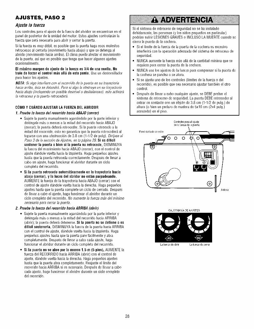
AJUSTES, PASO 2
Ajuste la fuerza
Los controles para el ajuste de la fuerza del abridor se encuentran en elpanel de posterior de la unidad del motor. Estos ajustes controlar_.n lafuerza que ser_.necesaria para abrir y cerrar la puerta.
Si lafuerza es muy d_bil, es posible que la puerta haga esos molestosretrocesos al cerrarla (movimiento hacia abajo) y que se detengaalabrirla (movimiento haciaarriba). El clima puede afectar el movimientode la puerta, asi que es posible que tenga que hacer algunos ajustesocasionalmente.
El m_ximomargen de ajuste de la fuerza es 3/4 de unavuelta. Notrate de forzarel controlm_s all_ de este punto. Use un destornilladorpara hacer los ajustes.
NOTA:Si algo interfiere con el recorrido de la puerta en su trayectoriahacia arriba, #stase detendr#. Pero si algo la obstruye en su trayectoriahacia abajo (incluyendo un posible desnivel o desbalanceo),esto activar#la retroceso y la puerta retroceder#.
COMOY CUANDOAJUSTARLA FUERZADELABRIDOR
1. Pruebe /a fuerza de/recorrido hacia ABAJO(cerrar)
• Sujete la puerta manualmente agarr_.ndolapor la parte inferior ydet_ngalam_.so menos a la mitad del recorrido haciaABAJO(cerrar); la puerta deber_,retroceder. Si la puerta retrocede a lamitad del recorrido, esto no garantiza que la puerta retroceder_,altoparse con una obstrucci6n de 3.8 cm (1-1/2 de pulg). Dirfjase alPaso 3 de la secciSn deAjustes, en la p#gina 29. Si es dificilsostener la puerta o bien si la puerta no retrocede, DISMINUYAlafuerza del movimiento haciaABAJO (cerrar), con el control deajuste d_.ndolevuelta hacia la izquierda. Haga peque_osajusteshasta que la puerta retroceda correctamente. Despu_s de Ilevar acabo un ajuste, haga funcionar el abridor durante un ciclocompleto del recorrido.
• Si la puerta retrocede autom_ticamenteen la trayectoriahaciaabajo (cerrar), y la luces del abridor no est_n parpadeando,AUMENTEla fuerza de la trayectoria haciaABAJO (cerrar) con elcontrol de ajuste d_.ndolevuelta hacia la derecha. HagapequeSosajustes hasta que la puerta complete un ciclo de cerrado. Despu_sde Ilevar a cabo el ajuste, haga funcionar el abridor durante unciclo completo del recorrido. No aumente la fuerzarobs del mfnimonecesario para cerrar la puerta.
2. Pruebe la fuerza del recorrido hacia ARRIBA (abrir)
• Sujete la puerta manualmente agarr_.ndolapor la parte inferior ydet_ngalam_.so menos a la mitad del recorrido haciaARRIBA(abrir); la puerta deber_,detenerse. Si la puerta no se detiene o esdificil sostenerla, DISMINUYA la fuerza de la puerta haciaARRIBAcon el control de ajuste, d_.ndolevuelta hacia la izquierda. HagapequeSosajustes hasta que la puerta pare f_.cilmentey abracompletamente. Despu_s de Ilevar a cabo cada ajuste, hagafuncionar el abridor durante un ciclo completo del recorrido.
• Si la puerta no se abre por Io menos 1.5 m (5 pies), AUMENTElafuerza del RECORRIDOhaciaARRIBA (abrir) con el control deajuste, d_.ndolevuelta hacia la derecha. Hagapeque_os ajusteshasta que la puerta abra completamente. Reajuste el limite delrecorrido haciaARRIBA si es necesario.Despu_s de Ilevar a cabocadaajuste, haga funcionar el abridor durante un ciclo completodel recorrido.
Si el sistema de retroceso de seguridad no se ha instaladodebidamente, las personas (y los niSos pequeSosen particular)podrian sufrir LESIONESGRAVESo INCLUSOLA MUERTEcuando secierra la puerta de la cochera.
• Si el limite de la fuerza de la puerta de la cochera es excesivointerferir_,con la operaci6n adecuadadel sistema de retroceso deseguridad.
• NUNCAaumente la fuerza m_.sall_.de la cantidad minima que serequiera paracerrar la puerta de la cochera.
• NUNCAuse los ajustes de lafuerza para compensar si la puerta dela cochera se pandeao se atora.
• Si se ajusta uno de los controles (limites de la fuerza o delrecorrido), es posible que sea necesario ajustar tambi_n el otrocontrol.
• Despu_s de Ilevar a cabo cualquier ajuste, se DEBEprobar elsistema de retroceso de seguridad. La puerta DEBEretroceder alentrar encontacto con un objeto de 3.8 cm (1-1/2 de pulg.) dealtura (o bien un pedazode madera de 5x10 cm (2x4 pulg.)acostado) en el piso.
Paneldel ladoderecho
Controlespara el ajustede la fuerza de la puerta
O O
®
CALCOMANiADE AJUSTES
La fuerza de abrir La fuerza de cerrar
28

AJUSTES, PASO 3
Pruebee/sistema de retrocesode seguridadPRUEBA
• Abra completamente la puerta, coloque un pedazode maderade 3.8 cm (1-1/2 de pulg.) (o un pedazode madera de5x10 cm (2x4 pulg.) acostado sobre el piso) en el centro de la puertade la cochera.
• Opere la puerta en la direcci6n haciaabajo. La puerta deber_retroceder autom_.ticamenteal hacer contacto con la obstrucci6n.
AJUSTE
• Si la puerta se detiene al toparse con la obstrucci6n, esto significa queel recorrido haciaABAJO (cerrar) no es suficiente. Aumente el limitedel recorrido haciaABAJO, con eltornillo correspondiente, haci_ndologirar 1/4 de vuelta hacia la izquierda.
NOTA:Si su puerta es seccional, asegElresede que los ajustes alIfinite no hagan que el brazo de la puerta se mueva m#s all# de unaposici6n recta haciaarriba y hacia abajo. Veala ilustraci6n en lap#gina 25.
• Repita la prueba.
• Si la puerta retrocede autom_.ticamenteal hacer contacto con elpedazode maderade 3.8 cm (1-1/2 de pulg.), quite la obstrucci6n yabra y cierre la puerta completamente por Io menos tres o cuatroveces paraverificar que el ajuste seaadecuado.
• Si la unidad sigue fallando la prueba del sistema de reversa deseguridad, Ilame a un t_cnico en sistemas de puertas.
VERIFICACI(_NIMPORTANTEDESEGURIDAD:
Compruebe el sistema de reversa de seguridad despu6s de que:
• Se haganajustes al largo del brazo de la puerta, los limites delrecorrido, o los controles de la fuerza.
• Se hagan reparacioneso ajustes a la puerta de la cochera (incluyendolos resortes y la tornilleria).
• Se hagan reparacionesal piso de la cochera porque est6 desnivelado,etc.
• Se hagan reparacioneso ajustes al abridor.
Si el sistema de retroceso de seguridad no se ha instaladodebidamente, las personas (y los niSos pequeSosen particular)podrian sufrir LESIONESGRAVESo INCLUSOLA MUERTEcuando secierra la puerta de la cochera.
• El sistema de retroceso de seguridad se DEBEprobar cada mes.
• Si se ajusta uno de los controles (limites de la fuerza o delrecorrido), es posible que sea necesario ajustar tambi6n el otrocontrol.
• Despu6s de Ilevar a cabo cualquier ajuste, se DEBEprobar elsistema de retroceso de seguridad. La puerta DEBEretroceder alentrar encontacto con un objeto de 3.8 cm (1-1/2 de pulg.) dealtura (o bien un pedazode madera de 5x10 cm (2x4 pulg.)acostado) en el piso.
[
_1 1/2de u
pig)(oun pedazo de maderade 5x10 cm(2x4pulg.) acostadosobre el piso)
AJUSTES, PASO 4
Pruebela Sistema deProtecciNP
• Oprima el bot6n de la unidad de control remoto para abrir la puerta.
• Coloque la caja de cart6n del abridor en latrayectoria de la puerta.
• Oprima de nuevo el bot6n de la unidad de control remoto para cerrarla puerta; 6sta no se deber_,mover m_.sde una pulgada2.5 cm (1 pulg.) y las luces del abridor empezar_.na parpadear.
La puerta no se podr_,cerrar con ninguno de los controles remotos si lasluces indicadoras de cualquiera de los sensores est_.napagadas(indic_.ndoleque los sensores est_.nfuera de alineaci6n, o que existealguna obstrucci6n).
Si el abridor cierra la puerta cuandoel sensordel sistema deretrocesode seguridadestziobstruido (y los sensoresno estzina mzisde 15 cm (6 pulg.) del piso), Ilame a un t_cnico especializadoensistemas de puertas.
Si el sensor de retroceso de seguridad no se ha instaladodebidamente, las personas (y los niSos pequeSosen particular)podrian sufrir LESIONESGRAVESo INCLUSOLA MUERTEcuando secierra la puerta de la cochera.
Sensorde seguridadde reversa Sensor de seguridadde reversa
29

OPERACION
INSTRUCCIONES IMPORTANTES DE SEGURIDAD
Para reducir el riesgo de LESIONES GRAVES o laMUERTE:
LEAY SIGATODASLAS ADVERTENCIASY LAS INSTRUCCIONES 8. NUNCAuse la manija para tirar de la puerta paraabrirla o cerrarla..
DEOPERACION.
2. SIEMPREconserve los controles remotos fuera del alcance de los
niSos. NUNCApermita que los niSos operen o jueguen con losbotones del control de la puerta de la cochera ni con los controlesremotos.
3. SOLOactive la puerta de la cochera siempre y cuando la pueda vercon claridad, est_ debidamente ajustaday no haya ningunaobstrucci6n en el recorrido de la puerta al cerrarse.
4. SIEMPREtenga la puerta de la cochera a la vista hasta que est6completamente cerrada. NADIEDEBEATRAVESAREL RECORRIDODELA PUERTACUANDOESTAENMOVIMIENTO.
5. NADIEDEBEPASARPOR DEBAJODELA PUERTASI ESTADETENIDAY PARCIALMENTEABIERTA.
6. De ser posible, use la liberaci6n de emergencia para soltar el troleSOLOcuando la puerta de la cochera est6 CERRADA.Si losresortes est_.nd_biles o rotos, o bien si la puerta est,.desbalanceada,puedeque la puerta se caiga r_.piday/oinesperadamente cuando est_ abierta.
7. NUNCAuse la manija de liberaci6n de emergencia a menos que laentradaa la cochera est_ libre de obstrucciones y no hayaningunapersona presente.
Si el nudo de la cuerda se suelta, usted podria caerse.
9. Si ajusta uno de los controles (limites de lafuerza o del recorrido),es posible que sea necesario ajustar tambi_n el otro control.
10. Despu6s de Ilevar a cabo cualquier ajuste, se DEBEprobar elsistema de retroceso de seguridad.
11. El sistema de retroceso de seguridad se DEBEprobar cada mes.La puerta DEBEretroceder al entrar en contacto con un objeto de3.8 cm (1-1/2 de pulg.) de altura (o bien un pedazo de madera de5x10 cm (2x4 pulg.) acostado) en el piso.
12. SIEMPREMANTENGALA PUERTADE LA COCHERA
DEBIDAMENTEBALANCEADA(vea la p_.gina3). Si la puerta noest,. debidamente balanceadapodria no retroceder cuando serequiera, Io que podria ocasionar una LESIONGRAVEo INCLUSOLA MUERTE.
13. TODASlas reparaciones necesariasen los cables, resortes y otraspiezas las DEBEIlevar a cabo un t_cnico especializadoen sistemasde puertas, pues TODAS estas piezasest_.nbajo una tensi6nEXTREMA.
14. SIEMPREdesconecte el suministro de energia el_ctrica al abridorde la puerta de la cochera ANTESde Ilevar a cabo cualquierreparaci6n o de quitar las cubiertas.
CONSERVEESTASINSTRUCCIONES.
C6moUsar suAbridorde Puerta de Cochera
Su abridor Security÷ _ y el control remoto manual han sidoprogramados en la f_.bricacon un c6digo coincidente que cambia cadavez que se usa, accesando al azar m_.sde 100,000 millones de c6digosnuevos. Su abridor funcionar_,hasta con 8 controles remotosSecurity÷ ®y un sistema de entrada sin IlaveSecurity+_L Si compra uncontrol remoto nuevo, o si desea desactivar alg_n control remoto, sigalas instrucciones que aparecenen la secci6n sobre C6mo programar elabridor.
Activesu aflridor de alguna de/as siguientes maneras:
• El Control remoto manual: Mantenga oprimido el bot6n grande hastaque la puerta se empiece a mover.
• El Control depared de la puerta: Mantenga oprimido el bot6n hastaque la puerta se empiece a mover.
• La Entrada sin Ilave (VeaAccesorios): Si su abridor de puerta decochera viene con este accesorio, deber_,estar programado antes deusarlo. Vea Programacidn.
Una vez activadoel aflridor (conel sensor de seguridad de retrocesocorrectamenteinsta/adoy a/ineado)
1. Si la puerta est,. abierta se va a cerrar. Si la puerta est,. cerrada se vaa abrir.
2. Si la puerta se est,. cerrando va a retroceder.
3. Si la puerta se est,. abriendo se va a detener.
4. Si la puerta se hadetenido en un punto parcialmente abierta, se va acerrar.
5. Sial cerrarse la puerta se top6 con alguna obstrucci6n, va aretroceder. Si la obstrucci6n interrumpe el rayo del sensor, las lucesdel abridor van a parpadeardurante cinco segundos.
6. Sial abrirse la puerta se top6 con alguna obstrucci6n, se va a detener.
7. Si la puerta est,. completamente abierta, no va a cerrar si el rayo est,.interrumpido. El sensor no tiene ning_n efecto en el ciclo de apertura.
Si el sensor no se ha instalado o est,. desalineado, la puerta no se cerrar_.con el control remoto manual. Sin embargo, la puerta se puede cerrarcon el Control de la puerta o la Entradasin Ilave,siempre y cuando losactive hasta que el recorrido haciaabajo hayaterminado. Si los sueltademasiado pronto, la puerta va a retroceder&
Las luces delabridorse encender_.nen los siguientes casos: Siempreque conecteel abridor inicialmente; cuando se restaura el suministro deenergia despu_sde una interrupci6n; cuando el abridor se activa.
Las luces se apagan autom_.ticamentedespu6s de4 minutos y 1/2 o sequedan encendidascuando se activa Luz en la consola de control dedetecci6n de movienmiento. Los bombillos deben ser de A19. El poder dela bombilla es 100 m_.ximode vatios.
La funci6n de la luz del Security+®: Las luces se encender_.ntambi_n sialguien camina por la puerta de la cochera cuando est,. abierta. Si tiene laconsola de control de detecci6n de movienmiento, estafunci6n puededesactivarse como sigue: Con las luces del abridor apagadas, oprima ymantenga oprimido el bot6n de la luz durante 10 segundos hasta que laluz se encienda y se apague de nuevo. Paravolver a activar estafunci6n,empiece el procedimiento con las luces encendidas, luego oprima ymantenga oprimido el bot6n de la luz durante 10 segundos hasta que laluz se apague y luego se encienda de nuevo.
3O
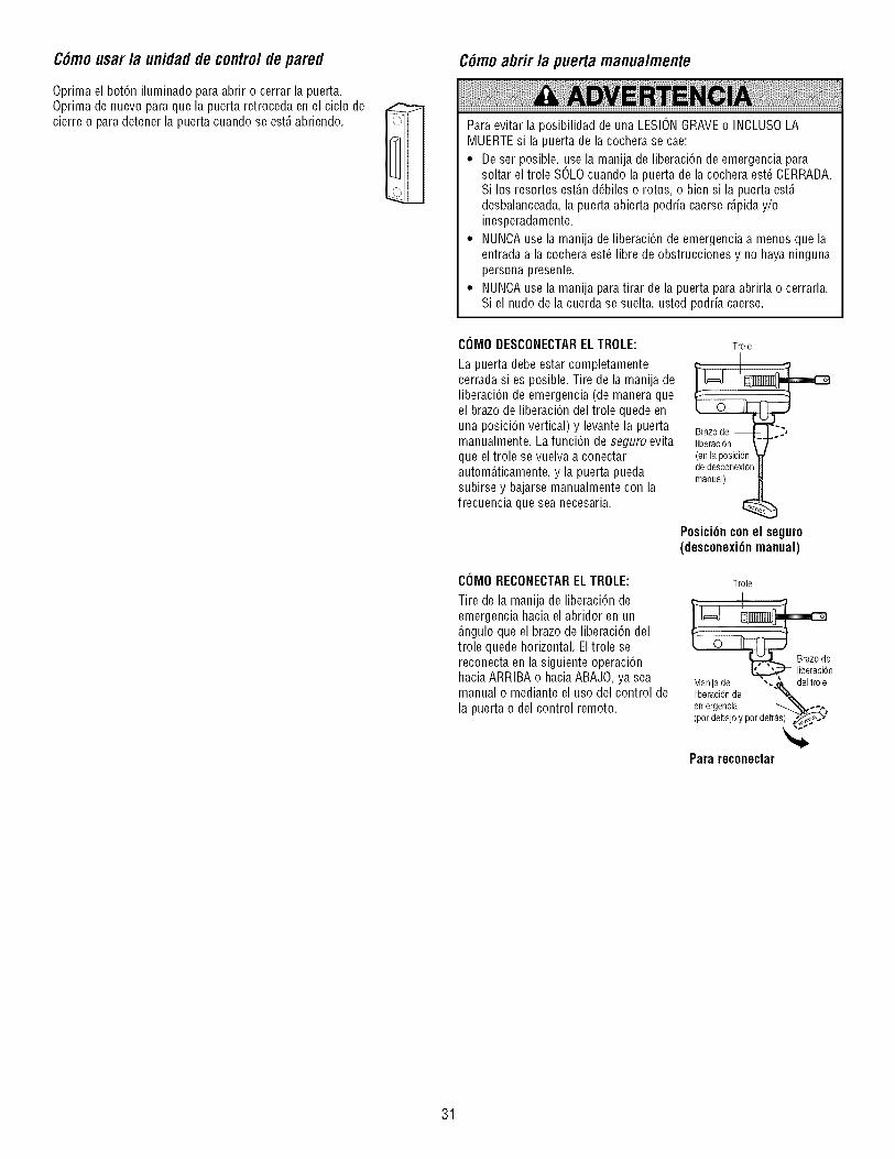
C6mousar la unidadde contro/depared
Oprima el bot6n iluminado paraabrir o cerrar la puerta.Oprima de nuevo paraque la puerta retroceda en el ciclo decierre o paradetener la puerta cuando se est,.abriendo.
C6moabrir la puerta manualmente
Paraevitar la posibilidad de una LESIONGRAVEo INCLUSOLAMUERTEsi la puerta de la cochera se cae:
• De ser posible, use la manija de liberaci6n de emergencia parasoltar el trole SOLOcuando la puerta de la cochera est_ CERRADA.Si los resortes est_.nd_biles o rotos, o bien si la puerta est,.desbalanceada,la puerta abierta podria caerser_.piday/oinesperadamente.
• NUNCAuse la manija de liberaci6n de emergencia a menos que laentrada a la cochera est_ libre de obstrucciones y no haya ningunapersona presente.
• NUNCAuse la manija para tirar de la puerta paraabrirla o cerrarla.Si el nudo de la cuerda se suelta, usted podria caerse.
COMODESCONECTARELTROLE:
La puerta debe estar completamentecerrada si es posible. Tire de la manija deliberaci6n de emergencia (de maneraqueel brazode liberaci6n del trole quede enuna posici6n vertical) y levante la puertamanualmente. La funci6n de seguro evitaque eltrole se vuelva a conectarautom_.ticamente,y la puerta puedasubirse y bajarse manualmente con lafrecuencia que sea necesaria.
CIJMORECONECTARELTROLE:
Tire de la manija de liberaci6n deemergencia hacia el abridor en un_.nguloque el brazode liberaci6n deltrole quede horizontal. El trole sereconecta en la siguiente operaci6nhacia ARRIBA o haciaABAJO, ya seamanual o mediante el uso del control de
la puerta o del control remoto.
Trole
de desconexidn
manual)
Posici6n con el seguro(desconexi6n manual)
Trole
_e
n
de "-._ del troleManijaliberaci6nde ",_-emergencia _,_ _-^
(por debajoy por detras)"' _'_o_2_. '
Para reconectar
31

MANTENIMIENTO DE SU ABRIDOR DEPUERTA DE COCHERA
AJUSTESDE LIMITEY FUERZA:
Las condiciones climatol6gicas puedenocasionar cambios menores en laoperaci6n de la puerta, los cuales van arequerir algunos reajustes, en particulardurante el primer a_o de operaci6n.
En las p_.ginas27 y 28 se encuentra lainformaci6n sobre los ajustes de limite yde fuerza. Lo _nico que necesita es undestornillador. Siga las instruccionescon cuidado.
Repita la prueba de retrocesodeseguridad(Ajustes, Paso 3, P_gina 29)
CONTROLES DE FUERZA
CONTROLES DE LIMITE
despu_sdehacerajustesa loslimiteso la fuerza.
CALENDARIODE iVlANTENliVlIENTO
Llna vez al mes
• Hagafuncionar la puerta manualmente. Si est,. desbalanceadao sepandea, Ilamea un t@nico especializado en sistemas de puertas.
• Revise para cerciorarse de que la puerta se abra y se cierrecompletamente. Ajuste los limitesy/o la fuerza de ser necesario (yealas p_.ginas27 y 28).
• Repita la prueba de la retroceso de seguridad. Hagalos ajustesnecesarios (veaAjustes, Paso3).
Una vez al a#o
• Ponga aceite en los rodillos, los cojinetes y lasbisagras de la puerta.El abridor no necesita lubricaci6n adicional. No lubrique los carriles dela puerta.
LA BATERIADELCONTROLREMOTO
Paraevitar la posibilidad de LESIONESGRAVESo incluso LAMUERTE:
• NUNCApermita que los niSos pequeSosest_n cerca delas baterias.
• Si alguien se traga una bateria, Ilame al m_dico de inmediato.
Para reducir el riesgo de incendio, explosi6n o combusti6n quimica:
• Reemplace UNICAMENTEcon baterias planas 3V2032.
• NO recargue, desarme, caliente por encima de 212 °F (100 °C) oincinere.
La bateria de litio puede durar hasta 5 a_os.
Paracambiar la bateria, useel broche delvisera o un destornillador paraabrir latapa,tal como se indica en la ilustraci6n. Coloquela bateria con el lado positivo hacia arriba (+).
Elimine las baterias usadas en formaadecuada.
Abra este extremo
primeroparaevitarque J (_ _'2_:_lacaja se ,_" _._d_/-'_-b_/j
agrle_
Reemplace la bateria _nicamente con baterias planas tipo 3V2032.
AVISO: Para cumplir con las reglas de la FCC y/o de Canada (IC), ajustes o modificaciones de este receptor I
y/o emisor estan prohibidos, excepto pot el cambio de la graduaci6n del c6digo o el reemplazo de la pila. NO I
HAY OTRAS PIEZAS REPARABLES DEL USUARIO. I
Se ha probado para cumplir con las normas de la FCC para USO DEL HOGAR O DE LA OFICINA. Laoperaci6n est,1 sujeta alas dos condiciones siguientes:(1) este dispositivo no puede causar interferencia Iperjudicial, y (2) este dispositivo debe aceptar cualquier interferencia recibida, incluyendo la interferencia que
puede causar una operac 6n no deseab e.
32

SI TIENE ALGUN PROBLEMA
1. La puertano cierra y las luces de la unidaddel motor parpadean:Elsensor del sistema de retroceso de seguridad debe estar instaladoyalineado correctamente paraque el sistema de apertura de la puertade la cochera se muevaen sentido descendente.
• Aseg_resede que los sensores de seguridad est6n instalados yalineados correctamente, y que est6n libres de obstrucciones.Oonsulte la secci6n Instalaci6n, Paso 10: Instale La Sistema deProtecciSn®.
• Compruebe los LED dediagn6stico de la unidad del motor para versi parpadean. Luego consulte la tabla de diagnSstico en lasiguiente p_.gina.
2. El controlremoto no activa la puerta:
• Vuelva a programar el control remoto seg_n las instrucciones.Consulte la secci6n sobre su programaciSn.
• Si el control remoto sigue sin activar la puerta, compruebe el LEDde diagn6stico de la unidad del motor para ver si parpadea; luegoconsulte/a tab/a de diagnSstico en la siguiente p_.gina.
3. La puerta invierte el movimientosin ninguna raz6naparente: ajustela fuerza o los limites del recorrido y repita la prueba de retroceso deseguridad. Es normal tener que ajustar la fuerza y los limites delrecorrido peri6dicamente. Las condiciones atmosf6ricas puedenafectar al recorrido de la puerta.
• Compruebe manualmente si la puerta tiene problemas deequilibrado o si queda atascada.
• Consulte el apartado Ajustes, Paso2: Ajuste/a fuerza.
4. La puertase cierra completamente, toca el sueloy se vuelve aabrir, sin ningz_nmotivo aparente: ajuste lafuerza o los limitesdelrecorrido y repita la pruebade retroceso de seguridad. Es normaltener que ajustar lafuerza y los limites del recorrido peri6dicamente.Las condiciones atmosf6ricas pueden afectar al recorrido de la puerta.
• Consulte el apartado Ajustes, Paso 1: Ajuste los ffmites de/recorrido haciaARRIBA y hacia ABAJO.Reduzca el recorrido haciaabajo, girando el tornillo deajuste en sentido horario.
5. Las luces no se apagancuando la puerta se abre:
• El sistema de apertura de la puerta de la cochera cuenta con unafunci6n de seguridad de luz. Esta funci6n activa la luz cuando elhazdel sensor est,.obstruido. Vea la p_.ginadeAccesorios.
Cable de campana
Sensor de seguridadde reversa
Sensor de seguirdadde reversasensor Sensor de seguirdadde reversasensorernisor(Luz indicadoraarnbar) recepto (Luz indicadoraverde)
\
6. La unidaddel motor emite un breve zumbido:
• En primer lugar, compruebe si el trole est,. atascado en el perno detope.
• Libere la puerta del abridor tirando de la cuerda de emergencia.
• Cierre la puerta manualmente.
• Afloje la cadena haciendo girar la tuerca exterior4 6 5 vueltas. Sealiviar_,la tensi6n.
• Hagafuncionar la unidad del motor con el control remoto o con elconmutador de pared. El trole debe desplazarsehacia la puerta, ydetenerse. Si se engrana con la puerta, tire de la cuerda deliberaci6n de emergencia para desengranarlo.
• Reduzcael recorrido haciaARRIBA, girando el tornillo del recorridohaciaARRIBA dos vueltas completas, en direcci6n opuesta a laflecha.
1_ 3.18 cm(1-1/4de pulg.)
• Vuelva a apretar la tuerca exterior hasta que el resorte del trole est6aproximadamente a 3.18 cm (1-1/4 de pulg.) de Iongitud.
• Repita estos pasos si el trole no se libera del perno de tope.
33

Cable de campana
"Sensor de seguridadde reversa
Tabla de Diagn6stico
i iZZ!.ZZ'.ZZZZZZZZ.ZZZ'_Z'_ZZ'_Z'_Z'_ZZ'_ZZ'_ZZZZZZZZZZZZZZZ
El sbtema de apertura de la puerta cuenta con una funci6n de autodiagnSstico.El bot6n "Aprender"/LED de diagnSstico parpadear# varias vecesantes dedetenerse, indicando que haencontrado un posible problema. Consulte la tablade diagnSstico a continuaciSn.
Elcircuitode los sensoresdeseguridaddereversaest_abierto(cablerotoo desconectado).
0 BIEN
Hayuncortocircuitoen el cablede lossensoresde seguridaddereversa,o loscablesblancoynegroest_ninvertidos.
El controlde la puertao el
e
cabletienenuncortocircuito.
Lossensoresde seguridaddereversaest_nligeramentemalalineados(LEDd_biloparpadeante).
Elmotorsecalientao hayunposible fallode RPM.Descon_cteloparareiniciarlo.
Fallael circuitoimpresodelmotor.Cambieel circuitoimpresodel receptor.
Sintoma: Una o ambas /uces indicadorasde los sensores de seguridad de reversa no permanecenencendidas.
• Inspeccione los cables de los sensores paradeterminar si presentan un cortocircuito (grapa enelcable), corrija la polaridad de los cables (cables blanco y negro invertidos), cables rotos odesconectados, sustituir/conectar seg_n proceda.
• Desconectetodos los cables en el dorso de la unidad del motor.
• Quite los sensores de sus soportes y acorte sus cablesa 30-60 cm (1-2 pies) desde la parte posteriorde cada sensor.
• Vuelva a conectar la c_lula transmisora con la unidad del motor, utilizando los cables cortos. Si la luzindicadora de la c_lula transmisora permaneceencendida, conecte la c_lula receptora.
• Alinee los sensores. Si las luces indicadoras se encienden,sustituya los cables de los sensores. Si lasluces de los sensores no se encienden, sustituya los sensores de seguridad de reversa.
Sintoma: El LEDde/contro/de/a puerta no se enciende.
• Inspeccione la unidad de control de la puerta/cable para ver si tienen un cortocircuito (grapa clavadaen el cable) y sustituya Io que proceda.
• Desconecte los cables de la unidad de control de la puerta y haga puente con los cables. Si la unidaddel motor se activa, sustituya la unidad de control.
• Si el motor no se activa, desconectedel motor los cables de control de la puerta. Con un cable, hagapuente entre los terminales rojo y blanco. Si el motor se activa, cambie los cables de control de lapuerta.
Sintoma:La/uzindicadorade/a c#/u/atransmisorapermaneceencendida;/a /uzde/a c#/u/areceptoraes d#bfloparpadea.• Vuelvaaalinearlac_luladelsensordel receptor,limpiela lentey asegureel soporte.
• Aseg_resedequeel rielde lapuertaest_fijadofirmementea laparedy quenose mueva.
Sintoma: El motor est_ muy ca/iente; El motor no funcionacorrectamenteo el tro/e est_ atascadoene/pemo de tope= El motor emite un brevezumbido;Sensorde RPM = Recorridocorto15-20 cm (6-8 pu/g )
• Desconecte la unidad para reiniciarla. Intente hacer funcionar el motor, compruebe el c6digo dediagn6stico.
• Si sigue parpadeando5 veces y el motor se mueve15-20 cm (6-8 pulg.), cambie el sensor de RPM.
• Si el motor no funciona, significa que est,. muy caliente. Deje pasar30 minutos y vuelva a intentarlo.Si el motor sigue sin funcionar, cambie el circuito impreso.
Sintoma: El motor no funciona.
• Cambie el circuito impreso ya que es raro que falle el motor.
34

PROGRAMACION
AVISO:Si utiliza esteabre puertas degaraje Security,I._ con un transmisor no dotado de un sistema de c6digos de salto (c6digo aleatorio), se verst7circunvenidas las medidas t#cnicas incorporadas en el receptor del abridor para proteger contra los aparatos de captura de c6digos. El propietario delos derechos propiedad intelectual del abridor no autoriza ni al comprador ni al proveedor de un transmisor no dotado de un sistema dec6digos desalto (c6digo aleatorio) a circunvenir dichas medidas t#cnicas.
Su abridor de puerta de cochera ya viene programado de f_.bricapara operar con su control remoto manual. La puerta se abrir_,y se cerrar_,cuandooprima el bot6n grande.
A continuaci6n se proveen las instrucciones para programar su abridor para que opere con controles remotos Security,tl._ adicionales 315 MHz.
C6moagregaro reprogramarun contro/remotomanua/COMOUSAREL BOTONLEARN(APRENDER)
Para borrar todos/os cddigosde/a memoria de launidadde/motor
Para desactivar cualquier control remoto que no desee usar, antes quenada borre todos los c6digos:
Oprima y mantenga oprimido el bot6n "Aprender" dela unidad del motor, hasta que la luz del indicador deAprender se apague (aproximadamente 6 segundos).Ya estar_.nborrados todos los c6digos anteriores.Vuelva a programar cada uno de los controlesremotos o la entrada sin Ilaveque desee usar.
1. Oprima y suelte el bot6n "Aprender" de launidad del motor. La luz indicadora deeste
bot6n estar_,encendida por 30 segundos.
2. En los 30 segundos, oprima y mantengaoprimido el bot6n del control remoto manual*que desee usar parasu puerta de cochera.
*Contro/es remotos de 3 funciones (315 MHz)
Si es provisto con su abridor de puerta de la cochera, el bot6n grandeha sido programado en laf_.brica paraoperaci6n de su abridor. Losbotones adicionales de cualquiercontrol remoto de funciones _ .,,.¢_._m_ltiples Security,!,_*o de unminicontrol remoto puedenprogramarse para operar otrosabridores de puerta de cocheraSecurity+ ®.
3. Suelte el bot6n cuando las luces de la unidad delmotor empiecen a parpadear. Ya aprendi6 elc6digo. Si no se han puesto bombillos, seescuchar_.ndos chasquidos.
\1/
35

C6moagregar, reprogramaro cambiar un c6digode entradasin/laveNOTA:Su tTuevaEntrada sin l/avedebe programarse para que opere el abridor de la puerta de su cochera.
COMOUSAREL BOTONLEARN(APRENDER)
1. Oprima y suelte el bot6n "Aprender" de launidad del motor. La luz indicadora de este
bot6n estar_,encendida por 30 segundos.
2. En los 30 segundos, introduzca un nQmerodeidentificaci6n personal (PIN) que haya elegido,usando el teclado. Luego optima y mantengaoprimido el bot6n ENTER.
3. Suelte el bot6n cuando las luces de la unidaddel motor empiecen a parpadear. Ya aprendi6el c6digo. Si no ha instalado bombillos, seescuchar_.ndos chasquidos.
\1/
Cierre con un bot6n: Elabridor se puede cerrar presionando s61oelbot6n ENTERsi est,.activada la funci6n de cierre con un bot6n. Estafunci6n viene activada de f_.brica.Paraactivarla o desactivarla, presioney mantenga presionados los botones 1 y 9 durante 10 segundos. Elteclado parpadear_,dos veces cuando se active la funci6n de cierre conun bot6n, y parpadear_,cuatro vecescuando se la desactive.
Para cambiar un PIN existente
Si el PIN existenteya es conocido, una persona Io puede cambiar sinusar una escalera.
1. Oprima los cuatro botones que correspondan al PIN actual, luegooprima y mantenga oprimido el bot6n #.
La luz del abridor parpadear_,dos veces. Suelte el bot6n #.
2. Oprima el nuevo PIN de cuatro digitos y luego oprima ENTER.
Las luces de la unidad del motor parpadear_.nunavez cuando el PIN sehaya aprendido.
Pruebe oprimiendo el nuevo PIN, luego optima ENTER.La puerta debemoverse.
Para poner un PIN temporal
Usted puede autorizar el acceso a sus visitas o a personal de serviciocon un PIN temporal decuatro digitos. Despu6s de un determinadonQmerode horas programadas, o n_mero de accesos, este PINtemporalexpira y no vuelve a abrir la puerta. Se puede usar paracerrar la puertaaQndespu6sde que haya expirado. Haga Io siguiente para poner un PINtemporal:
1. Optima los cuatro botones correspondientes a su PIN de entradapersonal (no el _ltimo PIN temporal); luego optima y mantengaoprimido el bot6n _:.
La luz del abridor va a parpadear tres veces. Suelte el bot6n.
2. Optima los cuatro digitos del PIN temporal que haya elegido, luegooprima ENTER.
La luz del abridor va a parpadear_,cuatro veces.
3. Para fijar el n_mero de horas que el PIN temporal debe funcionar,optima el n_mero de horas (hasta 255), luego optima _:.
0
3. Para fijar el n_mero de vecesque el PINtemporal debe funcionar,optima el n_mero de veces (hasta 255), luego optima #.
La luz del abridor parpadear_,una vez cuando el PIN temporal haya sidoaprendido.
Pruebe oprimiendo los cuatro botones correspondientes al PIN temporal,luego oprima ENTER.La puerta debe moverse. Si el PIN temporal se hafijado para abrir la puerta un determinado n_mero deveces, recuerdeque la prueba constituye una vez. Paraborrar la contraseSatemporal,repita los pasos del 1 al 3; fijando el n_mero de horas o de vecesen O,en el paso 3.
36

ACCESORIOS
139.53702
/139.53728
Liberadorde la Ilave de emergencia:
Se requiere en las cocheras que NOtienen puerta deacceso. Permite al due5o de la casaabrir la puertade la cochera manualmente desde el exterior,desconectando el trole.
Extensi6ndel riel de 2.40 m (8 pies):
Permite que una puerta de 2.40 m (8 pies) se abracompletamente.
139.53729 Extensi6ndel riel de 3 m (10 pies):
Permite que una puerta de 3 m (10 pies) se abracompletamente.
139.53589
41A5281
139.53709
M_nsulas de soporte:
Paracielos rasos sin acabados o en los casosen
que se necesite soporte adicional, basadoen laconstrucci6n de la cochera. Incluye las m_nsulasylos sujetadores.
M_nsulasde extension:(S#loest_ndisponiblesa trav_sdeRefaccionesyServicioSears)(Opcionales)Parala instalaci6ndelsensordeseguridadenlaparedo enelpiso.
M_nsulas para la altura de la puerta:(S#Io para puertasseccionales)
Sustituyen a las m_nsulas superiores y los rodillosde la puerta para reducir la altura del recorrido de lapuerta. Parausarse cuando se instala el abridor enuna cochera con poca tolerancia (altura).
139.53753
139.53752
139.53754
139.53687
139.53749
SECURITY÷® Controlremotode 3 funciones:
Incluye el clip del visor.
SECURITY÷® Controlremotocompactode 3 funciones:
(:;onlazadapara ponerseenel Ilavero.
SECURITY÷® Entradasin Ilave:
Permite al dueSode la casaoperar la puerta de lacochera desde el exterior, ingresando unacontraseSa. Tambi_n puede agregarse unacontraseSatemporal paravisitas o personal deservicio.
Consola de controlPremium:
Cuenta con una funci6n de seguro para evitar quela puerta de la cochera funcione desde controlesremotos port_.tiles.Cuentatambi_n con unafunci6n de luz que controla las luces del abridor.Se puede usar para programar el abridor paraaceptar controles remotos adicionales.
Control de luz enchufable:
Permite al due_o de la casaencender una I_.mpara,la televisi6n, u otro aparato dom_stico con elcontrol remoto desde el co@e, la cama, odondequiera que se encuentre en la casa.
GARANTIA
GARANTIA LIMITADA DE ABRIDOR DE PUERTA DE COCHERA CRAFTSMAN
GARANTIACOMPLETAEN CASA DE90 DIAS POR PRODUCTO
Para 90 dias a partir de la fecha de compra, este producto se reparar, sin cargo, si se determina que est4 defectuoso en su material o manufactura.GARANTiALIMITADA ADICIONAL POR LAS PIEZAS
Desde el dia 91 hasta 1 a_o @spuds de la fecha de compra, las piezas del reemplazo para alguna parte defectuosa en este producto se proporcionar_n, libre de la carga.Usted paga por el trabajo.
GARANTJALIMITADAADICIONAL POR LA VIDA DEL MOTOR
Desde el dia 91 hasta 10 a_os, si el motor en este producto es defectuoso, un motor del reemplazo se proporcionar4 libre la carga. Usted paga por el trabajo.RESTRICCIONDE LA GARANTiA
Este garantia limitada del abridor de puerta de cochera de Craftsman no cubre las bombillas ni la reparaci6n despiden necesario a causa del abuso de operario ni negligencia,inclusive el fracaso para instalar, ajustar y operar este abridor de puerta de cochera seg_n instrucciones contenidas en el manual. Este garantia limitada tambi6n no cubre ningOn
problema causado por interferencia.LJMITEDERESPONSABILIDAD LEGAL
El vendedor no sera responsible de la pdrdida ni el dafio a la propiedad ni ninguna pdrdida ni el gasto casuals ni consecuentes del dafiode la propiedad debido directamentani indirectamenta al uso de este producto. Algunos estados no permiten la exclusion ni la limitaciOn de darius casuals, asi qe el encima de la limitacibn ni la exclusion no
puede aplicar a usted.DENEGACIONDE GARANTIASIMPLICITAS
Menus el motor, todas garantias implicitas para este producto, inclusive peru no limitado a ningunagarantia implicita de merchantability y salud para un propbsito particular, selimitan en la duraciOnal dia 91 por de 3 anus limit0 la garantiia el conjunto del periodo adelante arrriba. Todas garantias implicitas con respecto al motor se limitan en la
duracibn al dia 91 aunque de 7 anus de la garantia adelante arriba. Algunos estados no permiten las limitaciones en cuean laraga una garantia implicita duran, asi que el encimade limitaciones no puede aplicar a usted.
SERVICIO DE LA GARANTIAESTA DISPONIBLELLAMANDO1-800-4-MY-HOME _
Esta garanti4 aplica solo mientras este producto est_ en el uso en los Estados Unidos.
Esta garantfa le da derechos legales especificos, y useted puede tenor tambi6n otoros derechos que vafian del estado para indicar.
Sears, Roebuck and Co., Dept. 817WA, Hoflman Estates, IL 60179
37

Your Home
For repair-in your home-of all major brand appliances,lawn and garden equipment, or heating and cooling systems,
no matter who made it, no matter who sold it!
For the replacement parts, accessories andowner's manuals that you need to do-it-yourself.
For Sears professional installation of home appliancesand items like garage door openers and water heaters.
1-800-4-MY-HOME ® (1-800-469-4663)Call anytime, day or night (U.S.A. and Canada)
www.sears.com www.sears.ca
Our Home
For repair of carry-in items like vacuums, lawn equipment,and electronics, call or go on-line for the location of your nearest
Sears Parts & Repair Center.
1-800-488-1222Call anytime, day or night (U.S.A. only)
www.sears.com
To purchase a protection agreement (U.S.A.)or maintenance agreement (Canada) on a product serviced by Sears:
1-800-827-6655 (U.S.A.) 1-800-361-6665 (Canada)
Para pedir servicio de reparaci6n
a domicilio, y para ordenar piezas:
1-888-SU-HOGAR sM
(1-888-784-6427)
Au Canada pour service en fran(_ais:
1-800-LE-FOYER M°
(1-800-533-6937)www.sears.ca
114A4070
® Registered Trademark / TMTrademark / SMService Mark of Sears, Roebuck and Co.
® Marca Registrada / TMMarca de F_brica / SMMama de Servicio de Sears, Roebuck and Co.
MCMarque de commerce / MDMarque d@osde de Sears, Roebuck and Co.
@2009 Sears, Roebuck and Co.