Owner’s Manual Simplex SE and II SE Series Fifth Wheels
24
Owner’s Manual Simplex SE and II SE Series Fifth Wheels Operation, Maintenance and Troubleshooting Procedures; Warranty Information SE Top Plate Series II SE Top Plate Series XL-FW10017OM-en-US Rev A
Transcript of Owner’s Manual Simplex SE and II SE Series Fifth Wheels

Owner’s Manual
Simplex SE and II SE Series Fifth Wheels Operation, Maintenance and Troubleshooting Procedures; Warranty Information
SE Top Plate Series II SE Top Plate Series
XL-FW10017OM-en-US Rev A

2 XL-FW10017OM-en-US Rev A 1110 Amendments and Errors Reserved. © SAF-HOLLAND, Inc.
Throughout this manual, you will notice the terms, “NOTE,” “IMPORTANT,” “CAUTION,” and “WARNING” followed by product information. So that you may better understand the manual, those terms are defined as follows:
Used without the safety alert symbol, indicates a
potentially hazardous situation which, if not avoided, may result in property damage.
Indicates a potentially hazardous situation which,
if not avoided, may result in minor or moderate injury.
Indicates a potentially hazardous situation which,
if not avoided, could result in death or serious injury.
Contents
Introduction This manual provides the information necessary for the proper operation and maintenance of Holland Simplex SE and II SE series fifth wheels.
Notes, Cautions, and Warnings You must read and understand all of the procedures presented in this manual before operating or starting work on any Holland Simplex SE or II SE series fifth wheel.
Proper tools must be used to perform the maintenance and repair procedures described in this manual.
NOTE: For Holland replacement components contact SAF-HOLLAND Customer Service: 1-888-396-6501.
NOTE: In the United States, work shop safety requirements are defined by federal and/or state Occupational Safety and Health Acts. Equivalent laws may exist in other countries. This manual is written based on the assumption that OSHA or other applicable employee safety regula- tions are followed by the location where the work is performed.
Page
NOTE: Includes additional information to enable accurate and easy performance of procedures.
IMPORTANT: Includes additional information that if not followed could lead to hindered product performance.
Introduction ………………..…….................. 2 Notes, Cautions, and Warnings…………….. 2 Section 1—Model Identification…………… 3 Section 2—General Safety Instructions….. 4 Section 3—Fifth Wheel Intended Use…….. 5 Section 4—Fifth Wheel NON-Intended Use 5 Section 5—Coupling Preparation………….. 5 Section 6—Coupling Procedures…………… 6 Section 7—Uncoupling Procedures……….. 8 Section 8—Positioning Sliding Fifth Wheels…………………………….. 9
Section 9—Top Plate Removal ………….. 11 Section 10—Fifth Wheel Lubrication…… 12 Section 11—Fifth Wheel Adjustment…… 13 Section 12—Bracket Pad and Shoe Inspection……………………. 16 Section 13—Top Plate Installation……… 17 Troubleshooting……………………………... 18 Rebuild and Replacement Kits………….. 21 Warranty …………………………………….... 23
Page
IMPORTANT: Keep this manual in a safe location for future reference.

3 XL-FW10017OM-en-US Rev A 11-10 Amendments and Errors Reserved. © SAF-HOLLAND, Inc.
Model Identification
1. Model Identification Fifth wheel serial tags are located on the left side of the fifth wheel top plate above the fifth wheel bracket pin, or on the pickup ramps as shown (Figure 1). The part number and serial number are listed on the tag as shown (Figure 2).
Figure 1
Figure 2
4 XL-FW10017OM-en-US Rev A 1110 Amendments and Errors Reserved. © SAF-HOLLAND, Inc.
Failure to follow all the operating procedures
contained in these instructions may result in a hazardous condition which, if not avoided, could result in death or serious injury.
These instructions apply to the proper operation of your fifth wheel only. There are other important checks, inspections, and procedures listed in the Owner’s Manuals for your tractor and trailer that are necessary, prudent, and/or required by law.
Only SAF-HOLLAND Original Parts should be used.
A list of SAF-HOLLAND technical support locations to supply SAF-HOLLAND Original Parts can be found on the Internet at www.safholland.us or contact our customer service group at 1-888-396-6501.
Updates to this manual will be published as necessary on the Internet at www.safholland.us.
General Safety Instructions
2. General Safety Instructions
Read and observe all Warning and Caution hazard alert messages in this publication. They provide information that can help prevent serious personal injury, damage to components, or both. All fifth wheel installation and mainte- nance must be performed by a trained technician using proper tools and safe procedures.
Failure to properly install the fifth wheel may result in
tractor trailer separation which, if not avoided, could result in death or serious injury.
IMPORTANT: Prior to operation of the fifth wheel you must be thoroughly satisfied that the fifth wheel has been appropriately installed on the vehicle.

5 XL-FW10017OM-en-US Rev A 11-10 Amendments and Errors Reserved. © SAF-HOLLAND, Inc.
Operation Instructions
3. Fifth Wheel Intended Use 1. For pulling trailers with standard SAE
kingpins which are in good condition and securely mounted or locked in position in the trailer.
2. To transport loads that are within the maximum fifth wheel rated capaci-ties: SE-55,000 lbs. II SE– 70,000 lbs. Maximum Vertical Load 150,000 lbs. Maximum Drawbar Pull.
3. In on-road applications.
4. As recommended in SAF-HOLLAND literature available on the internet at www.safholland.us.
4. Fifth Wheel NON-Intended Use
1. Use with non-SAE kingpins, such as kingpins which are bent, improper size or dimensions, not secured to maintain SAE configuration, or which are installed in warped trailer bolster plates, or upper coupler and fifth wheel lube plates that do not maintain the SAE kingpin dimensions. Refer to SAF-HOLLAND Service Bulletin XL-SB004-01(available on the Internet at www.safholland.us) for more information on fifth wheel lube plates.
Failure to couple with a proper kingpin may
result in improper coupling, allowing tractor and trailer separation, which if not avoided, could result in death or serious injury. 2. Tow-away operations which
damage or interfere with the proper operation of the fifth wheel.
3. The attachment of lifting devices. 4. The transport of loads in excess
of rated capacity.
5. In off-road applications. 6. Applications other than
recommended in SAF-HOLLAND literature available on the Internet at www.safholland.us.
5. Coupling Preparation 1. Prior to coupling you must
inspect the fifth wheel and mounting.
• Tighten loose fasteners. • Replace missing fasteners. • Repair/replace missing, cracked or otherwise damaged components. • Clean grease grooves if a large amount of debris is present. • Lubricate fifth wheel-to-trailer contact surfaces if needed. • Inspect fifth wheel mechanism. Lubricate dry or rusty components.
IMPORTANT: SAF-HOLLAND definition of off-road refers to terrain on which a tractor-trailer operates which is unpaved and rough, or ungraded. Any terrain not considered part of the public highway system falls under this heading.

6 XL-FW10017OM-en-US Rev A 1110 Amendments and Errors Reserved. © SAF-HOLLAND, Inc.
Operation Instructions
• If you have a sliding fifth wheel, make sure both plungers are fully engaged. • Inspect air line connections. • Make sure fifth wheel is in appropriate position for weight distribution on the tractor. For proper positioning of the fifth wheel refer to SAF-HOLLAND publication XL-FW10008IM-en-US available on the Internet at www.safholland.us.
2. Make sure coupling area is flat, level and clear of persons and obstacles.
3. Tilt ramps of fifth wheel downward(Figure 3).
4. Make sure lock is open (Figure 4). If lock is closed pull release handle all the way out, lift handle up and hook on casting (Figure 5). If air release equipped, set tractor brakes and actuate fifth wheel control valve to open lock.
6. Coupling Procedures 1. Position the tractor so that the center
of the fifth wheel is aligned with kingpin and back up straight (Figure 6).
Figure 3
Figure 4
Figure 5
Figure 6
TRAILER (TOP)
KINGPIN
Note: If fifth wheel is equipped with a manual safety indicator, the indicator must be manually rotated out of the way before pulling release handle (Figure 5).
TILT DOWNWARD
AUTOMATIC INDICATOR
MANUAL INDICATOR
LOCKS ARE OPEN LOCKS ARE CLOSED

7 XL-FW10017OM-en-US Rev A 11-10 Amendments and Errors Reserved. © SAF-HOLLAND, Inc.
NOTE: Follow instructions published by manufacturer for proper operation of landing gear.
Operation Instructions
2. Back tractor close to the trailer and STOP before making contact with trailer (Figure 7).
3. Chock trailer wheels.
4. Connect brake lines and light cord. 5. Support slack in lines to prevent
interference.
6. Set trailer brakes. 7. Adjust trailer height so fifth wheel will
lift trailer. Trailer should contact fifth wheel 4”-6” behind the center of fifth wheel (Figure 8).
Failure to couple with the trailer at the proper height may result in improper cou- pling, allowing tractor and trailer separation, which if not avoided, could result in death or serious injury. 8. Slowly back into trailer, engaging
kingpin in fifth wheel. 9. Perform a pull test as an INITIAL
CHECK by locking trailer brakes and pulling forward with tractor to make sure tractor trailer separation does not occur (Figure 9).
10. Get out of tractor and visually inspect the following to be sure lock is closed and tractor and trailer are properly coupled (Figure 10).
a. Release handle fully retracted with lock indicator in down position above release handle. b. No gap is permissible between trailer bolster plate and fifth wheel.
c. Lock securely closed behind jaw.
Figure 7
Figure 8
Figure 9
Figure 10
BACK IN AND STOP!
CORRECT INCORRECT
FIFTH WHEEL TILTED DOWN
FIFTH WHEEL WILL NOT LIFT TRAILER
4”-6”
FIFTH WHEEL MUST LIFT TRAILER
LOCK TRAILER BRAKES AND PULL FORWARD WITH TRAILER
RELEASE HANDLE RETRACTED LOCK INDICATOR IN DOWN POSITION
NO GAP!
KINGPIN ENGAGED IN JAW WITH JAW SECURED BY CLOSED LOCK
LOCK JAW
KINGPIN

8 XL-FW10017OM-en-US Rev A 1110 Amendments and Errors Reserved. © SAF-HOLLAND, Inc.
Operation Instructions
11. If you do not achieve a proper couple, repeat the coupling procedure.
Failure to properly couple the tractor and trailer may result in tractor trailer separation while in use which, if not avoided, could result in death or serious injury.
Failure to repair a malfunctioning fifth wheel before use may result in a tractor trailer separation which, if not avoided, could result in death or serious injury. 12. Fully retract the landing gear legs off
the ground and secure the crank handle (Figure 11).
13. Verify brake lines and light cords are connected.
14. Remove wheel chocks, continue with pre-trip inspection.
7. Uncoupling Procedures 1. Position tractor and trailer on firm,
level ground clear of obstacles and persons.
2. Set trailer brakes. 3. Slowly back tractor tightly against
trailer to relieve pressure on the fifth wheel locks.
4. Set tractor brakes.
5. Chock trailer wheels.
Figure 11
IMPORTANT: Do not use any fifth wheel that fails to operate properly.
NOTE: Follow instructions published by landing gear manufacturer for proper operation of landing gear.
SECURE CRANK
9 XL-FW10017OM-en-US Rev A 11-10 Amendments and Errors Reserved. © SAF-HOLLAND, Inc.
Operation Instructions
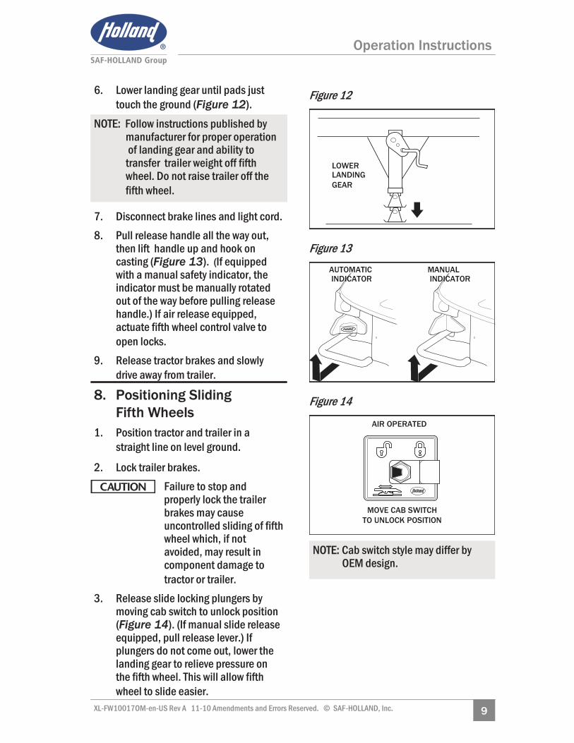
6. Lower landing gear until pads just touch the ground (Figure 12).
7. Disconnect brake lines and light cord. 8. Pull release handle all the way out,
then lift handle up and hook on casting (Figure 13). (If equipped with a manual safety indicator, the indicator must be manually rotated out of the way before pulling release handle.) If air release equipped, actuate fifth wheel control valve to open locks.
9. Release tractor brakes and slowly drive away from trailer.
8. Positioning Sliding Fifth Wheels
1. Position tractor and trailer in a straight line on level ground.
2. Lock trailer brakes. Failure to stop and properly lock the trailer
brakes may cause uncontrolled sliding of fifth wheel which, if not avoided, may result in component damage to tractor or trailer. 3. Release slide locking plungers by
moving cab switch to unlock position (Figure 14). (If manual slide release equipped, pull release lever.) If plungers do not come out, lower the landing gear to relieve pressure on the fifth wheel. This will allow fifth wheel to slide easier.
Figure 12
Figure 13
Figure 14
NOTE: Follow instructions published by manufacturer for proper operation of landing gear and ability to transfer trailer weight off fifth wheel. Do not raise trailer off the fifth wheel.
NOTE: Cab switch style may differ by OEM design.
LOWER LANDING GEAR
AIR OPERATED
MOVE CAB SWITCH TO UNLOCK POSITION
AUTOMATIC INDICATOR
MANUAL INDICATOR

10 XL-FW10017OM-en-US Rev A 1110 Amendments and Errors Reserved. © SAF-HOLLAND, Inc.
Maintenance Procedures
4. Slowly drive the tractor forward or backward to position fifth wheel and stop tractor at desired position.
5. Re-engage slide locking plungers by moving cab switch to the lock position (Figure 15). (If manual slide release equipped, trip release arm to allow plungers to retract.)
6. Retract landing gear legs if lowered.
7. Verify that slide locking plungers have been re-engaged by performing a pull test. Lock trailer brakes and pull for-ward with tractor to make sure fifth wheel does not slide (Figure 16).
Failure to properly engage plungers and slide base may
cause loss of vehicle control which, if not avoided, could result in death or serious injury. FIFTH WHEEL MAINTENANCE
Failure to properly maintain your fifth wheel could result
in tractor trailer separation which, if not avoided, may result in death or serious injury.
Figure 15
Figure 16
IMPORTANT: Do not operate the vehicle if the plungers are not fully engaged (locked).
IMPORTANT: All maintenance must be performed by a trained technician using proper tools and safe procedures. IMPORTANT: All maintenance must be performed while the tractor is uncoupled from the trailer.
AIR OPERATED
MOVE CAB SWITCH TO LOCK POSITION
LOCK TRAILER BRAKES AND PULL FORWARD WITH TRAILER
NOTE: Follow instructions published by landing gear manufacturer for proper operation of landing gear.

11 XL-FW10017OM-en-US Rev A 11-10 Amendments and Errors Reserved. © SAF-HOLLAND, Inc.
Maintenance Procedures
9. Top Plate Removal
Failure to prevent bracket pads or shoes from falling
out of the top plate could cause a potentially hazardous situation which, if not avoided, may result in minor or moderate injury. 1. Remove bracket pin retention nuts
and bolts from both sides of fifth wheel top plate (Figure 17).
2. Using a pry bar, pull bracket pins out of fifth wheel top plate (Figure 17).
3. Using a lifting device capable of lifting 500 lbs., remove the top plate from the mounting base. Place fifth wheel on a flat, clean working area.
Figure 17 NOTE: Removal of the fifth wheel top plate is not required for maintenance but may be required when performing repairs.
IMPORTANT: Fifth wheel assembly has replaceable bracket pads and shoes installed between the fifth wheel top plate and mounting base. Take care when removing fifth wheel top plate not to lose bracket pads or shoes.
BRACKET PIN
TOP PLATE
RETENTION NUT RETENTION BOLT
NOTE: Follow instructions published by lifting device manufacturer for proper operation of lifting device.

12 XL-FW10017OM-en-US Rev A 1110 Amendments and Errors Reserved. © SAF-HOLLAND, Inc.
Maintenance Procedures
10. Fifth Wheel Lubrication
Lubricate locking mechanism every 3 months or 30,000 miles.
Thoroughly clean the locking mechanism every 6 months or 60,000 miles.
10.A. Proper Lubrication Method 1. Remove old grease and debris from
all fifth wheel-to-trailer contact surfaces. Apply new water-resistant lithium-based grease to all fifth wheel-to-trailer contact surfaces (Figures 18 and 19).
2. Using water-resistant lithium-based grease, lubricate (Item 1) jaw where contact is made with kingpin. Also lubricate where lock contacts casting (Item 2) as shown (Figure 19).
3. Using a light oil, lubricate (Item 3) release handle pivot (Figure 19).
Figure 18
Figure 19
IMPORTANT: If your fifth wheel operates in snowy or icy winter conditions, lubrication should be performed every spring in addition to routine lubrication (as noted above), to ensure optimum operation.
GREASE THE TRAILER CONTACT SURFACE
IMPORTANT: Fifth wheel lubrication is necessary to get the maxi- mum service life from your SE or II SE fifth wheel. Perform the following procedures at the intervals shown.
1
3
2

13 XL-FW10017OM-en-US Rev A 11-10 Amendments and Errors Reserved. © SAF-HOLLAND, Inc.
Maintenance Procedures
10.B As-Needed Lubrication Maintain lubrication on fifth wheel-to-trailer contact surfaces. Use a water-resistant lithium-based grease. Clean grease grooves if a large amount of debris is present.
Clean and lubricate locking mechanism if operational difficulties arise during the service life of your fifth wheel (i.e. problems with cou-pling, uncoupling, or pulling the release handle).
11. Fifth Wheel Adjustment Fifth wheel adjustment should be checked at a minimum of every 60,000 miles or if excessive movement between kingpin and fifth wheel is noticed when driving the vehicle.
Failure to maintain proper fifth wheel adjustment
could result in loss of vehicle control which, if not avoided, could result in death or serious injury.
IMPORTANT: Excessive movement between the tractor and trailer can effect vehicle handling.
NOTE: To obtain proper fifth wheel adjustment SAF-HOLLAND recommends use of Holland lock tester Part No. 4000171, available from your local Holland distributor.

14 XL-FW10017OM-en-US Rev A 1110 Amendments and Errors Reserved. © SAF-HOLLAND, Inc.
Figure 20
Figure 21
AUTOMATIC INDICATOR
MANUAL INDICATOR
1. If fifth wheel is locked, pull release handle all the way out, then lift han-dle up and hook on casting. (If equipped with a manual safety indicator, the indicator must be manually rotated out of the way before pulling release handle.) If air release equipped, actuate fifth wheel control valve to open lock (Figure 20).
2. Ram lock tester into fifth wheel top plate to lock fifth wheel (Figure 21).
3. Push the lock tester forward so that it is tight against the fifth wheel’s front lock. Ensure the lock tester is pressed flat against the surface of the fifth wheel. Scribe a line on the sur-face of the fifth wheel face along front edge of lock tester (Figure 22).
4. Pull lock tester toward fifth wheel ramps. Ensure the lock tester is pressed flat against the surface of the fifth wheel. Scribe a second line on the surface of the fifth wheel face along front edge of lock tester (Figure 23).
Figure 22
Figure 23
FIFTH WHEEL FRONT LOCK
SCRIBE FIRST LINE
SCRIBE SECOND LINE
Maintenance Procedures
15 XL-FW10017OM-en-US Rev A 11-10 Amendments and Errors Reserved. © SAF-HOLLAND, Inc.
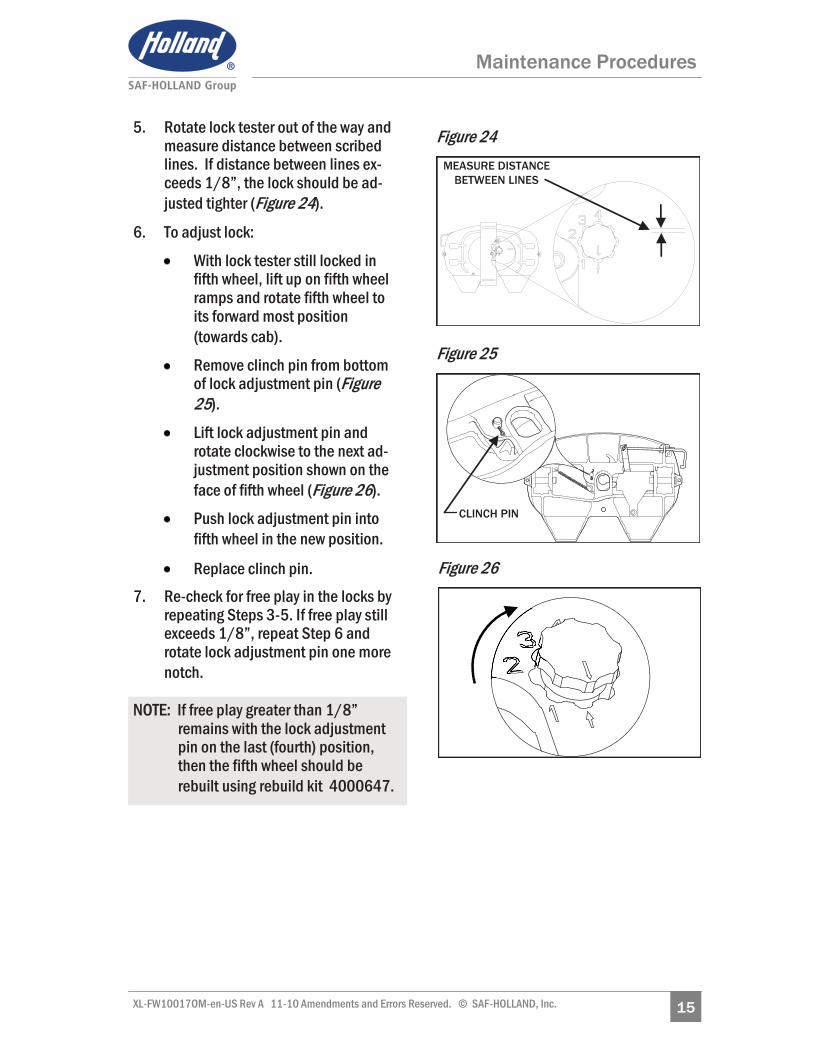
5. Rotate lock tester out of the way and measure distance between scribed lines. If distance between lines ex-ceeds 1/8”, the lock should be ad-justed tighter (Figure 24).
6. To adjust lock:
With lock tester still locked in fifth wheel, lift up on fifth wheel ramps and rotate fifth wheel to its forward most position (towards cab).
Remove clinch pin from bottom of lock adjustment pin (Figure 25).
Lift lock adjustment pin and rotate clockwise to the next ad-justment position shown on the face of fifth wheel (Figure 26).
Push lock adjustment pin into fifth wheel in the new position.
Replace clinch pin. 7. Re-check for free play in the locks by
repeating Steps 3-5. If free play still exceeds 1/8”, repeat Step 6 and rotate lock adjustment pin one more notch.
NOTE: If free play greater than 1/8” remains with the lock adjustment pin on the last (fourth) position, then the fifth wheel should be rebuilt using rebuild kit 4000647.
Maintenance Procedures
Figure 24
Figure 25
MEASURE DISTANCE BETWEEN LINES
CLINCH PIN
Figure 26

16 XL-FW10017OM-en-US Rev A 1110 Amendments and Errors Reserved. © SAF-HOLLAND, Inc.
8. Verify the proper adjustment by lock-ing and unlocking fifth wheel several time with lock tester. Verify that there is at least 1/16” of forward and backward play in the lock by sliding a 1/16” drill bit between the front edge of the kingpin on the lock tester and the front lock (radius) of the fifth wheel (Figure 27).
If there is not 1/16” minimum free-play in the lock, the fifth wheel lock adjustment pin must be rotated coun-terclockwise to the next lower posi-tion. Reverify that 1/16” minimum play exists using 1/16” drill bit as described above. Check that the fifth wheel is properly locked.
9. Rotate lock adjustment tool from side-to-side to ensure that the lock is not over tightened. The lock should not grip the kingpin and the lock tester should rotate freely.
12. Bracket Pad and Shoe
Inspection Replace bracket pads and shoes if:
The free vertical movement of top plate on the bracket exceeds 3/8” (Figure 28).
The bracket pads or shoes are severely chipped, cracked or gouged.
Figure 28
PUSH DOWN
3/8” MAX. (MEASURED AT EAR)
Maintenance Procedures
Figure 27
NOTE: A minimum of 1/16” free play is critical to proper operation of the fifth wheel.

17 XL-FW10017OM-en-US Rev A 11-10 Amendments and Errors Reserved. © SAF-HOLLAND, Inc.
Figure 29
FIFTH WHEEL SURFACE
FORWARD SIDE RAMP
SIDE
BRACKET PAD
BRACKET SHOE
Figure 30
Figure 31
13. Top Plate Installation 1. If bracket pads are dislodged from
fifth wheel casting, reinstall by pressing the bracket pads down into bracket pockets. If bracket shoes are dislodged from fifth wheel casting, slide bracket shoe into bracket pocket by inserting one edge of the shoe into the forward (tractor ) side of the bracket pocket and fully rotating (sliding) it into bracket pocket (Figures 29—31).
2. Using a lifting device capable of lifting 500 lbs., install the fifth wheel top plate onto its mounting base.
3. Install bracket pins through fifth wheel casting and mounting base and secure by installing the bracket pin retention bolts and nuts (Figure 32). Torque retention bolts not to exceed 60 ft-lbs.
Figure 32
TOP PLATE
RETENTION BOLT
RETENTION NUT
BRACKET PIN
Maintenance Procedures
NOTE: Follow instructions published by lifting device manufacturer for proper operation of lifting device.
18 XL-FW10017OM-en-US Rev A 1110 Amendments and Errors Reserved. © SAF-HOLLAND, Inc.
Troubleshooting
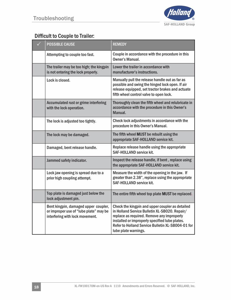
Difficult to Couple to Trailer: ��POSSIBLE CAUSE REMEDY
Attempting to couple too fast. Couple in accordance with the procedure in this Owner’s Manual.
The trailer may be too high; the kingpin is not entering the lock properly.
Lower the trailer in accordance with manufacturer’s instructions.
Lock is closed. Manually pull the release handle out as far as possible and swing the hinged lock open. If air release equipped, set tractor brakes and actuate fifth wheel control valve to open lock.
Accumulated rust or grime interfering with the lock operation.
Thoroughly clean the fifth wheel and relubricate in accordance with the procedure in this Owner’s Manual.
The lock is adjusted too tightly. Check lock adjustments in accordance with the procedure in this Owner’s Manual.
The lock may be damaged. The fifth wheel MMUST be rebuilt using the appropriate SAF-HOLLAND service kit.
Damaged, bent release handle. Replace release handle using the appropriate SAF-HOLLAND service kit.
Jammed safety indicator. Inspect the release handle, if bent , replace using the appropriate SAF-HOLLAND service kit.
Lock jaw opening is spread due to a prior high coupling attempt.
Measure the width of the opening in the jaw. If greater than 2.38”, replace using the appropriate SAF-HOLLAND service kit.
Top plate is damaged just below the lock adjustment pin.
The entire fifth wheel top plate MMUST be replaced.
Bent kingpin, damaged upper coupler, or improper use of “lube plate” may be interfering with lock movement.
Check the kingpin and upper coupler as detailed in Holland Service Bulletin XL-SB020. Repair/replace as required. Remove any improperly installed or improperly specified lube plates. Refer to Holland Service Bulletin XL-SB004-01 for lube plate warnings.

19 XL-FW10017OM-en-US Rev A 11-10 Amendments and Errors Reserved. © SAF-HOLLAND, Inc.
Troubleshooting
Difficult to Uncouple from Trailer: ��POSSIBLE CAUSE REMEDY
The tractor may be putting pressure against the locks.
Lock the trailer brakes and back the tractor tightly against the kingpin to relieve the pressure on the fifth wheel lock, set the brakes, then pull the release handle.
Tractor too low. Raise tractor suspension to proper ride height.
The primary release handle is not pulled out completely and hooked on the notch in the casting.
Pull the release handle all the way out, then lift handle up and hook on casting.
Accumulated rust or grime interfering with the lock operation.
Thoroughly clean the fifth wheel and relubricate in accordance with the procedure in this Owner’s Manual.
The lock is adjusted too tightly. Check lock adjustments in accordance with the procedure in this Owner’s Manual.
The release handle will not stay out or must be held out when unlocking.
The fifth wheel MMUST be rebuilt using the appropriate SAF-HOLLAND service kit.
Missing or damaged release system parts.
The fifth wheel MMUST be rebuilt using the appropriate SAF-HOLLAND service kit.
Casting bent/damaged at throat area, restricting movement.
The entire fifth wheel top plate MMUST be replaced.
Bent cover plate interfering with lock movement.
Inspect the cover plate for flatness and replace, if necessary.
Bent kingpin, damaged upper coupler, or improper use of “lube plate” may be interfering with lock movement.
Check the kingpin and upper coupler as detailed in Holland Service Bulletin XL-SB020. Repair/replace as required. Remove any improperly installed or improperly specified lube plates. Refer to Holland Service Bulletin XL-SB004-01 for lube plate warnings.
NOTE: After the fifth wheel is unlocked and disengages from the kingpin, it is normal for the release handle to come off the unlock notch of the casting and move into a “ready-to-couple” position.
20 XL-FW10017OM-en-US Rev A 1110 Amendments and Errors Reserved. © SAF-HOLLAND, Inc.
Troubleshooting
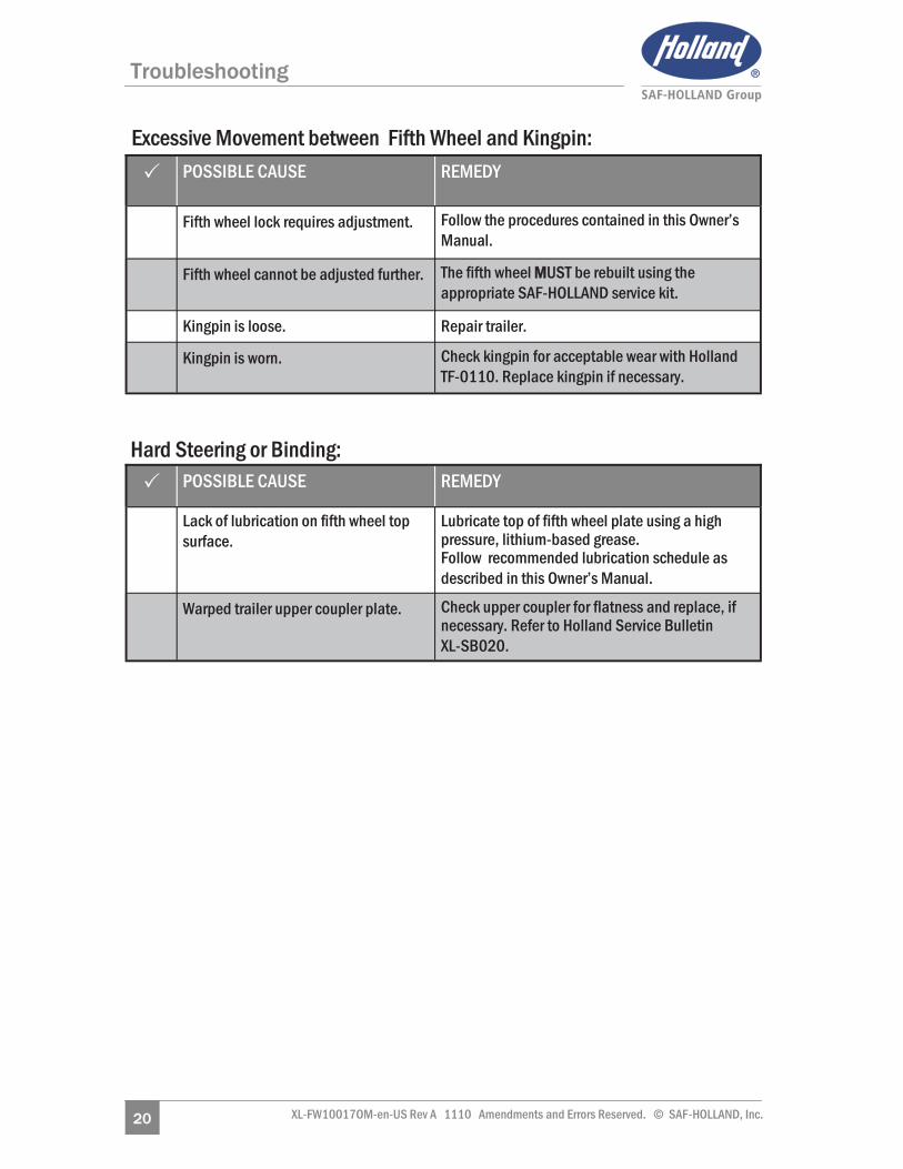
��POSSIBLE CAUSE REMEDY
Fifth wheel lock requires adjustment. Follow the procedures contained in this Owner’s Manual.
Fifth wheel cannot be adjusted further. The fifth wheel MMUST be rebuilt using the appropriate SAF-HOLLAND service kit.
Kingpin is loose. Repair trailer.
Kingpin is worn. Check kingpin for acceptable wear with Holland TF-0110. Replace kingpin if necessary.
Excessive Movement between Fifth Wheel and Kingpin:
Hard Steering or Binding: ��POSSIBLE CAUSE REMEDY
Lack of lubrication on fifth wheel top surface.
Lubricate top of fifth wheel plate using a high pressure, lithium-based grease. Follow recommended lubrication schedule as described in this Owner’s Manual.
Warped trailer upper coupler plate. Check upper coupler for flatness and replace, if necessary. Refer to Holland Service Bulletin XL-SB020.
21 XL-FW10017OM-en-US Rev A 11-10 Amendments and Errors Reserved. © SAF-HOLLAND, Inc.
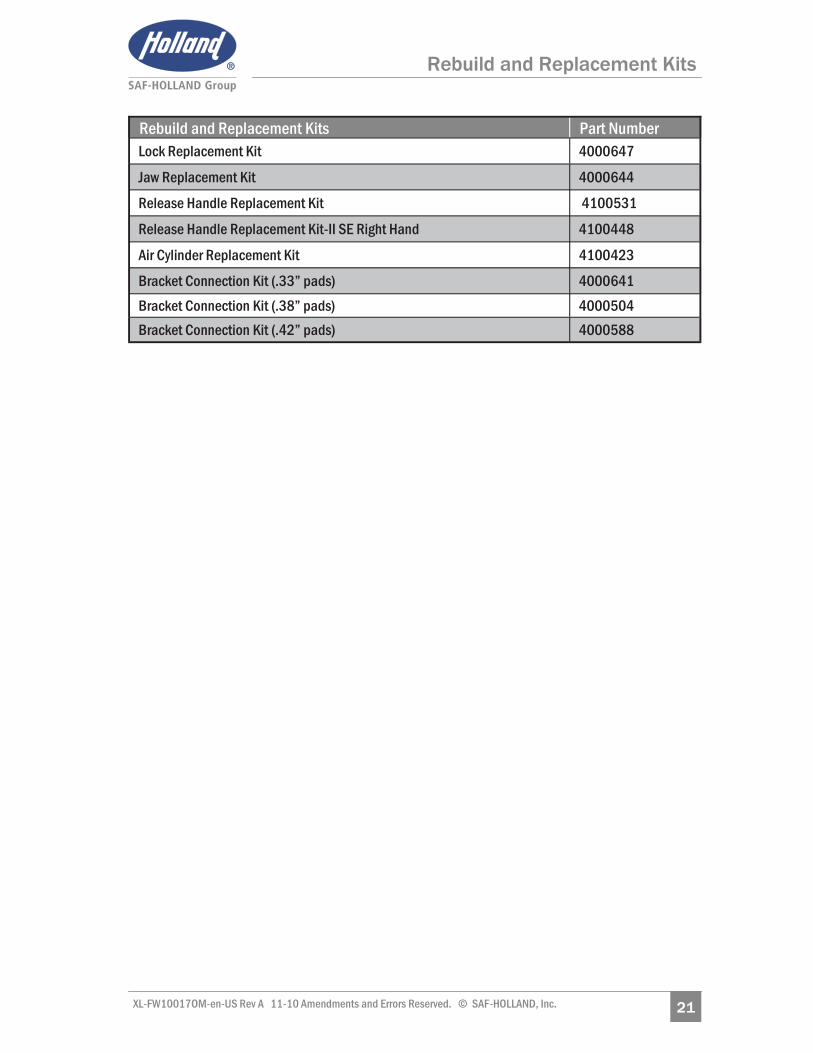
Rebuild and Replacement Kits
Rebuild and Replacement Kits Part Number Lock Replacement Kit 4000647
Jaw Replacement Kit 4000644
Release Handle Replacement Kit 4100531
Release Handle Replacement Kit-II SE Right Hand 4100448
Air Cylinder Replacement Kit 4100423
Bracket Connection Kit (.33” pads) 4000641 Bracket Connection Kit (.38” pads) 4000504 Bracket Connection Kit (.42” pads) 4000588

22 XL-FW10017OM-en-US Rev A 1110 Amendments and Errors Reserved. © SAF-HOLLAND, Inc.
Notes

23 XL-FW10017OM-en-US Rev A 11-10 Amendments and Errors Reserved. © SAF-HOLLAND, Inc.

XL-F
W10
017O
M-e
n-US
Rev
A 2
010-
11-0
1 A
men
dmen
ts a
nd Er
rors
Res
erve
d. ©
SAF
-HOL
LAND
, Inc
.