OWNER'S MANUAL & SERVICE GUIDE - Jacobsen Turf...
68
OWNER'S MANUAL & SERVICE GUIDE R ST 480 Starting Model Year 2003
Transcript of OWNER'S MANUAL & SERVICE GUIDE - Jacobsen Turf...

OWNER'S MANUAL & SERVICE GUIDE
R
ST 480
Starting Model Year 2003

MANUAL INFORMATIONFor any questions on material contained in this manual, contact a representativefor clarification.
Read and understand all labels located on the vehicle. Always replace any dam-aged or missing labels.
On steep hills it is possible for vehicles to coast at greater than normal speedsencountered on a flat surface. To prevent loss of vehicle control and possibleserious injury, speeds should be limited to no more than the maximum speed onlevel ground. (See vehicle specification.) Limit speed by applying the servicebrake.
Catastrophic damage to the drive train components due to excessive speedmay result from driving the vehicle above specified speed. Damage caused byexcessive speed may cause a loss of vehicle control, is costly, is consideredabuse and will not be covered under warranty.
Be sure that this manual remains as part of the permanent service recordshould the vehicle be re-sold.
Throughout this guide, NOTE, CAUTION and WARNING will be used.
A NOTE indicates a condition that should beobserved.
A CAUTION indicates a condition thatmay result in damage to the vehicle.
A WARNING indicates ahazardous condition whichcould result in severe injury
or death.
Please observe these notes, cautions, and warnings; be aware that servicing avehicle requires mechanical skill and a regard for conditions that could be haz-ardous. Improper service or repair may damage the vehicle or render it unsafe.
Engine exhaust from thisproduct contains chemicalsknown, in certain quanti-
ties, to cause cancer, birth defects, or otherreproductive harm.
The exhaust emissions of this vehicles’ enginecomplies with regulations set forth by the Environ-
mental Protection Agency (EPA) of the United States of America(USA) at time of manufacture. Significant fines could result frommodifications or tampering with the engine, fuel, ignition or airintake systems.
Battery posts, terminalsand related accessoriescontain lead and lead com-
pounds. Wash hands after handling.This spark ignition system meets all requirementsof the Canadian Interference-Causing Equipment
Regulations.
! !
! !
! !
Ce système d'allumage par étincelle de véhicule respectetoutes les exigences du Règlement sur le matériel brouilleurdu Canada.

i
OWNER’S MANUAL & SERVICE GUIDE
ST 480
Textron Golf, Turf & Specialty Products reserves the right to make design changes without obligation to make these changes on units previously sold and the information contained in this manual is subject to change without notice.Textron Golf, Turf & Specialty Products is not liable for errors in this manual or for incidental or consequential damage that result from the use of material in this manual.
CUSTOMER SERVICE DEPARTMENT IN USA PHONE: 1-800-241-5855 FAX: 1-800-448-8124OUTSIDE USA PHONE: 010-1-706-798-4311 FAX: 010-1-706-771-4609
TEXTRON GOLF, TURF & SPECIALTY PRODUCTS, P.O. BOX 388 AUGUSTA, GEORGIA 30903-0388 USA
ii
NOTES
To obtain a copy of the limited warranty applicable to the vehicle, call or write a local Distributor, authorized Branch orthe Warranty Department with vehicle serial number and manufacture date code.
The use of non Original Equipment Manufacturer (OEM) approved parts may void the warranty.
Tampering with or adjusting the governor to permit vehicle to operate at above factory specifications will voidthe vehicle warranty.
When servicing engines, all adjustments and replacement components must be per original vehicle specifications in order to maintain the United States of America Federal and State emission certification applicable at the time of manufacture.
BATTERY PROLONGED STORAGE
All batteries will self discharge over time. The rate of self discharge varies depending on the ambient temperatureand the age and condition of the battery.
A fully charged battery will not freeze in winter temperatures unless the temperature falls below -75° F (-60° C).

TABLE OF CONTENTS
1-1
TITLE PAGE TITLE PAGE
MANUAL INFORMATION.......................... Inside Front Cover
NOTES ...................................................................................... i
SAFETY INFORMATION ......................................................2-1
OPERATION AND SERVICE INFORMATION .....................3-1BEFORE INITIAL USE ................................................................................3-1
Fig. 1 Initial Service Chart ..........................................................3-2
TERRAIN .....................................................................................................3-2
VEHICLE CAPACITY ..................................................................................3-2
MODIFICATIONS TO VEHICLE ..................................................................3-3
COMMON SENSE OPERATION .................................................................3-3
POWER CONSUMPTION ...........................................................................3-3
ENVIRONMENTAL CONCERNS ................................................................3-4
OPTIONAL WINCH .....................................................................................3-4OPERATION OF THE WINCH ...............................................................3-4
Fig. 2 Winch Mounted to Vehicle ................................................3-4Fig. 3 Winch Remote Control .....................................................3-5Fig. 4 Winch Clutch Knob ...........................................................3-5
WINCH APPLICATIONS ........................................................................3-5Fig. 5 Never Operate Winch with Less Than
Five Turns Around Drum ..................................................3-6Fig. 6 Do Not Hook Cable to Itself ..............................................3-7Fig. 7 Use a Nylon Sling and Install a Damper when Winching .3-7Fig. 8 Do Not Pull at Angle .........................................................3-8
CONTROLS AND INDICATORS .................................................................3-8KEY/LIGHT SWITCH .............................................................................3-8
Fig. 9 Key/Light Switch, Low Oil Pressure Light and Fuel Gauge 3-8DIRECTION SELECTOR .......................................................................3-9
Fig. 10 Console Controls ............................................................3-9CHOKE ...................................................................................................3-9FUEL GAUGE ........................................................................................3-9LOW OIL PRESSURE INDICATOR LIGHT ...........................................3-9ACCELERATOR PEDAL ........................................................................3-9
Fig. 11 Accelerator, Brake and Horn ........................................3-10
SERVICE BRAKE PEDAL ...................................................................3-10PARK BRAKE ......................................................................................3-10HORN ...................................................................................................3-10DIFFERENTIAL LOCK .........................................................................3-10
LOAD BED ................................................................................................3-11ELECTRIC LIFT BED OPERATION ....................................................3-11
Fig. 12 Electric Lift Switch ........................................................3-11
OPERATING THE VEHICLE .....................................................................3-12RUN-IN .................................................................................................3-13
Fig. 13 Check Oil Level on Dipstick .........................................3-13COLD STARTING ................................................................................3-13STARTING AND DRIVING ..................................................................3-14STARTING THE VEHICLE ON A HILL ................................................3-14COASTING ..........................................................................................3-14FUEL ....................................................................................................3-15
Fig. 14 Fueling .........................................................................3-15BATTERY .............................................................................................3-15LABELS AND PICTOGRAMS ..............................................................3-16SUN TOP AND WINDSHIELD .............................................................3-1612 VOLT POWER OUTLET .................................................................3-16
Fig. 15 12 Volt Power Outlet ....................................................3-16TOWING A TRAILER ...........................................................................3-16
VEHICLE CLEANING AND CARE ...........................................................3-17VEHICLE CLEANING ..........................................................................3-17VEHICLE CARE PRODUCTS ..............................................................3-17
REPAIR .....................................................................................................3-18LIFTING THE VEHICLE .......................................................................3-18
Fig. 16 Lifting the Vehicle .........................................................3-19WHEELS AND TIRES ..........................................................................3-19
Tire Repair .....................................................................................3-19Wheel Installation ..........................................................................3-20
Fig. 17 Wheel Installation .........................................................3-21LIGHT BULB REPLACEMENT ............................................................3-21
Fig. 18 Headlight and Turn Signal Bulb Replacement .............3-21Fig. 19 Tail and Brake Light Bulb Replacement .......................3-21
FUSE REPLACEMENT ........................................................................3-21VEHICLE WITH A DISCHARGED BATTERY ......................................3-22
TRANSPORTING VEHICLE .....................................................................3-22

1-2
TABLE OF CONTENTSTITLE PAGE TITLE PAGE
TOWING .............................................................................................. 3-22NEUTRAL LOCK ................................................................................. 3-22
Fig. 20 Neutral Lock ................................................................. 3-23HAULING ............................................................................................. 3-22
SERVICE AND MAINTENANCE .............................................................. 3-23SERIAL NUMBER PLATE LOCATION ................................................ 3-25
Fig. 21 Serial Number Plate Location ...................................... 3-25PERIODIC SERVICE SCHEDULE ..................................................... 3-26
Fig. 22 Periodic Service Schedule ........................................... 3-26TIRE INSPECTION .............................................................................. 3-28SEAT PROP ........................................................................................ 3-28
Fig. 23 Seat Prop ..................................................................... 3-29REPLACING THE FUEL FILTER ........................................................ 3-29CHECKING THE OIL LEVEL ............................................................... 3-29
Fig. 24 Oil Fill Cap, Dipstick and Fuel Filter ............................. 3-30Fig. 25 Clean Entire Dipstick ................................................... 3-30Fig. 26 Check Oil Level on Dipstick ......................................... 3-30
CHANGING THE OIL ........................................................................... 3-30Fig. 27 Oil Viscosity Chart ....................................................... 3-31
CHANGING THE OIL FILTER ............................................................. 3-32Fig. 28 Oil Drain and Filter ....................................................... 3-32
LUBRICATION ..................................................................................... 3-32Fig. 29 Lubrication Points ........................................................ 3-32
AIR CLEANER INSPECTION AND REPLACEMENT ......................... 3-33Pre-Cleaner Service ...................................................................... 3-33Cartridge Service ........................................................................... 3-33
Fig. 30 Air Cleaner ................................................................... 3-33REAR AXLE ......................................................................................... 3-34
Checking the Lubricant Level ........................................................ 3-34Fig. 31 Add, Check and Drain Rear Axle Lubricant ................. 3-34
STARTER/GENERATOR BELT TENSION ......................................... 3-34Fig. 32 Check Belt Tension with Gauge .................................. 3-35Fig. 33 Check Belt Tension with Finger ................................... 3-35
Adjusting the Belt .......................................................................... 3-35Fig. 34 Adjust Belt Tension ...................................................... 3-35
BATTERY CLEANING ......................................................................... 3-36Fig. 35 Preparing Acid Neutralizing Solution ........................... 3-36
AIR INTAKE AND COOLING FINS ...................................................... 3-36Fig. 36 Cleaning Air Intake and Cooling Fins .......................... 3-37
SPARK PLUGS ................................................................................... 3-37BRAKES .............................................................................................. 3-37
Daily Brake Test ............................................................................ 3-37PROLONGED STORAGE ................................................................... 3-38HARDWARE ........................................................................................ 3-38
Fig. 37 Torque Specifications and Bolt Grades ....................... 3-39CAPACITIES AND REPLACEMENT PARTS ..................................... 3-40
Fig. 38 Capacities and Replacement Parts ............................. 3-40
GENERAL SPECIFICATIONS..............................................4-1ST 480 .................................................................................................... 4-1
Fig. 1 Vehicle Dimensions .......................................................... 4-2Fig. 2 Vehicle Incline Specifications ........................................... 4-3Fig. 3 Vehicle Turning Clearance Diameter and
Intersecting Aisle Clearance............................................. 4-4
LIMITED WARRANTY ..........................................................5-1
DECLARATION OF CONFORMITY .....................................6-1
LABELS AND PICTOGRAMS............................. APPENDIX A

SAFETY INFORMATIONRead all of manual to become thoroughly familiar with this vehicle. Pay particular attention to all Notes, Cautions and Warnings
2-1
The Owner’s Manual and Service Guide has been designed to assist in main-taining the vehicle in accordance with procedures developed by the manufac-turer. Adherence to these procedures and trouble-shooting tips will ensure thebest possible service from the product. To reduce the chance of personal injuryand/or property damage, the following instructions must be carefully observed:
GENERALMany vehicles are used for a variety of tasks beyond the original intended use ofthe vehicle; therefore, it is impossible to anticipate and warn against every possi-ble combination of circumstances that may occur.
Good common sense and prudent driving practices do more to prevent acci-dents and injury than all of the warnings and instructions combined. The manu-facturer strongly suggests that the owner-operator read this entire Owner’sManual and Service Guide paying particular attention to the CAUTIONS andWARNINGS contained therein. It is further recommended that other operatorsbe encouraged to do the same.
If you have any questions, contact your closest representative or write to theaddress on the back cover of this publication, Attention: Product Service Depart-ment.
• Textron Golf, Turf & Specialty Products is not liable for errors in this manualor for incidental or consequential damages that result from the use of thematerial in this manual.
• Textron Golf, Turf & Specialty Products reserves the right to make designchanges without obligation to make these changes on units previouslysold and the information contained in this manual is subject to changewithout notice.
• This vehicle conforms to the current applicable standard for safety andperformance requirements.
• These vehicles are designed and manufactured for off-road use. They donot conform to Federal Motor Vehicle Safety Standards of the United
States of America (USA) and are not equipped for operation on publicstreets. Some communities may permit these vehicles to be operated ontheir streets on a limited basis and in accordance with local ordinances.
• Vehicle capacity is limited to a maximum of two persons.
• Never modify the vehicle in any way that will alter the weight distribution ofthe vehicle, decrease its stability or increase the speed beyond the factoryspecification. Such modifications can cause serious personal injury ordeath. Modifications that increase the speed and or weight of the vehiclewill extend the stopping distance and may reduce the stability of the vehi-cle. Do not make any such modifications or changes. The manufacturerprohibits and disclaims responsibility for any such modifications or anyother alteration which would adversely affect the safety of the vehicle.
GENERAL OPERATIONThe following information is very important in the operation of the vehicle. Theoperator should read, understand and always observe the following:
• Use the vehicle in a responsible manner and maintain the vehicle in safeoperating condition.
• Read, understand and observe all warnings and operation instructionlabels affixed to the vehicle.
• Follow all safety rules established in the area where the vehicle is beingoperated.
• Reduce speed to compensate for unsuitable terrain or conditions.
• Apply service brake to control speed on steep grades.
• Reduce speed in wet areas.
• Use extreme caution and reduced speed when approaching sharp or blindturns.
• Use extreme caution and reduced speed when driving over loose terrain.
• Use extreme caution and reduced speed in areas where pedestrians arepresent.

SAFETY INFORMATIONRead all of manual to become thoroughly familiar with this vehicle. Pay particular attention to all Notes, Cautions and Warnings
2-2
MAINTENANCEThe following information is very important in the maintenance of the vehicle.The person performing maintenance procedures should read, understand andalways observe the following:
• Maintain your vehicle in accordance with the manufacturer’s periodic ser-vice schedule.
• Ensure that mechanics performing repairs are trained and qualified to doso.
• Follow the manufacturer’s directions if you perform maintenance on yourown vehicle. Be sure to disable the vehicle before performing any mainte-nance. Disabling includes removing the key from the key switch andremoval of a battery wire.
• Insulate any tools used within the battery area in order to prevent sparks orbattery explosion caused by shorting the battery terminals or associatedwiring. Remove the battery or cover exposed terminals with an insulatingmaterial.
• Check the polarity of each battery terminal and be sure to rewire the bat-tery correctly.
• Use specified replacement parts. Never use replacement parts of lesserquality.
• Use only tools recommended by the manufacturer.
• Determine that tools and procedures not specifically recommended by themanufacturer will not compromise the safety of personnel nor jeopardizethe safe operation of the vehicle.
• Support the vehicle using wheel chocks and jack stands. Never get undera vehicle that is supported by a jack. Lift the vehicle in accordance with themanufacturer’s instructions.
• Never attempt to perform vehicle maintenance in an area where exposedflame is present or persons are smoking.
• Be aware that a vehicle that is not performing as designed is a potentialhazard and must not be operated until inspected and repaired.
• The manufacturer cannot anticipate all dangerous situations. Peopleattempting to maintain or repair the vehicle must have the skill and experi-ence to recognize and protect themselves from potential dangerous situa-tions. These situations could result in severe personal injury or death anddamage to the vehicle. Use extreme caution and if unsure as to the poten-tial for injury refer the repair or maintenance to a qualified mechanic.
• Test drive the vehicle after any repairs are made or maintenance proce-dures performed to assure the vehicle is safe to return to service. All testsmust be conducted in a safe area that is free of both vehicular and pedes-trian traffic.
• Replace damaged or missing warning, caution or information labels.
• Keep complete records of the maintenance history of the vehicle.
VENTILATION• Always store gasoline vehicles in a well ventilated area to prevent gasoline
fumes from accumulating.
• Never fuel a vehicle in an area that is subject to flame or spark. Pay partic-ular attention to natural gas or propane water heaters and furnaces.
• Never work around or operate a vehicle in an environment that does notventilate exhaust gases from the area. Carbon monoxide is a dangerousgas that can cause unconsciousness and is potentially lethal.

OPERATION AND SERVICE INFORMATION
3-1
Read all of manual to become thoroughly familiar with this vehicle. Pay particular attention to all Notes, Cautions and Warnings \
Thank you for purchasing a light duty utility vehicle. Before driving thevehicle, we ask you to spend some time reading this Owner’s Manualand Service Guide and the Operating and Maintenance Instructionsmanual provided by the engine manufacturer. These manuals containthe information that will assist you in the safe operation of the vehicle.They will also assist you in maintaining this highly reliable vehicle.Some illustrations may show items that are optional for your vehicle.
This vehicle has been designed and manufactured as a ‘World Vehi-cle’. Some countries have individual requirements to comply with theirspecifications; therefore, some sections may not apply in your country.
Most of the service procedures in this guide can be accomplishedusing common automotive hand tools. Contact your service represen-tative on servicing the vehicle in accordance with the Periodic ServiceSchedule.
Service Parts Manuals, Technician’s Repair and Service Manuals andengine Repair Manuals are available from a local Distributor, an autho-rized Branch or the Service Parts Department. When ordering parts orrequesting information for your vehicle, provide vehicle model, serialnumber and manufacture date code.
BEFORE INITIAL USERecord the four digit key number and store in a safeplace. Individual keys can only be replaced if the
key number is known. Without a key number, the entire ignitionswitch will have to be replaced if keys are lost.
Read, understand and follow the safety label on the instrument panel(Ref Appendix A). Be sure you understand how to operate the vehicle,its equipment and how to use it safely. Maintaining good performancedepends to a large extent on the operator.
Improper use of this vehiclecould result in severe injuryor death. The ST Series vehi-
cle is a light duty utility vehicle. It is NOT an all ter-rain vehicle (ATV).This vehicle is not a toy and using it while engag-ing in horseplay is dangerous.Plan carefully before using the vehicle to go sig-nificant distances over questionable terrain.Remember that a one hour drive may take manyhours to walk out should you run out of fuel or bestranded by becoming stuck on unsuitable terrain.Hydrogen gas is generated as a natural part of thelead acid battery charging process. A 4% concen-
! !

OPERATION AND SERVICE INFORMATION
3-2
Read all of manual to become thoroughly familiar with this vehicle. Pay particular attention to all Notes, Cautions and Warnings
tration of hydrogen gas is explosive and couldcause severe injury or death. Charging must takeplace in an area that is adequately ventilated (min-imum of 5 air exchanges per hour).To reduce the chance of battery explosion thatcould result in severe injury or death, neversmoke around or charge batteries in an area thathas open flame or electrical equipment that couldcause an electrical arc.
Before a new vehicle is put into operation, the items shown in the INI-TIAL SERVICE CHART must be performed (Ref Fig. 1 on page 3-2).
Vehicle battery must be fully charged before initial use.
Check for correct tire inflation. See GENERAL SPECIFICATIONS.
Check for oil or fuel leaks that could have developed in shipment fromthe factory.
Check for a firm brake pedal. Determine and record braking distancerequired to stop vehicle for future brake performance tests.
Record and keep key number.
Remove the protective clear plastic, that protect the seat bottom andback rest during shipping, before placing the vehicle in service.
TERRAINThe vehicle is designed for use on improved roads (but not on publichighways). The vehicle may also be used on established trails or openterrain that is free from stumps, large rocks or holes.
The vehicle should not be used to cross water.
VEHICLE CAPACITYDue to the variety of ways thevehicle may be used, it isimportant that the operator
consider any potential hazards before use to pre-vent serious injury or death.
The vehicle may be used to transport a maximum of two peoplewithin the operator/passenger compartment and cargo in the loadbed. Never carry passengers in the load bed. The total payload is800 lbs. (363 kg). The weight of the driver and passenger plus anyoptions or accessories must be deducted from the total payload ratingto determine the load bed capacity. Remember that towing a trailer willreduce the payload of the vehicle itself.
Fig. 1 Initial Service Chart
ITEM SERVICE OPERATION
Battery Charge battery
Seats Remove protective plastic covering
Brakes Check operation and adjust if necessary
Check hydraulic brake fluid level
Tires Check air pressure (see SPECIFICATIONS)
Fuel Fill tank with correct fuel
Engine Check oil level (Initial change after 5 - 8 hours)
Keys Record key number and store in safe location
! !

OPERATION AND SERVICE INFORMATION
3-3
Read all of manual to become thoroughly familiar with this vehicle. Pay particular attention to all Notes, Cautions and Warnings
Remember that volume of your load can be misleading. Loading thevehicle to its rated capacity with dry sand, fertilizer, sod, etc. can behandled with complete safety. The same load when wet will grosslyoverload the vehicle and increase the potential for roll over and dam-age to the vehicle.
MODIFICATIONS TO VEHICLEChanges to the weight distri-bution or the center of gravitymay make it unstable or prone
to roll over which could result in injury or death tothe operator or passenger.
Do not modify the vehicle in any manner that will change the weightdistribution of the vehicle. Changes to the weight distribution or the cen-ter of gravity may make it unstable or prone to roll over which couldresult in injury or death to the operator or passenger.
COMMON SENSE OPERATIONThis vehicle is not a toy. If not operated properly and responsibly, itcan cause severe injury or death to the operator, passenger orbystanders. All operators should possess a valid driver’s license. Chil-dren should not be permitted to operate the vehicle. Children may nothave the skill, judgement or strength to operate this or similar vehicles.
Alcohol, drugs and many over the counter medications reduce the abil-ity of the driver to operate the vehicle safely. Always review side effectsof any medication with a doctor or pharmacist before operating vehicle.
Protective clothing and an approved motorcycle helmet are recom-mended for operator and passenger at all times.
When driving at full speed on a dirt road, loose surfaces or wet grass,vehicle stopping distance will increase. If the vehicle is fully loaded, itwill take longer to stop than with no load. When operating vehicle in wetweather conditions, remember that the brakes may need to be lightlyapplied in order to provide enough friction to dry the brake unit. If wet,the brakes will lose much of their effect.
Slow down when in unfamiliar terrain. Slow down when cresting a hill inan area that you are unfamiliar with.
Some hills are too steep to climb. If you attempt to climb a hill that is toosteep or if you are unable to achieve adequate traction, do not attemptto turn around on the hill. Slowly back straight down the hill usingthe service brake to control speed.
POWER CONSUMPTIONThe vehicle uses a combination starter/generator to both start theengine and charge the battery. The engine will not idle; therefore, thebattery cannot be charged while the vehicle is stopped. Do not operateaccessory items (such as accessory lights, radios, winch, etc.) exces-sively while the vehicle is stopped.
Overuse of accessories may drainthe battery and leave insufficient
reserve to start the vehicle.
The generator is only capable of supplying 35 amps; therefore, opera-tion of all accessories could result in the discharge of the battery eventhough the engine is running and the generator operating. Dischargingthe battery is known as deep cycling. The battery is not a deep cycle
! !

OPERATION AND SERVICE INFORMATION
3-4
Read all of manual to become thoroughly familiar with this vehicle. Pay particular attention to all Notes, Cautions and Warnings
model, but is a starting battery. Multiple deep cycling of the battery willresult in the premature failure of the battery.
Vehicle battery must be fully charged before initial use.
Hydrogen gas is generated asa natural part of the lead acidbattery charging process. A
4% concentration of hydrogen gas is explosiveand could cause severe injury or death. Chargingmust take place in an area that is adequately ven-tilated (minimum of 5 air exchanges per hour).To reduce the chance of battery explosion thatcould result in severe injury or death, neversmoke around or charge batteries in an area thathas open flame or electrical equipment that couldcause an electrical arc.
ENVIRONMENTAL CONCERNSAs a responsible user, practice respect for all wildlife and their habitat.Respect private property and comply with all local laws and regulationsgoverning the use of light duty utility vehicles. Do not tamper with theexhaust system or governor. The exhaust system has been tuned tothe engine for maximum performance. Removal or modification of theexhaust is annoying to other people and will not improve the perfor-mance of the vehicle.
To prevent severe injury ordeath while driving, be awareof the following:
Environmental hazards such as steep slopes,overhanging limbs, etc.
Danger of fire when vehicle is operated over drycombustible organic material.
When driving, be aware of environmental hazards such as steepslopes, overhanging limbs, etc. Be aware of the danger of fire when thevehicle is operated over dry combustible organic material.
OPTIONAL WINCHThis vehicle may be equipped with an optional winch. Read, under-stand and follow all of the following information on the operation anduse of the winch before attempting to operate it.
OPERATION OF THE WINCHThe winch can be mounted at the front or rear of the vehicle andmoved to accommodate different situations. At the front, it is mountedunder the center of the front cowl to a bracket attached to the front axleas shown (Ref Fig. 2 on page 3-5). At the rear, the winch is mountedupside down in the hitch receiver.
If mounting winch at rear of vehicle, the winch mustbe mounted upside down.
Before moving the winch, unplug the winch connector from the wireharness. To move the winch from one end of the vehicle to the other,remove the spring pin, pull out the clevis pin and remove the winchmount tube from the receiver. Move to opposite end of vehicle andinstall by inserting clevis pin and securing with spring pin. Plug thewinch connector into wire harness.
! !
! !

OPERATION AND SERVICE INFORMATION
3-5
Read all of manual to become thoroughly familiar with this vehicle. Pay particular attention to all Notes, Cautions and Warnings
The winch remote control plugs into the receptacle on the driver side ofthe seat support (Ref Fig. 3 on page 3-5).
To unwind the cable, locate the clutch knob on the winch. Pull out knoband rotate 90° to lock out. Using handsaver bar, pull cable from winch
drum. Leave at least five turns of cable on drum. Re-engage drum byturning clutch knob 90°, returning it to original position (Ref Fig. 4 onpage 3-5).
To wind cable, use handsaver bar to keep tension on the cable whileactivating remote. When winding cable, make sure the cable windstightly and evenly onto the drum leaving no gaps that could cause pre-mature wear to the cable. When using winch under a load, operate theremote control from as far to the side of the vehicle as possible. Do notoperate winch while sitting in passenger seat. Read the following sec-tion (Winch Applications) before attempting to operate winch.
WINCH APPLICATIONSThe winch may be used for a number of purposes, including pulling thevehicle if it loses traction on unsuitable terrain.
Improper use of the winchcould result in a number ofconditions that could cause
severe injury or death to operator, occupants ofvehicle or bystander.
Fig. 2 Winch Mounted to Vehicle
Fig. 3 Winch Remote Control
Front Axle
Clevis Pin
Spring Pin
Winch shown mounted at front of vehicle
Receptacle
Remote Control
Fig. 4 Winch Clutch Knob
Pull out
ENGAGED
Clutch Knob
LOCKED OUT
Turn 90 0
! !

OPERATION AND SERVICE INFORMATION
3-6
Read all of manual to become thoroughly familiar with this vehicle. Pay particular attention to all Notes, Cautions and Warnings
It is impossible to predict all conditions that the winch could be used,therefore the following warnings should not be considered as complete.Before operating the winch, consider the possible dangers and takeprecautions to protect yourself, your passenger and any bystanders.
To prevent severe injury ordeath to operator, occupantsor bystanders, select the
object to which the cable is attached with the fol-lowing considerations:Make sure the object cannot be pulled over or oth-erwise damaged.The object the winch is attached to could fall onthe vehicle and it’s occupants.If attaching the winch to a dead tree, a sectioncould fall.
When pulling vehicle with winch, pull straight only. Do not permit thecable to contact the side of the drum.
Do not pull vehicle at angle. Ifthe vehicle is pulled at anangle, it could turn over caus-
ing severe injury or death to anyone in the area.The winch cable could also become overstressedand break causing severe injury or death to any-one struck by the cable.
If the vehicle becomes stuck or ‘hung up’ on an obstruction, the vehiclemay be moved using the winch.
The winch may be installed in either the front or rear receiver and heldin place with the locking pin provided.
To prevent severe injury ordeath, read and understandthe following before attempt-
ing to use the winch:The winch is not intended to be used in anyhoisting operation.The rolling load capacity of the winch decreas-es with the steepness of the slope.The winch is designed for intermittent dutyonly. The electric motor should not be allowedto become excessively hot . I f the motorbecomes uncomfortably hot to the touch, stopwinching and allow the motor to cool.Always wear thick leather gloves when handlingthe wire cable.Replace frayed wire cable with a direct factoryreplacement only.Never operate the winch with less than five (5)full turns of cable around the drum (Ref Fig. 5on page 3-7). If the winch motor stalls from overloading, donot continue to activate the winch remote con-trol. The wire cable may become overstressed.Do not attempt to pull loads exceeding 1500 lbs.(680 kg).To pull out the cable, the free spool clutch knobmust be used. Pull out and rotate the knob. Ifthe cable is under any load the clutch may notrelease easily. Jog out some of the cable to
! !
! !
! !

OPERATION AND SERVICE INFORMATION
3-7
Read all of manual to become thoroughly familiar with this vehicle. Pay particular attention to all Notes, Cautions and Warnings
release the tension and operate clutch. Pull outthe desired amount of cable and secure.Engage the drum by rotating the knob until itsnaps in place. Never operate the winch unlessthe clutch is engaged.Have all persons and pets leave the area whileoperating winch. Never allow anyone to remainin the vehicle.To prevent damage to the wire cable, neverhook the cable to itself. Always use a nylonsling (Ref Fig. 6 on page 3-7) (Ref Fig. 7 on page3-7). Stay clear of the winch, the cable and the cablehook. Place a heavy cloth, jacket or blanketover the cable to act as a damper should thecable break when operating the winch (Ref Fig.7 on page 3-7). Remember that the winch operation will drain
the battery and may leave insufficient power tostart the vehicle.When operating the winch, keep the entire area
Fig. 5 Never Operate Winch with Less ThanFive Turns Around Drum
Fig. 6 Do Not Hook Cable to Itself
Fig. 7 Use a Nylon Sling and Install a Damper when Winching
NylonSling
Damper

OPERATION AND SERVICE INFORMATION
3-8
Read all of manual to become thoroughly familiar with this vehicle. Pay particular attention to all Notes, Cautions and Warnings
in view.Never release the free spool clutch while thecable is under load.Never work around the winch drum or the winchcable while it is under tension.Unplug the winch switch before working on thewinch drum in order to prevent inadvertentoperation.When operating winch, take up slack slowly.Stop winch before cable becomes tight andinspect all winching connections. Check winchattachment, hook attachment, nylon sling (ifrequired) and load attachment.Do not pull at an angle. This will cause the wirecable to pile up on one end of the winch. Thismay jam the winch causing damage to the cableand/or the winch. Pulling the vehicle at an anglecan cause damage to the front suspension andmay cause the vehicle to overturn. When pullingvehicle, pull straight only (Ref Fig. 8 on page 3-8). If the vehicle is being used as an anchor towinch a load, it should have the parking brakeset and chocks installed on all wheels.Never use the winch to lift people or other over-head loads.Do not use the winch to secure loads. Use a tiedown designed for the job.Do not apply shock loads to the winch.
Do not attempt to modify or weld the winch.
CONTROLS AND INDICATORSVehicle controls and indicators consist of:
• key/light switch• direction selector
• choke• fuel gauge• low oil pressure light
Fig. 8 Do Not Pull at Angle
Correct
Incorrect

OPERATION AND SERVICE INFORMATION
3-9
Read all of manual to become thoroughly familiar with this vehicle. Pay particular attention to all Notes, Cautions and Warnings
• accelerator pedal
• brake pedal• park brake• horn
• differential lock
KEY/LIGHT SWITCHLocated on the dash panel, this switch enables the basic electrical sys-tem of the vehicle to be turned on and off by turning the key. To preventinadvertent operation of the vehicle when left unattended, the keyshould be turned to the ‘OFF’ position and removed (Ref Fig. 9 on page3-9).
If the vehicle is equipped with lights, the key switch has a position tooperate them, indicated by the light icon.
If the vehicle is equipped with factory installed cus-tom accessories, some accessories remain opera-
tional with the key switch in the ‘OFF’ position.
DIRECTION SELECTOR
To reduce the possib i l i t y o fcomponent damage, the vehicle
must be completely stopped before moving thedirection selector.
Located on the console between the seats, this lever permits the selec-tion of either forward or reverse (Ref Fig. 10 on page 3-9). The vehicleshould be left in forward when unattended.
Fig. 9 Key/Light Switch, Low Oil Pressure Light and Fuel Gauge
ONOFF
FUEL
F
E
Low Oil PressureIndicator Light
Key/Light SwitchFuelGauge
Fig. 10 Console Controls
ParkingBrake
75694G01
Choke
DirectionSelector
DifferentialLocked
DifferentialUnlocked
DifferentialLock Lever(Stop VehicleBefore MovingLever)

OPERATION AND SERVICE INFORMATION
3-10
Read all of manual to become thoroughly familiar with this vehicle. Pay particular attention to all Notes, Cautions and Warnings
CHOKEThe choke is used to aid cold starting (Ref Fig. 10 on page 3-9).See ‘Cold Starting’ (Refer to page 3-14) for instructions on usingthe choke properly.
FUEL GAUGEAn electric fuel gauge is located to the right side of the key/light switch.It indicates the amount of fuel in the tank (Ref Fig. 9 on page 3-9).
LOW OIL PRESSURE INDICATOR LIGHTA low oil pressure indicator light is located on the dash panel (Ref Fig. 9on page 3-9). If oil pressure drops below 1 - 4 psi (.1 - .2 kg/cm2), the oilpressure switch will activate the light. Check oil level (Refer to page 3-31). If oil level is between ADD and FULL mark on dipstick, a mechani-cal problem exists within the engine and the vehicle must not bedriven. Contact a local Distributor or authorized Branch.
To prevent engine damage, do notoperate engine until oil pressure is
corrected. Do not overfill engine. Too much oil maycause smoking or allow oil to enter the air filterenclosure.
If oil level is below ADD mark on dipstick, add oil to bring level to FULLmark (Refer to page 3-31). Drive vehicle a short distance and check oilpressure. If oil pressure light does not come on, continue to use vehi-cle.
ACCELERATOR PEDALUnintentional movement ofthe accelerator pedal may
cause the vehicle to move which could result insevere injury or death.
With the key switch ‘ON’, depressing the accelerator pedal starts theengine and the vehicle begins to move in the direction selected. Whenthe pedal is released, the engine will stop (Ref Fig. 11 on page 3-10).To stop the vehicle more quickly, depress the service brake.
SERVICE BRAKE PEDALDepressing the foot operated service brake pedal activates thewheel brakes, slowing or stopping the vehicle (Ref Fig. 11 on page3-10).
PARK BRAKEThe hand operated park brake is located on the console between thefront seats (Ref Fig. 10 on page 3-9). The brake is engaged when the
! !
Fig. 11 Accelerator, Brake and Horn
ServiceBrake
Accelerator
HORN
Horn

OPERATION AND SERVICE INFORMATION
3-11
Read all of manual to become thoroughly familiar with this vehicle. Pay particular attention to all Notes, Cautions and Warnings
handle is raised and disengaged when the handle is in the full downposition.
When leaving the vehicle unattended, engage the park brake by raisingthe handle until it locks in place. To release the park brake, depress therelease button in the end of the handle while slightly raising the handle,then lower the park brake handle.
HORNThe horn is operated by pushing the horn button located on the upperfloorboard to the left of the brake pedal (Ref Fig. 11 on page 3-10).
DIFFERENTIAL LOCKThe rear drive axle is equipped with a manually operated locking differ-ential. With the differential unlocked, if one drive wheel looses traction,all available power is transferred to that wheel until it regains traction.With the differential locked, power is distributed to both drive wheels atall times. Always disengage the differential lock after traction isregained. With the differential locked, steering effort and tire wear isincreased due to the outside tire dragging during turns.
The differential lock should only be used whenadditional traction is required. Continued use of the
differential lock may cause excessive wear to the rear tires.
The vehicle must be completelystopped before engaging or
disengaging the differential lock. Failure to stop willdamage the differential.
To engage the differential lock, stop vehicle and push the lock lever for-ward towards the red ‘locked’ symbol (Ref Fig. 10 on page 3-9).
To disengage the differential lock, stop the vehicle and push the differ-ential lock lever backward towards the green ‘unlocked’ symbol. Afterunlocking, the differential may remain locked if driving is resumed in astraight line. This is a normal occurrence caused by pressure remain-ing against the gears and not allowing the locking mechanism torelease. To avoid this, simply turn the vehicle as acceleration begins oraccelerate in reverse.
LOAD BEDTo reduce the possibility ofsevere injury or death, read,understand and follow the
Danger label affixed to the front of the load bed.The electric lift bed is the standard bed for the ST480.
A load bed warning label is affixed to the front of the bed. See AppendixA. For safe operation of the vehicle, this label must be understood. Seethe load bed warning label for maximum load. The load must be posi-tioned in the bed as far forward as possible, distributed in such a waythat its center of gravity must not be higher than height noted on label,and secured. Failure to follow these instructions may result in severeinjury, damage the vehicle and/or cause the vehicle to tip over. Useextra care when operating loaded vehicle.
Do not permit any one to ride in the bed.
Do not drive the vehicle with the load bed raised or with the tailgateunsupported.
When using the electric lift on the ST 480, be sure to avoid backing upto the edge of a drop off, such as a loading dock or ravine. A misjudg-
! !

OPERATION AND SERVICE INFORMATION
3-12
Read all of manual to become thoroughly familiar with this vehicle. Pay particular attention to all Notes, Cautions and Warnings
ment of distance or an unstable surface could result in the vehicle fall-ing backwards.
Before operating load bed, check to ensure no one is behind the vehi-cle.
Never fill a gas can in the bedof a vehicle. Static dischargecould ignite gasoline vapor
and cause an explosion.Always place a gas can on the ground before filling. Never fill a gas canin the bed of the vehicle. Static electricity is built up during the fuelingprocess and could discharge causing the gasoline vapor to ignite.
ELECTRIC LIFT BED OPERATIONExercise caution while operat-ing the electric li ft bed toensure clothing is not caught
during lifting or lowering procedure. Severe injurycould result if bed is lowered and traps fingers orother body parts.
The electric lift switch is located on the driver side of the front seatpanel. Move the switch lever up to raise the load bed and down tolower (Ref Fig. 12 on page 3-12).
OPERATING THE VEHICLEImproper use of the vehicle or thelack of proper maintenance may
result in damage or decreased performance.
Read and understand the following warnings before attempting tooperate the vehicle.
To reduce the possibility ofsevere injury or death result-ing from loss of vehicle con-
trol, the following warnings must be observed:When driving vehicle, consider the terrain, traf-fic conditions and the environmental factorswhich effect the terrain and the ability to controlthe vehicle.Use extra care and reduced speed when drivingon poor surfaces, such as loose dirt, wet grass,gravel, etc.Stay in areas suitable for a light duty utility vehi-cle. Avoid rough, unimproved trails, areas withlarge rocks, stumps or holes and avoid steepslopes.Maintain a safe speed when driving down hill.Use service brake to control speed when travel-
! !
! !
Fig. 12 Electric Lift Switch
Raise
Lower
! !

OPERATION AND SERVICE INFORMATION
3-13
Read all of manual to become thoroughly familiar with this vehicle. Pay particular attention to all Notes, Cautions and Warnings
ing down an incline. A sudden stop or changeof direction may result in loss of control.Slow down before and during turns. All turnsshould be made at reduced speed.Never drive vehicle up, down, or across anincline that exceeds 14° (25% grade).When driving the vehicle on unfamiliar terrain,drive the vehicle slowly, especially when crest-ing a hill.If the vehicle is unable to climb a hill, do NOTattempt to turn it around. Turning the vehiclesideways on a hill could result in the vehiclerolling over. Slowly back down the hill using theservice brake to control speed.When operating the electric dump, do not backup to a drop off, such as a loading dock orravine. Misjudgment or an unstable surfacecould cause the vehicle to fall backward into thedrop off.
To reduce the possibility ofsevere injury or death result-ing from improper vehicle
operation, the following warnings must beobserved:
The vehicle is a light duty utility vehicle. It is notan ATV (All Terrain Vehicle).The vehicle is not a toy and engaging in horse-play is dangerous.The vehicle should not be operated on public
highways. It is not designed to comply with anyDOT requirements.The vehicle should be operated by persons witha valid driver’s license. Children should notoperate this vehicle.Refer to GENERAL SPECIFICATIONS for seat-ing capacity.Use the park brake when the vehicle is parked.To prevent inadvertent movement when thevehicle is to be left unattended, engage the parkbrake, move direction selector to forward posi-tion, turn key to ‘OFF’ position and remove key.Make sure that the direction selector is in cor-rect position before attempting to start the vehi-cle.Always bring the vehicle to a complete stopbefore shifting the direction selector and/or dif-ferential lock.Do not take vehicle out of ‘gear’ while in motion(coast).Check the area behind the vehicle before oper-ating in reverse.All occupants must be seated. Keep entire bodyinside vehicle and hold on while vehicle is inmotion.The vehicle is not equipped with seat belts andis not designed with roll over protection. Thetop and windshield do not provide protectionfrom falling or flying objects.
! !

OPERATION AND SERVICE INFORMATION
3-14
Read all of manual to become thoroughly familiar with this vehicle. Pay particular attention to all Notes, Cautions and Warnings
A motorcycle helmet and protective clothing arerecommended for operator and passenger at alltimes.Do not permit anyone in the load bed while vehi-cle is in motion. Use caution when operating the electric dump.Do not allow anyone behind the vehicle whenoperating the unit.When operating the winch, observe all warningsand safety decals on the vehicle. Read, under-stand and follow the instructions located in thefront part of this manual.Do not winch at an angle. Do not exceed winchcapacity.
RUN-INCheck for oil or fuel leaks that could have developed in shipment fromthe factory. Avoid full throttle starts and rapid acceleration until theengine has achieved operating temperature.
All engines consume more oil than normal during the first hours ofoperation. As internal moving parts are run-in, oil consumption shouldgradually decrease until the rate of consumption stabilizes.
Check the oil level per the Periodic Service Schedule. Add oil if thelevel on the dipstick indicates that oil is in the add oil range (Ref Fig. 13on page 3-14).
Never overfill the engine with oil,foaming may result and oil may
enter the breather system.
Both the oil dipstick and fill cap must be in placebefore operating the engine. Failure to install the
dipstick and fill cap will result in oil becoming contaminated and/or oil being discharged into the engine compartment.
The oil should be changed in accordance with the Periodic ServiceSchedule while the engine is warm. See SERVICE AND MAINTE-NANCE for checking oil level and changing oil procedures.
COLD STARTINGStarting a cold engine may require use of the choke. Depress theaccelerator approximately 1" (2.5 cm) or until the starter just begins tooperate. Pull the choke out if required. Accelerate slowly and push thechoke in completely when the engine runs smoothly.
Do not allow the starter to operatecontinuously for more than 10
seconds. Allow 30 seconds between startingattempts. If the vehicle does not start on the third
Fig. 13 Check Oil Level on Dipstick
Maximum oil levelDO NOT OVERFILL
ADD FULL

OPERATION AND SERVICE INFORMATION
3-15
Read all of manual to become thoroughly familiar with this vehicle. Pay particular attention to all Notes, Cautions and Warnings
attempt, turn the key switch off, set the park brake anddetermine the cause of the problem.
If the vehicle had been running and the engine does not start within 10seconds, use the choke.
STARTING AND DRIVINGTo reduce the possibility ofroll-back which could result insevere injury or vehicle dam-
age, do not release the service brake until enginehas started.
To operate vehicle:• Apply the service brake, place the key in the key switch and turn it
to the ‘ON’ position.• Move the direction selector to the direction desired.• Release the park brake by pressing the release button in the end
of the handle while slightly raising the handle. Then lower theparking brake handle.
• Slowly depress the accelerator pedal to start the engine. Releaseservice brake when engine starts.
• When the accelerator pedal is released, the ignition circuit is de-energized and the engine stops. To stop the vehicle more quickly,depress the service brake pedal.
When the direction selector is in the reverse posi-tion, a warning signal will sound to indicate that the
vehicle is ready to run in reverse.
STARTING THE VEHICLE ON A HILLTo reduce the possibility ofroll-back which could result insevere injury or vehicle dam-
age, do not release the service brake until enginehas started.
Do not hold vehicle on hill by usingthe accelerator and engine. This will
cause premature and excessive wear to drive traincomponents.
To reduce the possibility of permanent damage to the drive system, it isimportant to prevent excessive roll-back when starting the vehicle on ahill.
Place left foot on service brake and release the park brake. Depressaccelerator with right foot and release the service brake by lifting leftfoot.
COASTINGTo reduce the possibility ofsevere injury or death fromcoasting at above recom-
mended speeds, limit speed with service brake.On steep hills, it is possible for the vehicle to coast at greater than nor-mal speeds encountered on a flat surface. To reduce the possible lossof vehicle control and severe drivetrain damage, speeds should be lim-ited to no more than the maximum governed speed on level ground(see GENERAL SPECIFICATIONS). Limit speed by applying servicebrake.
! !
! !
! !

OPERATION AND SERVICE INFORMATION
3-16
Read all of manual to become thoroughly familiar with this vehicle. Pay particular attention to all Notes, Cautions and Warnings
FUELTo reduce the possibility ofsevere injury or death fromimproper fuel handling:
Do not smoke near the fuel tank.Do not refuel near open flame or electrical itemswhich could produce a spark.Always handle gasoline in a well ventilatedarea.Always wear eye protection to protect againstsplashed fuel and fuel vapors.Always allow adequate space for the expansionof gasoline. Leave at least 1" (2.5 cm) spacebelow bottom of filler neck.Inspect fuel cap, tank and other components forleaks or deterioration that could cause a haz-ardous condition.
The fuel tank is located under the seat on the passenger side of thevehicle (Ref Fig. 14 on page 3-16). Fill the tank with fresh, clean, auto-motive grade gasoline (Ref Fig. 38 on page 3-42). High altitude orheavy use/load applications may benefit from higher octane gasoline.
Do not use gasoline which contains Methanol.
Some fuels, called oxygenated orreformulated gasoline, are gasoline
blended with alcohols or ethers. Excessive amounts ofthese blends can damage the fuel system or causeperformance problems. If any undesirable operatingsymptoms occur, use gasoline with a lower percentage of
alcohol or ether.
Do not overfill the fuel tank. Allow adequate space forthe expansion of gasoline. Leave at least 1" (2.5 cm)space below bottom of filler neck.
BATTERY
Excessive use of accessories maydra in the bat tery and leave
insufficient reserve to start the vehicle.
The vehicle uses a combination starter/generator to both start theengine and charge the battery. The engine will not idle; therefore, thebattery cannot be charged while the vehicle is stopped. Do not operateaccessory items (such as accessory lights, radios, winch, etc.) exces-sively while the vehicle is stopped.
! !
Fig. 14 Fueling
1" Min.(2.5 cm)
Fuel

OPERATION AND SERVICE INFORMATION
3-17
Read all of manual to become thoroughly familiar with this vehicle. Pay particular attention to all Notes, Cautions and Warnings
The generator is capable of supplying 35 amps; therefore, operation ofall accessories could result in the discharge of the battery even thoughthe engine is running and the generator operating. Discharging the bat-tery is known as deep cycling. The battery is not a deep cycle model,but is a starting battery. Multiple deep cycling will result in the prematurefailure of the battery.
If the vehicle battery has become discharged, it must be charged usinga 12 Volt charger that is rated at 10 amps or less and in accordancewith all instructions provided by the manufacturer of the charger.
LABELS AND PICTOGRAMSVehicles may be labeled with pictograms as a method of conveyinginformation or warnings. Appendix A illustrates and explains picto-grams that may appear on the vehicle. Not all pictograms shown inAppendix A will be found on your vehicle.
SUN TOP AND WINDSHIELDThe sun top does not provideprotection from roll over orfalling objects.
The windshield does not provide protection fromtree limbs or flying objects.
The sun top and windshield provide some protection from the ele-ments; however, they will not keep the operator and passenger dry in adownpour. This vehicle is not equipped with seat belts and the sun tophas not been designed to provide roll over protection. In addition, thesun top does not protect against falling objects nor does the windshieldprotect against flying objects and tree limbs. Keep arms and legs insideof vehicle while it is moving.
12 VOLT POWER OUTLET
Overuse of accessories may drainthe battery and leave insufficient
reserve to start the vehicle.
A 12 volt power outlet, rated at 15 amps, is located to the left side of thekey/light switch (Ref Fig. 15 on page 3-17). It provides constant powerfor accessories equipped with a 12 volt plug.
TOWING A TRAILERThe vehicle is equipped with a receiver that can be fitted with a stan-dard 1 7/8" ball. The trailer and its load must not exceed 500 lbs (227kg) and no more than 50 lbs (23 kg) tongue weight may be attached tothe hitch. Remember that the overall capacity of the vehicle, operator,passenger, contents of load bed and accessories must be reduced tocompensate for the trailer and load.
! !Fig. 15 12 Volt Power Outlet
12V PowerOutlet
ONOFF
FUEL
F
E

OPERATION AND SERVICE INFORMATION
3-18
Read all of manual to become thoroughly familiar with this vehicle. Pay particular attention to all Notes, Cautions and Warnings
The range of motion of the trailer is limited by the ball and hitch. Thetrailer should not be used on rough trails or over objects such as logs,large rocks, holes, etc.
Never install baskets or extensions using the hitch receivers (front orrear). Such items will change the performance characteristics of vehicleand result in unsafe handling, possible roll over or vehicle damage.
VEHICLE CLEANING AND CAREVEHICLE CLEANING
To reduce the possibility ofsevere injury or vehicle dam-age, read and understand all
instructions supplied by manufacturer of pressurewasher.
When pressure washing exterior ofvehicle, do not use pressure in
excess of 700 psi. To reduce the possibility ofcosmetic damage, do not use any abrasive or reactivesolvents to clean plastic parts.
It is important that proper techniques and cleaning materials be used.Using excessive water pressure may cause severe injury to operator orbystander, damage to seals, plastics, seat material, body finish or elec-trical system. Do not use pressure in excess of 700 psi to wash exteriorof vehicle.
Clean windshield with lots of water and a clean cloth. Minor scratchesmay be removed using a commercial plastic polish or Plexus® plasticcleaner available from the service parts department.
Normal cleaning of vinyl seats and plastic or rubber trim requires theuse of a mild soap solution applied with a sponge or soft brush andwipe with a damp cloth.
Removal of oil, tar, asphalt, shoe polish, etc. will require the use of acommercially available vinyl/rubber cleaner.
The painted surfaces of the vehicle provide attractive appearance anddurable protection. Frequent washing with lukewarm or cold water andmild detergent is required to preserve the painted surfaces.
Occasional cleaning and waxing with non-abrasive products designedfor ‘clear coat’ automotive finishes will enhance the appearance anddurability of the painted surfaces.
Corrosive materials used as fertilizers or for dust control can collect onthe underbody of the vehicle. These materials will cause corrosion ofunderbody parts unless flushed occasionally with plain water. Thor-oughly clean any areas where mud or other debris can collect. Sedi-ment packed in closed areas should be loosened to ease it’s removal,taking care not to chip or otherwise damage paint.
If the engine does not start or runs improperly afterwashing, remove the spark plug wires (by pulling
the spark plug boots, never the wires). Dry all connections withforced air. Reinstall the wires.
VEHICLE CARE PRODUCTSTo help maintain the vehicle there are several products availablethrough local Distributors, authorized Branches, or the Service PartsDepartment.
• Touch-up paint specially formulated to match vehicle colors foruse on both metal and molded plastic bodies. (P/N 28140-G** and
! !

OPERATION AND SERVICE INFORMATION
3-19
Read all of manual to become thoroughly familiar with this vehicle. Pay particular attention to all Notes, Cautions and Warnings
28432-G** for solid colors; 75831-G** for camouflage colors)
• Battery Protectant formulated to form a long-term, flexible, non-tacky, dry coating that will not crack, peel or flake over a wide tem-perature range. (P/N 75500-G01)
• White Lithium Grease designed to provide lubrication protection inareas where staining or discoloring is a problem, or in areas ofextreme temperature ranges. (P/N 75502-G01)
• Penetrant/Lubricant, a 4-in-1 product that penetrates seized parts,lubricates leaving a light lubricating film, reduces corrosion byadhering to wet or dry surfaces and displaces moisture, sealingagainst future moisture return. (P/N 75503-G01)
• Multi-purpose Cleaner and Degreaser that contains natural, envi-ronmentally safe solvents. (P/N 75504-G01)
• Multi-purpose Hand Cleaner is an industrial strength cleaner con-taining no harsh solvents, yet gently lifts grease off hands. May beused with or without water. (P/N 75505-G01)
• Battery Cleaner that neutralizes battery acids and dissolves termi-nal corrosion and can be rinsed with water. (P/N 75506-G01)
• Biodegradable Cleaner that breaks down grease to be easilywiped or rinsed away. (P/N 75507-G01)
• Multi-purpose Value Pack sampler includes 4 ounce (118 ml)aerosol cans of Battery Protector, Penetrant/Lubricant, White Lith-ium Grease, and Carburetor and Choke Cleaner. (P/N 75508-G01)
• Plexus® plastic cleaner and polish removes minor scratches fromwindshield. (P/N 28433-G**)
REPAIRLIFTING THE VEHICLETool List Qty. Required
Floor jack .............................................................................. 1
Jack stands ........................................................................... 4
Chocks .................................................................................. 4
To prevent possible injury ordeath resulting from a vehiclefalling from a jack, be sure the
vehicle is on a firm and level surface. Never getunder a vehicle while it is supported by a jack. Usejack stands and test the stability of the vehicle onthe stands. Always place chocks in front andbehind the wheels not being raised. Use extremecare since the vehicle is extremely unstable dur-ing the lifting process.
Some servicing operations may require the rear wheels or the entirevehicle be raised.
Install chocks in front and behind each front wheel (Ref Fig. 16 on page3-20). Center jack under rear bumper. Raise vehicle and locate a jackstand under the outer end of each rear axle.
Lower jack and test the stability of the vehicle on the two jack stands.
Place the jack at the center of the front axle. Raise the vehicle and posi-tion jack stands under the frame crossmember as indicated.
Lower jack and test the stability of vehicle on the four jack stands.
! !

OPERATION AND SERVICE INFORMATION
3-20
Read all of manual to become thoroughly familiar with this vehicle. Pay particular attention to all Notes, Cautions and Warnings
If only front or rear of vehicle is to be raised, place the chocks in frontand behind each wheel not being raised in order to stabilize the vehicle.
Lower the vehicle by reversing the lifting sequence.
WHEELS AND TIRESStandard tires for this vehicle are uni-directionaland should never be moved from one side of vehi-
cle to the other.
This vehicle comes standard with uni-directional tires. Left side tiresshould always remain on the left side of the vehicle. Right side tiresshould always remain on the right side of the vehicle. Uni-directionaltires have an arrow on the sidewall indicating direction of rotation whenmoving forward. Tire condition should be inspected per the PeriodicService Schedule (Ref Fig. 22 on page 3-28). Inflation pressuresshould be checked when the tires are cool. Be sure to install valve dustcap after checking or inflating.
Tire RepairTool List Qty. Required
Lug wrench, 3/4" ................................................................... 1
Impact socket, 3/4", 1/2" drive............................................... 1
Impact wrench, 1/2" drive......................................................1
Torque wrench, 1/2" drive......................................................1
A tire explosion can causesevere injury or death. Neverexceed inflation pressure rat-
ing on tire sidewall. To reduce the possibility of tire explosion, pres-
! ! Fig. 16 Lifting the Vehicle
View from Underside of Vehicle

OPERATION AND SERVICE INFORMATION
3-21
Read all of manual to become thoroughly familiar with this vehicle. Pay particular attention to all Notes, Cautions and Warnings
surize tire with small amount of air appliedintermittently to seat beads. Due to the low vol-ume of the small tires, overinflation can occurin seconds. Never exceed the tire manufactur-er’s recommendation when seating a bead. Pro-tect face and eyes from escaping air whenremoving valve core.To reduce the possibility of severe injurycaused by a broken socket when removingwheels, use only sockets designed for impactwrench use.Use caution when inflating tires. Overinflationcould cause the tire to separate from the wheelor cause the tire to explode, either of whichcould cause severe injury.
Use caution when inflating tires. Due to the low volume of the smalltires, overinflation can occur in seconds. Overinflation could cause thetire to separate from the wheel or cause the tire to explode.
Tire inflation will depend on the type of tires fitted but under no conditionshould inflation pressure be higher than recommended on the tire side-wall. Standard and optional tires should be inflated to pressure desig-nated in GENERAL SPECIFICATIONS on page 4-1. If pressure isnot designated in GENERAL SPECIFICATIONS, inflate to pressuredesignated on tire sidewall. All four tires should have the same pres-sure for optimum handling characteristics. Be sure to install the valvedust cap after checking or inflating.
The vehicle is fitted with low pressure tubeless tires mounted on onepiece rims. When removing wheels with an impact wrench, use
only impact sockets. Regular sockets are not designed forimpact pressures exerted by power tools.
Generally, the most cost effective way to repair a puncture in the treadis to use a commercial tire plug.
Tire plug tools and plugs are available at most auto-motive parts outlets and have the advantage of not
requiring the tire be removed from the wheel.
If the tire is flat, raise vehicle and remove wheel. Refer to ‘Lifting theVehicle’ for proper lifting procedure and safety information. Inflate tire tomaximum recommended pressure. Immerse the tire in water to locatethe leak and mark with chalk. Insert tire plug in accordance with manu-facturer’s specifications.
To reduce the possibility ofsevere injury, be sure mount-ing/demounting machine is
anchored to floor. Wear OSHA approved safetyequipment when mounting/demounting tires.
If the tire is to be removed or mounted, the tire changing machine man-ufacturer’s recommendations must be followed in order to reduce pos-sibility of severe injury. Be sure to position tire on wheel correctly. Arrowon tire indicates rotation when moving forward.
Wheel Installation
To reduce the possib i l i t y o fcomponent damage, do not tighten
lug nuts to more than 85 ft. lbs. (115 Nm) torque.
It is important to follow the ‘cross sequence’ patternwhen installing lug nuts. This will assure even seat-
ing of the wheel against the hub.
! !

OPERATION AND SERVICE INFORMATION
3-22
Read all of manual to become thoroughly familiar with this vehicle. Pay particular attention to all Notes, Cautions and Warnings
With the valve stem to the outside, mount the wheel onto the hub withlug nuts. Be sure to position the wheel on hub correctly with arrow indi-cating direction of rotation when moving forward. Finger tighten lug nutsin a ‘cross sequence’ pattern (Ref Fig. 17 on page 3-22). Tighten lugnuts to 50 - 85 ft. lbs. (70 - 115 Nm) torque in 20 ft. lbs. (30 Nm) incre-ments following the ‘cross sequence’ pattern.
LIGHT BULB REPLACEMENTFor vehicles with headlights mounted in cowl, locate the two screws onbackside of cowl that secure headlight (Ref Fig. 18 on page 3-22).Remove screws, pull headlight out and disconnect wires. Connectwires to new headlight, install in cowl and secure with screws previ-ously removed.
To replace the turn signal light bulb, support turn signal housing frombackside of cowl while removing two screws securing lens (Ref Fig. 18on page 3-22). Install new bulb and replace lens.
To replace the tail and brake light bulb, roll the rubber bezel fromaround the edge of the taillight and remove lens (Ref Fig. 19 on page 3-23). Install replacement bulb and replace lens.
FUSE REPLACEMENTTo replace fuses, locate the fuse block under the driver side seat. Pullout old fuse and replace with a new automotive type fuse. Headlightand taillight bulbs and fuses are available from a local Distributor, anauthorized Branch or the Service Parts Department.
VEHICLE WITH A DISCHARGED BATTERYTo reduce the possibility ofsevere injury or death frominadvertent motion, do not
attempt to ‘jump start’ a vehicle.
Fig. 17 Wheel Installation
Tire style may vary
1
2
3
4
'Cross Sequence'
Front ofVehicle
Rotation
Fig. 18 Headlight and Turn Signal Bulb Replacement
HeadlightBulb
Turn Signal Lens
Turn SignalHousing
Insideof Cowl
! !

OPERATION AND SERVICE INFORMATION
3-23
Read all of manual to become thoroughly familiar with this vehicle. Pay particular attention to all Notes, Cautions and Warnings
The vehicle is equipped with a starter/generator and does not idle.When starting the engine, the starter/generator functions as a starterand with the engine running, it functions as a generator.
With the short running times associated with this kind of vehicle, thegenerator is more than adequate to maintain the battery charge level.The generator is not designed to charge a discharged battery.
When engine starts, the clutches engage and cause vehicle to movemaking ‘jump starting’ both dangerous and impractical.
If the vehicle battery has become discharged, it must be charged usinga 12 Volt charger that is rated at 10 amps or less. Read and understandall instructions provided by the manufacturer of the charger.
TRANSPORTING VEHICLETOWING
This vehicle is not designedto be towed.
It is recommended that the vehicle be moved by placing the entire vehi-cle on a trailer, flatbed truck or other suitable transport.
NEUTRAL LOCKTo prevent the driven clutch from turning the rear wheels during serviceoperations, a neutral lock is located under the passenger side of theconsole panel (Ref Fig. 20 on page 3-24).
To operate:
Turn the key switch to ‘OFF’ and raise the passenger seat. Place thedirection selector in the forward position. Reach under the passengersside of console panel and rotate the neutral lock lever clockwise until itsnaps into the slot in the direction selector bracket as shown. Next, pullthe direction selector handle to the rear until it locks in place in the neu-tral position. When in this position, the direction selector remains lockedin the neutral position. To activate the direction selector, pull the neutrallock lever out of the slot and rotate counter-clockwise until it snaps intothe detent position in the direction selector bracket.
HAULINGTo reduce the possibility ofsevere injury or death whiletransporting vehicle:
Secure the vehicle and contents.
Fig. 19 Tail and Brake Light Bulb Replacement
RearFender
Tail/BrakeLight
Roll RubberBezel AwayFrom Body
! !
! !

OPERATION AND SERVICE INFORMATION
3-24
Read all of manual to become thoroughly familiar with this vehicle. Pay particular attention to all Notes, Cautions and Warnings
Never ride on vehicle being transported.Always remove windshield before transporting. Maximum speed with sun top installed is 50mph (80 kph).
If the vehicle is to be transported at highway speeds, the sun top mustbe removed. When transporting vehicle below highway speeds, checkfor tightness of hardware and cracks in sun top at mounting points.Always remove windshield when transporting. Always check that thevehicle and contents are adequately secured before transporting. Therated capacity of the trailer or truck must exceed the weight of the vehi-cle (see GENERAL SPECIFICATIONS for vehicle weight) and load.Lock the park brake and secure the vehicle using ratchet tie downs.
SERVICE AND MAINTENANCETo reduce the possibility ofsevere injury or death fromimproper serv ic ing tech-
niques:Do not attempt any type of servicing operationsbefore reading and understanding all notes,cautions and warnings in this manual.Any servicing requiring adjustments to be madeto the powertrain while the engine is runningmust be made with both drive wheels raisedand vehicle properly supported on jack stands.To reduce the possibility of engine damage,never operate vehicle at full throttle for morethan 4 - 5 seconds while vehicle is in a ‘no load’condition.
Wear eye protection when working onthe vehicle. Use extra care when work-ing around batteries, or using solventsor compressed air.
Fig. 20 Neutral Lock
Front of Vehicle
NeutralLock
Direction Selector
DirectionSelectorBracket
Slot
Detent
LockedPosition
ckedtion
ut androtate 90˚
to lock
out androtate 90˚to unlock
Console
2
! !

OPERATION AND SERVICE INFORMATION
3-25
Read all of manual to become thoroughly familiar with this vehicle. Pay particular attention to all Notes, Cautions and Warnings
To reduce the possibility of causing an electri-cal arc, which could result in a battery explo-sion, turn off all electrical loads from the batterybefore removing battery wires.
Wrap wrenches with vinyl tapeto reduce the possibility of adropped wrench ‘shorting out’a battery, which could result in
an explosion.Reduce the possibility of accidental starting byremoving and grounding spark plug wires anddisconnecting battery at negative terminalbefore servicing.The electrolyte in a battery is an acid solutionwhich can cause severe burns to the skin andeyes. Treat all electrolyte spills to the body andeyes with extended flushing with clear water.Contact a physician immediately. Any electrolyte spills should be neutralized witha solution of 1/4 cup (60 ml) sodium bicarbonate(baking soda) dissolved in 1 1/2 gallons (6liters) of water and flushed with water.Aerosol containers of battery terminal pro-tectant must be used with extreme care. Insu-late metal container to reduce the possibility ofcan contacting battery terminals which couldresult in an explosion.Always install a positive stop to prevent loadbed from unexpectedly falling.
It is in the best interest of both vehicle owner and service technician, tocarefully follow the procedures recommended in this manual. Preven-tative maintenance, applied at recommended intervals, is the bestguarantee for keeping the vehicle both dependable and economical.
This vehicle will give years of satisfactory service, providing it receivesregular maintenance. Refer to the Periodic Service Schedule for appro-priate service intervals (Ref Fig. 22 on page 3-28). Refer to LubricationPoints for appropriate lubrication locations (Ref Fig. 29 on page 3-34).
In any product, components will fail to perform properly as the result ofnormal use, age, wear or abuse.
A vehicle requiring repair indicates the vehicle is no longer functioningas designed and should be considered potentially hazardous. Useextreme care when working on any vehicle. When diagnosing, remov-ing or replacing any components that are not operating properly, con-sider the safety of yourself and those around you, should thecomponent move unexpectedly.
Some components are heavy, spring loaded, highly corrosive, explo-sive, may produce amperage or reach high temperatures. Gasoline,carbon monoxide, battery acid and hydrogen gas could result in seri-ous bodily injury to the technician/mechanic and bystanders if nottreated with utmost caution. Be careful not to place hands, face, feet orbody in a location that could expose them to injury should an unfore-seen dangerous situation occur.
To prevent personal injury ordeath, observe the following:Before working on the vehi-
cle, remove all jewelry (rings, watches, necklac-es, etc.)
! !

OPERATION AND SERVICE INFORMATION
3-26
Read all of manual to become thoroughly familiar with this vehicle. Pay particular attention to all Notes, Cautions and Warnings
Be sure that no loose clothing or hair can con-tact moving parts.Use care not to touch hot objects.Raise entire vehicle and support on jack standsbefore attempting to run or adjust powertrain.Hydrogen gas is formed when charging batter-ies. Do not charge batteries without adequateventilation.Do not permit open flame or anyone to smoke inan area that is being used for charging batter-ies. A concentration of 4% hydrogen gas ormore is explosive.Engine exhaust gas (carbon monoxide) is dead-ly. Carbon monoxide is an odorless, colorlessgas that is formed as a natural part of incom-plete combustion of hydrocarbon fuels. Carbonmonoxide is a dangerous gas that can causeunconsciousness and is potentially lethal.The following are symptoms of carbon monox-ide inhalation:• Dizziness• Vomiting• Intense headache• Muscular twitching• Weakness and sleepiness• Throbbing in templesIf any of these symptoms are experienced, getfresh air immediately. Never work around or
operate a vehicle in an environment that doesnot ventilate exhaust gases from the area.
SERIAL NUMBER PLATE LOCATIONThe serial number and manufacturing date code are located on a plateon the passenger side of the dash housing of the vehicle (Ref Fig. 21on page 3-26).
Design changes take place on an ongoing basis. In order to obtain cor-rect components for the vehicle, the manufacturing date code, serialnumber and vehicle model must be provided when ordering serviceparts.
To prolong vehicle l i fe, somemaintenance i tems must be
serviced more frequently on vehicles used undersevere dr iv ing condi t ions such as extremetemperatures, extreme dust/debris conditions,frequent use with maximum load.
Fig. 21 Serial Number Plate Location
OFF
ON
FUEL
F
E
OPERATION AND SERVICE INFORMATION
3-27
Read all of manual to become thoroughly familiar with this vehicle. Pay particular attention to all Notes, Cautions and Warnings
To access powertrain for routine maintenance, lift seats. Additionalaccess may be obtained by raising or removing the load bed. For majorrepair, refer to appropriate Technician’s Repair and Service Manual.
Some service procedures may require the vehicle to be lifted. Refer toLIFTING THE VEHICLE for proper lifting procedure and safety infor-mation.
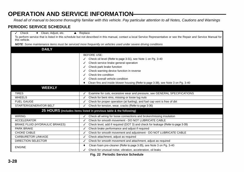
OPERATION AND SERVICE INFORMATION
3-28
Read all of manual to become thoroughly familiar with this vehicle. Pay particular attention to all Notes, Cautions and Warnings
PERIODIC SERVICE SCHEDULE ✓ Check ♦ Clean, Adjust, etc. ▲ ReplaceTo perform service that is listed in this schedule but not described in this manual, contact a local Service Representative or see the Repair and Service Manual forthis vehicle.
NOTE: Some maintenance items must be serviced more frequently on vehicles used under severe driving conditions
DAILYBEFORE USE:✓ Check oil level (Refer to page 3-31), see Note 1 on Pg. 3-40✓ Check service brake general operation✓ Check park brake function✓ Check warning device function in reverse✓ Check tire condition✓ Check overall vehicle condition♦ Clean fins and inside blower housing (Refer to page 3-38), see Note 3 on Pg. 3-40
WEEKLYTIRES ✓ Examine for cuts, excessive wear and pressure, see GENERAL SPECIFICATIONSWHEELS ✓ Check for bent rims, missing or loose lug nuts
FUEL GAUGE ✓ Check for proper operation (at fueling), and fuel cap vent is free of dirtSTARTER/GENERATOR BELT ✓ Check for tension, wear, cracks (Refer to page 3-36)
25 HOURS (includes items listed in previous table & the following)
WIRING ✓ Check all wiring for loose connections and broken/missing insulation
ACCELERATOR ✓ Check for smooth movement - DO NOT LUBRICATE CABLEBRAKE FLUID (HYDRAULIC BRAKES) ✓ Check level, add if required (DOT 3) and check for leakage (Refer to page 3-39)PARK BRAKE ✓ Check brake performance and adjust if required
CHOKE CABLE ✓ Check for smooth movement and adjustment - DO NOT LUBRICATE CABLECARBURETOR LINKAGE ✓ Check attachment, adjust as requiredDIRECTION SELECTOR ✓ Check for smooth movement and attachment, adjust as required
ENGINE♦ Clean foam pre-cleaner (Refer to page 3-35), see Note 3 on Pg. 3-40
✓ Check for unusual noise, vibration, acceleration, oil leaks
Fig. 22 Periodic Service Schedule

OPERATION AND SERVICE INFORMATION
3-29
Read all of manual to become thoroughly familiar with this vehicle. Pay particular attention to all Notes, Cautions and Warnings
STEERING ASSEMBLY ✓ Check for abnormal play, tightness of all hardwareTIE RODS/LINKAGES ✓ Check for excessive play, bent components or loose connections
REAR AXLE ✓ Check for leakage, add SAE 30 oil as required (Refer to page 3-36)
50 HOURS (includes items listed in previous tables & the following)
ENGINE▲ Change oil, DO NOT OVERFILL (Refer to page 3-32), see Note 1 and Note 2 on Pg. 3-40
✓ Check spark plug wires for cracks/loose connectionsEXHAUST ✓ Inspect/clean spark arresterFRONT AXLE ✓ Check for damage to axle and loose or missing hardware
FRONT SHOCK ABSORBERS ✓ Check for oil leakage and loose fastenersFRONT SPRINGS ✓ Check for loose hardware, cracks at attachmentsFRONT WHEEL ALIGNMENT ✓ Check for unusual tire wear, align if required
PARKING (PARK) BRAKE✓ Check for binding cables✓ Check for damage or wear♦ Lubricate as required, use light oil. DO NOT LUBRICATE CABLES
REAR SHOCK ABSORBERS ✓ Check for oil leakage, loose mounting hardwareENGINE ELECTRICAL SYSTEM ✓ Check coil/spark plug wires for cracks/loose connections
FUEL SYSTEM✓ Check for leaks at tank, cap, system lines, filters, pump, carburetor✓ Check system lines for cracks/deterioration
THROTTLE/GOVERNOR LINKAGE ✓ Check operation and governed speed
HARDWARE AND FASTENERS✓ Check for loose or missing hardware and components♦ Tighten or replace missing hardware
100 HOURS (includes items listed in previous tables & the following)
BATTERY ♦ Clean battery & terminals
ENGINE▲ Change oil filter (Refer to page 3-34), see Note 1 on Pg. 3-40
▲ Change air cleaner cartridge if damaged or dirty (Refer to page 3-35), see Note 3 on Pg. 3-40DIRECTION SELECTOR ✓ Check for wear and smooth movement (lubricate shaft with light oil if required)
KING PINS✓ Check for excessive play and tightness of retaining nuts♦ Lubricate, use wheel bearing grease
STEERING ASSEMBLY ♦ Lubricate unit and idler arm, use wheel bearing grease
Fig. 22 Periodic Service Schedule

OPERATION AND SERVICE INFORMATION
3-30
Read all of manual to become thoroughly familiar with this vehicle. Pay particular attention to all Notes, Cautions and Warnings
Note 1 - Change oil after first 8 hours, then after every 50 hours.
Note 2 - Change oil every 25 hours when operating under heavy loador in high temperatures.
Note 3 - Clean more often under dusty conditions or when airbornedebris is present. Clean foam pre-cleaner first and replace paper car-tridge if dirty. Replace either if showing signs of damage.
TIRE INSPECTIONTire condition should be inspected per the Periodic Service Schedule(Ref Fig. 22 on page 3-28). Inflation pressures should be checkedwhen the tires are cool. Be sure to install the valve dust cap after check-ing or inflating.
SEAT PROPThe driver seat is equipped with a prop for use every time the seat israised. To use, lift seat up against steering wheel to allow the prop tomove over the center console flange (Ref Fig. 23 on page 3-31).
RACK END BALL JOINT ♦ Lubricate, use wheel bearing greaseREAR AXLE ✓ Check for unusual noise and loose or missing mounting hardware
DRIVE BELT ✓ Check for cracks, fraying and excessive wear
250-300 HOURS or YEARLY (includes items listed in previous tables & the following)
FRONT WHEEL BEARINGS ✓ Check and adjust as required, see Technician’s Repair and Service ManualREAR AXLE ✓ Check lubricant, add lubricant (SAE 30 oil) as required (Refer to page 3-36)
SERVICE BRAKES♦ Clean, see Technician’s Repair and Service Manual✓ Check brake shoe linings, see Technician’s Repair and Service Manual
FUEL FILTER ♦ Replace (Refer to page 3-31)SPARK PLUGS ♦ Replace, gap new plugs (Ref. Capacities and Replacement Parts on page 3-42)(Refer to page 3-39)MUFFLER/EXHAUST ✓ Check mounting hardware; check for leaks at head and muffler gaskets
VALVES ✓ Check valve clearance, refer to Briggs & Stratton® Repair Manual (P/N 272144) for VANGUARD™ V-TwinOverhead Valve Engines
500 HOURS
REAR AXLE ▲ Replace lubricant
CYLINDER HEAD AND PISTONS ♦ Clean combustion chamber deposits, refer to Briggs & Stratton® Repair Manual (P/N 272144) for VANGUARD™ V-Twin Overhead Valve Engines
Fig. 22 Periodic Service Schedule

OPERATION AND SERVICE INFORMATION
3-31
Read all of manual to become thoroughly familiar with this vehicle. Pay particular attention to all Notes, Cautions and Warnings
REPLACING THE FUEL FILTERTo prevent a possible explo-sion, do not smoke near thefuel tank or in an area where
gasoline is being handled. Do not perform proce-dures involving fuel system near open fire or elec-trical items which could produce a spark.Do not handle gasoline in an area that is not ade-quately ventilated.Always wear safety glasses to prevent possibleeye injury from gasoline or gasoline vapor.
To replace fuel filter, use a pair of pliers to move clamps off ends of filterand pull filter up higher than the fuel pump to reduce the amount of gas
that will spill (Ref Fig. 24 on page 3-32). Remove hose coming fromfuel tank first and plug. Remove filter from hose going to fuel pump anddiscard.
Orient direction of new fuel filter according to theFLOW arrow on the side of filter.
Install new fuel filter and reposition the clamps over the inlet and outlet.
CHECKING THE OIL LEVELTool List Qty. Required
Clean cloth ............................................................................ 2
Never overfill the engine with oil,foaming may result and oil may
enter the breather system.
When adding oil between oil changes, do not mixbrands and viscosity grades of oil. Both the oil dip-
stick and fill cap must be in place before operating the engine.Failure to install the dipstick and fill cap will result in oil becomingcontaminated and/or oil being discharged into the engine com-partment.
Check oil level daily before starting the engine. The vehicle must be ona level surface with the parking brake engaged. Use a cloth to wipeclean the oil dipstick handle and oil fill cap (Ref Fig. 24 on page 3-32).This is necessary to prevent debris from falling into the engine.
Remove the dipstick and wipe off the entire area indicated with a cleancloth (Ref Fig. 25 on page 3-32).
Insert the dipstick fully into the dipstick tube and remove. Examine thelevel of oil on the dipstick. Oil should be at the FULL mark (Ref Fig. 26on page 3-32).
Fig. 23 Seat Prop
SeatProp
! !

OPERATION AND SERVICE INFORMATION
3-32
Read all of manual to become thoroughly familiar with this vehicle. Pay particular attention to all Notes, Cautions and Warnings
If oil is required, remove oil fill cap and add oil slowly to bring level to theFULL mark. Do not overfill.
Replace dipstick fully into dipstick tube and firmly replace the oil fill cap.
When adding oil between oil changes, do not mixbrands and viscosity grades of oil. Both the oil dip-
stick and fill cap must be in place before operating the engine.Failure to install the dipstick and fill cap will result in oil becomingcontaminated and/or oil being discharged into the engine com-partment.
CHANGING THE OILTool List Qty. Required
Pliers......................................................................................1
Oil drain pan ..........................................................................1
Clean cloth.............................................................................2
For maximum performance and longevity, the engine oil should bereplaced after the first five (5) to eight (8) hours of operation. After theinitial oil change, it should be changed per the Periodic Service Sched-ule (Ref Fig. 22 on page 3-28).
Fig. 24 Oil Fill Cap, Dipstick and Fuel Filter
Fig. 25 Clean Entire Dipstick
Fuel LineFrom Tank
FuelPump
FuelFilter
OilDipstick
Oil FillCap
ADD FULL
Fig. 26 Check Oil Level on Dipstick
Maximum oil levelDO NOT OVERFILL
ADD FULL

OPERATION AND SERVICE INFORMATION
3-33
Read all of manual to become thoroughly familiar with this vehicle. Pay particular attention to all Notes, Cautions and Warnings
The oil must be high quality detergent oil classified ‘For Service SF, SG,SH, SJ’ or higher. Do not use special additives and do not mix oil withgasoline. The selection of oil viscosity is dependent upon the climate inwhich the vehicle will be used. Most vehicles require SAE 30 oil; how-ever, vehicles used in cold climates will require a multi-viscosity oil (RefFig. 27 on page 3-33).
Synthetic oil meeting ILSAC GF-2, API certification mark and API ser-vice symbol with ‘SJ/CF ENERGY CONSERVING’ or higher, is anacceptable oil at all temperatures. Use of synthetic oil does not alterrequired oil change intervals.
Do not use special additives in recommended oil.
Do not mix oil with gasoline.
Air cooled engines run hotter thanautomotive engines. The use of non-
synthetic multi-viscosity oils (5W-30, 10W-30, etc.) intemperatures above 40° F (4° C) will result in higherthan normal oil consumption. When using a multi-viscosity oil, check oil level more frequently.
SAE 30 oil, if used below 40° F (4° C) will result in hardstarting and possible engine bore damage due toinadequate lubrication.
To reduce the possibility ofsevere injury, wear rubbergloves to protect skin from
exposure to hot, used oil and degreaser. Thesefluids contain chemicals known to cause cancer.
The oil should be changed with the engine warm. Park the vehicle on alevel surface, engage the parking brake and remove the key. Place a
drain pan under the engine. Wipe the oil fill cap clean with a cloth andremove the cap (Ref Fig. 24 on page 3-32).
Clean the area around the oil drain valve (Ref Fig. 28 on page 3-34).Open the valve and allow the oil to drain through the hole in the enginemounting plate. Close valve once oil has drained.
Add 1 quart (1 liter) of oil. Start and drive vehicle at a slow speed for 30seconds. Stop and turn off vehicle on a level surface and wait 30 sec-onds for the oil to settle to the bottom of the engine. Check for leaks.Slowly add more oil to bring level to the FULL mark on dipstick. Do notoverfill.
Replace dipstick fully into the dipstick tube and firmly replace the oil fillcap.
! !
Fig. 27 Oil Viscosity Chart
-20 0 20 40 60 80 100
-30 -20 -10 0 10 20 30 40C
F0
0
SAE 30
(Air Temperature)
5W-30, 10W-30
Synthetic 5W-20, 5W-30

OPERATION AND SERVICE INFORMATION
3-34
Read all of manual to become thoroughly familiar with this vehicle. Pay particular attention to all Notes, Cautions and Warnings
CHANGING THE OIL FILTERTool List Qty. Required
Oil filter wrench, to fit 3" (76 mm) oil filter.............................. 1
Oil drain pan .......................................................................... 1
Clean cloth ............................................................................2
Clean the area around the oil filter and oil drain. Drain engine oil per‘Changing the Oil’ and remove oil filter (Ref Fig. 28 on page 3-34).Make sure the seal came off with filter and is not stuck to the engine.
Wipe around the sealing surface of filter mount with a clean, lint freecloth. Lightly oil the seal on the new filter with fresh, clean oil. Screw fil-ter on by hand until the seal contacts the filter mount. Tighten 1/2 to 3/4turn more. Refill engine with new oil per ‘Changing the Oil’.
LUBRICATION
Do not use more than three (3)pumps of grease in each grease
fitting at any one time. Excess grease may causegrease seals to fail or grease migration into areas thatcould damage components.
Putting more than three pumps of grease in a grease fitting could dam-age grease seals and cause premature bearing failure (Ref Fig. 29 onpage 3-34).
Fig. 28 Oil Drain and Filter
Oil DrainValve
Oil Filter
Fig. 29 Lubrication Points
SteeringUnit
Ball Joint on Rack and Rod
King PinKing PinIdler Arm

OPERATION AND SERVICE INFORMATION
3-35
Read all of manual to become thoroughly familiar with this vehicle. Pay particular attention to all Notes, Cautions and Warnings
AIR CLEANER INSPECTION AND REPLACEMENTThe air cleaner is a dual filter cleaner, equipped with a foam pre-cleanerover a conventional paper cartridge. The filters must be serviced perthe Periodic Service Schedule (Ref Fig. 22 on page 3-28) for optimumengine life and performance.
To prevent engine damage, becareful not to let debris fall into the
carburetor when servicing the air cleaner.
To prevent water entering air cleaner and causingstarting or engine problems, replace air cleaner covermaking sure the entire flange around the bottom ofthe cover fits over the top edge of the air cleaner base.Secure with the spring clips.
Access the filters by unsnapping the spring clip on each side of the aircleaner and removing the air cleaner cover (Ref Fig. 30 on page 3-35).If necessary, vacuum or wipe out any loose dirt or trash from the aircleaner base.
Pre-Cleaner ServiceThe foam pre-cleaner is to be used dry. Do not putoil on the foam.
Carefully remove pre-cleaner from cartridge and wash it in liquid deter-gent and water. Rinse. Dry by squeezing pre-cleaner in a clean cloth.Do not put oil on the pre-cleaner. Install pre-cleaner over cartridge.Replace air cleaner cover making sure the entire flange around bottomof cover fits over the top edge of the air cleaner base. Secure with thespring clips.
Cartridge Service
Do not use petroleum solvents,pressurized water, or compressed
air to clean cartridge. Doing so will damage thecartridge and will damage the engine.
The paper cartridge is a dry unit. Do not use oil onthe cartridge.
Fig. 30 Air Cleaner
Plate
Air CleanerCover
Air CleanerBase
Knob
Cartridge
Pre-cleaner

OPERATION AND SERVICE INFORMATION
3-36
Read all of manual to become thoroughly familiar with this vehicle. Pay particular attention to all Notes, Cautions and Warnings
Unscrew the knob securing the cartridge to the air cleaner base andremove plate. Remove cartridge and inspect. Replace if too dirty toclean or at the first sign of filter paper deterioration. Clean cartridge bygently tapping on a flat surface.
To reduce the possibility of enginedamage from ingesting unfiltered
air, ensure plate is centered and correctly seated ontop of cartridge before securing with knob.
Place cartridge in air cleaner base. Install plate centered and fullyseated on top of cartridge. Secure with knob and install pre-cleanerover cartridge.
Replace air cleaner cover making sure that the entire flange around thebottom of the cover fits over the top edge of the air cleaner base.Secure with the spring clips.
REAR AXLEThe rear axle is provided with a lubricant level check plug located onthe driver side at the rear of the housing (Ref Fig. 31 on page 3-36).Unless leakage is evident, an annual lubricant check is sufficient.
Checking the Lubricant LevelTool List Qty. Required
Wrench, 13 mm..................................................................... 1
Funnel ................................................................................... 1
Clean area around check and fill plugs. Remove the check plug. Thecorrect lubricant level is just below the bottom of the threaded hole. Iflubricant is to be added, remove the fill plug and add lubricant (SAE 30oil) using a funnel. Add lubricant slowly until lubricant starts to seep
from the check plug hole. Install the check plug and the fill plug. In theevent that the lubricant is to be replaced, a drain plug is provided at thebottom of the differential housing. Capacity of axle is 48 oz. (1.4 liters).
STARTER/GENERATOR BELT TENSIONTool List Qty. Required
Belt tension gauge.................................................................1
Wrench, 3/4" ..........................................................................1
Wrench, 1/2" ..........................................................................2
Socket, 1/4" hex bit, 3/8" drive...............................................1
Ratchet, 3/8" drive .................................................................1
Socket, 3/4", 3/8" drive ..........................................................1
Socket, 1/2", 3/8" drive ..........................................................1
Pry bar ...................................................................................1
Torque wrench, 3/8" drive, ft. lbs. ..........................................1
Fig. 31 Add, Check and Drain Rear Axle Lubricant
Check Plug
Drain Plug

OPERATION AND SERVICE INFORMATION
3-37
Read all of manual to become thoroughly familiar with this vehicle. Pay particular attention to all Notes, Cautions and Warnings
The starter/generator belt tension should be checked after the first 15-20 hours of operation and set to 75 - 80 lbs. (34 - 36 kg).
A loose belt can cause audible vibration andsqueal.
Tighten a new starter/generator belt to 90 - 110 lbs. (41 - 50 kg) tensionwhen a gauge is applied half way between the two pulleys (Ref Fig. 32on page 3-37).
Although not as accurate, the belt may be depressed with a finger. Amaximum deflection of 3/8" (1 cm) is acceptable for a new belt (RefFig. 33 on page 3-37).
Tighten an existing belt to 75 - 80 lbs. (34 - 36 kg) tension using thesame technique and inspect for cracking or wear. A maximum deflec-tion of 1/2" (13 mm) is acceptable.
Adjusting the BeltLoosen front and back pivot bolts of starter/generator (Ref Fig. 34 onpage 3-37).
Loosen adjusting bolt. Use pry bar to force starter/generator towardsfront of vehicle until proper belt tension is achieved. Hold starter/gener-ator in place and tighten adjusting bolt.
Tighten pivot bolts to 25 ft. lbs. (35 Nm) torque.
Fig. 32 Check Belt Tension with Gauge
Fig. 33 Check Belt Tension with Finger
Fig. 34 Adjust Belt Tension
3/8" (1 cm) Max. Deflection for New Belt
1/2" (1.3 cm) Max. Deflection for Existing Belt
Pivot Bolt
Adjusting Bolt

OPERATION AND SERVICE INFORMATION
3-38
Read all of manual to become thoroughly familiar with this vehicle. Pay particular attention to all Notes, Cautions and Warnings
BATTERY CLEANING
To reduce the possibility of damageto vehicle or floor, neutralize acid
before rinsing battery.
To reduce the possibility of damage to electricalcomponents while cleaning, do not use a pressurewasher.
Cleaning should take place per the Periodic Service Schedule (Ref Fig.22 on page 3-28).
When cleaning the outside of the battery and terminals, first spray witha solution of sodium bicarbonate (baking soda) and water to neutralizeany acid deposits before rinsing with clear water.
Use of a water hose without first neutralizing any acid, will move acidfrom the top of the battery to another area of the vehicle or storage facil-ity where it will attack the metal structure or the concrete/asphalt floor.Additionally, a residue will be left on the battery which is conductive andwill contribute to the discharge of the battery.
To reduce the possibility ofbattery explosion that couldresult in severe injury or
death, do not use metallic spray wand to cleanbattery and keep all smoking materials, openflame or sparks away from the battery.
The correct cleaning technique is to spray the top and sides of the bat-tery with a solution of sodium bicarbonate (baking soda) and water.This solution is best applied with a plastic spray bottle. The solutionshould consist of 2 teaspoons (10 ml) of sodium bicarbonate (bakingsoda) mixed with 1 quart (1 liters) of clear water (Ref Fig. 35 on page 3-
38). In addition to the battery, special attention should be paid to metalcomponents adjacent to the battery which should also be sprayed withthe sodium bicarbonate (baking soda) solution.
Allow the solution to sit for at least three minutes; use a soft bristlebrush or cloth to wipe the tops of the battery to remove any residue thatcould contribute to the self discharge of the battery. Rinse the entirearea with low pressure clear water. Do not use a pressure washer.
AIR INTAKE AND COOLING FINSTo prevent possible burns,engine parts should be keptclean to reduce risk of over-
heating and ignition of accumulated debris.
! !Fig. 35 Preparing Acid Neutralizing Solution
1 quart(1 liter)
Clear Water
2 Teaspoons (10 ml)Sodium Bicarbonate
(Baking Soda)
PlasticSprayBottle
! !

OPERATION AND SERVICE INFORMATION
3-39
Read all of manual to become thoroughly familiar with this vehicle. Pay particular attention to all Notes, Cautions and Warnings
After every off road use, allow to cool and then check for a build up ofdirt and debris in the air intake and cooling fins. Dirt and debris mayclog the engine’s air cooling system. Clean areas shown to preventengine damage (Ref Fig. 36 on page 3-39). Keep linkages, springs andcontrols clean. Keep area around muffler free of any combustible mate-rial.
SPARK PLUGSTool List Qty. Required
Spark plug socket, 5/8", 1/2" drive .........................................1
Ratchet, 1/2" drive .................................................................1
Plug gauge, wire type ............................................................1
Anti-seize compound ..........................................................AR
Torque wrench, 1/2" drive, ft. lbs............................................1
Use care not to over-tighten the
plug. Over-tightening can cause damage to thealuminum cylinder head threads.
Remove and inspect the spark plugs at intervals per the Periodic Ser-vice Schedule (Ref Fig. 22 on page 3-28). All new spark plugs shouldbe properly gapped before installation (Ref Fig. 38 on page 3-42).Apply a light coat of anti-seize compound and tighten to 15 ft. lbs. (20Nm) torque.
Fouled spark plugs are indicated by a wet, black appearance. Thiscould be caused by a dirty air filter element or other restrictions in the airintake system. Incorrectly adjusted valves, spark plug wires which arein poor condition or poor quality fuel could also contribute to the prob-lem.
Do not sand blast spark plugs. They should becleaned by scraping or wire brushing by hand and
washing in a commercial solvent.
BRAKESThe master cylinder is located under the driver side seat.
It is important to maintain proper fluid levels in the brake master cylin-der. The fill cap for the cylinder is located under the seat. When check-ing the fluid, wipe off any dirt from the fill cap before removing it toprevent contamination. Fluid level should be maintained at 1/4" (6 mm)below the top of the housing. Use DOT 3 automotive brake fluid.
Daily Brake TestTo prevent severe injury ordeath resulting from operat-
Fig. 36 Cleaning Air Intake and Cooling Fins
AirIntake
CoolingFins
! !

OPERATION AND SERVICE INFORMATION
3-40
Read all of manual to become thoroughly familiar with this vehicle. Pay particular attention to all Notes, Cautions and Warnings
ing a vehicle with improperly operating brake sys-tem, the braking system must be properlymaintained. All driving brake tests must be donein a safe location with regard for the safety of allpersonnel.
After the vehicle has been put into service, it is recommended that thebrakes be checked daily by performing the following test:
Depress the brake pedal. The pedal should have some free travel andthen become hard. A brake pedal that has no free travel, excessivefree travel or a spongy feel is indicating that a brake inspection isrequired. A brake pedal that falls after it is applied indicates a leak in themaster or wheel cylinders. Check for adequate brake fluid level. Adjustbrakes if required and inspect system for fluid leaks.
PROLONGED STORAGETo prevent serious injury ordeath resulting from a possi-ble explosion:
Do not handle fuel in an area that is not ade-quately ventilated. Do not smoke near the fueltank or refuel near open flame or electricalitems which could produce a spark.Store vehicle in a clean, dry area. Do not storein same area as a stove, furnace, water heater,or other appliance that uses a pilot light or hasa device that can create a spark.When refueling, inspect the fuel cap for leaks orbreaks that could result in fuel spillage.
Always wear safety glasses while refueling toprevent possible eye injury from gasoline orgasoline vapor.Keep hands, clothing and jewelry away frommoving parts. Use care not to contact hotobjects. Raise the rear of the vehicle and sup-port on jack stands before attempting to run theengine.
Preparing the engine for a prolonged storage period (30 days or more)calls for a few simple steps to prevent a build up of varnish and gum inthe carburetor and corrosion in the engine.
• Raise the rear of the vehicle and support on jack stands. Refer to‘Lifting the Vehicle’ for proper lifting procedure and safety informa-tion.
• Disconnect the fuel hose at the fuel tank and plug hose.
• With proper ventilation, depress the accelerator pedal and allowengine to run until it stops due to lack of fuel.
• Remove spark plugs (Refer to page 3-39) and pour about 1 oz.(30 ml) of engine oil into each cylinder. Replace spark plugs,ground spark plug wires and use starter to turn engine over a fewseconds to distribute oil.
• Add a gasoline additive to the tank in accordance with the manu-facturer’s recommendations.
• Reattach fuel line to tank and drive the vehicle for several minutesto circulate the additive through the carburetor.
• While engine is still warm, change oil (Refer to page 3-32).• Clean body, chassis and engine of debris, mud, chaff or grass
(Refer to page 3-38).
! !

OPERATION AND SERVICE INFORMATION
3-41
Read all of manual to become thoroughly familiar with this vehicle. Pay particular attention to all Notes, Cautions and Warnings
HARDWAREPeriodically, the vehicle should be inspected for loose fasteners. Fas-teners should be tightened in accordance with the Torque Specifica-tions table (Ref Fig. 37 on page 3-41).
Use care when tightening fasteners and refer to the Technician’sRepair and Service Manual for specific torque values.
Generally, three grades of hardware are used in the vehicle. Grade 5hardware can be identified by the three marks on the hexagonal headand grade 8 hardware is identified by 6 marks on the head. Unmarkedhardware is Grade 2 (Ref Fig. 37 on page 3-41).
Fig. 37 Torque Specifications and Bolt Grades
ALL TORQUE FIGURES ARE IN FT. LBS. (Nm)
BOLT SIZE
Grade 2
1/4" 5/16" 3/8" 7/16" 1/2" 9/16" 5/8" 3/4" 7/8" 1"
Unless otherwise noted in text, tighten all hardware in accordance with this chart.This chart specifies 'lubricated' torque figures. Fasteners that are plated or lubricated when
installed are considered 'wet' and require approximately 80% of the torque required for 'dry' fasteners.
4(5)
8(11)
15(20)
24(33)
35(47)
55(75)
75(102)
130(176)
125(169)
190(258)
Grade 5
Grade 8
6(8)
13(18)
23(31)
35(47)
55(75)
80(108)
110(149)
200(271)
320(434)
480(651)
6(8)
18(24)
35(47)
55(75)
80(108)
110(149)
170(230)
280(380)
460(624)
680(922)
BOLT SIZE
Class 5.8(Grade 2)
M4 M5 M6 M8 M10 M12 M14
1(2)
2(3)
4(6)
10(14)
20(27)
35(47)
55(76.4)
Class 8.8(Grade 5)
2(3)
4(6)
7(10)
18(24)
35(47)
61(83)
97(131)
Class 10.9(Grade 8)
3(4)
6(8)
10(14)
25(34)
49(66)
86(117)
136(184)
5.8
8.8
10.9

OPERATION AND SERVICE INFORMATION
3-42
Read all of manual to become thoroughly familiar with this vehicle. Pay particular attention to all Notes, Cautions and Warnings
CAPACITIES AND REPLACEMENT PARTS
Fig. 38 Capacities and Replacement Parts
Fuel Tank / Fuel
Engine Oil
Oil Filter
Air Cleaner Filter
Pre-Cleaner Filter
Spark Plugs
Starter/Generator Belt
Clutch Belt
Rear Axle Oil
Fuse
Headlight Bulb
Turn Signal Bulb
Tail Light Bulb
6.0 gal (22.5 liters) 87 Octane
1 1/2 qt (1.4 liters)
40 oz (1.2 liters)
15 amp (P/N 35212-G01)
7.5 amp (P/N 35212-G05)
P/N 20209-G3
#1157 (P/N 21759-G1)
#1157 (P/N 21759-G1)
P/N 492932
P/N 394018
P/N 272490
CHAMPION RC12YC (P/N 491055)
.030" (.76 mm) Gap
P/N 75690-G01
P/N 75691-G01

4-1
GENERAL SPECIFICATIONSST 480
STANDARD EQUIPMENT:BATTERY............................... One 12 Volt Maintenance Free (515 CCA, 82 Minute
Reserve)ENGINE.................................. 16 H.P. (11.9 kW) 29.2 ci (480 cc) Twin Cylinder, Overhead
ValvePressurized Lubrication with Spin Off FilterMagnetron™ Ignition with Transistor ModuleReplaceable Dry Cartridge Air Filter with Pre-Filter & Remote IntakeFixed Jet Bowl Carburetor, Pulse Fuel Pump
TRANSAXLE.......................... 13.32:1 Helical geared with Differential Lock and Ground Speed Governor
TRANSMISSION................... Automatic Continuously Variable Transmission (CVT)FUEL TANK............................ 6 Gallon (23 Liters) Tank. 36 lbs. (16 kg) Fuel WeightBRAKES................................. Dual Rear Wheel, Self-Adjusting Hydraulic Drum BrakesPARKING BRAKE................. Hand Operated Mechanical Parking BrakeFRONT SUSPENSION ........ Leaf Springs with Hydraulic Shock AbsorbersREAR SUSPENSION........... Leaf Springs with Hydraulic Shock AbsorbersSTEERING............................. Single Reduction Rack & PinionSTEERING WHEEL.............. Dual HandgripsSEATING................................ Cushion Foam/Vinyl Cover Bucket Seats, Hip Restraint/Hand
HoldSEATING CAPACITY............ Operator & 1 PassengerTOTAL LOAD CAPACITY..... 800 lbs. (365 kg) Including Operator, Passenger, Accessories
& Cargo500 lbs. (230 kg) Maximum Bed Load
SPEED.................................... 16.5 mph (26.5 kph) MaxCHASSIS................................ Powder Coated (DuraShield™), Welded Tubular SteelVEHICLE PROTECTION..... Tubular Steel Front Bumper with Brush GuardsBODY...................................... Flexible Impact Resistant DuraShield™ Injection Molded
TPO (Thermoplastic Olefin) with Base Coat/Clear Coat Front Cowl. DuraShield™ Powder Coated Steel Rear Body
STANDARD COLOR(S) ....... ST Series: Hunter Green; ST ADVANTAGE Series: RealTree® Advantage Camo Body and Load Bed
DASH PANEL ........................ Scuff Resistant Glass Fiber Reinforced Plastic (Thermoplastic Olefin) with 4 Drink Holders
LOAD BED............................. 48" (122 cm) W x 40" (102 cm) L x 12" (30 cm) D; 13.3 Cubic feet(.38 m3); with Full Bed & Tailgate Liner & Electric Dump
LOAD BED FEATURES....... Hinged Removable Tailgate, Removable Bed SidesLIGHTING/HORN (Standard)Dual Halogen Headlights, HornTIRES (Standard)................... 22 x 9 - 10 Stryker I® (Uni-directional)TIRE PRESSURE................. 12 - 16 psi (85 - 110 kPa)WEIGHT (Without Fuel)........ 1050 lbs (480 kg)OPERATING CONTROLS& INSTRUMENTATION........ Removable Key, ‘Deadman’ Accelerator Control, Direction
Selector, Audible Reverse Warning, Analog Fuel Gauge, Low Oil Pressure Indicator and 12 Volt Power Outlet
OPTIONS/ACCESSORIES:Ash Tray Top (Sun Canopy)Black Hubcaps Trailer HitchBrake Ligahts & Taillights Turn SignalsGlove Box Locking (Driver & Passenger Side) Weather Protection EnclosureHour Meter Winch, ElectricPaint Color (Custom) Windshield One-Piece (Top Required)
LexanRear View Mirror (Requires Top) Windshield Fold Down (Top Required)
LexanReceiver, Front & RearTires 21 x 9 - 10 Work Mate® (Uni-directional) @ 12 psi (85 kPa)Tires 20 x 10 - 10 Turf Saver®
Tool Box
Specifications subject to change without notice.

4-2
GENERAL SPECIFICATIONS
Fig. 1 Vehicle Dimensions
12"(31 cm)
34"(86 cm)
6"(15 cm)
Ground Clearance
110.5" (281 cm)
15"(38 cm)
49"(125 cm)
48"(122 cm)
77" (196 cm)
40" (102 cm)
Front38" (96 cm)
Rear38.5" (97 cm)
78"(198 cm)
or75"
(191 cm)with Brush
GuardCage

4-3
GENERAL SPECIFICATIONS
Fig. 2 Vehicle Incline Specifications
Maximum Recommended Side Tilt25% or 14˚ Max.
Maximum Recommended Ramp Grade25% or 14˚ Max.

4-4
GENERAL SPECIFICATIONS
Fig. 3 Vehicle Turning Clearance Diameter and Intersecting Aisle Clearance
TURNING CLEARANCE DIAMETER
Approx. 23.5 ft (7.2 m)
83"(211 cm)
83"(211 cm)
INTERSECTINGAISLE CLEARANCE

5-1
LIMITED WARRANTY
EMISSION CONTROL SYSTEM WARRANTY STATEMENT
(Owner’s Defect Warranty Rights and Obligations)Refer to the Briggs & Stratton® Operating & Maintenance Instructions, providedwith vehicle, for Emission Control System Warranty information.
ENGINE OWNER WARRANTY POLICYRefer to the Briggs & Stratton® Operating & Maintenance Instructions, providedwith vehicle, for Engine Warranty information.

5-2
LIMITED WARRANTY
Notes:

6-1
DECLARATION OF CONFORMITY

6-2
DECLARATION OF CONFORMITY
Notes:

Appendix A-1
LABELS AND PICTOGRAMS
Fig. 1 Label Locations
35962G01
!
!
RF
< 14˚ 25%
P
F
!
< 14˚ 25%35962-G01
74443G01See Following Pages For Explanation Of These Pictograms: (1,2)
!
1. To Prevent Roll-Back On a Hill From a Stopped Position
3. Fully Release Park Brake
2. Apply Service Brake With Left Foot
4. Depress Accelerator While Releasing Service Brake As Vehicle Starts 74443G01
See Following Pages For
Explanation Of These
Pictograms: (2,3,4,6,9,36,37,
38,39,40,29)
See Following PagesFor Explanation OfThese Pictograms:
(19,43,44,45)
75808G01
OFFON
75808-G01
H O2
1 2 3
PP
PP PP
74093-G01
74093G01See Following Pages For Explanation Of These Pictograms: (1,23,27,18,20,22,17,15)
See Following Pages For Explanation Of These Pictograms:
(1,2,46,47,48)
75696G01
75696G01
75851G01
75851G01
DO NOT TAMPER WITH OR CHANGE THIS ADJUSTMENT OF THEGOVERNOR. FAILURE TO COMPLY COULD RESULT IN SERIOUSPERSONAL INJURY AND WILL VOID THE VEHICLE WARRANTY.
WARNING
24880G01
See Following PagesFor Explanation OfThese Pictograms:
(1,35)

Appendix A-2
LABELS AND PICTOGRAMS
Fig. 2 Label Locations (Continued)
WARNING
Keep entire body
inside car.
27653G01
See Following Pages For Explanation Of Pictogram: (49)
PP
MAX250 lbs.114 kg
MAX 4 in.10 cm
MAX14o / 25%
!35980G01
35980G02 See Following Pages For Explanation Of These Pictograms: (1,2,12,10,8,7,5,11)
WARNING
Windshields do notprovide protectionfrom golf balls orother flying objects.
EGWHL14
See Following Pages For Explanation Of Pictogram: (30)
35493G01
See Following PagesFor Explanation Of
This Pictogram: (28) Pb
35493-G01
71489G01
See Following PagesFor Explanation OfThese Pictograms:
(1,2)

Appendix A-3
LABELS AND PICTOGRAMS
Fig. 3 Pictogram Definitions
WARNING
READ MANUAL
!
WARNINGUSE CAUTION ININCLEMENT WEATHER
WARNINGDO NOT OPERATEIF USING ALCOHOLOR DRUGS
MAX14˚ / 25%
MAXIMUM CROSS HILL/RAMP ANGLE AS SPECIFIED
!
< 14˚ 25%
WARNINGMAXIMUM CROSSHILL/RAMP ANGLE ASSPECIFIED
LOAD WITHHIGH CENTEROF GRAVITY COULD RESULTIN TIP OVER
MAXxx inxx cm
LOADCENTEROF GRAVITY,MAXIMUMHEIGHT
1.
2.
3.
4.
5.
6.
7.
8.

Appendix A-4
LABELS AND PICTOGRAMS
Fig. 4 Pictogram Definitions (Continued)
!
< 14˚ 25%
WARNINGREAD MANUAL FOR MAXIMUM LOAD BEDCAPACITY.MAXIMUMRAMP/HILL
MAXxxx lbs.xxx kg
SECURE LOADAS FAR FORWARDAS POSSIBLE.MAXIMUM LOADBED CAPACITY
DO NOT RIDE INLOAD BED
PP
DANGER OF EXPLOSIONDO NOT FILL GAS CAN IN LOAD BED
x inx inxx cmxx cm
MAX LOADMAX LOADXXX LBSXXX LBSXXX KGXXX KG
WARNINGMAXIMUMLOAD &CENTER OF GRAVITY.KEEP LOAD AS FAR FORWARDAS POSSIBLE.DO NOT RIDE IN LOAD BED
KEEP HANDS& FINGERSAWAY FROMDUMP BED.DO NOTSTAND BEHINDDUMP BED
9.
10.
11.
12.
13.
14.

Appendix A-5
LABELS AND PICTOGRAMS
Fig. 5 Pictogram Definitions (Continued)
1 3H O2PP
CLEAN UPGASOLINE SPILLS WITHWATER BEFORESTARTING ENGINE
PP
UNLEADED GASOLINE
PP
GROUND FUEL PUMP
PP
DO NOT SPILL FUELON A HOTENGINE
NO TAMPERING.KEEP HANDS OUT
NEGATIVE GROUND BATTERY
DO NOT CONNECT POSITIVE BATTERY TERMINAL TO GROUND
SHORTING BATTERY TERMINALS MAY CAUSE EXPLOSION
DO NOT EXPOSE TO FLAME
WARNINGCORROSIVE
WARNINGLETHALVOLTAGE
WARNINGEXPLOSIVE
LOW OIL PRESSURE
15.
16.
17.
18.
19.
20.
21.
22.
23.
24.
25.
26.
27.

Appendix A-6
LABELS AND PICTOGRAMS
Fig. 6 Pictogram Definitions (Continued)
DO NOTDISPOSE OFBATTERIESIN LANDFILL
DO NOT DRIVE ON HIGHWAY
WINDSHIELDSDO NOTPROVIDE PROTECTION FROMFLYING OBJECTS
BATTERIES ARE HEAVY. USE CARE LIFTING
USE INSULATED TOOLS
WEAR EYE PROTECTION
NO SMOKING
HOT SURFACE
28.
29.
30.
31.
32.
33.
34.
35.
OPERATE FROM DRIVERS SIDE ONLY
36.

Appendix A-7
LABELS AND PICTOGRAMS
Fig. 7 Pictogram Definitions (Continued)
KEEP ARMS AND LEGS WITHIN VEHICLE
F
TO OPERATE VEHICLE IN FORWARD:✱ TURN KEY TO ON✱ MOVE DIRECTION SELECTOR TO FORWARD✱ DEPRESS ACCELERATOR PEDAL AND ACCELERATE SMOOTHLY
KEEP CLEARHAND OR FINGERS CANBE TRAPPED
37.
38.
42.
P
F
R
TO OPERATE VEHICLE IN REVERSE:✱ TURN KEY TO ON✱ MOVE DIRECTION SELECTOR TO REVERSE✱ AN AUDIBLE DEVICE WILL SOUND✱ DEPRESS ACCELERATOR PEDAL AND ACCELERATE SMOOTHLY
TO LEAVE A GASOLINE POWEREDVEHICLE IN PARK:✱ APPLY PARKING BRAKE✱ TURN KEY TO OFF✱ MOVE DIRECTION SELECTOR TO FORWARD
P
N
TO LEAVE AN ELECTRIC POWEREDVEHICLE IN PARK:✱ APPLY PARKING BRAKE✱ TURN KEY TO OFF✱ MOVE DIRECTION SELECTOR TO NEUTRAL
39.
40.
41.

Appendix A-8
LABELS AND PICTOGRAMS
Fig. 8 Pictogram Definitions (Continued)
ON
OFF
ONPOSITION
OFFPOSITION
HEADLIGHTS
UNLOCKED
43.
44.
45.
46.
LOCKED
DIFFERENTIAL LOCKED
47.
48.
49.WARNINGKEEP ENTIRE BODYINSIDE CAR


Textron Golf, Turf & Specialty ProductsP.O. Box 388 Augusta, Georgia 30903-0388 USAInside USA Phone: 1-800-241-5855, FAX: 1-800-448-8124Outside USA Phone: 010-1-706-798-4311, FAX: 010-1-706-771-4609
Copyrighted MaterialThis manual may not be reproduced in whole or in part without the express permission of Textron Golf, Turf & Specialty ProductsTechnical Communications Department
P/N 28578-G03-GBISSUED: 07/2002