OWNER’S MANUAL · PDF fileowner’s manual installation operation maintenance 5....
50
OWNER’S MANUAL INSTALLATION OPERATION MAINTENANCE 5
Transcript of OWNER’S MANUAL · PDF fileowner’s manual installation operation maintenance 5....

OWNER’S MANUAL
INSTALLATIONOPERATION
MAINTENANCE
5

CONTENTSINTRODUCTION
SAFETY INSTRUCTIONS
SPECIFICATIONS
PRE-INSTALLATION CHECKLIST
COMPONENTSAxis Plate, Generator AxisBlades, LoctiteConnection ArmsBolts
WIRING DIAGRAMS
GETTING STARTEDPositioning your TurbineTower and FoundationWires, UsageAssembly requirements, Important considerations
INSTALLATIONGenerator Axis and Top PlateLower connecting armUpper connecting armBladesGenerator and Turbine
COMMISSIONING CHECKLIST GRID-TIE
OPERATION
FREQUENTLY ASKED QUESTIONS
WARRANTY INFORMATION
MAINTENANCE
GREEN BEST PRACTICES
TECHNICAL SUPPORT
NOTES
1
2
3
4
5
6789
10
11121314-18
19
20-282021-2223-2425-2627-28
29
31
32
33-37
38-41
42
back

Dear VisionAIR5 Owner,
Congratulations on purchasing your VisionAIR5 Vertical Axis Wind Turbine (VAWT) and welcome to our family.
Enclosed in this manual is information regarding installation, operation and maintenance of your new turbine.Please read through it before installing and using your turbine.
These installation and maintenance instructions contain important information for the safe installation and maintenance of the VisionAIR5 vertical axis wind turbine. The turbine should only be installed by qualified personnel such as an employee of a UGE distributor, licensed contractor or certified electrician. Yearly maintenance checks should be performed by a person with similar qualifications. The owner should retain a copy of this manual for reference and to give to future maintenance personnel.
This manual should be used in conjunction with electronics installation manuals, tower installation manuals, and the UGE Electrical Supplement. These manuals can be found on the website of the tower and electronics suppliers respectively or can be provided by your UGE distributor.
In this manual you will see several checklists to guide you through the installation of the turbine. You will be able to follow these step-by-step instructions to insure your installation is completed correctly.
To activate your warranty, please go to www.ugei.com/warranty_form.php. You must activate your warranty before allowing your turbine to spin.
We would like to hear from you with any questions or comments that you have. Please contact us during working hours (Monday-Friday 9:00am to 6:00 pm - US Eastern Time) at:
Telephone: +1 (917) 720-5685Website: www.ugei.comEmail: [email protected]
Sincerely,
INTRODUCTION
2
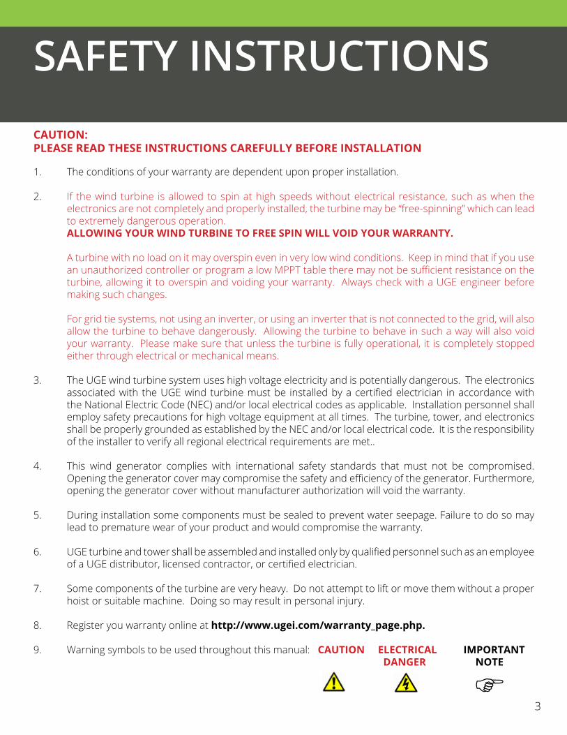
The conditions of your warranty are dependent upon proper installation.
If the wind turbine is allowed to spin at high speeds without electrical resistance, such as when the electronics are not completely and properly installed, the turbine may be “free-spinning” which can lead to extremely dangerous operation. ALLOWING YOUR WIND TURBINE TO FREE SPIN WILL VOID YOUR WARRANTY.
A turbine with no load on it may overspin even in very low wind conditions. Keep in mind that if you use an unauthorized controller or program a low MPPT table there may not be sufficient resistance on the turbine, allowing it to overspin and voiding your warranty. Always check with a UGE engineer before making such changes.
For grid tie systems, not using an inverter, or using an inverter that is not connected to the grid, will also allow the turbine to behave dangerously. Allowing the turbine to behave in such a way will also void your warranty. Please make sure that unless the turbine is fully operational, it is completely stopped either through electrical or mechanical means.
The UGE wind turbine system uses high voltage electricity and is potentially dangerous. The electronics associated with the UGE wind turbine must be installed by a certified electrician in accordance with the National Electric Code (NEC) and/or local electrical codes as applicable. Installation personnel shall employ safety precautions for high voltage equipment at all times. The turbine, tower, and electronics shall be properly grounded as established by the NEC and/or local electrical code. It is the responsibility of the installer to verify all regional electrical requirements are met.. This wind generator complies with international safety standards that must not be compromised. Opening the generator cover may compromise the safety and efficiency of the generator. Furthermore, opening the generator cover without manufacturer authorization will void the warranty.
During installation some components must be sealed to prevent water seepage. Failure to do so may lead to premature wear of your product and would compromise the warranty.
UGE turbine and tower shall be assembled and installed only by qualified personnel such as an employee of a UGE distributor, licensed contractor, or certified electrician.
Some components of the turbine are very heavy. Do not attempt to lift or move them without a proper hoist or suitable machine. Doing so may result in personal injury.
Register you warranty online at http://www.ugei.com/warranty_page.php.
Warning symbols to be used throughout this manual: CAUTION ELECTRICAL IMPORTANT DANGER NOTE
1.
2.
3.
4.
5.
6.
7.
8.
9.
CAUTION: PLEASE READ THESE INSTRUCTIONS CAREFULLY BEFORE INSTALLATION
SAFETY INSTRUCTIONS
3
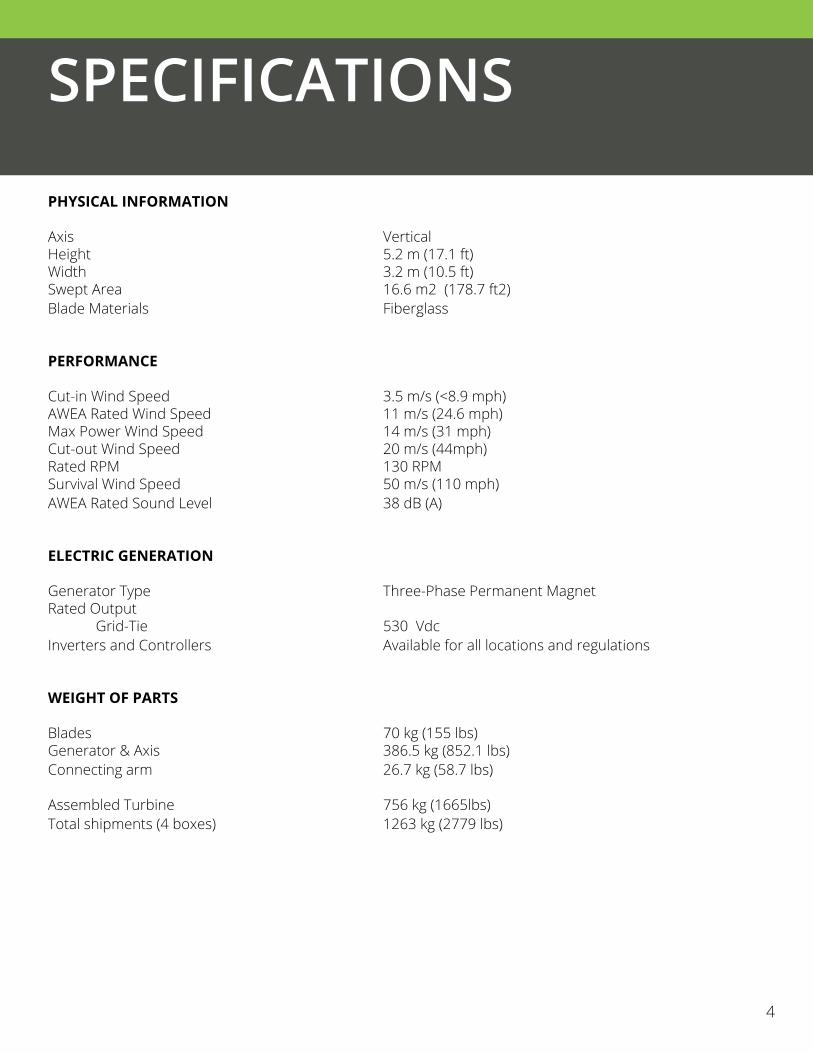
PHYSICAL INFORMATION
Axis VerticalHeight 5.2 m (17.1 ft)Width 3.2 m (10.5 ft)Swept Area 16.6 m2 (178.7 ft2)Blade Materials Fiberglass
PERFORMANCE
Cut-in Wind Speed 3.5 m/s (<8.9 mph)AWEA Rated Wind Speed 11 m/s (24.6 mph)Max Power Wind Speed 14 m/s (31 mph)Cut-out Wind Speed 20 m/s (44mph)Rated RPM 130 RPMSurvival Wind Speed 50 m/s (110 mph) AWEA Rated Sound Level 38 dB (A)
ELECTRIC GENERATION
Generator Type Three-Phase Permanent MagnetRated Output Grid-Tie 530 VdcInverters and Controllers Available for all locations and regulations
WEIGHT OF PARTS
Blades 70 kg (155 lbs)Generator & Axis 386.5 kg (852.1 lbs)Connecting arm 26.7 kg (58.7 lbs)
Assembled Turbine 756 kg (1665lbs)Total shipments (4 boxes) 1263 kg (2779 lbs)
SPECIFICATIONS
43

PRE-INSTALLATION CHECKLIST
5
SHIPPING CONFIRMATION:
Turbine and tower delivery location and time confirmed. Equipment available on-site to unload towers and/or turbine from delivery truck. Open crate(s) and confirm all turbine components have arrived – see list page 6 - 9. Confirm no turbine components have been damaged during shipping. Open crate(s) and confirm all specialty electrical components have arrived – see page 10. for wiring diagrams. Confirm no specialty electrical components have been damaged during shipping.
PERMITTING:
Signed and sealed foundation and/or tower drawings obtained (if required, check with your local department of buildings). Building permit obtained for turbine, tower, and/or foundation (if required, check with your local department of buildings). Grid interconnect permit obtained from local utility (Grid-tie only).
PRE-INSTALLATION:
Wind Assessment performed (if required). Foundation installed per UGE sample foundation drawings or per a design approved by a licensed Professional Engineer. Verify all installation personnel have read through the installation manuals and the UGE Electrical Supplement. Verify project electrician has purchased off-the-shelf products (conduit, wires, switches, etc.). See the UGE Electrical supplement for more information on these items. Check weather for day of installation.
INSTALLATION:
Verify qualified personnel (minimum 3) are scheduled to be on site to assemble the turbine. Verify project electrician is scheduled to be on site to wire electronics and connect turbine system to grid. Reserve crane or boom truck (may not be required for tilt-up towers). Reserve man-lift, bucket truck or ladder (may not be required for tilt-up towers). Turbine working platform (stand) available. Verify all tools required for assembly and installation will be on site, see page 14. Bring camera.

PRE-INSTALLATION CHECKLIST
CAUTION:CHECK THAT ALL COMPONENTS ARE INCLUDED UPON RECEIVING THIS PRODUCT TO ENSURE SAFE AND EFFICIENT INSTALLATION.
PARTS LIST
X 1
5 6
Generator Axis
X 1Top Plate
Lower Flange Plate
X 3

PARTS LIST
X 3Blade
X 1Loctite
7

X 3Upper Connecting Arm
PARTS LIST
X 3Lower Connecting Arm
87
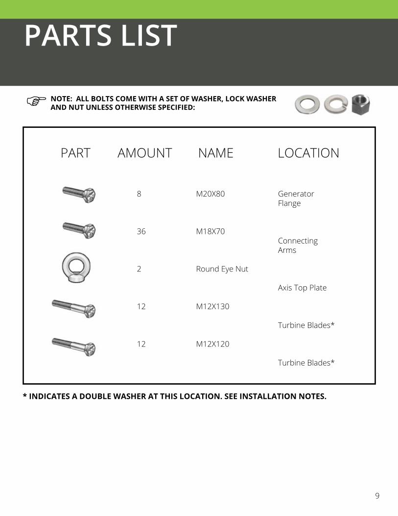
8
36
2
12
12
M20X80
M18X70
Round Eye Nut
M12X130
M12X120
Generator Flange
Connecting Arms
Axis Top Plate
Turbine Blades*
Turbine Blades*
PARTS LIST
NOTE: ALL BOLTS COME WITH A SET OF WASHER, LOCK WASHER AND NUT UNLESS OTHERWISE SPECIFIED:
9
PART AMOUNT NAME LOCATION
* INDICATES A DOUBLE WASHER AT THIS LOCATION. SEE INSTALLATION NOTES.

ELECTRICAL SYSTEM OVERVIEW
Detailed wiring diagrams are available from the UGE website or your UGE distributor.
WIRING DIAGRAMS
GRID-TIE
9 10

POSITIONING YOUR TURBINE
Selecting the optimal location for your VisionAIR5 turbine is crucial to capturing the wind power required to generate electricity. Several factors must be taken into account while selecting your location:
• Surrounding structures and other obstacles• Tower Height• Available Space• Zoning height restrictions
The taller the tower the higher quality the wind, however towers can be expensive so it is important to balance performance with cost to achieve the quickest payback. Ask UGE engineers for the minimum value of X and Y to have a good performance. It is also necessary to adhere to local building restrictions.
GETTING STARTED
11

TOWER AND SUPPORTING STRUCTURE
FOUNDATIONS:
Properly installing the tower and supporting structure for the turbine is essential to proper operation of your wind turbine.
UGE turbines can be roof mounted or be supported by a tower on a stand-alone foundation. Sample foundation drawings for reinforced concrete foundations are available from your UGE distributor. If required, UGE can also provide copies of these drawings that have been signed and sealed by a professional engineer. For projects that opt for a different foundation, the foundation should be designed by a professional engineer. Contact UGE technical support for foundation design criteria. Keep in mind that depending on local building code, concrete foundations can take up to 28 days to cure before the tower can be installed on it.
For projects that call for a roof mounted turbine, the interface between the tower and the building structure should be designed by a professional engineer. The loads going from the tower to the building are shown on the UGE load tables which are available through your UGE distributor. Contact UGE technical support if you or the engineer has any questions on this connection.
TOWERS:
Towers can be purchased through UGE or manufactured elsewhere. Towers not purchased through UGE shall be designed by a professional engineer. Contact UGE technical support for tower design criteria.
For projects using towers purchased through UGE, please see the “Tower Assembly Instructions” manual published by American Resource and Energy and which is available from your UGE distributor. This document explains the proper tower installation procedure as well as safety precautions to be taken when erecting the tower. Also see the tower design drawings for minimum slip overlaps between tower sections. We recommend measuring and marking these distances directly onto the outside face of the tower prior to tower installation to confirm adequate overlap of tower sections.
The tower shall be leveled after installed. Towers purchased through UGE are designed to be installed with a gap between the bottom plate of the tower and the top of the foundation or existing building. Leveling nuts placed in this gap allow for proper leveling of the tower during installation and during the annual maintenance check (see page 38). The tower shall be leveled such that the top plate of the tower is within 1 degree of horizontal.
GETTING STARTED
12

WIRE SIZING
The wire sizing directions listed in the ELECTRICAL SYSTEM OVERVIEW section are for SINGLE VisionAIR5 turbine installations. DO NOT attempt to use these wire sizing instructions for multiple VisionAIR5 turbines connected to a single controller or wind interface box. Please ensure all power is turned off before working on any electrical connections.
Wire gauge recommendations are based on NEC 310.16 for THHW copper wire below 100°F (A certified electrician shall verify wire gauge meets local electrical code). Wire length should not exceed 150m. Each electrical component shall have its own grounding wire and connect to a common earth ground. For projects where the turbine and tower are supported by a reinforced concrete foundation, the project electrician may opt to use the rebar in the foundation as the grounding electrode for the turbine and tower, per NEC article 694.40C.
USAGE
The VisionAIR5 is a wind powered three phase electricity generator. • It requires specialty electronics to convert the energy it creates into usable AC or DC. Please contact
UGE technical support if you are interested in using specialty electronics not purchased through UGE.• Do not modify the VisionAIR5
• Do not attempt to use a power source other than the wind to rotate the VisionAIR5
GETTING STARTED
13

ASSEMBLY REQUIREMENTS
Before proceeding to installation, the following tools will be needed to conduct safe and efficient assembly of the VisionAIR5 VAWT:
GETTING STARTED
1414
Torque wrench with 30 mm socket (M20 Bolt) & 27mm socket (M18 bolt) & 18mm socket (M12 Bolt)
30mm Adjustable Wrench
Hydraulic lift or crane
Silicone Sealant
Lifting Straps
Working Platform (see next page)
27mm (M18 bolt) crowfoot type wrench
Wrl
Wr2
Cr
Ss
Ls
Wp
Cf
1
1
1
1
1
1
1
TOOL ID AMOUNT NAME

Assembly of the VisionAIR5 requires a working platform capable of withstanding 756 kg (1665 lb) weight, with a 150mm (6”) diameter opening for the bottom nut of the generator to rest in; and approximately 5m x 5m x 10m (16’- 6” x 16’- 6” x 33’) space for assembly.
UGE turbines are available with several different mounting options. A crane is required for installing the tower and turbine. Choose a crane which can safely lift 756 kg (1665 lbs) of weight at least 6m (20’)above the height of your tower.
GETTING STARTED
15
3,393 mm [11’-2”]
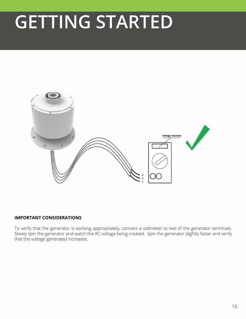
IMPORTANT CONSIDERATIONS
To verify that the generator is working appropriately, connect a voltmeter to two of the generator terminals. Slowly spin the generator and watch the AC voltage being created. Spin the generator slightly faster and verify that the voltage generated increases.
GETTING STARTED
16

SPIN DIRECTION
When uncertain of the orientation of the blades, along with corresponding upper and lower connecting arms, check with the diagram above to confirm that all parts are oriented to have the leading edge rotate in clockwise direction upon final assembly. The leading edge is the thicker edge of the blade.
GETTING STARTED
17
GETTING STARTED
18
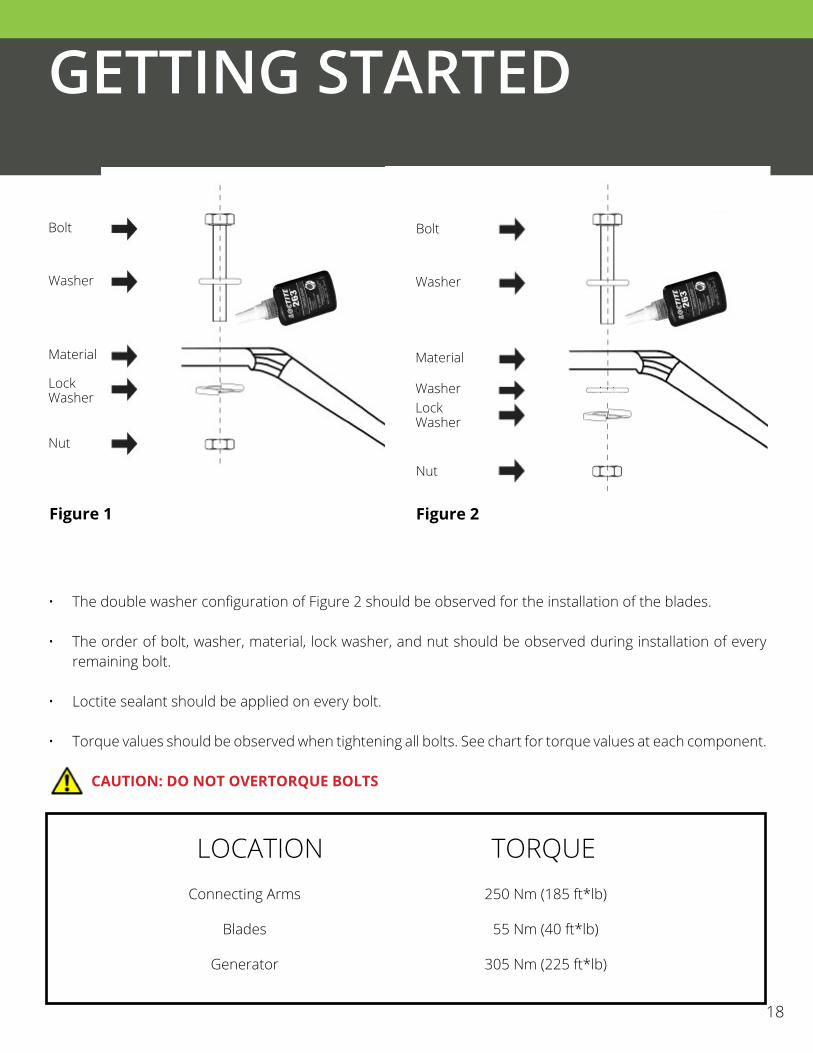
• The double washer configuration of Figure 2 should be observed for the installation of the blades.• • The order of bolt, washer, material, lock washer, and nut should be observed during installation of every
remaining bolt.
• Loctite sealant should be applied on every bolt.
• Torque values should be observed when tightening all bolts. See chart for torque values at each component. CAUTION: DO NOT OVERTORQUE BOLTS
Bolt Bolt
Washer Washer
Material Material
LockWasher
Nut
WasherLockWasher
Nut
250 Nm (185 ft*lb)
55 Nm (40 ft*lb)
305 Nm (225 ft*lb)
Figure 1 Figure 2
LOCATION TORQUEConnecting Arms
Blades
Generator

STEP 1
AXIS PREPARATION
Tool needed: Wr1
Screw the M18X70 bolts through the top flange of the generator axis and the top axis plate, and into the round eye nuts. Tighten the bolts onto the round eye nuts with two nuts to form an eyehook. This allows the crane to operate and lift the axis without damaging the shaft. These two eyehooks will remain in these locations until the end of assembly. When connecting the upper connecting arms (STEP 4, STEP 5), the eyehooks take the place of two M18X70 bolts. Use straps to connect eyehooks to crane and lift generator and axis onto assembly stand.
INSTALLATION
M18X70 X X2
Round Eye Nut X 2
20

20
STEP 2
ATTACH LOWER CONNECTING ARM
Tool needed: Wr1, Cf
Pair one connecting arm with two flange plate segments and place the connecting arm under the lower flange on the axis. Secure M18X70 bolts with washers and nuts.
NOTE: DIFFERENTIATE THE UPPER CONNECTING ARMS WITH THE LOWER CONNECTING ARMS USING IDENTIFYING STICKERS ATTACHED TO EACH ARM.
INSTALLATION
Bolt M18X70 X 6
21

COMPLETE LOWER CONNECTING ARM ASSEMBLY
Tool needed: Wr1, CfS
Slide one connecting arm in between the lower flange plates and mount the last flange plate segment. Secure with M18X70 bolts, washers and nuts. Continue to install the last connecting arm and also secure with M18X70 bolts, washers and nuts.
INSTALLATION
22
Bolt M18X70 X 12
STEP 3

STEP 4
ATTACH UPPER CONNECTING ARM
Tool needed: Wr1
Position the upper connecting arms between the two upper connection plate flanges. Secure in place with bolts M18X70. In this step, all bolts used are the same.NOTE: Eyehooks need to be removed in order to install the top connecting arms. Eyenuts may be reconnected to bolts after connecting arms are installed if needed to lift the turbine into place.
NOTE: DIFFERENTIATE THE UPPER CONNECTING ARMS WITH THE LOWER CONNECTING ARMS USING THE IDENTIFYING STICKERS ATTACHED TO EACH ARM.
INSTALLATION
23
Bolt M18X70 X 6
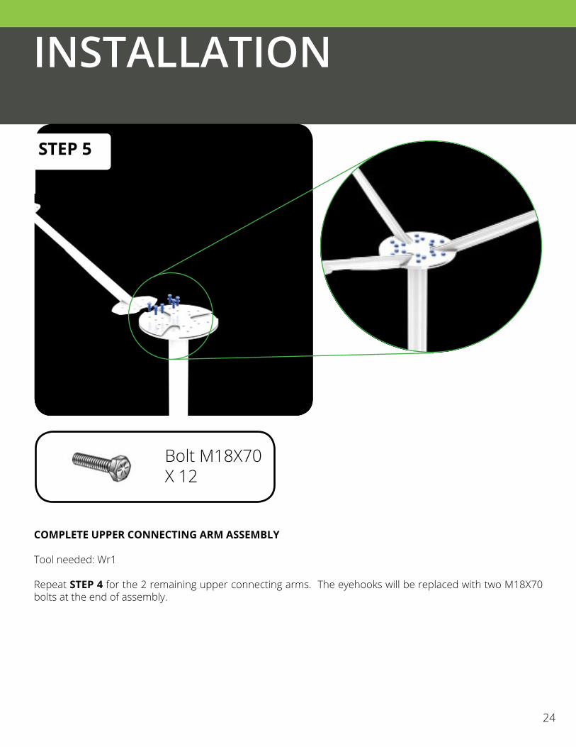
STEP 5
COMPLETE UPPER CONNECTING ARM ASSEMBLY
Tool needed: Wr1
Repeat STEP 4 for the 2 remaining upper connecting arms. The eyehooks will be replaced with two M18X70 bolts at the end of assembly.
INSTALLATION
24
Bolt M18X70 X 12

BLADE ASSEMBLYTools needed: Wr1, Ss
Use M12X130 and M12X120 bolts to position Turbine Blade adjacent to corresponding upper connecting arm and lower connecting arm. Use M12X130 and M12X120 bolts to fasten the blade to the connecting arms. M12X130 bolts are used for the leading edge, and M12X120 bolts for the trailing edge of the blade.
NOTE:
NOTE: IT IS OFTEN EASIER TO CONNECT THE BLADE TO THE TOP CONNECTING ARM FIRST, AND CONNECT TO THE LOWER CONNECTING ARM SECOND.
Bolt M12X120 X 4
Bolt M12X130 X 4
STEP 6
INSTALLATION
25
Leading Edge Trailing Edge
SEALANT SHOULD BE APPLIED TO GAPS BETWEEN BLADES AND CONNECTING ARMS AND AROUND ALL BOLT HEADS. SEALANT SHOULD BE APPLIED TO THE ARM FLANGE IN THE DEPICTED PATTERN.

INSTALLATION
STEP 7
COMPLETE BLADE ASSEMBLYTools needed: Wr1, Ss
Repeat STEP 6 for remaining 2 blades. With all blades installed, the turbine can now rotate freely without any resistance. This confirms that the turbine is ready for operation. CAUTION:
26
Bolt M12X120 X 8
Bolt M12X130 X 8
BEFORE PROCEEDING, RETURN TO ALL BOLTS AND ENSURE THAT THEY HAVE NOW BEEN TIGHTENED TO THE NECESSARY TORQUE REQUIREMENTS.

INSTALLATION
STEP 8
SHORT CIRCUIT GENERATOR
CAUTION:BEFORE INSTALLING THE TURBINE ON THE TOWER, THE GENERATOR WIRES MUST BE SHORT CIRCUITED TO PREVENT THE TURBINE FROM FREE SPINNING. THIS CAN BE DONE BY TYING THE STRIPPED ENDS OF THE GENERATOR WIRES TOGETHER.
NOTE: MAKE SURE YOU WRITE DOWN THE SERIAL NUMBER LISTED ON THE GENERATOR FOR THE WARRANTY BEFORE LIFTING IT UP ON THE TOWER.
27

INSTALLATION
STEP 9
TURBINE INSTALLATIONTool needed: Cr, Ls, Wr1Lift the wind turbine onto tower and mount onto supporting tower upper flange with bolts M20X80.
CAUTION:THE DOWN TOWER WIRES MUST BE SHORT CIRCUITED OR CONNECTED TO THE SAFETY BRAKE IN THE CLOSED POSITION. THE DOWN TOWER WIRES MUST BE SHORT CIRCUITED, CONNECTED TO THE SAFETY BRAKE IN THE CLOSED POSITION OR DIRECTLY TO THE WIND INTERFACE BOX.
28
CAUTION:DOWN TOWER WIRES SHALL BE SUPPORTED BY CABLE GRIPS AND HUNG FROM THE J HOOK IN THE TOWER TO PROVIDE STRAIN RELIEF. SEE THE UGE ELECTRICAL SUPPLEMENT FOR MORE INFORMATION.
Congratulations! You have completed the assembly of the VisionAIR5 Vertical Axis Wind Turbine unit. For the next steps of installation on how to connect your turbine to the Grid or your Battery Backup system, refer to the electronics installation manual.
Bolt M20X80X 8

COMMISSIONING CHECKLIST GRID-TIE
29
WITH THE SYSTEM PROPERLY WIRED PER THE SUPPLIED WIRING DIAGRAM, ENGAGE THE SAFETY BRAKE AND OPEN THE AC DISCONNECT SWITCHES #1 AND #2 BEFORE RUNNING THE FOLLOWING TESTS.
Safety Brake Switch (within Auto Safety Brake, if applicable) Confirm the resistance between each phase is 0ΩAC Disconnect Switch #1 (within Auto Safety Brake, if applicable) Confirm a switch is present between the turbine and wind interface box Confirm the switch rating meets or exceeds the recommended values as shown in the supplied wiring diagramAuto Safety Brake Confirm input and output wires are securely connected in their terminals Confirm no corrosion exists on any of the electrical parts within the unit’s enclosure Measure and record the voltage of the battery; conform the voltage reading is over 14VWind Interface Box Confirm model PVI-7200, GCB-5K or GCB-20KConfirm continuity across all three fuses inside the wind interface box (PVI-7200 only)Diversion Load Confirm the resistance of the diversion load is appropriate for the specific turbine: 30 – 250 Ω for VisionAIR3
Inverter Confirm model PVI 3.0, PVI 3.6 or GCI-5K for VisionAIR3
AC Disconnect #2 Confirm a switch is present between the inverter and the main panel Confirm the switch rating meets or exceeds the recommended valueGrounding Confirm the resistance between all grounding conductors is 0Ω WITH THE SYSTEM PROPERLY WIRED PER THE SUPPLIED WIRING DIAGRAM, CLOSE THE AC DISCONNECTS #1 AND #2 AND DISENGAGE THE SAFETY BRAKE
Safety Brake Switch & AC Disconnect #1 (within Auto Safety Brake, if applicable) Confirm a voltage exists between each phase with turbine spinning at the input terminals (if there is no wind present the turbine can be manually spun by hand to confirm voltage presence). Wind Interface Box Measure the voltage at the turbine input terminals. This value will vary based on turbine RPM (if there is no wind
present, the turbine can be manually spun by hand to confirm voltage presence).Inverter Confirm the inverter is powered on when connected to the grid (SeamlessGrid) or when the wind input is 50Vdc (Power-One). Confirm the inverter display shows no errors and successfully connects to the grid. For Power-One equipment, using the Aurora Installer software, confirm the correct MPPT is programmed to the inverter AND that the “Vin Start” input is set appropriately. See the UGE Partner Portal or your UGE distributor for a copy of the appropriate MPPT table. For SeamlessGrid, using the inverter manual as a reference, confirm the correct power curve is programmed into the inverter. See the UGE Partner Portal or your UGE distributor for a copy of the appropriate power curve.

OPERATION
31
Your UGE turbine is designed to operate with minimum action required on the part of the owner. If wired correctly, the controller or wind interface box / inverter combination will keep the turbine spinning at an optimum and safe RPM regardless of the wind speed. Please see the installation and/or owner’s manuals for the turbine’s electronics for more information on the proper operation of that equipment. Please follow the instructions below to ensure proper function of your wind turbine:
• Unless the safety brake is engaged, AC disconnect switch #1, the switch between the turbine and the controller must be in the closed (on or engaged) position. This switch should be locked in the closed position with a combination lock, key lock, or zip tie. Locking this switch is a requirement for the activation of the warranty. Leaving this switch in the open position with the safety brake not engaged can lead to a free-spinning situation, potentially damaging the turbine, and voiding the turbine’s warranty.
• The covers of all electronic components shall remain on those components unless maintenance is being performed on the turbine or electronics. These covers shall only be removed by qualified personnel such as a UGE distributor, licensed contractor, or certified electrician, or by an individual under the direct supervision of UGE technical staff
• The safety brake may be engaged and disengaged at the owner’s discretion. During times of high wind,the turbine may spin slowly even with the safety brake engaged. This is normal. If the turbine is rotating when the safety brake is engaged, the turbine should coast to a stop or very low RPM within 5 seconds. It is not recommended that the owner regularly engage the safety brake when the turbine is rotating quickly.
• If the tower was purchased with a hinge and manual or motorized raising system, the owner may raise and lower the tower at their discretion. The safety brake shall be engaged before raising or lowering the tower to prevent the turbine from spinning during the transition. It is recommended that the tower not be raised or lowered at times with wind speeds above 5 m/s [11mph]
• If the turbine appears to be spinning off balance or begins to emit a noticeable sound, engage the safety brake and contact UGE technical support at +1 (917) 720-5685 ext. 6 or at [email protected]
Does the VisionAIR5 need lightning protection?Lightning protection can be introduced to minimize the likelihood of high voltage and high current damage to the turbine and the control electronics. An ideal lightning protection solution is for any lightning strike to pass directly to ground without interfering with either the turbine control systems or entering into the building.
What happens if I lose power from my utility company?Any inverter supplied by UGE will have anti-islanding protection, meaning that the turbine will not be able to deliver current to the grid. This is a requirement to ensure the power lines can be repaired safely in the event of a fault.
When should I contact the service center?Contact your merchant if the turbine is making loud and unusual sounds and if the turbine is not spinning in response to strong persistent wind. Your distributor may contact the UGE service center, or recommend you contact us directly.
What should I do if I’m expecting a severe storm?The UGE VisionAIR5 is capable of lasting a severe storm, however if you have the opportunity it is advisable to turn on the safety brake and anchor the turbine with a rope or other physical anchor.
How do I shut down VisionAIR5?Engage the safety brake to stop the turbine from spinning
Can I leave the VisionAIR5 unattended?Yes, your turbine is able to operate without user feedback.
Can I mount VisionAIR5 to my roof?Structural considerations must be taken into account for your safety and the integrity of your building. It is also recommended a tower be installed to elevate the turbine above the level of the roof and where there is better quality wind.
Can I recycle my turbine?When the turbine has reached the end of its usable life it should be brought to a proper recycling center since the metal in the turbine and electronics can be reused.
1.
2.
3.
4.
5.
6.
7.
8.
FAQ
32

WARRANTY INFO
33
This Agreement (“Agreement”) is between you and UGE International and applies to UGE branded products (“Product”) and services purchased by you from UGE or any of its subsidiaries or affiliates, UGE authorized reseller or UGE authorized Partner (“Partner”), unless you enter into a separate written agreement with UGE. BY PURCHASING A UGE PRODUCT YOU AGREE THAT THIS AGREEMENT APPLIES TO YOU.
YOU MUST REGISTER THIS LIMITED WARRANTY AGREEMENT AND RECEIVE ACCEPTANCE BEFORE YOU TURN ON YOUR WIND TURBINE.
The term of this Limited Warranty is three (3) years (the “Limited Warranty Period”). For UGE vertical axis wind turbines;
Serial number____________________ Vertical axis wind turbine model type________________Assembly Date (From Generator Nameplate) ____________________Customer Name______________________________ Customer Phone Number______________________________ Customer Email______________________________ Turbine Installation Site Address________________________________________________________________
The Limited Warranty Period begins on the date of product installation. The installation must be performed by qualified personnel, such as a certified electrician, an employee of a licensed contractor or an employee of a UGE, this list is exemplary and by no means limiting. The date of installation shall occur in the 12 month period following the delivery date of the product to the Partner .The warranty must be registered within ten (10) business days from the date of installation. The unit should be installed but not turned on prior to registering the warranty. The warranty registration period will expire at midnight (local time of installation location) on the tenth (10th) day following the installation date. The expiration of the warranty registration period terminates all rights covered in this Limited Warranty Agreement.
Date of delivery to Partner (if applicable) ____________________ Date of installation_____________________
1. Registration of Limited Warranty.
i. Complete the online warranty registration form at http://www.ugei.com/warranty_form.php with the serial number, unit type, date of delivery to Partner date of installation, customer information and installation location.
ii. Submit End-Users Agreement Statement and dated by the End-User.
iii. Take the following photographs: -
UGE INTERNATIONAL THREE YEAR LIMITED WARRANTY AGREEMENT

WARRANTY INFO
34
Grid Tie Units - Assembled wind turbine - Wind interface box wiring - Inverter wiring - Diversion load wiring - Safety break and disconnect switch wiring (3x) - Locked AC disconnect switch #1. The switch shall be locked with a zip tie or other means of
ensuring the AC disconnect switch between the generator and the wind interface box cannot be opened accidentally. This photo is not required for sites using a double throw switch in lieu of a separate safety brake and AC disconnect switch #1, provided that the double throw switch has a label clearly stating the switch must not be left in the “O” (all open) position.
- Overall electrical assembly picture showing all components and conduits in between the electrical boxes.
iv. In the event the product is not installed using a tower supplied by UGE, you must submit professional technical design drawings of the tower and calculations of strength, deflection and vibrations. UGE will store this information on record. Please note that UGE will not review this information. For non-UGE supplied towers not installed with a standard foundation, you must submit drawings of any mounting provisions. For installations using UGE supplied towers but not our foundations, you must submit drawings of any mounting provisions. Please note that it is not the responsibility of UGE to review these drawings, and they will only be kept on record if needed for future troubleshooting.
UGE does not accept responsibility for damage to UGE manufactured products resulting from the use of non-UGE supplied towers, roof mounts or electronics. Please note that if you choose to use non-UGE supplied parts you should ensure that the towers are designed adequately for the loads the turbine will experience and that all other parts are suitable for the installation. v. Email the photographs and tower design, as applicable per iv. above, to [email protected].
vi. You will receive confirmation within two (2) business days of submitting the required images via email.
vii. Once you have received approval by way of a UGE Warranty Certificate you will not invalidate the warranty by turning your installed turbine on.
2. Maintenance. To qualify for the full Limited Warranty period, the product must undergo full maintenance once within the first month of installation and following the first full maintenance, once every 12 months. Product maintenance should be registered by downloading the maintenance form from the UGE website. The form should be filled in and submitted to [email protected]. The form should be submitted not more than 2 months from the date of installation and within ten (10) days from the date maintenance is performed. Then annually thereafter maintenance should be performed in no more than 13 month increments. All maintenance forms must be submitted in not more than ten (10) days following the date the maintenance is performed.
WARRANTY INFO
35
Annual maintenance must be performed until the life of the general or extended warranty has terminated. Please note that failure to submit annual maintenance reports will invalidate the warranty.
3. Product Limited Warranty. UGE warrants that its Products will be free from defects in materials and workmanship, under normal use for which it is intended, for the Limited Warranty Period. During the Limited Warranty Period, UGE may, at its option: (i) provide replacement parts necessary to repair the Product, (ii) repair the Product or replace it with a comparable product, or (iii) refund the amount you paid for the Product, less depreciation of ten percent (10%), upon its return, provided that UGE may, at its sole option, attempt to remediate any defects via technical support through telephone or electronic communication prior to taking any actions outlined in items (i) through (iii) listed above. It is hereby agreed and understood that UGE shall not be responsible for the installation of replacement parts or replacement products. Replacement parts and products shall be shipped to the original shipping address at no cost to you and shall be new or serviceably used, comparable in function and performance to the original part and warranted for the remainder of the Limited Warranty Period.
4. Warranty Limitations. This limited warranty does not cover misuse or minor imperfections in units that meet design specifications or imperfections that do not materially alter functionality. This limited warranty does not cover and UGE is not responsible for (1) damages caused by misuse, abuse, accidents, fire, acts of God, theft, disappearance, misplacement, power surges, viruses, reckless, willful, or intentional conduct, including, without limitation, damages caused by tampering with or dismantling any portion of the Product including its generator, (2) damages caused by servicing not authorized by UGE, (3) damages caused by usage that is not in accordance with Product instructions, (4) damages caused by failure to follow the Product instructions, (5) damages caused by the combination of Products with other non-UGE branded products, accessories, parts or components, (6) any equipment or components that were not included in your Product as originally sold to you, (7) normal wear and tear, (8) cosmetic damage that does not affect functionality or (9) damages or loss of function sustained as a result of wind speeds exceeding 55 m/s, lightening or hail or any other insurable loss under standard fire and extended coverage policies generally available for endorsement to you (10) re-configuration or re-connection of the electronics by a non-UGE authorized Partner, (11) units which have been disassembled and reinstalled shall only be covered by this warranty at the Supplier’s discretion, (12) units which have been turned on without approval, wherein approval is granted by way of a UGE Warranty Certificate corresponding to the unit serial number, (13) units which have been allowed to free spin by not being connected to an adequate load or safety break, (14) units which comprise second hand UGE parts, or UGE parts sold by anyone other than UGE. Note that if the turbine is installed first and not tied down or short-circuited while the electronics are being installed and the warranty is approved, the unit can still free spin and damage the blades, bearings and other parts. DAMAGE INCURRED DUE TO FREE SPINNING IS NOT COVERED BY THIS OR ANY OTHER WARRANTY(15)If a non-UGE authorized Partner configures, re-configures or re-connects the electronics for any UGE product this will automatically void the warranty on all components of the product; this includes the turbine.
5. Services and Service Limited Warranty. Any services provided to you by UGE that are not within the scope of the Limited Warranty also are governed by this Agreement. For a period of ninety (90) days after services are performed, UGE warrants that services provided by it were performed in a professional and workmanlike

WARRANTY INFO
36
manner. If your problem recurs within the 90 day service warranty period, UGE will, at its option, (1) re-perform the services, (2) replace the Product pursuant to the terms of this Agreement, or (3) permit you to return the Product and issue a refund pursuant to the terms of this Agreement. If you purchased an extended warranty, such as the UGE Extended Warranty Plan, please refer to the service plan for the coverage, duration and terms of service.
6. Instructions for Warranty Service. To obtain warranty service you must (1) notify UGE within ten (10) days of knowledge of any defect in Product, or any failure of the Product to function properly, (2) assist UGE in diagnosing issues with your Product and follow UGE’s warranty processes and (3) obtain warranty service from UGE or an authorized service provider specified by UGE. UGE will not reimburse you for service performed by others.
8. Limitation of Liability. THIS WARRANTY IS EXPRESSLY IN LIEU OF ANY OTHER AGREEMENTS, REPRESENTATIONS OR WARRANTIES, EXPRESS OR IMPLIED, INCLUDING ANY IMPLIED WARRANTY OF MERCHANTABILITY OR OF FITNESS FOR A PARTICULAR PURPOSE AND OF ANY OTHER OBLIGATIONS OR LIABILITY ON THE PART OF UGE. THE REMEDIES OF THE OWNER SET FORTH HEREIN ARE EXCLUSIVE. UGE NEITHER ASSUMES NOR AUTHORIZES ANY PERSON TO ASSUME FOR IT ANY OTHER OBLIGATION OR LIABILITY IN CONNECTION WITH THE SALE OF COVERED PRODUCTS. CORRECTION OF DEFECTS AND MALFUNCTIONS IN THE MANNER AND FOR THE APPLICABLE PERIOD ABOVE SHALL CONSTITUTE FULFILLMENT OF ALL RESPONSIBILITIES OF UGE. UGE SHALL NOT BE LIABLE FOR ANY INCIDENTAL OR CONSEQUENTIAL DAMAGES, SUCH AS BUT NOT LIMITED TO, LOSS OF PROFITS OR REVENUE, OTHER COMMERCIAL LOSSES, INCONVENIENCE OR COST OF REPLACEMENT EQUIPMENT. UGE’S MAXIMUM LIABILITY TO YOU IS LIMITED TO PURCHASE PRICE YOU PAID FOR PRODUCTS OR SERVICES PLUS INTEREST ALLOWED BY LAW. UGE IS NOT LIABLE TO YOU IF IT IS UNABLE TO PERFORM DUE TO EVENTS IT IS NOT ABLE TO CONTROL, SUCH AS ACTS OF GOD, PROPERTY DAMAGE, LOSS OF USE, INTERRUPTION OF BUSINESS, LOST PROFITS, LOST DATA OR OTHER CONSEQUENTIAL, PUNITIVE OR SPECIAL DAMAGES, HOWEVER CAUSED, WHETHER FOR BREACH OF WARRANTY, CONTRACT, TORT (INCLUDING NEGLIGENCE), STRICT LIABILITY OR OTHERWISE.
9. Dispute Resolution. If a dispute or claim is not resolved by you and UGE, the parties may agree to settle the dispute by mediation administered by (i) the American Arbitration Association (“AAA”) under its Commercial Mediation Procedures or (ii) for international matters, the International Centre for Dispute Resolution, a division of the AAA, in accordance with its International Mediation Procedures, before resorting to arbitration. The mediation shall be conducted using the English language for all purposes. Except with respect to preliminary equitable remedies provided herein or otherwise available at law, any controversy or claim relating to this Agreement not otherwise resolved between you and UGE through the previous provisions in this Agreement shall be settled through final and binding arbitration to be administered by the AAA according to its rules, or for international matters in accordance with its International Arbitration Rules. Such arbitration shall be held in New York, New York, and the proceedings and all pleadings, filings, written evidence, decisions and other relevant documents shall be in English. Any final decision issued in the arbitration shall be in writing, and binding and conclusive upon the parties to this Agreement and may be entered as a final judgment by any court of competent jurisdiction. Each Party shall bear its own costs in connection with the foregoing arbitration.

WARRANTY INFO
37
Except as may be required by law, neither party may disclose the existence, content or results of any mediation or arbitration hereunder, without the prior written consent of both parties. This agreement shall be governed by the laws of the state of New York, without regard to conflicts of laws rules.
10. General. UGE may assign this Agreement and/or any associated service plan without your consent and without notice to you. If UGE does assign this Agreement and/or any associated service plan, the assignee will assume all obligations to you, UGE will be released of all obligations, and you agree to look solely to the assignee for the performance of all obligations under this Agreement and/or any associated service plan. UGE and its subsidiaries and affiliates are intended beneficiaries of this Agreement. If there is any inconsistency between this Agreement and any other agreement included with or relating to Products or services purchased from UGE, this Agreement shall govern. This Agreement may not be modified, altered or amended without the written agreement of UGE. Any additional or altered terms shall be null and void, unless expressly agreed to in writing by UGE. If any term of this Agreement is illegal or unenforceable, the legality and enforceability of the remaining provisions shall not be affected or impaired.
11. Modifications. UGE reserves the right to change the terms of this Limited Warranty in the future. UGE reserves the right to make design changes, improvements and/or additions to its products without obligation to install such in products previously manufactured.
WARRANTY INFO MAINTENANCE AGREEMENT
38
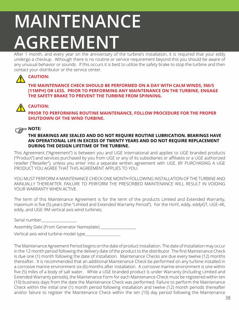
After 1 month, and every year on the anniversary of the turbine’s installation, it is required that your eddy undergo a checkup. Although there is no routine or service requirement beyond this you should be aware of any unusual behavior or sounds. If this occurs it is best to utilize the safety brake to stop the turbine and then contact your distributor or the service center. CAUTION:
THE MAINTENANCE CHECK SHOULD BE PERFORMED ON A DAY WITH CALM WINDS, 5M/S [11MPH] OR LESS. PRIOR TO PERFORMING ANY MAINTENANCE ON THE TURBINE, ENGAGE THE SAFETY BRAKE TO PREVENT THE TURBINE FROM SPINNING.
CAUTION:PRIOR TO PERFORMING ROUTINE MAINTENANCE, FOLLOW PROCEDURE FOR THE PROPER SHUTDOWN OF THE WIND TURBINE.
NOTE:THE BEARINGS ARE SEALED AND DO NOT REQUIRE ROUTINE LUBRICATION. BEARINGS HAVE AN OPERATIONAL LIFE IN EXCESS OF TWENTY YEARS AND DO NOT REQUIRE REPLACEMENT DURING THE DESIGN LIFETIME OF THE TURBINE.
This Agreement (“Agreement”) is between you and UGE International and applies to UGE branded products (“Product”) and services purchased by you from UGE or any of its subsidiaries or affiliates or a UGE authorized reseller (“Reseller”), unless you enter into a separate written agreement with UGE. BY PURCHASING A UGE PRODUCT YOU AGREE THAT THIS AGREEMENT APPLIES TO YOU.
YOU MUST PERFORM A MAINTENANCE CHECK ONE MONTH FOLLOWING INSTALLATION OF THE TURBINE AND ANNUALLY THEREAFTER. FAILURE TO PERFORM THE PRESCRIBED MAINTENANCE WILL RESULT IN VOIDING YOUR WARRANTY WHEN ACTIVE.
The term of this Maintenance Agreement is for the term of the products Limited and Extended Warranty, maximum is five (5) years (the “Limited and Extended Warranty Period”). For the HoYi!, eddy, eddyGT, UGE-4K, eddy, and UGE-9M vertical axis wind turbines; Serial number____________________ Assembly Date (From Generator Nameplate) ____________________Vertical axis wind turbine model type____________________
The Maintenance Agreement Period begins on the date of product installation. The date of installation may occur in the 12 month period following the delivery date of the product to the distributor. The first Maintenance Check is due one (1) month following the date of installation. Maintenance Checks are due every twelve (12) months thereafter. It is recommended that an additional Maintenance Check be performed on any turbine installed in a corrosive marine environment six (6) months after installation. A corrosive marine environment is one within five (5) miles of a body of salt water. While a UGE branded product is under Warranty (including Limited and Extended Warranty periods), the Maintenance Form for each Maintenance Check must be registered within ten (10) business days from the date the Maintenance Check was performed. Failure to perform the Maintenance Check within the initial one (1) month period following installation and twelve (12) month periods thereafter and/or failure to register the Maintenance Check within the ten (10) day period following the Maintenance

MAINTENANCE AGREEMENT
39
Check date, will invalidate the Limited and/or Extended Warranty. The expiration of the warranty registration period terminates all rights covered in this Maintenance Agreement.
Date of delivery to Distributor____________________Date of installation_____________________Date of Maintenance Check_____________________
1. Registration of Maintenance Check.
i. Maintenance must be performed by qualified personnel only (see section 4). ii. Fill in the serial number, vertical axis turbine model type, date of delivery to Distributor and date of
installation and date of Maintenance Check. iii. Initial next to each item in the table below once it has been checked:-
Item Passed (Y/N)
Checked By (Initials)
Blades are clean and free of dust or bug matter. Clean blades with soapy water or a non-bleach based household cleaning agent.Blades are free of defects.
Connecting arms are free of defects.
No abnormal noises from spinning turbine.
USER INSTALLED BOLTS: All bolts are still torqued to their minimum torque values. To check this, attempt to loosen the bolts with a torque wrench to a rating of ~5 Nm (~4 ft lb) less than the actual torque value of the bolted connection (make this value larger for the generator flange connection). If the wrench clicks and the bolt has not moved, the bolt and Loctite are still tight. If the bolt does move, you must remove the bolt fully, clean the existing Loctite, re-apply new Loctite and tighten the bolt back to its rated torque spec. A silicone sealant should be applied around the bolt head and washers after the bolt has been properly re-torqued.
FACTORY INSTALLED BOLTS: All horizontal bolts in the axis connections (just below the upper and lower flanges) are torqued to the following minimum torque values:eddy/VisionAIR3 - 80Nm [60ft*lb]UGE-4K/VisionAIR5 - 160Nm [120ft*lb]If any of these bolts are found loose, a silicone sealant with a tensile strength of greater than 700 kPa [100 psi] should be added around the bolt heads and washers after the bolt has been properly re-torqued.
Lower axis nut under the generator is flush, tight and cannot be loosened by hand.
Tower and metal components are free of rust or other visible defects.
Tower leveled such that the tower top flange is within 1 degree of horizontal.
Wind Regulator Box/Controller functional.
Check continuity of fuses in Wind Regulator Box/Controller if fuses present.

39
MAINTENANCE AGREEMENT
40
Item Passed (Y/N)
Checked By (Initials)
Auto Safety Brake functional and voltage reading of battery is over 14 volts.
Inverter functional and displays no error messages.
Resistance of diversion load recorded below.
Voltage produced when spinning turbine.
All wires securely attached to ports.
No rust exists on electrical connection points or inside enclosures.
Turbine, tower, and all electrical components are still properly grounded.
Batteries are within operable life.
Resistance of diversion load: _________________________Ω
iv. The person responsible for performing the Maintenance Check must sign and date below. v. Mail, fax or email the completed form to [email protected]. vi. You will receive confirmation, via email, within two (2) business days of submitting the Maintenance Check Form. vii. You will receive confirmation by way of an email.
2. Maintenance. To qualify for the full Limited Warranty period, the product must undergo full maintenance once within the first month of installation and following the first full maintenance, once every 12 months. Product maintenance should be registered by downloading the maintenance form from the UGE website. The form should be filled in and submitted to [email protected]. The form should be submitted not more than 2 months from the date of installation and within ten (10) days from the date maintenance is performed. Then annually thereafter maintenance should be performed in no more than 13-month increments. All maintenance forms must be submitted in not more than ten (10) days following the date the maintenance is performed. Annual maintenance must be performed until the life of the general or extended warranty has terminated. Please note that failure to submit annual maintenance reports will invalidate the warranty.
3. Grace Periods. The form should be submitted not more than 2 months from the date of installation and within ten (10) days from the date maintenance is performed. Then annually thereafter maintenance should be performed in no more than 13 month increments. All maintenance forms must be submitted in not more than ten (10) days following the date the maintenance is performed. Annual maintenance must be performed until the life of the general or extended warranty has terminated.
4. Maintenance Performance. The maintenance must be performed by qualified personnel, such as a certified electrician, an employee of a licensed contractor or an employee of an UGE distributor, this list is exemplary and by no means limiting.
5. Dispute Resolution. If a dispute or claim is not resolved by you and UGE, then it shall be finally settled by arbitration in accordance with the then current rules of arbitration of the American Arbitration Association. Such arbitration shall be held in New York, New York, and the proceedings and all pleadings, filings, written evidence, decisions and other relevant documents shall be in English. Any final decision issued in the arbitration shall be in writing, and binding and conclusive upon the parties to this Agreement and may be entered as a final judgment by any court of competent jurisdiction. Each Party shall bear its own costs in connection with the foregoing arbitration. This Agreement shall be governed by the laws of the state of New York, without regard to conflicts of laws rules.
6. General. UGE may assign this Agreement and/or any associated service plan without your consent and without notice to you. If UGE does assign this Agreement and/or any associated service plan, the assignee will assume all obligations to you, UGE will be released of all obligations, and you agree to look solely to the assignee for the performance of all obligations under this Agreement and/or any associated service plan. UGE and its subsidiaries and affiliates are intended beneficiaries of this Agreement. If there is any inconsistency between this Agreement and any other agreement included with or relating to Products or services purchased from UGE, this Agreement shall govern. This Agreement may not be modified, altered or amended without the written agreement of UGE. Any additional or altered terms shall be null and void, unless expressly agreed to in writing by UGE. If any term of this Agreement is illegal or unenforceable, the legality and enforceability of the remaining provisions shall not be affected or impaired.
7. Modifications. UGE reserves the right to change the terms of this Maintenance Form and Terms Agreement in the future. UGE reserves the right to make design changes, improvements and/or additions to its products without obligation to install such in products previously manufactured.
Name of Maintenance Performer:__________________________________________
Signature:_______________________________________
Position:________________________________________
Company:_______________________________________
NOTE: CONTACT UGE TECHNICAL SUPPORT IF ANY CHECKS DO NOT PASS.
MAINTENANCE AGREEMENT
41

41
GREEN BEST PRACTICES
42
Turbine InstallationOVERVIEW:
The purpose of this guide is to provide best practices for turbine and streetlight management with regards to sustainability. The tips provided in this guide are recommendations only. Please see the installation, operations and maintenance sections of the turbine, tower, and electrical component manuals for the respective system requirements. By completing as many of these best practices as possible, you can help ensure that your wind turbine/s is/are as sustainable an addition to your site as possible.
Below are some general themes recurrent throughout these best practices:
• Recycling, reuse, and sourcing recycled materials: Reusing materials, or using (or providing) recycled materials has several benefits. It can reduce natural resource strains (including water, minerals, and metal ores), decrease energy use and emissions associated with raw materials mining/harvesting and processing, and decrease waste by diverting materials from landfill. Note: Not all materials may be eligible for recycling pick-up in your area, and you may need to identify recycling centers or scrap metal sites at which to drop-off materials.
• Water management: To the extent possible, use recycled / greywater for purposes like mixing concrete for the foundation. Be efficient with water used to wash the site and turbine installation.
• Emissions reduction: Using manual construction techniques or alternatively powered construction vehicles can reduce greenhouse gas (GHG) emissions, which contribute to global climate change, and air pollutants. Furthermore, using recycled materials and looking for local reuse / recycling options where available lowers the GHG emissions associated with materials extraction, processing, and transportation.
• Protecting local habitats: Construction activities related to installation and decommissioning should work to minimize impacts on local ecosystems, being mindful not to disrupt local vegetation and water system as much as possible.
SHIPPING:
A best practice for managing shipping materials is to minimize the waste created from these materials. Depending on local recycling and waste-to-energy options, all packaging materials can be diverted from landfills. Landfilling waste presents multiple challenges, including methane production (a potent GHG) from decomposing organic waste, possible leakages of waste into water systems, and strain on land use as landfills’ capacities continue to be strained in many regions.
As a first step, reuse shipping materials as is possible, either yourself or through a local take-back program. This step maximizes their “useful life”. If reuse is not feasible, several elements of the packaging can be recycled or repurposed, depending on local recycling codes and facilities. Recycling/repurposing is a great next best option to reuse, as it reduces the waste to landfill and demands on natural resource inputs (e.g. energy, wood, etc.) by using the materials to create new products. A third option, pending local requirements and facilities

conditions, is to burn materials in waste-to-energy facilities. This process utilizes the energy value of the waste to produce electricity, thereby diverting waste from landfills and offsetting fossil fuels that may be otherwise used to produce electricity.
The following table summarizes some of the optimal disposal options for each material included in the shipping materials (options are ranked from most to least preferable). Note: your shipping materials may include: 1) foam and bubble wrap; or, 2) rubber sleeves and polyester wrapping. Please follow the best practices relevant to the specific materials included in your shipment.
Material Options
Bubble Wrap
• Reuse - Use again for future shipping needs; alternatively many local collection programs exist (e.g. at shipping stores and local government facilities)
• Recycling - Facilities that recycle bubble wrap are limited given the adhesives involved in keeping the plastic sheets together, however, some facilities may be available in your area
• Incineration - Burn at a waste-to-energy facility
Foam Padding/ Styrofoam Inserts
• Reuse - Use again for future shipping needs; alternatively many local collection program exist (e.g. at shipping stores and local government facilities)
• Recycling / Repurposing - Some organizations provide public drop-off locations and mail-back recycling programs for foam packaging (e.g. DART or EPS Industry Alliance)
• Incineration - Burn at a waste-to-energy facility
Crating Wood
• Reuse - Use wood for another shipment or on-site for an alternate purpose• Recycling / Repurposing - Many waste management companies will now take back
scrap wood for conversion into mulch, woodchips, particleboard, etc.• Incinerate - Burn at a waste-to-energy facility
Nails• Recycling - Ferrous scrap metal recycling facilities and some municipal recycling
programs will accept nails
Polyester Blade Wrap / Bags
• Recycling / Repurposing - Look for a local textile recycling center program, as a variety of commercial, public, and nonprofit programs exist (e.g. American Textile Recycling Services or Recycle with Clarity); the entities will repurpose or recycle the materials into items such as carpet pads, insulation, stuffing for toys or car seats, and fibers for new clothing
• Incineration - Burn at a waste-to-energy facility
GREEN BEST PRACTICES
43

GREEN BEST PRACTICES
43
Rubber Sleeves
• Recycling - Rubber recycling facilities (either municipal or private) are available in many areas
• Incineration - Burn at a waste-to-energy facility
INSTALLATION:
Foundation:There are four main best practices related to laying the foundation for your wind turbine/s during the installation phase:
• Use recycled aggregates and concrete to reduce mining impacts and landfill waste – Aggregate is coarse particulate material that is combined with cement to form a strong foundation for your turbine. Using recycled alternatives to these materials reduces both the amount of mined resources (and related impacts like land clearing, water pollution, sedimentation, noise / dust pollution, habitat loss, etc.) and also the amount of construction materials going into landfill. The use of recycled aggregate and/or concrete may contribute towards achieving credits under the Leadership in Energy & Environmental Design (LEED) green building rating system [relevant credits: Recycled Content credit (LEED v2009) or Building Product Disclosure and Optimization - Sourcing of Raw Materials credit (LEED v4)]. There are several options for recycled alternatives for the foundation, listed below. Refer to local building codes and/or American Concrete Institute (ACI) guidelines for maximum levels of the following alternatives that can be included in your foundation.
Option Description
Blast Furnace Slag (Cement Alternative)
• By-products of iron ore smelting• Lime is chemically combined with aluminates and silicates of ore and coke to
form a non- metallic product, then cooled to several different granularities• Used for different purposes, including aggregate and cement
Recycled Concrete Aggregate
• Crushed concrete and other materials that have been deemed ‘clean’ enough for reuse
• It is less dense and more porous than virgin aggregate• Minimizes concrete waste to landfill• Reduces aggregate mining• Lower carbon footprint• Generally cheaper than virgin aggregate
Recycled Fly / Flue Ash (Cement Alternative)
• A by-product of combustion of coal• The fine particles, containing many different trace elements, are captured by
electrostatic precipitators as they rise with the flue gases• Said to make the concrete flow and pump better• Results in a denser concrete because of the small particle size
GREEN BEST PRACTICES
44
• Use a rebar (reinforcement bar) made from recycled steel – Steel production is responsible for more than 3% of carbon dioxide emissions worldwide by some estimates and it takes four times as much energy to make steel from virgin ore than from recycled material. Each ton of steel creates almost two tons of carbon dioxide. Using recycled steel rebar lowers the carbon footprint of your project and saves steel from waste. In most cases rebar already has a high recycled content (up to 90%), however, check with your supplier to determine whether your rebar contains recycled content. As with recycled aggregates, use of recycled content in the rebar may contribute towards sustainable materials credits for the purposes of obtaining LEED certification.
• Use greywater / recycled water to produce concrete for the foundation – Refer to local building codes to determine whether use of non-potable water is acceptable in cement production in your area. When possible, use of greywater or recycled water for installation reduces the strain on hydrological systems and potable water resources. While greywater definitions can vary, it typically includes non-potable, used water from bathtubs / showers, sinks, and washing machines (per LEED definition). Non-potable water recovered from processes of concrete production can also be used to mix concrete. These processes include: (1) wash water from mixers or that was a part of a concrete mixture, (2) water collected in a basin as a result of storm water runoff at a concrete production facility, or (3) other water that contains quantities of concrete ingredients. Refer to local building codes for the local definition/requirements for non-potable/greywater water.
• Minimize runoff: Hardscapes (like the cement foundation) increase water runoff during precipitation events, which can increase sedimentation and contaminant levels (like pathogens, chemicals, debris, and excess nutrients) in local waterways. Use strategies like planting low-lying vegetation near the hardscape or using permeable pavers in other locations on the site to offset the introduction of cement for the turbine. Use as small a foundation as is structurally necessary.
General / Site Considerations:
There are several steps you can take to minimize overall environmental impact associated with installing your wind turbine/s:
• Reduce air pollutant emissions: Traditional construction equipment used to level the site and install the turbine/s (e.g. cranes, bulldozers, etc.) can emit air pollutants. You can reduce the pollutant emissions associated with equipment use by reducing or eliminating idling or by using equipment with cleaner / lower-emitting equipment (e.g. Ultra-Low Sulfur Diesel, propane / LNG, hybrid- / electric, biodiesel). To the extent that installation and decommissioning can be done manually, doing so will help to reduce pollutant emissions associated with equipment use. Thus, we recommend manual installation for all elements that can be done so safely and effectively.
• Reduce / offset greenhouse (GHG) emissions: Construction equipment also may emit GHGs from the combustion of fossil fuels. Idling reductions will also reduce GHG emissions, as will using low-emitting / alternative equipment, such as propane / LNG, biodiesel, or hybrid-/electric models (Note: net emissions
GREEN BEST PRACTICES
45

45
may only lower for hybrid-/electric vehicles if the electricity source has a lower emissions profile than traditional fuels, like diesel). To the extent that installation can be done manually, doing so will help to reduce GHG emissions associated with equipment use. Thus, we recommend manual installation for all elements that can be done so safely and effectively. Additionally, try to plant new trees in place of any trees cleared to install the turbine/s to continue to have this natural carbon sink on site (although make sure to plant in locations that will not interfere with the performance of your turbine). You may also explore purchasing carbon-offsets to reduce net GHG emissions from your project, although we recommend this as a next-best alternative after pure GHG emissions reduction.
• Preserve local ecosystems: We recommend minimizing impacts to local ecosystems as much as possible to support biodiversity and ecosystem services. Consider impacts to local hydrology (e.g. streamflows), vegetation (e.g. types and number of plantings), and habitats as much as possible when installing your wind turbine/s.
MAINTENANCE:Towers:
Hot-dip galvanized steel towers should be well maintained to ensure their longevity for the turbine / streetlight installation and potential future reuse after the lives of the renewable energy components have ended. Tower reuse helps to avoid the environmental impacts of manufacturing new towers for future systems, which may include greenhouse gas emissions, mining impacts (noise / dust pollution, habitat loss, sedimentation, etc.), water use, and more. A few methods for maintaining your tower are:
• Remove any discoloration or corrosion as soon as possible to avoid permanent discoloration and pitting of the surface.
• Store uninstalled towers in dry and well ventilated areas, and ensure that they have minimal contact with other metals.
• Remove any surface contaminants using clean cloths and non-abrasive cleaners; don’t allow water to drip continuously on steel and don’t clean the towers with corrosive cleaning products or metal scrubbers.
• Consult the tower manufacturer for more information on tower maintenance and warranty information.
Turbines:
Proper maintenance maximizes the lifespan of the turbines, thereby reducing waste from premature turbine disposal and energy / materials requirements of creating new turbines to replace damaged and prematurely decommissioned turbines. Refer to the maintenance section of the Owner’s Manual for additional details/requirements for turbine maintenance and warranty.
GREEN BEST PRACTICES
46

DECOMMISSIONING:
General / Site Considerations:See: “INSTALLATION: General / Site Considerations” for guidance. Similar principles should be applied when using machinery and altering the landscape during the decommissioning phase.
Materials Management:
At the end of the wind turbine’s life, consider opportunities to reuse or recycle some or all components of the system, including the foundation, tower, and turbine parts. Consider each component individually as something that can be broken apart from the system and be reused, recycled or disposed of in a nearby waste incinerator or (as a last result) a landfill.
• Reuse / Resale / Refurbishment: Some of the materials in the turbine can be used as-is or refurbished for further use. Options for resale and refurbishment may vary by area, so these suggestions are meant to serve as a starting point that can be tailored based on availability.
• Recycling / Material Recovery: Options will also vary from region to region. However, there are several common options for recycling many of the turbine parts, especially the various metal components.
• Incineration: If disposal is chosen, incineration is a good option to capture the energy value of the turbine for electricity production (assuming it is done at a waste-to-energy facility).
Below is a summary table of end-of-life options for elements of the turbine system (options ranked in order from most to least preferable where multiple options are listed):
Component End-of-Life OptionsGenerator • Recycling / Recovery - Scrap metal recycling is the best option given the difficulty of
breaking this element into its component materials on-site; scrap metal recyclers will recover the relevant metals and likely dispose of the remaining materials in an incinerator or hazardous waste disposal site
Axis • Recycling / Recovery - Ferrous scrap metal recycling
GREEN BEST PRACTICES
47

Blades • Reuse / Resale - Possible sale to off-taker for refurbishment / reuse• Recycling / Recovery - Some companies [e.g. Seawolf Design (FL, USA) and ReFibre Aps
(Denmark)] process wind turbine blades (via mechanical recycling or pyrolysis) to produce recyclates that are used in applications like fiberboard or asphalt, or polymers used in products like glue.
• Incineration - Turbine blades can also be incinerated (e.g. at a combined heat and power plant) to generate electricity; the remaining ash from the incineration process (~60% of material) can be used as an input in other materials, such as cement, paint, and glue; however, recycling is a better option where available, due to the relatively low heat value of turbine blades and the potential for incineration of the inorganic materials to release hazardous flue gases
Tower • Reuse - For another small-scale renewable energy solution, as a streetlight, as a flagpole, etc. (longer life than wind turbine)
• Recycling / Recovery - Ferrous scrap metal recycling
Batteries • Reuse / Resale• Recycling / Recovery - Various companies across the world provide battery recycling
solutions to separate recoverable materials from hazardous ones; some local recycling facilities may also serve as a collection point for batteries
Foundation: Concrete
• Reuse - Use the foundation for an alternate purpose once the turbine has been taken down (e.g. use in conjunction with tower as a flagpole)
• Recycling / Recovery - Break up the concrete and provide to a concrete recycling company for creation of recycled aggregate
Foundation: Rebar
• Reuse - Use the foundation for an alternate purpose (e.g. use in conjunction with the tower as a flagpole); if the concrete is broken up, the rebar can be reused independently
• Recycling / Recovery - If the concrete is broken up, the rebar can also be recovered for ferrous scrap metal recycling
GREEN BEST PRACTICES
48

RECYCLING SOURCES:
Below, we have provided a list of some good tools for finding recycling / recovery centers and ship-back programs near you. Note: This list is not intended to be exhaustive and we recommend that you do a search of nearby programs and businesses if you do not see a relevant resource in the list below.
• 1-800-RECYCLING.com (http://1800recycling.com/) - US• Call 2 Recycle (http://www.call2recycle.org/4-simple-steps-to-recycling/) - US• DART (https://www.dart.biz/web/environ.nsf/pages/drop-off.html) - US• EPS Industry Alliance (http://www.epspackaging.org/index.php?option=com_content&view=article&id=8
&Itemid=4) - US• American Textile Recycling Services (http://atrscorp.com/contact/) - US• Earth 911 (http://earth911.com/) - US• Recycler Finder (http://www.recyclerfinder.com/) - US• Directgov (http://local.direct.gov.uk/LDGRedirect/index.jsp?LGSL=534&LGIL=8) - UK• Recycle with Clarity (http://recyclewithclarity.com/find-a-recycling-site.php) - UK• Waste Connect (http://www.wasteconnect.co.uk/default.aspx) - UK• RecyclingNearYou (http://recyclingnearyou.com.au/) - Australia• Recycling Marketplace (http://www.recycle.net/) - Regional sites for US / Canada, Europe, Asia, Pacific
Region, Africa, and South America• Sims Metal Management (http://www.simsmm.com/Local-Solutions/AllLocations) - Locations in Australia,
Canada, Hong Kong, New Zealand, Papua New Guinea, Singapore, South Africa, UK and US
The Best Practices Guide on pages 42 to 49 of this document has been prepared in good faith on the basis of information available at the date of publication without any independent verification. The information is intended to be a guideline only and should not be construed as professional advice from UGE International. UGE International does not guarantee or warrant the accuracy, reliability, completeness or currency of the information in this publication nor its usefulness in achieving any purpose. Readers are responsible for assessing the relevance and accuracy of the content of this publication. UGE International will not be liable for any loss, damage, cost or expense incurred or arising by reason of any person using or relying on information in this publication.
GREEN BEST PRACTICES
49

49
NOTES
50

TECHNICAL SUPPORT
If your product requires troubleshooting or warranty service, contact your merchant. If you are unable to contact your merchant, or the merchant is unable to provide service, contact UGE directly at:
UGE International330 West 38th StreetSuite 1103New York, NY 10018
Tech. Support Phone: +1 (917) 720-5685Email: [email protected]
June 2016Copyright UGE International, Ltd. 2016
This equipment complies with all the fundamental requirements of the relevant standards and guidelines. All associated documents and the original Declaration of Conformity are available from the manufacturer.