OWNERS MANUAL - Link OWNERS MANUAL ULTRARIDE AIR CONTROL KIT (Link Part Nos. 800M0046 & 800M0050)...
22
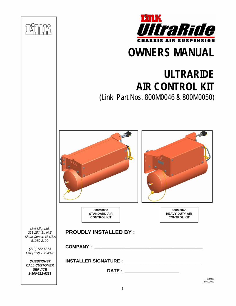
1 OWNERS MANUAL ULTRARIDE AIR CONTROL KIT (Link Part Nos. 800M0046 & 800M0050) Link Mfg. Ltd. 223 15th St. N.E. Sioux Center, IA USA 51250-2120 (712) 722-4874 Fax (712) 722-4876 QUESTIONS? CALL CUSTOMER SERVICE 1-800-222-6283 050919 80001092 PROUDLY INSTALLED BY : COMPANY : __________________________________________ INSTALLER SIGNATURE : ______________________________ DATE : _____________________ 800M0050 STANDARD AIR CONTROL KIT 800M0046 HEAVY DUTY AIR CONTROL KIT
Transcript of OWNERS MANUAL - Link OWNERS MANUAL ULTRARIDE AIR CONTROL KIT (Link Part Nos. 800M0046 & 800M0050)...
1
OWNERS MANUAL
ULTRARIDE AIR CONTROL KIT
(Link Part Nos. 800M0046 & 800M0050)
Link Mfg. Ltd. 223 15th St. N.E.
Sioux Center, IA USA 51250-2120
(712) 722-4874 Fax (712) 722-4876
QUESTIONS? CALL CUSTOMER
SERVICE 1-800-222-6283
050919 80001092
PROUDLY INSTALLED BY : COMPANY : __________________________________________ INSTALLER SIGNATURE : ______________________________ DATE : _____________________
800M0050 STANDARD AIR CONTROL KIT
800M0046 HEAVY DUTY AIR
CONTROL KIT
2
INSTALLATION INSTRUCTIONS INDEX 1.0 INTRODUCTION 2.0 MOUNTING THE AIR SYTEM 3.0 ELECTRICAL SYSTEM 4.0 AIR SYSTEM OPERATION 5.0 SERVICE & MAINTENANCE APPENDIX A WIRING DETAIL FOR F-SERIES FORD VEHICLES APPENDIX B WIRING DETAIL FOR GMC VEHICLES
3
1. INTRODUCTION IMPORTANT! It is important that the entire installation instructions be read thoroughly before proceeding with the installation.
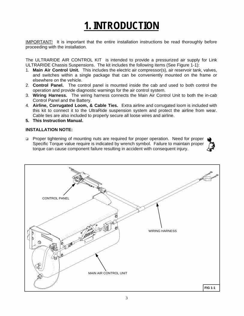
The ULTRARIDE AIR CONTROL KIT is intended to provide a pressurized air supply for Link ULTRARIDE Chassis Suspensions. The kit includes the following items (See Figure 1-1): 1. Main Air Control Unit. This includes the electric air compressor(s), air reservoir tank, valves,
and switches within a single package that can be conveniently mounted on the frame or elsewhere on the vehicle.
2. Control Panel. The control panel is mounted inside the cab and used to both control the operation and provide diagnostic warnings for the air control system.
3. Wiring Harness. The wiring harness connects the Main Air Control Unit to both the in-cab Control Panel and the Battery.
4. Airline, Corrugated Loom, & Cable Ties. Extra airline and corrugated loom is included with this kit to connect it to the UltraRide suspension system and protect the airline from wear. Cable ties are also included to properly secure all loose wires and airline.
5. This Instruction Manual.
INSTALLATION NOTE:
Proper tightening of mounting nuts are required for proper operation. Need for proper Specific Torque value require is indicated by wrench symbol. Failure to maintain proper torque can cause component failure resulting in accident with consequent injury.
MAIN AIR CONTROL UNIT
CONTROL PANEL
WIRING HARNESS
FIG 1-1
4
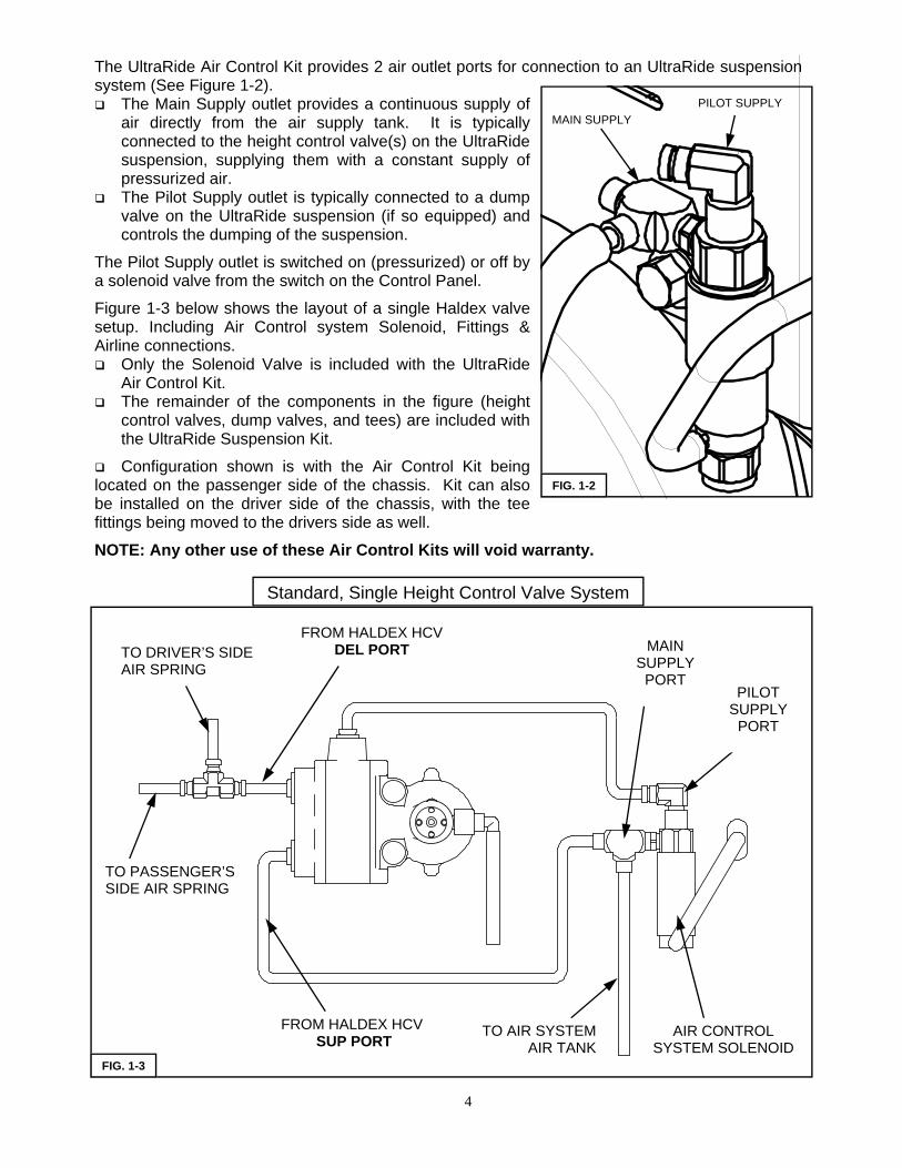
The UltraRide Air Control Kit provides 2 air outlet ports for connection to an UltraRide suspension system (See Figure 1-2). The Main Supply outlet provides a continuous supply of
air directly from the air supply tank. It is typically connected to the height control valve(s) on the UltraRide suspension, supplying them with a constant supply of pressurized air.
The Pilot Supply outlet is typically connected to a dump valve on the UltraRide suspension (if so equipped) and controls the dumping of the suspension.
The Pilot Supply outlet is switched on (pressurized) or off by a solenoid valve from the switch on the Control Panel.
Figure 1-3 below shows the layout of a single Haldex valve setup. Including Air Control system Solenoid, Fittings & Airline connections. Only the Solenoid Valve is included with the UltraRide
Air Control Kit. The remainder of the components in the figure (height
control valves, dump valves, and tees) are included with the UltraRide Suspension Kit.
Configuration shown is with the Air Control Kit being located on the passenger side of the chassis. Kit can also be installed on the driver side of the chassis, with the tee fittings being moved to the drivers side as well. NOTE: Any other use of these Air Control Kits will void warranty.
MAIN SUPPLY PILOT SUPPLY
FIG. 1-2
Standard, Single Height Control Valve System
TO PASSENGER’S SIDE AIR SPRING
FROM HALDEX HCV SUP PORT
TO AIR SYSTEM AIR TANK
AIR CONTROL SYSTEM SOLENOID
FROM HALDEX HCV DEL PORT TO DRIVER’S SIDE
AIR SPRING PILOT
SUPPLY PORT
MAIN SUPPLY
PORT
FIG. 1-3
5
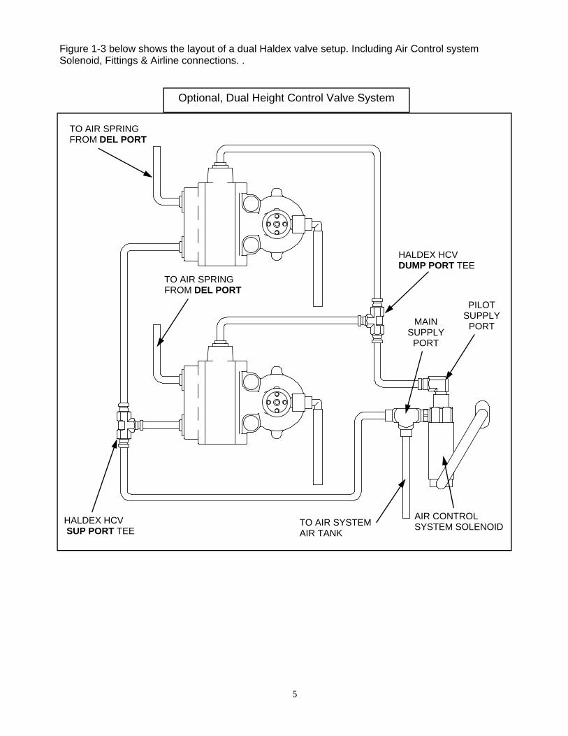
Optional, Dual Height Control Valve System
TO AIR SPRING FROM DEL PORT
HALDEX HCV SUP PORT TEE
TO AIR SYSTEM AIR TANK
AIR CONTROL SYSTEM SOLENOID
HALDEX HCV DUMP PORT TEE
TO AIR SPRING FROM DEL PORT
PILOT SUPPLY
PORT MAIN SUPPLY
PORT
Figure 1-3 below shows the layout of a dual Haldex valve setup. Including Air Control system Solenoid, Fittings & Airline connections. .

6
2. MOUNTING THE AIR SYSTEM
Installation Notes :
If your vehicle has a frame body that does not allow the air control system box to be located as shown, you will need to determine another location for mounting and possibly drill the neces-sary holes.
If installing on the frame underneath the cab, make sure it is mounted as high on the frame as possible to allow for ground clearance below the tank.
Adapter brackets may be available to mount the Air Control Unit inside the frame rails or using a different bolt hole pattern. Please contact your Link sales representative for availability of Link Part no. 800M0053.
1. Mount the Air Control Box to the side of the frame in the specified location. See Figure 2-1. Use (4) 5/16 X 1 3/4 UNC FLANGE BOLTS , (4) 5/16 UNC TOPLOCK FLANGE NUTS, and (4) 5/16 WASHERS (ALL SUPPLIED) to fasten the Air Control Box to the frame, placing the Rub-ber Isolators between the box and frame. (Torque to 15-20 FT-LBS.) Some drilling may be re-quired for this procedure. Do not tighten the fasteners so tight that back of the Air Control Box contacts any bolts protruding from the frame. See Figure 2-1 for details.
NOTE FOR 800M0046 AIR SYSTEM INSTALLATION: The compressor filter system is de-signed to allow for improved accessibility for maintenance considerations. Please use the fit-tings and airline supplied to mount the filter either in a body compartment or other vehicle chas-sis area that will provide a clean air environment. If no other option is suitable, the filter can still be mounted directly to the compressor head. DO NOT mount the filter directly to the chassis undercarriage, where it is exposed to dust and debris. Please consult the customer when in-stalling to determine the appropriate location.
FIG. 2-1

7
3. ELECTRICAL SYSTEM
1. Attach the Wiring Harness to the Air Control Box using supplied clips and route along frame to the battery. Do not connect wires to battery at this point. See Figure 3-1 for details. Note: The battery wire leads contain a 50A self-resetting circuit breaker in it.
2. Route the wiring harness branch into the cab (electrical loom with white electrical connector). This can be accomplished by properly routing the harness to the driver side of the bulkhead and either passing through an existing grommeted hole behind the dash, or drilling an appropriate hole in the bulkhead to pass the harness through. NOTE: use a grommet around the harness and in the bulkhead; this reduces noise transmission and keeps the harness away from the sharp edge of the bulkhead. For other wire harness routing options, see Appendix A for Ford vehicles or Appendix B for GMC vehicles.
FIG. 3-1 DRAIN RELEASE CABLE
DUMP VALVE SOLENOID
TO BATTERY
TO CONTROL PANEL IN CAB
CONTROL PANEL
CAUTION! All wiring should be routed and secured neatly to avoid any functional or visual issues. Under hood and under-body wire routings should be clear of sharp edges (3/4 inches minimum) and direct sources of
heat (4 inches minimum). Wiring located in the passenger compartment should be routed away from high temperature areas over the muffler. Wiring should not be routed through wheel well areas where it may be damaged by tire or road debris, and it should not be routed over the exhaust system. Wiring should not contact the brake lines or fuel lines. Disconnect the battery cables before servicing any electri-cal components.

8
FIG. 3-2
DO NOT INSTALL COMPONENTS IN THE SHADED “PASSENGER PROTECTION” AREAS
3. Mount the supplied control panel under the dash somewhere between the driver and passenger seating areas; this will keep it out of the Passenger Protection Zone. See shaded areas of Fig-ure 3-2.
4. Connect the harness to the Control Panel pigtail.
5. The white wire included with the Control Panel must be connected to a “key hot” signal wire so that it only receives +12V power when the ignition key is in the “RUN” position. This will ensure that the Air Control Kit is only active when the key is on and prevents the batteries from drain-ing. After locating a suitable “key hot” wire, connect it to the white control panel wire by pushing each wire into the ends of the solder butt joint and heating up until the tubing is clamped around the wire covering and the solder has melted to join the two wires. For details on locating a suit-able “key hot” wire for your application, see Appendix A for Ford vehicles or Appendix B for GMC vehicles.
6. Connect the battery harness to the positive and negative sides of the battery by placing ring terminals over the battery terminal bolt and securing in place with the existing nut. (Red wire to positive, Black wire to negative side.) Route and tie the wire harness along the battery cable to provide a cleaner wire routing and assist battery serviceability.
7. Use supplied cable ties to secure wires and to keep them away from all hazardous objects, this is especially important in the engine compartment. Use rubber grommets anywhere wires are to be run through sheet metal panels. Also make sure the wire harness is secured such as not to allow contact with any heat sources (e.g. exhaust).

9
4. AIR SYSTEM OPERATION
NOTE: Before operating the Air Control Kit, be sure it has been properly connected to the UltraRide Chassis Suspension. Make sure both switches on the Air Kit control panel are OFF.
1. Using a shop air supply, fill the air tank using the schraeder valve to a pressure of 80-100 psi. This helps keep air compressor run-time to a minimum when the tank is empty.
2. Turn the ignition key to the “RUN” position. (You may wish to actually start the vehicle, as this will prevent draining the batteries while operating the air control kit.)
3. Switch the Compressor switch to ON. The compressor(s) in the air control kit should turn on, pressurizing the air tank. After a few minutes, the air compressor(s) will automatically turn off when the air tank reaches full pressure. Using a soapy water solution check the air tank, air lines, and any connections for leaks.
4. Check the Dump function by switching the Dump switch to ON. The suspension will immedi-ately begin to exhaust air from the air springs and begin to drop. With the dump switch ON, the air tank should not loose any pressure and the compressor(s) should NOT engage.
5. Turn the Dump switch OFF. The suspension should immediately begin to fill the air springs and then begin to lift. The compressors may engage to replenish the lost pressure in the air tank.
NOTE: The Low Pressure warning light may come on briefly when airing the suspension up again after dumping it. This is normal and requires attention only if the low pressure warning light re-mains on for extended periods of time.
FIG. 4-1
10
5. SERVICE & MAINTENANCE
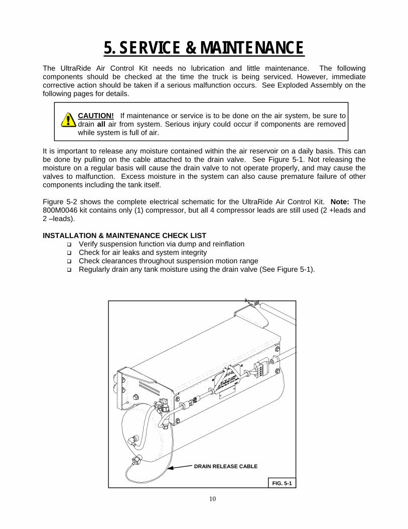
The UltraRide Air Control Kit needs no lubrication and little maintenance. The following components should be checked at the time the truck is being serviced. However, immediate corrective action should be taken if a serious malfunction occurs. See Exploded Assembly on the following pages for details.
It is important to release any moisture contained within the air reservoir on a daily basis. This can be done by pulling on the cable attached to the drain valve. See Figure 5-1. Not releasing the moisture on a regular basis will cause the drain valve to not operate properly, and may cause the valves to malfunction. Excess moisture in the system can also cause premature failure of other components including the tank itself. Figure 5-2 shows the complete electrical schematic for the UltraRide Air Control Kit. Note: The 800M0046 kit contains only (1) compressor, but all 4 compressor leads are still used (2 +leads and 2 –leads). INSTALLATION & MAINTENANCE CHECK LIST
Verify suspension function via dump and reinflation Check for air leaks and system integrity Check clearances throughout suspension motion range Regularly drain any tank moisture using the drain valve (See Figure 5-1).
CAUTION! If maintenance or service is to be done on the air system, be sure to drain all air from system. Serious injury could occur if components are removed while system is full of air.
FIG. 5-1
DRAIN RELEASE CABLE

11
FIG. 5-2
AIR CONTROL KIT ELECTRICAL SCHEMATIC
12
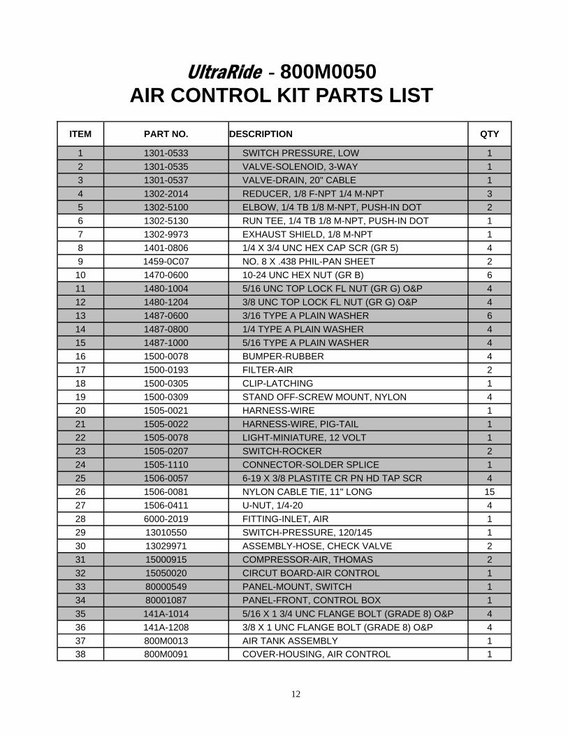
UltraRide - 800M0050 AIR CONTROL KIT PARTS LIST
ITEM PART NO. DESCRIPTION QTY
1 1301-0533 SWITCH PRESSURE, LOW 1 2 1301-0535 VALVE-SOLENOID, 3-WAY 1 3 1301-0537 VALVE-DRAIN, 20" CABLE 1 4 1302-2014 REDUCER, 1/8 F-NPT 1/4 M-NPT 3 5 1302-5100 ELBOW, 1/4 TB 1/8 M-NPT, PUSH-IN DOT 2 6 1302-5130 RUN TEE, 1/4 TB 1/8 M-NPT, PUSH-IN DOT 1 7 1302-9973 EXHAUST SHIELD, 1/8 M-NPT 1 8 1401-0806 1/4 X 3/4 UNC HEX CAP SCR (GR 5) 4 9 1459-0C07 NO. 8 X .438 PHIL-PAN SHEET 2 10 1470-0600 10-24 UNC HEX NUT (GR B) 6 11 1480-1004 5/16 UNC TOP LOCK FL NUT (GR G) O&P 4 12 1480-1204 3/8 UNC TOP LOCK FL NUT (GR G) O&P 4 13 1487-0600 3/16 TYPE A PLAIN WASHER 6 14 1487-0800 1/4 TYPE A PLAIN WASHER 4 15 1487-1000 5/16 TYPE A PLAIN WASHER 4 16 1500-0078 BUMPER-RUBBER 4 17 1500-0193 FILTER-AIR 2 18 1500-0305 CLIP-LATCHING 1 19 1500-0309 STAND OFF-SCREW MOUNT, NYLON 4 20 1505-0021 HARNESS-WIRE 1 21 1505-0022 HARNESS-WIRE, PIG-TAIL 1 22 1505-0078 LIGHT-MINIATURE, 12 VOLT 1 23 1505-0207 SWITCH-ROCKER 2 24 1505-1110 CONNECTOR-SOLDER SPLICE 1 25 1506-0057 6-19 X 3/8 PLASTITE CR PN HD TAP SCR 4 26 1506-0081 NYLON CABLE TIE, 11" LONG 15 27 1506-0411 U-NUT, 1/4-20 4 28 6000-2019 FITTING-INLET, AIR 1 29 13010550 SWITCH-PRESSURE, 120/145 1 30 13029971 ASSEMBLY-HOSE, CHECK VALVE 2 31 15000915 COMPRESSOR-AIR, THOMAS 2 32 15050020 CIRCUT BOARD-AIR CONTROL 1 33 80000549 PANEL-MOUNT, SWITCH 1 34 80001087 PANEL-FRONT, CONTROL BOX 1 35 141A-1014 5/16 X 1 3/4 UNC FLANGE BOLT (GRADE 8) O&P 4 36 141A-1208 3/8 X 1 UNC FLANGE BOLT (GRADE 8) O&P 4 37 800M0013 AIR TANK ASSEMBLY 1 38 800M0091 COVER-HOUSING, AIR CONTROL 1

13
UltraRide - 800M0050 AIR CONTROL KIT
14
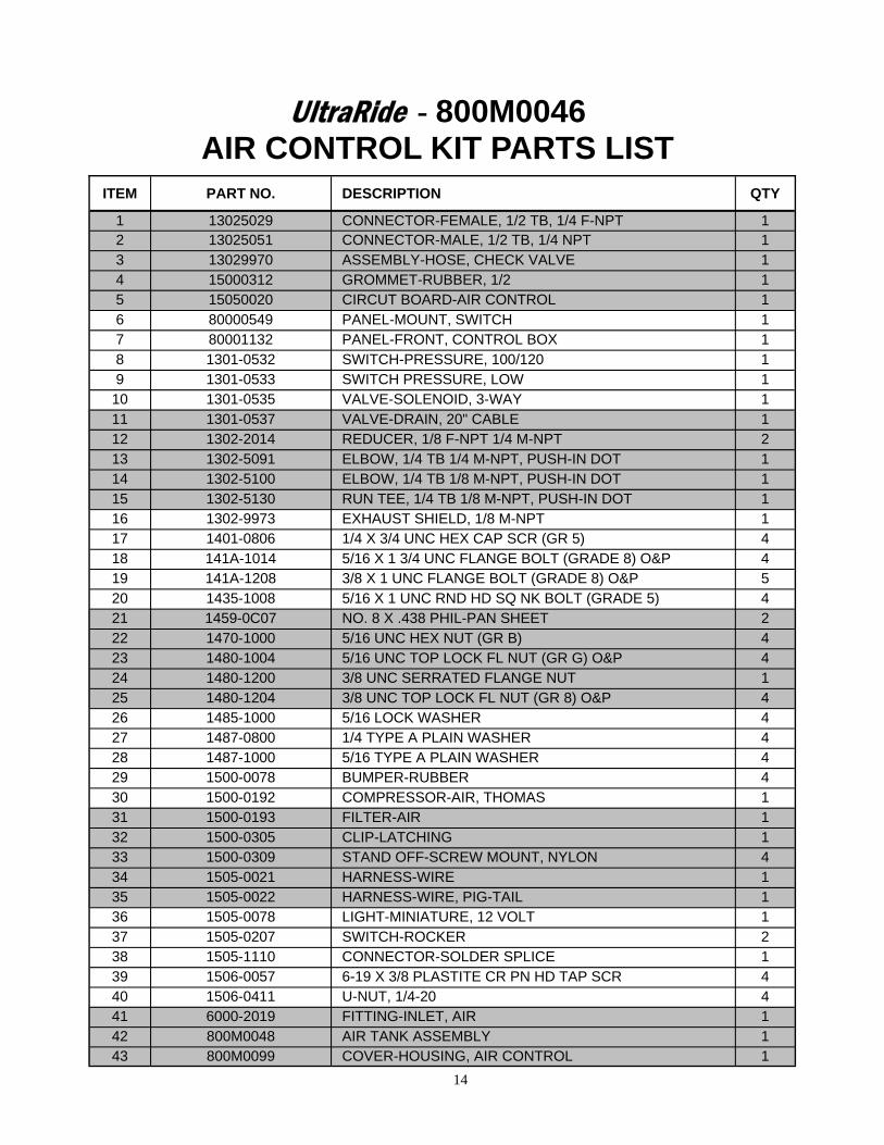
UltraRide - 800M0046 AIR CONTROL KIT PARTS LIST
ITEM PART NO. DESCRIPTION QTY
1 13025029 CONNECTOR-FEMALE, 1/2 TB, 1/4 F-NPT 1 2 13025051 CONNECTOR-MALE, 1/2 TB, 1/4 NPT 1 3 13029970 ASSEMBLY-HOSE, CHECK VALVE 1 4 15000312 GROMMET-RUBBER, 1/2 1 5 15050020 CIRCUT BOARD-AIR CONTROL 1 6 80000549 PANEL-MOUNT, SWITCH 1 7 80001132 PANEL-FRONT, CONTROL BOX 1 8 1301-0532 SWITCH-PRESSURE, 100/120 1 9 1301-0533 SWITCH PRESSURE, LOW 1
10 1301-0535 VALVE-SOLENOID, 3-WAY 1 11 1301-0537 VALVE-DRAIN, 20" CABLE 1 12 1302-2014 REDUCER, 1/8 F-NPT 1/4 M-NPT 2 13 1302-5091 ELBOW, 1/4 TB 1/4 M-NPT, PUSH-IN DOT 1 14 1302-5100 ELBOW, 1/4 TB 1/8 M-NPT, PUSH-IN DOT 1 15 1302-5130 RUN TEE, 1/4 TB 1/8 M-NPT, PUSH-IN DOT 1 16 1302-9973 EXHAUST SHIELD, 1/8 M-NPT 1 17 1401-0806 1/4 X 3/4 UNC HEX CAP SCR (GR 5) 4 18 141A-1014 5/16 X 1 3/4 UNC FLANGE BOLT (GRADE 8) O&P 4 19 141A-1208 3/8 X 1 UNC FLANGE BOLT (GRADE 8) O&P 5 20 1435-1008 5/16 X 1 UNC RND HD SQ NK BOLT (GRADE 5) 4 21 1459-0C07 NO. 8 X .438 PHIL-PAN SHEET 2 22 1470-1000 5/16 UNC HEX NUT (GR B) 4 23 1480-1004 5/16 UNC TOP LOCK FL NUT (GR G) O&P 4 24 1480-1200 3/8 UNC SERRATED FLANGE NUT 1 25 1480-1204 3/8 UNC TOP LOCK FL NUT (GR 8) O&P 4 26 1485-1000 5/16 LOCK WASHER 4 27 1487-0800 1/4 TYPE A PLAIN WASHER 4 28 1487-1000 5/16 TYPE A PLAIN WASHER 4 29 1500-0078 BUMPER-RUBBER 4 30 1500-0192 COMPRESSOR-AIR, THOMAS 1 31 1500-0193 FILTER-AIR 1 32 1500-0305 CLIP-LATCHING 1 33 1500-0309 STAND OFF-SCREW MOUNT, NYLON 4 34 1505-0021 HARNESS-WIRE 1 35 1505-0022 HARNESS-WIRE, PIG-TAIL 1 36 1505-0078 LIGHT-MINIATURE, 12 VOLT 1 37 1505-0207 SWITCH-ROCKER 2 38 1505-1110 CONNECTOR-SOLDER SPLICE 1 39 1506-0057 6-19 X 3/8 PLASTITE CR PN HD TAP SCR 4 40 1506-0411 U-NUT, 1/4-20 4 41 6000-2019 FITTING-INLET, AIR 1 42 800M0048 AIR TANK ASSEMBLY 1 43 800M0099 COVER-HOUSING, AIR CONTROL 1

15
UltraRide - 800M0046 AIR CONTROL KIT

16
ULTRARIDE AIR CONTROL KITS OWNER GUIDELINES
The UltraRide Air Control Kits need no lubrication and little maintenance. However, immediate cor-rective action should be taken if a serious malfunction occurs.
PRODUCT OWNER RESPONSIBILITIES Owner is solely responsible for pre-operation inspection, periodic inspections, maintenance,
and use of the product as specified in the particular LINK MFG. instructions available by prod-uct model, except as provided in this warranty, and for maintenance of other vehicle compo-nents.
Owner is responsible for “down time” expenses, cargo damage, and all business costs and losses resulting from a warrantable failure.
Maintenance Note: It is important to release any moisture contained within the air reservoir on a daily basis. This can be done by pulling on the cable attached to the drain valve. Not releasing the moisture on a regular basis will cause the drain valve to not operate properly, and may cause the valve to malfunction. Excess moisture in the system can also cause premature failure of other components including the tank itself. Operational Notes: Compressor switch should stay on the ON position at all times to keep the system energized. It
should be turned OFF when completing service work or in difficult starting conditions. LOW PRESSURE light indicates low air pressure in the system resulting from possible system
leak and correction action should be taken immediately. CHECK AT EVERY VEHICLE SERVICE INTERVAL:
Check for air leaks around fittings Check air filter; replace if necessary
CHECK AFTER EVERY 30,000 MILES:
Change motor brushes on heavy-duty compressor
CAUTION! If maintenance or service is to be done on the air system, be sure to drain all air from the system. Serious injury could occur if components are removed while system is full of air.
17
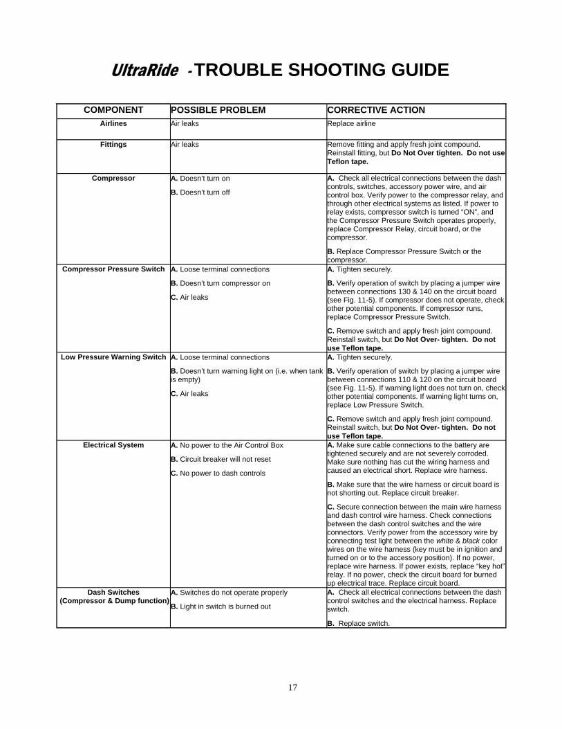
COMPONENT POSSIBLE PROBLEM CORRECTIVE ACTION Airlines Air leaks Replace airline
Fittings Air leaks Remove fitting and apply fresh joint compound. Reinstall fitting, but Do Not Over tighten. Do not use Teflon tape.
Compressor A. Doesn’t turn on
B. Doesn’t turn off
A. Check all electrical connections between the dash controls, switches, accessory power wire, and air control box. Verify power to the compressor relay, and through other electrical systems as listed. If power to relay exists, compressor switch is turned “ON”, and the Compressor Pressure Switch operates properly, replace Compressor Relay, circuit board, or the compressor.
B. Replace Compressor Pressure Switch or the compressor.
Compressor Pressure Switch A. Loose terminal connections
B. Doesn’t turn compressor on
C. Air leaks
A. Tighten securely.
B. Verify operation of switch by placing a jumper wire between connections 130 & 140 on the circuit board (see Fig. 11-5). If compressor does not operate, check other potential components. If compressor runs, replace Compressor Pressure Switch.
C. Remove switch and apply fresh joint compound. Reinstall switch, but Do Not Over- tighten. Do not use Teflon tape.
Low Pressure Warning Switch A. Loose terminal connections
B. Doesn’t turn warning light on (i.e. when tank is empty)
C. Air leaks
A. Tighten securely.
B. Verify operation of switch by placing a jumper wire between connections 110 & 120 on the circuit board (see Fig. 11-5). If warning light does not turn on, check other potential components. If warning light turns on, replace Low Pressure Switch.
C. Remove switch and apply fresh joint compound. Reinstall switch, but Do Not Over- tighten. Do not use Teflon tape.
Electrical System A. No power to the Air Control Box
B. Circuit breaker will not reset
C. No power to dash controls
A. Make sure cable connections to the battery are tightened securely and are not severely corroded. Make sure nothing has cut the wiring harness and caused an electrical short. Replace wire harness.
B. Make sure that the wire harness or circuit board is not shorting out. Replace circuit breaker.
C. Secure connection between the main wire harness and dash control wire harness. Check connections between the dash control switches and the wire connectors. Verify power from the accessory wire by connecting test light between the white & black color wires on the wire harness (key must be in ignition and turned on or to the accessory position). If no power, replace wire harness. If power exists, replace “key hot” relay. If no power, check the circuit board for burned up electrical trace. Replace circuit board.
Dash Switches (Compressor & Dump function)
A. Switches do not operate properly
B. Light in switch is burned out
A. Check all electrical connections between the dash control switches and the electrical harness. Replace switch.
B. Replace switch.
UltraRide - TROUBLE SHOOTING GUIDE

18
PAGE INTENTIONALLY LEFT BLANK

19
APPENDIX A WIRING DETAIL FOR F-SERIES FORD VEHICLES
Harness Routing: Another option in routing the harness is to run the harness under the floor-pan of the passenger’s side, and through the grommet in the passen-ger side floor, if available. The har-ness can then run under the floor covering and behind the dash. See Figure A-1
Key Hot Wire Selection: For ‘99 and newer Ford vehicles, the PTO 12-volt power source wire pro-vides an adequate “key hot” wire for the UltraRide Air Kit.
It is located under the dash to the right of the steering column. For 2002 and newer models, it is with the wire harness that goes to the Diagnostic Link Connector (DLC).
For pre-2002 model year vehicles, the wire is Circuit Number 295 and has a color code of light blue and pink.
For 2002 and newer model year vehicles, the wire is Circuit Number 294 and has a color code of white and light blue. See Figures A-2 and A-3.
This wire does not have any terminals attached to it, and is part of the OE supplied Power Take-Off Circuits. To verify the correct wire, use a test light or multimeter. The selected wire should only be “hot” when the ignition switch is on.
FIG. A-1
FIG. A-3
FIG. A-2

20
PAGE INTENTIONALLY LEFT BLANK

21
APPENDIX B WIRING DETAIL FOR GMC VEHICLES
Harness Routing: Another option in routing the harness is to run the harness from the battery, up through the grommeted hole in the pas-senger side bulkhead. The harness can then run under the floor covering and be-hind the dash. See Figures B-1, B-2, & B-3.
FIG. B-1
Remove fender well cover
FIG. B-2
Bulkhead access through grommet (shown from engine compartment)
FIG. B-3
Bulkhead access through grommet (shown from inside on passenger side)

22
APPENDIX B (CONTINUED)
Key Hot Wire Selection: For GMC vehicles, any wire connected to IGN4 provides an adequate “key hot” wire for the UltraRide Air Kit. One such wire that can be used is connected to the Clutch Pedal Position Switch located be-hind the left front kick panel. This wire is hot and fused with the ignition key in the “RUN” position. It may be necessary to remove the kick panel to access this connector. See Figures B-4 and B-5.
To verify the correct wire, use a test light or multimeter. The selected wire should only be “hot” when the ignition switch is on.
Remove Left Front Kick Panel
FIG. B-4
Clutch Pedal Position Switch (shown with supplied connector attached)
FIG. B-5


![Starsin, Owners of cargo v Starsin, Owners &/or demise ... 2003.pdf · Starsin, Owners of cargo v Starsin, Owners &/or demise charterers [2003] APP.L.R. 03/13 ... owners under these](https://static.fdocuments.net/doc/165x107/5b34b4ba7f8b9aa0238e4fb6/starsin-owners-of-cargo-v-starsin-owners-or-demise-2003pdf-starsin.jpg)