Owner’s Manual Operational Guide Warranty - … · 4 To the lucky new owner of this GT40 Brady...
61
Transcript of Owner’s Manual Operational Guide Warranty - … · 4 To the lucky new owner of this GT40 Brady...
Owner’s Manual Operational Guide
Warranty
1
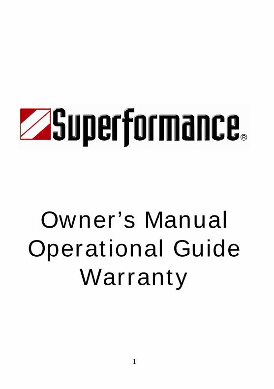
Authorized Dealer
Superformance Chassis Number: Model: ______________________________ Color: ______________________________ Stripes: ______________________________ Purchased by: ______________________________ Purchase Date: ______________________________
2
3
Superformance® Owners Manual, Operational Guide, and Warranty Copyright © 1998-2002 by Superformance LLC. Superformance® is a registered trademark of Superformance LLC. Printed in RSA.
4
To the lucky new owner of this GT40
Brady Pack, John Sadler, and Bob Wood, the three partners of Safir GT40® Spares, Limited, would like to congratulate you on the purchase of this rare vehicle. As you might or might not know, Safir GT40® Spares, Limited holds the rights to the famous GT40® trademark, and supplies parts and technical information to the owners of the original GT40® cars. Safir also keeps the records of the MkVs, and with Superformance will maintain a registry of your car. These registries are combined at various times with the registry of The Shelby American Automotive Club, and the written works of such GT40® authorities as Ronnie Spain and John Allen. We hope that you will enjoy this GT40® as much as we and so many others do enjoy our cars. The Superformance GT40® allows you, the owner, to drive a high performance sports car while at the same time offering a comfortable ride with room to thrill a passenger! The styling is unique and true to the original cars, and the build quality and the attention to detail of Hitech Automotive and Superformance makes this vehicle worthy of the great GT40® name. You will now be driving a descendant of the car that became the “Legend of LeMans”. Drive carefully, good luck, and enjoy the ride! Brady Pack John Sadler Bob Wood
5
Lance Stander of Superformance LLC and Jimmy Price of Hi-Tech Automotive would like to extend their thanks and congratulate you on your purchase of the Superformance GT40. You now own a piece of one of the greatest accomplishments in racing history. With four victories at Le Mans the GT40 assured its immortality in the minds of motor sports enthusiasts world wide. Four years of development went into the recreation of the SPF GT40 and the result is a masterpiece of beauty that is evident to the eye matched with precision engineering that can only be measured from behind the wheel. An intimate connection between driver and car. One that can only be explained through the driving experience. We hope that you enjoy your Superformance GT40 and the memories that are yet to be created. On behalf of the entire Superformance and Hi-Tech family we thank you for your purchase and hope you enjoy its history, beauty, and performance for many years to come. Now you can have your cake and eat it too! Lance Stander Jimmy Price
GENERAL SPECIFICATIONS
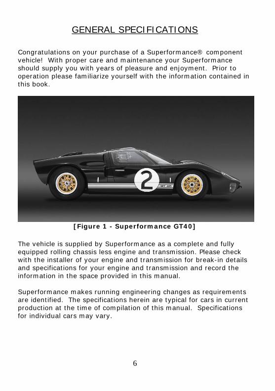
Congratulations on your purchase of a Superformance® component vehicle! With proper care and maintenance your Superformance should supply you with years of pleasure and enjoyment. Prior to operation please familiarize yourself with the information contained in this book.
[Figure 1 - Superformance GT40]
The vehicle is supplied by Superformance as a complete and fully equipped rolling chassis less engine and transmission. Please check with the installer of your engine and transmission for break-in details and specifications for your engine and transmission and record the information in the space provided in this manual. Superformance makes running engineering changes as requirements are identified. The specifications herein are typical for cars in current production at the time of compilation of this manual. Specifications for individual cars may vary.
6
7
Chassis: Jig-Welded monocoque.
Body:
Composite construction. Hand laid fiberglass panels with Vinyl ester resin.
Front suspension:
Original style, fully independent suspension using unequal length A- arm design, coil springs over telescopic shock absorbers, adjustable ride height and anti roll bar.
Rear suspension: Original style, fully independent suspension using radius rods, unequal length A arm design, with a toe control link, adjustable coil springs over telescopic shock absorbers, adjustable ride height and anti roll bar.
Steering: Rack and pinion with 2.5 turns lock to lock.
Pedal box:
Floor mounted pedals. Adjustable pedal box. Brakes:
Non-assisted brake system. Separate front and rear master cylinders. Adjustable front to rear brake bias via balance bar. Calipers: Front - 4-pot Rear - 4-pot Ventilated discs: Front – 12.75” x 1.25” Rear – 12.75” x 1.25”
Cooling: High performance aluminum two-core radiator. Two thermostatically-controlled electric fans.
Exhaust system:
Original style fabricated headers (bundle of snakes) incorporating full crossover design.
Interior:
The cockpit is trimmed in top quality automotive carpeting, and Alcantara™. 4-point seat belts. Original style 14” Motolita™ steering wheel. Rear view mirror. Your Superformance GT40 has 2 stowage compartments. These are located in each of the doors.
MECHANICAL COMPONENTS Engine:
As the Superformance GT40 is a copy of the original GT40 chassis, it can therefore accommodate anything from a 302 small block to a 427FE big block.
Drive train:
The Superformance GT40 can use a choice of either ZF 5-DS25 or T44 Transaxles.
Front Wheels:
Aluminum 15" x 8” “Halibrand” or “BRM” pattern peg drive. Rear Wheels:
Aluminum 15” x 10” “Halibrand” or “BRM” pattern peg drive. Tires:
Front - 225/50 R-15 (Recommended MkI & MkII) Rear - 295/50 R-15 (Recommended MkI)
275/60 R-15 (Recommended MkII)
Fuel Tank:
Two stainless steel tanks connected via crossover line. 10.5 gallon each.
8
9
DIMENSIONS:
Wheelbase: 95” Length: 163” Height: 40.5” Width: (Overall) 70” Track Front: 57” Track Rear: 56” Ground clearance: 4.125”- 4.75” Curb Weight: 2400lbs Weight distribution: F/R: 40 / 60%
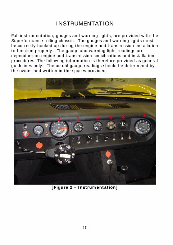
INSTRUMENTATION Full instrumentation, gauges and warning lights, are provided with the Superformance rolling chassis. The gauges and warning lights must be correctly hooked up during the engine and transmission installation to function properly. The gauge and warning light readings are dependant on engine and transmission specifications and installation procedures. The following information is therefore provided as general guidelines only. The actual gauge readings should be determined by the owner and written in the spaces provided.
[Figure 2 - Instrumentation]
10
11
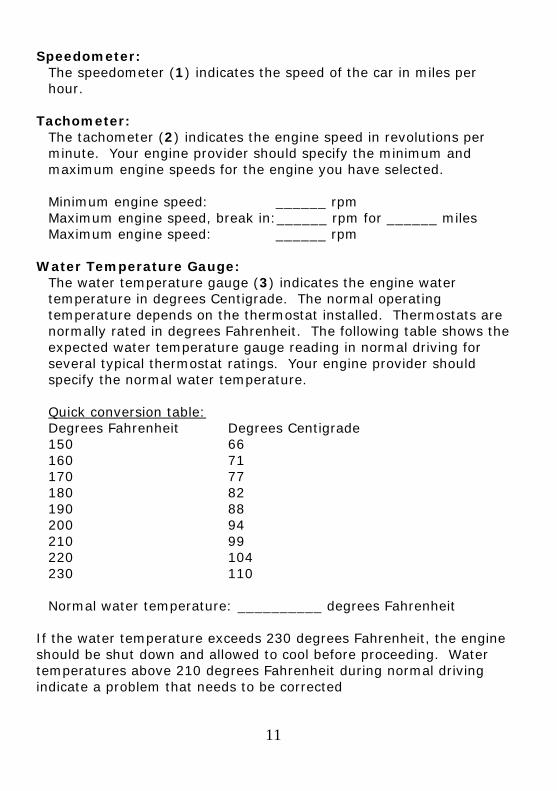
Speedometer: The speedometer (1) indicates the speed of the car in miles per hour.
Tachometer:
The tachometer (2) indicates the engine speed in revolutions per minute. Your engine provider should specify the minimum and maximum engine speeds for the engine you have selected. Minimum engine speed: ______ rpm Maximum engine speed, break in:______ rpm for ______ miles Maximum engine speed: ______ rpm
Water Temperature Gauge: The water temperature gauge (3) indicates the engine water temperature in degrees Centigrade. The normal operating temperature depends on the thermostat installed. Thermostats are normally rated in degrees Fahrenheit. The following table shows the expected water temperature gauge reading in normal driving for several typical thermostat ratings. Your engine provider should specify the normal water temperature. Quick conversion table: Degrees Fahrenheit Degrees Centigrade 150 66 160 71 170 77 180 82 190 88 200 94 210 99 220 104 230 110 Normal water temperature: __________ degrees Fahrenheit
If the water temperature exceeds 230 degrees Fahrenheit, the engine should be shut down and allowed to cool before proceeding. Water temperatures above 210 degrees Fahrenheit during normal driving indicate a problem that needs to be corrected
12
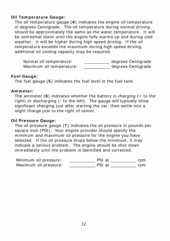
Oil Temperature Gauge: The oil temperature gauge (4) indicates the engine oil temperature in degrees Centigrade. The oil temperature during normal driving should be approximately the same as the water temperature. It will be somewhat lower until the engine fully warms up and during cold weather. It will be higher during high speed driving. If the oil temperature exceeds the maximum during high speed driving, additional oil cooling capacity may be required. Normal oil temperature: __________ degrees Centigrade Maximum oil temperature: __________ degrees Centigrade
Fuel Gauge: The fuel gauge (5) indicates the fuel level in the fuel tank.
Ammeter:
The ammeter (6) indicates whether the battery is charging (+ to the right) or discharging (- to the left). The gauge will typically show significant charging just after starting the car, then settle into a slight charge just to the right of center.
Oil Pressure Gauge:
The oil pressure gauge (7) indicates the oil pressure in pounds per square inch (PSI). Your engine provider should specify the minimum and maximum oil pressure for the engine you have selected. If the oil pressure drops below the minimum, it may indicate a serious problem. The engine should be shut down immediately until the problem is identified and corrected. Minimum oil pressure: __________ PSI at __________ rpm Maximum oil pressure: __________ PSI at __________ rpm
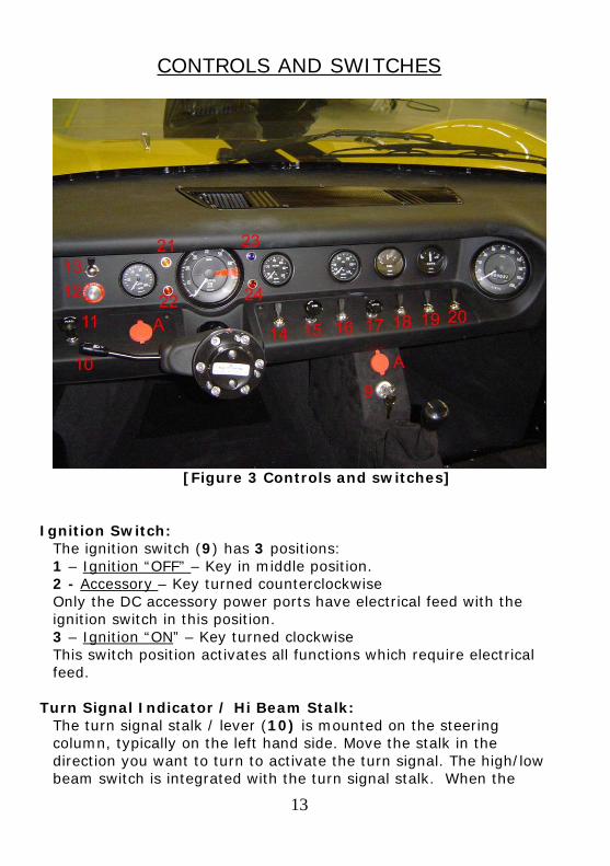
CONTROLS AND SWITCHES
[Figure 3 Controls and switches] Ignition Switch:
The ignition switch (9) has 3 positions: 1 – Ignition “OFF” – Key in middle position. 2 - Accessory – Key turned counterclockwise Only the DC accessory power ports have electrical feed with the ignition switch in this position. 3 – Ignition “ON” – Key turned clockwise This switch position activates all functions which require electrical feed.
Turn Signal Indicator / Hi Beam Stalk:
The turn signal stalk / lever (10) is mounted on the steering column, typically on the left hand side. Move the stalk in the direction you want to turn to activate the turn signal. The high/low beam switch is integrated with the turn signal stalk. When the
13
14
headlights are turned on, pull the stalk to switch between high beams and low beams. When the high beams are on, the hi-beam pilot light will be on. When the headlights are not on, pulling the stalk flashes the high beams.
Horn:
The horn button is located at the end of the turn signal stalk. Pushing the button sounds the horn.
Dash dimmer switch:
The dashboard dimmer switch (11) is situated on the dash and is used to control the intensity of the dashboard lights. Turn the dimmer switch counterclockwise to dim the dashboard lights and clockwise to brighten them.
Start Button:
This button (12) is depressed to start the engine. (See Start Procedure on page16)
Fuel Pump Toggle Switch:
The fuel pump switch (13) controls the electric fuel pump. Up is off and down is on. Be sure to turn the fuel pump on before starting the car. Although the electric fuel pump shuts off when the ignition is turned off, it is a good idea to turn off the electric fuel pump switch as well. Remember to turn it back on when you start the car. If the pump is switched off (up), the car may start, but will shut down in a short while when the fuel supply in the carburetor bowl is used up.
Radiator Fan Override Toggle Switch:
The radiator fans are switched on automatically when the engine temperature exceeds 203 to 207 degrees Fahrenheit. The radiator fan override toggle switch (14) enables you to turn the radiator fans on manually when the water temperature gauge indicates that the engine temperature is approaching 203 degrees Fahrenheit, typically in slow traffic. Up is off and down is on.
Windshield Washer Toggle Switch:
The windshield washer can be activated by toggling switch (16) upwards or downwards
15
Windshield Wiper Rotary Switch:
The two speed windshield wiper switch (17) has 3 positions P Park (off) N Normal (low) speed wiper
H High speed wiper From park, rotate the switch clockwise one position for low speed wiper operation and two positions for high speed wiper operation. Rotate the switch counterclockwise to slow or turn off the wipers.
Headlight Toggle Switch:
Toggle the headlight switch (18) to the full up position to turn off the lights. Toggle the switch down one position to turn on the running lights and down two positions to turn on the headlights. The dashboard lights come on automatically when the running lights or headlights are switched on.
Spot Light Toggle Switch:
Toggle the switch (19) downward to switch on the spot lights Number Light Toggle Switch:
(Optional) All GT40’s have plugs in the door loom for the connection of a light on the door to illuminate the racing number. Toggle the switch (20) downward to activate this light.
Indicator repeater:
The indicator repeater (21) blinks to indicate that the turn signals are illuminated.
Ignition / Alternator Warning Light:
It is normal for the Ignition / alternator warning light (22) to be on when the ignition is on and the engine is not running. If the Ignition / alternator warning light are on for more than a few seconds when the engine is running, it indicates a problem with the alternator. It may be that the v-belt is loose or missing. It may be an electrical problem. Immediate attention is required. A loose or missing v-belt can cause the engine to overheat.
Hi Beam Pilot Light:
The hi-beam pilot light (23) indicates that the headlight high beams are on.
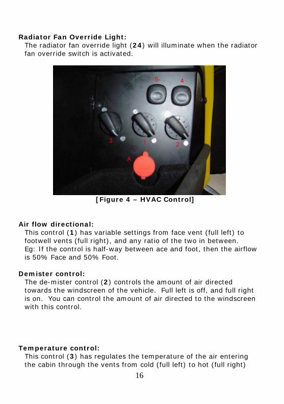
Radiator Fan Override Light:
The radiator fan override light (24) will illuminate when the radiator fan override switch is activated.
[Figure 4 – HVAC Control]
Air flow directional:
This control (1) has variable settings from face vent (full left) to footwell vents (full right), and any ratio of the two in between. Eg: If the control is half-way between ace and foot, then the airflow is 50% Face and 50% Foot.
Demister control: The de-mister control (2) controls the amount of air directed towards the windscreen of the vehicle. Full left is off, and full right is on. You can control the amount of air directed to the windscreen with this control.
Temperature control:
This control (3) has regulates the temperature of the air entering the cabin through the vents from cold (full left) to hot (full right)
16
17
Air flow source: The re-circulate button (4) determines whether the source of air is fresh or re-circulated.
Air-Conditioning:
Push Air-Conditioning button (5) to engage or disengage the air conditioning compressor.
Adjustable air vents:
These dash mounted vents are fully adjustable in all directions and are situated on the far left and right of the dash.
DC power accessory ports:
These can be used to supply power to 12 volt plug-in automotive accessories (See Figures 3 & 4 – item “A” above)
Hand brake:
To apply the hand brake, pull the handle upwards while depressing the button at the end of the lever. Release the button at the end of the lever’s travel. To release, press the button and lower the lever fully.
18
VEHICLE OPERATION
START PROCEDURE: 1 Apply the handbrake and insert the key into the ignition.
2 Depress the clutch pedal. Put the gear lever into neutral.
3 Turn the key clockwise to position II to activate the
electrical circuits.
4 Turn on the fuel pump (See Figure 3 – item #13) (You should be able to hear it pressurizing the system).
5 Turn the key to momentary position III or depress the start button to engage the starter motor. The engine should start immediately; if not, repeat the stages detailed above.
IMPORTANT: Only short repeated engine cranking periods should be used, as long cranking periods cause unnecessary wear to the starter motor and cause un-burnt fuel to be deposited into the exhaust system. Turn the ignition switch counterclockwise to turn the engine off. The key cannot be removed from the ignition switch unless the ignition switch is in the off position. DO NOT engage the starter if the engine is running. Serious damage to the starter and engine can result DO NOT leave the ignition switched on when the engine is not running. Damage to the ignition system can result.
RUNNING IN PROCEDURE: The benefits of gradually ‘running in’ your Superformance GT40 are many and varied, but a major factor is to enable the new engine components to bed-in properly. For your vehicle to run at its optimum performance it is important that the car avoids high engine rpm and heavy throttle opening during the periods detailed below.
Engine:
Your engine builder should specify the correct running in procedure for your engine.
Tires:
It is advised that you should avoid excessive braking and cornering over the first 1000 mile period, in order to achieve and prolong maximum tire performance.
Brakes:
It is advised that excessive braking should be kept to a minimum during the first 500 miles of driving to bed in the friction materials.
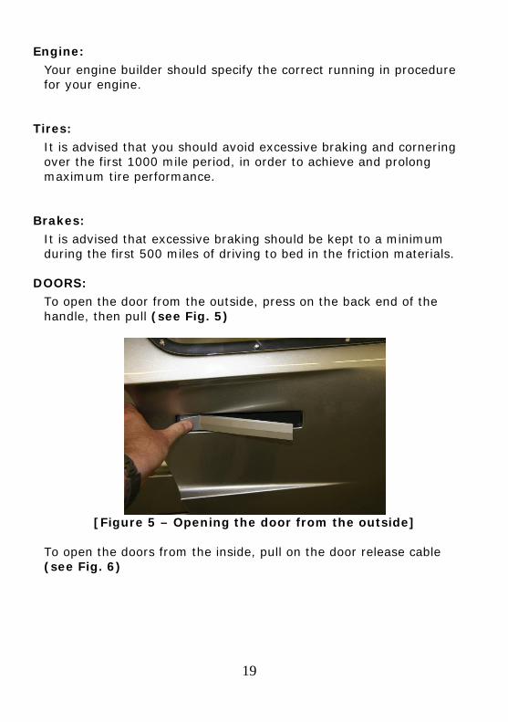
DOORS: To open the door from the outside, press on the back end of the handle, then pull (see Fig. 5)
[Figure 5 – Opening the door from the outside]
To open the doors from the inside, pull on the door release cable (see Fig. 6)
19
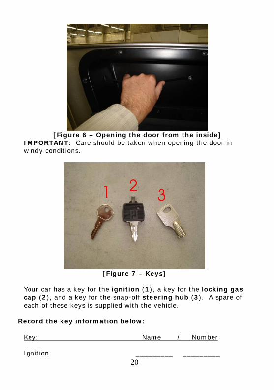
[Figure 6 – Opening the door from the inside]
IMPORTANT: Care should be taken when opening the door in windy conditions.
[Figure 7 – Keys]
Your car has a key for the ignition (1), a key for the locking gas cap (2), and a key for the snap-off steering hub (3). A spare of each of these keys is supplied with the vehicle.
Record the key information below:
Key: Name / Number Ignition _________ _________
20
Locking gas cap _________ _________
Steering hub _________ _________
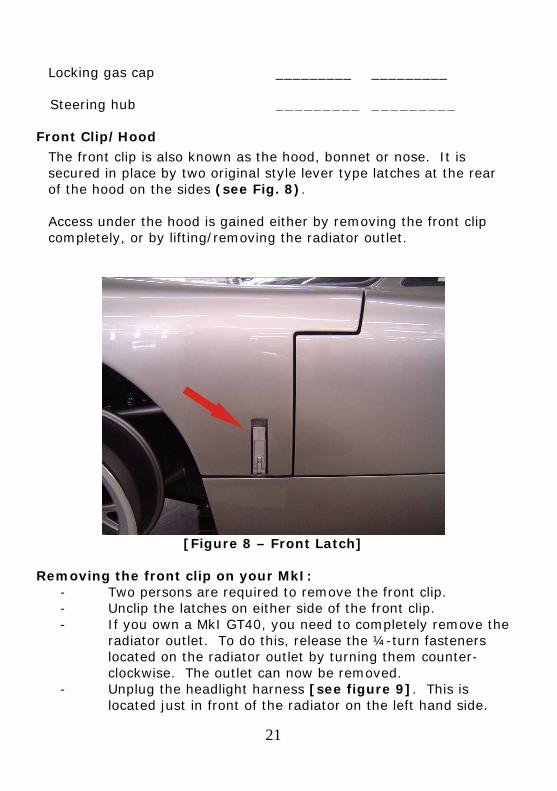
Front Clip/Hood The front clip is also known as the hood, bonnet or nose. It is secured in place by two original style lever type latches at the rear of the hood on the sides (see Fig. 8). Access under the hood is gained either by removing the front clip completely, or by lifting/removing the radiator outlet.
[Figure 8 – Front Latch]
Removing the front clip on your MkI:
- Two persons are required to remove the front clip. - Unclip the latches on either side of the front clip. - If you own a MkI GT40, you need to completely remove the
radiator outlet. To do this, release the ¼-turn fasteners located on the radiator outlet by turning them counter-clockwise. The outlet can now be removed.
- Unplug the headlight harness [see figure 9]. This is located just in front of the radiator on the left hand side.
21
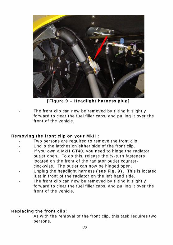
[Figure 9 – Headlight harness plug]
- The front clip can now be removed by tilting it slightly
forward to clear the fuel filler caps, and pulling it over the front of the vehicle.
Removing the front clip on your MkII:
- Two persons are required to remove the front clip - Unclip the latches on either side of the front clip. - If you own a MkII GT40, you need to hinge the radiator
outlet open. To do this, release the ¼-turn fasteners located on the front of the radiator outlet counter-clockwise. The outlet can now be hinged open.
- Unplug the headlight harness (see Fig. 9). This is located just in front of the radiator on the left hand side.
- The front clip can now be removed by tilting it slightly forward to clear the fuel filler caps, and pulling it over the front of the vehicle.
Replacing the front clip:
- As with the removal of the front clip, this task requires two persons.
22
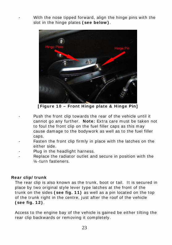
- With the nose tipped forward, align the hinge pins with the slot in the hinge plates (see below).
[Figure 10 – Front Hinge plate & Hinge Pin]
- Push the front clip towards the rear of the vehicle until it
cannot go any further. Note: Extra care must be taken not to foul the front clip on the fuel filler caps as this may cause damage to the bodywork as well as to the fuel filler caps.
- Fasten the front clip firmly in place with the latches on the either side.
- Plug in the headlight harness. - Replace the radiator outlet and secure in position with the
¼-turn fasteners.
Rear clip/trunk The rear clip is also known as the trunk, boot or tail. It is secured in place by two original style lever type latches at the front of the trunk on the sides (see fig. 11) as well as a pin located on the top of the trunk right in the centre, just after the roof of the vehicle (see fig. 12). Access to the engine bay of the vehicle is gained be either tilting the rear clip backwards or removing it completely.
23
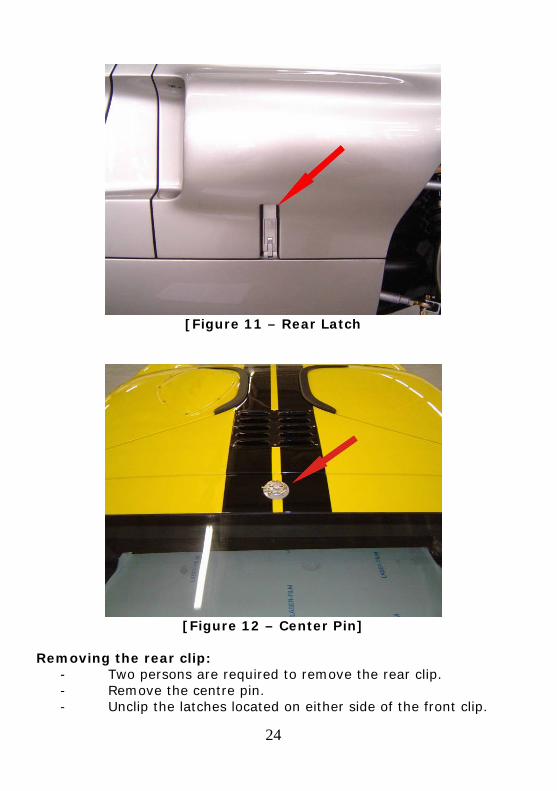
[Figure 11 – Rear Latch
[Figure 12 – Center Pin]
Removing the rear clip:
- Two persons are required to remove the rear clip. - Remove the centre pin. - Unclip the latches located on either side of the front clip.
24
- With one person on either side of the rear clip, carefully tilt the clip backwards.
- With one person holding the rear clip open, unplug the tail light harness.
- Once the rear clip has been tilted to near vertical, it can be lifted off its hinge pins.
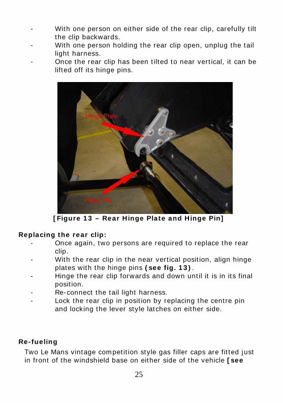
[Figure 13 – Rear Hinge Plate and Hinge Pin]
Replacing the rear clip:
- Once again, two persons are required to replace the rear clip.
- With the rear clip in the near vertical position, align hinge plates with the hinge pins (see fig. 13).
- Hinge the rear clip forwards and down until it is in its final position.
- Re-connect the tail light harness. - Lock the rear clip in position by replacing the centre pin
and locking the lever style latches on either side.
Re-fueling Two Le Mans vintage competition style gas filler caps are fitted just in front of the windshield base on either side of the vehicle [see
25
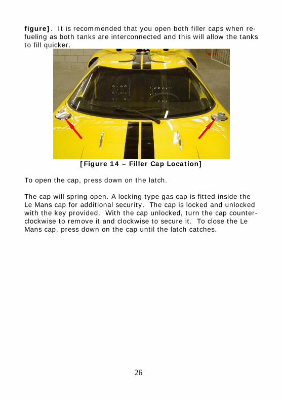
figure]. It is recommended that you open both filler caps when re-fueling as both tanks are interconnected and this will allow the tanks to fill quicker.
[Figure 14 – Filler Cap Location]
To open the cap, press down on the latch. The cap will spring open. A locking type gas cap is fitted inside the Le Mans cap for additional security. The cap is locked and unlocked with the key provided. With the cap unlocked, turn the cap counter-clockwise to remove it and clockwise to secure it. To close the Le Mans cap, press down on the cap until the latch catches.
26
27
GENERAL OPERATION
Seats The seats are custom moulded foam and are upholstered in Alcantara™. They are not adjustable. Adjustment for leg length can only be done by means of the adjustable pedal box. It is recommended that you let your dealer set the pedal box to your requirements.
Seat belts Your vehicle is fitted with a 4-point harness.
ROUTINE MAINTENANCE
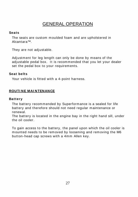
Battery The battery recommended by Superformance is a sealed for life battery and therefore should not need regular maintenance or renewal. The battery is located in the engine bay in the right hand sill, under the oil cooler. To gain access to the battery, the panel upon which the oil cooler is mounted needs to be removed by loosening and removing the M6 button-head cap screws with a 4mm Allen key.
[Figure 15 - Battery location ] Wheels and tires
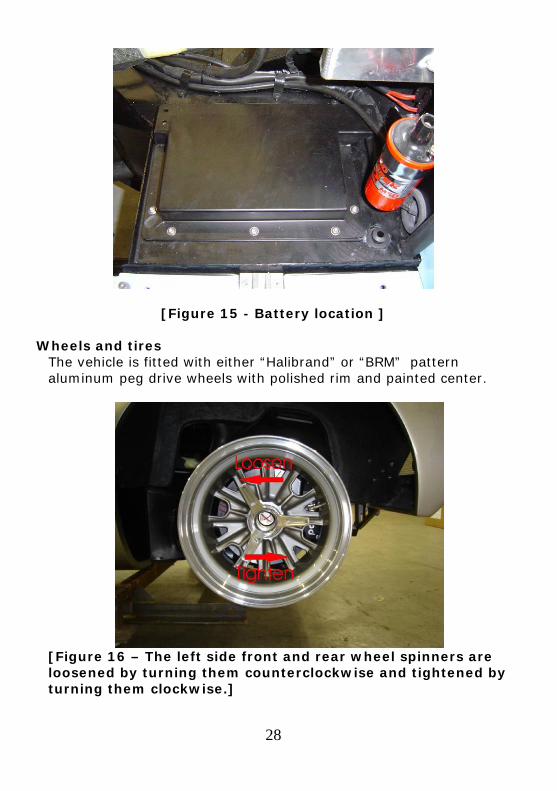
The vehicle is fitted with either “Halibrand” or “BRM” pattern aluminum peg drive wheels with polished rim and painted center.
[Figure 16 – The left side front and rear wheel spinners are loosened by turning them counterclockwise and tightened by turning them clockwise.]
28
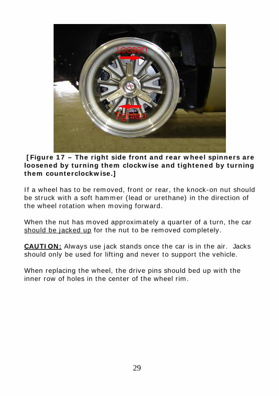
[Figure 17 – The right side front and rear wheel spinners are loosened by turning them clockwise and tightened by turning them counterclockwise.] If a wheel has to be removed, front or rear, the knock-on nut should be struck with a soft hammer (lead or urethane) in the direction of the wheel rotation when moving forward. When the nut has moved approximately a quarter of a turn, the car should be jacked up for the nut to be removed completely. CAUTION: Always use jack stands once the car is in the air. Jacks should only be used for lifting and never to support the vehicle. When replacing the wheel, the drive pins should bed up with the inner row of holes in the center of the wheel rim.
29
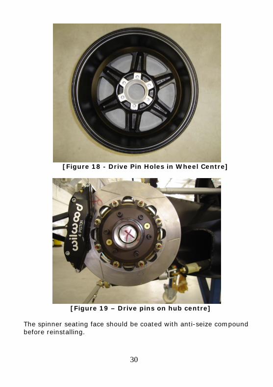
[Figure 18 - Drive Pin Holes in Wheel Centre]
[Figure 19 – Drive pins on hub centre] The spinner seating face should be coated with anti-seize compound before reinstalling.
30
31
The spinner nut is tightened in the reverse direction to forward wheel rotation. It is recommended that the spinner nut be tightened with a urethane hammer rather than a lead hammer to avoid over tightening. As the vehicles do not carry spare tires, it is advisable for the user of this vehicle to keep on hand at all times an aerosol inflatable tire product.
Tire pressures
It is important to check the tire pressures regularly, in order to maintain maximum performance characteristics and prevent excessive tire wear. Recommended Values: Always refer to the tire manufactures inflation requirements located on the tire sidewall.
ALIGNMENT SPECIFICATIONS
CAUTION: These settings are critical to the drivability of your vehicle and must only be adjusted by skilled individuals with the necessary experience. Consult your local dealer for a specialist in your area NOTE: When taking your vehicle in for wheel alignment, we strongly recommend that you supply them with a copy of the information below, to enable them to determine if they are capable of these technical adjustments
SUSPENSION SETTINGS
Please take careful note to the fact that both the front and rear suspensions are extremely sensitive to any minor adjustments. When setting the car up do not make major adjustments, rather make small incremental adjustments until the desired bump steer settings have been achieved. Any large adjustments change the
32
bump steer dramatically, which may cause you to think that it is impossible to achieve the suggested settings.
RECOMMENDED SETTINGS Camber Angle Front 0.5-1.0º Neg Rear 0.5-1.0º Neg Toe Front 15 minutes Total Rear 15 minutes Total Castor Angle Front Non-Adjustable Rear 7 – 8½º Adjusted to give
minimum toe-in change in bump and rebound positions.
Ride Height Front 4.125 – 4.5 inches Rear 4.5 – 4.75 inches Also – all of the settings and notes in this document are based on the recommended tires being fitted to the car.
33
ROUTINE CHECK UP AND LUBRICATION After the first 1000 miles, and thereafter every 5000 miles, the vehicle should be thoroughly checked for loose nuts, bolts, etc.
RECOMMENDED FLUIDS
Engine oil:
The engine oil change specifications depend on the engine installed. Your engine provider should provide the oil change specifications.
Oil capacity: __________ quarts Oil type:
Break in: ______________________ Routine: ______________________ High speed: ______________________
Oil change interval Break in: __________ miles Routine: __________ miles High speed: __________ miles Transmission:
The transmission fluid specifications depend on the transmission installed. Your transmission provider should provide the oil change specifications.
Fluid capacity: __________ quarts Fluid type: ______________________ Fluid change interval Break in: __________ miles Routine: __________ miles
Brake and Clutch Fluid
The brake and clutch fluid reservoirs are located in front of the windscreen base, under the nose, on either the left or right hand side.
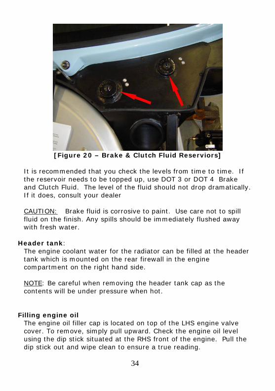
[Figure 20 – Brake & Clutch Fluid Reserviors]
It is recommended that you check the levels from time to time. If the reservoir needs to be topped up, use DOT 3 or DOT 4 Brake and Clutch Fluid. The level of the fluid should not drop dramatically. If it does, consult your dealer CAUTION: Brake fluid is corrosive to paint. Use care not to spill fluid on the finish. Any spills should be immediately flushed away with fresh water.
Header tank:
The engine coolant water for the radiator can be filled at the header tank which is mounted on the rear firewall in the engine compartment on the right hand side. NOTE: Be careful when removing the header tank cap as the contents will be under pressure when hot.
Filling engine oil
The engine oil filler cap is located on top of the LHS engine valve cover. To remove, simply pull upward. Check the engine oil level using the dip stick situated at the RHS front of the engine. Pull the dip stick out and wipe clean to ensure a true reading.
34
35
Re-insert the dip stick and remove once again. The level of oil should read between the min and max marks on the dip stick. Top up with the recommended oil if required
Oil usage notes: The oil level should be checked at operating temperature, immediately after stopping the vehicle. Running the car with an oil level above the maximum may cause oil wastage. Running the car with an oil level below the minimum could cause considerable damage to the engine. It is important that once the oil has been checked, the dip stick is securely replaced to avoid oil leakage. For track day usage the oil should be topped up to the maximum mark, and the oil level monitored throughout the day
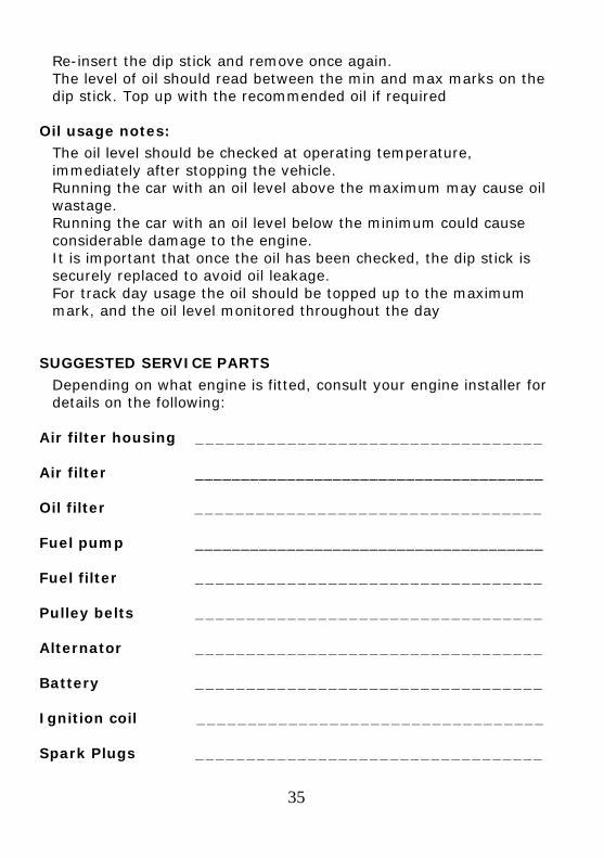
SUGGESTED SERVICE PARTS
Depending on what engine is fitted, consult your engine installer for details on the following:
Air filter housing __________________________________ Air filter ______________________________________ Oil filter __________________________________ Fuel pump ______________________________________ Fuel filter __________________________________ Pulley belts __________________________________ Alternator __________________________________ Battery __________________________________ Ignition coil __________________________________ Spark Plugs __________________________________
36
RECOMMENDED WEEKLY CHECKS
It is advisable to spend a small amount of time each week inspecting and checking the more fundamental components of the vehicle. The following constitutes a checklist for these inspections:
1 All exterior lights 2 Coolant level 3 Brake fluid level 4 Clutch / Power steering fluid 5 Windscreen washer bottle 6 Tire pressure 7 Visual check for any fluid leaks
RECOMMENDED DAILY CHECKS In addition to the above, it is recommended that the following checks are routinely carried out on a daily basis:
1 Oil level 2 Chassis
IMPORTANT
If for any reason the vehicle is grounded or an object strikes the chassis from below it is advisable to visually inspect the chassis for signs of damage. If there seems to be damage, the vehicle should be taken to your local Superformance dealer for a comprehensive inspection.
EXTERIOR CLEANING
By hand
The recommended method of cleaning your GT40 is to wash it by hand using a specialist car shampoo or mild detergent. A low pressure hose should then be used to rinse the vehicle before drying with Chamois leather. It is not advisable to use specialist cleaners on the vehicle wheels, or to use other specialist “road film” removal solvents.
37
Power wash
It is not recommended that a power or jet wash be used in the cleaning of your GT40. However, if you do decide to do so, ensure that the nozzle is not aimed directly at the window or door seals, at any intakes or ducts, at the door handles or at the door mirrors. It is also very important that the engine bay is not power washed at any point as it may cause serious electrical problems.
Automatic car wash The use of automatic car washes is not recommended. This is due to the door and window seals not being designed to withstand the direct force of high pressure jets, and also due to the profile of the vehicle being incompatible with many automated systems.
INTERIOR CLEANING
Plastics / Alcantara / leather / carpets Vinyl and leather should be cleaned regularly with a damp cloth. However, a small amount of mild detergent or specialist cleaner may be used on ingrained stains or blemishes. It is also recommended that leather upholstery is occasionally treated with a specialist “Hide food”. Carpets should be vacuumed regularly to remove dust and grime. Mild detergent in combination with warm water may be used on more stubborn stains.
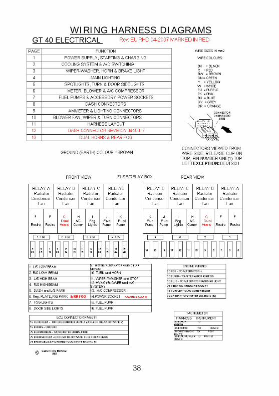
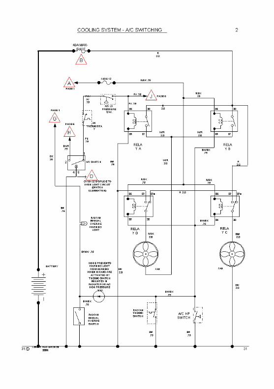
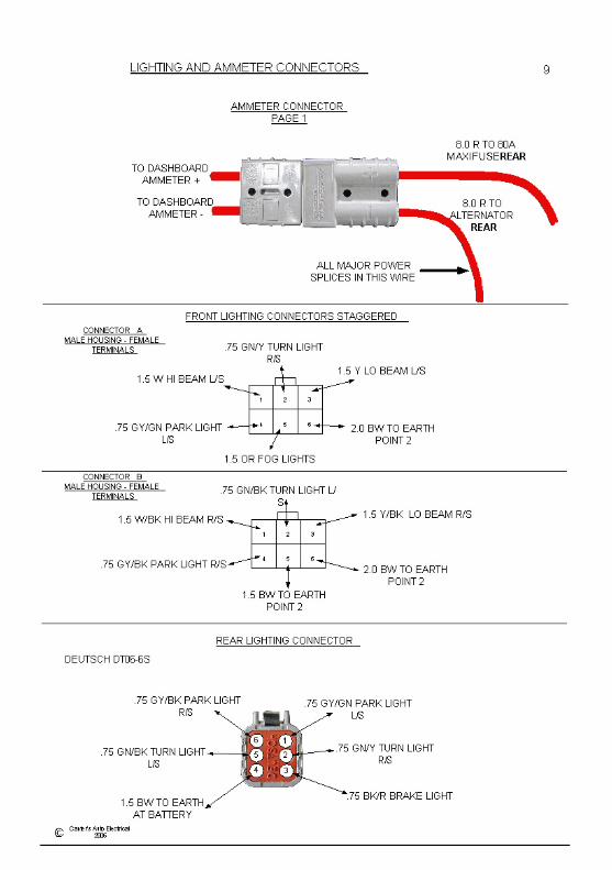
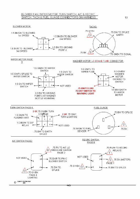
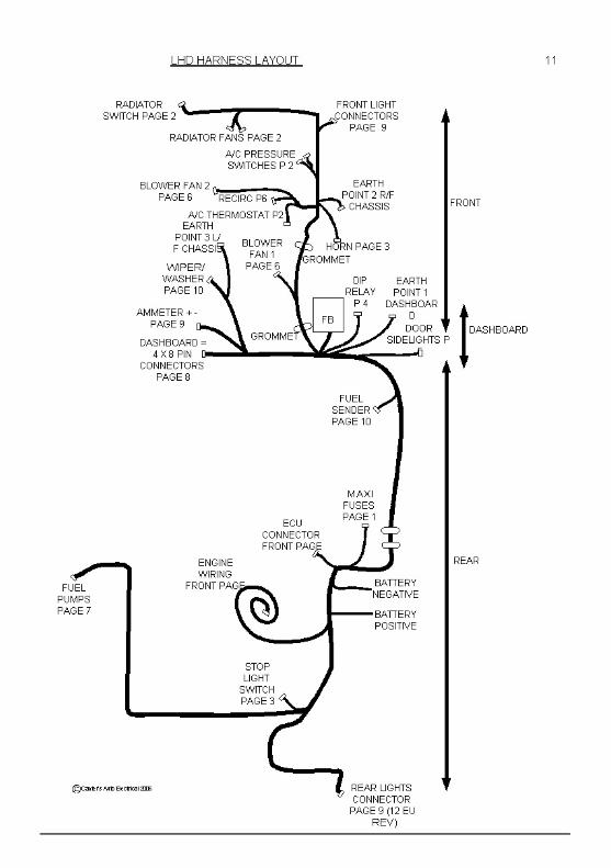
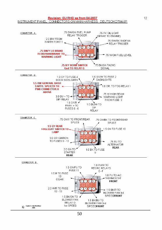
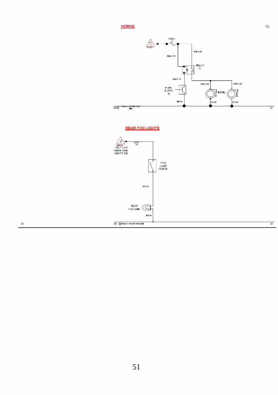
WIRING HARNESS DIAGRAMS
38
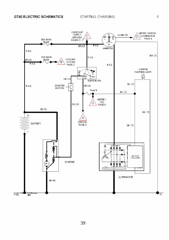
39
40
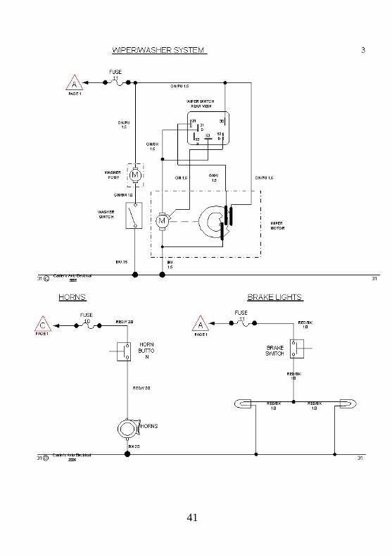
41
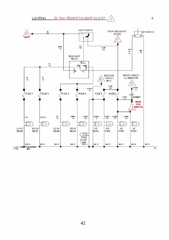
42
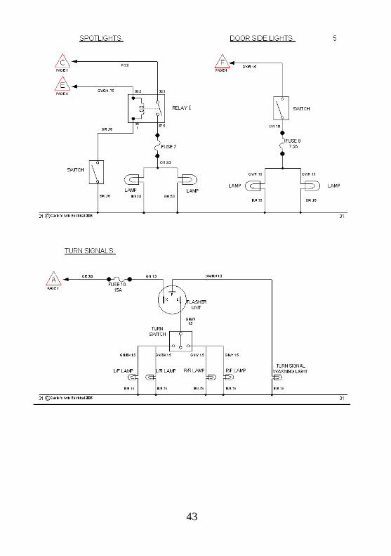
43
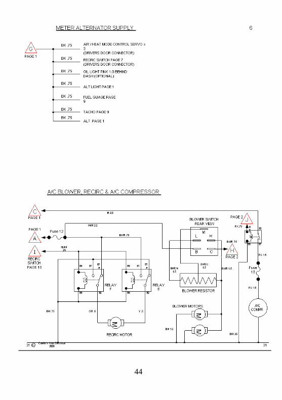
44
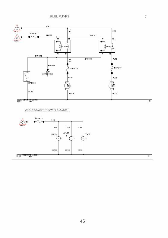
45
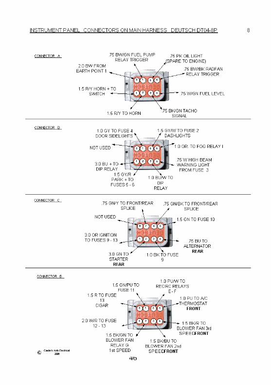
46
47
48
49
50
51
52
EXPRESS CONDITIONAL WARRANTIES, INSPECTION AND REPAIRS
IN GENERAL, it is the intention of Superformance LLC. and the Dealer, to provide our customers with a Superformance rolling chassis of unsurpassed quality, attention to detail, and safety. If the car succumbs to a mechanical defect covered by this warranty during the warranty period, we will remedy the problem at our expense. All we ask of the customer is that you properly care for and maintain your new car and if a problem should arise, not to entrust the matter to unauthorized service people. A. The seller shall provide an express one (1) year warranty of merchantability and fitness with respect to the chassis, fit and finish and all other standard features except for the electronic and wiring components pursuant to the following terms and conditions: 1. (a) Performance parts supplied by third party manufacturers shall not be warranted for a period beyond that which the part’s manufacturer supplies. Any resulting breakage of said parts shall be covered by the parts manufacturer’s independent warranty and said breakage shall not include any resulting labor costs by seller for removal and replacement of the part in question. (b) Engines and drive train parts shall not covered by this warranty. 2. Tires shall not be covered either expressly or implicitly by this warranty (the tires are covered by the tire maker’s independent warranty). 3. Electrical components including, but not limited to, wiring harnesses, fuse boxes, ignition systems, gauges, etc., shall carry a three (3) month warranty. 4. The vehicle’s paint shall be covered by a one (1) year conditional warranty against cracking, peeling, and/or any other defect resulting from seller’s workmanship, however, such warranties shall not apply to normal wear and tear or misuse. Such misuse
53
would include, but is not limited to, leaving the vehicle exposed in extreme climates for extended periods of time. 5. This express warranty is limited only to the items contained herein and shall in no way shape or form be construed by any party to this transaction to contain implicit warranties not expressly stated herein. 6. All portions of this warranty shall become null and void if the vehicle is used in any form of speed competition. 7. This warranty shall become void if unauthorized parties perform repairs to the vehicle. Authorized parties include those parties expressly designated as such in writing by the sellers. B. If in the event warranty repairs are required, the buyer shall place the seller on notice of the condition, at which time, the seller shall make best efforts to inspect and cure the defect. 1. Notice to seller shall take effect upon delivery of written correspondence confirming the condition. 2. Upon notice, the seller shall contact the buyer within ten (10) business days and shall make arrangements to inspect the alleged defect. 3. If the vehicle is operational, the buyer shall deliver the vehicle to seller for inspection of the defect. 4. Seller is not responsible for alternative transportation or alternative transportation costs while the vehicle is being serviced or repaired. 5. If the vehicle is non-operational then the vehicle may be repaired on site by an authorized repair agent or may require delivery to the seller’s service site. If in the discretion of the seller, it is determined that the vehicle will require service at the seller’s service site then the cost of delivering the vehicle shall be the burden of the buyer. If upon inspection by sellers it is determined that the defect is covered by the warranty then the seller shall reimburse buyer for all reasonable vehicle delivery costs.
54
6. If after inspection it is determined by seller that the condition is indeed covered under the warranty, then the seller shall have thirty (30) days to cure the problem. If in the event that new parts from a third party supplier or Superformance LLC are required and that delivery and installation of these new parts will require more than thirty (30) days then seller shall give notice to the buyer of this delay and shall thereafter use all best efforts to expedite the repair process, but, shall not be liable to buyer for any resulting financial liabilities. 7. Seller shall not be responsible nor obligated to cure damages caused to vehicle due to repairs, service, or modifications performed by unauthorized parties and, to the extent of such unauthorized service, repairs, and or modifications, the express warranty language contained in this document is hereby void. C. Repairs made to the vehicle during the warranty period carry an additional labor warranty of sixty (60) days or the remainder of the express conditional warranty, whichever is longer. D. Modifications performed by Superformance LLC, and/or the Dealer, after the date of sale and/or after the culmination of the warranty period shall carry a separate warranty to be determined by the parties at that time with such terms and conditions having no effect on any portion of this agreement. E. This warranty begins on the date that the vehicle is delivered to buyer or put into service by seller as a demonstrator. F. Warranty repairs and adjustments will be made at no charge except for those aforementioned items expressly stated above. G. This warranty gives the buyer specific legal rights which may vary from state to state. Neither Superformance LLC nor the Dealer assumes nor authorizes any other person or party to assume for them any other liability in connection with this vehicle. No payment or other compensation will be made for indirect or consequential damages, such as damage or injury to person or property or loss of revenue which might be paid or incurred by reason of failure of any part or assembly which may be repaired or replaced in accord with the terms of this warranty.
55
H. This warranty is applicable only to countries where Superformance LLC has appointed dealers. I. Damages due to accidents, negligence, misuse, objects striking the car, overloading, improper operation, lack of maintenance, poor fuel quality, environmental damages (e.g. tree sap, bird droppings, road salt, hail, airborne fallout) are not covered under this warranty. J. The seller reserves the right to make any changes in design or to make any additions to or upon its products without incurring any obligations to install the same equipment on motor vehicles previously built.
Miscellaneous Terms and Conditions
A. Severability: If any term, condition or clause contained herein shall be deemed by a court of proper jurisdiction to be void, void able, unconscionable, or otherwise unenforceable then said clause may be severed from this agreement with the remainder of same continuing to remain binding upon the parties herein. B. Litigation: If in the event litigation is required then the parties hereto by operation of contract bind themselves and submit to the jurisdiction of the courts of the county and state of the applicable Dealer. C. Assumption of Risk: By entering this agreement buyer is aware that the vintage sports car styled vehicle being purchased is a high performance vehicle which, in most cases, far exceeds the power to weight ratios of conventional vehicles and as such may be potentially dangerous and could cause injury or death to the operator or passenger of same. The safety features provided by the manufacturer are not a guarantee or bar against such injuries or death. Buyers are encouraged to take every safety precaution when operating this performance vehicle.
56
D. Refunds: Once vehicle delivery has been completed by seller and payment has been tendered in full by buyer the sale becomes final and as such no refunds will be made by sellers. E. Non-Affiliation: Neither Superformance LLC. nor the Dealer are affiliated either directly or indirectly with Ford Motor Company. F. Completeness: This agreement shall represent the total and complete embodiment of the buyer’s and seller’s intentions and shall supersede any prior or contemporaneous verbal or written agreements, promises, intentions and/or understandings between the parties.
Glossary
A. Assumption of Risk: Is a danger or possible danger that a reasonable party should either actually be aware of or should have been aware of. B. Certified Notice: Shall include the definition stated in Glossary Item (M), “Notice”, but shall require that such written transmissions be furnished from one party to another by way of the United States Postal Service in a certified format. C. Competition: Shall refer to any organized or unorganized contest of speed utilizing a Superformance LLC product as mode of transportation. D. Customer: Shall be defined in the same relative terms as those defined in Glossary Item (R), “Purchaser”. E. Defect: Shall refer to any condition which, in the discretion of the employees, agents or authorized representative of Superformance LLC and/or the Dealer, is deemed as a material departure from that of the designed or intended appearance or function of the vehicle. F. Down Payment: Shall refer to a partial financial payment offered by the purchaser to the seller for the express purpose of securing a purchase transaction.
57
G. Express Warranty: Shall be defined as those explicit promises made by the sellers to the purchaser contained herein and shall in no way be construed to include implied or additional promises or guarantees beyond those express warranties of merchantability and fitness as specified herein. H. Inspection: Shall refer to on-site examination of the vehicle in question by employees or agents of Superformance LLC and/or the Dealer. I. Labor: Shall refer to physical work required by Superformance LLC and/or Dealer employees for the purpose of repairing or maintaining the vehicle in question. J. Misuse: Shall refer to any application of Superformance products falling outside the reasonably anticipated use of the vehicle or its options. K. Notice: Shall refer to written correspondence which, among other things, confers a party’s intent or concerns. L. Options: Shall refer to any additional features not otherwise included on the standard features list as identified in the Superformance LLC sales brochure (herein incorporated by reference). M. Parts: Shall refer to any items and assemblies not otherwise manufactured by Superformance LLC or the Dealer. N. Payment: Shall refer to partial or total financial consideration proffered by purchaser to the Dealer, for products, repairs, modifications, and/or labor. O. Performance Modifications: Shall include any and all special requests made by the customer and/or purchaser which varies from the stock equipment offered on the vehicle. P. Power train: Shall refer to the vehicle’s engine, drive shaft, and transmission. (The terms “drive train” and “power train” are used interchangeably.)
58
Q. Product: Shall refer to the articles manufactured by Superformance LLC, distributed and serviced by the Dealer, and sold to the purchaser, less engine and transmission. R. Purchaser: Shall refer to the party or parties who take possession of the vehicle in question with the intent to maintain legal ownership of the vehicle. The term “purchaser” shall not include parties who receive the vehicle as a gift, a second purchaser, family members, heirs, transferees, and or any other party or parties who take possession of the vehicle after the original date of purchase. S. Seller: Shall refer to both the Dealer and Superformance LLC T. Side Exhausts and/or Side Pipes: Refers to the tubular pipes running from the outlet located behind the front wheels on either side of the vehicle and attached to the rocker panels below driver and passenger side door sills. Side Exhausts may or may not appear on the vehicle subject to this contract. U. Special Order: Shall refer to a vehicle ordered by the purchaser which is not currently in the Dealer’s vehicle inventory at the time such request is made by customer. V. Sports Car: Shall be defined as general styles of vehicles and shall in no way be construed as being affiliated with or otherwise attached to similar vehicles manufactured by any other manufacturer. W. Superformance International: Is a company operated and organized under the laws of the State of Ohio, whose chief responsibility is the distribution of Superformance products to its nationwide chain of dealers. X. Towing: Shall refer to third party transportation of the vehicle if the vehicle suffers a material breakage which renders it otherwise inoperable.

59
NOTES

60
NOTES