OWNER’S MANUAL - O.F. Mossberg & Sons n0. 100691 rev. c 1 owner’s manual blaze 47™.22lr...
32
PART N0. 100691 REV. C 1 OWNER’S MANUAL BLAZE 47 ™ .22LR CALIBER SEMI-AUTOMATIC RIFLE WITH DETACHABLE MAGAZINE IMPORTANT “SAFETY WARNINGS” — NOTE THE SYMBOL THESE SAFETY WARNINGS ARE FOR YOUR PROTECTION AS WELL AS THE SAFETY OF OTHERS. DISREGARDING INFORMATION IN THIS MANUAL COULD CAUSE SERIOUS INJURY OR DEATH TO YOU OR THOSE AROUND YOU. Do not attempt to load, handle or use your Mossberg firearm until you read and understand the information contained in this owner’s manual. Before handling your firearm, you should learn how it operates and how to maintain it. This includes knowing its basic parts, how the manual safety and other safety features operate, how to safely open and close the action and how to safely load and unload ammunition from the firearm. Improper use and handling is dangerous and could cause serious injury or death to you or those around you. All users of the firearm must become thoroughly familiar with the instructions in this manual. Be certain this owner’s manual is available for reference and is kept with this firearm if transferred to another party. If this manual is lost or misplaced, contact the Product Service Center for a free replacement copy. A free copy of the manual can also be downloaded from Mossberg.com. After performing any work on your firearm such as cleaning, adjustments, disassembly or installation of any accessory, the firearm should be re-checked for proper functioning before firing live ammunition. Firearms are complex mechanisms. Any modification, alteration, or improper fitting of parts may result in a dangerous malfunction, damage to the firearm, and could cause serious injury or death to you or those around you. The firearm’s owner must accept full responsibility for the correct reassembly and functioning of the firearm after any disassembly or replacement of parts. If you do not understand any of the material in this manual or have any questions, contact the Product Service Center or a qualified gunsmith. O.F. MOSSBERG & SONS, INC. P.O. BOX 497 ● 7 GRASSO AVENUE, NORTH HAVEN, CT 06473 PHONE (800) 363-3555 www.mossberg.com Safety and safe firearms handling is everyone’s responsibility.
Transcript of OWNER’S MANUAL - O.F. Mossberg & Sons n0. 100691 rev. c 1 owner’s manual blaze 47™.22lr...

PART N0. 100691 REV. C 1
OWNER’S
MANUAL BLAZE 47
™
.22LR CALIBER
SEMI-AUTOMATIC RIFLE WITH
DETACHABLE MAGAZINE
IMPORTANT “SAFETY WARNINGS” — NOTE THE SYMBOL
THESE SAFETY WARNINGS ARE FOR YOUR PROTECTION AS WELL AS THE SAFETY OF OTHERS. DISREGARDING INFORMATION IN THIS MANUAL COULD CAUSE SERIOUS INJURY OR DEATH TO YOU OR THOSE AROUND YOU.
Do not attempt to load, handle or use your Mossberg firearm until you read and understand the information contained in this owner’s manual. Before handling your firearm, you should learn how it operates and how to maintain it. This includes knowing its basic parts, how the manual safety and other safety features operate, how to safely open and close the action and how to safely load and unload ammunition from the firearm. Improper use and handling is dangerous and could cause serious injury or death to you or those around you. All users of the firearm must become thoroughly familiar with the instructions in this manual. Be certain this owner’s manual is available for reference and is kept with this firearm if transferred to another party. If this manual is lost or misplaced, contact the Product Service Center for a free replacement copy. A free copy of the manual can also be downloaded from Mossberg.com.
After performing any work on your firearm such as cleaning, adjustments, disassembly or installation of any accessory, the firearm should be re-checked for proper functioning before firing live ammunition.
Firearms are complex mechanisms. Any modification, alteration, or improper fitting of parts may result in a dangerous malfunction, damage to the firearm, and could cause serious injury or death to you or those around you. The firearm’s owner must accept full responsibility for the correct reassembly and functioning of the firearm after any disassembly or replacement of parts.
If you do not understand any of the material in this manual or have any questions, contact the Product Service Center or a qualified gunsmith.
O.F. MOSSBERG & SONS, INC. P.O. BOX 497 ● 7 GRASSO AVENUE, NORTH HAVEN, CT 06473
PHONE (800) 363-3555 www.mossberg.com
Safety and safe firearms handling is everyone’s responsibility.
PART N0. 100691 REV. C 2
As the owner of a firearm, you must undertake the full-time responsibility of safe firearms handling for your own safety and the safety of those around you:
● Keep all firearms and ammunition out of the reach of children. ● Store your firearms and ammunition separately. ● Never store a loaded firearm. ● Never leave a loaded firearm unattended. ● Never transport a loaded firearm in a vehicle. ● Unload your firearm when you have stopped shooting and
when you have to climb a tree, fence, cross a slippery surface or have to transport it in a vehicle.
● The safety should remain fully in the “ON” (SAFE) position and
the firearm unloaded at all times until you are in a place where it is safe to shoot, keeping your finger off the trigger and outside of the trigger guard until you are aiming at the intended target and have decided to fire.
● Never shoot at water, rocks or any hard surfaces. Bullets may
glance off such surfaces and cause injuries. ● Do not use alcohol or drugs before or while handling firearms. ● Do not touch the trigger while the safety lever is being engaged
or disengaged. Always point the muzzle of your firearm in a safe direction, regardless of whether the firearm is loaded or unloaded. You should become thoroughly familiar with the function and operation of this firearm and the instructions supplied with it. Always treat every firearm as if it is loaded. Give your firearm to someone with the action open (bolt fully rearward), and the safety lever fully in the “ON” (SAFE) position. Insist on the same procedure when receiving a firearm from someone else. Learn the location of all the safety features of your firearm and how they operate.
Always wear eye and ear protection when shooting. Shooting without proper ear protection can cause hearing damage. The use of eye protection during any type of shooting is important to protect your vision.
When using a firearm with mounted optics, maintain an adequate distance between the rear of the scope and your face at all times. Be certain the scope installation does not interfere with access to, or the proper functioning of the safety lever.
We specifically disclaim any responsibility for damage or injury whatsoever occurring in connection with, or as a result of, the use of faulty, or non-SAAMI standard, or “remanufactured” or hand-loaded (reloaded) ammunition. Additionally, we disclaim any responsibility for damage or injury which results from any modifications or changes that are not a part of the firearm as delivered from the factory.
Learn to clean your firearm thoroughly and make certain no oil, grease or other materials are blocking the barrel. Obstructions of any kind can cause damage to the firearm and could cause serious injury or death to you or those around you.
Practice proper firearm maintenance and safety. Make sure all exposed metal surfaces are coated with a thin film of oil, especially after being exposed to damp weather. (See “Cleaning and Lubrication” section of this manual) Do not plug the barrel or store in a fabric-lined case, which will absorb lubricants from the firearm. Before using after storage, follow complete instructions stated in this manual for re-familiarization with the firearm. A thorough inspection and function test should be performed before going into the field. Have your firearm periodically checked by a qualified gunsmith.

PART N0. 100691 REV. C 3
A note about the warnings and information contained in this manual: We strongly suggest that you check with your local licensed retailer or state police for additional information concerning firearms ownership, or hunting or target shooting rules that may be required by local law or regulation. Since such rules and regulations are subject to change, local authorities are in the best position to advise you on such matters.
TABLE OF CONTENTS Page
General Information and Mechanical Characteristics . . . . . . . . . . . . 4, 5 Mechanical Safety . . . . . . . . . . . . . . . . . . . . . . . . . . . . . . . . . . . . . . . . . 6 Keeping the Bolt in the Open Position. . . . . . . . . . . . . . . . . . . . . . . . . . . 7 Removing the Magazine . . . . . . . . . . . . . . . . . . . . . . . . . . . . . . . . . . . . . 7 Before Loading the Firearm . . . . . . . . . . . . . . . . . . . . . . . . . . . . . . . . . 8 Loading the Magazine . . . . . . . . . . . . . . . . . . . . . . . . . . . . . . . . . . . . 8 Loading the Firearm . . . . . . . . . . . . . . . . . . . . . . . . . . . . . . . . . . . . . . 9 Unloading the Firearm . . . . . . . . . . . . . . . . . . . . . . . . . . . . . . . . . . . . 9 Unloading the Magazine . . . . . . . . . . . . . . . . . . . . . . . . . . . . . . . . . 10 Firing . . . . . . . . . . . . . . . . . . . . . . . . . . . . . . . . . . . . . . . . . . . . . . . 10, 11 Disassembly . . . . . . . . . . . . . . . . . . . . . . . . . . . . . . . . . . . . . . . . . . 11-15 Cleaning and Lubrication . . . . . . . . . . . . . . . . . . . . . . . . . . . . . . . . 15, 16 Reassembly . . . . . . . . . . . . . . . . . . . . . . . . . . . . . . . . . . . . . . . . . 17-21 Function Testing . . . . . . . . . . . . . . . . . . . . . . . . . . . . . . . . . . . . . . . . . 22 Precautions and Care with your Firearm . . . . . . . . . . . . . . . . . . . . . . . 23 Sight Adjustments . . . . . . . . . . . . . . . . . . . . . . . . . . . . . . . . . . . . . . . . 23 Service Instructions . . . . . . . . . . . . . . . . . . . . . . . . . . . . . . . . . . . . . . . 24 Warranty Information . . . . . . . . . . . . . . . . . . . . . . . . . . . . . . . . . . . . . . 25 Exploded View and Parts List For Synthetic Model . . . . . . . . . . . . . . . 26 Exploded View and Parts List For Wood Model . . . . . . . . . . . . . . . . . . 27 Notes . . . . . . . . . . . . . . . . . . . . . . . . . . . . . . . . . . . . . . . . . . . . . . . . 28-31 Basic Rules of Safe Firearms Handling . . . . . . . . . . . . . . . . Back Cover

PART N0. 100691 REV. C 4
GENERAL INFORMATION AND MECHANICAL CHARACTERISTICS
The BLAZE 47™ is designed to operate with .22 Long Rifle cartridges of standard, high or hyper velocities only. When shipped from the factory the rifle has a protective coating of oil on its metal parts. Before using the rifle, visually and physically inspect the inside of the barrel to be sure it is free of any excess oil, grease, or any obstructions. Obstructions of any kind can cause damage to the firearm and could cause serious injury or death to you or those around you. The firearm is designed to fire semi-automatically. Finger pressure must be relieved from the trigger before an additional shot can be fired.
WARNING
Removal of the magazine will not unload the firearm! Removing the magazine will not remove any cartridge which is in the firearm’s chamber! A cartridge in the firearm’s chamber can still be fired, even after the firearm’s magazine has been removed! After you remove the magazine always visually and physically inspect the chamber and receiver to ensure the firearm is completely unloaded!
FIREARM WILL FIRE WITH MAGAZINE REMOVED.
PART N0. 100691 REV. C 5
GENERAL INFORMATION AND MECHANICAL CHARACTERISTICS CONT.
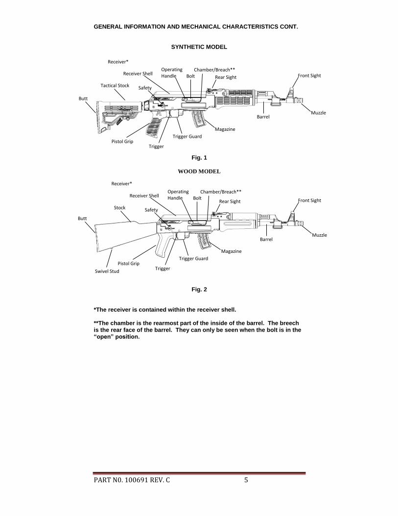
SYNTHETIC MODEL
Fig. 1
WOOD MODEL
Fig. 2
*The receiver is contained within the receiver shell. **The chamber is the rearmost part of the inside of the barrel. The breech is the rear face of the barrel. They can only be seen when the bolt is in the “open” position.
Trigger Guard
Trigger
Magazine
Pistol Grip
Tactical Stock Safety
Operating Handle Bolt
Chamber/Breach**
Rear Sight
Receiver*
Receiver Shell Front Sight
Muzzle Barrel
Trigger Guard
Trigger
Magazine
Pistol Grip
Stock Safety
Operating Handle
Chamber/Breach**
Rear Sight Receiver Shell
Front Sight
Muzzle Barrel
Bolt
Butt
Butt
Receiver*
Swivel Stud
PART N0. 100691 REV. C 6
Read and understand this entire manual and its safety warnings before firing the firearm.
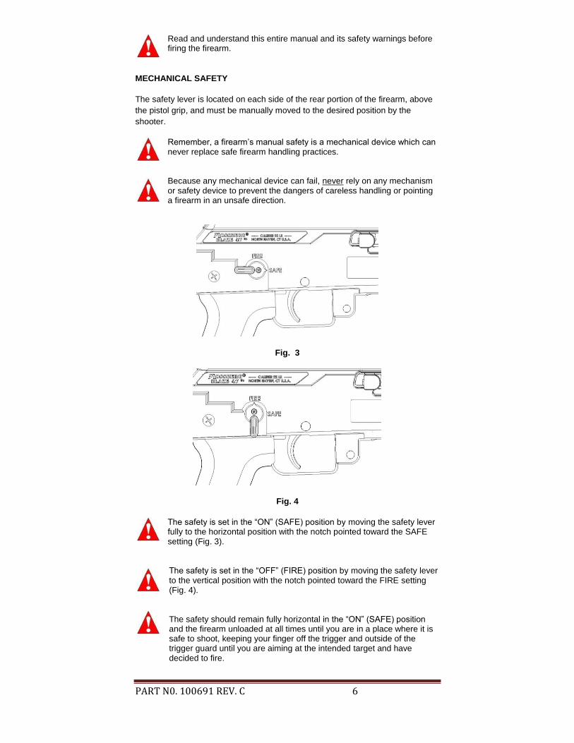
MECHANICAL SAFETY
The safety lever is located on each side of the rear portion of the firearm, above
the pistol grip, and must be manually moved to the desired position by the
shooter.
Remember, a firearm’s manual safety is a mechanical device which can never replace safe firearm handling practices.
Because any mechanical device can fail, never rely on any mechanism or safety device to prevent the dangers of careless handling or pointing a firearm in an unsafe direction.
Fig. 3
Fig. 4
The safety is set in the “ON” (SAFE) position by moving the safety lever fully to the horizontal position with the notch pointed toward the SAFE setting (Fig. 3).
The safety is set in the “OFF” (FIRE) position by moving the safety lever to the vertical position with the notch pointed toward the FIRE setting (Fig. 4).
The safety should remain fully horizontal in the “ON” (SAFE) position and the firearm unloaded at all times until you are in a place where it is safe to shoot, keeping your finger off the trigger and outside of the trigger guard until you are aiming at the intended target and have decided to fire.

PART N0. 100691 REV. C 7
KEEPING THE BOLT IN THE OPEN POSITION
Pull the operating handle fully rearward then push the handle inward, as
indicated by the ARROW on the back of the operating handle, to lock the bolt in
the open position (Fig. 5). To release the bolt, pull the end of the operating
handle outward and release. The bolt will then return to its forward closed
position.
Fig. 5
REMOVING THE MAGAZINE
WARNING
Removal of the magazine will not unload the firearm! Removing the magazine will not remove any cartridge which is in the firearm’s chamber! A cartridge in the firearm’s chamber can still be fired, even after the firearm’s magazine has been removed! After you remove the magazine always visually and physically inspect the chamber and receiver to ensure the firearm is completely unloaded!
FIREARM WILL FIRE WITH MAGAZINE REMOVED.
This firearm is equipped with a removable magazine. The magazine can be removed with the action in the open or closed position. Remove the magazine by pressing forward on the magazine latch (Fig. 6) while grasping and pulling the magazine downward. Familiarize yourself with the firearm by installing and removing an unloaded magazine and by learning to keep the action in the open
position.
Fig. 6
Press Magazine Latch Forward
ARROW

PART N0. 100691 REV. C 8
BEFORE LOADING THE FIREARM
Before loading, move the safety lever fully horizontal to the “ON” (SAFE)
position.
Before loading, with the bolt held in the open position by pulling the
operating handle fully rearward then pushing inward, as indicated by the
ARROW on the back of the operating handle, visually and physically
inspect the chamber and bore of the barrel for any obstruction,
excessive oil or grease. (The chamber is the rear portion of the barrel
which will contain the cartridge.) Obstructions of any kind can cause
damage to the firearm and could cause serious injury or death to you or
those around you.
During loading never allow fingers or any objects to contact the trigger.
Keep the muzzle pointed in a safe direction at all times.
Do not load firearm until ready for use! Unload firearm when shooting
has been completed! The safety lever should always be fully horizontal
in the “ON” (SAFE) position whether the firearm is loaded or not.
Check to be certain that the correct ammunition has been selected for use. Ensure it is the same caliber and type of cartridge as designated on the RIGHT side of the receiver shell.
This firearm is capable of firing a chambered cartridge with the magazine empty, without the magazine inserted, or if the magazine is dislodged from its locked position.
LOADING THE MAGAZINE
The magazine should be loaded before inserting it into the firearm. Remove it
from the firearm as described in “Removing the Magazine” section of this
manual.
Load the magazine by inserting one cartridge at a time, pressing against the
follower and fully rearwards until the cartridge is fixed between the “lips” (Fig. 7)
of the magazine. Repeat the operation until the magazine is full, or until the
desired number of cartridges have been loaded.
Blaze 47™ magazines have loading assist buttons (Fig. 7) on either side of the
magazine for user convenience and ease of loading. Pull the button(s) down
toward the base of the magazine to compress the spring for easier loading. The
magazine should be loaded with .22 Long Rifle cartridges only.
Fig. 7

PART N0. 100691 REV. C 9
LOADING THE FIREARM
Point the muzzle in a safe direction and ensure the safety lever is
positioned fully horizontal in the “ON” (SAFE) position. Lock the bolt in
the open position by pulling the operating handle fully rearward then
push the handle inward as indicated by the ARROW on the back of the
operating handle.
Insert a loaded magazine into the firearm by sliding the magazine up into the
magazine well until it is retained by the magazine latch (Fig. 8). Pull on the
magazine to make sure the magazine is firmly locked in place.
Release the bolt by pulling the operating handle outward and let the bolt return
freely to its forward position. The bolt will push one cartridge from the magazine
into the chamber. The firearm is now loaded.
If desired or necessary, the rifle can be single loaded with a cartridge directly into the chamber. Point the muzzle in a safe direction and ensure the safety lever is positioned fully horizontal in the “ON” (SAFE) position. Hold the bolt open by pulling the operating handle fully rearward then pushing inward, as indicated by the ARROW on the back of the operating handle, insert a cartridge directly into the chamber and close the bolt. It will be easier to single load the rifle if the magazine is removed from the rifle. The firearm is ready for firing as soon as the safety lever is moved vertical to the “OFF” (FIRE) position.
The firearm is now loaded and will fire if the trigger is pressed whether the magazine is in the firearm or not.
Fig. 8
To minimize the risk of unintended firing, the safety should remain fully horizontal in the “ON” (SAFE) position and the firearm unloaded at all times until you are in a place where it is safe to shoot, keeping your finger off the trigger and outside of the trigger guard until you are aiming at the intended target and have decided to fire.
UNLOADING THE FIREARM
Move the safety lever fully horizontal to the “ON” (SAFE) position. During unloading, never allow fingers or any other object to contact the trigger. KEEP THE MUZZLE POINTED IN A SAFE DIRECTION AT ALL TIMES.

PART N0. 100691 REV. C 10
Remove the magazine by pressing forward on the magazine latch while grasping
and pulling the magazine free. Using the operating handle, pull the bolt fully
rearward then push the handle inward as indicated by the ARROW on the back
of the operating handle to lock the bolt in the open position. This should extract a
loaded cartridge from the chamber.
After unloading always visually and physically inspect the chamber, receiver and magazine to make sure that all of the cartridges have been removed.
UNLOADING THE MAGAZINE
Hold the magazine in one hand, bottom down and front end forward. Push the cartridge forward and allow the nose of the cartridge to rise slightly upward until it is released from the magazine. Repeat until magazine is unloaded.
FIRING
Discharging firearms in poorly ventilated areas, cleaning firearms, or handling ammunition may result in exposure to lead and/or other substances known to cause birth defects, reproductive harm, and/or other serious physical injury. Have adequate ventilation at all times. Wash hands, face, and clothing thoroughly after exposure.
With the firearm pointed in a safe direction, held in the proper firing position, keep
your finger off the trigger and outside the trigger guard until you are aiming at the
intended target and have decided to fire. Move the safety lever vertical to the
“OFF” (FIRE) position. Once you intend to shoot, pulling the trigger through its
full travel to the rear will fire the firearm.
Upon firing, the pressure generated by the powder combustion will push the bolt
to its rearward position, extracting and ejecting the fired cartridge case. Upon
reaching its most rearward position, the bolt will have recocked the hammer and
the bolt recoil spring will then push the bolt forward, feeding a new cartridge from
the top of the magazine and chambering it. The firearm will again be ready to
fire.
As the firearm was designed to fire semi-automatically only, it is mandatory to
relieve pressure on the trigger after each shot in order to allow the disconnector
to again connect the trigger to the firing mechanism. This cycle will be repeated
every time the trigger is pulled until there are no cartridges remaining in the
magazine.
After the last cartridge has been fired the magazine follower is designed to keep
the bolt in the open position. If the magazine is removed from the firearm while
the bolt is kept open by the follower the bolt will close. If the firearm is fired
without a magazine, the bolt will not be held open and will need to be manually
locked open by pulling the operating handle fully rearward then pushing the
handle inward as indicated by the ARROW on the back of the operating handle.
To interrupt shooting and unload the firearm, keep the firearm pointed in a safe
direction, move the safety lever fully horizontal to the “ON” (SAFE) position,
remove the magazine and lock the bolt in the open position by pulling the
operating handle fully rearward then pushing the handle inward as indicated by
the ARROW on the back of the operating handle.

PART N0. 100691 REV. C 11
As a safety procedure, every time shooting is interrupted or the firearm is unloaded, move the safety lever fully horizontal to the “ON” (SAFE) position and pull the operating handle fully rearward, then push the handle inward as indicated by the ARROW on the back of the operating handle to lock the bolt in the open position. Always visually and physically inspect the chamber, receiver, and magazine to make sure that all of the cartridges have been removed. Should a cartridge fail to fire after pulling the trigger, move the safety lever fully horizontal to the “ON” (SAFE) position, keep the firearm pointed in a safe direction for at least 30 seconds in case of a “hangfire” (delayed firing of the cartridge after being struck by the firing pin). Then remove the magazine (as it may still have loaded cartridges), pull the operating handle fully rearward then push the handle inward as indicated by the ARROW on the back of the operating handle to lock the bolt in the open position and extract and eject the misfired cartridge. Segregate the misfired cartridge from other ammunition. Do not attempt to refire a misfired cartridge.
If at any time during firing, the sound of any given cartridge is noticeably louder or softer than previous cartridges fired, STOP! Do not load or fire additional cartridges until you have safely unloaded your firearm, moved the safety lever fully horizontal to the “ON” (SAFE) position and inspected it for possible damage or obstruction in the chamber or bore. (The bore is the inside surface of the barrel.) Firing the firearm with a bore obstruction can cause damage to the firearm and could cause serious injury or death to you or those around you.
If the need to inspect your firearm for possible damage or obstructions in the chamber or bore arises, keep the muzzle pointed in a safe direction. Remove the magazine (as it may still have loaded cartridges in it) while keeping the ejection port and magazine well opening of the firearm turned away from your face (to protect your eyes in the event a defective cartridge explodes). Pull the operating handle fully rearward then push the handle inward as indicated by the ARROW on the back of the operating handle to lock the bolt in the open position. Visually and physically inspect the chamber and receiver to make sure that all of the cartridges have been removed. After unloading, inspect your firearm for possible damage or obstructions in the chamber or bore. Each brand and type of ammunition can produce different accuracy results. It is best to try as many brands and types of ammunition as possible to determine which performs best in your firearm.
DISASSEMBLY
Move the safety lever fully horizontal to the “ON” (SAFE) position. Pull the operating handle fully rearward then push the handle inward as indicated by the ARROW on the back of the operating handle to lock the bolt in the open position. Visually and physically inspect the chamber, receiver, and magazine to make sure that all of the cartridges have been removed before disassembling the firearm. Always wear eye protection during disassembly and cleaning.
During disassembly/reassembly reference the “Exploded View” section of this
manual for labeled and listed parts contained within this firearm.

PART N0. 100691 REV. C 12
Remove the ten #4 Plastite™ screws, the front sight set screw (use a 3/32 hex
key), and the two sets of barrel nuts and machine screws from the LEFT half of
the receiver shell (Fig. 9). When removing the machine screw from the barrel
nut, place your thumb on the screw head on the opposite side of the receiver
shell to keep it from rotating as you unscrew them. The stock fasteners consist of
two parts, a barrel nut and a machine screw.
Fig. 9
Remove the front sight and forend holder by sliding them forward off the barrel.
Then remove the upper and lower forends by rotating the front ends away from
the barrel and pull them away from the receiver shell (Fig. 10).
Fig. 10
Remove the pistol grip bolt, allowing the pistol grip to be pulled away from the
receiver shell, and pull the stock away from the receiver shell (Fig. 11).
Fig. 11
Barrel Nut and
Machine Screw
Barrel Nut and
Machine Screw
Front Sight Set Screw

PART N0. 100691 REV. C 13
Remove the rear sight from the top of the receiver shell by rotating the elevation
adjustment knob counterclockwise until the knob can be removed (Fig. 12a).
Then rotate the rear of the sight upward to expose the two #4 Plastite™ screws
holding the sight in place. Remove the sight spring which is over the rear screw
(Fig. 12b). Remove the 2 screws. When reassembling, take care not to over
tighten screws.
Fig. 12a Fig. 12b
Confirm that the safety lever is fully horizontal in the “ON” (SAFE) position with
the notch pointing toward the SAFE position. Then remove the #4 Plastite™
screw from the safety lever on the RIGHT side of the receiver shell and pull the
safety lever away from the LEFT side of the receiver shell; (Fig. 13a). Next, pull
the safety lever away from the receiver shell; the safety barrel will remain
attached to the safety lever by the #4 Plastite™ screw on the left side safety
lever (Fig 13b).
Fig. 13a Fig. 13b
Separate the left and right receiver shells from one another and remove the
action assembly (Fig. 14).
Fig. 14
Elevation Adjustment Knob
Screw with spring

PART N0. 100691 REV. C 14
Remove the bolt cover assembly from the action assembly. (Lift the back end up
and then pull it away from the receiver (Fig. 15).)
Fig. 15
Do not dislodge the disconnector spring from the internal components.
Doing so will result in the firearm failing to function properly.
Do not pull the trigger when the firearm is disassembled, doing so can cause
damage to the internal components.
At this point no further disassembly of the receiver should be performed. The
screws in the receiver are covered with white security sealant to show that
disassembly should not continue beyond this point. If any service is required to
the receiver, return the entire firearm to the Product Service Center or to a
qualified gunsmith (refer to the “Service Instructions” section of this manual).
Place your thumb over the front face of the bolt then release the bolt by pulling
the operating handle outward and slowly guide the bolt back to its forward
position using your thumb. Allow the bolt to angle downwards out of the bolt
cover until you are able to lift the operating handle free from the bolt. Continue to
angle the bolt out of the bolt cover until you are able to remove the bolt, recoil
spring, and recoil rod from the bolt cover (Fig. 16).
Fig. 16
Receiver
Disconnector Spring
Bolt Cover Assembly

PART N0. 100691 REV. C 15
Slide the recoil spring and recoil rod free from the bolt and each other (Fig. 17).
Fig. 17
Remove the barrel by removing the two barrel retainer screws (use a 5/32 hex
key) and the barrel retainer (Fig. 18). The barrel can now be removed from the
receiver.
Fig. 18
CLEANING AND LUBRICATION
Note: Semi-automatic firearms require more frequent cleaning than those that
are manually operated.
With proper maintenance and care, your firearm will provide you with years of
dependable service. Your firearm should be inspected and cleaned after every
200 rounds to ensure that it remains in good condition. However, unusually
dusty, dirty, or harsh weather conditions, or use of dirty ammunition which leaves
significant powder residue may necessitate more frequent cleaning.
Clean and lubricate your firearm as soon as possible after use. This is especially
important if your firearm has been exposed to moisture. For maximum
performance and continued satisfaction with your firearm, periodic cleaning and
lubrication are essential. Always wear eye protection during cleaning and
lubrication.
Use the instructions and equipment provided with a quality firearm cleaning kit.
All metal parts should be cleaned with firearm solvent and lightly lubricated with
firearm oil. Over-lubrication should be avoided. Use only lubricants specifically
designed for firearms. Avoid the use of abrasives which may damage the metal
finish.

PART N0. 100691 REV. C 16
Normal use requires only that the mechanisms be free of excessive shooting
residue. Very little lubrication other than a light oiling of external metal surfaces
is needed to prevent rust.
If the firearm is to be stored for a long period of time it should be thoroughly
cleaned and oiled to prevent rusting. Do not plug barrel or store in a fabric lined
case that will absorb lubricant from the firearm.
THE BOLT ASSEMBLY AND RECEIVER
In the receiver, special attention should be given to the bolt sliding surfaces. The
bolt and the receiver must be carefully cleaned and free of any solid residues.
Solid residues in the bolt/receiver areas may prevent the bolt from closing
properly and the firearm may fail to fire.
THE BARREL
Whenever possible, use cleaning products that allow cleaning the bore from
breech to muzzle. If this is not possible, be very careful while introducing the
cleaning rod into the barrel muzzle, thus avoiding any damage to the barrel
crown (where the rifling comes to an end at the muzzle).
Using a .22 caliber brass cleaning brush moistened with solvent, scrub the bore
several times.
Use a .22 caliber cleaning rod with a clean cloth to wipe the bore dry. Repeat
several times using a new patch each time until the barrel is clean and shows no
signs of residue.
Finally, wipe with a patch moistened with a quality gun oil. Do not over-lubricate,
a light film is recommended.
If during the disassembly or cleaning of your firearm you should detect any cracks, fractures, chips, or excessive wear, do not use your firearm until you have contacted the Product Service Center or a qualified gunsmith. Using broken or worn parts may result in damage to the firearm and could cause serious injury or death to you or those around you.
Make sure the bore and receiver are free of obstructions and excessive lubricant after cleaning. Be sure not to leave cleaning patches or excessive oil or grease in the bore as they can create dangerous obstructions. Obstructions of any kind can cause damage to the firearm and could cause serious injury or death to you or those around you.
Camouflage firearms: Caution should be exercised to avoid exposure of camouflage patterns to solvents or insect repellants.

PART N0. 100691 REV. C 17
REASSEMBLY
Slide the chamber end of the barrel into the receiver, orienting the front sight
upwards. Install the barrel retainer by sliding it into its groove on the bottom of
the barrel then install the barrel retainer nuts and screws (use a 5/32 hex key)
until they are snug and then tighten a quarter turn (Do not over tighten) (Fig. 19).
Fig. 19
Insert the recoil spring into the hole in the back of the bolt and then insert the
recoil rod into the recoil spring (Fig. 20).
Fig. 20
Insert the bolt, recoil spring, and recoil rod into the bolt cover by first inserting the
recoil rod into the small hole in the back interior portion of the bolt cover. Once
the recoil rod is securely located in the small hole, push the bolt in at an angle
similar to Figure 16 below, compressing the recoil spring. Insert the operating
handle into the bolt with the arrow facing rearwards (Fig 21).
Fig. 21
Hole to insert Recoil Rod

PART N0. 100691 REV. C 18
Press the bolt against the top of the inside of the bolt cover, then pull the
operating handle fully rearwards then push the handle inwards as indicated by
the ARROW on the back of the operating handle to lock the bolt in the open
position (Fig. 22).
Fig. 22
Install the bolt cover assembly to the receiver by first sliding the front of the bolt
cover over the chamber area of the receiver, then press the rear of the bolt cover
down (Fig. 23). Make sure that the safety button on the back of the action
assembly is fully rearward in the “ON” (SAFE) position.
Fig. 23
Safety Button

PART N0. 100691 REV. C 19
Insert this completed action assembly into the RIGHT half of the receiver shell
(the RIGHT half has the ejection port) (Fig. 24a). Place the threaded insert into
the receiver shell (Fig. 24b). Then attach the LEFT half of the receiver shell
encasing the action assembly and the threaded insert.
Fig. 24a
Fig. 24b
Install the ten #4 Plastite™ screws into the receiver shell. Tighten the Plastite™
screws until snug (Fig. 25). Do not over tighten.
Fig. 25
Insert the safety lever with the safety barrel attached into the LEFT side of the
receiver shell, with the notch facing the “ON” (SAFE) position (Fig. 26a). Then on
the RIGHT side of the receiver shell insert the safety lever into the receiver shell,
then screw in the #4 Plastite™ screw (Fig 26b). Tighten the Plastite™ screws
until snug. Do not over tighten.
Fig. 26a Fig. 26b
Right Half of Receiver Shell
Action Assembly
Threaded Insert

PART N0. 100691 REV. C 20
Attach the rear sight to the top of the receiver shell, screwing in the two #4
Plastite™ screws that hold the sight in place and placing the sight spring on the
rear screw (Fig. 27a). Then rotate the sight downwards, retaining the spring
between the screw and the cut out and attach the elevation adjustment knob by
screwing it on clockwise until the sight is at a desirable height (Fig. 27a).
Fig. 27a Fig. 27b
Attach the pistol grip and secure it in place with the pistol grip bolt, tightening the
bolt until snug (do not over tighten). Insert the stock into the receiver shell (Fig.
28, Fig. 30). The stock fasteners consist of two parts, a barrel nut and a machine
screw. Insert the barrel nut through the hole on the RIGHT side of the receiver
shell and use the machine screw to secure it on the other side. When attaching
the stock fasteners, place your thumb on the screw head on the opposite side of
the receiver shell to keep it from rotating as you screw it in.
Fig. 28
Elevation Adjustment Knob
Screw with spring
Spring Cut Out

PART N0. 100691 REV. C 21
Attach the upper and lower forends by inserting the back ends in at an angle,
clipping them into the receiver shells and then rotating the front ends toward the
barrel. Insert the forend holder over the barrel and line the hole on it up with the
one on the receiver shell. The bolt to attach the forend parts consists of two
parts, a barrel nut and a machine screw. Insert the barrel nut through the hole
and use the machine screw to secure it on the other side (both parts can be
inserted from either side). When attaching the barrel nut and machine screw,
place your thumb on the screw head on the opposite side of the receiver shell to
keep it from rotating as you screw it in. (Fig. 29).
Fig. 29
Then slide the front sight onto the barrel with the sight orientated upwards, attach
with the front sight set screw (Fig. 30)
Fig. 30
Hole Hole
Barrel Nut and
Machine Screw
Barrel Nut and
Machine Screw
Front Sight Set Screw
PART N0. 100691 REV. C 22
FUNCTION TESTING
Check your firearm for proper functioning before loading or firing live ammunition.
Move the safety lever fully horizontal to the “ON” (SAFE) position.
Be sure the firearm is completely unloaded by opening the action, removing the magazine and visually and physically inspecting the chamber, receiver and magazine to make sure that all of the cartridges have been removed. Keep the firearm pointed in a safe direction at all times.
Open and close the action several times to check for free movement of the action
assembly.
Close the action and leave the safety lever fully horizontal in the “ON” (SAFE)
position. Make certain the firearm is pointed in a safe direction. Pull the trigger
fully rearward. The hammer should not release.
Remove your finger from the trigger. Move the safety lever vertical to the “OFF”
(FIRE) position. The hammer should not release.
Leave the safety lever in the “OFF” (FIRE) position. Make certain the firearm is
pointed in a safe direction. Pull the trigger fully rearward. THE HAMMER
SHOULD RELEASE.
When you have completed the function testing, lock the action in the open
position by pulling the operating handle fully rearward, then push the handle
inward, as indicated by the ARROW on the back of the operating handle, and
move the safety lever fully horizontal to the “ON” (SAFE) position.
IF YOUR FIREARM DOES NOT PERFORM AS DESCRIBED IN ANY OF THE PREVIOUS STEPS, CONTACT THE FACTORY AUTHORIZED PRODUCT SERVICE CENTER IMMEDIATELY. DO NOT ATTEMPT TO USE THE FIREARM.
Firearms are complicated mechanisms. Any modification, alterations, or improper fitting of parts may result in a dangerous malfunction, damage to the firearm and could cause serious injury or death to you or those around you. The firearm’s owner must accept full responsibility for the correct reassembly and functioning of the firearm after any disassembly or replacement of parts.
PERIODICALLY CHECK THAT THE MUZZLE BRAKE (IF SO EQUIPPED) IS TIGHTENED FIRMLY ONTO THE BARREL.

PART N0. 100691 REV. C 23
PRECAUTIONS AND CARE WITH YOUR FIREARM
When you store your firearm, make sure that the magazine and the chamber are empty. Visually and physically inspect the chamber, receiver and magazine to make sure that all of the cartridges have been removed. Operation of the firearm and/or repeated disassembly may cause screws to loosen. Refer to the section of the manual entitled “Reassembly” and check all screws including the #4 Plastite™ screws periodically and at each cleaning interval to ensure the continued accuracy and safe operation of your firearm. Care should be taken not to over-tighten any screws as this may cause screws to strip.
Handling leaves moisture prints that can cause metal parts to rust. Abrupt
changes in temperature cause condensation and moisture. Wipe the barrel and
other metal parts with light oil after handling.
SIGHT ADJUSTMENTS
Before making any sight adjustments move the safety lever fully horizontal to the “ON” (SAFE) position and keep the muzzle pointed in a safe direction. Lock the action in the open position by pulling the operating handle fully rearward, then push the handle inward, as indicated by the ARROW on the back of the operating handle, remove the magazine and visually and physically inspect the chamber and inside the receiver to make sure that all cartridges have been removed.
Elevation adjustment: To raise the point of impact, rotate the elevation
adjustment knob counterclockwise. To lower the point of impact, rotate the
elevation adjustment knob clockwise.
Fig. 31
Windage adjustment: To move the point of impact to the right, rotate the
windage adjustment knob clockwise. To move the point of impact to the left,
rotate the windage adjustment knob counterclockwise.
Elevation Adjustment Knob
Windage Adjustment Knob

PART N0. 100691 REV. C 24
Should your firearm or any component of your firearm require service, ship your
entire firearm (please do not send components only), via your chosen carrier,
postage paid (we do not accept C.O.D. shipments), following these instructions:
● Make absolutely certain your firearm is unloaded.
● Do not send ammunition with your firearm.
● Remove all accessories from your firearm such as scopes, slings,
scope mounts, etc.
● Ship your firearm in a suitable container, packaging it securely to
prevent parts from shifting and/or damage during shipping.
● Include a note with a clear description of the service you wish us to
perform, your complete return shipping address (no P.O. boxes
please), your daytime telephone number and your e-mail address (if
available). It is advisable to place your correspondence inside your
shipping container when shipping.
SHIPPING ADDRESS
Product Service Center
Maverick Arms, Inc.
1001 Industrial Blvd.
Eagle Pass, TX 78853
If you have any service related questions, please contact the Product
Service Center at (830) 773-9007 or [email protected]
TO ORDER PARTS
To order parts from the Product Service Center, you can fax, phone,
mail, or e-mail your order to one of the below numbers/addresses.
Fax Number: (830) 773-5893
Phone Number: (830) 773-9007
E-mail Address: [email protected]
Mailing Address: Product Service Center
Maverick Arms, Inc.
1001 Industrial Blvd.
Eagle Pass, TX 78853
Attn: Order Department
Please provide your name, address, city, state, zip, your daytime phone number
and e-mail (if available). The Product Service Center will need the Model
Number, Serial Number, Gauge/Caliber, Finish, Item Number, and Part Name.
There is a $7.50 (U.S.) minimum parts order charge. Most major credit cards,
money orders, and bank drafts are accepted.
Service outside of the U.S.A.
For Mossberg firearm parts and service requirements outside of the United
States, customers are requested to contact the closest Mossberg stocking
dealer/distributor.
PART N0. 100691 REV. C 25
MOSSBERG® WARRANTY
MOSSBERG BLAZE 47™
TWO (2) YEAR LIMITED WARRANTY
Limited Warranty: O.F. Mossberg & Sons, Inc. (“Mossberg”) warrants to you, the original retail purchaser of a new Mossberg BLAZE 47™ (the “Mossberg firearm”), that the Mossberg firearm will be free of defects in material or manufacture for a period of two (2) years from the date of your purchase of the new Mossberg firearm (the “Warranty Period”) in the United States or Canada. This is the only express warranty on the Mossberg firearm. MOSSBERG MAKES NO OTHER WARRANTIES OF ANY KIND OR CONDITIONS, INCLUDING, BUT NOT LIMITED TO ANY IMPLIED WARRANTY OF MERCHANTABILITY OR FITNESS FOR A PARTICULAR PURPOSE. This Limited Warranty gives you specific legal rights, and you may have other rights that vary from State to State. Purchaser’s Remedy: During the Warranty Period, Mossberg will, at its sole option, (1) repair the Mossberg firearm or any part thereof that, upon examination and testing by Mossberg, does not conform to the Limited Warranty without charge to you for parts or labor, or (2) replace the Mossberg firearm with a new or similar model. THIS REMEDY SHALL BE YOUR EXCLUSIVE AND SOLE REMEDY FOR ANY BREACH OF WARRANTY. MOSSBERG SHALL NOT BE RESPONSIBLE FOR ANY OTHER EXPENSES, LOSSES OR INCONVENIENCE THAT YOU MAY SUSTAIN AS A RESULT OF THE PURCHASE, USE, MALFUNCTION OR DEFECTIVE CONDITION OF THE MOSSBERG FIREARM. Mossberg reserves the right to inspect, examine and/or test the Mossberg firearm to assess any claim made under the Limited Warranty.
EXCLUSIONS: THIS WARRANTY DOES NOT COVER THE COSMETIC APPEARANCE OF THE MOSSBERG FIREARM OR ANY DAMAGE CAUSED BY: (1) NORMAL WEAR AND TEAR; (2) FAILURE TO PERFORM PROPER CARE AND MAINTENANCE; (3) ACCIDENTS, ABUSE OR NEGLECT; (4) BARREL OR BORE OBSTRUCTIONS; (5) FAILURE TO FOLLOW THE INSTRUCTIONS AND WARNINGS THAT ACCOMPANY THE
MOSSBERG FIREARM; OR (6) THE USE OF DEFECTIVE, NON-SAAMI STANDARD, REMANUFACTURED,
HANDLOADED, AND/OR RELOADED AMMUNITION. IN ADDITION, ANY UNAUTHORIZED REPAIRS, ALTERATIONS OR MODIFICATIONS TO THE MOSSBERG FIREARM WILL AUTOMATICALLY VOID THE LIMITED WARRANTY.
LIMITATION OF DAMAGES: EXCEPT WHERE PROHIBITED BY LAW, MOSSBERG WILL NOT BE LIABLE FOR ANY LOSS OR DAMAGE WHATSOEVER ARISING FROM THE USE OF THIS MOSSBERG FIREARM, WHETHER DIRECT, INDIRECT, SPECIAL, INCIDENTAL, CONSEQUENTIAL OR PUNITIVE, REGARDLESS OF THE LEGAL THEORY ASSERTED, INCLUDING CONTRACT, WARRANTY, NEGLIGENCE, OR STRICT LIABILITY. SOME JURISDICTIONS DO NOT ALLOW LIMITATIONS ON HOW LONG AN IMPLIED WARRANTY LASTS, OR THE EXCLUSION OF INCIDENTAL OR CONSEQUENTIAL DAMAGES, SO THE ABOVE LIMITATIONS MAY NOT APPLY TO YOU. Warranty Service: To obtain service under this Limited Warranty, you must follow the instructions found in the “Service Instructions” section of the Owner’s Manual and return the Mossberg firearm to the authorized Product Service Center. You are responsible for all shipping costs to the Product Service Center. Mossberg will not accept COD shipments of any Mossberg firearm for service. After repair or replacement, the Mossberg firearm or a similar model will be returned to you, return postage paid by Mossberg. If we replace the Mossberg firearm, we will keep the firearm that you returned to Mossberg. Modification of Warranty: No agent, representative, distributor, or authorized dealer of Mossberg firearms has any authority to modify the terms or conditions of the Limited Warranty in any way. The Limited Warranty may only be modified in writing by an authorized officer of Mossberg. THIS LIMITED WARRANTY IS EFFECTIVE JANUARY 1, 2014.

PART N0. 100691 REV. C 26
EXPLODED VIEW SYNTHETIC MODEL

PART N0. 100691 REV. C 27
EXPLODED VIEW WOOD MODEL

PART N0. 100691 REV. C 28

PART N0. 100691 REV. C 29

PART N0. 100691 REV. C 30

PART N0. 100691 REV. C 31

PART N0. 100691 REV. C 32