OWNERS MANUAL Model No. - Agri-Fab · Rear wheel weights and tire chains are required to provide...
36
Model No. LST42D OWNERS MANUAL PRINTED IN U.S.A. FORM NO. 42320 (06/16/11) CAUTION: Read Rules for Safe Operation and Instructions Carefully • Safety • Assembly • Operation • Maintenance • Parts 42" SNOW THROWER the fastest way to purchase parts www.speedepart.com ™
-
Upload
duongkhanh -
Category
Documents
-
view
213 -
download
1
Transcript of OWNERS MANUAL Model No. - Agri-Fab · Rear wheel weights and tire chains are required to provide...

Model No.LST42D
OWNERSMANUAL
PRINTED IN U.S.A. FORM NO. 42320 (06/16/11)
CAUTION:Read Rules for Safe Operation
and Instructions Carefully
• Safety• Assembly• Operation• Maintenance• Parts
42" SNOW THROWER
the fastest way to purchase parts www.speedepart.com
™

2
TABLE OF CONTENTS
ACCESSORIES ....................................................................................................................................................................2SAFETY RULES ...................................................................................................................................................................3FULL SIZE HARDWARE CHART .........................................................................................................................................4CARTON CONTENTS ..........................................................................................................................................................6ASSEMBLY ...........................................................................................................................................................................7OPERATION .......................................................................................................................................................................25MAINTENANCE .................................................................................................................................................................26SERVICE AND ADJUSTMENTS ........................................................................................................................................27STORAGE ..........................................................................................................................................................................28TROUBLESHOOTING ........................................................................................................................................................28REPAIR PARTS ILLUSTRATION .............................................................................................................................30,32,34REPAIR PARTS LIST................................................................................................................................................31,33,34SLOPE GUIDE ...................................................................................................................................................................35PARTS ORDERING/SERVICE ........................................................................................................................BACK COVER
IMPORTANT:Rear wheel weights and tire chains are required to provide extra traction and stabilitywhenusingthissnowthrowerattachment.Theseitemsareavailablewhere you purchased your tractor.
WHEEL WEIGHTS TIRE CHAINS

3
SAFETY
Readandunderstandtheoperatinginstructionsbeforeusing.
Keeptheareaofoperationclearofallpersons,especiallysmallchildrenandpets.Thoroughlyinspecttheareatobeclearedandremovealldoormats,sleds,boards,wiresandotherforeignobjects.Useextremecautionwhenoperatingonorcrossinggravelsurfaces.Neverdirectdischargeatbystandersorallowanyoneinfrontofthesnow thrower.
Do not place hands near rotating parts. Keep clear of the dischargeopeningatalltimes.
Do not place feet near rotating parts.
• Neverallowchildrentooperatetheequipment.• Neverallowadultstooperatetheequipmentwithout
proper instruction.• Disengageallclutchesandshiftintoneutralbefore
starting engine.• Donotoperateequipmentwithoutwearingadequatewinteroutergarments.
• Wearsubstantialfootwearwhichwillprotectfeetandimprovefootingonslipperysurfaces.
• Checkfuelbeforestartingtheengine.Donotremovethefuelcaporfillthefueltankwhiletheengineisrunningorhot.Donotfillthefueltankindoors.Gasolineisanextremelyflammablefuel.
• Makesurethesnowthrowerheightisadjustedtoclearthetypesurfaceitwillbeusedon.
• Donotusethesnowthrowerwithoutwheelweightsattached to the tractor.
• Nevermakeanyadjustmentswhiletheengineisrunning.
• Alwayswearsafetyglassesoreyeshieldduringoperationorwhileperformingadjustmentorrepair.
• Donotplacehandsorfeetnearrotatingparts.Keepclearofthedischargeopeningatalltimes.
• Donotcarrypassengers.• Afterstrikingaforeignobject,stoptheengine,removethewirefromthesparkplugandthenthoroughlyinspectthesnowthrowerfordamage.Repairanydamagebeforerestartingandoperatingthesnowthrower.
• Ifthesnowthrowerstartstovibrateabnormally,stoptheengineimmediatelyandcheckforthecause.Vibrationisgenerallyawarningoftrouble.
• Stoptheenginewheneveryouleavetheoperatingposition,beforeuncloggingthesnowthrowerormakinganyadjustmentsorinspections.
• Takeallpossibleprecautionswhenleavingtheunitunattended.Disengagetheattachmentclutchleverorswitch, lower the snow thrower, shift into neutral, set theparkingbrake,stoptheengineandremovethekey.
• Whencleaning,repairingorinspecting,makecertainallmovingpartshavestopped.Disconnectthesparkplugwireandkeepitawayfromtheplugtopreventaccidental starting.
• Donotrunengineindoorsexceptwhentransportingthesnowthrowerinoroutofthebuilding.Opentheoutsidedoors.Exhaustfumesaredangerous.
• Donotclearsnowacrossthefaceofslopes.Exerciseextremecautionwhenchangingdirectiononslopes.Donotattempttoclearsteepslopes.Refertotheslopeguideonpage35ofthismanual.
• Neveroperatethesnowthrowerwithoutguards,plates or other safety protection devices in place.
• Neveroperatethesnowthrowernearglassenclosures,automobiles,windowwells,dropoffsetc.withoutproperadjustmentofthesnowthrowerdischarge angle.
• Neverrunthesnowthrowerintosnowathighspeeds.• Donotoverloadthesnowthrowercapacitybyattemptingtoclearsnowattoofastarate.
• Neveroperatethesnowthrowerathightransportspeedonslipperysurfaces.Lookbehindandusecarewhenbackingup.
• Watchfortrafficandstayalertwhencrossingoroperating near roadways.
• Disengagepowertothesnowthrowerwhentransporting or when not in use.
• Useonlyattachmentsandaccessoriesapprovedbythemanufacturerofthesnowthrower(suchaswheelweights,counterweights,cabsetc.)
• Neveroperatethesnowthrowerwithoutgoodvisibility.
184045
199683199682
4
EB D G
H I K
O
F
X
UY
C
W
L
Q
S,TR
Z
KK
EE
N
CCBB
AA
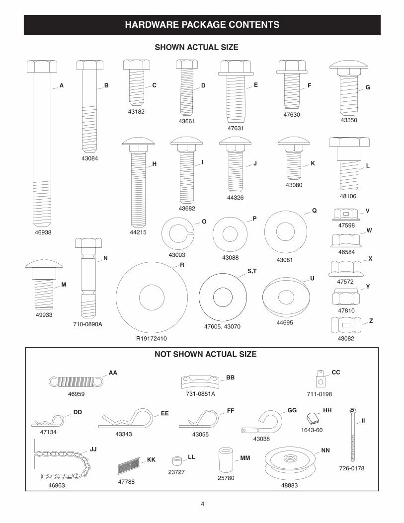
NOT SHOWN ACTUAL SIZE
SHOWN ACTUAL SIZE
DD
M
J
JJ
FF GG
II
VP
HH
A
LL NN
MM
46938
43084
43182
4366147631
4763043350
44215
43682
44326
43080
48106
49933
710-0890A
43003 43088 43081
R19172410
47605, 4307044695
43082
47810
47572
46584
47598
46959 731-0851A 711-0198
4305543038
1643-60
23727
46963
726-0178
47788
47134 43343
4888325780
HARDWARE PACKAGE CONTENTS

5
REF. QTY. DESCRIPTION REF. QTY. DESCRIPTION
U 2 Bowed Washer V 6 Flanged Nut, 1/4" W 1 Flanged Nut, 5/16" X 10 Flanged Nut, 3/8" Y 17 NylockNut,5/16"(2spareparts) Z 2 HexLockNut,3/8" AA 1 Spring BB 3 Chute Keeper CC 1 Trunnion DD 2 Hairpin Cotter, 5/64" EE 4 Hairpin Cotter, 1/8" FF 1 Hairpin Cotter, 3/32" GG 2 LockPin HH 1 Plastic Cap II 2 Nylon Tie JJ 2 Chain, Tensioning KK 2 TailReflector LL 1 SmallSpacer MM 1 Large Spacer NN 1 Pulley
A 1 Hex Bolt, 3/8" x 3-1/4" B 2 Hex Bolt, 5/16" x 1-3/4" C 4 Hex Bolt, 5/16" x 3/4" D 6 Hex Bolt, 1/4" x 1" E 6 HexBolt,3/8"x1"(ThreadForming) F 2 HexBolt,5/16"x3/4"(ThreadForming) G 6 Carriage Bolt, 3/8" x 1" H 2 Carriage Bolt, 5/16" x 1-3/4" I 2 Carriage Bolt , 5/16" x 1-1/4" J 4 Carriage Bolt, 5/16" x 1" K 2 Carriage Bolt, 5/16" x 3/4" L 4 Shoulder Bolt M 2 Shoulder Bolt N 2 Shear Bolt (spare parts) O 7 LockWasher,3/8" P 7 Washer, 1/4" Q 6 Washer, 5/16" R 8 Washer, 1/2" S 1 Washer, 3/8" (Thin) T 3 Washer, 3/8"

6
CARTON CONTENTS
1. SuspensionArms(2)2. Left Hand Side Plate3. Right Hand Side Plate4. Anti-rotationBracket5. EngagementRod(Notusedonsomemodels)6. EnginePulleyKeeper(Notusedonsomemodels)7. ChuteCrankRodAssembly8. SupportTube,CrankRod9. LiftHandleandCable10. CableBracket
11. L.H.HangerBracket(OutsideMounting)12. R.H.HangerBracket(OutsideMounting)13. ClutchIdlerAssembly14. V-Belt, Drive (Short) #4698915 V-Belt, Drive (Long) #4813816. V-Belt,Auger(AttachedtoHousingAssembly)17. ChuteandControlCableAssembly18. HousingAssembly19. L.H.HangerBracket(InsideMounting)20. R.H.HangerBracket(InsideMounting) HardwarePackage(StoredinsidePlasticKeg)
14
12 4 5
6
12
9
8
10
2019
11
17
16
15
18
13
7
3
47043
46948
24558
6545065367
2439425678
25679
6445264451
46989
48138
47846

7
• Removeallpartsandhardwarepackagesfromthecarton. Lay out parts and hardware and identify using the illustrations on pages 4 and 6.
NOTE:Notallofthesuppliedpartsandhardwarewillbeneededforyourparticulartractor.Unneededitemsmaybediscardedafteryouhavecompletedassemblyandcheckedoperationofunit.DO NOT DISCARD the two spareshearbolts(N)and5/16"nylocknuts(Y).RefertotheServiceandAdjustmentssectiononpage27.
REMOVAL OF PARTS FROM CARTON
TOOLS REQUIRED FOR ASSEMBLY
(2) 7/16" Wrenches(2) 1/2" Wrenches(2) 9/16" Wrenches(2) 3/4" Wrenches(1) Screw Driver(1) Knife
ADDITIONAL ITEMS REQUIREDGeneral Purpose Grease
TRACTOR PREPARATION
Beforeperformingtheseinstructions,refertotheServiceandAdjustmentssectionofyourtractorowner'smanualforspecificsafetyinstructions.
• Allowengine,mufflerandexhaustdeflectortocoolbeforebeginning.
• Removeanyfrontorrearattachmentwhichismountedtoyourtractor.
• Removethemowerdeck.Refertoyourtractorowner'smanualforremovalinstructions.Markallloosepartsandsaveforreassembly.
• Removethetractorhood.Refertoyourtractorowner'smanualforremovalinstructions.
CAUTION: Before starting to assemblethesnowthrower,removethesparkplugwire(s),set theparkingbrakeand remove thekeyfromthetractorignition.
FIGURE 2 RIGHT SIDE VIEW
IMPORTANT: Right hand (R.H.) and left hand (L.H.) side ofthetractoraredeterminedfromtheoperatorspositionwhile seated on the tractor.
REMOVE FRONT SCREWS
REMOVE BROWNING SHIELD
MOWER DECK SUSPENSION
BRACKET
FIGURE 1
INSTRUCTIONS FOR TRACTORS WITH SINGLE FRONT DECK SUSPENSION BRACKET
STEP 2: (SEE FIGURE 2)• Removethebrowningshieldfromthefrontofthetractorasshown.Holdontotheshieldasyouremovethesecondscrewtopreventitfromfalling.
• Besuretoreinstallthebrowningshieldwhensoinstructed in step 3.
IDENTIFY YOU TRACTOR
STEP 1: (SEE FIGURE 1)• Lookunderthefrontofyourtractor.Ifthereisasinglemowerdecksuspensionbracketlocatedunderneaththemiddleofthefrontaxle,continueontostep2. If your tractor does not have a mower deck suspension bracket underneath the middle of the front axle, skip to step 21 on page 13 for tractors withdualsuspensionbrackets.
ASSEMBLY

8
STEP 4: (SEE FIGURE 4)• Assembleashoulderbolt(L)anda3/8"washer(T)to
the outside of R.H. side plate, securing it with a 3/8" flangednut(X).RepeatforL.H.sideplate.
FIGURE 4 RIGHT SIDE VIEW
FIGURE 3 RIGHT SIDE VIEW
5/16"NYLOCKNUT (Y)
5/16" x 1"CARRIAGE BOLT (J)
ENGINE MOUNTING PLATE
(4) 1/2" WASHERS (R)
(3) 3/8" FLANGE NUTS (X)
(3) 3/8" x 1"CARRIAGEBOLTS (G)
SEE NOTE
3/8" WASHER (T)
SHOULDER BOLT (L)
3/8" FLANGEDNUT (X)
INSTALL SIDE PLATES
STEP 3: (SEE FIGURE 3)• FastentheR.H.SidePlate(bendfacingout)tothefrontthreeholesinthetractorframeusingthree3/8"x1"carriagebolts(G),three1/2"washers(R)(seenote)andthree3/8"flangenuts(X). For the rear hole, usea5/16"x1"carriagebolt(J),a1/2"washer(R)anda5/16"nylocknut(Y). Place the 1/2" washers (R) betweenthetractorframeandthesideplate.Repeatfor L.H. side plate.
• Reinstallthebrowningshieldontothetractorframeusing the original screws.
NOTE:Ifthereisanenginemountingplate(shownwithdottedlines)leavethe1/2washerofftheboltthatgoesthrough the plate.
INSTALL HANGER BRACKETS AND SHOULDER BOLTS TO OUTSIDE OF FRAME
STEP 5: (SEE FIGURE 5)• Removethebolt,ifpresent,intheholedirectlybehindthebrakerodontheleftsideofthetractorframe.
• AttachtheL.H.HangerBracket(tubefacingout)totheholeusinga5/16"x3/4"selfthreadingbolt(F).
• Installaroundheadshoulderbolt(M)intotheholethatis9-1/2"totherearoftheboltyoujustinstalled.Secureitwitha3/8"flangenut(X)ontheinsideoftheframe.
FIGURE 5 LEFT SIDE VIEW
5/16" x 3/4" SELFTHREADING BOLT (F)
L.H. HANGERBRACKET
BRAKE ROD
3/8" FLANGEDNUT (X)
SHOULDERBOLT (M)
5/16" x 3/4" SELFTHREADING BOLT (F)
R.H. HANGERBRACKET
RIGHT END OFBRAKE ROD
3/8" FLANGEDNUT (X)
SHOULDERBOLT (M)
STEP 6: (SEE FIGURE 6)• Removethebracket,ifpresent,fromtheholedirectlybehindtheendofthebrakerodontherightsideofthetractorframe.Storethebracketandbolt.
• AttachtheR.H.HangerBrackettotheholeusinga5/16"x3/4"selfthreadingbolt(F).
• Installaroundheadshoulderbolt(M)intotheholethatis9-1/2"totherearoftheboltyoujustinstalled.Secureitwitha3/8"flangenut(X)ontheinsideoftheframe.
FIGURE 6 RIGHT SIDE VIEW
9
3/8" X 3-1/4" HEX BOLT (A)
LARGE SPACER (MM)
PULLEY (NN)
3/8" LOCKWASHER (O)
3/8" HEX LOCK NUT (Z) 3/8" WASHER (T)
LONG END OF HUB
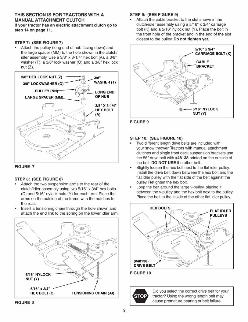
STEP 7: (SEE FIGURE 7)• Attachthepulley(longendofhubfacingdown)and
the large spacer (MM) to the hole shown in the clutch/idlerassembly.Usea3/8"x3-1/4"hexbolt(A),a3/8"washer(T),a3/8"lockwasher(O)anda3/8"hexlocknut (Z).
FIGURE 7
FIGURE 9
STEP 9: (SEE FIGURE 9)• Attachthecablebrackettotheslotshownintheclutch/idlerassemblyusinga5/16"x3/4"carriagebolt(K)anda5/16"nylocknut(Y).Placetheboltinthefrontholeofthebracketandintheendoftheslotclosest to the pulley. Do not tighten yet.
CABLEBRACKET
5/16" x 3/4"CARRIAGE BOLT (K)
5/16" NYLOCK NUT (Y)
THIS SECTION IS FOR TRACTORS WITH A MANUAL ATTACHMENT CLUTCH If your tractor has an electric attachment clutch go to step 14 on page 11.
FIGURE 10
HEX BOLTS
(#48138)DRIVE BELT
FLAT IDLERPULLEYS
STOPDidyouselectthecorrectdrivebeltforyourtractor?Usingthewronglengthbeltmaycauseprematurebearingorbeltfailure.
STEP 10: (SEE FIGURE 10)• Twodifferentlengthdrivebeltsareincludedwithyoursnowthrower.Tractorswithmanualattachmentclutchesandsinglefrontdecksuspensionbracketsusethe56"drivebeltwith#48138 printed on the outside of thebelt.DO NOT USEtheotherbelt.
• Slightlyloosenthehexboltnexttotheflatidlerpulley.Installthedrivebeltdownbetweenthehexboltandtheflatidlerpulleywiththeflatsideofthebeltagainstthepulley.Retightenthehexbolt.
• Loopthebeltaroundthelargev-pulley,placingitbetweenthev-pulleyandthehexboltnexttothepulley.Placethebelttotheinsideoftheotherflatidlerpulley.
5/16" NYLOCKNUT (Y)
5/16" x 3/4"HEX BOLT (C) TENSIONING CHAIN (JJ)
FIGURE 8
STEP 8: (SEE FIGURE 8)• Attachthetwosuspensionarmstotherearoftheclutch/idlerassemblyusingtwo5/16"x3/4"hexbolts(C)and5/16"nylocknuts(Y)foreacharm.Placethearmsontheoutsideoftheframewiththenotchestothe rear.
• Insertatensioningchainthroughtheholeshownandattachtheendlinktothespringontheloweridlerarm.

10
PIVOT LOCK PIN (GG)(use this hole)
SHOULDERBOLT (M)
L.H. HANGERBRACKET
1/8" HAIRPINCOTTER (EE)
NYLON TIE (II)
MOWERCLUTCHCABLE
FIGURE 12 VIEWED FROM LEFT SIDE
STEP 13: (SEE FIGURE 13)• Assemblethedrivebeltontotheenginepulleyfirst
and then onto the large pulley on top of the clutch/idlerassembly.Thebeltmustbeplacedinsidetheenginepulleybeltkeeper(s)andbetweenthelargepulleyandthekeeperboltnexttoit.
IMPORTANT: Do Notassemblethe"V"beltoutsideoftheenginepulleykeepersoroutsideofthekeeperboltnext to the large pulley.
• Go to step 48 on page 21.
FIGURE 13 VIEWED FROM UNDERNEATH
ENGINE PULLEY ENGINE PULLEY
Left Side of Tractor
ENGINE PULLEY KEEPER
ENGINE PULLEY KEEPER
KEEPER BOLT
IDLER PULLEY
CLUTCH/IDLER ASSEMBLY
FIGURE 11
5/64" HAIRCOTTER PIN
SPACER
1/4" WASHER
TRACTOR'SCLUTCH CABLE
CABLEBRACKET GROOVE
5/64" HAIRCOTTER PIN (DD)
1/4" WASHER (P)
SPACER (LL)
TRACTOR'SCLUTCH CABLE
CABLEBRACKET
5/64" HAIRCOTTER PIN (DD)
ATTACH CLUTCH IDLER ASSEMBLY TO TRACTOR
STEP 12: (SEE FIGURE 12)• Attachtheclutch/idlerassemblytothetractorframe.Hookthenotchedsuspensionarmsontothetwoshoulderbolts(M)assembledtotheoutsideofthetractorframe.LiftthefrontoftheassemblyandattachittotheR.H.andL.H.hangerbracketsusingtwopivotlockpins(GG)and1/8"hairpincotters(EE).
• Looselyattachthemowerclutchcabletotheleftsideofthetractorframewithanylontie(II).Do not pull thenylontiecompletelytight.Thecablemayneedtoberemovedfromthenylontiewhenusingthemowerdeck.
STEP 11: (SEE FIGURE 11)• Findthecableclipthatisattachedtotheleftsideofthetractorframeunderneaththefootrest.Opentheclipandremovethemowerclutchcable.Do not removetheclipfromthetractorframe.Thecablereattachestotheclipwhenusingthemowerdeck.
• Movetheattachmentclutchleveronthedashpaneltothe disengaged position.
• Placetheclutch/idlerassemblyonthefloorontheleftside of the tractor.
• Attachthetractor'smowerclutchcabletothecablebracketontheclutch/idlerassembly.Securethecablehousingguide(groovedown)tothecablebracketusing the original collar and a 5/64" hair cotter pin (DD).
• Placeaspacer(LL)ontheweldedpinontheidlerarm.Hooktheendoftheclutchcablespringoverthepin and secure it with a 1/4" washer (P) and a 5/64" hair cotter pin (DD).
• Aligncablebracketwithweldedpinandtightenthenutassembledinstep9.
11
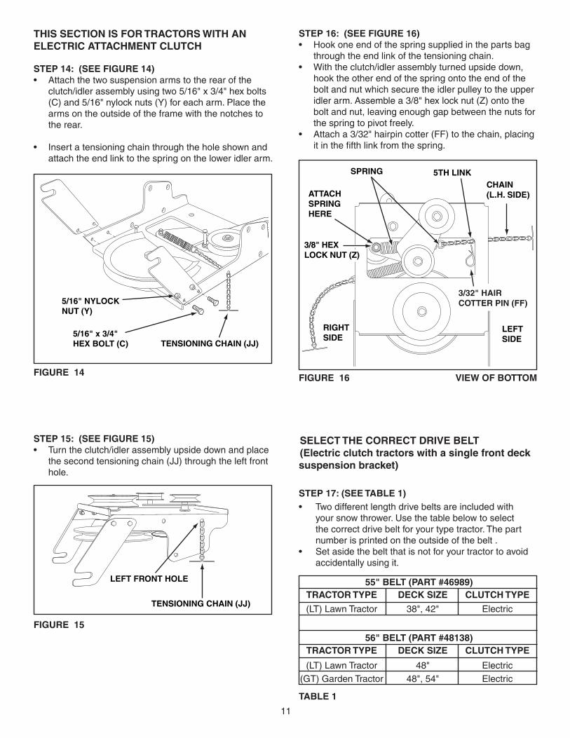
THIS SECTION IS FOR TRACTORS WITH AN ELECTRIC ATTACHMENT CLUTCH
STEP 14: (SEE FIGURE 14)• Attachthetwosuspensionarmstotherearoftheclutch/idlerassemblyusingtwo5/16"x3/4"hexbolts(C)and5/16"nylocknuts(Y)foreacharm.Placethearmsontheoutsideoftheframewiththenotchestothe rear.
• Insertatensioningchainthroughtheholeshownandattachtheendlinktothespringontheloweridlerarm.
FIGURE 14 FIGURE 16 VIEW OF BOTTOM
STEP 16: (SEE FIGURE 16)• Hookoneendofthespringsuppliedinthepartsbagthroughtheendlinkofthetensioningchain.
• Withtheclutch/idlerassemblyturnedupsidedown,hooktheotherendofthespringontotheendoftheboltandnutwhichsecuretheidlerpulleytotheupperidlerarm.Assemblea3/8"hexlocknut(Z)ontotheboltandnut,leavingenoughgapbetweenthenutsforthe spring to pivot freely.
• Attacha3/32"hairpincotter(FF)tothechain,placingitinthefifthlinkfromthespring.
CHAIN (L.H. SIDE)
3/32" HAIR COTTER PIN (FF)
5TH LINK
LEFT SIDE
3/8" HEX LOCK NUT (Z)
SPRING
RIGHT SIDE
ATTACH SPRING HERE
STEP 15: (SEE FIGURE 15)• Turntheclutch/idlerassemblyupsidedownandplace
the second tensioning chain (JJ) through the left front hole.
FIGURE 15
TENSIONING CHAIN (JJ)
LEFT FRONT HOLE
STEP 17: (SEE TABLE 1)• Twodifferentlengthdrivebeltsareincludedwithyoursnowthrower.Usethetablebelowtoselectthecorrectdrivebeltforyourtypetractor.Thepartnumberisprintedontheoutsideofthebelt.
• Setasidethebeltthatisnotforyourtractortoavoidaccidentally using it.
SELECT THE CORRECT DRIVE BELT(Electric clutch tractors with a single front deck suspension bracket)
55" BELT (PART #46989) TRACTOR TYPE DECK SIZE CLUTCH TYPE
(LT) Lawn Tractor 38", 42" Electric
56" BELT (PART #48138) TRACTOR TYPE DECK SIZE CLUTCH TYPE
(LT) Lawn Tractor 48" Electric (GT) Garden Tractor 48", 54" Electric
TABLE 1
5/16" NYLOCKNUT (Y)
5/16" x 3/4"HEX BOLT (C) TENSIONING CHAIN (JJ)

12
STEP 19: (SEE FIGURE 18)• Attachtheclutch/idlerassemblytothetractorframe.Hookthenotchedsuspensionarmsontothetwoshoulderbolts(M)assembledtotheoutsideofthetractorframe.LiftthefrontoftheassemblyandattachittotheR.H.andL.H.hangerbracketsusingtwopivotlockpins(GG)and1/8"hairpincotters(EE).
PIVOT LOCK PIN (GG)(use second hole) SHOULDER
BOLT (M)
1/8" HAIRPINCOTTER (EE)
L.H. HANGERBRACKET
FIGURE 18 VIEWED FROM LEFT SIDE
STEP 20: (SEE FIGURE 19)• Assemblethedrivebeltontotheenginepulleyfirst
and then onto the large pulley on top of the clutch/idlerassembly.Placethebelttotheinsideoftheidlerpulleyandthebeltkeeperboltlocatedbesidethelarge pulley.
• Placetensiononthebeltbypullingtheleftsidetensioning chain (JJ) out as far as the 3/32" hairpin cotter in the chain will allow. Secure the chain in this positionbyinsertinga1/8"hairpincotter(EE)throughthe chain.
IMPORTANT: Do Notassemblethedrivebeltaroundtheoutsideofthekeeperboltbesidethelargepulley.
• Go to step 48 on page 21.
FIGURE 19 VIEWED FROM UNDERNEATH
1/8" HAIRPIN COTTER (EE)
ENGINE PULLEY ENGINE PULLEY
KEEPER BOLT
IDLER PULLEY
CHAIN (JJ) (L.H. SIDE)
FIGURE 17
STEP 18: (SEE FIGURE 17)• Turntheclutch/idlerassemblyrightsideup.• Slightlyloosenthehexboltnexttotheflatidlerpulley.Installthedrivebeltdownbetweenthehexboltandtheflatidlerpulleywiththeflatsideofthebeltagainstthepulley.Retightenthehexbolt.
• Loopthebeltaroundthelargev-pulley,placingitbetweenthev-pulleyandthehexboltnexttothepulley.
STOPDidyouchoosethecorrectdrivebeltforyourtractor?Usingthewronglengthbeltmaycauseprematurebearingorbeltfailure.
CLUTCH/IDLER ASSEMBLY
HEX BOLTS
DRIVE BELT
FLAT IDLERPULLEY

13
STEP 22: (SEE FIGURE 21)• FastentheR.H.SidePlate(bendfacingout)tothefrontthreeholesshowninthetractorframeusingthree3/8"x1"threadformingbolts(E),three3/8"lockwashers(O)andone1/2"washer(R)placedonthethirdboltasashimbetweenthesideplateandtheframe.Tightenallbolts.RepeatfortheL.H.side.
NOTE:Ifyouinstalledaboltinthefourthholeinstep21,assemblea5/16"flangenut(W)ontotheboltaftertheside plate is installed.• Go to step 25 on this page.
(3) 3/8" x 1"THREAD FORMINGBOLTS (E)
5/16" FLANGEDNUT (W)(SEE NOTE)
(3) 3/8" LOCKWASHERS (O)
1/2" WASHER (R)5/16" x 1"CARRIAGE BOLT (J)(SEE NOTE)
FIGURE 21 RIGHT SIDE VIEW
FRONT SUSPENSIONBRACKET
REMOVE BOLTS IF PRESENT
FIGURE 22 RIGHT SIDE VIEW
STEP 23: (SEE FIGURE 22)• Removeanyboltsfoundintheholesshown.
STEP 21: (SEE FIGURE 20)• Removeboltsfromfrontthreeholesshown.• Ifaboltispresentinthefourthhole,replaceitwitha5/16"x1"carriagebolt(J)withoutanut.Thebracketfastenedtoinsideofframemustremaininplace.
FRONTSUSPENSIONBRACKET
REPLACE BOLT(IF PRESENT)
REMOVE BOLTS(IF PRESENT)
FIGURE 20 RIGHT SIDE VIEW
INSTRUCTIONS FOR TRACTORS WITH DUAL FRONT DECK SUSPENSION BRACKETS
FASTEN SIDE PLATES TO TRACTORIfyourtractorresemblesfigure20,startwithstep21.Ifyourtractorresemblesfigure22,startwithstep23.
STEP 25: (SEE FIGURE 24)• Assembleashoulderbolt(L)anda3/8"washer(T)totheoutsideofeachsideplate,securingthemwitha3/8"flangednut(X).
FIGURE 24 RIGHT SIDE VIEW
3/8" WASHER (T)
SHOULDER BOLT (L)
3/8" FLANGEDNUT (X)
STEP 24: (SEE FIGURE 23)• FastentheR.H.SidePlate(bendfacingout)tothethreeholesshowninthetractorframe.Usethree3/8"x1"threadformingbolts(E),3/8"lockwashers(O)and1/2"washers(R).Usethe1/2"washersasshimsbetweentheSidePlateandthetractorframe.TightenallboltsandrepeatfortheL.H.side.
NOTE:Iftheboltinsertsfreelyintothefronthole,assemblea3/8"flangednut(X)ontothebolt.
(3) 3/8" x 1"THREAD FORMINGBOLTS (E)
(3) 3/8" LOCKWASHERS (O)
3/8" FLANGED NUT (X)(SEE NOTE)
(3) 1/2" WASHERS (R)
FIGURE 23 RIGHT SIDE VIEW

14
FIGURE 28 RIGHT SIDE VIEW
INSTALLING HANGER BRACKETS Forbetterclearance,lowerthetractor'ssuspensionarmsusingtheattachmentliftlever.
STEP 26: (SEE FIGURE 25 or 26)On Tractors With Foot Rest Brackets• RemovetheboltandnutthatfastentheL.H.andR.H.footrestbracketstotheframe.
• AttachtheL.H.HangerBracket(marked"L")totheinsideofthetractorframeusingtwo3/8"x1"carriagebolts(G)and3/8"flangednuts(X).Boltheadsgooninsideoftractorframe.RepeatfortheR.H.side.
FIGURE 26 LEFT SIDE VIEW
FIGURE 25 LEFT SIDE VIEW
On Tractors Without Foot Rest Brackets• Findtheemptyholebeneaththefootrest.AttachtheL.H.HangerBracket(marked"L")totheinsideoftheframeusinga3/8"x1"carriagebolt(G)anda3/8"flangednut(X).Boltheadgoesoninsideoftractorframe.RepeatfortheR.H.side.
STEP 28: (SEE FIGURE 28)• Assembleashoulderbolt(L)and3/8"flangednut(X)totheR.H.sideofthetractorframe,usingthefirstemptyholetotherearoftheR.H.hangerbracket.Boltgoesoninsideofframe.
FIGURE 27 LEFT SIDE VIEW
INSTALLING SHOULDER BOLTS
STEP 27: (SEE FIGURE 27)• Removethebolt,washerandnutwhichfastentheswaybarbrackettotheL.H.sideofthetractorframe.Replacewithashoulderbolt(L)anda3/8"flangednut(X).Boltgoesoninsideofframe.
BOLT REMOVEDFROM THIS HOLE
SWAY BARBRACKET
SHOULDER BOLT (L)
3/8"FLANGEDNUT (X)
3/8" x 1"CARRIAGEBOLT (G)
3/8" FLANGEDNUT (X)
L.H. HANGERBRACKET
SUSPENSION ARM
SHOULDER BOLT (L)
3/8"FLANGEDNUT (X)
R.H. HANGER BRACKET
BOLT REMOVEDFROM THIS HOLE
3/8" x 1"CARRIAGEBOLT (K)
3/8" FLANGEDNUT (X)
L.H. HANGERBRACKET
SUSPENSION ARM

15
INSTALLING CLUTCH/IDLER ASSEMBLY This section covers the installation of the Clutch/Idler assemblytotractorswithattachmentclutchesthatareeitherrodoperated(p.15),cableoperated(p.17)orelectric (p. 19). Use the appropriate instructions for your tractor.
ROD OPERATED MANUAL ATTACHMENT CLUTCH
STEP 29: (SEE FIGURE 29)• Movetheattachmentclutchleveronthedashpanelto
the disengaged (down) position.• Screwthetrunnion(CC)ontotheendofthesnowthrowerengagementrod.
• Locatetheclutcharm(wherethemowerclutchrodwas connected) underneath the right hand side the tractor,justtotheinsideofthesuspensionarm.If there is an extension attached to the clutch lever, the extension,boltandnutmustberemovedandstoredwiththemowerdeck.
IMPORTANT: Re-attach the extension to the clutch leverbeforereinstallingthemowerdeck.
• Positiontheengagementrodtotheinsideoftheclutcharmandinsertthedrilledendoftherodthroughthearm.Securewitha5/64"hairpincotter(DD).
FIGURE 29 RIGHT SIDE VIEW
ENGAGEMENT ROD
5/64" HAIRPINCOTTER (DD)
TRACTOR'S CLUTCH ARM
SUSPENSION ARM
TRUNNION (CC)
REMOVE EXTENSION,BOLT AND NUT(IF PRESENT)
STEP 30: (SEE FIGURE 30)• Attachthetwosuspensionarmstotheinsideoftheclutch/idlerassemblyusingtwo5/16"x3/4"hexbolts(C),5/16"washers(Q)and5/16"nylocknuts(Y)foreacharm.Placethewashersbetweenthearmsandtheassemblyframe.
• Insertatensioningchainthroughtheholeshownandattachtheendlinktothespringontheloweridlerarm.
FIGURE 30
5/16" x 3/4"HEX BOLT (C)
5/16" NYLOCKNUT (Y)
TENSIONING CHAIN (JJ)
5/16" WASHER (Q)
FIGURE 31
STOPDidyouchoosethecorrectdrivebeltforyourtractor?Usingthewronglengthbeltmaycauseprematurebearingorbeltfailure.
HEX BOLTS
DRIVE BELT
FLAT IDLERPULLEY
(#46989)
STEP 31: (SEE FIGURE 31)• Twodifferentlengthdrivebeltsareincludedwithyoursnowthrower.Tractorswithmanualattachmentclutchesanddualfrontdecksuspensionbracketsusethe55"drivebeltwith#46989 printed on the outside ofthebelt.DO NOT USEtheotherbelt.
• Slightlyloosenthehexboltnexttotheflatidlerpulley.Installthedrivebeltdownbetweenthehexboltandtheflatidlerpulleywiththeflatsideofthebeltagainstthepulley.Retightenthehexbolt.
• Loopthebeltaroundthelargev-pulley,placingitbetweenthev-pulleyandthehexboltnexttothepulley.

16
FIGURE 33 RIGHT SIDE VIEW
FIGURE 32 RIGHT SIDE VIEW
PIVOT LOCK PIN (GG)(use second hole)
1/8" HAIRPIN COTTER (EE)ENGAGEMENT
ROD
STEP 33: (SEE FIGURE 33)• Makesuretheattachmentclutchleveronthedash
panel is in the disengaged (down) position.• Pivottheupperidlerarmsothatitrestsagainstthestopboltandispointingtowardthefrontasshown.Screw the trunnion (CC) along the threads of the engagementroduntilitisalignedatthefrontendoftheidlerarmslot.Attachthetrunnion(CC)totheslotusing the 3/8" thin washer (S) and a 5/64" hairpin cotter (DD).
• Removetheenginepulleykeeperfromthesideofthetractorframebyremovingthewasherandnutthatsecurethekeeper.Attachthenewpulleykeepersupplied with the snow thrower, reusing the original bolt,washerandnut.
NOTE:Sometractorsmayalreadybeequippedwithapulleykeeperthatisidenticaltothenewonesupplied.
IDLER ARM
5/64" HAIRPINCOTTER (DD)
TRUNNION (CC)
STOP BOLT
3/8" THINWASHER (S)
NEW ENGINE PULLEY KEEPER WITHORIGINAL BOLT, NUT AND WASHER
STEP 34: (SEE FIGURE 34)• Assembletheshort"V"beltontotheenginepulley
and then onto the large pulley on top of the clutch/idlerassembly.Thebeltmustbeplacedtotheinsideoftheenginepulleykeeper,theidlerpulleyandthekeeperboltlocatedbesidethelargepulley.
IMPORTANT: Do Notassemblethe"V"beltaroundtheoutsideoftheenginepulleykeeperorthekeeperbolt.
• Go to step 48 on page 21.
FIGURE 34 VIEWED FROM UNDERNEATH
ENGINE PULLEY
KEEPER BOLT
IDLER PULLEY
ENGINE PULLEY KEEPER
Left Side of Tractor
CLUTCH/IDLER ASSEMBLY
STEP 32: (SEE FIGURE 32)• Besuretoliftupthefrontendoftheengagementrodasshownwhenperformingthenextoperation.Youcantemporarilysupporttherodusingarubberbandtiedtotheenginepulleykeeper.
• Attachtheclutch/idlerassemblytothetractorframeasfollows.Hooktheassembly'snotchedarmsontothetwoshoulderboltsyouassembledtotheinsideofthetractorframe.LiftthefrontoftheassemblyandattachittotheR.H.andL.H.hangerbracketsusingtwopivotlockpins(GG)and1/8"hairpincotters(EE).

17
FIGURE 36
FIGURE 38
STEP 36: (SEE FIGURE 36)• Assemblethecablebrackettotheclutch/idlerassemblyusingtwo5/16"x3/4"carriagebolts(K)and5/16"nylocknuts(Y).Usethetwofrontholesinthecablebracketifyourtractorhasa42"mowerdeck.Usethetworearholesifyourtractorhasa46"mowerdeck.
STEP 38: (SEE FIGURE 38)• Movetheattachmentclutchleveronthedashpanelto
the disengaged (down) position.• Placetheclutch/idlerassemblyonthefloorontheright
side of the tractor.• Attachthetractor'sclutchcabletothecablebracket.Securethecablehousingguide(groovedown)tothecablebracketusingtheoriginalcollaranda5/64"haircotter pin (DD).
• Placeaspacer(LL)ontheweldedpinontheidlerarm.Hooktheendoftheclutchspringoverthepinandsecure it with a 1/4" washer (P) and a 5/64" hair cotter pin (DD).
CABLE BRACKET
5/16" x 3/4" CARRIAGE BOLT (K)
5/16" NYLOCKNUT (Y)
42"DECKS
46"DECKS
TRACTOR'SCLUTCH CABLE
5/64" HAIRCOTTER PIN (DD)
1/4" WASHER (P)
SPACER (LL)
5/64" HAIRCOTTER PIN (DD)
STEP 35: (SEE FIGURE 35)• Attachthetwosuspensionarmstotherearoftheclutch/idlerassemblyusingtwo5/16"x3/4"hexbolts(C),5/16"washer(Q)and5/16"nylocknuts(Y)foreacharm.Placethearmsontheoutsideoftheframewith the notches to the rear.
• Insertatensioningchainthroughtheholeshownandattachtheendlinktothespringontheloweridlerarm.
FIGURE 35
5/16" x 3/4"HEX BOLT (C)
5/16" NYLOCKNUT (Y)
TENSIONING CHAIN (JJ)
5/16" WASHER (Q)
CABLE OPERATED MANUAL ATTACHMENT CLUTCH
FIGURE 37
HEX BOLTS
DRIVE BELT
FLAT IDLERPULLEY
(#46989)
STEP 37: (SEE FIGURE 37)• Twodifferentlengthdrivebeltsareincludedwithyoursnowthrower.Tractorswithmanualattachmentclutchesanddualfrontdecksuspensionbracketsusethe55"drivebeltwith#46989 printed on the outside ofthebelt.DO NOT USEtheotherbelt.
STOPDidyouchoosethecorrectdrivebeltforyourtractor?Usingthewronglengthbeltmaycauseprematurebearingorbeltfailure.
• Slightlyloosenthehexboltnexttotheflatidlerpulley.Installthedrivebeltdownbetweenthehexboltandtheflatidlerpulleywiththeflatsideofthebeltagainstthepulley.Retightenthehexbolt.
• Loopthebeltaroundthelargev-pulley,placingitbetweenthev-pulleyandthehexboltnexttothepulley.
18
FIGURE 40 VIEWED FROM UNDERNEATH
FIGURE 39
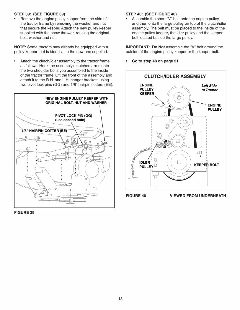
STEP 40: (SEE FIGURE 40)• Assembletheshort"V"beltontotheenginepulley
and then onto the large pulley on top of the clutch/idler assembly.Thebeltmustbeplacedtotheinsideoftheenginepulleykeeper,theidlerpulleyandthekeeperboltlocatedbesidethelargepulley.
IMPORTANT: Do Notassemblethe"V"beltaroundtheoutsideoftheenginepulleykeeperorthekeeperbolt.
• Go to step 48 on page 21.
STEP 39: (SEE FIGURE 39)• Removetheenginepulleykeeperfromthesideofthetractorframebyremovingthewasherandnutthatsecurethekeeper.Attachthenewpulleykeepersupplied with the snow thrower, reusing the original bolt,washerandnut.
NOTE:Sometractorsmayalreadybeequippedwithapulleykeeperthatisidenticaltothenewonesupplied.
• Attachtheclutch/idlerassemblytothetractorframeasfollows.Hooktheassembly'snotchedarmsontothetwoshoulderboltsyouassembledtotheinsideofthetractorframe.LiftthefrontoftheassemblyandattachittotheR.H.andL.H.hangerbracketsusingtwopivotlockpins(GG)and1/8"hairpincotters(EE).
NEW ENGINE PULLEY KEEPER WITHORIGINAL BOLT, NUT AND WASHER
PIVOT LOCK PIN (GG)(use second hole)
1/8" HAIRPIN COTTER (EE)
ENGINE PULLEY
KEEPER BOLT IDLER PULLEY
ENGINE PULLEY KEEPER
Left Side of Tractor
CLUTCH/IDLER ASSEMBLY

19
ELECTRIC ATTACHMENT CLUTCHES
FIGURE 42
TENSIONING CHAIN (JJ)
LEFT FRONT HOLE
FIGURE 43 VIEW OF BOTTOM
STEP 43: (SEE FIGURE 43)• Hookthespringfromthepartsbagthroughtheendof
the tensioning chain.• Hooktheotherendofthespringontothebottomoftheboltandnutwhichsecuretheidlerpulleytotheupperidlerarm.Holdtheboltheadandassemblea3/8"hexlocknut(Z)ontothebolt,leavingenoughspaceforthespringtopivotfreelybetweenthetwonuts.
• Attacha3/32"hairpincotter(FF)tothechain,placingitinthefifthlinkfromthespring.
CHAIN (L.H. SIDE)
3/32" HAIR COTTER PIN (FF)
5TH LINK
LEFT SIDE
3/8" HEX LOCK NUT (Z)
SPRING
RIGHT SIDE
ATTACH SPRING HERE
STEP 44: (SEE TABLE 2)• Twodifferentlengthdrivebeltsareincludedwithyoursnowthrower.Usethetablebelowtoselectthecorrectdrivebeltforyourtypetractor.Thepartnumberisprintedontheoutsideofthebelt.
• Setasidethebeltthatisnotforyourtractortoavoidaccidentally using it.
55" BELT (PART #46989) TRACTOR TYPE DECK SIZE CLUTCH TYPE
56" BELT (PART #48138) TRACTOR TYPE DECK SIZE CLUTCH TYPE
(LT) Lawn Tractor 48" Electric
(LT) Lawn Tractor 38", 42", 46" Electric
TABLE 2
STEP 41: (SEE FIGURE 41)• Attachthetwosuspensionarmstotherearoftheclutch/idlerassemblyusingtwo5/16"x3/4"hexbolts(C),5/16"washer(Q)and5/16"nylocknuts(Y)foreacharm.Placethearmsontheoutsideoftheframewith the notches to the rear.
• Insertatensioningchainthroughtheholeshownandattachtheendlinktothespringontheloweridlerarm.
FIGURE 41
STEP 42: (SEE FIGURE 42)• Pacetheextratensioningchain(JJ)throughtheleftfrontholeintheclutch/idlerassemblyandthenturntheassemblyupsidedown.
5/16" x 3/4"HEX BOLT (C)
5/16" NYLOCKNUT (Y)
TENSIONING CHAIN (JJ)
5/16" WASHER (Q)

20
FIGURE 46 VIEWED FROM UNDERNEATH
1/8" HAIRPIN COTTER (EE)
ENGINE PULLEY ENGINE PULLEY
Left Side of Tractor
KEEPER BOLT
IDLER PULLEY
STEP 47: (SEE FIGURE 46)• Assemblethedrivebeltontotheenginepulleyand
then onto the large pulley on top of the clutch/idler assembly.Thebeltmustbeplacedtotheinsideoftheidlerpulleyandthekeeperboltlocatedbesidethelarge pulley.
• Placetensiononthebeltbypullingtheleftsidetensioning chain out as far as the 3/32" hairpin cotter (FF)willallow.Securethechaininthispositionbyinserting a 1/8" hairpin cotter (EE) through the chain.
IMPORTANT: Do Notassemblethe"V"beltaroundtheoutsideoftheenginepulleykeeperorthekeeperbolt.
STEP 46: (SEE FIGURE 45)• Attachtheclutch/idlerassemblytothetractorframeasfollows.Hooktheassembly'snotchedarmsontothetwoshoulderboltsyouassembledtotheinsideofthetractorframe.LiftthefrontoftheassemblyandattachittotheR.H.andL.H.hangerbracketsusingtwopivotlockpins(GG)and1/8"hairpincotters(EE).
FIGURE 45 RIGHT SIDE VIEW
PIVOT LOCK PIN (GG)(use second hole)
1/8" HAIRPIN COTTER (EE)
CLUTCH/IDLER ASSEMBLY
HEX BOLTS
DRIVE BELT
FLAT IDLER PULLEY
FIGURE 44
STOPDidyouchoosethecorrectdrivebeltforyourtractor?Usingthewronglengthbeltmaycauseprematurebearingorbeltfailure.
STEP 45: (SEE FIGURE 44)• Turntheclutch/idlerassemblyrightsideup.• Slightlyloosenthehexboltnexttotheflatidlerpulley.Installthedrivebeltdownbetweenthehexboltandtheflatidlerpulleywiththeflatsideofthebeltagainstthepulley.Retightenthehexbolt.
• Loopthebeltaroundthelargev-pulley,placingitbetweenthev-pulleyandthehexboltnexttothepulley.Placethebelttotheinsideoftheotherflatidlerpulley.

21
STEP 48: (SEE FIGURE 47)• Placethelifthandleintotheliftbracketontherightsideofthesnowthrower.Fastenthehandletothebracketusingtwo5/16"x1-3/4"hexbolts(B)and5/16"Nylocknuts (Y).
FIGURE 48 RIGHT SIDE VIEW
NOTE:Besuretheliftreleasecable'splasticcoveringstaysinsertedintothetriggerassemblyforthenextstep.
STEP 49: (SEE FIGURE 48)• Pushthelifthandledownintothelockedposition.Inserttheendofthecablewireintotheholeintheliftrod.Placethethreadedfittingintotheslotintheliftbracket,withonehexnutaboveandonehexnutandthelockwasherbelowtheslot.Tightenthenuts,adjustingthemtoeliminateslackinthecablewire.ReferalsototheServiceandAdjustmentssectiononpage27inthismanual.
HINT: Foreasierassemblyoftheliftreleasecable,tiltthesnow thrower forward onto the spiral auger.
FIGURE 47 RIGHT SIDE VIEW
5/16" NYLOCK NUT (Y)
5/16" x 1-3/4" HEX BOLT (B)
ASSEMBLY OF THE SNOW THROWER STEP 50: (SEE FIGURE 49)• Tiltthesnowthrowerbackdowntotheground.• Removethenylontiewhichfastenstheaugerdrivebelttothedischargehousing,leavingthebeltassembledaroundthepulleys.
• Removethenylontiewhichfastensthechutecrankrodtothecrankrodsupporttube.
• Assemblethecrankrodsupporttubetothebracketon the left side of the discharge housing using two 5/16"x1-1/4"carriagebolts(I),and5/16"Nylocknuts(Y).
FIGURE 50 LEFT SIDE VIEW
STEP 51: (SEE FIGURE 50)• Attachthechutetiltcontrolassemblytothetopsideofthecranksupporttubeusingtwo5/16"x1-3/4"carriagebolts(H),bowedwashers(U)and5/16"Nylocknuts(Y).
5/16" NYLOCK NUT (Y)
5/16" x 1-1/4"CARRIAGE BOLT (I)
CRANK RODSUPPORT TUBE
DISCHARGEHOUSING
FIGURE 49 LEFT SIDE VIEW
CHUTE CRANK ROD
CRANK SUPPORT TUBE
TILT CONTROL HANDLE
5/16" x 1-3/4"CARRIAGE BOLT (H)
BOWED WASHER (U)
5/16" NYLOCK NUT (Y)
TILTCONTROL
ASSEMBLY
LIFT RELEASE CABLE
HEX NUT
LOCKWASHER
HEX NUT
CABLEWIRE
LIFTROD
TRIGGERASSEMBLY

22
5/16" NYLOCK NUT (Y)
CHUTE CRANKBRACKET
5/16" WASHER (Q)
CHUTECRANKROD
RODSUPPORTBRACKET
5/16" x 1"CARRIAGE BOLT (J)
SPIRAL
FIGURE 51 LEFT SIDE VIEW
FIGURE 52 RIGHT SIDE VIEW
CHUTE KEEPER (BB)
ANTI-ROTATIONBRACKET
1/4" FLANGEDLOCK NUT (V)
1/4" FLATWASHER (P)
1/4" x 1" HEX BOLT (D)
PLASTIC CAP (HH)
GREASEDSURFACE
FLANGE
STEP 53: (SEE FIGURE 52)• Coatthetopoftheringaroundthedischargeopening
with general purpose grease.• Placethedischargechute(facingforward)ontothering.Placetheanti-rotationbracketontopofthechuteflange,aligningitwiththeholesontherighthandsideoftheflange.Attachthethreechutekeepers(BB)(rightsideupasshown)tothebottomoftheflangeusingsix1/4"x1"hexbolts(D),1/4"flatwashers(P)and1/4"flangedlocknuts(V).Tighten carefully so thatthenutsaresnugbutdonotdigintotheplasticchutekeepers.
• Placetheplasticcap(HH)ontotheshortendoftheanti-rotationbracket.
• Positionthecrankrodspiral(seefigure51)sothatitdoesnotrubagainstthebottomsofthenotchesinthechuteflange.Tighten the nuts.
• Checkifthecrankrodrotatesthechutefreely.Ifnot,loosenby1/4turneachofthesixhexboltsholdingthechutekeeperstothechuteflange.
• Securethecontrolcablestothecrankrodsupporttubeusinganylontie(II).
STEP 54: (SEE FIGURE 53)Skip this step if you have a lawn tractor.This step is for garden tractors only.• Ifyouhavea(GT)GardenTractor,removethestopboltsfromeachsideofthesnowthrowerframe.
STEP 52: (SEE FIGURE 51)• Attachthechutecrankrodassemblybracketstotheplasticbracketontheleftsideofthedischargehousing.Alignthechutecrankbracketbeneaththerodsupportbracketandassemblebothtotheplasticbracketusingtwo5/16"x1"carriagebolts(J),5/16"washers(Q)and5/16"Nylocknuts(Y).Do not tighten yet.
STOP BOLT
FIGURE 53 RIGHT SIDE VIEW

23
STEP 55: (SEE FIGURE 54)• Placethesnowthroweronaflat,levelsurface.• RemovetheAttachmentPinfromthesnowthrower.• Extendtheaugerbeltoutbehindthesnowthrower,keepingthebeltassembledtothesnowthrowerpulleys.
• Rollthetractorupbehindthesnowthrower,centeringitbetweenthesnowthrower'smountingplates.
• Raisetherearofthesnowthrowerbyliftinguponthelifthandleuntilthenotchesinthemountingplatesalignwiththeshoulderboltsinthetractor'ssideplates.Guidetheboltsintothenotches.
• Delayinstallingtheattachmentpinuntilyouhaveassembledthebeltasinstructedinsteps56and57.
ATTACHING SNOW THROWER TO TRACTOR
STEP 56: (SEE FIGURE 55)• Theaugerbeltcomespreassembledtothepulleysonthesnowthrowerhousing.Makesurethebeltpassesover the top of the auger pulley and then twists 1/4 turn to pass underneath each side idler pulley. The "V"sideofthebeltmustmatewiththegroovesofthepulleys.
FIGURE 56 VIEWED FROM UNDERNEATH
CLUTCH/IDLER ASSEMBLY
INSTALLING THE AUGER BELTSTEP 57: (SEE FIGURE 56)• Removetheattachmentpin,ifinstalled.• Pushthelifthandledowntoincreaseslackinthebelt.• Swingtheloweridlerarmovertotheleftside.• Placetheaugerbeltaroundtherearpulleyandbetweenthetwopulleysontheidlerarm.The"V"sideofthebeltmustbeseatedinthegroovesoftheV-pulleys.
IDLER PULLEY
AUGER PULLEYTWIST 1/4 TURN
TWIST 1/4 TURN
IDLER PULLEY
FIGURE 55
ATTACHMENT PIN(After installing auger belt)
1/8" HAIRPINCOTTER (EE)
SHOULDERBOLT
MOUNTINGPLATE
SIDE PLATE
FIGURE 54 RIGHT SIDE VIEW
IDLER ARM
REAR PULLEY
LEFT SIDE OF TRACTOR
BELT ROUTING DIAGRAM
ENGINE PULLEY

24
INSTALLING THE ATTACHMENT PIN
STEP 58: (REFER BACK TO FIGURE 54 ON PAGE 23)• Liftthefrontofthesnowblowertoaligntheholesinthemountingplatesandthesideplates.Fromtheleftsideofthetractorinserttheattachmentpinthroughtheholes.Secureitwithbyreinstallingthe1/8"hairpincotter (EE).
SETTING THE AUGER BELT TENSION
STEP 59: (SEE FIGURE 57)• Pullthetensioningchainuntiltheendofthespringis
pulled through the hole in the side of the Clutch/Idler assembly.Installa1/8"hairpincotter(EE)throughthe end of the spring, securing it on the outside of the Clutch/Idlerassembly.
IMPORTANT:Forcorrectbelttension,the 1/8" hairpincotter must attach to the end of the spring, not to thechain.
NOTE;Topreventthechainfromdraggingontheground,looptheendofthechainthoughthepivotlockpin.Refertofigure45onpage20.
FIGURE 57 VIEWED FROM UNDERNEATH
END OF SPRING
1/8" HAIRPIN COTTER (EE)
LEFT SIDE OF TRACTOR
FLAT PULLEY
CLUTCH/IDLER ASSEMBLY
REAR REFLECTORS (KK)
ATTACH REFLECTORS TO REAR FENDERSTEP 59: (SEE FIGURE 58)• Ifyourtractorisnotequippedwithrearreflectors,assemblethesuppliedrearreflectors(KK)totherearfender.Placethereflectorsasclosetothebottomofthe fender and as far apart as the shape of the fender will allow.
FIGURE 58
CHECKLIST
Before you operate your snow thrower, please review the following checklist to help ensure that you will obtain the best performance from your snow thrower.
1. Allassemblyinstructionshavebeencompletedwithallboltsandnutsproperlytightened.
2. Checktheenginebeltandtheaugerbelt.Makesurethey are routed properly around pulleys and inside all beltkeepers.
3. Checkdischargechuteforproperrotation.
4. Checkoperationoftiltcontrolforupperchute.
5. Verifythatthelifthandlewilllockintoandreleasefromthe raised transport position. (Refer to the Service and Adjustmentssection.)
6. Checkskidshoeadjustment.(RefertotheServiceandAdjustmentssection.)
Operating instructions begin on page 25.

25
OPERATION
KNOW YOUR SNOW THROWERRead this owner's manual and safety rules before operating your snow thrower.Comparetheillustrationbelowwithyoursnowthrowertofamiliarizeyourselfwiththevariouscontrolsandtheirlocations.
CHUTE TILT HANDLE Pivots the Upper Chute up or down to control the angle and distance of discharge.CRANK ROD Rotates the Lower and Upper Chutes to control the direction of discharge.LIFT HANDLE Used to lift or lower the snow thrower to transport or operating position.LIFT RELEASE TRIGGERReleasesthelockwhich holds the snow thrower in the transport position
UPPER AND LOWER DISCHARGE CHUTE Controls direction and height of snow discharge.SCRAPER PLATEReplaceableplatethatabsorbswearandimpactfromcontactwithground.SKID SHOEControlsamountofclearancebetween the scraper plate and the ground.SPIRAL AUGER, R.H. & L.H. Feed snow to theimpellerfanatthecenterofthehousing.
BEFORE STARTING• Usetheendofassemblychecklisttoverifythatallinstructionshavebeenproperlycompleted.
• Makesuretheskidshoesareadjustedtomaintainadequategroundclearancebetweenthesnowthrowerandthetypeofsurfacetobecleared.(RefertotheServiceandAdjustmentssection.)
• Makesurethetractorenginehasthecorrectoilfor winter operation (SAE 5W-30). Refer to tractor owner'smanual.
HOW TO START YOUR SNOW THROWER• Thetractorshouldbesittingwiththeenginerunningatfullthrottle.Movetheattachmentclutchtotheengagedposition,startingthesnowthrowerbeforethe tractor clutch is engaged.
HOW TO STOP YOUR SNOW THROWER• Tostopthesnowthrower,disengagethetractor'sattachmentclutchleverformanualclutchesortheclutch switch for electric clutches. Refer to your tractor owner'smanual.
CAUTION: Never direct discharge towardsbystandersorwindows.Donotallow anyone in front of unit.
CONTROLLING SNOW DISCHARGE • Tocontrolthedirectionsnowisthrown,thedischargechutehas180degreesofrotation.Turnthecrankrodclockwisetorotatethechutetotheleft.Turnthecrankrodcounterclockwisetorotatethechutetotheright.
• Tocontrolthedistancesnowisthrown,theuppersection of the discharge chute pivots up and down. Push forward on the chute tilt handle to pivot the chute down, decreasing the distance snow is thrown. Pullbackonthehandletopivotthechuteup,increasing the distance snow is thrown.
HOW TO USE YOUR SNOW THROWER
LIFT HANDLELIFT RELEASE TRIGGER
CRANK ROD
CHUTE TILT HANDLE
UPPER CHUTE
LOWER CHUTE
SPIRAL AUGERS, R.H. & L.H.
SKID SHOESCRAPER PLATE

26
RAISING AND LOWERING• Toraise,pushdownonthelifthandleuntilthesnowthrowerlocksintheraisedtransportposition.
• Tolower,pushdownslightlyonthelifthandleandpullthe trigger. With the trigger pulled, slowly lower the snow thrower until it reaches the ground.
CUSTOMER RESPONSIBILITIES• Readandfollowthemaintenancescheduleandthemaintenanceprocedureslistedinthissection.
Service Dates
Checkforloosefasteners X Checkscraperandshoesforwear X X Cleaning X LubricationSection X
MAINTENANCE SCHEDULE Fill in dates as you completeregularservice. Before each
use
After e
ach use
Every
seaso
n
Before storage
LUBRICATION• Oil all pivot points on the snow thrower.• Oilthepivotpointsofthetwoidlerarmsontheclutch/idlerassembly.
• Applypenetratingoiltothecontrolcablesofthedischarge chute.
• Applyagoodgradeofspraylubricanttothetriggerassemblyandthechutetiltcontrolassembly.
CAUTION: Do not operate the snow thrower without the rear weight attached to the tractor to provide extra traction and stability.
MAINTENANCE
CHECK SCRAPER AND SHOES FOR WEAR(Refer to figures 59 and 60 on page 27)• Thescraperplateandskidshoesonthebottomofthesnowthroweraresubjecttowear.Topreventdamageto the spiral auger housing, replace plate and shoes beforewearisexcessive.
REMOVING SNOW Snowremovalconditionsvarygreatlyfromlightfluffysnowfalltowetheavysnow.Operatinginstructionsmustbeflexibletofittheconditionsencountered.Theoperatormustadaptthelawntractorandsnowthrowertodepthofsnow,winddirection,temperatureandsurfaceconditions.• Beforebeginningoperation,thoroughlyinspecttheareaofoperationandremovealldoormats,sleds,boards,wiresandotherforeignobjects.
• Thespiralaugerspeedisdirectlyrelatedtoenginespeed.Formaximumsnowremovalanddischarge,maintainhighenginer.p.m.(fullthrottle).Itisadvisableto operate the lawn tractor at a slow ground speed (1stgear)forsafeandefficientsnowremoval.
• Indeep,driftedorbankedsnowitwillbenecessarytouse full throttle and a slow ground speed (1st gear). Driveforwardintothesnow,depressthetractor'sclutch-brakepedalandallowthespiralaugertoclearthesnow.Repeatthismethoduntilapathiscleared.Onthesecondpass,overlapthefirstenoughtoallowthe snow thrower to handle the snow without repeated stoppingandstartingofforwardmotion.
• Inextremelydeepsnow,raisethesnowthrowerfromthegroundtoremovethetoplayeranddriveforwardonly until the tractors front tires reach the uncleared bottomlayerofsnow.Depressthetractor'sclutch-brakepedalandallowthespiralaugertoclearthesnow. Reverse the tractor and lower the snow thrower to the ground. Drive the tractor forward until the snow againbecomestoodeep.Repeatingthisprocessintoand out of drifts will eventually clear even the deepest of snow piles.
• Ifthesnowthrowerbecomescloggedwithsnoworjammedwithaforeignobject,disengagethesnowthrowerimmediatelyandshutoffthetractorengine.Unclogthesnowthrowerbeforeresumingoperation.
OPERATING TIPS• Dischargesnowdownwindwheneverpossible.• Tohelppreventsnowfromstickingtothesnowthrower,allowthesnowthrowertoreachoutdoortemperaturebeforeusingit.Alightcoatofwaxmayalsobeappliedto the inside surface of the snow thrower housing and discharge chute.
• Usetirechainstoimprovetraction.• Userearwheelweightstoimprovetraction.• Beforethefirstsnowfall,removeallstones,sticksandotherobjectswhichcouldbecomehiddenbythesnow.Permanentobstaclesshouldbemarkedforvisibility.
• Overlap eachpass slightly to assure complete snowremoval.
DANGER: Shut off engine and disengagesnowthrowerbeforeunclogging discharge chute. Unclog using awoodenstick,notyourhands.

27
SERVICE AND ADJUSTMENTS
CAUTION: Beforeservicingoradjustingthesnowthrower,shutofftheengine,removethesparkplugwire(s),settheparkingbrakeandremovethekeyfromthetractorignition.
FIGURE 60
FIGURE 59
REPLACING AUGER BELT• Disengagethetractor'sattachmentclutch.• Lowerthesnowthrowertotheground.• Removetheattachmentpin.• Lockthesnowthrower'slifthandleinthedownpositiontodecreasebelttension.
• Releasethespringtensionfromtheaugerbeltidlerarmonthebottomoftheclutch/idlerassembly.
• Removetheaugerdrivebeltfromtheclutch/idlerassemblyandfromthespiralaugerhousing.
• Installnewbeltovertopoflargeaugerdrivepulleyandunderthetwosideidlerpulleys.Twistthebelt1/4turntoseatthe"V"ofthebeltinthegrooveofeachidler pulley. Refer to figure55onpage23.
• Assemblethebeltontotheclutch/idlerassembly.
SKID SHOE ADJUSTMENT• Theskidshoesaremountedoneachsideofthespiral
auger housing. They regulate the distance the scraper plateisraisedabovetheplowingsurface.Whenremovingsnowfromagraveldrivewayorandunevensurface,itisadvisabletokeepthescraperplateashighabovethesurfaceaspossibletopreventpossibledamagetothespiralauger.Onblacktoporconcretesurface,keepthescraperplateasclosetothesurfaceaspossible.
• Raisethesnowthroweroffthegroundandplaceablockundereachendofthescraperplate.Loosenthesixhexnutssecuringtheskidshoestothehousing.Adjusttheskidshoesupordownandretightenthenutssecurely.Adjustbothskidshoestothesameheighttokeepthehousingandthescraperplatelevel.Seefigure59.
LIFT RELEASE CABLE ADJUSTMENT• Iftheliftroddoesnotlockthesnowthrowersecurely
in the transport position, loosen the upper hex nut on theliftbracketafewturnsandtightenthelowerhexnut.Refertofigure48onpage21.
• Iftheliftrodfailstounlockcompletelytolowerthesnow thrower, loosen the lower hex nut on the lift bracketafewturnsandtightentheupperhexnut.Refertofigure48onpage21.
CLUTCH DISENGAGEMENT ADJUSTMENT(For tractors with engagement rod clutches only.Not for electric clutches or cable clutches) If the spiral auger on the snow thrower does not stop whentheattachmentclutchleveronthetractorisdisengaged,thenadjustmentisnecessary.Proceedasfollows.Referbacktofigure33onpage16.• Placetheattachmentclutchleverinthedisengaged
position.• Removethehairpincotterfromtheengagementrod
trunnion and lift the trunnion out of the hole in the idler arm.
• Screwthetrunnionafewturnstowardsthefrontendof the rod.
• Replacethetrunnionintotheholeintheidlerarmandsecure it with the hairpin cotter.
Checktheoperationofthesnowthrower.Ifthespiralaugersstilldonotstop,repeattheabovestepsuntiltheaugersstopwhentheattachmentclutchleverisplaced in the disengaged position.
SPIRAL AUGERS• Thespiralaugersaresecuredtotheaugershaftwithtwoshearboltsandnylocknuts.Ifyouhitaforeignobjectorificejamstheaugers,thesnowthrowerisdesignedsothattheboltswillshear.
• Iftheaugerswillnotturn,checktoseeiftheshearboltshavesheared.Seefigure60.Tworeplacementshearboltsandnylocknutshavebeenprovidedwiththesnowthrower.Forfutureuseorderpartnumber710-0890Ashearboltandnumber47810nylocknut.

28
PARTS TO REMOVE AT END OF SEASON
• Removetheclutch/idlerassembly.(Thetwohangerbracketsandthetwoshoulderboltsmaybeleftattachedtothetractorframe.)
• Removethedrivebeltfromtheenginepulley.• Ifyoureplacedtheenginepulleykeeperonamanualattachmentclutchtractor,reinstallthetractor'soriginalenginepulleykeeper.Seefigure33onpage16orfigure39onpage18.
• Ifyouhavearodoperatedattachmentclutch,removetheengagementrodfromthetractor'sclutcharm.Seefigure29onpage15.
• Ifarearmountedattachmentistobeused,removetherearweighttray,leavingtheboltsthatyouinstalledinthesidesofthetractordrawbar.Retightenthebolts.
• Ifafrontmountedattachmentistobeused,removethesideplatesfromthetractor.Besuretoassembleboltsbackintotheemptyholesinthetractorframe.
STORAGE RECOMMENDATIONS• Lowerthesnowthrowertotheground.• Removethesnowthrowerfromthetractor.• Cleanthesnowthrowerthoroughly.Washoffanysaltdepositwhichmayhavedriedonthethrowerandhousing.
• Anybaremetalthathasbecomeexposedshouldbepainted or coated with a light oil to prevent rust.
• Storeinadryplace.
REMOVING THE SPIRAL AUGER HOUSING• Lowerthesnowthrowertotheground.• Removetheattachmentpin.Seefigure54onpage
23.• Lockthesnowthrower'slifthandleinthedownpositiontodecreasebelttension.
• Releasethespringtensionfromtheaugerbeltidlerarmonthebottomoftheclutch/idlerassembly.
• Removetheaugerdrivebeltfromtheclutch/idlerassembly.Seefigure56onpage23.
• Pullthespiralaugerhousingassemblyoffofthetractor.
CAUSEPROBLEM CORRECTION
Clogged discharge chute
Spiralaugersdon'tturn
Snow thrower stalls tractor engine
TROUBLESHOOTING
STORAGE
1.UpperorlowerVbelttooloose 1.IncreasetensiononVbelt2.UpperorlowerVbeltbroken 2.ReplaceVbelt3.Shearboltsaresheared. 3.Replaceshearbolts
1. Tractor ground speed too fast 1. Use lower tractor gear2. Tractor throttle set too low 2. Increase to full throttle3. Snow too deep 3. Raise the snow thrower4.Snowmeltsduringcontactwith 4.Allowsnowthrowertocooltothesnowthrower outdoortemperaturebeforeusing
Front wheels slide instead of steering
Snow thrower rides up over snow
1.Objectjammedinspiralauger 1.Stopengine,disengagethesnow thrower clutch and clear the auger
2. Hard or heavy snow 2. Increase to full throttle and decrease ground speed
Not enough traction at front wheels 1. Increase scraper plate clearance byloweringskidshoes
2. Pull down on lift handle to increase weight on front wheels
1. Tractor ground speed too fast 1. Reduce ground speed2.Bottomsnowisicyorhardpacked 2.Lowertheskidshoessothatfront ofskidshoeislowerthantherear

29
NOTES

30
PARTS
REPAIR PARTS FOR MODEL LST42D 42" SNOW THROWER

31
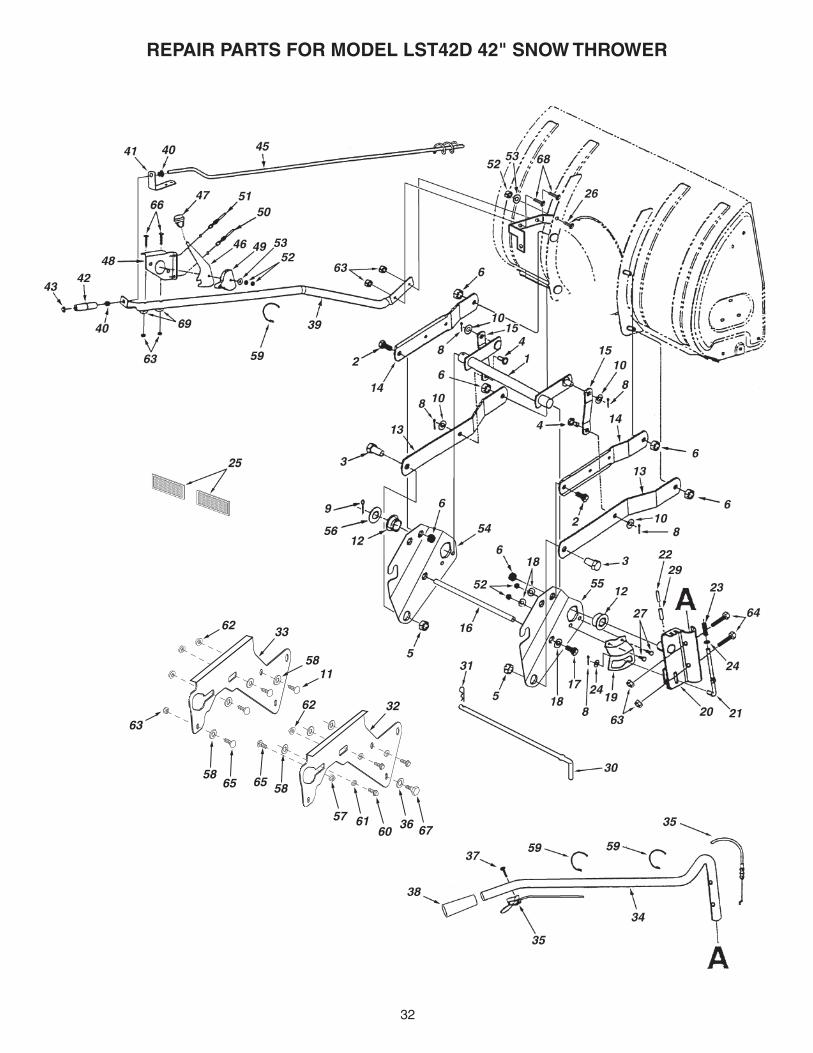
REPAIR PARTS FOR MODEL LST42D 42" SNOW THROWER
REF. PART QTY. DESCRIPTION NO. NO.
1 05931 1 Housing, Bearing 2 65701 1 HousingAssembly 3 71464 1 GearAssembly 4 63579 1 ChuteCrankRodAssembly 5 63768 1 ImpellerAssembly 6 24773 1 Scraper Plate 7 25982 1 Shaft,AugerGearbox 8 703-2735A 1 Bracket,ChuteCrank 9 24816 1 Cover, Belt 10 705-5226 1 ChuteReinforcement 11 705-5269 1 SpiralAssembly,L.H.(notshown) 12 705-5270 1 SpiralAssembly,R.H. 13 43840 2 Hex Bolt, 5/16-18 x 1-1/4" Lg. 14 44950 4 Carriage Bolt, 1/4-20 x 3/4" 15 44917 1 Palnut, 3/8" 16 44326 4 Carriage Bolt, 5/16-18 x 1" Lg. 17 43080 10 Carriage Bolt, 5/16-18 x 3/4" Lg. 18 46703 8 Bolt, Self-Tap 5/16" x 3/4" 19 710-0890A 2 Bolt, Shear 5/16-18 x 1-1/2" 20 43088 11 Washer, 1/4" 21 43070 2 Washer, 3/8" 22 47189 4 HexNut,1/4-20Nylock 23 47810 29 HexNut,5/16-18Nylock 24 715-0114 2 Spiral Pin, 1/4" x 1-1/2" Lg. 25 750-0437 1 Bushing 26 731-1379A 1 Chute Adapter 27 43086 4 LockWasher,5/16" 28 43009 6 Washer, .76" x 1.49" x .06" 29 711-0469 4 Spacer, .75 ID x 1.25 OD x .5 L 30 43081 24 Washer, 5/16" Std. Wrt. 31 47615 2 Bearing, Flange 32 741-0309 1 Bearing, Ball 33 741-0475 2 Bushing, Plastic 3/8" 34 741-0493A 4 Bearing, Split, 3/4" 35 24279 2 SkidShoe 36 48015 4 Washer, Nylon 37 784-5618 2 Housing, Bearing 38 24393 1 Bracket,ChuteCrank
REF. PART QTY. DESCRIPTION NO. NO.
39 27280 1 Bracket,Idler 40 49933 2 Shoulder Bolt, Round Head 41 65367 1 HangerBracketAssembly,L.H. 42 65450 1 HangerBracketAssembly,R.H. 43 41576 2 Hex Bolt, 3/8-16 x 1-3/4" 44 44377 1 Hex Bolt, 3/8-24 x 1" 45 784-5594 1 Bracket,Cable 46 746-0929 1 Cable,ChuteControlWithClip 47 711-0242 2 Spacer 48 746-0928 1 Cable,ChuteControl 49 HA21362 4 HexNut,3/8-16Nylock 50 43038 2 Pin,PivotLock 51 43343 2 Pin, Hair Cotter #4 (1/8") 52 43350 4 Carriage Bolt, 3/8-16 x 1" 53 24394 1 Bracket,ChuteAnti-rotation 54 47572 6 HexLockNut,3/8-16Flanged 55 1643-60 1 Plastic Cap 56 64452 1 HangerBracketAssembly,R.H. 57 64451 1 HangerBracketAssembly,L.H. 58 47043 1 Keeper, Engine Pulley 59 48106 4 Bolt, Shoulder 60 24466 2 Bracket,DownStop 61 736-0247 1 Washer, 62 47598 6 HexLockNut,1/4"Flanged 63 731-0921 1 Chute, Upper 64 731-1313C 1 Guide,Cable 65 47044 2 Pulley, V Type 4" 66 47026 1 Pulley, V Type 67 43085 1 Hex Bolt, 5/16-18 x 1-1/2" 68 710-0896 1 Screw, 1/4-14 x 5/8" 69 731-0851A 3 Chute Keeper 70 43661 6 Hex Bolt, 1/4-20 x 1" 71 731-1300C 1 Chute, Lower 72 25937 1 CenterBrace,Gearbox 73 HA20185 1 #61 Woodruff Key 74 43182 3 Hex Bolt, 5/16-18 x 3/4" 75 40504 1 Carriage Bolt, 1/4-20 x 3/4"
42320 1 Owner'sManual
32
REPAIR PARTS FOR MODEL LST42D 42" SNOW THROWER
673660
57 61
65 58
62
11
6558
58
62
63
32
33

33
REF. PART QTY. DESCRIPTION NO. NO.
1 64637 1 LiftShaftAssembly 2 710-0865 2 Hex Bolt, 1/2-13 x 1" 3 710-0367 2 Hex Bolt, 5/8-11 x 1-1/2" 4 711-0332 2 Pin,BracketLift 5 712-0261 2 Nut,HexLock5/8-11Thread 6 43262 6 Nut,HexLock1/2-13 8 142 5 Pin, Cotter 1/8" x 3/4" 9 43093 1 Pin, Cotter 1/8" x 1-1/2" 10 R19171616 4 Washer, 17/32" x 1" 11 43350 6 Carriage Bolt, 3/8-16 x 1" 12 741-0192 2 Bearing, Flange With Flats 13 783-0380 2 Link,15.80"Long 14 783-0381 2 Link,11.75"Long 15 24476 2 Link,4.88"Long 16 24311 1 Rod, Spacer 17 47599 2 HexBolt,5/16-18x1"(Locking) 18 43086 4 LockWasher,5/16" 19 24820 1 Bracket,Lift 20 63773 1 Assembly,HandleLiftBracket 21 48049 1 Rod, Index Lift 22 47369 1 Pin, Spring 3/16" x 1-3/4" 23 732-0306 1 Spring,Compression 24 R19131316 2 Washer, 13/32" x 13/16" 25 47788 2 Reflector,Rear 26 43080 1 Carriage Bolt, 5/16-18 x 3/4" 27 43182 2 Hex Bolt, 5/16-18 x 3/4" 29 47368 1 Pin, Spring 5/16" x 1-3/4" 30 46954 1 Pin,Attachment 31 43343 1 Pin, Haircotter #4 (1/8") 32 25678 1 Plate, Side (R.H.) 33 25679 1 Plate, Side (L.H.) 34 49916 1 Tube,LiftHandle 35 49912 1 TriggerandLiftCableAssembly
REF. PART QTY. DESCRIPTION NO. NO.
36 43070 2 Washer, 3/8" 37 710-1233 1 Screw, Oval #10-24 x 1" 38 44482 1 Grip, Handle 39 47027 1 Tube,CrankRodSupport 40 741-0475 2 Bushing, 3/8" Plastic 41 703-2735A 1 Bracket,ChuteCrank 42 720-0201A 1 Knob,Crank 43 44917 1 Palnut, 3/8" 45 63579 1 Assembly,ChuteCrankRod 46 784-5604A 1 Handle, Chute Tilt 47 720-04039 1 Knob 48 603-0302 1 Assembly,ChuteTiltBracket 49 731-1313C 1 Guide,Cable 50 746-0928 1 Cable,ChuteControl 51 746-0929 1 Cable,ChuteControlwithClip 52 43064 5 Nut,HexLock5/16-18 53 43081 2 Washer, 5/16" 54 24285 1 Plate, Mounting (L.H.) 55 24284 1 Plate, Mounting (R.H.) 56 43601 1 Washer, 1.59" x 1.032" x .060" 57 46584 1 Nut,Whizlock,5/16-18 58 R19172410 8 Washer, 1/2" 59 726-0178 3 Tie, Nylon 60 47631 6 Hex Bolt, 3/8-16 x 1" Self Tap 61 43003 6 LockWasher,3/8" 62 47572 6Nut,FlangedLock3/8-16 63 47810 8 Nut,NylockHex5/16-18 64 43084 2 Hex Bolt, 5/16-18 x 1-3/4" 65 44326 2 Carriage Bolt, 5/16-18 x 1" 66 44215 2 Carriage Bolt, 5/16-18 x 1-3/4" 67 48106 2 Bolt, Shoulder 68 43682 2 Carriage Bolt, 5/16-18 x 1-1/4" 69 44695 2 Washer, Bowed
REPAIR PARTS FOR MODEL LST42D 42" SNOW THROWER

34
REPAIR PARTS FOR MODEL LST42D 42" SNOW THROWER
REF. PART QTY. DESCRIPTION NO. NO.
1 43080 2 Carriage Bolt, 5/16-18 x 3/4" 2 43182 4 Hex Bolt, 5/16-18 x 3/4" 3 43083 2 Hex Nut, 5/16-18 4 43086 1 LockWasher,5/16" 5 43081 4 Washer, 5/16" Std. Wrt. 6 25727 1 Frame,ClutchandPulley 7 63904 1 IdlerArmAssembly 8 24286 1 Spacer, Pivot 9 63762 1 IdlerBracketAssembly 10 43015 1 Hex Nut, 3/8-16 11 46981 1 Pulley, V Type 9" 12 43082 8 Nut,HexLock,3/8-16 13 46982 1 Pulley, V Type 5-1/2" 14 738-0680 1 Shaft 15 750-0456 1 Spacer 16 750-0660 1 Spacer 17 43003 6 LockWasher,3/8" 18 714-0161 2 Key 19 741-0919 2 Bearing, Ball 20 08253B 1 Housing, Bearing 21 15296A 1 Housing, Open Bearing 22 14088B 1 Spacer, Spindle 23 44377 2 Hex Bolt, 3/8-24 x 1" 24 736-0247 2 Washer 25 43063 3 Hex Bolt, 5/16-18 x 1" 26 46989 1 Belt, V Type Drive (55") 48138 1 Belt, V Type Drive (56") 27 47846 1 Belt, V Type Auger 28 47044 1 Pulley, V Type 4" 29 47025 1 Hex Bolt, 5/16-18 x 3-1/2" 30 43432 1 Hex Bolt, 3/8-16 x 2-1/2" 31 43054 3 Hex Bolt, 3/8-16 x 2" 32 24571 1 Spacer 33 24472 1 Spacer, Pivot 34 43070 8 Washer, 3/8" 35 46959 1 Spring 36 46963 2 Chain 37 43055 1 Pin, Hair Cotter, 3/32" 38 23727 1 Spacer 39 43088 1 Washer, 1/4" 40 43343 2 Pin, Hair Cotter #4 (1/8") 41 47134 2 Pin, Hair Cotter 5/64" 42 711-0198 1 Trunnion 43 46948 1 Rod,Engagement 44 47620 1 Spring 45 47607 1 Spring, Torsion 46 23625 1 Spacer 47 43509 1 Hex Bolt, 3/8-16 x 2-3/4" Lg. 48 47605 1 Washer, Flat 3/8" 49 24558 1 CableBracket 50 49870 1 Hex Bolt, 1/4-20 x 2-1/2" 51 43178 2 Hex Nut, 1/4-20 52 43177 1 LockWasher,1/4" 53 48883 3 Pulley, Flat 3-5/8" 54 25728 2 RearPulleyFrameBracket 55 46938 1 Hex Bolt, 3/8-16 x 3-1/4" 56 25780 1 Spacer 57 47810 9 HexNut,5/16-18Nylock

35
SLOPE GUIDE(Keep this sheet in a safe place for future reference.)
Use this guide to determine if a slope is safe for the operation of your tractor and snow thrower. Refer also to the instructions in your vehicle owners manual.
CA
UT
ION
:
DO
N
OT
O
PE
RA
TE
YO
UR
TR
AC
TO
R
AN
D
SN
OW
T
HR
OW
ER
ON
A S
LO
PE
IN E
XC
ES
S O
F 10 D
EG
RE
ES
. BE
SU
RE
O
F Y
OU
R T
RA
CT
OR
'S T
OW
ING
AN
D B
RA
KIN
G C
AP
AB
ILIT
IES
B
EF
OR
E O
PE
RA
TIN
G O
N A
SL
OP
E. A
VO
ID A
NY
SU
DD
EN
TU
RN
S O
R
MA
NE
UV
ER
S W
HIL
E O
N A
SL
OP
E.
A P
OW
ER
PO
LE
A C
OR
NE
R O
F A
BU
ILD
ING
OR
A F
EN
CE
PO
ST
FOLD
ALO
NG
DO
TTED
LINE
, RE
PR
ES
EN
TING
A 10 D
EG
RE
E S
LOP
E
SIG
HT
AN
D H
OL
D T
HIS
LE
VE
L W
ITH
A V
ER
TIC
AL
TR
EE

the fastest way to purchase parts www.speedepart.com
REPAIR PARTSAgri-Fab,Inc.
809SouthHamiltonSullivan, IL. 61951
217-728-8388www.agri-fab.com
©2003Agri-Fab,Inc.
Thisdocument(ormanual)isprotectedundertheU.S.CopyrightLawsandthecopyrightlawsofforeigncountries,pursuanttotheUniversalCopyrightConventionandtheBerneconvention.Nopartofthisdocumentmaybereproducedortransmittedinanyformorbyanymeans,electronicormechanical,includingphotocopyingorrecording,orbyanyinformationstorageorretrievalsystem,withouttheexpresswrittenpermissionofAgri-Fab,Inc.Unauthorizedusesand/orreproductionsofthismanualwillsubjectsuchunauthorizedusertocivilandcriminalpenaltiesasprovidedbytheUnitedStates Copyright Laws.