Owner’s Manual - SpeeCo LOG SPLITTER ASSEMBLY & OPERATING INSTRUCTIONS Owner’s Manual Model...
92
KINETIC LOG SPLITTER ASSEMBLY & OPERATING INSTRUCTIONS Owner’s Manual Model Number 580899 WARNING: All operators must read this manual before operating this log splitter. Follow the safety instructions in the manual and in decals attached to the product. Failure to do so could result in serious injury or death. K1601
Transcript of Owner’s Manual - SpeeCo LOG SPLITTER ASSEMBLY & OPERATING INSTRUCTIONS Owner’s Manual Model...

KINETIC LOG SPLITTER
ASSEMBLY & OPERATING INSTRUCTIONS
Owner’s ManualModel Number
580899
WARNING: All operators must read this manual before operating this log splitter. Follow the safety instructions in the manual and in decals attached to the product. Failure to do so could result in serious injury or death.
K1601


Table of Contents
Page(s)
Important Safety Information 1-4
Intended Use 1
Personal Protective Equipment 1
Safety Decals 2
General Safety 3
Work Area 3
Preparation of the Log 3
Operation of the Log Splitter 3
General Maintanence 4
Workplace Safety 4
Towing Safety 4
Assembly Instructions 5-13
Replacement parts 14-19
Operating Instructions 20-21
Towing 22
Warranty information 23
Specifications BackCover


This is the SAFETY ALERT SYMBOL. It is used to alert you to potential personal injury hazards. Obey all safety messages that follow this symbol to avoid possible injury or death.
BEFORE operating this log splitter, make sure that you wear safety gear such as goggles or safety glasses, steel toed shoesandtightfittinggloves(withoutloosecuffsordrawstrings).Alwayswearaprotectivehearingdevicewhenoperat-ingthislogsplitter.
NEVERusethislogsplitterforanyotherpurposethansplittingwood.Itisdesignedforthisuseonly. Any other use can causeseriousinjuryordeath.
PERSONAL PROTECTIVE EQUIPMENT
INTENDED USE
NEVER wear loose clothing or jewelry that can be caught by moving parts of the log splitter. Keep clothing and hair away from all moving parts when operating this log splitter.
Page 1
WARNING: Read and thoroughly understand all instructions in this manual and on safety decals before assembling or operating this log splitter. Failure to do so may cause serious injury or death. Do not allow anyone to operate this log splitter who has not read this manual. As with all power equipment, a log splitter can be dangerous if assembled or used improperly. Do not operate this log splitter if you have any questions concerning safe operation. To get answers to any questions, call our technical support department at 1-800-525-8322.

PART NUMBER: 580386LOCATION: TOP OF BEAM, UNDER SHIELD
SAFETY DECALS
Makesurethatallsafetywarningdecalsareingoodconditionandreadable.Alwaysreplacemissingordefaceddecals.ContactSpeeCoat1-800-525-8322forreplacementdecals.
PART NUMBER: 580388LOCATION: TOP OF SHIELD
PART NUMBER: 580387LOCATION: TOP OF TONGUE
PART NUMBER: 581696LOCATION: TOP OF SHIELD
PART NUMBER: S52062500LOCATION: SIDE OF TOUNGE
PART NUMBER: S52069100LOCATION: FRONT OF SWING STAND (1), SIDES OF BEAM (2)
Page 2
PART NUMBER: 584052LOCATION: SIDE OF BEAM, TOWARD REAR

GENERAL SAFETY
• ALWAYSkeeptheoperator’smanualnearbyforreference.Rereadthemanualperiodically.• ALWAYS establish a safety zone restricting bystanders to a 10 foot radius around the log splitter when log splitter is inoperation.• ALWAYSensurethatalloperatorsareproperlytrainedandhavereadandunderstandtheoperator’smanual.• ALWAYSoperatethelogsplitterwithaclearmind,freeoftheinfluenceofalcohol,drugsormedication.• ALWAYSwearclosefittedclothing,freefromlanyards,stringsorjewelrywhichcouldbeanentrapmenthazard.• ALWAYSkeepclothingandhairawayfrommovingparts.• ALWAYSkeepsafetyshieldsinplaceduringoperation.• NEVERmanuallymovethesplitteruphillordownhill.
PREPARATION OF THE LOGBoth ends of the log should be cut as square as possible to help prevent the log from riding out of the splitter duringoperation.Donotsplitlogsgreaterthan24inchesinlength.
WORK AREA• ALWAYSoperatethislogsplitteronfirmlevelground.• ALWAYSwearproperfootwearwithadequatetraction.• ALWAYSoperateyourlogsplitterinanopenarea.(Exhaustfumescontaincarbonmonoxidewhichcanbedeadly wheninhaled.)• ALWAYSoperateyourlogsplitteronlevelground.(Operatingonaslopecouldcausethelogsplittertorolloverorlogs tofalloff.)• ALWAYSproperlychockthewheelstopreventmovementofthelogsplitterwhileinoperation.• ALWAYSoperateyourlogsplitterindaylightorundergoodartificiallight.• ALWAYSkeeptheworkareaclean.Removesplitwoodaroundyourlogsplitterimmediatelysothatyoudon’t stumble overit.
OPERATION OF THE LOG SPLITTERThe log splitter is designed for a single operator, who stands in the “operator zones”, using the hand closest to the log to operate the safety latch, and the other handtopressthecontrolhandle.Failuretooperatethelog splitter in this position can result in serious injury or death.
• ALWAYSloadthelogontothebeamupagainstthewedge.• ALWAYSbecarefulwhenmovingorliftingthelogsplitter.Gethelpifunitistooheavytomovebyyourself.• ALWAYSproperlychockthewheelstopreventmovementofthelogsplitterwhileinoperation.• NEVERplacehands,bodypartsorclothingundertheshieldsduringoperation.Movingpartscouldcause entanglement.• KNOWhowtostopthelogsplitteranddisengagethecontrolsbeforeoperatingit.• NEVER place hands or feet between the log and splitting wedge during forward or reverse stroke as this could result in seriousinjuryordeath.• NEVERstraddleorstepoverthelogsplitterduringoperation.• NEVERreachorbendoverthelogsplittertopickupalog.• NEVERtrytosplittwologsontopofeachother.• NEVERtrytocrosssplitalog.• NEVERattempttoloadyourlogsplitterwhentheramorwedgeisinmotion.• NEVERuseyourfoot,aropeoranyextensiondevicetooperatethecontrols.Onlyusebothhands.• NEVERmovethelogsplitterwhiletheengineisrunning.• ALWAYS shutofftheengineevenifyouareleavingthelogsplitterforashortperiodoftime.• NEVERtouchthemufflerandotherhotareasoftheengineduringoperation.Waituntiltheenginecoolsdown.• ALWAYS make sure the engine is turned off while routinely cleaning debris from splitter, work area and engine• ALWAYS makesurethelegissecuredinthedownposition.• ALWAYS makesurethetongueisfullyretractedpriortosplitting.• NEVERusethislogsplitterforanyotherpurposethansplittingwood.
Page 3
Failuretofollowtheseinstructionsmayresultininjuryordeath.
K1602
OPERATOR ZONE

• NEVERoperateyourlogsplitterwhenitisinpoormechanicalconditionorinneedofrepair.• NEVERmodifyyourlogsplitterinanymanner.Suchalterationsmaycauseyourlogsplittertobeunsafeandwillvoid thewarranty.• NEVERtamperwiththeenginetorunitatexcessivespeeds.Themaximumenginespeedispresetbythemanufacturer andiswithinsafetylimits.Seeengineowner’smanual.Alteringthespeedsettingwillvoidthemanufacturer’swarranty.• ALWAYSperformallrecommendedmaintenanceproceduresbeforeusingyourlogsplitter.• ALWAYSreplacealldamagedorwornpartsimmediately.• ALWAYSremovethesparkplugwirebeforeperforminganyserviceorrepaironyourlogsplitter.• ALWAYSchecktheleveloftheengineoilbeforeoperation.• ALLreplacementpartsmustmeetmanufacturer’sspecifications• PERIODICALLYplacealightamountofgreaseacrossthetopoftherack.• PERIODICALLY cleanallsplintersandwooddebrisfromrackteethandreapplygrease.• SEASONALLYgreasethepinionbearings.• PERIODICALLYcheckthatallnuts,bolts,andscrewsaretightbeforeoperation.• ALWAYScheckthedrivebeltsbeforeuseforcondition,wearandproperbelttension.• PERIODICALLYcleanandlightlyoilthetopofthebeam.• ALWAYS soak the bronze clutch bushing in light weight oil at the start of every season and after every 100 hours ofuse.• SEVERALtimesthroughoutthesplittingseasoncheckthattherackliftbearingiscleanandfreetoturn.Ifnot,clean thebearingandsupportboltandinsertgreaseintothesupportboltuntilbearingfreelyturns.
• ALWAYScheckalllocalandstateregulationsregardingtowing,licensing,andlightsbeforetowingyourlogsplitter.• ALWAYS check before towing to make sure that the log splitter is correctly and securely attached to the towing ve-
hicleandthatthesafetychainsaresecuredtothehitchorbumperofthevehiclewithenoughslacktoallowturning.AlwaysuseaClassI,2”ballwiththislogsplitter.
• ALWAYSconfirmcouplertightnesseachtimebeforetowingandaftertowing50miles.• ALWAYSdisconnectyourlogsplitterfromthetowingvehiclebeforeoperatingit.• ALWAYSbecarefulwhenbackingupwithyourlogsplitterintow.Itcouldjackknife.• ALWAYS allow for added length of your log splitter when turning, parking, and crossing intersections and in all driving
situations.• ALWAYSturnthefuelshutoffvalveontheenginetothe“OFF”positionbeforetowingthelogsplitter.Failuretodoso
mayresultinfloodingtheengine.• ALWAYSusesafetychainswhentowingyourlogsplitter.• ALWAYSreplaceballorcouplerifdamagedorexcessivelyworn.• NEVERexceed45mphwhentowingyourlogsplitter.Towingthelogsplitteratspeedshigherthan45mphcould
resultinlossofcontrol,damagetotheequipment,seriousinjuryordeath.Adjusttowingspeedforterrainandcondi-tions.
• ALWAYS beextracautiouswhentowingoverroughterrainespeciallyrailroadcrossings.• NEVERcarryanycargoorwoodonyourlogsplitter.• NEVERallowanyonetositorrideonyourlogsplitter.• NEVERexceedweightcapacityofballorloadlimitsofcoupler.• ALWAYSfullyextendandproperlylocktonguefortowing.• ALWAYSchecktireforconditionandproperinflation.Donottowunitwithworn,damagedorimproperlyinflatedtires.• ALWAYS makesurethelegissecuredintheuppositionpriortotowing. GENERAL MAINTENANCE
WORKPLACE SAFETY
IMPORTANT NOTE – (spark arrester):Asaprecautionarymeasureagainstpossibleflyingsparks,alwaystakeaClassBfireextinguisherwithyouwhenoperat-ingthislogsplitterindryareas.Thislogsplitterisequippedwithaninternalcombustionengineandshouldnotbeusedonornearanyunimprovedforest-covered,brush-coveredorgrass-coveredlandunlesstheengine’sexhaustsystemisequippedwithasparkarrestermeetingapplicablelocalorstatelaws(ifany).Ifasparkarresterisused,itshouldbemain-tainedineffectiveworkingorderbytheoperator.InthestateofCalifornia,asparkarresterisrequiredbylaw.Otherstateshavesimilarlaws.Federallawsapplyonfederallands.Asparkarrestermufflerisoptionalandavailableasanaccessoryatyournearestenginedealer.Alwayscheckthelegalrequirementsinyourarea.
TOWING SAFETY
• NEVERoperateyourlogsplitternearaflameorspark.• NEVERfillthegastankwhiletheengineishotorrunning.• ALWAYS turn off engine and allowtheenginetocoolbeforerefueling.• NEVERsmokewhileoperatingorrefuelingyourlogsplitter.Gasfumescaneasilyexplode.• NEVERstoregasolineinthehouseornearaheatingappliance.• ONLYrefuelyourlogsplitterinaclearareawithnogasfumesorspilledgas.• ALWAYSreplacethegascapsecurely.Ifgasolinehasspilled,movethelogsplitterawayfromtheareaofthespill
andavoidcreatinganysourceofignitionuntilthespilledgashasbeenproperlycleaned.• ALWAYStakeaClassBfireextinguisherwithyouwhenoperatingthislogsplitterindryareasasaprecautionary
measureagainstpossiblecombustion.• ALWAYSemptythefueltankpriortostoragetoavoidthepotentialfirehazard.• ALWAYSstoregasolineproperlyinanapprovedcontainer.• NEVERallowwoodchipsordebristobuildupontheengine.
Page 4
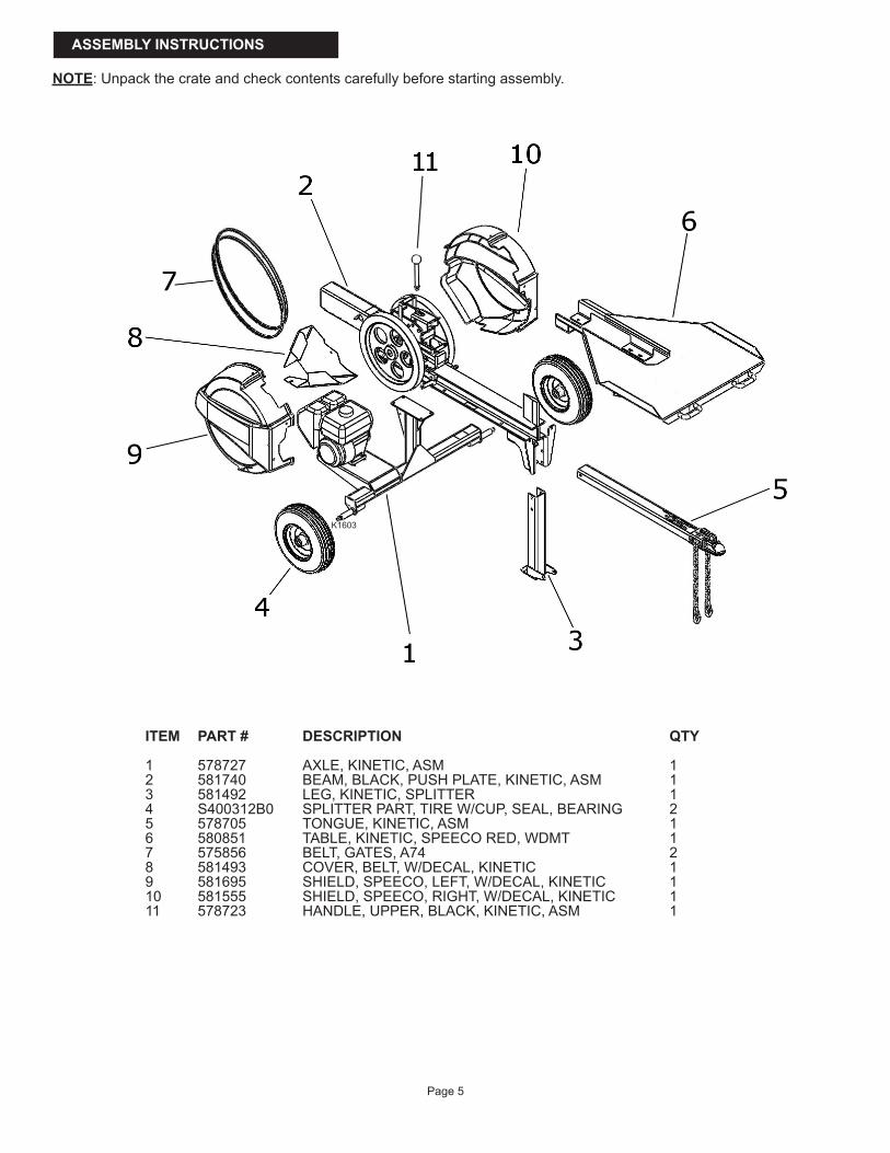
ITEM PART # DESCRIPTION QTY
1 578727 AXLE, KINETIC, ASM 12 581740 BEAM, BLACK, PUSH PLATE, KINETIC, ASM 13 581492 LEG, KINETIC, SPLITTER 14 S400312B0 SPLITTER PART, TIRE W/CUP, SEAL, BEARING 25 578705 TONGUE, KINETIC, ASM 16 580851 TABLE, KINETIC, SPEECO RED, WDMT 17 575856 BELT, GATES, A74 28 581493 COVER, BELT, W/DECAL, KINETIC 19 581695 SHIELD, SPEECO, LEFT, W/DECAL, KINETIC 110 581555 SHIELD, SPEECO, RIGHT, W/DECAL, KINETIC 111 578723 HANDLE, UPPER, BLACK, KINETIC, ASM 1
ASSEMBLY INSTRUCTIONS
NOTE:Unpackthecrateandcheckcontentscarefullybeforestartingassembly.
Page 5
K1603

BAG 580953 Part # Description QTY12 584306 BOLT, HEX, 3/8-16X1-1/2, GRADE 8 413 575805 NUT, HEX, 3/8-16UNC X 21/64, GR8 414 838 WASHER, LOCK, 3/8ID, ZINC-PLT STL 4
Bagged Hardware
BAG 580951 Part # Description QTY1 S071011C0 1/2’ X 4 1/4” SWIVEL HITCH PIN 12 576044 PIN, GROOVED, 1/2DIA, 3-3/4LG 13 584305 BOLT, HEX, 1/2-13 X 3-3/4, GR5 14 573552 NUT, NYLOCK, 1/2-13UNC X 19/32, GR5 15 576755 CLIP, E-STYLE, 1/2, YELLOW-ZINC STL 1
1
2
3
4
5
6
7
8
9
10
11
12
13
14
15
16
17
18
19
20
21
22
23
24
BAG 580952 Part # Description QTY6 575828 SCREW, PHILIPS, 1/4-20 X 1-1/4 87 2457 1/4NCx3/4HHCSGR5 48 5336 1/4 STD FLAT WASHER 89 1985 WASHER, LOCK, 1/4ID, ZINC-PLT STL 1010 583332 NUT, CNTOCK, 1/4-20UNC X 7/32, GR2 211 570789 NUT, HEX, 1/4-20UNC X 7/32, GR5 2
BAG 580954 Part # Description QTY15 20973 BOLT, CARRIAGE, 3/8-16 X 1-1/4, GR5 (Silver) 416 584306 BOLT, HEX, 3/8-16X1-1/2, GRADE 8 (Yellow) 217 570793 NUT, HEX, 3/8-16UNC X 21/64, GR5 (Silver) 418 575805 NUT, HEX, 3/8-16UNC X 21/64, GR8 (Yellow) 219 21757 WASHER, FLAT, 3/8, ZINC-PLT STL 420 838 WASHER, LOCK, 3/8ID, ZINC-PLT STL 6
BAG 580955 Part # Description QTY21 S40033200 CAP, HI SPEED TIRE AND WHEEL 222 5849 3/4 NF SLOTTED HEX NUT 223 2864 3/4 TYPE A NAR PLAIN WSHR 224 5241 1/8 X 1-1/4 COTTER PIN 2
Page 6
K1604
K1605
K1606
K1607
K1608

ASSEMBLY
Page 7
Note: The crate itself is used in the assembly process for alignment. DO NOT DISMANTLE OR DISCARD. Make sure the sides of the crate have not been damaged.
STEP 1:Setthecrateonlevelgroundwithplentyofclearspacearoundthecrateforassembly.Removethetopofthecrateandsetaside.Removealltheitemsfromthecrate.Locatehardwarebag580955and580953inthehardwarebox.STEP 2:Removewheelsfromtheirshippingbox.Removeblueplasticprotectivecapsandpositionthevalvestemsoutward.Mountthewheels(1)ontheaxleswiththevalvestemspositionedoutward.Secureusingthewashers(2)andslottednuts(3).Tightenslottednutfirmlyontheaxlespindle.Thewheelshouldbestifftoturnbyhand,thenbacktheslottednutoff1/3to1/2turn.Alignslottednutwithholeinaxlespindleandinsertthenbendcotterpin.Installthedustcap.
ITEM PART # DESCRIPTION QTY1 S400312B0 TIRE 22 BAG 580955 3/4 FLAT WASHER 23 BAG 580955 3/4 IN-16 SL-NF HEX NUT 24 BAG 580955 1/8 X 1-1/4 COTTER PIN 25 BAG 580955 DUST CAP 2
STEP 3:Placetheaxleassemblybackintothecratewiththewheelsnestedinbetweenthetwocenter-mostwoodslats.Placetheshortenginesupportsectionofwoodundertheenginemounttoholdtheaxleassemblyinitsproperposition.Makesurethatthesidesofthecratehavenotbeendamaged.
SUPPORT BLOCK
K1649
K1652

Page 8
STEP 4A:Liftthebeam(5)andplaceitintopositionaligningtheboltholesoftheaxleassembly(1)withthemountingboltholesofthebeamassembly.Partofthebeamwilloverhangthecrateandwillbesupportedbythesideofthecrate.Installthebolts(2),lockwashers(3)andnuts(4).Tightenallfourboltssecurely.
STEP 4B:Installtheswingleg(1)intheloweredposition.Installthepin(3)withthesnapring(4)throughthetophole.Installthehitchpin(2)throughthebottomholesinthebeamandswingjackleg.InstalltheR-cliptosecurepin.
ITEM PART # DESCRIPTION QTY1 578727 AXLE ASSEMBLY 12 BAG 580953 3/8-16X1-1/2, GRADE 8 HEX BOLT 43 BAG 580953 3/8ID, ZINC-PLT STL LOCK WASHER 44 BAG 580953 3/8-16UNC X 21/64, GR8 HEX NUT 45 581740 BEAM ASSEMBLY 1
ITEM PART # DESCRIPTION QTY1 581492 LEG 12 BAG 580951 1/2’ X 4 1/4” SWIVEL HITCH PIN 13 BAG 580951 1/2DIA, 3-3/4LG GROOVED PIN 14 BAG 580951 CLIP, E-STYLE, 1/2, YEL-ZINC STL 1
STEP 4C:Raisetheaxle-beamassemblyhighenoughthatthecratecanberemovedanddiscarded.Lowerthesplittertothegroundforthefinalassembly.
K1650
K1651
K1653
K1654

STEP 5A:Locatetheenginemountboltsandtensionnuts.
Page 9
TENSION NUT ENGINE MOUNT BOLT
STEP 5B:Loosen the engine mount bolts and the tension nuts very slightly to allow sliding adjustment of the engine posi-tionbutdoesnotallowtheenginetobetilted.Ensurethattheenginestayssquareandalignedwiththeflywheelwhilesettingthebelttension.
STEP 5C:LoopthetwoV-belts(5)overtheflywheel.Installthebeltsintothevchannelsontheclutchpulley,closesttothemotorfirst.
STEP 5D:Inordertosetthebelttension,usetheprovidedgaugewhichwillsetthebeltsat60poundsoftension.Pullonthebeltusingthehooksideofthegauge,asshownbelow,aboutanequaldistanceawayfromtheflywheelandclutchpulleyalongthelengthofthebelt.
HANDLE SIDE
HOOK SIDE
CLUTCHPULLEY
FLYWHEEL
K1613
K1614 K1615
K1616
K1617

Page 10
STEP 5E:Slowly pull on the belt with the gauge in one steady motion until the hook side notches align with the top surface oftheotherbeltasshown.Afteraligningthehookside,checkthetopareaofthegauge.Whenthehandlesidenotchesalignwiththeshownedge,thenthebeltbeingpulledisatthepropertension.
If the handle notches are above the edge, then the belt is too tight and the tension mustbedecreased.Movetheenginetowardsthetirestodecreasetension.
If the handle notches are below the edge, then the belt is too loose and the tension mustbeincreased.Movetheengineawayfromthetirestoincreasetension.
STEP 5F:Repeat this measurement on the other belt, tighten the engine mounting bolts, and re-check both belts to ensure thattheyarestillatpropertension.OVERTIGHTENINGOFTHEBELTWILLCAUSEPREMATUREWEARANDFAILUREOFTHECLUTCHASSEMBLY,ANDMAYCAUSEWEARONTHEENGINESHAFT.
K1618 K1620
K1619
K1622
K1621K1623
K1624

ITEM PART # DESCRIPTION QTY1 581493 BELT COVER 12 BAG 580952 1/4-20UNC X 3/4, GR5 HEX BOLT 23 BAG 580952 1/4ID, ZINC-PLT STL LOCK WASHER 24 BAG 580952 1/4-20UNC X 7/32, GR5 HEX NUT 25 575856 BELT 2
STEP 5G:Installthebeltguard(1)fromtheback,overthebeltsandfingertightenbolts(2)withwashers(3)andnuts(4)intoplace.Oncebothboltshavebeeninstalledtightenalltheboltssecurely.
Page 11
BELT COVERMOUNT LOCATIONS
K1625
STEP 6:Movethetable(4)intoplacebyslidingtableinfromthefrontofthebeamassembly.Installthebolts(1&2),flatwasher(7),lockwasher(6)andnut(3&5)ontoeachboltasinstalledandfingertightenallbolts.Securelytightenallbolts.
ITEM PART # DESCRIPTION QTY1 BAG 580954 3/8-16 X 1-1/4, GR5 CARRIAGE BOLT 42 BAG 580954 3/8-16X1-1/2, GRADE 8 HEX BOLT 23 BAG 580954 3/8-16UNC X 21/64, GR8 HEX NUT 24 580851 TABLE 15 BAG 580954 3/8-16UNC X 21/64, GR5 HEX NUT 46 BAG 580954 3/8ID, ZINC-PLT STL LOCK WASHER 67 BAG 580954 3/8, ZINC-PLT STL FLAT WASHER 4
K1655
Page 12
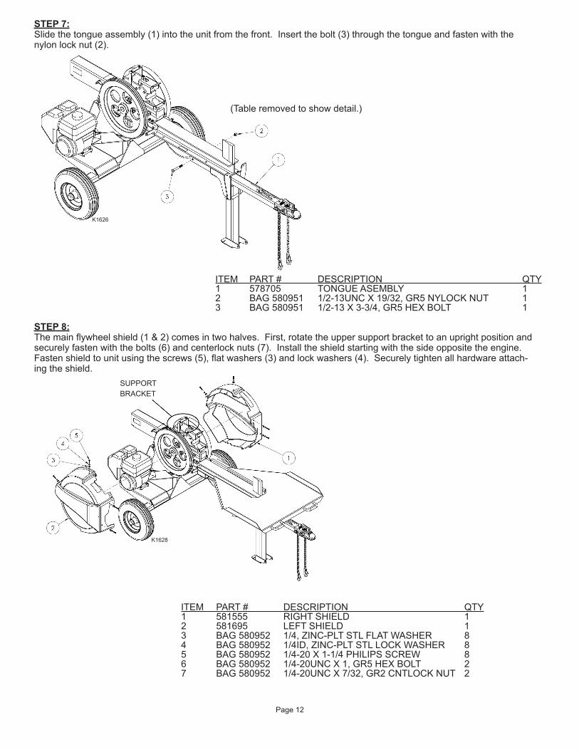
STEP 8:Themainflywheelshield(1&2)comesintwohalves.First,rotatetheuppersupportbrackettoanuprightpositionandsecurelyfastenwiththebolts(6)andcenterlocknuts(7).Installtheshieldstartingwiththesideoppositetheengine.Fastenshieldtounitusingthescrews(5),flatwashers(3)andlockwashers(4).Securelytightenallhardwareattach-ingtheshield.
ITEM PART # DESCRIPTION QTY1 581555 RIGHT SHIELD 12 581695 LEFT SHIELD 13 BAG 580952 1/4, ZINC-PLT STL FLAT WASHER 84 BAG 580952 1/4ID, ZINC-PLT STL LOCK WASHER 85 BAG 580952 1/4-20 X 1-1/4 PHILIPS SCREW 86 BAG 580952 1/4-20UNC X 1, GR5 HEX BOLT 27 BAG 580952 1/4-20UNC X 7/32, GR2 CNTLOCK NUT 2
SUPPORTBRACKET
K1628
STEP 7:Slidethetongueassembly(1)intotheunitfromthefront.Insertthebolt(3)throughthetongueandfastenwiththenylonlocknut(2).
ITEM PART # DESCRIPTION QTY1 578705 TONGUE ASEMBLY 12 BAG 580951 1/2-13UNC X 19/32, GR5 NYLOCK NUT 13 BAG 580951 1/2-13 X 3-3/4, GR5 HEX BOLT 1
K1626
(Tableremovedtoshowdetail.)
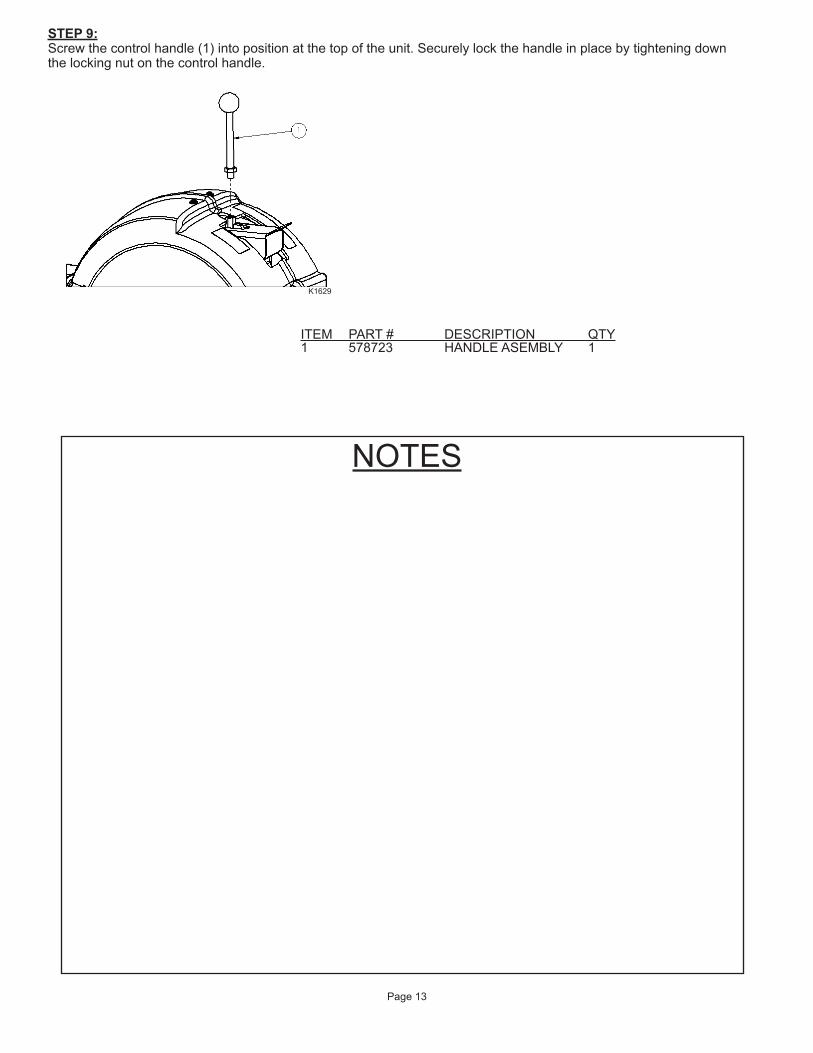
STEP 9:Screwthecontrolhandle(1)intopositionatthetopoftheunit.Securelylockthehandleinplacebytighteningdownthelockingnutonthecontrolhandle.
NOTES
Page 13
ITEM PART # DESCRIPTION QTY1 578723 HANDLE ASEMBLY 1
K1629
REPLACEMENT PARTS
Page 14
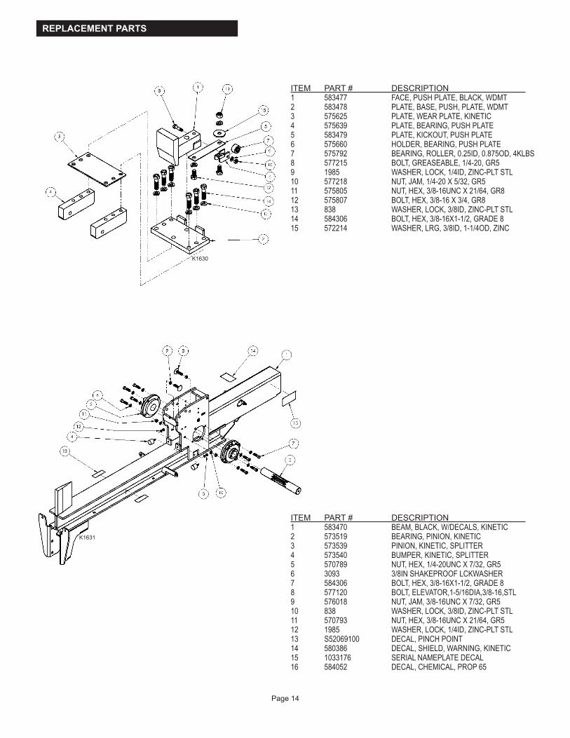
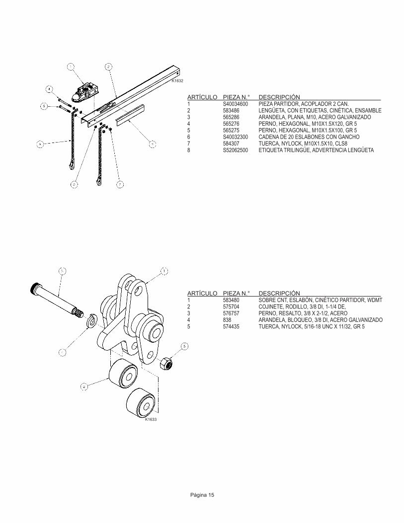
ITEM PART # DESCRIPTION 1 583477 FACE, PUSH PLATE, BLACK, WDMT2 583478 PLATE, BASE, PUSH, PLATE, WDMT3 575625 PLATE, WEAR PLATE, KINETIC4 575639 PLATE, BEARING, PUSH PLATE5 583479 PLATE, KICKOUT, PUSH PLATE6 575660 HOLDER, BEARING, PUSH PLATE7 575792 BEARING, ROLLER, 0.25ID, 0.875OD, 4KLBS8 577215 BOLT, GREASEABLE, 1/4-20, GR59 1985 WASHER, LOCK, 1/4ID, ZINC-PLT STL10 577218 NUT, JAM, 1/4-20 X 5/32, GR511 575805 NUT, HEX, 3/8-16UNC X 21/64, GR812 575807 BOLT, HEX, 3/8-16 X 3/4, GR813 838 WASHER, LOCK, 3/8ID, ZINC-PLT STL14 584306 BOLT, HEX, 3/8-16X1-1/2, GRADE 815 572214 WASHER, LRG, 3/8ID, 1-1/4OD, ZINC
ITEM PART # DESCRIPTION 1 583470 BEAM, BLACK, W/DECALS, KINETIC2 573519 BEARING, PINION, KINETIC3 573539 PINION, KINETIC, SPLITTER4 573540 BUMPER, KINETIC, SPLITTER5 570789 NUT, HEX, 1/4-20UNC X 7/32, GR56 3093 3/8IN SHAKEPROOF LCKWASHER7 584306 BOLT, HEX, 3/8-16X1-1/2, GRADE 88 577120 BOLT, ELEVATOR,1-5/16DIA,3/8-16,STL9 576018 NUT, JAM, 3/8-16UNC X 7/32, GR510 838 WASHER, LOCK, 3/8ID, ZINC-PLT STL11 570793 NUT, HEX, 3/8-16UNC X 21/64, GR512 1985 WASHER, LOCK, 1/4ID, ZINC-PLT STL13 S52069100 DECAL, PINCH POINT14 580386 DECAL, SHIELD, WARNING, KINETIC15 1033176 SERIAL NAMEPLATE DECAL 16 584052 DECAL, CHEMICAL, PROP 65
K1630
K1631

Page 15
ITEM PART # DESCRIPTION 1 S40034600 SPLITTER PART, 2 CH COUPLER2 583486 TONGUE, W/DECALS, KINETIC, ASM3 565286 WASHER, FLAT, M10, ZINC-PLT STL4 565276 BOLT, HEX, M10X1.5X120, GR55 565275 BOLT, HEX, M10X1.5X100, GR56 S40032300 20 LINK CHAIN W/ HOOK7 584307 NUT, NYLOCK, M10X1.5X10, CLS88 S52062500 TRILINGUAL DECAL, TONGUE WARNING
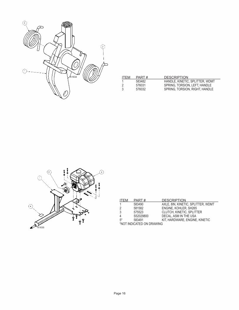
ITEM PART # DESCRIPTION 1 583480 OVER-CNT, LINKAGE, KINETIC, SPLTR, WDMT2 575704 BEARING, ROLLER, 3/8ID, 1-1/4OD3 576757 BOLT, SHOULDER, 3/8 X 2-1/2, STL4 838 WASHER, LOCK, 3/8ID, ZINC-PLT STL5 574435 NUT, NYLOCK, 5/16-18UNC X 11/32, GR5
K1632
K1633
Page 16
ITEM PART # DESCRIPTION 1 583482 HANDLE, KINETIC, SPLITTER, WDMT2 576031 SPRING, TORSION, LEFT, HANDLE3 576032 SPRING, TORSION, RIGHT, HANDLE
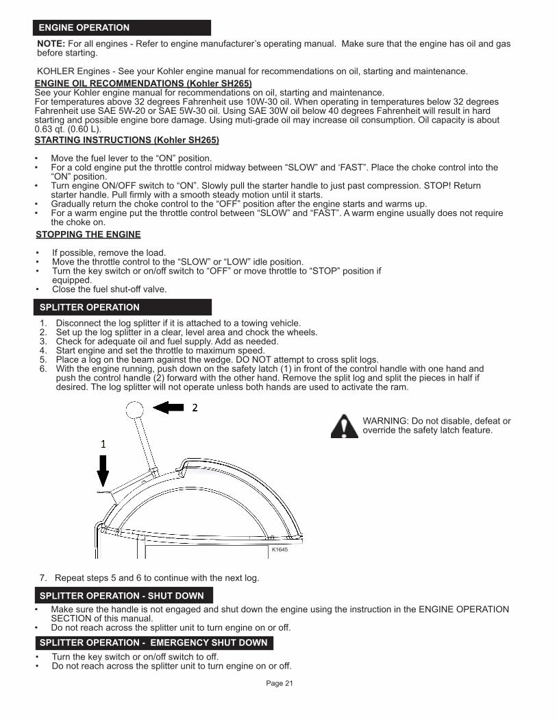
ITEM PART # DESCRIPTION 1 583490 AXLE, 8IN, KINETIC, SPLITTER, WDMT2 581582 ENGINE, KOHLER, SH2653 575523 CLUTCH, KINETIC, SPLITTER4 S52029800 DECAL, ASM IN THE USA5* 583491 KIT, HARDWARE, ENGINE, KINETIC*NOT INDICATED ON DRAWING
K1634
K1635

Page 17
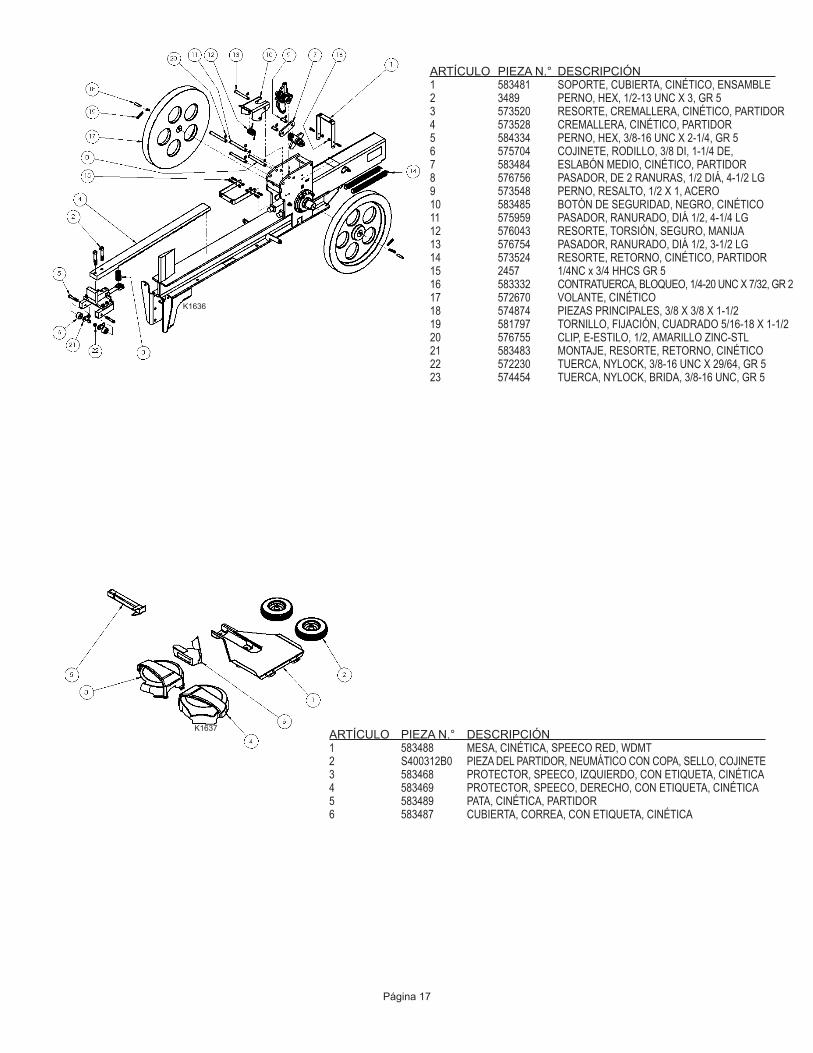
ITEM PART # DESCRIPTION 1 583481 BRACKET, COVER, KINETIC, ASM2 3489 BOLT, HEX, 1/2-13UNC X 3, GR53 573520 SPRING, RACK, KINETIC, SPLITTER4 573528 RACK, KINETIC, SPLITTER5 584334 BOLT, HEX, 3/8-16UNC X 2-1/4, GR56 575704 BEARING, ROLLER, 3/8ID, 1-1/4OD7 583484 MID-LINK, KINETIC, SPLITTER8 576756 PIN, 2-GROOVED, 1/2DIA, 4-1/2LG9 573548 BOLT, SHOULDER, 1/2 X 1, STL10 583485 SAFETY BUTTON, BLACK, KINETIC11 575959 PIN, GROOVED, 1/2DIA, 4-1/4LG12 576043 SPRING, TORSION, LOCK, HANDLE13 576754 PIN, GROOVED, 1/2DIA, 3-1/2LG14 573524 SPRING, RETURN, KINETIC, SPLITTER15 2457 1/4 NC X 3/4 HHCS, GR516 583332 NUT, CNTLOCK, 1/4-20UNC X 7/32, GR217 572670 FLYWHEEL, KINETIC18 574874 KEY STOCK, 3/8 X 3/8 X 1-1/219 581797 SCREW, SET, SQ, 5/16-18 X 1-1/220 576755 CLIP, E-STYLE, 1/2, YELLOW-ZINC STL21 583483 MOUNT, SPRING, RETURN, KINETIC22 572230 NUT, NYLOCK, 3/8-16UNC X 29/64, GR523 574454 NUT, NYLOCK, FLANGE, 3/8-16UNC,GR5
ITEM PART # DESCRIPTION 1 583488 TABLE, KINETIC, SPEECO RED, WDMT2 S400312B0 SPLITTER PART, TIRE W/CUP, SEAL, BEARING3 583468 SHIELD, SPEECO, LEFT, W/DECAL, KINETIC4 583469 SHIELD, SPEECO, RIGHT, W/DECAL, KINETIC5 583489 LEG, KINETIC, SPLITTER6 583487 COVER, BELT, W/DECAL, KINETIC
K1636
K1637

Page 18
ITEM PART # DESCRIPTION 1 575856 BELT, GATES, A742 583466 HANDLE, UPPER, BLACK, KINETIC, ASM3 583467 KIT, HARDWARE, COVER, KINETIC4 583492 KIT, HARDWARE, AXLE, KINETIC5 583539 KIT, HARDWARE, TABLE, KINETIC6 581299 MANUAL, SPEECO, SPLITTER, KINETIC7 584561 GAUGE, TENSION, KINETIC8* 580382 HANGTAG, SPEECO KINETIC9* 580457 DECAL, FEATURES, KINETIC* NOT SHOWN
ITEM PART # DESCRIPTION 1 S071011C0 1/2’ X 4 1/4” SWIVEL HITCH PIN2 576044 PIN, GROOVED, 1/2DIA, 3-3/4LG3 576755 CLIP, E-STYLE, 1/2, YELLOW-ZINC STL4 584305 BOLT, HEX, 1/2-13 X 3-3/4, GR55 573552 NUT, NYLOCK, 1/2-13UNC X 19/32, GR5
ITEM PART # DESCRIPTION 1 S40033200 CAP, HI SPEED TIRE AND WHEEL2 5849 3/4 NF SLOTTED HEX NUT3 2864 3/4 TYPE A NAR PLAIN WSHR4 5241 1/8 X 1-1/4 COTTER PIN
K1638
K1639
K1640

Page 19
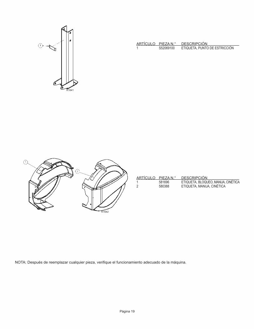
ITEM PART # DESCRIPTION 1 S52069100 DECAL, PINCH POINT
ITEM PART # DESCRIPTION 1 581696 DECAL, LOCK, HANDLE, KINETIC2 580388 DECAL, HANDLE, KINETIC
NOTE:Afteranypartsreplacemantverifytheproperoperationofthemachine.
K1641
K1642

WARNING: DO NOT PLACE YOUR HANDS UNDER THE SHIELD WHILE ENGINE IS RUNNING. WAIT A MINIMUM OF THIRTY (30) SECONDS FOR THE FLYWHEEL TO STOP AFTER THE ENGINE IS TURNED OFF TO START ANY ADJUSTMENTS.
OPERATING INSTRUCTIONS
WARNING: AT NO TIME, WHILE THE ENGINE IS RUNNING, PLACE YOUR HAND IN BETWEEN THE LOG, THE WEDGE AND THE RAM. ALWAYS KEEP YOUR HANDS CLEAR OF MOVING PARTS
WARNING: NEVER ATTEMPT TO CROSS SPLIT A LOG
NOTE:Setthelogsplitterinaclearlevelareaandchockthewheels.NOTE: Checkallfluidlevelsandadjustwithproperreplacementfluidsifnecessarybeforestartingtheengine.NOTE: Start the engine according to the engine manufacturer’s operating instruction for engine type and allow engine to cometofulloperatingspeedbeforeusingtheunit.NOTE: When splitter is not in use, turn fuel valve off per engine manufacturer’s manualNOTE: Soakthebronzeclutchbushinginlightweightoilatthestartofeveryseasonandafterevery100hoursofuse.
Page 20
WARNING: Read and thoroughly understand all instructions in this manual and on safety decals before assembling or operating this log splitter. Failure to do so may cause serious injury or death. Do not allow anyone to operate this log splitter who has not read this manual. As with all power equipment, a log splitter can be dangerous if assembled or used improperly. Do not operate this log splitter if you have any questions concerning safe operation. To get answers to any questions, call our technical support department at 1-800-525-8322.
K1643
K1644
NOTE: For all engines - Refer to enginemanufacturer’soperatingmanual.Make sure that the engine has oil and gas beforestarting.
ENGINE OIL RECOMMENDATIONS (Kohler SH265)SeeyourKohlerenginemanualforrecommendationsonoil,startingandmaintenance.Fortemperaturesabove32degreesFahrenheituse10W-30oil.Whenoperatingintemperaturesbelow32degreesFahrenheituseSAE5W-20orSAE5W-30oil.UsingSAE30Woilbelow40degreesFahrenheitwillresultinhardstartingandpossibleengineboredamage.Usingmuti-gradeoilmayincreaseoilconsumption.Oilcapacityisabout0.63qt.(0.60L).STARTING INSTRUCTIONS (Kohler SH265)
• Movethefuellevertothe“ON”position.• Foracoldengineputthethrottlecontrolmidwaybetween“SLOW”and‘FAST”.Placethechokecontrolintothe
“ON”position.• TurnengineON/OFFswitchto“ON”.Slowlypullthestarterhandletojustpastcompression.STOP!Return
starterhandle.Pullfirmlywithasmoothsteadymotionuntilitstarts.• Graduallyreturnthechokecontroltothe“OFF”positionaftertheenginestartsandwarmsup.• Forawarmengineputthethrottlecontrolbetween“SLOW”and“FAST”.Awarmengineusuallydoesnotrequire
thechokeon.STOPPING THE ENGINE
• Ifpossible,removetheload.• Movethethrottlecontroltothe“SLOW”or“LOW”idleposition.• Turn the key switch or on/off switch to “OFF” or move throttle to “STOP” position if
equipped.• Closethefuelshut-offvalve.
ENGINE OPERATION
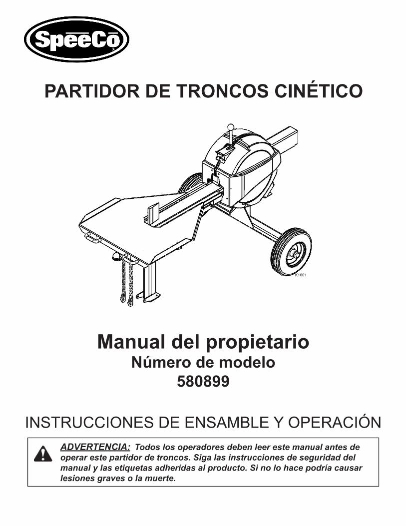
SPLITTER OPERATION1. Disconnectthelogsplitterifitisattachedtoatowingvehicle.2. Setupthelogsplitterinaclear,levelareaandchockthewheels.3. Checkforadequateoilandfuelsupply.Addasneeded.4. Startengineandsetthethrottletomaximumspeed.5. Placealogonthebeamagainstthewedge.DONOTattempttocrosssplitlogs.6. With the engine running, push down on the safety latch (1) in front of the control handle with one hand and
pushthecontrolhandle(2)forwardwiththeotherhand.Removethesplitlogandsplitthepiecesinhalfifdesired.Thelogsplitterwillnotoperateunlessbothhandsareusedtoactivatetheram.
7.Repeatsteps5and6tocontinuewiththenextlog.
SPLITTER OPERATION - SHUT DOWN• Make sure the handle is not engaged and shut down the engine using the instruction in the ENGINE OPERATION
SECTIONofthismanual.• Donotreachacrossthesplitterunittoturnengineonoroff.
Page 21
KOHLEREngines-SeeyourKohlerenginemanualforrecommendationsonoil,startingandmaintenance.
SPLITTER OPERATION - EMERGENCY SHUT DOWN• Turnthekeyswitchoron/offswitchtooff.• Donotreachacrossthesplitterunittoturnengineonoroff.
WARNING: Do not disable, defeat or overridethesafetylatchfeature.
K1645

TOWING
TONGUE POSITIONS - TOWING AND OPERATINGTongue Position – EXTENDED – Towing
To Tow:
• ExtendTongue• RemoveR-clipandpinsecuringthestandintheloweredposition.• MovethelegtotheraisedpositionandsecurewithR-clipandpin.
Tongue Position – RETRACTED – Operating and storage
For operation and storage:
• RemoveR-clipandpinsecuringthestandinthestoredposition.• MovethelegtotheloweredpositionandsecurewithR-clipandpin.• Retractthetongue.
Page 22
This log splitter is equipped with pneumatic tires, a Class I coupler (2 in. diameter ball required) and safety chains. Before towing, the safety chains must be secured to the hitch or bumper of the vehicle. Local regulations should be checked regarding licensing, lights, towing, etc. Turn fuel shut off valve on the engine to the “Off” position prior to towing. Failure to do so may result in flooding the engine. Do not exceed 45 mph when towing this log splitter. See also Towing Safety on page 4 of this manual.
K1646
K1647

ModelNo.____________________ SerialNo._____________________________
DateofPurchase_______________ PlaceofPurchase_______________________ _______________________ _______________________ _______________________
Serial Number Label Location:Back side of beam opposite side of unittheengineison.
IMPORTANT NOTICEWe,themanufacturer,reservetherighttochangetheproductand/orspecificationinthismanualwithoutnotification.Themanualisforinformationusageonlyandthepicturesanddrawingsdepictedhereinareforreferenceonly.
Warranty Repair and Service
Do not return this product to the store for warranty issues or repair. Call 1-800-525-8322 or www.speeco.com for the location of the nearest service center.
Recordtheinformationbelowforfuturereference.
NOTES
Page 23
K1648

NOTES


SPECIFICATIONSEngine................................................................... KohlerSH265196cc
MaximumLogLength............................................ 24”
CycleTime............................................................ 2Seconds*
Wheels................................................................ 8”RoadSpeed**
Wedge.................................................................. 6”High
Stand.................................................................... Flip-Up
Beam...................................................................... 4”x4”
Length................................................................... 102”
Width........................................................................ 49”
Height..................................................................... 49”
Weight..................................................................... 540lbs.
*Cycletimemayvarydependentuponmechanicalandenvironmentalconditions.**45MPHMaximumroadspeed.
A Blount International Brand16025 Table Mountain Parkway, Suite 3, Golden, CO 804031-800-525-8322Email:[email protected]:www.speeco.com
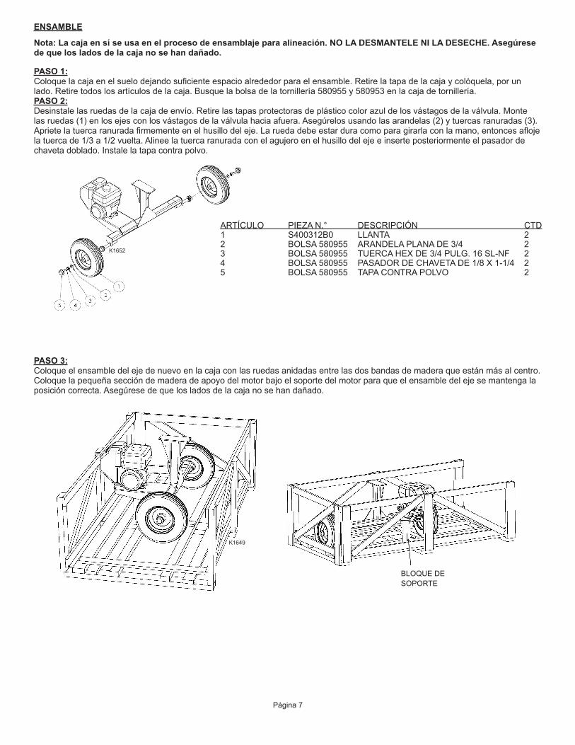
PARTIDOR DE TRONCOS CINÉTICO
INSTRUCCIONES DE ENSAMBLE Y OPERACIÓN
Manual del propietarioNúmero de modelo
580899
ADVERTENCIA: Todos los operadores deben leer este manual antes de operar este partidor de troncos. Siga las instrucciones de seguridad del manual y las etiquetas adheridas al producto. Si no lo hace podría causar lesiones graves o la muerte.
K1601


Contenido
Páginas
Importante información de seguridad 1–4
Uso previsto 1
Equipo de protección personal 1
Calcomanías de seguridad 2
Seguridad general 3
Área de trabajo 3
Preparación de los troncos 3
Operación del partidor de troncos 3
Mantenimiento general 4
Seguridad en el lugar de trabajo 4
Seguridad del remolque 4
Instrucciones de ensamble 5–13
Piezas de reemplazo 14–19
Instrucciones de operación 20–21
Remolque 22
Información de servicio por garantía 23
Especificaciones Contraportada


Este es el SÍMBOLO DE ALERTA DE SEGURIDAD. Se usa para advertirle sobre posibles riesgos de lesiones personales. Siga todos los mensajes de seguridad que aparecen después de este símbolo para evitar posibles lesiones o la muerte.
ANTES de operar este partidor de troncos, asegúrese de usar equipo de seguridad como gafas o anteojos de seguridad, zapatos conpuntadeaceroyguantesajustados(sinpuñosflojosnicordones).Siempreuseunaparatodeprotecciónauditivaaloperarestepartidordetroncos.
NUNCA use ropa floja ni joyería que pueda quedar atrapada en las piezas en movimiento del partidor de troncos. Mantenga la ropa y el cabello lejos de las piezas en movimiento al operar este partidor de troncos.
NUNCAuseestepartidordetroncosparaotrospropósitosquenoseanpartirmadera.Estádiseñadoparaesteuso solamente. Cualquierotrousopuedecausarlesionesgravesolamuerte.
EQUIPO DE PROTECCIÓN PERSONAL
USO PREVISTO
Página 1
ADVERTENCIA: Lea y entienda completamente todas las instrucciones de este manual y en las calcomanías de seguridad antes de ensamblar u operar este partidor de troncos. Si no lo hace podría causar lesiones graves o la muerte. No permita que nadie que no haya leído este manual opere este partidor de troncos. Al igual que con todo el equipo eléctrico, un partidor de troncos puede ser peligroso si se ensambla o se usa incorrectamente. No opere este partidor de troncos si tiene alguna pregunta relacionada con la operación segura. Para obtener respuestas a cualquier pregunta, llame a nuestro departamento de soporte técnico al 1-800-525-8322.
IMPORTANTE INFORMACIÓN DE SEGURIDAD

NÚMERO DE PIEZA: 580386UBICACIÓN: PARTE SUPERIOR DEL BRAZO, DEBAJO DEL PROTECTOR
CALCOMANÍAS DE SEGURIDAD
Asegúresedequetodaslascalcomaníasdeseguridadestánenbuenascondicionesyseanlegibles.Siemprereemplacelascalcomaníasquefaltenoestándeterioradas.ComuníqueseaSpeeCoal1-800-525-8322sinecesitacalcomaníasdereemplazo.
NÚMERO DE PIEZA: 580388UBICACIÓN: PARTE SUPERIOR DEL PROTECTOR
NÚMERO DE PIEZA: 580387UBICACIÓN: PARTE SUPERIOR DE LA LENGÜETA
NÚMERO DE PIEZA: 581696UBICACIÓN: PARTE SUPERIOR DEL PROTECTOR
NÚMERO DE PIEZA: S52062500UBICACIÓN: PARTE LATERAL DE LA LENGÜETA
NÚMERO DE PIEZA: S52069100UBICACIÓN: PARTE DELANTERA DEL SOPORTE DE GIRO (1), LADOS DEL BRAZO (2)
Página 2
NÚMERO DE PIEZA: 584052UBICACIÓN: BRAZO LATERAL, HACIA LA PARTE TRASERA
IMPORTANTE INFORMACIÓN DE SEGURIDAD

SEGURIDAD GENERAL
• SIEMPRE mantengaelmanualdeloperadorcercaparareferencia.Vuelvaaleerelmanualperiódicamente.• SIEMPRE establezca una zona de seguridad que restrinja el paso a espectadores a un radio de 10 pies alrededor del partidor
detroncoscuandoestéenfuncionamiento.• SIEMPRE asegúrese de que todos los operadores estén debidamente capacitados y hayan leído y entendido el manual del
operador.• SIEMPREopereelpartidordetroncosconlamenteclara,sininfluenciadealcohol,drogasnimedicamentos.• SIEMPREuseropaajustada,sincordones,hilosnijoyasquepuedanrepresentarunpeligrodequedaratrapado.• SIEMPREutilicelaropayelpelolejosdelaspiezasmovibles.• SIEMPREutiliceprotectoresdeseguridaddurantelaoperación.• NUNCAmuevamanualmenteelpartidorenunapendienteascendenteodescendente.
PREPARACIÓN DE LOS TRONCOS
ÁREA DE TRABAJO
• SIEMPRE opereestepartidordetroncosenunasuperficiefirmeyplana.• SIEMPREusecalzadoconlatracciónadecuada.• SIEMPREopereelpartidordetroncosenunáreaabierta.(Losvaporesdelescapecontienenmonóxidodecarbonoquepuede
sermortalsiseinhala).• SIEMPRE opereelpartidordetroncosenunasuperficieplana.(Operarenunapendientepuedeocasionarqueelpartidorde
troncosvuelqueoquelostroncossecaigan).• SIEMPREacuñelasruedasadecuadamenteparaevitarqueelpartidordetroncossemuevadurantelaoperación.• SIEMPREopereelpartidordetroncosduranteeldíaobajounabuenafuentedeluzartificial.• SIEMPREmantengalimpiaeláreadetrabajo.Retireinmediatamentelamaderapartidaqueestáalrededordesupartidorde
troncos para que no tropiececonesta.
OPERACIÓN DEL PARTIDOR DE TRONCOS
El partidor de troncos está diseñado para un solo operador, quien se para en las “zonas del operador”, utilizando la mano más cerca del tronco para operar el pestillo de seguridad y la otra mano para presionar lamanijadecontrol.Sielpartidordetroncosnoseoperaenestaposiciónpuedecausarlesionesgravesolamuerte.
• SIEMPREcargueeltroncoenelbrazohaciaarribacontralacuña.• SIEMPREseacuidadosoalmoverolevantarelpartidordetroncos.Pidaayudasilaunidadesmuypesadaparaquelamueva
solo.• SIEMPREacuñelasruedasadecuadamenteparaevitarqueelpartidordetroncossemuevadurantelaoperación.• NUNCAcoloquelasmanos,laspartesdelcuerponilaropadebajodelosprotectoresdurantelaoperación.Laspartesmovibles
puedendejarloatrapado.• SEPAcómodetenerelpartidordetroncosydesacoplarloscontrolesantesdeoperarlo.• NUNCA coloque las manos ni los pies entre el partidor y la cuña de corte durante el movimiento hacia adelante o en reversa ya
queestopodríacausarlesionesgravesolamuerte.• NUNCA seapoyeniseparesobreelpartidordetroncosdurantelaoperación.• NUNCAalcanceniseinclinesobreelpartidordetroncospararecogeruntronco.• NUNCAintentepartirdostroncosunosobreelotro.• NUNCAintentepartiruntroncotransversalmente.• NUNCAintentecargarsupartidordetroncoscuandoelcilindroolacuñaestánenmovimiento.• NUNCAusesupie,unacuerdaounaextensiónparaoperarloscontroles.Solopuedeusarambasmanos.• NUNCAmuevaelpartidordetroncosconelmotorfuncionando.• SIEMPRE apagueelmotorinclusosidejaelpartidordetroncosduranteunperíodocorto.• NUNCAtoqueelsilenciadoryotrasáreascalientesdelmotordurantelaoperación.Espereaqueelmotorenfríe.• SIEMPRE asegúrese de que el motor esté apagado mientras realice la limpieza de rutina para eliminar desechos del partidor,
eláreadetrabajoydelmotor.• SIEMPRE asegúresedequelapataestéaseguradaenposiciónhaciaabajo.• SIEMPRE asegúresedequelalengüetaestéretraídatotalmenteantesdelaoperacióndelpartidor.• NUNCAuseestepartidordetroncosparaotrospropósitosquenoseanpartirmadera.
Página 3
Lainobservanciadeestasinstruccionespuededarporresultadolesionesgravesolamuerte.
K1602
ZONA DEL OPERADOR
IMPORTANTE INFORMACIÓN DE SEGURIDAD
Ambosextremosdeltroncosedebencortartanrectoscomoseaposibleparaayudaraevitarqueeltroncoseresbaledelpartidordurantelaoperación.Nopartalostroncosauntamañomayorde24pulgadasdelargo.

• NUNCAoperesupartidordetroncossiestáencondiciónmecánicadeficienteonecesitareparación.• NUNCAmodifiquesupartidordetroncosdeningunamanera.Talesalteracionespuedencausarquesupartidordetroncossea
inseguroyanularánlagarantía.• NUNCAmanipuleelmotorparaquefuncioneavelocidadesexcesivas.Lavelocidadmáximadelmotorlaestablecepreviamenteel
fabricanteyestádentrodeloslímitesdeseguridad.Consulteelmanualdelpropietario.Alterarlaconfiguracióndelavelocidadestoanulalagarantíadelfabricante.
• SIEMPRE realicetodoslosprocedimientosdemantenimientorecomendadosantesdeusarsupartidordetroncos.• SIEMPREremplacetodaslaspiezasdañadasodesgastadasdeinmediato.• SIEMPREretireelcabledelabujíaantesderealizarcualquierserviciooreparaciónensupartidordetroncos.• SIEMPREreviseelniveldelaceitedelmotorantesdelaoperación.• TODASlaspiezasdereemplazodebencumplirconlasespecificacionesdelfabricante.• PERIÓDICAMENTEcoloqueunapequeñacantidaddegrasaenlapartesuperiordelacremallera.• PERIÓDICAMENTE limpietodaslasastillasydesechosdemaderadelosdientesdelacremallerayvuelvaaaplicargrasa.• EN CADA TEMPORADAengraseloscojinetesdelpiñón.• PERIÓDICAMENTErevisequetodaslastuercas,pernosytornillosesténapretadosantesdelaoperación.• SIEMPRE revise la correa de transmisión antes de usarla, para ver su condición, si está desgastada o si la tensión de la correa
eslaadecuada.• PERIÓDICAMENTElimpieyengraselevementelapartesuperiordelbrazo.• SIEMPRE remojeelcojinetedebroncedelembragueenaceitelivianoaliniciodecadaestaciónydespuésdecada100horasdeuso.• VARIAS veces durante la estación de partidor de troncos revise que el cojinete de elevación de la cremallera esté limpio y pueda
girarlibremente.Delocontrario,limpieelcojineteyelpernodesoporteycoloquegrasaenelpernodesoportehastaqueelcojinetegirelibremente.
• SIEMPRE revise todas las regulaciones locales y estatales respecto al remolque, concesión de licencias y luces antes de remolcarsupartidordetroncos.
• SIEMPRE revise antes de remolcar para asegurarse que el partidor de troncos está conectado de manera correcta y segura al vehículoderemolqueyquelascadenasdeseguridadestánaseguradasalengancheoaladefensadelvehículoconsuficienteholguraparapermitirlosgiros.Siempreuseunabolade2pulgadas,ClaseIconestepartidordetroncos.
• SIEMPREconfirmesielacopladorestáajustadocadavezantesderemolcarydespuésderemolcarlopor50millas.• SIEMPREdesconectesupartidordetroncosdelvehículoderemolqueantesdeoperarlo.• SIEMPREtengacuidadoalretrocederconsupartidordetroncosenremolque.Podríacolear.• SIEMPREdejeespaciosuficienteparasupartidordetroncosalgirar,estacionarse,atravesarinterseccionesyentodaslas
situacionesdemanejo.• SIEMPRE cierrelaválvuladecombustibleenelmotorenlaposición“OFF”(Apagado)antesderemolcarelpartidordetroncos.
Sinolohacepodríacausarundesbordamientodelmotor.• SIEMPREusecadenasdeseguridadalremolcarsupartidordetroncos.• SIEMPREreemplacelabolaoelacopladorsiestádañadoomuydesgastado.• NUNCAexceda45mphalremolcarsupartidordetroncos.Remolcarelpartidordetroncosavelocidadesmayoresque45mph
puederesultarenlapérdidadecontrol,dañoalequipo,lesionesgravesolamuerte.Ajustelavelocidadderemolqueparaelterrenoylascondiciones.
• SIEMPRE seaextremadamenteprecavidocuandoremolqueenterrenosdifíciles,especialmenteencrucesdelferrocarril.• NUNCAllevecarganimaderasobresupartidordetroncos.• NUNCAdejequenadiesesientenisesubasobreelpartidordetroncos.• NUNCAexcedalacapacidaddepesodeloslímitesdebolaocargadelacoplador.• SIEMPREextiendatotalmenteyasegureadecuadamentelalengüetapararemolcar.• SIEMPREreviselacondicióndelosneumáticosyelinfladoadecuado.Noremolquelaunidadsilosneumáticosestáninflados
inadecuadamenteosiestándañados.• SIEMPRE asegúresedequelapataestéaseguradaenposiciónhaciaarribaantesderemolcar.
MANTENIMIENTO GENERAL
SEGURIDAD EN EL LUGAR DE TRABAJO
SEGURIDAD DEL REMOLQUE
• NUNCAoperesupartidordetroncoscercadellamasochispas.• NUNCAlleneeltanquedegasolinamientraselmotorestácalienteoenfuncionamiento.• SIEMPRE apague el motor y dejequeenfríeelmotorantesderellenardecombustible.• NUNCAfumemientrasestéoperandoollenandodecombustibleelpartidordetroncos.Losvaporesdelcombustiblepueden
explotarfácilmente.• NUNCAalmacenegasolinaeninterioresocercadeunequipodecalefacción.• SOLO llene de combustible su partidor de troncos en un área aislada en donde no haya vapores de combustibles ni
combustiblesderramados.• SIEMPREreemplacelatapadelagasolinademanerasegura.Sisederramógasolina,muevaelpartidordetroncoslejosdel
áreadederrameyevitecrearcualquierfuentedeigniciónhastaqueelcombustiblederramadosehayalimpiadoadecuadamente.• SIEMPRElleveconustedunextintordeincendiosdeClaseBcuandoopereelpartidordetroncosenáreassecas,como
medidadeprecaucióncontraunaposiblecombustión.• SIEMPREvacíeeltanquedecombustibleantesdelalmacenamiento,paraevitarelriesgodeunposibleincendio.• SIEMPREalmacenelagasolinaadecuadamenteenunrecipienteautorizado.• NUNCAdejequeseacumulendesechosoastillasdemaderaenelmotor.NOTA IMPORTANTE(extintordechispas):Comomedidadeprecaucióncontraposibleschispasvolantes,siemprelleveconsigounextintordeincendiosClaseBcuandoopereelpartidordetroncosenáreassecas.Estepartidordetroncosestáequipadoconunmotordecombustióninternaynosedebe usar en o cerca de cualquier terreno forestal, cubierto con arbustos o cubierto con césped en estado natural a menos que el sistemadeescapedelmotorestéequipadoconunextintordechispasquecumplaconlasleyeslocalesoestatalesvigentes(silashay).Siseusaunextintordechispas,eloperadordebemantenerloenbuenestadodefuncionamiento.EnelestadodeCalifornia,laleyrequiereunextintordechispas.Otrosestadostienenleyessimilares.Lasleyesfederalesaplicanaterrenosfederales.Unsilenciadordelextintordechispasesopcionalyestádisponiblecomounaccesorioconsudistribuidordelmotormáscercano.Siemprereviselosrequisitoslegalesensuárea.
Página 4
IMPORTANTE INFORMACIÓN DE SEGURIDAD

ARTÍCULO PIEZA N.° DESCRIPCIÓN CTD
1 578727 EJE, CINÉTICO, ENSAMBLE 12 581740 BRAZO, NEGRO, PLACA DE EMPUJE, CINÉTICO, ENSAMBLE 13 581492 PATA, CINÉTICO, PARTIDOR 14 S400312B0 PIEZA DEL PARTIDOR, NEUMÁTICO CON COPA, SELLO, COJINETE 25 578705 LENGÜETA, CINÉTICA, ENSAMBLE 16 580851 MESA, CINÉTICA, SPEECO RED, WDMT 17 575856 CORREA, ACCESO, A74 28 581493 CUBIERTA, CORREA, CON ETIQUETA, CINÉTICA 19 581695 PROTECTOR, SPEECO, IZQUIERDO, CON ETIQUETA, CINÉTICA 110 581555 PROTECTOR, SPEECO, DERECHO, CON ETIQUETA, CINÉTICA 111 578723 MANIJA, SUPERIOR, NEGRA, CINÉTICA, ENSAMBLE 1
INSTRUCCIONES DE ENSAMBLE
NOTA:Desempaquelacajayrevisecuidadosamentesucontenidoantesdeempezaraensamblar.
Página 5
K1603

BOLSA 580953 PiezaN.° Descripción CTD12 584306 PERNO, HEX, 3/8-16X1-1/2, GRADO 8 413 575805 TUERCA, HEXAGONAL, 3/8-16 UNC X 21/64, GR 8 414 838 ARANDELA, BLOQUEO, 3/8 DI, ACERO GALVANIZADO 4
Tornillería en bolsa
BOLSA 580951 PiezaN.° Descripción CTD1 S071011C0 PASADORDECHAVETADE1/2X41/4Pulg. 12 576044 PASADOR, RANURADO, DIÁ 1/2, 3-3/4 LG 13 584305 PERNO, HEX, 1/2-13 X 3-3/4, GR 5 14 573552 TUERCA, NYLOCK, 1/2-13 UNC X 19/32, GR 5 15 576755 CLIP, E-ESTILO, 1/2, AMARILLO ZINC-STL 1
1
2
3
4
5
6
7
8
9
10
11
12
13
14
15
16
17
18
19
20
21
22
23
24
BOLSA 580952 PiezaN.° Descripción CTD6 575828 TORNILLO, PHILIPS, 1/4-20 X 1-1/4 87 2457 1/4NCx3/4HHCSGR5 48 5336 ARANDELA PLANA ESTÁNDAR DE 1/4 89 1985 ARANDELA, BLOQUEO, 1/4 DI, ACERO GALVANIZADO 1010 583332 CONTRATUERCA, BLOQUEO, 1/4-20 UNC X 7/32, GR 2 211 570789 TUERCA, HEXAGONAL, 1/4-20 UNC X 7/32, GR 5 2
BOLSA 580954 PiezaN.° Descripción CTD15 20973 PERNO, CARRO, 3/8-16 X 1-1/4, GR 5 (plateado) 416 584306 PERNO, HEXAGONAL, 3/8-16X1-1/2, GRADO 8 (amarillo) 217 570793 TUERCA, HEX, 3/8-16 UNC X 21/64, GR 5 (plateada) 418 575805 TUERCA, HEXAGONAL, 3/8-16 UNC X 21/64, GR 8 (amarilla) 219 21757 ARANDELA, PLANA, 3/8, ACERO GALVANIZADO 420 838 ARANDELA, BLOQUEO, 3/8 DI, ACERO GALVANIZADO 6
BOLSA 580955 PiezaN.° Descripción CTD21 S40033200 TAPA, LLANTA Y RUEDA DE ALTA VELOCIDAD 222 5849 TUERCA HEXAGONAL RANURADA DE 3/4 NF 223 2864 3/4 TIPO DE ARANDELA PLANA A NAR DE 3/4 224 5241 PASADOR DE CHAVETA DE 1/8 X 1-1/4 2
Página 6
K1605
K1606
K1607
K1608
K1604
ENSAMBLE
Página 7
Nota: La caja en sí se usa en el proceso de ensamblaje para alineación. NO LA DESMANTELE NI LA DESECHE. Asegúrese de que los lados de la caja no se han dañado.
PASO 1:Coloquelacajaenelsuelodejandosuficienteespacioalrededorparaelensamble.Retirelatapadelacajaycolóquela,porunlado.Retiretodoslosartículosdelacaja.Busquelabolsadelatornillería580955y580953enlacajadetornillería.PASO 2:Desinstalelasruedasdelacajadeenvío.Retirelastapasprotectorasdeplásticocolorazuldelosvástagosdelaválvula.Montelasruedas(1)enlosejesconlosvástagosdelaválvulahaciaafuera.Asegúrelosusandolasarandelas(2)ytuercasranuradas(3).Aprietelatuercaranuradafirmementeenelhusillodeleje.Laruedadebeestarduracomoparagirarlaconlamano,entoncesaflojelatuercade1/3a1/2vuelta.Alineelatuercaranuradaconelagujeroenelhusillodelejeeinserteposteriormenteelpasadordechavetadoblado.Instalelatapacontrapolvo.
PASO 3:Coloqueelensambledelejedenuevoenlacajaconlasruedasanidadasentrelasdosbandasdemaderaqueestánmásalcentro.Coloque la pequeña sección de madera de apoyo del motor bajo el soporte del motor para que el ensamble del eje se mantenga la posicióncorrecta.Asegúresedequelosladosdelacajanosehandañado.
BLOQUE DE SOPORTE
K1649
K1652
ARTÍCULO PIEZAN.° DESCRIPCIÓN CTD1 S400312B0 LLANTA 22 BOLSA 580955 ARANDELA PLANA DE 3/4 23 BOLSA580955 TUERCAHEXDE3/4PULG.16SL-NF 24 BOLSA 580955 PASADOR DE CHAVETA DE 1/8 X 1-1/4 25 BOLSA 580955 TAPA CONTRA POLVO 2
Página 8
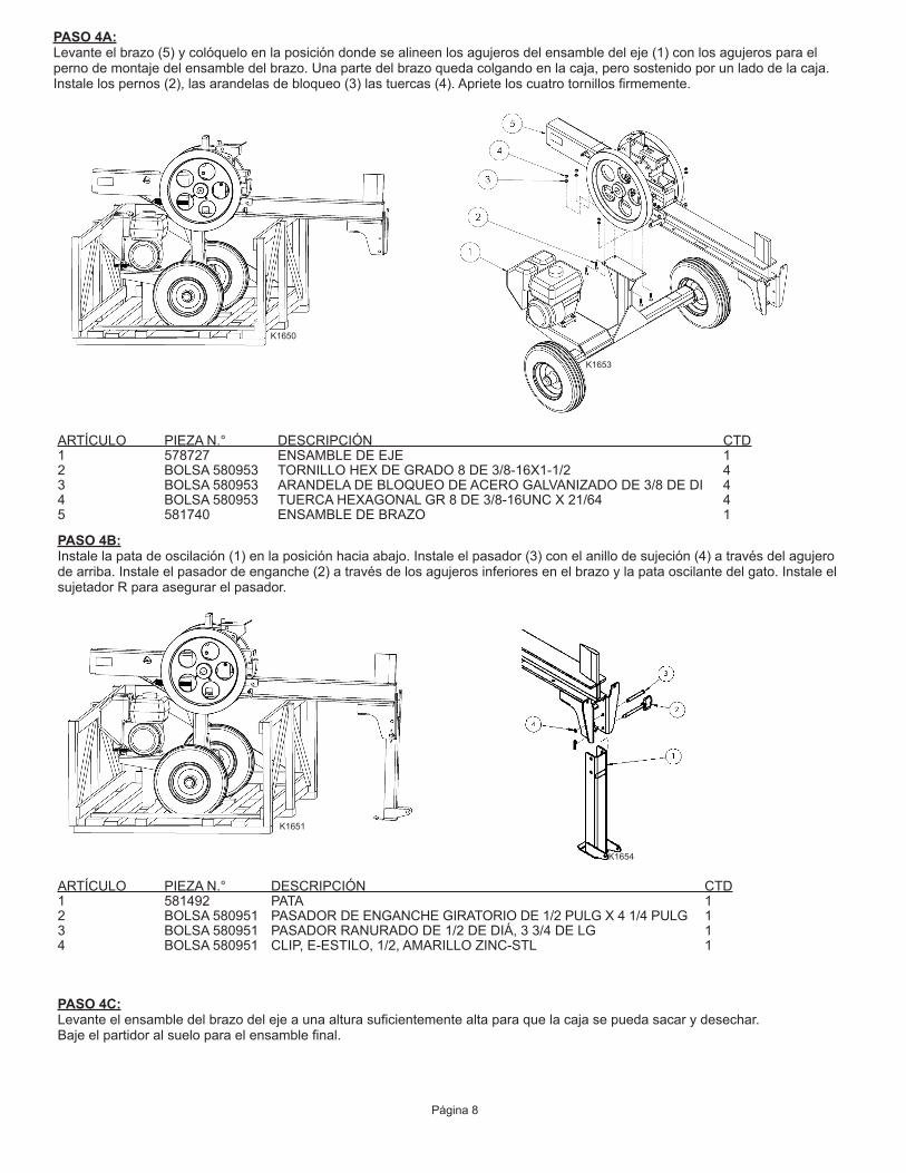
PASO 4A:Levante el brazo (5) y colóquelo en la posición donde se alineen los agujeros del ensamble del eje (1) con los agujeros para el pernodemontajedelensambledelbrazo.Unapartedelbrazoquedacolgandoenlacaja,perosostenidoporunladodelacaja.Instalelospernos(2),lasarandelasdebloqueo(3)lastuercas(4).Aprieteloscuatrotornillosfirmemente.
PASO 4B:Instalelapatadeoscilación(1)enlaposiciónhaciaabajo.Instaleelpasador(3)conelanillodesujeción(4)atravésdelagujerodearriba.Instaleelpasadordeenganche(2)atravésdelosagujerosinferioresenelbrazoylapataoscilantedelgato.InstaleelsujetadorRparaasegurarelpasador.
ARTÍCULO PIEZAN.° DESCRIPCIÓN CTD1 578727 ENSAMBLE DE EJE 12 BOLSA 580953 TORNILLO HEX DE GRADO 8 DE 3/8-16X1-1/2 43 BOLSA 580953 ARANDELA DE BLOQUEO DE ACERO GALVANIZADO DE 3/8 DE DI 44 BOLSA 580953 TUERCA HEXAGONAL GR 8 DE 3/8-16UNC X 21/64 45 581740 ENSAMBLE DE BRAZO 1
ARTÍCULO PIEZAN.° DESCRIPCIÓN CTD1 581492 PATA 12 BOLSA 580951 PASADOR DE ENGANCHE GIRATORIO DE 1/2 PULG X 4 1/4 PULG 13 BOLSA 580951 PASADOR RANURADO DE 1/2 DE DIÁ, 3 3/4 DE LG 14 BOLSA 580951 CLIP, E-ESTILO, 1/2, AMARILLO ZINC-STL 1
PASO 4C:Levanteelensambledelbrazodelejeaunaalturasuficientementealtaparaquelacajasepuedasacarydesechar.Bajeelpartidoralsueloparaelensamblefinal.
K1650
K1651
K1653
K1654
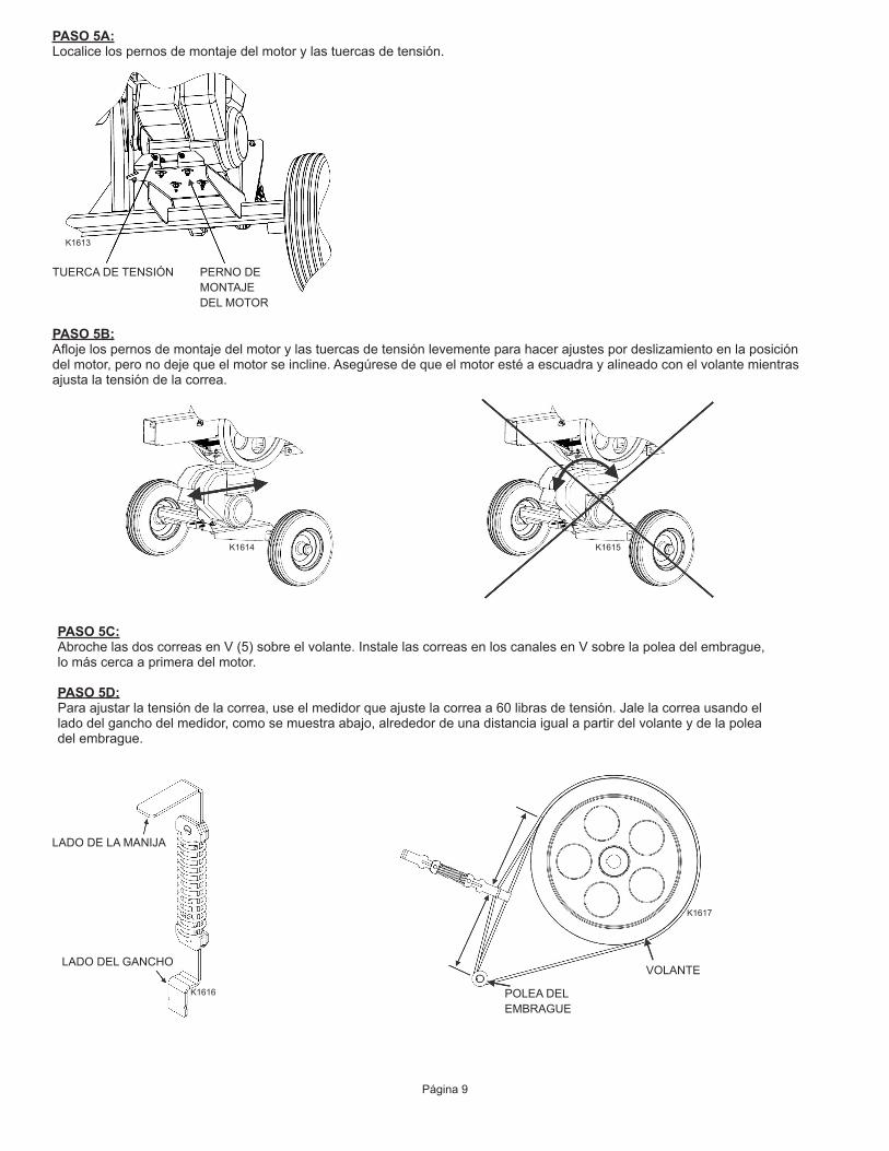
PASO 5A:Localicelospernosdemontajedelmotorylastuercasdetensión.
Página 9
TUERCA DE TENSIÓN PERNO DE MONTAJE DEL MOTOR
PASO 5B:Aflojelospernosdemontajedelmotorylastuercasdetensiónlevementeparahacerajustespordeslizamientoenlaposicióndelmotor,peronodejequeelmotorseincline.Asegúresedequeelmotorestéaescuadrayalineadoconelvolantemientrasajustalatensióndelacorrea.
PASO 5C:AbrochelasdoscorreasenV(5)sobreelvolante.InstalelascorreasenloscanalesenVsobrelapoleadelembrague,lomáscercaaprimeradelmotor.
PASO 5D:Paraajustarlatensióndelacorrea,useelmedidorqueajustelacorreaa60librasdetensión.Jalelacorreausandoellado del gancho del medidor, como se muestra abajo, alrededor de una distancia igual a partir del volante y de la polea delembrague.
LADO DE LA MANIJA
LADO DEL GANCHO
POLEA DEL EMBRAGUE
VOLANTE
K1613
K1614 K1615
K1616
K1617
Página 10
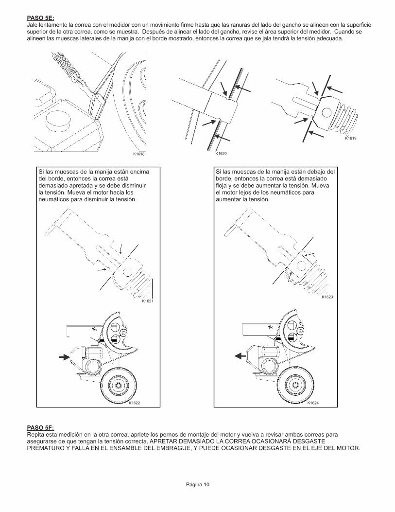
PASO 5E:Jalelentamentelacorreaconelmedidorconunmovimientofirmehastaquelasranurasdelladodelganchosealineenconlasuperficiesuperiordelaotracorrea,comosemuestra.Despuésdealinearelladodelgancho,reviseeláreasuperiordelmedidor.Cuandosealineenlasmuescaslateralesdelamanijaconelbordemostrado,entonceslacorreaquesejalatendrálatensiónadecuada.
Si las muescas de la manija están encima del borde, entonces la correa está demasiado apretada y se debe disminuir latensión.Muevaelmotorhacialosneumáticosparadisminuirlatensión.
Si las muescas de la manija están debajo del borde, entonces la correa está demasiado flojaysedebeaumentarlatensión.Muevael motor lejos de los neumáticos para aumentarlatensión.
PASO 5F:Repita esta medición en la otra correa, apriete los pernos de montaje del motor y vuelva a revisar ambas correas para asegurarsedequetenganlatensióncorrecta.APRETARDEMASIADOLACORREAOCASIONARÁDESGASTEPREMATUROYFALLAENELENSAMBLEDELEMBRAGUE,YPUEDEOCASIONARDESGASTEENELEJEDELMOTOR.
K1618 K1620
K1619
K1622
K1621K1623
K1624

ARTÍCULO PIEZAN.° DESCRIPCIÓN CTD1 581493 CUBIERTA DE LA CORREA 12 BOLSA 580952 PERNO HEXAGONAL 1/4-20 UNC X 3/4, GR 5 23 BOLSA 580952 ARANDELA DE SEGURIDAD ACERO GALVANIZADO 1/4 DI 24 BOLSA 580952 TUERCA HEXAGONAL 1/4-20 UNC X 7/32, GR 5 25 575856 CORREA 2
PASO 5G:Instale los protectores de las correas (1) de la parte de atrás, sobre las correas y apriete los pernos manualmente (2) con las arandelas(3)ylastuercas(4)ensulugar.Cuandosehayaninstaladolosdospernos,aprietetodoslospernosfirmemente.
Página 11
UBICACIÓN DEL MONTAJE DE LAS CUBIERTAS DE LAS CORREAS
K1625
ARTÍCULO PIEZAN.° DESCRIPCIÓN CTD1 BOLSA 580954 PERNO DE CARRO 3/8-16 X 1-1/4, GR 5 42 BOLSA 580954 PERNO HEXAGONAL DE 3/8-16 X 1-1/2, GRADO 8 23 BOLSA 580954 TUERCA HEXAGONAL 3/8-16 UNC X 21/64, GR 8 24 580851 MESA 15 BOLSA 580954 TUERCA HEXAGONAL 3/8-16 UNC X 21/64, GR 5 46 BOLSA 580954 ARANDELA DE BLOQUEO ACERO GALVANIZADO 3/8 DI 67 BOLSA 580954 ARANDELA PLANA DE ACERO GALVANIZADO 3/8 4
PASO 6:Muevalamesa(4)hastacolocarlaensulugardeslizándoladesdeelfrentedelensambledelbrazo.Instalelospernos(1y2),laarandela plana (7), la arandela de bloqueo (6) y la tuerca (3) y (5) en cada perno como esté instalado y apriete los pernos con las manos.Aprietetodoslospernosfirmemente.
K1655

Página 12
PASO 8:Elprotectordelvolanteprincipal(1y2)vieneendosmitades.Primero,roteelsoporteangularsuperiorhastaquelleguealaposiciónverticalyasegureconpernos(6)ytuercascenterlock(7).Instaleelprotectorempezandodelladoopuestodelmotor.Asegureelescudoalaunidadusandotornillos(5),arandelasplanas(3)yarandelasdebloqueo(4).Aprietefirmementetodalatornilleríaquesujetaelprotector.
ARTÍCULO PIEZAN.° DESCRIPCIÓN CTD1 581555 PROTECTOR DERECHO 12 581695 PROTECTOR IZQUIERDO 13 BOLSA 580952 ARANDELA PLANA DE ACERO GALVANIZADO 1/4 84 BOLSA 580952 ARANDELA DE BLOQUEO ACERO GALVANIZADO 1/4 DI 85 BOLSA 580952 TORNILLO, PHILIPS 1/4-20 X 1-1/4 86 BOLSA 580952 PERNO HEXAGONAL 1/4-20 UNC X 1, GR 5 27 BOLSA 580952 TUERCA CNTLOCK 1/4-20 UNC X 7/32, GR 2 2
SOPORTE ANGULAR
K1628
PASO 7:Desliceelensambledelalengüeta(1)enlaunidad,desdeelfrente.Insertelospernos(3)atravésdelalengüetayasegurelatuercadeseguridaddenilón(2).
ARTÍCULO PIEZAN.° DESCRIPCIÓN CTD1 578705 ENSAMBLE DE LENGÜETA 12 BOLSA 580951 TUERCA NYLOCK 1/2-13 UNC X 19/32, GR 5 13 BOLSA 580951 PERNO HEXAGONAL 1/2-13 X 3-3/4, GR 5 1
K1626
(Tablaretiradaparamostrarlosdetalles.)

PASO 9:Atornillelamanijadecontrol(1)enposición,enlapartesuperiordelaunidad.Asegurelamanijadeseguridadensulugar,apretandolatuercadebloqueosobrelamanijadecontrol.
NOTAS
Página 13
ARTÍCULO PIEZAN.° DESCRIPCIÓN CTD1 578723 ENSAMBLE DE MANIJA 1
K1629
PIEZAS DE REEMPLAZO
Página 14
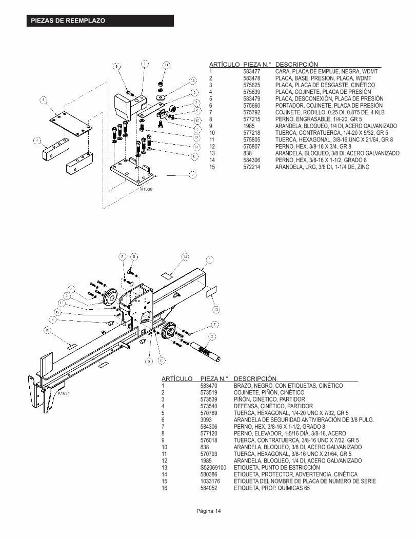
ARTÍCULO PIEZAN.° DESCRIPCIÓN 1 583470 BRAZO, NEGRO, CON ETIQUETAS, CINÉTICO2 573519 COJINETE, PIÑÓN, CINÉTICO3 573539 PIÑÓN, CINÉTICO, PARTIDOR4 573540 DEFENSA, CINÉTICO, PARTIDOR5 570789 TUERCA, HEXAGONAL, 1/4-20 UNC X 7/32, GR 56 3093 ARANDELA DE SEGURIDAD ANTIVIBRACIÓN DE 3/8 PULG.7 584306 PERNO, HEX, 3/8-16 X 1-1/2, GRADO 88 577120 PERNO, ELEVADOR, 1-5/16 DIÁ, 3/8-16, ACERO9 576018 TUERCA, CONTRATUERCA, 3/8-16 UNC X 7/32, GR 510 838 ARANDELA, BLOQUEO, 3/8 DI, ACERO GALVANIZADO11 570793 TUERCA, HEXAGONAL, 3/8-16 UNC X 21/64, GR 512 1985 ARANDELA, BLOQUEO, 1/4 DI, ACERO GALVANIZADO13 S52069100 ETIQUETA, PUNTO DE ESTRICCIÓN14 580386 ETIQUETA, PROTECTOR, ADVERTENCIA, CINÉTICA15 1033176 ETIQUETA DEL NOMBRE DE PLACA DE NÚMERO DE SERIE 16 584052 ETIQUETA, PROP. QUÍMICAS 65
K1630
K1631
ARTÍCULOPIEZAN.° DESCRIPCIÓN 1 583477 CARA, PLACA DE EMPUJE, NEGRA, WDMT2 583478 PLACA, BASE, PRESIÓN, PLACA, WDMT3 575625 PLACA, PLACA DE DESGASTE, CINÉTICO4 575639 PLACA, COJINETE, PLACA DE PRESIÓN5 583479 PLACA, DESCONEXIÓN, PLACA DE PRESIÓN6 575660 PORTADOR, COJINETE, PLACA DE PRESIÓN7 575792 COJINETE, RODILLO, 0.25 DI, 0.875 DE, 4 KLB8 577215 PERNO, ENGRASABLE, 1/4-20, GR 59 1985 ARANDELA, BLOQUEO, 1/4 DI, ACERO GALVANIZADO10 577218 TUERCA, CONTRATUERCA, 1/4-20 X 5/32, GR 511 575805 TUERCA, HEXAGONAL, 3/8-16 UNC X 21/64, GR 812 575807 PERNO, HEX, 3/8-16 X 3/4, GR 813 838 ARANDELA, BLOQUEO, 3/8 DI, ACERO GALVANIZADO14 584306 PERNO, HEX, 3/8-16 X 1-1/2, GRADO 815 572214 ARANDELA, LRG, 3/8 DI, 1-1/4 DE, ZINC
Página 15
ARTÍCULO PIEZAN.° DESCRIPCIÓN1 S40034600 PIEZA PARTIDOR, ACOPLADOR 2 CAN.2 583486 LENGÜETA, CON ETIQUETAS, CINÉTICA, ENSAMBLE3 565286 ARANDELA, PLANA, M10, ACERO GALVANIZADO4 565276 PERNO, HEXAGONAL, M10X1.5X120, GR 55 565275 PERNO, HEXAGONAL, M10X1.5X100, GR 56 S40032300 CADENA DE 20 ESLABONES CON GANCHO7 584307 TUERCA, NYLOCK, M10X1.5X10, CLS88 S52062500 ETIQUETA TRILINGÜE, ADVERTENCIA LENGÜETA
ARTÍCULO PIEZAN.° DESCRIPCIÓN1 583480 SOBRE CNT, ESLABÓN, CINÉTICO PARTIDOR, WDMT2 575704 COJINETE, RODILLO, 3/8 DI, 1-1/4 DE,3 576757 PERNO, RESALTO, 3/8 X 2-1/2, ACERO4 838 ARANDELA, BLOQUEO, 3/8 DI, ACERO GALVANIZADO5 574435 TUERCA, NYLOCK, 5/16-18 UNC X 11/32, GR 5
K1632
K1633

Página 16
ARTÍCULO PIEZAN.° DESCRIPCIÓN1 583482 MANIJA, CINÉTICO, PARTIDOR, WDMT2 576031 RESORTE, TORSIÓN, IZQUIERDO, MANIJA3 576032 RESORTE, TORSIÓN, DERECHO, MANIJA
ARTÍCULO PIEZAN.° DESCRIPCIÓN1 583490 EJE, 8 PULG., CINÉTICO, PARTIDOR, WDMT2 581582 MOTOR, KOHLER, SH2653 575523 EMBRAGUE, CINÉTICO, PARTIDOR4 S52029800 ETIQUETA, ENSAMBLADO EN LOS EE. UU.5 583491 KIT, TORNILLERÍA, MOTOR, CINÉTICO*NO SE INDICA EN EL DIBUJO
K1634
K1635
Página 17
ARTÍCULOPIEZAN.° DESCRIPCIÓN 1 583481 SOPORTE, CUBIERTA, CINÉTICO, ENSAMBLE2 3489 PERNO, HEX, 1/2-13 UNC X 3, GR 53 573520 RESORTE, CREMALLERA, CINÉTICO, PARTIDOR4 573528 CREMALLERA, CINÉTICO, PARTIDOR5 584334 PERNO, HEX, 3/8-16 UNC X 2-1/4, GR 56 575704 COJINETE, RODILLO, 3/8 DI, 1-1/4 DE,7 583484 ESLABÓN MEDIO, CINÉTICO, PARTIDOR8 576756 PASADOR, DE 2 RANURAS, 1/2 DIÁ, 4-1/2 LG9 573548 PERNO, RESALTO, 1/2 X 1, ACERO10 583485 BOTÓN DE SEGURIDAD, NEGRO, CINÉTICO11 575959 PASADOR, RANURADO, DIÁ 1/2, 4-1/4 LG12 576043 RESORTE, TORSIÓN, SEGURO, MANIJA13 576754 PASADOR, RANURADO, DIÁ 1/2, 3-1/2 LG14 573524 RESORTE, RETORNO, CINÉTICO, PARTIDOR15 2457 1/4NC x 3/4 HHCS GR 516 583332 CONTRATUERCA, BLOQUEO, 1/4-20 UNC X 7/32, GR 217 572670 VOLANTE, CINÉTICO18 574874 PIEZAS PRINCIPALES, 3/8 X 3/8 X 1-1/219 581797 TORNILLO, FIJACIÓN, CUADRADO 5/16-18 X 1-1/220 576755 CLIP, E-ESTILO, 1/2, AMARILLO ZINC-STL21 583483 MONTAJE, RESORTE, RETORNO, CINÉTICO22 572230 TUERCA, NYLOCK, 3/8-16 UNC X 29/64, GR 523 574454 TUERCA, NYLOCK, BRIDA, 3/8-16 UNC, GR 5
ARTÍCULO PIEZAN.° DESCRIPCIÓN1 583488 MESA, CINÉTICA, SPEECO RED, WDMT2 S400312B0 PIEZA DEL PARTIDOR, NEUMÁTICO CON COPA, SELLO, COJINETE3 583468 PROTECTOR, SPEECO, IZQUIERDO, CON ETIQUETA, CINÉTICA4 583469 PROTECTOR, SPEECO, DERECHO, CON ETIQUETA, CINÉTICA5 583489 PATA, CINÉTICA, PARTIDOR6 583487 CUBIERTA, CORREA, CON ETIQUETA, CINÉTICA
K1636
K1637

Página 18
ARTÍCULO PIEZAN.° DESCRIPCIÓN1 575856 CORREA, ACCESO A742 583466 MANIJA, SUPERIOR, NEGRA, CINÉTICA, ENSAMBLE3 583467 KIT, TORNILLERÍA, CUBIERTA, CINÉTICA4 583492 KIT, TORNILLERÍA, EJE, CINÉTICO5 583539 KIT, TORNILLERÍA, MESA, CINÉTICA6 581299 MANUAL, SPEECO, PARTIDOR, CINÉTICO7 584561 MEDIDOR, TENSIÓN, CINÉTICO8* 580382 LOGOTIPO SPEECO KINETIC9 580457 ETIQUETA, F UNCIONES, CINÉTICA* NO SE MUESTRA
ARTÍCULO PIEZAN.° DESCRIPCIÓN1 S071011C0 PASADOR DE CHAVETA DE 1/2 PULG. X 4 1/4 PULG2 576044 PASADOR, RANURADO, DIÁ 1/2, 3-3/4 LG3 576755 CLIP, E-ESTILO, 1/2, AMARILLO ZINC-STL4 584305 PERNO, HEX, 1/2-13 X 3-3/4, GR 55 573552 TUERCA, NYLOCK, 1/2-13 UNC X 19/32, GR 5
ARTÍCULO PIEZAN.° DESCRIPCIÓN1 S40033200 TAPA, LLANTA Y RUEDA DE ALTA VELOCIDAD2 5849 TUERCA HEXAGONAL RANURADA DE 3/4 NF3 2864 TIPO DE ARANDELA PLANA A NAR DE 3/44 5241 PASADOR DE CHAVETA DE 1/8 X 1-1/4
K1638
K1640
K1639
Página 19
ARTÍCULO PIEZAN.° DESCRIPCIÓN1 S52069100 ETIQUETA, PUNTO DE ESTRICCIÓN
ARTÍCULO PIEZAN.° DESCRIPCIÓN1 581696 ETIQUETA, BLOQUEO, MANIJA, CINÉTICA2 580388 ETIQUETA, MANIJA, CINÉTICA
NOTA:Despuésdereemplazarcualquierpieza,verifiqueelfuncionamientoadecuadodelamáquina.
K1641
K1642

ADVERTENCIA: NO PONGA LAS MANOS DEBAJO DEL PROTECTOR CUANDO EL MOTOR ESTÉ FUNCIONANDO. PARA HACER CUALQUIER AJUSTE, ESPERE POR LO MENOS TREINTA (30) SEGUNDOS PARA QUE EL VOLANTE SE DETENGAN DESPUÉS DE APAGAR EL MOTOR.
INSTRUCCIONES DE OPERACIÓN
ADVERTENCIA: CUANDO EL MOTOR ESTÉ FUNCIONANDO NO COLOQUE SUS MANOS EN NINGÚN MOMENTO ENTRE EL TRONCO, LA CUÑA Y EL CILINDRO. MANTENGA SUS MANOS LEJOS DE LAS PARTES MOVIBLES
ADVERTENCIA: NUNCA INTENTE PARTIR UN TRONCO TRANSVERSALMENTE
NOTA: Coloqueelpartidordetroncosenunáreadespejadayniveladayacuñelasruedas.NOTA: Revisetodoslosnivelesdefluidosyajustelosfluidosdereemplazoadecuadamentesiesnecesario,antesdearrancarel
motor.NOTA: Arranque el motor de acuerdo a las instrucciones de operación del fabricante del motor para el tipo de motor y deje que el
motoralcancelavelocidadtotaldeoperaciónantesdeusarlaunidad.NOTA: Cuandonoestéusandoelpartidor,cierrelaválvuladecombustibledeacuerdoalmanualdelfabricantedelmotor.NOTA: Remojeelcojinetedebroncedelembragueenaceitelivianoaliniciodecadaestaciónydespuésdecada100horasdeuso.
Página 20
ADVERTENCIA: Lea y entienda completamente todas las instrucciones de este manual y en las calcomanías de seguridad antes de ensamblar u operar este partidor de troncos. Si no lo hace podría causar lesiones graves o la muerte. No permita que nadie que no haya leído este manual opere este partidor de troncos. Al igual que con todo el equipo eléctrico, un partidor de troncos puede ser peligroso si se ensambla o se usa incorrectamente. No opere este partidor de troncos si tiene alguna pregunta relacionada con la operación segura. Para obtener respuestas a cualquier pregunta, llame a nuestro departamento de soporte técnico al 1-800-525-8322.
K1643
K1644

NOTA: Para todos los motores: Consulte el manualdeoperacióndelfabricante.Asegúrese de que el motor tiene aceite ycombustibleantesdearrancar.
MotoresKOHLER:ConsulteelmanualdelmotorKohlerparaverlasrecomendacionessobreelaceite,elarranqueyelmantenimiento.
RECOMENDACIONES DE ACEITE DE MOTOR (Kohler SH265)ConsulteelmanualdelmotorKohlerparaverlasrecomendacionessobreelaceite,elarranqueyelmantenimiento.Paratemperaturassobre32gradosFahrenheit,useunaceite10W-30.Paratemperaturasdebajode32gradosFuseunaceiteSAE5W-20oSAE5W-30.ElusodeaceiteSAE30Wdebajode40gradosFahrenheitcausaráunarranqueduroyposibledañoalaaberturadelmotor.Elusodeaceitemultigradopuedeaumentarelconsumodeaceite.Lacapacidaddeaceiteesdealrededorde0.63qt.(0.60l).
INSTRUCCIONES DE ARRANQUE (Kohler SH265)• Muevalapalancadecombustiblealaposición“ON”(Encendido).• Paraunmotorfrío,pongaelcontroldelaceleradoralamitadentre“SLOW”(Lento)y“FAST”(Rápido).Coloqueelcontroldel
obturadorenlaposición“ON”(Encendido).• GireelinterruptorON/OFF(Encendido/apagado)alaposición“ON”(Encendido).Jalelentamentelamanijadearranquejusto
pasandolacompresión.¡PARE!Regreselamanijadearranque.Jalefirmementeconunmovimientoconstanteysuavehastaquearranque.
• Regresegradualmenteelcontroldelobturadoralaposición“OFF”(Apagado)despuésdequeelmotorarranqueycaliente.• Paraunmotorcaliente,pongaelcontroldelaceleradorentre“SLOW”(Lento)y“FAST”(Rápido).Unmotorcalienteporlo
generalnorequiereelobturador.
DETENER EL MOTOR• Deserposible,retirelacarga.• Muevaelcontroldelaceleradoralaposiciónderalentí“SLOW”(lento)o“LOW”(bajo).• Gire el interruptor de la llave o el interruptor on/off (encendido/apagado) a off (apagado) o mueva el acelerador a la posición
“STOP”(parar),siestáincluido.• Cierrelaválvuladecierredecombustible.
OPERACIÓN DEL MOTOR
OPERACIÓN DEL PARTIDOR
1. Desconecteelpartidordetroncossiestáconectadoaunvehículoderemolque.2. Coloqueelpartidordetroncosenunáreadespejadaynivelada,yacuñelasruedas.3. Revisequeelsuministrodeaceiteydecombustibleseaeladecuado.Agreguesiesnecesario.4. Arranqueelmotorycoloqueelaceleradoralavelocidadmáxima.5. Coloqueeltroncoenelbrazo,contralacuña.NUNCAintentepartiruntroncotransversalmente.6. Con el motor encendido, con una mano empuje hacia abajo el pestillo de seguridad (1) en frente de la manija de control
yconlaotramanoempujelamanijadecontrol(2)haciaadelante.Retirelostroncospartidosypartalaspiezasporlamitad,silodesea.Elpartidordetroncosnofuncionaráamenosqueuseambasmanosparaactivarelcilindro.
7.Repitaelpaso5y6paracontinuarconelsiguientetronco.
OPERACIÓN DEL PARTIDOR: APAGADO• Asegúrese de que la manija no esté enganchada y apague el motor de acuerdo a las instrucciones de la SECCIÓN
DEOPERACIÓNDELMOTORdeestemanual.• Notratedeatravesarlaunidaddelpartidorparaapagaroparaencenderelmotor.
Página 21
OPERACIÓN DEL PARTIDOR: APAGADO DE EMERGENCIA• Gireelinterruptordelallaveoelinterruptoron/off(encendido/apagado)aoff(apagado).• Notratedeatravesarlaunidaddelpartidorparaapagaroparaencenderelmotor.
ADVERTENCIA: No inhabilite, elimine ni anulelafuncióndelpestillodeseguridad.
K1645

REMOLQUE
POSICIONES DE LA LENGÜETA: REMOLQUE Y OPERACIÓNPosición de la lengüeta: EXTENDIDA: Remolque
Para remolcar:
• Extiendalalengüeta• RetireelsujetadorRyelpasadorasegurandoelsoporteenlaposiciónabajo.• MuevalapataalaposiciónelevadayasegureconelsujetadorRyelpasador.
Posición de la lengüeta: RETRAÍDA: Operación y almacenamiento
Para operación y almacenamiento:
• RetireelsujetadorRyelpasadorasegurandoelsoporteenlaposicióndealmacenamiento.• MuevalapataalaposiciónabajoyasegureconelsujetadorRyelpasador.• Retraigalalengüeta.
Página 22
El partidor de troncos está equipado con llantas neumáticas, un acoplador Clase I (se requiere una bola de 2 pulg. de diámetro) y cadenas de seguridad. Antes de remolcar, las cadenas de seguridad se deben asegurar al enganche o a la defensa del vehículo. Debe revisar las regulaciones locales respecto a la concesión de licencias, luces, remolque, etc. Gire la válvula de cierre de combustible en el motor a la posición “Off” (Apagado) antes del remolque. Si no lo hace podría causar un desbordamiento del motor. No exceda 45 mph al remolcar este partidor de troncos. Consulte también Seguridad de remolque en la página 4 de este manual.
K1646
K1647

N.°demodelo____________________ N.°deserie_____________________________
Fechadecompra_________________ Lugardelacompra _______________________ _______________________ _______________________ _______________________
Ubicación de la etiqueta del número de serie:Parte de atrás del brazo opuesta al lado de la unidad endondeestáelmotor.
AVISO IMPORTANTENosotros,elfabricante,nosreservamoselderechodecambiarelproductoolasespecificacionesenestemanualsinningunanotificación.Elmanualessoloparausoinformativoylasimágenesydiagramasaquícontenidossonúnicamenteparareferencia.
Reparación y servicio por garantía
No devuelva este producto a la tienda por problemas de garantía ni reparación. Llame al 1-800-525-8322 o www.speeco.com para conocer la ubicación del centro de servicio más cercano.
Registrelainformaciónsiguienteparareferenciaenelfuturo.
NOTAS
Página 23
K1648

NOTAS


ESPECIFICACIONESMotor.................................................................... KohlerSH265196cm³
Longitudmáximadeltronco.................................. 24pulg.
Tiempodelciclo..................................................... 2segundos*
Ruedas.................................................................. 8pulg.paravelocidaddecarretera**
Cuña..................................................................... 6pulg.dealtura
Soporte.................................................................. Levantado
Brazo.................................................................... 4pulg.x4pulg.
Longitud................................................................ 102pulg.
Ancho................................................................... 49pulg.
Altura.................................................................... 49pulg.
Peso..................................................................... 540lb
*Eltiempodelciclopuedevariardependiendodelascondicionesmecánicasyambientales.
**45mphdevelocidadmáximaencarretera.
Una marca de Blount International16025 Table Mountain Parkway, Suite 3, Golden, CO 804031-800-525-8322Correoelectrónico:[email protected]:www.speeco.com

FENDEUSE DE BÛCHES CINÉTIQUE
INSTRUCTIONS DE MONTAGE ET D’UTILISATION
Manuel d’utilisationModèle580899
AVERTISSEMENT : Tous les opérateurs doivent lire ce manuel avant d’utiliser cette fendeuse de bûches. Suivre les consignes de sécurité fournies dans ce manuel et sur les autocollants apposés sur le produit. Le non-respect de ces consignes peut entraîner des blessures graves, voire mortelles.
K1601


Table des matières
Page(s)
Consignes de sécurité importantes 1-4
Usage prévu 1
Équipement de protection individuelle 1
Autocollants de sécurité 2
Sécurité générale 3
Zone de travail 3
Préparation des bûches 3
Utilisation de la fendeuse de bûches 3
Entretien général 4
Sécurité de l’environnement de travail 4
Sécurité du remorquage 4
Instructions de montage 5-13
Pièces de rechange 14-19
Instructions d’utilisation 20-21
Remorquage 22
Informations relatives à la garantie 23
Caractéristiques techniques Au dos du manuel


Voici le SYMBOLE D’ALERTE DE SÉCURITÉ. Il permet de signaler un risque de blessure. Respecter tous les messages de sécurité suivant ce symbole pour éviter tout risque de blessure ou de mort.
AVANT d’utiliser cette fendeuse de bûches, veiller à porter l’équipement de protection adéquat, notamment des lunettes de protection,deschaussuresàemboutenacieretdesgantsbienajustés(quinesoientpaslâchesauxpoignetsniavecuncordondeserrage).Toujoursporterundispositifdeprotectionauditivelorsdel’utilisationdecettefendeuse.
NE JAMAIS porter de vêtements amples ou de bijoux pouvant se prendre dans les pièces mobiles de la fendeuse de bûches. Maintenir les cheveux et vêtements à l’écart des pièces mobiles lors de l’utilisation de cette fendeuse de bûches.
Ne JAMAISutilisercettefendeusedebûchesàd’autresfinsquecelledefendredubois.Elleaétéconçuepourceseul et unique usage.Unusageàtouteautrefinpeutentraînerdesblessuresgraves,voiremortelles.
ÉQUIPEMENT DE PROTECTION INDIVIDUELLE
USAGE PRÉVU
Page 1
AVERTISSEMENT : Lire et bien comprendre toutes les instructions de ce manuel et des autocollants de sécurité avant de monter ou d’utiliser cette fendeuse de bûches. Le non-respect de ces consignes peut entraîner des blessures graves, voire mortelles. Ne laisser personne n’ayant pas lu ce manuel utiliser cette fendeuse de bûches. Comme tout équipement électrique, une fendeuse de bûches peut s’avérer dangereuse si elle n’est pas montée ou utilisée correctement. Ne pas utiliser cette fendeuse si l’on a des questions quant à son utilisation en toute sécurité. Pour obtenir des réponses à ses questions, contacter notre service d’assistance technique au 1-800-525-8322.
CONSIGNES DE SÉCURITÉ IMPORTANTES
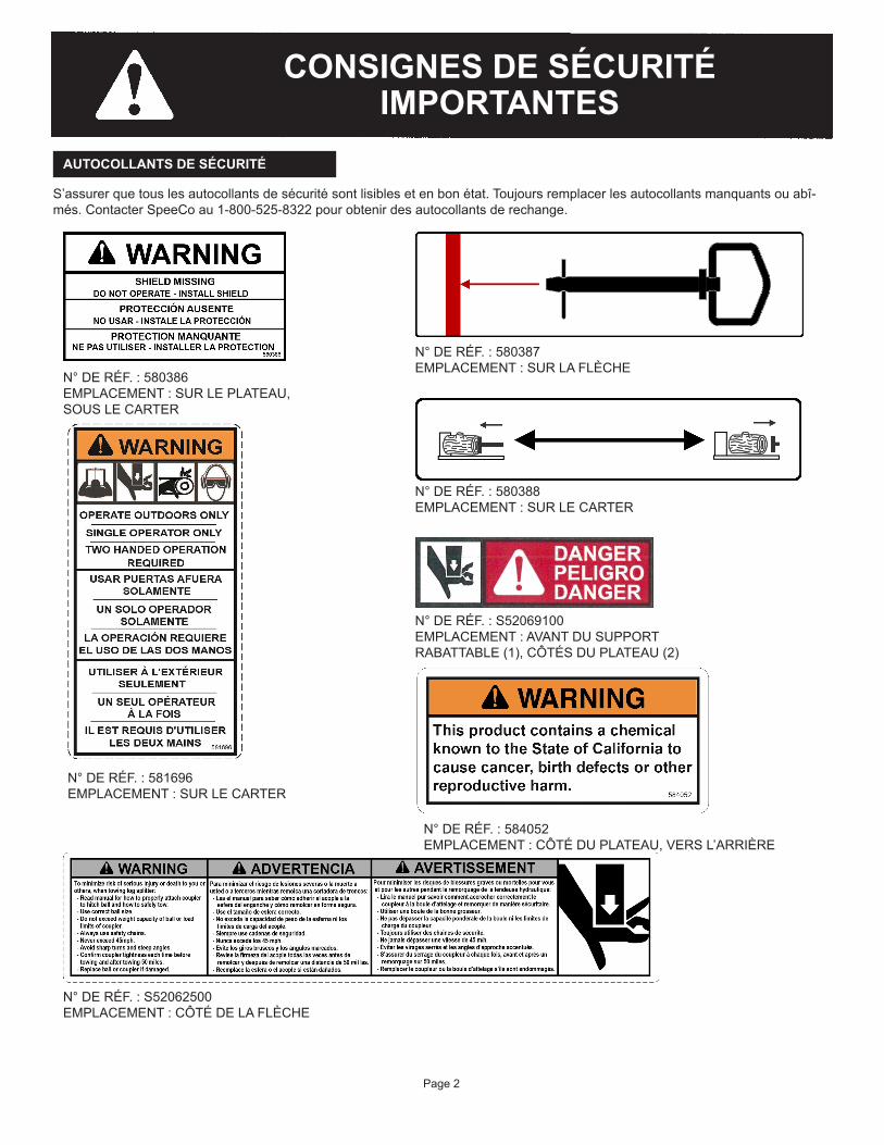
N°DERÉF.:580386EMPLACEMENT : SUR LE PLATEAU, SOUS LE CARTER
AUTOCOLLANTS DE SÉCURITÉ
S’assurerquetouslesautocollantsdesécuritésontlisiblesetenbonétat.Toujoursremplacerlesautocollantsmanquantsouabî-més.ContacterSpeeCoau1-800-525-8322pourobtenirdesautocollantsderechange.
N°DERÉF.:580388EMPLACEMENT : SUR LE CARTER
N°DERÉF.:580387EMPLACEMENT : SUR LA FLÈCHE
N°DERÉF.:581696EMPLACEMENT : SUR LE CARTER
N°DERÉF.:S52062500EMPLACEMENT : CÔTÉ DE LA FLÈCHE
N°DERÉF.:S52069100EMPLACEMENT : AVANT DU SUPPORT RABATTABLE (1), CÔTÉS DU PLATEAU (2)
Page 2
N°DERÉF.:584052EMPLACEMENT : CÔTÉ DU PLATEAU, VERS L’ARRIÈRE
CONSIGNES DE SÉCURITÉ IMPORTANTES

SÉCURITÉ GÉNÉRALE
• TOUJOURSgarderlemanueld’utilisationàproximitépourréférence.Relirelemanuelrégulièrement.• TOUJOURSdélimiterunezonedesécuritémaintenantlesindividusàproximitéàaumoins10ftdelafendeusedebûcheslors
desonutilisation.• TOUJOURSs’assurerquetouslesopérateursontreçuuneformationadéquateetontluetcomprislemanueld’utilisation.• TOUJOURSutiliserlafendeusedebûchesavecunespritclair,libredetouteinfluencedel’alcool,dedroguesoudemédicaments.• TOUJOURSporterdesvêtementsajustés,sanscordons,chaînesoubijouxsusceptiblesdeseprendredansdespièces.• TOUJOURSmaintenirlesvêtementsetcheveuxàl’écartdespiècesmobiles.• TOUJOURSmaintenirlescartersdeprotectionenplaceencoursd’utilisation.• NE JAMAISdéplacermanuellementlafendeusesurunepente.
PRÉPARATION DES BÛCHES
Couperlesdeuxextrémitésdelabûcheaussidroitquepossiblepouréviterquelabûchenesedélogedelafendeuseencoursdefonctionnement.Nepasfendredesbûchesdeplusde24in.delong.
ZONE DE TRAVAIL
• TOUJOURSutilisercettefendeusedebûchessurunterrainstableetplat.• TOUJOURSporterdeschaussuresappropriéesavecuneadhérenceadéquate.• TOUJOURSutiliserlafendeusedebûchesdansunezonedégagée.(Lesgazd’échappementcontiennentdumonoxydede
carbonequipeuts’avérerfatalencasd’inhalation.)• TOUJOURSutiliserlafendeusedebûchessurunterrainplat.(Surunterrainenpente,lafendeuserisquedebasculeroules
bûchesdetomber.)• TOUJOURScalercorrectementlesrouespourévitertoutmouvementdelafendeusedebûchesencoursd’utilisation.• TOUJOURSutiliserlafendeusedebûchesàlalumièredujourouavecunbonéclairage.• TOUJOURSmaintenirlazonedetravailpropre.Retirerimmédiatementleboisfenduautourdelafendeusedebûchespourne
pas trébucherdessus.
UTILISATION DE LA FENDEUSE DE BÛCHES
Lafendeusedebûchesestconçuepourunseulopérateur,setenantdans les « zones de l’opérateur » et qui actionne le loquet de sécurité avec la main la plus proche de la bûche et appuie sur le levier de commandedel’autremain.Seplacerailleurspourutiliserlafendeusepeutentraînerdesblessuresgraves,voiremortelles.
• TOUJOURSchargerlabûchesurleplateaucontrelecoindefendage.• TOUJOURSfaireattentionlorsquel’ondéplaceousoulèvelafendeusedebûches.Sefaireaidersil’unitéesttroplourdepour
êtredéplacéeàunepersonne.• TOUJOURScalercorrectementlesrouespourévitertoutmouvementdelafendeusedebûchesencoursd’utilisation.• NE JAMAISplacerlesmains,despartiesducorpsoudesvêtementssouslescartersencoursd’utilisation.Ilspourraientêtre
prisdanslespiècesmobiles.• SAVOIRcommentarrêterlafendeusedebûchesetdésengagerlescommandesavanttouteutilisation.• NE JAMAIS mettre les mains ou les pieds entre la bûche et le coin de fendage pendant la course avant ou arrière, cela peut
entraînerdesblessuresgraves,voiremortelles.• NE JAMAISenjamberoupasserau-dessusdelafendeusedebûchesencoursd’utilisation.• NE JAMAISsepencheroutendrelebrasau-dessusdelafendeusedebûchespourprendreunebûche.• NE JAMAISessayerdefendredeuxbûchesposéesl’unesurl’autre.• NE JAMAISessayerdefendreunebûchesursalargeur.• NE JAMAISessayerdechargerlafendeusedebûchesquandlepoussoiroulecoindefendageestenmouvement.• NE JAMAISactionnerlescommandesaveclepied,unecordeouundispositifàrallonge.Utiliseruniquementlesdeuxmains.• NE JAMAISdéplacerlafendeusedebûcheslorsquelemoteurtourne.• TOUJOURScouperlemoteur,mêmelorsqu’onlaisselafendeusedebûchessanssurveillancepourunecourtepériode.• NE JAMAIStoucherlesilencieuxetlesautreszoneschaudesdumoteurencoursd’utilisation.Attendrequelemoteurrefroidisse.• TOUJOURS s’assurer que le moteur est arrêté lors du nettoyage régulier des débris de la fendeuse, de la zone de travail et du
moteur.• TOUJOURSs’assurerquelepiedestfixéenpositionabaissée.• TOUJOURSs’assurerquelaflècheestcomplètementrétractéeavantdefendredubois.• Ne JAMAISutilisercettefendeusedebûchesàd’autresfinsquecelledefendredubois.
Page 3
Lenon-respectdecesconsignespeutentraînerdesblessuresoulamort.
K1602
ZONE DE L’OPÉRATEUR
CONSIGNES DE SÉCURITÉ IMPORTANTES

• NE JAMAISutiliserlafendeusedebûchessielleestenmauvaisétatmécaniqueoudoitêtreréparée.• NE JAMAISmodifierlafendeusedebûchesdequelquefaçonquecesoit.Cesmodificationspeuventrendrelafendeusede
bûchesdangereuseetannulentlagarantie.• NE JAMAISmodifierlemoteurpourlefairetourneràdesrégimesexcessifs.Lerégimemoteurmaximumestprérégléparle
fabricantselonleslimitesdesécurité.Voirlemanueld’utilisationdumoteur.Toutemodificationduréglagederégimeannulelagarantiedufabricant.
• TOUJOURSsuivretouteslesprocéduresd’entretienrecommandéesavantd’utiliserlafendeusedebûches.• TOUJOURSremplacerimmédiatementtouteslespiècesendommagéesouusées.• TOUJOURSdébrancherlefildebougieavantdeprocéderàunentretienoudesréparationssurlafendeusedebûches.• TOUJOURSvérifierleniveaud’huilemoteuravanttouteutilisation.• TOUTESlespiècesderechangedoiventêtreconformesauxcaractéristiquestechniquesdufabricant.• À INTERVALLES RÉGULIERS,appliquerunefinecouchedegraissesurledessusdelacrémaillère.• À INTERVALLES RÉGULIERS,nettoyertousleséclatsetdébrisdeboisdesdentsdelacrémaillèreetréappliquerdelagraisse.• À CHAQUE SAISON,lubrifierlesroulementsdepignon.• À INTERVALLES RÉGULIERS,vérifierquetouslesécrous,boulonsetvissontbienserrésavanttouteutilisation.• TOUJOURSvérifierl’étatetlatensiondescourroiesd’entraînementavanttouteutilisation.• À INTERVALLES RÉGULIERS,nettoyeretappliquerunefinecouched’huilesurledessusduplateau.• TOUJOURS tremper la bague d’embrayage en bronze dans de l’huile légère au début de chaque saison et toutes les 100 heures
d’utilisation.• À PLUSIEURSreprisesaucoursdelasaisondefendage,vérifierqueleroulementdecrémaillèreestpropreettournelibrement.
Si ce n’est pas le cas, nettoyer le roulement et le boulon de support et injecter de la graisse dans le boulon de support jusqu’à ce queleroulementtournelibrement.
• TOUJOURSvérifiertouteslesréglementationslocalesetnationalesrelativesauremorquage,àl’immatriculationetàl’éclairageavantderemorquerlafendeusedebûches.
• TOUJOURS s’assurer, avant le remorquage, que la fendeuse de bûches est correctement et solidement attachée au véhicule deremorquageetqueleschaînesdesécuritésontfixéesàl’attelageouaupare-chocsduvéhiculeavecsuffisammentdemoupourpouvoirtourner.Toujoursutiliseruneboulede2in.declasseIaveccettefendeusedebûches.
• TOUJOURSvérifierlafixationdel’attelageavantchaqueremorquageetaprèsunremorquagesur50miles.• TOUJOURSdétacherlafendeusedebûchesduvéhiculederemorquageavantdel’utiliser.• TOUJOURSfaireattentionlorsquel’onreculeaveclafendeusedebûchesremorquée.Ellepeutsemettreenportefeuille.• TOUJOURSprévoirunedistancesupérieureàlalongueurdelafendeusepourprendredesvirages,segarer,traverseraux
intersectionsetdanstouteslessituationsdeconduite.• TOUJOURS mettre la vanne d’arrêt de carburant du moteur en position « OFF » (arrêt) avant de remorquer la fendeuse de
bûches.Lenon-respectdecetteconsignerisquedenoyerlemoteur.• TOUJOURSutiliserdeschaînesdesécuritélorsduremorquagedelafendeusedebûches.• TOUJOURSremplacerlabouleoul’attelages’ilssontendommagésoutropusés.• NE JAMAISremorquerlafendeusedebûchesàplusde45mph.Leremorquagedelafendeusedebûchesàdesvitesses
supérieuresà45mphpeutentraînerunepertedecontrôle,endommagerl’équipementouprovoquerdesblessuresgraves,voiremortelles.Adapterlavitessederemorquageauterrainetauxconditions.
• TOUJOURSredoublerdeprudencelorsduremorquagesurterrainaccidenté,particulièrementsurdespassagesàniveau.• NE JAMAIStransporterdechargeoudeboissurlafendeusedebûches.• NE JAMAISlaisserquelqu’uns’asseoiroumontersurlafendeusedebûches.• NE JAMAISdépasserlacapacitédepoidsdelabouleouleslimitesdechargedel’attelage.• TOUJOURSétendrecomplètementlaflècheetlaverrouillercorrectementpourleremorquage.• TOUJOURSvérifierl’étatetlapressiondegonflagedespneus.Nepasremorquerl’unitésilespneussontusés,endommagés
oumalgonflés.• TOUJOURSs’assurerquelepiedestfixéenpositionrelevéeavanttoutremorquage.
ENTRETIEN GÉNÉRAL
SÉCURITÉ DE L’ENVIRONNEMENT DE TRAVAIL
SÉCURITÉ DU REMORQUAGE
• NE JAMAISutiliserlafendeusedebûchesàproximitéd’uneflammeoud’uneétincelle.• NE JAMAISremplirleréservoirdecarburantlorsquelemoteurestchaudoutourne.• TOUJOURS couper le moteur et lelaisserrefroidiravantdefairel’appointdecarburant.• NE JAMAISfumerpendantl’utilisationdelafendeusedebûchesoul’appointdecarburant.Lesémanationsdecarburant
peuventfacilementexploser.• NE JAMAISremiserdecarburantàl’intérieurd’unemaisonouprèsd’unappareildechauffage.• Faire l’appoint de la fendeuse de bûches UNIQUEMENTdansunezonedégagée,exempted’émanationsoudedéversements
decarburant.• TOUJOURSremettrelebouchondecarburantfermementenplace.Encasdedéversementdecarburant,écarterlafendeusedebûches
delazonedudéversementetévitertoutesourced’inflammationjusqu’àcequelecarburantdéverséaitétécorrectementnettoyé.• Par mesure de précaution contre un éventuel incendie, TOUJOURSavoirunextincteurdeclasseBàportéedemainlorsde
l’utilisationdecettefendeusedebûchesdansdesendroitssecs.• TOUJOURSviderleréservoirdecarburantavantunremisagepourévitertoutrisqued’incendie.• TOUJOURSremiserlecarburantcorrectementdansunrécipientapprouvé.• NE JAMAISlaisserdecopeauxoudébrisdeboiss’accumulersurlemoteur.REMARQUE IMPORTANTE – (pare-étincelles) :Parmesuredeprécautioncontred’éventuellesétincelles,toujoursavoirunextincteurdeclasseBàportéedemainlorsdel’utilisationdecettefendeusedebûchesdansdesendroitssecs.Cettefendeusedebûchesestéquipéed’unmoteuràcombustioninterne et ne peut être utilisée sur ou près d’un terrain non entretenu, recouvert d’arbres, de broussailles ou d’herbe, que si le système d’échappement du moteur comprend un pare-étincelles conforme à la réglementation locale ou nationale en vigueur (le cas échéant).Siunpare-étincellesestutilisé,l’opérateuresttenudelemaintenirdansunétatdefonctionnementefficace.Dansl’ÉtatdeCalifornie,unpare-étincellesestexigéparlaloi.D’autresÉtatspeuventappliquerdesloissimilaires.Lesloisfédéraless’appliquentsurlesterritoiresfédéraux.Unpare-étincellesestdisponibleenoptionauprèsduconcessionnairedemoteursleplusproche.Toujoursvérifierlesexigenceslégalesenlamatièredanslarégiond’utilisation.
Page 4
CONSIGNES DE SÉCURITÉ IMPORTANTES

ÉLÉMENT Nº RÉF. DESCRIPTION QTÉ
1 578727 ESSIEU, FENDEUSE CINÉTIQUE 12 581740 PLAQUE DE POUSSÉE NOIRE DU PLATEAU, FENDEUSE CINÉTIQUE 13 581492 PIED, FENDEUSE CINÉTIQUE 14 S400312B0 PNEU DE FENDEUSE AVEC JOINT D’ÉTANCHÉITÉ DE ROULEMENT 25 578705 FLÈCHE, FENDEUSE CINÉTIQUE 16 580851 TABLESPEECOROUGE,FENDEUSECINÉTIQUE,SOUD. 17 575856 COURROIE, GATES, A74 28 581493 PROTECTEUR DE COURROIES, AVEC AUTOCOLLANT, FENDEUSE CINÉTIQUE 19 581695 CARTER SPEECO GAUCHE, AVEC AUTOCOLLANT, FENDEUSE CINÉTIQUE 110 581555 CARTER SPEECO DROIT, AVEC AUTOCOLLANT, FENDEUSE CINÉTIQUE 111 578723 LEVIER SUPÉRIEUR NOIR, FENDEUSE CINÉTIQUE 1
INSTRUCTIONS DE MONTAGE
REMARQUE:Déballerlapaletteetenvérifiersoigneusementlecontenuavantdecommencerlemontage.
Page 5
K1603
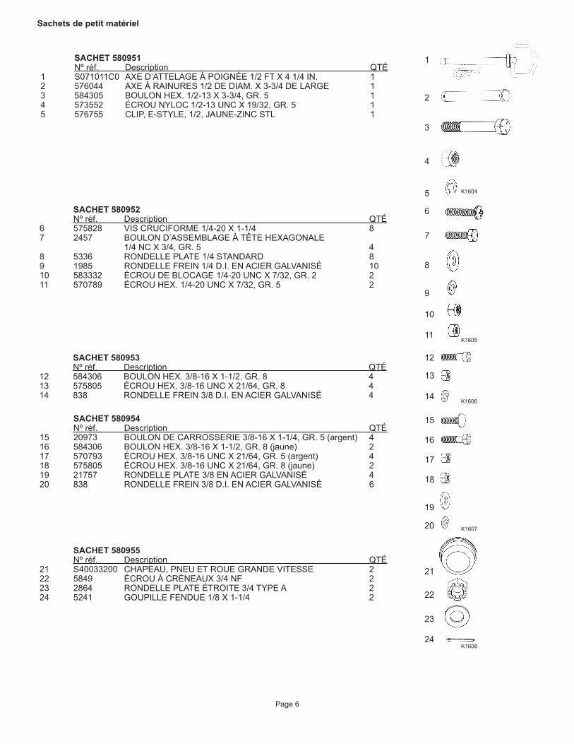
SACHET 580953 Nºréf. Description QTÉ12 584306 BOULONHEX.3/8-16X1-1/2,GR.8 413 575805 ÉCROUHEX.3/8-16UNCX21/64,GR.8 414 838 RONDELLEFREIN3/8D.I.ENACIERGALVANISÉ 4
Sachets de petit matériel
SACHET 580951 Nºréf. Description QTÉ1 S071011C0 AXED’ATTELAGEÀPOIGNÉE1/2FTX41/4IN. 12 576044 AXEÀRAINURES1/2DEDIAM.X3-3/4DELARGE 13 584305 BOULONHEX.1/2-13X3-3/4,GR.5 14 573552 ÉCROUNYLOC1/2-13UNCX19/32,GR.5 15 576755 CLIP, E-STYLE, 1/2, JAUNE-ZINC STL 1
1
2
3
4
5
6
7
8
9
10
11
12
13
14
15
16
17
18
19
20
21
22
23
24
SACHET 580952 Nºréf. Description QTÉ6 575828 VIS CRUCIFORME 1/4-20 X 1-1/4 87 2457 BOULON D’ASSEMBLAGE À TÊTE HEXAGONALE 1/4NCX3/4,GR.5 48 5336 RONDELLE PLATE 1/4 STANDARD 89 1985 RONDELLEFREIN1/4D.I.ENACIERGALVANISÉ 1010 583332 ÉCROUDEBLOCAGE1/4-20UNCX7/32,GR.2 211 570789 ÉCROUHEX.1/4-20UNCX7/32,GR.5 2
SACHET 580954 Nºréf. Description QTÉ15 20973 BOULONDECARROSSERIE3/8-16X1-1/4,GR.5(argent) 416 584306 BOULONHEX.3/8-16X1-1/2,GR.8(jaune) 217 570793 ÉCROUHEX.3/8-16UNCX21/64,GR.5(argent) 418 575805 ÉCROUHEX.3/8-16UNCX21/64,GR.8(jaune) 219 21757 RONDELLE PLATE 3/8 EN ACIER GALVANISÉ 420 838 RONDELLEFREIN3/8D.I.ENACIERGALVANISÉ 6
SACHET 580955 Nºréf. Description QTÉ21 S40033200 CHAPEAU, PNEU ET ROUE GRANDE VITESSE 222 5849 ÉCROU À CRÉNEAUX 3/4 NF 223 2864 RONDELLE PLATE ÉTROITE 3/4 TYPE A 224 5241 GOUPILLE FENDUE 1/8 X 1-1/4 2
Page 6
K1605
K1606
K1607
K1608
K1604

MONTAGE
Page 7
Remarque : La palette est utilisée pour l’alignement lors du montage. NE PAS DÉTRUIRE NI METTRE AU REBUT. S’assurer que les côtés de la palette n’ont pas été endommagés.
ÉLÉMENT NºRÉF. DESCRIPTION QTÉ1 S400312B0 PNEU 22 SAC 580955 RONDELLE PLATE 3/4 23 SAC580955 ÉCROUHEX.3/4IN-16SL-NF 24 SAC 580955 GOUPILLE FENDUE 1/8 X 1-1/4 25 SAC 580955 CAPUCHON ANTIPOUSSIÈRE 2
ÉTAPE 3 :Replacerl’ensembleessieudanslapalette,lesrouesétantemboîtéesentrelesdeuxlattesenboislesplusaucentre.Placerlacourtesectionenboisdesoutiendumoteursouslesupportdumoteurpourmaintenirl’ensembleessieudanslapositionvoulue.S’assurerquelescôtésdelapaletten’ontpasétéendommagés.
BLOC DE SUPPORT
K1649
K1652
ÉTAPE 1 :Poserlapalettesurunsolplatdansunespacedégagépourlemontage.Retirerledessusdelapaletteetlemettredecôté.Enlevertouslesobjetsdelapalette.Localiserlessacsdeboulonnerie580955et580953danslaboîtedeboulonnerie.ÉTAPE 2 :Retirerlesrouesdeleuremballaged’expédition.Retirerlescapotsdeprotectionenplastiquebleuetpositionnerlestigesdevalvesversl’extérieur.Monterlesroues(1)surlesessieux,lestigesdevalvesorientéesversl’extérieur.Fixeràl’aidedesrondelles(2)etdesécrousàcréneaux(3).Serrerfermementl’écrouàcréneauxsurl’axedel’essieu.Larouedoitêtredifficileàtourneràlamain;ramenerensuitel’écrouàcréneauxde1/3à1/2tour.Alignerl’écrouàcréneauxavecletroudansl’axedel’essieupuisplierlagoupillefendue.Installerlecapuchonantipoussière.

Page 8
ÉTAPE 4A :Lever la poutre (5) et la positionner en alignant les trous des boulons de l’ensemble essieu (1) avec les trous des boulons de montagedel’ensemblepoutre.Unepartiedelapoutredépasseradelapaletteetserasoutenueparlecôtédelapalette.Installerlesboulons(2),lesrondellesdeblocage(3)etlesécrous(4).Serrerfermementlesquatreboulons.
ÉTAPE 4B :Installerlepiedpivotant(1)enpositionbasse.Installerlagoupille(3)aveclabaguedeblocage(4)autraversdutrousupérieur.Installerlagoupilleàressort(2)autraversdestrousinférieursdanslapoutreetlepiedpivotantàbéquille.InstallerleclipenRpourfixerlagoupille.
ÉLÉMENT NºRÉF. DESCRIPTION QTÉ1 578727 ENSEMBLE ESSIEU 12 SAC580953 BOULONHEX.3/8IN-16X1-1/2INCALIBRE8 43 SAC580953 RONDELLEDEBLOCAGEACIERGALVANISÉD.I.3/8 44 SAC580953 ÉCROUHEX.3/8-16UNCX21/64,CALIBRE8 45 581740 ENSEMBLE POUTRE 1
ÉLÉMENT NºRÉF. DESCRIPTION QTÉ1 581492 PIED 12 SAC 580951 GOUPILLE À RESSORT 1/2 FT X 4 1/4 IN 13 SAC 580951 GOUPILLE CANNELÉE 1/2 DIA 3-3/4 LG 14 SAC 580951 CLIP, E-STYLE, 1/2, JAUNE-ZINC STL 1
ÉTAPE 4C :Souleversuffisammentl’ensembleessieu/poutre,afinquelapalettepuisseêtreretiréeetmiseaurebut.Abaisserlafendeuseausolpourlemontagefinal.
K1650
K1651
K1653
K1654

ÉTAPE 5A :Localiserlesboulonsdemontagedumoteuretécrousdetension.
Page 9
ÉCROU DE TENSION BOULON DE MONTAGE DU MOTEUR
ÉTAPE 5B :Desserrer très légèrement les boulons de montage du moteur et écrous de tension pour pouvoir ajuster la position du moteurenlefaisantglissersanslefairebasculer.S’assurerquelemoteurresteperpendiculaireetalignéparrapportauvolantpendantleréglagedetensiondescourroies.
ÉTAPE 5C :Positionnerlesdeuxcourroiestrapézoïdales(5)surlevolant.Installerlescourroiesdanslesgorgestrapézoïdalesdelapoulied’embrayage,encommençantparlaplusprochedumoteur.
ÉTAPE 5D :Pourréglerlatensiondescourroies,utiliserlajaugefourniequidéfinitlatensiondescourroiesà60lbs.Tirersurlacourroieàl’aideducôtécrochetdelajauge,commeillustréci-dessous,àenvironmi-cheminentrelevolantetlapoulied’embrayagesurlalongueurdelacourroie.
CÔTÉ POIGNÉE
CÔTÉ CROCHET
POULIE D’EMBRAYAGE
VOLANT
K1613
K1614 K1615
K1616
K1617

Page 10
Si les encoches de la poignée sont au-dessus du bord, la courroie est trop tendueetlatensiondoitêtreréduite.Rapprocher le moteur des roues pour réduire latension.
Si les encoches de la poignée sont en dessous du bord, la courroie n’est pas assez tendue et la tension doit être augmentée.Éloignerlemoteurdesrouespouraugmenterlatension.
ÉTAPE 5F :Répétercettemesuresurl’autrecourroie,serrerlesboulonsdemontagedumoteuretvérifierànouveaulatensiondescourroiespours’assurerqu’elleesttoujourscorrecte.UNECOURROIETROPTENDUEENTRAÎNEUNEUSUREETUNEDÉFAILLANCEPRÉMATURÉESDEL’EMBRAYAGEETPEUTCAUSERUNEUSUREDEL’ARBREMOTEUR.
K1618 K1620
K1619
K1622
K1621K1623
K1624
ÉTAPE 5E :Tirerlentementavecunmouvementréguliersurlacourroieàl’aidedelajaugejusqu’àcequelesencochesducôtécrochetsoientalignéessurlasurfacesupérieuredel’autrecourroie,commeillustré.Unefoislecôtécrochetaligné,observerlapartiesupérieuredelajauge.Lorsquelesencochesdelapartiepoignéesontalignéessurlebordillustré,lacourroietiréeestcorrectementtendue.
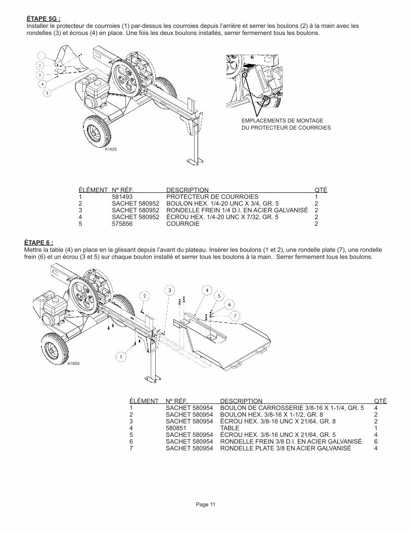
ÉLÉMENT NºRÉF. DESCRIPTION QTÉ1 581493 PROTECTEUR DE COURROIES 12 SACHET580952 BOULONHEX.1/4-20UNCX3/4,GR.5 23 SACHET580952 RONDELLEFREIN1/4D.I.ENACIERGALVANISÉ 24 SACHET580952 ÉCROUHEX.1/4-20UNCX7/32,GR.5 25 575856 COURROIE 2
ÉTAPE 5G :Installer le protecteur de courroies (1) par-dessus les courroies depuis l’arrière et serrer les boulons (2) à la main avec les rondelles(3)etécrous(4)enplace.Unefoislesdeuxboulonsinstallés,serrerfermementtouslesboulons.
Page 11
EMPLACEMENTS DE MONTAGE DU PROTECTEUR DE COURROIES
K1625
ÉTAPE 6 :Mettrelatable(4)enplaceenlaglissantdepuisl’avantduplateau.Insérerlesboulons(1et2),unerondelleplate(7),unerondellefrein(6)etunécrou(3et5)surchaquebouloninstalléetserrertouslesboulonsàlamain.Serrerfermementtouslesboulons.
ÉLÉMENT NºRÉF. DESCRIPTION QTÉ1 SACHET580954 BOULONDECARROSSERIE3/8-16X1-1/4,GR.5 42 SACHET580954 BOULONHEX.3/8-16X1-1/2,GR.8 23 SACHET580954 ÉCROUHEX.3/8-16UNCX21/64,GR.8 24 580851 TABLE 15 SACHET580954 ÉCROUHEX.3/8-16UNCX21/64,GR.5 46 SACHET580954 RONDELLEFREIN3/8D.I.ENACIERGALVANISÉ 67 SACHET 580954 RONDELLE PLATE 3/8 EN ACIER GALVANISÉ 4
K1655

Page 12
ÉTAPE 8 :Lecarterdevolantprincipal(1et2)secomposededeuxmoitiés.Commencerparfairepivoterlesupportsupérieurenpositionverticaleetlefixeraveclesboulons(6)etlesécrousdeblocage(7).Installerlecarterencommençantparlecôtéopposéaumoteur.Fixerlecarteràl’unitéaveclesvis(5),lesrondellesplates(3)etlesrondellesfrein(4).Serrerfermementtoutelaboulonneriefixantlecarter.
ÉLÉMENT NºRÉF. DESCRIPTION QTÉ1 581555 CARTER DROIT 12 581695 CARTER GAUCHE 13 SACHET 580952 RONDELLE PLATE 1/4 EN ACIER GALVANISÉ 84 SACHET580952 RONDELLEFREIN1/4D.I.ENACIERGALVANISÉ 85 SACHET 580952 VIS CRUCIFORME 1/4-20 X 1-1/4 86 SACHET580952 BOULONHEX.1/4-20UNCX1,GR.5 27 SACHET580952 ÉCROUDEBLOCAGE1/4-20UNCX7/32,GR.2 2
K1628
SUPPORT
ÉTAPE 7 :Insérerlaflèche(1)dansl’unitéenlaglissantdepuisl’avant.Insérerleboulon(3)danslaflècheetlefixeravecl’écrounyloc(2).
ÉLÉMENT NºRÉF. DESCRIPTION QTÉ1 578705 FLÈCHE 12 SACHET580951 ÉCROUNYLOC1/2-13UNCX19/32,GR.5 13 SACHET580951 BOULONHEX.1/2-13X3-3/4,GR.5 1
K1626
(Tableenlevépourmontrerlesdétails.)

ÉTAPE 9 :Visserlelevierdecommande(1)enpositionsurledessusdel’unité.Verrouillerfermementlelevierenplaceenserrantl’écroudeblocagesituédessus.
REMARQUES
Page 13
ÉLÉMENT NºRÉF. DESCRIPTION QTÉ1 578723 LEVIER 1
K1629
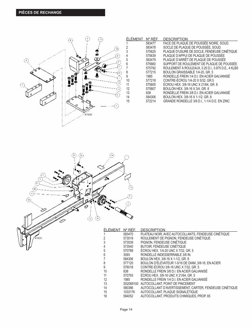
PIÈCES DE RECHANGE
Page 14
K1630
K1631
ÉLÉMENT NºRÉF. DESCRIPTION1 583470 PLATEAU NOIR, AVEC AUTOCOLLANTS, FENDEUSE CINÉTIQUE2 573519 ROULEMENT DE PIGNON, FENDEUSE CINÉTIQUE3 573539 PIGNON, FENDEUSE CINÉTIQUE4 573540 BUTOIR, FENDEUSE CINÉTIQUE5 570789 ÉCROU HEX. 1/4-20 UNC X 7/32, GR. 56 3093 RONDELLE INDESSERRABLE 3/8 IN.7 584306 BOULON HEX. 3/8-16 X 1-1/2, GR. 88 577120 BOULON D’ÉLÉVATEUR 1-5/16 DE DIAM.,3/8-16, EN ACIER9 576018 CONTRE-ÉCROU 3/8-16 UNC X 7/32, GR. 510 838 RONDELLE FREIN 3/8 D.I. EN ACIER GALVANISÉ11 570793 ÉCROU HEX. 3/8-16 UNC X 21/64, GR. 512 1985 RONDELLE FREIN 1/4 D.I. EN ACIER GALVANISÉ13 S52069100 AUTOCOLLANT, POINT DE PINCEMENT14 580386 AUTOCOLLANT D’AVERTISSEMENT, CARTER, FENDEUSE CINÉTIQUE15 1033176 AUTOCOLLANT, PLAQUE SIGNALÉTIQUE 16 584052 AUTOCOLLANT, PRODUITS CHIMIQUES, PROP. 65
ÉLÉMENT NºRÉF. DESCRIPTION1 583477 FACE DE PLAQUE DE POUSSÉE NOIRE, SOUD.2 583478 SOCLE DE PLAQUE DE POUSSÉE, SOUD.3 575625 PLAQUE D’USURE DE SOCLE, FENDEUSE CINÉTIQUE4 575639 PLAQUE D’APPUI DE PLAQUE DE POUSSÉE5 583479 PLAQUE D’ARRÊT DE PLAQUE DE POUSSÉE6 575660 SUPPORT DE ROULEMENT DE PLAQUE DE POUSSÉE7 575792 ROULEMENT À ROULEAUX, 0.25 D.I., 0.875 D.E., 4 KLBS8 577215 BOULON GRAISSABLE 1/4-20, GR. 59 1985 RONDELLE FREIN 1/4 D.I. EN ACIER GALVANISÉ10 577218 CONTRE-ÉCROU 1/4-20 X 5/32, GR.511 575805 ÉCROU HEX. 3/8-16 UNC X 21/64, GR. 812 575807 BOULON HEX. 3/8-16 X 3/4, GR. 813 838 RONDELLE FREIN 3/8 D.I. EN ACIER GALVANISÉ14 584306 BOULON HEX. 3/8-16 X 1-1/2, GR. 815 572214 GRANDE RONDELLE 3/8 D.I., 1-1/4 D.E. EN ZINC

Page 15
ÉLÉMENT NºRÉF. DESCRIPTION1 S40034600 ATTELAGE 2 VOIES DE FENDEUSE2 583486 FLÈCHE, AVEC AUTOCOLLANTS, FENDEUSE CINÉTIQUE3 565286 RONDELLE PLATE M10 EN ACIER GALVANISÉ4 565276 BOULON HEX. M10 X 1.5 X 120, GR. 55 565275 BOULON HEX. M10 X 1.5 X 100, GR. 56 S40032300 CHAÎNE À 20 MAILLONS AVEC CROCHET7 584307 ÉCROU NYLOC M10 X 1.5 X 10, GR. 88 S52062500 AUTOCOLLANT D’AVERTISSEMENT TRILINGUE, FLÈCHE
K1632
K1633
ÉLÉMENT NºRÉF. DESCRIPTION1 583480 BIELLETTE À ARC-BOUTEMENT, FENDEUSE CINÉTIQUE, SOUD.2 575704 ROULEMENT À ROULEAUX 3/8 D.I., 1-1/4. D.E.3 576757 BOULON À ÉPAULEMENT 3/8 X 2-1/2 EN ACIER4 838 RONDELLE FREIN 3/8 D.I. EN ACIER GALVANISÉ5 574435 ÉCROU NYLOC 5/16-18 UNC X 11/32, GR. 5

Page 16
ÉLÉMENT NºRÉF. DESCRIPTION1 583482 LEVIER, FENDEUSE CINÉTIQUE, SOUD.2 576031 RESSORT DE TORSION, LEVIER GAUCHE3 576032 RESSORT DE TORSION, LEVIER DROIT
ÉLÉMENT NºRÉF. DESCRIPTION1 583490 ESSIEU 8 IN., FENDEUSE CINÉTIQUE, SOUD.2 581582 MOTEUR KOHLER SH2653 575523 EMBRAYAGE, FENDEUSE CINÉTIQUE4 S52029800 AUTOCOLLANT, ÉTATS-UNIS5* 583491 JEU DE BOULONNERIE, MOTEUR, FENDEUSE CINÉTIQUE* NON ILLUSTRÉ
K1634
K1635
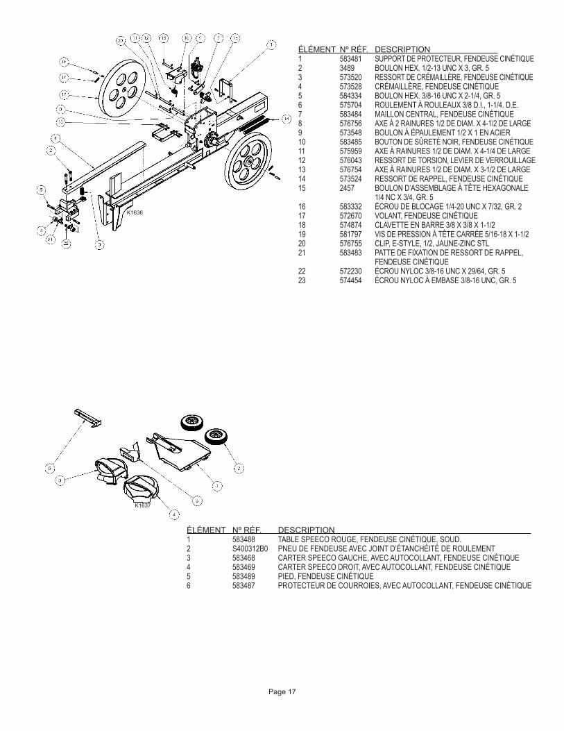
Page 17
ÉLÉMENT NºRÉF. DESCRIPTION 1 583481 SUPPORT DE PROTECTEUR, FENDEUSE CINÉTIQUE2 3489 BOULON HEX. 1/2-13 UNC X 3, GR. 53 573520 RESSORT DE CRÉMAILLÈRE, FENDEUSE CINÉTIQUE4 573528 CRÉMAILLÈRE, FENDEUSE CINÉTIQUE5 584334 BOULON HEX. 3/8-16 UNC X 2-1/4, GR. 56 575704 ROULEMENT À ROULEAUX 3/8 D.I., 1-1/4. D.E.7 583484 MAILLON CENTRAL, FENDEUSE CINÉTIQUE8 576756 AXE À 2 RAINURES 1/2 DE DIAM. X 4-1/2 DE LARGE9 573548 BOULON À ÉPAULEMENT 1/2 X 1 EN ACIER10 583485 BOUTON DE SÛRETÉ NOIR, FENDEUSE CINÉTIQUE11 575959 AXE À RAINURES 1/2 DE DIAM. X 4-1/4 DE LARGE12 576043 RESSORT DE TORSION, LEVIER DE VERROUILLAGE13 576754 AXE À RAINURES 1/2 DE DIAM. X 3-1/2 DE LARGE14 573524 RESSORT DE RAPPEL, FENDEUSE CINÉTIQUE15 2457 BOULON D’ASSEMBLAGE À TÊTE HEXAGONALE
1/4 NC X 3/4, GR. 516 583332 ÉCROU DE BLOCAGE 1/4-20 UNC X 7/32, GR. 217 572670 VOLANT, FENDEUSE CINÉTIQUE18 574874 CLAVETTE EN BARRE 3/8 X 3/8 X 1-1/219 581797 VIS DE PRESSION À TÊTE CARRÉE 5/16-18 X 1-1/220 576755 CLIP, E-STYLE, 1/2, JAUNE-ZINC STL21 583483 PATTE DE FIXATION DE RESSORT DE RAPPEL,
FENDEUSE CINÉTIQUE22 572230 ÉCROU NYLOC 3/8-16 UNC X 29/64, GR. 523 574454 ÉCROU NYLOC À EMBASE 3/8-16 UNC, GR. 5
ÉLÉMENT NºRÉF. DESCRIPTION1 583488 TABLE SPEECO ROUGE, FENDEUSE CINÉTIQUE, SOUD.2 S400312B0 PNEU DE FENDEUSE AVEC JOINT D’ÉTANCHÉITÉ DE ROULEMENT3 583468 CARTER SPEECO GAUCHE, AVEC AUTOCOLLANT, FENDEUSE CINÉTIQUE4 583469 CARTER SPEECO DROIT, AVEC AUTOCOLLANT, FENDEUSE CINÉTIQUE5 583489 PIED, FENDEUSE CINÉTIQUE6 583487 PROTECTEUR DE COURROIES, AVEC AUTOCOLLANT, FENDEUSE CINÉTIQUE
K1636
K1637
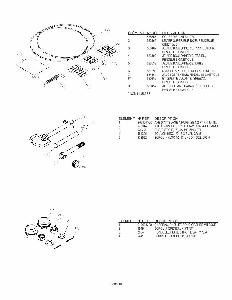
Page 18
ÉLÉMENT NºRÉF. DESCRIPTION1 575856 COURROIE, GATES, A742 583466 LEVIER SUPÉRIEUR NOIR, FENDEUSE
CINÉTIQUE3 583467 JEU DE BOULONNERIE, PROTECTEUR,
FENDEUSE CINÉTIQUE4 583492 JEU DE BOULONNERIE, ESSIEU,
FENDEUSE CINÉTIQUE5 583539 JEU DE BOULONNERIE, TABLE,
FENDEUSE CINÉTIQUE6 581299 MANUEL, SPEECO, FENDEUSE CINÉTIQUE7 584561 JAUGE DE TENSION, FENDEUSE CINÉTIQUE8* 580382 ÉTIQUETTE VOLANTE, SPEECO,
FENDEUSE CINÉTIQUE9* 580457 AUTOCOLLANT, CARACTÉRISTIQUES,
FENDEUSE CINÉTIQUE* NON ILLUSTRÉ
ÉLÉMENT NºRÉF. DESCRIPTION1 S071011C0 AXE D’ATTELAGE À POIGNÉE 1/2 FT X 4 1/4 IN.2 576044 AXE À RAINURES 1/2 DE DIAM. X 3-3/4 DE LARGE3 576755 CLIP, E-STYLE, 1/2, JAUNE-ZINC STL4 584305 BOULON HEX. 1/2-13 X 3-3/4, GR. 55 573552 ÉCROU NYLOC 1/2-13 UNC X 19/32, GR. 5
ÉLÉMENT NºRÉF. DESCRIPTION1 S40033200 CHAPEAU, PNEU ET ROUE GRANDE VITESSE2 5849 ÉCROU À CRÉNEAUX 3/4 NF3 2864 RONDELLE PLATE ÉTROITE 3/4 TYPE A4 5241 GOUPILLE FENDUE 1/8 X 1-1/4
K1638
K1640
K1639

Page 19
ÉLÉMENT NºRÉF. DESCRIPTION1 S52069100 AUTOCOLLANT, POINT DE PINCEMENT
ÉLÉMENT NºRÉF. DESCRIPTION1 581696 AUTOCOLLANT, LEVIER DE
VERROUILLAGE, FENDEUSE CINÉTIQUE2 580388 AUTOCOLLANT, LEVIER, FENDEUSE
CINÉTIQUE
REMARQUE:Vérifierlebonfonctionnementdelamachineaprèstoutremplacementdepièce.
K1641
K1642

AVERTISSEMENT : NE PAS PLACER LES MAINS SOUS LE CARTER LORSQUE LE MOTEUR TOURNE. ATTENDRE AU MOINS TRENTE (30) SECONDES QUE LE VOLANT S’IMMOBILISE APRÈS L’ARRÊT DU MOTEUR POUR EFFECTUER TOUT RÉGLAGE.
INSTRUCTIONS D’UTILISATION
AVERTISSEMENT : LORSQUE LE MOTEUR TOURNE, NE PLACER À AUCUN MOMENT LES MAINS ENTRE LA BÛCHE, LE COIN DE FENDAGE ET LE POUSSOIR. TOUJOURS TENIR LES MAINS À L’ÉCART DES PIÈCES MOBILES.
AVERTISSEMENT : NE JAMAIS ESSAYER DE FENDRE UNE BÛCHE SUR SA LARGEUR.
Page 20
AVERTISSEMENT : Lire et bien comprendre toutes les instructions de ce manuel et des autocollants de sécurité avant de monter ou d’utiliser cette fendeuse de bûches. Le non-respect de ces consignes peut entraîner des blessures graves, voire mortelles. Ne laisser personne n’ayant pas lu ce manuel utiliser cette fendeuse de bûches. Comme tout équipement électrique, une fendeuse de bûches peut s’avérer dangereuse si elle n’est pas montée ou utilisée correctement. Ne pas utiliser cette fendeuse si l’on a des questions quant à son utilisation en toute sécurité. Pour obtenir des réponses à ses questions, contacter notre service d’assistance technique au 1-800-525-8322.
K1643
K1644
REMARQUE : Installerlafendeusedebûchesdansunezoneplaneetdégagéeetcalerlesroues.REMARQUE : Vérifiertouslesniveauxdeliquidesetfairel’appointaveclesliquidesappropriés,sinécessaire,avantdedémarrer
lemoteur.REMARQUE : Démarrerlemoteurconformémentauxconsignesd’utilisationdufabricantdumoteurcorrespondantautypedu
moteuretlaisserlemoteuratteindresonpleinrégimeavantd’utiliserl’unité.REMARQUE : Lorsquelafendeusen’estpasutilisée,fermerlavannedecarburantconformémentaumanueldufabricantdumoteur.REMARQUE : Tremper la bague d’embrayage en bronze dans de l’huile légère au début de chaque saison et toutes les
100heuresd’utilisation.
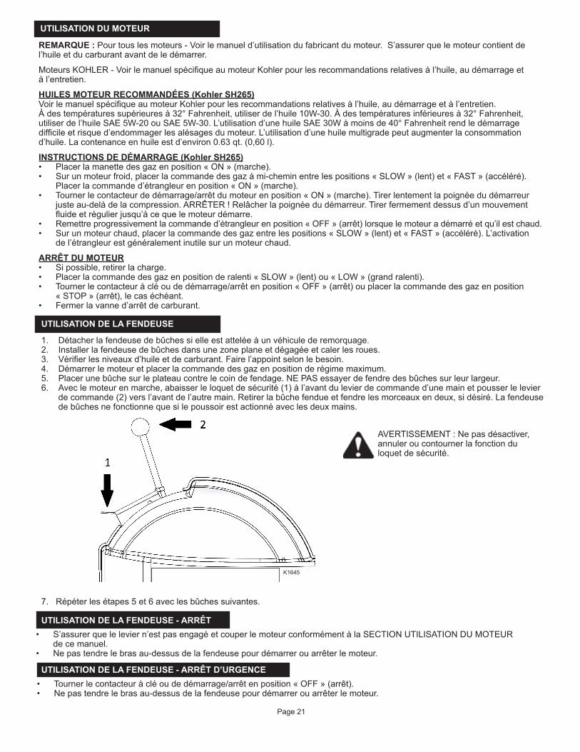
REMARQUE : Pour tous les moteurs - Voir le manueld’utilisationdufabricantdumoteur.S’assurer que le moteur contient de l’huileetducarburantavantdeledémarrer.
MoteursKOHLER-VoirlemanuelspécifiqueaumoteurKohlerpourlesrecommandationsrelativesàl’huile,audémarrageetàl’entretien.
HUILES MOTEUR RECOMMANDÉES (Kohler SH265)VoirlemanuelspécifiqueaumoteurKohlerpourlesrecommandationsrelativesàl’huile,audémarrageetàl’entretien.Àdestempératuressupérieuresà32°Fahrenheit,utiliserdel’huile10W-30.Àdestempératuresinférieuresà32°Fahrenheit,utiliserdel’huileSAE5W-20ouSAE5W-30.L’utilisationd’unehuileSAE30Wàmoinsde40°Fahrenheitrendledémarragedifficileetrisqued’endommagerlesalésagesdumoteur.L’utilisationd’unehuilemultigradepeutaugmenterlaconsommationd’huile.Lacontenanceenhuileestd’environ0.63qt.(0,60l).
INSTRUCTIONS DE DÉMARRAGE (Kohler SH265)• Placerlamanettedesgazenposition«ON»(marche).• Surunmoteurfroid,placerlacommandedesgazàmi-cheminentrelespositions«SLOW»(lent)et«FAST»(accéléré).
Placerlacommanded’étrangleurenposition«ON»(marche).• Tournerlecontacteurdedémarrage/arrêtdumoteurenposition«ON»(marche).Tirerlentementlapoignéedudémarreur
justeau-delàdelacompression.ARRÊTER!Relâcherlapoignéedudémarreur.Tirerfermementdessusd’unmouvementfluideetrégulierjusqu’àcequelemoteurdémarre.
• Remettreprogressivementlacommanded’étrangleurenposition«OFF»(arrêt)lorsquelemoteuradémarréetqu’ilestchaud.• Surunmoteurchaud,placerlacommandedesgazentrelespositions«SLOW»(lent)et«FAST»(accéléré).L’activation
del’étrangleurestgénéralementinutilesurunmoteurchaud.
ARRÊT DU MOTEUR• Sipossible,retirerlacharge.• Placerlacommandedesgazenpositionderalenti«SLOW»(lent)ou«LOW»(grandralenti).• Tourner le contacteur à clé ou de démarrage/arrêt en position « OFF » (arrêt) ou placer la commande des gaz en position
«STOP»(arrêt),lecaséchéant.• Fermerlavanned’arrêtdecarburant.
UTILISATION DU MOTEUR
UTILISATION DE LA FENDEUSE
1. Détacherlafendeusedebûchessielleestatteléeàunvéhiculederemorquage.2. Installerlafendeusedebûchesdansunezoneplaneetdégagéeetcalerlesroues.3. Vérifierlesniveauxd’huileetdecarburant.Fairel’appointselonlebesoin.4. Démarrerlemoteuretplacerlacommandedesgazenpositionderégimemaximum.5. Placerunebûchesurleplateaucontrelecoindefendage.NEPASessayerdefendredesbûchessurleurlargeur.6. Avec le moteur en marche, abaisser le loquet de sécurité (1) à l’avant du levier de commande d’une main et pousser le levier
decommande(2)versl’avantdel’autremain.Retirerlabûchefendueetfendrelesmorceauxendeux,sidésiré.Lafendeusedebûchesnefonctionnequesilepoussoirestactionnéaveclesdeuxmains.
7.Répéterlesétapes5et6aveclesbûchessuivantes.
UTILISATION DE LA FENDEUSE - ARRÊT• S’assurer que le levier n’est pas engagé et couper le moteur conformément à la SECTION UTILISATION DU MOTEUR
decemanuel.• Nepastendrelebrasau-dessusdelafendeusepourdémarrerouarrêterlemoteur.
Page 21
UTILISATION DE LA FENDEUSE - ARRÊT D’URGENCE• Tournerlecontacteuràcléoudedémarrage/arrêtenposition«OFF»(arrêt).• Nepastendrelebrasau-dessusdelafendeusepourdémarrerouarrêterlemoteur.
AVERTISSEMENT : Ne pas désactiver, annuler ou contourner la fonction du loquetdesécurité.
K1645

REMORQUAGE
POSITIONS DE LA FLÈCHE - REMORQUAGE ET UTILISATIONPositiondelaflèche–ÉTENDUE–Remorquage
Pour le remorquage :
• Étendrelaflèche.• Retirerlagoupilledesécuritéetl’axemaintenantlesupportenpositionabaissée.• Releverlepiedetlefixeraveclagoupilledesécuritéetl’axe.
Positiondelaflèche–RÉTRACTÉE–Utilisationetrangement
Pour l’utilisation et le rangement :
• Retirerlagoupilledesécuritéetl’axemaintenantlesupportenpositionderangement.• Abaisserlepiedetlefixeraveclagoupilledesécuritéetl’axe.• Rétracterlaflèche.
Page 22
Cette fendeuse de bûches est équipée de pneus, d’un attelage de classe I (boule de 2 in. de diamètre requise) et de chaînes de sécurité. Avant le remorquage, les chaînes de sécurité doivent être fixées à l’attelage ou au pare-chocs du véhicule. Vérifier les réglementations locales relatives à l’immatriculation, à l’éclairage, au remorquage, etc. Mettre la vanne d’arrêt de carburant du moteur en position « OFF » (arrêt) avant tout remorquage. Le non-respect de cette consigne risque de noyer le moteur. Ne pas remorquer cette fendeuse de bûches à plus de 45 mph. Voir également Sécurité du remorquage à la page 4 de ce manuel.
K1646
K1647

Nºdemodèle____________________ Nºdesérie _____________________________
Dated’achat_____________________ Lieud’achat _____________________________ _____________________________ _____________________________ _____________________________
Emplacement de l’étiquette du numéro de série :Arrièreduplateauopposéaucôtédel’unitésurlequelsetrouvelemoteur.
AVIS IMPORTANTNous,lefabricant,nousréservonsledroitdemodifierleproduitet/oulescaractéristiquesdécritsdanscemanuelsanspréavis.Lemanueln’aqu’unevaleurinformativeetlesillustrationsetdessinsqu’ilcontientsontfournisàtitrederéférenceuniquement.
Services et réparations sous garantie
Ne pas retourner ce produit en magasin pour des questions de garantie ou pour réparation. Pour trouver le centre technique le plus proche, appeler le 1-800-525-8322 ou visiter le site www.speeco.com.
Conserverlesdonnéesci-dessouspourréférenceultérieure.
REMARQUES
Page 23
K1648

REMARQUES


CARACTÉRISTIQUES TECHNIQUES
581299 REV AB
Moteur..................................................................... KohlerSH265196cc
Longueurdebûchesmax........................................ 24in.
Tempsdecycle........................................................ 2secondes*
Roues...................................................................... 8in.pourvitessesurroute**
Coindefendage...................................................... 6in.dehaut
Support................................................................... Rabattable
Plateau.................................................................... 4in.x4in.
Longueur................................................................. 102in.
Largeur.................................................................... 49in.
Hauteur.................................................................... 49in.
Poids........................................................................ 540lbs.
*Letempsdecyclepeutvarierenfonctiondesconditionsmécaniquesetenvironnementales.
**Vitessesurroutemaximumde45MPH.
Une marque de Blount International16025 Table Mountain Parkway, Suite 3, Golden, CO 80403, États-Unis1-800-525-8322E-mail:[email protected]:www.speeco.com