Owner's Manual for Vehicle - Voice Communications Inc.wedophones.com/Manuals/BMW/2004 X3 3-0i...
132
Owner's Manual for Vehicle
Transcript of Owner's Manual for Vehicle - Voice Communications Inc.wedophones.com/Manuals/BMW/2004 X3 3-0i...

Owner's Manualfor Vehicle


X3 2.5iX3 3.0i
We are very glad that you have decided to purchase a BMW.
The more familiar you are with it, the more secure you will be on the roads. This is why we ask you:
Please read the information we have gathered for you in this owner's manual before you set off with your new BMW. You receive important information on vehicle operation that enables you to make full use of the technical benefits of your BMW. You will also find information on mainte-nance that serves to retain the operating and road safety as well as the best possible value retention of your vehicle. You will find supplementary information in other brochures.
This Owner's Manual should be considered a permanent part of this vehicle. It should stay with the vehicle when sold to provide the next owner with important operating, safety and maintenance information.
We wish you good and safe driving.
BMW AG

© 2003 Bayerische Motoren WerkeAktiengesellschaft Munich, GermanyReprints, including excerpts, only with the written consent of BMW AG, Munich.Order No. 01 41 0 157 631US English VIII/03Printed in GermanyPrinted on environmentally friendly paper,bleached without chlorine, suitable for recycling.

renc
eAt
a g
lanc
eCo
ntro
lsDr
ivin
g ti
psM
obili
ty
Contents
The fastest way to find specific topics is to use the index, refer to page 119.
Using this Owner's Manual4 Notes
At a glance10 Cockpit
Controls18 Opening and closing27 Adjustments34 Transporting children safely37 Driving45 Everything under control49 Technology for comfort, convenience
and safety57 Lamps60 A congenial climate66 Practical interior accessories
Driving tips76 Things to remember when driving
Mobility84 Refueling 86 Wheels and tires92 Under the engine hood97 Maintenance98 Laws and regulations99 Replacing components107 Giving and receiving assistance
Reference114 Technical data117 Everything from A to Z
Refe

No
tes
Notes
Using this Owner's ManualWe have made every effort to ensure that you are able to find what you need in this Owner's Manual as quickly as possible. The fastest way to find certain topics is by using the detailed index at the end. For a brief initial overview, please refer to the first chapter.Should you sell your BMW some day, please remember to hand over the Owner's Manual as well; it is an important compo-nent of your vehicle.
Additional sources of informationIf you have additional questions, your BMW Sports Activity Vehicle Center is always happy to advise you.
You can find information on BMW, e.g. technology, on the Internet at www.bmwusa.com.
Symbols usedIndicates precautions that must be followed precisely in order to avoid
the possibility of personal injury and seri-ous damage to the vehicle.
Contains information that will assist you in gaining the optimum benefit
from your vehicle and enable you to care more effectively for your vehicle.
Refers to measures that can be taken to help protect the environment.
< Marks the end of a specific item of infor-mation.
* Indicates special equipment, country-specific equipment and optional extras when available.
Vehicle Memory, Key Memory, refer to page 33. Identifies functions that
can be specifically adapted for a particular key or vehicle. These adjustments can be performed either by yourself or by your BMW Sports Activity Vehicle Center.
Symbols on vehicle componentsIndicates that you should consult the relevant section of this Owner's Man-
ual for information on a particular part or assembly.
4

renc
eAt
a g
lanc
eCo
ntro
lsDr
ivin
g ti
psM
obili
ty
The individual vehicleOn buying your BMW, you have decided in favor of a model with individualized equip-ment and features. This Owner's Manual describes all models and equipment that BMW offers within the same group.
We hope you will understand that equip-ment and features are included that you might not have chosen for your vehicle. Sections describing options and special equipment are marked by asterisks * to assist you in identifying possible differ-ences between the descriptions in this manual and your own vehicle's equipment.
Should your BMW be equipped with fea-tures or accessories not described in this manual, e.g. car radio or portable phone, please consult the enclosed supplemen-tary owner's manuals.
Editorial noticeBMW pursues a policy of continuous, ongoing development that is conceived to ensure that our vehicles continue to embody the highest quality and safety standards combined with advanced, state-of-the-art technology. For this reason, the features described in this Owner's Manual may differ from those on your vehicle. Nor can errors and omissions be entirely ruled out. You are therefore asked to appreciate that no claims can be entertained on the basis of the data, illustrations or descrip-tions in this Owner's Manual.
Refe 5

No
tes
For your own safety
FuelsUse unleaded gasoline only. Fuels containing up to and including 10%
ethanol or other oxygenates with up to 2.8% oxygen by weight, i.e. 15% MTBE or 3% methanol plus an equivalent amount of co-solvent – will not void the applicable warranties respecting defects in materials or workmanship. Field experience has indi-cated significant differences in fuel quality – i.e. volatility, composition, additives, etc. –among gasolines offered for sale in the United States and Canada. The use of poor-quality fuels may result in driveability, starting and stalling problems especially under certain environmental conditions, such as high ambient temperature and high altitude.Should you encounter driveability prob-lems which you suspect could be related to the fuel you are using, we recommend that you respond by switching to a recognized high-quality brand.Failure to comply with these recommenda-tions may result in unscheduled mainte-nance.Follow the relevant safety rules when you are handling gasoline.<
Maintenance and repair Advanced technology, e.g. the use of modern materials and high-perfor-
mance electronics, requires specially adapted maintenance and repair methods. Therefore, only have corresponding work on your BMW carried out by a BMW Sports Activity Vehicle Center or a workshop that works according to BMW repair proce-dures with correspondingly trained person-nel. If work is carried out improperly, there is a danger of consequential damage and the related safety risks.<
Parts and accessoriesFor your own safety, use genuine parts and accessories approved by
BMW.When you purchase accessories tested and approved by BMW and Genuine BMW Parts, you simultaneously acquire the assurance that they have been thoroughly tested by BMW to ensure optimum perfor-mance when installed on your vehicle.BMW warrants these parts to be free from defects in material and workmanship.BMW will not accept any liability for dam-ages resulting from installation of parts and accessories not approved by BMW.BMW cannot test every product made by other manufacturers to verify if it can be used on a BMW safely and without risk to either the vehicle, its operation, or its occu-pants.Genuine BMW Parts, BMW Accessories and other products approved by BMW, together with professional advice on using these items, are available from all BMW Sports Activity Vehicle Centers.Installation and operation of non-BMW approved accessories such as alarms, radios, amplifiers, radar detectors, wheels, suspension components, brake dust shields, telephones – including operation of any portable phone from within the vehicle without using an externally mounted antenna – or transceiver equipment, for instance, CBs, walkie-talkie, ham radio or similar accessories, may cause extensive damage to the vehicle, compromise its safety, interfere with the vehicle's electrical system or affect the validity of the BMW Limited Warranty. See your BMW Sports Activity Vehicle Center for additional infor-mation.<
Maintenance, replacement, or repair of the emission control devices and
systems may be performed by any automo-tive repair establishment or individual using any certified automotive part.<
6

renc
eAt
a g
lanc
eCo
ntro
lsDr
ivin
g ti
psM
obili
ty
Service and warrantyThis manual is supplemented by a Service and Warranty Information Booklet for US models or a Warranty and Service Guide Booklet for Canadian models.
We recommend that you read this publica-tion thoroughly.
Your BMW is covered by the following war-ranties:
> New Vehicle Limited Warranty
> Rust Perforation Limited Warranty
> Federal Emissions System Defect War-ranty
> Federal Emissions Performance War-ranty
> California Emission Control System Limited Warranty.
Detailed information about these warran-ties is listed in the Service and Warranty Information Booklet for US models or in the Warranty and Service Guide Booklet for Canadian models.
Reporting safety defectsThe following only applies to vehicles owned and operated in the US.
If you believe that your vehicle has a defect which could cause a crash or could cause injury or death, you should immediately inform the National Highway Traffic Safety Administration NHTSA in addition to notify-ing BMW of North America, LLC, P.O. Box 1227, Westwood, New Jersey 07675-1227, telephone toll-free 1-800-831-1117.
If NHTSA receives similar complaints, it may open an investigation, and if it finds that a safety defect exists in a group of vehicles, it may order a recall and remedy campaign. However, NHTSA cannot become involved in individual problems between you, your dealer, or BMW of North America, LLC.
To contact NHTSA, you may either call the Auto Safety Hotline toll-free at 1-800-424-9393 or 366-0123 in Washington, D.C. area, or write to: NHTSA, U.S. Department of Transporta-tion, Washington, D.C. 20590. You can also obtain other information about motor vehi-cle safety from the Hotline.
Refe 7

At a glance
This overview of buttons, switches anddisplays is intended to serve as a sourceof orientation in your vehicle's operatingenvironment. The section will also assist
you in becoming acquainted with thecontrol concepts and options available
for operating the various systems.

Co
ckp
it
Cockpit
Controls
1 Parking lamps/low beams 57
2 > Turn signal indicators 41
> Standing lamps 58
> High beams 58
> Headlamp flasher 41
> Computer 47
3 Fog lamps 58
4 Horn
5 Washer/Wiper system/Rain sensor 41
6 Hazard warning flashers
7 Central locking system 18
8 Unlocking the engine hood 92
10
At a
gla
nce
Cont
rols
Driv
ing
tips
Mob
ility
renc
e
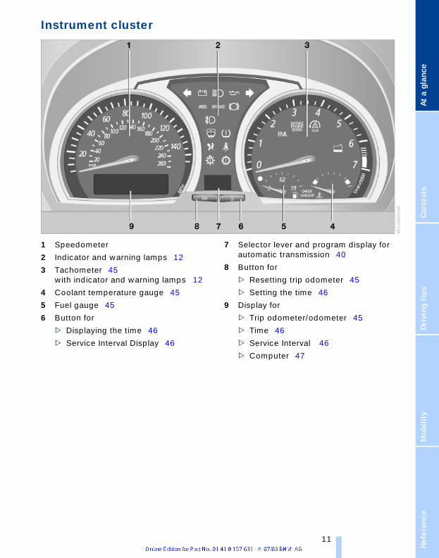
Instrument cluster
1 Speedometer
2 Indicator and warning lamps 12
3 Tachometer 45with indicator and warning lamps 12
4 Coolant temperature gauge 45
5 Fuel gauge 45
6 Button for
> Displaying the time 46
> Service Interval Display 46
7 Selector lever and program display for automatic transmission 40
8 Button for
> Resetting trip odometer 45
> Setting the time 46
9 Display for
> Trip odometer/odometer 45
> Time 46
> Service Interval 46
> Computer 47
Refe 11
Co
ckp
it
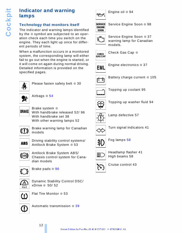
Indicator and warning lampsTechnology that monitors itself The indicator and warning lamps identified by the + symbol are subjected to an oper-ation check each time you switch on the engine. They each light up once for differ-ent periods of time.
When a malfunction occurs in a monitored system, the corresponding lamp will either fail to go out when the engine is started, or it will come on again during normal driving. Detailed information is provided on the specified pages.
Please fasten safety belt + 30
Airbags + 54
Brake system + With handbrake released 52/ 96With handbrake set 38With other warning lamps 52
Brake warning lamp for Canadian models
Driving stability control systems/Antilock Brake System + 53
Antilock Brake System ABS/Chassis control system for Cana-dian models
Brake pads + 96
Dynamic Stability Control DSC/xDrive + 50/ 52
Flat Tire Monitor + 53
Automatic transmission + 39
Engine oil + 94
Service Engine Soon + 98
Service Engine Soon + 37warning lamp for Canadian models.
Check Gas Cap +
Engine electronics + 37
Battery charge current + 105
Topping up coolant 95
Topping up washer fluid 94
Lamp defective 57
Turn signal indicators 41
Fog lamps 58
Headlamp flasher 41High beams 58
Cruise control 43
12

At a
gla
nce
Cont
rols
Driv
ing
tips
Mob
ility
renc
e
ColorsThe indicator and warning lamps can light up in different colors and combinations.
The following section explains the signifi-cance of the individual colors as well as how you should respond when they appear.
> Red:Stop the vehicle immediatelyoran important reminder
> Yellow:Have the system inspected as soon as possibleorfor your information
> Green:For your information
> BlueFor your information.
Refe 13

Co
ckp
it
Buttons in steering wheel*The buttons integrated in the steering wheel are provided so that you can operate a number of accessories quickly and with-out being distracted from traffic conditions. You may operate:> selected audio source functions
> Recirculating air mode/steering wheel heating*
> the cruise control
> some telephone functions
> the voice command system.
In order to operate a system, the cor-responding system must be switched
on.<
Telephone/voice command system
Press briefly:Accept incoming call, start dialing, termi-nate call.Extended pressure:Switch voice command system on and off
Telephone/audio sources
Switching between telephone and radio, cassette, CD or MD
Fast forward/reverse
> Radio Press briefly: next station
> CD Press briefly: skipping tracksMaintain pressure on the button: fast forward/reverse
> Telephone Browse name directory
Volume
Cruise control
Cruise control: calling up
Cruise control: storing and accelerating + as well as braking and storing –
Cruise control: activate/interrupt/deacti-vate
Recirculated-air mode/steering wheel heating
Depending on the equipment, there is a button for the recirculated-air mode
or steering wheel heating.<
Switching the recirculated-air mode and automatic recirculated-air control on and off
Steering wheel heating: switching on/off, refer to page 31.
14

At a
gla
nce
Cont
rols
Driv
ing
tips
Mob
ility
renc
e
Refe 15


ControlsThis chapter is intended to provide you
with information for complete controlof your vehicle. Its extensive array of
features and accessories, both for drivingand for your own safety, comfort and
convenience, are described here.
Op
en
ing
an
d c
losi
ng
Opening and closingKey set
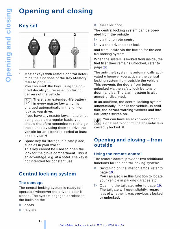
1 Master keys with remote control deter-mine the functions of the Key Memory, refer to page 33.You can mark the keys using the col-ored decals you received on taking delivery of the vehicle
There is an extended-life battery in every master key which is
charged automatically in the ignition lock as you drive.If you have any master keys that are not being used on a regular basis, you should therefore remember to recharge these units by using them to drive the vehicle for an extended period at least once a year.<
2 Spare key for storage in a safe place, such as in your wallet. This key cannot be used to open the lock for the glove compartment. This is an advantage, e.g. at a hotel. The key is not intended for constant use.
Central locking system
The concept The central locking system is ready for operation whenever the driver's door is closed. The system engages or releases the locks on the
> doors
> tailgate
> fuel filler door.
The central locking system can be oper-ated from the outside
> via the remote control
> via the driver's door lock
and from inside via the button for the cen-tral locking system.
When the system is locked from inside, the fuel filler door remains unlocked, refer to page 20.
The anti-theft system is automatically acti-vated whenever you activate the central locking system from outside the vehicle. This prevents the doors from being unlocked via the safety lock buttons or door handles. The alarm system is also armed or disarmed.
In an accident, the central locking system automatically unlocks the vehicle. In addi-tion, the hazard warning flashers and inte-rior lamps switch on.
You can have an acknowledgment signal set to confirm that the vehicle is
correctly locked.<
Opening and closing – from outside
Using the remote controlThe remote control provides two additional functions for the central locking system:
> Switching on the interior lamps, refer to page 19.You can also use this function to locate your vehicle in parking garages etc.
> Opening the tailgate, refer to page 19.The tailgate will open slightly, regard-less of whether it was previously locked or unlocked.
18

renc
eAt
a g
lanc
eCo
ntro
lsDr
ivin
g ti
psM
obili
ty
In addition, the remote control offers you another function:
> Panic mode In case of danger, you can trigger an alarm.
When you engage/release the vehicle locks, you simultaneously activate/deacti-vate the anti-theft system, arm/disarm the alarm system, and switch the interior lamps on/off.
As a reminder that the ignition key is still in the ignition lock after you open
the driver's door, you can have a sound sig-nal set.<
Protect the remote control against unauthorized use by handing over
only the spare key, for example when using hotel valet parking.<
Because any persons or animals left unattended in a parked vehicle could
lock the doors from the inside, you should always take the vehicle's keys with you so that the vehicle can be opened again from the outside at any time.<
UnlockingPress the button.
Press the button once to unlock the driver’s door only; press a second time to unlock all remaining doors as well as the tailgate and the fuel filler door.
Convenience opening modePress and hold the button. The windows and the sliding panel of the panorama glass roof are opened.
Press the button a second time and hold. The panorama glass roof is opened.
If you desire, you can have this spe-cial feature activated/deactivated on
a vehicle-specific basis.<
Locking and securingPress the button.
If you desire, the vehicle locks auto-matically if no door or lid is opened
after unlocking. You may have this function set on a vehicle-specific basis if you wish.<
Switching off the tilt alarm sensor* and interior motion sensor* Press the button once again directly after locking. For details, refer to page 25.
Switching on the interior lampsIf the vehicle is locked, press the button.
Panic mode*By pressing and holding the button for more than approx. two seconds, you can trigger the alarm system in response to any impending danger.
To switch off the alarm: press any of the buttons.
Unlocking tailgatePress the button.
The tailgate will open slightly, regardless of whether it was previously locked or unlocked.
Before and after a trip, ensure that the tailgate has not been opened uninten-
tionally.A previously locked tailgate is also locked after closing.<
If you desire, the tailgate can only be opened using the remote control if the
vehicle is unlocked. This can be adjusted.<
MalfunctionsThe remote control system may be affected by other units or equipment operating in the immediate vicinity of your vehicle. Should the remote control fail to operate owing to interference of this kind, you can respond by using the master key to unlock your vehicle at one of the doors.
In case of faults, please contact your BMW Sports Activity Vehicle Center. You can also obtain replacement keys there.
If it is no longer possible to lock the vehicle via the remote control, the battery is dis-charged. Use this remote control during an extended drive; this will recharge the bat-tery, refer to page 18.
Refe 19

Op
en
ing
an
d c
losi
ng
For US owners onlyThe transmitter and receiver units comply with part 15 of the FCC – Federal Commu-nications Commission – regulations. Oper-ation is governed by the following:
FCC ID: LX8EWS
LX8FZVS
LX8FZVE
Compliance statement:
This device complies with part 15 of the FCC Rules. Operation is subject to the fol-lowing two conditions:
> This device may not cause harmful interference, and
> this device must accept any interfer-ence received, including interference that may cause undesired operation.
Any unauthorized modifications or changes to these devices could void
the user's authority to operate the equip-ment.<
Using the door lock
One turn of the key in the driver's door lock unlocks the driver's door only.Turning the key a second time unlocks all of the remaining doors, the tailgate and the fuel filler door.
You can have a signal set to confirm that the vehicle's locks have engaged
securely.<
Convenience operation You also have the option of operating the windows and the panorama glass roof from the driver's door lock.
> To open: With the door closed, turn the key to the Unlock position and hold it there.
> To close: With the door closed, turn the key to the Lock position and hold it there.
Watch during the closing process to be sure that no one is injured. Releas-
ing the key stops the operation.<
Manual operation In the event of an electrical defect:You can turn the key all the way to the right or left in the door lock to lock or unlock the driver's door.
Opening and closing – from inside
You can use this button to operate the cen-tral locking system when the front doors are closed. With this button, only the doors and the tailgate are unlocked or locked. The anti-theft system is not activated.
If only the driver's door was unlocked from the outside and you press the
button, then, with the driver's door still open, the passenger-side door, the tailgate and the fuel filler door will also unlock.If the driver's door is closed, it will be locked.<
The central locking system locks automatically after driving off. This
can be adjusted to be vehicle-specific or key-specific.<
20

renc
eAt
a g
lanc
eCo
ntro
lsDr
ivin
g ti
psM
obili
ty
Unlocking and opening the doors1. Press the button for central locking sys-
tem
2. Pull the respective door handle above the armrest
or
individually pull on the door handle of each door twice to unlock and open.
Engaging the locks> Press button for central locking system
or
> press down the individual safety lock buttons.
To prevent you from being locked out, the opened driver's door can-
not be locked using the safety lock but-ton.<
Because any persons or animals left unattended in a parked vehicle could
lock the doors from the inside, you should always take the vehicle's keys with you so that the vehicle can be opened again from the outside at any time.<
Tailgate
Opening from outside
Press the button in the handle strip. The tailgate is unlocked and opens somewhat.
During opening, the tailgate pivots upward and to the rear. Ensure that
adequate clearance is available before opening.<
When the tailgate is open, the cargo area and interior are lit up.
Manual unlocking
In the event of an electrical defect:
1. Fold up the floor cover in the cargo area
2. Press the lever to the right.
The tailgate is locked again as soon as you close it.
Closing
The handle recesses on the interior trim of the tailgate make it easier to pull down.
To avoid injuries, be sure that the travel path of the tailgate is clear
when it is closed, as with all closing proce-dures.<
Operate the vehicle only when the tailgate is completely closed. Other-
wise, exhaust fumes could penetrate the interior of the vehicle.<
If special circumstances should make it absolutely necessary to operate the vehicle with the tailgate open:
1. Close all windows and the glass roof
2. Greatly increase the air supply of the air conditioner or automatic climate con-trol, refer to page 60 or 63.
Refe 21

Op
en
ing
an
d c
losi
ng
Electric power windowsOpening and closing windows
As of ignition key position 1:
> Press the switch up to the resistance point:The window continues to move as long as you continue to press the switch
> Press the switch beyond the resistance point:The window moves downward auto-matically. Briefly press the switch again to stop the opening movement.
You can close the windows in the same manner by pulling the switch.
After switching off the ignitionYou can operate the electric power win-dows for up to 15 minutes as long as nei-ther of the front doors has been opened.
When leaving the vehicle parked, always remove the remote control
from the ignition lock and close the doors; this precaution prevents children from operating the electric power windows and injuring themselves, etc.<
For convenience operation with the door lock, refer to page 20.
Anti-trapping mechanismIf the closing force rises beyond a pre-defined threshold during closing, the sys-tem will immediately stop moving the win-dow prior to lowering it slightly.
Despite the anti-trapping mechanism you should always inspect the win-
dow's travel path prior to closing it, as the safety system might fail to detect certain
kinds of obstructions, such as very thin objects, and the window would continue closing.You can disable the anti-trapping mecha-nism by pressing the switch beyond the resistance point and holding it.<
Following interruptions in electrical power supplyAfter disconnecting the battery, the anti-trapping mechanism must be reinitialized. To do this, open and close the windows once and continue pull the switch for 2 sec-onds after closing.
Safety switch
With the safety switch, you can prevent the rear windows from being opened or closed via the switches in the rear passenger area, by children, for example. The indicator lamp lights up when this safety feature is activated.
Press the safety switch whenever children are riding in the rear of the
vehicle. Careless use of the electric power windows can lead to injury.<
You can deactivate the function again as of ignition key position 1.<
Accessories in the window areaAfter installing any accessory – such as a clamp-on antenna for a portable phone – within the window's travel range, you will need to have the system reinitialized for use under the new conditions. Please con-tact your BMW Sports Activity Vehicle Cen-ter.
22

renc
eAt
a g
lanc
eCo
ntro
lsDr
ivin
g ti
psM
obili
ty
Panorama glass roof*
To prevent injuries, exercise care when closing the panorama glass roof
and keep it in your field of vision until it is shut.When leaving the vehicle, always remove the remote control and close the doors to prevent children from operating the glass roof and injuring themselves, etc.<
Raising, opening, closing
The glass roof and sliding panel are opera-tional as of ignition key position 1.
After the ignition has been switched off:You can operate the panorama glass roof for up to 1 minute as long as neither of the doors has been opened.
Opening the glass roof and sliding panel togetherWithin 2 seconds, push the switch back-ward twice beyond the resistance point.The glass roof moves to the convenience position and the sliding panel opens com-pletely. To open the glass roof fully at a standstill, slide the switch backward beyond the resistance point.
Sliding the switch again stops the motion.
Closing the glass roof and sliding panel togetherWithin 2 seconds, push the switch forward twice beyond the resistance point.The glass roof and sliding panel close com-pletely.
Sliding the switch again stops the motion.
Operating sliding panel> Opening, closing:
Slide the switch up to the resistance point in the desired direction.
The motion continues for as long as the switch is held
> Automatic opening, closing:Slide the switch beyond the resistance point in the desired direction.
Sliding the switch again stops the motion.
Operating glass roof> Opening, closing:
Slide the switch up to the resistance point in the desired direction.
The motion continues for as long as the switch is held
> Automatically in convenience position:Slide the switch beyond the resistance point in the desired direction.
In the convenience position, the glass roof is not fully opened.
Sliding the switch again stops the motion.
> Automatic opening and closing:Slide the switch beyond the resistance point in the desired direction. The glass roof moves initially into the conven-ience position. To open or close fully at a standstill, slide the switch beyond the resistance point in the desired direc-tion.
Sliding the switch again stops the motion
> To raise: slide switchTo lower: slide switch forward.
Sliding the switch again stops the motion.
Ventilation settingIn the ventilation setting, the glass roof is raised and the sliding panel opens to a gap: Press the switch twice within 2 seconds.
Pressing the switch again stops the motion.
Refe 23
Op
en
ing
an
d c
losi
ng
If the glass roof and sliding panel areclosed: Press the switch once.<
Anti-trapping mechanismIf the glass roof and sliding panel encoun-ter resistance when closing from roughly one third of the roof opening or when clos-ing from the raised position, the closing action is interrupted and the glass roof and sliding panel reopen a little.
Despite the anti-trapping mechanism you should always inspect the roof's
travel path prior to closing it, as the safety system might fail to detect certain kinds of obstructions, such as very thin objects, and the window would continue closing.The anti-trapping mechanism for closing the panorama glass roof is deactivated if the switch is pressed beyond the resis-tance point and held there. The closing action is interrupted when you release the switch.<
Following interruptions in electrical power supplyFollowing interruptions in electrical power, for instance, when the battery is discon-nected, it is possible that the glass roof will extend to its tilt-up position, but fail to respond to other commands. For initializa-tion, please contact your BMW Sports Activity Vehicle Center.
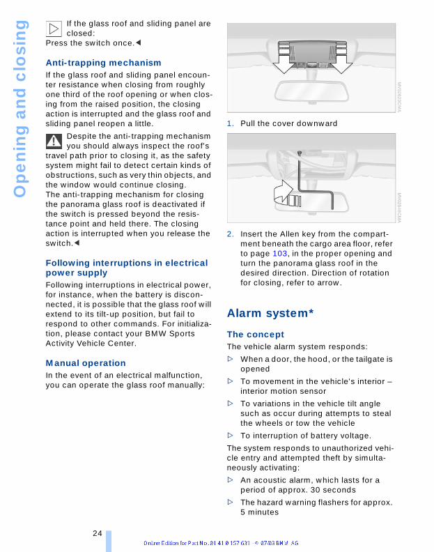
Manual operationIn the event of an electrical malfunction, you can operate the glass roof manually:
1. Pull the cover downward
2. Insert the Allen key from the compart-ment beneath the cargo area floor, refer to page 103, in the proper opening and turn the panorama glass roof in the desired direction. Direction of rotation for closing, refer to arrow.
Alarm system*
The conceptThe vehicle alarm system responds:
> When a door, the hood, or the tailgate is opened
> To movement in the vehicle's interior – interior motion sensor
> To variations in the vehicle tilt angle such as occur during attempts to steal the wheels or tow the vehicle
> To interruption of battery voltage.
The system responds to unauthorized vehi-cle entry and attempted theft by simulta-neously activating:
> An acoustic alarm, which lasts for a period of approx. 30 seconds
> The hazard warning flashers for approx. 5 minutes
24

renc
eAt
a g
lanc
eCo
ntro
lsDr
ivin
g ti
psM
obili
ty
> The high beams, which flash on and off in the same rhythm.
Arming and disarming the alarm systemWhen the vehicle is locked or unlocked with the key or the remote control, the alarm system is also simultaneously armed or disarmed.
If the alarm system has been properly armed, the hazard warning flashers light up once.
You can have different acknowledg-ment signals set to confirm arming
and disarming.<
You can also open the tailgate with the sys-tem armed using the button on the remote control, refer to page 19. When you close the tailgate, the system is rearmed.<
Switching off the alarm> Unlock the vehicle using the remote
control, refer to page 19
> Turn the ignition key to position 1.
Indicator lamp displays
> The indicator lamp below the interior rearview mirror flashes continuously: the system is armed
> The indicator lamp flashes during arm-ing: door(s), the hood or tailgate are not completely closed. Even if you do not close the alerted area, the system begins to monitor the remaining areas, and the indicator lamp flashes continu-ously after 10 seconds. However, the interior motion sensor is not activated
> If the indicator lamp goes out when the system is disarmed: no manipulation or attempted intrusions have been detected in the period since the system was armed
> If the indicator lamp flashes for 10 sec-onds after the system is disarmed: an attempted entry has been detected in the period since the system was armed.
Following triggering of an alarm, the indica-tor lamp will flash continuously.
Avoiding unintentional alarms The tilt alarm sensor and interior motion sensor may be switched off at the same time. You can do this to prevent a false alarm from being triggered in garages with elevator ramps, for instance, or when the vehicle is transported by trailer or train:
Lock twice:
> Press the button on the remote control twice consecutively
> Lock using the door lock twice.
The indicator lamp lights up briefly and then flashes continuously. The tilt alarm sensor and the interior motion sensor are deactivated as long as the system is armed.
If you wish, the tilt alarm sensor and interior motion sensor are perma-
nently switched off. You can have this set at your BMW Sports Activity Vehicle Cen-ter.<
Interior motion sensor In order for the interior motion sensor to function properly, the windows and pan-orama glass roof must be completely closed.
However, be sure to switch off the interior motion sensor – refer to Avoiding uninten-tional alarms – when you
> leave children or animals in the vehicle
> the windows or panorama glass roof are to remain open.
The tilt alarm sensor and interior motion sensor are switched off inad-
Refe 25

Op
en
ing
an
d c
losi
ng
vertently if convenience closing of windowsand panorama glass roof is interrupted within the first 10 seconds and then reiniti-ated. If this has occurred, the system must be disarmed and then rearmed.<
26

renc
eAt
a g
lanc
eCo
ntro
lsDr
ivin
g ti
psM
obili
ty
Adjustments
Sitting safelyThe ideal sitting position can make a vital contribution to relaxed driving that is as fatigue-free as possible. The sitting posi-tion plays an important role together with the safety belts and airbags in providing occupants with maximum levels of passive safety in an accident. Therefore, observe the following instructions, as otherwise the protective function of the safety systems may be impaired.
For additional information on transporting children safely, refer to page 34.
Sitting safely with airbagsAlways maintain an adequate dis-tance between yourself and the air-
bags. Always hold the steering wheel by its rim with hands at the 9 o'clock and 3 o'clock positions, to minimize the risk of injuries to your hands and arms in the event of airbag deployment. No one and nothing is to come between the airbags and the seat occupant. Do not use the cover of the front airbag on the front passenger side as a storage area. Make sure that the front passenger is cor-rectly seated, i.e. feet or legs not resting on the instrument panel, as otherwise leg inju-ries can result if the knee and front airbag is triggered.Never let an occupant's head rest near or on a side airbag because the inflating air-bag could cause a serious or fatal injury.<
Even if you adhere to all the instructions injuries resulting from contact with airbags cannot be fully excluded, depending on the circumstances. The ignition and inflation noise may provoke a mild – usually tempo-rary – hearing loss in extremely sensitive individuals.
For airbag locations and additional infor-mation on airbags, refer to page 54.
Sitting safely with safety beltsEven though there is an airbag, wear a safety belt every time you get in the vehi-cle. Although airbags enhance safety by providing added protection, they are not a substitute for safety belts.
Your vehicle has five seats that are all equipped with a safety belt.
Occupants should sit upright and be properly restrained at all times:
infants and small children in appropriate child-restraint systems; larger children and adults using the safety belts.Expectant mothers should always wear their safety belts, taking care to position the lap belt against the lower hips, where it will not exert pressure against the abdomi-nal area. Never allow more than one person to wear a single safety belt. Never allow infants and small children to ride in a passengers lap.Do not route the belt across your neck, or run it across sharp edges. Be sure that the belt does not become caught or jammed. Avoid twisting the belt while routing it firmly across the hips and shoulder. Do not allow the belt to rest against hard or fragile objects. Otherwise, in the event of a frontal impact, a loose lap belt could slide over your hips, leading to abdominal injury. Avoid wearing clothing that prevents the belt from fitting properly and pull the lap belt periodically to readjust the tension across your shoulder in order to avoid a reduction in the retention effect of the safety belt.<
For fastening safety belts, refer to page 30.
Seats
Note before adjustingNever try to adjust your seat while operating the vehicle. The seat could
respond with unexpected movement, and
Refe 27

Ad
just
me
nts
the ensuing loss of vehicle control couldlead to an accident. Especially on the passenger's side, do not incline the backrest too far to the rear while the vehicle is being driven, as otherwise there is a danger in the event of an accident of sliding under the safety belt, eliminating the protection normally provided by the belt.<
Please observe the information on using safety belts provided on page 30 and the information on the head restraints on page 28.
Seat adjustmentTo ensure that the safety systems continue to provide optimized protec-
tion, please observe the adjustment instructions above.<
1 Longitudinal direction Pull the lever and slide the seat into the desired position.After you release the lever, move the seat forward or backward slightly so that it engages fully
2 HeightPull the lever and apply weight to or remove weight from the seat as required
3 Backrest anglePull the lever and apply weight to or remove weight from the backrest as required
Adjusting the BMW sports seat*
You can also adjust the tilt and the thigh support:
1 Upward tilt:Pull the lever as many times as required to set the desired tilt
2 Downward tilt:Press the lever as many times as required to set the desired tilt
3 Thigh support:Pull the lever and move the thigh sup-port in the longitudinal direction
Head restraintsAlign the head restraints so that their center is approximately at ear level,
as otherwise the risk of spinal injuries is increased in the event of an accident.<
28
renc
eAt
a g
lanc
eCo
ntro
lsDr
ivin
g ti
psM
obili
ty
Adjustments
Height adjustment: pull or press.
To reach the lowest positions, press button 1.<
To adjust the front head restraint tilt angle: adjust by tilting.
Removal – front 1. Pull the head restraint upward to the
stop
2. Press button 1 and remove the head restraint.
Installation – front 1. Press button 1 and slide the head
restraint into its supports
2. Adjust the head restraint.
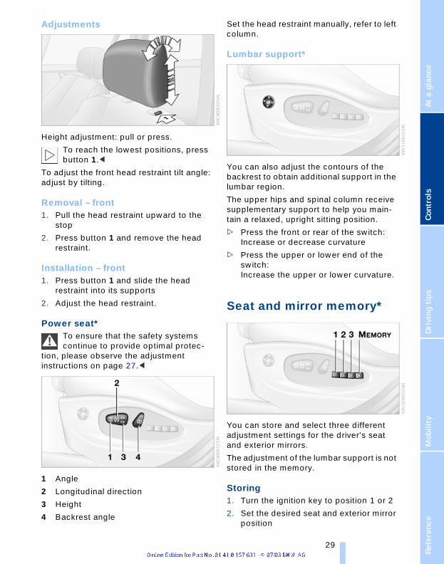
Power seat*To ensure that the safety systems continue to provide optimal protec-
tion, please observe the adjustment instructions on page 27.<
1 Angle
2 Longitudinal direction
3 Height
4 Backrest angle
Set the head restraint manually, refer to left column.
Lumbar support*
You can also adjust the contours of the backrest to obtain additional support in the lumbar region.
The upper hips and spinal column receive supplementary support to help you main-tain a relaxed, upright sitting position.
> Press the front or rear of the switch: Increase or decrease curvature
> Press the upper or lower end of the switch: Increase the upper or lower curvature.
Seat and mirror memory*
You can store and select three different adjustment settings for the driver's seat and exterior mirrors.
The adjustment of the lumbar support is not stored in the memory.
Storing 1. Turn the ignition key to position 1 or 2
2. Set the desired seat and exterior mirror position
Refe 29
Ad
just
me
nts
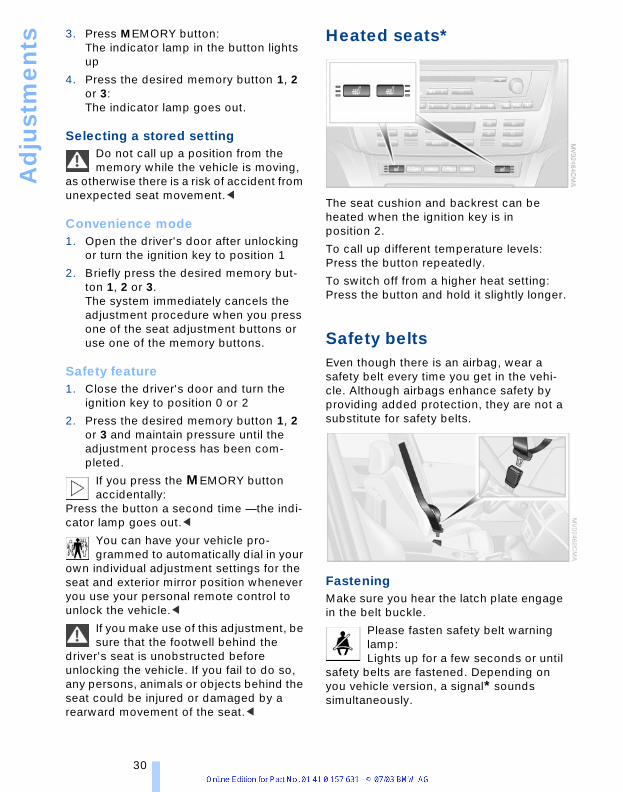
3. Press MEMORY button:The indicator lamp in the button lights up
4. Press the desired memory button 1, 2 or 3: The indicator lamp goes out.
Selecting a stored settingDo not call up a position from the memory while the vehicle is moving,
as otherwise there is a risk of accident from unexpected seat movement.<
Convenience mode1. Open the driver's door after unlocking
or turn the ignition key to position 1
2. Briefly press the desired memory but-ton 1, 2 or 3.The system immediately cancels the adjustment procedure when you press one of the seat adjustment buttons or use one of the memory buttons.
Safety feature1. Close the driver's door and turn the
ignition key to position 0 or 2
2. Press the desired memory button 1, 2 or 3 and maintain pressure until the adjustment process has been com-pleted.
If you press the MEMORY button accidentally:
Press the button a second time — the indi-cator lamp goes out.<
You can have your vehicle pro-grammed to automatically dial in your
own individual adjustment settings for the seat and exterior mirror position whenever you use your personal remote control to unlock the vehicle.<
If you make use of this adjustment, be sure that the footwell behind the
driver's seat is unobstructed before unlocking the vehicle. If you fail to do so, any persons, animals or objects behind the seat could be injured or damaged by a rearward movement of the seat.<
Heated seats*
The seat cushion and backrest can be heated when the ignition key is in position 2.
To call up different temperature levels: Press the button repeatedly.
To switch off from a higher heat setting: Press the button and hold it slightly longer.
Safety beltsEven though there is an airbag, wear a safety belt every time you get in the vehi-cle. Although airbags enhance safety by providing added protection, they are not a substitute for safety belts.
FasteningMake sure you hear the latch plate engage in the belt buckle.
Please fasten safety belt warning lamp:Lights up for a few seconds or until
safety belts are fastened. Depending on you vehicle version, a signal* sounds simultaneously.
30
renc
eAt
a g
lanc
eCo
ntro
lsDr
ivin
g ti
psM
obili
ty
Releasing1. Press the red button in the buckle
2. Hold the belt
3. Guide the belt back into its reel.
The upper shoulder strap's anchorage point will be in the correct position for seat occupants of every build if the seat is cor-rectly adjusted, refer to page 27.
The two rear safety belt buckles integrated in the rear seat are for passengers sitting on the left and right. The belt buckle embossed with the word CENTER is intended exclusively for use by passengers riding in the center position.<
Damage to safety beltsIf the safety belts are damaged or stretched in an accident: have the
entire belt system, including the tensioning mechanisms, replaced at your BMW Sports Activity Vehicle Center. Have the belt anchorage points inspected for damage at the same time. Failure to observe this pre-caution may prevent the safety belts from effectively providing optimal protection when needed. If a child-restraint system was in the vehicle during an accident, con-sult the manufacturer's instructions regard-ing replacement.<
Steering wheel
AdjustmentsDo not adjust the steering wheel while the vehicle is moving. There is a risk
of accident from unexpected movement.<
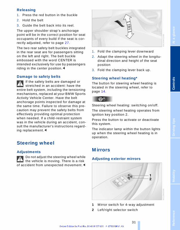
1. Fold the clamping lever downward
2. Adapt the steering wheel in the longitu-dinal direction and height of the seat position
3. Fold the clamping lever back up.
Steering wheel heating* The button for steering wheel heating is located in the steering wheel, refer to page 14.
Steering wheel heating: switching on/off.
The steering wheel heating operates from ignition key position 2.
Press the button to activate or deactivate this system.
The indicator lamp within the button lights up when the steering wheel heating is in operation.
Mirrors
Adjusting exterior mirrors
1 Mirror switch for 4-way adjustment
2 Left/right selector switch
Refe 31

Ad
just
me
nts
To prevent the exterior mirrors on thisvehicle from being damaged, always fold them in by hand before entering an automatic car wash.<
Adjusting manuallyYou can also adjust the mirrors manually:Press the edges of the mirror glass.
Storing the mirror positions, refer to Seat and mirror memory on page 29.
Convex mirrorThe mirror on the passenger's side features a lens with a more convex
surface than the mirror installed on the driver's side. When estimating the distance between yourself and other traffic, bear in mind that the objects reflected in the mirror are closer than they appear. This means that estimations of the distance to following traffic should not be regarded as precise.<
Electric heatersBoth mirrors are heated automatically in ignition key position 2.
Passenger-side exterior mirror tilt function
Automatic curb monitor*1. Select the driver's exterior mirror with
the switch 1
2. When you engage reverse gear or selector-lever position R, the exterior mirror on the front passenger side tilts downward slightly. This allows the driver to see the area immediately adja-cent to the vehicle – such as a curb – when parking, etc.
You can have the angle of downward tilt set in dependence on the key
used.<
Interior rearview mirror
To reduce the dazzle effect of following vehicles at night, turn the knob.
Interior and exterior mirrors, automatic dimming feature*
These mirrors automatically dim through an infinitely-variable range. They automatically revert to their undimmed mode whenever the transmission is placed in reverse gear or selector lever in position R.
For trouble-free operation, keep the photocells unobstructed and clean
and do not cover the area between the interior rearview mirror and the windshield. Do not attach any kind of stickers on the windshield in front of the mirror, either.<
32

renc
eAt
a g
lanc
eCo
ntro
lsDr
ivin
g ti
psM
obili
ty
Vehicle Memory, Key Memory
How the system functions
You have probably frequently wished that you could configure individual functions of your vehicle to reflect your own personal requirements. In developing your vehicle, BMW has incorporated a number of options for personal adjustment. You can have these programmed at your BMW Sports Activity Vehicle Center.
There are vehicle-related and person-related adjustments: Vehicle Memory and Key Memory. You can configure up to four different basic adjustments for four differ-ent persons. The only requirement is that each person uses his or her own master key with remote control.
When your vehicle is unlocked with the remote control, the vehicle recognizes the individual user by means of a data exchange with the key, and makes adjust-ments accordingly.
In order for you to distinguish between the remote control master keys, colored decals are supplied together with the keys.
What the system can do Your BMW Sports Activity Vehicle Center can provide you with details on the capabil-ities of the Vehicle Memory and Key Mem-ory systems.
You will see this symbol throughout the Owner's Manual. It is to remind
you at appropriate places of the settings that are available to you.<
Examples of Vehicle Memory functions> Different acknowledgment signals to
confirm locking/unlocking of the vehi-cle, refer to page 18
> Activate/deactivate function for path-way lighting, refer to page 57
> Activate/deactivate daytime driving lamps, refer to page 57
> Setting measurement units for displays in the instrument cluster of the time, outside temperature, distance driven and fuel consumption, refer to page 47
> Active PDC is indicated by an acoustic sound signal when reverse gear or selector-lever position R is engaged, refer to page 49
> The rear window defroster switches on automatically, refer to page 61
> Different acknowledgment signals to confirm arming/disarming the alarm system, refer to page 25
> After an ice warning has been issued, the display of the computer returns to the previous adjustment, refer to page 47
> Acoustic warning if the ignition key remains in the ignition lock after the driver's door has been opened, refer to page 21.
Examples of Key Memory functions> On unlocking, first unlock the driver's
door, then the entire vehicle, refer to page 19
> Locking the vehicle after moving off, refer to page 20
> Automatic adjustment of the driver's seat and exterior mirror position for each person when unlocking the vehi-cle, refer to page 30
> Angle of downward tilt of mirror on pas-senger side, refer to page 32.
Refe 33

Tra
nsp
ort
ing
ch
ildre
n s
afe
ly
Transporting children safelyThe right place for children
Children always in the rearAccident research shows that the safest place for children in a vehicle is in the rear seat.
Older children should be tightly secured with a safety belt, after they have outgrown a booster seat that is appropriate for their age, height and weight.
A child sitting in the rear seat and not properly restrained may place his or
her head on or near the airbag, if so equipped. For example, a child — even though belted — may fall asleep with his or her head against the side airbag. It may be difficult for a driver to ensure that children in the rear seat will remain properly posi-tioned at all times and do not place their heads on or near the side airbag. There-fore, we recommend that the rear side air-bags, if provided, be deactivated if you plan to transport children in the rear seat.<
Deactivation of the rear seat side airbagsThe rear seat side airbags may already have been deactivated by a BMW Sports Activity Vehicle Center. Labels in the rear door opening should indicate the status of your rear seat side airbags. If you are uncertain of their status, or wish to have the airbags activated or deactivated, please contact your BMW Sports Activity Vehicle Center.
Child-restraint system in rearChildren under 13 years of age and children less than 5 ft/150 cm tall
should always ride in the rear and the restraint systems should be properly adjusted.<
Younger children should be secured in an appropriate forward-facing child-restraint
system that has first been properly secured with a safety belt.
All rear seating positions in your vehicle meet the recommendations of SAE J1819, an industry-recommended practice for securing child-restraint systems in motor vehicles.
Exception for the front passenger seat
Should it become necessary to use a child-restraint system on the front
passenger seat, the airbags on the passen-ger's side must be deactivated. The pas-senger airbag indicator lamp above the interior rearview mirror must light up con-tinuously. Otherwise, the front passenger airbags remain active and there is consid-erable risk of injury to children if the airbags are triggered, even with a child-restraint system. In this case, children should be seated in the rear and the system should be checked at your BMW Sport Activity Vehi-cle Center.<
Never install a rearward-facing child-restraint system in the front passen-
ger seat of this vehicle if the passenger air-bag is not deactivated. If you do so, the child could be severely injured when the airbag is triggered.Your vehicle is equipped with an airbag supplemental restraint system for the front passenger. Because the backrest on any rearward-facing child-restraint system – of the kind designed for infants under 1 year and 20 Ibs/9 kg – would be within the air-bag's deployment range, you should never mount such a system in the front passenger seat, since the impact of the airbag against the child restraint's backrest could lead to serious or fatal injuries.<
More information on automatic deactiva-tion of the front passenger airbags, refer to page 55.
34

renc
eAt
a g
lanc
eCo
ntro
lsDr
ivin
g ti
psM
obili
ty
Installing child-restraint systemsBefore installing any child-restraint system or child seat, read the following:
Observe the child-restraint system manufacturer's instructions for instal-
lation and use. Otherwise the degree of protection can be reduced. After an accident, have all parts of the rele-vant vehicle safety belt system checked by a BMW Sports Activity Vehicle Center and replaced if necessary.<
Commercially-available child-restraint sys-tems are designed to be secured with a lap belt or with the lap belt portion of a combi-nation lap/shoulder belt. Improperly or inadequately installed restraint systems can increase the risk of injury to children. Always read and follow the instructions that come with the system.
Child seat security
All of the rear belt retractors and the front passenger's safety belt can be locked for mounting and securing child-restraint sys-tems.
Information regarding this is located near the buckle latch of each safety belt.
To lock the safety belt Pull the entire length of the belt from the belt retractor. Allow the reel to retract the belt somewhat and engage the buckle, then tighten the belt against the child-restraint system. The retraction mechanism is now locked.
To unlock the safety beltRelease the buckle, remove the child-restraint system and allow the belt retractor to reel the belt completely in.
Child-restraint system with tether strap
If you use a child-restraint system with a tether strap, three additional tether anchor-age points have been provided, refer to the arrows in the illustration. Depending on the location selected for seating in the rear passenger area, attach the tether strap to the corresponding anchorage point to secure the child-restraint system, as shown in the illustration below.
Each seating position is fitted with a head restraint.
Outer seating positions:Lift the head restraint and pass the tether strap between the head restraint and the seat back. It is recommended to readjust the head restraint into the lowest possible position.
Center seating position:The head restraint must be adjusted into the lowest possible position. Pass the tether strap over the head restraint.
Refe 35

Tra
nsp
ort
ing
ch
ildre
n s
afe
ly
Adjust the tether strap according to the child-restraint manufacturer'sinstructions.<
LATCH* child-restraint fixingLATCH: Lower Anchor and Tethers for CHildren.
The rear outer seating positions are pro-vided with anchors for a LATCH child-restraint fixing.
Access to anchorage points
The illustrations show the left rear seat as an example. The anchorage points for the LATCH child seat fixing are located behind the cover caps.Remove the cover caps toward the front.Press on to remount.
Canadian models only:The anchorage points for the LATCH child-restraint fixing are identified by buttons.
To fit the child seat fixing LATCH, fol-low the operating and safety instruc-
tions of the manufacturer.<
Before mounting the LATCH child-restraint fixing, remove the cover caps.
1. Engage the center safety belt into the belt buckle
2. Pull the belt away from the area of the child seat fixing.
For drivingWith side airbags in the rear, make sure that children do not lean out of
the child's seat toward the door panel, as otherwise major injuries can result if the side airbags are triggered.<
You can have the rear side airbags perma-nently deactivated.Your BMW Sports Activity Vehicle Center will be happy to advise you.
Child-safety lock of rear doors
Slide down the safety levers on the rear doors:
The door can now be opened from the out-side only.
Safety switch for power windowsAlways press the safety switch for the elec-tric power windows, refer to page 22, when children are in the rear of the vehicle.
36

renc
eAt
a g
lanc
eCo
ntro
lsDr
ivin
g ti
psM
obili
ty
Driving
Ignition lock
0 Steering lockedThe key can only be inserted or removed in this position.
After removing the key, turn the steering wheel slightly to the left or right until you hear the lock engage.
Vehicles with automatic transmission: Only move the selector lever from
position P with the engine running. To turn the key back to position 0 or to remove it, first place the selector lever in position P: Interlock.<
1 Steering unlockedA slight steering wheel movement often makes it easier to turn the key from 0 to 1.
Individual current consumers are ready for operation.
2 Ignition switched onAll vehicle systems are ready for operation.
3 Engine start
EngineDo not allow the engine to warm up while idling. Drive off immediately at moderate engine speed.
Engine idle speed is controlled by the engine computer system. Increased speeds at startup are normal and should
decrease as the engine warms up. If engine speed does not decrease, service is required.
To prevent the battery from discharging, always switch off electrical devices which are not in use and the ignition when the vehicle is not being driven.
Do not run the engine in closed rooms, as otherwise inhaling toxic
exhaust gases can cause unconsciousness and death. The exhaust gases contain car-bon monoxide, an odorless and colorless, but highly toxic gas. Do not leave the vehi-cle unattended with the engine running, since an unattended vehicle with a running engine represents a safety hazard. When driving, standing at idle and while parking take care to avoid possible contact between a hot exhaust system and any highly flammable materials such as hay, leaves, grass, etc. Such contact could lead to a fire, resulting in serious personal injury and property damage.<
Indicator lampsIf the Service Engine Soon indicator lamp comes on either continuously or intermittently, this indicates a
fault in the emissions-related electronic systems. Although the vehicle remains operational, you should have the systems checked by your BMW Sports Activity Vehicle Center at the earliest possible opportunity.
The illuminated indicator informs you of the need for service, not that you need to stop the vehicle. However, the systems should be checked by your BMW Sports Activity Vehicle Center at the next opportunity.
If the indicator blinks or flashes, this indi-cates a high level of engine misfire. Reduce speed and contact the nearest BMW Sports Activity Vehicle Center immediately. Severe engine misfiring over even a short period of time can seriously damage emis-
Refe 37

Dri
vin
g
sion control system components, espe-cially the catalytic converter.Service Engine Soon indicator lamp for Canadian models.
Malfunction in the engine electron-ics. You can continue to drive with
reduced engine output or engine speed. Please have it checked by your BMW Sports Activity Vehicle Center.
Starting the engineWhen starting the engine, do not press the accelerator pedal.
Vehicles with manual transmission:Step on the clutch when starting the
vehicle. A lockout prevents the engine from starting if the clutch is not depressed.<
Do not actuate the starter for too short a time. Do not turn it for more
than approx. 20 seconds. Release the igni-tion key immediately as soon as the engine starts.<
If the engine fails to start on the first attempt, for instance, if it is very hot or cold:
> Press the accelerator pedal halfway down while engaging the starter.
During a cold start at very low tempera-tures, as of approx. +57/–156, at high altitudes over 3,300 ft/1,000 m:
> For the first attempt, run the start for longer, approx. 10 seconds
> Press the accelerator pedal halfway down while engaging the starter.
Avoid frequent starting is quick suc-cession or repeated start attempts in
which the engine does not start. Otherwise, the fuel is not burned or inadequately burned and there is a danger of overheat-ing and damaging the catalytic converter.<
Manual transmission1. Engage the handbrake
2. Gearshift lever in idle position
3. Press the clutch pedal
4. Start the engine.
Before leaving the vehicle with the engine running, place the gearshift
lever in idle position and apply the hand-brake.Never leave an unattended vehicle with the engine running, as such a vehicle repre-sents a potential safety hazard.<
Automatic transmission1. Press the brake pedal
2. Place the selector lever in position P or N
3. Start the engine.
To prevent the vehicle from rolling, always select position P and engage
the handbrake before leaving the vehicle with the engine running. Never leave an unattended vehicle with the engine running, as such a vehicle repre-sents a potential safety hazard.<
Switching off the engineDo not remove the ignition key when the vehicle is moving, as otherwise
the steering could lock.When leaving the vehicle, always remove the ignition key and lock the steering.When parking on downward inclines, apply the handbrake.<
Manual transmissionTurn the ignition key to position 1 or 0.
Automatic transmissionEngage selector-lever position P, turn igni-tion key to position 1 or 0.
HandbrakeThe handbrake is primarily intended to pre-vent the vehicle from rolling while parked; it brakes the rear wheels.
Indicator lampThe indicator lamp lights up from ignition switch position 2 with the handbrake set – an acoustic signal
also sounds when starting off.
38

renc
eAt
a g
lanc
eCo
ntro
lsDr
ivin
g ti
psM
obili
ty
Indicator lamp for Canadian mod-els.
To engage
The lever engages automatically.
To releasePull up slightly on the lever, press the but-ton and lower the lever.
If exceptional circumstances should make it necessary to engage the
handbrake while the vehicle is in motion, do not pull it too strongly. In doing so, con-tinuously press the button of the handbrake lever.Strong application of the handbrake can lead to overbraking of the rear axle and associated 'fishtailing' of the vehicle rear end.The brake lamps do not light up when the handbrake is applied.Vehicles with manual transmission:When parking on inclines, apply the hand-brake, as even engaging the first or reverse gear might not under certain circum-stances secure the vehicle against moving.Vehicles with automatic transmission:Engage selector-lever position P.<
To prevent corrosion and one-sided braking action, occasionally apply the
handbrake lightly when the vehicle is slowly coming to a standstill at a traffic light if the traffic conditions are suitable.<
Manual transmission
While shifting gear in the 5th/6th gear level, make sure that you press the
gearshift lever to the right to prevent inad-vertently selecting a gear in the 3rd/4th gear level. Do not hold the vehicle in place on slopes by slipping or riding the clutch. Use the handbrake instead, since a slipping clutch increases clutch wear.<
Reverse Select only when the vehicle is stationary. Press the gearshift lever to the left to over-come the resistance.
As you do this, the backup lamps will turn on automatically when the ignition key is in position 2.
Automatic transmission with Steptronic*You can drive as with a normal automatic transmission. In addition, you can also shift manually.
If you move the selector lever from position D to the left into gearshift gate M/S, this activates the sports-style shift programs of the automatic transmission. As soon as you move the selector lever slightly towards + or –, the Steptronic shifts gear and manual operation is activated. When you wish to use the automatic transmission mode again, move the selector lever to the right into the D position.
Refe 39

Dri
vin
g
Selector lever positionsP R N D M/S + –
Engine startedThe engine can only be started in selector-lever positions P – Park – or N – Neutral.
Range selectionAn interlock prevents inadvertent gear-shifts into selector-lever positions R and P. To cancel the interlock, press the button on the front of the selector-lever knob.
ShiftlockPress the brake pedal before shifting out of P or N; the shift command will
not be executed unless the brake is applied – Shiftlock.<
To prevent the vehicle from 'creeping' after you select a range, maintain
pressure on the brake pedal until you are ready to start. If you leave the vehicle with the engine running, engage selector-lever position P and apply the handbrake. If you fail to do this, the vehicle could move.Never leave an unattended vehicle with the engine running, as such a vehicle rep-resents a potential safety hazard.<
P ParkSelect only when the vehicle is stationary. The transmission locks to prevent the rear wheels from turning.
R — ReverseSelect only when the vehicle is stationary.
N – NeutralSelect only if your journey is interrupted for a longer period.
D Drive – Automatic shift programThis position is designed for driving under all normal operating conditions. All forward gears are available.
KickdownA kickdown provides you with maximum acceleration and the maximum road speed in position D. Press the accelerator pedal past the increased resistance point at the full-throttle position.
M/S Manual mode and Sport Program
Shifting from D into M/S activates the Sport program and this is indicated with SD in the gear display. The Sport Program is designed for performance-oriented driving.
The first time the selector lever is even slightly touched, the automatic transmis-sion shifts from the Sport program into manual operation. If you start to move the selector lever towards +, the transmission shifts upwards; moving it towards – shifts down-wards. The gear display shows M1 through M5.
Upshifts and downshifts are executed only when they will result in a plausible combi-nation of engine and vehicle speed; thus, for example, a downshift that would cause the engine to overrev will not be executed by the system. The gear selected will
40

renc
eAt
a g
lanc
eCo
ntro
lsDr
ivin
g ti
psM
obili
ty
appear briefly in the instrument cluster fol-lowed by the current gear.
To obtain maximum acceleration, for passing maneuvers, etc., during
operation in the manual mode, use the kickdown or downshift manually.<
Shifting from M/S to the selector-lever positions P, R and N is only possible by going through D.
Possible displays
P R N D SD M1 M2 M3 M4 M5
MalfunctionsIf the indicator lamp lights up, there is a function fault in the transmis-sion system.
While it will remain still possible to move the selector lever to any desired position, the transmission will revert to operation in its default mode with only a limited number of forward gears. Avoid high loads and drive to the nearest BMW Sports Activity Vehicle Center.
Never work in the engine compart-ment with any of the forward or
reverse gears engaged, as the vehicle could start to move.<
Information on jump-starting and towing starts on page 108.
Turn signal indicators/headlamp flasher
1 High beams – blue indicator lamp
2 Headlamp flasher – blue indicator lamp
3 Turn signal indicators – green indicator accompanied by periodic clicking sound from the relay
If the flashing indicator lamp and the clicking from the relay are both faster
than normal, this indicates that one of the turn signal indicator bulbs is defective.<
Signaling brieflyPress the lever up to but not beyond the resistance point. It then returns to the cen-ter position when released.
Washer/wiper system/Rain sensor*
0 Wipers retracted
1 Intermittent or rain sensor operation
2 Normal wipe
3 Fast wipe
4 Brief wipe
Refe 41

Dri
vin
g
5 Serrated dial for adjustment of the wipe interval or the sensitivity of the rain sen-sorRetracted positionThe right wiper is partially concealed by the hood. To move the wipers into a vertical position:
1. Switch on wipers in lever position 1
2. When the wipers are approximately vertical, move the ignition key to position 0.
For changing the wiper blades, refer to page 99.
Fold the wipers back down onto the windshield before you turn the igni-
tion key to position 1 or 2 again. If you do not, they could be damaged.<
Intermittent modeNot on vehicles with rain sensor.
You can set the wipe interval to four stages with the serrated dial 5. In addition, the wipe interval is varied auto-matically depending on road speed.
Rain sensor*The rain sensor is positioned on the wind-shield, directly in front of the interior rear-view mirror.
Deactivate the rain sensor when passing through an automatic car
wash. Failure to do so could result in dam-age caused by undesired wiper activa-tion.<
Activating> Move the lever to position 1 with the
ignition key in position 1 or higher. The wipers travel once across the wind-shield, regardless of the weather condi-tions.
You can leave the lever permanently in position 1 and then only need to activate the rain sensor as of ignition key position 1. To do so:
> Briefly turn the serrated dial 5 or
> Cleaning windshield 1, refer to next section.
Adjust sensitivity: turn the serrated dial 5.
Deactivating> Move lever to position 0.
Normal wipeThe system switches automatically to inter-mittent mode when the vehicle is not mov-ing, not on vehicles with rain sensor.
Fast wipe The wipers operate at normal speed when the vehicle is not moving, not on vehicles with rain sensor.
Cleaning windshield, rear window and headlamps*
0 Wipers retracted
1 To clean windshield and headlamps
2 Rear window wiper intermittent mode
3 Clean the rear window
Do not use the washers if there is any danger that the fluid will freeze on the
windshield. If you do so, your vision could be obscured. To avoid freezing, use a washer fluid antifreeze, refer to page 94. Do not use the washers when the reservoir is empty. This could cause damage to the washer pump.<
Cleaning the windshieldThe system sprays washer fluid against the windshield and activates the wipers for a brief period. The windshield washer nozzles are auto-
42

renc
eAt
a g
lanc
eCo
ntro
lsDr
ivin
g ti
psM
obili
ty
matically heated as of ignition key position 2.
Cleaning headlamps*When the vehicle lighting system is switched on, the headlamps are cleaned at regular and appropriate intervals.
Rear window wiper Rear window wiper in intermittent mode. When reverse gear is engaged, the wiper operates continuously.
You can also program the interval:
1. Briefly move the wiper lever from posi-tion 0 to position 2
2. Wait for desired interval; maximum of 30 seconds
3. Move the wiper lever from position 0 to position 2 again
To change the wiper blades, refer to page 99.
Cruise control*The vehicle maintains and stores the speed that you set as of a speed of approx. 20 mph/30 km/h.
You can use cruise control whenever the system is active while the engine is run-ning.
Indicator lampIndicator lamp in the instrument cluster lights up green:System ready for operation using
the buttons in the steering wheel.
Activating the system
From ignition key position 2: Press button in steering wheel; the indica-tor lamp in the instrument cluster comes on. You are able to use the cruise control.
Do not use the cruise control when driving on winding roads, in heavy
traffic or in poor road conditions – e.g.
snow, rain, ice, loose road surface – that do not permit a constant speed.<
Deactivating system
Press the button repeatedly until the indi-cator lamp in the instrument cluster goes out.The cruise control is also deactivated when the ignition key is turned to position 0. The speed stored in the memory is deleted in the process.
Maintaining and storing speed or accelerating
Briefly press button +:The system maintains and stores the cur-rent vehicle speed. Every time you briefly press the button, the vehicle's speed increases by roughly 1–mph/1 km/h.
Press and hold button +:The vehicle accelerates without pressure on the accelerator pedal. When you release the button, the system maintains and stores the current speed.
If, on a downhill gradient, the engine's braking effect is not sufficient, the
controlled speed can be exceeded. Speed can drop on uphill grades if the engine out-put is insufficient.<
Decelerating
Briefly press button –:Every time you briefly press the button, the vehicle's speed decreases by roughly 1 mph/1 km/h if you are already driving with cruise control.
Press and hold button –:With the cruise control active, the system automatically reduces the throttle opening to slow the vehicle. When you release the button, the system maintains and stores the current speed.
Refe 43

Dri
vin
g
Interrupting the cruise controlWhen the system is activated, press but-ton. The indicator lamp stays on. You can use the cruise control again whenever required by calling up the speed that was stored last.
In addition, the system is automatically interrupted in response to the following conditions:
> When you apply pressure to the brake pedal
> When you apply pressure to the clutch pedal or when you move the automatic transmission selector lever from D to N
> If you exceed or fall below the con-trolled speed for an extended period, by pressing the accelerator, for exam-ple.
Recalling the stored speed
Press button:The vehicle accelerates to and maintains the last speed stored.
44

renc
eAt
a g
lanc
eCo
ntro
lsDr
ivin
g ti
psM
obili
ty
Everything under control
Odometer
1 Odometer
2 Trip odometer
OdometerYou can activate the displays shown in the illustration in ignition key position 0 or with the ignition key removed by pressing the button in the instrument cluster.
Trip odometerTo reset to zero:
1. Ignition key in position 1
2. Press the button until the trip odometer is reset to zero.
Tachometer
Engine speeds in the red warning field must be avoided.
In this range, the fuel supply is interrupted to protect the engine.
Fuel gauge
If the indicator lamp 1 starts to light up con-tinuously, there are approx. 2 gallons/8 liters of fuel in the tank.
Fuel tank capacity: approx. 17.7 gallons/67 liters.
If the tilt of the vehicle varies, when you are driving in mountainous areas, for example, the indicator may fluctuate slightly.
Refuel well before the tank is empty, as otherwise engine functions will not
be ensured and damage can occur if you drive down to the last drop.<
When you switch on the ignition, the indi-cator lamp comes on briefly to confirm that the system is operational.
Coolant temperature gauge
BlueThe engine is still cold. Drive at moderate engine and vehicle speeds.
Refe 45

Eve
ryth
ing
un
de
r c
on
tro
l
Between the blue and red fieldsNormal operating range. The dial may wan-der into the red field.RedComes on while driving: The engine is overheated. Switch off the engine immediately and allow it to cool down.
Checking coolant level, refer to page 96.
When you switch on the ignition, the warn-ing lamp 1 comes on briefly to confirm that the system is operational.
Service Interval Display
Remaining distance until next service dueThe displays shown in the illustration appear for a few seconds as of ignition key position 1 or after starting the engine.
Together with the lettering OILSERVICE or INSPECTION, the next scheduled service and remaining distance to this service is shown in miles/kilometers.The remaining distance is determined on the basis of the past driving style.
A flashing display and a – before the numerical value mean that the service interval has been passed by the displayed number of miles/kilometers. Please make an appointment with your BMW Sports Activity Vehicle Center.
Replacing brake fluidYou can have the month and year for the scheduled brake fluid replacement dis-played by pressing the right button in the instrument cluster while the next sched-uled service is being displayed. With each button touch, the display switches between the scheduled service and scheduled brake fluid replacement.
When the brake fluid replacement is due, the clock symbol also lights up. Please make an appointment with your BMW Sports Activity Vehicle Center.
Immobilization periods in which the battery is disconnected are not taken
into account by the display. Please remem-ber that brake fluid should be changed every two years at the latest, even if the display does not yet indicate that service is required, refer to page 96.<
ClockIf you want to have a permanent clock dis-play, you can also have the time displayed in the display of the car radio, refer to the Owner's Manual for Radio.
You can adjust the clock, also for display in the radio, as follows.
46

renc
eAt
a g
lanc
eCo
ntro
lsDr
ivin
g ti
psM
obili
ty
Setting the time
As of ignition key position 1:
Hours1. Hold button 2 pressed for a few sec-
onds until the hours are displayed and the colon flashes
2. Press button 1 repeatedly until the desired hour is set
Minutes3. Press button 2 to change to the minute
display
4. Press button 1 repeatedly until the desired minutes are set
5. Press button 2 to confirm the time.
The set time is transferred to the display of the radio or displayed in the instrument cluster.
Display modeIgnition key in position 0 or removed:
Press button 1.
The time and display of the miles/kilome-ters appear for a few seconds.
Computer*
Mode selection
As of ignition key position 1, you can call up information from the computer using the button in the turn signal indicator lever. By pressing the button briefly in the direction of the steering column, you can call up a new function for display.
The displays appear in the following order:Time, outside temperature, average fuel consumption, cruising range, average speed.
As of ignition key position 1, the last active setting is displayed.
If you desire, you can display the fol-lowing functions in a different unit.<
Outside temperature
Changing the unit of measure 7/6During the display, hold down the button in the turn indicator lever until the display changes.
Ice warningIf the outside temperature falls below approx. +37.57 /+36, the computer switches automatically to the outside tem-
Refe 47

Eve
ryth
ing
un
de
r c
on
tro
l
perature display. In addition, an acoustic signal sounds and the display flashes for a short time.After an ice warning has been issued, the display returns to the previous
setting. You can have this activated/deacti-vated.<
Please bear in mind that the ice warn-ing does nothing to alter the fact that
glare ice may be present on roads at tem-peratures higher than +37.57/+36, for instance, on bridges and shaded roads.<
Clock
12 or 24 hour modeIf your vehicle is equipped with a computer, you can have the time displayed in the 12 or 24 hour mode.
During the display, hold down the com-puter button in the turn indicator lever until the display changes.
Average fuel consumption
If you press the button in the turn signal indicator lever for a longer period, the cur-rently displayed average value for fuel con-sumption is recalculated from that moment onwards.
Cruising rangeThe cruising range is determined on the basis of the past driving style and the present volume of fuel.
Always refuel as soon as possible once your cruising range falls to
below 30 miles/50 kilometers, as other-wise engine functions are not ensured and damage can occur.<
Average speed If you press the button in the turn signal indicator lever for a longer period, the cur-rently displayed average value for speed is recalculated from that moment onwards.
48

renc
eAt
a g
lanc
eCo
ntro
lsDr
ivin
g ti
psM
obili
ty
Technology for comfort, convenience and safety
Park Distance Control PDC*
The conceptPDC provides extra safety and conven-ience during parking maneuvers. Signal tones indicate the current distance to an object behind or in front of your vehicle. Four ultrasonic sensors in both the bumpers monitor the distance to the near-est object. The front and rear sensors on the corners have a range of approx. 2 ft/60 cm. The two rear middle sensors have a range of approx. 5 ft/1.50 m and the two front mid-dle sensors of approx. 2.6 ft/80 cm.
PDC is a parking aid that can indicate objects when they are approached
slowly, as is usually the case when parking. Avoid approaching objects too fast, other-wise the system may give warning of phys-ical obstacles too late.<
If you are driving with a trailer, the rear sen-sors are unable to make proper measure-ments – so they do not switch on.
Automatic modeAs of ignition key position 2, the system automatically assumes operational status after a few seconds each time you engage reverse gear or selector-lever position R.
Wait this short period before park-ing.<
You can have a signal tone pro-grammed into the system to verify
that the PDC is active.<
Automatic deactivationAfter driving a distance of more than approx. 160 ft/50 m or exceeding a speed of approx. 20 mph/30 km/h, the system switches off and the indicator lamp goes out. You can reactivate the system manu-ally as needed.
Manual mode
Press the button; the indicator lamp comes on.
Manual deactivation Press the button again; the indicator lamp goes out.
Signal tonesThe distance to an object behind the vehi-cle is signaled in accordance with the posi-tion by an intermittent tone from a loud-speaker in the rear-end.The distance to an object in front of the vehicle is signaled by an intermittent tone from a loudspeaker beneath the instrument cluster.As the distance between vehicle and object decreases, the intervals between the tones become shorter. The signal tone becomes continuous once the distance to the near-est object falls to below roughly 1 ft/30 cm.
The warning signal is canceled after approx. 3 seconds when the distance to an object remains constant during this time, if you are moving parallel to a wall, for instance.
MalfunctionThe indicator lamp flashes and a short steady signal tone is sounded.
Switch the system off and have the cause of the malfunction corrected by your BMW Sports Activity Vehicle Center.
Refe 49

Te
ch
no
log
y fo
r c
om
fort
, co
nve
nie
nc
e a
nd
saf
ety
Limits of the systemEven with PDC, final responsibility for estimating the distance between the
vehicle and any obstructions always remains with the driver. Even when sensors are involved, there is a blind spot in which objects cannot be detected. The system is also subject to the physical limits that apply to all forms of ultrasonic measurement, such as those encountered with tow bars and trailer couplings, or thin and wedge-shaped objects etc. Low objects already displayed, e.g. a curb, can also disappear from the detection area of the sensors again before a continuous tone sounds.Loud sources of sound, inside and outside the vehicle, could drown out the PDC sig-nal tone.<
Keep the sensors clean and free of ice or snow in order to ensure that they
will continue to operate effectively.Do not apply high pressure spray to the sensors for a prolonged period of time. Keep the spray at least 4 in/10 cm away from the sensors.<
Driving stability control systemsYour BMW is equipped with an extended array of systems designed to enhance and maintain vehicle stability under extreme conditions. The following section describes these functions based on ABS, DSC, HDC and xDrive.
Antilock Brake System ABSABS enhances active safety by preventing the wheels from locking under braking. The vehicle continues to be steerable during hard braking.ABS also includes Electronic brake-force distribution EBV.Safe braking, refer to page 77.
Electronic brake-force distribution EBVEBV controls the brake system's applica-tion pressure at the rear wheels to ensure stable deceleration.
Dynamic Brake Control DBCThe Dynamic Brake Control actively sup-ports the driver in dangerous braking situa-tions. Quickly pumping the brake pedal increases the braking effect with low pedal pressure so that the shortest possible braking distance is achieved. This system exploits all of the benefits provided by ABS.
Do not reduce the pressure on the brake pedal for the duration of the brake applica-tion. DBC is deactivated when you release the brake pedal.
Dynamic Stability Control DSC
The concept DSC maintains vehicle stability, even in critical driving situations.
The DSC is operational every time you start the engine.
The system optimizes the driving stability during acceleration and when starting from a standstill. The system recognizes any tendency for the vehicle to assume an unstable attitude such as oversteer or understeer; it then counteracts this ten-dency with a combination of graduated reductions in engine torque and selective braking intervention at individual wheels. DSC provides optimal stability within the limits defined by the laws of physics.
The laws of physics cannot be repealed, even with DSC. An appro-
priate driving style always remains the responsibility of the driver. Avoid using the additional safety margin provided by the system as an excuse for taking unneces-sary risks.
Do not make any modifications to the DSC system. Never allow anyone other than authorized professional technicians to carry out service or repairs on the system.<
50
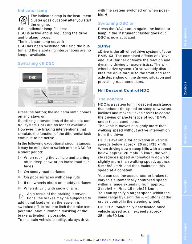
renc
eAt
a g
lanc
eCo
ntro
lsDr
ivin
g ti
psM
obili
ty
Indicator lamp The indicator lamp in the instrument cluster goes out soon after you start the engine.
If the indicator lamp flashes:DSC is active and is regulating the drive and braking forces. The indicator lamp stays lit:DSC has been switched off using the but-ton and the stabilizing interventions are no longer available.
Switching off DSC
Press the button; the indicator lamp comes on and stays on. Stabilizing interventions of the chassis con-trol system DSC are no longer available. However, the braking interventions that simulate the function of the differential lock continue to be active.
In the following exceptional circumstances, it may be effective to switch off the DSC for a short period:
> When rocking the vehicle and starting off in deep snow or on loose road sur-faces
> On sandy road surfaces
> On poor surfaces with deep ruts
> If the wheels churn on muddy surfaces
> When driving with snow chains.
As a result of the braking interven-tions, the brakes may be subjected to
additional loads when the system is switched off. In order to limit the brake tem-perature, brief automatic masking of the brake activation is possible. To maintain vehicle stability, always drive
with the system switched on when possi-ble.<
Switching DSC on Press the DSC button again; the indicator lamp in the instrument cluster goes out. DSC is now activated.
xDrivexDrive is the all-wheel drive system of your BMW X3. The combined effects of xDrive and DSC further optimize the traction and dynamic driving characteristics. The all-wheel drive system xDrive variably distrib-utes the drive torque to the front and rear axle depending on the driving situation and prevailing road conditions.
Hill Descent Control HDC
The concept HDC is a system for hill descent assistance that reduces the speed on steep downward inclines and makes it even easier to control the driving characteristics of your BMW under these conditions.The vehicle moves at slightly more than walking speed without active intervention from the driver.
HDC is available for activation at vehicle speeds below approx. 20 mph/35 km/h. When driving down steep hills with a speed below approx. 20 mph/35 km/h, the vehi-cle reduces speed automatically down to slightly more than walking speed, approx. 5 mph/8 km/h, and then maintains this speed at a constant.
You can use the accelerator or brakes to vary this automatically controlled speed within a range extending from approx. 3 mph/5 km/h to 15 mph/25 km/h.You can specify a target speed within the same range by using the +/– buttons of the cruise control in the steering wheel.
HDC is automatically deactivated once vehicle speed again exceeds approx. 35 mph/60 km/h.
Refe 51

Te
ch
no
log
y fo
r c
om
fort
, co
nve
nie
nc
e a
nd
saf
ety
Activating the systemPress the button; the indicator lamp comes on.
The indicator lamp flashes when the brakes are applied automatically.
Deactivating the systemPress the button again; the indicator lamp goes out.
Above approx. 35 mph/60 km/h HDC is immediately deactivated, and when the ignition is switched off after approx. 10 seconds.
Using HDCOn manual transmission vehicles: Use HDC in first gear and in reverse gear, as in the higher gears the engine braking effect diminishes.
On automatic transmission vehicles:You can use HDC in every drive position.
MalfunctionIf the indicator lamp in the button goes out in the HDC mode or fails to light up when the button is pressed: HDC is temporarily not available, as the brake temperature is too high.
Malfunctions of the driving stability control systems
The red brake warning lamp lights up together with the warning lamps for ABS and DSC/xDrive. In addi-tion, a warning signal sounds:ABS, DSC and xDrive have failed. Drive may then only be carried out via the rear axle. Please have it
checked by the nearest BMW Sports Activ-ity Vehicle Center.
Proceed cautiously and defensively. When driving on poor roads, refrain
from using full throttle and avoid pressing the accelerator beyond the kickdown point. Otherwise the drive train may be damaged or accidents can occur.<
If the brake warning lamp lights up yellow in the described combination, the Electronic brake-force distribution EBV is still avail-able.
Indicator and warning lamps for Canadian models.
The warning lamp in the instrument cluster lights up in yellow.Dynamic Brake Control DBC is
defective. Have the system checked and repaired at your BMW Sports Activity Vehi-cle Center as soon as possible.
Warning lamp for Canadian models.
The warning lamp lights up continu-ously and a warning signal sounds:DSC or the xDrive all-wheel system
has failed. The stabilizing interventions of DSC or the all-wheel drive system xDrive are no longer available. Drive may then only be carried out via the rear axle. Please have it checked by the nearest BMW Sports Activ-ity Vehicle Center.
Proceed cautiously and defensively. When driving on poor roads, refrain
from using full throttle and avoid pressing the accelerator beyond the kickdown point. Otherwise the drive train may be damaged or accidents can occur.<
The warning lamp lights up: Malfunction in the driving stability control systems. HDC is no longer
52

renc
eAt
a g
lanc
eCo
ntro
lsDr
ivin
g ti
psM
obili
ty
available. See your BMW Sports Activity Vehicle Center to have the system repaired.
Flat Tire Monitor
The conceptThe Flat Tire Monitor keeps track of the inflation pressures in the four fitted tires as you drive. The system provides an alert whenever the inflation pressure drops sig-nificantly in relation to the pressure another tire.
The check of the tire inflation pressure is based on monitoring the relative speeds of the wheels. A flat tire is detected and reported on the basis of a deviation in cer-tain speed ratios.
Functional requirementSo that the Flat Tire Monitor can learn the correct inflation pressure, please perform the following:
1. Check the inflation pressures in all tires
2. Compare with the inflation pressure table on page 87 and correct if neces-sary
3. Initialize the system.
Limits of the systemThe Flat Tire Monitor cannot indicate sudden severe tire damage caused
by outside factors and does not detect a natural, even pressure drop in all four tires.<
In the following situations, on the other hand, there can be delays in detecting tire pressure losses, and even system failure:
> When driving on snow-covered or slip-pery road surfaces
> In the case of performance-oriented driving: slip on the drive wheels, high lateral acceleration
> False alarms and undetected loss of pressure may occur when you are driv-ing with snow chains fitted
> When driving with a compact wheel, the Flat Tire Monitor cannot operate.
Initializing the systemPerform the initialization immediately every time you correct the inflation
pressure, change a tire or change a wheel or all wheels. A drive is required for this purpose.<
1. Before the start of driving, start the engine, but do not drive off
2. Press the button until the yellow indica-tor lamp in the instrument cluster lights up for a few seconds
3. Drive off.
It takes a few minutes until the Flat Tire Monitor can detect and indicated a flat tire.
Do not initialize the system when driv-ing with snow chains or with a com-
pact wheel.<
Flat tire
Indicator lampThe symbol in the instrument clus-ter lights up in yellow.
1. Reduce speed and stop the vehicle carefully. Avoid sudden braking and steering maneuvers
2. Identify damaged tire
If identification is not possible, contact your BMW Sports Activity
Vehicle Center.<
3. Replace the damaged tire, refer to Changing a wheel on page 103.
Refe 53
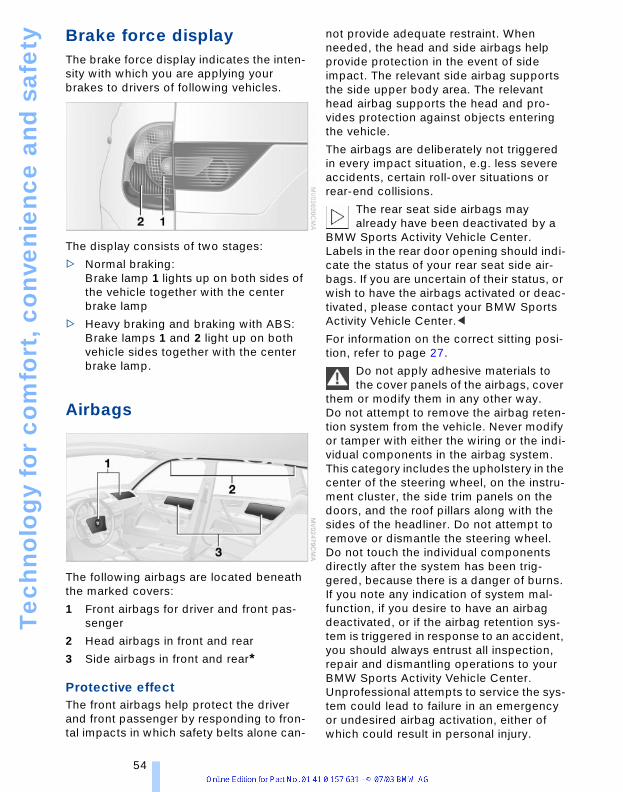
Te
ch
no
log
y fo
r c
om
fort
, co
nve
nie
nc
e a
nd
saf
ety
Brake force displayThe brake force display indicates the inten-sity with which you are applying your brakes to drivers of following vehicles.
The display consists of two stages:
> Normal braking: Brake lamp 1 lights up on both sides of the vehicle together with the center brake lamp
> Heavy braking and braking with ABS:Brake lamps 1 and 2 light up on both vehicle sides together with the center brake lamp.
Airbags
The following airbags are located beneath the marked covers:
1 Front airbags for driver and front pas-senger
2 Head airbags in front and rear
3 Side airbags in front and rear*
Protective effectThe front airbags help protect the driver and front passenger by responding to fron-tal impacts in which safety belts alone can-
not provide adequate restraint. When needed, the head and side airbags help provide protection in the event of side impact. The relevant side airbag supports the side upper body area. The relevant head airbag supports the head and pro-vides protection against objects entering the vehicle.
The airbags are deliberately not triggered in every impact situation, e.g. less severe accidents, certain roll-over situations or rear-end collisions.
The rear seat side airbags may already have been deactivated by a
BMW Sports Activity Vehicle Center. Labels in the rear door opening should indi-cate the status of your rear seat side air-bags. If you are uncertain of their status, or wish to have the airbags activated or deac-tivated, please contact your BMW Sports Activity Vehicle Center.<
For information on the correct sitting posi-tion, refer to page 27.
Do not apply adhesive materials to the cover panels of the airbags, cover
them or modify them in any other way. Do not attempt to remove the airbag reten-tion system from the vehicle. Never modify or tamper with either the wiring or the indi-vidual components in the airbag system. This category includes the upholstery in the center of the steering wheel, on the instru-ment cluster, the side trim panels on the doors, and the roof pillars along with the sides of the headliner. Do not attempt to remove or dismantle the steering wheel.Do not touch the individual components directly after the system has been trig-gered, because there is a danger of burns. If you note any indication of system mal-function, if you desire to have an airbag deactivated, or if the airbag retention sys-tem is triggered in response to an accident, you should always entrust all inspection, repair and dismantling operations to your BMW Sports Activity Vehicle Center. Unprofessional attempts to service the sys-tem could lead to failure in an emergency or undesired airbag activation, either of which could result in personal injury.
54

renc
eAt
a g
lanc
eCo
ntro
lsDr
ivin
g ti
psM
obili
ty
To ensure compliance with official safety regulations, please also entrust disposal of airbag generators to a BMW Sports Activity Vehicle Center.<
Airbag warning information is also provided on the sun visors.
Automatic deactivation of the front passenger airbagsYour BMW has a seat occupation detection system. By evaluating the weight on the front passenger's seat, the system detects whether or not the seat is occupied by a child in the child-restraint system or an adult.
> When a child is seated in the child-restraint system or with an empty seat, the front and side airbags are deacti-vated on the passenger's side
> When an adult is traveling in the front seat, the front and side airbags remain active on the passenger side.
With heavier children, the front pas-senger airbags can remain active, or
with very light adults or teenagers the front passenger airbags can be deactivated unintentionally.The condition of the front passenger air-bags is indicated via the telltale lamp, refer to Indicator lamps in the following. In this case transport the corresponding persons on the rear seat.Except when persons to be transported, do not increase the load on the front passen-ger seat with additional items. Do not fit seat covers, seat cushion padding, ball mats or other items to the front passenger seat unless they are specifically recom-mended by BMW. Do not place any items under the seat. Otherwise, the function of the seat occupation detection could be impaired.<
Indicator/warning lamp
Airbag system operational
The airbag indicator lamp in the instrument cluster indicates the operational readiness of the entire airbag system and the safety belt tensioners as of ignition key position 1.The indicator lamp goes out after a few seconds.
The telltale lamp above the interior rear-view mirror indicates whether the passen-ger airbag system is activated or deacti-vated as of ignition key position 1.
The telltale lamp refers exclusively to the passenger airbag system.<
> The telltale lamp goes out after a few seconds. The front passenger airbags are active, e.g. when transporting an adult
> The telltale lamp lights up continuously. The front passenger airbags are deacti-vated, e.g. when a child is traveling in the vehicle in the child-restraint system or when the seat is empty.
For more information on the operating prin-ciple of the front passenger airbag system and seat occupation detection, refer to Automatic deactivation of the front passen-ger airbags.
Refe 55

Te
ch
no
log
y fo
r c
om
fort
, co
nve
nie
nc
e a
nd
saf
ety
Airbag system malfunctionA system malfunction could prevent the system from responding in the
expected manner to an impact occurring within its normal response range.Please have the airbag system checked immediately by a BMW Sports Activity Vehicle Center.<
There is a fault in the airbag system if the airbag indicator lamp in the instrument cluster behaves as fol-
lows:
> Indicator lamp does not light up as of ignition key position 1
> Indicator lamp remains lit continuously
> Indicator lamp lights up while the vehi-cle is being driven.
56

renc
eAt
a g
lanc
eCo
ntro
lsDr
ivin
g ti
psM
obili
ty
Lamps
Parking lamps/low beams
Parking lamps The front, rear and side vehicle lighting is switched on. You can use the parking lamps for parking. For
lighting on one side for parking as an addi-tional feature, refer to page 58.
Low beams When you switch on the ignition with the headlamps on, the head-lamps go out and only the parking
lamps remain on.
Lamp defectiveThe indicator lamp lights up:At least one bulb of the exterior lighting on the vehicle is defective.
Replacing the bulbs, refer to page 99.
Pathway lighting When you activate the headlamp flasher after parking the vehicle and switching off the lamps, the low beams will come on for a brief period.
You may also have this function deac-tivated if you wish.<
Lights on warning If you turn the ignition key to position 0, an acoustic signal sounds when you open the driver's door for a few seconds to remind you that the light has not yet been switched off.
Daytime driving lamps*You can leave the light switch in the second position: all external lamps go out when you switch off the ignition.
Always observe all applicable laws govern-ing the use of daytime driving lamps.
You can switch on the parking lamps when needed using the standard procedure described under Parking lamps.
You can have the daytime driving lamp circuit activated on your vehi-
cle.<
Automatic headlamp control* When you set the switch to this position, the system activates and switches on and off the low beams
in response to changes in ambient light conditions, for instance, in tunnels, at dawn and dusk, and in rain and snow.
Following automatic activation the vehicle's external lighting remains on
when you switch on the fog lamps.<
Automatic headlamp control cannot serve as a substitute for the driver's
judgment in determining when the vehicle lamps should be switched on. For example, the system cannot detect fog. To avoid safety risks, you should always switch on the lamps manually under these condi-tions.<
You can have the sensitivity of the headlamp control adjusted.<
Adaptive Head Light*
The conceptAdaptive Head Light is a variable headlamp control system that enables dynamic illumi-nation of the road surface. Depending on the steering angle and other assumptions, the light from the headlamp follows the course of the road.
Refe 57

Lam
ps
Activating the Adaptive Head LightIn ignition key position 2, turn the light switch to the position 'Auto-matic headlamp control'.
When the vehicle is backing up, the Adaptive Head Light is inactive; when
the vehicle is at a standstill, it is only active in one direction.<
MalfunctionThe LED above the symbol for automatic headlamp control flashes. Please have it checked by your BMW Sports Activity Vehicle Center.
Instrument lighting
Turn the serrated dial to adjust the illumina-tion intensity.
High beams/standing lamps
1 High beams – blue indicator lamp
2 Headlamp flasher – blue indicator lamp
3 Standing lamps
Standing lamps, left or right*You also enjoy the option of lighting up just one side of your vehicle when parking. When using this function, comply with national regulations:
In ignition key position 0 or with ignition key removed: Allow the lever to engage in the corre-sponding turn signal indicator position.
Fog lamps*
A green indicator lamp appears in the instrument cluster to indicate that the front fog lamps are on.
If the automatic headlamp control is activated, the low beams will come on
automatically when you switch on the fog lamps.<
Interior lamps
The interior lamps operate automatically.
If you desire, the interior lamps are switched on after mechanical unlock-
ing of the vehicle. You may have this func-tion activated/deactivated if you wish.<
58

renc
eAt
a g
lanc
eCo
ntro
lsDr
ivin
g ti
psM
obili
ty
Switching the interior lamps on and off Briefly press button 1.
If you want the interior lamps to remain off all the time, press and hold the button for approx. 3 seconds.
Press the button briefly to revert to normal operation.
You can have soft dimming of the interior lamps set.<
Front reading lamps*Switch on and off with the buttons 2.
Rear reading lamps*
Switch on and off with the button.
Refe 59

A c
on
ge
nia
l clim
ate
A congenial climateAir conditioner
1 Airflow directed toward the windshield and side windows
2 Airflow for the upper body 61
3 Front footwell ventilation 61
4 Air supply/blower 61
5 Outside air/recirculated-air mode 61
6 Temperature 61
7 Air distribution 61
8 Rear window defroster 61
9 Air conditioner 61
60

renc
eAt
a g
lanc
eCo
ntro
lsDr
ivin
g ti
psM
obili
ty
Air supply/blowerYou can select blower speeds 1 to 4. The heating and ventilation become more and more effec-tive as the air supply settings are increased. In position 0, the
blower and heater are switched off. The air supply is blocked in position 0.
TemperatureTo increase the temperature of the interior, turn to the right.
Air distribution You can direct air to flow onto the windows , toward the upper body and into the footwell . All intermediate settings are possible. In the
setting, there is a low flow of air onto the windows to keep them free of condensa-tion.
Rear window defroster When the rear window defroster is activated, the indicator lamp comes on.
The rear window defroster switches off automatically.
You can have your vehicle pro-grammed in such a way that the rear
window defroster switches on automati-cally. It is then switched on at outside tem-peratures of less than approx. +46/397 within 5 minutes of the engine start.<
Air conditioningThe air is cooled and dehumidi-fied and — depending on the temperature setting — warmed
again. Depending on the weather, the windshield may fog over briefly when the engine is started. You can reduce conden-sation forming on the windows by switch-ing on the air conditioning.
During air conditioning condensation forms, which then exits under the
vehicle. Traces of condensed water of this kind are thus normal.<
Outside air/recirculated-air modeYou can respond to unpleasant odors outside the vehicle by temporarily switching off the
outside air supply. The system then recir-culates the air currently within the vehicle.
If condensation starts to form on the inside window surfaces during opera-
tion in the recirculated-air mode, you should switch it off while also increasing air supply as required. The recirculated-air mode should not be used over a sustained longer period of time, as the air quality inside the vehicle deteriorates.<
Ventilation
The air vents for the upper body area can be adjusted:
1 Serrated dials 1 for steplessly opening and closing the air vents
2 Selector levers for airflow direction
3 Use the serrated dial 3 to adjust the amount of cool air that is added to the airflow emerging from the vent outlets for the upper body
Ventilation for coolingAdjust the vents to direct the flow of cool air in your direction, for instance, if the inte-rior has become too warm, etc.
Draft-free ventilationSet the vent outlets so that the air flows past you and is not directed straight at you.
Refe 61
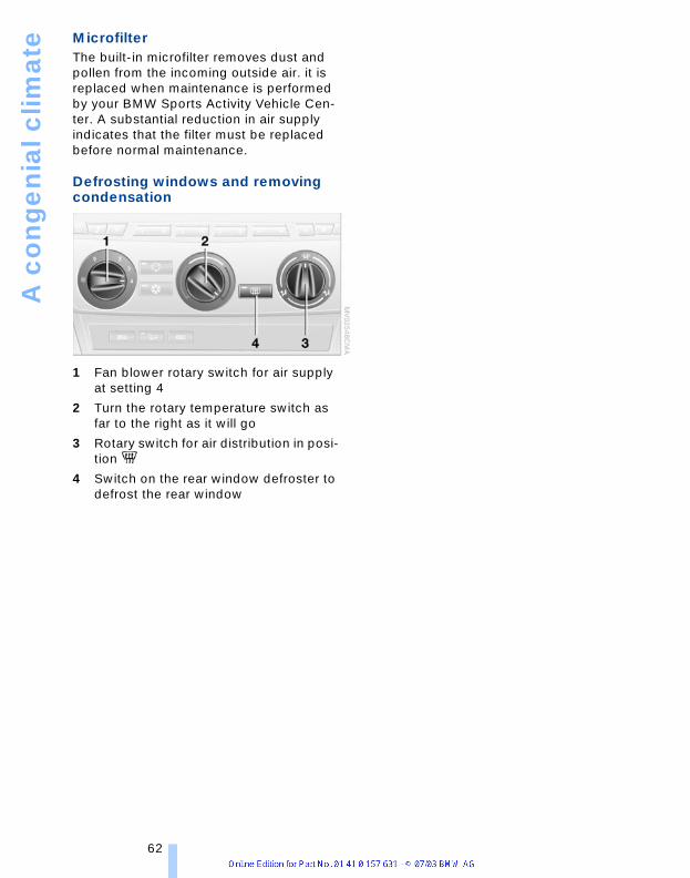
A c
on
ge
nia
l clim
ate
MicrofilterThe built-in microfilter removes dust and pollen from the incoming outside air. it is replaced when maintenance is performed by your BMW Sports Activity Vehicle Cen-ter. A substantial reduction in air supply indicates that the filter must be replaced before normal maintenance.
Defrosting windows and removing condensation
1 Fan blower rotary switch for air supply at setting 4
2 Turn the rotary temperature switch as far to the right as it will go
3 Rotary switch for air distribution in posi-tion
4 Switch on the rear window defroster to defrost the rear window
62

renc
eAt
a g
lanc
eCo
ntro
lsDr
ivin
g ti
psM
obili
ty
Automatic climate control*
1 Airflow directed toward the windshield and side windows
2 Airflow for the upper body 65
3 Air to footwell 65
4 Individual air distribution 64
5 Temperature 64
6 Display for temperature 64 and air supply 64
7 Air supply/blower 64
8 Defrosting windshield and windows and removing condensation 64
9 Rear window defroster 65
10 Air conditioner 64
11 Outside air/AUC Automatic recircu-lated-air control/Recirculated-air mode 64
12 Automatic air distribution and supply 64
Refe 63

A c
on
ge
nia
l clim
ate
A congenial climateUse the automatic facility by operating the AUTO button 12. Select an interior tem-perature that is comfortable for you.
Detailed setting options are described for you in the following section.
Your vehicle has been designed to automatically select your personal cli-
mate-control settings whenever you unlock the doors using your individually pro-grammed remote control.<
If you want, you can have this function deactivated.<
Automatic air distribution and supplyThe AUTO program adjusts the airflow and distribution patterns for you while also using your
preselected temperature setting as the basis for adjusting the interior climate to adapt to external influences – summer, win-ter.
Individual air distributionYou can cancel the AUTO pro-gram by selecting specific air distribution patterns for your personal comfort, the auto-matic air supply remains in operation. You can direct air to
flow onto the windows , toward the upper body , and into the footwell . You can reactivate the automatic air distri-bution mode by selecting the AUTO button.
TemperatureThe figures in the display pro-vide a general indication of inte-rior temperature. When you start the vehicle, this system ensures that the selected tem-perature is achieved as quickly
as possible. It then maintains this tempera-ture, regardless of the season.
Air supply/blowerYou can vary the air supply by pressing the upper or lower button. This switches off the automatic program for the air supply, and the word AUTO
goes out in the display. The automatic mode for air distribution remains in opera-tion as before. You can reactivate the auto-matic air supply mode by selecting the AUTO button.
If you press the lower button when at the lowest blower speed, all displays go out: the blower, heating and air conditioner are switched off. The outside air supply is closed. You can restart the automatic cli-mate control by pressing any of its buttons.
Defrosting windows and removing condensation
This program quickly removes ice and condensation from the windshield and door windows.
Air conditionerThe air is cooled and dehumid-ified and — depending on the temperature setting — warmed
again. Depending on the weather, the windshield may fog over briefly when the engine is started. The window mist is reduced during A/C operation.
The air conditioner comes on automatically when you select the AUTO program.
During air conditioning condensation forms, which then exits under the
vehicle. Traces of condensed water of this kind are thus normal.<
Outside air/AUC Automatic recirculated-air control/Recirculated-air mode
You can respond to unpleasant odors or pollutants in the imme-diate environment by tempo-
rarily suspending the supply of outside air. The system then recirculates the air cur-rently within the vehicle. Press the button
64

renc
eAt
a g
lanc
eCo
ntro
lsDr
ivin
g ti
psM
obili
ty
repeatedly to run through the following control sequence:
> Indicator lamps off: outside air flows into the vehicle
> Left-hand indicator lamp on – AUC mode: the system recognizes pollutants in the outside air and blocks the flow of air when necessary. The system then recirculates the air currently within the vehicle.Depending on the air quality, the auto-matic system then switches back and forth between outside air supply and recirculation of the air within the vehicle
> Right-hand indicator lamp on: the out-side air supply into the vehicle is com-pletely blocked. The system then recir-culates the air currently within the vehicle.
If condensation starts to form on the inside window surfaces during opera-
tion in the recirculated-air mode, you should switch it off while also increasing air supply as required. The recirculated-air mode should not be used over a sustained longer period of time, as the air quality inside the vehicle deteriorates.<
Rear window defroster When the rear window defroster is activated, the indicator lamp comes on.
The rear window defroster switches off automatically.
You can have your vehicle adjusted in such a way that the rear window
defroster switches on automatically. It is then switched on at outside temperatures of less than approx. +46/397within 5 minutes of the engine start.<
Ventilation
The air vents for the upper body area can be adjusted:
1 Serrated dials for opening and closing the vent outlets through an infinitely-variable range
2 Selector levers for airflow direction
3 Use the serrated dial 3 to adjust the amount of cool air that is added to the airflow emerging from the vent outlets for the upper body
Ventilation for coolingAdjust the vents to direct the flow of cool air in your direction, for instance, if the inte-rior has become too warm, etc.
Draft-free ventilationSet the vent outlets so that the air flows past you and is not directed straight at you.
Microfilter/activated-charcoal filter* The built-in microfilter removes dust and pollen from the incoming air. The activated-charcoal filter provides additional protec-tion by filtering gaseous pollutants from the outside air. This combined filter is replaced when maintenance is performed by your BMW Sports Activity Vehicle Center. A substantial reduction in air supply indicates that the filter must be replaced before nor-mal maintenance.
Refe 65

Pra
cti
cal
inte
rio
r ac
ce
sso
rie
s
Practical interior accessoriesIntegrated universal remote control*
The concept The integrated universal remote control replaces up to three different hand-held transmitters for various items of radio-con-trolled equipment such as door openers and house alarm systems. The integrated universal remote control recognizes and learns the transmitted signal of each of the original hand-held transmitters.
The signal of an original hand-held trans-mitter can be programmed on one of the three memory buttons 1. Following that, each of the devices can be actuated with the appropriately programmed memory button 1. The indicator lamp 2 flashes to confirm transmission of the signal.
If the vehicle is sold, the memory of the memory buttons 1 should be cleared, refer to page 67.
To prevent possible damage or injury, before programming or using the inte-
grated universal remote control, always inspect the immediate area to make certain that no people, animals or objects are within the travel range of the device. Also, comply with the safety precautions of the original hand-held transmitter.<
Checking the compatibility If you see this symbol on the pack-aging or in the manual supplied with the original hand-held transmitter, it
is safe to assume that it is compatible with the integrated universal remote control.
If you have additional questions, please consult your BMW Sports
Activity Vehicle Center or call 1-800-355-3515.You can also visit these websites:www.bmwusa.com or www.homelink.com.
HomeLink is a registered trademark owned by Johnson Controls, Inc.<
Programming
1 Memory buttons
2 Indicator lamp
Fixed-code hand-held transmitter 1. Turn the ignition key to position 2
2. For initial use: Press both outer buttons 1 for approx. 20 seconds, maintaining pressure until the indicator lamp 2 starts to flash. The three memory buttons 1 are cleared
3. Hold the original hand-held transmitter at a distance of approx. 2 in/5 cm to 8 in/20 cm to the memory buttons 1
The required distance between the hand-held transmitter and
memory keys 1 depends on the relevant system of the original hand-held trans-mitter used.<
4. Simultaneously press the transmit but-ton on the original hand-held transmit-ter and the desired memory key 1 of the integrated universal remote control. Ini-tially, the indicator lamp 2 flashes slowly. Release both buttons as soon as the indicator 2 lamp flashes rapidly. If the indicator lamp 2 does not flash rap-idly after approx. 15 seconds, change the distance
5. To program other original hand-held transmitters, repeat steps 3 and 4.
66

renc
eAt
a g
lanc
eCo
ntro
lsDr
ivin
g ti
psM
obili
ty
The corresponding memory button 1 is now programmed with the signal of the original hand-held transmitter.
The equipment can be used as of ignition key position 2.
If the device cannot be operated after repeated programming, check
whether the original hand-held transmitter uses an alternating-code system. To do so, either read the instructions of the original hand-held transmitter or press and hold down the programmed memory button 1 of the integrated universal remote control. If the indicator lamp 2 on the integrated uni-versal remote control flashes rapidly for a short time then lights up for approx. 2 sec-onds, this indicates that the original hand-held transmitter uses an alternating-code system. In the case of an alternating-code system, program the memory buttons 1 as described at the section on alternating-code transmitters.<
Alternating-code transmitters Consult the operating instructions of the unit you wish to set when programming the universal remote control. You will find infor-mation there on the possibilities for syn-chronization.When programming hand-held transmitters that employ an alternating code, please observe the following supplementary instructions:
Programming will be easier with the aid of a second person.<
1. Park your vehicle within the range of the remote-controlled device
2. Program the integrated universal remote control as described above at Fixed-code hand-held transmitters
3. Locate the button at the receiver of the equipment to be set, e.g. on the drive
4. Press the button on the receiver of the device you want to set up. After step 4, you have approx. 30 seconds for step 5
5. Press the programmed memory button 1 of the integrated universal remote control three times.
The corresponding memory button 1 is now programmed with the signal of the original hand-held transmitter.
If you have questions, please contact your BMW Sports Activity Vehicle
Center.<
Clearing the memory buttons Press both outer buttons 1 of the inte-grated universal remote control for approx. 20 seconds, maintaining pressure until the indicator lamp 2 starts to flash. All three memory buttons are cleared.
The memory of individual memory buttons 1 cannot be cleared.
Beverage holders
Front
Depending on your optional equipment, the center console contains either one or two beverage holders.
Passenger's side*
The beverage holder for the front passen-ger is located beneath the air/heating vent.
Refe 67

Pra
cti
cal
inte
rio
r ac
ce
sso
rie
s
1. Press the trim piece below the air/heat-ing vent, arrow 12. Insert beverage
3. Adapt the holding arm to the size of the beverage container, refer to arrow 2.
Rear
A beverage holder is located in the center armrest at the rear: Press the button to open.
Glove compartment
Opening
Pull the handle. The lamp inside the glove compartment comes on.
ClosingFold the cover up.
To prevent injury in the event of an accident, close the glove compart-
ment immediately after use.<
LockingUse one of the master keys. A master key is also required for unlocking.
If you only hand over the spare key, e.g. in a hotel for valet parking, refer
to page 18, the glove compartment cannot be accessed.<
Storage compartments
Front center armrest*
The center armrest contains two storage compartments.
> CD storage compartment:Press button 1
> Coin and oddments compartment:Press button 2.
Rear center armrest
A storage compartment holder is located in the center armrest at the rear:
To open, pull the cover upward.
Storage package*Your convenience is enhanced by:
> Sliding lashing eyes in luggage com-partment, refer to page 73
> Floor cover in luggage compartment that can be used on both sides, refer to page 72
68

renc
eAt
a g
lanc
eCo
ntro
lsDr
ivin
g ti
psM
obili
ty
> Nets in the luggage compartment and on the rear of the front seats.
Front ashtray*
Press the edge of the opened cover: The ashtray moves up and can be removed.
On vehicles with the non-smoking pack-age, the insert is removed in the same way.
Cigarette lighter, front*Press the lighter 1 in. The lighter can be removed as soon as it retracts.
Hold or touch the hot cigarette lighter by the knob only. Holding or touching
it in other areas could result in burns. The cigarette lighter remains operational when the ignition key has been removed. For this reason, do not leave unsupervised children in the vehicle.<
Lighter socket The socket can be used to plug in hand flashlights, car vacuum cleaners, etc., with power ratings of up to approx. 200 W at 12 V. Avoid damage to the socket caused by inserting plugs of a different shape or size.
Non-smoking packageOn vehicles with the non-smoking pack-age, the socket is located in the same position.Access to the socket: lift off cap.
SocketsYou will find additional power outlets in the cargo area, refer to page 73.
Ashtray, rear*
Remove the insert tray.
Cigarette lighter, rear*
Depending on your optional equipment, the lighter can be located on the top or end face of the center console.
Press the lighter in. The lighter can be removed as soon as it retracts.
Hold or touch the hot cigarette lighter by the knob only. Holding or touching
it in other areas could result in burns. The cigarette lighter remains operational when the ignition key has been removed. For this reason, do not leave unsupervised children in the vehicle.<
Refe 69
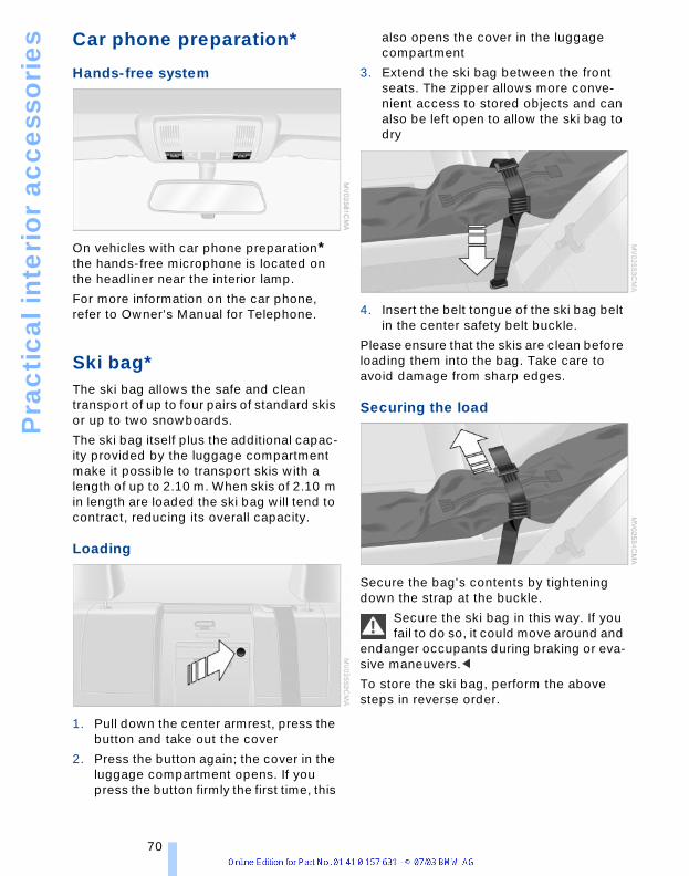
Pra
cti
cal
inte
rio
r ac
ce
sso
rie
s
Car phone preparation*Hands-free system
On vehicles with car phone preparation* the hands-free microphone is located on the headliner near the interior lamp.
For more information on the car phone, refer to Owner's Manual for Telephone.
Ski bag*The ski bag allows the safe and clean transport of up to four pairs of standard skis or up to two snowboards.
The ski bag itself plus the additional capac-ity provided by the luggage compartment make it possible to transport skis with a length of up to 2.10 m. When skis of 2.10 m in length are loaded the ski bag will tend to contract, reducing its overall capacity.
Loading
1. Pull down the center armrest, press the button and take out the cover
2. Press the button again; the cover in the luggage compartment opens. If you press the button firmly the first time, this
also opens the cover in the luggage compartment
3. Extend the ski bag between the front seats. The zipper allows more conve-nient access to stored objects and can also be left open to allow the ski bag to dry
4. Insert the belt tongue of the ski bag belt in the center safety belt buckle.
Please ensure that the skis are clean before loading them into the bag. Take care to avoid damage from sharp edges.
Securing the load
Secure the bag's contents by tightening down the strap at the buckle.
Secure the ski bag in this way. If you fail to do so, it could move around and
endanger occupants during braking or eva-sive maneuvers.<
To store the ski bag, perform the above steps in reverse order.
70

renc
eAt
a g
lanc
eCo
ntro
lsDr
ivin
g ti
psM
obili
ty
Removing the ski bag
Pull the handle forward and remove the ski bag upward.
Do not position cargo at the opening. If you do, it can endanger the passen-
gers during braking or evasive maneu-vers.<
Cargo areaWhen loading, observe the information on page 78.
Folding rear seat back
Reach into the opening and pull forward, refer to arrow.
When you fold back the backrest, be sure that the catch engages securely.
The red warning indicator disappears in the recess when the catch is engaged.<
Ski bag*To create a flat load area floor, you can remove the ski bag before folding the rear seat back and replace it with a cover. You will find the cover in the cargo area under the floor cover.
Cargo area cover
Pull the cargo area cover out by the handle and hook it in the rear holders.
You can carry light objects such as articles of clothing on the cargo area cover.
Do not place heavy and hard objects on the cover. If you do so, they could
endanger occupants during braking maneuvers. Do not allow the cover to snap back into place, as otherwise it could be damaged.<
Removal
1. Press the side buttons, refer to arrow 1
2. Pull the cassette towards the rear, refer to arrow 2.
InstallationPush the cassette forward into the two side holders until it locks in place.
Refe 71
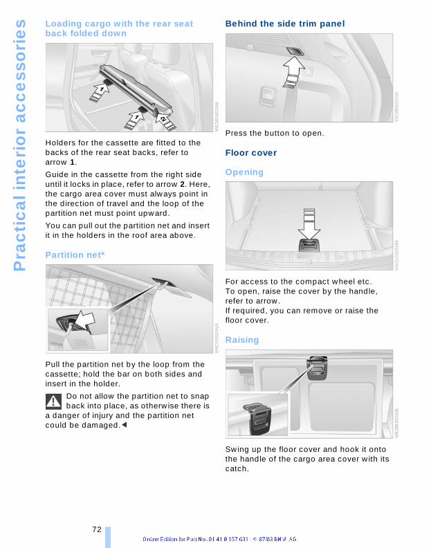
Pra
cti
cal
inte
rio
r ac
ce
sso
rie
s
Loading cargo with the rear seat back folded downHolders for the cassette are fitted to the backs of the rear seat backs, refer to arrow 1.
Guide in the cassette from the right side until it locks in place, refer to arrow 2. Here, the cargo area cover must always point in the direction of travel and the loop of the partition net must point upward.
You can pull out the partition net and insert it in the holders in the roof area above.
Partition net*
Pull the partition net by the loop from the cassette; hold the bar on both sides and insert in the holder.
Do not allow the partition net to snap back into place, as otherwise there is
a danger of injury and the partition net could be damaged.<
Behind the side trim panel
Press the button to open.
Floor cover
Opening
For access to the compact wheel etc.To open, raise the cover by the handle, refer to arrow. If required, you can remove or raise the floor cover.
Raising
Swing up the floor cover and hook it onto the handle of the cargo area cover with its catch.
72

renc
eAt
a g
lanc
eCo
ntro
lsDr
ivin
g ti
psM
obili
ty
Lashing eyes, rail*
You can secure load-securing devices to the lashing eyes on the cargo area floor.
To shift the lashing eyes, press the button. The lashing eyes can be removed at the openings in the rails.
Read and comply with the information enclosed with the load-securing
devices.<
Sockets
When the cover is folded up, you have access to another socket.
The sockets can be used to plug in hand flashlights, car vacuum cleaners, etc., with power ratings of up to approx. 200 W at 12 V. Do not damage the socket with unsuitable plugs, also refer to page 69.
Refe 73
Driving tipsThis section is designed to provide you
with extra support by supplying informationuseful in dealing with specific driving and
operating conditions.

Th
ing
s to
re
me
mb
er
wh
en
dri
vin
g
Things to remember when drivingBreak-in proceduresTo ensure that your vehicle provides maxi-mum economy throughout a long service life, we request that you observe the fol-lowing instructions:
Engine and differentialUp to 1,200 miles/2,000 km: During this initial period you should attempt to avoid constant, steady-state operation and vary both vehicle and engine speeds as often as possible. Until the break-in period has been completed you should also refrain from exceeding the following:
> 4,500 rpm or 100 mph/160 km/h.
Always obey all official speed limits.
Refrain from using full throttle and avoid pressing the accelerator beyond the kick-down point.
Once you have driven 1,200 miles/2,000 km, the engine and vehicle speeds can be gradually increased.
You should also comply with these break-in procedures should the engine or one of the differentials be replaced later in the course of the vehicle's service life.
TiresDue to technical factors associated with their manufacture, tires do not achieve their full traction potential until after an initial break-in period. For this reason, drive with extra care during the initial 200 miles/300 km.
Obey your local and state maximum speed limits.
When the vehicle is operated on wet or slushy roads, a wedge of water
may form between the tire and the road surface. This phenomenon is referred to as hydroplaning and can lead to partial or complete loss of traction, vehicle control and braking effectiveness. Reduce your speed on wet roads.<
Brake systemApprox. 300 miles/500 km must elapse before the brake pads and rotors achieve the optimal pad-surface and wear patterns required for trouble-free operation and long service life later on.
To break in the separate handbrake drums, apply the handbrake lightly when coasting to a standstill – at a traffic signal, for instance; use caution to avoid posing a danger to other road users.
To avoid corrosion, repeat this procedure from time to time.
The brake lamps do not come on when the handbrake is set.
Vacuum for the brake system servo unit on your BMW is available only
when the engine is running. When you move the vehicle with the engine off – e.g. by towing – substantially higher levels of pedal force will be required to brake the vehicle.<
ClutchThe function of the clutch is also only at its optimized level after a distance driven of approx. 300 miles/500 km. During this break-in period, engage the clutch gently.
General driving notes
High temperatures Extreme temperatures occur at the catalytic converter on this and every
catalyst-equipped vehicle. Do not remove the heat shields installed adjacent to vari-ous sections of the exhaust system, and never apply undercoating to them. When driving, standing at idle and while parking take care to avoid possible contact between the hot exhaust system and any highly flammable materials such as hay, leaves, grass, etc. Such contact could lead
76
renc
eAt
a g
lanc
eCo
ntro
lsDr
ivin
g ti
psM
obili
ty
to a fire, and with it the risk of serious prop-erty damage as well as personal injury.<
Parking the vehicle Condensation forms in the air conditioner system during operation, and then exits under the vehicle. Traces of condensed water under the vehicle are thus normal.
Before driving into the car wash Fold in the exterior mirrors, refer to page 31, as otherwise they could be dam-aged due to the width of the vehicle. Deactivate the rain sensor as otherwise damage could result from undesired wiper activation, refer to page 42.
HydroplaningWhen driving on wet or slushy roads, reduce road speed. If you do not, a
wedge of water can form between tires and road surface. This phenomenon is referred to as hydroplaning, and is characterized by a partial or complete loss of contact between tires and road surface, ultimately undermining your ability to steer and brake the vehicle.<
Driving through waterDo not drive through water on the road if it is deeper than 20 in/50 cm,
and then only at walking speed. Otherwise, the vehicle's engine, the electrical systems and the transmission may be damaged.<
Safe braking
Emergency stopsThe best way to brake is to apply maximum pressure to the brake pedal during emer-gency – panic stops. Since the vehicle maintains steering responsiveness, you can nevertheless avoid possible obstacles with a minimum of steering effort.
Pulsation at the brake pedal combined with sounds from the hydraulic circuits indicates to the driver that ABS is in its active mode.
Do not drive with your foot resting on the brake pedal. Otherwise, even light
but consistent pedal pressure can lead to high temperatures, brake wear and possi-bly even brake failure.<
Wet conditions While driving in wet conditions and in heavy rain, it is a good idea to apply light pressure to the brake pedal every few miles. Watch traffic conditions to ensure that this maneuver does not endanger other road users. The heat which is gener-ated by the brake applications helps to dry the brake pads and rotors. The required braking force will then be available when you need it.
On a gradeYou can retain full and unimpaired braking efficiency by downshifting to a gear in which only minimal brake applications are needed when descending long or steep downhill stretches.
You can further enhance the engine's brak-ing effect by selecting a lower gear in the automatic transmission's manual mode, downshifting as far as first gear on extremely steep stretches, refer to page 38. This strategy helps you avoid placing excessive loads on the brake sys-tem.During slower downhill driving, use the Hill Descent Control HDC, refer to page 51.
Never drive with the clutch pressed, with the transmission in Neutral or
with the engine switched off, as otherwise there is no engine braking when the trans-mission is in Neutral, and no power-assist for brakes and steering. Never allow floor mats, carpets or any other objects to protrude into the area around the accelerator and brake pedals and obstruct their movement.<
CorrosionWhen the vehicle is driven only occasion-ally, during extended periods when the vehicle is not used at all, and in operating conditions where brake applications are
Refe 77

Th
ing
s to
re
me
mb
er
wh
en
dri
vin
g
less frequent, there is an increased ten-dency for corrosion to form on rotors, while contaminants accumulate on the brake pads. This occurs because the minimal pressure which must be exerted by the pads during brake applications to clean the rotors is not reached.Should corrosion form on the brake rotors, the brakes will tend to respond with a pul-sating effect that even extended applica-tion will fail to cure.
Cargo loading To avoid loading the tires beyond their approved carrying capacity,
never overload the vehicle. Overloading can lead to overheating and increases the rate at which damage develops inside the tires. The ultimate result can assume the form of a sudden air loss.<
Determining the load limit
1. Locate the following statement on the driver's door pillar:
The combined weight of occu-pants and cargo should never
exceed XXX lbs or YYY kg. Failure to observe this can compromise your vehicle's driving stability and cause vehicle damage.<
2. Determine the combined weight of the driver and passengers that will be riding in your vehicle
3. Subtract the combined weight of the driver and passengers from XXX pounds or YYY kilograms
4. The resulting figure equals the available amount of cargo and luggage load capacity.For example, if the XXX amount equals 1,400 lbs and there will be five 150-lbs passengers in your vehicle, the amount of available cargo and luggage load capacity is 650 lbs:1,400 lbs minus 750 lbs = 650 lbs
5. Determine the combined weight of lug-gage and cargo being loaded on the vehicle. That weight should never exceed the available cargo and luggage load capacity calculated in Step 4
6. If your vehicle will be towing a trailer, part of the load from your trailer will be transferred to your vehicle. Consult the manual for transporting a trailer to determine how this may reduce the available cargo and luggage load capacity of your vehicle.
LoadThe permitted load is the total of the weight of occupants and cargo/luggage. The greater the weight of occupants, the less cargo/luggage can be transported.
78
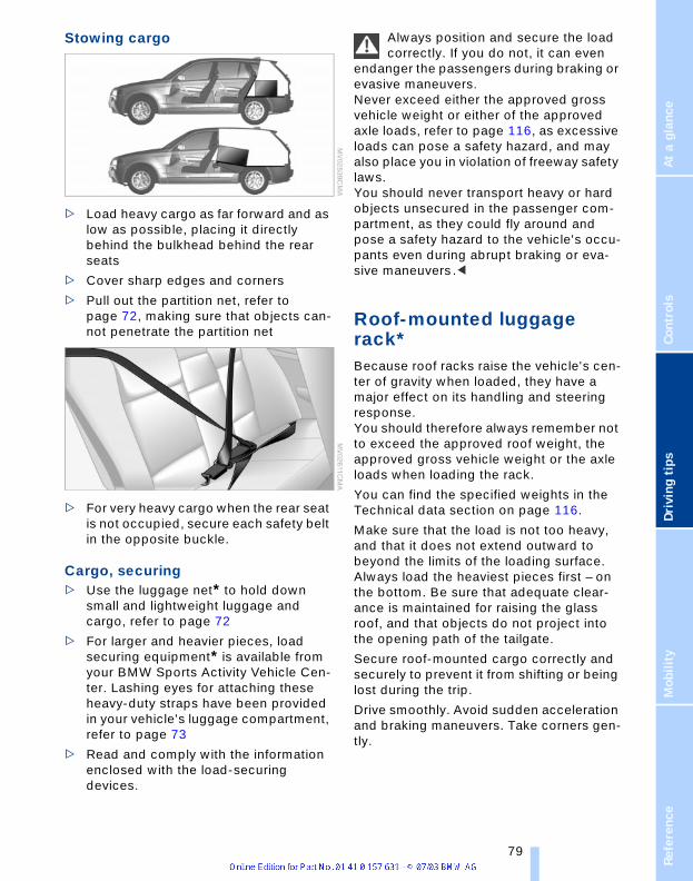
renc
eAt
a g
lanc
eCo
ntro
lsDr
ivin
g ti
psM
obili
ty
Stowing cargo
> Load heavy cargo as far forward and as low as possible, placing it directly behind the bulkhead behind the rear seats
> Cover sharp edges and corners
> Pull out the partition net, refer to page 72, making sure that objects can-not penetrate the partition net
> For very heavy cargo when the rear seat is not occupied, secure each safety belt in the opposite buckle.
Cargo, securing> Use the luggage net* to hold down
small and lightweight luggage and cargo, refer to page 72
> For larger and heavier pieces, load securing equipment* is available from your BMW Sports Activity Vehicle Cen-ter. Lashing eyes for attaching these heavy-duty straps have been provided in your vehicle's luggage compartment, refer to page 73
> Read and comply with the information enclosed with the load-securing devices.
Always position and secure the load correctly. If you do not, it can even
endanger the passengers during braking or evasive maneuvers. Never exceed either the approved gross vehicle weight or either of the approved axle loads, refer to page 116, as excessive loads can pose a safety hazard, and may also place you in violation of freeway safety laws.You should never transport heavy or hard objects unsecured in the passenger com-partment, as they could fly around and pose a safety hazard to the vehicle's occu-pants even during abrupt braking or eva-sive maneuvers.<
Roof-mounted luggage rack*Because roof racks raise the vehicle's cen-ter of gravity when loaded, they have a major effect on its handling and steering response. You should therefore always remember not to exceed the approved roof weight, the approved gross vehicle weight or the axle loads when loading the rack.
You can find the specified weights in the Technical data section on page 116.
Make sure that the load is not too heavy, and that it does not extend outward to beyond the limits of the loading surface. Always load the heaviest pieces first – on the bottom. Be sure that adequate clear-ance is maintained for raising the glass roof, and that objects do not project into the opening path of the tailgate.
Secure roof-mounted cargo correctly and securely to prevent it from shifting or being lost during the trip.
Drive smoothly. Avoid sudden acceleration and braking maneuvers. Take corners gen-tly.
Refe 79

Th
ing
s to
re
me
mb
er
wh
en
dri
vin
g
Driving on bad roadsYour BMW X3 is at home on all paved and unpaved roads. It combines all-wheel drive with the advantages of a normal passenger car.Driving on unpaved terrain can cause damage to the vehicle.<
When you are driving on bad roads, there are a few points which you should strictly observe — for your own safety, for that of your passengers, and for the safety of the vehicle:
> Familiarize yourself with the vehicle before you begin driving. Do not take risks with the vehicle under any circum-stances
> Always adapt the driving speed to the road conditions. The more steep and uneven the roadway is, the lower the speed should be
> You can operate your vehicle on uphill and downhill gradients with a maximum slope of 50%. If you wish to drive on uphill and downhill grades of this nature, make sure beforehand that the engine oil and coolant levels are near the max mark, refer to pages 94 and 96
> For very steep downhill driving, use Hill Descent Control HDC, refer to page 51. Driving off is possible on upward inclines of up to 33%. The permitted side inclination is 50%
> While driving, watch carefully for obsta-cles such as rocks or holes. Try to avoid these obstacles whenever possible
> Avoid that the body makes contact with the ground, e.g. on the crests of hills and bumpy roads
> Do not drive in water that is deeper than 20 in/50 cm. If you must drive through water up to that depth, drive at a walk-ing speed and do not stop. After leaving the water, press on the footbrake gently several times while driving at a low speed. The brake appli-cations will help to dry the brakes, thus preventing a reduction in braking per-formance caused by the moisture.
For cleaning the handbrake, apply the lever slightly at approx. 25 mph/40 km/h and continue to drive for approx. 200 yards/200 meters, provided that traffic conditions allow you to do so.
Please bear the following points in mind after driving on poor roads, in order to pre-serve the road safety of your BMW:
> Clean the heavy dirt from the body
> Clean mud, snow, ice and other materi-als from the wheels and tires. Check the tires for damage.
80

renc
eAt
a g
lanc
eCo
ntro
lsDr
ivin
g ti
psM
obili
ty
Refe 81


MobilityThis section helps you maintain your
mobility by supplying important informationon vital topics including fuels and
lubricants, wheels and tires, service,maintenance and how to deal with any
problems that may occur.

Re
fue
ling
RefuelingFuel filler door
To open and close: press the rear edge of the fuel filler door.
Manual release
In the event of an electrical defect in the system, you can release the fuel filler door manually:
1. Open the cover flap in the luggage compartment on the right-hand side panel, refer to page 72
2. Pull the green button.
When handling fuels always observe any safety guidelines posted at the
service station.<
Simple and environmentally friendly
Put the filler cap in the bracket attached to the fuel filler door.
When handling fuels, comply with all of the applicable safety precautions
posted at the service station.<
When refueling, insert the filler nozzle com-pletely into the filler pipe. Lifting the filler nozzle during refueling
> results in premature pump shutoff
> can lead to reduced efficiency in the fuel-vapor recovery system.
The fuel tank is full when the filler nozzle clicks off the first time.
To close the fuel filler capFit the cap and turn it clockwise until you clearly hear a click – bayonet fitting.
Close the filler cap carefully after refu-eling, until a click is heard. While clos-
ing, be sure not to squeeze the strap which is fastened to the cap. A loose or missing cap will activate the Check Gas Cap lamp.<
Check Gas CapThis indicator lamp comes on when the fuel filler cap is loose or missing.
Close the fuel filler cap tightly as described above.
Fuel tank capacity> approx. 17.7 gallons/67 liters, of which
> approx. 2 gallons/8 liters are reserve.
84

renc
eAt
a g
lanc
eCo
ntro
lsDr
ivin
g ti
psM
obili
ty
Never attempt to continue driving until the tank is completely empty, as
engine functions could be affected, and the vehicle could sustain damage as a result.<
Fuel specificationsThe engine uses lead-free gasoline only.
Required fuel:
Premium Unleaded Gasoline,minimum 91 AKIAKI = Anti Knock Index.
Do not use leaded fuels. The use of leaded fuels will cause permanent
damage to the system's oxygen sensor and the catalytic converter.<
Refe 85

Wh
ee
ls a
nd
tir
es
Wheels and tiresTire inflation pressure
Information for your safetyIt is not merely the tire's service life, but also driving comfort and – to a great extent – driving safety that depend on the condi-tion of the tires and the maintenance of the specified tire pressure.
Check the tire inflation pressure regu-larly and correct it if necessary,
including compact wheel: at least every two weeks and before beginning a longer trip. If you fail to observe this precaution you may be driving on tires with incorrect tire pressures, a condition that cannot only compromise your vehicle's driving stability, but also lead to tire damage and the risk of an accident.Do not drive with a depressurized, i.e. flat tire. A flat tire will seriously impair your vehicle's handling and braking response. Attempts to drive on a flat tire can lead to loss of control over the vehicle.<
Checking the pressureOnly check tire inflation pressure when the tires are cold. That means after a maximum of 1.25 miles/2 km driving or when the vehicle has been parked for at least 2 hours. When tires are warm, the tire infla-tion pressure increases.
After correcting the inflation pressure(s), always reinitialize the Flat Tire Monitor, refer to page 53.
Checking inflation pressure
The inflation pressures for your standard tires can be seen on the door pillar when you open the driver's door.
After correcting the inflation pres-sure(s), always reinitialize the Flat Tire
Monitor, refer to page 53.<
Inflation pressure for other tire sizesThe table below provides all the correct inflation pressures for the specified tire sizes at ambient temperature.
For correct identification of the right tire inflation pressure for your tires,
observe the specifications for the corre-sponding tire size.<
86

renc
eAt
a g
lanc
eCo
ntro
lsDr
ivin
g ti
psM
obili
ty
X3 2.5i/3.0i
Tire size Pressure specifications in psi/kPa
All pressure specifications in the table are indicated in psi / kilopas-cal with cold tires – cold = ambient temperature
215/60 R 17 96 H M+S215/60 R 17 96 Q, T, H M+S235/50 R 18 97 H M+S235/50 R 18 97 V
32/220 35/240 35/240 41/280
235/55 R 17 99 H M+S235/55 R 17 99 Q, T, H M+S
29/200 32/220 32/220 38/260
Front: 235/50 R 18 97 V
Rear: 255/45 R 18 99 V
32/220
–
–
32/220
35/240
–
–
38/260
Front: 235/45 R 19 95W
Rear: 255/40 R 19 96W
32/220
–
–
35/240
35/240
–
–
41/280
Compact wheel T 135/90 R 17 104 M
61/420
More details on the permitted load and weights can be found on page 116.
Refe 87

Wh
ee
ls a
nd
tir
es
Tire identification marksKnowledge of the labeling on the side of the tire makes it easier to identify and choose the right tires.
Tire size
Speed code letterT = up to 118 mph/190 km/h
H = up to 131 mph/210 km/h
V = up to 150 mph/240 km/h
W = up to 167 mph/270 km/h
Y = up to 186 mph/300 km/h
Tire Identification NumberTires with DOT codes meet the guidelines of the U.S. Department of Transport.
DOT code:
Tire ageThe tire's date of manufacture is indicated on the sidewall:DOT ... 3603 indicates that a tire was man-ufactured in week 36 of the year 2003.
BMW recommends that you replace all tires after 6 years at the latest, indepen-dently of the fact that tires can reach an age of 10 years.
Uniform Tire Quality Grading Quality grades can be found where appli-cable on the tire sidewall between tread shoulder and maximum section width. For example:Tread wear 200 Traction AA Temperature A
DOT Quality GradesTreadwear Traction AA A B C Temperature A B C
All passenger car tires must conform to Federal Safety Requirements in
addition to these grades.<
TreadwearThe treadwear grade is a comparative rat-ing based on the wear rate of the tire when tested under controlled conditions on a specified government test course. For example, a tire graded 150 would wear one and one-half (1 g) times as well on the government course as a tire graded 100. The relative performance of tires depends upon the actual conditions of their use, however, and may depart significantly from the norm due to variations in driving habits, service practices and differences in road characteristics and climate.
TractionThe traction grades, from highest to lowest, are AA, A, B, and C. Those grades represent the tire's ability to stop on wet pavement as measured under controlled conditions on specified govern-ment test surfaces of asphalt and concrete. A tire marked C may have poor traction performance.
The traction grade assigned to this tire is based on straight-ahead brak-
ing traction tests, and does not include acceleration, cornering, hydroplaning, or peak traction characteristics.<
TemperatureThe temperature grades are A – the highest – B, and C, representing the tire's
e.g.
Nominal width in mmAspect ratio in X Radial typeRim diameter in inchesLoad rating(not on ZR tires)Speed rating(before R on ZR tires)
205/60 R 15 91 W
e.g.
Manufacturer codefor tire makeTire size andtire designTire age
DOT xxxx xxx 3603
88

renc
eAt
a g
lanc
eCo
ntro
lsDr
ivin
g ti
psM
obili
ty
resistance to the generation of heat and its ability to dissipate heat when tested under controlled conditions on a specified indoor laboratory test wheel. Sustained high temperature can cause the material of the tire to degenerate and reduce tire life, and excessive temperature can lead to sudden tire failure. The grade C corresponds to a level of performance which all passenger car tires must meet under the Federal Motor Vehicle Safety Standard No. 109. Grades B and A repre-sent higher levels of performance on the laboratory test wheel than the minimum required by law.
The temperature grade for this tire is established for a tire that is properly
inflated and not overloaded. Excessive speed, underinflation, or excessive load-ing, either separately or in combination, can cause heat buildup and possible tire failure.<
M+SWinter and all-season tires.These have better winter properties than summer tires.
Tire conditionInspect your tires frequently for treadwear, signs of damage and for foreign objects lodged in the tread. Check the tread pat-tern depth.
Tire treadThe tread depth should not drop below 0.12 in/3 mm, although, for example, Euro-pean legislation only specifies a minimum tread depth of 0.063 in/1.6 mm. At tread depths below 0.12 in/3 mm, there is an increased risk of high-speed hydroplaning, even when only small amounts of water are present on the road surface.As winter tires display a noticeable loss in their ability to cope with cold-weather driv-ing conditions once the tread wears to below 0.16 in/4 mm, to ensure continued
safety you should always have such tires replaced.
Wear indicators at the tread-groove base, refer to arrow, are distributed over the tire's circumference and are marked on the tire sidewall with TWI – Tread Wear Indicator. At a tread depth of 0.063 in/1.6 mm these indicators, signal that the tires have reached the legally permissible wear limit.
Tire damageUnusual vibrations encountered dur-ing normal vehicle operation can indi-
cate tire failure or some other vehicle defect. This can, for example, be caused by driving over curbs. These kinds of prob-lems may also be signaled by other changes in vehicle response, such as a strong tendency to pull to the left or right. Should this occur, respond by immediately reducing your speed. Proceed carefully to the nearest BMW Sports Activity Vehicle Center or professional tire center, or have the vehicle towed in to have it, its wheels and tires inspected.
Tire damage, extending to sudden and complete loss of pressure in extreme cases, can pose a potentially lethal safety hazard for the vehicle's occupants and other road users alike.<
Replacing wheels/tiresUnprofessional attempts by laymen to service tires can lead to damage and
accidents. Have this work performed by skilled pro-fessionals only. All BMW Sports Activity Vehicle Centers will be happy to help you
Refe 89
Wh
ee
ls a
nd
tir
es
with specialized knowledge and corre-sponding equipment.<
The correct wheel and tire combination affects various systems whose function would otherwise be impaired, e.g. ABS, DSC or xDrive.
Have the wheel and tire assemblies bal-anced every time either a wheel or a tire is replaced.
BMW does not recommend the use of retreaded tires, as otherwise driving
safety may be reduced. Possible variations in the design and the age – which could be substantial – of the carcasses can lead to unusually rapid wear.<
The right wheels and tiresBMW recommends that you use only wheel and tire combinations that
BMW has tested and approved for your particular vehicle. Variations in factors such as manufacturing tolerances mean that even wheels and tires with identical official size ratings could actually have different dimensions than the approved units – these differences could lead to body contact, and with it the risk of severe accidents. If non-approved wheels and tires are used, BMW cannot evaluate their suitability, and there-fore cannot be held liable for driving safety.<
To maintain good handling and vehicle response, use only tires of a single tread configuration from a single manufacturer. After a flat tire, always remember to have the specified wheel and tire combination remounted on the vehicle as soon as pos-sible.
Recommended tire brandsBMW tests certain tire brands for each tire size, classifies them as road-safe and approves them. You can obtain a list of these from your BMW Sports Activity Vehi-cle Center. Observe any country-specific regulations, e.g. on making a correspond-ing entry in the vehicle documents.
The factory-mounted tires have been spe-cially selected to provide optimized perfor-
mance when installed on your vehicle; if properly cared for, they will provide a com-bination of safety and excellent ride com-fort.
Special characteristics of winter tiresBMW recommends winter tires for use in cold winter driving conditions. Although all-season M+S tires provide better winter traction than summer tires, they generally fail to provide the same levels of cold-weather performance as winter tires.
When switching to winter tires, observe the descriptions at Tire condition and Replac-ing wheels/tires, refer to page 89.
Observing speed ratingsNever exceed the maximum speed for which the winter tires are rated.
Unprofessional attempts by laymen to ser-vice tires can lead to damage and acci-dents. Have this work performed by skilled professionals only. The technicians at your BMW Sports Activity Vehicle Center will be glad to assist you with the required profes-sional knowledge and specialized equip-ment.<
Storage Store wheels or tires in a cool, dry place, protecting them against light whenever possible. Protect the tires against contact with oil, grease and fuel.Do not exceed the maximum tire inflation pressure specified on the side of the tire.
Snow chains*Do not exceed a vehicle speed of 30 mph/50 km/h with snow chains
mounted.<
Only certain snow chains have been tested by BMW and classified and approved as safe. You can obtain a list of these from your BMW Sports Activity Vehicle Center. BMW recommends the use of approved narrow-link snow chains only. These snow chains are approved exclusively for use on
90

renc
eAt
a g
lanc
eCo
ntro
lsDr
ivin
g ti
psM
obili
ty
summer or winter tires in pairs on the rear wheels.Observe the manufacturer's instructions when installing snow chains.
After mounting snow chains, do not initialize the Flat Tire Monitor.
When you are driving with snow chains, it can be beneficial to switch off DSC briefly, refer to page 51.<
Refe 91

Un
de
r th
e e
ng
ine
ho
od
Under the engine hoodNever attempt to perform any service or repair operations on your vehicle
without the required professional technical training. If you are unaware of the regula-tions that need to be observed, BMW rec-ommends that you have this work per-formed at a BMW Sports Activity Vehicle Center, as otherwise unqualified handling of parts and materials can lead to safety risk for vehicle occupants and other road users.<
Hood
Unlocking
Pull the lever located under the left side of the instrument cluster.
Opening
Press the release handle and open the engine hood.
Closing
Let the engine hood fall from approx. 1 ft/30 cm so that it can be heard to engage.
Observe the same precautions that apply to all closing operations by
ensuring that the hood's travel range is clear and unobstructed before allowing the hood to fall into position.If you see any signs that the hood is not completely closed while driving your vehi-cle, you should stop at once and close it securely.<
92
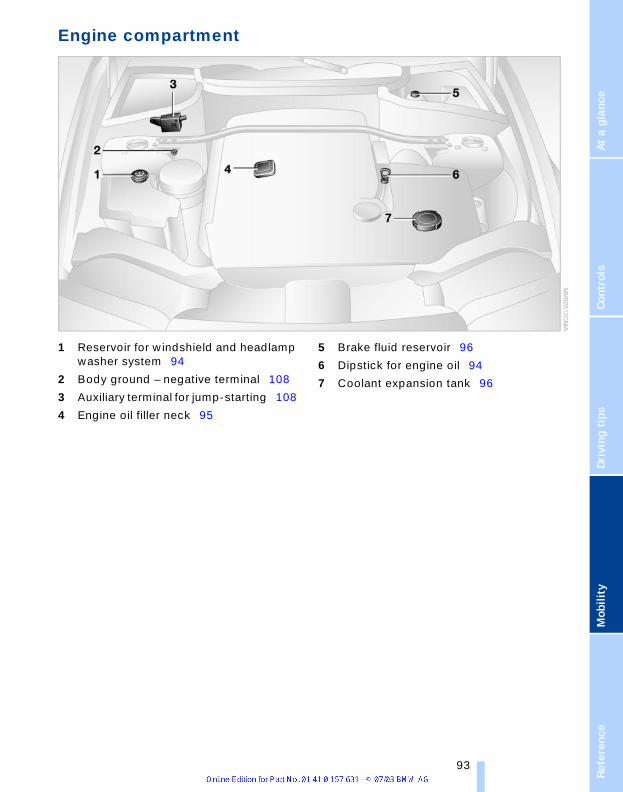
renc
eAt
a g
lanc
eCo
ntro
lsDr
ivin
g ti
psM
obili
ty
Engine compartment
1 Reservoir for windshield and headlamp washer system 94
2 Body ground – negative terminal 108
3 Auxiliary terminal for jump-starting 108
4 Engine oil filler neck 95
5 Brake fluid reservoir 96
6 Dipstick for engine oil 94
7 Coolant expansion tank 96
Refe 93

Un
de
r th
e e
ng
ine
ho
od
Washer fluidWindshield and headlamp washer system
Antifreeze agent for the washer sys-tems is inflammable. For this reason,
keep it away from sources of flame and store it only in its original containers. Store it so that it is inaccessible to children. Always observe the instructions for use provided on the containers.<
We recommend that you mix the washer fluid before adding it to the
reservoir.<
Capacity: approx. 6.9 US quarts/6.5 liters.
Fill with water and, if required, with an anti-freeze additive according to manufac-turer's recommendations.
Engine oil
Indicator lamp
Engine oil pressureThe indicator lamp lights up red:Stop the vehicle immediately and switch off the engine. Check the
engine oil level; top up as required. If the oil level is correct: contact the nearest BMW Sports Activity Vehicle Center.
Do not continue driving. The engine could be damaged because of inade-
quate lubrication.<
Engine oil levelThe indicator lamp lights up yellow while driving:The oil level is at the absolute mini-
mum. Add engine oil as soon as possible. Until then, do not drive more than approx. 30 miles/50 km.
The indicator lamp lights up yellow after the engine is switched off:Top up engine oil at the earliest
opportunity – when refueling.
Engine oil sensorThe indicator lamp lights up yellow within 20 seconds after starting the engine:
The oil level sensor is defective. Please have it checked by a BMW Sports Activity Vehicle Center.
Checking oil level
1. Park the vehicle on a level surface
2. Switch the engine off after it has reached normal operating temperature
3. After approx. 5 minutes, pull the dip-stick out and wipe it off with a clean lint-free cloth, paper towel, or similar mate-rial
4. Carefully push the dipstick all the way into the guide tube and pull it out again
5. The oil should extend to between the two marks on the dipstick.
As is the case with fuel economy, the rate at which the engine uses oil is strongly influenced by driving style and operating conditions. The oil quantity between the two marks of the dipstick is approx. 1.1 US quarts/1 liter.
94

renc
eAt
a g
lanc
eCo
ntro
lsDr
ivin
g ti
psM
obili
ty
Do not fill beyond the upper mark on the dipstick. Excess oil can damage the engine.
Adding engine oil
While you should wait until the level has dropped to just above the lower mark before adding oil, you should never allow the oil level to fall below this mark.
BMW engines are designed to oper-ate without additives, and their use
could even lead to damage in some cases. This also applies to the manual transmis-sion, automatic transmission, the differen-tial and the power steering system.<
Recommendation: have the oil change conducted by your BMW Sports Activity Vehicle Center.
Continuous exposure to used oil has caused cancer in laboratory testing.
For this reason, any skin areas that come into contact with oil should be thoroughly washed with soap and water. Always store oils, grease and similar mate-rials so that they are inaccessible to chil-dren. Comply with warning labels and information on containers.<
Always observe all applicable rules and regulations for environmental
protection when disposing of used oil.<
Approved engine oils The quality of the engine oil selected has critical significance for the operation and service life of an engine. Based on exten-sive testing, BMW has approved only cer-tain engine oils.
Use only approved BMW High Perfor-mance Synthetic Oil.
If you are unable to obtain BMW High Per-formance Synthetic Oil, you can add small amounts of another synthetic oil between oil changes. Use only oils with the API SH specification or higher.
Ask your BMW Sports Activity Vehicle Center for details concerning the spe-
cific BMW High Performance Synthetic Oil or synthetic oils which have been approved.<
You can also call BMW of North America at 1-800-831-1117 or visit this website:www.bmwusa.com to obtain this informa-tion.
Viscosity ratingsViscosity is the oil flow rating as defined in SAE classes.
The selection of the correct SAE class depends on the climate conditions in the area where you typically drive your BMW.
Approved oils are in SAE classes 5W-40 and 5W-30.<
> These oils may be used for driving in all ambient temperatures.
Coolant
Indicator lampThe indicator lamp lights up:Coolant level is too low; top up at the earliest opportunity.
Do not add coolant to the cooling sys-tem when the engine is hot. Escaping
coolant can cause burns. Antifreeze and anticorrosion agents are hazardous to health. You should always store them in their original containers and in a location which is inaccessible to chil-dren. Antifreeze and anticorrosion agents are flammable. Therefore, do not pour over hot engine parts, as otherwise they could catch fire and cause burns. Always observe the instructions for use provided on the containers.<
Refe 95

Un
de
r th
e e
ng
ine
ho
od
Checking coolant level and toppingup coolant
Check the coolant level with the engine cold, approx. 687/206:
1. Turn the cap of the expansion tank counterclockwise to allow any accumu-lated pressure to escape, then continue turning to open
2. The coolant level is correct if the upper end of the red float bar is at least at the same height as the top edge of the filler neck, refer to arrow. The bar end may only protrude by a maximum of i in/2 cm, i.e. up to the second mark on the float bar, refer also to sketch beside the filler neck
3. If necessary, add coolant. Slowly add coolant until the correct level is reached – do not overfill.
Always observe all applicable rules and regulations for environmental
protection when disposing of used anti-freeze and anticorrosion agents.<
Brake system
Malfunction
Brake fluidThe warning lamp lights up red despite the handbrake being released: stop immediately.
The brake fluid in the reservoir has fallen to below the minimum level. At the same time, a considerably longer brake pedal travel may be noticeable. Contact the nearest BMW Sports Activity Vehicle Center.
During continued driving increased brake pedal pressure may be neces-
sary, and considerably longer braking dis-tances may result. Please adapt your driv-ing style accordingly.<
Warning lamp for Canadian models.
Brake pads The indicator lamp comes on.The brake pads have reached their minimum pad thickness. See your
BMW Sports Activity Vehicle Center imme-diately to have the pads replaced.
For your own safety: use only brake pads that BMW has released for your
particular vehicle model. As BMW cannot assess the suitability of other brake pads for use on your vehicle, we are unable to assume continued responsibility for the vehicle's operating safety if non-approved pads are installed.<
For additional information on the brake sys-tem, refer to page 77.
96

Refe
renc
eAt
a g
lanc
eCo
ntro
lsDr
ivin
g ti
psM
obili
ty
97
Maintenance
The BMW maintenance system
The BMW maintenance system is designed in such a way that it reliably ensures the road safety and operating reliability of the vehicle – keeping the cost for you as low as possible.
Regular maintenance is not only required for the safety of the vehicle, it also improves the resale value.
Service Interval DisplayThe BMW Maintenance System takes the driving conditions of the vehicle into account when determining service inter-vals:From the point of view of maintenance, 62,000 miles/100,000 km accumulated in short-distance urban driving are not the equivalent of the same distance covered at moderate speeds in long-distance high-way travel.
The BMW maintenance system is divided into engine oil service as well as Inspec-tions I and II.
Determining the maintenance intervals according to the actual loads on the vehi-cle covers every kind of operating situa-tion. However, even those who drive only short distances – significantly less than 6,200 miles/10,000 km annually – should have the engine oil changed at least every 2 years since oil deteriorates over time, regardless of use.
Brake fluid is hygroscopic: it absorbs moisture from the atmosphere over
the course of time. To ensure that the brake system continues to provide safe and reli-able performance, remember to have the brake fluid changed every two years at the latest by a BMW Sports Activity Vehicle Center, also refer to page 46 and to the Service and Warranty Information Booklet for US models or the Warranty and Service Guide Booklet for Canadian models.<
Service and Warranty Information Booklet for US models/Warranty and Service Guide Booklet for Canadian modelsFor detailed information on required main-tenance items and the work involved, please refer to the Service and Warranty Information Booklet for US models or to the Warranty and Service Guide Booklet for Canadian models.
Depending on operating conditions, it may be advisable to have the body checked for damage from rocks or gravel as a precau-tion against corrosion.
BMW recommends that you have your BMW Sports Activity Vehicle
Center perform the maintenance and repair.Check that the maintenance work is recorded in the Service and Warranty Information Booklet for US models or the Warranty and Service Guide Booklet for Canadian models. These entries will serve as proof that the vehicle has received reg-ular maintenance.<
CareFor all information on this subject, refer to the Caring for your vehicle brochure.

Law
s an
d r
eg
ula
tio
ns
98
Laws and regulations
California Proposition 65 WarningCalifornia laws require us to state the fol-lowing warning:
Engine exhaust and a wide variety of automobile components and parts,
including components found in the interior furnishings in a vehicle, contain or emit chemicals known to the State of California to cause cancer and birth defects and reproductive harm. In addition, certain flu-ids contained in vehicles and certain prod-ucts of component wear contain or emit chemicals known to the State of California to cause cancer and birth defects or other reproductive harm. Battery posts, terminals and related accessories contain lead and lead compounds. Wash your hands after handling. Used engine oil contains chemi-cals that have caused cancer in laboratory animals. Always protect your skin by wash-ing thoroughly with soap and water.<
OBD connector
The interface socket for the Onboard Diag-nostic is located on the left of the driver's side at the bottom of the instrument cluster and under a cover. The cover has the let-ters OBD on it.
The most important components for the composition of the emissions can be checked by a device across this interface.
If the Service Engine Soon indicator lamp comes on either continuously or intermittently, this indicates a
fault in the emissions-related electronic systems. Although the vehicle remains operational, you should have the systems checked by your BMW Sports Activity Vehicle Center at the earliest possible opportunity.
The illuminated indicator lamp informs you of the need for service, not that you need to stop the vehicle. However, the systems should be checked by your BMW Sports Activity Vehicle Center at the next opportu-nity.
If the indicator lamp blinks or flashes, this indicates a high level of engine misfire. Reduce speed and contact the nearest BMW Sports Activity Vehicle Center imme-diately. Severe engine misfiring over even a short period of time can seriously damage emission control system components, especially the catalytic converter.
Service Engine Soon indicator lamp for Canadian models.
If the fuel filler cap is not on tight enough, the OBD system can detect
leaking vapor and the indicator lamp will light up. If the fuel filler cap is then tight-ened, the indicator lamp will usually go out after a short period of time.<

renc
eAt
a g
lanc
eCo
ntro
lsDr
ivin
g ti
psM
obili
ty
Replacing components
Onboard tool kit
The onboard tool kit is located in a com-partment on the left under the cargo area.
Replacing wiper blades
Front
1. Move the wiper to a fold-out position, refer to page 42
2. Lift the wiper arm and press the secur-ing spring, refer to arrow
3. Pull the wiper blade off toward the wiper arm
4. Insert the new blade and snap it into place.
Fold the wipers back down onto the windshield before you turn the igni-
tion key to position 1 or 2 again. If you do not, they could be damaged.<
Rear
1. Lift the wiper arm
2. Pull off the wiper blade, refer to arrow
3. Insert a new wiper blade.
Lamps and bulbsThe lamps and bulbs make essential contri-butions to the safety of your vehicle. There-fore, comply fully with the following instruc-tions during bulb replacement. If you are not familiar with the specified procedures, BMW recommends having the replace-ments carried out at your BMW Sports Activity Vehicle Center.
Never touch the glass of new bulbs with your bare fingers, as even minute
amounts of contamination will burn into the bulb's surface and reduce its service life. To install, use a clean cloth, napkin etc. or hold the bulb by its metal socket.<
A replacement bulb set is available from your BMW Sports Activity Vehicle Center.
To prevent short circuits, before working on any electrical system,
equipment or accessory you should always switch it off and disconnect the cable from the battery's negative terminal before start-ing.To avoid possible injury or equipment dam-age when changing bulbs, observe any instructions provided by the bulb manufac-turer.<
Refe 99

Re
pla
cin
g c
om
po
ne
nts
When maintaining the headlamps,please comply with the instructions in the separate Caring for your vehicle bro-chure.<
Halogen low beams H7 bulb, 55 Watts
Always wear gloves and eye protec-tion – the atmosphere within the bulb
is pressurized. Failure to observe this pre-caution can lead to personal injury should the bulb be damaged.<
Driver's side
1. Apply the screwdriver from the on-board tool kit and pull off the lamp cover
Caution when handling the screw-driver, as otherwise personal
injury can occur or the vehicle can be damaged.<
2. Press the bulb holder downward and remove
3. Remove the bulb, mount a new bulb
4. Apply the bulb holder with the lower edge to the bracket and press it in until the lamp base locks in place.
Front passenger side
Before replacing the bulb, remove the res-ervoir for the windshield washing system from the bracket. To do so, loosen the bolt, refer to arrow, and place the reservoir to one side.
Bear in mind that the windshield washing system reservoir is heavy. If
you do not, injuries or damage to the vehi-cle can occur.<
For bulb replacement procedure, refer to Driver's side.
Halogen high beamsH7 bulb, 55 Watts
Always wear gloves and eye protec-tion – the atmosphere within the bulb
is pressurized. Failure to observe this pre-caution can lead to personal injury should the bulb be damaged.<
Driver's side
1. Open the clip and remove the lamp cover
2. Press the bulb holder downward and remove, refer to Low beams
3. Pull off the lamp base; fit a new lamp base
100

renc
eAt
a g
lanc
eCo
ntro
lsDr
ivin
g ti
psM
obili
ty
4. Apply the lamp base with the lower edge to the bracket and press it in until the lamp base locks in place.
Make sure that the cover does not fall into the engine compartment, as oth-
erwise the vehicle can be damaged or other road users can be endangered.<
Front passenger side
Before replacing the bulb, remove the res-ervoir for the windshield washing system from the bracket. To do so, loosen the bolt, refer to arrow, and place the reservoir to one side.
Bear in mind that the windshield washing system reservoir is heavy. If
you do not, injuries or damage to the vehi-cle can occur.<
For bulb replacement procedure, refer to Driver's side.
Xenon lamps* The service life of these bulbs is very long and the probability of a failure is very low, provided that they are not switched on and off an unusual number of times. If one of these bulbs should nevertheless fail, it is possible to continue driving with great cau-tion using the fog lamps, provided traffic laws in your area do not prohibit this.
To avoid risk of potentially fatal inju-ries: owing to the extremely high volt-
ages at which these units operate, service work should always be entrusted to quali-fied personnel.<
Parking and standing lamps5 Watt bulb
In case of a defect, please contact your BMW Sports Activity Vehicle Center.
Turn signal indicator, front
21 Watt bulb
Access to the turn signal indicator is at the edge of the lamp unit, refer to arrow.
Make sure that the lamp base does not fall into the engine compartment,
as otherwise the vehicle can be damaged or other road users can be endangered.<
1. Turn the lamp base and remove it
2. Replace the bulb
3. Insert the lamp base. If it does not snap in place immediately, turn the lamp base until it does.
Side-mounted turn signal indicators
5 Watt bulb
1. Use finger pressure against the rear end of the lamp, refer to arrow, to press it forward for removal
2. Apply gentle pressure to the bulb while turning it to the left and pull it out
3. Install in the opposite order.
Refe 101

Re
pla
cin
g c
om
po
ne
nts
Front fog lampsH11 bulb, 55 Watts
Always wear gloves and eye protec-tion – the atmosphere within the bulb
is pressurized. Failure to observe this pre-caution can lead to personal injury should the bulb be damaged.<
1. Pull the cover in front of the fog lamp forward
2. Loosen the screws, refer to arrow, and pull out the headlamp
3. Turn the lamp base at the back of the headlamp to the left and remove it
4. Replace the bulb.
Tail lamps
21 Watt bulb
1 Turn signal indicator
2 Backup lamps
3 Rear lamp
4 Rear lamp/brake lamp
Replacing tail lamps
1. Open the flap in the side panel, refer to page 72
2. Lift the side panel if necessary
3. To release the plug-in connection of the cable, press the spring, refer to arrow 1
4. To remove the back panel of the lamp, release the retainer, refer to arrow 2
5. Apply gentle pressure to the bulb fitting while turning it to the left for removal and replacement
6. Install in the opposite order.
Lamps in the tailgate are defective: Please contact your BMW Sports Activity Vehicle Center.
License plate lamp
10 Watt bulb
1. Press the lamp out to the side with a screwdriver
2. Remove the lamp and replace the bulb.
102
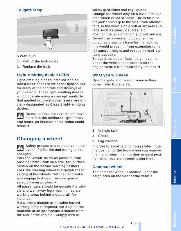
renc
eAt
a g
lanc
eCo
ntro
lsDr
ivin
g ti
psM
obili
ty
Tailgate lamp
5 Watt bulb
1. Pull off the bulb holder
2. Replace the bulb.
Light-emitting diodes LEDsLight-emitting diodes installed behind translucent lenses serve as the light source for many of the controls and displays in your vehicle. These light-emitting diodes, which operate using a concept similar to that applied in conventional lasers, are offi-cially designated as Class 1 light-emitting diodes.
Do not remove the covers, and never stare into the unfiltered light for sev-
eral hours, as irritation of the retina could result.<
Changing a wheel Safety precautions to observe in the event of a flat tire and during all tire
changes:Park the vehicle as far as possible from passing traffic. Park on a firm, flat, surface. Switch on the hazard warning flashers.Lock the steering wheel in straight-ahead setting of the wheels. Set the handbrake and engage first gear, reverse gear or selector-lever position P.All passengers should be outside the vehi-cle and well away from your immediate working area, behind a guardrail, for instance.If a warning triangle or portable hazard warning lamp is required, set it up on the roadside at an appropriate distance from the rear of the vehicle. Comply with all
safety guidelines and regulations.Change the wheel only on a level, firm sur-face which is not slippery. The vehicle or the jack could slip to the side if you attempt to raise the vehicle on a soft or slippery sur-face such as snow, ice, tiles, etc. Position the jack on a firm support surface.Do not use a wooden block or similar object as a support base for the jack, as this would prevent it from extending to its full support height and reduce its load-car-rying capacity.To avoid serious or fatal injury: never lie under the vehicle, and never start the engine while it is supported by the jack.<
What you will need Open tailgate and raise or remove floor cover, refer to page 72.
1 Vehicle jack
2 Chock
3 Lug wrench
In order to avoid rattling noises later, note the position of the tools when you remove them and return them to their original posi-tion when you are through using them.
Compact wheelThe compact wheel is located under the cargo area on the floor of the vehicle.
Refe 103

Re
pla
cin
g c
om
po
ne
nts
1. Unscrew bolt, refer to arrow 1
2. Fold up lifting handle, refer to arrow 2
3. Turn the handle to the left as far as pos-sible, refer to arrow 3
Turning the handle releases the compact wheel. Weight approx.
18 lbs/8 kg. It must be held with the handle.<
4. Slowly lower the handle as far as possi-ble, refer to arrow 4
5. Take out the compact wheel towards the back
6. Refit the compact wheel holder in reverse order.
The defective wheel cannot be fitted in the compact wheel holder in place
of the compact wheel.<
Preparing wheel changeObserve the safety precautions on page 103.<
1. Secure the vehicle to prevent it from rolling:Place the wheel chock against the rear surface of the front tire on the side opposite the side being raised. If the vehicle is parked on a downward slope, place the wheel chock securely in front of the tire. If the wheel must be changed on a surface with a more severe slope, take additional precautions to secure the vehicle from rolling
2. Loosen the lug bolts by a g turn.
Jacking up vehicle
1. Position the vehicle jack at the jacking point closest to the wheel so that the entire surface of the jack base perpen-dicularly contacts the ground under the jacking point
2. Guide the jack head into the rectangular recess of the jacking point when crank-ing up, refer to section of illustration
3. Jack the vehicle up until the wheel you are changing is raised from the ground.
104

renc
eAt
a g
lanc
eCo
ntro
lsDr
ivin
g ti
psM
obili
ty
Mounting compact wheel1. Unscrew the lug bolts and remove the
wheel
2. Remove accumulations of mud or dirt from the mounting surfaces of the wheel and hub. Clean the lug bolts
3. Position the new wheel or compact wheel. Secure the wheel by turning at least two lug bolts into opposite bolt holes
4. Screw in the remaining lug bolts. Tighten all the bolts securely in a diag-onal pattern
5. Lower the jack and remove it from beneath the vehicle
6. Tighten the lug bolts in a diagonal pat-tern
7. Check and correct the tire inflation pressure at the earliest opportunity.
Protect valve stems and valve stem seal caps against dirt and contamina-
tion. Dirt in valve stems is a frequent source of gradual air loss.<
After mounting the compact wheel or cor-recting the inflation pressure, reinitialize the Flat Tire Monitor, refer to page 53.
The vehicle jack is designed for changing wheels only. Do not attempt
to raise another vehicle model with it or to raise any load of any kind. To do so could cause accidents and personal injury.To ensure safety, always have the lug bolts checked with a calibrated torque wrench to ensure that they are tightened to the spec-ified torque of 101 lb ft/140 Nm as soon as possible.<
Stow the defective wheel in the luggage compartment.
When you mount wheels other than Genu-ine BMW light-alloy wheels, different lug bolts may also be required.
Replace the defective tire as soon as pos-sible and have the new wheel/tire bal-anced.
Driving with the compact wheelDrive reservedly and do not exceed a speed of 50 mph/80 km/h. Do not
deactivate DSC, as otherwise unstable driving conditions may result.<
The driving characteristics change, for example reduced track stability on braking, extended braking distance, and altered self-steering characteristics in the limit range. In conjunction with winter tires, these characteristics are more pro-nounced.
Only one compact wheel may be mounted. You should re-equipping to
wheels and tires of the original size as quickly as possible.<
Battery
Battery careThe battery is 100% maintenance-free, i.e., the electrolyte will last for the life of the bat-tery when the vehicle is operated in a tem-perate climate.
Please contact your BMW Sports Activity Vehicle Center with any ques-
tions concerning the battery.<
Do not disconnect the battery when the engine is running. If you do so, the
ensuing voltage surge will damage the vehicle's onboard electronics.<
Indicator lampThe battery charge-current indica-tor lamp lights up:The battery is no longer being
charged. There is a defect on the alternator V-belt or charge current circuit of the alter-nator. Contact the nearest BMW Sports Activity Vehicle Center.
Do not continue driving if the V-belt is defective. The engine could be dam-
aged due to overheating. Moreover, an increased amount of force is required for steering if the onboard supply voltage falls dramatically.<
Refe 105

Re
pla
cin
g c
om
po
ne
nts
Charging the batteryCharge the battery in the vehicle only when the engine is not running. Use the connec-tions provided in the engine compartment. For correct connections, refer to Jump-starting on page 108.
DisposalBring old batteries to a collection point or your BMW Sports Activity
Vehicle Center. Maintain the battery in an upright position for transport and storage. Always restrain the battery to prevent it from tipping over during transport.<
FusesNever attempt to repair a blown fuse, and do not replace a defective fuse
with a substitute of another color or amper-age rating, as this could lead to a circuit overload, ultimately resulting in a fire in the vehicle.<
Open the glove compartment and turn the two quick-release fasteners to the left, refer to arrows.
Spare fuses, plastic tweezers and details of the fuse assignment are located in the compartment for the onboard tool kit.
106

renc
eAt
a g
lanc
eCo
ntro
lsDr
ivin
g ti
psM
obili
ty
Giving and receiving assistance
Receiving assistanceThe Roadside Assistance of the BMW Group offers you assistance in the event of a breakdown around the clock, also at weekends and on public holidays.
The phone numbers of the Roadside Assis-tance control center in your home country can be found in the BMW Dealer Directory.
In the case of vehicles with the corre-sponding equipment, you can use buttons in the headlining to contact Roadside Assistance or start an emergency call.
When an emergency call is started, a tele-phone connection is set up to the general emergency call center.
In vehicles where BMW Assist is enabled, the phone system will also automatically establish contact with the BMW Assist emergency call center. If the current loca-tion of your vehicle can be determined, this is transferred to the BMW Assist emer-gency call center.
The condition for starting an emergency call or contacting Roadside Assistance:
> The car phone is logged on to a mobile telephone network
> The emergency call system is operable.
Starting an emergency call*
Press button, refer to arrow, for at least 2 seconds. The indicator lamp above the buttons lights up. As soon as the voice connection to the general emergency number has been set
up, the indicator lamp flashes.If the indicator lamp flashes, but you are unable to hear the emergency call center, you can still be heard by the emergency call center.
For technical reasons, the emergency call cannot be guaranteed under
unfavorable conditions.<
Under certain conditions, an emergency call is started automatically immediately after a severe accident. The automatic emergency call is not affected by the but-ton being pressed.
Roadside Assistance*
Press button, refer to arrow, for at least 2 seconds. The indicator lamp above the buttons lights up. As soon as the voice connection to Roadside Assistance has been set up, the indicator lamp flashes.
On a country-specific basis, with BMW Assist enabled, the current location of your vehicle is determined at the same time.
Refe 107
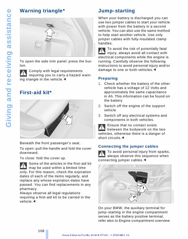
Giv
ing
an
d r
ec
eiv
ing
ass
ista
nc
e
Warning triangle*To open the side trim panel: press the but-ton.
Comply with legal requirements requiring you to carry a hazard warn-
ing triangle in the vehicle.<
First-aid kit*
Beneath the front passenger's seat.
To open: pull the handle and fold the cover downward.
To close: fold the cover up.
Some of the articles in the first-aid kit may be used within a limited time
only. For this reason, check the expiration dates of each of the items regularly, and replace any whose expiration dates have passed. You can find replacements in any pharmacy.Always observe all legal regulations requiring a first-aid kit to be carried in the vehicle.<
Jump-startingWhen your battery is discharged you can use two jumper cables to start your vehicle with power from the battery in a second vehicle. You can also use the same method to help start another vehicle. Use only jumper cables with fully-insulated clamp handles.
To avoid the risk of potentially fatal injury, always avoid all contact with
electrical components while the engine is running. Carefully observe the following instructions to avoid personal injury and/or damage to one or both vehicles.<
Preparing1. Check whether the battery of the other
vehicle has a voltage of 12 Volts and approximately the same capacitance in Ah. This information can be found on the battery
2. Switch off the engine of the support vehicle
3. Switch off any electrical systems and components in both vehicles.
Ensure that no contact exists between the bodywork on the two
vehicles, otherwise there is a danger of short circuits.<
Connecting the jumper cablesTo avoid personal injury from sparks, always observe this sequence when
connecting jumper cables.<
On your BMW, the auxiliary terminal for jump-starting in the engine compartment serves as the battery positive terminal, refer also to Engine compartment overview
108

renc
eAt
a g
lanc
eCo
ntro
lsDr
ivin
g ti
psM
obili
ty
on page 93. The symbol + is embossed on the cover.
1. Open the cover of the BMW auxiliary terminal for jump-starting, refer to arrow 1
2. Connect one terminal clamp of the pos-itive/+ jumper cable to the positive ter-minal of the battery or a auxiliary termi-nal of the vehicle providing starting assistance
3. Connect the second terminal clamp of the positive/+ jumper cable to the posi-tive terminal of the battery or to a auxil-iary terminal of the vehicle to be started. On your BMW, there is a special nut as body ground or negative terminal on the suspension strut dome, refer to arrow 2
4. Attach one end of the jumper cable minus/– to the negative terminal of the battery or to an engine or body ground of the vehicle providing assistance
5. Connect the second terminal clamp of the negative/– jumper cable to the neg-ative terminal of the battery or to the engine or body ground of the vehicle to be started.
Starting the engine1. Start the support vehicle's engine and
let it run at an increased idling speed for a few minutes
2. Start the engine on the other vehicle in the usual way. If the first start attempt is not success-ful, wait a few minutes before another attempt in order to allow the discharged battery to recharge
3. Allow the engines to run for several minutes
4. Disconnect the jumper cables by reversing the connection sequence.
If necessary, have the battery checked and recharged at a BMW Sports Activity Vehi-cle Center.
Never use spray fluids to start the engine.<
TowingAlways observe all applicable towing laws and regulations. Do not tow the
BMW X3 with the axle raised, as otherwise the transfer case can be damaged.<
Towing with a commercial tow truck
> Use only a flatbed carrier
> Do not tow with sling-type equipment
> Do not use a wheel lift.
Never allow passengers to ride on a towed vehicle for any reasons.<
Tow fittingThe threaded tow fitting is stored in the tool kit mounted on the inside of the compart-ment and should always remain in the vehi-cle. This fitting is designed for installation in the tow sockets located at the front and rear of the vehicle.
Access to tow sockets
Front
Use a screwdriver to lever out the cover upward at the recess.
Refe 109

Giv
ing
an
d r
ec
eiv
ing
ass
ista
nc
e
RearUse a screwdriver to lever out the cover upward at the recess.
Only use the tow fitting that comes with the vehicle and screw it in as far
as it will go. Only use the tow fitting to tow on the roadway. Adhere to these specifica-tions, as otherwise the tow fitting can be torn out and damage the vehicle. Never attempt to tow or tie down the vehi-cle using suspension components, as this could lead to damage that might ultimately result in an accident.<
110

renc
eAt
a g
lanc
eCo
ntro
lsDr
ivin
g ti
psM
obili
ty
Refe 111


ReferenceThis is where to look to find
information on any desired topic asquickly as possible.
This chapter includes the sectionwith technical information as well
as the manual's index.

Te
ch
nic
al d
ata
Technical dataEngine specifications
An engine performance test is authorized only on an appropriate chassis dynamometer.
BMW X3 2.5i BMW X3 3.0i
DisplacementNumber of cylinders
cu in/cmm 152.2/2,4946
181.8/2,9796
Maximum outputat engine speed
hprpm
1846,000
2255,900
Maximum torqueat engine speed
lb ft/Nmrpm
175/2373,500
214/2903,500
Compression ratio e 10.5 10.2
StrokeBore
in/mmin/mm
2.95/753.31/84
3.53/89.63.31/84
Fuel-injection system Digital electronic engine-management system DME
114

renc
eAt
a g
lanc
eCo
ntro
lsDr
ivin
g ti
psM
obili
ty
Dimensions
All dimensions in inches/millimeters. Smallest turning circle dia.: 38.4 ft/11.7 m. Height with roof railing*: 66.0 in/1,674 mm.
Refe 115

Te
ch
nic
al d
ata
WeightsNever exceed either the approved axle loads or the gross vehicle weight.
BMW X3 2.5i BMW X3 3.0i
Curb weightwith manual transmissionwith automatic transmission
lbs/kglbs/kg
4,001/1,8154,045/1,835
4,023/1,8254,067/1,845
Approved gross vehicle weightwith manual transmissionwith automatic transmission
lbs/kglbs/kg
4,993/2,2655,049/2,290
5,049/2,2905,104/2,315
Loadwith manual transmissionwith automatic transmission
lbs/kglbs/kg
992/4501,003/455
1,025/4651,036/470
Approved front axle load lbs/kg 2,425/1,100 2,425/1,100
Approved rear axle load lbs/kg 2,756/1,250 2,778/1,260
Approved roof load capacity lbs/kg 165/75 165/75
Cargo area capacity cu ft/l 71/2,010 71/2,010
116

renc
eAt
a g
lanc
eCo
ntro
lsDr
ivin
g ti
psM
obili
ty
Capacities
Notes
Fuel tankReserve
gal./litersgal./liters
approx. 17.7/67approx. 2/8
Fuel specification:page 85
Windshield / Headlamp washer system
quarts/liters approx. 6.9/6.5 For details: page 94
Cooling system including heater quarts/liters 10.6/10.0 formanual
transmission10.8/10.2 for
automatictransmission
For details: page 95
Engine oil and filter change quarts/liters approx. 6.6/6.2 For details: page 94
Manual, automatic transmission and differential
– Lifetime fluid, no fluidchange required
Refe 117

Te
ch
nic
al d
ata
118
ce
Everything from A to Z
Index
A Alarm system 24 Automatic rear window
ceAt
a g
lan
Cont
rols
Driv
ing
tips
Mob
ility
A/C operation– air conditioner 60– automatic climate
control 63ABS Antilock Brake
System 50– indicator lamp 50Accessories 6Activated-charcoal filter 65Adaptive Head Light 57Adding engine oil 95Adjusting seats 27– electric 29– mechanical 28Air, drying, refer to A/C
operation 61, 64Airbags 54– deactivating 34– indicator lamp 55– sitting safely 27Air circulation, refer to
Recirculated-air mode 61, 64
Air conditioner 60, 63Air distribution– air conditioner 61– automatic climate
control 64Airing, refer to
Ventilation 61, 65Air outlets, refer to
Ventilation 61, 65Air pressure, refer to Tire
inflation pressure 86Air supply– air conditioner 61– automatic climate
control 64Air vents, refer to
Ventilation 61, 65AKI, refer to Fuel
specifications 85
– avoiding unintentional alarms 25
Anchorages 73Antifreeze– coolant 95– washer fluid 94Antifreeze protection– coolant 95Anti-theft alarm system 18– refer to Alarm system 24Anti-trapping mechanism– panorama glass roof 24– power windows 22Approved engine oils 95Approved gross vehicle
weight 116Armrest 68– front 68– rear 68Artificial leather, refer to
Caring for your vehicle brochure
Ashtray 69– front 69– rear 69AUC Automatic
recirculated-air control 64
Automatic– air distribution 64– air supply 64Automatic car wash, refer
to Caring for your vehicle brochure
Automatic climate control 63
Automatic cruise control 43Automatic curb monitor 32Automatic headlamp
control 57Automatic program, refer to
automatic air-distribution 64
cleaning 43Automatic recirculated-air
control AUC 64Automatic transmission– malfunction 41Automatic transmission
with Steptronic 39– indicator lamp 41– interlock 37– selector lever interlock 40– shiftlock 40Average fuel
consumption 48Average speed 48Avoiding unintentional
alarms 25Axle load, permitted 116
BBackrests, refer to
Adjusting seats 28Backup lamps 39– replacing bulbs 102Bad roads 80Bar, towing 109Batteries, disposal 106Battery 105– indicator lamp 12, 105– jump-starting 108Belts, refer to Safety
belts 30Beverage holders 67Black ice, refer to Ice
warning 47Blower– air conditioner 61– automatic climate
control 64BMW maintenance
system 97BMW sports seat 28Bore, refer to Engine
data 114
Refe
ren
119

Eve
ryth
ing
fro
m A
to
Z
Bottle holder, refer to Beverage holders 67Brake fluid 96– indicator lamp 96– level 96– replacing 96Brake force display 54Brake lamps– defect 57– indicator lamp 12– replacing the bulbs 102Brake pads and rotors– breaking-in procedure 76Brakes 77, 96– ABS 77– brake fluid 96– break-in procedure 76– handbrake 38– indicator/warning
lamp 38Brake system– brake-fluid level 96– brake pads 96– corrosion 77– disc brakes 76, 77– indicator lamp 96– rotors 76, 77Brake wear warning– brake pads 96– indicator lamp 96Break-in procedures 76Bulbs and lamps 99Buttons in steering
wheel 14
CCalifornia Proposition
65 Warning 98Capacities 117Car care, refer to Caring for
your vehicle brochureCar-care products, refer to
Caring for your vehicle brochure
Care, refer to Caring for your vehicle brochure
120
Cargo area 71– capacity 116– cover 71– floor cover 72– folding rear seat
backrest 71– increasing volume 71– lashing eyes 73– manual unlocking 21– opening, remote
control 19– opening/closing 21– opening from the
outside 21– sockets 73– volume 116Cargo bay, refer to Cargo
area 71Cargo loading 78Caring for leather, refer to
Caring for your vehicle brochure
Caring for the carpet, refer to Caring for your vehicle brochure
Caring for the vehicle finish, refer to Caring for your vehicle brochure
Car keys, refer to Key set 18
Car phone preparation 70Car wash 77Car wash, refer to Caring
for your vehicle brochureCatalytic converter, refer to
High temperatures 76Central locking system 18– interior 20Changes, technical, refer to
For your own safety 6Changing a wheel 103Check Gas Cap– indicator lamp 12, 84Checking inflation
pressure 86Child's seats, refer to
Child-restraint systems 34
Child-restraint systems 34Child-safety locks 36Chock 103
Chrome parts, care, refer to Caring for your vehicle brochure
Cigarette lighter– front 69– rear 69Circulation of air, refer to
Recirculated-air mode 61, 64
Cleaning, vehicle, refer to Caring for your vehicle brochure
Cleaning the windshield 42Cleaning windows,
reservoir 94Clean the rear window 42Clock 46– 12/24 hour mode 48– setting, refer also to
Owner's Manual for Radio/Onboard computer 46
Clutch 76– breaking in 76Cockpit 10Cold start, refer to Starting
the engine 37Comfort operation– panorama glass roof 20Compact wheel– wheel changes 103Compression ratio, refer to
Engine data 114Computer 47Computer, functions 48Condensation, refer to A/C
operation 61, 64Connecting a vacuum
cleaner, refer to Lighter socket 69
Consumption, refer to Average fuelconsumption 48
Consumption indicator, refer to Fuel gauge 45
Contents 3Controls, refer to
Cockpit 10Convenience operation– from outside 20– windows 20

renc
eAt
a g
lanc
eCo
ntro
lsDr
ivin
g ti
psM
obili
ty
Coolant 95– indicator lamp 95– level 96– temperature gauge 45Coolant temperature
gauge 45Cooling, refer to
Temperature 61Copyright 2Cruise control– buttons in steering
wheel 14– indicator lamp 43Cruise control, refer to– Programmable cruise
control 43Cruising range 48Cup holder, refer to
Beverage holders 67Curb weight 116Cylinders, refer to Engine
data 114
DDashboard system, refer to
Cockpit 10Data, technical– dimensions 115– engine 114– filling capacities 117– weights 116Daytime driving lamp 57DBC Dynamic Brake
Control 50– indicator lamp 50Decommissioning the
vehicle, refer to Caring for your vehicle brochure 97
Defect, refer to Manual operation
Defects 7Defrosting, windows 61– air conditioner 62– automatic climate
control 64– rear window
defroster 61, 65
Defrosting windows and removing condensation
– air conditioner 62– automatic climate
control 64Defrosting windshield, refer
to Defrosting windows 62, 64
Defrost position, refer to Defrosting windows 62, 64
Digital clock 46Dimensions 115Dipstick, engine oil 94Directional indicators, refer
to Turn signal indicators 41
Discs brakes 76, 77Displacement, refer to
Engine data 114Display lighting, refer to
Instrument lighting 58Displays, refer to
Instrumentcluster 11
Disposal– batteries 106– oil 95Doors– locking and unlocking 20– manual operation 20DOT Quality Grades 88Draft-free ventilation 61, 65Drawbar support load 116Driving lamps, refer to
Parking lamps/low beams 57
Driving notes 76Driving on bad roads 80Driving stability control
systems 50Driving through water 80DSC Dynamic Stability
Control 50– indicator lamp 51
EElectrical malfunction– door lock 20– doors 20– driver's door 20– fuel filler door 84– panorama glass roof 24– tailgate 21Electric power windows 22Electronic Stability
Program ESP, refer to Dynamic Stability Control 50
Emergency actuation, refer to Manual operation
Emergency call 107Engine– breaking in 76– data 114– indicator lamp 37– malfunction in electronic
circuitry 38– speed 45Engine compartment 93Engine coolant 95Engine hood 92Engine oil 95– indicator/warning
lamp 94– prescribed oils 95Engine oil grades 95Engine oil level 94– indicator/warning
lamp 94Engine oil pressure 94– indicator/warning
lamp 94Engine oil sensor 94– indicator/warning
lamp 94Engine output, refer to
Engine data 114Engine temperature, refer
to Coolanttemperature 45
Equipment range, refer to Service and Warranty Information Booklet for
Refe 121

Eve
ryth
ing
fro
m A
to
Z
US models, Warranty and Service Guide Booklet for Canadian modelsESP Electronic Stability Program, refer to DSC Dynamic Stability Control 50
Exhaust system, refer to High temperatures 76
Exterior mirror– automatic dimming
feature 32Exterior mirrors 31
FFan, refer to Air
supply 61, 64Filling the windshield
washer reservoir 94Filter– refer to Microfilter 62– refer to Microfilter/
Activated charcoal filter 65
First-aid kit 108Fittings, tow-starting and
towing 109Flat tire 103– compact wheel 103– Flat Tire Monitor 53Flat Tire Monitor 53– indicator lamp 53Flooding, refer to Driving on
bad roads 80Floor cover 72Fluid level– indicator lamp 94Fog lamps 58– replacing bulbs 102Folding rear seat back 71Folding rear seat
backrest 71Footbrake, refer to Brake
system 77, 96Footbrake, refer to General
driving notes 77, 96Front/rear reading
lamps 58Front airbags 54Front center armrest 68
122
Front seat adjustment 27Fuel 85– average
fuel consumption 48– capacity 117– gauge 45– quality 85– volume 48Fuel capacity 117Fuel clock, refer to Fuel
gauge 45Fuel display, refer to Fuel
gauge 45Fuel filler cap 84Fuel filler door 84– releasing in the event of
electrical defect 84Fuses 106
GGarage-door opener, refer
to Integrated universal remote control 66
Gasoline, refer to Fuel quality 85
Gasoline consumption, refer to Average fuelconsumption 48
Gasoline display, refer to Fuel gauge 45
Gear changes, refer to Automatic transmission with Steptronic 40
Gear display 41Gear lever– automatic transmission
with Steptronic 39– manual transmission 39General driving notes 76Glove compartment 68Grills, refer to
Ventilation 61, 65Ground clearance 80
HHalogen lamps 100Handbrake– indicator lamp 38
Hands-free microphone, refer to Car phonepreparation 70
Hands-free system 70Hazard warning flashers 10HDC Hill Descent
Control 51Headlamp control,
automatic 57Headlamp flasher 41– indicator lamp 41Headlamps 100– bulb replacement 99Headlamps, care, refer to
Caring for your vehicle brochure
Headlamp washerreservoir 94
Headlamp washer system 94
– cleaning headlamps 42– tank capacity, refer to
Filling capacities 117– washer fluid 94Head restraints 28Heated mirrors 32Heated rear window– air conditioner 61– automatic climate
control 65Heated seats 30Heated steering wheel 31Heated windshield,
automatic climate control 64
Heating– exterior mirror 32– rear window 61, 65– seats 30– steering wheel 31Heating and
ventilation 60, 63Heavy cargo, refer to Cargo
loading 78Height, refer to
Dimensions 115Height adjustment– seats 28– steering wheel 31

renc
eAt
a g
lanc
eCo
ntro
lsDr
ivin
g ti
psM
obili
ty
High beams– bulb replacement 100– headlamp flasher 58– indicator lamp 12High Performance
Synthetic Oil 95Hill-climbing ability, refer to
Driving on bad roads 80Hill descent assistance,
refer to HDC 51Hill Descent Control
HDC 51Hills 77Holder for beverage
cans 67Horn 10Hydraulic Brake Assistant,
refer to DBC 50Hydroplaning 77
IIce warning 47Ignition 37Ignition key 18Ignition lock 37Imprint 2Indicator/warning lamp– airbags 55– alarm system 25– brake system 96– DSC 51– Flat Tire Monitor 53– fog lamps 58– reserve 45– safety belt warning 30Indicator/warning lamps 12Individual settings, refer to
Vehicle Memory, Key Memory 33
Inflation pressure, tires 86Inflation pressure
monitoring, refer to Flat Tire Monitor 53
Instrument cluster 10, 11Instrument illumination 58Instrument lighting 58Integrated universal remote
control 66Interior lamps 58
Interior mirror– automatic dimming
feature 32Interior motion
sensor 22, 25– switching off 19Interior rearview mirror 32Interlock, refer to Ignition
lock 37Intermittent– operation, wipers 41
JJacking points 104Jumping, refer to Jump-
starting 108Jump-starting 108
KKey Memory 33Keys 18Kickdown 40
LLamps and bulbs 99Lashing eyes, refer to
Securing the load 79Leather care, refer to
Caring for your vehicle brochure
LEDs light-emitting diodes 103
License plate lamp– bulb replacement 102Lifting handle, compact
wheel 104Light-alloy wheels, care,
refer to Caring for your vehicle brochure
Light-emitting diodes LEDs 103
Lighter 69Lighter socket 69Lighting of instruments 58Lighting of the instruments,
refer to Instrument lighting 58
Lights, refer to Parking lamps/low beams 57
Lights on warning 57Load, refer to Loading 78Loading– securing the load 79– stowing cargo 79– vehicle 78Loading area– lid, refer to Tailgate 21Load securing devices 79Locking– from inside 20– from outside 18Locking and unlocking
doors– from inside 20– from outside 18Longlife oils– approved oils 95Low beams 57– automatic 57– bulb replacement 100– indicator lamp 57Low-fuel warning light,
refer to Fuel gauge 45Lug bolts 104Luggage compartment,
refer to Cargo areaLuggage rack, refer to
Roof-mounted luggage rack 79
Lumbar support 29
MMaintenance 97Maintenance system,
BMW 97Malfunction in automatic
transmission system 41Manual operation– doors 20– driver's door 20– fuel filler door 84– glass roof 24– panorama glass roof 24– tailgate 21Manual transmission 39Master keys with remote
control 18
Refe 123

Eve
ryth
ing
fro
m A
to
Z
Maximum axle loads 116Maximum roof weight 116MD operation, refer toOwner's Manual for Radio/Onboard computer
Mechanical seats 28Memory, refer to Seat and
mirror memory 29Memory, refer to Vehicle
Memory, Key Memory 33Microfilter– air conditioner 62– automatic climate
control 65Microphone, refer to Car
phone preparation 70Microphone for
telephone 70Mileage, refer to Engine
data 114Mini-Disc operation, refer
to Owner's Manual for Radio/Onboard computer
Mirror– automatic curb
monitor 32– mirror heating 32– mirror memory, refer to
Seat and mirror memory 29
Mirror dimming feature 32Mirrors 31Mobile Service, refer to
Roadside Assistance 107Modifications, technical 6Multifunction switch– turn signal indicators/
headlamp flasher 41– washer/wiper system 41
NNeck support, refer to Head
restraints 28Next Service
indicator 46, 97Nozzles, refer to
Ventilation 61, 65Nylon rope 109
124
OOBD connector 98Octane number, refer to
Fuel quality 85Odometer 45Oil– approved engine oils 95– dipstick 94Oil change interval, refer to
Next Service indicator 97Oil change interval, refer to
Service ManualOil consumption 94Oil grades 95Oil level 94Oil pressure 94Oil sensor– indicator lamp 94OILSERVICE 46, 97Onboard Diagnostic OBD
interface socket 98Onboard tool kit 99Opening and closing 18– from inside 20– from outside 18– using the door lock 20– using the remote
control 18Operating on bad roads 80Output, refer to Engine
data 114Outside air 61– air conditioner 61– automatic climate
control 64Outside temperature
display– changing unit of
measure 47– in computer 47Overview indicator/warning
lamps 12
PPackage tray, refer to
Cargo area 71
Panorama glass roof 23– comfort operation 20– manual operation 24– protective function 24Park Distance Control
PDC 49Parking– vehicle 38Parking aid, refer to Park
Distance Control PDC 49Parking brake, refer to
Handbrake 38Parking lamps 57– bulb replacement 101Parking lamps/low
beams 57Parking the vehicle 38Particulate filter, refer to
Microfilter 62Partition net 72PDC Park Distance
Control 49Plastic, refer to Caring for
your vehicle brochurePollen, refer to
Microfilter 62Pollen, refer to Microfilter/
Activated charcoal filter 65
Power seat 29Pressure, tires 86Pressure monitoring,
tires 53– Flat Tire Monitor 53Programming settings,
refer to Vehicle Memory, Key Memory 33
Protective function– panorama glass roof 24Puncture– Flat Tire Monitor 53
RRadiator, refer to
Coolant 95Radio, refer to separate
Owner's ManualRadio navigation, refer to
separate Owner's ManualRain sensor 42
renc
eAt
a g
lanc
eCo
ntro
lsDr
ivin
g ti
psM
obili
ty
Range– setting units 47Rear armrest, refer to
Center armrest 68Rear backrests– folding 71Rear center armrest 68Rear fog lamps– bulb replacement 102Rear lamps– bulb replacement 102Rear seat back– folding 71Rearview mirrors– exterior 31Rear window defroster– air conditioner 61– automatic climate
control 65Rear window safety
switch 22Rear window wiper 43Recirculated-air mode– air conditioner 61– automatic climate
control 64Reclining seat 28Refueling 84– fuel filler door 84Remaining distance to next
vehicle service 46Remote control– fault 19– garage-door opener 66– tailgate 19Removing condensation,
windows– air conditioner 62– automatic climate
control 64Replacement fuses 106Replacement of tires– wheel changes 103Replacement tire 103Replacing bulbs, refer to
Lamps and bulbs 99Replacing light bulbs 99Reporting safety defects 7Reservoir, washer
system 94
Restraint systems, refer to Safety belts 30
Reverse 39Reverse gear– automatic transmission
with Steptronic 40– manual transmission 39Rims 90Roadside Assistance 107Roll-up cover, refer to
Cargo area cover 71RON, refer to Fuel
quality 85Roof-mounted luggage
rack 79Rope, refer to Tow-starting
and towing 109Rotating coin holder, refer
to Storage compartments 68
SSafe sitting position with
safety belts 27Safety belts 30– sitting safely 27– warning lamp 30Safety belt tensioners, refer
to Safety belts 27Safety belt warning– indicator lamp 30Safety defects, reporting 7Safety feature– power windows 22Safety systems, refer to
ABS Antilock Brake System 50
Safety systems, refer to DSC Dynamic Stability Control 50
Screwdriver, refer to Onboard tool kit 99
Seat, electric power 29Seat heating 30Seat memory, refer to Seat
and mirror memory 29Securing cargo 79Selector lever, automatic
transmission 40
Selector lever interlock, refer to Shiftlock 40
Service and warranty notes 7
Service Engine Soon 38, 98
Service Interval Display 46, 97
Setting the units 47Setting units 47Shiftlock, changing the
selector-lever positions 40
Side airbags 54Side lamps 57Side tilt 80Side turn signal indicators– bulb replacement 101Sitting safely 27– with airbag 27– with safety belts 27Ski bag 70Smokers' package, refer to
Ashtray 69Sockets 69, 73SOS, refer to Starting an
emergency call 107Spare fuses 106Spare key 18Spare tire, refer to Wheel
changes 103Special oils, refer to
Approved oils 95Special washing
program 42Specified oils 95Speedometer 11Speedometer, refer to
Instrumentcluster 11
Sport program– automatic transmission
with Steptronic 40Sports seat 28Stability control, refer to
DSC Dynamic Stability Control 50
Standing lamps 58Starting, engine 37Starting, refer to Starting
the engine 37
Refe 125
Eve
ryth
ing
fro
m A
to
Z
Starting assistance, refer to Jump-starting 108Starting difficulties– temperature 38Starting-off assistance,
DSC 50Starting the engine 38Startup difficulties– jump-starting 108Status of this Owner's
Manual at time of printing 5
Steering lock 37Steering wheel 10, 14– adjustment 31– lock 37Steering wheel heater 31Steering wheel with
buttons 14Steptronic 39Storage compartments 68Storage package 68Storage package nets 68Storage space, refer to
Cargo area 71Storing seat position, refer
to Seat and mirror memory 29
Storing the seat adjustment 29
Straps, refer to Loading 78Stroke, refer to Engine
data 114Supply reservoir cleaning
systems 94Switches, refer to
Cockpit 10Switching off the engine 38Symbols 4
TTable of contents 3Tachometer 45Tailgate– closing 21– emergency operation 21– opening from the
outside 21– remote control 19
126
Tailgate lamp– bulb replacement 103Tail lamps– bulb replacement 102– indicator lamp 57Tank capacity 117Technical modifications 6Telephone, refer to
separate Owner's ManualTemperature– air conditioner 61– automatic climate
control 64Temperature, tires 88Temperature display– ice warning 47– outside temperature 47– setting the units 47Temperature gauge 45Thigh support
adjustment 28, 29Three-point belt 30Tightening torque 105Tilt alarm sensor 25– switching off 25Tilt function, passenger-
side mirror 32Tire inflation pressures 86Tire pressure monitoring,
refer to Flat Tire Monitor 53
Tires– age 88– break-in procedure 76– changing 89– condition 89– DOT Quality Grades 88– flat 103– inflation pressure 86, 87– replacing 89– storage 90– temperature 88– traction 88– treadwear 88– Uniform Tire Quality
Grading 89– wear indicators, refer to
Tire tread/damage 89– wheel change 103Tools, refer to Onboard tool
kit 99
Torque of lug bolts 105Tow bar 109Tow fittings 109Towing 109Towing the vehicle 109Tow rope 109Tow sockets for tow
fitting 109Tow-starting 109Track width, refer to
Dimensions 115Traction 88Traction control– DSC 50Trailer loads 116Transmission 39– automatic transmission
with Steptronic 39– manual transmission 39Transmission lockout, refer
to P Parking 40Transmission
malfunction 41Transporting children 34Transporting children
safely 34Tread depth, refer to Tire
tread 89Treadwear 88Trip-distance counter, refer
to Trip odometer 45Trip odometer 45Trunk, refer to Cargo
area 71Trunk lid, refer to
Tailgate 21Turning circle, refer to
Dimensions 115Turn signal indicators 41– bulb replacement 101Turn signal indicators, side– bulb replacement 101
UUnderbody protection,
refer to Caring for your vehicle brochure
Uniform Tire Quality Grading 89

renc
eAt
a g
lanc
eCo
ntro
lsDr
ivin
g ti
psM
obili
ty
Units 47– outside temperature 47Universal garage-door
opener, refer to Integrated universal remote control 66
Universal remote control 66
Unlocking– engine hood 92– from inside 21– from outside 19Upholstery care, refer to
Caring for your vehicle brochure
VVacuum cleaner
connection 69Vehicle– battery 105– dimensions 115– loading 78Vehicle battery 105Vehicle jack 103Vehicle Memory 33Ventilation 61, 65– draft-free 61, 65Voice control, refer to
separate Owner's Manual
WWarning and indicator
lamps 12Warning triangle 108Warranty, refer to Service
and Warranty Information Booklet for US models, Warranty and Service Guide Booklet for Canadian models 97
Warranty and service notes 7
Washer fluid 94Washer fluid reservoir, refer
to Windshield/headlamp washer system 94
Weights 116
Wheel/tire combination, refer to Replacingwheels/tires 89
Wheelbase, refer to Dimensions 115
Wheel bolts– wrench 103Wheel changes– compact wheel 103Wheels and tires 90Width, refer to
Dimensions 115Windows 22– convenience operation 20Window wipers– replacing 99Windshield– cleaning 42Windshield washer– washer fluid 94Windshield washer system– washer/wiper system 41Windshield wiper blade
replacement 99Windshield wipers, refer to
Wiper/washer system 41Winter tires– changing 103– condition 89– storage 90Wiper/washer reservoir 94Wiper blade
replacement 99Wiper system 94Working in the engine
compartment 92Wrenches, refer to
Onboard tool kit 99
XxDrive 51Xenon lamps 101– replacing the bulbs 101
Refe 127

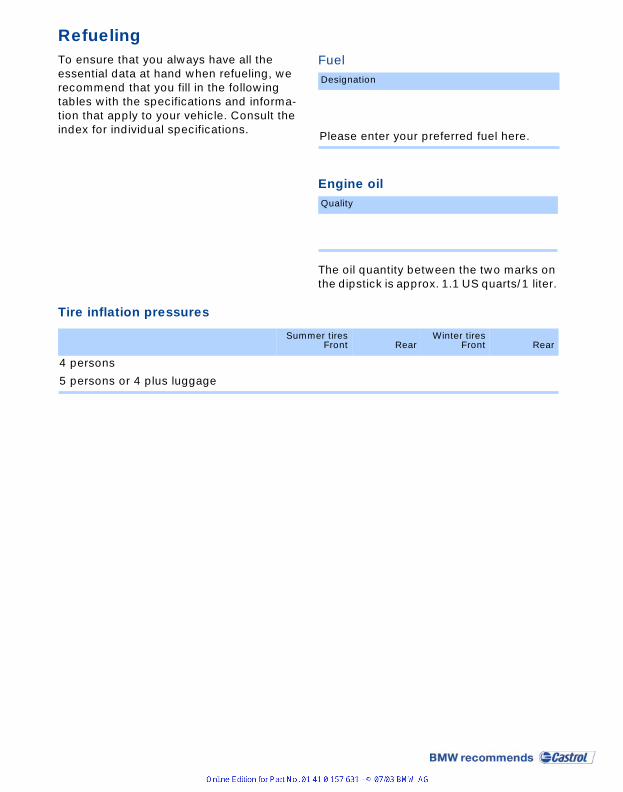
RefuelingTo ensure that you always have all the essential data at hand when refueling, we recommend that you fill in the following tables with the specifications and informa-tion that apply to your vehicle. Consult the index for individual specifications.
Fuel
Engine oil
The oil quantity between the two marks on the dipstick is approx. 1.1 US quarts/1 liter.
Tire inflation pressures
Designation
Please enter your preferred fuel here.
Quality
Summer tiresFront Rear
Winter tiresFront Rear
4 persons
5 persons or 4 plus luggage

01
41
01
57
63
1 u
e
The UltimateDriving Machine
More about BMW
bmwusa.com