OWNER’S MANUAL AND SERVICE GUIDE MANUAL DO PROPRIETÁRIO...
148
STARTING MODEL YEAR: 2004 ANO DE LANÇAMENTO DO MODELO: 2004 OWNER’S MANUAL AND SERVICE GUIDE MANUAL DO PROPRIETÁRIO E GUIA DE MANUTENÇÃO 28806-G01-PT
Transcript of OWNER’S MANUAL AND SERVICE GUIDE MANUAL DO PROPRIETÁRIO...

STARTING MODEL YEAR: 2004ANO DE LANÇAMENTO DO MODELO: 2004
OWNER’S MANUALAND SERVICE GUIDE
MANUAL DO PROPRIETÁRIO E GUIA DE MANUTENÇÃO
28806-G01-PT
GASOLINE POWERED UTILITY VEHICLESVEÍCULOS AGRÍCOLAS A GASOLINA
SAFETY
(NOTES, CAUTIONS AND WARNINGS CONTINUED ON INSIDE OF BACK COVER)
NOTES, CAUTIONS AND WARNINGSThroughout this guide NOTE, CAUTION and WARNINGwill be used.
A NOTE indicates a condition that should beobserved.
A CAUTION indicates a condition thatmay result in damage to the vehicle.
A WARNING indicates ahazardous condition thatcould result in severe
injury or death.
Observe these NOTES, CAUTIONS and WARNINGS;be aware that servicing a vehicle requires mechanicalskill and a regard for conditions that could be hazardous.Improper service or repair may damage the vehicle orrender it unsafe.
Engine exhaust from thisproduct contains chemi-cals known, in certain
quantities, to cause cancer, birth defects, or otherreproductive harm.
The exhaust emissions of this vehicles’ enginecomplies with regulations set forth by the Envi-
ronmental Protection Agency (EPA) of the United States ofAmerica (USA) at time of manufacture. Significant fines couldresult from modifications or tampering with the engine, fuel,ignition or air intake systems.
Battery posts, terminalsand related accessoriescontain lead and lead
compounds. Wash hands after handling.
This spark ignition system meets all require-ments of the Canadian Interference-Causing
Equipment Regulations.
! !�
! !�
! !�
Ce système d'allumage par étincelle de véhicule respectetoutes les exigences du Règlement sur le matériel brouilleurdu Canada.
For any questions on material contained in this manual, contact an authorized representative for clarification.
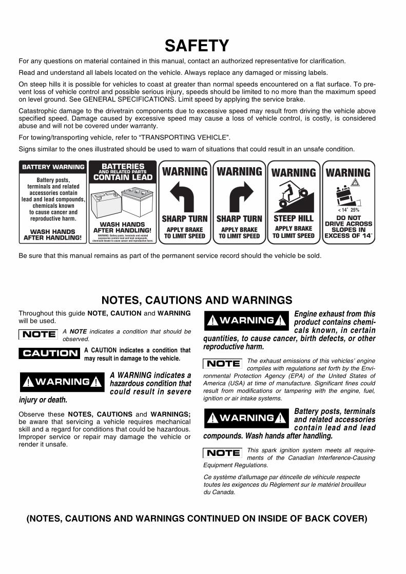
Read and understand all labels located on the vehicle. Always replace any damaged or missing labels.
On steep hills it is possible for vehicles to coast at greater than normal speeds encountered on a flat surface. To pre-vent loss of vehicle control and possible serious injury, speeds should be limited to no more than the maximum speedon level ground. See GENERAL SPECIFICATIONS. Limit speed by applying the service brake.
Catastrophic damage to the drivetrain components due to excessive speed may result from driving the vehicle abovespecified speed. Damage caused by excessive speed may cause a loss of vehicle control, is costly, is consideredabuse and will not be covered under warranty.
For towing/transporting vehicle, refer to “TRANSPORTING VEHICLE”.
Signs similar to the ones illustrated should be used to warn of situations that could result in an unsafe condition.
Be sure that this manual remains as part of the permanent service record should the vehicle be sold.
WASH HANDSAFTER HANDLING!
Battery posts,terminals and relatedaccessories contain
lead and lead compounds,chemicals known
to cause cancer andreproductive harm.
BATTERY WARNING
WASH HANDSAFTER HANDLING!
WARNING: Battery posts, terminals and relatedaccessories contain lead and lead compounds,
chemicals known to cause cancer and reproductive harm.
BATTERIESCONTAIN LEAD
AND RELATED PARTS
!
< 14˚ 25%
DO NOTDRIVE ACROSS
SLOPES INEXCESS OF 14˚

Page iOwner’s Manual and Service Guide
OWNER’S MANUALAND SERVICE GUIDE
GASOLINE POWEREDUTILITY VEHICLES
MPT™ 800
MPT™ 1200
INDUSTRIAL™ 800
INDUSTRIAL™ 1200
E-Z-GO Division of TEXTRON, Inc. reserves the right to make design changes without obligation to make these changes on units previously sold and the infor-mation contained in this manual is subject to change without notice.
E-Z-GO Division of TEXTRON, Inc. is not liable for errors in this manual or for incidental or consequential damages that result from the use of the material in thismanual.
CUSTOMER SERVICE DEPARTMENT IN USA PHONE: 1-800-241-5855 FAX: 1-800-448-8124
OUTSIDE USA PHONE: 010-1-706-798-4311, FAX: 010-1-706-771-4609
E-Z-GO DIVISION OF TEXTRON, INC., P.O.BOX 388, AUGUSTA, GEORGIA USA 30903-0388

Page ii
GENERAL INFORMATION
Owner’s Manual and Service Guide
This vehicle has been designed and manufactured in the United States of America (USA) as a ‘World Vehicle’. The Standards and Specifications listed in the following text originate in
the USA unless otherwise indicated.
The use of non Original Equipment Manufacturer (OEM) approved parts may void the warranty.
Overfilling battery may void the warranty.
Tampering with or adjusting the governor to permit vehicle to operate at above factory specifications will void the vehicle warranty.
When servicing engines, all adjustments and replacement components must be per original vehicle specifications in order to maintain the United States of America Federal and State
emission certification applicable at the time of manufacture.
BATTERY PROLONGED STORAGE
All batteries will self discharge over time. The rate of self discharge varies depending on the ambient temperature and the age and condition of the batteries.
A fully charged battery will not freeze in winter temperatures unless the temperature falls below -75° F (-60° C).

Page iii
TABLE OF CONTENTS
Owner’s Manual and Service Guide
SAFETY ................................................................................................................ inside covers
GENERAL INFORMATION ....................................................................................................... ii
SAFETY INFORMATION ......................................................................................................... vii
BEFORE INITIAL USE .............................................................................................................. 1Fig. 1 Initial Service Chart .........................................................................................................1
CONTROLS AND INDICATORS ............................................................................................... 1KEY/LIGHT SWITCH ...........................................................................................................................................1
Fig. 2 Key/Light Switch, Low Oil Pressure Light and Fuel Gauge ............................................2DIRECTION SELECTOR .....................................................................................................................................2
Fig. 3 Direction Selector ...........................................................................................................2CHOKE ................................................................................................................................................................2FUEL GAUGE ......................................................................................................................................................2LOW OIL PRESSURE INDICATOR LIGHT .........................................................................................................2
Fig. 4 Choke .............................................................................................................................2ACCELERATOR PEDAL .....................................................................................................................................2
Fig. 5 Accelerator and Brake Controls ......................................................................................3COMBINATION BRAKE AND PARK BRAKE PEDAL .........................................................................................3HORN ..................................................................................................................................................................3
Fig. 6 Horn Button .....................................................................................................................3
STEEL LOAD BED .................................................................................................................... 3MANUAL LIFT BED OPERATION .......................................................................................................................4
Fig. 7 Manual Bed Latch ...........................................................................................................4Fig. 8 Bed Prop Rod .................................................................................................................4
ELECTRIC LIFT BED OPERATION ....................................................................................................................4Fig. 9 Electric Lift Switch ...........................................................................................................4
PLASTIC LOAD BED ................................................................................................................ 4MANUAL LIFT BED OPERATION .......................................................................................................................5
Fig. 10 Manual Bed Latch .........................................................................................................5Fig. 11 Gas Strut .......................................................................................................................5
ELECTRIC LIFT BED OPERATION ....................................................................................................................5Fig. 12 Electric Lift Switch .........................................................................................................5
OPERATING THE VEHICLE ..................................................................................................... 6RUN-IN ................................................................................................................................................................6
Fig. 13 Check Oil Level on Dipstick ..........................................................................................6COLD STARTING ................................................................................................................................................6STARTING AND DRIVING ..................................................................................................................................7STARTING THE VEHICLE ON A HILL ................................................................................................................7COASTING ..........................................................................................................................................................7FUEL ....................................................................................................................................................................7BATTERY ............................................................................................................................................................8
Fig. 14 Fueling ..........................................................................................................................8LABELS AND PICTOGRAMS .............................................................................................................................8SUN TOP AND WINDSHIELD .............................................................................................................................812 VOLT POWER OUTLET .................................................................................................................................8
Fig. 15 12 Volt Power Outlet .....................................................................................................8TOWING A TRAILER ..........................................................................................................................................8
VEHICLE CLEANING AND CARE ............................................................................................ 9VEHICLE CLEANING ..........................................................................................................................................9VEHICLE CARE PRODUCTS .............................................................................................................................9
REPAIR ...................................................................................................................................... 9LIFTING THE VEHICLE ......................................................................................................................................9WHEELS AND TIRES .......................................................................................................................................10
Fig. 16 Lifting the Vehicle .......................................................................................................10LIGHT BULB REPLACEMENT ..........................................................................................................................11
Fig. 17 Wheel Installation .......................................................................................................11Fig. 18 Headlight and Turn Signal Bulb Replacement ............................................................11

Page iv Owner’s Manual and Service Guide
TABLE OF CONTENTS
FUSE REPLACEMENT .................................................................................................................................... 11Fig. 19 Tail and Brake Light Bulb Replacement ..................................................................... 12
VEHICLE WITH A DISCHARGED BATTERY ................................................................................................... 12
TRANSPORTING VEHICLE ....................................................................................................12TOWING ........................................................................................................................................................... 12NEUTRAL LOCK .............................................................................................................................................. 12
Fig. 20 Neutral Lock ............................................................................................................... 12HAULING .......................................................................................................................................................... 12
SERVICE AND MAINTENANCE ..............................................................................................13SERIAL NUMBER LABEL LOCATION ............................................................................................................. 13PERIODIC SERVICE SCHEDULE .................................................................................................................. 14
Fig. 21 Periodic Service Schedule ......................................................................................... 14TIRE INSPECTION ........................................................................................................................................... 16CHECKING THE OIL LEVEL ............................................................................................................................ 16
Fig. 22 Clean Entire Dipstick .................................................................................................. 16Fig. 23 Check Oil Level on Dipstick ....................................................................................... 16
CHANGING THE OIL ........................................................................................................................................ 16Fig. 24 Oil Viscosity Chart ...................................................................................................... 17Fig. 25 Clean Top of Engine .................................................................................................. 17Fig. 26 Remove Oil Filter ....................................................................................................... 17Fig. 27 Clean Oil Filter ........................................................................................................... 17Fig. 28 Blowing Out Oil Filter ................................................................................................. 17Fig. 29 Add Engine Oil ........................................................................................................... 18
STARTER/GENERATOR BELT TENSION ....................................................................................................... 18Fig. 30 Checking Belt Tension with Gauge ............................................................................ 18Fig. 31 Checking Belt Tension Manually ................................................................................ 18Fig. 32 Adjusting Belt Tension ............................................................................................... 19
BATTERY CLEANING ...................................................................................................................................... 19Fig. 33 Preparing Acid Neutralizing Solution .......................................................................... 19
BRAKES .......................................................................................................................................................... 19Fig. 34 Typical Brake Performance Test ................................................................................ 20
AIR INTAKE AND COOLING FINS ................................................................................................................... 21Fig. 35 Cleaning Air Intake ..................................................................................................... 21Fig. 36 Cleaning the Cooling Fins .......................................................................................... 21
REAR AXLE ...................................................................................................................................................... 21Fig. 37 Add, Check and Drain Rear Axle Lubricant ............................................................... 21
AIR CLEANER INSPECTION AND REPLACEMENT ....................................................................................... 21Fig. 38 Air Cleaner ................................................................................................................. 22Fig. 39 Canister Type Air Cleaner .......................................................................................... 22
LUBRICATION .................................................................................................................................................. 22Fig. 40 Lubrication Points ....................................................................................................... 22
SPARK PLUGS ................................................................................................................................................. 22PROLONGED STORAGE ................................................................................................................................ 23HARDWARE ..................................................................................................................................................... 23CAPACITIES AND REPLACEMENT PARTS .................................................................................................. 25
Fig. 42 Torque Specifications ................................................................................................. 24Fig. 43 Capacities and Replacement Parts ............................................................................ 25
GENERAL SPECIFICATIONS..................................................................................................27MPT™ 800.......................................................................................................................................................... 28MPT™ 1200........................................................................................................................................................ 29INDUSTRIAL™ 800............................................................................................................................................ 30INDUSTRIAL™ 1200.......................................................................................................................................... 31
Fig. 44 Vehicle Dimensions..................................................................................................... 32Fig. 45 Vehicle Dimensions, Incline Specifications and Turning Clearance Diameter............ 33
VEHICLE WARRANTIES.......................................................................................................... 35DOMESTIC WARRANTY .................................................................................................................................. 36INTERNATIONAL WARRANTY (2004) ............................................................................................................. 37FEDERAL EMISSION COMPONENT DEFECT WARRANTY........................................................................... 39CALIFORNIA EMISSION CONTROL WARRANTY STATEMENT.................................................................... 41

Page v
TABLE OF CONTENTS
Owner’s Manual and Service Guide
DECLARATION OF CONFORMITY (EUROPE ONLY)............................................................ 45
LABELS AND PICTOGRAMS.................................................................................. Appendix A

Page vi Owner’s Manual and Service Guide
TABLE OF CONTENTS

Owner’s Manual and Service Guide
SAFETY INFORMATION
Page vii
This manual has been designed to assist in maintaining the vehicle in accordance with procedures developed by themanufacturer. Adherence to these procedures and troubleshooting tips will ensure the best possible service from theproduct. To reduce the chance of personal injury or property damage, the following must be carefully observed:
GENERAL
Many vehicles are used for a variety of tasks beyond the original intended use of the vehicle; therefore, it is impossibleto anticipate and warn against every possible combination of circumstances that may occur. No warnings can take theplace of good common sense and prudent driving practices.
Good common sense and prudent driving practices do more to prevent accidents and injury than all of the warningsand instructions combined. The manufacturer strongly suggests that all users and maintenance personnel read thisentire manual paying particular attention to the CAUTIONS and WARNINGS contained therein.
If you have any questions regarding this vehicle, contact your closest representative or write to the address on theback cover of this publication, Attention: Product Service Department.
The manufacturer reserves the right to make design changes without obligation to make these changes on units previ-ously sold and the information contained in this manual is subject to change without notice.
The manufacturer is not liable for errors in this manual or for incidental or consequential damages that result from theuse of the material in this manual.
This vehicle conforms to the current applicable standard(s) for safety and performance requirements.
These vehicles are designed and manufactured for off-road use. They do not conform to Federal Motor Vehicle SafetyStandards of the United States of America (USA) and are not equipped for operation on public streets. Some commu-nities may permit these vehicles to be operated on their streets on a limited basis and in accordance with local ordi-nances.
Refer to GENERAL SPECIFICATIONS for vehicle seating capacity.
Never modify the vehicle in any way that will alter the weight distribution of the vehicle, decrease its stabilityor increase the speed beyond the factory specification. Such modifications can cause serious personal injuryor death. Modifications that increase the speed and/or weight of the vehicle will extend the stopping distance and mayreduce the stability of the vehicle. Do not make any such modifications or changes. The manufacturer prohibits anddisclaims responsibility for any such modifications or any other alteration which would adversely affect the safety of thevehicle.
Vehicles that are capable of higher speeds must limit their speed to no more than the speed of other vehicles whenused in a golf course environment. Additionally, speed should be further moderated by the environmental conditions,terrain and common sense.
GENERAL OPERATION
Always:
• Use the vehicle in a responsible manner and maintain the vehicle in safe operating condition.
• Read and observe all warnings and operation instruction labels affixed to the vehicle.
• Follow all safety rules established in the area where the vehicle is being operated.
• Reduce speed to compensate for poor terrain or conditions.

Owner’s Manual and Service Guide
SAFETY INFORMATION
Page viii
• Apply service brake to control speed on steep grades.
• Maintain adequate distance between vehicles.
• Reduce speed in wet areas.
• Use extreme caution when approaching sharp or blind turns.
• Use extreme caution when driving over loose terrain.
• Use extreme caution in areas where pedestrians are present.
MAINTENANCE
Always:
• Maintain the vehicle in accordance with the manufacturer’s periodic service schedule.
• Ensure that repairs are performed by those that are trained and qualified to do so.
• Follow the manufacturer’s maintenance procedures for the vehicle. Be sure to disable the vehicle before performingany maintenance. Disabling includes removing the key from the key switch and removal of a battery wire.
• Insulate any tools used within the battery area in order to prevent sparks or battery explosion caused by shorting thebattery terminals or associated wiring. Remove the battery or cover exposed terminals with an insulating material.
• Use specified replacement parts. Never use replacement parts of lesser quality.
• Use recommended tools.
• Determine that tools and procedures not specifically recommended by the manufacturer will not compromise thesafety of personnel nor jeopardize the safe operation of the vehicle.
• Support the vehicle using wheel chocks and jack stands. Never get under a vehicle that is supported by a jack. Liftthe vehicle in accordance with the manufacturer’s instructions.
• Empty the fuel tank or plug fuel hoses to prevent fuel leakage.
• Maintain the vehicle in an area away from exposed flame or persons who are smoking.
• Be aware that a vehicle that is not performing as designed is a potential hazard and must not be operated.
• Test drive the vehicle after any repairs or maintenance. All tests must be conducted in a safe area that is free of bothvehicular and pedestrian traffic.
• Replace damaged or missing warning, caution or information labels.
• Keep complete records of the maintenance history of the vehicle.
The manufacturer cannot anticipate all situations, therefore people attempting to maintain or repair the vehicle musthave the skill and experience to recognize and protect themselves from potential situations that could result in severepersonal injury or death and damage to the vehicle. Use extreme caution and, if unsure as to the potential for injury,refer the repair or maintenance to a qualified mechanic.
Owner’s Manual and Service Guide
SAFETY INFORMATION
Page ix
VENTILATION
Always store gasoline vehicles in a well ventilated area. Ventilation prevents gasoline fumes from accumulating.
Never fuel a vehicle in an area that is subject to flame or spark. Pay particular attention to natural gas or propane waterheaters and furnaces.
Never work around or operate a vehicle in an environment that does not ventilate exhaust gases from the area. Carbonmonoxide is a dangerous gas that can cause unconsciousness and is potentially lethal.

Owner’s Manual and Service Guide
SAFETY INFORMATION
Page x
Notes:

SAFETY INFORMATION
Page xiOwner’s Manual and Service Guide
Read all of manual to become thoroughly familiar with this vehicle. Pay particular attention to all Notes, Cautions and Warnings
GENERALThe following text is provided as recommended by part IIof American Society of Mechanical Engineers / AmericanNational Standards Institute (ASME/ANSI) B56.8-1988.The manufacturer strongly endorses the contents of thisspecification.
PART IIFOR THE USER
4 GENERAL SAFETY PRACTICES
4.1 Introduction
4.1.1 Like other machines, carriers can cause injuryif improperly used or maintained. Part II contains broadsafety practices applicable to carrier operations. Beforeoperation, the user shall establish such additional spe-cific safety practices as may reasonably be required forsafe operation.
4.2 Stability
4.2.1 Experience has shown that this vehicle, whichcomplies with this standard, is stable when properlyoperated and when operated in accordance with specificsafety rules and practices established to meet actualoperating terrain and conditions. However, improperoperation, faulty maintenance, or poor housekeepingmay contribute to a condition of instability and defeat thepurpose of the standard. Some of the conditions whichmay affect stability are failure of the user to follow safetypractices; also, ground and floor conditions, grade,speed, loading, the operation of the carrier with improperloads, battery weight, dynamic and static forces, and thejudgement exercised by the carrier operator.
(a) The user shall train carrier operators to adherestrictly to the operating instructions stated in this Stan-dard.
(b) The user shall survey specific operating conditionsand environment, and establish and train carrier opera-tors to comply with additional, specific safety practices.
4.3 Nameplates, Markings, Capacity, and Modifica-tions
4.3.1 The user shall maintain in a legible conditionall nameplates, warnings, and instructions which aresupplied by the manufacturer.
4.3.2 The user shall not perform any modification or
addition which affects capacity or safe operation, ormake any change not in accordance with the owner’smanual without the manufacturer’s prior written authori-zation. Where authorized modifications have been made,the user shall ensure that capacity, operation, warning,and maintenance instruction plates, tags, or decals arechanged accordingly.
4.3.3 As required under paras. 4.3.1 or 4.3.2, themanufacturer shall be contacted to secure new name-plates, warnings, or instructions which shall then beaffixed in their proper place on the carrier.
4.4 Fuel Handling and Storage
4.4.1 The user shall supervise the storage and han-dling of liquid fuels (when used) to be certain that it is inaccordance with appropriate paragraphs of AmericanNational Standards Institute/National Fire ProtectionAssociation (ANSI/NFPA) 505 and ANSI/NFPA 30.
4.4.2 Storage and handling of liquefied petroleumgas fuels shall be in accordance with appropriate para-graphs of ANSI/NFPA 505 and ANSI/NFPA 58. If suchstorage or handling is not in compliance with these stan-dards, the user shall prevent the carrier from being useduntil such storage and handling is in compliance withthese standards.
4.5 Changing and Charging Storage Batteries forElectric Personnel and Burden Carriers
4.5.1 The user shall require battery changing andcharging facilities and procedures to be in accordancewith appropriate paragraphs of ANSI/NFPA 505.
4.5.2 The user shall periodically inspect facilitiesand review procedures to be certain that appropriateparagraphs of ANSI/NFPA 505, are strictly compliedwith, and shall familiarize carrier operators with it.
4.6 Hazardous Locations
4.6.1 The user shall determine the hazard classifi-cation of the particular atmosphere or location in whichthe carrier is to be used in accordance with ANSI/NFPA505.
4.6.2 The user shall permit in hazardous areas onlythose carriers approved and of the type required byANSI/NFPA 505.
4.7 Lighting for Operating Areas
4.7.1 The user, in accordance with his responsibilityto survey the environment and operating conditions, shalldetermine if the carrier requires lights and, if so, shall

SAFETY INFORMATION
Page xii Owner’s Manual and Service Guide
Read all of manual to become thoroughly familiar with this vehicle. Pay particular attention to all Notes, Cautions and Warnings
equip the carrier with appropriate lights in accordancewith the manufacturer’s recommendations.
4.8 Control of Noxious Gases and Fumes
4.8.1 When equipment powered by internal com-bustion engines is used in enclosed areas, the atmo-sphere shall be maintained within limits specified in theAmerican Conference of Governmental IndustrialHygienists publication, “Threshold Limit Values forChemical Substances and Physical Agents in the Work-room Environment”. This shall be accomplished by venti-lation provided by the user, and/or the installation, use,and proper maintenance of emission control equipmentrecommended or provided by the manufacturer of theequipment.
4.9 Warning Device(s)
4.9.1 The user shall make periodic inspections ofthe carrier to be certain that the sound-producing and/orvisual device(s) are maintained in good operating condi-tion.
4.9.2 The user shall determine if operating condi-tions require the carrier to be equipped with additionalsound-producing and/or visual devices and be responsi-ble for providing and maintaining such devices, in accor-dance with the manufacturer’s recommendations.
5 OPERATING SAFETY RULES AND PRACTICES
5.1 Personnel and Burden Carrier Operator Qualifications
5.1.1 Only persons who are trained in the properoperation of the carrier shall be authorized to operate thecarrier. Operators shall be qualified as to visual, auditory,physical, and mental ability to safely operate the equip-ment according to Section 5 and all other applicableparts of this Standard.
5.2 Personnel and Burden Carrier Operators’ Training
5.2.1 The user shall conduct an operators’ trainingprogram.
5.2.2 Successful completion of the operators’ train-ing program shall be required by the user before opera-tion of the carrier. The program shall be presented in itsentirety to all new operators and not condensed for thoseclaiming previous experience.
5.2.3 The user should include in the operators’ train-ing program the following:
(a) instructional material provided by the manufac-turer;
(b) emphasis on safety of passengers, material loads,carrier operator, and other employees;
(c) general safety rules contained within this Standardand the additional specific rules determined by the userin accordance with this Standard, and why they were for-mulated;
(d) introduction of equipment, control locations andfunctions, and explanation of how they work when usedproperly and when used improperly, and surface condi-tions, grade, and other conditions of the environment inwhich the carrier is to be operated;
(e) operational performance tests and evaluationsduring, and at completion of, the program.
5.3 Personnel and Burden Carrier Operator Responsibility
5.3.1 Operators shall abide by the following safetyrules and practices in paras. 5.4, 5.5, 5.6, and 5.7.
5.4 General
5.4.1 Safeguard the pedestrians at all times. Do notdrive carrier in a manner that would endanger anyone.
5.4.2 Riding on the carrier by persons other than theoperator is authorized only on personnel seat(s) providedby the manufacturer. All parts of the body shall remainwithin the plan view outline of the carrier.
5.4.3 When a carrier is to be left unattended, stopcarrier, apply the parking brake, stop the engine or turnoff power, turn off the control or ignition circuit, andremove the key if provided. Block the wheels if machineis on an incline.
5.4.4 A carrier is considered unattended when theoperator is 25 ft. (7.6 m) or more from the carrier whichremains in his view, or whenever the operator leaves thecarrier and it is not within his view. When the operator isdismounted and within 25 ft. (7.6 m) of the carrier still inhis view, he still must have controls neutralized, and theparking brake(s) set to prevent movement.
5.4.5 Maintain a safe distance from the edge oframps and platforms.
5.4.6 Use only approved carriers in hazardous loca-tions, as defined in the appropriate safety standards.
5.4.7 Report all accidents involving personnel,

SAFETY INFORMATION
Page xiiiOwner’s Manual and Service Guide
Read all of manual to become thoroughly familiar with this vehicle. Pay particular attention to all Notes, Cautions and Warnings
building structures, and equipment.
5.4.8 Operators shall not add to, or modify, the car-rier.
5.4.9 Carriers shall not be parked or left unattendedsuch that they block or obstruct fire aisles, access tostairways, or fire equipment.
5.5 Traveling
5.5.1 Observe all traffic regulations, including autho-rized speed limits. Under normal traffic conditions keepto the right. Maintain a safe distance, based on speed oftravel, from a carrier or vehicle ahead; and keep the car-rier under control at all times.
5.5.2 Yield the right of way to pedestrians, ambu-lances, fire trucks, or other carriers or vehicles in emer-gency situations.
5.5.3 Do not pass another carrier or vehicle travel-ing in the same direction at intersections, blind spots, orat other dangerous locations.
5.5.4 Keep a clear view of the path of travel,observe other traffic and personnel, and maintain a safeclearance.
5.5.5 Slow down or stop, as conditions dictate, andactivate the sound-producing warning device at crossaisles and when visibility is obstructed at other locations.
5.5.6 Ascend or descend grades slowly.
5.5.7 Avoid turning, if possible, and use extremecaution on grades, ramps, or inclines; normally travelstraight up and down.
5.5.8 Under all travel conditions the carrier shall beoperated at a speed that will permit it to be brought to astop in a safe manner.
5.5.9 Make starts, stops, turns, or direction rever-sals in a smooth manner so as not to shift the load,endanger passengers, or overturn the carrier.
5.5.10 Do not indulge in dangerous activities, such asstunt driving or horseplay.
5.5.11 Slow down when approaching, or on, wet orslippery surfaces.
5.5.12 Do not drive carrier onto any elevator unlessspecifically authorized to do so. Approach elevatorsslowly, and then enter squarely after the elevator car isproperly leveled. Once on the elevator, neutralize thecontrols, shut off power, and set parking brakes. It isadvisable that all other personnel leave the elevatorbefore a carrier is allowed to enter or exit.
5.5.13 Avoid running over loose objects, potholes,and bumps.
5.5.14 To negotiate turns, reduce speed to improvestability, then turn hand steering wheel or tiller in asmooth, sweeping motion.
5.6 Loading
5.6.1 Handle only stable and safely arranged loads.When handling off-center loads which cannot be cen-tered, operate with extra caution.
5.6.2 Handle only loads within the capacity of thecarrier as specified on the nameplate.
5.6.3 Handle loads exceeding the dimensions usedto establish carrier capacity with extra caution. Stabilityand maneuverability may be adversely affected.
5.7 Operator Care of Personnel and Burden Carriers
5.7.1 At the beginning of each shift during which thecarrier will be used, the operator shall check the carriercondition and inspect the tires, warning devices, lights,battery(s), speed and directional controllers, brakes, andsteering mechanism. If the carrier is found to be in needof repair, or in any way unsafe, the matter shall bereported immediately to the designated authority and thecarrier shall not be operated until it has been restored tosafe operating condition.
5.7.2 If during operation the carrier becomes unsafein any way, the matter shall be reported immediately tothe designated authority, and the carrier shall not beoperated until it has been restored to safe operating con-dition.
5.7.3 Do not make repairs or adjustments unlessspecifically authorized to do so.
5.7.4 The engine shall be stopped and the operatorshall leave the carrier while refueling.
5.7.5 Spillage of oil or fuel shall be carefully andcompletely absorbed or evaporated and fuel tank capreplaced before starting engine.
5.7.6 Do not operate a carrier with a leak in the fuelsystem or battery(s).
5.7.7 Do not use open flames for checking electro-lyte level in storage battery(s) or liquid level in fuel tanks.
6 MAINTENANCE PRACTICES
6.1 Introduction

SAFETY INFORMATION
Page xiv Owner’s Manual and Service Guide
Read all of manual to become thoroughly familiar with this vehicle. Pay particular attention to all Notes, Cautions and Warnings
6.1.1 Carriers may become hazardous if mainte-nance is neglected. Therefore, maintenance facilities,trained personnel, and procedures shall be provided.Such facilities may be on or off the premises.
6.2 Maintenance Procedures
6.2.1 Maintenance and inspection of all carriersshall be performed in conformance with the manufac-turer’s recommendations and the following practices.
(a) A scheduled preventive maintenance, lubrication,and inspection system shall be followed.
(b) Only qualified and authorized personnel shall bepermitted to maintain, repair, adjust, and inspect carriers.
(c) Before undertaking maintenance or repair, followthe manufacturer’s recommendations for immobilizingthe carrier.
(d) Block chassis before working underneath it.
(e) Before disconnecting any part of the engine fuelsystem of a gasoline or diesel powered carrier with grav-ity feed fuel systems, be sure shutoff valve is closed, andrun engine until fuel system is depleted and engine stopsrunning.
(f) Before disconnecting any part of the engine fuelsystem of LP gas powered carriers, close the LP gas cyl-inder valve and run the engine until fuel in the system isdepleted and the engine stops running.
(g) Operation to check performance of the carrier shallbe conducted in an authorized area where safe clear-ance exists.
(h) Before commencing operation of the carrier, followthe manufacturer’s instructions and recommended pro-cedures.
(i) Avoid fire hazards and have fire protection equip-ment present in the work area. Do not use an open flameto check level or leakage of fuel, battery electrolyte, orcoolant. Do not use open pans of fuel or flammablecleaning fluids for cleaning parts.
(j) Properly ventilate the work area.
(k) Handle LP gas cylinders with care. Physical dam-age, such as dents, scrapes, or gouges, may danger-ously weaken the tank and make it unsafe for use.
(l) Brakes, steering mechanisms, speed and direc-tional control mechanisms, warning devices, lights, gov-ernors, guards, and safety devices shall be inspectedregularly and maintained in a safe operating condition.
(m) Special carriers or devices designed andapproved for hazardous area operation shall be
inspected to ensure that maintenance preserves the orig-inal approved safe operating features.
(n) Fuel systems shall be checked for leaks and condi-tion of parts. If a leak is found, action shall be taken toprevent the use of the carrier until the leak has beeneliminated.
(o) The carrier manufacturer’s capacity, operation,and maintenance instruction plates, tags, or decals shallbe maintained in legible condition.
(p) Batteries, motors, speed and directional control-lers, limit switches, protective devices, electrical conduc-tors, and connections shall be inspected and maintainedin conformance with manufacturers recommended pro-cedures.
(q) Carriers shall be kept in a clean condition to mini-mize fire hazards and facilitate detection of loose ordefective parts.
(r) Modifications and additions which affect capacityand safe machine operation shall not be performed bythe customer or user without manufacturer’s prior writtenauthorization; where authorized modifications have beenmade, the user shall ensure that capacity, operation,warning, and maintenance instruction plates, tags, ordecals are changed accordingly.
(s) Care shall be taken to ensure that all replacementparts are interchangeable with the original parts and of aquality at least equal to that provided in the originalequipment.
END OF ASME/ANSI B56.8 - 1988 TEXT

OPERATION AND SERVICE INFORMATION
Page 1Owner’s Manual and Service Guide
Read all of manual to become thoroughly familiar with this vehicle. Pay particular attention to all Notes, Cautions and Warnings
Thank you for purchasing this vehicle. Before driving thevehicle, we ask you to spend some time reading thisOwner’s Manual and Service Guide. This guide containsthe information that will assist you in maintaining thishighly reliable vehicle. Some illustrations may showitems that are optional for your vehicle. This guide coversthe operation of several vehicles; therefore, some picto-rial views may not represent your vehicle. Physical differ-ences in controls will be illustrated.
This vehicle has been designed and manufactured as a‘World Vehicle’. Some countries have individual require-ments to comply with their specifications; therefore,some sections may not apply in your country.
Most of the service procedures in this guide can beaccomplished using common automotive hand tools.Contact your service representative on servicing thevehicle in accordance with the Periodic Service Sched-ule.
Service Parts Manuals and Technician’s Repair and Ser-vice Manuals are available from a local Distributor, anauthorized Branch or the Service Parts Department.When ordering parts or requesting information for yourvehicle, provide vehicle model, serial number and manu-facture code.
BEFORE INITIAL USERead, understand and follow the safety label on theinstrument panel. Be sure you understand how to oper-ate the vehicle, its equipment and how to use it safely.Maintaining good performance depends to a large extenton the operator.
Hydrogen gas is generat-ed as a natural part of thelead acid battery charg-
ing process. A 4% concentration of hydrogen gas isexplosive and could cause severe injury or death.Charging must take place in an area that is adequate-ly ventilated (minimum of 5 air exchanges per hour).
To reduce the chance of battery explosion that couldresult in severe injury or death, never smoke aroundor charge batteries in an area that has open flame orelectrical equipment that could cause an electricalarc.
Before a new vehicle is put into operation, the itemsshown in the INITIAL SERVICE CHART must be per-formed (Ref. Fig. 1 on page 1).
Vehicle battery must be fully charged before initial use.
Check for correct tire inflation. See GENERAL SPECIFI-CATIONS.
Check for oil or fuel leaks that could have developed inshipment from the factory.
Determine and record braking distance required to stopvehicle for future brake performance tests.
Remove the protective clear plastic, that protect the seatbottom and back rest during shipping, before placing thevehicle in service.
CONTROLS AND INDICATORSVehicle controls and indicators consist of:
• key/light switch• direction selector• choke• fuel gauge• low oil pressure indicator light• accelerator pedal• combination service and park brake pedal with
front disc brakes (optional)• horn
KEY/LIGHT SWITCHLocated on the dash panel, this switch enables the basicelectrical system of the vehicle to be turned on and off byturning the key. To prevent inadvertent operation of thevehicle when left unattended, the key should be turned tothe ‘OFF’ position and removed (Ref. Fig. 2 on page 2).
If the vehicle is equipped with lights, the key switch has aposition to operate them, indicated by the light icon.
If the vehicle is equipped with factory installedcustom accessories, some accessories remain
operational with the key switch in the ‘OFF’ position.
! !�
Fig. 1 Initial Service Chart
ITEM SERVICE OPERATION
Battery Charge battery
Seats Remove protective plastic covering
Brakes Check operation and adjust if necessary
Check hydraulic brake fluid level if equipped
Establish acceptable stopping distance
Tires Check air pressure (see SPECIFICATIONS)
Fuel Fill tank with correct fuel
Engine Check oil level
Ref Isc 6

OPERATION AND SERVICE INFORMATION
Page 2 Owner’s Manual and Service Guide
Read all of manual to become thoroughly familiar with this vehicle. Pay particular attention to all Notes, Cautions and Warnings
DIRECTION SELECTOR
To reduce the possibility of componentdamage, the vehicle must be complete-
ly stopped before moving the direction selector.
Located on the seat support panel, this lever permits theselection of either ‘F’ (forward) or ‘R’ (reverse) (Ref. Fig.3 on page 2). Vehicle should be left in ‘F’ when unat-tended.
CHOKEThe choke is used to aid cold starting (Ref. Fig. 4 onpage 2). See COLD STARTING section for operatinginstructions.
FUEL GAUGEThe fuel gauge (if equipped) will either be located on thedash panel (electric) (Ref. Fig. 2 on page 2) or directly onthe fuel tank (mechanical).
LOW OIL PRESSURE INDICATOR LIGHTA low oil pressure indicator light is located on the dashpanel (Ref. Fig. 2 on page 2). The light illuminates whenthe oil pressure is low. Check oil level. If oil level isbetween ADD and FULL mark on dipstick, a mechanicalproblem exists within the engine and the vehicle must
not be driven. Contact a local distributor or authorizedbranch.
To prevent engine damage, do not oper-ate engine until oil pressure is correct-
ed. Do not overfill engine. Too much oil may cause smoking orallow oil to enter the air filter enclosure.
If oil level is below ADD mark on dipstick, add oil to bringlevel to FULL mark. Drive vehicle a short distance andcheck oil pressure. If oil light does not come on, continueto use vehicle.
ACCELERATOR PEDAL
Unintentional movementof the accelerator pedalwi l l re lease the park
brake and may cause the vehicle to move which couldresult in severe injury or death.
With the key switch ‘ON’, depressing the acceleratorpedal starts the engine. When the pedal is released, theengine will stop (Ref. Fig. 5 on page 3). To stop the vehi-cle more quickly, depress the service brake.
If key switch is ‘ON’ and park brake is set, depressing theaccelerator inadvertently will release the park brake andwill cause the vehicle to move which could cause severeinjury or death.
Depressing the accelerator pedal will release the parkbrake if it is engaged. This is a feature to assure the vehi-
Fig. 2 Key/Light Switch, Low Oil Pressure Light and Fuel Gauge
Fig. 3 Direction Selector
OFFOFFONON
FUEL
F
E
Low Oil PressureIndicator Light
Key/Light SwitchFuelGauge
Ref Kes 2
ForwardReverse
Ref Dsl 2
Fig. 4 Choke
ChokeRef Chk 1
! !�

OPERATION AND SERVICE INFORMATION
Page 3Owner’s Manual and Service Guide
Read all of manual to become thoroughly familiar with this vehicle. Pay particular attention to all Notes, Cautions and Warnings
cle is not driven with the park brake engaged. Depress-ing the accelerator pedal is not the preferred method ofreleasing the park brake.
Depressing the lower section of the brakepedal is the preferred method of releasing the
park brake to assure the longest service life of brake compo-nents.
COMBINATION SERVICE AND PARK BRAKE PEDALThe brake pedal incorporates a park brake feature (Ref.Fig. 5 on page 3). To engage, push down on the uppersection of the pedal until it locks in place. The park brakewill release when the service brake pedal is depressed.Use the lower section of the brake pedal to operate theservice brake system.
OPTIONAL FRONT DISC BRAKESThe front disc brakes activate as the brake pedalreaches the ‘park’ or ’latch’ position. Depressing thebrake pedal further will increase the effectiveness of thefront brakes.
HORNThe horn is operated by pushing the horn button locatedon the floor to the left of the brake pedal (Ref. Fig. 6 onpage 3).
STEEL LOAD BEDTo reduce the possibilityof severe injury or death,read, understand and fol-
low the Danger label affixed to the front of the loadbed.
The manual lift bed is the standard bed for the vehicle.The bed may be equipped with an optional electric liftswitch.
A load bed warning label is affixed to the front of the bed.See Appendix A. For safe operation of the vehicle, thislabel must be understood. See the load bed warninglabel for maximum load. The load must be positioned inthe bed as far forward as possible, distributed in such away that its center of gravity must not be higher thanheight noted on label, and secured. Failure to followthese instructions may result in severe injury, damagethe vehicle and/or cause the vehicle to tip over. Use extracare when operating loaded vehicle.
Do not permit any one to ride in the bed.
Do not drive the vehicle with the load bed raised or withthe tailgate unsupported.
When using the electric lift, be sure to avoid backing upto the edge of a drop off, such as a loading dock orravine. A misjudgment of distance or an unstable surfacecould result in the vehicle falling backwards.
Before operating load bed, check to ensure no one isbehind the vehicle.
Never fill a gas can in thebed of a vehicle. Staticdischarge could ignite
gasoline vapor and cause an explosion.
Always place a gas can on the ground before filling.Never fill a gas can in the bed of the vehicle. Static elec-tricity is built up during the fueling process and could dis-charge causing the gasoline vapor to ignite.
Fig. 5 Accelerator and Brake Controls
ParkBrake
Accelerator
PARK
ServiceBrake
Ref Abc 1
! !�
Fig. 6 Horn Button
HORN
Horn
PARK
Ref Hor 1
! !�

OPERATION AND SERVICE INFORMATION
Page 4 Owner’s Manual and Service Guide
Read all of manual to become thoroughly familiar with this vehicle. Pay particular attention to all Notes, Cautions and Warnings
MANUAL LIFT BED OPERATION
Exercise caution whileoperating the manual lift.Ensure the bed prop is in
one of the slots before releasing. Severe injury couldresult if bed is released and traps fingers or otherbody parts.
To lift the manual lift bed, pull back on the latch releasehandle immediately behind the driver seat (Ref. Fig. 7 onpage 4). Raise the bed using the handle on the side ofthe bed.
Lift load bed to a secure position and check stabilitybefore releasing bed handle (Ref. Fig. 8 on page 4).
ELECTRIC LIFT BED OPERATION
Exercise caution whileoperating the electric liftbed to ensure clothing is
not snagged during lifting or lowering procedure.
Severe injury could result if bed is lowered and trapsfingers or other body parts.
The electric lift toggle switch is located on the driver’sside of the front seat panel (Ref. Fig. 9 on page 4). Movethe toggle switch upward to raise the dump bed anddownward to lower the dump bed.
PLASTIC LOAD BEDThe manual lift bed is the standard bed for the vehicle.The bed may be equipped with an optional electric liftswitch.
Failure to follow theseinstructions may resultin personal injury, dam-
age the vehicle and/or cause the vehicle to tip over.Operate the vehicle with awareness of the load. Read,understand and follow the Danger label affixed to thefront of the load bed. Do not permit anyone to ride in the bed.Before operating, check to ensure no one is behindthe vehicle.A load bed warning label is affixed to the inside front ofthe bed (see Appendix A). This label must be understoodand observed at all times for safe operation of the vehi-cle. See the load bed warning label for maximum load.The load must be positioned in the bed as far forward aspossible, distributed in such a way that its center of grav-ity must not be higher than height noted on label, andsecurely fastened down. Failure to follow these instruc-tions may result in severe personal injury, damage thevehicle and/or cause the vehicle to tip over. Operate thevehicle with awareness of the load.
Do not permit anyone to ride in the bed.
Do not drive the vehicle with the load bed raised or withthe tailgate unsupported.
When using the electric lift, be sure to avoid backing upto the edge of a drop off, such as a loading dock or
Fig. 7 Manual Bed Latch
Fig. 8 Bed Prop Rod
! !�
Ref Mbl 3
Front of Vehicle
Manual Load Bed LatchMove Rearward to release
Ref Bpr 1
! !�
Fig. 9 Electric Lift Switch
Raise
Lower
Ref Lbs 1
! !�

OPERATION AND SERVICE INFORMATION
Page 5Owner’s Manual and Service Guide
Read all of manual to become thoroughly familiar with this vehicle. Pay particular attention to all Notes, Cautions and Warnings
ravine. A misjudgment of distance or an unstable surfacecould result in the vehicle falling backwards.
Before operating, check to ensure no one is behind thevehicle.
Never fill a gas can in thebed of a vehicle. Staticdischarge could ignite
gasoline vapor and cause an explosion.
Always place a gas can on the ground before filling.Never fill a gas can in the bed of the vehicle. Static elec-tricity is built up during the fueling process and could dis-charge causing the gasoline vapor to ignite.
MANUAL LIFT BED OPERATION
Exercise caution whileoperating the manual liftbed to ensure the bed is
not released during lifting or lowering procedure.Severe injury could result if bed is released and trapsfingers or other body parts.
To lift the manual lift bed, pull back on the latch releasehandle immediately behind the driver seat (Ref. Fig. 10on page 5). Raise the bed using the handle on the side ofthe bed.
The gas strut will assist in raising the empty loadbed andwill keep the bed raised (Ref. Fig. 11 on page 5).
Over time, the gas strut may allow the load bedto slowly lower. If this condition is evident,
replacement of gas strut is required.
To lower the manual lift bed, grasp the bed handle andlower the bed to the rest position. Be sure hands arenot trapped by the bed.
TAIL GATE OPERATIONTo open the tail gate, lift tail gate straight up with a sharpupward pull to lift out of the closed position and pivot outfor open position. To remove the tail gate, remove theside cables from the loadbed and open tail gate until it isstraight down, move tail gate panel straight up to removefrom pins and remove from the load bed. Reassemble inreverse order.
ELECTRIC LIFT BED OPERATION
Exercise caution whileoperating the electric liftbed to ensure clothing is
not snagged during lifting or lowering procedure.Severe injury could result if bed is lowered and trapsfingers or other body parts.
The electric lift toggle switch is located on the driver sideof the front seat panel (Ref. Fig. 12 on page 5). Move thetoggle switch upward to raise the dump bed and down-ward to lower the dump bed.
Fig. 10 Manual Bed Latch
! !�
! !�
Ref Mbl 3
Front of Vehicle
Manual Load Bed LatchMove Rearward to release
Fig. 11 Gas Strut
Fig. 12 Electric Lift Switch
Ref Gss 1
! !�
Raise
Lower
Ref Lbs 1

OPERATION AND SERVICE INFORMATION
Page 6 Owner’s Manual and Service Guide
Read all of manual to become thoroughly familiar with this vehicle. Pay particular attention to all Notes, Cautions and Warnings
OPERATING THE VEHICLEImproper use of the vehicle or the lackof proper maintenance may result in
damage or decreased performance.
Read and understand the following warnings beforeattempting to operate the vehicle.
To reduce the possibilityof severe injury or deathresulting from loss of
vehicle control, the following warnings must beobserved:
When driving vehicle, consider the terrain, trafficconditions and the environmental factors whicheffect the terrain and the ability to control thevehicle.Use extra care and reduced speed when drivingon poor surfaces, such as loose dirt, wet grass,gravel, etc.Stay in designated areas and avoid extremelyrough terrain.Maintain a safe speed when driving down hill. Useservice brake to control speed when travelingdown an incline. A sudden stop or change ofdirection may result in loss of control.Slow down before and during turns. All turnsshould be made at reduced speed.Never drive vehicle up, down, or across an inclinethat exceeds 14° (25% grade).
To reduce the possibilityof severe injury or deathresulting from improper
vehicle operation, the following warnings must beobserved:
Refer to GENERAL SPECIFICATIONS for seatingcapacity.Depressing accelerator pedal will release footoperated park brake and may cause inadvertentvehicle movement. Turn the key to the ‘OFF’ posi-tion whenever the vehicle is parked.To prevent inadvertent movement when the vehi-cle is to be left unattended, engage the parkbrake, move direction selector to forward posi-tion, turn key to ‘OFF’ position and remove key.Make sure that the direction selector is in correctposition before attempting to start the vehicle.
Always bring the vehicle to a complete stopbefore shifting the direction selector.Do not take vehicle out of ‘gear’ while in motion(coast).Check the area behind the vehicle before operat-ing in reverse.All occupants must be seated. Keep entire bodyinside vehicle and hold on while vehicle is inmotion.
RUN-INCheck for oil or fuel leaks that could have developed inshipment from the factory. Avoid full throttle starts andrapid acceleration until the engine has achieved operat-ing temperature.
All engines consume more oil than normal during the firsthours of operation. As internal moving parts are run-in,oil consumption should gradually decrease until the rateof consumption stabilizes.
Check the oil level per the Periodic Service Schedule.Add oil if the level on the dipstick indicates that oil is inthe add oil range (Ref. Fig. 21 on page 14).
Do not overfill engine. Too much oilmay cause smoking or allow oil to enter
the air filter enclosure.
Both the oil dipstick and fill cap must be inplace before operating the engine. Failure to
install the dipstick and fill cap will result in oil becoming contam-inated and/or being discharged into the engine compartment.
The oil should be changed in accordance with the Peri-odic Service Schedule while the engine is warm. SeeSERVICE AND MAINTENANCE for checking oil leveland changing oil procedures.
COLD STARTINGStarting a cold engine may require use of the choke.Depress the accelerator approximately 1" (2.5 cm) oruntil the starter just begins to operate. Pull the choke out
! !�
! !�
Fig. 13 Check Oil Level on Dipstick
Maximum oil levelDO NOT OVERFILL
Safeoperating range
Addoil
Full
Ref Dsk 1

OPERATION AND SERVICE INFORMATION
Page 7Owner’s Manual and Service Guide
Read all of manual to become thoroughly familiar with this vehicle. Pay particular attention to all Notes, Cautions and Warnings
if required. Accelerate slowly and push the choke in com-pletely when the engine runs smoothly.
Do not allow the starter to operate con-tinuously for more than 10 seconds.
Allow 30 seconds between starting attempts. If the vehicle doesnot start on the third attempt, turn the key switch off, set the parkbrake and determine the cause of the problem.
If the vehicle had been running and the engine does notstart within 10 seconds, use the choke.
STARTING AND DRIVING
To reduce the possibilityof roll-back which couldresult in severe injury or
vehicle damage, do not release service brake untilengine has started.
To operate vehicle:• Apply the service brake, place the key in the key
switch and turn it to the ‘ON’ position. • Move the direction selector to the direction
desired.• Release the park brake by depressing the service
brake pedal until the park brake releases. • Slowly depress the accelerator pedal to start the
engine. Release service brake when enginestarts.
• When the accelerator pedal is released, the igni-tion circuit is de-energized and the engine stops.To stop the vehicle more quickly, depress the ser-vice brake pedal.
When the direction selector is in the reverseposition, a warning signal will sound to indicate
that the vehicle is ready to run in reverse.
STARTING THE VEHICLE ON A HILL
To reduce the possibilityof roll-back which couldresult in severe injury or
vehicle damage, do not release service brake untilengine has started.
Do not hold vehicle on hill by usingaccelerator and engine. This will cause
premature and excessive wear to drive train components.
To reduce the possibility of permanent damage to thedrive system, it is important to prevent excessive roll-back when starting the vehicle on a hill.
Place left foot on service brake and release the parkbrake. Depress accelerator with right foot and releasethe service brake by lifting left foot.
COASTING
To reduce the possibilityof severe injury or deathfrom coasting at above
recommended speeds, limit speed with service brake.
On steep hills, it is possible for the vehicle to coast atgreater than normal speeds encountered on a flat sur-face. To reduce the possible loss of vehicle control andsevere drivetrain damage, speeds should be limited to nomore than the maximum governed speed on level ground(see GENERAL SPECIFICATIONS). Limit speed byapplying service brake.
FUEL
To reduce the possibilityof severe injury or deathfrom improper fuel han-
dling:Do not smoke near the fuel tank.Do not refuel near open flame or electrical itemswhich could produce a spark.Always handle gasoline in a well ventilated area.Always wear eye protection to protect againstsplashed fuel and fuel vapors.Always allow adequate space for the expansion ofgasoline. Leave at least 1" (2.5 cm) space belowbottom of filler neck.Inspect fuel cap, tank and other components forleaks or deterioration that could cause a hazard-ous condition.
The fuel tank is located under the seat on the passengerside of the vehicle (Ref. Fig. 14 on page 8). Fill the tankwith fresh, clean, automotive grade gasoline (Ref. Fig. 42on page 25). High altitude or heavy use/load applicationsmay benefit from higher octane gasoline.
Do not use gasoline which contains Methanol.
Some fuels, called oxygenated or reformu-lated gasoline, are gasoline blended with
alcohols or ethers. Excessive amounts of these blends can damage thefuel system or cause performance problems. If any undesirable operat-ing symptoms occur, use gasoline with a lower percentage of alcohol orether.
! !�
! !�
! !�
! !�

OPERATION AND SERVICE INFORMATION
Page 8 Owner’s Manual and Service Guide
Read all of manual to become thoroughly familiar with this vehicle. Pay particular attention to all Notes, Cautions and Warnings
BATTERY
Excessive use of accessories may drainthe battery and leave insufficient
reserve to start the vehicle.
The vehicle uses a combination starter/generator to bothstart the engine and charge the battery. The engine willnot idle; therefore, the battery cannot be charged whilethe vehicle is stopped. Do not operate accessory items(such as accessory lights, radios, winch, etc.) exces-sively while the vehicle is stopped.
The generator is capable of supplying 35 amps; there-fore, operation of all accessories could result in the dis-charge of the battery even though the engine is runningand the generator operating. Discharging the battery isknown as deep cycling. The battery is not a deep cyclemodel, but is a starting battery. Multiple deep cycling willresult in the premature failure of the battery.
If the vehicle battery has become discharged, it must becharged using a 12 volt charger that is rated at 10 ampsor less and in accordance with all instructions providedby the manufacturer of the charger.
LABELS AND PICTOGRAMSVehicles may be labeled with pictograms as a method ofconveying information or warnings. Appendix A illus-trates and explains pictograms that may appear on thevehicle. Not all pictograms shown in Appendix A will befound on your vehicle.
SUN TOP AND WINDSHIELD
The sun top does notprovide protection fromr o l l o v e r o r f a l l i n g
objects.
The windshield does not provide protection from treelimbs or flying objects.
To prevent damage to the vehicle, donot hold on to sun top struts and stand
on body panels.
The sun top and windshield provide some protectionfrom the elements; however, they will not keep the oper-ator and passenger dry in a downpour. This vehicle is notequipped with seat belts and the sun top has not beendesigned to provide roll over protection. In addition, thesun top does not protect against falling objects nor doesthe windshield protect against flying objects and treelimbs. Keep arms and legs inside of vehicle while it ismoving.
12 VOLT POWER OUTLET
Overuse of accessories may drain thebattery and leave insufficient reserve to
start the vehicle.
A 12 volt power outlet, rated at 15 amps, is located to theleft side of the key/light switch (Ref. Fig. 15 on page 8). Itprovides constant power for accessories equipped with a12 volt plug.
TOWING A TRAILERThe vehicle is equipped with a receiver that can be fittedwith a standard 1 7/8" ball. The trailer and its load mustnot exceed 500 lbs (227 kg) and no more than 50 lbs (23kg) tongue weight may be attached to the hitch. Remem-ber that the overall capacity of the vehicle, operator, pas-senger, contents of load bed and accessories must bereduced to compensate for the trailer and load.
The range of motion of the trailer is limited by the ball andhitch. The trailer should not be used on rough trails orover objects such as logs, large rocks, holes, etc.
Never install baskets or extensions using the hitchreceivers (front or rear). Such items will change the per-formance characteristics of vehicle and result in unsafehandling, possible roll over or vehicle damage.
Fig. 14 Fueling
1" Min.(2.5 cm)
Fuel
Ref Ftl 1
! !�
Fig. 15 12 Volt Power Outlet
12V PowerOutlet
ONOFF
FUEL
FE
Ref Pow 1

OPERATION AND SERVICE INFORMATION
Page 9Owner’s Manual and Service Guide
Read all of manual to become thoroughly familiar with this vehicle. Pay particular attention to all Notes, Cautions and Warnings
VEHICLE CLEANING AND CAREVEHICLE CLEANING
To reduce the possibilityof severe injury or vehi-cle damage, read and
understand all instructions supplied by manufacturerof pressure washer.
When pressure washing exterior ofvehicle, do not use pressure in excess
of 700 psi. To reduce the possibility of cosmetic damage, do notuse any abrasive or reactive solvents to clean plastic parts.
It is important that proper techniques and cleaning mate-rials be used. Using excessive water pressure maycause severe injury to operator or bystander, damage toseals, plastics, seat material, body finish or electrical sys-tem. Do not use pressure in excess of 700 psi to washexterior of vehicle.
Clean windshield with lots of water and a clean cloth.Minor scratches may be removed using a commercialplastic polish or Plexus® plastic cleaner available fromthe service parts department.
Normal cleaning of vinyl seats and plastic or rubber trimrequires the use of a mild soap solution applied with asponge or soft brush and wipe with a damp cloth.
Removal of oil, tar, asphalt, shoe polish, etc. will requirethe use of a commercially available vinyl/rubber cleaner.
The painted surfaces of the vehicle provide attractiveappearance and durable protection. Frequent washingwith lukewarm or cold water and mild detergent isrequired to preserve the painted surfaces.
Occasional cleaning and waxing with non-abrasive prod-ucts designed for ‘clear coat’ automotive finishes willenhance the appearance and durability of the paintedsurfaces.
Corrosive materials used as fertilizers or for dust controlcan collect on the underbody of the vehicle. These mate-rials will cause corrosion of underbody parts unlessflushed occasionally with plain water. Thoroughly cleanany areas where mud or other debris can collect. Sedi-ment packed in closed areas should be loosened to easeit’s removal, taking care not to chip or otherwise damagepaint.
If the engine does not start or runs improperlyafter washing, remove the spark plug wires (by
pulling the spark plug boots, never the wires). Dry all connec-tions with forced air. Reinstall the wires.
VEHICLE CARE PRODUCTSTo help maintain the vehicle there are several productsavailable through local Distributors, authorizedBranches, or the Service Parts Department.
• Touch-up paint specially formulated to matchvehicle colors for use on both metal and moldedplastic bodies. (P/N 28140-G** and 28432-G**)
• Battery Protectant formulated to form a long-term,flexible, non-tacky, dry coating that will not crack,peel or flake over a wide temperature range. (P/N75500-G01)
• White Lithium Grease designed to provide lubrica-tion protection in areas where staining or discolor-ing is a problem, or in areas of extremetemperature ranges. (P/N 75502-G01)
• Penetrant/Lubricant, a 4-in-1 product that pene-trates seized parts, lubricates leaving a light lubri-cating film, reduces corrosion by adhering to wetor dry surfaces and displaces moisture, sealingagainst future moisture return. (P/N 75503-G01)
• Multi-purpose Cleaner and Degreaser that con-tains natural, environmentally safe solvents. (P/N75504-G01)
• Multi-purpose Hand Cleaner is an industrialstrength cleaner containing no harsh solvents, yetgently lifts grease off hands. May be used with orwithout water. (P/N 75505-G01)
• Battery Cleaner that neutralizes battery acids anddissolves terminal corrosion and can be rinsedwith water. (P/N 75506-G01)
• Biodegradable Cleaner that breaks down greaseto be easily wiped or rinsed away. (P/N 75507-G01)
• Multi-purpose Value Pack sampler includes 4ounce (118 ml) aerosol cans of Battery Protector,Penetrant/Lubricant, White Lithium Grease, andCarburetor and Choke Cleaner. (P/N 75508-G01)
• Plexus® plastic cleaner and polish removes minorscratches from windshield. (P/N 28433-G**)
REPAIRLIFTING THE VEHICLETool List Qty. Required
Floor jack..................................................................... 1Jack stands ................................................................. 4Chocks ........................................................................ 4
Some servicing operations may require the front wheels,the rear wheels, or the entire vehicle be raised.
! !�

OPERATION AND SERVICE INFORMATION
Page 10 Owner’s Manual and Service Guide
Read all of manual to become thoroughly familiar with this vehicle. Pay particular attention to all Notes, Cautions and Warnings
To reduce the possibilityof severe injury or deathfrom a vehicle fall ing
from a jack:Be sure the vehicle is on a firm and level surface.Never get under a vehicle while it is supported bya jack.Use jack stands and test the stability of the vehi-cle on the stands.Always place chocks in front and behind thewheels not being raised.Use extreme care since the vehicle is extremelyunstable during the lifting process.
When lifting vehicle, position jacks andjack stands at the areas indicated only.
To raise the entire vehicle, install chocks in front andbehind each front wheel (Ref. Fig. 16 on page 10). Cen-ter the jack under the rear frame crossmember. Raisethe vehicle enough to place a jack stand under the outerends of the rear axle.
Lower the jack and test the stability of the vehicle on thetwo jack stands.
Place the jack at the center of the front axle. Raise thevehicle enough to place jack stands under the framecrossmember as indicated.
Lower the jack and test the stability of the vehicle on allfour jack stands.
If only the front or rear of the vehicle is to be raised, placethe chocks in front and behind each wheel not beingraised to stabilize the vehicle.
Lower the vehicle by reversing the lifting sequence.
WHEELS AND TIRES
Tire RepairTool List Qty. Required
Lug wrench, 3/4" ......................................................... 1Impact socket, 3/4", 1/2" drive..................................... 1Impact wrench, 1/2" drive............................................ 1Torque wrench, 1/2" drive ........................................... 1
A t i re explosion cancause severe injury ord eath . Never exceed
inflation pressure rating on tire sidewall.
To reduce the possibility of tire explosion, pres-surize tire with small amount of air applied inter-mittently to seat beads. Due to the low volume ofthe small tires, overinflation can occur in sec-onds. Never exceed the tire manufacturer’s rec-ommendation when seating a bead. Protect faceand eyes from escaping air when removing valvecore.
To reduce the possibility of severe injury causedby a broken socket when removing wheels, useonly sockets designed for impact wrench use.
Use caution when inflating tires. Overinflationcould cause the tire to separate from the wheel orcause the tire to explode, either of which couldcause severe injury.
Use caution when inflating tires. Due to the low volume ofthe small tires, overinflation can occur in seconds. Over-inflation could cause the tire to separate from the wheelor cause the tire to explode.
Tire inflation should be determined by the condition ofthe terrain. See GENERAL SPECIFICATIONS sectionfor recommended tire inflation pressure. For outdoorapplications with major use on grassy areas, the follow-
! !�
! !�
Fig. 16 Lifting the Vehicle
Ref Liv 1 View from Underside of Vehicle
Center ofFront Axle
Flat Portionof Frame
Outside Endof Rear Axle

OPERATION AND SERVICE INFORMATION
Page 11Owner’s Manual and Service Guide
Read all of manual to become thoroughly familiar with this vehicle. Pay particular attention to all Notes, Cautions and Warnings
ing should be considered. On hard turf, it is desirable tohave a slightly higher inflation pressure. On very softturf, a lower pressure reduces the possibility of tires cut-ting into the turf. For vehicles being used on paved orhard surfaces, tire inflation pressure should be in thehigher allowable range, but under no condition shouldinflation pressure be higher than recommended on tiresidewall. All four tires should have the same pressurefor optimum handling characteristics. Be sure to installthe valve dust cap after checking or inflating.
The vehicle is fitted with low pressure tubeless tiresmounted on one piece rims; therefore, the most costeffective way to repair a puncture in the tread is to use acommercial tire plug.
Tire plug tools and plugs are available at mostautomotive parts outlets and have the advan-
tage of not requiring the tire be removed from the wheel.
If the tire is flat, remove the wheel and inflate the tire tothe maximum recommended pressure for the tire.Immerse the tire in water to locate the leak and mark withchalk. Insert tire plug in accordance with manufacturer’sinstructions.
To reduce the possibilityof severe injury, be suremounting/demounting
machine is anchored to floor. Wear OSHA approvedsafety equipment when mounting/demounting tires.
If the tire is to be removed or mounted, the tire changingmachine manufacturer’s recommendations must be fol-lowed in order to reduce possibility of severe injury.
Wheel Installation
To reduce the possibility of componentdamage, do not tighten lug nuts to more
than 85 ft. lbs. (115 Nm) torque.
It is important to follow the ‘cross sequence’pattern when installing lug nuts. This will
assure even seating of the wheel against the hub.
With the valve stem to the outside, mount the wheel ontothe hub with lug nuts. Finger tighten lug nuts in a ‘crosssequence’ pattern (Ref. Fig. 17 on page 11) . Tighten lugnuts to 50 - 85 ft. lbs. (70 - 115 Nm) torque in 20 ft. lbs.(30 Nm) increments following the ‘cross sequence’ pat-tern.
LIGHT BULB REPLACEMENT
To reduce the possibility of prematurebulb failure, do not touch new bulbs
with bare fingers. Use clean, dry tissue or paper towel to handlethe glass portion of the bulb.
For vehicles with headlights mounted in cowl, locate thetwo screws on backside of cowl that secure headlight(Ref. Fig. 18 on page 11). Remove screws, pull headlightout and disconnect wires. Connect wires to new head-light, install in cowl and secure with screws previouslyremoved.
To replace the turn signal light bulb, support turn signalhousing from backside of cowl while removing twoscrews securing lens. Install new bulb and replace lens.
To replace the tail and brake light bulb, roll the rubberbezel from around the edge of the taillight and removelens. Install replacement bulb and replace lens.
FUSE REPLACEMENT
To replace fuses, locate the fuse block under the driverside seat. Pull out old fuse and replace with a new auto-motive type fuse. Headlight and taillight bulbs and fusesare available from a local Distributor, an authorizedBranch or the Service Parts Department.
! !�
Fig. 17 Wheel Installation
Fig. 18 Headlight and Turn Signal Bulb Replacement
Tire stylemay vary
1
2
3
4
'Cross Sequence'
Ref Whi 1
HeadlightBulb
Turn Signal Lens
Turn SignalHousing
Insideof Cowl
Ref Hdr 2

OPERATION AND SERVICE INFORMATION
Page 12 Owner’s Manual and Service Guide
Read all of manual to become thoroughly familiar with this vehicle. Pay particular attention to all Notes, Cautions and Warnings
VEHICLE WITH A DISCHARGED BATTERY
To reduce the possibilityof severe injury or deathfrom inadvertent motion,
do not attempt to ‘jump start’ a vehicle.
The vehicle is equipped with a starter/generator anddoes not idle. When starting the engine, the starter/gen-erator functions as a starter and with the engine running,it functions as a generator.
With the short running times associated with this kind ofvehicle, the generator is more than adequate to maintainthe battery charge level. The generator is not designed tocharge a discharged battery.
When engine starts, the clutches engage and causevehicle to move making ‘jump starting’ both dangerousand impractical.
If the vehicle battery has become discharged, it must becharged using a 12 volt charger that is rated at 10 ampsor less. Read and understand all instructions provided bythe manufacturer of the charger.
TRANSPORTING VEHICLETOWING
T h i s v e h i c le i s n o tdesigned to be towed.
It is recommended that the vehicle be moved by placingthe entire vehicle on a trailer, flatbed truck or other suit-able transport.
NEUTRAL LOCKTo prevent the driven clutch from turning the rear wheelsduring service operations, a neutral lock is located on thedirection selector.
To operate:
Turn key switch to ‘OFF’ and lift seat. Pull out and rotatethe neutral lock pin handle so that the pointed portion ofthe handle is to the side of the direction selector cam(Ref. Fig. 20 on page 12). Move direction selectortowards the area between ‘F’ and ‘R’. During that motion,the pin will snap into the hole in the direction selectormounting bracket preventing any movement. When inthis position, the direction selector remains locked in theneutral position. To unlock the direction selector, pull theneutral lock pin handle out and rotate until the pointedportion of the handle fits into the hole in the directionselector cam.
HAULING
To reduce the possibilityof severe injury or deathwhile transporting vehi-cle:
Secure the vehicle and contents.Never ride on vehicle being transported.Always remove windshield before transporting. Maximum speed with sun top installed is 50 mph(80 kph).
Fig. 19 Tail and Brake Light Bulb Replacement
RearFender
Tail/BrakeLight
Roll RubberBezel AwayFrom Body
Ref Tlr 2
! !�
! !�
Fig. 20 Neutral Lock
Unlocked
ToLock
Hole in DirectionSelector MountingBracket
Hole in DirectionSelector Cam
Neutral LockPin Handle
1
2
Ref Nlk 2
! !�

OPERATION AND SERVICE INFORMATION
Page 13Owner’s Manual and Service Guide
Read all of manual to become thoroughly familiar with this vehicle. Pay particular attention to all Notes, Cautions and Warnings
If the vehicle is to be transported at highway speeds, thesun top must be removed and the seat bottom secured.When transporting vehicle below highway speeds, checkfor tightness of hardware and cracks in sun top at mount-ing points. Always remove windshield when transporting.Always check that the vehicle and contents are ade-quately secured before transporting. The rated capacityof the trailer or truck must exceed the weight of the vehi-cle (see GENERAL SPECIFICATIONS for vehicleweight) and load. Lock the park brake and secure thevehicle using ratchet tie downs.
SERVICE AND MAINTENANCETo reduce the possibilityof severe injury or deathfrom improper servicing
techniques:Do not attempt any type of servicing operationsbefore reading and understanding all notes, cau-tions and warnings in this manual.Any servicing requiring adjustments to be madeto the powertrain while the engine is runningmust be made with both drive wheels raised andvehicle properly supported on jack stands.To reduce the possibility of engine damage, neveroperate vehicle at full throttle for more than 4 - 5seconds while vehicle is in a ‘no load’ condition.
Wear eye protection when working onthe vehicle. Use extra care when work-ing around batteries, or using sol-vents or compressed air.
To reduce the possibility of causing an electricalarc, which could result in a battery explosion, turnoff all electrical loads from the battery beforeremoving battery wires.
Wrap wrenches with vinyltape to reduce the possibilityof a dropped wrench ‘short-
ing out’ a battery, which could result in an explo-sion.Reduce the possibility of accidental starting byremoving and grounding spark plug wires anddisconnecting battery at negative terminal beforeservicing.The electrolyte in a battery is an acid solutionwhich can cause severe burns to the skin andeyes. Treat all electrolyte spills to the body and
eyes with extended flushing with clear water.Contact a physician immediately. Any electrolyte spills should be neutralized with asolution of 2 teaspoons (10 ml) sodium bicarbon-ate (baking soda) dissolved in 1 quart (1 liters) ofwater and flushed with water.Aerosol containers of battery terminal protectantmust be used with extreme care. Insulate metalcontainer to reduce the possibility of can contact-ing battery terminals which could result in anexplosion.
It is in the best interest of both vehicle owner and servicetechnician, to carefully follow the procedures recom-mended in this manual. Preventative maintenance,applied at recommended intervals, is the best guaranteefor keeping the vehicle both dependable and economical.
This vehicle will give years of satisfactory service, provid-ing it receives regular maintenance. Refer to the PeriodicService Schedule for appropriate service intervals (Ref.Fig. 21 on page 14). Refer to Lubrication Points forappropriate lubrication locations (Ref. Fig. 40 on page22).
To prolong vehicle life, some mainte-nance items must be serviced more fre-
quently on vehicles used under severe driving conditions suchas extreme temperatures, extreme dust/debris conditions, fre-quent use with maximum load.
To access powertrain for routine maintenance, lift orremove seat. For major repair, refer to appropriate Tech-nician’s Repair and Service Manual.
Some service procedures may require the vehicle to belifted. Refer to LIFTING THE VEHICLE for proper liftingprocedure and safety information.
SERIAL NUMBER LABEL LOCATIONTwo serial number and manufacture date code label areon the vehicle. One is placed on the body below thefront, driver side of the seat. The other is located on thechassis under the seat.
Design changes take place on an ongoing basis. In orderto obtain correct components for the vehicle, the manu-facture date code, serial number and vehicle model mustbe provided when ordering service parts.
! !�

OPERATION AND SERVICE INFORMATION
Page 14 Owner’s Manual and Service Guide
Read all of manual to become thoroughly familiar with this vehicle. Pay particular attention to all Notes, Cautions and Warnings
PERIODIC SERVICE SCHEDULE
✓ Check ♦ Clean, Adjust, etc. ▲ Replace
To perform service that is listed in this schedule but not described in this manual, contact a local Service Representa-tive or see the Repair and Service Manual for this vehicle.NOTE: Some maintenance items must be serviced more frequently on vehicles used under severe driving conditions
DAILY
BEFORE USE:
✓ Check service brake general operation
✓ Check park brake function
✓ Check warning device function in reverse
✓ Check tire condition
✓ Check overall vehicle condition
WEEKLY
TIRES ✓ Examine for cuts, excessive wear and pressure (See GENERAL SPECIFICA-TIONS)
WHEELS ✓ Check for bent rims, missing or loose lug nuts
FUEL GAUGE ✓ Check for proper operation (at fueling), and fuel cap vent is free of dirt
ENGINE OIL ✓ Check and add if required - DO NOT OVERFILL
STARTER/GENERATOR BELT ✓ Check for tension, wear, cracks
MONTHLY - 20 HOURS (includes items listed in previous table & the following)
WIRING ✓ Check all wiring for loose connections and broken/missing insulation
ACCELERATOR ✓ Check for smooth movement - DO NOT LUBRICATE CABLE
SERVICE BRAKE(MECHANICAL BRAKES) ✓ Conduct brake performance test
PARK BRAKE ✓ Check brake performance and adjust if required
CHOKE CABLE ✓ Check for smooth movement and adjustment - DO NOT LUBRICATE CABLE
CARBURETOR LINKAGE ✓ Check attachment, adjust as required
DIRECTION SELECTOR ✓ Check attachment, adjust as required
ENGINE ✓ Check for unusual noise, vibration, acceleration, oil leaks
COOLING FAN ✓ Check for build-up of foreign matter inside blower housing and fins, clean if required
STEERING ASSEMBLY ✓ Check for abnormal play, tightness of all hardware
TIE ROD/LINKAGES ✓ Check for excessive play, bent components or loose connections
REAR AXLE ✓ Check for leakage, add SAE 30 oil as required
QUARTERLY - 50 HOURS (includes items listed in previous tables & the following)
FRONT AXLE ✓ Check for damage to axle and loose or missing hardware
Fig. 21 Periodic Service Schedule

OPERATION AND SERVICE INFORMATION
Page 15Owner’s Manual and Service Guide
Read all of manual to become thoroughly familiar with this vehicle. Pay particular attention to all Notes, Cautions and Warnings
FRONT SHOCK ABSORBERS ✓ Check for oil leakage and loose fasteners
FRONT SPRINGS ✓ Check for loose hardware, cracks at attachments
FRONT WHEEL ALIGNMENT ✓ Check for unusual tire wear, align if required
PARK BRAKE
✓ Check for bent/binding linkage rod
✓ Check for damage or wear to latch arm or catch bracket
♦ Lubricate as required, use light oil. DO NOT LUBRICATE CABLES OR BRAKELATCH
REAR SHOCK ABSORBERS ✓ Check for oil leakage, loose mounting hardware
ENGINE ELECTRICAL SYSTEM ✓ Check coil/spark plug wires for cracks/loose connections
FUEL SYSTEM✓ Check for leaks at tank, cap, system lines, filters, pump, carburetor
✓ Check system lines for cracks/deterioration
THROTTLE/GOVERNOR LINKAGE ✓ Check operation and governed speed
HARDWARE AND FASTENERS✓ Check for loose or missing hardware and components
♦ Tighten or replace missing hardware
SEMI-ANNUAL - 125 HOURS (includes items listed in previous tables & the following)
BATTERY ♦ Clean battery & terminals
DIRECTION SELECTOR ✓ Check for wear and smooth movement (lubricate shaft with light oil if required)
KING PINS ✓ Check for excessive play and tightness of retaining nuts
STEERING ASSEMBLY ✓ Check bellows and pinion seal for damage or grease leakage
RACK END BALL JOINT ♦ Lubricate, use wheel bearing grease
REAR AXLE ✓ Check for unusual noise and loose or missing mounting hardware
AIR FILTER ELEMENT ✓ Check filter element, clean/replace as required
OIL FILTER ♦ Clean in solvent (at oil change), replace ‘O’ rings if required
ENGINE OIL ▲ Replace with SAE 10W-30 or 10W-40 that meets or exceeds SF, SG, CC oil, DO NOT OVERFILL
DRIVE BELT ✓ Check for cracks, fraying and excessive wear
ANNUAL - 250-300 HOURS (includes items listed in previous tables & the following)
FRONT WHEEL BEARINGS ✓ Check and adjust as required, see Technician’s Repair and Service Manual
REAR AXLE ✓ Check lubricant, add lubricant (Ref. Fig. 42 on page 25) as required
SERVICE BRAKES
♦ Clean and adjust, see Technician’s Repair and Service Manual
✓ Check brake shoe linings, see Technician’s Repair and Service Manual
✓ Check level, add if required (DOT 3) and check for leakage
FUEL FILTER ▲ Replace
SPARK PLUGS ▲ Replace, gap new plugs (Ref. Capacities and Replacement Parts on page 25)
MUFFLER/EXHAUST ✓ Check mounting hardware; check for leaks at head and muffler gaskets
VALVES ✓ Check cold (intake/exhaust) per Technician’s Repair and Service Manual
Fig. 21 Periodic Service Schedule

OPERATION AND SERVICE INFORMATION
Page 16 Owner’s Manual and Service Guide
Read all of manual to become thoroughly familiar with this vehicle. Pay particular attention to all Notes, Cautions and Warnings
TIRE INSPECTIONTire condition should be inspected per the Periodic Ser-vice Schedule (Ref. Fig. 21 on page 14). Inflation pres-sures should be checked when the tires are cool. Be sureto install the valve dust cap after checking or inflating.
CHECKING THE OIL LEVEL
Do not overfill engine. Too much oilmay cause engine to smoke or spark
plug fouling.
When adding oil between oil changes, do notmix brands and viscosity grades of oil. Both the
oil dipstick and fill cap must be in place before operating theengine. Failure to install the dipstick and fill cap will result in oilbecoming contaminated and/or oil being discharged into theengine compartment.
The oil should be checked with the engine warm. Thevehicle must be on a level surface with the park brakeengaged. Allow adequate time for oil to drain into thecrankcase before checking.
Remove the dipstick and wipe off the entire area indi-cated with a lint free cloth (Ref. Fig. 22 on page 16).
Insert the dipstick fully into the dipstick hole and remove.Examine the level of oil on the dipstick.
The engine can be operated safely as long as oil is withinthe safe operating range as indicated on the dipstick. Donot operate vehicle if oil level is below the safe areaindicated on the dipstick (Ref. Fig. 23 on page 16).
Oil should be added to bring the level into the safe oper-ating range. Do not overfill. Check that the oil fill capand dipstick are firmly in place.
CHANGING THE OILTool List Qty. Required
Socket, 10 mm, 3/8" drive............................................1Ratchet, 3/8" drive .......................................................1Extension, 8", 3/8" drive ..............................................1Oil drain pan ................................................................1
For maximum performance and longevity, the engine oilshould be replaced every 125 hours of operation or semi-annually, whichever comes first.
The selection of oil is dependent upon the service thatthe vehicle will perform. Most vehicles require 10W-30oil, whereas vehicles used at capacity or near capacityload applications will require 10W-40 oil after run-in (Ref.Fig. 24 on page 17).
To reduce the possibilityof severe injury, wearrubber gloves to protect
skin from exposure to hot, used oil and degreaser.These fluids contain chemicals known to cause can-cer.
500 HOURS (includes items listed in previous tables & the following)
TIMING BELT ✓ Check tension and for signs of wear/damage, replace if worn or damaged
CARBURETOR ♦ Clean
CYLINDER HEAD AND PISTONS♦ Remove carbon from cylinder head and pistons
✓ Check valve seats for carbon buildup and clean as required
Fig. 21 Periodic Service Schedule
Fig. 22 Clean Entire Dipstick
F
Ref Ced 1
Fig. 23 Check Oil Level on Dipstick
Maximum oil levelDO NOT OVERFILL
Safeoperating range
Addoil
Full
Ref Dsk 1
! !�

OPERATION AND SERVICE INFORMATION
Page 17Owner’s Manual and Service Guide
Read all of manual to become thoroughly familiar with this vehicle. Pay particular attention to all Notes, Cautions and Warnings
The oil should be changed with the engine warm. Park the vehi-cle on a level surface, engage the park brake and remove thekey. Place a drain pan under the engine. Wipe the top of theengine clean with a cloth (Ref. Fig. 25 on page 17). Remove theoil fill cap.
Clean the area around the filter. Oil drainage is accom-plished by removing the three bolts securing the oil filterto the engine. Remove the filter by pulling it from theengine and allow the oil to drain. The ‘O’ rings mayremain on the engine or the filter (Ref. Fig. 26 on page17).
At each oil change, thoroughly inspect filter before clean-ing. At the first oil change, metal chips and lint may befound. This is normal, resulting from engine run-in. Atsubsequent oil changes, the presence of metal chips
may indicate possible engine damage.
Wear eye protection to reduce the possi-bility of splashed solvent contacting theeyes when cleaning oil filter.
Clean the filter by washing in any shop degreaser andbrushing the metal screen clean with a soft brush (Ref.Fig. 27 on page 17).
Blow out the filter with low pressure air 30 psi (210 kPa)or less from no closer than 3" (8 cm) and allow to air dry(Ref. Fig. 28 on page 17).
Wipe the area around the filter mount with a clean, lintfree cloth and inspect both filter ‘O’ rings for damage;replace if necessary. Install the filter into the engine. Thefilter engages over a short nipple in the engine. The filtershould slide easily onto the nipple and seat against theengine using light hand pressure only. Align the holes in
Fig. 24 Oil Viscosity Chart
Fig. 25 Clean Top of Engine
-20 0 20 40 60 80 100
-30 -20 -10 0 10 20 30 40C
F 0
0
10W-3010W-30
10W-4010W-40
HEAVY DUTY WORK
LIGHT DUTY WORK
(AIR TEMPERATURE)
10W-3010W-30
Ref Ovc 1
Oil Fill Cap
Ref Cte 1
Fig. 26 Remove Oil Filter
Fig. 27 Clean Oil Filter
Fig. 28 Blowing Out Oil Filter
OilFilter
Small 'O' Ring InsideEnd Of Oil Filter
Large'O' Ring
Ref Rof 1
Ref Cof 1
3" (8 cm)Minimum
30 psi (210 kPa) MaximumRef Bof 1
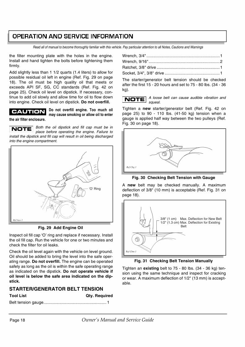
OPERATION AND SERVICE INFORMATION
Page 18 Owner’s Manual and Service Guide
Read all of manual to become thoroughly familiar with this vehicle. Pay particular attention to all Notes, Cautions and Warnings
the filter mounting plate with the holes in the engine.Install and hand tighten the bolts before tightening themfirmly.
Add slightly less than 1 1/2 quarts (1.4 liters) to allow forpossible residual oil left in engine (Ref. Fig. 29 on page18). The oil must be high quality oil that meets orexceeds API SF, SG, CC standards (Ref. Fig. 42 onpage 25). Check oil level on dipstick. If necessary, con-tinue to add oil slowly and allow time for oil to flow downinto engine. Check oil level on dipstick. Do not overfill.
Do not overfill engine. Too much oilmay cause smoking or allow oil to enter
the air filter enclosure.
Both the oil dipstick and fill cap must be inplace before operating the engine. Failure to
install the dipstick and fill cap will result in oil being dischargedinto the engine compartment.
Inspect oil fill cap ‘O’ ring and replace if necessary. Installthe oil fill cap. Run the vehicle for one or two minutes andcheck the filter for oil leaks.
Check the oil level again with the vehicle on level ground.Oil should be added to bring the level into the safe oper-ating range. Do not overfill. The engine can be operatedsafely as long as the oil is within the safe operating rangeas indicated on the dipstick. Do not operate vehicle ifoil level is below the safe area indicated on the dip-stick.
STARTER/GENERATOR BELT TENSIONTool List Qty. Required
Belt tension gauge....................................................... 1
Wrench, 3/4" ................................................................1Wrench, 9/16" ..............................................................2Ratchet, 3/8" drive .......................................................1Socket, 3/4", 3/8" drive ................................................1
The starter/generator belt tension should be checkedafter the first 15 - 20 hours and set to 75 - 80 lbs. (34 - 36kg).
A loose belt can cause audible vibration andsqueal.
Tighten a new starter/generator belt (Ref. Fig. 42 onpage 25) to 90 - 110 lbs. (41-50 kg) tension when agauge is applied half way between the two pulleys (Ref.Fig. 30 on page 18).
A new belt may be checked manually. A maximumdeflection of 3/8" (10 mm) is acceptable (Ref. Fig. 31 onpage 18).
Tighten an existing belt to 75 - 80 lbs. (34 - 36 kg) ten-sion using the same technique and inspect for crackingor wear. A maximum deflection of 1/2" (13 mm) is accept-able.
Fig. 29 Add Engine Oil
'O' Ring
Ref Aeo 1
Fig. 30 Checking Belt Tension with Gauge
Fig. 31 Checking Belt Tension Manually
Ref Cbg 1
3/8" (1 cm) Max. Deflection for New Belt1/2" (1.3 cm) Max. Deflection for Existing Belt
Ref Cbm 1

OPERATION AND SERVICE INFORMATION
Page 19Owner’s Manual and Service Guide
Read all of manual to become thoroughly familiar with this vehicle. Pay particular attention to all Notes, Cautions and Warnings
Adjusting the BeltLoosen the starter/generator pivot bolt.
While holding the lower adjusting nut with a wrench,loosen the upper jam nut with another wrench. Move thelower nut up or down the adjustment bolt until proper belttension is achieved. Hold the lower nut in place andtighten the upper jam nut against it (Ref. Fig. 32 on page19).
Tighten the starter/generator pivot bolt.
BATTERY CLEANING
To reduce the possibility of damage tovehicle or floor, neutralize acid before
rinsing battery.
To reduce the possibility of damage to electrical componentswhile cleaning, do not use a pressure washer.
Cleaning should take place per the Periodic ServiceSchedule (Ref. Fig. 21 on page 14).
When cleaning the outside of the battery and terminals,first spray with a solution of sodium bicarbonate (bakingsoda) and water to neutralize any acid deposits beforerinsing with clear water.
Use of a water hose without first neutralizing any acid,will move acid from the top of the battery to another areaof the vehicle or storage facility where it will attack themetal structure or the concrete/asphalt floor. Additionally,a residue will be left on the battery which is conductiveand will contribute to the discharge of the battery.
To reduce the possibilityof battery explosion thatcould result in severe
injury or death, do not use metallic spray wand toclean battery and keep all smoking materials, openflame or sparks away from the battery.
The correct cleaning technique is to spray the top andsides of the battery with a solution of sodium bicarbonate(baking soda) and water. This solution is best appliedwith a garden type sprayer equipped with a non metallicspray wand or a plastic spray bottle. The solutionshould consist of the amounts of sodium bicarbonate(baking soda) and clear water shown below (Ref. Fig. 33on page 19). In addition to the battery, special attentionshould be paid to metal components adjacent to the bat-tery which should also be sprayed with the sodium bicar-bonate (baking soda) solution.
Allow the solution to sit for at least three minutes; use asoft bristle brush or cloth to wipe the tops of the battery toremove any residue that could contribute to the self dis-charge of the battery. Rinse the entire area with low pres-sure clear water. Do not use a pressure washer.
BRAKES
To reduce the possibilityof severe injury or death,always evaluate pedal
travel before operating a vehicle to verify some brak-ing function is present.All driving brake tests must be done in a safe locationwith regard for the safety of all personnel.
Fig. 32 Adjusting Belt Tension
Jam Nut
Adjusting Nut
Ref Abt 1
! !�
Fig. 33 Preparing Acid Neutralizing Solution
1 1/2 gallons(6 liters)
Clear Water
1/4 Cup (60 ml)Sodium Bicarbonate
(Baking Soda)
2 Gallon(7.5 liter) GardenSprayer
Ref Pns 1
1 quart(1 liter)
Clear Water
2 Teaspoons(10 ml)Sodium
Bicarbonate(Baking Soda)
PlasticSprayBottle
ORNon
MetallicWand
! !�
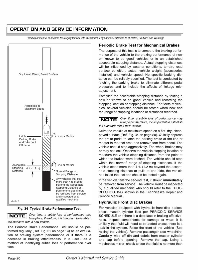
OPERATION AND SERVICE INFORMATION
Page 20 Owner’s Manual and Service Guide
Read all of manual to become thoroughly familiar with this vehicle. Pay particular attention to all Notes, Cautions and Warnings
Over time, a subtle loss of performance maytake place; therefore, it is important to establish
the standard with a new vehicle.
The Periodic Brake Performance Test should be per-formed regularly (Ref. Fig. 21 on page 14) as an evalua-tion of braking system performance or if there is adecrease in braking effectiveness. It is useful as amethod of identifying subtle loss of performance overtime.
Periodic Brake Test for Mechanical BrakesThe purpose of this test is to compare the braking perfor-mance of the vehicle to the braking performance of newor ‘known to be good’ vehicles or to an establishedacceptable stopping distance. Actual stopping distanceswill be influenced by weather conditions, terrain, roadsurface condition, actual vehicle weight (accessoriesinstalled) and vehicle speed. No specific braking dis-tance can be reliably specified. The test is conducted bylatching the parking brake to eliminate different pedalpressures and to include the affects of linkage mis-adjustment.
Establish the acceptable stopping distance by testing anew or ‘known to be good’ vehicle and recording thestopping location or stopping distance. For fleets of vehi-cles, several vehicles should be tested when new andthe range of stopping locations or distances recorded.
Over time, a subtle loss of performance maytake place; therefore, it is important to establish
the standard with a new vehicle.
Drive the vehicle at maximum speed on a flat, dry, clean,paved surface (Ref. Fig. 34 on page 20). Quickly depressthe brake pedal to latch the parking brake at the line ormarker in the test area and remove foot from pedal. Thevehicle should stop aggressively. The wheel brakes mayor may not lock. Observe the vehicle stopping location ormeasure the vehicle stopping distance from the point atwhich the brakes were latched. The vehicle should stopwithin the ‘normal’ range of stopping distances. If thevehicle stops more than 4 ft. (1.2 m) beyond the accept-able stopping distance or pulls to one side, the vehiclehas failed the test and should be tested again.
If the vehicle fails the second test, it should immediatelybe removed from service. The vehicle must be inspectedby a qualified mechanic who should refer to the TROU-BLESHOOTING section in the Technicain’s Repair andService Manual.
Hydraulic Front Disc BrakesFor vehicles equipped with hydraulic front disc brakes,check master cylinder fluid per PERIODIC SERVICESCHEDULE or if there is a decrease in braking effective-ness. Inspect components for damage or wear. It isunlikely that fluid will need to be added unless there is aleak in the system. Raise the front of the vehicle (Seeraising the vehicle). Remove passenger side wheel/tire.Carefully wipe off dirt and debris from master cylinderand cap before opening. Remove the cap. Using amechanics mirror, check to see that fluid is no more than
Fig. 34 Typical Brake Performance Test
LatchParking Brakeand Take FootOff Pedal
Line or Marker
AcceptableStoppingDistance Normal Range of
Stopping Distance
Any vehicles that stop more than 4 ft. (1.2 m) beyond the Acceptable Stopping Distance or pulls to one side should be removed from service and inspected by a qualified mechanic
Accelerate ToMaximum Speed
4 ft. (1.2 m)Line or Marker
Dry, Level, Clean, Paved Surface
Ref Bpt 1

OPERATION AND SERVICE INFORMATION
Page 21Owner’s Manual and Service Guide
Read all of manual to become thoroughly familiar with this vehicle. Pay particular attention to all Notes, Cautions and Warnings
1/4" below top of reservoir. Add DOT 3 or 4 fluid asrequired.
AIR INTAKE AND COOLING FINS
T o p reve nt p oss ib leb u r n s , e n g in e p a r t sshould be kept clean to
reduce risk of overheating and ignition of accumulat-ed debris.
After every off road use, allow to cool and then check fora build up of dirt and debris in the air intake and coolingfins. Dirt and debris may clog the engine’s air coolingsystem. Clean areas shown to prevent engine damage(Ref. Fig. 35 on page 21) (Ref. Fig. 36 on page 21). Keeplinkages, springs and controls clean. Keep area aroundmuffler free of any combustible material.
REAR AXLEThe rear axle is provided with a lubricant level check pluglocated on the driver side at the rear of the housing (Ref.Fig. 37 on page 21). Unless leakage of rear axle lubricantis evident, an annual lubricant check is sufficient.
Checking the Lubricant LevelTool List Qty. Required
Socket, 13 mm, 3/8" drive ........................................... 1Ratchet, 3/8" drive ....................................................... 1Funnel ......................................................................... 1
Clean the area around the check and fill plugs. Removethe check plug. The correct lubricant level is just belowthe bottom of the threaded hole (Ref. Fig. 42 on page25). If lubricant is to be added, remove the fill plug andadd lubricant using a funnel. Add lubricant slowly untillubricant starts to seep from the check plug hole. Installthe check plug and the fill plug. In the event that the lubri-cant is to be replaced, a drain plug is provided at the bot-tom of the differential housing.
AIR CLEANER INSPECTION AND REPLACE-MENT
To reduce the possibility of enginedamage, be sure that bottom tabs of
cover are installed in enclosure and top of cover is installedunder top tabs. Secure all spring clips.
The air cleaner unit on the vehicle is a dry unit.Do not use oil on the filter element or any part
of the unit. To aide installation and sealing, petroleum jelly maybe applied to back side of cover tabs and each side of filterseal.
The air cleaner is attached to the engine and may beaccessed by raising the seat. Inspect and replace air fil-ter in accordance with the Periodic Service Schedule(Ref. Fig. 21 on page 14). The air cleaner element isaccessible by unsnapping top clips from the air box andswinging the cover open. Remove cover and air filter ele-ment (Ref. Fig. 38 on page 22). Clean inside of cover andenclosure. Install the new element in the same way theold filter was removed, being sure that the filter seal is
Fig. 35 Cleaning Air Intake
Fig. 36 Cleaning the Cooling Fins
! !�
Ref Cai 1
Ref Ccf 1
Fig. 37 Add, Check and Drain Rear Axle Lubricant
Check Plug
Drain PlugRef Raf 2
Fill Plug

OPERATION AND SERVICE INFORMATION
Page 22 Owner’s Manual and Service Guide
Read all of manual to become thoroughly familiar with this vehicle. Pay particular attention to all Notes, Cautions and Warnings
correctly installed. Insert cover into the lower portion ofthe enclosure and swing it up into place. Squeeze hous-ing together and secure with top clips. Be sure cover fitsunder tabs and all clips are fastened securely.
Cleaning the Air Filter Element
Do not use compressed air to clean theair filter; doing so will damage the filter
which may result in damage to the engine.
If the element is in acceptable condition, loose dirt maybe removed by tapping the filter lightly. Do not use oil onthe filter element or any part of the unit.
Canister Type Air CleanerThe air cleaner element is accessible by unsnapping theclips on the air canister and removing the cover and airfilter element (Ref. Fig. 39 on page 22). Clean inside ofcover, canister and dust collector. Install the element andcover the same way they were removed. Be sure thepositioning arrow on cover is pointing upward and allclips are fastened securely.
Cleaning the Air Filter Element
Do not use compressed air to clean theair filter; doing so will damage the filter
which may result in damage to the engine.
If the element is in acceptable condition, loose dirt maybe removed by tapping the filter lightly. Do not use oil onthe filter element or any part of the unit. Install the ele-
ment in the same way it was removed, being sure thatthe clips are fastened securely.
LUBRICATION
Do not use more than three (3) pumpsof grease in any grease fitting at any
one time. Excess grease may cause grease seals to fail orgrease migration into areas that could damage components.
Putting more than three pumps of grease in a grease fit-ting could damage grease seals and cause prematurebearing failure (Ref. Fig. 40 on page 22).
SPARK PLUGSTool List Qty. Required
Spark plug socket, 13/16", 1/2" drive...........................1Ratchet, 1/2" drive .......................................................1Plug gauge, wire type ..................................................1Anti-seize compound ................................................ARTorque wrench, 1/2" drive, ft. lbs. ................................1
Use care not to over-tighten the plug.Over-tightening can cause damage to
the aluminum cylinder head threads.
Fig. 38 Air Cleaner
Ref Air 1
Front and back sidesof tabs may belubricated withpetroleum jelly
Front and back sidesof air filter seal maybe lubricated with
petroleum jelly
Fig. 39 Canister Type Air Cleaner
Fig. 40 Lubrication Points
Dust Collector
Air Cleaner Cover
Air Cleaner Canister
Air Filter Element
Ref Air 2
View From Underside Of Vehicle
Rack Ball Joint
Ref Lub 1

OPERATION AND SERVICE INFORMATION
Page 23Owner’s Manual and Service Guide
Read all of manual to become thoroughly familiar with this vehicle. Pay particular attention to all Notes, Cautions and Warnings
Remove and inspect the spark plugs at intervals indi-cated in the Periodic Service Schedule (Ref. Fig. 21 onpage 14). All new spark plugs should be properly gappedbefore installation (Ref. Fig. 42 on page 25). Apply a lightcoat of anti-seize compound and tighten to 18 ft. lbs. (24Nm) torque.
Fouled spark plugs are indicated by a wet, black appear-ance. This could be caused by a dirty air filter element orother restrictions in the air intake system. Incorrectlyadjusted valves, spark plug wires which are in poor con-dition or poor quality fuel could also contribute to theproblem.
PROLONGED STORAGE
To reduce the possibilityof severe injury or deathresulting from a possi-
ble explosion:
Do not handle fuel in an area that is not adequate-ly ventilated. Do not smoke near the fuel tank orrefuel near open flame or electrical items whichcould produce a spark.Store vehicle in a clean, dry area. Do not store insame area as a stove, furnace, water heater, orother appliance that uses a pilot light or has adevice that can create a spark.When refueling, inspect the fuel cap for leaks orbreaks that could result in fuel spillage.Always wear safety glasses while refueling to pre-vent possible eye injury from gasoline or gasolinevapor.Keep hands, clothing and jewelry away from mov-ing parts. Use care not to contact hot objects.Raise the rear of the vehicle and support on jackstands before attempting to run the engine.
Preparing the engine for a prolonged storage period (30days or more) calls for a few simple steps to prevent abuild up of varnish and gum in the carburetor and corro-sion in the engine.
• Raise the rear of the vehicle and support on jackstands. Refer to ‘Lifting the Vehicle’ for proper lift-ing procedure and safety information.
• Disconnect the fuel hose at the fuel tank andplug hose.
• With proper ventilation, depress the acceleratorpedal and allow engine to run until it stops due tolack of fuel.
• Remove spark plugs (Refer to SPARK PLUGS onpage 22) and pour about 1 oz. (30 ml) of engineoil into each cylinder. Replace spark plugs,ground spark plug wires and use starter to turnengine over a few seconds to distribute oil.
• Add a gasoline additive to the tank in accordancewith the manufacturer’s recommendations.
• Reattach fuel line to tank and drive the vehicle forseveral minutes to circulate the additive throughthe carburetor.
• While engine is still warm, change oil (Refer toCHANGING THE OIL on page 16).
• Clean body, chassis and engine of debris, mud,chaff or grass (Refer to AIR INTAKE AND COOL-ING FINS on page 21).
HARDWAREPeriodically, the vehicle should be inspected for loosefasteners. Fasteners should be tightened in accordancewith the Torque Specifications table (Ref. Fig. 41 onpage 24).
Use care when tightening fasteners and refer to theTechnician’s Repair and Service Manual for specifictorque values.
Generally, three grades of hardware are used in the vehi-cle. Grade 5 hardware can be identified by the threemarks on the hexagonal head and grade 8 hardware isidentified by 6 marks on the head. Unmarked hardware isGrade 2 (Ref. Fig. 41 on page 24).
! !�
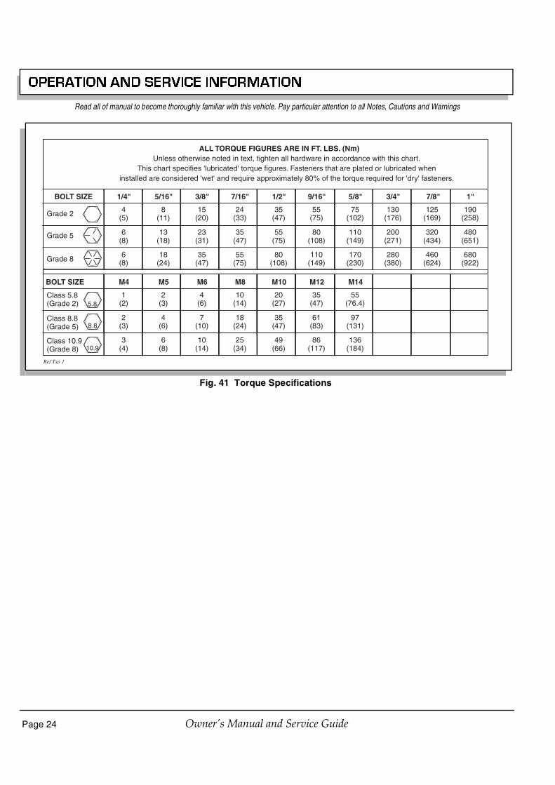
OPERATION AND SERVICE INFORMATION
Page 24 Owner’s Manual and Service Guide
Read all of manual to become thoroughly familiar with this vehicle. Pay particular attention to all Notes, Cautions and Warnings
Fig. 41 Torque Specifications
ALL TORQUE FIGURES ARE IN FT. LBS. (Nm)
BOLT SIZE
Grade 2
1/4" 5/16" 3/8" 7/16" 1/2" 9/16" 5/8" 3/4" 7/8" 1"
Unless otherwise noted in text, tighten all hardware in accordance with this chart.This chart specifies 'lubricated' torque figures. Fasteners that are plated or lubricated when
installed are considered 'wet' and require approximately 80% of the torque required for 'dry' fasteners.
4(5)
8(11)
15(20)
24(33)
35(47)
55(75)
75(102)
130(176)
125(169)
190(258)
Grade 5
Grade 8
6(8)
13(18)
23(31)
35(47)
55(75)
80(108)
110(149)
200(271)
320(434)
480(651)
6(8)
18(24)
35(47)
55(75)
80(108)
110(149)
170(230)
280(380)
460(624)
680(922)
BOLT SIZE
Class 5.8(Grade 2)
M4 M5 M6 M8 M10 M12 M14
1(2)
2(3)
4(6)
10(14)
20(27)
35(47)
55(76.4)
Class 8.8(Grade 5)
2(3)
4(6)
7(10)
18(24)
35(47)
61(83)
97(131)
Class 10.9(Grade 8)
3(4)
6(8)
10(14)
25(34)
49(66)
86(117)
136(184)
5.8
8.8
10.9
Ref Tsp 1

OPERATION AND SERVICE INFORMATION
Page 25Owner’s Manual and Service Guide
Read all of manual to become thoroughly familiar with this vehicle. Pay particular attention to all Notes, Cautions and Warnings
CAPACITIES AND REPLACEMENT PARTS
Fig. 42 Capacities and Replacement Parts
Fuel Tank / Fuel 6.0 gal (22.5 L) / 87 Octane
1 1/2 qt (1.4 L)
40 oz (1.2 L)
15 amp (P/N 35212-G01)
P/N 20209-G3
#912 (P/N 74005-G01)
#1157 (P/N 21759-G1)
P/N 26591-G01
P/N 72368-G01 Panel Filter
P/N 28463-G01 Canister Filter
NGK BPR4ES (P/N 25523-G3) 295cc
NGK BPR5ES (P/N 25523-G4) 350cc
.020 - .030" (.71 - .76 mm) Gap
P/N 26414-G01
P/N 72054-G01
Engine Oil
Rear Axle Oil
Fuse
Headlight Bulb
Marker Bulb
Turn Signal Bulb
#1157 (P/N 21759-G1)Tail Light Bulb
Oil Filter
Air Filter
Spark Plugs
Starter/Generator Belt
Clutch Belt
Ref Cap 10
OPERATION AND SERVICE INFORMATION
Page 26 Owner’s Manual and Service Guide
Read all of manual to become thoroughly familiar with this vehicle. Pay particular attention to all Notes, Cautions and Warnings

Page 27
GENERAL SPECIFICATIONS
Owner’s Manual and Service Guide
GENERAL SPECIFICATIONS

Page 28 Owner’s Manual and Service Guide
GENERAL SPECIFICATIONS
MPT™ 800STANDARD EQUIPMENT:WEIGHT (dry fuel tank) 780 lbs (355 kg) fuel capacity 36 lbs (16 kg)TIRES (4 ply rated) 18 x 8.50 x 8 (4 ply rated)TIRE PRESSURE 18 - 22 psi (124 - 152 kPa) LOAD CAPACITY 800 lbs (362 kg) (including operator, passenger, cargo and accessories)GROUND CLEARANCE 5 in (12.7 cm) at differentialCHASSIS Welded high yield strength tubular steel with powder coat paintBODY & FINISH Front: Flexible, impact resistant panels. Color coat/clear coat finish
Rear: Lightweight, replaceable steel panelsSAFETY Dash mounted key switch, reverse warning indicator, ’deadman’ accelerator control, integral
handgrip on hip restraints, manual forward/reverse selector, electric horn, differential skid plate, engine guard
LIGHTING PACKAGE Dual halogen headlights, optional taillights, brake lights, turn signalsSTEERING WHEEL Dual handgripsBRAKES Dual rear wheel mechanical, self-adjusting drum brakes. Combination service / park brake with
automatic parking brake release (accelerator kick-off). Optional hydraulic front disc brakesFRONT SUSPENSION Heavy duty leaf springs with hydraulic shock absorbersREAR SUSPENSION Heavy duty leaf springs with hydraulic shock absorbersSTEERING Self-compensating single reduction rack and pinionDASH PANEL Scuff resistant with four drink holders, 12 volt outlet, fuel gauge, low oil pressure indicator lightSEATING Formed fabric backed vinyl covers over cushion foam. Seating for operator and one passengerENGINE 9 hp (6.7 kW) rated, 4 cycle, 295cc twin cylinder air cooledVALVE TRAIN Overhead valve, overhead cam, belt driveLUBRICATION Pressurized oil system, washable permanent filterBALANCER Internal counter-rotating balance shaftIGNITION Solid State, electronic timing advance and RPM limiterCARBURETOR Fixed jet, remote pulse fuel pumpAIR CLEANER Replaceable dry cartridge elementDRIVE TRAIN Automatic, continuously variable transmission (CVT)ELECTRICAL SYSTEM External starter/generator, Solid State regulator, 12 volt maintenance free battery, 425 CCA, 60
minute reserveTRANSAXLE High efficiency differential with helical gears, 13.32:1 ratio, ground speed governor, forward and
reverse with neutral lockFUEL TANK 6 gal (23 L)SPEED 13 mph ± .5 mph (21 kph ± .8 kph)
Specifications subject to change without notice

Page 29
GENERAL SPECIFICATIONS
Owner’s Manual and Service Guide
MPT™ 1200STANDARD EQUIPMENT:WEIGHT (dry fuel tank) 860 lbs (390 kg) fuel capacity 36 lbs (16 kg)TIRES (4 ply rated) 18 x 8.50 x 8 (4 ply rated)TIRE PRESSURE 18 - 22 psi (124 - 152 kPa) LOAD CAPACITY 1200 lbs. (544 kg) (including operator, passenger, cargo and accessories)GROUND CLEARANCE 5 in (12.7 cm) at differentialCHASSIS Welded high yield strength tubular steel with powder coat paintBODY & FINISH Front: Flexible, impact resistant panels. Color coat/clear coat finish
Rear: Lightweight, replaceable steel panelsSAFETY Dash mounted key switch, reverse warning indicator, ’deadman’ accelerator control, integral
handgrip on hip restraints, manual forward/reverse selector, electric horn, differential skid plate, engine guard
LIGHTING PACKAGE Dual halogen headlights, optional taillights, brake lights, turn signalsSTEERING WHEEL Dual handgripsBRAKES Dual rear wheel mechanical, self-adjusting drum brakes. Combination service / park brake with
automatic parking brake release (accelerator kick-off). Optional hydraulic front disc brakesFRONT SUSPENSION Heavy duty leaf springs with hydraulic shock absorbersREAR SUSPENSION Heavy duty leaf springs with hydraulic shock absorbersSTEERING Self-compensating single reduction rack and pinionDASH PANEL Scuff resistant with four drink holders, fuel gauge, low oil pressure indicator lightSEATING Formed fabric backed vinyl covers over cushion foam. Seating for operator and one passengerENGINE 11 hp (8.2 kW) rated, 4 cycle, 350cc twin cylinder air cooledVALVE TRAIN Overhead valve, overhead cam, belt driveLUBRICATION Pressurized oil system, washable permanent filterBALANCER Internal counter-rotating balance shaftIGNITION Solid State, electronic timing advance and RPM limiterCARBURETOR Fixed jet, remote pulse fuel pumpAIR CLEANER Replaceable dry cartridge elementDRIVE TRAIN Automatic, continuously variable transmission (CVT)ELECTRICAL SYSTEM External starter/generator, Solid State regulator, 12 volt maintenance free battery, 425 CCA, 60
minute reserveTRANSAXLE High efficiency differential with helical gears, 13.32:1 ratio, ground speed governor, forward and
reverse with neutral lockFUEL TANK 6 gal (23 L)SPEED 13 mph ± .5 mph (21 kph ± .8 kph)
Specifications subject to change without notice

Page 30 Owner’s Manual and Service Guide
GENERAL SPECIFICATIONS
INDUSTRIAL™ 800STANDARD EQUIPMENT:WEIGHT (dry fuel tank) 780 lbs (355 kg) fuel capacity 36 lbs (16 kg)TIRES (4 ply rated) 18 x 5.70 x 8 (4 ply rated)TIRE PRESSURE 75 psi (515 kPa) LOAD CAPACITY 800 lbs. (362 kg) (including operator, passenger, cargo and accessories)GROUND CLEARANCE 5 in (12.7 cm) at differentialCHASSIS Welded high yield strength tubular steel with powder coat paintBODY & FINISH Front: Flexible, impact resistant panels. Color coat/clear coat finish
Rear: Lightweight, replaceable steel panelsSAFETY Dash mounted key switch, reverse warning indicator, ’deadman’ accelerator control, integral
handgrip on hip restraints, manual forward/reverse selector, electric horn, differential skid plate, engine guard
LIGHTING PACKAGE Dual halogen headlights, optional taillights, brake lights, turn signalsSTEERING WHEEL Dual handgripsBRAKES Dual rear wheel mechanical, self-adjusting drum brakes. Combination service / park brake with
automatic parking brake release (accelerator kick-off). Optional hydraulic front disc brakesFRONT SUSPENSION Heavy duty leaf springs with hydraulic shock absorbersREAR SUSPENSION Heavy duty leaf springs with hydraulic shock absorbersSTEERING Self-compensating single reduction rack and pinionDASH PANEL Scuff resistant with four drink holders, 12 volt outlet, fuel gauge, low oil pressure indicator lightSEATING Formed fabric backed vinyl covers over cushion foam. Seating for operator and one passengerENGINE 9 hp (6.7 kW) rated, 4 cycle, 295cc twin cylinder air cooledVALVE TRAIN Overhead valve, overhead cam, belt driveLUBRICATION Pressurized oil system, washable permanent filterBALANCER Internal counter-rotating balance shaftIGNITION Solid State, electronic timing advance and RPM limiterCARBURETOR Fixed jet, remote pulse fuel pumpAIR CLEANER Replaceable dry cartridge elementDRIVE TRAIN Automatic, continuously variable transmission (CVT)ELECTRICAL SYSTEM External starter/generator, Solid State regulator, 12 volt maintenance free battery, 425 CCA, 60
minute reserveTRANSAXLE High efficiency differential with helical gears, 13.32:1 ratio, ground speed governor, forward and
reverse with neutral lockFUEL TANK 6 gal (23 L)SPEED 13 mph ± .5 mph (21 kph ± .8 kph)
Specifications subject to change without notice

Page 31
GENERAL SPECIFICATIONS
Owner’s Manual and Service Guide
INDUSTRIAL™ 1200STANDARD EQUIPMENT:WEIGHT (dry fuel tank) 860 lbs (390 kg) fuel capacity 36 lbs (16 kg)TIRES (4 ply rated) 18 x 5.70 x 8 (4 ply rated)TIRE PRESSURE 75 psi (515 kPa) LOAD CAPACITY 1200 lbs (544 kg) (including operator, passenger, cargo and accessories)GROUND CLEARANCE 5 in (12.7 cm) at differentialCHASSIS Welded high yield strength tubular steel with powder coat paintBODY & FINISH Front: Flexible, impact resistant panels. Color coat/clear coat finish
Rear: Lightweight, replaceable steel panelsSAFETY Dash mounted key switch, reverse warning indicator, ’deadman’ accelerator control, integral
handgrip on hip restraints, manual forward/reverse selector, electric horn, differential skid plate, engine guard
LIGHTING PACKAGE Dual halogen headlights, optional taillights, brake lights, turn signalsSTEERING WHEEL Dual handgripsBRAKES Dual rear wheel mechanical, self-adjusting drum brakes. Combination service / park brake with
automatic parking brake release (accelerator kick-off). Optional hydraulic front disc brakesFRONT SUSPENSION Heavy duty leaf springs with hydraulic shock absorbersREAR SUSPENSION Heavy duty leaf springs with hydraulic shock absorbersSTEERING Self-compensating single reduction rack and pinionDASH PANEL Scuff resistant with four drink holders, fuel gauge, low oil pressure indicator lightSEATING Formed fabric backed vinyl covers over cushion foam. Seating for operator and one passengerENGINE 11 hp (8.2 kW) rated, 4 cycle, 350cc twin cylinder air cooledVALVE TRAIN Overhead valve, overhead cam, belt driveLUBRICATION Pressurized oil system, washable permanent filterBALANCER Internal counter-rotating balance shaftIGNITION Solid State, electronic timing advance and RPM limiterCARBURETOR Fixed jet, remote pulse fuel pumpAIR CLEANER Replaceable dry cartridge elementDRIVE TRAIN Automatic, continuously variable transmission (CVT)ELECTRICAL SYSTEM External starter/generator, Solid State regulator, 12 volt maintenance free battery, 425 CCA, 60
minute reserveTRANSAXLE High efficiency differential with helical gears, 13.32:1 ratio, ground speed governor, forward and
reverse with neutral lockFUEL TANK 6 gal (23 L)SPEED 13 mph ± .5 mph (21 kph ± .8 kph)
Specifications subject to change without notice

Page 32 Owner’s Manual and Service Guide
GENERAL SPECIFICATIONS
Fig. 44 Vehicle Dimensions
MPT™ 800INDUSTRIAL™ 800
MPT™ 1200INDUSTRIAL™ 1200
103 in (262 cm)
(Rear)38 in (97 cm)
(Front)37.5 in (95 cm)
35 in (89 cm)
10 in(25 cm)47 in
(119 cm)
47 in(119 cm)
66 in (168 cm)
111 in (282 cm)
11.5 in(29 cm)
18 in(46 cm)
42.5 in (108 cm)
50 in(127 cm)
(Rear)38 in (97 cm)
(Front)37.5 in (95 cm)
47 in( 119 cm)
77 in (196 cm)

Page 33
GENERAL SPECIFICATIONS
Owner’s Manual and Service Guide
Fig. 45 Vehicle Dimensions, Incline Specifications and Turning Clearance Diameter
RECOMMENDED MAX RAMP GRADE 25% or 14o MAX
RECOMMENDED MAX SIDE TILT25% or 14o MAX
TURNING CLEARANCE DIAMETER
MPT™ 800 19 ft (5.8 m)MPT™ 1200 22 ft (6.7 m)INDUSTRIAL™ 800 19 ft (5.8 m)INDUSTRIAL™ 1200 22 ft (6.7 m)

Page 34 Owner’s Manual and Service Guide
GENERAL SPECIFICATIONS
Notes:

Page 35Owner’s Manual and Service Guide
VEHICLE WARRANTIES
VEHICLE WARRANTIES

Page 36 Owner’s Manual and Service Guide
VEHICLE WARRANTIES
DOMESTIC WARRANTY(U.S. AND CANADA)
To obtain a copy of the limited warranty applicable to the vehicle, call or write a local distributor, authorized Branch or the Warranty Department with vehicle serial number and manufacturer date code.

Page 37
VEHICLE WARRANTIES
Owner’s Manual and Service Guide
2004 INTERNATIONAL WARRANTY(ALL COUNTRIES OUTSIDE THE U.S. AND CANADA)
E-Z-GO Division of Textron, Inc. ("E-Z-GO") warrants to the Original Retail Purchaser or the Original Retail Lessee that any 2004 E-Z-GO vehicle and/or Battery Charger shall be free from any defects in material or workmanship for one year from the date of installation at the customer's location with respect to parts and labor.
EXCLUSIONS: Specifically excluded from any E-Z-GO warranty are adjustments/repairs made due to normal wear beyond the first 180 days, routine maintenance items, cosmetic deterioration, and electrical components which are susceptible to fluctuations in current beyond the control of E-Z-GO. This warranty also does not apply to Acts of God or other events over which E-Z-GO has no control. Transportation charges for warranty service, as well as freight charges to receive warranty parts are excluded from this warranty and all replaced parts shall become the property of E-Z-GO. This warranty also excludes batteries, tires, and Lester battery chargers which are warranted by their respective manufacturer.
REMEDY: The sole remedy under this warranty and E-Z-GO's only obligation in the event of a defect in the vehicle/battery charger, is that E-Z-GO will, at its sole option, repair or replace any defective parts. This remedy precludes all other remedies including any lawsuits, claims or other proceedings alleging strict liability, negligence of contract or any cause of action. E-Z-GO reserves the right to improve or change the design of any E-Z-GO vehicle or battery charger without assuming any responsibility to modify previously manufactured vehicles or battery chargers.
DISCLAIMER: THIS WARRANTY IS MADE IN LIEU OF ALL OTHER WARRANTIES, IMPLIED OR EXPRESSED, INCLUDING ANY WARRANTY OF MERCHANTABILITY OR FITNESS FOR A PARTICULAR PURPOSE. TGTSP WILL FURTHER DISCLAIM ANY LIABILITY FOR INCIDENTAL OR CONSEQUENTIAL DAMAGES, TO INCLUDE BUT NOT BE LIMITED TO, PERSONAL INJURY OR PROPERTY DAMAGE ARISING FROM ANY DEFECT IN THE VEHICLE/BATTERY CHARGER.
No agent, employee or representative of E-Z-GO, or any person has any authority to bind E-Z-GO to any other agreement, representation, or warranty concerning the goods sold under this warranty.
WARNING: ANY MODIFICATION OR CHANGE TO THE VEHICLE OR BATTERY CHARGER WHICH ALTERS THE WEIGHT DISTRIBUTION OF THE VEHICLE, ITS STABILITY, INCREASES THE SPEED, OR ALTERS THE OUTPUT OF THE BATTERY CHARGER BEYOND THE FACTORY SPECIFICATION, CAN CAUSE PERSONAL INJURY. DO NOT MAKE ANY SUCH MODIFICATION OR CHANGE. E-Z-GO PROHIBITS, AND DISCLAIMS RE-SPONSIBILITY FOR, ANY SUCH MODIFICATIONS OR ANY OTHER ALTERATION WHICH WOULD ADVERSE-LY AFFECT THE SAFETY OF VEHICLE OR BATTERY CHARGER.
VOIDING OF WARRANTY: THIS, AND ANY OTHER WARRANTY SHALL BE VOID IF THE VEHICLE OR BAT-TERY CHARGER IS ABUSED OR OTHERWISE NOT USED IN ITS INTENDED MANNER; IS IN AN ACCIDENT OR COLLISION; SHOWS INDICATIONS THAT THE SPEED GOVERNOR WAS ADJUSTED OR MODIFIED AL-LOWING THE VEHICLE TO OPERATE BEYOND E-Z-GO'S SPECIFICATIONS; SHOWS INDICATIONS THAT IT HAS BEEN ALTERED OR MODIFIED IN ANY WAY FROM E-Z-GO SPECIFICATIONS, INCLUDING BUT NOT LIMITED TO ALTERATIONS TO THE SPEED BRAKING SYSTEM, ELECTRICAL SYSTEM, STEERING OR OTH-ER OPERATING SYSTEMS OF THE VEHICLE OR; SHOWS INDICATIONS THAT ROUTINE MAINTENANCE WAS NOT PERFORMED WHEN, AND IN THE MANNER SPECIFIED IN THE E-Z-GO MAINTENANCE MANUAL. THIS WARRANTY SHALL BE VOID WITH RESPECT TO ANY DEFECT OR DAMAGE CAUSED BY, OR AS A RE-SULT OF, OR RELATED TO PARTS OR ACCESSORIES WHICH ARE NOT MANUFACTURED OR AUTHO-RIZED BY E-Z-GO, OR WERE NOT INSTALLED PER E-Z-GO'S INSTRUCTIONS, OR, FOR GASOLINE VEHI-CLES, THE USE OF NON-RECOMMENDED FUELS AND LUBRICANTS.
FOR FURTHER INFORMATION, CALL 1-706-798-4311 OR WRITE TO E-Z-GO Division of Textron, Inc. ATTEN-TION: WARRANTY DEPARTMENT, P.O. BOX 388, AUGUSTA, GEORGIA 30903-0388.

Page 38 Owner’s Manual and Service Guide
VEHICLE WARRANTIES
Notes:

Page 39
VEHICLE WARRANTIES - FEDERAL (2004)
Owner’s Manual and Service Guide
FEDERAL EMISSIONS COMPONENT DEFECT WARRANTY
EMISSIONS COMPONENT DEFECT WARRANTY COVERAGE - This emission warranty is applicable in all States, except the State of California
Fuji Heavy Industries Ltd. and E-Z-GO Division of Textron Augusta, Georgia, (herein “E-Z-GO”) warrant(s) to the initial retail purchaser and each subsequent owner, that this Non-road engine (herein “engine”) has been designed, built, and equipped to conform at the time of initial sale to all applicable regulations of the U.S. Environmental Pro-tection Agency (EPA), and that the engine is free of defects in materials and workmanship which would cause this engine to fail to conform with EPA regulations during its warranty period.
For the components listed under PARTS COVERED, the distributor, dealer, or service provider authorized by E-Z-GO will, at no cost to you, make the necessary diagnosis, repair, or replacement necessary to ensure that the engine complies with applicable U.S. EPA regulations.
EMISSISON COMPONENT DEFECT WARRANTY PERIOD
The warranty period for this engine begins on the date of sale to the initial purchaser and continues for a period of 2 years.
PARTS COVERED
Listed below are the parts covered by the Emission Components Defect Warranty. Some of the parts listed below may require scheduled maintenance and are warranted up to the first scheduled replacement point for that part.
1) Fuel Metering System (i) Carburetor and internal parts (and/or pressure regulator or fuel injection system)(ii) Air/fuel ratio feedback and control system, if applicable.(iii) Cold start enrichment system, if applicable.(iv) Regulator assy (gaseous fuel, if applicable)
2) Air Induction System(i) Intake manifold, if applicable(ii) Air filter.
3) Ignition System(i) Spark plugs. (ii) Magneto or electronic ignition system. (iii) Spark advance/retard system, if applicable.
4) Exhaust manifold, if applicable5) Miscellaneous Items Used in Above Systems
(i) Electronic controls, if applicable(ii) Hoses, belts, connectors, and assemblies.(iii) Filter lock assy (gaseous fuel, if applicable)
OBTAINING WARRANTY SERVICE
To obtain warranty service, take your engine to the nearest authorized E-Z-GO distributor, dealer, or service provid-er. Bring your sales receipts indicating date of purchase for this engine. The distributor, dealer, or service provider authorized by E-Z-GO will perform the necessary repairs or adjustments within a reasonable amount of time and furnish you with a copy of the repair order. All parts and accessories replaced under this warranty become the prop-erty of E-Z-GO.
WHAT IS NOT COVERED• Conditions resulting from tampering, misuse, improper adjustment (unless they were made by the distributor,
dealer, or service provider authorized by E-Z-GO during a warranty repair), alteration, accident, failure to use the recommended fuel and oil, or not performing required maintenance services.
• The replacement parts used for required maintenance services.• Consequential damages such as loss of time, inconvenience, loss of use of the engine or equipment, etc.• Diagnosis and inspection charges that do not result in warranty-eligible service being performed.• Any non-authorized replacement part, or malfunction of authorized parts due to use of non-authorized parts.
OWNER’S WARRANTY RESPONSIBILITIES
As the engine owner, you are responsible for the performance of the required maintenance listed in your owner’s manual. E-Z-GO recommends that you retain all receipts covering maintenance on your engine, but E-Z-GO cannot

Page 40 Owner’s Manual and Service Guide
VEHICLE WARRANTIES - FEDERAL (2004)
deny warranty solely for the lack of receipts or for your failure to ensure the performance of all scheduled mainte-nance.
As the engine owner, you should however be aware that E-Z-GO may deny warranty coverage if your engine or a part has failed due to abuse, neglect, improper maintenance or unapproved modifications.
You are responsible for presenting your engine to the nearest distributor, dealer, or service provider authorized by E-Z-GO when a problem exists.
If you have any questions regarding your warranty rights and responsibilities, you should contact the E-Z-GO War-ranty Department at 1-800-241-5855 for the information.
THINGS YOU SHOULD KNOW ABOUT THE EMISSION CONTROL SYSTEM WARRANTY
MAINTENANCE AND REPAIRS
You are responsible for the proper maintenance of the engine. You should keep all receipts and maintenance records covering the performance of regular maintenance in the event questions arise. These receipts and mainte-nance records should be transferred to each subsequent owner of the engine. E-Z-GO reserves the right to deny warranty coverage if the engine has not been properly maintained. Warranty claims will not be denied, however, solely because of the lack of required maintenance or failure to keep maintenance records.
MAINTENANCE, REPLACEMENT OR REPAIR OF EMISSION CONTROL DEVICES AND SYSTEMS MAY BE PERFORMED BY ANY REPAIR ESTABLISHMENT OR INDIVIDUAL; HOWEVER, WARRANTY REPAIRS MUST BE PERFORMED BY A DISTRIBUTOR, DEALER OR, SERVICE PROVIDER AUTHO-RIZED BY E-Z-GO. THE USE OF PARTS THAT ARE NOT EQUIVALENT IN PERFORMANCE AND DU-RABILITY TO AUTHORIZED PARTS MAY IMPAIR THE EFFECTIVENESS OF THE EMISSION CON-TROL SYSTEM AND MAY HAVE A BEARING ON THE OUTCOME OF A WARRANTY CLAIM.
If other than the parts authorized by E-Z-GO are used for maintenance replacements or for the repair of components affecting emission control, you should assure yourself that such parts are warranted by their manufacturer to be equivalent to the parts authorized by E-Z-GO in their performance and durability.
HOW TO MAKE A CLAIM
All repair qualifying under this limited warranty must be performed by a distributor, dealer, or service provider autho-rized by E-Z-GO. In the event that any emission-related part is found to be defective during the warranty period, you shall notify E-Z-GO Warranty Department at 1-800-241-5855 and you will be advised of the appropriate warranty service providers where the warranty repair can be performed.

Page 41
VEHICLE WARRANTIES - CALIFORNIA (2004)
Owner’s Manual and Service Guide
CALIFORNIA EMISSION CONTROL WARRANTY STATEMENTYOUR WARRANTY RIGHTS AND OBLIGATIONS
The California Air Resources Board and Fuji Heavy Industries Ltd. (herein "FUJI") are pleased to explain the emis-sion control system warranty on your 2004 and later small off-road engine (herein "engine"). In California, new en-gine must be designed, built and equipped to meet the State's stringent anti-smog standards. FUJI must warrant the emission control system on your engine for the period of time described below, provided there has been no abuse, neglect or improper maintenance of your engine.
Your emission control system may include parts such as the carburetor and the ignition system. Also included may be hoses, connectors and other emission-related assemblies.
Where a warrantable condition exists, FUJI will repair your engine at no cost to you including diagnosis, parts and labor.
MANUFACTURER'S WARRANTY COVERAGE:The 2004 and later engines are warranted for two (2) years. If any emission related part on your engine is defective, the part will be repaired or replaced by FUJI.
OWNER'S WARRANTY RESPONSIBILITIES:As the engine owner, you are responsible for the performance of the required maintenance listed in your Owner's Manual. FUJI recommends that you retain all receipts covering maintenance on your engine, but FUJI cannot deny warranty solely for the lack of receipts or for your failure to ensure the performance of all scheduled maintenance.As the engine owner, you should, however, be aware that FUJI may deny you warranty coverage if your engine or a part has failed due to abuse, neglect, improper maintenance or unapproved modifications.You are responsible for presenting your engine to a dealer, distributor or service provider authorized by E-Z-GO Division of Textron Augusta, Georgia, (herein "E-Z-GO") to which FUJI supplies the engine as soon as a problem exists. The warranty repairs should be completed in a reasonable amount of time, not to ex-ceed 30 days.
If you have any questions regarding your warranty rights and responsibilities, you should contact the E-Z-GO War-ranty Department at 1-800-241-5855.
LIMITED WARRANTY on Emission Control Systems
- California Only -FUJI, Tokyo, Japan, warrants to the owner of the 2004 and later engine that the engine (1) has been designed, built and equipped so as to conform at the time of manufacture with the applicable regulations of the California Air Re-sources Board, and (2) is free from defects in materials and workmanship which could cause it to fail to conform with those regulations as may be applicable in the terms and conditions stated below.
A. WARRANTY COMMENCEMENT DATEThe warranty period begins on the date the engine is delivered to a first retail purchaser.
B. LENGTH OF COVERAGEFUJI warrants to a first retail purchaser and each subsequent purchaser that the engine is free from defects in materials and workmanship which could cause the failure of a warranted emission-related part for a pe-riod of two (2) years after the date of delivery to the first retail purchaser.
C. WHAT IS COVERED:1. REPAIR OR REPLACEMENT PARTS
Repairs and replacement of any warranted part will be performed at no charge to you by an au-thorized dealer, distributor or a service provider. You may contact the E-Z-GO Warranty Depart-ment at 1-800-241-5855 to get the nearest appropriate location where your warranty repairs are performed.
2. WARRANTY PERIODThis warranty continues for a period of two (2) years and shall apply only to the repair, replace-ment or adjustment of the component parts which are not scheduled for replacement as required maintenance. Further, component parts which are scheduled only for regular inspection to the ef-fect of "repair or replace as necessary" shall be warranted for the warranty period. Any warranted

Page 42 Owner’s Manual and Service Guide
VEHICLE WARRANTIES - CALIFORNIA (2004)
part which is scheduled for replacement as required maintenance shall be warranted for the pe-riod of time up to the first scheduled replacement point for that part.
3. DIAGNOSISYou shall not be charged for diagnostic labor which leads to the determination that a warranted part is defective, if the diagnostic work is performed at an authorized dealer, distributor or service provider.
4. CONSEQUENTIAL DAMAGESIf a warranted part failed causing damages to other engine components, consult a service provid-er.
D. WHAT IS NOT COVERED1. This limited warranty does not cover any part which malfunctions, fails or is damaged due to failure to
follow the maintenance and operating instructions set forth in the 2004 and later Owner's Manual in-cluding:
(1) improper scheduled engine inspection and maintenance(2) improper maintenance of any warranted parts(3) improper installation, adjustment or repair of the engine or of any warranted part unless per-
formed by an authorized dealer(4) failure to follow recommendations on fuel use contained in the 2004 and later Owner's Manual(5) repairs performed outside of the authorized warranty service facilities(6) use of parts which are not authorized by FUJI
2. Add-on or modified partsThis warranty does not cover any part which malfunctions, fails or is damaged due to alterations by changing, adding to or removing parts from the engine.
3. Expenses incurred by processing warranty claimsFUJI, any authorized dealer, distributors and service providers shall not be liable for any loss of use of the engine, for any alternative usage, for any damage to goods, loss of time or inconve-nience.
E. HOW TO FILE A CLAIMAll repairs qualifying under this Limited Warranty must be performed by a dealer who sold you the engine or distributors or service providers authorized by E-Z-GO. In the event that any emission-related part is found to be defective during the warranty period, you should notify E-Z-GO Warranty Department at 1-800-241-5855 and you will be given the appropriate warranty service facilities where the warranty repair is per-formed.
F. WHERE TO GET WARRANTY SERVICEIt is recommended that warranty service be performed by the authorized dealer who sold you the engine, although warranty service will be performed by any authorized dealers, distributors and service providers anywhere in the United States. When warranty repair is needed, the engine must be brought to an autho-rized dealer, distributorship or service provider’s place of business during normal business hours. In all cas-es, a reasonable time, not to exceed 30 days, must be allowed for the warranty repair to be completed after the engine is received by the authorized dealer, distributor or service station.
G. MAINTENANCE, REPLACEMENT AND REPAIR OF EMISSION-RELATED PARTSOnly warranted engine replacement parts approved by FUJI should be used in the performance of any war-ranty maintenance or repairs on emission-related parts. If other than authorized parts are used for mainte-nance, replacement or repair of components affecting emission control, you should assure yourself that such parts are warranted by their manufacturer to be equivalent to authorized parts in performance and durability. FUJI, however, assumes no liability under this warranty with respect to parts other than autho-rized parts. The use of non-authorized replacement parts does not invalidate the warranty on other com-ponents unless the non-authorized parts cause damage to warranted parts.
H. PARTS COVERED UNDER THE CALIFORNIA EMISSIONS WARRANTY(1) Fuel Metering System
(i) Carburetor and internal parts (and/or pressure regulator or fuel injection system)(ii) Air/fuel ratio feedback and control system, if applicable(iii) Cold start enrichment system, if applicable(iv) Regulator assy (gaseous fuel, if applicable)
(2) Air Induction System(i) Intake manifold, if applicable(ii) Air filter
(3) Ignition System(i) Spark plugs(ii) Magneto or electronic ignition system.

Page 43
VEHICLE WARRANTIES - CALIFORNIA (2004)
Owner’s Manual and Service Guide
(iii) Spark advance/retard system, if applicable(4) Exhaust manifold, if applicable(5) Miscellaneous Items Used in Above Systems
(i) Electronic controls, if applicable(ii) Hoses, belts, connectors, and assemblies(iii) Filter lock assy (gaseous fuel, if applicable)
I. MAINTENANCE STATEMENTSIt is your responsibility to have all scheduled inspection and maintenance services performed at the times recommended in the 2004 and later Owner's Manual and to retain proof that inspection and maintenance services are performed at the times when recommended. FUJI will not deny a warranty claim solely be-cause you have no record of maintenance; however, FUJI may deny a warranty claim if your failure to per-form required maintenance resulted in the failure of warranted part. The proof which you maintain should be given to each subsequent owner of the engine. You are responsible for performing the scheduled main-tenance described in the Periodic Service Schedule of this manual. The scheduled maintenance is based on the normal engine operating schedule.

Page 44 Owner’s Manual and Service Guide
VEHICLE WARRANTIES - CALIFORNIA (2004)

Page 45Owner’s Manual and Service Guide
DECLARATION OF CONFORMITY
DECLARATION OF CONFORMITY(EUROPE ONLY)

Page 46 Owner’s Manual and Service Guide
DECLARATION OF CONFORMITY
DECLARATION OF CONFORMITY
NOT AVAILABLE
AT TIME OF
PUBLICATION

Page 47Owner’s Manual and Service Guide
DECLARATION OF CONFORMITY
DECLARATION OF CONFORMITY(EUROPE ONLY)

Page 48 Owner’s Manual and Service Guide
DECLARATION OF CONFORMITY

Page 49
DECLARATION OF CONFORMITY
Owner’s Manual and Service Guide

Page 50 Owner’s Manual and Service Guide
DECLARATION OF CONFORMITY
Notes:

Appendix A - 1
LABELS AND PICTOGRAMS
Owner’s Manual and Service Guide
LABELS AND PICTOGRAMS

Appendix A - 2 Owner’s Manual and Service Guide
LABELS AND PICTOGRAMS
35962G0135964G01
!
!
RF
< 14̊ 25%
P
F
!
< 14̊ 25%35962-G01
74443G01See Following Pages For Explanation Of These Pictograms: (1,2)
!
1. To Prevent Roll-Back On a Hill From a Stopped Position
3. Fully Release Park Brake
2. Apply Service Brake With Left Foot
4. Depress Accelerator While Releasing Service Brake As Vehicle Starts
74443G01
See Following Pages For
Explanation Of These
Pictograms: (19,43,44,45)
OFFON
71131-G01
71131G01
See Following Pages For
Explanation Of These
Pictograms: (2,3,4,6,9,36,37,
38,39,40,29)
71489G01
See Following PagesFor Explanation OfThese Pictograms:
(1,2)
35493G01 71771G01
See Following PagesFor Explanation Of
This Pictogram: (28)
28203G01See Following Pages
For Explanation OfThese Pictograms:
(20,1,21,22)
Pb35493-G01
2820
3-G
01
On Battery Under Seat
WARNING
Windshields do notprovide protectionfrom golf balls orother flying objects.
EGWHL14
See Following Pages For Explanation Of Pictogram: (30)
WARNING
Keep entire body
inside car.
27653G01
See Following Pages For Explanation Of Pictogram: (49)
DO NOT TAMPER WITH OR CHANGE THIS ADJUSTMENT OF THEGOVERNOR. FAILURE TO COMPLY COULD RESULT IN SERIOUSPERSONAL INJURY AND WILL VOID THE VEHICLE WARRANTY.
WARNING
24880G01
This Label Is Located On Governor Cover AtTop Of Rear Axle.
H O2
1 2 3
PP
PP PP74093-G01
74093G01
71419G01 (24)71417G01 (25)71415G01 (26)
See Following Pages For Explanation Of These Pictograms: (23,27,18,20,
22,17,15)
PP
MAX250 lbs.114 kg
MAX 4 in.10 cm
MAX14o / 25%
!35980G01
35980G0135980G02 35980G03 35980G04
See Following Pages For Explanation Of These Pictograms: (1,2,12,10,8,7,5,11)
74821G0174821G02 74821G03
See Following Pages For Explanation Of These Pictograms (1,2,12,10,8,11,51,7,5)
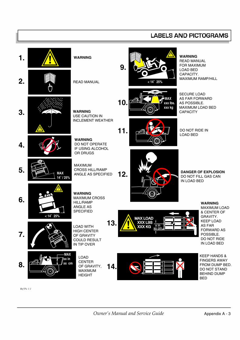
Appendix A - 3Owner’s Manual and Service Guide
LABELS AND PICTOGRAMS
WARNING
READ MANUAL
!
WARNINGUSE CAUTION ININCLEMENT WEATHER
WARNINGDO NOT OPERATEIF USING ALCOHOLOR DRUGS
MAX14˚ / 25%
MAXIMUM CROSS HILL/RAMP ANGLE AS SPECIFIED
!
< 14˚ 25%
WARNINGMAXIMUM CROSSHILL/RAMP ANGLE ASSPECIFIED
LOAD WITHHIGH CENTEROF GRAVITY COULD RESULTIN TIP OVER
MAXxx inxx cm
LOADCENTEROF GRAVITY,MAXIMUMHEIGHT
!
< 14˚ 25%
WARNINGREAD MANUAL FOR MAXIMUM LOAD BEDCAPACITY.MAXIMUM RAMP/HILL
MAXxxx lbs.xxx kg
SECURE LOADAS FAR FORWARDAS POSSIBLE.MAXIMUM LOAD BEDCAPACITY
DO NOT RIDE INLOAD BED
PP
DANGER OF EXPLOSIONDO NOT FILL GAS CAN IN LOAD BED
x inx inxx cmxx cm
MAX LOADMAX LOADXXX LBSXXX LBSXXX KGXXX KG
WARNINGMAXIMUM LOAD & CENTER OF GRAVITY.KEEP LOAD AS FAR FORWARD AS POSSIBLE.DO NOT RIDE IN LOAD BED
KEEP HANDS & FINGERS AWAY FROM DUMP BED.DO NOT STAND BEHIND DUMPBED
1.9.
10.
11.
12.
13.
14.
2.
3.
4.
5.
6.
7.
8.
Ref Pic 1-1

Appendix A - 4 Owner’s Manual and Service Guide
LABELS AND PICTOGRAMS
1 3H O2PP
CLEAN UP GASOLINE SPILLS WITH WATER BEFORE STARTING ENGINE
PPUNLEADED GASOLINE
PPGROUND FUEL PUMP
PP
DO NOT SPILL FUELON A HOTENGINE
NO TAMPERING.KEEP HANDS OUT
NEGATIVE GROUND BATTERY
DO NOT CONNECT POSITIVE BATTERY TERMINAL TO GROUND
SHORTING BATTERY TERMINALS MAY CAUSE EXPLOSION
DO NOT EXPOSE TO FLAME
WARNINGCORROSIVE
WARNINGLETHALVOLTAGE
WARNINGEXPLOSIVE
DO NOTDISPOSE OFBATTERIESIN LANDFILL
DO NOT DRIVE ON HIGHWAY
LOW OIL PRESSUREWINDSHIELDSDO NOTPROVIDE PROTECTION FROMFLYING OBJECTS
BATTERIES ARE HEAVY. USE CARE LIFTING
USE INSULATED TOOLS
WEAR EYE PROTECTION
NO SMOKING
HOT SURFACE
15.
16.
17.
18.
19.
20.
21.
22.
23.
24.
25.
26.
27.
28.
29.
30.
31.
32.
33.
34.
35.
Ref Pic 1-2

Appendix A - 5Owner’s Manual and Service Guide
LABELS AND PICTOGRAMS
P
F
OPERATE FROM DRIVERS SIDE ONLY
KEEP ARMS AND LEGS WITHIN VEHICLE
F
TO OPERATE VEHICLE IN FORWARD:✱ TURN KEY TO ON✱ MOVE DIRECTION SELECTOR TO FORWARD✱ DEPRESS ACCELERATOR PEDAL AND ACCELERATE SMOOTHLY
R
TO OPERATE VEHICLE IN REVERSE:✱ TURN KEY TO ON✱ MOVE DIRECTION SELECTOR TO REVERSE✱ AN AUDIBLE DEVICE WILL SOUND✱ DEPRESS ACCELERATOR PEDAL AND ACCELERATE SMOOTHLY
TO LEAVE A GASOLINE POWEREDVEHICLE IN PARK:✱ APPLY PARKING BRAKE✱ TURN KEY TO OFF✱ MOVE DIRECTION SELECTOR TO FORWARD
P
N
TO LEAVE AN ELECTRIC POWEREDVEHICLE IN PARK:✱ APPLY PARKING BRAKE✱ TURN KEY TO OFF✱ MOVE DIRECTION SELECTOR TO NEUTRAL
ON
OFF
KEEP CLEARHAND OR FINGERS CANBE TRAPPED
ONPOSITION
OFFPOSITION
HEADLIGHTS
UNLOCKED
LOCKED
DIFFERENTIAL LOCKED
36.
37.
38.
39.
40.
41.
42.
43.
44.45.
46.
47.
48.
49.WARNINGKEEP ENTIRE BODYINSIDE CAR
50.WARNINGPOSSIBILE ELECTRICARC OR BATTERYEXPLOSION. WEAREYE PROTECTION.
Ref Pic 1-3

Appendix A - 6 Owner’s Manual and Service Guide
LABELS AND PICTOGRAMS
MAXIMUM TAILGATELOAD
51.
Ref Pic 1-4

Read and understand the following warningsbefore attempting to operate the vehicle:
To prevent personalinjury or death, observethe following:
When vehicle is to be left unattended, engage parkingbrake, move direction selector to ‘F’ (forward)position, turn key to ‘OFF’ position and remove key.
Drive vehicle only as fast as terrain and safetyconsiderations allow. Consider the terrain and trafficconditions. Consider environmental factors whicheffect the terrain and the ability to control the vehicle.
Avoid driving fast down hill. Sudden stops or changeof direction may result in a loss of control. Use servicebrake to control speed when traveling down an incline.
Use extra care and reduced speed when driving onpoor surfaces, such as loose dirt, wet grass, gravel,etc.
All travel should be directly up or down hills.
Use extra care when driving the vehicle across anincline.
Stay in designated areas and avoid steep slopes. Usethe parking brake whenever the vehicle is parked.
Keep feet, legs, hands and arms inside vehicle at alltimes.
Avoid extremely rough terrain.
Check area behind the vehicle before operating inreverse.
Make sure the direction selector is in correct positionbefore attempting to start the vehicle.
Slow down before and during turns. All turns shouldbe executed at reduced speed.
Always bring vehicle to a complete stop beforeshifting the direction selector.
See GENERAL SPECIFICATIONS for vehicle load andseating capacity.
Read and understand the following text andwarnings before attempting to service vehicle:
In any product, components will eventually fail to performproperly as the result of normal use, age, wear or abuse.It is virtually impossible to anticipate all possible compo-nent failures or the manner in which each componentmay fail.Be aware that a vehicle requiring repair indicates that thevehicle is no longer functioning as designed and there-fore should be considered potentially hazardous. Useextreme care when working on any vehicle. When diag-nosing, removing or replacing any components that arenot operating correctly, take time to consider the safety ofyourself and others around you should the componentmove unexpectedly.
Some components are heavy, spring loaded, highly cor-rosive, explosive or may produce high amperage orreach high temperatures. Gasoline, carbon monoxide,battery acid and hydrogen gas could result in seriousbodily injury to the technician/mechanic and bystanders ifnot treated with the utmost caution. Be careful not toplace hands, face, feet or body in a location that couldexpose them to injury should an unforeseen situationoccur. Always use the appropriate tools listed in the tool list andwear approved safety equipment.
Before working on thevehicle, remove alljewelry (rings, watches,
necklaces, etc.)
Be sure that no loose clothing or hair can contactmoving parts.
Use care not to touch hot objects.
Raise rear of vehicle and support on jack standsbefore attempting to run or adjust powertrain.
Wear eye protection when working on or aroundvehicle. In particular, use care when working aroundbatteries, using solvents or compressed air.
Hydrogen gas is formed when charging batteries. Donot charge batteries without adequate ventilation.
Do not permit open flame or anyone to smoke in anarea that is being used for charging batteries. Aconcentration of 4% hydrogen gas or more isexplosive.
Engine exhaust gas (carbon monoxide) is deadly.Carbon monoxide is an odorless, colorless gas that isformed as a natural part of incomplete combustion ofhydrocarbon fuels. Carbon monoxide is a dangerousgas that can cause unconsciousness and ispotentially lethal.
The following are symptoms of carbon monoxideinhalation:• Dizziness• Vomiting• Intense headache• Muscular twitching• Weakness and sleepiness• Throbbing in temples
If any of these symptoms are experienced, get fresh airimmediately. Never work around or operate a vehiclein an environment that does not ventilate exhaustgases from the area.
! !�
! !�

SEGURANÇA
(OS MENSAGENS DE NOTA, DE AVISO E DE ATENÇAO SÃO COMPLEMENTADOS NO INTERIOR DA CONTRACAPA)
MENSAGENS DE NOTA, DE AVISO E DE ATENÇÃONeste manual existem diversas mensagens de NOTA,de AVISO e de ATENÇÃO.
Uma mensagem de NOTA indica aobrigatoriedade de observar uma determinada
condição.
Uma mensagem de AVISO indica uma situaçãoem que é possível a danificação do veículo.
U m a me n s a g e m d eATENÇÃO indica umasituação potencialmente
perigosa que pode provocar lesões corporais gravesou a morte.
Os utilizadores deverão respeitar cuidadosamente asmensagens de NOTA, de AVISO e de ATENÇÃO; amanutenção e reparação do veículo deverão serefectuadas apenas por pessoal especializado e complena consciência dos riscos inerentes a taisintervenções. A manutenção ou reparação inadequadapode danificar o veículo ou alterar as suascaracterísticas de segurança.
Os gases produzidos pore ste ve ícu lo co n têmprodutos químicos, que
em certas quantidades, poderão provocar doençascancerígenas, defeitos nos fetos ou outros danos noaparelho reprodutivo.
As emissões de gases do motor destes veículos,está de acordo com as regulações definidas pela
Agência de Protecção Ambiental (APA) dos Estados Unidos daAmérica (EUA) na altura do fabrico. As alterações oumodificações do motor, do combustível, da ignição ou dossistemas de entrada de ar poderão dar origem a coimasbastante significativas.
Os postos, terminais eacessórios relacionadoscom a bateria contêm
chumbo e seus compósitos. Lavar as mãos depois demanuseálos.
Este sistema de ignição de centelhas estáconforme todos os requisitos dos Regulamentos
Canadianos de Equipamentos de Interferência.
NOTA
AVISO
! !� ATENÇÃO
! !� ATENÇÃO
NOTA
! !�
NOTA
Se tiver quaisquer questões relacionadas com os assuntos desenvolvidos neste manual, por favor, contacte umrepresentante autorizado para obter esclarecimentos.
Leia e compreenda todas os autocolantes do veículo. Os autocolantes danificados ou em falta deverão ser substituídosimediatamente.
Em terrenos muito inclinados, o veículo pode deslocar-se a velocidades muito superiores às que são normais emterrenos planos. Para evitar a perda de controlo do veículo e possíveis acidentes graves, a velocidade deverá serlimitada à velocidade máxima de um veículo perfeitamente controlado em terreno plano. Ver ESPECIFICAÇÕESGERAIS. Para reduzir a velocidade, utilizar o travão de serviço.
A utilização do veículo com velocidades superiores ao máximo recomendado poderá conduzir à danificação completados órgãos da transmissão. Os danos provocados por excesso de velocidade, para além de poderem provocar aperda de controlo do veículo, são dispendiosos e, por serem considerados como utilização abusiva, não serãocobertos pela garantia do fabricante.
Para rebocar/transportar o veículo, consulte “TRANSPORTE DO VEÍCULO”.
Deverá ser utilizada alguma sinalética semelhante à que se ilustra para advertir acerca de situações que poderão resultarnuma condição insegura.
O presente manual deverá fazer parte integrante do livrete de manutenção, devendo ser entregue ao novo proprietário, emcaso de venda do veículo.
WASH HANDSAFTER HANDLING!
Battery posts,terminals and relatedaccessories contain
lead and lead compounds,chemicals known
to cause cancer andreproductive harm.
BATTERY WARNING
WASH HANDSAFTER HANDLING!
WARNING: Battery posts, terminals and relatedaccessories contain lead and lead compounds,
chemicals known to cause cancer and reproductive harm.
BATTERIESCONTAIN LEAD
AND RELATED PARTS
!
< 14˚ 25%
DO NOTDRIVE ACROSS
SLOPES INEXCESS OF 14˚
ATENÇÃO ATENÇÃO ATENÇÃO ATENÇÃO
CURVA APERTADAAPLICAR OS TRAVÕES
PARA REDUZIR A VELOCIDADE
CUESTA EMPINADAAPLICAR OS TRAVÕES
PARA REDUZIR A VELOCIDADE
CURVA APERTADAAPLICAR OS TRAVÕES
PARA REDUZIR A VELOCIDADE
Os postos, terminais e acessórios relacionados
com a bateria contêm chumbo e seus
compósitos; estes químicos são
conhecidos por causar cancro e problemas ao sistema reprodutivo.
LAVAR AS MÃOS DEPOIS DE MANUSEÁ-LOS!
AVISO DE BATERIA AS BATERIASE PEÇAS COM ELAS RELACIONADAS
CONTÊM CHUMBO
LAVAR AS MÃOS DEPOIS DE MANUSEÁ-LOS!
ATENÇÃO: Os postos, terminais e acessórios relacionados com a bateria contêm chumbo e
seus compósitos; estes químicos são conhecidos por causar cancro e problemas ao
sistema reprodutivo.
NÃO UTILIZAR EM RAMPAS COM
MAIS DE 14° DE INCLINAÇÃO

Página iManual do Propietário e Guia de Manutenção
MANUAL DO PROPIETÁRIOE GUIA DE MANUTENÇÃO
VEÍCULOS AGRÍCOLASA GASOLINA
MPT™ 800
MPT™ 1200
INDUSTRIAL™ 800
INDUSTRIAL™ 1200
E-Z-GO Division of TEXTRON, Inc. reserva-se o direito de efectuar alterações à concepção e características dos veículos sem obrigação de as introduzir emveículos previamente vendidos; a informação contida neste manual pode ser alterada sem aviso prévio.
E-Z-GO Division of TEXTRON, Inc. declina qualquer responsabilidade por erros contidos neste manual ou por danos indirectos ou lucros cessantes resultantesda utilização das informações contidas neste manual.
DEPARTAMENTO DE ASSISTÊNCIA A CLIENTES EUA TELEFONE: 1-800-241-5855 FAX: 1-800-448-8124
FORA DOS EUA TELEFONE: 010-1-706-798-4311 FAX: 010-1-706-771-4609
E-Z-GO DIVISION OF TEXTRON, INC., P.O.BOX 388, AUGUSTA, GEORGIA USA 30903-0388

Página ii
INFORMAÇÃO GERAL
Manual do Propietário e Guia de Manutenção
Este veículo foi concebido e fabricado nos Estados Unidos da América (EUA) como um ‘Veículo Universal’. As Normas e as Características listadas no texto seguinte referem-se
aos EUA, excepto quando indicado contrariamente.
A utilização de peças não genuínas (OEM) aprovadas poderá anular a garantia.
A utilização de peças não genuínas pode anular a garantia.
A falsificação ou modificação do regulador de forma a permitir que o veículo funcione de modo diferente das especificações da fábrica, invalidará a garantia do veículo.
Quando estiver a efectuar a manutenção de motores e a substituição de componentes deve fazê-lo de acordo com as especificações originais do veículo de forma a manter a
certificação de emissão Federal e Estatal dos Estados Unidos da América aplicável na altura do fabrico.
ARMAZENAMENTO PROLONGADO DA BATERIA
As baterias descarregam-se naturalmente ao longo do tempo. A velocidade desta descarga varia conforme a temperatura ambiente, a idade e estado das baterias.
Um bateria completamente carregada não congela durante a estação fria, a menos que a temperatura ambiente seja inferior a -60°C.

Página iii
ÍNDICE
Manual do Propietário e Guia de Manutenção
SEGURANÇA ........................................................................................ Interior da contracapa
INFORMAÇÃO GERAL .............................................................................................................. ii
INFORMAÇÕES DE SEGURANÇA ........................................................................................ vii
ANTES DA PRIMEIRA UTILIZAÇÃO ........................................................................................ 1Fig. 1 Tabela de verificações iniciais ........................................................................................1
CONTROLOS E INDICADORES ............................................................................................... 1INTERRUPTOR DE CHAVE/FARÓIS .................................................................................................................1
Fig. 2 Interruptor de chave/faróis, Indicador luminoso de baixapressão do óleo e Indicador do nível de combustível .....................................................2
SELECTOR DO SENTIDO DE MARCHA ...........................................................................................................2Fig. 3 Selector do sentido da marcha .......................................................................................2
COMANDO DO AR DE ADMISSÃO ....................................................................................................................2Fig. 4 Comando de admissão de ar ..........................................................................................2
INDICADOR DO NÍVEL DE COMBUSTÍVEL ......................................................................................................2LUZ INDICADORA DE PRESSÃO DO ÓLEO BAIXA .........................................................................................2PEDAL DO ACELERADOR .................................................................................................................................2
Fig. 5 Acelerador & travão ........................................................................................................3COMBINAÇÃO DE TRAVÃO DE SERVIÇO E TRAVÃO DE ESTACIONAMENTO ...........................................3BUZINA ................................................................................................................................................................3
Fig. 6 Botão da buzina ..............................................................................................................3
PLATAFORMA DE CARGA DE AÇO ....................................................................................... 3FUNCIONAMENTO DA PLATAFORMA DE ELEVAÇÃO MANUAL ...................................................................4
Fig. 7 Trinco da plataforma manual ..........................................................................................4Fig. 8 Barra de suporte da plataforma ......................................................................................4
FUNCIONAMENTO DA PLATAFORMA DE ELEVAÇÃO ELÉCTRICA ..............................................................4Fig. 9 Interruptor do elevador eléctrico .....................................................................................4
PLATAFORMA DE CARGA DE PLÁSTICO ............................................................................. 4FUNCIONAMENTO DA PLATAFORMA DE ELEVAÇÃO MANUAL ...................................................................5
Fig. 10 Trinco da plataforma manual ........................................................................................5Fig. 11 Suporte do gás .............................................................................................................5
FUNCIONAMENTO DO TAIPAL TRASEIRO ......................................................................................................5FUNCIONAMENTO DA PLATAFORMA DE ELEVAÇÃO ELÉCTRICA ..............................................................5
Fig. 12 Interruptor do elevador eléctrico ...................................................................................6
UTILILIZAÇÃO DO VEÍCULO ................................................................................................... 6RODAGEM ..........................................................................................................................................................6
Fig. 13 Verificar o nível do óleo na vareta de nível ...................................................................7ARRANQUE A FRIO ...........................................................................................................................................7INÍCIO DE MARCHA E CONDUÇÃO ..................................................................................................................7INICIAR A MARCHA NUMA POSIÇÃO INCLINADA ..........................................................................................7CIRCULAÇÃO COM O MOTOR DESENGRENADO OU DESLIGADO ..............................................................7COMBUSTÍVEL ...................................................................................................................................................7
Fig. 14 Abastecimento ..............................................................................................................8BATERIA .............................................................................................................................................................8ETIQUETAS E PICTOGRAMAS .........................................................................................................................8CAPOTA SOLAR E PÁRA-BRISAS ....................................................................................................................8TOMADA DE 12 V ...............................................................................................................................................8
Fig. 15 Tomada de 12 V ...........................................................................................................8REBOCAR UM ATRELADO ................................................................................................................................9
CUIDADOS E LIMPEZA DO VEÍCULO ..................................................................................... 9LIMPEZA DO VEÍCULO ......................................................................................................................................9PRODUTOS PARA CUIDAR DO VEÍCULO ........................................................................................................9

Página iv Manual do Propietário e Guia de Manutenção
ÍNDICE
REPARAÇÃO ........................................................................................................................... 10ELEVAÇÃO DO VEÍCULO ............................................................................................................................... 10
Fig. 16 Elevação do veículo ................................................................................................... 10RODAS E PNEUMÁTICOS .............................................................................................................................. 10
Fig. 17 Instalação das rodas .................................................................................................. 11SUBSTITUIÇÃO DE LÂMPADAS DOS FARÓIS .............................................................................................. 11
Fig. 18 Substituição das lâmpadas do farol dianteiro edo indicador de mudança de direcção ........................................................................ 12
SUBSTITUIÇÃO DE FUSÍVEIS ........................................................................................................................ 12Fig. 19 Substituição das lâmpadas das luzes de presença traseiras e das luzes de travão . 12
VEÍCULO COM A BATERIA DESCARREGADA .............................................................................................. 12
TRANSPORTE DO VEÍCULO ..................................................................................................12REBOQUE ........................................................................................................................................................ 12BLOQUEIO DE PONTO MORTO ..................................................................................................................... 12
Fig. 20 Bloqueio de ponto morto ............................................................................................ 13TRANSPORTE DO VEÍCULO SOBRE UM CAMIÃO ....................................................................................... 13
MANUTENÇÃO DE ROTINA ................................................................................................... 13LOCALIZAÇÃO DA CHAPA COM O NÚMERO DE SÉRIE .............................................................................. 14TABELA DE MANUTENÇÃO PERIÓDICA ....................................................................................................... 15
Fig. 21 Tabela de Manutenção Periódica .............................................................................. 15VERIFICAÇÃO DOS PNEUS ........................................................................................................................... 17VERIFICAÇÃO DO NÍVEL DO ÓLEO .............................................................................................................. 17
Fig. 22 Limpar toda a vareta de nível ..................................................................................... 17Fig. 23 Verificar o nível do óleo na vareta de nível ................................................................ 17
MUDANÇA DE ÓLEO ....................................................................................................................................... 18Fig. 24 Tabela de viscosidade do óleo ................................................................................... 18Fig. 25 Limpe a parte superior do motor ................................................................................ 18Fig. 26 Retire o filtro do óleo .................................................................................................. 18Fig. 27 Limpar o filtro do óleo ................................................................................................. 18Fig. 28 Descarregar o filtro do óleo ........................................................................................ 19Fig. 29 Acrescentar óleo do motor ......................................................................................... 19
TENSÃO DA CORREIA DO MOTOR DE ARRANQUE/ALTERNADOR .......................................................... 19Fig. 30 Verifique a tensão da correia com o indicador ........................................................... 19Fig. 31 Verifique a tensão da correia com o dedo ................................................................. 20Fig. 32 Afinação da tensão da correia ................................................................................... 20
LIMPEZA DA BATERIA .................................................................................................................................... 20Fig. 33 Preparação da solução de neutralização ................................................................... 20
TRAVÕES ......................................................................................................................................................... 21Fig. 34 Teste típico de desempenho de travagem ................................................................. 21
ENTRADA DE AR E VENTOINHA ................................................................................................................... 22Fig. 35 Limpar a entrada de ar ............................................................................................... 22Fig. 36 Limpar o radiador de aletas ....................................................................................... 22
EIXO TRASEIRO .............................................................................................................................................. 22Fig. 37 Acrescentar, verificar e drenar o lubrificante do eixo posterior .................................. 22
INSPECÇÃO E SUBSTITUIÇÃODO FILTRO DO AR ...................................................................................... 23Fig. 38 Filtro do ar .................................................................................................................. 23Fig. 39 Caixa tipo do sistema de limpeza do ar ..................................................................... 23
LUBRIFICAÇÃO ............................................................................................................................................... 23Fig. 40 Pontos de lubrificação ................................................................................................ 23
VELAS .............................................................................................................................................................. 24ARMAZENAMENTO PROLONGADO .............................................................................................................. 24COMPONENTES .............................................................................................................................................. 24
Fig. 41 Momentos de Aperto .................................................................................................. 25CAPACIDADE E PEÇAS DE SUBSTITUIÇÃO ................................................................................................ 25
Fig. 42 Capacidade e peçãs de substitução .......................................................................... 25

Página v
ÍNDICE
Manual do Propietário e Guia de Manutenção
ESPECIFICAÇÕES GERAIS.................................................................................................... 27MPT™ 800 ..........................................................................................................................................................28MPT™ 1200 ........................................................................................................................................................29INDUSTRIAL™ 800 ............................................................................................................................................30INDUSTRIAL™ 1200 ..........................................................................................................................................31
Fig. 43 Dimensões do veículo .................................................................................................32Fig. 44 Dimensões do veículo, especificações de inclinação
e diâmetro da distância de viragem ..............................................................................33
GARANTIAS DO VEÍCULO...................................................................................................... 35GARANTIA DOMÉSTICA...................................................................................................................................36GARANTIA INTERNACIONAL (2004)................................................................................................................37GARANTIA FEDERAL DE COMPONENTE DE EMISSÃO COM DEFEITO......................................................39DECLARAÇÃO DE CONTROLO DE GARANTIA DA CALIFÓRNIA..................................................................41
DECLARAÇÃO DE CONFORMIDADE (EUROPA APENAS) ................................................. 45
ETIQUETAS E PICTOGRAMAS .............................................................................. Apêndice A

Página vi Manual do Propietário e Guia de Manutenção
ÍNDICE

Manual do Propietário e Guia de Manutenção
INFORMAÇÕES DE SEGURANÇA
Página vii
Este manual foi preparado para auxiliar o proprietário-operador a efectuar a manutenção do veículo de acordo com osprocedimentos recomendados pelo fabricante. O respeito por tais recomendações e sugestões possibilita a obtençãoda máxima rentabilidade e eficiência do veículo. Com vista a reduzir os riscos de lesões corporais e/ou danosmateriais, respeitar estritamente as seguintes instruções:
GENERALIDADES
Muitos veículos são utilizados para diversas tarefas, diferentes daquelas para as quais o veículo foi originalmenteconcebido; por isso, é impossível prever e avisar contra todas circunstâncias possíveis que possam ocorrer. Nenhumamensagem de segurança pode substituir o bom senso e a prudência na condução.
O bom senso e a prudência na condução previnem mais acidentes e a possibilidade de danificação do que todas asmensagens de aviso e instruções. O fabricante sugere vivamente que todos os utilizadores-proprietários e pessoal demanutenção leiam este manual na íntegra, prestando particular atenção aos mensagens de AVISO e de ATENÇÃOaqui contidos.
Se tiver quaisquer questões relacionadas com este veículo, contacte o seu representante mais próximo ou escrevapara o endereço que figura na contracapa desta publicação “Atenção: Departamento de Assistência ao Produto”.
O fabricante reserva-se o direito de efectuar alterações à concepção e características dos veículos sem obrigação deas introduzir em veículos previamente vendidos; a informação contida neste manual pode ser alterada sem avisoprévio.
O fabricante declina qualquer responsabilidade por erros contidos neste manual ou por danos indirectos ou lucroscessantes resultantes da utilização das informações contidas neste manual.
Este veículo satisfaz as normas de segurança e exigências de desempenho actualmente em vigor.
Estes veículos são concebidos e fabricados para utilização fora de estrada. Não estão em conformidade com asNormas Federais de Segurança de Veículos a Motor (Federal Motor Vehicle Safety Standards) e não estão adaptadospara circular na via pública. Algumas comunidades poderão permitir a utilização destes veículos nas suas vias decirculação com algumas restrições e de acordo com normativos locais.
Ver nas ESPECIFICAÇÕES GERAIS a capacidade de carga e o número de passageiros do veículo.
Nunca modificar o veículo, de modo a alterar a distribuição do peso, diminuir a sua estabilidade ou aumentara velocidade para além das características técnicas de fábrica. Tais modificações podem provocar lesõescorporais graves ou mesmo a morte. As modificações que aumentem a velocidade e/ou o peso do veículoaumentam a distância de paragem e podem reduzir a estabilidade do veículo. Nunca efectuar tais modificações oualterações. O fabricante proíbe e não se responsabiliza por quaisquer modificações ou qualquer outra alteração quepossam afectar a segurança do veículo.
Os veículos capazes de velocidades superiores devem limitar a sua velocidade para a velocidade dos outros veículos,quando utilizados em campos de golf. A velocidade deve ainda ser moderada, tendo em atenção as condiçõesambientais, do terreno e o bom senso.

Manual do Propietário e Guia de Manutenção
INFORMAÇÕES DE SEGURANÇA
Página viii
OPERAÇÃO GERAL
Sempre:
• Utilizar o veículo de modo responsável e mantê-lo em perfeitas condições de segurança.
• Ler e respeitar todos os autocolantes com instruções de operação e as mensagens de segurança afixados noveículo.
• Observar as regras de segurança em vigor na área onde o veículo seja operado.
• Reduzir a velocidade para compensar as irregularidades ou as condições do piso.
• Utilizar o travão de serviço para controlar a velocidade em terrenos inclinados.
• Manter uma distância adequada aos outros veículos.
• Reduzir a velocidade em pisos molhados.
• Conduzir com cuidado redobrado na aproximação a curvas apertadas ou sem visibilidade.
• Conduzir com cuidado redobrado em piso solto.
• Conduzir com cuidado redobrado em áreas onde se encontram peões.
MANUTENÇÃO
Sempre:
• Manter o veículo de acordo com a tabela de manutenção periódica do fabricante.
• Assegure-se de que as reparações são executadas por pessoas qualificadas para isso.
• Siga sempre as directivas do fabricante se efectuar alguma manutenção no seu veículo. Antes de efectuarqualquer manutenção, verificar se o veículo se encontra desligado. Desligar o veículo, inclui retirar a chave dointerruptor de chave e desligar um dos cabos da bateria.
• Isolar as ferramentas utilizadas na área da bateria, para evitar faíscas ou a explosão da bateria provocada pelocurto-circuito dos terminais da bateria ou dos respectivos cabos. Remover do veículo a(s) bateria(s) ou cobrir osterminais expostos com um material isolante.
• Utilizar peças de substituição recomendadas. Nunca utilizar peças de substituição de qualidade inferior.
• Utilizar as ferramentas recomendadas.
• Verificar se as ferramentas e os procedimentos não recomendados pelo fabricante podem colocar em risco asegurança das pessoas ou da operação do veículo.
• Apoiar o veículo através de calços nas rodas e cavaletes de segurança. Nunca trabalhar debaixo de um veículosuportado por um macaco. Elevar o veículo de acordo com as instruções do fabricante.
• Esvazie o depósito de combustível e ligue as mangueiras de combustível para prevenir fuga de combustível.
• Mantenha o veículo afastado de chamas ou de pessoas que estejam a fumar.
• Ter sempre em consideração que um veículo, cujo funcionamento não corresponde ao pretendido épotencialmente perigoso e não deve ser operado.

Manual do Propietário e Guia de Manutenção
INFORMAÇÕES DE SEGURANÇA
Página ix
• Faça um teste de condução ao veículo após qualquer intervenção de reparação ou de manutenção. Todos ostestes deverão ser executados numa área segura, livre de trânsito de peões ou veículos.
• Substituir imediatamente os autocolantes de aviso, atenção ou informação danificados ou em falta.
• Guardar sempre todos os livretes de manutenção do veículo.
O fabricante não pode prever todas as situações; assim, as pessoas responsáveis pela manutenção ou reparação doveículo devem possuir os conhecimentos e a experiência necessários para identificar e proteger-se das possíveissituações de risco, que possam traduzir-se em lesões corporais graves ou morte e na danificação do veículo.Proceder com extremo cuidado e, em caso de dúvida quanto a potenciais situações de risco, confiar a reparação oumanutenção a um técnico qualificado.
VENTILAÇÃO
Os carros a gasolina deverão sempre ser guardados em locais de boa ventilação. A ventilação evita a acumulação defumos de gasolina.
Nunca carregue o veículo em locais que estão sujeitos a chamas ou a faíscas. Tome um especial cuidado comaquecedores de água ou fornalhas a gás natural ou propano.
Nunca trabalhe ou conduza o veículo num ambiente em que os gases de escape não sejam ventilados da área.

Manual do Propietário e Guia de Manutenção
INFORMAÇÕES DE SEGURANÇA
Página x
Notas:

INFORMAÇÕES DE SEGURANÇA
Página xiManual do Propietário e Guia de Manutenção
Ler todo o manual para ficar a conhecer integralmente o veículo. Prestar particular atenção às mensagens de Nota, de Aviso e de Atenção
GERALO texto seguinte é fornecido de acordo com arecomendação que figura na Parte II da Sociedadamericana de coordenadores mecanicos/Institutonacional das normas (ASME/ANSI) B56.8-1988. Ofabricante subscreve vivamente o conteúdo destaespecificação.
PARTE IIPARA O UTILIZADOR
4 PROCEDIMENTOS GERAIS DE SEGURANÇA
4.1 Introdução
4.1.1 Como quaisquer outras máquinas, ostransportadores podem causar ferimentos se foremutilizados ou forem alvo de uma manutenção deficiente.A Parte II contém amplos procedimentos de segurançaaplicáveis à utilização de transportadores. Antes dautilização, o utilizador deverá aplicar os procedimentosespecíficos adicionais de segurança que foremrazoavelmente requeridos para uma utilização segura.
4.2 Estabilidade
4.2.1 A experiência demonstra que este veículo,que está normalizado, é estável quando utilizado deforma adequada e em conformidade com as regras eprocedimentos específicos de segurança instituídos parair ao encontro das condições reais do terreno e deutilização. Contudo, a utilização indevida, manutençãoimprópria ou descuidada poderão contribuir para umasituação de instabilidade e ultrapassar o propósito danorma. Algumas das condições que poderão afectar aestabilidade são a negligência por parte do utilizador emseguir os procedimentos de segurança; além disso, ascondições do solo e do terreno, desníveis, velocidade,carga, a utilização do transportador com cargasinadequadas, peso da bateria, forças estáticas edinâmicas, e as decisões tomadas pelo condutor dotransportador.
(a) O utilizador deverá dar formação aos condutoresdo transportador por forma a que estes adiramestritamente às instruções de utilização que figuramneste Normativo.
(b) O utilizador deverá supervisionar as condiçõesespecíficas de utilização e ambientais, e estabelecer edar formação aos condutores do transportador para queobedeçam aos procedimentos adicionais e específicosde segurança.
4.3 Chapas, Marcas, Capacidade e Alterações
4.3.1 O utilizador manterá legíveis todas as chapas,avisos e instruções fornecidos pelo fabricante.
4.3.2 O utilizador não executará nenhuma alteraçãoou acréscimo que afecte a capacidade ou a utilizaçãoem segurança, ou qualquer alteração que não esteja emconcordância com o manual do proprietário sem umaautorização escrita prévia do fabricante. Nos casos emque forem autorizadas alterações, o utilizador deverágarantir que as chapas, etiquetas ou autocolantes sobrea capacidade, utilização, aviso e manutenção sãotambém alterados em conformidade.
4.3.3 De acordo com o exigido nos parágrafos 4.3.1ou 4.3.2, o fabricante será contactado para fornecernovas chapas, avisos ou instruções que serão entãoafixados no seu devido lugar no transportador.
4.4 Manuseamento e Armazenamento de Combustível
4.4.1 O utilizador supervisionará o armazenamentoe o manuseamento de combustíveis líquidos (quandoutilizados) para se assegurar de que essas actividadesse encontram em conformidade com o parágrafoscorrespondentes da Instituto nacional das normas/Associação nacional americana da proteção de fogo(ANSI/NFPA) 505 e da ANSI/NFPA 30.
4.4.2 O armazenamento e manuseamento decombustíveis de Gás de Petróleo Liquefeito (GPL)deverá ser feito em conformidade com os parágrafoscorrespondentes da ANSI/NFPA 505 e da ANSI/NFPA58. Se tal armazenamento ou manuseamento nãoestiver em conformidade com estes normativos, outilizador deverá evitar que o transportador seja utilizadoaté que tais procedimentos estejam de acordo com osnormativos.
4.5 Substituição e Carregamento de Baterias deSubstituição em Transportadores EléctricosPessoais e de Carga
4.5.1 O utilizador deverá assegurar que asinstalações e procedimentos de substituição ecarregamento da bateria estejam em conformidade comos parágrafos correspondentes da ANSI/NFPA 505.
4.5.2 O utilizador, periodicamente, verificará asinstalações e reverá os procedimentos para seassegurar de que os parágrafos correspondentes daANSI/NFPA 505 são estritamente respeitados e deveráfamiliarizar os condutores do veículo com estesprocedimentos.

INFORMAÇÕES DE SEGURANÇA
Página xii Manual do Propietário e Guia de Manutenção
Ler todo o manual para ficar a conhecer integralmente o veículo. Prestar particular atenção às mensagens de Nota, de Aviso e de Atenção
4.6 Locais Perigosos
4.6.1 O utilizador deverá determinar a classificaçãode perigo da atmosfera ou do local particular em que otransportador vai ser utilizado de acordo com a ANSI/NFPA 505.
4.6.2 Em áreas perigosas, o utilizador deverápermitir apenas os transportadores aprovados (e cujotipo se encontra definido) pela ANSI/NFPA 505.
4.7 Iluminação nas Áreas de Utilização
4.7.1 O utilizador, de acordo com a suaresponsabilidade de vigiar as condições ambientais e deutilização, determinará se o transportador requer faróise, em caso afirmativo, deverá equipá-lo com as ópticasadequadas de acordo com as recomendações dofabricante.
4.8 Controlo de Gases de Escapes Nocivos
4.8.1 Quando os equipamentos propulsionados amotor de combustão interna são utilizados em recintosfechados, a atmosfera deverá ser mantida dentro doslimites especificados na publicação da ConferênciaAmericana de Higienistas Industriais Governamentais(American Conference of Governmental IndustrialHygienists), “Valores-limite para Substâncias Químicas eAgentes Físicos no Ambiente do Local de Trabalho”(“Threshold Limit Values for Chemical Substances andPhysical Agents in the Workroom Environment”). Issoserá conseguido através de ventilação proporcionadapelo utilizador e/ou a instalação, utilização emanutenção adequada do equipamento de controlo deemissões recomendado ou fornecido pelo fabricante doequipamento.
4.9 Dispositivo(s) Avisador(es)
4.9.1 O utilizador deverá proceder a inspecçõesperiódicas do transportador para se assegurar de que osdispositivos avisadores sonoros ou visuais se mantêmem boas condições.
4.9.2 O utilizador determinará se as condições deutilização exigem que o transportador seja equipadocom avisadores sonoros ou visuais adicionais e seráresponsável pelo fornecimento e manutenção de taisdispositivos, de acordo com as recomendações dofabricante.
5 REGRAS E PROCEDIMENTOS DE SEGURANÇA NA UTILIZAÇÃO
5.1 Qualificações para a Condução do Transportador Pessoal e de Carga
5.1.1 Apenas pessoas que estejam devidamentetreinadas na utilização adequada do transportadordeverão ser autorizadas a utilizá-lo. Os condutoresdeverão receber formação quanto à capacidade visual,auditiva, física e mental para utilizar o equipamento comsegurança, de acordo com a Secção 5 e outros excertosaplicáveis deste Normativo.
5.2 Formação de Condutores do Transportador Pessoal e de Carga
5.2.1 O utilizador deverá organizar um programa deformação para condutores.
5.2.2 A conclusão com sucesso do programa deformação de condutores deverá ser exigida peloutilizador antes de qualquer utilização do transportador.O programa deverá ser administrado na sua totalidade atodos os novos condutores e nunca de formacondensada, mesmo para os que afirmem terexperiência anterior.
5.2.3 O utilizador deverá incluir o seguinte noprograma de formação de condutores:
(a) Material de instruções fornecido pelo fabricante.
(b) Ênfase na segurança de passageiros, carga demateriais, condução do transportador e outrosempregados.
(c) Regras de segurança geral contidas nesteNormativo e as regras específicas adicionaisdeterminadas pelo utilizador em consonância com esteNormativo, e a razão da sua elaboração.
(d) Introdução ao equipamento, localização doscomandos e funções, e explicação do seufuncionamento quando utilizados de forma adequada einadequada, e condições de superfície, desníveis eoutras condições ambientais em que o veículo possa serutilizado.
(e) Testes e avaliações de desempenho operacionalao longo e na conclusão do programa.

INFORMAÇÕES DE SEGURANÇA
Página xiiiManual do Propietário e Guia de Manutenção
Ler todo o manual para ficar a conhecer integralmente o veículo. Prestar particular atenção às mensagens de Nota, de Aviso e de Atenção
5.3 Responsabilidade do Condutor do Transportador Pessoal e de Carga
5.3.1 O condutor deverá obedecer às seguintesregras e procedimentos de segurança contidos nosparágrafos 5.4, 5.5, 5.6, e 5.7.
5.4 Geral
5.4.1 Proteja sempre os peões. Não conduza otransportador de forma a colocar alguém em perigo.
5.4.2 Neste equipamento, o transporte de pessoas,para além do condutor, está unicamente autorizado a serfeito no(s) assento(s) fornecido(s) pelo fabricante. Todasas peças da carroçaria deverão manter-se sempre àvista.
5.4.3 Para estacionar o veiculo deverá pará-lo,accionar o travão de estacionamento, desligar o motordesligar o comando ou circuito da ignição e retirar achave, nos casos aplicáveis. Bloqueie as rodas se amáquina estiver em terreno inclinado.
5.4.4 Considera-se que o veículo foi estacionadoquando o condutor se afastar 7,6 m ou mais dotransportador com este no seu campo de visão, ouquando o condutor estacionar o transportador e esteficar fora do seu campo de visão. Quando o condutordesmontar e se deslocar para uma distância inferior a7,6 m com o transportador no seu raio de visão, aindaassim, deverá deixar os comandos em posição neutra(ponto-morto) e accionar o travão de estacionamentopara evitar que o veículo se movimente.
5.4.5 Mantenha uma distância de segurança dasbordas de rampas e plataformas.
5.4.6 Em locais perigosos, utilize apenastransportadores aprovados, conforme o referido nosNormativos de segurança adequados.
5.4.7 Comunique todos os acidentes que envolvampessoas, estruturas fixas e equipamento.
5.4.8 Os condutores não poderão modificar otransportador nem acrescentar-lhe elementos.
5.4.9 Os transportadores não deverão serestacionados ou abandonados de forma a bloquear ouobstruir faixas de emergência, acessos a escadas ouequipamento de combate a incêndios.
5.5 Deslocação
5.5.1 Respeite as regras de trânsito, incluindo oslimites de velocidade autorizados. Em condiçõesnormais de trânsito , mantenha-se à sua direita.Respeite uma distância de segurança, com base na
velocidade de deslocação, do veículo ou transportadorque segue à sua frente; e mantenha sempre o controlodo transportador.
5.5.2 Em situações de emergência, ceda aprioridade a peões, ambulâncias, carros de bombeiros eoutros transportadores ou veículos.
5.5.3 Em cruzamentos, locais sem visibilidade ououtros locais perigosos, não ultrapasse outrotransportador ou veículo que se desloque na mesmadirecção.
5.5.4 Avalie a visibilidade do caminho no qual sedesloca e tenha atenção ao tráfego de veículos e depeões, mantendo uma distância de segurança.
5.5.5 Abrande ou pare, conforme as condições oexijam, e accione os sinais avisadores sonoros aoatravessar cruzamentos e quando a visibilidade estejaobstruída noutros locais.
5.5.6 Em desníveis, suba ou desça devagar.
5.5.7 Em rampas, passeios ou inclinações, sepossível, evite mudar de direcção e tenha muita atenção;em situações normais, desloque-se apenas no sentidoascendente ou descendente das mesmas.
5.5.8 Em quaisquer condições de deslocação, otransportador deverá ser conduzido a uma velocidadeque permita a sua imobilização em segurança.
5.5.9 Inicie a marcha, pare, mude de direcção ouinverta a marcha de forma suave de forma a nãoprovocar uma deslocação da carga, perigo para ospassageiros ou um adornamento do transportador.
5.5.10 Não se entregue a actividades perigosas,como condução desportiva ou “cavalinhos”.
5.5.11 Abrande ao aproximar-se ou deslocar-sesobre superfícies molhadas ou deslizantes.
5.5.12 Não conduza o transportador para nenhumelevador excepto nos casos especificamenteautorizados. Aproxime-se lentamente de elevadores, eentre de forma perpendicular após paragem enivelamento do elevador. No elevador, neutralize oscomandos (ponto-morto), desligue o motor e accione otravão de estacionamento. É aconselhável que todossaiam do elevador antes de se permitir a entrada ousaída de um transportador.
5.5.13 Evite circular por cima de objectos soltos,buracos ou lombas.

INFORMAÇÕES DE SEGURANÇA
Página xiv Manual do Propietário e Guia de Manutenção
Ler todo o manual para ficar a conhecer integralmente o veículo. Prestar particular atenção às mensagens de Nota, de Aviso e de Atenção
5.5.14 Para iniciar uma mudança de direcção,reduza a velocidade para melhorar a estabilidade, eentão gire o volante ou o controlo de direcção nummovimento suave e progressivo.
5.6 Carga
5.6.1 Transporte unicamente cargas estáveis edevidamente acondicionadas. Quando manusear cargascom centro de gravidade deslocado e o mesmo nãopossa ser centrado, aja com precaução acrescida.
5.6.2 Transporte unicamente cargas dentro dacapacidade do veículo, conforme o determinado nachapa.
5.6.3 O transporte de cargas que excedam asdimensões utilizadas para determinar a capacidade doveículo deve ser efectuado com precaução acrescida. Aestabilidade e a capacidade de manobra poderão seradversamente afectadas.
5.7 Cuidados na Condução dos Transportadores Pessoais e de Carga
5.7.1 No início de cada turno de utilização dotransportador, o condutor deverá verificar o estado dotransportador e inspeccionar os pneumáticos,dispositivos avisadores, iluminação, bateria(s),controladores de velocidade e de direcção, travões emecanismo de mudança de direcção. Se for detectadaalguma necessidade de reparação no transportador, ou,de qualquer forma, este for considerado inseguro, issodeverá ser comunicado imediatamente à autoridadedesignada e o transportador não deverá ser utilizado atéque sejam restabelecidas as condições seguras deutilização.
5.7.2 Durante a sua utilização, se o transportadorse tornar inseguro de qualquer forma, isso deverá sercomunicado imediatamente à autoridade designada, e otransportador não deverá ser utilizado até que sejamrestabelecidas as condições seguras de utilização.
5.7.3 Não faça reparações ou afinações a não serque esteja especificamente autorizado para tal.
5.7.4 Durante o reabastecimento, o motor deveráestar desligado e o condutor deverá descer dotransportador.
5.7.5 Os derrames de óleo ou de combustíveldeverão ser cuidadosamente limpos ou deixadosevaporar e a tampa do depósito de combustível deveráser recolocada antes de iniciar o motor.
5.7.6 Não utilize o transportador se este tiver umafuga no sistema de combustível ou na(s) bateria(s).
5.7.7 Não aproxime nenhuma chama paraverificação do nível do electrólito da(s) bateria(s) ou níveldo líquido em tanques de combustível.
6 PROCEDIMENTOS DE MANUTENÇÃO
6.1 Introdução
6.1.1 Os transportadores poderão tornar-seperigosos se a sua manutenção for negligenciada. Porisso, deverão ser preparadas instalações demanutenção, pessoal qualificado e procedimentos. Asinstalações poderão localizar-se ou não no recinto.
6.2 Procedimentos de Manutenção
6.2.1 A manutenção e a inspecção de todos ostransportadores deverá ter lugar em conformidade comas recomendações do fabricante e os seguintesprocedimentos.
(a) Deverá calendarizar-se um sistema demanutenção preventiva, lubrificação e de inspecção.
(b) Apenas pessoal qualificado e autorizado poderáproceder à manutenção, reparação, afinação einspecção dos transportadores.
(c) Antes de proceder à manutenção ou reparação,deverão seguir-se as recomendações do fabricante paraa imobilização do transportador.
(d) Bloqueie a carroçaria antes de iniciar qualquertrabalho debaixo dela.
(e) Antes de desligar qualquer parte do sistema decombustível do motor de um veículo propulsionado agasolina ou a gasóleo com alimentação gravítica,assegure-se de que desligou a válvula de corte, e entãodeixe o motor trabalhar até que o sistema decombustível fique vazio e o motor deixe de trabalhar.
(f) Antes de desligar qualquer parte do sistema decombustível do motor de um transportadorpropulsionado a GPL, feche a válvula do cilindro e deixeo motor trabalhar até que o combustível do sistema sejaconsumido e o motor pare de trabalhar.
(g) O procedimento para verificar o desempenho dotransportador deverá fazer-se numa área autorizadapara o efeito em que haja segurança.
(h) Antes de iniciar qualquer procedimento notransportador, siga as instruções e recomendações dofabricante.

INFORMAÇÕES DE SEGURANÇA
Página xvManual do Propietário e Guia de Manutenção
Ler todo o manual para ficar a conhecer integralmente o veículo. Prestar particular atenção às mensagens de Nota, de Aviso e de Atenção
(i) Evite o perigo de incêndio e tenha equipamento decombate a incêndios na área de trabalho. Não aproximenenhuma chama para verificação do nível ou fugas decombustível, electrólito da bateria ou líquido refrigerador.Não utilize recipientes abertos de combustível ou delíquidos inflamáveis de limpeza na limpeza das peças.
(j) Ventile a área de trabalho de forma adequada.
(k) Manuseie com cuidado os cilindros de GPL.Danos físicos, como mossas, arranhões, ou fissuras,poderão enfraquecer perigosamente o tanque e torná-loinseguro para utilização.
(l) Os travões, mecanismos de direcção, controlos develocidade e de direcção, dispositivos avisadores, luzes,reguladores de velocidade, protecções e mecanismos desegurança deverão ser inspeccionados regularmente emantidos em condições seguras de utilização.
(m) Os transportadores especiais ou os dispositivosconcebidos e aprovados para utilização em áreasperigosas deverão ser inspeccionados para assegurarque a manutenção conserva as características originaisde utilização aprovadas.
(n) Deverão verificar-se os sistemas de combustívelpor eventuais fugas e pelas condições das suas peçasconstituintes. Se for detectada alguma fuga, deverãotomar-se medidas para evitar a utilização dotransportador até que a mesma tenha sido reparada.
(o) As chapas, etiquetas e autocolantes decapacidade, utilização e instruções de manutenção dotransportador vindas de fábrica transportador deverãoser mantidas legíveis
(p) Baterias, motores, controladores de velocidade ede direcção, interruptores limitadores, dispositivos deprotecção, condutores eléctricos e ligações deverão serinspeccionados e conservados em conformidade com osprocedimentos recomendados pelo fabricante.
(q) Os transportadores deverão ser mantidos emcondições de limpeza que permitam minimizar perigosde incêndio e facilitar a detecção de peças soltas oudefeituosas.
(r) Não deverão ser efectuadas, por parte doconsumidor ou utilizador, alterações ou acréscimos queafectem a capacidade de utilização e de segurança damáquina sem a prévia autorização escrita do fabricante;nos casos em que foram autorizadas alterações, outilizador deverá garantir que as chapas, etiquetas ouautocolantes sobre a capacidade, utilização, aviso emanutenção são também alterados em conformidade.
(s) Deverá assegurar-se de que todas as peças desubstituição são compatíveis com as peças originais ede qualidade, pelo menos, equivalente à fornecidas como equipamento original.
FIM DO TEXTO ASME/ANSI B56.8-1988

INFORMAÇÕES DE SEGURANÇA
Página xvi Manual do Propietário e Guia de Manutenção
Ler todo o manual para ficar a conhecer integralmente o veículo. Prestar particular atenção às mensagens de Nota, de Aviso e de Atenção
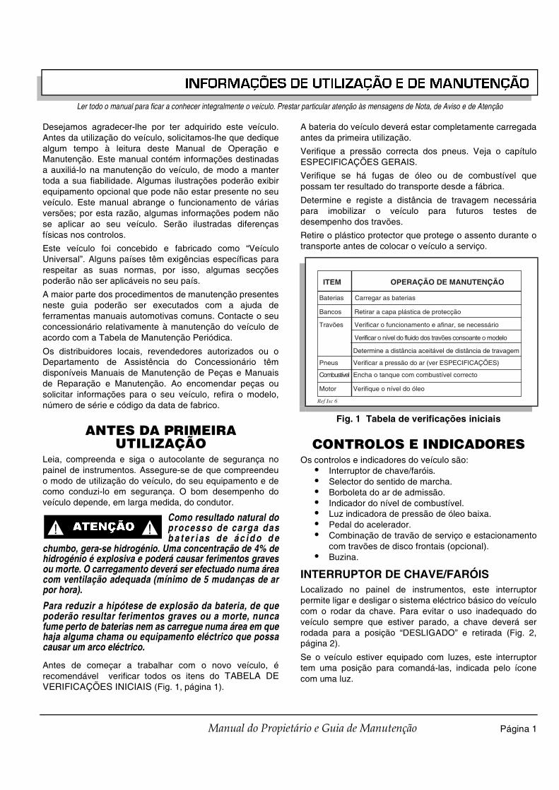
INFORMAÇÕES DE UTILIZAÇÃO E DE MANUTENÇÃO
Página 1Manual do Propietário e Guia de Manutenção
Ler todo o manual para ficar a conhecer integralmente o veículo. Prestar particular atenção às mensagens de Nota, de Aviso e de Atenção
Desejamos agradecer-lhe por ter adquirido este veículo.Antes da utilização do veículo, solicitamos-lhe que dediquealgum tempo à leitura deste Manual de Operação eManutenção. Este manual contém informações destinadasa auxiliá-lo na manutenção do veículo, de modo a mantertoda a sua fiabilidade. Algumas ilustrações poderão exibirequipamento opcional que pode não estar presente no seuveículo. Este manual abrange o funcionamento de váriasversões; por esta razão, algumas informações podem nãose aplicar ao seu veículo. Serão ilustradas diferençasfísicas nos controlos.
Este veículo foi concebido e fabricado como “VeículoUniversal”. Alguns países têm exigências específicas pararespeitar as suas normas, por isso, algumas secçõespoderão não ser aplicáveis no seu país.
A maior parte dos procedimentos de manutenção presentesneste guia poderão ser executados com a ajuda deferramentas manuais automotivas comuns. Contacte o seuconcessionário relativamente à manutenção do veículo deacordo com a Tabela de Manutenção Periódica.
Os distribuidores locais, revendedores autorizados ou oDepartamento de Assistência do Concessionário têmdisponíveis Manuais de Manutenção de Peças e Manuaisde Reparação e Manutenção. Ao encomendar peças ousolicitar informações para o seu veículo, refira o modelo,número de série e código da data de fabrico.
ANTES DA PRIMEIRA UTILIZAÇÃO
Leia, compreenda e siga o autocolante de segurança nopainel de instrumentos. Assegure-se de que compreendeuo modo de utilização do veículo, do seu equipamento e decomo conduzi-lo em segurança. O bom desempenho doveículo depende, em larga medida, do condutor.
Como resultado natural doprocesso de carga dasb a t e r i a s d e á c i d o d e
chumbo, gera-se hidrogénio. Uma concentração de 4% dehidrogénio é explosiva e poderá causar ferimentos gravesou morte. O carregamento deverá ser efectuado numa áreacom ventilação adequada (mínimo de 5 mudanças de arpor hora).
Para reduzir a hipótese de explosão da bateria, de quepoderão resultar ferimentos graves ou a morte, nuncafume perto de baterias nem as carregue numa área em quehaja alguma chama ou equipamento eléctrico que possacausar um arco eléctrico.
Antes de começar a trabalhar com o novo veículo, érecomendável verificar todos os itens do TABELA DEVERIFICAÇÕES INICIAIS (Fig. 1, página 1).
A bateria do veículo deverá estar completamente carregadaantes da primeira utilização.
Verifique a pressão correcta dos pneus. Veja o capítuloESPECIFICAÇÕES GERAIS.
Verifique se há fugas de óleo ou de combustível quepossam ter resultado do transporte desde a fábrica.
Determine e registe a distância de travagem necessáriapara imobilizar o veículo para futuros testes dedesempenho dos travões.
Retire o plástico protector que protege o assento durante otransporte antes de colocar o veículo a serviço.
CONTROLOS E INDICADORESOs controlos e indicadores do veículo são:
• Interruptor de chave/faróis.• Selector do sentido de marcha.• Borboleta do ar de admissão.• Indicador do nível de combustível.• Luz indicadora de pressão de óleo baixa.• Pedal do acelerador.• Combinação de travão de serviço e estacionamento
com travões de disco frontais (opcional).• Buzina.
INTERRUPTOR DE CHAVE/FARÓISLocalizado no painel de instrumentos, este interruptorpermite ligar e desligar o sistema eléctrico básico do veículocom o rodar da chave. Para evitar o uso inadequado doveículo sempre que estiver parado, a chave deverá serrodada para a posição “DESLIGADO” e retirada (Fig. 2,página 2).
Se o veículo estiver equipado com luzes, este interruptortem uma posição para comandá-las, indicada pelo íconecom uma luz.
! !� ATENÇÃO
Fig. 1 Tabela de verificações iniciais
ITEM OPERAÇÃO DE MANUTENÇÃO
Baterias Carregar as baterias
Bancos Retirar a capa plástica de protecção
Travões Verificar o funcionamento e afinar, se necessário
Verificar o nível do fluido dos travões consoante o modelo
Determine a distância aceitável de distância de travagem
Pneus Verificar a pressão do ar (ver ESPECIFICAÇÕES)
Combustível Encha o tanque com combustível correcto
Motor Verifique o nível do óleo
Ref Isc 6

INFORMAÇÕES DE UTILIZAÇÃO E DE MANUTENÇÃO
Página 2 Manual do Propietário e Guia de Manutenção
Ler todo o manual para ficar a conhecer integralmente o veículo. Prestar particular atenção às mensagens de Nota, de Aviso e de Atenção
Se o veículo estiver equipado com acessóriosespeciais, alguns acessórios permanecem
operacionais com o interruptor na posição “DESLIGADO”.
SELECTOR DO SENTIDO DE MARCHAPara reduzir a possibilidade de danos noscomponentes, o veículo deverá estar
completamente parado antes de alterar a posição do selector dosentido de marcha.
Localizada no painel auxiliar do assento, este selectorpermite seleccionar as posições 'F' (Marcha à frente) e 'R'(Marcha atrás) (Fig. 3, página 2). Quando for abandonadotemporariamente, este veículo deve ser deixado na posição’F’.
COMANDO DO AR DE ADMISSÃOO comando de admissão de ar é usado para ajudar o iníciodo arrefecimento (Fig. 4, página 2). Consulte o capítuloINÍCIO DE ARREFECIMENTO para instruções defuncionamento.
INDICADOR DO NÍVEL DE COMBUSTÍVELO indicador do nível de combustível (se equipado) estarásituado no painel de instrumentos (eléctrico) (Fig. 2, página2) ou directamente no depósito de combustível (mecânico).
LUZ INDICADORA DE PRESSÃO DO ÓLEO BAIXAUma luz indicadora da pressão de óleo baixa está situadano painel de instrumentos (Fig. 2, página 2). A luz acende-se quando a pressão do óleo está baixa. Verifique o níveldo óleo. Se o nível do óleo se situar entre as marcasACRESCENTAR e CHEIO na vareta, há um problemamecânico no motor e o veículo não deverá ser conduzido.Contacte o distribuidor local ou uma filial autorizada.
Para evitar danos no motor, não conduza oveículo até que a pressão do óleo esteja
corrigida. Não encha demasiado o motor. Demasiado óleo poderácausar fumos ou a entrada de óleo no protector do filtro de ar.
Se o nível do óleo estiver abaixo da marcaACRESCENTAR na vareta de nível, acrescente óleo paratrazer o óleo para a marca CHEIO Conduza o veículo umpouco e verifique a pressão do óleo. Se a luz do óleo nãoacender, continue a utilizar o veículo.
PEDAL DO ACELERADOR
Qualquer movimento nãointencional do pedal doa c e le r a d o r l i b e r t a rá o
travão de estacionamento e poderá dar or igem àmovimentação do veículo que poderá resultar emferimentos graves ou morte.
Fig. 2 Interruptor de chave/faróis, Indicador luminoso de baixa pressão do óleo e Indicador do
nível de combustível
Fig. 3 Selector do sentido da marcha
OFFOFFONON
FUEL
F
E
Indicador luminosode baixa pressão do óleo
Interruptor dechave/faróis
Indicador do nívelde combustível
Ref Kes 2
NOTA
AVISO
Marchaà frente
Marcha atrás
Ref Dsl 2
Fig. 4 Comando de admissão de ar
Comando deadmissão de arRef Chk 1
AVISO
! !� ATENÇÃO

INFORMAÇÕES DE UTILIZAÇÃO E DE MANUTENÇÃO
Página 3Manual do Propietário e Guia de Manutenção
Ler todo o manual para ficar a conhecer integralmente o veículo. Prestar particular atenção às mensagens de Nota, de Aviso e de Atenção
Com a chave na posição ‘LIGADO’, carregar no pedal doacelerador inicia o motor. O motor pára sempre que retirar opé do pedal (Fig. 5, página 3). Para parar o veículo maisrapidamente, pise o travão de serviço.
Se o interruptor de chave estiver rodado para a posição“LIGADO” e o travão de estacionamento se encontraraplicado, o accionamento inadvertido do pedal doacelerador provoca a libertação do travão deestacionamento e faz o veículo entrar em movimento,podendo causar lesões corporais graves ou morte.
Carregar no pedal do acelerador libertará o travão deestacionamento se este estiver accionado. Estacaracterística garante que o veículo não é conduzidoquando o travão de estacionamento estiver accionado.Carregar no pedal do acelerador não é o melhor métodopara libertar o travão de estacionamento.
O método preferencial de desactivação do travãode estacionamento é carregar na parte inferior
do pedal para garantir a longevidade dos componentes.
COMBINAÇÃO DE TRAVÃO DE SERVIÇO E TRAVÃO DE ESTACIONAMENTOO travão de serviço integra uma característica do travão deestacionamento (Fig. 5, página 3). Para activá-la, empurrepara baixo a secção superior do pedal até que se fixe nolocal. O travão de estacionamento liberta-se quando opedal do travão de serviço for pressionado. Utilize a secçãoinferior do pedal para activar o travão de serviço.
TRAVÕES DE DISCO FRONTAIS OPCIONAISOs travões de disco frontais activam-se quando o pedal dotravão alcança a posição de “estacionar” ou trinco. Carregarno pedal do travão ainda mais, aumentará a eficácia dostravões frontais.
BUZINAA buzina acciona-se empurrando o botão respectivolocalizado no chão, à esquerda do pedal de travão (Fig. 6,página 3).
PLATAFORMA DE CARGA DE AÇO
Para reduzir a possibili-dade de ferimentos gravesou morte leia, compreenda
e siga a etiqueta de perigo afixada na parte da frente docompartimento de carga.
A plataforma de elevação manual é a plataforma padrãopara o veículo. A plataforma pode estar equipada com uminterruptor opcional de elevação eléctrica.
Está afixada uma etiqueta de aviso na sua parte a frente.Consultar o Apêndice A. Para uma utilização segura doveículo, esta etiqueta tem que ser compreendida. Verifiquea capacidade máxima na etiqueta de aviso nocompartimento de carga. No compartimento de carga, estadeve ser posicionada o mais para diante possível,distribuída de forma a que o centro de gravidade não fiquemais elevado do que a altura mencionada, e acondicionada.O desrespeito por estas instruções poderá resultar emferimentos graves, danos ao veículo e/ou causar ocapotamento do veículo. Tenha atenção redobrada aoconduzir um veículo carregado.
Não permita que ninguém viaje no compartimento de carga.
Não conduza o veículo com a caixa de carga levantada oucom a sua porta traseira solta.
Quando estiver a utilizar a elevação eléctrica, certifique-sede que evita recuar até ao extremo de um corte, tal comouma doca de carga ou uma ravina. Um mau cálculo dadistância ou uma superfície instável poderão resultar numaqueda do veículo para trás.
Antes de utilizar a caixa de carga, verifique-se de queninguém está posicionado atrás do veículo.
Fig. 5 Acelerador & travão
Travãode serviço
Acelerador
PARK
Travão deestacionamento
Ref Abc 1
NOTA
Fig. 6 Botão da buzina
HORN
Buzina
PARK
Ref Hor 1
! !� ATENÇÃO

INFORMAÇÕES DE UTILIZAÇÃO E DE MANUTENÇÃO
Página 4 Manual do Propietário e Guia de Manutenção
Ler todo o manual para ficar a conhecer integralmente o veículo. Prestar particular atenção às mensagens de Nota, de Aviso e de Atenção
Nunca encha contentoresde gás no compartimentod e carga do ve ículo . A
descarga de estática podia inflamar o vapor da gasolina ecausar uma explosão.
Coloque sempre o contentor do gás no chão antes de oencher. Nunca encha contentores de gás no compartimentode carga do veículo. Durante o processo de enchimento,gera-se electricidade estática que pode dar ignição aosvapores de gasolina.
FUNCIONAMENTO DA PLATAFORMA DE ELEVAÇÃO MANUAL
Tenha cuidado enquantoestiver a operar a elevaçãomanual. Assegure-se de
que o suporte da plataforma está numa das ranhuras antesda libertação. A libertação descontrolada da plataformapode provocar lesões corporais extremamente graves,como o entalar dos dedos ou de outras partes do corpo.
Para elevar a plataforma de elevação manual, puxe paratrás o manípulo de libertação do trinco, exactamente atrásdo banco do condutor (Fig. 7, página 4). Eleve a plataformautilizando o manípulo no lado da plataforma.
Eleve a plataforma de carga para uma posição segura everifique a estabilidade antes de libertar o manípulo daplataforma (Fig. 8, página 4).
FUNCIONAMENTO DA PLATAFORMA DE ELEVAÇÃO ELÉCTRICA
T e n h a m u i t o c u i d a d oenquanto estiver a operar aplataforma de e levação
eléctrica para assegurar que a roupa não é puxada duranteos procedimentos de elevação ou abaixamento. A quedadescontrolada da plataforma pode provocar lesõescorporais extremamente graves, como o entalamento dosdedos ou de outras partes do corpo.
O interruptor do elevador eléctrico está do lado do condutordo painel de assentos dianteiro (Fig. 9, página 4). Mova ointerruptor para cima para levantar a plataforma vazia epara baixo para baixar a plataforma vazia.
PLATAFORMA DE CARGA DE PLÁSTICO
A plataforma de elevação manual é a plataforma padrãopara o veículo. A plataforma pode estar equipada com uminterruptor opcional de elevação eléctrica.
O desrespeito por estasinstruções poderá resultare m fe r im en tos gr av es ,
danos no veículo e/ou provocar o capotar do veículo.Opere o ve ículo com consciência da carga. Le ia ,compreenda e siga o autocolante de Perigo afixado naparte frontal da plataforma de carga. Não permita que ninguém viaje na plataforma.Antes de operar a plataforma de carga, certifique-se deque não está ninguém atrás do veículo.Uma etiqueta de plataforma de carga está afixada nointerior frontal da plataforma (consulte o Apêndice A). Parauma utilização segura, esta etiqueta tem que sercompreendida e observada. Verifique a capacidade naetiqueta no compartimento de carga. Esta deve serposicionada o mais para diante possível, distribuída deforma a que o centro de gravidade não fique mais elevadodo que a altura mencionada, e apertada para baixo. Odesrespeito por estas instruções poderá resultar emferimentos, danos no veículo e/ou provocar o capotar.Opere o veículo com consciência da carga.
Fig. 7 Trinco da plataforma manual
Fig. 8 Barra de suporte da plataforma
! !� ATENÇÃO
! !� ATENÇÃO
Ref Mbl 3
Frente do veículo
Trinco do compartimentode carga manualDesloque para trás para a liberação
Ref Bpr 1
Fig. 9 Interruptor do elevador eléctrico
! !� ATENÇÃO
Elevar
Baixar
Ref Lbs 1
! !� ATENÇÃO

INFORMAÇÕES DE UTILIZAÇÃO E DE MANUTENÇÃO
Página 5Manual do Propietário e Guia de Manutenção
Ler todo o manual para ficar a conhecer integralmente o veículo. Prestar particular atenção às mensagens de Nota, de Aviso e de Atenção
Não permita que ninguém viaje na plataforma.
Não conduza o veículo com a caixa de carga levantada oucom a sua porta traseira solta.
Quando estiver a utilizar a elevação eléctrica, certifique-sede que evita recuar até ao extremo de um corte, tal comouma doca de carga ou uma ravina. Um mau cálculo dadistância ou uma superfície instável poderão resultar numaqueda do veículo para trás.
Antes de operar a plataforma de carga, certifique-se de quenão está ninguém atrás do veículo.
Nunca encha contentoresde gás no compartimentode c arga do ve ículo . A
descarga de estática podia inflamar o vapor da gasolina ecausar uma explosão.
Coloque sempre o contentor do gás no chão antes de oencher. Nunca encha contentores de gás no compartimentode carga do veículo. Durante o processo de enchimento,gera-se electricidade estática que pode dar ignição aosvapores de gasolina.
FUNCIONAMENTO DA PLATAFORMA DE ELEVAÇÃO MANUAL
T e n h a m u i t o c u i d a d oenquanto estiver a operar aplataforma de e levação
manual para assegurar que não é libertada durante osprocedimentos de elevação ou abaixamento. A libertaçãodescontrolada da plataforma pode provocar lesõescorporais extremamente graves, como o entalar dos dedosou de outras partes do corpo.
Para elevar a plataforma de elevação manual, puxe paratrás o manípulo de libertação do trinco, exactamente atrásdo banco do condutor (Fig. 10, página 5). Eleve aplataforma utilizando o manípulo no lado da plataforma.
O suporte do gás irá ajudar a levantar a plataforma decarga vazia e a manter a plataforma levantada (Fig. 11,página 5).
Com o passar do tempo, o suporte do gás podepermitir que a plataforma de carga baixe
lentamente. Se esta condição for evidente, é necessária asubstituição do suporte do gás.
Para descer a plataforma de elevação manual, pegue nomanípulo da plataforma e baixe-a para a posição dedescanso. Certifique-se de que as mãos não sãoapanhadas pela plataforma.
FUNCIONAMENTO DO TAIPAL TRASEIROPara abrir o taipal traseiro, eleve-o a direito com um impulsoríspido para sair da posição fechada e pivot para fora paraposição aberta. Para retirar o taipal traseiro, retire os caboslaterais da plataforma de carga e abra o taipal traseiro atéestar completamente em baixo, mova o painel do taipaltraseiro para cima para o retirar dos pinos e da plataformade carga. Torne a montar na ordem inversa.
FUNCIONAMENTO DA PLATAFORMA DE ELEVAÇÃO ELÉCTRICA
T e n h a m u i t o c u i d a d oenquanto estiver a operar aplataforma de e levação
eléctrica para assegurar que a roupa não é puxada duranteos procedimentos de elevação ou abaixamento. A quedadescontrolada da plataforma pode provocar lesõescorporais extremamente graves, como o entalamento dosdedos ou de outras partes do corpo.
O interruptor do elevador eléctrico está localizado do ladodo condutor do painel de assentos dianteiro (Fig. 12, página6). Mova o interruptor de alavanca para cima para levantara plataforma vazia e para baixo para baixar a plataformavazia.
Fig. 10 Trinco da plataforma manual
! !� ATENÇÃO
! !� ATENÇÃO
Ref Mbl 3
Frente do veículo
Trinco do compartimentode carga manualDesloque para trás para a liberação
Fig. 11 Suporte do gás
Ref Gss 1
NOTA
! !� ATENÇÃO

INFORMAÇÕES DE UTILIZAÇÃO E DE MANUTENÇÃO
Página 6 Manual do Propietário e Guia de Manutenção
Ler todo o manual para ficar a conhecer integralmente o veículo. Prestar particular atenção às mensagens de Nota, de Aviso e de Atenção
UTILILIZAÇÃO DO VEÍCULOA utilização inadequada do veículo ou a falta demanutenção adequada poderão resultar em
danos ou numa redução do desempenho.
Leia e compreenda os avisos seguintes antes de tentarconduzir o veículo.
Para reduzir a possibili-dade de ferimentos gravesou morte resultantes da
perda de controlo do veículo, deverão respeitar-se osseguintes avisos:
Ao conduzir o veículo, tenha em consideração oestado do piso, as condições de tráfego e os factoresambientais que afectam o terreno e a capacidade decontrolar o veículo.Em pisos irregulares ou em mau estado (piso solto,relva molhada, gravilha, etc.), conduzir com cuidadoredobrado e a velocidades reduzidas.Permanecer sempre nas áreas designadas do campo eevitar os percursos com inclinações acentuadas.Mantenha uma velocidade segura ao conduzir emdescidas. Utilize o travão de serviço ao descer umterreno inclinado. Uma paragem ou mudança dedirecção bruscas poderão resultar em perda decontrolo.Reduzir a velocidade antes e durante as curvas. Todasas curvas devem ser efectuadas a velocidadesmoderadas.Não conduza o veículo por terrenos com mais de 14°de inclinação (25% desnível).
Para reduzir a possibili-dade de ferimentos gravesou morte resultantes da
perda de controlo do veículo, deverão respeitarse osseguintes avisos:
Consulte as ESPECIFICAÇÕES GERAIS para saber alotação do veículo.
P is a nd o o p e d al d o a ce l er ad o r , o t ra vã o d eestacionamento é desactivado e poderá causar umamovimentação inadvertida do veículo. Sempre que oveículo estiver estacionado, rode a chave para aposição ‘DESLIGADO’.Para evitar qualquer movimentação inadvertida doveículo, sempre que este estiver estacionado, accioneo travão de estacionamento, desloque o selector dosentido de marcha para a posição Marcha à Frente,rode a chave para a posição ‘DESLIGADO’ e retire-a.Assegure-se de que o selector do sentido de marchaestá na posição correcta antes colocar o veículo emmarcha.Imobilize totalmente o veículo antes de alterar aposição do selector do sentido de marcha.Não desengrene o veículo em movimento.Verifique a área atrás do veículo antes de fazermarcha-atrás.Todos os ocupantes deverão permanecer sentados.Mantenha a totalidade do corpo dentro do veículo e aguarde enquanto o veículo estiver em movimento.
RODAGEMVerifique se há fugas de óleo ou de combustível quepossam ter resultado do transporte desde a fábrica. Evitearranques à velocidade máxima e quaisquer aceleraçõesrápidas até que o motor tenha atingido a temperatura ideal.
Todos os motores consomem mais óleo do que o normaldurante as primeiras horas de utilização. Como todas aspeças móveis internas têm que ser rodadas, o consumo deóleo deverá reduzir gradualmente até que o consumoestabiliza.
Verifique o nível do óleo de acordo com a Tabela Periódicade Manutenção. Acrescente óleo se o nível indicar queprecisa (Fig. 21, página 15).
Não encha demasiado o motor. Demasiado óleopoderá causar fumos ou a entrada de óleo no
protector do filtro de ar.
Tanto o tampão do oleo como a vareta deverãoser recolocados no seu lugar antes de utilizar o
motor. Qualquer falha nesse ponto resultará numacontaminação do óleo e/ou o mesmo ser espalhado pelocompartimento do motor.
O óleo deverá ser mudado de acordo com a TabelaPeriódica de Manutenção enquanto o motor estiver quente.Consulte o capítulo SERVIÇO E MANUTENÇÃO parasaber como verificar do nível do óleo e como mudar o óleo.
Fig. 12 Interruptor do elevador eléctrico
Elevar
Baixar
Ref Lbs 1
AVISO
! !� ATENÇÃO
! !� ATENÇÃO
AVISO
NOTA

INFORMAÇÕES DE UTILIZAÇÃO E DE MANUTENÇÃO
Página 7Manual do Propietário e Guia de Manutenção
Ler todo o manual para ficar a conhecer integralmente o veículo. Prestar particular atenção às mensagens de Nota, de Aviso e de Atenção
ARRANQUE A FRIOO arranque de um motor frio pode requerer a utilização docomando da borboleta do ar de admissão. Accionar oacelerador cerca de 2,5 cm ou até o motor de arranquecomeçar a funcionar. Puxar o botão de comando daborboleta do ar de admissão. Acelerar o motor lentamente eempurrar o botão de comando da borboleta para dentroapós o funcionamento do motor sem oscilações develocidade.
Não accionar continuamente o motor dearranque durante mais de 10 segundos. Esperar
30 segundos antes de efectuar a segunda tentativa de arranque. Seo motor não arrancar à terceira tentativa, desligar o interruptor daignição, aplicar o travão de estacionamento e determinar a causa daanomalia.
Se o veículo tiver estado em funcionamento e o motor nãoarrancar num intervalo de 10 segundos, utilizar o comandoda borboleta do ar de admissão.
INÍCIO DE MARCHA E CONDUÇÃO
Para reduzir a possibi li-dade de deslizamento parat r á s , d e q u e p o d e r ã o
resultar ferimentos graves ou danos ao veículo, não liberteo travão de serviço até que o motor esteja a trabalhar.
Para utilizar o veículo:• Accione o travão de serviço, introduza a chave na
sua ranhura e rode-a para a posição ‘LIGADO”. • Desloque o selector do sentido de marcha para a
posição desejada.• Liberte o travão de estacionamento pressionando o
travão de serviço até que o travão deestacionamento se desactive.
• Pressione levemente o pedal do acelerador parainiciar o motor. Liberte o travão de serviço quando omotor começar a trabalhar.
• Quando o pedal do acelerador for libertado, o motorpára. Para parar o veículo mais rapidamente, pise opedal do travão de serviço.
Quando o selector do sentido de marcha estiverna marcha-atrás, um sinal de aviso soará para
indicar que o veículo está preparado para marcha-atrás.
INICIAR A MARCHA NUMA POSIÇÃO INCLINADA
Para reduzir a possibili-dade de deslizamento parat r á s , d e q u e p o d e r ã o
resultar ferimentos graves ou danos ao veículo, não liberteo travão de serviço até que o motor esteja a trabalhar.
Não manter o veículo imobilizado em pisosinclinados, utilizando o acelerador e o motor.
Este procedimento danifica o motor e provoca o desgasteprematuro e excessivo nos componentes dos órgãos datransmissão.
Para reduzir a possibilidade de danos permanentes aosistema de tracção, é importante evitar um deslizamentoexcessivo para trás quando se inicia a marcha numaposição inclinada.
Coloque o pé esquerdo no travão de serviço e liberte otravão de estacionamento. Pressione o acelerador com opé direito e liberte o travão de serviço, levantando o péesquerdo.
CIRCULAÇÃO COM O MOTOR DESENGRENADO OU DESLIGADO
Para reduzir a possibili-dade de ferimentos graveso u m o r t e d e r i v a d o s à
circulação com o motor desengrenado ou desligado acimados limites de velocidade recomendados, controle avelocidade com o travão de serviço.
Em inclinações acentuadas, é possível ao veículo avançarem ponto-morto a uma velocidade maior do que a que podeser atingida numa superfície plana. Para evitar a perda decontrolo do veículo e danos severos na transmissão, avelocidade deverá ser limitada ao máximo aconselhadopara pisos planos (ver ESPECIFICAÇÕES GERAIS). Limitea velocidade com o travão de serviço.
COMBUSTÍVELPara reduzir a possibili-dade de ferimentos graveso u m o r t e d e r i v a d a a
manuseamento inadequado do combustível:Não fume perto do depósito de combustível.Não abasteça o veículo perto de chamas ou elementoseléctricos que possam produzir faíscas.Manuseie a gasolina em áreas bem ventiladas.Use sempre protecção ocular para se proteger ded e r r a m e s d e c o m b u s t í v e l e d e v a p o r e s d ecombustível.
Fig. 13 Verificar o nível do óleo na vareta de nível
Nível máximo do óleoNÃO ULTRAPASSAR
Limite segurode funcionamento
Acresc. Cheio
Ref Dsk 1
AVISO
! !� ATENÇÃO
NOTA
! !� ATENÇÃO
AVISO
! !� ATENÇÃO
! !� ATENÇÃO

INFORMAÇÕES DE UTILIZAÇÃO E DE MANUTENÇÃO
Página 8 Manual do Propietário e Guia de Manutenção
Ler todo o manual para ficar a conhecer integralmente o veículo. Prestar particular atenção às mensagens de Nota, de Aviso e de Atenção
Perm i ta sem pre um espa ço ade quad o para aexpansão da gasolina. Deixe um espaço mínimo de 2,5c m a b a i x o d o f u n d o d o g a r g a l o d a p i s t o l aabastecedora.Verifique se a tampa do depósito de combustível eoutros componentes têm fugas ou deteriorações quepossam dar azo a situações perigosas.
O depósito de combustível está situado sob o assento nolado do passageiro do veículo (Fig. 14, página 8). Encha odepósito com gasolina de automóvel fresca, limpa (Fig. 42,página 25). A utilização a elevada altitude ou em condiçõesde carga pesada podem beneficiar de uma gasolina comoctanas mais elevadas.
Não use gasolina que contenha Metanol.
Alguns combustíveis, chamados gasolinasoxigenadas ou reformuladas, são gasolinas
misturadas com álcoois ou éteres. Quantidades excessivas destasmisturas podem danificar o sistema de combustível ou dar origem aproblemas de desempenho. Se ocorrerem alguns sintomasindesejáveis de utilização, use uma gasolina com uma percentageminferior de álcool ou éter.
BATERIAA utilização excessiva de acessórios eléctricopoderá enfraquecer a bateria e deixá-la com
pouca carga para colocar o veículo a trabalhar.
O veículo faz uso de uma combinação motor de arranque/alternador para iniciar o motor e para carregar a bateria. Omotor não fica em ponto-morto; por isso, a bateria não podeser carregada com o veículo parado. Não utilizeexcessivamente acessórios (como as luzes, o rádio, oguincho, etc.) enquanto o veículo estiver parado.
O alternador apenas debita 35 amps; por isso, a utilizaçãode todos os acessórios eléctricos poderá resultar nadescarga da bateria, mesmo com o motor e o alternador atrabalhar. A descarga da bateria é conhecida como ciclocompleto. A bateria não é um modelo de ciclo completo; éuma bateria de arranque. Múltiplos ciclos completos dabateria resultarão na falha prematura da mesma.
Se a bateria do veículo se descarregou, deverá serrecarregada com um carregador de 12 Volt que debite 10amps ou menos e de acordo com todas as instruçõesfornecidas pelo fabricante da bateria.
ETIQUETAS E PICTOGRAMASOs veículos podem ser etiquetados com pictogramas comometido conveniente de informação ou de aviso. O ApêndiceA ilustra e explica os pictogramas que podem surgir noveículo. Nem todos os pictogramas exibidos no Apêndice Apoderão constar no seu veículo.
CAPOTA SOLAR E PÁRA-BRISASO pára-brisas não ofereceprotecção contra objectosem queda ou voadores.
A capota não oferece protecção contra ramos de árvores ocontra objectos voadores nem .
Para impedir os danos ao veículo, não prendasol suportes superiores e para estar nos painéis
do corpo.
A capota solar e o pára-brisas proporcionam algumaprotecção contra o sol e o vento; contudo, não protegemtotalmente o condutor e os ocupantes da viatura em casode chuva. Este veículo não está equipado com cintos desegurança e a capota não foi concebida para proporcionarprotecção em caso de capotamento. Em acréscimo, acapota não oferece protecção contra objectos que caiamnem o pára-brisas oferece protecção contra objectosvoadores nem ramos de árvores. Em circulação, mantenhaos braços e as pernas dentro do veículo.
TOMADA DE 12 VA utilização excessiva desses acessóriospoderá enfraquecer a bateria e deixá-la com
pouca carga para colocar o veículo a trabalhar.
Uma tomada de 12 V, calculada a 15 amperes, está situadaà esquerda do interruptor de chave/luz (Fig. 15, página 8).Ela fornece energia a acessórios equipados com uma fichade 12 V.
Fig. 14 Abastecimento
AVISO
Min.2,5 cm
Combustível
Ref Ftl 1
AVISO
Fig. 15 Tomada de 12 V
! !� ATENÇÃO
AVISO
AVISO
Tomada de 12 V
ONOFF
FUEL
FE
Ref Pow 1

INFORMAÇÕES DE UTILIZAÇÃO E DE MANUTENÇÃO
Página 9Manual do Propietário e Guia de Manutenção
Ler todo o manual para ficar a conhecer integralmente o veículo. Prestar particular atenção às mensagens de Nota, de Aviso e de Atenção
REBOCAR UM ATRELADOO veículo está equipado com um receptor para uma bola dereboque normalizada de 1 7/8" . O atrelado e a sua carganão deverão exceder os 227 kg e não deverá ser acopladauma lingueta com mais de 23 kg à bola. Lembre-se que acapacidade total do veículo, condutor, passageiro,conteúdo do compartimento de carga e acessórios deverãoser reduzidos para compensar o atrelado e a sua carga.
O ângulo de deslocação do atrelado deverá ser limitadopela bola e pela lingueta. O atrelado não deverá serutilizado em trilhos de terra batida ou sobre troncos, rochas,buracos, etc.
Não instalar cestos ou acessórios usando no receptor deengate (na parte da frente ou na parte de trás). Quaisquermodificações alteram o desempenho do veículo, causarcapotamento e que poderão resultar danos ao veículo.
CUIDADOS E LIMPEZA DO VEÍCULO
LIMPEZA DO VEÍCULO
Para reduzir a possibi li-dade de ferimentos gravesou danos no veículo, leia e
compreenda as instruções fornecidas pelo fabricante dabomba de lavagem à pressão.
Quando lavar o veículo com uma bomba delavagem à pressão, não ultrapasse uma pressão
de 4825 kPa. Para reduzir a possibilidade de danos cosméticos, nãouse solventes abrasivos ou reagentes para limpeza das partes emplástico.
É importante que se utilizem as técnicas e os materiaisadequados. A utilização de uma pressão excessiva de águapode causar ferimentos graves ao seu utilizador ou apessoas que se encontrem nas imediações, danos aosassentos, aos plásticos, ao material dos assentos, aoacabamento da carroçaria ou ao sistema eléctrico. Nãoultrapasse uma pressão de 4825 kPa ao lavar o exterior doveículo.
Limpe o pára-brisas com água abundante e um pano limpo.Os pequenos riscos podem ser removidos com uma pastade polimento para plásticos ou um produto Plexus® paralimpeza de plásticos, disponível no departamento de peças.
A limpeza do vinil dos assentos e dos acabamentos emplástico ou em borracha pode ser feita com uma solução desabão suave aplicado com uma esponja ou uma escovasuave e a secagem com um pano felpudo.
A remoção de óleo, alcatrão, asfalto, graxa de sapatos, etc,pode ser feita com um produto comercial para limpeza devinil/borracha.
As superfícies pintadas do veículo dão-lhe uma aparênciaatraente e uma protecção duradoura. Para preservar assuperfícies pintadas são necessárias lavagens frequentescom água tépida ou fria e um detergente suave.
A aparência e a durabilidade das superfícies pintadaspoderão ser mantidas através da limpeza e polimentoocasionais dessas superfícies com produtos não abrasivospara acabamentos em automóveis.
Materiais corrosivos utilizados, como fertilizantes ou paracontrolo de poeiras, podem acumular-se na parte de baixodo veículo. Estes materiais dão origem a corrosão daspeças situadas na parte de baixo e devem ser limposocasionalmente com água. Limpe meticulosamentequaisquer áreas em que possam acumular lama ou detritos.Os sedimentos acumulados em áreas fechadas deverãoser soltos para facilitar a sua remoção, tomando cuidadopara não ferir ou danificar a pintura.
Se o motor não se iniciar ou trabalhar de formairregular após uma lavagem, retire os cabos das
velas (puxando-os pelos protectores dos contactos; nuncapelos cabos). Seque todos os contactores com ar forçado.Reistale os cabos.
PRODUTOS PARA CUIDAR DO VEÍCULOPara ajudar a manter o veículo, há vários produtosdisponíveis nos revendedores locais, distribuidoresautorizados ou no Departamento de Peças doConcessionário.
• Tinta para retoques especialmente formulada paracorresponder às cores do veículo para utilizar emcarroçarias tanto de metal como de plástico moldado(N/P 28140-G** e 28432-G**).
• Protector de Bateria formulado para formar umacamada de longa duração, flexível, não pegajosa,seca, que não estalará, esfolará ou desfará sobreuma larga amplitude térmica (N/P 75500-G01).
• Massa Branca Lubrificante de Lítio para lubrificaçãoe protecção das áreas em que as manchas ou a faltade pintura representam um problema, ou em áreasde grande variação de temperatura (N/P 75502-G01).
• Penetrante/Lubrificante, um produto 4 em 1 quepenetra nas peças apanhadas, lubrifica deixandouma película lubrificante leve, reduz a corrosãoaderindo a superfícies molhadas ou secas e deslocaa humidade, vedando contra um futuro retorno dahumidade (N/P 75503-G01).
• Produto de limpeza e Desengordurante Multi-funções que contém solventes naturais e ecológicos(N/P 75504-G01).
! !� ATENÇÃO
AVISO
NOTA

INFORMAÇÕES DE UTILIZAÇÃO E DE MANUTENÇÃO
Página 10 Manual do Propietário e Guia de Manutenção
Ler todo o manual para ficar a conhecer integralmente o veículo. Prestar particular atenção às mensagens de Nota, de Aviso e de Atenção
• Produto de limpeza de mãos multi-usos, produtoindustrial de limpeza forte, sem solventes abrasivos,que retira suavemente a gordura das mãos. Podeser usado com ou sem água (N/P 75505-G01).
• Líquido de limpeza de Baterias que neutraliza osácidos da bateria e dissolve a corrosão dosterminais e pode ser lavado com água (N/P 75506-G01).
• Produto de limpeza bio degradável que destrói agordura para ser facilmente limpa ou lavada (N/P75507-G01).
• Uma embalagem de várias amostras que inclui latasde spray de 118 ml de protector de baterias,lubrificante, massa branca lubrificante e produto delimpeza do carburador e do sistema de admissão dear (N/P 75508-G01).
• Produto de limpeza de plásticos e polidor Plexus®
retira os mais pequenos riscos do pára-brisas (N/P28433-G**).
REPARAÇÃOELEVAÇÃO DO VEÍCULOFerramentas necessárias Qtd. Necessária
Macaco ............................................................................ 1Suportes de elevação ...................................................... 4Calços.............................................................................. 4
Algumas operações de manutenção podem exigir aelevação das rodas dianteiras, traseiras ou do veículo.
Para reduzir a possibili-dade de ferimentos gravesou morte provocados pela
queda de um veículo do seu macaco de elevação:Assegure-se de que o veículo está numa superfíciefirme e nivelada.Nunca se coloque sob um veículo elevado por ummacaco.Use apoios de elevação e teste a estabilidade doveículo nos apoios.Coloque sempre calços nas rodas dianteira e traseiraque não estão a ser elevadas.Tenha a máxima precaução uma vez que o veículo ficaextremamente instável durante o processo deelevação.
Para elevar o veículo, colocar o macaco e oscepos apenas nos locais indicados.
Para elevar a totalidade do veículo, calçar, à frente e atrás,as rodas dianteiras (Fig. 16, página 10). Centrar o macacosob a travessa traseira do chassis. Elevar o veículo ecolocar um cepo sob a extremidade exterior de cada mangade eixo traseira.
Baixar o macaco e verificar a estabilidade do veículo sobreos dois cepos.
Coloque o macaco no centro do eixo dianteiro. Elevar oveículo e colocar um cepo sob a travessa do chassis,conforme indicado na figura.
Baixar o macaco e verificar a estabilidade do veículo nosquatro cepos.
Se apenas a parte traseira ou dianteira do veículo tiver queser elevada, colocar os calços à frente e atrás de cada rodaem contacto com o solo, de forma a estabilizar o veículo.
Baixe o veículo invertendo a sequência de elevação.
RODAS E PNEUMÁTICOS
Reparação de pneusFerramentas necessárias Qtd. Necessária
Chave de porcas, 3/4" ..................................................... 1Chave de caixa de impacto, 3/4", cubo de 1/2" ............... 1Chave de impacto, cubo de 1/2"...................................... 1Chave de impacto, cubo de 1/2"...................................... 1
A explosão de um pneupode causar ferimentosgraves ou morte. Nunca
exceda a classificação da pressão indicada na parte lateraldo pneu.
! !� ATENÇÃO
AVISO
Fig. 16 Elevação do veículo
Ref Liv 1 Vista da parte de baixo do veículo
Centro doeixo dianteiro
Porção planada estrutura
Terminal exteriordo eixo traseiro
! !� ATENÇÃO

INFORMAÇÕES DE UTILIZAÇÃO E DE MANUTENÇÃO
Página 11Manual do Propietário e Guia de Manutenção
Ler todo o manual para ficar a conhecer integralmente o veículo. Prestar particular atenção às mensagens de Nota, de Aviso e de Atenção
Para reduzir a possibilidade de explosão de um pneu,encher o pneu com uma reduzida pressão de araplicada intermitentemente para assentar o talão dopneu na jante. Devido ao baixo volume dos pneuspequenos, o sobre-enchimento pode ocorrer emsegundos. Nunca ultrapasse as recomendações dofabricante ao assentar o pneu na jante. Proteja a carae os olhos do ar que escape a válvula quando retirar aparte interior da válvula.Para reduzir a possibilidade de ferimentos causadospela quebra de chaves de caixa quando retirar rodas,utilize apenas chaves concebidas para impacto.Tenha cuidado ao encher pneus. O sobre-enchimentopode originar a separação do pneu da jante ou causara explosão do pneu, e pode causar ferimentos graves.
Tenha cuidado ao encher pneus. Devido ao baixo volumedos pneus pequenos, o sobre-enchimento pode ocorrer emsegundos. O sobre-enchimento pode originar a separaçãodo pneu da jante ou causar a explosão do pneu.
A pressão de enchimento deve depender das condições doterreno. Ver nas ESPECIFICAÇÕES GERAIS a pressãodos pneus recomendada. Em utilização exterior em áreasmaioritariamente relvadas, considerar os pontos seguintes.Em terrenos relvados duros, recomenda-se uma pressãode enchimento ligeiramente mais elevada. Em pisos muitomacios, uma pressão de enchimento mais baixa impede amarcação da relva pelos pneus. Em veículos utilizados empisos asfaltados ou duros, recomenda-se uma pressão deenchimento mais elevada, mas sem a pressão ser superiorà recomendada na parede lateral do pneu. Os quatropneus deverão ter a mesma pressão para um óptimodesempenho. Recoloque a tampa da válvula apósverificação ou enchimento.
O veículo está equipado com pneus de baixa pressão semcâmara de ar, montados em jantes monobloco.Normalmente, o modo mais económico de reparar um pneufurado, é utilizar um remendo normal para pneus.
As ferramentas para remendar o furo e osremendos encontram-se disponíveis na maioria
das lojas de peças para automóveis e têm a vantagem de nãoser necessário retirar o pneu da roda.
Se o pneu estiver furado, retirar a roda e encher o pneucom a pressão máxima recomendada. Mergulhar o pneuem água para localizar a fuga; marcar o local com giz.Aplicar o remendo, de acordo com as especificações dofabricante.
Para reduzir a possibi li-dade de ferimentos graves,a s s e g u r e - s e d e q u e a
máquina de montagem/desmontagem está firmementefixada ao chão. Use equipamento de protecção namontagem/ desmontagem de pneus.
Se o pneu tiver que ser retirado ou montado, observar asrecomendações do fabricante da máquina para mudarpneus, de modo a minimizar o risco de lesões corporais.
Instalação das rodasPara reduzir a possibilidade de danos aoscomponentes, não aperte as porcas com uma
força superior a 115 Nm.
É importante seguir o aperto em “sequênciatransversal” quando apertar as porcas. Este
procedimento garante o assento perfeito da jante no cubo daroda.
Com o pipo da válvula virado para fora, fixe a roda no cubocom a ajuda das porcas. Aperte as porcas com os dedosseguindo uma sequência transversal (Fig. 17, página 11) .Aperte as porcas com uma pressão de 70-115 Nm emintervalos progressivos de 30 Nm, seguindo a sequênciatransversal.
SUBSTITUIÇÃO DE LÂMPADAS DOS FARÓIS
Para impedir a fusão prematura das lâmpadas,não tocar nas lâmpadas novas directamente
com os dedos. Utilizar um pano limpo e seco ou um toalhete depapel para manusear a parte de vidro da lâmpada.
Para veículos com a iluminação montada no capot, localizedois parafusos no lado posterior do capot que suporta ailuminação (Fig. 18, página 12). Retire os parafusos, puxe ofarol para fora e desligue os fios. Ligue os fios ao novo farol,instale-o no suporte e fixe-o com os parafusosanteriormente removidos.
Para substituir a lâmpada da luz indicadora de mudança dedirecção, apoie o compartimento do indicador de mudançade direcção do lado posterior do capot enquanto removedois parafusos que segurem a lente. Instale a novalâmpada e torne a colocar os parafusos.
Para substituir a lâmpada do taipal e do travão, deslize amoldura de borracha em torno da extremidade da luztraseira e retire a lente. Instale a nova lâmpada e torne acolocar a lente.
NOTA
! !� ATENÇÃO
Fig. 17 Instalação das rodas
AVISO
NOTA
O modelo do pneupode variar
1
2
3
4
'Sequência transversal'
Ref Whi 1
AVISO

INFORMAÇÕES DE UTILIZAÇÃO E DE MANUTENÇÃO
Página 12 Manual do Propietário e Guia de Manutenção
Ler todo o manual para ficar a conhecer integralmente o veículo. Prestar particular atenção às mensagens de Nota, de Aviso e de Atenção
SUBSTITUIÇÃO DE FUSÍVEISPara substituir fusíveis, localize o painel de fusíveis debaixodo assento do condutor. Retire o fusível velho e substitua-opor um novo fusível do tipo para automóvel. Osdistribuidores locais, revendedores autorizados ou oDepartamento de Assistência do Concessionário têmdisponíveis lâmpadas dianteira, traseiras e fusíveis desubstituição.
VEÍCULO COM A BATERIA DESCARREGADA
Para reduzir a possibili-dade de ferimentos gravesou morte resultantes da
movimentação inadvertida, nunca tente fazer pegar oveículo ‘de empurrão’.
Este veículo está equipado com um motor de arranque/alternador que não tem ponto-morto. Ao iniciar o motor, omotor de arranque/alternador funciona como motor dearranque e, em funcionamento, funciona como alternador.
Com os pequenos percursos associados ao tipo desteveículo, o alternador é mais do que adequado para mantero nível de carga da bateria. O alternador não foi concebidopara carregar uma bateria descarregada.
Quando o motor arranca, a embraiagem engata e provoca oandamento do veículo, o que torna o ‘empurrão’ perigoso epouco prático.
Se a bateria do veículo se descarregou, deverá serrecarregada com um carregador de 12 V que debite10 amps ou menos. Leia e compreenda todas as instruçõesfornecidas pelo fabricante da bateria.
TRANSPORTE DO VEÍCULOREBOQUE
E s t e v e í c u l o n ã o f o ic o n c e b i d o p a r a s e rrebocado.
Recomenda-se o transporte do veículo num atrelado, numcamião com compartimento de carga plano ou noutrotransporte adequado.
BLOQUEIO DE PONTO MORTOPara evitar que as rodas girem durante as operações deserviço, o travamento neutro está colocado no eixo traseiro.
Para utilizá-lo:
Gire a chave para a posição “DESLIGADO” e levante obanco. Retire e gire o pino de fechamento neutro punho demodo que a parcela do punho seja ao lado da came doseletor do sentido (Fig. 20, página 13). desloque o selectordo sentido de marcha para a posição entre ‘F’ e ‘R’. Duranteesse movimento, o pino agarrará no furo no suporte demontagem do seletor do sentido que impede algunsmovemen. Quando atingir essa posição, o selector dedirecção mantém-se fixado na posição de ponto-morto.Para destravar o seletor do sentido, retire o pino defechamento neutro punho e gire-o até a parcela dos ajustesdo punho no furo na came do seletor do sentido.
Fig. 18 Substituição das lâmpadas do farol dianteiro e do indicador de mudança de direcção
Fig. 19 Substituição das lâmpadas das luzes de presença traseiras e das luzes de travão
Lâmpadade Iluminação
Lâmpada indicadora demudança de direcção
Compartimentodo indicadorde mudançade direcção
Interior docapot
Ref Hdr 2
Pára-choquestraseiro
Luz traseira depresença e de travão
Enrole o fixadorde borracha emredor da carroçaria
Ref Tlr 2
! !� ATENÇÃO
! !� ATENÇÃO

INFORMAÇÕES DE UTILIZAÇÃO E DE MANUTENÇÃO
Página 13Manual do Propietário e Guia de Manutenção
Ler todo o manual para ficar a conhecer integralmente o veículo. Prestar particular atenção às mensagens de Nota, de Aviso e de Atenção
TRANSPORTE DO VEÍCULO SOBRE UM CAMIÃO
Para reduzir a possibi li-dade de ferimentos graveso u m o rt e e n q u a n to s e
transporta o veículo:Acondicione bem o veículo e os seus acessórios.Nunca viaje num veículo a ser transportado.Retire sempre o pára-brisas antes do transporte. A velocidade máxima com a capota instalada é de80 km/h.
Se o veículo for transportado a velocidades de auto-estrada, a capota tem que ser retirada e as almofadas dosassentos têm que ser presas. Quando o veículo fortransportado abaixo da velocidade de auto-estrada,verifique se há folgas nos acessórios e fendas nos pontosde fixação da capota. Retire sempre o pára-brisas durante otransporte. Verifique sempre se o veículo e os acessóriosestão devidamente acondicionados antes do transporte. Atara do reboque ou do camião transportador deveráexceder o peso do veículo (ver o peso do veículo nasESPECIFICAÇÕES GERAIS e da carga). Bloqueie o travãode estacionamento e prenda o veículo usando amarraçõesde aperto por roquete.
MANUTENÇÃO DE ROTINAPara reduzir a possibili-dade de ferimentos graveso u m o r t e d e r i v a d a a
procedimentos inadequados de manutenção:Não tente quaisquer procedimentos de manutençãoan te s de le r e co m p re en d er tod a s a s no ta s ,precauções e avisos deste manual.Qualquer procedimento de manutenção que requeiraafinações ao conjunto motor-transmissão com omotor em funcionamento deverá ser executado comambas as rodas motrizes elevadas e o veículodevidamente elevado nos apoios específicos do seumacaco.Para reduzir a possibilidade de danos no motor, nuncaacelere ao máximo o seu veículo durante mais de 4-5segundos sem que o mesmo esteja carregado.
Use protecção ocular enquanto trabalhano veículo. Tenha precauções acrescidasao trabalhar em redor de baterias, ou aoutilizar solventes ou ar comprimido.
Para reduzir a possibilidade de arcos eléctricos, deque poderão resultar a explosão da bateria, desliguetodas as cargas eléctricas da bateria antes de retirar-lhe os cabos.
Isolar as ferramentas com fitaisoladora vinílica, para evitar apossibilidade de curto-circuitop r o v o c a d a p e l a q u e d a d a
ferramenta sobre os terminais da bateria; o curto-circuito da bateria poderá provocar a sua explosão elesões corporais graves.Red uza a po ssib i l idade d e ignição a c identa lremovendo e ligando à terra a cablagem e desligandoo terminal negativo da bateria antes de fazer qualqueroperação de manutenção.O electrólito numa bateria é uma solução ácida quepode causar queimaduras graves à pele e aos olhos.Se ocorrer qualquer contacto entre o electrólito e apele ou os olhos, deverá lavar essas partes do corpocom água corrente abundante. Consulte um médicoimediatamente. Qualquer derrame de electrólito pode ser neutralizadocom uma solução de 10 ml de bicarbonato de sódiodissolvido em 1 li tro de água e posteriormenteenxaguado.As latas de aerossol de protector de terminais dabater ia deverão ser ut i l izadas com a máximaprecaução. Isole a lata para reduzir a possibilidade decontacto entre os terminais da bateria e o corpometá lico do aerossol, que poderá causar umaexplosão.
Fig. 20 Bloqueio de ponto morto
Desbloqueado
Bloquear
Furo na suporte de fixação doselector do sentido de marcha
Furo na excêntrico do selectordo sentido de marcha
Cavilha de bloqueiode ponto morto
! !� ATENÇÃO
! !� ATENÇÃO

INFORMAÇÕES DE UTILIZAÇÃO E DE MANUTENÇÃO
Página 14 Manual do Propietário e Guia de Manutenção
Ler todo o manual para ficar a conhecer integralmente o veículo. Prestar particular atenção às mensagens de Nota, de Aviso e de Atenção
O seguimento cuidado dos procedimentos recomendadospor este manual é do maior interesse do proprietário doveículo e do técnico de manutenção. A manutenção derotina, executada em intervalos regulares, é a melhorgarantia para conservar a confiança e a economia que oveículo oferece.
Com a manutenção adequada, este veículo poderáproporcionar anos de utilização sem problemas. Consulte atabela de Manutenção Periódica acerca dos intervalos demanutenção adequados (Fig. 21, página 15). Consulte osPontos a Lubrificar acerca dos locais adequados a lubrificar(Fig. 40, página 23).
Para prolongar a vida útil do veículo, algunsprocedimentos de manutenção devem ser
executados com maior frequência em veículos que são usados emcondições severas, como temperaturas elevadas, ambientes depoeiras/detritos extremos, ou serem frequentemente utilizados coma carga máxima.
Para aceder ao conjunto motor-transmissão, levante ouretire o banco. Para reparações de maior complexidade,consulte o Manual Técnico de Reparação e Manutenção.
Alguns procedimentos de manutenção podem requerer aelevação do veículo. Consulte a secção ELEVAÇÃO DOVEÍCULO acerca dos procedimentos adequados deelevação e segurança.
LOCALIZAÇÃO DA CHAPA COM O NÚMERO DE SÉRIEAs etiquetas com o número de série e com o código da datade fabrico estão no veículo. Uma, colocada na carroçaria,debaixo da parte da frente, do lado do condutor. A outraestá situada no chassis sob o banco.
As alterações à concepção dos veículos são constantes.Para obter os componentes adequados para o seu veículo,forneça o código da data de fabrico, o número de série e omodelo do veículo encomendar peças.
AVISO

INFORMAÇÕES DE UTILIZAÇÃO E DE MANUTENÇÃO
Página 15Manual do Propietário e Guia de Manutenção
Ler todo o manual para ficar a conhecer integralmente o veículo. Prestar particular atenção às mensagens de Nota, de Aviso e de Atenção
TABELA DE MANUTENÇÃO PERIÓDICA
✓ Verifique ♦ Limpe, Afine, etc. ▲ Substitua
Para proceder à manutenção constante desta tabela mas não descrita neste manual, contacte um Representante Localou consulte o Manual de Reparação e Manutenção deste veículo.NOTA: Alguns aspectos da manutenção terão que ser executados mais amiúde em veículo conduzidos em condições severas.
DIARIAMENTE
ANTES DE CONDUZIR
✓ Verifique o estado geral do travão de serviço
✓ Verifique o estado do travão de estacionamento
✓ Verifique o estado do dispositivo avisador em marcha-atrás
✓ Verifique o estado dos pneus
✓ Verifique o estado geral do veículo
SEMANALMENTE
PNEUS ✓ Verifique se há cortes, desgaste excessivo e a pressão (Veja ESPECIFICAÇÕES GERAIS)
RODAS ✓ Verifique se há empenos nas jantes, porcas em falta ou com falta de aperto
INDICADOR DO NÍVEL DE COMBUSTÍVEL
✓ Verifique o funcionamento adequado (no abastecimento) e se o tampão do depósito está limpo
ÓLEO DO MOTOR ✓ Verifique e adicione se necessário – NÃO ENCHA DEMASIADO
CORREIA DA IGNIÇÃO/GERADOR ✓ Verifique a tensão, os desgastes, fendas
MENSALMENTE - A CADA 20 HORAS (inclui a lista anterior e ainda o seguinte)
CABLAGEM ✓ Verifique se há ligações soltas em toda a cablagem ou quebra/falta de isolamento
ACELERADOR ✓ Verifique a suavidade do movimento – NÃO LUBRIFIQUE O CABO
TRAVÃO DE SERVIÇOTRAVÕES MECÂNICOS ✓ Faça um teste de desempenho de travagem
TRAVÃO DE ESTACIONAMENTO ✓ Verifique o desempenho dos travões e afine-os se necessário
CABO DA BORBOLETA DO AR DE ADMISSÃO ✓ Verifique a suavidade do movimento e a afinação – NÃO LUBRIFIQUE O CABO
LIGAÇÕES AO CARBURADOR ✓ Verifique a ligação e afine se necessário
SELECTOR DO SENTIDO DE MARCHA ✓ Verifique a ligação e afine se necessário
MOTOR ✓ Verifique se há ruídos estranhos, vibrações, aceleração ou fugas de óleo
VENTOINHA DE ARREFECIMENTO ✓ Verifique se há impurezas nos filtros, e se for necessário limpe-as
MECANISMO DA DIRECÇÃO ✓ Verifique se há folga anormal e o aperto de todo o conjunto
TIRANTE/BARRAS DA DIRECÇÃO ✓ Verifique se há folga excessiva, se as barras se encontram dobradas ou com ligações desapertadas
EIXO TRASEIRO ✓ Verifique se há fugas, ateste óleo SAE 30 se necessário
Fig. 21 Tabela de Manutenção Periódica
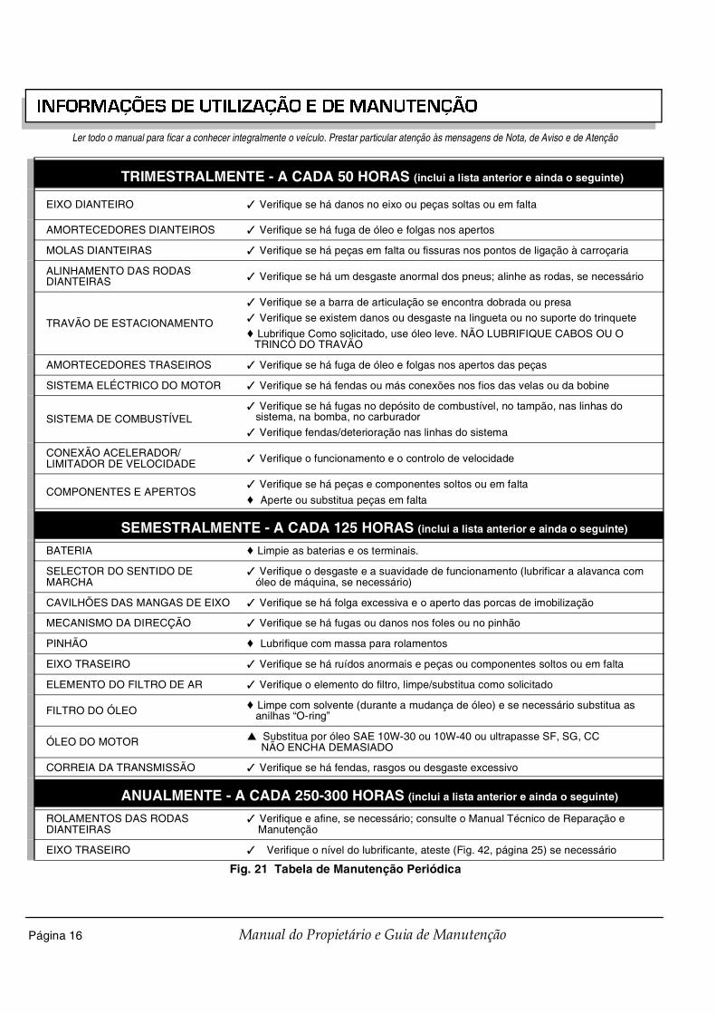
INFORMAÇÕES DE UTILIZAÇÃO E DE MANUTENÇÃO
Página 16 Manual do Propietário e Guia de Manutenção
Ler todo o manual para ficar a conhecer integralmente o veículo. Prestar particular atenção às mensagens de Nota, de Aviso e de Atenção
TRIMESTRALMENTE - A CADA 50 HORAS (inclui a lista anterior e ainda o seguinte)
EIXO DIANTEIRO ✓ Verifique se há danos no eixo ou peças soltas ou em falta
AMORTECEDORES DIANTEIROS ✓ Verifique se há fuga de óleo e folgas nos apertos
MOLAS DIANTEIRAS ✓ Verifique se há peças em falta ou fissuras nos pontos de ligação à carroçaria
ALINHAMENTO DAS RODAS DIANTEIRAS ✓ Verifique se há um desgaste anormal dos pneus; alinhe as rodas, se necessário
TRAVÃO DE ESTACIONAMENTO
✓ Verifique se a barra de articulação se encontra dobrada ou presa
✓ Verifique se existem danos ou desgaste na lingueta ou no suporte do trinquete
♦ Lubrifique Como solicitado, use óleo leve. NÃO LUBRIFIQUE CABOS OU O TRINCO DO TRAVÃO
AMORTECEDORES TRASEIROS ✓ Verifique se há fuga de óleo e folgas nos apertos das peças
SISTEMA ELÉCTRICO DO MOTOR ✓ Verifique se há fendas ou más conexões nos fios das velas ou da bobine
SISTEMA DE COMBUSTÍVEL✓ Verifique se há fugas no depósito de combustível, no tampão, nas linhas do
sistema, na bomba, no carburador
✓ Verifique fendas/deterioração nas linhas do sistema
CONEXÃO ACELERADOR/LIMITADOR DE VELOCIDADE ✓ Verifique o funcionamento e o controlo de velocidade
COMPONENTES E APERTOS✓ Verifique se há peças e componentes soltos ou em falta
♦ Aperte ou substitua peças em falta
SEMESTRALMENTE - A CADA 125 HORAS (inclui a lista anterior e ainda o seguinte)
BATERIA ♦ Limpie as baterias e os terminais.
SELECTOR DO SENTIDO DE MARCHA
✓ Verifique o desgaste e a suavidade de funcionamento (lubrificar a alavanca com óleo de máquina, se necessário)
CAVILHÕES DAS MANGAS DE EIXO ✓ Verifique se há folga excessiva e o aperto das porcas de imobilização
MECANISMO DA DIRECÇÃO ✓ Verifique se há fugas ou danos nos foles ou no pinhão
PINHÃO ♦ Lubrifique com massa para rolamentos
EIXO TRASEIRO ✓ Verifique se há ruídos anormais e peças ou componentes soltos ou em falta
ELEMENTO DO FILTRO DE AR ✓ Verifique o elemento do filtro, limpe/substitua como solicitado
FILTRO DO ÓLEO ♦ Limpe com solvente (durante a mudança de óleo) e se necessário substitua as anilhas “O-ring”
ÓLEO DO MOTOR ▲ Substitua por óleo SAE 10W-30 ou 10W-40 ou ultrapasse SF, SG, CC NÃO ENCHA DEMASIADO
CORREIA DA TRANSMISSÃO ✓ Verifique se há fendas, rasgos ou desgaste excessivo
ANUALMENTE - A CADA 250-300 HORAS (inclui a lista anterior e ainda o seguinte)
ROLAMENTOS DAS RODAS DIANTEIRAS
✓ Verifique e afine, se necessário; consulte o Manual Técnico de Reparação e Manutenção
EIXO TRASEIRO ✓ Verifique o nível do lubrificante, ateste (Fig. 42, página 25) se necessário
Fig. 21 Tabela de Manutenção Periódica

INFORMAÇÕES DE UTILIZAÇÃO E DE MANUTENÇÃO
Página 17Manual do Propietário e Guia de Manutenção
Ler todo o manual para ficar a conhecer integralmente o veículo. Prestar particular atenção às mensagens de Nota, de Aviso e de Atenção
VERIFICAÇÃO DOS PNEUSO estado dos pneus deve ser verificado no intervaloreferido na Tabela de Manutenção Periódica (Fig. 21,página 15). A pressão de enchimento deve ser verificadaquandos os pneus estão frios. Recoloque a tampa daválvula após verificação ou enchimento.
VERIFICAÇÃO DO NÍVEL DO ÓLEONão encha demasiado o motor. Óleo emexcesso pode provocar o fumegar do motor ou
o gripar da vela de ignição.
Ao acrescentar oleo entre mudanças de óleo,não misture óleos de marcas e graus de
viscosidades diferentes. Tanto o tampão do oleo como a varetadeverão ser recolocados no seu lugar antes de utilizar o motor.Qualquer falha nesse ponto resultará numa contaminação dooleo e/ou o mesmo ser espalhado pelo compartimento domotor.
O óleo deverá ser mudado com o motor quente. O veículodeverá estar numa superfície nivelada e com o travão deestacionamento accionado. Deverá deixar o óleo correrpara o cárter antes de o verificar.
Retire a vareta de nível e limpe por completo a áreaindicada com um pano sem algodão descaroçado (Fig. 22,página 17).
Volte a colocar completamente a vareta no reservatório eretire-a. Verifique o nível do óleo na vareta.
O motor poderá funcionar em perfeitas condições desdeque o nível do óleo na vareta mostre que está na alturacorrecta. Não circule com o veículo se o nível do óleo navareta não for o indicado (Fig. 23, página 17).
O óleo deve ser acrescentado para trazer o nível para umlimite seguro de funcionamento. Não ultrapassar. Verifiquese a tampa de enchimento de óleo e a vareta de nível estãofirmes no local.
TRAVÕES DE SERVIÇO
♦ Limpe e afine; consulte o Manual Técnico de Reparação e Manutenção
✓ Verifique as maxilas do travão; consulte o Manual Técnico de Reparação e Manutenção
✓ Verifique níveis do óleo, acrecente se necessário e verifique se há fugas (DOT 3)
FILTRO DO COMBUSTÍVEL ▲ Substitua
VELAS ▲ Substituta, abra novos bujões (Capacidade e peçãs de substitução, página 25)
TUBO E PANELA DE ESCAPE ✓ Verifique o equipamento instalado; verifique se há fugas na cabeça e na panela
VÁLVULAS ✓ Consulte o Manual de Reparações Técnicas
A CADA 500 HORAS (inclui a lista anterior e ainda o seguinte)
CORREIA DE DISTRIBUIÇÃO ✓ Verifique a existência de tensão e sinais de desgaste/danos, substitua se desgastada ou danificada
CARBURADOR ♦ Limpe
CABEÇA DO CILINDRO E PISTÕES♦ Retire o carbono da cabeça do cilindros e dos pistões
✓ Verifique e limpe as bases das válvulas de resíduos de carbono
Fig. 21 Tabela de Manutenção Periódica
AVISO
NOTA
Fig. 22 Limpar toda a vareta de nível
Fig. 23 Verificar o nível do óleo na vareta de nível
F
Ref Ced 1
Nível máximo do óleoNÃO ULTRAPASSAR
Limite segurode funcionamento
Acresc. Cheio
Ref Dsk 1

INFORMAÇÕES DE UTILIZAÇÃO E DE MANUTENÇÃO
Página 18 Manual do Propietário e Guia de Manutenção
Ler todo o manual para ficar a conhecer integralmente o veículo. Prestar particular atenção às mensagens de Nota, de Aviso e de Atenção
MUDANÇA DE ÓLEOFerramentas necessárias Qtd. Necessária
Chave de porcas, 10 mm, cubo de 3/8”........................... 1Roquete, cubo de 3/8" ..................................................... 1Extensão, 8’’, cubo de 3/8’’............................................. 1Panela de recolha............................................................ 1
Para desempenho e longevidade máximos, o óleo do motordeve ser substituído a cada 125 horas de funcionamento ousemestralmente, o que vier primeiro.
A escolha do óleo depende da manutenção desempenhadano veículo. A maioria dos veículos necessita de óleo de10W-30, ao passo que veículos utilizados nas aplicaçõesde capacidade de carga ou perto delas irão necessitar deóleo de 10W-40, depois da rodagem (Fig. 24, página 18).
Para reduzir a possibili-dade de ferimentos gravesou m orte , use luvas de
borracha para proteger a exposição da pele ao calor, aoóleo usado e ao desengordurante. Estes fluidos contémquímicos que reconhecidamente causam cancro.
O óleo deverá ser mudado com o motor quente. Estacioneo veículo numa superfície nivelada, accione o travão deestacionamento e retire a chave. Coloque uma panela derecolha de óleo debaixo do motor. Wipe the top of theengine clean with a cloth (Fig. 25, página 18). Retire atampa de enchimento de óleo.
Limpe bem a área junto ao filtro do óleo. A drenagem doóleo fica completa removendo os três parafusos queprendem o filtro do óleo ao motor. Retire o filtro puxando-odo motor e deixe o óleo drenar. As anilhas “O-Rings” podemficar no motor ou no filtro (Fig. 26, página 18).
Em cada mudança de óleo, inspeccione cuidadosamente ofiltro antes de o limpar. Na primeira mudança de óleopodem ser encontradas limalha metálica e algodãodescaroçado. Isto é normal, resultando da rodagem domotor. Em mudanças de óleo posteriores, a presença delimalhas metálicas pode indicar a possibilidade de danos domotor.
Utilize protecção para os olhos para reduzir apossibilidade de solvente derramado emcontacto com os olhos quando estiver alimpar o filtro do óleo.
Limpe o filtro lavando-o com um desengordurante eescovando o visor de metal, limpar com uma escova suave(Fig. 27, página 18).
Fig. 24 Tabela de viscosidade do óleo
! !� ATENÇÃO
-20 0 20 40 60 80 100
-30 -20 -10 0 10 20 30 40C
F 0
0
10W-3010W-30
10W-4010W-40
TRABALHO PESADO
TRABALHO LEVE
(TEMPERATURA DO AR)
10W-3010W-30
Ref Ovc 1
Fig. 25 Limpe a parte superior do motor
Fig. 26 Retire o filtro do óleo
Fig. 27 Limpar o filtro do óleo
Tampa no bujão
Ref Cte 1
Filtrodo óleo
Anel circular pequeno dentrodo fim do filtro do óleo
Anel circulargrande
Ref Rof 1
Ref Cof 1

INFORMAÇÕES DE UTILIZAÇÃO E DE MANUTENÇÃO
Página 19Manual do Propietário e Guia de Manutenção
Ler todo o manual para ficar a conhecer integralmente o veículo. Prestar particular atenção às mensagens de Nota, de Aviso e de Atenção
Descarregue o filtro com ar de baixa pressão a 210 kPa oumenos a não menos de 8 cm e deixe secar ao ar (Fig. 28,página 19).
Limpe toda a área em redor do filtro com um pano limpo eque não largue pêlos e verifique as anilhas “O-ring”, se fornecessário substitua-as. Coloque o filtro no motor. O filtrodeverá deslizar facilmente para dentro do bocal e encaixar-se-á com uma ligeira pressão. O filtro deverá deslizarfacilmente para dentro do bocal e encaixar-se-á com umaligeira pressão. Instale e aperte com as mãos os parafusosantes de os aparafusar firmemente. Instale e aperte com asmãos os parafusos antes de os aparafusar firmemente.
Acrescente cuidadosamente menos de 1,4 litros para deixarficar algum resto de óleo no motor (Fig. 29, página 19). Oóleo deverá ser de boa qualidade, do tipo API SF, SG ouCC (Fig. 42, página 25). Verifique o nível do óleo na vareta.Se necessário, continue a acrescentar óleo devagar edeixe-o correr para dentro do motor. Verifique o nível doóleo na vareta. Não ultrapassar.
Não encha demasiado o motor. Demasiado óleopoderá causar fumos ou a entrada de óleo no
protector do filtro de ar.
Tanto o tampão do oleo como a vareta deverãoser recolocados no seu lugar antes de utilizar o
motor. Qualquer falha na instalação da vareta de nível e tampade enchimento resultará em derrame de óleo nocompartimento do motor.
Inspeccione o anel circular da tampa de enchimento esubstitua se necessário. Coloque a tampa no bujão. Ponhao veículo a trabalhar durante 1 ou 2 minutos e verifique sehá fugas de óleo no filtro.
Verifique o nível de óleo novamente com o veículo ao níveldo chão. O óleo deve ser acrescentado para trazer o nívelpara um limite seguro de funcionamento. Não ultrapassar.O motor poderá funcionar em perfeitas condições desdeque o nível do óleo na vareta mostre que está na alturacorrecta. Não circule com o veículo se o nível do óleo navareta não for o indicado.
TENSÃO DA CORREIA DO MOTOR DE ARRANQUE/ALTERNADORFerramentas necessárias Qtd. Necessária
Medidor de tensão de correias ........................................ 1Chave de caixa de 3/4" .................................................... 1Chave de caixa de 9/16" .................................................. 2Roquete, cubo de 3/8" ..................................................... 1Chave de caixa, 3/4", cubo de 3/8" .................................. 1
A tensão da correia do arrancador/gerador deve serverificada depois das primeiras 15-20 horas e definida para34 - 36 kg.
Uma correia solta provoca vibração audível e umruído de “chiado”.
Tensionar a correia do motor de arranque/alternador nova(Fig. 42, página 25) para 41 a 50 kg, com o medidor detensão aplicado a meio vão da correia (Fig. 30, página 19).
Uma correia nova pode ser verificada manualmente. Umadeflecção da correia de 10 mm constitui um valor aceitável(Fig. 31, página 20).
Fig. 28 Descarregar o filtro do óleo
Mínimo8 cm
Máximo 210 kPaRef Bof 1
AVISO
NOTA
Fig. 29 Acrescentar óleo do motor
Fig. 30 Verifique a tensão da correia com o indicador
O-ring
Ref Aeo 1
NOTA
Ref Cbg 1
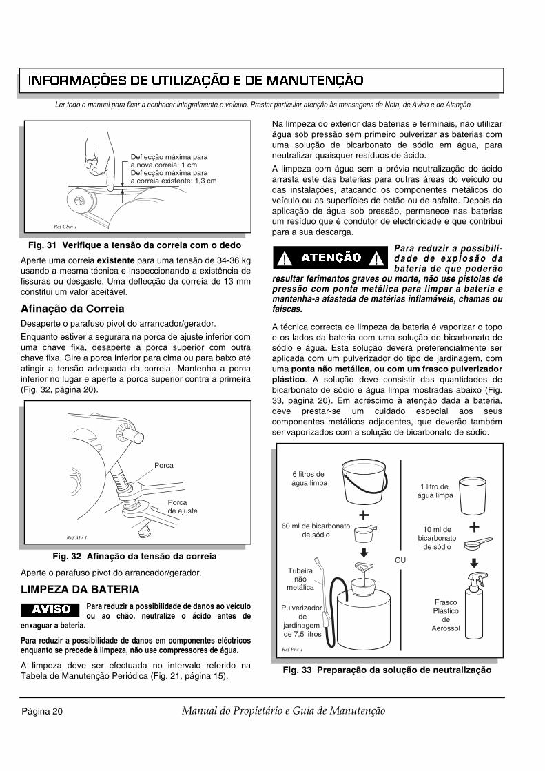
INFORMAÇÕES DE UTILIZAÇÃO E DE MANUTENÇÃO
Página 20 Manual do Propietário e Guia de Manutenção
Ler todo o manual para ficar a conhecer integralmente o veículo. Prestar particular atenção às mensagens de Nota, de Aviso e de Atenção
Aperte uma correia existente para uma tensão de 34-36 kgusando a mesma técnica e inspeccionando a existência defissuras ou desgaste. Uma deflecção da correia de 13 mmconstitui um valor aceitável.
Afinação da CorreiaDesaperte o parafuso pivot do arrancador/gerador.
Enquanto estiver a segurara na porca de ajuste inferior comuma chave fixa, desaperte a porca superior com outrachave fixa. Gire a porca inferior para cima ou para baixo atéatingir a tensão adequada da correia. Mantenha a porcainferior no lugar e aperte a porca superior contra a primeira(Fig. 32, página 20).
Aperte o parafuso pivot do arrancador/gerador.
LIMPEZA DA BATERIAPara reduzir a possibilidade de danos ao veículoou ao chão, neutralize o ácido antes de
enxaguar a bateria.
Para reduzir a possibilidade de danos em componentes eléctricosenquanto se precede à limpeza, não use compressores de água.
A limpeza deve ser efectuada no intervalo referido naTabela de Manutenção Periódica (Fig. 21, página 15).
Na limpeza do exterior das baterias e terminais, não utilizarágua sob pressão sem primeiro pulverizar as baterias comuma solução de bicarbonato de sódio em água, paraneutralizar quaisquer resíduos de ácido.
A limpeza com água sem a prévia neutralização do ácidoarrasta este das baterias para outras áreas do veículo oudas instalações, atacando os componentes metálicos doveículo ou as superfícies de betão ou de asfalto. Depois daaplicação de água sob pressão, permanece nas bateriasum resíduo que é condutor de electricidade e que contribuipara a sua descarga.
Para reduzir a possibili-d a d e d e e x p l o s ã o d abateria de que poderão
resultar ferimentos graves ou morte, não use pistolas depressão com ponta metálica para limpar a bateria emantenha-a afastada de matérias inflamáveis, chamas oufaíscas.
A técnica correcta de limpeza da bateria é vaporizar o topoe os lados da bateria com uma solução de bicarbonato desódio e água. Esta solução deverá preferencialmente seraplicada com um pulverizador do tipo de jardinagem, comuma ponta não metálica, ou com um frasco pulverizadorplástico. A solução deve consistir das quantidades debicarbonato de sódio e água limpa mostradas abaixo (Fig.33, página 20). Em acréscimo à atenção dada à bateria,deve prestar-se um cuidado especial aos seuscomponentes metálicos adjacentes, que deverão tambémser vaporizados com a solução de bicarbonato de sódio.
Fig. 31 Verifique a tensão da correia com o dedo
Fig. 32 Afinação da tensão da correia
Deflecção máxima paraa nova correia: 1 cm Deflecção máxima paraa correia existente: 1,3 cm
Ref Cbm 1
Porca
Porcade ajuste
Ref Abt 1
AVISO
Fig. 33 Preparação da solução de neutralização
! !� ATENÇÃO
6 litros de água limpa
60 ml de bicarbonatode sódio
Pulverizador de
jardinagem de 7,5 litros
Ref Pns 1
1 litro de água limpa
10 ml debicarbonato
de sódio
FrascoPlástico
deAerossol
OUTubeira
nãometálica

INFORMAÇÕES DE UTILIZAÇÃO E DE MANUTENÇÃO
Página 21Manual do Propietário e Guia de Manutenção
Ler todo o manual para ficar a conhecer integralmente o veículo. Prestar particular atenção às mensagens de Nota, de Aviso e de Atenção
Deixar a solução actuar, pelo menos, 3 minutos; com umaescova macia ou um pano limpo, limpar os topos dasbaterias, para remover os resíduos que possam provocar aauto-descarga da bateria. Enxaguar com água limpaaplicada com baixa pressão. Não usar compressores deágua.
TRAVÕES
Para reduzir a possibi li-dade de ferimentos gravesou morte, avalie sempre o
funcionamento do pedal antes de utilizar um veículo, paraverificar se há função de travagem.
Todos os testes de travagem deverão ser executados numlocal que garanta a segurança de todas as pessoas quepossam estar nas proximidades.
Com o passar do tempo, pode ocorrer uma ligeiraperda de eficácia; por isso, é importante
conhecer qual o comportamento normal do veículo em novo.
O Teste Periódico de Travagem deverá ser executadoregularmente (Fig. 21, página 15) como avaliação dodesempenho do sistema de travagem. É um método útilpara identificar ligeiras perdas de eficácia que ocorrem como tempo.
Teste periódico de travagem para travões mecânicosO objectivo deste teste é comparar o desempenho detravagem do veículo com o de veículos novos ou ‘em boascondições’, ou estabelecer uma distância aceitável detravagem. As distâncias reais de travagem sãoinfluenciadas por condições atmosféricas, pelo estado dopiso, pelo peso do veículo (acessórios incluídos) e pela suavelocidade. Não pode ser determinada com segurançanenhuma distância exacta de travagem. O teste éefectuado accionando o travão de mão para eliminarpressões no pedal diferentes e para incluir os efeitos defalhas nas conexões.
Determine a distância aceitável de distância testando umveículo novo ou ‘em boas condições’ e registando o local deimobilização ou a distância de travagem. Para frotas deveículos, deverão ser testados vários veículos enquantonovos e registadas as suas distâncias de travagem oulocais de imobilização.
Com o passar do tempo, pode ocorrer uma ligeiraperda de eficácia; por isso, é importante
conhecer qual o comportamento normal do veículo em novo.
Conduza o veículo num piso plano, seco, limpo e asfaltadoà sua velocidade máxima (Fig. 34, página 21). Na linha oumarcador da área de teste, pressione rapidamente o pedaldo travão para accionar o travão de estacionamento e retireo pé do pedal. O veículo deverá para bruscamente. Asrodas poderão bloquear ou não. Observe o local deimobilização do veículo ou meça a distância de travagem apartir do ponto em que os travões foram accionados. Oveículo deverá para dentro do limite ‘normal’ das distânciasde imobilização. Se o veículo parar a mais de 1,2 m paraalém da distância aceitável de travagem, ou se a direcção‘puxar’ para um dos lados, reprova e deverá passar pornovo processo de teste.
Se o veículo falhar o segundo teste, deverá serimediatamente retirado de serviço. O veículo deverá serinspeccionado por um mecânico qualificado que deveconsultar a secção DIAGNÓSTICO DE ANOMALIAS noManual Técnico de Reparação e Manutenção.
Fig. 34 Teste típico de desempenho de travagem
Liberte otravão deestacionamento eretire o pé do pedal
Linha ou marcador
Distânciaaceitávelde travagem Valores médios para a
distância de travagemQualquer veículo quepare a mais de 1,2 mpara além da distânciaaceitável de travagemou cuja direcção “puxe”para um dos lados deveráser retirado de serviço edeixado aos cuidados deum mecânico qualificado
Acelere até àvelocidade máxima
1,2 mLinha ou marcador
Superfície seca, nivelada, limpa e asfaltada
Ref Bpt 1
! !� ATENÇÃO
NOTA
NOTA

INFORMAÇÕES DE UTILIZAÇÃO E DE MANUTENÇÃO
Página 22 Manual do Propietário e Guia de Manutenção
Ler todo o manual para ficar a conhecer integralmente o veículo. Prestar particular atenção às mensagens de Nota, de Aviso e de Atenção
Travões de Disco Frontais HidráulicosPara veículos equipados com travões de disco frontaishidráulicos, verifique o fluido do cilindro principal de acordocom O PROGRAMA DE MANUTENÇÃO PERIÓDICA ou seexistir um decréscimo na eficácia da travagem. Inspeccionedanos ou desgaste dos componentes. É pouco provávelque o fluido necessite de ser acrescentado, a não ser queexista uma fuga no sistema. Levante a frente do veículo(Consultar elevação do veículo). Retire a roda/pneu do ladodo passageiro. Com cuidado, limpe a sujidade e resíduosdo cilindro principal e tape, antes de abrir. Retire a tampa.Utilizando um espelho de mecânico, verifique se o fluidonão está a mais de ¼” abaixo do topo do reservatório.Adicione fluido DOT 3 ou 4 como solicitado.
ENTRADA DE AR E VENTOINHA
P a r a e v i t a r p o s s í v e i squeimaduras, as peças dom o t o r d e v e r ã o s e r
mantidas limpas para reduzir o risco de sobre-aquecimetoe de ignição de detritos acumulados.
Após qualquer utilização em estrada, permita que o motorarrefeça e verifique se se formou uma cobertura desujidade de detritos nas entradas de ar e na ventoinha. Asujidade e os detritos podem obstruir o sistema dearrefecimento. Limpe as áreas exibidas para evitar danosno motor (Fig. 35, página 22) (Fig. 36, página 22).Mantenha as ligações, as molas e os comandos limpos.Mantenha a área em redor da panela de escape limpa dequalquer material combustível.
EIXO TRASEIROO eixo traseiro é fornecido com um verificador do nível delubrificante localizado do lado do condutor, na traseira doeixo (Fig. 37, página 22). É suficiente uma revisão anual, anão ser que haja alguma fuga de lubrificante no eixotraseiro.
Verificação do Nível do LubrificanteFerramentas necessárias Qtd. Necessária
Chave de porcas, 13 mm, cubo de 3/8”........................... 1Roquete, cubo de 3/8" ..................................................... 1Funil ................................................................................. 1
Limpe a área à volta do depósito o bujão de enchimento.Retire o bujão de verificação. O nível correcto delubrificante situa-se imediatamente abaixo do furo roscadodo bujão (Fig. 42, página 25). Se tiver que acrescentarlubrificante, retire o bujão de enchimento e acrescente olubrificante com a ajuda de um funil. Acrescente lentamenteo lubrificante até que o mesmo comece a sair pelo furoroscado do bujão. Instale o bujão de verificação e o bujãode enchimento. Caso seja necessário proceder à mudançado lubrificante, a bainha do diferencial dispõe de um bujãode drenagem.
Fig. 35 Limpar a entrada de ar
! !� ATENÇÃO
Ref Cai 1
Fig. 36 Limpar o radiador de aletas
Fig. 37 Acrescentar, verificar e drenar o lubrificante do eixo posterior
Ref Ccf 1
Bujão de verificação
Bujão de drenagemRef Raf 2
Bujão deenchimento

INFORMAÇÕES DE UTILIZAÇÃO E DE MANUTENÇÃO
Página 23Manual do Propietário e Guia de Manutenção
Ler todo o manual para ficar a conhecer integralmente o veículo. Prestar particular atenção às mensagens de Nota, de Aviso e de Atenção
INSPECÇÃO E SUBSTITUIÇÃODO FILTRO DO AR
Para reduzir a danos no motor, certifique-se deque os separadores da base da tampa estão
instalados no compartimento e o topo da tampa está instalado sobos separadores superiores. Prensa todos os grampos das molas.
O sistema de limpeza de ar do veículo, é umsistema seco. Nunca ponha óleo no filtro ou em
qualquer outra parte do sistema. Para ajudar na instalação evedação, pode ser aplicada vaselina ao lado posterior dosseparadores da tampa e em cada lado do vedante do filtro.
O sistema de limpeza do ar está ligado ao motor e pode seracedido levantado o assento. Inspeccione e substitua ofiltro do ar de acordo com o Programa de ManutençãoPeriódica (Fig. 21, página 15). Pode aceder ao sistema delimpeza de ar retirando os encaixes da caixa de ar eabrindo a tampa. Retire a tampa e o elemento do filtro de ar(Fig. 38, página 23). Instale o novo elemento do mesmo modoque o filtro antigo foi removido, certificando-se que ovedante do filtro está instalado correctamente. Insira atampa na parte mais baixa do compartimento e gire-a paracima para o lugar. Encaixe e coloque as cavilhas.Certifique-se de que a tampa se adequa sob osseparadores e que todos os grampos estão apertados deforma segura.
Limpeza do Elemento do Filtro de ArNão use ar comprimido para limpar o filtro do ar;se o fizer, irá danificar o filtro, o que pode
resultar em dano para o motor.
Limpe a parte de dentro da tampa e o interior. Nunca ponhaóleo no filtro ou em qualquer outra parte do sistema.
Caixa Tipo do Sistema de Limpeza do ArO elemento do sistema de limpeza de ar fica acessíveldesenroscando os grampos na caixa-de-ar e removendo atampa e o elemento do filtro de ar (Fig. 39, página 23).Limpe o interior da tampa, caixa e colector de pó. Instale oelemento e tape da mesma forma que foram removidos.Certifique-se de que o posicionamento da seta na tampaestá apontado para cima e de que todos os grampos estãopresos de forma segura.
Limpeza do Elemento do Filtro de ArNão use ar comprimido para limpar o filtro do ar;se o fizer, irá danificar o filtro, o que pode
resultar em dano para o motor.
Limpe a parte de dentro da tampa e o interior. Nunca ponhaóleo no filtro ou em qualquer outra parte do sistema. Instaleo elemento na mesma maneira que se removeu, sendocerto que os grampos estão prendidos firmemente.
LUBRIFICAÇÃONão use mais de três (3) bombadas de massalubrificante de cada vez em cada copo de
lubrificação. O excesso de massa lubrificante pode provocar roturados vedantes de massa ou a entrada de massa lubrificante emzonas que possam danificar componentes.
Colocar mais de três bombadas do produto lubrificante emcada copo de lubrificação poderá prejudicar oscomponentes do motor e provocar falhas prematuras nossuportes (Fig. 40, página 23).
Fig. 38 Filtro do ar
AVISO
NOTA
Ref Air 1
Os lados frontal e posteriordo vedante dos separadores
podem ser lubrificadoscom vaselina
Os lados frontal e posteriordo vedante do filtro de arpodem ser lubrificados
com vaselina
AVISO
Fig. 39 Caixa tipo do sistema de limpeza do ar
Fig. 40 Pontos de lubrificação
Colectorde Pó
Coberturado filtro do ar
Caixa do sistemade limpeza do ar
Elemento dofiltro de ar
Ref Air 2
AVISO
AVISO
Vista da parte de baixo do veículo
Rótula daCremalheira
Ref Lub 1

INFORMAÇÕES DE UTILIZAÇÃO E DE MANUTENÇÃO
Página 24 Manual do Propietário e Guia de Manutenção
Ler todo o manual para ficar a conhecer integralmente o veículo. Prestar particular atenção às mensagens de Nota, de Aviso e de Atenção
VELASFerramentas necessárias Qtd. Necessária
Chave de velas, 13/16", cubo de 1/2".............................. 1Roquete, cubo de 1/2" ..................................................... 1Apalpa folgas tipo arame ................................................. 1Isolante ......................................................................... ARChave dinamométrica, cubo de 1/2", ft. lbs. .................... 1
Não apertar excessivamente as velas. O apertoexcessivo pode provocar a danificação das
roscas da cabeça do motor (alumínio).
Retire e inspeccione as velas de ignição nos intervalosindicados no Programa de Manutenção Periódica (Fig. 21,página 15). Todas as velas de ignição novas devem seradequadamente abertas antes da instalação (Fig. 42,página 25). Aplique uma leve camada de isolante e apertecom uma força de 24 Nm.
As velas sujas apresentam depósitos húmidos e negros.Estes depósitos podem ser provocados por sujidade noelemento do filtro de ar ou a outras restrições à livrecirculação do ar no sistema de admissão. As velas comfolgas incorrectas ou com eléctrodos em mau estado, assimcomo a utilização de combustíveis sujos ou de qualidadeinferior podem também contribuir para o problema.
ARMAZENAMENTO PROLONGADOPara reduzir a possibili-dade de ferimentos gravesou morte resultantes de
uma possível explosão:Não manuseie combustível em áreas não ventiladas.Não fume perto do depósito de combustível ouabasteça perto de chamas ou de aparelhos passíveisde produzir faíscas.Armazene o veículo numa área limpa e seca. Nãoa rm a ze n e na m e s m a ár e a f o g õ es , c a ld e i ra saquecedores de água ou outros aparelhos que tenhauma luz piloto ou capacidade de produzir faíscas.Ao reabastecer, verifique se o tampão do depósito temfugas ou fendas que possam originar derramamentode combustível.Use sempre óculos de protecção ao reabastecer paraevitar possíveis danos na vista provocados pelagasolina ou pelos seus vapores.Manter as mãos, roupa e joalharia afastados de peçasem movimento. Evite tocar em objectos quentes.Eleve a traseira do veículo e sustente-a em apoios deelevação antes de iniciar ou afinar a cadeia dinâmica.
A preparação de armazenamento do veículo por umperíodo de tempo prolongado (30 dias ou mais) exige aexecução de algumas operações muito simples, com vista aimpedir a formação de lacas ou gomas no carburador e acorrosão do motor.
• Eleve a traseira do veículo e apoie-a em calços deapoio à elevação. Consulte o capítulo ‘Elevação doveículo’ acerca do procedimento correcto deelevação e informações de segurança.
• Desligue o tubo de combustível do depósito decombustível e tape-o convenientemente.
• Com a ventilação adequada, carregue no pedal doacelerador e permita que o motor trabalhe ate pararpor falta de combustível.
• Retire as velas de ignição (VELAS, página 24) eescoe cerca de 30 ml do oleo do motor para dentrode cada cilindro. Substitua as velas, as suasligações e use o motor de arranque para colocar omotor a trabalhar um pouco, para que o óleo seespalhe.
• Junte um aditivo de gasolina ao depósito de acordocom as recomendações do fabricante.
• Torne a ligar o tubo de combustível ao depósito ecircule com o veículo para que o aditivo chegue aocarburador.
• Enquanto o motor ainda estiver quente, mude o óleo(MUDANÇA DE ÓLEO, página 18).
• Limpe a carroçaria, chassis e motor dos detritos,lama, debulho ou erva (ENTRADA DE AR EVENTOINHA, página 22).
COMPONENTESVerificar periodicamente se existem parafusos soltos noveículo. Os parafusos deverão ser apertados com osmomentos de aperto indicados na tabela (Fig. 41, página25).
Apertar os parafusos com cuidado e consultar no ManualTécnico de Reparação e Manutenção os momentos deaperto recomendados.
Geralmente, há três níveis de equipamento para estesveículos. O equipamento de grau 5 identifica-se por trêsmarcas na cabeça hexagonal, e o de grau 8 é identificadopor 6 marcas na cabeça. Um veículo sem marcas nacabeça é de grau 2 (Fig. 41, página 25).
AVISO
! !� ATENÇÃO

INFORMAÇÕES DE UTILIZAÇÃO E DE MANUTENÇÃO
Página 25Manual do Propietário e Guia de Manutenção
Ler todo o manual para ficar a conhecer integralmente o veículo. Prestar particular atenção às mensagens de Nota, de Aviso e de Atenção
CAPACIDADE E PEÇAS DE SUBSTITUIÇÃO
Fig. 41 Momentos de Aperto
MOMENTOS DE APERTO EM FT. LBS. (Nm)
PARAFUSO
Grau 2
1/4" 5/16" 3/8" 7/16" 1/2" 9/16" 5/8" 3/4" 7/8" 1"
Salvo indicação em contrário no texto, a parafusaria deverá ser apertada com os momentos indicados nesta tabela. A tabelaabaixo indica os momentos de aperto recomendados para roscas lubrificadas. Os parafusos cadmiados ou lubrificados na altura da
instalação são considerados “oleados” e devem ser apertados com 80% dos momentos indicados para os parafusos com rosca ”seca”.
4(5)
8(11)
15(20)
24(33)
35(47)
55(75)
75(102)
130(176)
125(169)
190(258)
Grau 5
Grau 8
6(8)
13(18)
23(31)
35(47)
55(75)
80(108)
110(149)
200(271)
320(434)
480(651)
6(8)
18(24)
35(47)
55(75)
80(108)
110(149)
170(230)
280(380)
460(624)
680(922)
PARAFUSO
Classe 5.8(Grau 2)
M4 M5 M6 M8 M10 M12 M14
1(2)
2(3)
4(6)
10(14)
20(27)
35(47)
55(76.4)
Classe 8.8(Grau 5)
2(3)
4(6)
7(10)
18(24)
35(47)
61(83)
97(131)
Classe 10.9(Grau 8)
3(4)
6(8)
10(14)
25(34)
49(66)
86(117)
136(184)
5.8
8.8
10.9
Ref Tsp 1
Fig. 42 Capacidade e peçãs de substitução
Depósito Comb./Comb.
Óleo do Motor
Filtro do Óleo
Filtro do Ar
Velas de Ignição
Correia do Arrancador/
Gerador
Correia da Embraiagem
Óleo do Eixo Posterior
Fusível
Lâmpada de Iluminação
Lâmpada Marcadora
Lâmpada Sinal Viragem
Lâmpada Iluminação Taipal
22,5 / 87 Octanas
1,4 l
1,2 l
15 A (N/P 35212-G01)
N/P 20209-G3
#912 (N/P 74005-G01)
#1157 (N/P 21759-G1)
N/P 26591-G01
N/P 72368-G01 Filtro do Painel
N/P 28463-G01 Filtro da Caixa
NGK BPR4ES (N/P 25523-G3) 295 cc
NGK BPR5ES (N/P 25523-G4) 350 cc
Fissura de 0,71 - 0,76 mm
N/P 26414-G01
N/P 72054-G01
#1157 (N/P 21759-G1)
Ref Cap 10

INFORMAÇÕES DE UTILIZAÇÃO E DE MANUTENÇÃO
Página 26 Manual do Propietário e Guia de Manutenção
Ler todo o manual para ficar a conhecer integralmente o veículo. Prestar particular atenção às mensagens de Nota, de Aviso e de Atenção

Página 27
ESPECIFICAÇÕES GERAIS
Manual do Propietário e Guia de Manutenção
ESPECIFICAÇÕES GERAIS

Página 28 Manual do Propietário e Guia de Manutenção
ESPECIFICAÇÕES GERAIS
MPT™ 800EQUIPAMENTO NORMAL:PESO (tanque vazio 355 kg capacidade de combustível 16 kgPNEUS (PARA OS 4) 18 x 8,50 x 8 (para os 4)PRESSÃO DOS PNEUS 124 -152 kPaCAPACIDADE DE CARGA 362 kg (incluindo o operador, passageiro, carga e acessórios)DISTÂNCIA DO CHÃO 12,7 cm no diferencialESTRUTURA Aço tubular forte fornecido com alta soldadura com pintura de camada de póCARROÇARIA E ACABAMENTOS Frente: Painéis flexíveis, resistentes a impacto. Acabamento com camada de cor/limpar
camada Traseiras: Painéis leves substituíveis de aço.
SEGURANÇA O interruptor de chave instalado no painel de instrumentos, o indicador de aviso de marcha-atrás, controlo de acelerador "barra de ancoragem", tensor manual integral em restrições da bacia, selector manual de marcha para a frente / para trás com ponto-morto, buzina eléctrica, placa do patim do diferencial, protector do motor
LUZES Iluminação de halogéneo dupla, iluminação traseira opcional, luzes de travagem, piscasVOLANTE Tensores manuais duplosTRAVÕES Rodas traseiras mecânicas, com ajuste dos travões. Combinação de travão de serviço/
estacionamento com libertação automática do travão de estacionamento (acelerador de arranque) Travões de discos frontais hidráulicos adicionais
SUSPENSÃO DIANTEIRA Molas de folha de serviço pesadas com absorventes de choque hidráulicosSUSPENSÃO TRASEIRA Molas de folha de serviço pesadas com absorventes de choque hidráulicosSISTEMA DE DIRECÇÃO Direcção simples auto-compensada com redução de cremalheira e carretosPAINEL DE INSTRUMENTOS Resistente à abrasão com quatro suportes de bebidas, saída de 12 V, indicador de
combustível, luz indicadora de pressão de oleo baixaBANCOS As tampas de vinil forradas a tecido moldado sobre a espuma da almofada de assento.
Assento para operador e um passageiroMOTOR Cilindro duplo refrigerado a ar calculado para 6,7 kW, 4 ciclos 295 ccVÁLVULAS Válvulas dianteiras, excêntricos dianteiros, correia de direcçãoLUBRIFICAÇÃO Sistema de lubrificação pressurizado, filtro permanente lavávelESTABILIZADOR Eixo de equilíbrio de conta rotações internoIGNIÇÃO Estado Sólido, temporização electrónica avançada e limitador de RPMCARBURADOR Bomba de combustível de jacto fixo, de impulso remotoSISTEMA DE LIMPEZA DE AR Elemento de cartucho seco substituívelSISTEMA DE TRANSMISSÃO Transmissão automática, continuamente variável (TCV)SISTEMA ELÉCTRICO Arrancador/Gerador externo, regulador de Estado Sólido, bateria livre de manutenção de 12 V,
425 CCA, 60 minutos de reservaTRANSMISSÃO Diferencial de alta eficácia com engrenagens helicoidais, relação de 13,32:1, controlador da
velocidade em relação à terra, marcha para a frente e trás com bloqueio de ponto morto.DEPÓSITO DE COMBUSTÍVEL 23 lVELOCIDADE 21 km/h ± 0,8 km/h
Especificações sujeitas a alteração sem aviso prévio

Página 29
ESPECIFICAÇÕES GERAIS
Manual do Propietário e Guia de Manutenção
MPT™ 1200EQUIPAMENTO NORMAL:PESO (tanque vazio 390 kg capacidade de combustível 16 kgPNEUS (PARA OS 4) 18 x 8,50 x 8 (para os 4)PRESSÃO DOS PNEUS 124 -152 kPaCAPACIDADE DE CARGA 544 kg (incluindo o operador, passageiro, carga e acessórios)DISTÂNCIA DO CHÃO 12,7 cm no diferencialESTRUTURA Aço tubular forte fornecido com alta soldadura com pintura de camada de póCARROÇARIA E ACABAMENTOS Frente: Painéis flexíveis, resistentes a impacto. Acabamento com camada de cor/limpar
camada Traseiras: Painéis leves substituíveis de aço.
SEGURANÇA O interruptor de chave instalado no painel de instrumentos, o indicador de aviso de marcha-atrás, controlo de acelerador "barra de ancoragem", tensor manual integral em restrições da bacia, selector manual de marcha para a frente / para trás com ponto-morto, buzina eléctrica, placa do patim do diferencial, protector do motor
LUZES Iluminação de halogéneo dupla, iluminação traseira opcional, luzes de travagem, piscasVOLANTE Tensores manuais duplosTRAVÕES Rodas traseiras mecânicas, com ajuste dos travões. Combinação de travão de serviço/
estacionamento com libertação automática do travão de estacionamento (acelerador de arranque) Travões de discos frontais hidráulicos adicionais
SUSPENSÃO DIANTEIRA Molas de folha de serviço pesadas com absorventes de choque hidráulicosSUSPENSÃO TRASEIRA Molas de folha de serviço pesadas com absorventes de choque hidráulicosSISTEMA DE DIRECÇÃO Direcção simples auto-compensada com redução de cremalheira e carretosPAINEL DE INSTRUMENTOS Resistente à abrasão com quatro suportes de bebidas, indicador de combustível, luz
indicadora de pressão de óleo baixaBANCOS As tampas de vinil forradas a tecido moldado sobre a espuma da almofada de assento.
Assento para operador e um passageiroMOTOR Cilindro duplo refrigerado a ar calculado para 8,2 kW, 4 ciclos 350 ccVÁLVULAS Válvulas dianteiras, excêntricos dianteiros, correia de direcçãoLUBRIFICAÇÃO Sistema de lubrificação pressurizado, filtro permanente lavávelESTABILIZADOR Eixo de equilíbrio de conta rotações internoIGNIÇÃO Estado Sólido, temporização electrónica avançada e limitador de RPMCARBURADOR Bomba de combustível de jacto fixo, de impulso remotoSISTEMA DE LIMPEZA DE AR Elemento de cartucho seco substituívelSISTEMA DE TRANSMISSÃO Transmissão automática, continuamente variável (TCV)SISTEMA ELÉCTRICO Arrancador/Gerador externo, regulador de Estado Sólido, bateria livre de manutenção de
12 V, 425 CCA, 60 minutos de reservaTRANSMISSÃO Diferencial de alta eficácia com engrenagens helicoidais, relação de 13,32:1, controlador da
velocidade em relação à terra, marcha para a frente e trás com bloqueio de ponto morto.DEPÓSITO DE COMBUSTÍVEL 23 lVELOCIDADE 21 km/h ± 0,8 km/h
Especificações sujeitas a alteração sem aviso prévio
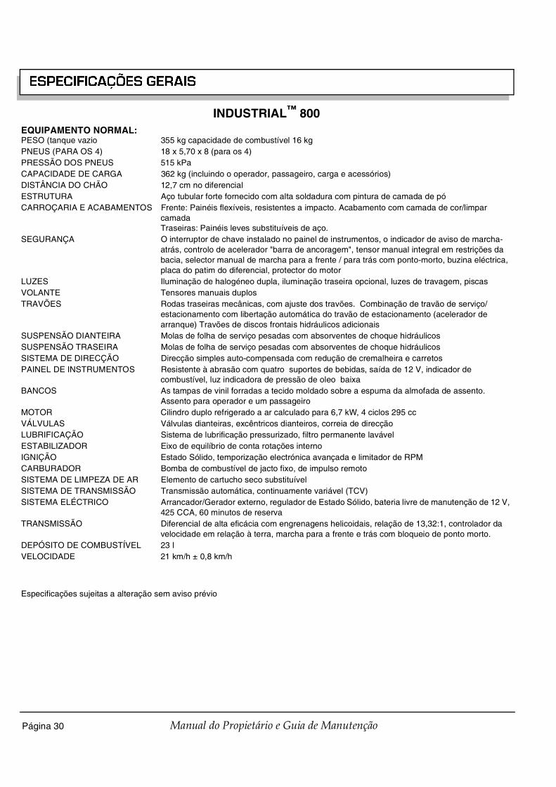
Página 30 Manual do Propietário e Guia de Manutenção
ESPECIFICAÇÕES GERAIS
INDUSTRIAL™ 800EQUIPAMENTO NORMAL:PESO (tanque vazio 355 kg capacidade de combustível 16 kgPNEUS (PARA OS 4) 18 x 5,70 x 8 (para os 4)PRESSÃO DOS PNEUS 515 kPaCAPACIDADE DE CARGA 362 kg (incluindo o operador, passageiro, carga e acessórios)DISTÂNCIA DO CHÃO 12,7 cm no diferencialESTRUTURA Aço tubular forte fornecido com alta soldadura com pintura de camada de póCARROÇARIA E ACABAMENTOS Frente: Painéis flexíveis, resistentes a impacto. Acabamento com camada de cor/limpar
camada Traseiras: Painéis leves substituíveis de aço.
SEGURANÇA O interruptor de chave instalado no painel de instrumentos, o indicador de aviso de marcha-atrás, controlo de acelerador "barra de ancoragem", tensor manual integral em restrições da bacia, selector manual de marcha para a frente / para trás com ponto-morto, buzina eléctrica, placa do patim do diferencial, protector do motor
LUZES Iluminação de halogéneo dupla, iluminação traseira opcional, luzes de travagem, piscasVOLANTE Tensores manuais duplosTRAVÕES Rodas traseiras mecânicas, com ajuste dos travões. Combinação de travão de serviço/
estacionamento com libertação automática do travão de estacionamento (acelerador de arranque) Travões de discos frontais hidráulicos adicionais
SUSPENSÃO DIANTEIRA Molas de folha de serviço pesadas com absorventes de choque hidráulicosSUSPENSÃO TRASEIRA Molas de folha de serviço pesadas com absorventes de choque hidráulicosSISTEMA DE DIRECÇÃO Direcção simples auto-compensada com redução de cremalheira e carretosPAINEL DE INSTRUMENTOS Resistente à abrasão com quatro suportes de bebidas, saída de 12 V, indicador de
combustível, luz indicadora de pressão de oleo baixaBANCOS As tampas de vinil forradas a tecido moldado sobre a espuma da almofada de assento.
Assento para operador e um passageiroMOTOR Cilindro duplo refrigerado a ar calculado para 6,7 kW, 4 ciclos 295 ccVÁLVULAS Válvulas dianteiras, excêntricos dianteiros, correia de direcçãoLUBRIFICAÇÃO Sistema de lubrificação pressurizado, filtro permanente lavávelESTABILIZADOR Eixo de equilíbrio de conta rotações internoIGNIÇÃO Estado Sólido, temporização electrónica avançada e limitador de RPMCARBURADOR Bomba de combustível de jacto fixo, de impulso remotoSISTEMA DE LIMPEZA DE AR Elemento de cartucho seco substituívelSISTEMA DE TRANSMISSÃO Transmissão automática, continuamente variável (TCV)SISTEMA ELÉCTRICO Arrancador/Gerador externo, regulador de Estado Sólido, bateria livre de manutenção de 12 V,
425 CCA, 60 minutos de reservaTRANSMISSÃO Diferencial de alta eficácia com engrenagens helicoidais, relação de 13,32:1, controlador da
velocidade em relação à terra, marcha para a frente e trás com bloqueio de ponto morto.DEPÓSITO DE COMBUSTÍVEL 23 lVELOCIDADE 21 km/h ± 0,8 km/h
Especificações sujeitas a alteração sem aviso prévio

Página 31
ESPECIFICAÇÕES GERAIS
Manual do Propietário e Guia de Manutenção
INDUSTRIAL™ 1200EQUIPAMENTO NORMAL:PESO (tanque vazio 390 kg capacidade de combustível 16 kgPNEUS (PARA OS 4) 18 x 5,70 x 8 (para os 4)PRESSÃO DOS PNEUS 515 kPaCAPACIDADE DE CARGA 544 kg (incluindo o operador, passageiro, carga e acessórios)DISTÂNCIA DO CHÃO 12,7 cm no diferencialESTRUTURA Aço tubular forte fornecido com alta soldadura com pintura de camada de póCARROÇARIA E ACABAMENTOS Frente: Painéis flexíveis, resistentes a impacto. Acabamento com camada de cor/limpar
camada Traseiras: Painéis leves substituíveis de aço.
SEGURANÇA O interruptor de chave instalado no painel de instrumentos, o indicador de aviso de marcha-atrás, controlo de acelerador "barra de ancoragem", tensor manual integral em restrições da bacia, selector manual de marcha para a frente / para trás com ponto-morto, buzina eléctrica, placa do patim do diferencial, protector do motor
LUZES Iluminação de halogéneo dupla, iluminação traseira opcional, luzes de travagem, piscasVOLANTE Tensores manuais duplosTRAVÕES Rodas traseiras mecânicas, com ajuste dos travões. Combinação de travão de serviço/
estacionamento com libertação automática do travão de estacionamento (acelerador de arranque) Travões de discos frontais hidráulicos adicionais
SUSPENSÃO DIANTEIRA Molas de folha de serviço pesadas com absorventes de choque hidráulicosSUSPENSÃO TRASEIRA Molas de folha de serviço pesadas com absorventes de choque hidráulicosSISTEMA DE DIRECÇÃO Direcção simples auto-compensada com redução de cremalheira e carretosPAINEL DE INSTRUMENTOS Resistente à abrasão com quatro suportes de bebidas, indicador de combustível, luz
indicadora de pressão de óleo baixaBANCOS As tampas de vinil forradas a tecido moldado sobre a espuma da almofada de assento.
Assento para operador e um passageiroMOTOR Cilindro duplo refrigerado a ar calculado para 8,2 kW, 4 ciclos 350 ccVÁLVULAS Válvulas dianteiras, excêntricos dianteiros, correia de direcçãoLUBRIFICAÇÃO Sistema de lubrificação pressurizado, filtro permanente lavávelESTABILIZADOR Eixo de equilíbrio de conta rotações internoIGNIÇÃO Estado Sólido, temporização electrónica avançada e limitador de RPMCARBURADOR Bomba de combustível de jacto fixo, de impulso remotoSISTEMA DE LIMPEZA DE AR Elemento de cartucho seco substituívelSISTEMA DE TRANSMISSÃO Transmissão automática, continuamente variável (TCV)SISTEMA ELÉCTRICO Arrancador/Gerador externo, regulador de Estado Sólido, bateria livre de manutenção de
12 V, 425 CCA, 60 minutos de reservaTRANSMISSÃO Diferencial de alta eficácia com engrenagens helicoidais, relação de 13,32:1, controlador da
velocidade em relação à terra, marcha para a frente e trás com bloqueio de ponto morto.DEPÓSITO DE COMBUSTÍVEL 23 lVELOCIDADE 21 km/h ± 0,8 km/h
Especificações sujeitas a alteração sem aviso prévio

Página 32 Manual do Propietário e Guia de Manutenção
ESPECIFICAÇÕES GERAIS
Fig. 43 Dimensões do veículo
MPT™ 800INDUSTRIAL™ 800
MPT™ 1200INDUSTRIAL™ 1200
262 cm
Traseira97 cm
Dianteira97 cm
89 cm
25 cm119 cm
119 cm
168 cm
282 cm
29 cm
46 cm
108 cm
127 cm
Traseira97 cm
Dianteira97 cm
119 cm
196 cm
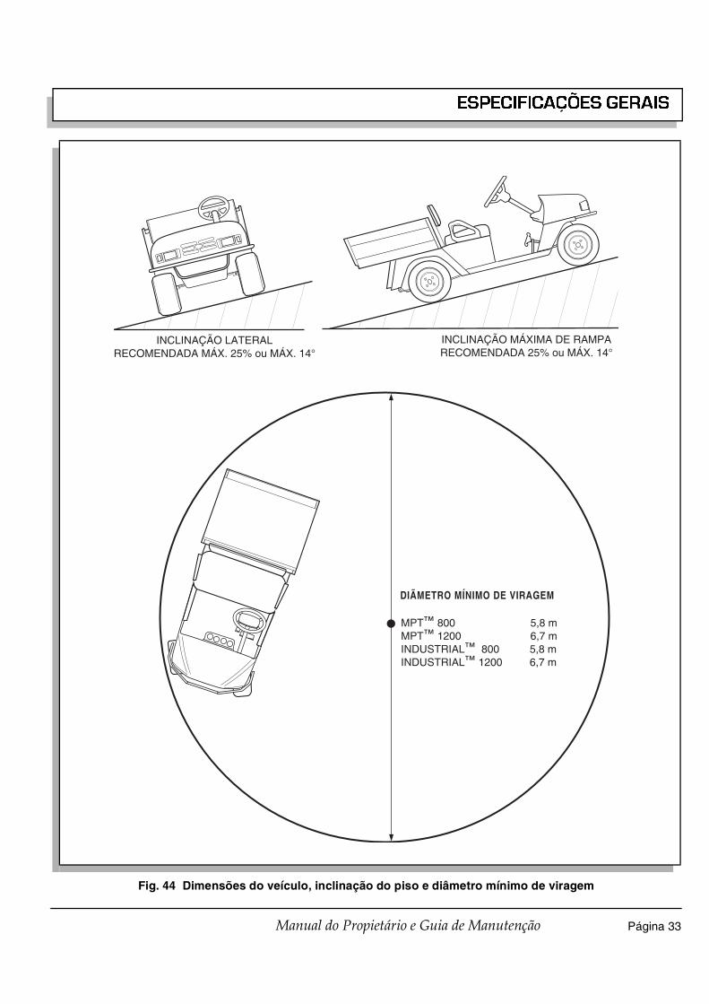
Página 33
ESPECIFICAÇÕES GERAIS
Manual do Propietário e Guia de Manutenção
Fig. 44 Dimensões do veículo, inclinação do piso e diâmetro mínimo de viragem
INCLINAÇÃO MÁXIMA DE RAMPARECOMENDADA 25% ou MÁX. 14°
INCLINAÇÃO LATERALRECOMENDADA MÁX. 25% ou MÁX. 14°
DIÃMETRO MÍNIMO DE VIRAGEM
MPT™ 800 5,8 mMPT™ 1200 6,7 mINDUSTRIAL™ 800 5,8 mINDUSTRIAL™ 1200 6,7 m

Página 34 Manual do Propietário e Guia de Manutenção
ESPECIFICAÇÕES GERAIS
Notas:

Página 35Manual do Propietário e Guia de Manutenção
GARANTIAS DO VEÍCULO
GARANTIAS DO VEÍCULO

Página 36 Manual do Propietário e Guia de Manutenção
GARANTIAS DO VEÍCULO
GARANTIA DOMÉSTICA(EUA E CANADÁ)
Para obter uma cópia da garantia limitada aplicável ao veículo, telefone ou escreva a um distribuidor local, a um Concessionário autorizado ou ao Departamento de Garantias, referindo o número de série do veículo e o código da data de fabrico.

Página 37
GARANTIAS DO VEÍCULO
Manual do Propietário e Guia de Manutenção
GARANTIA INTERNACIONAL 2004(TODOS OS PAÍSES EXCEPTO OS EUA E CANADÁ)
E-Z-GO DIVISION OF TEXTRON INC. (“E-Z-GO”) garante ao Primeiro Proprietário ou ao Primeiro Locatário que qualquer que veículo ou carregador Modelo E-Z-GO do ano de 2004 se encontram isentos de defeitos de material ou de fabrico durante um ano a partir da data de entrega ao cliente no que toca a peças e a utilização.
EXCLUSÕES: Excluem-se especificamente de qualquer garantia da E-Z-GO as afinações ou reparações originadas por desgaste de utilização normal durante os primeiros 180 dias, peças que requeiram manutenção de rotina, deterioração cosmética e componentes eléctricos sujeitos a sobrecargas ou corrente instável fora do controlo da E-Z-GO. Esta garantia também não se aplica a fenómenos naturais ou outras ocorrências sobre as quais a E-Z-GO não tem qualquer controlo. Dentro do prazo de validade da garantia, as despesas decorrentes do transporte do veículo para reparação e as do envio de peças não estão incluídas nesta garantia e as peças substituídas tornam-se propriedade da E-Z-GO. Esta garantia também exclui baterias, pneumáticos, e carregadores de baterias Lester, que são garantidos pelos seus respectivos fabricantes.
SOLUÇÃO: A única solução ao abrigo desta garantia, e a única obrigação da E-Z-GO na eventualidade de surgir algum defeito no veículo/carregador da bateria, é a E-Z-GO proceder, à sua inteira discrição, à reparação ou substituição de quaisquer peças defeituosas. Esta solução exclui todas as outras, incluindo processos judiciais, reclamações, ou outros procedimentos que aleguem responsabilidade objectiva, negligência contratual, ou qualquer outra pretensão. A E-Z-GO reserva-se o direito de melhorar ou alterar a concepção de qualquer veículo ou carregador de bateria E-Z-GO sem assumir qualquer responsabilidade pela modificação de quaisquer veículos ou carregadores de bateria fabricados anteriormente.
RENÚNCIA: ESTA GARANTIA É VÁLIDA EM VEZ DE QUAISQUER OUTRAS GARANTIAS IMPLÍCITAS OU EXPRESSAS, INCLUINDO QUALQUER GARANTIA DE COMERCIALIZAÇÃO OU ADEQUAÇÃO PARA FIM ESPECÍFICO. A E-Z-GO RENUNCIA AINDA QUALQUER RESPONSABILIDADE POR DANOS INDIRECTOS OU LUCROS CESSANTES, INCLUINDO SEM SE LIMITAR, LESÕES CORPORAIS OU DANOS MATERIAIS DECORRENTES DE QUALQUER DEFEITO NO VEÍCULO OU CARREGADOR DA BATERIA.
Nenhum agente, funcionário ou representante da E-Z-GO, ou qualquer outra pessoa, tem autoridade para obrigar a E-Z-GO a qualquer outro acordo, declaração ou garantia relativamente aos produtos vendidos ao abrigo desta garantia.
ATENÇÃO: QUALQUER MODIFICAÇÃO OU ALTERAÇÃO DO VEÍCULO, QUE ALTERE A DISTRIBUIÇÃO DO PESO DO VEÍCULO, A SUA ESTABILIDADE OU AUMENTE A SUA VELOCIDADE PARA ALÉM DAS CARACTERÍSTICAS TÉCNICAS DE FÁBRICA, PODE PROVOCAR LESÕES CORPORAIS GRAVES. NUNCA EFECTUAR TAIS MODIFICAÇÕES OU ALTERAÇÕES. A E-Z-GO PROÍBE E DECLINA QUALQUER RESPONSABILIDADE POR QUAISQUER MODIFICAÇÕES OU QUAISQUER OUTRAS ALTERAÇÕES AS QUAIS POSSAM AFECTAR ADVERSAMENTE A SEGURANÇA DO VEÍCULO.
ANULAÇÃO DA GARANTIA: ESTA E QUALQUER OUTRA GARANTIA SERÃO ANULADAS SE O VEÍCULO O CARREGADOR DA BATERIA: FOR DANIFICADO OU NÃO UTILIZADO PARA A FINALIDADE A QUE SE DESTINA; ESTIVER ENVOLVIDO EM ACIDENTE OU COLISÃO; APRESENTAR INDÍCIOS DE QUE O REGULADOR DA VELOCIDADE FOI ALTERADO OU MODIFICADO, DE MODO A QUE A OPERAÇÃO DO VEÍCULO EXCEDA AS ESPECIFICAÇÕES DA E-Z-GO; APRESENTE INDÍCIOS DE QUE AS ESPECIFICAÇÕES DA E-Z-GO FORAM ALTERADAS OU MODIFICADAS DE QUALQUER FORMA, INCLUINDO, SEM SE LIMITAR, A ALTERAÇÕES À VELOCIDADE, SISTEMA DE TRAVAGEM, DIRECÇÃO OU OUTROS SISTEMAS DE OPERAÇÃO DO VEÍCULO; OU APRESENTAR INDÍCIOS DE QUE A MANUTENÇÃO DE ROTINA NÃO FOI EFECTUADA NOS INTERVALOS E MODO ESPECIFICADOS NO MANUAL DE MANUTENÇÃO DA E-Z-GO. ESTA GARANTIA SERÁ ANULADA RELATIVAMENTE A QUAISQUER DEFEITOS OU DANOS CAUSADOS POR, OU RESULTANTES DE, OU RELACIONADOS COM PEÇAS OU ACESSÓRIOS NÃO FABRICADOS OU NÃO AUTORIZADOS PELA E-Z-GO, OU QUANDO NÃO INSTALADOS DE ACORDO COM AS INSTRUÇÕES DA E-Z-GO OU, NO CASO DE VEÍCULOS COM MOTOR A GASOLINA, SE FOREM UTILIZADOS COMBUSTÍVEIS E LUBRIFICANTES NÃO RECOMENDADOS.
PARA INFORMAÇÕES ADICIONAIS, TELEFONE PARA O 1-706-798-4311 OU ESCREVA PARA A E-Z-GO DIVISION OF TEXTRON INC. AO CUIDADO DE: DEPARTAMENTO DE GARANTIAS, P.O. BOX 388, AUGUSTA, GEORGIA 30903-0388

Página 38 Manual do Propietário e Guia de Manutenção
GARANTIAS DO VEÍCULO
Notas:

Página 39
GARANTIAS DO VEÍCULO – FEDERAL (2004)
Manual do Propietário e Guia de Manutenção
GARANTIA FEDERAL DE COMPONENTE DE EMISSÃO COM DEFEITO
COBERTURA DA GARANTIA DE COMPOENTE COM DEFEITO DE EMISSÕES – Esta garantia de emissão é aplicável em todos os Estados, excepto no Estado da Califórnia
Fuji Heavy Industries Ltd. e E-Z-GO Division of Textron Augusta, Georgia, (doravente “E-Z-GO”) garante(m) ao comprador de retalho inicial e a cada proprietário, que este motor de não utilização na estrada (doravante "motor") foi concebido, construído e equipado para de acordo com a altura da venda inicial a todas as regulações da Agência de Protecção Ambiental dos Estados Unidos (APA), e que o motor está livre de defeitos materiais e humanos que possam provocar o não funcionamento deste motor de acordo com as regulamentações da APA durante o seu período de garantia.
Para os componentes listados abaixo como PEÇAS ABRANGIDAS, o distribuidor, agente, ou fornecedor de manutenção autorizado pela E-Z-GO fará gratuitamente o diagnóstico necessário, reparação ou substituição necessária para assegurar que o motor cumpre os regulamentos da APA EU.
PERÍODO DE GARANTIA DE COMPONENTE DE EMISSÃO COM DEFEITO
O período de garantia para este veículo começa no dia da venda ao primeiro comprador e tem um período de 2 anos.
COBERTURA DE COMPONENTES
Na lista a seguir discriminada estão todos os componentes cobertos pela Garantia de Defeito em Componente. Alguns componentes desta lista podem exigir um período de manutenção e a garantia diz respeito ao primeiro período de substituição desse componente.
1) Sistema de Medição de Combustível(i) Carburador e todos os componentes interiores (e/ou regulador de pressão ou sistema de injecção de combustível).(ii) Realimentação da relação ar/combustível e sistema de controlo, se aplicável.(iii) Sistema de Arranque a frio, se for aplicável.(iv) Conjunto regulador (combustível gasoso, se aplicável).
2) Sistema de Indução de Ar(i) Tubo de Distribuição de Admissão, se for aplicável.(ii) Filtro do Ar.
3) Sistema de Arranque(i) Velas de Ignição. (ii) Sistema de magneto ou electónico de ignição. (iii) Sistema de velas avançado/retardado, se for aplicável.
4) Colector de escape, se aplicável5) Todos os vários itens utilizados nos seguintes Sistemas
(i) Controlos electrónicos, se for aplicável.(ii) Depósitos, correias, conectores e montagens.(iii) Conjunto de bloqueio do filtro (combustível gasoso, se aplicável).
OBTENÇÃO DE SERVIÇOS DENTRO DO PRAZO DE GARANTIA
Para obter os serviços da garantia, leve o seu motor para o distribuidor, agente ou fornecedor do serviço E-Z-GO mais próximo. Leve também a factura de compra do veículo que indica a data em que foi comprado. O distribuidor, agente, ou fornecedor do serviço autorizado pela E-Z-GO desempenhará as reparações ou ajustes dentro de um período razoável de tempo e fornece-lhe uma cópia da ordem de reparação. Todos os componentes e acessórios substituídos substituídos dentro desta garantia passam a ser propriedade da E-Z-GO.
TUDO O QUE NÃO ESTÁ ABRANGIDO• As condições resultantes de falsificação, má utilização, ajuste inadequado ( a não ser que tenham sido feitos
pelo distribuidor, agente, ou fornecedor do serviço autorizado pela E-Z-GO durante a reparação coberta pela garantia), alteração, acidente, erro de utilização do combustível ou óleo recomendados, ou não desempenho dos serviços de manutenção requeridos.
• A substituição de componentes necessários durante as revisões.• Danos incidentais tais como a perda de tempo, inconveniência, perda de utilização do motor ou equipamento,
etc.• Custos de diagnóstico e inspecção que não resultem no serviço abrangido pela garantia.• Qualquer substituição não autorizada, ou má substituição autorizada de componentes por utilização de
componentes não autorizados.

Página 40 Manual do Propietário e Guia de Manutenção
GARANTIAS DO VEÍCULO – FEDERAL (2004)
RESPONSABILIDADES DE GARANTIA DO PROPRIETÁRIO
Enquanto proprietário do veículo, é reponsável pela realização das revisões descritas no Manual do Utilizador. A E-Z-GO recomenda que guarde todos os recibos que dizem respeito às revisões do seu veículo, mas a E-Z-GO não pode anular a garantia apenas pelo facto de faltarem recibos ou por ter falhado alguma das revisões recomendadas.
Como proprietário do motor, deve, o entanto, estar consciente de que a E-Z-GO pode negar a cobertura da garantia se o seu motor um uma peça tiver falhado devido a abuso, negligência, manutenção inadequada ou modificações desaprovadas.
É responsável por apresentar o seu motor ao distribuidor, agente ou fornecedor do serviço mais próximo autorizado pela E-Z-GO quando existir um problema.
Se tiver alguma dúvida no que diz respeito aos direitos e repsonsabilidades da garantia, deverá contactar o Departamento de Garantias da E-Z-GO através do nº 1-800-241-5855.
TUDO O QUE DEVE SABER SOBRE A EMISSÃO DA GARANTIA
MANUTENÇÃO E REPARAÇÕES
É responsável pela manutenção apropriada do motor. Deve guardar todos os recibos e registos de manutenção que abranjam o desempenho de manutenção regular no caso de serem levantadas questões. Estes recibos e registos de manutenção devem ser transferidos para cada proprietário posterior do motor. E-Z-GO reserva o direito de anular uma garantia se o veículo não estiver em perfeitas condições. Todas as reclamações dentro do período da garantia serão aceites, excepto no caso de as revisões não estarem em ordem ou de faltarem registos de manutenções.
A MANUTENÇÃO, SUBSTITUIÇÃO OU REPARAÇÃO DE DISPOSITICOS DE CONTROLO DE EMISSÃO E SISTEMAS PODE SER DESEMPENHADA POR QUALQUER ESTABELECIMENTO DE REPARAÇÃO OU INDIVÍDUO; NO ENTANTO AS REPARAÇÕES ABRANGIDAS PELA GARANTIA DEVEM SER DESEMPENHADAS POR UM DISTRIBUIDOR, AGENTE OU FORNECEDOR DE SERVIÇO AUTORIZADO PELA E-Z-GO. A SUBSTITUIÇÃO POR PEÇAS QUE NÃO SEJAM EQUIVALENTES EM DESEMPENHO E DURABILIDADE PODERÃO COMPROMETER A EFECTIVIDADE DO SISTEMA CONTROLADOR E PODERÃO PRODUZIR UM INDEFERIMENTO NA RECLAMAÇÃO DA GARANTIA.
Se forem utilizadas peças diferentes das autorizadas pela E-Z-GO nas substituições de manutenção ou para reparação de componentes que afectem o sistema de controlo, deverá confirmar que tais peças estão abrangidas pela garantia do seu fabricante e que são equivalentes às peças autorizadas pela E-Z-GO, no que respeita o seu desempenho e durabilidade.
COMO RECLAMAR
Toda a reparação qualificada sob esta garantia limitada deve ser desempenhada por um distribuidor, agente ou fornecedor de serviço autorizado pela E-Z-GO. No caso de alguma peça relacionada com emissão ser considerada defeituosa durante o período da garantia, deve notificar o Departamento de Garantia da E-Z-GO pelo 1-800-241-5855 e será aconselhado relativamente aos fornecedores do serviço coberto pela garantia adequado onde a reparação pode ser efectuada.
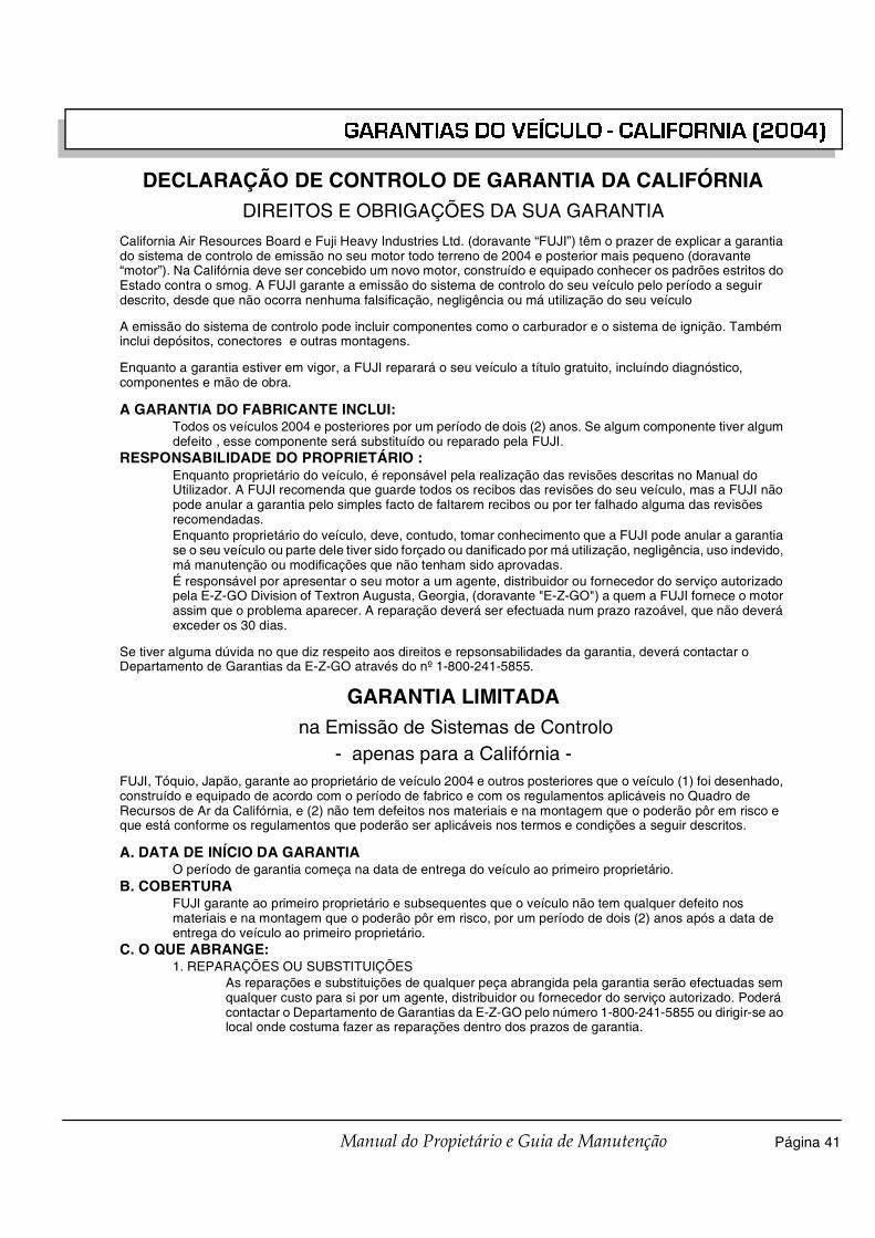
Página 41
GARANTIAS DO VEÍCULO - CALIFORNIA (2004)
Manual do Propietário e Guia de Manutenção
DECLARAÇÃO DE CONTROLO DE GARANTIA DA CALIFÓRNIADIREITOS E OBRIGAÇÕES DA SUA GARANTIA
California Air Resources Board e Fuji Heavy Industries Ltd. (doravante “FUJI”) têm o prazer de explicar a garantia do sistema de controlo de emissão no seu motor todo terreno de 2004 e posterior mais pequeno (doravante “motor”). Na Califórnia deve ser concebido um novo motor, construído e equipado conhecer os padrões estritos do Estado contra o smog. A FUJI garante a emissão do sistema de controlo do seu veículo pelo período a seguir descrito, desde que não ocorra nenhuma falsificação, negligência ou má utilização do seu veículo
A emissão do sistema de controlo pode incluir componentes como o carburador e o sistema de ignição. Também inclui depósitos, conectores e outras montagens.
Enquanto a garantia estiver em vigor, a FUJI reparará o seu veículo a título gratuito, incluíndo diagnóstico, componentes e mão de obra.
A GARANTIA DO FABRICANTE INCLUI:Todos os veículos 2004 e posteriores por um período de dois (2) anos. Se algum componente tiver algum defeito , esse componente será substituído ou reparado pela FUJI.
RESPONSABILIDADE DO PROPRIETÁRIO :Enquanto proprietário do veículo, é reponsável pela realização das revisões descritas no Manual do Utilizador. A FUJI recomenda que guarde todos os recibos das revisões do seu veículo, mas a FUJI não pode anular a garantia pelo simples facto de faltarem recibos ou por ter falhado alguma das revisões recomendadas.Enquanto proprietário do veículo, deve, contudo, tomar conhecimento que a FUJI pode anular a garantia se o seu veículo ou parte dele tiver sido forçado ou danificado por má utilização, negligência, uso indevido, má manutenção ou modificações que não tenham sido aprovadas.É responsável por apresentar o seu motor a um agente, distribuidor ou fornecedor do serviço autorizado pela E-Z-GO Division of Textron Augusta, Georgia, (doravante "E-Z-GO") a quem a FUJI fornece o motor assim que o problema aparecer. A reparação deverá ser efectuada num prazo razoável, que não deverá exceder os 30 dias.
Se tiver alguma dúvida no que diz respeito aos direitos e repsonsabilidades da garantia, deverá contactar o Departamento de Garantias da E-Z-GO através do nº 1-800-241-5855.
GARANTIA LIMITADA na Emissão de Sistemas de Controlo
- apenas para a Califórnia -FUJI, Tóquio, Japão, garante ao proprietário de veículo 2004 e outros posteriores que o veículo (1) foi desenhado, construído e equipado de acordo com o período de fabrico e com os regulamentos aplicáveis no Quadro de Recursos de Ar da Califórnia, e (2) não tem defeitos nos materiais e na montagem que o poderão pôr em risco e que está conforme os regulamentos que poderão ser aplicáveis nos termos e condições a seguir descritos.
A. DATA DE INÍCIO DA GARANTIAO período de garantia começa na data de entrega do veículo ao primeiro proprietário.
B. COBERTURAFUJI garante ao primeiro proprietário e subsequentes que o veículo não tem qualquer defeito nos materiais e na montagem que o poderão pôr em risco, por um período de dois (2) anos após a data de entrega do veículo ao primeiro proprietário.
C. O QUE ABRANGE:1. REPARAÇÕES OU SUBSTITUIÇÕES
As reparações e substituições de qualquer peça abrangida pela garantia serão efectuadas sem qualquer custo para si por um agente, distribuidor ou fornecedor do serviço autorizado. Poderá contactar o Departamento de Garantias da E-Z-GO pelo número 1-800-241-5855 ou dirigir-se ao local onde costuma fazer as reparações dentro dos prazos de garantia.

Página 42 Manual do Propietário e Guia de Manutenção
GARANTIAS DO VEÍCULO - CALIFORNIA (2004)
2. PERÍODO DA GARANTIAEsta garantia continua por um período de dois (2) anos e deverá ser aplicada em reparações, substituições ou ajustes de componentes que não o sejam nas revisões. Além disso, os componentes que tenham uma revisão recomendada no capítulo “reparação ou substituição se necessário” estão abrangidas pela garantia. Qualquer componente que tenha a sua substituição recomendada deverá ser feita dentro do período da garantia.
3. DIAGNÓSTICONão deve ser cobrado por nenhum trabalho de diagnóstico que conduza à determinação de que uma peça abrangida pela garantia está defeituosa, se o trabalho de diagnóstico for desempenhado num agente autorizado, distribuidor ou fornecedor do serviço.
4. CONSEQUENTES DANOSSe a peça abrangida pela garantia falhar provocando danos a outros componentes do motor, consulte um fornecedor do serviço.
D. TUDO O QUE NÃO ESTÁ ABRANGIDO1. Esta garantia limitada não cobre qualquer componente que tenha sido mal manuseado, ou que esteja
danificado devido ao não cumprimento das seguintes instruções de manutenção e operação descritas no Manual do Utilizador do veículo 2004, incluído:
(1) Inspecção e manutenção programadas do motor inadequadas.(2) Manutenção inadequada de quaisquer peças abrangidas pela garantia.(3) Instalação, ajuste ou reparação inadequada do motor ou de qualquer peça abrangida pela
garantia excepto se desempenhada por um agente autorizado.(4) O não cumprimento das recomendações de utilização do combustível expostas no Manual
do Utilizador.(5) Reparações efectudas fora dos serviços autorizados.(6) Utilização de componentes que não sejam autorizados pela FUJI.
2. Componentes acrescentados ou modificadosEsta garantia não abrange qualquer componente com defeito, falhas ou danificado devido a alterações no veículo.
3. Despesas ocorridas pelo processo de reclamaçãoFUJI, qualquer agente, distribuidores e fornecedores do serviço autorizados não devem ser responsabilizados por qualquer perda de utilização do motor, qualquer utilização alternativa, danos de bens, perda de tempo ou inconveniência.
E. COMO FAZER A RECLAMAÇÃOTodas as reparações qualificadas sob esta Garantia Limitada devem ser desempenhadas por um agente que lhe tenha vendido o motor ou distribuidores, ou fornecedores de serviço autorizado pela E-Z-GO. No caso de encontrar qualquer componente com defeito durante o período de garantia, deverá notificar o Departamento de Garantias da E-Z-GO pelo número 1-800-241-5855 onde lhe serão dadas todas as indicações.
F. ONDE OBTER OS SERVIÇOSÉ recomendado que o serviço de garantia seja desempenhado por um agente autorizado que lhe tenha vendido o motor, embora o serviço de garantia venha a ser desempenhado por quaisquer agentes autorizados, distribuidores e fornecedores do serviço em qualquer parte dos Estados Unidos. Quando é necessária uma reparação abrangida pela garantia, o motor deve ser trazido até à sede de um agente autorizado, fornecedor de serviço ou distribuição durante as horas de expediente. Em todos os casos, a reparação deverá ser fectuada dentro de um perído de tempo razoável, que não deverá exceder os 30 dias.
G. MANUTENÇÕES, SUBSTITUIÇÕES E REPARAÇÕES DE COMPONENTESApenas podem ser utilizados componentes de veículos aprovados pela FUJI para substituições ou manutenções. Se forem utilizados outros na reparação, manutenção ou substituição de componentes que poderão afectar o veículo, deverá confirmar que esses componentes estão abrangidos pela garantia do seu próprio fabricante no que diz respeito à durabilidade e desempenho. Contudo, a FUJI, refere que não poderá ser responsabilizada pela utilização de outros componentes que não sejam autorizados. A utilização de componentes de substituição não autorizados não invalida a garantia no que diz respeito a outros componentes a não ser no que refere aos componentes não autorizados que poderão danificar os componentes abrangidos por esta garantia.

Página 43
GARANTIAS DO VEÍCULO - CALIFORNIA (2004)
Manual do Propietário e Guia de Manutenção
H. COMPONENTES ABRANGIDOS PELAS GARANTIAS EMITIDAS NA CALIFÓRNIA(1) Sistema de Medição de Combustível
(i) Carburador e todos os componentes interiores (e/ou regulador de pressão ou sistema de injecção de combustível).(ii) Realimentação da relação ar/combustível e sistema de controlo, se aplicável.(iii) Sistema de Arranque a frio, se for aplicável.(iv) Conjunto regulador (combustível gasoso, se aplicável).
(2) Sistema de Indução de Ar(i) Tubo de Distribuição de Admissão, se for aplicável.(ii) Filtro do Ar.
(3) Sistema de Arranque(i) Velas de Ignição.(ii) Sistema de magneto ou electónico de ignição. (iii) Sistema de velas avançado/retardado, se for aplicável.
(4) Colector de escape, se aplicável(5) Todos os vários itens utilizados nos seguintes Sistemas
(i) Controlos electrónicos, se for aplicável.(ii) Mangueiras, correias, conectores e conjuntos.(iii) Conjunto de bloqueio do filtro (combustível gasoso, se aplicável).
I. RELATÓRIOS DE MANUTENÇÕESÉ da sua responsabilidade a realização de todas as inspecções e manutenções recomendadas no Manual do Utilizador, e a manutenção de todos os registos que provem que as inspecções e manutenções foram efectuadas nos prazos recomendados. A FUJI não anulará uma reclamação de garantia pelo simples facto de faltarem registos de algumas manutenções; contudo pode declinar uma reclamação de garantia por ter falhado alguma das revisões recomendadas, e, por esse motivo, qualquer componente se danificar. Os registos das suas manutenções deverão ser entregues ao subsequente proprietário do veículo. É responsável pela realização das manutenções recomendadas descritas na Tabela de Manutenções Periódicas do Manual do Utilizador. As revisões periódicas baseiam-se no normal funcionamento do seu veículo.

Página 44 Manual do Propietário e Guia de Manutenção
GARANTIAS DO VEÍCULO - CALIFORNIA (2004)

Página 45Manual do Propietário e Guia de Manutenção
DECLARAÇÃO DE CONFORMIDADE
DECLARAÇÃO DE CONFORMIDADE(EUROPA APENAS)

Página 46 Manual do Propietário e Guia de Manutenção
DECLARAÇÃO DE CONFORMIDADE
DECLARAÇÃO DE CONFORMIDADE
NÃO DISPONÍVEL
AQUANDO
DA PUBLICAÇÃO

Página 47Manual do Propietário e Guia de Manutenção
DECLARAÇÃO DE CONFORMIDADE
DECLARAÇÃO DE CONFORMIDADE(EUROPA APENAS)

Página 48 Manual do Propietário e Guia de Manutenção
DECLARAÇÃO DE CONFORMIDADE
Página 49
DECLARAÇÃO DE CONFORMIDADE
Manual do Propietário e Guia de Manutenção

Página 50 Manual do Propietário e Guia de Manutenção
DECLARAÇÃO DE CONFORMIDADE
Notas:

Apêndice A - 1
ETIQUETAS E PICTOGRAMAS
Manual do Propietário e Guia de Manutenção
ETIQUETAS E PICTOGRAMAS

Apêndice A - 2 Manual do Propietário e Guia de Manutenção
ETIQUETAS E PICTOGRAMAS
35962G0135964G01
!
!
RF
< 14° 25%
P
F
!
< 14° 25%35962-G01
74443G01Leia nas páginasseguintes aexplicação destespictogramas: (1,2)
Leia nas páginasseguintes a
explicação destespictogramas:(19,43,44,45)
OFFON
71131-G01
71131G01
Leia nas páginasseguintes a
explicação destespictogramas:
(2,3,4,6,9,36,37,38,39,40,29)
71489G01
Leia nas páginasseguintes a
explicação destespictogramas:
(1,2)
35493G01 71771G01
Leia nas páginas seguintes aexplicação destes
pictogramas: (28)
28203G01Leia nas páginas seguintes a
explicação destespictogramas:(20,1,21,22)
Pb35493-G01
2820
3-G
01
Numa bateria por baixo do assento
ATENÇÃO
Os pára-brisas nãooferecem protecçãocontra bolas degolfe ou outrosobjectos voadores.
EGWHL14
Leia nas páginas seguintes aexplicação destes pictogramas: (30)
ATENÇÃO
Mantenha todo ocorpo dentro doveículo.
27653G01
Leia nas páginas seguintes aexplicação destes pictogramas: (49)
NÃO ADULTERE OU MODIFIQUE ESTE AJUSTE DO REGULADOR DEVELOCIDADE. IGNORAR ESTE AVISO PODERÁ DAR ORIGEM AFERIMENTOS PESSOAIS GRAVES E ANULARÁ A GARANTIA DO VEÍCULO.
ATENÇÃO
24880G01
Esta etiqueta está situadana tampa do controladorno topo do eixo posterior
H O2
1 2 3
PP
PP PP74093-G01
74093G01
71419G01 (24)71417G01 (25)71415G01 (26)
Leia nas páginasseguintes a
explicação destespictogramas:(23,27,18,20,
22,17,15)
PP
MAX250 lbs.114 kg
MAX 4 in.10 cm
MAX14o / 25%
!35980G01
35980G0135980G02 35980G03 35980G04
Leia nas páginasseguintes aexplicação destespictogramas: (1,2,12,10,8,7,5,11)
74821G0174821G02 74821G03
Leia nas páginasseguintes aexplicação destespictogramas: (1,2,12,10,8,11,51,7,5)
!
1. Para evitar deslizamentos para trás num terreno inclinado a partir de uma Posiçcão Parada
3. Liberte totalmente o travão
2. Accione o travão de serviço com o péeé esquerdo
4. Pressione o acelerador enquanto liberta o travão de serviço à medida que o veículo inicia a marcha
74443G01
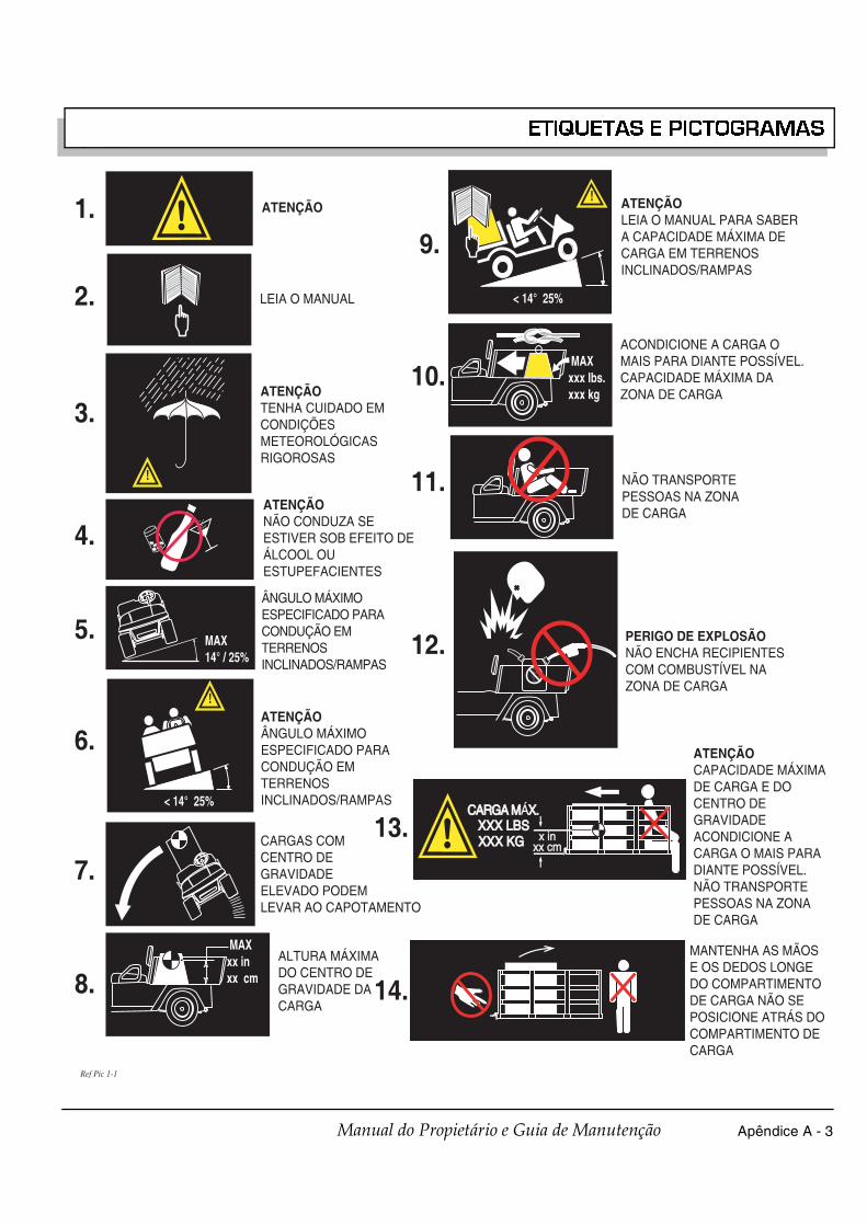
Apêndice A - 3Manual do Propietário e Guia de Manutenção
ETIQUETAS E PICTOGRAMAS
ATENÇÃO
LEIA O MANUAL
!
ATENÇÃOTENHA CUIDADO EMCONDIÇÕESMETEOROLÓGICASRIGOROSAS
ATENÇÃONÃO CONDUZA SEESTIVER SOB EFEITO DEÁLCOOL OUESTUPEFACIENTES
MAX14° / 25%
ÂNGULO MÁXIMOESPECIFICADO PARACONDUÇÃO EMTERRENOSINCLINADOS/RAMPAS
!
< 14° 25%
ATENÇÃOÂNGULO MÁXIMOESPECIFICADO PARACONDUÇÃO EMTERRENOSINCLINADOS/RAMPAS
CARGAS COMCENTRO DEGRAVIDADEELEVADO PODEMLEVAR AO CAPOTAMENTO
MAXxx inxx cm
ALTURA MÁXIMADO CENTRO DEGRAVIDADE DACARGA
!
< 14° 25%
ATENÇÃOLEIA O MANUAL PARA SABERA CAPACIDADE MÁXIMA DECARGA EM TERRENOSINCLINADOS/RAMPAS
MAXxxx lbs.xxx kg
ACONDICIONE A CARGA OMAIS PARA DIANTE POSSÍVEL.CAPACIDADE MÁXIMA DAZONA DE CARGA
NÃO TRANSPORTEPESSOAS NA ZONADE CARGA
PP
PERIGO DE EXPLOSÃONÃO ENCHA RECIPIENTESCOM COMBUSTÍVEL NAZONA DE CARGA
x inx inxx cmxx cm
CARGA MCARGA MÁX.X.XXX LBSXXX LBSXXX KGXXX KG
ATENÇÃOCAPACIDADE MÁXIMADE CARGA E DOCENTRO DEGRAVIDADEACONDICIONE ACARGA O MAIS PARADIANTE POSSÍVEL.NÃO TRANSPORTEPESSOAS NA ZONADE CARGA
MANTENHA AS MÃOSE OS DEDOS LONGEDO COMPARTIMENTODE CARGA NÃO SEPOSICIONE ATRÁS DOCOMPARTIMENTO DECARGA
1.9.
10.
11.
12.
13.
14.
2.
3.
4.
5.
6.
7.
8.
Ref Pic 1-1

Apêndice A - 4 Manual do Propietário e Guia de Manutenção
ETIQUETAS E PICTOGRAMAS
1 3H O2PP
LIMPAR OSDERRAMES DECOMBUSTÍVEL COMÁGUA ANTES DECOLOCAR O MOTOREM FUNCIONAMENTOPP
GASOLINA SEMCHUMBO
PPBOMBA COMLIGAÇÃO À TERRA
PP
NÃO DERRAMECOMBUSTÍVEL SOBREUM MOTOR QUENTE
NÃO MEXERMANTENHA ASMÃOS AFASTADAS
BORNE NEGATIVODA BATERIA LIGADOÀ TERRA
NÃO LIGUE O BORNEPOSITIVO DA BATERIAÀ TERRA
O CONTACTO ENTRE OS BORNESDA BATERIA PODE CAUSAR UMA EXPLOSÃO
NÃO EXPORA CHAMAS
ATENÇÃOCORROSIVO
ATENÇÃOVOLTAGEM LETAL
ATENÇÃOPERIGO DE EXPLOSÃO
NÃO LANCE ASBATERIAS À TERRA
NÃO CONDUZAEM AUTO-ESTRADA
PRESSÃO DO ÓLEO BAIXAOS PÁRA-BRISASNÃO OFERECEMPROTECÇÃO CONTRAOBJECTOS VOADORES
AS BATERIAS SÃOPESADAS.CUIDADO AOLEVANTAR
USE FERRAMENTASISOLADAS
USE PROTECÇÃOOCULAR
NÃO FUMAR
SUPERFÍCIE QUENTE
15.
16.
17.
18.
19.
20.
21.
22.
23.
24.
25.
26.
27.
28.
29.
30.
31.
32.
33.
34.
35.
Ref Pic 1-2

Apêndice A - 5Manual do Propietário e Guia de Manutenção
ETIQUETAS E PICTOGRAMAS
P
F
CONDUZA APENASA PARTIR DO LUGARDO CONDUTOR
MANTENHA OS BRAÇOSE AS PERNAS DENTRODO VEÍCULO
F
PARA AVANÇAR O VEÍCULO:✱ RODE A CHAVE PARA A POSIÇÃO 'LIGADO'✱ DESLOQUE O SELECTOR DO SENTIDO DE MARCHA PARA A POSIÇÃO 'MARCHA À FRENTE'✱ PRESSIONE O PEDAL DO ACELERADOR E ACELERE SUAVEMENTE
R
PARA RECUAR O VEÍCULO:✱ RODE A CHAVE PARA A POSIÇÃO 'LIGADO'✱ DESLOQUE O SELECTOR DO SENTIDO DE MARCHA PARA A POSIÇÃO 'MARCHA ATRÁS'✱ UM AVISO SONORO SOARÁ✱ PRESSIONE O PEDAL DO ACELERADOR E ACELERE SUAVEMENTE
PARA ESTACIONAR UM VEÍCULOPROPULSIONADO A GASOLINA:✱ ACCIONE O TRAVÃO DE ESTACIONAMENTO✱ RODE A CHAVE PARA A POSIÇÃO 'DESLIGADO'✱ DESLOQUE O SELECTOR DO SENTIDO DE MARCHA PARA A POSIÇÃO 'MARCHA À FRENTE'
P
N
PARA ESTACIONAR UM VEÍCULOELÉCTRICO:✱ ACCIONE O TRAVÃO DE ESTACIONAMENTO✱ RODE A CHAVE PARA A POSIÇÃO 'DESLIGADO'✱ DESLOQUE O SELECTOR DO SENTIDO DE MARCHA PARA A POSIÇÃO 'PONTO-MORTO'
ON
OFF
AFASTE-SE: RISCO DEENTALAMENTO DE MÃOSOU DEDOS
POSIÇÃO'LIGADO'
POSIÇÃO'DESLIGADO'
FARÓIS DIANTEIROS
DESTRANCADO
TRANCADO
BLOQUEIO DODIFERENCIAL
36.
37.
38.
39.
40.
41.
42.
43.
44.45.
46.
47.
48.
49.ATENÇÃOMANTENHA TODO OCORPO DENTRO DO VEÍCULO
50.ATENÇÃOPOSSÍVEL ARCO ELÉCTRICOOU EXPLOSÃO DA BATERIAUSE PROTECÇÃO OCULAR.
Ref Pic 1-3

Apêndice A - 6 Manual do Propietário e Guia de Manutenção
ETIQUETAS E PICTOGRAMAS
CARGAMÁXIMAPORTATRASEIRA
51.
Ref Pic 1-4

Antes de efectuar quaisquer trabalhos demanutenção ou reparação, ler e compreender
todas as mensagens de segurança seguintes.
P a r a e v i t a r l e s õ e sc o r p o r a is g r a v e s o u amorte, observar o seguinte:
Antes de abandonar o veículo, aplicar o travão deestacionamento, colocar o selector do sentido de marchana posição ‘F’ (Marcha à frente), rodar a chave para aposição ‘DESLIGADO’ e retirar a chave.Não conduzir o veículo a velocidades superiores àsrecomendadas pelo estado do terreno e pelas regrasgerais de segurança. Tomar em consideração o estado dopiso e a existência de outros veículos na mesma área. Nãoesquecer que as condições ambientais podem afectar oestado do terreno e a capacidade de controlo do veículo.Nas descidas, evitar as velocidades elevadas. Umaparagem ou mudança de direcção brusca poderá provocara perda de controlo do veículo. Nas descidas, utilizar otravão de serviço para controlar a velocidade.Em pisos irregulares ou em mau estado (piso solto, relvamolhada, gravilha, etc.), conduzir com cuidado redobradoe a velocidades reduzidas. Em pisos inclinados, deslocar o veículo no sentidotransversal da inclinação e não ao longo da rampa.A condução em terrenos inclinados deve merecercuidados redobrados.Permanecer sempre nas áreas designadas do campo eevitar os percursos com inclinações acentuadas. Utilizar otravão de estacionamento, sempre que o veículo estiverestacionado.Manter sempre os pés, as pernas, as mãos e os braços nointerior do veículo.Evitar a condução em pisos muito irregulares.Antes de conduzir em marcha-atrás, verificar sempre aárea na retaguarda do veículo.Verificar se o selector do sentido de marcha se encontrana posição correcta, antes de colocar o veículo emmovimento.Reduzir a velocidade antes e durante as curvas. Todas ascurvas devem ser efectuadas a velocidades moderadas.Antes de engrenar o selector de sentido de marcha, oveículo deverá estar sempre completamente imobilizado.Ver nas ESPECIFICAÇÕES GERAIS a capacidade de cargae o número de passageiros do veículo.
Antes de efectuar quaisquer trabalhos demanutenção ou reparação, ler e compreender o
texto e as mensagens de segurança seguintes:
Como em qualquer outro equipamento, algunscomponentes poderão deixar de funcionar como resultadoda sua operação normal, do seu envelhecimento natural, dodesgaste ou de uma utilização abusiva.É praticamente impossível prever todas as falhas doscomponentes ou o modo como tais falhas podem ocorrer.Ter em atenção que um veículo que necessite de serreparado não se encontra nas condições para as quais foiconcebido e que, por essa razão, a sua utilização deve serconsiderada potencialmente perigosa. Os trabalhos de
manutenção e reparação deverão ser executados com todoo cuidado. Durante o diagnóstico, desmontagem ousubstituição de um componente com funcionamentodeficiente, o pessoal técnico deverá ter em atenção a suaprópria segurança e a das pessoas presentes nasproximidades, em caso de movimentação inesperada de talcomponente.Alguns componentes do veículo são pesados, encontram-se sob a tensão de molas, são extremamente corrosivos oupodem gerar correntes eléctricas de intensidade elevada ouatingir temperaturas elevadas. Se não manuseadoscorrectamente, o electrólito da bateria ou o hidrogéniopodem provocar lesões corporais extremamente graves aopessoal de manutenção e às pessoas presentes na área.Nunca colocar as mãos, a face, os pés ou qualquer outraparte do corpo em locais ou posições que os possam expora acidentes, em caso de ocorrência de alguma situaçãoinesperada.Use sempre as ferramentas adequadas constantes na listade ferramentas e use equipamento de segurança.
Para evitar ferimentosgraves ou morte, tenha ematenção o seguinte:
Antes de realizar qualquer trabalho no veículo, retirartodas as peças de joalharia (anéis, relógios, colares, etc.).Evitar o contacto da roupa ou cabelo soltos com peças emmovimento.Evitar o contacto com componentes quentes.Elevar a traseira do veículo e apoiá-lo sobre cepos, antesde colocar o motor em funcionamento ou rea lizarquaisquer afinações ou reparações do conjunto motor-transmissão.Usar óculos de protecção durante os trabalhos no veículoou na sua proximidade. De um modo particular, exercerum cuidado especial durante os trabalhos na bateria, oudurante a utilização de solventes ou ar comprimido.Durante o carregamento das baterias é l iber tadohidrogénio gasoso. Não carregar as baterias em locaiscom ventilação deficiente.Não fumar ou foguear nos locais de carga das baterias. Asconcentrações de hidrogénio no ar iguais ou superiores a4% são explosivas.O monóxido de carbono emanado dos tubos de escape émortal. O monóxido de carbono não tem odor nem cor eforma-se como resultado natural de uma combustãoincompleta de combustíveis hidrocarbonetos. O monóxidode carbono é um gás perigoso que pode causar perdas deconsciência e é potencialmente letal.Seguem-se os sintomas da inalação de monóxido decarbono:• Tonturas• Vómitos• Dor de cabeça intensa• Contracções musculares inadvertidas ligeiras• Fraqueza e sonolência• Latejamento das têmporasSe sentir algum destes sintomas, procure ar frescoimediatamente. Nunca trabalhe ou conduza o veículo numambiente em q ue os gases de escape não se jamventilados da área.
NOTA
! !� ATENÇÃO
NOTA
! !� ATENÇÃO

Copyrighted MaterialThis manual may not be reproduced in whole or
in part without the express permission ofE-Z-GO Division of Textron, Inc.
Technical Communications Department
Reservados todos os direitosProibida a reprodução, mesmo parcial, deste manual sem a
autorização expressa do Departamento de PublicaçõesTécnicas da E-Z-GO Division of Textron, Inc.
E-Z-GO Division of Textron, Inc.P.O. Box 388 Augusta, Georgia 30903-0388 USA
Inside USA Phone: 1-800-241-5855, FAX: 1-800-448-8124Outside USA Phone: 010-1-706-798-4311, FAX: 010-1-706-771-4609
E-Z-GO Division of Textron, Inc.P.O. Box 388 Augusta, Georgia 30903-0388 EUA
EUA Telefone: 1-800-241-5855, FAX: 1-800-448-8124Fora dos EUA Telefone: 010-1-706-798-4311, FAX: 010-1-706-771-4609