OWNERS GUIDE OWNER'S GUIDE
8
OWNERS GUIDE MARVEL PROFESSIONAL UNDERCOUNTER REFRIGERATION THE ORIGINAL REFRIGERATION EXPERTS SINCE 1892 FOR MODEL # MPBV415 OWNER’S GUIDE MARVEL PROFESSIONAL UNDERCOUNTER REFRIGERATION THE ORIGINAL REFRIGERATION EXPERTS SINCE 1892 FOR MODEL # MPBV415
Transcript of OWNERS GUIDE OWNER'S GUIDE

O W N E R S G U I D EM A R V E L P R O F E S S I O N A L U N D E R C O U N T E R R E F R I G E R A T I O N
T H E O R I G I N A L R E F R I G E R A T I O N E X P E R T S S I N C E 1 8 9 2
F O R M O D E L # M P B V 4 1 5
OWNER’S GUIDEM A R V E L P R O F E S S I O N A L U N D E R C O U N T E R R E F R I G E R AT I O N
T H E O R I G I N A L R E F R I G E R AT I O N E X P E RT S S I N C E 1 8 9 2
FOR MODEL # MPBV415

WELCOME
Welcome to the Marvel Experience
Thank you for choosing our quality American-built product to add to your home. We are thrilled to welcome you to our growing community of Marvel owners, who trust in our products and our support.
The information in this guide is intended to help you install and maintain your new Marvel undercounter model to pro-tect and prolong its lifetime. We encourage you to contact our Technical Support team at (616) 754-5601 with any questions.
Got a Marvelous Design?
We would love to see how your Marvel product looks in its new home. Send us photos at [email protected], and we might feature your Marvel home design on our website and social media!
Bonus Third-Year Warranty Free with Product Registration
Your Marvel Professional product qualifies for a one-year extension of the two-year warranty coverage from your date of purchase, free of charge. To take advantage of this third-year warranty, be sure to reg-ister your product with Marvel within 60 days from the date of purchase at marvelrefrigeration.com and provide proof of purchase.
Thank you again for investing in Marvel for your home!
Warranty RegistrationIt is important you send in your warranty registration card immediately after taking delivery of your appliance or you can register online at www.marvelrefrigeration.com.
The following information will be required when registering your appliance:Service NumberSerial NumberDate of PurchaseDealer’s name and address
The service number and serial number can be found on the serial plate which is located inside the cabinet on the left side near the top.
Online regis-tration available at
www.marvelrefriger-ation.com
XXXXXXXXXXXX
XXXXXXXXXXXX
MARVEL
gR600A

TABLE OF CONTENTS
Tip: Click on any section below to jump directly there
Installation
Integrated Panel Dimensions
Integrated Panel Installation
3

15⁄32"(2.9 cm)
Hin
ge s
ide
of d
oor
Top of door
INTEGRATED PANEL DIMENSIONS
Right Hand Hinged Door 15" (38.1 cm) wide appliance
Right Hand Hinged Door 15" (38.1 cm) wide appliance
Clearance for hinge
at top and bottom
Hin
ge s
ide
of d
oor
Top of door
Left Hand Hinged Door15" (38.1 cm) wide appliance
Left Hand Hinged Door15" (38.1 cm) wide appliance
Clearance for hingeat top and bottom
4
INTEGRATED DOOR PANEL INSTALLATION
! CAUTION
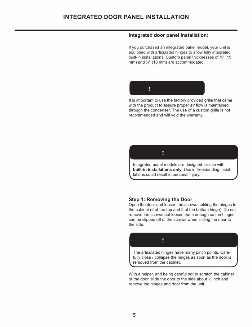
Integrated door panel installation:
Step 1: Removing the DoorOpen the door and loosen the screws holding the hinges to the cabinet (2 at the top and 2 at the bottom hinge). Do not remove the screws but loosen them enough so the hinges can be slipped off of the screws when sliding the door to the side.
With a helper, and being careful not to scratch the cabinet or the door, slide the door to the side about 1⁄2 inch and remove the hinges and door from the unit.
! WARNINGIntegrated panel models are designed for use with built-in installations only. Use in freestanding instal-lations could result in personal injury.
If you purchased an integrated panel model, your unit is equipped with articulated hinges to allow fully integrated built-in installations. Custom panel thicknesses of 5⁄8" (15 mm) and 3⁄4" (18 mm) are accommodated.
It is important to use the factory provided grille that came with the product to assure proper air flow is maintained through the condenser. The use of a custom grille is not recommended and will void the warranty.
! WARNINGThe articulated hinges have many pinch points. Care-fully close / collapse the hinges as soon as the door is removed from the cabinet.
5

INTEGRATED DOOR PANEL INSTALLATION
Integrated panel flush
with top and side of door.
Magnetic Gasket remove starting at a corner, grasp and pull away from the door.
Step 3: Cut and drill the integrated panelDepending on your model cut the integrated door panel to the dimensions shown in Figures 19 to 22. The window cut out is for glass door models only. If your appliance has a lock also drill the lock hole in the panel, see Figure 25.
Integrated panel to be centered on width of door.
Figure 24
Holes in gasket
retainer.
Figure 24a
Step 2: Remove the door gasketWith the door laying on a flat surface and starting at a corner of the door remove the magnetic door gasket from the interior side of the door, see Figure 25. Set the gasket aside on a flat surface.
There are 10 holes in the gasket retainer extrusions, (3 on each side and 2 at the top and bottom which are used to fasten the panel to the front of the door. The screws are provided in the literature pack along with the door lock, which is provided on certain models.
Loosen (do not remove ) these 2 phillips head screws on the top and bottom hinges
! WARNINGUse extreme caution with the articulated hinges. The hinge is self closing and many pinch points exist prior to built-in installation. Do not remove the cabinet "Z" bracket from the top of the cabinet.
Figure 23bBottom of
door
"P" clamp and screw
Wire connectorsee Figure 6
Figure 23
Figure 23a
Cabinet "Z" Bracket
6

! CAUTION
INTEGRATED DOOR PANEL INSTALLATION
Material Type #10 Wood Screw Hardwood 1⁄8" (3.2 mm) Diameter. Pilot HoleSoftwood 7⁄64 (2.8 mm) Diameter. Pilot Hole
Table A
Weight of integrated door panel must not exceed 15 pounds (6.8 kg) for a solid door model or 10 pounds (4.5 kg) for a glass door model.
#10 x 1⁄2"screw
Step 4: Assemble the panel to the doorThe preferred method of attaching the panel to the door is to clamp the panel to the door so it cannot move while drilling the screw pilot holes. Use bar clamps or "C" clamps with pads on the clamping surfaces that will not mar the panel or the door. The custom integrated panel should be flush with the top of the door and centered along the width of the door. See Figure 24a. Drill holes through the gasket extrusion using the 10 holes as pilot holes. Use the drill size from the chart in Table "A", being careful not to drill through the front surface of the panel. If the integrated panel is thinner than 5⁄8" (16 mm) thick shorter screws will have to be obtained. Fasten the panel to the door with the 10 screws provided in the literature pack. (See Figure 25a). Remove the clamps and replace the gasket in the gasket extrusion channels of the door. Some force may be required to seat the gasket into the channels. Be sure the gasket corners are seated properly.
A
A
B
B
C
C
D
D
8
8
7
7
6
6
5
5
4
4
3
3
2
2
1
1
PANEL-WOOD
DO NOT SCALE DRAWING
24 PanelSHEET 1 OF 1
UNLESS OTHERWISE SPECIFIED:
SCALE: 1:5 WEIGHT:
REVDWG. NO.
DSIZE
TITLE:
NAME DATE
COMMENTS:
Q.A.
MFG APPR.
ENG APPR.
CHECKED
DRAWN
FINISH
MATERIAL
INTERPRET GEOMETRICTOLERANCING PER:
DIMENSIONS ARE IN INCHESTOLERANCES:FRACTIONALANGULAR: MACH BEND TWO PLACE DECIMAL THREE PLACE DECIMAL
APPLICATION
USED ONNEXT ASSY
PROPRIETARY AND CONFIDENTIAL
THE INFORMATION CONTAINED IN THISDRAWING IS THE SOLE PROPERTY OF<INSERT COMPANY NAME HERE>. ANY REPRODUCTION IN PART OR AS A WHOLEWITHOUT THE WRITTEN PERMISSION OF<INSERT COMPANY NAME HERE> IS PROHIBITED.
Counter bore lock hole
on back side.
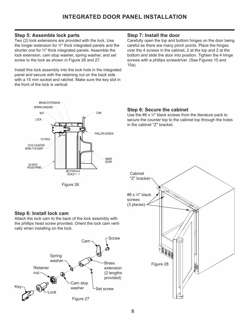
Figure 25 - Back of Panel
1⁄2" (13 mm) diameter drill through door panel, from other side 13⁄16" (20.5 mm) counter bore, 7⁄16" (11 mm) deep.
Hinge side of door
Figure 25a
7
Cabinet"Z" bracket
#8 x 3⁄4" black screws (3 places)
Figure 28
Step 7: Install the doorCarefully open the top and bottom hinges on the door being careful as there are many pinch points. Place the hinges over the 4 screws in the cabinet, 2 at the top and 2 at the bottom and slide the door into position. Tighten the 4 hinge screws with a phillips screwdriver. (See Figures 15 and 15a).
SECTION A-A SCALE 1 : 1
LOCK
NUT
BRASS EXTENSION
CAM
PHILLIPS SCREW
13/16 COUNTERBORE 7/16 DEEP
1/2 HOLE
3/4 INCHWOOD PANEL
SPRING WASHER
INNERDOOR
Step 8: Secure the cabinetUse the #8 x 3⁄4" black screws from the literature pack to secure the counter top to the cabinet top through the holes in the cabinet "Z" bracket.
INTEGRATED DOOR PANEL INSTALLATION
Figure 27
Step 6: Install lock camAttach the lock cam to the back of the lock assembly with the phillips head screw provided. Orient the lock cam verti-cally when installing on the lock.
Cam stopwasher
Springwasher
Cam
Set screwLock
Key
Retainernut
Screw
Brass extension(2 lengths provided)
Step 5: Assemble lock partsTwo (2) lock extensions are provided with the lock. Use the longer extension for 3⁄4" thick integrated panels and the shorter one for 5⁄8" thick integrated panels. Assemble the lock extension, cam stop washer, spring washer, and set screw to the lock as shown in Figure 26 and 27.
Install this lock assembly into the lock hole in the integrated panel and secure with the retaining nut on the back side with a 15 mm socket and ratchet. Make sure the key slot in the front of the lock is vertical.
Figure 26
8