Owners Guide Front Cover - Caithness Windfarms Guide.pdf · SM0228-01 Operating Guide R9000 Serial...
20
Owners Guide Ref Number: 0150-AA-00694
Transcript of Owners Guide Front Cover - Caithness Windfarms Guide.pdf · SM0228-01 Operating Guide R9000 Serial...

Owners
Guide
Ref Number: 0150-AA-00694

Operating Guide
Evance R9000
Serial Numbers Starting 0150

SM0228-01 Operating Guide R9000 Serial Numbers Starting 0150 2 of 11 Evance operates a one-live-source electronic document control system. Consequently all paper copies should be considered uncontrolled. Revisions are denoted in the document filename printed above and are available at www.evancewind.com
Operating Guide for the Evance R9000 Wind Turbine
Contents
1. Your Evance wind turbine system 2 How your turbine works 3. Starting up and shutting down your system 4. Inverter status 5. Reading the meter 6. Maintenance 7. What to do if there is a problem 8. Specifications

SM0228-01 Operating Guide R9000 Serial Numbers Starting 0150 3 of 11 Evance operates a one-live-source electronic document control system. Consequently all paper copies should be considered uncontrolled. Revisions are denoted in the document filename printed above and are available at www.evancewind.com
1. Your Evance wind turbine system The turbine system will normally be based on the following 10 elements:-
• The turbine Item A
• The tower Item B
• A turbine switch box Item C
• A power cable connecting the turbine to the electrical panel Item D
• A rectifier box Item E
• Inverter/s Item F
• Energy meter Item G
• A fuse box Item H
• A wind system/mains isolator Item I
• A wind turbine isolator Item J
Figure 1 Typical Single Phase Installation
A
B
C
D
F
E
H
G
I
J

SM0228-01 Operating Guide R9000 Serial Numbers Starting 0150 Evance operates a one-live-source electronic docdenoted in the document filename printed above
2. How your turbine works Your Evance R9000 is a 5kW upwind turbine whichand are turned into the wind using a tail vane (see figure 2.1).
The turbine starts generating in a wind speed ofmachine has a survival wind speed of 60high-efficiency generator. The R9000 is equipped with a patented speed regulating system, Reactive Pitchautomatically pitches the blades to shed excess The turbine is designed to be mounted on a series of The brake control switch, located at the braking system. The wind turbine produces alternating current (AC) electricity, which varies in both frequency and voltage as the turbine changes speed. The AC electricity is fed down a cable in the tower and through the underground power cable to an electrical equipment panel. The electrical equipment panel (figure 1) includes a wind turbine isolator (item J) and a rectifier box (item E) where the variable alternating current is turned into direct current range of 0Vdc to 470Vdc.
Tail vane
Serial Numbers Starting 0150 ocument control system. Consequently all paper copies should be consove and are available at www.evancewind.com
turbine works
R9000 is a 5kW upwind turbine which means that the blades are placed at the front and are turned into the wind using a tail vane (see figure 2.1).
in a wind speed of around 3 metres/second (6.7mph).has a survival wind speed of 60 metres/second (134mph) and incorporates a
The R9000 is equipped with a patented speed regulating system, Reactive Pitchautomatically pitches the blades to shed excess power and control turbine speed.
is designed to be mounted on a series of Evance approved tower systems.
The brake control switch, located at the tower base, can be used to apply and release the
The wind turbine produces alternating current (AC) electricity, which varies in both frequency and voltage as the turbine changes speed. The AC electricity is fed down a cable in the tower nd through the underground power cable to an electrical equipment panel.
The electrical equipment panel (figure 1) includes a wind turbine isolator (item J) and a rectifier box (item E) where the variable alternating current is turned into direct current
Figure 2.1 R9000 Turbine
4 of 11 onsidered uncontrolled. Revisions are
means that the blades are placed at the front
around 3 metres/second (6.7mph). Your metres/second (134mph) and incorporates a patented
The R9000 is equipped with a patented speed regulating system, Reactive PitchTM, which power and control turbine speed.
Evance approved tower systems.
tower base, can be used to apply and release the
The wind turbine produces alternating current (AC) electricity, which varies in both frequency and voltage as the turbine changes speed. The AC electricity is fed down a cable in the tower nd through the underground power cable to an electrical equipment panel.
The electrical equipment panel (figure 1) includes a wind turbine isolator (item J) and a rectifier box (item E) where the variable alternating current is turned into direct current (DC) in the
Turbine
generator and
blades
SM0228-01 Operating Guide R9000 Serial Numbers Starting 0150 5 of 11 Evance operates a one-live-source electronic document control system. Consequently all paper copies should be considered uncontrolled. Revisions are denoted in the document filename printed above and are available at www.evancewind.com
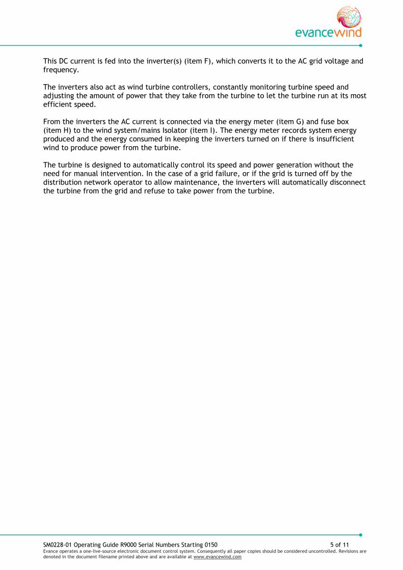
This DC current is fed into the inverter(s) (item F), which converts it to the AC grid voltage and frequency. The inverters also act as wind turbine controllers, constantly monitoring turbine speed and adjusting the amount of power that they take from the turbine to let the turbine run at its most efficient speed. From the inverters the AC current is connected via the energy meter (item G) and fuse box (item H) to the wind system/mains Isolator (item I). The energy meter records system energy produced and the energy consumed in keeping the inverters turned on if there is insufficient wind to produce power from the turbine. The turbine is designed to automatically control its speed and power generation without the need for manual intervention. In the case of a grid failure, or if the grid is turned off by the distribution network operator to allow maintenance, the inverters will automatically disconnect the turbine from the grid and refuse to take power from the turbine.
SM0228-01 Operating Guide R9000 Serial Numbers Starting 0150 6 of 11 Evance operates a one-live-source electronic document control system. Consequently all paper copies should be considered uncontrolled. Revisions are denoted in the document filename printed above and are available at www.evancewind.com
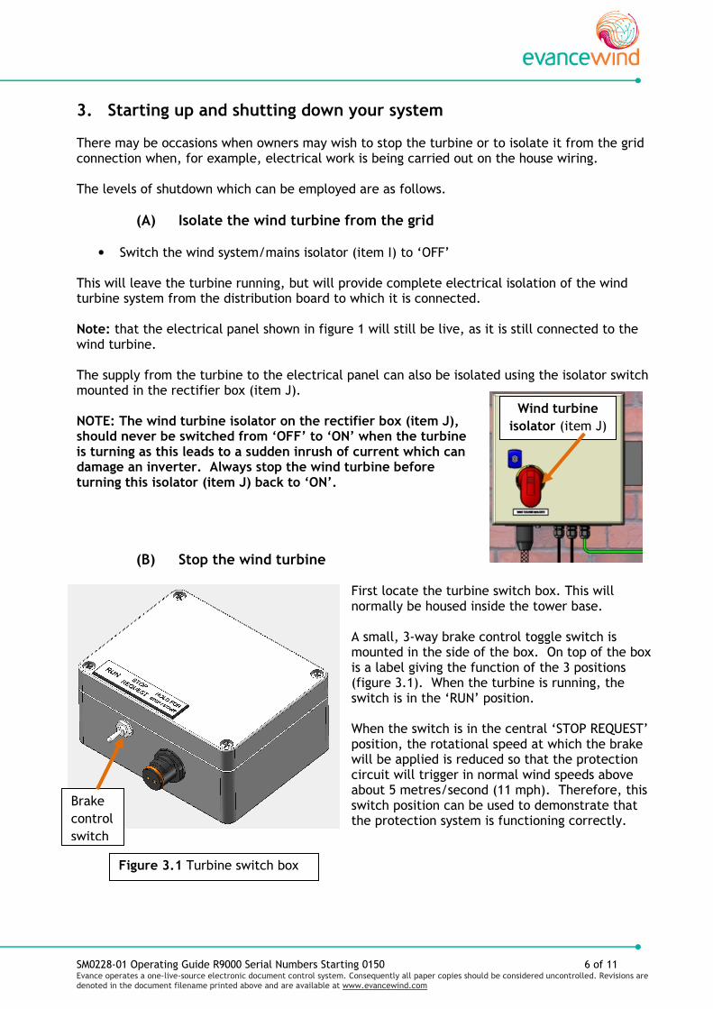
3. Starting up and shutting down your system There may be occasions when owners may wish to stop the turbine or to isolate it from the grid connection when, for example, electrical work is being carried out on the house wiring. The levels of shutdown which can be employed are as follows.
(A) Isolate the wind turbine from the grid
• Switch the wind system/mains isolator (item I) to ‘OFF’ This will leave the turbine running, but will provide complete electrical isolation of the wind turbine system from the distribution board to which it is connected. Note: that the electrical panel shown in figure 1 will still be live, as it is still connected to the wind turbine. The supply from the turbine to the electrical panel can also be isolated using the isolator switch mounted in the rectifier box (item J). NOTE: The wind turbine isolator on the rectifier box (item J), should never be switched from ‘OFF’ to ‘ON’ when the turbine is turning as this leads to a sudden inrush of current which can damage an inverter. Always stop the wind turbine before turning this isolator (item J) back to ‘ON’.
(B) Stop the wind turbine
First locate the turbine switch box. This will normally be housed inside the tower base. A small, 3-way brake control toggle switch is mounted in the side of the box. On top of the box is a label giving the function of the 3 positions (figure 3.1). When the turbine is running, the switch is in the ‘RUN’ position. When the switch is in the central ‘STOP REQUEST’ position, the rotational speed at which the brake will be applied is reduced so that the protection circuit will trigger in normal wind speeds above about 5 metres/second (11 mph). Therefore, this switch position can be used to demonstrate that the protection system is functioning correctly.
Wind turbine
isolator (item J)
Figure 3.1 Turbine switch box
Brake
control
switch

SM0228-01 Operating Guide R9000 Serial Numbers Starting 0150 7 of 11 Evance operates a one-live-source electronic document control system. Consequently all paper copies should be considered uncontrolled. Revisions are denoted in the document filename printed above and are available at www.evancewind.com
(C) Enforcing a turbine shutdown
Move the 3-way brake control switch across to the ‘HOLD FOR STOP/START’ position and hold it there for 2-3 seconds until a whistle can be heard at the top of the tower or the rotor stops turning. Immediately release the switch. This operation will apply the brake and the turbine will stop.
(D) Start the wind turbine
To start the turbine up again move the 3-way brake control switch back to the ‘HOLD FOR STOP/START’ position and hold for about 2-3 seconds, or until you hear the whistle, then immediately release the switch, this releases the brake.
Note: That in light winds the turbine may take some time to start moving.
When the brake has released, move the 3-way brake control switch to the ‘RUN’ position. If the switch is left at the central ‘STOP REQUEST’ position the turbine will automatically stop itself when it reaches around 160 rpm.
Tip: The protection system obtains its power from the wind turbine itself and does not rely on batteries to function. However, whenever you enforce a stop (using ‘HOLD FOR STOP/START’), or release the brake to allow the wind turbine to start, the circuit uses power from 2 x 9V batteries (PP3) that are located within the turbine switch box. Tip: Power is drawn from these batteries only when you move the switch to the ‘HOLD FOR STOP/START’ position so they should last for several years. The service teams will check the batteries and exchange them as part of the annual inspection.

SM0228-01 Operating Guide R9000 Serial Numbers Starting 0150 8 of 11 Evance operates a one-live-source electronic document control system. Consequently all paper copies should be considered uncontrolled. Revisions are denoted in the document filename printed above and are available at www.evancewind.com
4. Inverter status The Inverter/s is located on the electrical equipment panel (figure 1 item F) Three coloured LED’s are provided on each inverter panel (figure 4.1) to indicate its status. There is also an LCD display which shows details of turbine output and inverter status. If the inverter is showing a single red light, this indicates that it has switched off. This is usually due to the grid supply either being switched off, or its voltage or frequency having moved outside of the allowable limits. The inverter LCD display should be displaying an error code which will describe the problem. (See the SMA Inverter Operator Manual supplied with your system for details of error codes).
Table 1: What to expect to see on the inverter and electrical meters
Wind condition Approximate speed of wind turbine
Expected state of the lights on the inverters
Still Turbine stationary or rotating at less than 50 rpm
After one hour of very low wind speed, or a still wind, the inverters will switch themselves off. All lights will go out.
Light winds that are sufficient to turn the wind turbine only slowly
Turbine rotating at 50 - 100 rpm
The inverters will begin to come to life once the turbine reaches around 60 rpm. All three lights will come on, faintly at first then more brightly as the turbine gains speed.
Winds above 3 m/s
Turbine rotating at 120 rpm or more
As the turbine speed increases the inverters will begin an initialization period. During this the green light will start flashing and other lights will go off. The inverters are waiting for the right wind and grid conditions to be able to deliver power. When the inverter has synchronised with the grid and the reconnection time has elapsed the inverters will come on-line. The green light will stop flashing and become constantly on.
All other normal wind conditions
The turbine will vary speed according to the available wind. In strong winds the turbine will control its speed by varying the blade pitch. There is a distinct change in the aerodynamic sound of the wind turbine when this occurs.
The green light will be constantly on.
Coloured LED’s
LCD display
Green LED
Figure 4.1 Inverter panel label
SM0228-01 Operating Guide R9000 Serial Numbers Starting 0150 9 of 11 Evance operates a one-live-source electronic document control system. Consequently all paper copies should be considered uncontrolled. Revisions are denoted in the document filename printed above and are available at www.evancewind.com
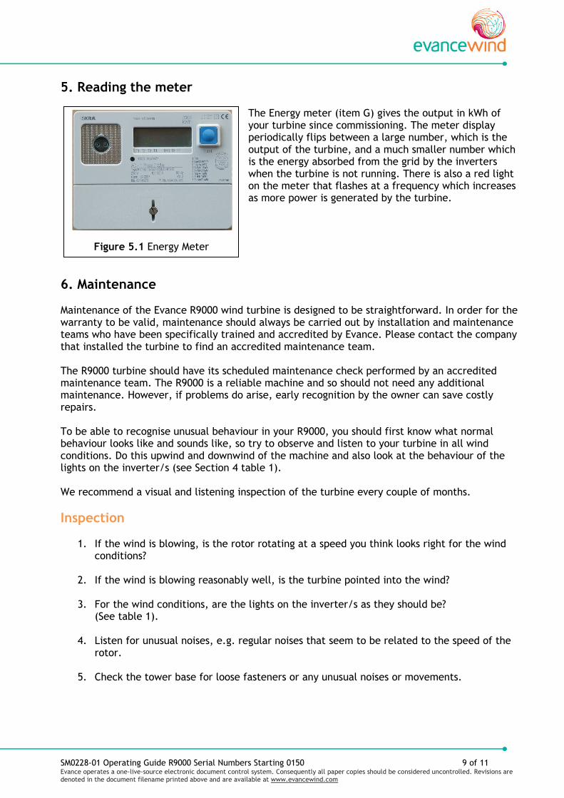
Figure 5.1 Energy Meter
5. Reading the meter The Energy meter (item G) gives the output in kWh of your turbine since commissioning. The meter display periodically flips between a large number, which is the output of the turbine, and a much smaller number which is the energy absorbed from the grid by the inverters when the turbine is not running. There is also a red light on the meter that flashes at a frequency which increases as more power is generated by the turbine.
6. Maintenance Maintenance of the Evance R9000 wind turbine is designed to be straightforward. In order for the warranty to be valid, maintenance should always be carried out by installation and maintenance teams who have been specifically trained and accredited by Evance. Please contact the company that installed the turbine to find an accredited maintenance team. The R9000 turbine should have its scheduled maintenance check performed by an accredited maintenance team. The R9000 is a reliable machine and so should not need any additional maintenance. However, if problems do arise, early recognition by the owner can save costly repairs. To be able to recognise unusual behaviour in your R9000, you should first know what normal behaviour looks like and sounds like, so try to observe and listen to your turbine in all wind conditions. Do this upwind and downwind of the machine and also look at the behaviour of the lights on the inverter/s (see Section 4 table 1). We recommend a visual and listening inspection of the turbine every couple of months.
Inspection
1. If the wind is blowing, is the rotor rotating at a speed you think looks right for the wind conditions?
2. If the wind is blowing reasonably well, is the turbine pointed into the wind?
3. For the wind conditions, are the lights on the inverter/s as they should be?
(See table 1).
4. Listen for unusual noises, e.g. regular noises that seem to be related to the speed of the rotor.
5. Check the tower base for loose fasteners or any unusual noises or movements.

SM0228-01 Operating Guide R9000 Serial Numbers Starting 0150 10 of 11 Evance operates a one-live-source electronic document control system. Consequently all paper copies should be considered uncontrolled. Revisions are denoted in the document filename printed above and are available at www.evancewind.com
Be careful not to confuse turbine noises with background noises on windy days. In very light winds at low rotational speeds there is often a once per revolution tapping sound from the machine. This is quite normal and is due to the blades settling under the force of gravity, with the force on each blade reversing as it goes over top dead centre and bottom dead centre positions. If however there are any unusual or loud noises which could potentially indicate a problem, the Evance installer who supplied the machine should be contacted immediately.
7. What to do if there is a problem Warranty and maintenance questions should be directed to your local reseller or installer. If you have any concerns about the operation of your wind turbine, please contact them with:
1. Accurate description of the symptoms.
2. Wind conditions when symptoms occur.
3. How long the symptoms have been occurring.
4. If the symptoms have become worse. Your reseller or installer can advise if a problem is potentially serious, or if it can be left until the next maintenance visit.

SM0228-01 Operating Guide R9000 Serial Numbers Starting 0150 11 of 11 Evance operates a one-live-source electronic document control system. Consequently all paper copies should be considered uncontrolled. Revisions are denoted in the document filename printed above and are available at www.evancewind.com
8. Specifications
SM0146-06 R9000 Warranty Statement Page 1 of 1 Evance operates a one-live-source electronic document control system. Consequently all paper copies should be considered uncontrolled. Revisions are denoted in the document filename printed above and are available at www.evancewind.com. Evance Wind Turbines Ltd is registered in England. Company No.03885429. VAT Registration No. GB827750313. Registered Office: Unit 6 Weldon Road, Loughborough, Leicestershire, LE11 5RN.
R9000 Wind Turbine 5 Year Warranty At Evance, we take great care to ensure all our products are designed and manufactured to international standards to give the customer a long and satisfying ownership experience. To give you peace of mind, Evance offers a warranty with the following terms and conditions. If, due to a defect in design or manufacture, the wind turbine fails during the period of 5 years after the date of commissioning, then Evance will, at its option, repair or provide a replacement of the wind turbine or any defective component concerned on a parts only exchange basis provided that : • a valid Warranty Certificate was returned to Evance by the Installer within 10 working days of;
and received by Evance within 1 month of; the commissioning date
• all installation, commissioning, servicing and maintenance was carried out and provided by an Evance Certified Installer in accordance with Evance Installation and Commissioning Procedures
• the turbine was and always has been serviced every 12 months according to Evance Service & Maintenance Procedures, including any scheduled part replacements
• the defect becomes apparent within 13 months of the date of Commissioning, or within 13 months of the date when it last received routine maintenance
• the turbine and any associated system in which it is incorporated was taken out of service immediately on the defect becoming apparent to ensure that no further damage was caused
• Evance has the opportunity to examine faulty parts to ascertain to its satisfaction that they are defective due to faulty design or manufacture
Evance shall not be liable for any costs or replacement parts if: • the Customer makes any further use of the turbine after becoming aware of any defect or
damage, unless Evance’s prior written consent to such further use is obtained
• the defect or damage arises from improper installation (whether carried out by an Evance Certified Installer or not), storage, operation, failure to comply with Evance instructions and advice, accidental damage, misuse, lightning, force majeure or modifications or alterations which are carried out without the prior written consent of Evance
• the defect or damage arises from failure by the Installer to comply with good trade practice
• the defect or damage is caused by poor siting of the turbine, including sites with excessive turbulence or sites which experience annual mean wind speeds greater than 8.5m/s (19 mph), or the damage arises from exposure to peak wind speeds in excess of 60m/s (134mph)
• the defect or damage arises as a result of fair wear and tear
• the defect or damage arises from the use of the turbine in connection with equipment or parts that have not been approved by Evance, including towers and inverters, or failure of these parts and their consequences.
Any repaired or replacement Products shall be guaranteed on these terms for the unexpired portion of the warranty period.
This warranty does not apply to any costs of labour or transport, whether for investigation, repair, replacement or any other purpose (your Installer should cover these costs for warranty claims).
This Warranty applies only to the Evance wind turbine (including blades) supplied to the Customer. It does not apply to ancillary equipment not manufactured by Evance, such as cables, towers and inverters (you should be given the Manufacturers Warranties for these parts by your Installer).
This warranty does not affect the statutory rights of the Customer.
SM0109-06 Warranty Certificate Page 1 of 1 Evance operates a one-live-source electronic document control system. Consequently all paper copies should be considered uncontrolled.
Revisions are denoted in the document filename printed above and are available at www.evancewind.com. Evance Wind Turbines Ltd is registered in England. Company No.03885429. VAT Registration No. GB827750313. Registered Office: Unit 6 Weldon Road, Loughborough, Leicestershire, LE11 5RN
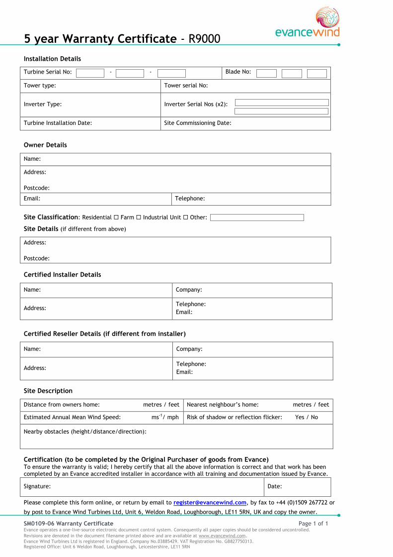
5 year Warranty Certificate - R9000 Installation Details
Turbine Serial No: - - Blade No:
Tower type: Tower serial No:
Inverter Type:
Inverter Serial Nos (x2):
Turbine Installation Date: Site Commissioning Date:
Owner Details
Name:
Address:
Postcode:
Email: Telephone:
Site Classification: Residential Farm Industrial Unit Other:
Site Details (if different from above)
Address:
Postcode:
Certified Installer Details
Name: Company:
Address: Telephone:
Email:
Certified Reseller Details (if different from installer)
Name: Company:
Address: Telephone:
Email:
Site Description
Distance from owners home: metres / feet Nearest neighbour’s home: metres / feet
Estimated Annual Mean Wind Speed: ms-1/ mph Risk of shadow or reflection flicker: Yes / No
Nearby obstacles (height/distance/direction):
Certification (to be completed by the Original Purchaser of goods from Evance) To ensure the warranty is valid; I hereby certify that all the above information is correct and that work has been completed by an Evance accredited installer in accordance with all training and documentation issued by Evance.
Signature: Date:
Please complete this form online, or return by email to [email protected], by fax to +44 (0)1509 267722 or
by post to Evance Wind Turbines Ltd, Unit 6, Weldon Road, Loughborough, LE11 5RN, UK and copy the owner.

@mGert¡f¡cate of Approval
M¡crogeneration
Evance W¡nd Turbines LimitedUnit 6 Weldon Road
LoughboroughLeicestershire LE11 5RN
Has complied with the requirements identified in
MCS 010-1.5 Generic Factory Production Control (FPC) Requirementsand
MCS 006-1.5 Product Gertification requirements forMicro and Small Wind Turbines
and is authorised to use the BRE Global Mark and theMicrogeneration scheme mark on the following Product(s) and
associated stationery and publications:
bannd Ao¡11
David Gallfor and on behalf of BRE Global
Certificate No: MCS WT0039
lssue Number: 1
Valid From: l5 July 2010
breglobotBRE Global Limited, Watford, WD25 gXX T: +44 (0)'1923 664100 F: +44 (0)1923 664910 W: www.greenbooklive.com
This certificate remains the property of BRE Global Ltd and is issued subject to terms and conditions. lt is maintained and held in forcethrough annual review and verification. To check the authenticity of this cert¡f¡cate, please visit 9444.g@þ9!!!ry or contact us.
APPROVED PRODUCT
e@
Model Description Reference No.
Evance R9000 Small Wind Turbine MCS WT0039/01
8F949 Rev 2 Paoe I of I @ BRE Global Ltd. 2009

CS-20 Issue 1 Maintenance Schedule and Record August 2010 1 of 3 Evance operates a one-live-source electronic document control system. Consequently all paper copies should be considered uncontrolled.
Revisions are denoted in the document filename printed above and are available at www.evancewind.com.
Evance R9000 Maintenance Schedule
Introduction This schedule provides details of the maintenance requirements for the Evance R9000 wind turbine. Work on the turbine should only be carried out by fully trained personnel who are familiar with the machine and with Evance maintenance procedures. Maintenance Intervals The R9000 turbine and supporting structure require annual maintenance checks. For newly installed machines Evance may wish to carry out an additional check after 3-6 months of running, dependent on turbine location and service. Maintenance Procedures The following areas will be covered during the annual maintenance check.
Tower and Supporting Structure Integrity of foundations and support structure, bolt tightening torques, integrity of anti corrosive coatings. Tension and condition of support guys where appropriate.
Core Unit and Yaw System Check & record torque tightening of all fasteners on Yaw box and main generator unit. Re-lubricate yaw bearing. Check torque tightening of tail boom assembly. Check and rectify all surface coatings and check location and condition of anti vibration materials.
Pitch System Check, record and adjust blade pitch setting and pitch pre-load. Check integrity of pitch bearings. Check & record torque tightening of all fasteners. Visual inspection of spider connections.
Blades Clean blades and carry out a thorough visual check of condition.
Electrical Equipment & Connections Visual check of all cabling and connections for evidence of chafing, looseness or degradation. Test brake operation and setting levels. Check attachment of brake control unit. Check tightness of main cable support clip. Check main power cable for evidence of wind-up, disconnect and rectify if necessary. Check attachment and integrity of lightning protection equipment.
Re-Commissioning Following all maintenance work the turbine should be run to check normal operation of the automatic brake system and grid connection hardware.
Maintenance & Repairs are to be performed by trained personnel only. In case of any uncertainty regarding the contents of this specification please contact Evance Wind Turbines Ltd.

CS-20 Issue 1 Maintenance Schedule and Record August 2010 2 of 3 Evance operates a one-live-source electronic document control system. Consequently all paper copies should be considered uncontrolled.
Revisions are denoted in the document filename printed above and are available at www.evancewind.com.
Maintenance Completed
kWh Generated:
Date:
Service signature:
Maintenance Visit 9
9th Year
Maintenance Completed
kWh Generated:
Date:
Service signature:
Maintenance Visit10
10th Year
Maintenance Completed
kWh Generated: Date:
Service signature:
Maintenance Visit 1
1st Year
Maintenance Completed
kWh Generated:
Date:
Service signature:
Maintenance Visit 2
2nd Year
Maintenance Completed
kWh Generated:
Date:
Service signature:
Maintenance Visit 3
3rd Year
Maintenance Completed
kWh Generated:
Date:
Service signature:
Maintenance Visit 4
4th Year
Maintenance Completed
kWh Generated:
Date:
Service signature:
Maintenance Visit 5
5th Year
Maintenance Completed
kWh Generated:
Date:
Service signature:
Maintenance Visit 6
6th Year
Maintenance Completed
kWh Generated:
Date:
Service signature:
Maintenance Visit 7
7th Year
Maintenance Completed
kWh Generated:
Date:
Service signature:
Maintenance Visit 8
8th Year
Customer:
Turbine Serial Number: Date:
Installer signature:
Turbine
Commissioned
Maintenance of your Wind Turbine according to the approved schedule is required to ensure that your warranty coverage
remains in force.

CS-20 Issue 1 Maintenance Schedule and Record August 2010 3 of 3 Evance operates a one-live-source electronic document control system. Consequently all paper copies should be considered uncontrolled.
Revisions are denoted in the document filename printed above and are available at www.evancewind.com.
Maintenance Completed
kWh Generated:
Date:
Service signature:
Maintenance Visit 20
20th Year
Maintenance Completed
kWh Generated:
Date:
Service signature:
Maintenance Completed
kWh Generated:
Date:
Service signature:
Maintenance Visit 12
12th Year
Maintenance Completed
kWh Generated:
Date:
Service signature:
Maintenance Visit 13
13th Year
Maintenance Completed
kWh Generated:
Date:
Service signature:
Maintenance Visit 14
14th Year
Maintenance Completed
kWh Generated:
Date:
Service signature:
Maintenance Visit15
15th Year
Maintenance Completed
kWh Generated:
Date:
Service signature:
Maintenance Visit 16
16th Year
Maintenance Completed
kWh Generated:
Date:
Service signature:
Maintenance Visit 17
17th Year
Maintenance Completed
kWh Generated:
Date:
Service signature:
Maintenance Visit 18
18th Year
Maintenance Completed
kWh Generated:
Date:
Service signature:
Maintenance Visit 19
19th Year
Maintenance Completed
kWh Generated:
Date:
Service signature:
Maintenance Visit 11
11th Year
Maintenance of your Wind Turbine according to the approved schedule is required to ensure that your warranty coverage
remains in force.