Owner’s Manual Power Take-Offs · Always refer to Chelsea catalogs, literature, and owner’s...
56
Bulletin HY25-1240-M1/US Owner’s Manual Power Take-Offs Effective: December 2008 Supersedes: HY25-1240-M1/US January 2008 230 Series 231 Series 236 Series 250 Series 270 Series 271 Series 800 Series 852 Series 885 Series
Transcript of Owner’s Manual Power Take-Offs · Always refer to Chelsea catalogs, literature, and owner’s...

Bulletin HY25-1240-M1/US
Owner’s Manual Power Take-Offs
Effective: December 2008Supersedes: HY25-1240-M1/US January 2008
230 Series231 Series236 Series
250 Series270 Series 271 Series
800 Series852 Series885 Series

Parker Hannifin CorporationChelsea Products DivisionOlive Branch, MS 38654 USA
Parker Hannifin CorporationChelsea Products DivisionOlive Branch, MS 38654 USA
Parker Hannifin CorporationChelsea Products DivisionOlive Branch, MS 38654 USA
FAILURE OR IMPROPER SELECTION OR IMPROPER USE OF THE PRODUCTS AND/OR SYSTEMS DESCRIBED HEREIN OR RELATED ITEMS CAN CAUSE DEATH, PERSONAL INJURY AND PROPERTY DAMAGE.
This document and other information from Parker Hannifin Corporation, its subsidiaries and authorized distributors provide product and/or system options for further investigation by users having technical expertise. It is important that you analyze all aspects of your application and review the information concerning the product or system in the current product catalog. Due to the variety of operating conditions and applications for these products or systems, the user, through its own analysis and testing, is solely responsible for making the final selection of the products and systems and assuring that all performance, safety and warning requirements of the application are met.
The products described herein, including without limitation, product features, specifications, designs, availability and pricing, are subject to change by Parker Hannifin Corporation and its subsidiaries at any time without notice.
WARNING
The items described in this document are hereby offered for sale by Parker Hannifin Corporation, its subsidiaries or its authorized distributors. This offer and its acceptance are governed by the provisions stated in the "Offer of Sale".
Offer of Sale
© Copyright 2008, Parker Hannifin Corporation, All Rights Reserved
II
The Chelsea® Power Take-Off or its components shipped with this owner’s manual may be manufactured under one or more of the following U.S. patents:4610175 5228355 4597301 5645363 6151975 6142274 6260682 7159701 B2Other patents pending.
Patent Information
Bulletin HY25-1240-M1/US Owner’s ManualPowershift P.T.O.s
Parker Hannifin CorporationChelsea Products DivisionOlive Branch, MS 38654 USA
Parker Hannifin CorporationChelsea Products DivisionOlive Branch, MS 38654 USA
Contents
General Information
Safety Information .............................................................................................................................................................. 1-2
Direct Mount Pump Support Recommendations ............................................................................................................... 3
Foreword ............................................................................................................................................................................ 4
Chelsea P.T.O. Safety Label Installation ............................................................................................................................. 4
Function of Auxiliary Power Shafts .................................................................................................................................... 6
Spicer® Universal Joint Engineering Data .......................................................................................................................... 7
Installation Instructions
Dodge/Sterling Overview ................................................................................................................................................... 8
2007-2008 Dodge/Sterling Heavy Duty Chassis Cab P.T.O. .............................................................................................. 9-12
Mounting 230, 236, 250, 270, 800, 852 and 885 P.T.O. to Transmission ........................................................................... 13-14
Mounting 231 and 271 P.T.O. to Transmission ................................................................................................................... 15-16
Checking Backlash ............................................................................................................................................................ 17
Hose Connection Illustrations ............................................................................................................................................ 18-19
GMT P.T.O. Connectors ...................................................................................................................................................... 20-21
Shifter Component Installation Sketch for 270, 271, 800 and 852 Series (Allison)............................................................ 22
Shifter Component Installation Sketch for 270, 271, 800 and 852 Series (Allison 1000, 2000/2400 Series) .................... 23
Electronic Overspeed Control Installation Sketch for 270, 271, 800 and 852 Series (Allison) ........................................... 24
Electric Overspeed Control Installation Sketch for 270, 271, 800 and 852 Series (Allison 1000, 2000/2400 Series) ....... 25
Installation Sketch 12 and 24 Volt with Speed Limiter, 270 Series/AISIN Automatic Transmission (models A443, A445 & A450-43LE) ................................................................................................................................... 26
Manual Air Shift Component Installation Sketch for 230/231 & 236 Series ....................................................................... 27
Shifter Component Installation Sketch for 230/231 & 236 Series without E.O.C. .............................................................. 28
Shifter Component Installation Sketch for 230/231 & 236 Series w/E.O.C. ....................................................................... 29
Shifter Component Installation Sketch for 230/231 Series without E.O.C. (Allison 1000, 2000/2400 Series) .................... 30
Shifter Component Installation Sketch for 230/231 Series w/E.O.C. (Allison 1000, 2000/2400 Series) ............................ 31
Air Shift Component Installation Sketch for 230/231 Series with Manual Air Valve (Allison 1000, 2000/2400 Series) ...... 32
Installation Sketch for 250 Series without Speed Limiter ................................................................................................... 33
Shifter Component Installation Sketch for 885 Series w/E.O.C. ......................................................................................... 34
Shifter Component Installation Sketch for 885 Series without E.O.C. ................................................................................ 35
P.T.O./Combo Valve Installation Sketch, 270/271 Series (SK-428) .................................................................................... 36
P.T.O./Combo Valve Installation Sketch, 230/231 & 236 Series (SK-429) .......................................................................... 37
Pressure Lube Installation Sketch for 885 Series .............................................................................................................. 38
Indicator Light Installation .................................................................................................................................................. 38
Dash Drilling Template for 6 & 8 Bolt Air Shift for Williams Valve ....................................................................................... 39-40
P.T.O. Openings for Automatic Transmissions .................................................................................................................... 41-43
Circuit Check for Powershift P.T.O. ..................................................................................................................................... 44
Rotatable Flange Torque Specifications ............................................................................................................................. 45
P.T.O. Shifting Procedure & Precautions ............................................................................................................................ 46
Power Take-Off Maintenance ............................................................................................................................................. 50
Offer of Sale ....................................................................................................................................................................... 51
III

Parker Hannifin CorporationChelsea Products DivisionOlive Branch, MS 38654 USA
Parker Hannifin CorporationChelsea Products DivisionOlive Branch, MS 38654 USA
Notes
IV

Bulletin HY25-1240-M1/US Owner’s ManualPowershift P.T.O.s
Parker Hannifin CorporationChelsea Products DivisionOlive Branch, MS 38654 USA
Parker Hannifin CorporationChelsea Products DivisionOlive Branch, MS 38654 USA
General Information
This symbol warns of possible personal injury.
These instructions are for your safety and the safety of the end user. Read them carefully until you understand them.
General Safety Information
To prevent injury to yourself and/or damage to the equipment:
■ Read carefully all owner’s manuals, service manuals, and/or other instructions.
■ Always follow proper procedures, and use proper tools and safety equipment.
■ Be sure to receive proper training.
■ Never work alone while under a vehicle or while repairing or maintaining equipment.
■ Always use proper components in applications for which they are approved.
■ Be sure to assemble components properly.
■ Never use worn-out or damaged components.
■ Always block any raised or moving device that may injure a person working on or under a vehicle.
■ Never operate the controls of the Power Take-Off or other driven equipment from any position that could result in getting caught in the moving machinery.
Proper Matching of P.T.O.
WARNING: A Power Take-Off must be properly matched to the vehicle transmission and to the auxiliary equipment being powered. An improperly matched Power Take-Off could cause severe damage to the vehicle transmission, the auxiliary driveshaft, and/or to the auxiliary equipment being powered. Damaged components or equipment could malfunction causing serious personal injury to the vehicle operator or to others nearby.
To avoid personal injury and/or equipment damage:
■ Always refer to Chelsea catalogs, literature, and owner’s manuals and follow Chelsea recommendations when selecting, installing, repairing, or operating a Power Take-Off.
■ Never attempt to use a Power Take-Off not specifically recommended by Chelsea for the vehicle transmission.
■ Always match the Power Take-Off’s specified output capabilities to the requirements of the equipment to be powered.
■ Never use a Power Take-Off whose range of speed could exceed the maximum.
Cold Weather Operation of Powershift P.T.O. WARNING: During extreme cold weather operation [32°F (0°C) and lower], a disengaged Powershift Power Take-Off can momentarily transmit high torque that will cause unexpected output shaft rotation. This is caused by the high viscosity of the transmission oil when it is extremely cold. As slippage occurs between the Power Take-Off clutch plates, the oil will rapidly heat up and the viscous drag will quickly decrease.
The Power Take-Off output shaft rotation could cause unexpected movement of the driven equipment resulting in serious personal injury, death, or equipment damage.
To avoid personal injury or equipment damage:
■ Driven equipment must have separate controls.
■ The driven equipment must be left in the disengaged position when not in operation.
■ Do not operate the driven equipment until the vehicle is allowed to warm up.
Safety Information
1
Bulletin HY25-1240-M1/US Owner’s ManualPowershift P.T.O.s
Parker Hannifin CorporationChelsea Products DivisionOlive Branch, MS 38654 USA
Parker Hannifin CorporationChelsea Products DivisionOlive Branch, MS 38654 USA
Parker Hannifin CorporationChelsea Products DivisionOlive Branch, MS 38654 USA
Parker Hannifin CorporationChelsea Products DivisionOlive Branch, MS 38654 USA
General Information
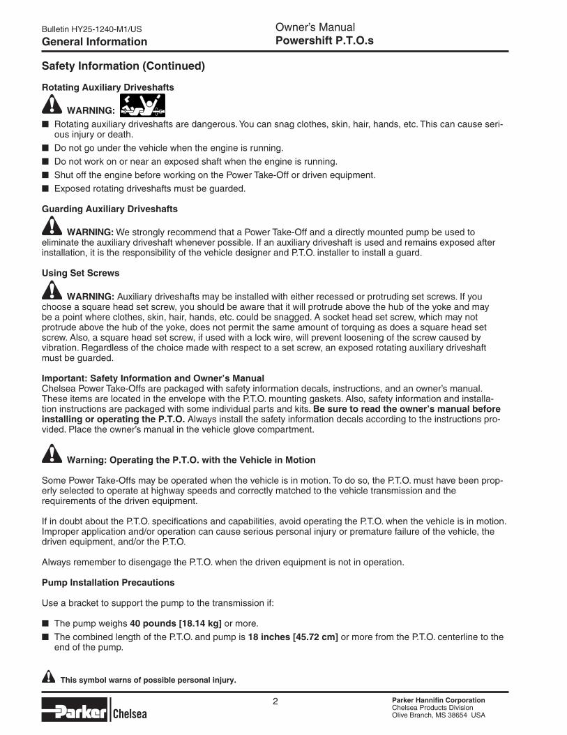
Rotating Auxiliary Driveshafts
WARNING:■ Rotating auxiliary driveshafts are dangerous. You can snag clothes, skin, hair, hands, etc. This can cause seri-
ous injury or death.
■ Do not go under the vehicle when the engine is running.
■ Do not work on or near an exposed shaft when the engine is running.
■ Shut off the engine before working on the Power Take-Off or driven equipment.
■ Exposed rotating driveshafts must be guarded.
Guarding Auxiliary Driveshafts
WARNING: We strongly recommend that a Power Take-Off and a directly mounted pump be used to eliminate the auxiliary driveshaft whenever possible. If an auxiliary driveshaft is used and remains exposed after installation, it is the responsibility of the vehicle designer and P.T.O. installer to install a guard.
Using Set Screws
WARNING: Auxiliary driveshafts may be installed with either recessed or protruding set screws. If you choose a square head set screw, you should be aware that it will protrude above the hub of the yoke and may be a point where clothes, skin, hair, hands, etc. could be snagged. A socket head set screw, which may not protrude above the hub of the yoke, does not permit the same amount of torquing as does a square head set screw. Also, a square head set screw, if used with a lock wire, will prevent loosening of the screw caused by vibration. Regardless of the choice made with respect to a set screw, an exposed rotating auxiliary driveshaft must be guarded.
Important: Safety Information and Owner’s ManualChelsea Power Take-Offs are packaged with safety information decals, instructions, and an owner’s manual. These items are located in the envelope with the P.T.O. mounting gaskets. Also, safety information and installa-tion instructions are packaged with some individual parts and kits. Be sure to read the owner’s manual before installing or operating the P.T.O. Always install the safety information decals according to the instructions pro-vided. Place the owner’s manual in the vehicle glove compartment.
Warning: Operating the P.T.O. with the Vehicle in Motion
Some Power Take-Offs may be operated when the vehicle is in motion. To do so, the P.T.O. must have been prop-erly selected to operate at highway speeds and correctly matched to the vehicle transmission and the requirements of the driven equipment.
If in doubt about the P.T.O. specifications and capabilities, avoid operating the P.T.O. when the vehicle is in motion. Improper application and/or operation can cause serious personal injury or premature failure of the vehicle, the driven equipment, and/or the P.T.O.
Always remember to disengage the P.T.O. when the driven equipment is not in operation.
Pump Installation Precautions
Use a bracket to support the pump to the transmission if:
■ The pump weighs 40 pounds [18.14 kg] or more.
■ The combined length of the P.T.O. and pump is 18 inches [45.72 cm] or more from the P.T.O. centerline to the end of the pump.
Safety Information (Continued)
This symbol warns of possible personal injury.
2
Parker Hannifin CorporationChelsea Products DivisionOlive Branch, MS 38654 USA
Parker Hannifin CorporationChelsea Products DivisionOlive Branch, MS 38654 USA
Bulletin HY25-1240-M1/US Owner’s ManualPowershift P.T.O.s
Parker Hannifin CorporationChelsea Products DivisionOlive Branch, MS 38654 USA
Parker Hannifin CorporationChelsea Products DivisionOlive Branch, MS 38654 USA
General Information
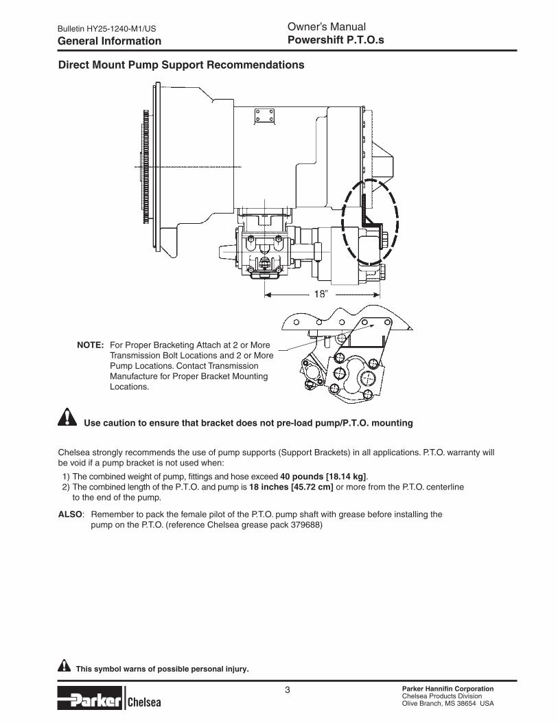
Direct Mount Pump Support Recommendations
Chelsea strongly recommends the use of pump supports (Support Brackets) in all applications. P.T.O. warranty will be void if a pump bracket is not used when:
1) The combined weight of pump, fittings and hose exceed 40 pounds [18.14 kg]. 2) The combined length of the P.T.O. and pump is 18 inches [45.72 cm] or more from the P.T.O. centerline to the end of the pump.
ALSO: Remember to pack the female pilot of the P.T.O. pump shaft with grease before installing the pump on the P.T.O. (reference Chelsea grease pack 379688)
Use caution to ensure that bracket does not pre-load pump/P.T.O. mounting
NOTe: For Proper Bracketing Attach at 2 or More Transmission Bolt Locations and 2 or More Pump Locations. Contact Transmission Manufacture for Proper Bracket Mounting Locations.
This symbol warns of possible personal injury.
3
"

Bulletin HY25-1240-M1/US Owner’s ManualPowershift P.T.O.s
Parker Hannifin CorporationChelsea Products DivisionOlive Branch, MS 38654 USA
Parker Hannifin CorporationChelsea Products DivisionOlive Branch, MS 38654 USA
Parker Hannifin CorporationChelsea Products DivisionOlive Branch, MS 38654 USA
Parker Hannifin CorporationChelsea Products DivisionOlive Branch, MS 38654 USA
General Information
This booklet will provide you with information on correct installation of Chelsea® Power Take-Offs (P.T.O.’s). Proper installation and set up procedures will help you get additional and more profitable miles from your truck equipment and components.
It is important that you be sure that you are getting the right transmission/P.T.O. combination when you order a new truck. An inadequate transmission will overwork any P.T.O. in a short period of time. In addition, a mis-matched transmission and P.T.O. combination can result in unsatisfactory performance of your auxiliary power system from the start.
If you have questions regarding correct P.T.O. and transmission combination, please contact your local Chelsea® Auxiliary Power Specialist. They can help you select the properly matched components to insure correct and efficient applications.
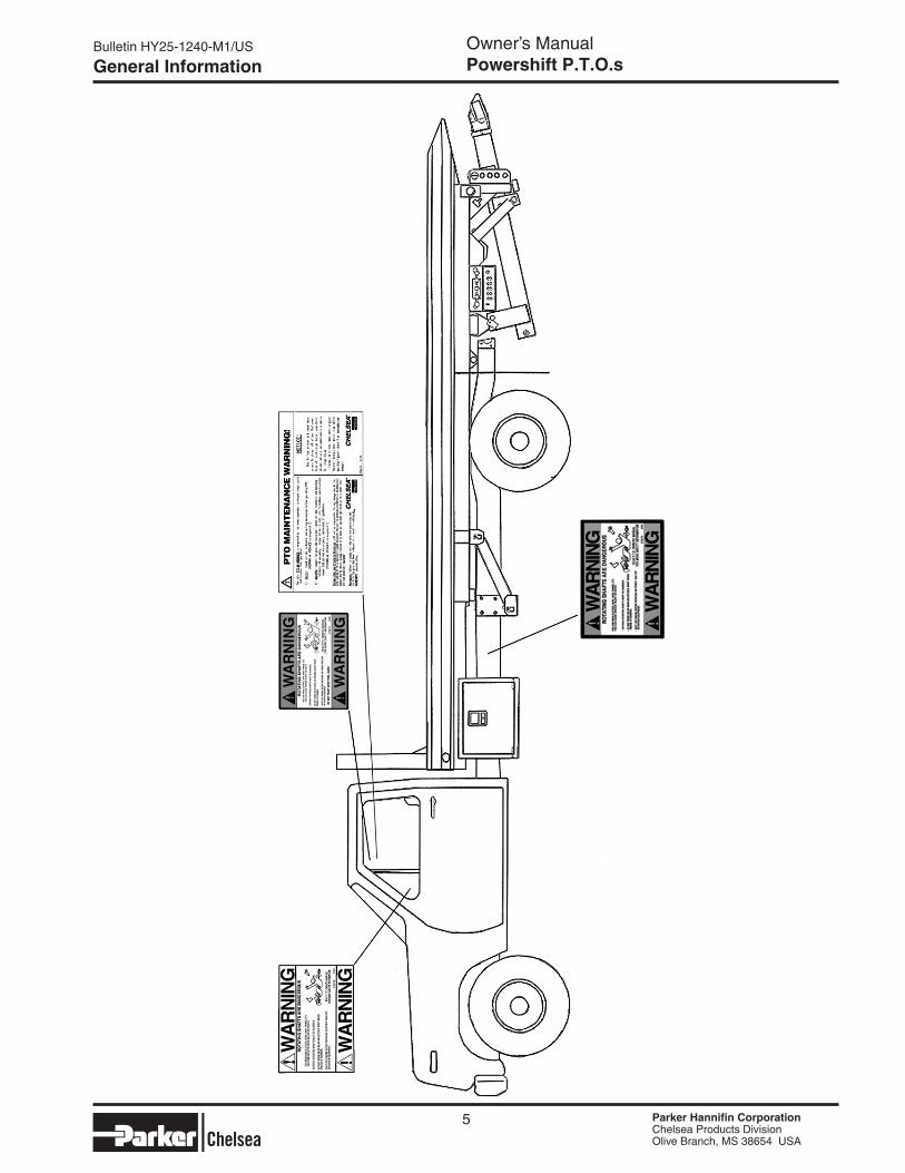
Chelsea P.T.O. Safety Label Instructions
1. The two black and orange on white 5" x 7" pressure sensitive vinyl labels, part number 379274; must be placed on the vehicle frame rails (one (1) on each side), in a position that would be HIGHLY visible to any-one that would go under the truck near the P.T.O. rotating shaft. If the vehicle is to be painted after these labels are installed, cover them with two (2) blank masking covers. Remove the masking covers after painting.
2. Place the one (1) black and orange on white 3.5" x 5" pressure sensitive vinyl label, part number 379275, on the visor nearest the operator of the vehicle, this must be placed near the P.T.O. visor label.
3. Place the one (1) red and white with black lettering 3.5" x 7.5" pressure sensitive vinyl label, part number 379915, on the opposite side of the visor from the above label #379275.
4. Place the one (1) white and black heavy duty card, part number 379276, in the vehicle glove box. Again in a position highly visible to the operator, for example: try to place this card on top of whatever may be in the glove box.
If you require labels, please order part number 328946X at no charge from your local Chelsea Warehouse or send request direct to:
Foreword
4
Parker Hannifin CorporationChelsea Products Division8225 Hacks Cross RoadOlive Branch, MS 38654Customer Service: (662) 895-1011
Parker Hannifin CorporationChelsea Products DivisionOlive Branch, MS 38654 USA
Parker Hannifin CorporationChelsea Products DivisionOlive Branch, MS 38654 USA
Bulletin HY25-1240-M1/US Owner’s ManualPowershift P.T.O.s
Parker Hannifin CorporationChelsea Products DivisionOlive Branch, MS 38654 USA
Parker Hannifin CorporationChelsea Products DivisionOlive Branch, MS 38654 USA
General Information
5
Bulletin HY25-1240-M1/US Owner’s ManualPowershift P.T.O.s
Parker Hannifin CorporationChelsea Products DivisionOlive Branch, MS 38654 USA
Parker Hannifin CorporationChelsea Products DivisionOlive Branch, MS 38654 USA
Parker Hannifin CorporationChelsea Products DivisionOlive Branch, MS 38654 USA
Parker Hannifin CorporationChelsea Products DivisionOlive Branch, MS 38654 USA
General Information
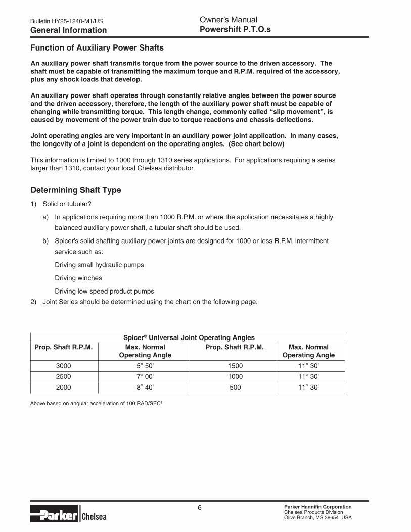
Spicer® Universal Joint Operating Angles Prop. Shaft R.P.M. Max. Normal Prop. Shaft R.P.M. Max. Normal Operating Angle Operating Angle
3000 5° 50' 1500 11° 30'
2500 7° 00' 1000 11° 30'
2000 8° 40' 500 11° 30'
Above based on angular acceleration of 100 RAD/SEC2
Function of Auxiliary Power Shafts
An auxiliary power shaft transmits torque from the power source to the driven accessory. The shaft must be capable of transmitting the maximum torque and R.P.M. required of the accessory, plus any shock loads that develop.
An auxiliary power shaft operates through constantly relative angles between the power source and the driven accessory, therefore, the length of the auxiliary power shaft must be capable of changing while transmitting torque. This length change, commonly called “slip movement”, is caused by movement of the power train due to torque reactions and chassis deflections.
Joint operating angles are very important in an auxiliary power joint application. In many cases, the longevity of a joint is dependent on the operating angles. (See chart below)
This information is limited to 1000 through 1310 series applications. For applications requiring a series larger than 1310, contact your local Chelsea distributor.
Determining Shaft Type
1) Solid or tubular?
a) In applications requiring more than 1000 R.P.M. or where the application necessitates a highly
balanced auxiliary power shaft, a tubular shaft should be used.
b) Spicer’s solid shafting auxiliary power joints are designed for 1000 or less R.P.M. intermittent
service such as:
Driving small hydraulic pumps
Driving winches
Driving low speed product pumps
2) Joint Series should be determined using the chart on the following page.
6
Parker Hannifin CorporationChelsea Products DivisionOlive Branch, MS 38654 USA
Parker Hannifin CorporationChelsea Products DivisionOlive Branch, MS 38654 USA
Bulletin HY25-1240-M1/US Owner’s ManualPowershift P.T.O.s
Parker Hannifin CorporationChelsea Products DivisionOlive Branch, MS 38654 USA
Parker Hannifin CorporationChelsea Products DivisionOlive Branch, MS 38654 USA
General Information
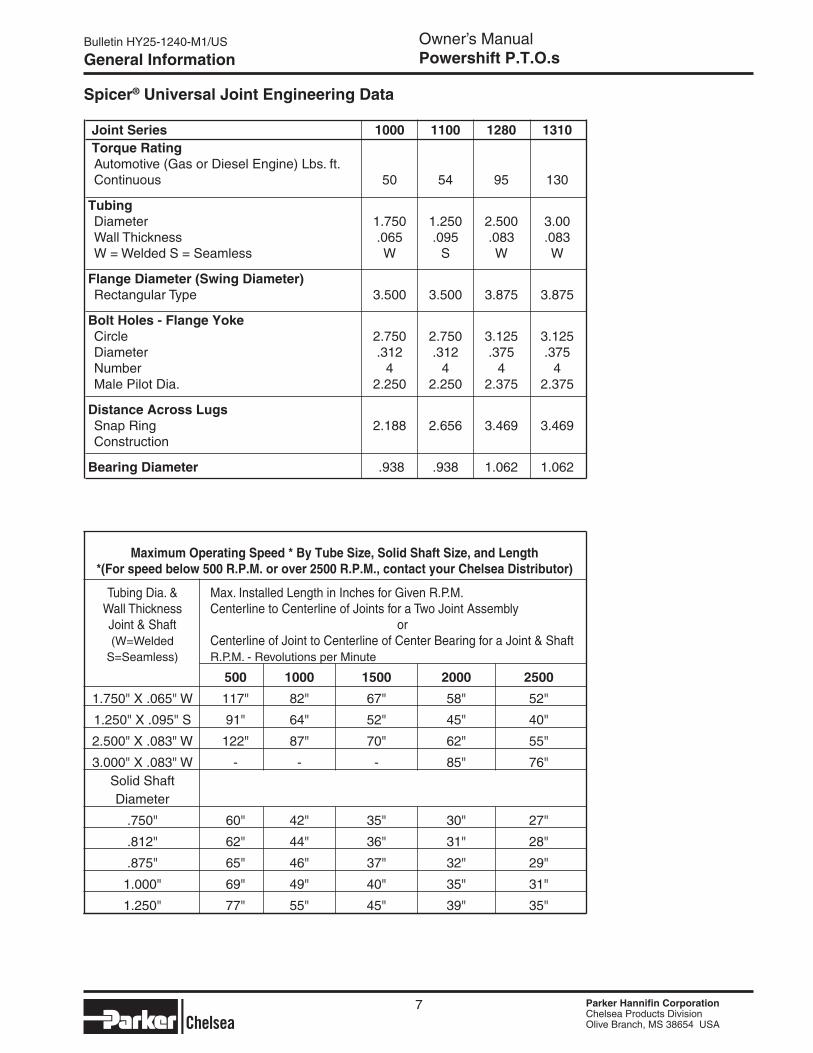
Spicer® Universal Joint engineering Data
Joint Series 1000 1100 1280 1310 Torque Rating Automotive (Gas or Diesel Engine) Lbs. ft. Continuous 50 54 95 130
Tubing Diameter 1.750 1.250 2.500 3.00 Wall Thickness .065 .095 .083 .083 W = Welded S = Seamless W S W W
Flange Diameter (Swing Diameter) Rectangular Type 3.500 3.500 3.875 3.875
Bolt Holes - Flange Yoke Circle 2.750 2.750 3.125 3.125 Diameter .312 .312 .375 .375 Number 4 4 4 4 Male Pilot Dia. 2.250 2.250 2.375 2.375
Distance Across Lugs Snap Ring 2.188 2.656 3.469 3.469 Construction
Bearing Diameter .938 .938 1.062 1.062
Maximum Operating Speed * By Tube Size, Solid Shaft Size, and Length*(For speed below 500 R.P.M. or over 2500 R.P.M., contact your Chelsea Distributor)
Tubing Dia. & Max. Installed Length in Inches for Given R.P.M. Wall Thickness Centerline to Centerline of Joints for a Two Joint Assembly Joint & Shaft or (W=Welded Centerline of Joint to Centerline of Center Bearing for a Joint & Shaft S=Seamless) R.P.M. - Revolutions per Minute
500 1000 1500 2000 2500
1.750" X .065" W 117" 82" 67" 58" 52"
1.250" X .095" S 91" 64" 52" 45" 40"
2.500" X .083" W 122" 87" 70" 62" 55"
3.000" X .083" W - - - 85" 76" Solid Shaft Diameter
.750" 60" 42" 35" 30" 27"
.812" 62" 44" 36" 31" 28"
.875" 65" 46" 37" 32" 29"
1.000" 69" 49" 40" 35" 31"
1.250" 77" 55" 45" 39" 35"
7
Bulletin HY25-1240-M1/US Owner’s ManualPowershift P.T.O.s
Parker Hannifin CorporationChelsea Products DivisionOlive Branch, MS 38654 USA
Parker Hannifin CorporationChelsea Products DivisionOlive Branch, MS 38654 USA
Parker Hannifin CorporationChelsea Products DivisionOlive Branch, MS 38654 USA
Parker Hannifin CorporationChelsea Products DivisionOlive Branch, MS 38654 USA
General Information
8
Dodge/Sterling Overview
P.T.O. Operation
The 3500/4500/5500 Dodge Chassis Cab vehicle, when equipped with either the automatic Aisin 6 speed or manual G-56 6 speed transmissions, will allow for an aftermarket upfit with a transmission driven P.T.O. (Power Take-Off). The customer will have the ability to operate the P.T.O. in either a “stationary” or “mobile” mode. The vehicles will be factory set to the “stationary” mode. In order to select the “mobile” mode a DaimlerChrysler Dealership is required to modify the vehicles settings using their proprietary Dealer service tool.
Stationary Mode
To operate the P.T.O. in this mode the vehicle must meet the following conditions: •Bein“park”positions(vehiclesequippedwithautomatictransmission) •Upfitterprovider(on/off)switchhasbeenactivated •Parkingbrakeapplied(vehiclesequippedwithmanualtransmission) •Vehiclemustberunning •Novehicle,brakeorclutchswitchfaultspresent •P.T.O.mustbecorrectlyinstalledusingthevehicleprovidedcircuits
The customer has the choice to operate the P.T.O. by utilizing the cruise control switches or by utilizing a remote control (provided by the P.T.O. supplier). To operate the feature using the cruise control switches the customer must first activate the up fitter provided on/off switch. Next, the cruise control “on” switch is selected. Following this step the “set” switch must be depressed. The vehicle is now in the P.T.O. mode and is ready for use. In order to increase or decrease the engine idle speed, to optimize the P.T.O. function, the “accel” and “decel” cruise switches can be used respectively. To disengage P.T.O. operation and return to “standard vehicle operation” simply turn the up fitter provided on/off switch to the off position.
To operate the P.T.O. via a remote switch the customer must make sure the above conditions are met. It is vital for proper operation that the P.T.O. and remote have been installed correctly paying special attention to ensure the vehicle provided wiring has been connected properly. This is the responsibility of the installer of the P.T.O. and switches/remote system. It is the responsibility of the P.T.O. manufacturer to ensure that their electrical (switches and remote) system is compatible with the vehicle's electrical architecture and software functionality.
Mobile Mode
To operate the P.T.O. in this mode the vehicle must meet the following conditions: •Dealerselected“mobile”modeactivatedviaDealerproprietaryservicetool •Upfitterprovider(on/off)switchhasbeenactivated •Vehiclemustbein“park”or“drive”position(vehiclesequippedwithautomatictransmission) •Parkingbrakemustnotbeapplied •Novehicle,brakeorclutchswitchfaultspresent •Vehiclemustberunning •P.T.O.mustbecorrectlyinstalledusingthevehicleprovidedcircuits
The customer may choose to use the P.T.O. while the vehicle is moving. To do so the P.T.O. function must be activated prior to taking the vehicle out of “park”. This is accomplished by activating the up fitter provided P.T.O. on/off switch. At this point the customer may place the vehicle in a forward or reverse gear and have P.T.O. operation. To disengage P.T.O. operation and return to “standard vehicle operation” simply turn the up fitter provided on/off switch to the off position.
NOTe: For application specific information with respect to P.T.O. and pump requirements and additional ve-hicle information (wiring schematics, preset idle values, engine speed limits, and vehicle hardware and software requirements) please refer to the Dodge Body Builders Guide by accessing “Wiring Diagrams” and choosing the appropriate links.

Parker Hannifin CorporationChelsea Products DivisionOlive Branch, MS 38654 USA
Parker Hannifin CorporationChelsea Products DivisionOlive Branch, MS 38654 USA
Bulletin HY25-1240-M1/US Owner’s ManualPowershift P.T.O.s
Parker Hannifin CorporationChelsea Products DivisionOlive Branch, MS 38654 USA
Parker Hannifin CorporationChelsea Products DivisionOlive Branch, MS 38654 USA
Installation Overview
With the introduction of the 6.7-liter Turbo Diesel engine with the new Aisin 6 - speed automatic transmission in the Dodge/Sterling 2007 Work Trucks there are several important installation steps that are unique to the Dodge/Sterling/Aisin combination.
1. Prior to installing the P.T.O. to the transmission verify that on the passenger side floor pan there is a modified “bulge” installed. (Fig. 1)
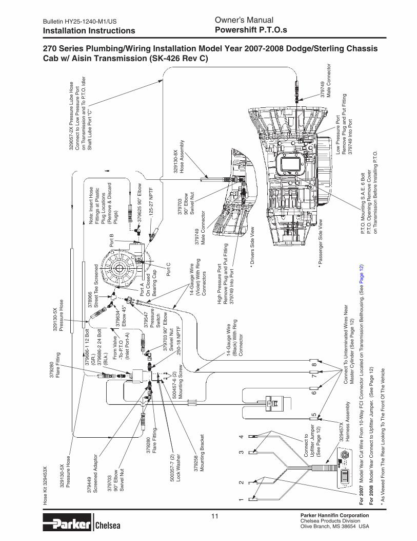
2. Before installing the P.T.O. to the transmission pre-install the hoses to the P.T.O. (Refer to Installation Drawings SK-426 for hose connections on Page 11.)
3. To access the P.T.O. aperture on the right (passenger) side of the transmission, the exhaust pipe will need to be removed. (Fig. 2)
Figure 1
Figure 24. To make this process easier the following information is provided. The front end of the exhaust pipe at the turbocharger is secured with a V band clamp part number 52121895AB. It is tightened to a torque value of 150 inch pounds. At the rear of the pipe the M10x1.5 nuts are torqued to 43 Lbs. ft.
The part number for the gasket that is located between the front pipe and the catalytic converter/particulate filter (if it is damaged or lost) is 52122213AB.
More specific instructions on removing and installing the exhaust pipe are available in the Dodge Truck service manual.
If there are any additional questions related to this procedure please contact the Dodge Truck Body Builder Hotline at (866) 205-4102 or [email protected].
5. Install Power Take-Off as described on pages 13-17 of this manual.
Installation Instructions
9
2007-2008 Dodge/Sterling Heavy Duty Chassis Cab P.T.O.

Bulletin HY25-1240-M1/US Owner’s ManualPowershift P.T.O.s
Parker Hannifin CorporationChelsea Products DivisionOlive Branch, MS 38654 USA
Parker Hannifin CorporationChelsea Products DivisionOlive Branch, MS 38654 USA
Parker Hannifin CorporationChelsea Products DivisionOlive Branch, MS 38654 USA
Parker Hannifin CorporationChelsea Products DivisionOlive Branch, MS 38654 USA
6. Before mounting the P.T.O. remove the high pressure port plug located on the left side (drivers side of transmission) and install part number 379749 male connector fitting into port. Also install the 90° swivel nut (part number 379703) onto the male connector (379749) (Fig. 3).
NOTe: Refer to “Installation Sketches SK-426 for complete wiring and plumbing instructions starting on page 11 of this owner’s manual.
7. Next remove the low pressure port plug located on the right side (passenger side of transmission) and install part number 379479 male connector fitting into port. (Fig. 4)
8. One recommendation for installation of the P.T.O. Remote Solenoid Valve is to locate it at the bottom forward area of the transmission housing. (Fig. 5)
9. Refer to “Installation Instructions” pages 13-14 of the owner’s manual for proper 270 Series P.T.O. mounting.
10. After P.T.O. has been mounted connect hoses as shown on SK-426.
Figure 5
Bulletin HY25-1240-M1/US
Installation Instructions
10
Figure 3
Figure 4
379749 Male Connector
329130-8X Hose Assembly
High Pressure Port Remove Plug and Put Fitting 379749 Into Port
Low Pressure Port Remove Plug and Put Fitting 379749 Into Port
379749 Male Connector
379703 90° Elbow Swivel Nut
Parker Hannifin CorporationChelsea Products DivisionOlive Branch, MS 38654 USA
Parker Hannifin CorporationChelsea Products DivisionOlive Branch, MS 38654 USA
Bulletin HY25-1240-M1/US Owner’s ManualPowershift P.T.O.s
Parker Hannifin CorporationChelsea Products DivisionOlive Branch, MS 38654 USA
Parker Hannifin CorporationChelsea Products DivisionOlive Branch, MS 38654 USA
Installation Instructions
11
270 Series Plumbing/Wiring Installation Model Year 2007-2008 Dodge/Sterling Chassis Cab w/ Aisin Transmission (SK-426 Rev C)
12
34
58
76
3291
30-5
X
Pre
ssur
e H
ose
3794
49
Scr
eene
d A
dapt
or
3797
0390
° E
lbow
Sw
ivel
Nut
3792
80F
lare
Fitt
ing
3796
86-1
12
Bol
t (G
R.)
3796
86-2
24
Bol
t (B
Lk.)
3792
80F
lare
Fitt
ing
3797
03 9
0° E
lbow
Sw
ivel
Nut
3291
30-5
XP
ress
ure
Hos
e
.250
-18
NP
TF
5003
57-7
(2)
Lock
Was
her
5004
57-6
(2)
Mou
ntin
g S
crew
3792
58M
ount
ing
Bra
cket
3796
34E
lbow
45°
Por
t AO
n C
lose
d
Bea
ring
Cap
3795
47P
ress
ure
Sw
itch
From
Val
ve
-To-
P.T.
O
(Inl
et P
ort-
A)
14-G
auge
Wire
(B
lack
) With
Rin
g C
onne
ctor
3789
66
Str
eet T
ee S
cree
ned
Por
t C
14-G
auge
Wire
(V
iole
t) W
ith R
ing
Con
nect
ors
Por
t B
.125
-27
NP
TF
3797
49M
ale
Con
nect
or3797
0390
° E
lbow
Sw
ivel
Nut
3290
57-2
X P
ress
ure
Lube
Hos
eC
onne
ct to
Low
Pre
ssur
e P
ort
on T
rans
mis
sion
and
To
P.T.
O. I
dler
S
haft
Lube
Por
t “C
”
Hig
h P
ress
ure
Por
tR
emov
e P
lug
and
Put
Fitt
ing
3797
49 In
to P
ort
3797
49M
ale
Con
nect
or
Low
Pre
ssur
e P
ort
Rem
ove
Plu
g an
d P
ut F
ittin
g 37
9749
Into
Por
t
3291
30-8
XH
ose
Ass
embl
y
P.T.
O. M
ount
ing
S.A
.E. 6
Bol
tP.
T.O
. Ope
ning
Rem
ove
Cov
er
on T
rans
mis
sion
Bef
ore
Inst
allin
g P.
T.O
.
Con
nect
To
Unt
erm
inat
ed W
ires
Nea
r M
aste
r C
ylin
der
(See
Pag
e 12
)
3294
57X
Har
ness
Ass
embl
y
Not
e: In
sert
Hos
e F
ittin
gs a
t Pla
stic
P
lug
Loca
tions
(R
emov
e &
Dis
card
P
lugs
)
Fo
r 20
07 M
odel
Yea
r C
ut W
ire F
rom
10-
Way
FC
I Con
nect
or L
ocat
ed o
n Tr
ansm
issi
on B
ellh
ousi
ng. (
See
Pag
e 12
)
Con
nect
to
Upfi
tter
Jum
per
(See
Pag
e 12
)
3796
25 9
0° E
lbow
Hos
e K
it 32
9453
X
* A
s V
iew
ed F
rom
The
Rea
r Lo
okin
g To
The
Fro
nt O
f The
Veh
icle
* D
river
s S
ide
Vie
w
* P
asse
nger
Sid
e V
iew
Fo
r 20
08 M
odel
Yea
r C
onne
ct to
Upfi
tter
Jum
per.
(S
ee P
age
12)
Bulletin HY25-1240-M1/US Owner’s ManualPowershift P.T.O.s
Parker Hannifin CorporationChelsea Products DivisionOlive Branch, MS 38654 USA
Parker Hannifin CorporationChelsea Products DivisionOlive Branch, MS 38654 USA
Parker Hannifin CorporationChelsea Products DivisionOlive Branch, MS 38654 USA
Parker Hannifin CorporationChelsea Products DivisionOlive Branch, MS 38654 USA
Installation Instructions
12
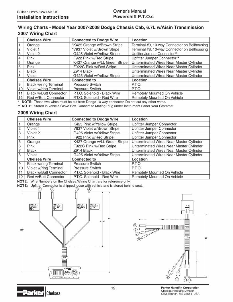
* NOTe: These two wires must be cut from Dodge 10 way connector. Do not cut any other wires.** NOTe: Stored in Vehicle Glove Box. Connect to Mating Plug under Instrument Panel Near Grommet.
Wiring Charts - Model Year 2007-2008 Dodge Chassis Cab, 6.7L w/Aisin Transmission
2008 Wiring Chart
2007 Wiring Chart Chelsea Wire Connected to Dodge Wire Location1 Orange * K425 Orange w/Brown Stripe Terminal #9, 10-way Connector on Bellhousing2 Violet 1 * V937 Violet w/Brown Stripe Terminal #8, 10-way Connector on Bellhousing3 Violet 2 G425 Violet w/Yellow Stripe Upfitter Jumper Connector**4 Pink F922 Pink w/Red Stripe Upfitter Jumper Connector**5 Orange K427 Orange w/Lt. Green Stripe Unterminated Wires Near Master Cylinder6 Pink F922C Pink w/Red Stripe Unterminated Wires Near Master Cylinder7 Black Z914 Black Unterminated Wires Near Master Cylinder8 Violet G425 Violet w/Yellow Stripe Unterminated Wires Near Master Cylinder Chelsea Wire Connected to Location9 Black w/ring Terminal Pressure Switch P.T.O.10 Violet w/ring Terminal Pressure Switch P.T.O.11 Black w/Butt Connector P.T.O. Solenoid - Black Wire Remotely Mounted On Vehicle12 Red w/Butt Connector P.T.O. Solenoid - Red Wire Remotely Mounted On Vehicle
Chelsea Wire Connected to Dodge Wire Location1 Orange K425 Pink w/Yellow Stripe Upfitter Jumper Connector2 Violet 1 V937 Violet w/Brown Stripe Upfitter Jumper Connector3 Violet 2 G425 Violet w/Yellow Stripe Upfitter Jumper Connector4 Pink F922 Pink w/Red Stripe Upfitter Jumper Connector5 Orange K427 Orange w/Lt. Green Stripe Unterminated Wires Near Master Cylinder6 Pink F922C Pink w/Red Stripe Unterminated Wires Near Master Cylinder7 Black Z914 Black Unterminated Wires Near Master Cylinder8 Violet G425 Violet w/Yellow Stripe Unterminated Wires Near Master Cylinder Chelsea Wire Connected to Location9 Black w/ring Terminal Pressure Switch P.T.O.10 Violet w/ring Terminal Pressure Switch P.T.O.11 Black w/Butt Connector P.T.O. Solenoid - Black Wire Remotely Mounted On Vehicle12 Red w/Butt Connector P.T.O. Solenoid - Red Wire Remotely Mounted On Vehicle
1 432
5
11 12109
8
76
NOTe: Wire Numbers on the Chelsea Wiring Chart are for reference only.NOTe: Upfitter Connector is shipped loose with vehicle and is stored behind seat.
Parker Hannifin CorporationChelsea Products DivisionOlive Branch, MS 38654 USA
Parker Hannifin CorporationChelsea Products DivisionOlive Branch, MS 38654 USA
Bulletin HY25-1240-M1/US Owner’s ManualPowershift P.T.O.s
Parker Hannifin CorporationChelsea Products DivisionOlive Branch, MS 38654 USA
Parker Hannifin CorporationChelsea Products DivisionOlive Branch, MS 38654 USA
Installation Instructions
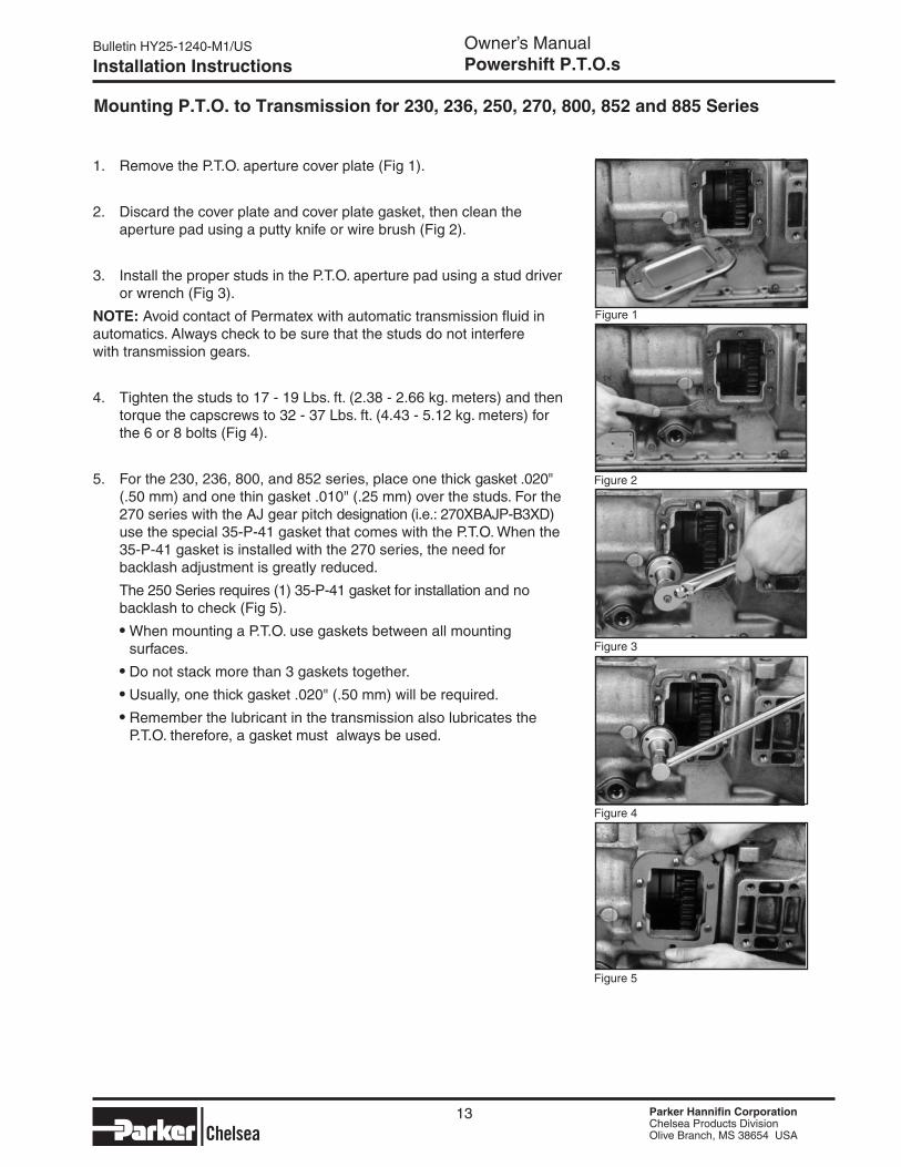
1. Remove the P.T.O. aperture cover plate (Fig 1).
2. Discard the cover plate and cover plate gasket, then clean the aperture pad using a putty knife or wire brush (Fig 2).
3. Install the proper studs in the P.T.O. aperture pad using a stud driver or wrench (Fig 3).
NOTe: Avoid contact of Permatex with automatic transmission fluid in automatics. Always check to be sure that the studs do not interfere with transmission gears.
4. Tighten the studs to 17 - 19 Lbs. ft. (2.38 - 2.66 kg. meters) and then torque the capscrews to 32 - 37 Lbs. ft. (4.43 - 5.12 kg. meters) for the 6 or 8 bolts (Fig 4).
5. For the 230, 236, 800, and 852 series, place one thick gasket .020" (.50 mm) and one thin gasket .010" (.25 mm) over the studs. For the 270 series with the AJ gear pitch designation (i.e.: 270XBAJP-B3XD) use the special 35-P-41 gasket that comes with the P.T.O. When the 35-P-41 gasket is installed with the 270 series, the need for backlash adjustment is greatly reduced.
The 250 Series requires (1) 35-P-41 gasket for installation and no backlash to check (Fig 5). ● When mounting a P.T.O. use gaskets between all mounting surfaces. ● Do not stack more than 3 gaskets together. ● Usually, one thick gasket .020" (.50 mm) will be required. ● Remember the lubricant in the transmission also lubricates the P.T.O. therefore, a gasket must always be used.
Mounting P.T.O. to Transmission for 230, 236, 250, 270, 800, 852 and 885 Series
Figure 4
13
Figure 5
Figure 2
Figure 3
Figure 1
Bulletin HY25-1240-M1/US Owner’s ManualPowershift P.T.O.s
Parker Hannifin CorporationChelsea Products DivisionOlive Branch, MS 38654 USA
Parker Hannifin CorporationChelsea Products DivisionOlive Branch, MS 38654 USA
Parker Hannifin CorporationChelsea Products DivisionOlive Branch, MS 38654 USA
Parker Hannifin CorporationChelsea Products DivisionOlive Branch, MS 38654 USA
Installation Instructions
Figure 7
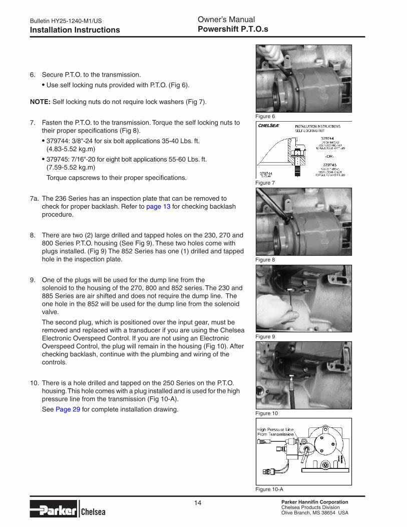
6. Secure P.T.O. to the transmission. ● Use self locking nuts provided with P.T.O. (Fig 6).
NOTe: Self locking nuts do not require lock washers (Fig 7).
7. Fasten the P.T.O. to the transmission. Torque the self locking nuts to their proper specifications (Fig 8). ● 379744: 3/8"-24 for six bolt applications 35-40 Lbs. ft. (4.83-5.52 kg.m) ● 379745: 7/16"-20 for eight bolt applications 55-60 Lbs. ft. (7.59-5.52 kg.m)
Torque capscrews to their proper specifications.
7a. The 236 Series has an inspection plate that can be removed to check for proper backlash. Refer to page 13 for checking backlash procedure.
8. There are two (2) large drilled and tapped holes on the 230, 270 and 800 Series P.T.O. housing (See Fig 9). These two holes come with plugs installed. (Fig 9) The 852 Series has one (1) drilled and tapped hole in the inspection plate.
9. One of the plugs will be used for the dump line from the solenoid to the housing of the 270, 800 and 852 series. The 230 and 885 Series are air shifted and does not require the dump line. The one hole in the 852 will be used for the dump line from the solenoid valve.
The second plug, which is positioned over the input gear, must be removed and replaced with a transducer if you are using the Chelsea Electronic Overspeed Control. If you are not using an Electronic Overspeed Control, the plug will remain in the housing (Fig 10). After checking backlash, continue with the plumbing and wiring of the controls.
10. There is a hole drilled and tapped on the 250 Series on the P.T.O. housing. This hole comes with a plug installed and is used for the high pressure line from the transmission (Fig 10-A).
See Page 29 for complete installation drawing.
Figure 9
Figure 8
Figure 10
Figure 10-A
14
Figure 6
Parker Hannifin CorporationChelsea Products DivisionOlive Branch, MS 38654 USA
Parker Hannifin CorporationChelsea Products DivisionOlive Branch, MS 38654 USA
Bulletin HY25-1240-M1/US Owner’s ManualPowershift P.T.O.s
Parker Hannifin CorporationChelsea Products DivisionOlive Branch, MS 38654 USA
Parker Hannifin CorporationChelsea Products DivisionOlive Branch, MS 38654 USA
Installation Instructions
Figure 5
Figure 4
Figure 2
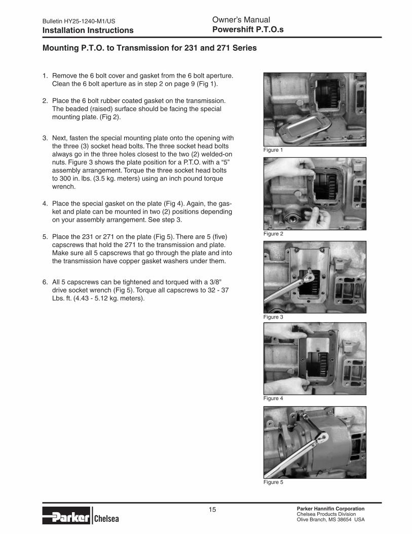
Mounting P.T.O. to Transmission for 231 and 271 Series
Figure 1
Figure 3
1. Remove the 6 bolt cover and gasket from the 6 bolt aperture. Clean the 6 bolt aperture as in step 2 on page 9 (Fig 1).
2. Place the 6 bolt rubber coated gasket on the transmission. The beaded (raised) surface should be facing the special mounting plate. (Fig 2).
3. Next, fasten the special mounting plate onto the opening with the three (3) socket head bolts. The three socket head bolts always go in the three holes closest to the two (2) welded-on nuts. Figure 3 shows the plate position for a P.T.O. with a “5” assembly arrangement. Torque the three socket head bolts to 300 in. lbs. (3.5 kg. meters) using an inch pound torque wrench.
4. Place the special gasket on the plate (Fig 4). Again, the gas-ket and plate can be mounted in two (2) positions depending on your assembly arrangement. See step 3.
5. Place the 231 or 271 on the plate (Fig 5). There are 5 (five) capscrews that hold the 271 to the transmission and plate. Make sure all 5 capscrews that go through the plate and into the transmission have copper gasket washers under them.
6. All 5 capscrews can be tightened and torqued with a 3/8" drive socket wrench (Fig 5). Torque all capscrews to 32 - 37 Lbs. ft. (4.43 - 5.12 kg. meters).
15
Bulletin HY25-1240-M1/US Owner’s ManualPowershift P.T.O.s
Parker Hannifin CorporationChelsea Products DivisionOlive Branch, MS 38654 USA
Parker Hannifin CorporationChelsea Products DivisionOlive Branch, MS 38654 USA
Parker Hannifin CorporationChelsea Products DivisionOlive Branch, MS 38654 USA
Parker Hannifin CorporationChelsea Products DivisionOlive Branch, MS 38654 USA
Installation Instructions
Figure 6
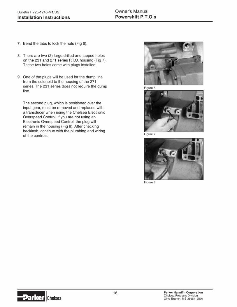
7. Bend the tabs to lock the nuts (Fig 6).
8. There are two (2) large drilled and tapped holes on the 231 and 271 series P.T.O. housing (Fig 7). These two holes come with plugs installed.
9. One of the plugs will be used for the dump line from the solenoid to the housing of the 271 series. The 231 series does not require the dump line.
The second plug, which is positioned over the input gear, must be removed and replaced with a transducer when using the Chelsea Electronic Overspeed Control. If you are not using an Electronic Overspeed Control, the plug will remain in the housing (Fig 8). After checking backlash, continue with the plumbing and wiring of the controls.
Figure 8
Figure 7
16
Parker Hannifin CorporationChelsea Products DivisionOlive Branch, MS 38654 USA
Parker Hannifin CorporationChelsea Products DivisionOlive Branch, MS 38654 USA
Bulletin HY25-1240-M1/US Owner’s ManualPowershift P.T.O.s
Parker Hannifin CorporationChelsea Products DivisionOlive Branch, MS 38654 USA
Parker Hannifin CorporationChelsea Products DivisionOlive Branch, MS 38654 USA
17
Bulletin HY25-1240-M1/US
Installation Instructions
Checking Backlash
Figure 10
Figure 9
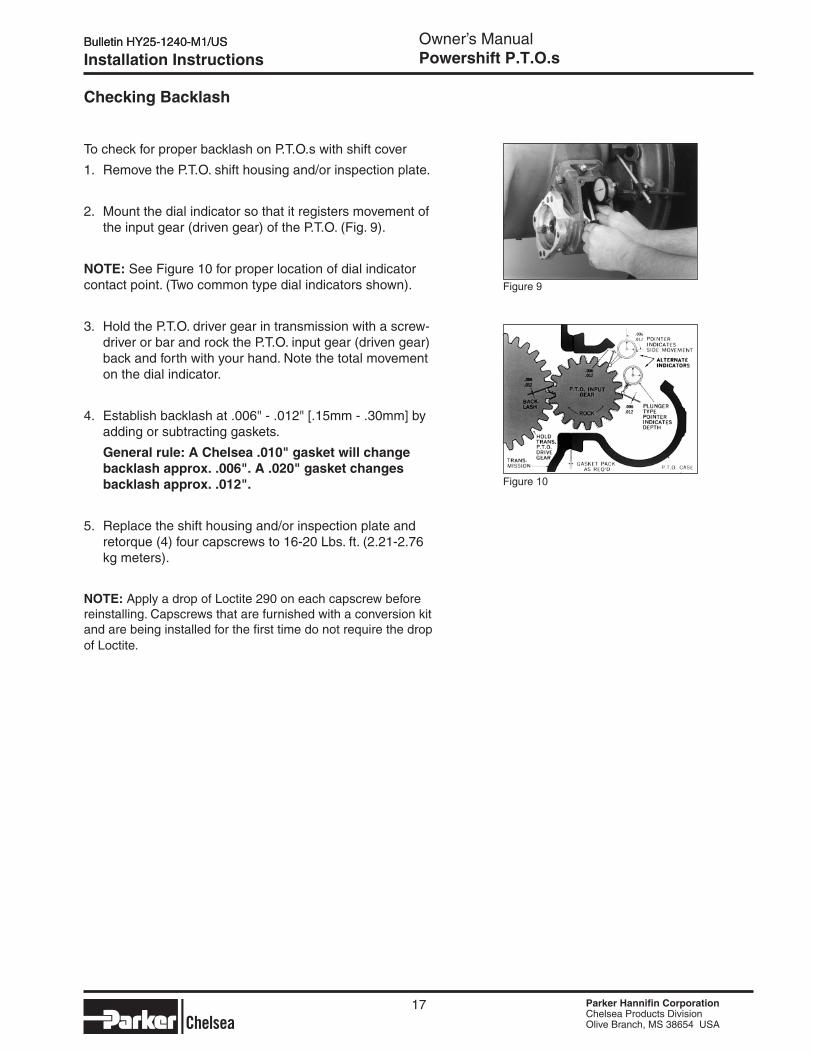
To check for proper backlash on P.T.O.s with shift cover
1. Remove the P.T.O. shift housing and/or inspection plate.
2. Mount the dial indicator so that it registers movement of the input gear (driven gear) of the P.T.O. (Fig. 9).
NOTe: See Figure 10 for proper location of dial indicator contact point. (Two common type dial indicators shown).
3. Hold the P.T.O. driver gear in transmission with a screw-driver or bar and rock the P.T.O. input gear (driven gear) back and forth with your hand. Note the total movement on the dial indicator.
4. Establish backlash at .006" - .012" [.15mm - .30mm] by adding or subtracting gaskets.
General rule: A Chelsea .010" gasket will change backlash approx. .006". A .020" gasket changes backlash approx. .012".
5. Replace the shift housing and/or inspection plate and retorque (4) four capscrews to 16-20 Lbs. ft. (2.21-2.76 kg meters).
NOTe: Apply a drop of Loctite 290 on each capscrew before reinstalling. Capscrews that are furnished with a conversion kit and are being installed for the first time do not require the drop of Loctite.
Bulletin HY25-1240-M1/US Owner’s ManualPowershift P.T.O.s
Parker Hannifin CorporationChelsea Products DivisionOlive Branch, MS 38654 USA
Parker Hannifin CorporationChelsea Products DivisionOlive Branch, MS 38654 USA
Parker Hannifin CorporationChelsea Products DivisionOlive Branch, MS 38654 USA
Parker Hannifin CorporationChelsea Products DivisionOlive Branch, MS 38654 USA
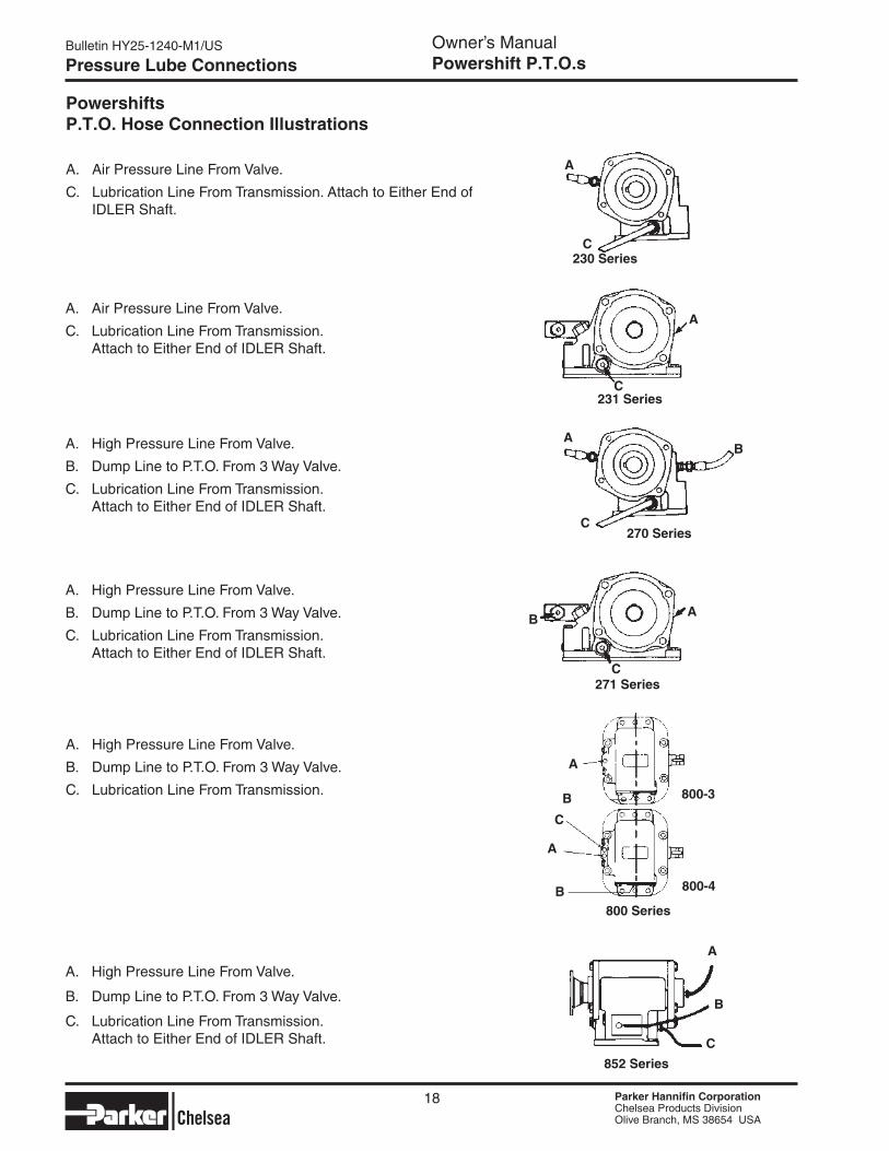
A. High Pressure Line From Valve.
B. Dump Line to P.T.O. From 3 Way Valve.
C. Lubrication Line From Transmission. Attach to Either End of IDLER Shaft.
Pressure Lube Connections
A. Air Pressure Line From Valve.
C. Lubrication Line From Transmission. Attach to Either End of IDLER Shaft.
A. Air Pressure Line From Valve.
C. Lubrication Line From Transmission. Attach to Either End of IDLER Shaft.
PowershiftsP.T.O. Hose Connection Illustrations
A. High Pressure Line From Valve.
B. Dump Line to P.T.O. From 3 Way Valve.
C. Lubrication Line From Transmission.
A. High Pressure Line From Valve.
B. Dump Line to P.T.O. From 3 Way Valve.
C. Lubrication Line From Transmission. Attach to Either End of IDLER Shaft.
A. High Pressure Line From Valve.
B. Dump Line to P.T.O. From 3 Way Valve.
C. Lubrication Line From Transmission. Attach to Either End of IDLER Shaft.
270 Series
A
C
B
231 Series
A
C
230 Series
A
C
271 SeriesC
AB
800 Series
A
B
C
A
B
800-3
800-4
852 Series
A
B
C
18
Parker Hannifin CorporationChelsea Products DivisionOlive Branch, MS 38654 USA
Parker Hannifin CorporationChelsea Products DivisionOlive Branch, MS 38654 USA
Bulletin HY25-1240-M1/US Owner’s ManualPowershift P.T.O.s
Parker Hannifin CorporationChelsea Products DivisionOlive Branch, MS 38654 USA
Parker Hannifin CorporationChelsea Products DivisionOlive Branch, MS 38654 USA
Pressure Lube Connections
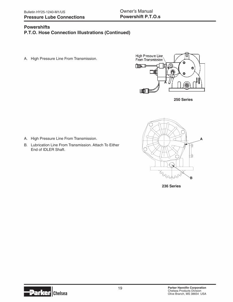
A. High Pressure Line From Transmission.
A
PowershiftsP.T.O. Hose Connection Illustrations (Continued)
19
250 Series
236 Series
A. High Pressure Line From Transmission.
B. Lubrication Line From Transmission. Attach To Either End of IDLER Shaft.
A
B
Bulletin HY25-1240-M1/US Owner’s ManualPowershift P.T.O.s
Parker Hannifin CorporationChelsea Products DivisionOlive Branch, MS 38654 USA
Parker Hannifin CorporationChelsea Products DivisionOlive Branch, MS 38654 USA
Parker Hannifin CorporationChelsea Products DivisionOlive Branch, MS 38654 USA
Parker Hannifin CorporationChelsea Products DivisionOlive Branch, MS 38654 USA
GM P.T.O. Connectors
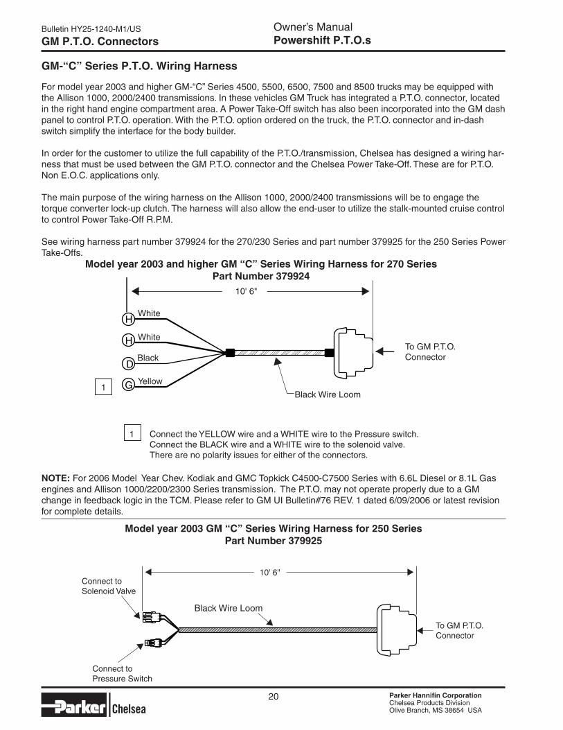
GM-“C” Series P.T.O. Wiring Harness
For model year 2003 and higher GM-“C” Series 4500, 5500, 6500, 7500 and 8500 trucks may be equipped with the Allison 1000, 2000/2400 transmissions. In these vehicles GM Truck has integrated a P.T.O. connector, located in the right hand engine compartment area. A Power Take-Off switch has also been incorporated into the GM dash panel to control P.T.O. operation. With the P.T.O. option ordered on the truck, the P.T.O. connector and in-dash switch simplify the interface for the body builder.
In order for the customer to utilize the full capability of the P.T.O./transmission, Chelsea has designed a wiring har-ness that must be used between the GM P.T.O. connector and the Chelsea Power Take-Off. These are for P.T.O. Non E.O.C. applications only.
The main purpose of the wiring harness on the Allison 1000, 2000/2400 transmissions will be to engage the torque converter lock-up clutch. The harness will also allow the end-user to utilize the stalk-mounted cruise control to control Power Take-Off R.P.M.
See wiring harness part number 379924 for the 270/230 Series and part number 379925 for the 250 Series Power Take-Offs.
2003 GM “C” Series Wiring Harness for 250 SeriesPart Number 379925
10' 6"
To GM P.T.O. Connector
Black Wire Loom
Connect to Solenoid Valve
Connect to Pressure Switch
20
Model year 2003 GM “C” Series Wiring Harness for 250 SeriesPart Number 379925
NOTe: For 2006 Model Year Chev. Kodiak and GMC Topkick C4500-C7500 Series with 6.6L Diesel or 8.1L Gas engines and Allison 1000/2200/2300 Series transmission. The P.T.O. may not operate properly due to a GM change in feedback logic in the TCM. Please refer to GM UI Bulletin#76 REV. 1 dated 6/09/2006 or latest revision for complete details.
Model year 2003 and higher GM “C” Series Wiring Harness for 270 SeriesPart Number 379924
Parker Hannifin CorporationChelsea Products DivisionOlive Branch, MS 38654 USA
Parker Hannifin CorporationChelsea Products DivisionOlive Branch, MS 38654 USA
Bulletin HY25-1240-M1/US Owner’s ManualPowershift P.T.O.s
Parker Hannifin CorporationChelsea Products DivisionOlive Branch, MS 38654 USA
Parker Hannifin CorporationChelsea Products DivisionOlive Branch, MS 38654 USA
To GM P.T.O. Connector
Connect to Solenoid Valve
Connect to Pressure Switch
Black Wire Loom
21
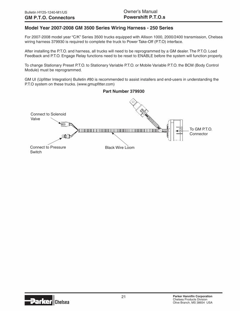
GM P.T.O. Connectors
For 2007-2008 model year “C/K” Series 3500 trucks equipped with Allison 1000, 2000/2400 transmission, Chelsea wiring harness 379930 is required to complete the truck to Power Take-Off (P.T.O) interface.
After installing the P.T.O. and harness, all trucks will need to be reprogrammed by a GM dealer. The P.T.O. Load Feedback and P.T.O. Engage Relay functions need to be reset to ENABLE before the system will function properly.
To change Stationary Preset P.T.O. to Stationary Variable P.T.O. or Mobile Variable P.T.O. the BCM (Body Control Module) must be reprogrammed.
GM UI (Upfitter Integration) Bulletin #80 is recommended to assist installers and end-users in understanding the P.T.O system on these trucks. (www.gmupfitter.com)
Model Year 2007-2008 GM 3500 Series Wiring Harness - 250 Series
Part Number 379930
Bulletin HY25-1240-M1/US Owner’s ManualPowershift P.T.O.s
Parker Hannifin CorporationChelsea Products DivisionOlive Branch, MS 38654 USA
Parker Hannifin CorporationChelsea Products DivisionOlive Branch, MS 38654 USA
Parker Hannifin CorporationChelsea Products DivisionOlive Branch, MS 38654 USA
Parker Hannifin CorporationChelsea Products DivisionOlive Branch, MS 38654 USA
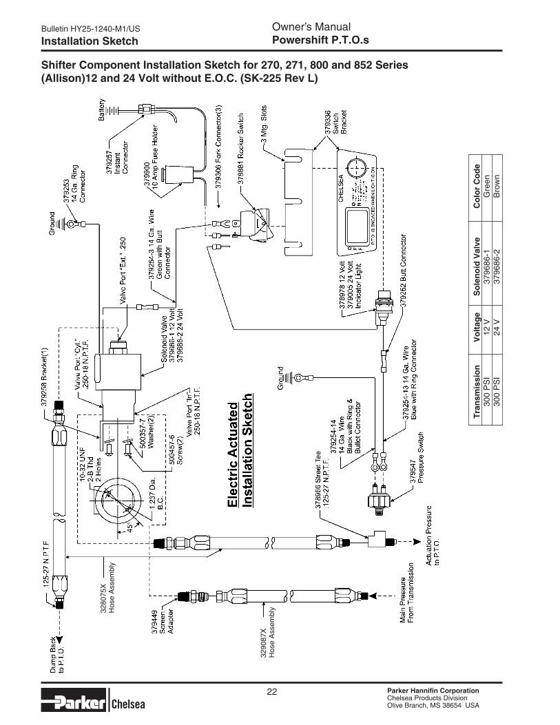
Installation Sketch
T
ran
smis
sio
n
Vo
ltag
e S
ole
no
id V
alve
C
olo
r C
od
e
300
PS
I 12
V
3796
86-1
G
reen
30
0 P
SI
24 V
37
9686
-2
Bro
wn
Shifter Component Installation Sketch for 270, 271, 800 and 852 Series (Allison)12 and 24 Volt without E.O.C. (SK-225 Rev L)
22
3280
75X
Hos
e A
ssem
bly
3290
87X
Hos
e A
ssem
bly
Parker Hannifin CorporationChelsea Products DivisionOlive Branch, MS 38654 USA
Parker Hannifin CorporationChelsea Products DivisionOlive Branch, MS 38654 USA
Bulletin HY25-1240-M1/US Owner’s ManualPowershift P.T.O.s
Parker Hannifin CorporationChelsea Products DivisionOlive Branch, MS 38654 USA
Parker Hannifin CorporationChelsea Products DivisionOlive Branch, MS 38654 USA
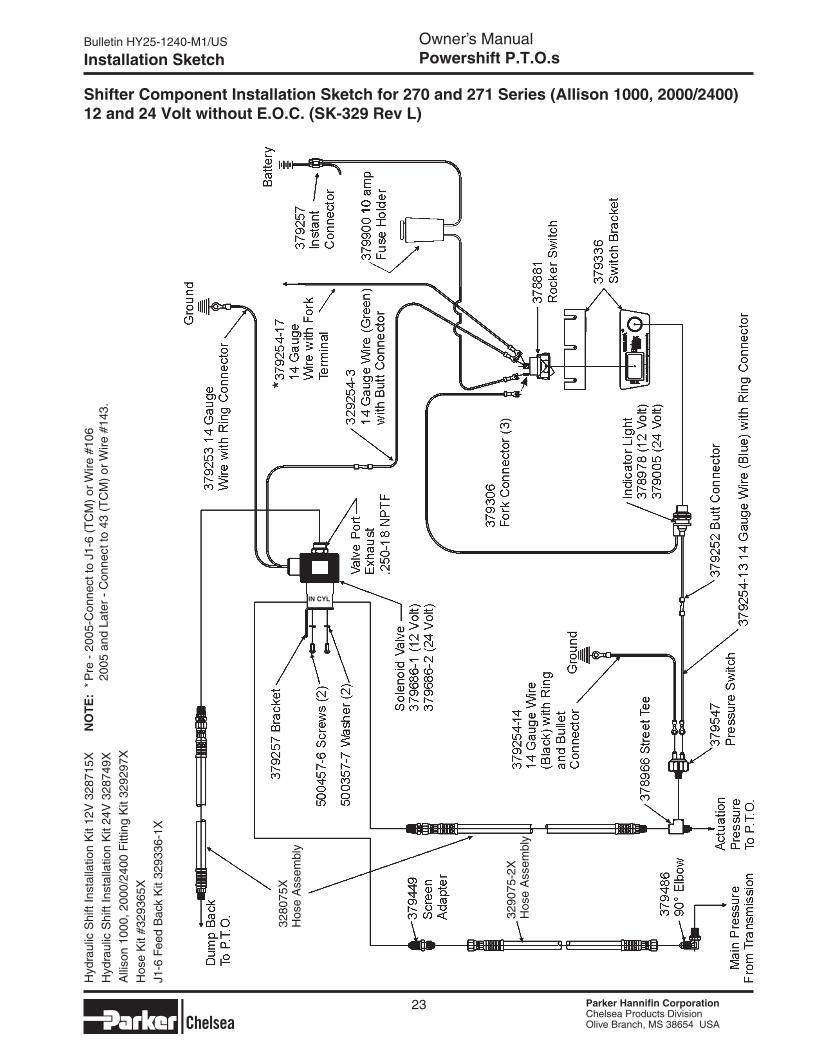
Installation Sketch
Shifter Component Installation Sketch for 270 and 271 Series (Allison 1000, 2000/2400) 12 and 24 Volt without E.O.C. (SK-329 Rev L)
23
Hyd
raul
ic S
hift
Inst
alla
tion
Kit
12V
328
715X
Hyd
raul
ic S
hift
Inst
alla
tion
Kit
24V
328
749X
Alli
son
1000
, 200
0/24
00 F
ittin
g K
it 32
9297
X
Hos
e K
it #3
2936
5X
J1-6
Fee
d B
ack
Kit
3293
36-1
X
3280
75X
Hos
e A
ssem
bly
3290
75-2
XH
ose
Ass
embl
y
IN CYL
NO
TE
: * P
re -
200
5-C
onne
ct to
J1-
6 (T
CM
) or
Wire
#10
6
200
5 an
d La
ter
- C
onne
ct to
43
(TC
M)
or W
ire #
143.
Bulletin HY25-1240-M1/US Owner’s ManualPowershift P.T.O.s
Parker Hannifin CorporationChelsea Products DivisionOlive Branch, MS 38654 USA
Parker Hannifin CorporationChelsea Products DivisionOlive Branch, MS 38654 USA
Parker Hannifin CorporationChelsea Products DivisionOlive Branch, MS 38654 USA
Parker Hannifin CorporationChelsea Products DivisionOlive Branch, MS 38654 USA
Installation Sketch
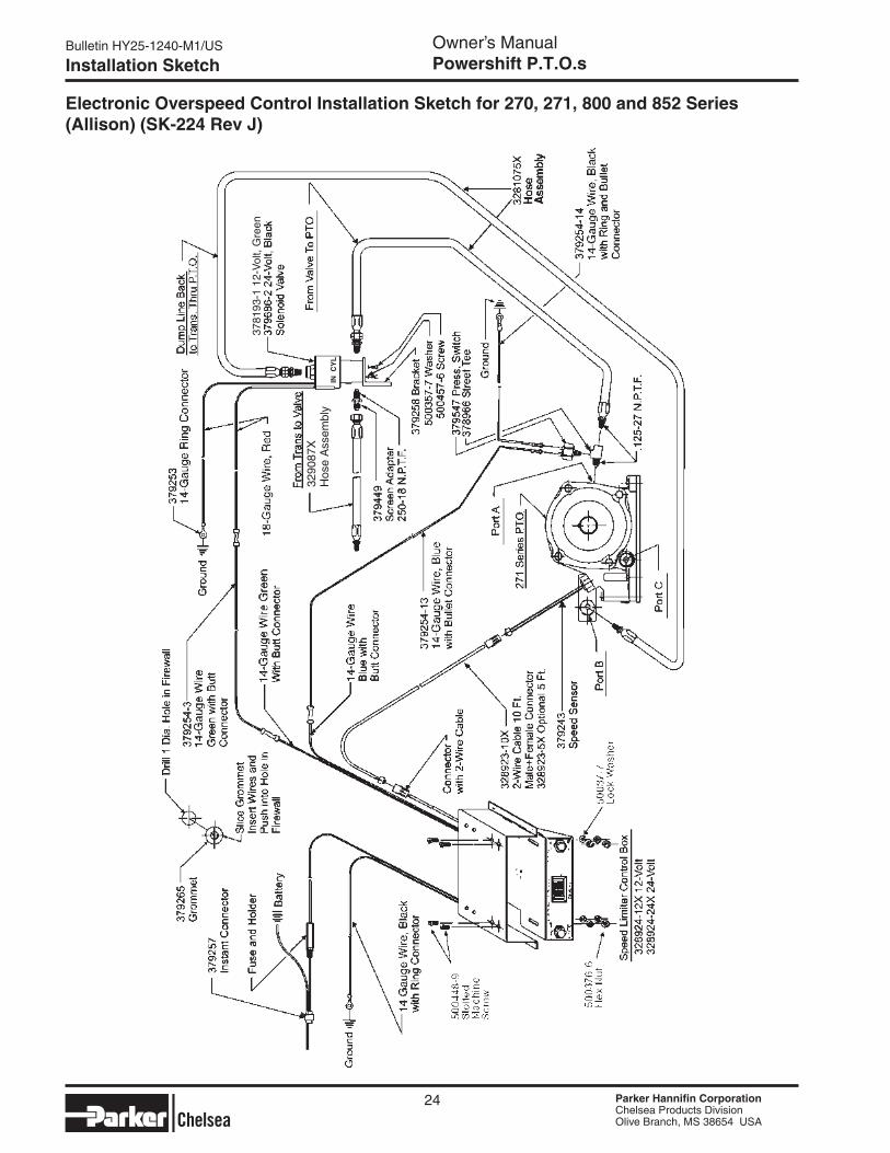
electronic Overspeed Control Installation Sketch for 270, 271, 800 and 852 Series (Allison) (SK-224 Rev J)
24
3290
87X
Hos
e A
ssem
bly
3781
93-1
12-
Vol
t, G
reen
IN C
YL
Parker Hannifin CorporationChelsea Products DivisionOlive Branch, MS 38654 USA
Parker Hannifin CorporationChelsea Products DivisionOlive Branch, MS 38654 USA
Bulletin HY25-1240-M1/US Owner’s ManualPowershift P.T.O.s
Parker Hannifin CorporationChelsea Products DivisionOlive Branch, MS 38654 USA
Parker Hannifin CorporationChelsea Products DivisionOlive Branch, MS 38654 USA
Installation Sketch
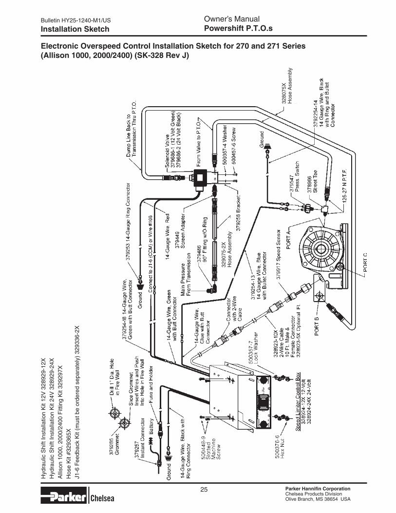
electronic Overspeed Control Installation Sketch for 270 and 271 Series (Allison 1000, 2000/2400) (SK-328 Rev J)
25
Hyd
raul
ic S
hift
Inst
alla
tion
Kit
12V
328
929-
12X
Hyd
raul
ic S
hift
Inst
alla
tion
Kit
24V
328
929-
24X
Alli
son
1000
, 200
0/24
00 F
ittin
g K
it 32
9297
X
Hos
e K
it #3
2936
5X
J1-6
Fee
dbac
k K
it (m
ust b
e or
dere
d se
para
tely
) 32
9336
-2X
3290
75-2
XH
ose
Ass
embl
y
IN
CY
L
3280
75X
Hos
e A
ssem
bly
Bulletin HY25-1240-M1/US Owner’s ManualPowershift P.T.O.s
Parker Hannifin CorporationChelsea Products DivisionOlive Branch, MS 38654 USA
Parker Hannifin CorporationChelsea Products DivisionOlive Branch, MS 38654 USA
Parker Hannifin CorporationChelsea Products DivisionOlive Branch, MS 38654 USA
Parker Hannifin CorporationChelsea Products DivisionOlive Branch, MS 38654 USA
Installation Sketch
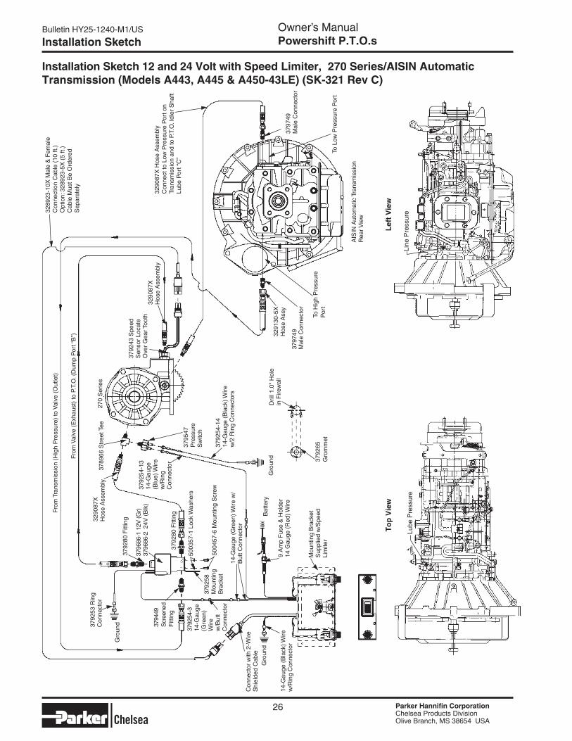
Installation Sketch 12 and 24 Volt with Speed Limiter, 270 Series/AISIN Automatic Transmission (Models A443, A445 & A450-43Le) (SK-321 Rev C)
26
From
Val
ve (
Exh
aust
) to
P.T
.O. (
Dum
p P
ort “
B”)
From
Tra
nsm
issi
on (
Hig
h P
ress
ure)
to V
alve
(O
utle
t)32
8923
-10X
Mal
e &
Fem
ale
Con
nect
ion
Cab
le (
10 ft
.)
Opt
ion:
328
923-
5X (
5 ft.
) C
able
Mus
t Be
Ord
ered
S
epar
atel
y
3290
87X
Hos
e A
ssem
bly
Con
nect
to L
ow P
ress
ure
Por
t on
Tran
smis
sion
and
to P
.T.O
. Idl
er S
haft
Lube
Por
t “C
”
3789
66 S
tree
t Tee
3290
87X
H
ose
Ass
embl
y
3792
43 S
peed
S
enso
r Lo
cate
O
ver
Gea
r Too
th32
9087
X
Hos
e A
ssem
bly
270
Ser
ies
3792
80 F
ittin
g
Gro
und
3792
54-1
3 14
-Gau
ge
(Blu
e) W
ire
w/R
ing
Con
nect
or
3794
49
Scr
eene
d F
ittin
g
Gro
und
Gro
und
Bat
tery
Mou
ntin
g B
rack
et
Sup
plie
d w
/Spe
ed
Lim
iter
3795
47
Pre
ssur
e S
witc
h
3792
54-1
4 14
-Gau
ge (
Bla
ck) W
ire
w/2
Rin
g C
onne
ctor
s
3291
30-5
XH
ose
Ass
y
3797
49M
ale
Con
nect
or
To H
igh
Pre
ssur
e P
ort
AIS
IN A
utom
atic
Tra
nsm
issi
on
Rea
r Vie
w
To L
ow P
ress
ure
Por
t
3797
49
Mal
e C
onne
ctor
3792
65
Gro
mm
et
Dril
l 1.0
" H
ole
in F
irew
all
9 A
mp
Fus
e &
Hol
der
14 G
auge
(R
ed) W
ire14
-Gau
ge (
Bla
ck) W
ire
w/R
ing
Con
nect
or
Con
nect
or w
ith 2
-Wire
S
hiel
ded
Cab
le
14-G
auge
(G
reen
) Wire
w/
But
t Con
nect
or
5003
57-1
Loc
k W
ashe
rs
5004
57-6
Mou
ntin
g S
crew
3792
58
Mou
ntin
g B
rack
et
3792
53 R
ing
Con
nect
or
3792
54-3
14
-Gau
ge
(Gre
en)
W
ire
w/B
utt
Con
nect
or
3796
86-1
12V
(Gr)
3796
86-2
24V
(B
lk)
3792
80 F
ittin
g
To
p V
iew
Lef
t V
iew
Line
Pre
ssur
e
▼
Lube
Pre
ssur
e
▼
Parker Hannifin CorporationChelsea Products DivisionOlive Branch, MS 38654 USA
Parker Hannifin CorporationChelsea Products DivisionOlive Branch, MS 38654 USA
Bulletin HY25-1240-M1/US Owner’s ManualPowershift P.T.O.s
Parker Hannifin CorporationChelsea Products DivisionOlive Branch, MS 38654 USA
Parker Hannifin CorporationChelsea Products DivisionOlive Branch, MS 38654 USA
Installation Sketch
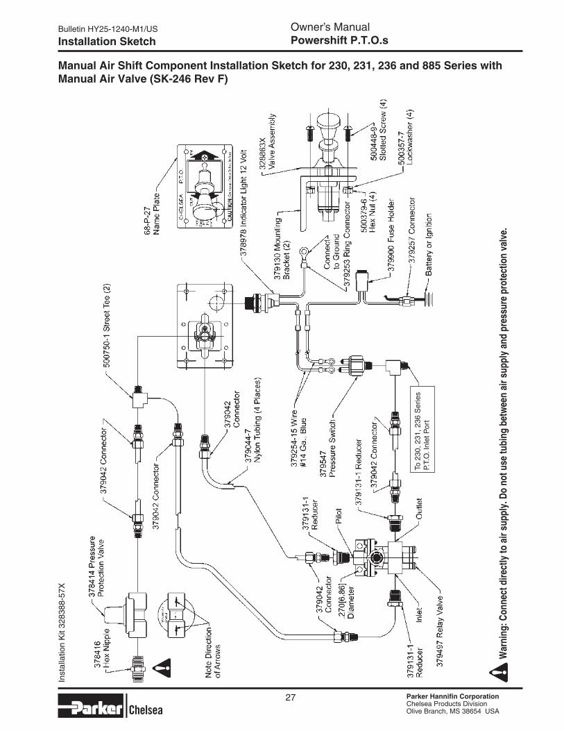
Manual Air Shift Component Installation Sketch for 230, 231, 236 and 885 Series with Manual Air Valve (SK-246 Rev F)
27
War
ning
: Con
nect
dire
ctly
to a
ir su
pply
. Do
not u
se tu
bing
bet
wee
n ai
r sup
ply
and
pres
sure
pro
tect
ion
valv
e.
To 2
30, 2
31, 2
36 S
erie
s P.
T.O
. Inl
et P
ort
Inst
alla
tion
Kit
3283
88-5
7X
Bulletin HY25-1240-M1/US Owner’s ManualPowershift P.T.O.s
Parker Hannifin CorporationChelsea Products DivisionOlive Branch, MS 38654 USA
Parker Hannifin CorporationChelsea Products DivisionOlive Branch, MS 38654 USA
Parker Hannifin CorporationChelsea Products DivisionOlive Branch, MS 38654 USA
Parker Hannifin CorporationChelsea Products DivisionOlive Branch, MS 38654 USA
Installation Sketch
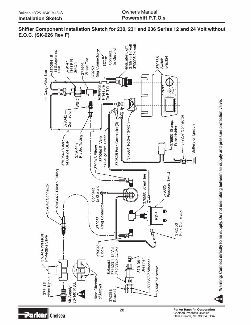
Shifter Component Installation Sketch for 230, 231 and 236 Series 12 and 24 Volt without e.O.C. (SK-226 Rev F)
28
War
ning
: Con
nect
dire
ctly
to a
ir su
pply
. Do
not u
se tu
bing
bet
wee
n ai
r sup
ply
and
pres
sure
pro
tect
ion
valv
e.
Parker Hannifin CorporationChelsea Products DivisionOlive Branch, MS 38654 USA
Parker Hannifin CorporationChelsea Products DivisionOlive Branch, MS 38654 USA
Bulletin HY25-1240-M1/US Owner’s ManualPowershift P.T.O.s
Parker Hannifin CorporationChelsea Products DivisionOlive Branch, MS 38654 USA
Parker Hannifin CorporationChelsea Products DivisionOlive Branch, MS 38654 USA
Installation Sketch
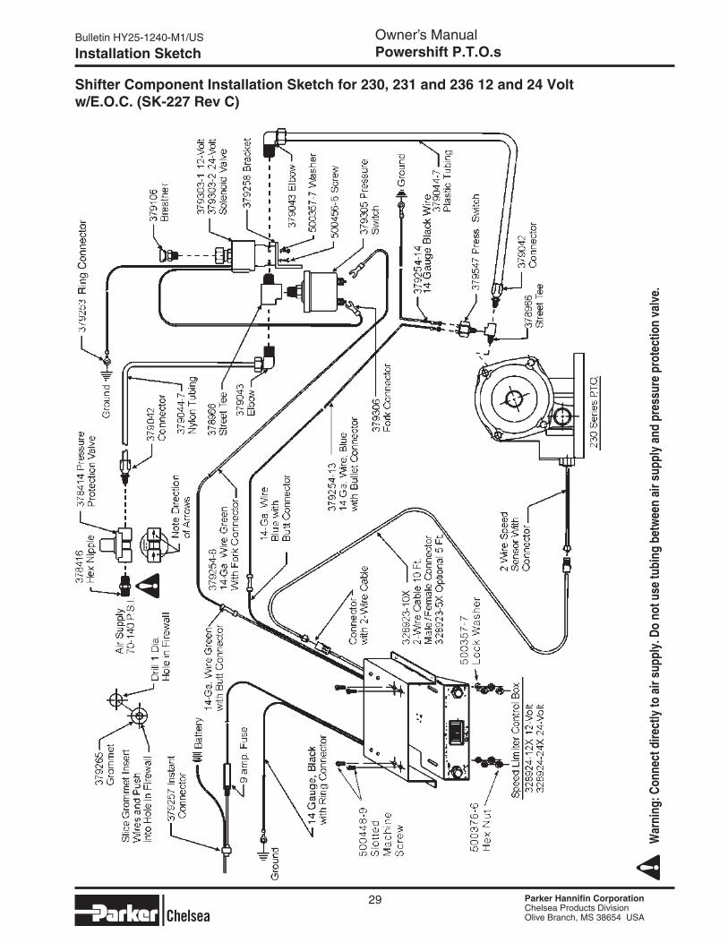
Shifter Component Installation Sketch for 230, 231 and 236 12 and 24 Volt w/e.O.C. (SK-227 Rev C)
29
War
ning
: Con
nect
dire
ctly
to a
ir su
pply
. Do
not u
se tu
bing
bet
wee
n ai
r sup
ply
and
pres
sure
pro
tect
ion
valv
e.
Bulletin HY25-1240-M1/US Owner’s ManualPowershift P.T.O.s
Parker Hannifin CorporationChelsea Products DivisionOlive Branch, MS 38654 USA
Parker Hannifin CorporationChelsea Products DivisionOlive Branch, MS 38654 USA
Parker Hannifin CorporationChelsea Products DivisionOlive Branch, MS 38654 USA
Parker Hannifin CorporationChelsea Products DivisionOlive Branch, MS 38654 USA
Installation Sketch
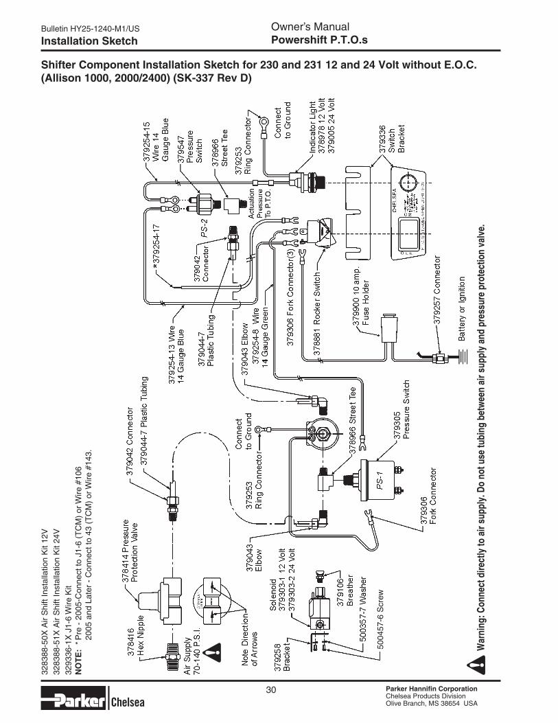
Shifter Component Installation Sketch for 230 and 231 12 and 24 Volt without E.O.C. (Allison 1000, 2000/2400) (SK-337 Rev D)
30
War
ning
: Con
nect
dire
ctly
to a
ir su
pply
. Do
not u
se tu
bing
bet
wee
n ai
r sup
ply
and
pres
sure
pro
tect
ion
valv
e.
3283
88-5
0X A
ir S
hift
Inst
alla
tion
Kit
12V
3283
88-5
1X A
ir S
hift
Inst
alla
tion
Kit
24V
3293
36-1
X J
1-6
Wire
Kit
NO
TE
: * P
re -
200
5-C
onne
ct to
J1-
6 (T
CM
) or
Wire
#10
6
200
5 an
d La
ter
- C
onne
ct to
43
(TC
M)
or W
ire #
143.
5004
57-6
Scr
ew
Parker Hannifin CorporationChelsea Products DivisionOlive Branch, MS 38654 USA
Parker Hannifin CorporationChelsea Products DivisionOlive Branch, MS 38654 USA
Bulletin HY25-1240-M1/US Owner’s ManualPowershift P.T.O.s
Parker Hannifin CorporationChelsea Products DivisionOlive Branch, MS 38654 USA
Parker Hannifin CorporationChelsea Products DivisionOlive Branch, MS 38654 USA
Installation Sketch
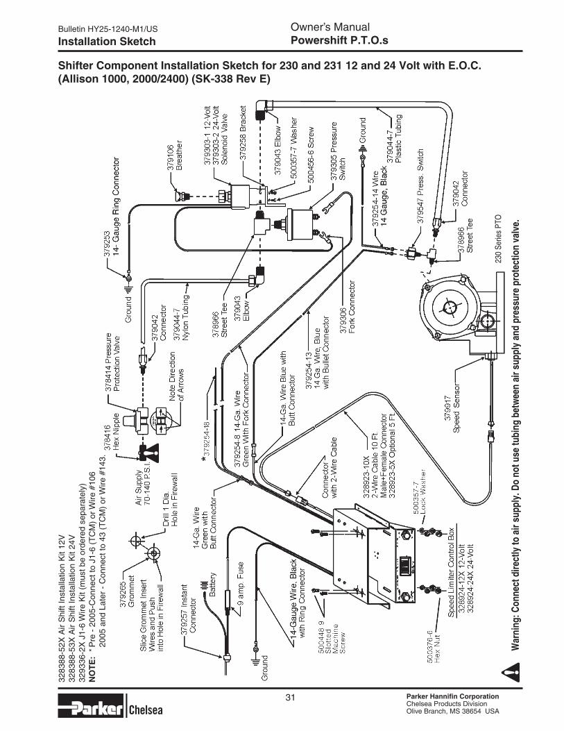
Shifter Component Installation Sketch for 230 and 231 12 and 24 Volt with E.O.C. (Allison 1000, 2000/2400) (SK-338 Rev E)
31
War
ning
: Con
nect
dire
ctly
to a
ir su
pply
. Do
not u
se tu
bing
bet
wee
n ai
r sup
ply
and
pres
sure
pro
tect
ion
valv
e.
3283
88-5
2X A
ir S
hift
Inst
alla
tion
Kit
12V
3283
88-5
3X A
ir S
hift
Inst
alla
tion
Kit
24V
3293
36-2
X J
1-6
Wire
Kit
(mus
t be
orde
red
sepa
rate
ly)
NO
TE
: * P
re -
200
5-C
onne
ct to
J1-
6 (T
CM
) or
Wire
#10
6
200
5 an
d La
ter
- C
onne
ct to
43
(TC
M)
or W
ire #
143.
230
Serie
s PT
O
Bulletin HY25-1240-M1/US Owner’s ManualPowershift P.T.O.s
Parker Hannifin CorporationChelsea Products DivisionOlive Branch, MS 38654 USA
Parker Hannifin CorporationChelsea Products DivisionOlive Branch, MS 38654 USA
Parker Hannifin CorporationChelsea Products DivisionOlive Branch, MS 38654 USA
Parker Hannifin CorporationChelsea Products DivisionOlive Branch, MS 38654 USA
Installation Sketch
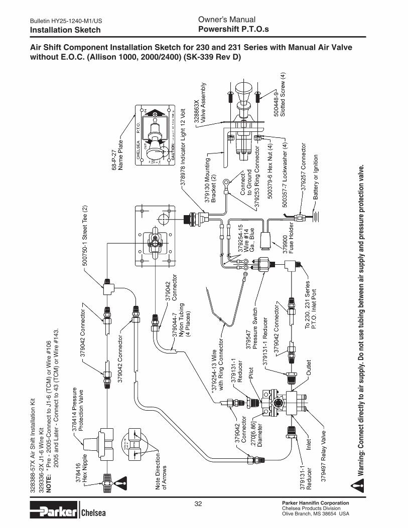
Air Shift Component Installation Sketch for 230 and 231 Series with Manual Air Valve without E.O.C. (Allison 1000, 2000/2400) (SK-339 Rev D)
32
War
ning
: Con
nect
dire
ctly
to a
ir su
pply
. Do
not u
se tu
bing
bet
wee
n ai
r sup
ply
and
pres
sure
pro
tect
ion
valv
e.
3283
88-5
7X A
ir S
hift
Inst
alla
tion
Kit
3293
36-2
X J
1-6
Wire
Kit
NO
TE
: * P
re -
200
5-C
onne
ct to
J1-
6 (T
CM
) or
Wire
#10
6
200
5 an
d La
ter
- C
onne
ct to
43
(TC
M)
or W
ire #
143.
*
Parker Hannifin CorporationChelsea Products DivisionOlive Branch, MS 38654 USA
Parker Hannifin CorporationChelsea Products DivisionOlive Branch, MS 38654 USA
Bulletin HY25-1240-M1/US Owner’s ManualPowershift P.T.O.s
Parker Hannifin CorporationChelsea Products DivisionOlive Branch, MS 38654 USA
Parker Hannifin CorporationChelsea Products DivisionOlive Branch, MS 38654 USA
Installation Sketch
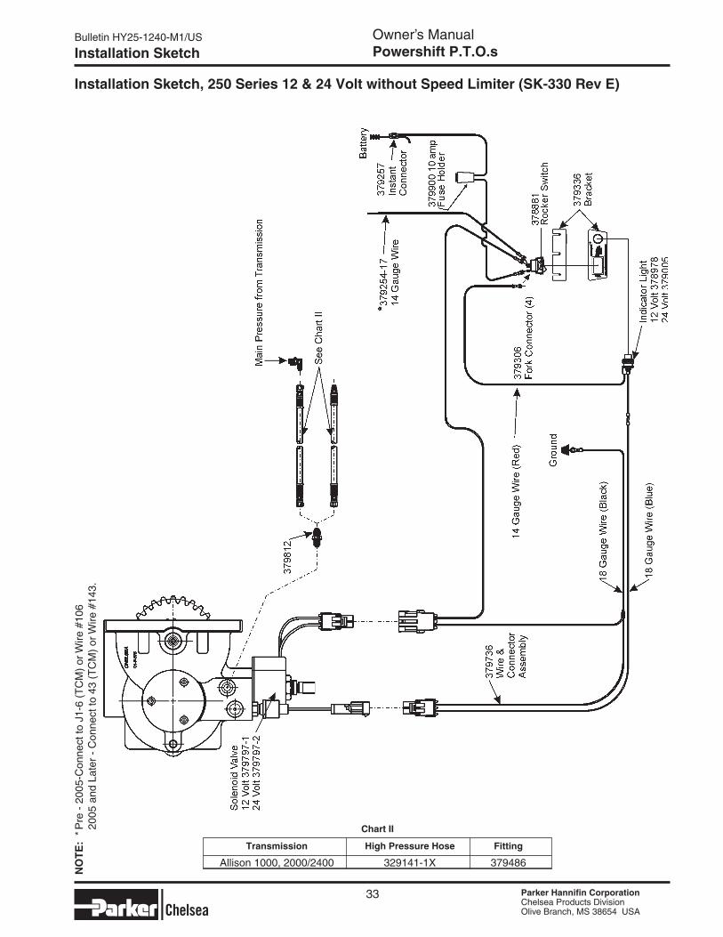
Installation Sketch, 250 Series 12 & 24 Volt without Speed Limiter (SK-330 Rev E)
Transmission High Pressure Hose Fitting
Allison 1000, 2000/2400 329141-1X 379486
Chart II
33
*
NO
TE
: * P
re -
200
5-C
onne
ct to
J1-
6 (T
CM
) or
Wire
#10
6
200
5 an
d La
ter
- C
onne
ct to
43
(TC
M)
or W
ire #
143.
Bulletin HY25-1240-M1/US Owner’s ManualPowershift P.T.O.s
Parker Hannifin CorporationChelsea Products DivisionOlive Branch, MS 38654 USA
Parker Hannifin CorporationChelsea Products DivisionOlive Branch, MS 38654 USA
Parker Hannifin CorporationChelsea Products DivisionOlive Branch, MS 38654 USA
Parker Hannifin CorporationChelsea Products DivisionOlive Branch, MS 38654 USA
Installation Sketch
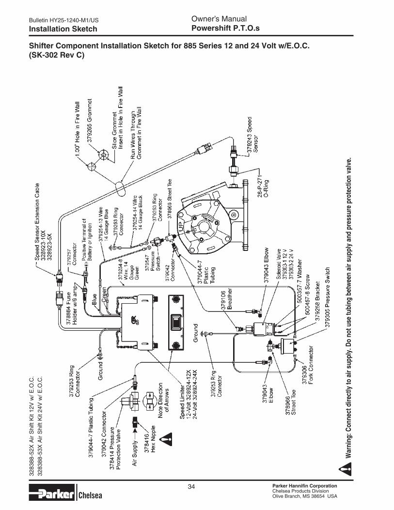
Shifter Component Installation Sketch for 885 Series 12 and 24 Volt w/e.O.C. (SK-302 Rev C)
34
W
arni
ng: C
onne
ct d
irect
ly to
air
supp
ly. D
o no
t use
tubi
ng b
etw
een
air s
uppl
y an
d pr
essu
re p
rote
ctio
n va
lve.
3283
88-5
2X A
ir S
hift
Kit
12V
w/ E
.O.C
.
3283
88-5
3X A
ir S
hift
Kit
24V
w/ E
.O.C
.
Parker Hannifin CorporationChelsea Products DivisionOlive Branch, MS 38654 USA
Parker Hannifin CorporationChelsea Products DivisionOlive Branch, MS 38654 USA
Bulletin HY25-1240-M1/US Owner’s ManualPowershift P.T.O.s
Parker Hannifin CorporationChelsea Products DivisionOlive Branch, MS 38654 USA
Parker Hannifin CorporationChelsea Products DivisionOlive Branch, MS 38654 USA
Installation Sketch
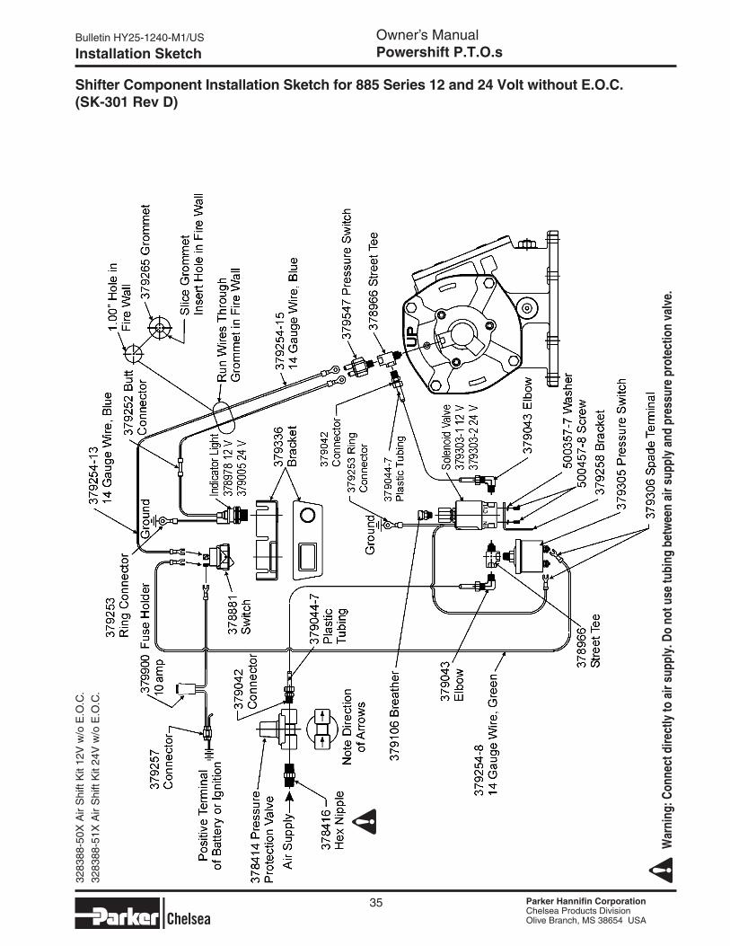
Shifter Component Installation Sketch for 885 Series 12 and 24 Volt without E.O.C. (SK-301 Rev D)
35
W
arni
ng: C
onne
ct d
irect
ly to
air
supp
ly. D
o no
t use
tubi
ng b
etw
een
air s
uppl
y an
d pr
essu
re p
rote
ctio
n va
lve.
3283
88-5
0X A
ir S
hift
Kit
12V
w/o
E.O
.C.
3283
88-5
1X A
ir S
hift
Kit
24V
w/o
E.O
.C.
Bulletin HY25-1240-M1/US Owner’s ManualPowershift P.T.O.s
Parker Hannifin CorporationChelsea Products DivisionOlive Branch, MS 38654 USA
Parker Hannifin CorporationChelsea Products DivisionOlive Branch, MS 38654 USA
Parker Hannifin CorporationChelsea Products DivisionOlive Branch, MS 38654 USA
Parker Hannifin CorporationChelsea Products DivisionOlive Branch, MS 38654 USA
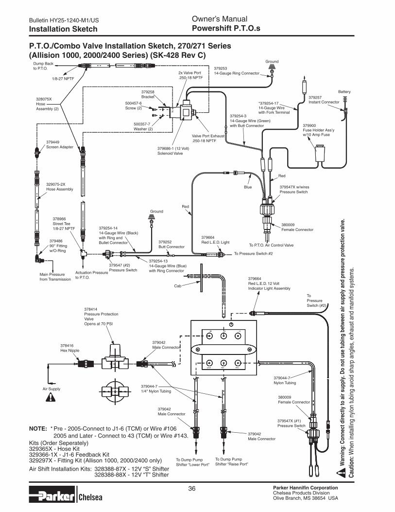
Cab
379664Red L.E.D. 12 VoltIndicator Light Assembly
To Pressure Switch (#2)
380009Female Connector
379547X (#1)Pressure Switch
To Dump PumpShifter “Raise Port”
To Dump PumpShifter “Lower Port”
379042Male Connector
379042Male Connector
379044-71/4" Nylon Tubing
379042Male Connector
378414Pressure Protection ValveOpens at 70 PSI
378416 Hex Nipple
Air Supply
379044-7Nylon Tubing
Installation Sketch
36
Ground
To P.T.O. Air Control Valve
P.T.O./Combo Valve Installation Sketch, 270/271 Series (Allision 1000, 2000/2400 Series) (SK-428 Rev C)
379253 14-Gauge Ring Connector2x Valve Port
.250-18 NPTF
379258 Bracket
500457-6 Screw (2)
500357-7 Washer (2)
379686-1 (12 Volt) Solenoid Valve
Valve Port Exhaust.250-18 NPTF
1/8-27 NPTF
328075XHose Assembly (2)
Dump Back to P.T.O.
379449 Screen Adapter
329075-2X Hose Assembly
378966 Street Tee1/8-27 NPTF
379486 90° Fitting w/O-Ring
Main Pressure from Transmission
Actuation Pressure to P.T.O.
Ground
379254-1414-Gauge Wire (Black)with Ring and Bullet Connector
379547 (#2)Pressure Switch
379252Butt Connector
379254-1314-Gauge Wire (Blue)with Ring Connector
379664Red L.E.D. Light
To Pressure Switch #2
380009Female Connector
379547X w/wires Pressure Switch
379254-314-Gauge Wire (Green)with Butt Connector
*379254-17 14-Gauge Wire with Fork Terminal
Battery
379257 Instant Connector
379900 Fuse Holder Ass’yw/10 Amp Fuse
Red
Blue
Red
Kits (Order Seperately)329365X - Hose Kit329366-1X - J1-6 Feedback Kit329297X - Fitting Kit (Allison 1000, 2000/2400 only)
Caut
ion:
Whe
n in
stal
ling
nylo
n tu
bing
avo
id s
harp
ang
les,
exh
aust
and
man
ifold
sys
tem
s.
W
arni
ng: C
onne
ct d
irect
ly to
air
supp
ly. D
o no
t use
tubi
ng b
etw
een
air s
uppl
y an
d pr
essu
re p
rote
ctio
n va
lve.
Air Shift Installation Kits: 328388-87X - 12V “S” Shifter 328388-88X - 12V “T” Shifter
NOTE: * Pre - 2005-Connect to J1-6 (TCM) or Wire #106 2005 and Later - Connect to 43 (TCM) or Wire #143.
Parker Hannifin CorporationChelsea Products DivisionOlive Branch, MS 38654 USA
Parker Hannifin CorporationChelsea Products DivisionOlive Branch, MS 38654 USA
Bulletin HY25-1240-M1/US Owner’s ManualPowershift P.T.O.s
Parker Hannifin CorporationChelsea Products DivisionOlive Branch, MS 38654 USA
Parker Hannifin CorporationChelsea Products DivisionOlive Branch, MS 38654 USA
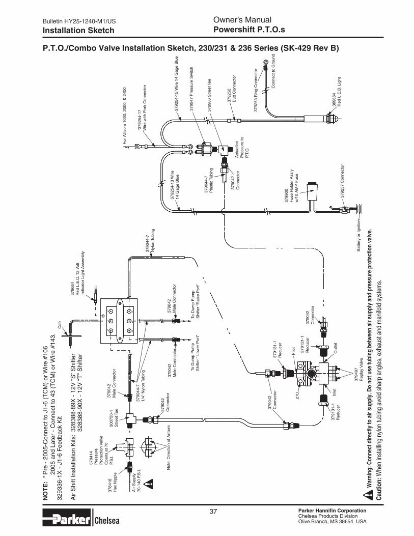
Installation Sketch
P.T.O./Combo Valve Installation Sketch, 230/231 & 236 Series (SK-429 Rev B)
37
Cab
3796
64R
ed L
.E.D
. 12
Vol
tIn
dica
tor
Ligh
t Ass
embl
y
3790
42M
ale
Con
nect
or
To D
ump
Pum
pS
hifte
r “R
aise
Por
t”To
Dum
p P
ump
Shi
fter
“ Lo
wer
Por
t”
3790
42M
ale
Con
nect
or37
9042
Mal
e C
onne
ctor
3790
44-7
1/4"
Nyl
on T
ubin
g
3790
42C
onne
ctor
Not
e: D
irect
ion
of A
rrow
s
3784
14P
ress
ure
Pro
tect
ion
Val
veO
pens
at 7
0 P.
S.I.
5007
50-1
Str
eet T
ee
.270
3790
42C
onne
ctor
3791
31-1
Rec
ucer
Pilo
t
3791
31-1
R
educ
er37
9042
Con
nect
or
Out
let
3794
97R
epla
y V
alve
Inle
t37
9131
-1R
educ
er
3790
44-7
Nyl
on T
ubin
g
Bat
tery
or
Igni
tion
3792
52B
utt C
onne
ctor
3789
66 S
tree
t Tee
3795
47 P
ress
ure
Sw
itch
*379
254-
17W
ire w
ith F
ork
Con
nect
or
For
Alli
som
100
0, 2
000,
& 2
400
3792
54-1
5 W
ire 1
4 G
age
Blu
e37
9254
-13
Wire
14 G
age
Blu
e
3790
44-7
Pla
stic
Tub
ing
Act
uatio
n P
ress
ure
to
P.T.
O.
3790
42
Con
nect
or
3792
53 R
ing
Con
nect
or
Con
nect
to G
roun
d
3696
64R
ed L
.E.D
. Lig
ht
3799
00F
use
Hol
der
Ass
’yw
/10
AM
P F
use
3792
57 C
onne
ctor
Air
Sup
ply
70-1
40 P
.S.I.
3784
16H
ex N
ippl
e
3293
36-1
X -
J1-
6 F
eedb
ack
Kit
Air
Shi
ft In
stal
latio
n K
its:
3283
88-8
9X -
12V
“S
” Shi
fter
32
8388
-90X
- 1
2V “
T” S
hifte
r
Caut
ion:
Whe
n in
stal
ling
nylo
n tu
bing
avo
id s
harp
ang
les,
exh
aust
and
man
ifold
sys
tem
s.
War
ning
: Con
nect
dire
ctly
to a
ir su
pply
. Do
not u
se tu
bing
bet
wee
n ai
r sup
ply
and
pres
sure
pro
tect
ion
valv
e.
NO
TE
: * P
re -
200
5-C
onne
ct to
J1-
6 (T
CM
) or
Wire
#10
6
200
5 an
d La
ter
- C
onne
ct to
43
(TC
M)
or W
ire #
143.
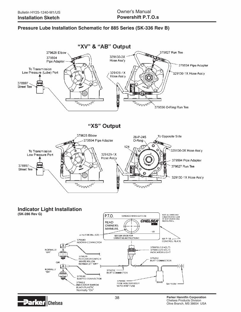
Bulletin HY25-1240-M1/US Owner’s ManualPowershift P.T.O.s
Parker Hannifin CorporationChelsea Products DivisionOlive Branch, MS 38654 USA
Parker Hannifin CorporationChelsea Products DivisionOlive Branch, MS 38654 USA
Parker Hannifin CorporationChelsea Products DivisionOlive Branch, MS 38654 USA
Parker Hannifin CorporationChelsea Products DivisionOlive Branch, MS 38654 USA
Installation Sketch
Pressure Lube Installation Schematic for 885 Series (SK-336 Rev B)
38
Indicator Light Installation (SK-286 Rev G)
Normally “On”
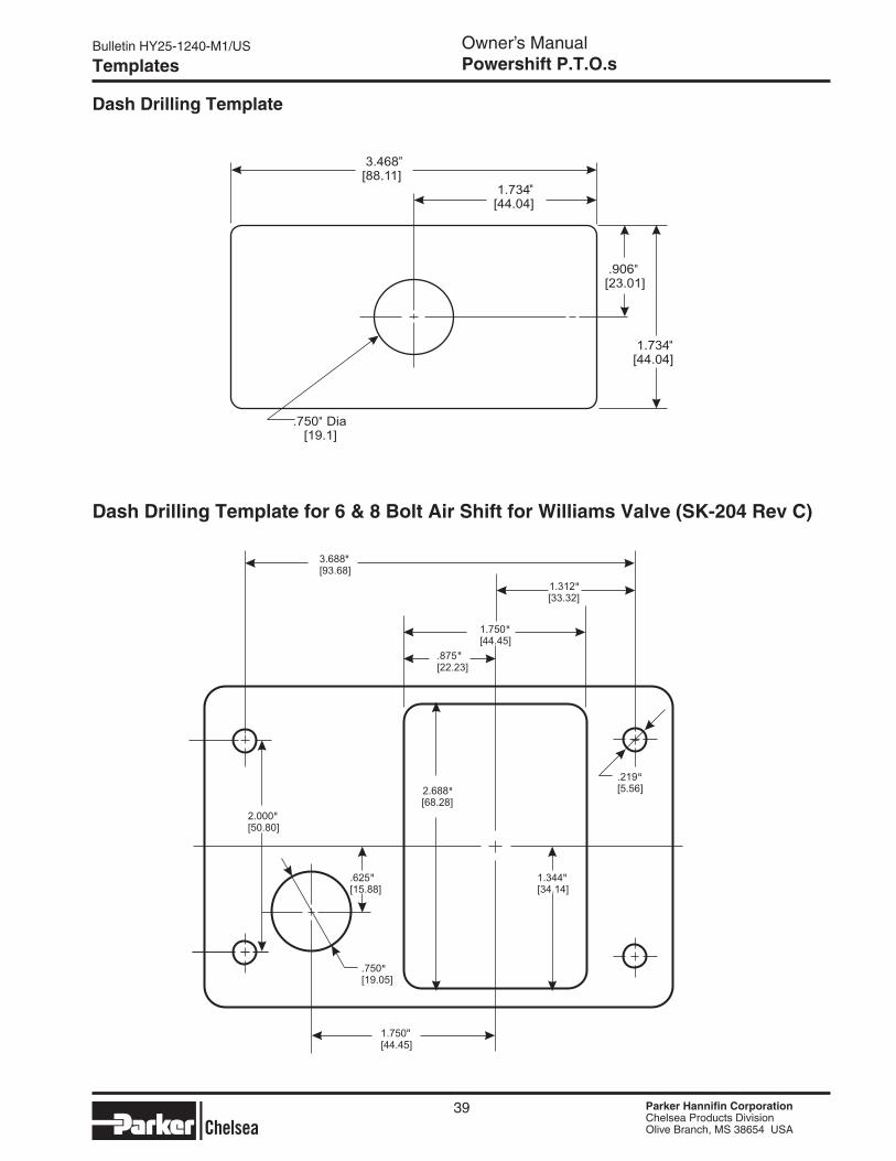
Parker Hannifin CorporationChelsea Products DivisionOlive Branch, MS 38654 USA
Parker Hannifin CorporationChelsea Products DivisionOlive Branch, MS 38654 USA
Bulletin HY25-1240-M1/US Owner’s ManualPowershift P.T.O.s
Parker Hannifin CorporationChelsea Products DivisionOlive Branch, MS 38654 USA
Parker Hannifin CorporationChelsea Products DivisionOlive Branch, MS 38654 USA
Templates
39
Dash Drilling Template
Dash Drilling Template for 6 & 8 Bolt Air Shift for Williams Valve (SK-204 Rev C)
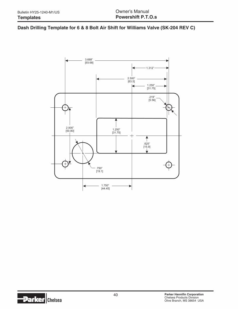
Bulletin HY25-1240-M1/US Owner’s ManualPowershift P.T.O.s
Parker Hannifin CorporationChelsea Products DivisionOlive Branch, MS 38654 USA
Parker Hannifin CorporationChelsea Products DivisionOlive Branch, MS 38654 USA
Parker Hannifin CorporationChelsea Products DivisionOlive Branch, MS 38654 USA
Parker Hannifin CorporationChelsea Products DivisionOlive Branch, MS 38654 USA
Templates
40
Dash Drilling Template for 6 & 8 Bolt Air Shift for Williams Valve (SK-204 ReV C)
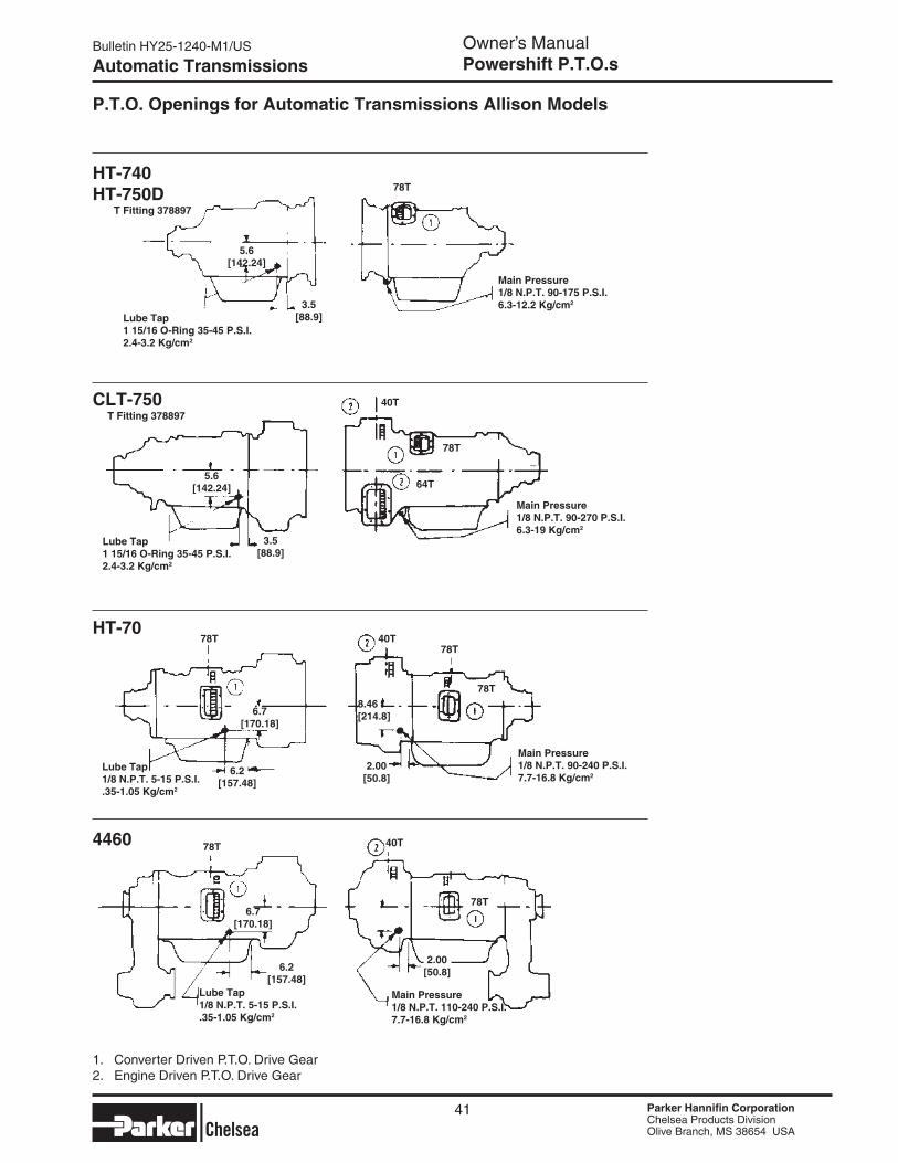
Parker Hannifin CorporationChelsea Products DivisionOlive Branch, MS 38654 USA
Parker Hannifin CorporationChelsea Products DivisionOlive Branch, MS 38654 USA
Bulletin HY25-1240-M1/US Owner’s ManualPowershift P.T.O.s
Parker Hannifin CorporationChelsea Products DivisionOlive Branch, MS 38654 USA
Parker Hannifin CorporationChelsea Products DivisionOlive Branch, MS 38654 USA
Automatic Transmissions
P.T.O. Openings for Automatic Transmissions Allison Models
HT-740HT-750D
CLT-750
HT-70
T Fitting 378897
5.6[142.24]
3.5[88.9]Lube Tap
1 15/16 O-Ring 35-45 P.S.I.2.4-3.2 Kg/cm2
T Fitting 378897
5.6[142.24]
3.5[88.9]
Lube Tap1 15/16 O-Ring 35-45 P.S.I.2.4-3.2 Kg/cm2
78T
Lube Tap1/8 N.P.T. 5-15 P.S.I..35-1.05 Kg/cm2
6.7[170.18]
6.2[157.48]
1. Converter Driven P.T.O. Drive Gear2. Engine Driven P.T.O. Drive Gear
2.00[50.8]
8.46[214.8]
4460
6.7[170.18]
6.2[157.48]
Main Pressure1/8 N.P.T. 110-240 P.S.I.7.7-16.8 Kg/cm2
Lube Tap1/8 N.P.T. 5-15 P.S.I..35-1.05 Kg/cm2
2.00[50.8]
41
Main Pressure1/8 N.P.T. 90-175 P.S.I.6.3-12.2 Kg/cm2
Main Pressure1/8 N.P.T. 90-270 P.S.I.6.3-19 Kg/cm2
Main Pressure1/8 N.P.T. 90-240 P.S.I.7.7-16.8 Kg/cm2
78T
40T
40T78T
78T
78T 40T
78T
64T
78T
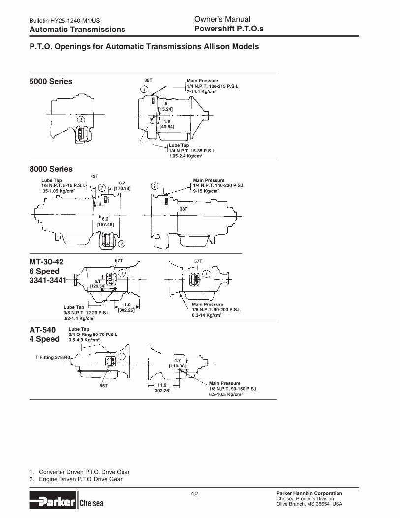
Bulletin HY25-1240-M1/US Owner’s ManualPowershift P.T.O.s
Parker Hannifin CorporationChelsea Products DivisionOlive Branch, MS 38654 USA
Parker Hannifin CorporationChelsea Products DivisionOlive Branch, MS 38654 USA
Parker Hannifin CorporationChelsea Products DivisionOlive Branch, MS 38654 USA
Parker Hannifin CorporationChelsea Products DivisionOlive Branch, MS 38654 USA
Automatic Transmissions
MT-30-426 Speed3341-3441
AT-5404 Speed
5.1[129.54]
11.9[302.26]
Lube Tap3/8 N.P.T. 12-20 P.S.I..92-1.4 Kg/cm2
T Fitting 3788404.7
[119.38]
11.9[302.26]
Main Pressure1/8 N.P.T. 90-200 P.S.I.6.3-14 Kg/cm2
Main Pressure1/8 N.P.T. 90-150 P.S.I.6.3-10.5 Kg/cm2
Lube Tap3/4 O-Ring 50-70 P.S.I.3.5-4.9 Kg/cm2
P.T.O. Openings for Automatic Transmissions Allison Models
8000 SeriesLube Tap1/8 N.P.T. 5-15 P.S.I..35-1.05 Kg/cm2
6.7[170.18]
6.2[157.48]
1. Converter Driven P.T.O. Drive Gear2. Engine Driven P.T.O. Drive Gear
Main Pressure1/4 N.P.T. 140-230 P.S.I.9-15 Kg/cm2
5000 Series
.6[15.24]
1.6[40.64]
Lube Tap1/4 N.P.T. 15-35 P.S.I.1.05-2.4 Kg/cm2
Main Pressure1/4 N.P.T. 100-215 P.S.I.7-14.4 Kg/cm2
42
38T
43T
38T
57T 57T
55T
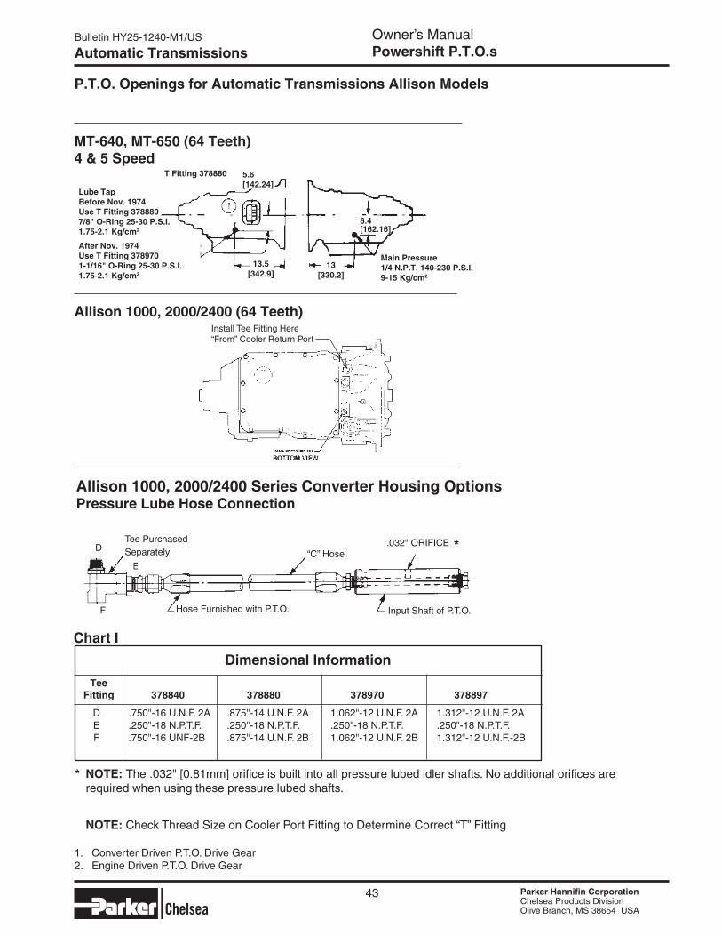
Parker Hannifin CorporationChelsea Products DivisionOlive Branch, MS 38654 USA
Parker Hannifin CorporationChelsea Products DivisionOlive Branch, MS 38654 USA
Bulletin HY25-1240-M1/US Owner’s ManualPowershift P.T.O.s
Parker Hannifin CorporationChelsea Products DivisionOlive Branch, MS 38654 USA
Parker Hannifin CorporationChelsea Products DivisionOlive Branch, MS 38654 USA
Automatic Transmissions
P.T.O. Openings for Automatic Transmissions Allison Models
1. Converter Driven P.T.O. Drive Gear2. Engine Driven P.T.O. Drive Gear
43
Allison 1000, 2000/2400 Series Converter Housing OptionsPressure Lube Hose Connection
Tee Purchased SeparatelyD
F
E
Hose Furnished with P.T.O.
* NOTe: The .032" [0.81mm] orifice is built into all pressure lubed idler shafts. No additional orifices are required when using these pressure lubed shafts.
NOTe: Check Thread Size on Cooler Port Fitting to Determine Correct “T” Fitting
“C” Hose
Input Shaft of P.T.O.
*.032" ORIFICE
Allison 1000, 2000/2400 (64 Teeth)Install Tee Fitting Here“From” Cooler Return Port
MT-640, MT-650 (64 Teeth)4 & 5 Speed
Lube TapBefore Nov. 1974Use T Fitting 3788807/8" O-Ring 25-30 P.S.I.1.75-2.1 Kg/cm2
After Nov. 1974Use T Fitting 3789701-1/16" O-Ring 25-30 P.S.I.1.75-2.1 Kg/cm2
13[330.2]
5.6[142.24]
13.5[342.9]
T Fitting 378880
Main Pressure1/4 N.P.T. 140-230 P.S.I.9-15 Kg/cm2
6.4[162.16]
Tee Fitting 378840 378880 378970 378897
D .750"-16 U.N.F. 2A .875"-14 U.N.F. 2A 1.062"-12 U.N.F. 2A 1.312"-12 U.N.F. 2A E .250"-18 N.P.T.F. .250"-18 N.P.T.F. .250"-18 N.P.T.F. .250"-18 N.P.T.F. F .750"-16 UNF-2B .875"-14 U.N.F. 2B 1.062"-12 U.N.F. 2B 1.312"-12 U.N.F.-2B
Dimensional Information
Chart I
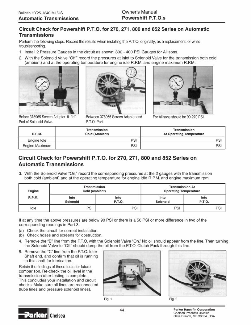
Bulletin HY25-1240-M1/US Owner’s ManualPowershift P.T.O.s
Parker Hannifin CorporationChelsea Products DivisionOlive Branch, MS 38654 USA
Parker Hannifin CorporationChelsea Products DivisionOlive Branch, MS 38654 USA
Parker Hannifin CorporationChelsea Products DivisionOlive Branch, MS 38654 USA
Parker Hannifin CorporationChelsea Products DivisionOlive Branch, MS 38654 USA
Automatic Transmissions
Circuit Check for Powershift P.T.O. for 270, 271, 800 and 852 Series on Automatic Transmissions
3. With the Solenoid Valve “On,” record the corresponding pressures at the 2 gauges with the transmission both cold (ambient) and at the operating temperature for engine idle R.P.M. and engine maximum rpm.
If at any time the above pressures are below 90 PSI or there is a 50 PSI or more difference in two of the corresponding readings in Part 3:
(a) Check the circuit for correct installation. (b) Check hoses and screens for obstruction.
4. Remove the “B” line from the P.T.O. with the Solenoid Valve “On.” No oil should appear from the line. Then turning the Solenoid Valve to “Off” should dump the oil from the P.T.O. Clutch Pack through this line.
5. Remove the “C” line from the P.T.O. Idler Shaft end, and confirm that oil is running to this shaft for lubrication.
Retain the findings of these tests for future comparison. Re-check the oil level in the transmission after testing is complete.This concludes your installation and circuit checks. Make sure all lines are reconnected (lube lines and pressure solenoid lines).
Perform the following steps. Record the results when installing the P.T.O. originally, as a replacement, or while troubleshooting.
1. Install 2 Pressure Gauges in the circuit as shown: 300 - 400 PSI Gauges for Allisons.
2. With the Solenoid Valve “Off,” record the pressures at inlet to Solenoid Valve for the transmission both cold (ambient) and at the operating temperature for engine idle R.P.M. and engine maximum R.P.M.
Circuit Check for Powershift P.T.O. for 270, 271, 800 and 852 Series on Automatic Transmissions
For Allisons should be 90-270 PSI.Between 378966 Screen Adapter and P.T.O. Port.
Fig. 1 Fig. 2
44
Before 378965 Screen Adapter @ “In” Port of Solenoid Valve.
Transmission Transmission R.P.M. Cold (Ambient) At Operating Temperature
Engine Idle PSI PSI
Engine Maximum PSI PSI
Transmission Transmission At engine Cold (ambient) Operating Temperature
R.P.M. Into Into Into Into Solenoid P.T.O. Solenoid P.T.O.
Idle PSI PSI PSI PSI

Parker Hannifin CorporationChelsea Products DivisionOlive Branch, MS 38654 USA
Parker Hannifin CorporationChelsea Products DivisionOlive Branch, MS 38654 USA
Bulletin HY25-1240-M1/US Owner’s ManualPowershift P.T.O.s
Parker Hannifin CorporationChelsea Products DivisionOlive Branch, MS 38654 USA
Parker Hannifin CorporationChelsea Products DivisionOlive Branch, MS 38654 USA
Installing Rotatable Flanges
The rotatable flange is shipped loose with the P.T.O. units for ease of installation. After determining the flange position, attach the flange to the P.T.O. bearing cap using the capscrews provided in the bag kit. Bag kit number 328170-207X (6-bolt family) will contain (3) capscrews (378447-6) and 328170-208X (230/231, 236 and 270/271 Series) will contain (4) capscrews for attaching the flange to the P.T.O. bearing cap. After installing the capscrews make sure to torque the screws to 16-20 Lbs. ft.Consideration should be taken on the size and weight of the pump being installed. (see pages 3 and 4)
RA Flange Shown
NOTE: Reinstalling or tightening of a rotatable flange after it has become loose is not recommended. If a P.T.O. has run for a length of time after the flange has become loose, the flange and / or bearing cap may not be to manufacturing tolerance.
▼
▼
▼▼
Installation Instructions
45

Bulletin HY25-1240-M1/US Owner’s ManualPowershift P.T.O.s
Parker Hannifin CorporationChelsea Products DivisionOlive Branch, MS 38654 USA
Parker Hannifin CorporationChelsea Products DivisionOlive Branch, MS 38654 USA
P.T.O. Shifting Procedure & Precautions for 1000, 2000/2400, AT, MT & HT Series Transmissions
CAUTION: This vehicle is equipped with a Power Take-Off. Shut the engine off before working on the Power Take-Off or getting below the vehicle.
Consult operating instructions before using. (See Sun Visor)
POWER TAKE-OFF OPERATION VEHICLE STATIONARY.
1. Automatic Transmission with Powershift P.T.O.
Engage P.T.O. with the engine at idle speed.
2. Manually Shifted Transmission with Powershift P.T.O.
Engage P.T.O. with the engine at idle speed.
NOTE: Powershift P.T.O.: The engine must be at idle or below 1,000 R.P.M. when the P.T.O. is initially en-gaged. See the transmission manufacturer’s instructions for special procedures.
IMPORTANT: Failure to follow proper shifting or operating sequences will result in premature P.T.O. failure with possible damage to other equipment.
NOTE: There is a torque converter lock up feature available with the 1000/2000/2400 Series transmis-sions. The torque converter lock up feature comes on and is controlled by the Transmission Control Module (TCM) at 1100 engine R.P.M. when a signal is provided to the “P.T.O. Enable” circuit of the TCM by the P.T.O. switch. Lock up will only come on in the “NEUTRAL” and “PARK” positions. The lock up clutch does not come on automatically in “DRIVE” at 1100 R.P.M.
Automatic Transmissions
46 Parker Hannifin CorporationChelsea Products DivisionOlive Branch, MS 38654 USA
Parker Hannifin CorporationChelsea Products DivisionOlive Branch, MS 38654 USA

Parker Hannifin CorporationChelsea Products DivisionOlive Branch, MS 38654 USA
Parker Hannifin CorporationChelsea Products DivisionOlive Branch, MS 38654 USA
Notes
47 Parker Hannifin CorporationChelsea Products DivisionOlive Branch, MS 38654 USA
Parker Hannifin CorporationChelsea Products DivisionOlive Branch, MS 38654 USA

48
Notes
Parker Hannifin CorporationChelsea Products DivisionOlive Branch, MS 38654 USA
Parker Hannifin CorporationChelsea Products DivisionOlive Branch, MS 38654 USA
Parker Hannifin CorporationChelsea Products DivisionOlive Branch, MS 38654 USA
Parker Hannifin CorporationChelsea Products DivisionOlive Branch, MS 38654 USA

Notes
49 Parker Hannifin CorporationChelsea Products DivisionOlive Branch, MS 38654 USA
Parker Hannifin CorporationChelsea Products DivisionOlive Branch, MS 38654 USA
Parker Hannifin CorporationChelsea Products DivisionOlive Branch, MS 38654 USA
Parker Hannifin CorporationChelsea Products DivisionOlive Branch, MS 38654 USA
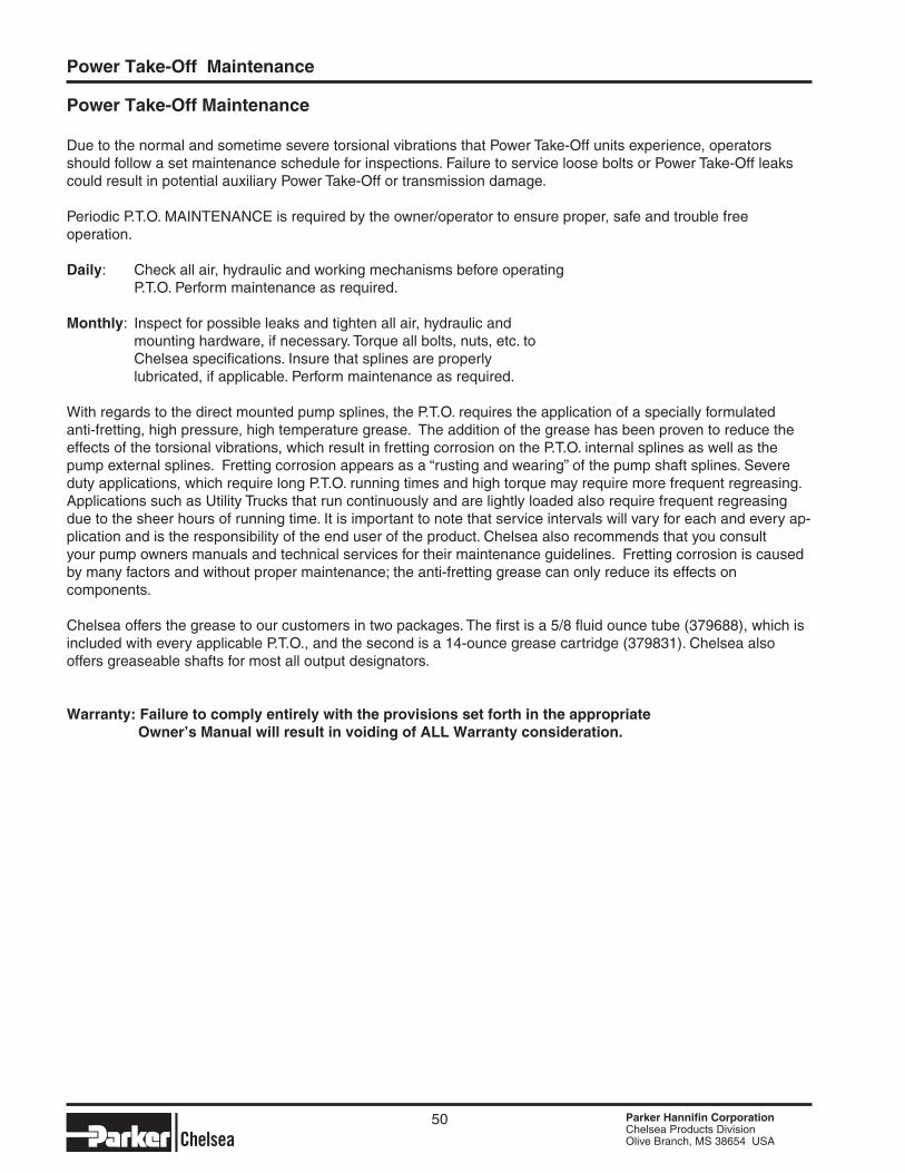
Parker Hannifin CorporationChelsea Products DivisionOlive Branch, MS 38654 USA
50
Power Take-Off Maintenance
Due to the normal and sometime severe torsional vibrations that Power Take-Off units experience, operators should follow a set maintenance schedule for inspections. Failure to service loose bolts or Power Take-Off leaks could result in potential auxiliary Power Take-Off or transmission damage.
Periodic P.T.O. MAINTENANCE is required by the owner/operator to ensure proper, safe and trouble free operation.
Daily: Check all air, hydraulic and working mechanisms before operating P.T.O. Perform maintenance as required.
Monthly: Inspect for possible leaks and tighten all air, hydraulic and mounting hardware, if necessary. Torque all bolts, nuts, etc. to Chelsea specifications. Insure that splines are properly lubricated, if applicable. Perform maintenance as required.
With regards to the direct mounted pump splines, the P.T.O. requires the application of a specially formulated anti-fretting, high pressure, high temperature grease. The addition of the grease has been proven to reduce the effects of the torsional vibrations, which result in fretting corrosion on the P.T.O. internal splines as well as the pump external splines. Fretting corrosion appears as a “rusting and wearing” of the pump shaft splines. Severe duty applications, which require long P.T.O. running times and high torque may require more frequent regreasing. Applications such as Utility Trucks that run continuously and are lightly loaded also require frequent regreasing due to the sheer hours of running time. It is important to note that service intervals will vary for each and every ap-plication and is the responsibility of the end user of the product. Chelsea also recommends that you consult your pump owners manuals and technical services for their maintenance guidelines. Fretting corrosion is caused by many factors and without proper maintenance; the anti-fretting grease can only reduce its effects on components.
Chelsea offers the grease to our customers in two packages. The first is a 5/8 fluid ounce tube (379688), which is included with every applicable P.T.O., and the second is a 14-ounce grease cartridge (379831). Chelsea also offers greaseable shafts for most all output designators. Warranty: Failure to comply entirely with the provisions set forth in the appropriate Owner’s Manual will result in voiding of ALL Warranty consideration.
Power Take-Off Maintenance
The items described in this document and other documents or descriptions provided by Parker Hannifin Corporation, its subsidiaries and its autho-rized distributors are hereby offered for sale at prices to be established by Parker Hannifin Corporation, its subsidiaries and its authorized distributors. This offer and its acceptance by any customer ("Buyer") shall be governed by all of the following Terms and Conditions. Buyer’s order for any such items, when communicated to Parker Hannifin Corporation, its subsidiary or an authorized distributor ("Seller") verbally or in writing, shall constitute acceptance of this offer.
discard or otherwise dispose of any special tooling or other property in its sole discretion at any time.8. Buyer’s Property: Any designs, tools, patterns, materials, drawings, confidential information or equipment furnished by Buyer or any other items which become Buyer’s property, may be considered obsolete and may be destroyed by Seller after two (2) consecutive years have elapsed without Buyer placing an order for the items which are manufactured using such property, Seller shall not be responsible for any loss or damage to such property while it is in Seller’s possession or control.9. Taxes: Unless otherwise indicated on the face hereof, all prices and charges are exclusive of excise, sales, use, property, occupational or like taxes which may be imposed by any taxing authority upon the manufacture, sale or delivery of the items sold hereunder. If any such taxes must be paid by Seller or if Seller is liable for the collection of such tax, the amount thereof shall be in addition to the amounts for the items sold. Buyer agrees to pay all such taxes or to reimburse Seller therefore upon receipt of its invoice. If Buyer claims exemption from any sales, use or other tax imposed by any taxing authority, Buyer shall save Seller harmless from and against any such tax, together with any interest or penalties thereon which may be assessed if the items are held to be taxable.10. Indemnity For Infringement of Intellectual Property Rights: Seller shall have no liability for infringement of any patents, trademarks, copyrights, trade dress, trade secrets or similar rights except as provided in this Part 10. Seller will defend and indemnify Buyer against allegations of infringement of U.S. Patents, U.S. Trademarks, copyrights, trade dress and trade secrets (hereinafter ‘Intellectual Property Rights’). Seller will defend at its expense and will pay the cost of any settlement or damages awarded in an action brought against Buyer based on an allegation that an item sold pursuant to this contract infringes the Intellectual Property Rights of a third party. Seller’s obligation to defend and indemnify Buyer is contingent on Buyer notifying Seller within ten (10) days after Buyer becomes aware of such allegations of infringement, and Seller having sole control over the defense of any allegations or actions including all negotiations for settlement or compromise. If an item sold hereunder is subject to a claim that it infringes the Intellectual Property Rights of a third party, Seller may, at its sole expense and option, procure for Buyer the right to continue using said item, replace or modify said item so as to make it noninfringing, or offer to accept return of said item and return the purchase price less a reasonable allowance for depreciation. Notwithstanding the foregoing, Seller shall have no liability for claims of infringement based on information provided by Buyer, or directed to items delivered hereunder for which the designs are specified in whole or part by Buyer, or infringements resulting from the modification, com-bination or use in a system of any item sold hereunder. The foregoing provisions of this Part 10 shall constitute Seller’s sole and exclusive liability and Buyer’s sole and exclusive remedy for infringement of Intel-lectual Property Rights.If a claim is based on information provided by Buyer or if the design for an item delivered hereunder is specified in whole or in part by Buyer, Buyer shall defend and indemnify Seller for all costs, expenses or judgments resulting from any claim that such item infringes any patent, trademark, copyright, trade dress, trade secret or any similar right.11. Force Majeure: Seller does not assume the risk of and shall not be liable for delay or failure to perform any of Seller’s obligations by reason of circumstances beyond the reasonable control of Seller (hereinafter ‘Events of Force Majeure’). Events of Force Majeure shall include without limitation, accidents, acts of God, strikes or labor disputes, acts, laws, rules or regulations of any government or government agency, fires, floods, delays or failures in delivery of carriers or suppliers, shortages of materials and any other cause beyond Seller’s control.12. Entire Agreement/Governing Law: The terms and conditions set forth herein, together with any amendments, modifications and any different terms or conditions expressly accepted by Seller in writing, shall constitute the entire Agreement concerning the items sold, and there are no oral or other representations or agreements which pertain there/to. This Agreement shall be governed in all respects by the law of the State of Ohio. No actions arising out of the sale of the items sold hereunder or this Agreement may be brought by either party more than two (2) years after the cause of action accrues. 6/08-P
1. Terms and Conditions of Sale: All descriptions, quotations, pro-posals, offers, acknowledgments, acceptances and sales of Seller’s products are subject to and shall be governed exclusively by the terms and conditions stated herein. Buyer’s acceptance of any offer to sell is limited to these terms and conditions. Any terms or conditions in addi-tion to, or inconsistent with those stated herein, proposed by Buyer in any acceptance of an offer by Seller, are hereby objected to. No such additional, different or inconsistent terms and conditions shall become part of the contract between Buyer and Seller unless expressly accepted in writing by Seller. Seller’s acceptance of any offer to purchase by Buyer is expressly conditional upon Buyer’s assent to all the terms and condi-tions stated herein, including any terms in addition to, or inconsistent with those contained in Buyer’s offer, Acceptance of Seller’s products shall in all events constitute such assent.2. Payment: Payment shall be made by Buyer net 30 days from the date of delivery of the items purchased hereunder. Amounts not timely paid shall bear interest at the maximum rate permitted by law for each month or portion thereof that the Buyer is late in making payment. Any claims by Buyer for omissions or shortages in a shipment shall be waived un-less Seller receives notice thereof within 30 days after Buyer’s receipt of the shipment.3. Delivery: Unless otherwise provided on the face hereof, delivery shall be made F.O.B. Seller’s plant. Regardless of the method of deliv-ery, however, risk of loss shall pass to Buyer upon Seller’s delivery to a carrier. Any delivery dates shown are approximate only and Seller shall have no liability for any delays in delivery.4. Warranty: Seller warrants that the items sold hereunder shall be free from defects in material or workmanship for a period of:(A) All Power Take-Off units 18 months from date of sale.(B) Except 267, 269, 277, 278, 246, 247, 250, and 859 series two (2) years from date of installation. THIS WARRANTY COMPRISES THE SOLE AND ENTIRE WARRANTY PERTAINING TO ITEMS PROVIDED HEREUNDER. SELLER MAKES NO OTHER WARRANTY, GUAR-ANTEE, OR REPRESENTATION OF ANY KIND WHATSOEVER. ALL OTHER WARRANTIES, INCLUDING BUT NOT LIMITED TO, MERCHANTABILITY AND FITNESS FOR PURPOSE, WHETHER EXPRESS, IMPLIED, OR ARISING BY OPERATION OF LAW, TRADE USAGE, OR COURSE OF DEALING ARE HEREBY DISCLAIMED. NOTWITHSTANDING THE FOREGOING, THERE ARE NO WARRAN-TIES WHATSOEVER ON ITEMS BUILT OR ACQUIRED WHOLLY OR PARTIALLY, TO BUYER’S DESIGNS OR SPECIFICATIONS.5. Limitation Of Remedy: SELLER’S LIABILITY ARISING FROM OR IN ANY WAY CONNECTED WITH THE ITEMS SOLD OR THIS CONTRACT SHALL BE LIMITED EXCLUSIVELY TO REPAIR OR REPLACEMENT OF THE ITEMS SOLD OR REFUND OF THE PURCHASE PRICE PAID BY BUYER, AT SELLER’S SOLE OPTION. IN NO EVENT SHALL SELLER BE LIABLE FOR ANY INCIDENTAL, CONSEQUENTIAL OR SPECIAL DAMAGES OF ANY KIND OR NATURE WHATSOEVER, INCLUDING BUT NOT LIMITED TO LOST PROFITS ARISING FROM OR IN ANY WAY CONNECTED WITH THIS AGREEMENT OR ITEMS SOLD HEREUNDER, WHETHER ALLEGED TO ARISE FROM BREACH OF CONTRACT, EXPRESS OR IMPLIED WARRANTY, OR IN TORT, INCLUDING WITHOUT LIMITATION, NEGLIGENCE, FAILURE TO WARN OR STRICT LIABILITY.6. Changes, Reschedules and Cancellations: Buyer may request to modify the designs or specifications for the items sold hereunder as well as the quantities and delivery dates thereof, or may request to cancel all or part of this order, however, no such requested modification or cancellation shall become part of the contract between Buyer and Seller unless accepted by Seller in a written amendment to this Agreement. Acceptance of any such requested modification or cancellation shall be at Seller’s discretion, and shall be upon such terms and conditions as Seller may require.7. Special Tooling: A tooling charge may be imposed for any special tooling, including without limitation, dies, fixtures, molds and patterns, acquired to manufacture items sold pursuant to this contract. Such special tooling shall be and remain Seller’s property notwithstanding payment of any charges by Buyer. In no event will Buyer acquire any interest in apparatus belonging to Seller which is utilized in the manufacture of the items sold hereunder, even if such apparatus has been specially converted or adapted for such manufacture and notwithstanding any charges paid by Buyer. Unless otherwise agreed, Seller shall have the right to alter,
Offer of Sale
Parker Hannifin CorporationChelsea Products DivisionOlive Branch, MS 38654 USA
51

Parker Hannifin CorporationChelsea Products Division8225 Hacks Cross RoadOlive Branch, Mississippi 38654 USATel: (662) 895-1011Fax: (662) 895-1019www.parker.com/chelsea
FP 11/08 4M