Overview of Smart System Research Facility (FREA-G ... · 1 Overview of Smart System Research...
28
1 Overview of Smart System Research Facility (FREA-G) Fukushima Renewable Energy Institute, AIST Jun Hashimoto Kenji OTANI Fukushima Renewable Energy Institute, AIST (FREA) National Institute of Advanced Industrial Science and Technology (AIST) 4 th International Workshop on Grid Simulator Testing of Energy System and Wind Turbine Powertrains April 25-26, 2017@NREL ESIF
Transcript of Overview of Smart System Research Facility (FREA-G ... · 1 Overview of Smart System Research...

1
OverviewofSmartSystemResearchFacility(FREA-G)FukushimaRenewableEnergyInstitute,AIST
JunHashimotoKenjiOTANI
FukushimaRenewableEnergyInstitute,AIST(FREA)
NationalInstituteofAdvancedIndustrialScienceandTechnology(AIST)
4th InternationalWorkshoponGridSimulatorTestingofEnergySystem
andWindTurbinePowertrainsApril25-26,2017@NRELESIF

AIST- Overview• AISTisanationalresearchinstitutewith
– 2300scientists,100Byen/year– 10sitesalloverJapan– workwithindustry,universities,internationally
� + �*�"��'%�#& � + �*�"��!!#�
AISTFukushima
2

FREA: Fukushima Renewable Energy Institute, AIST
�
��
��
��
����
��
Koriyama
Shinkansen80min. to Tokyo
FukushimaprefectureKoriyama, Fukushima
2013,Oct. organization founded2014, Apr. open in Koriyama
Missions
• International R&D base for renewable energy• New industry promotion in damaged area
Location
10 billion yen for start up(land, buildings, equipment)3 billion yen/y, 400 people and more
Schedule
Budget
3

4
TotalViewofFREA
Rated Output: 300kW
Wind Power SystemHydrogen Bldg.
Annex BuildingClean Rooms, Experiment Rooms
Main BuildingResearch Labs, Area 6,9002
PV Power SystemRated Output: 500kW
Smart System Research Facility (FREA-G)
Energy Management Bldg.
Opened in April 2016
MCH Bldg.

• Open in April 2016 at FREA• Operating by AIST as a user’s facility• Subsidy from METI: 73 million U.S. dollars• Maximum Test Capabilities
pEUTs (DERs): Up to 3 MWpDC power source (PV Simulator): 3.3 MWpAC power source (Grid Simulator): 5.0 MVApEnvironmental chamber: -40 to 85 degree in CpEMC testing room
5
Our Smart System R&D Test Platformcalled FREA-G

FREA-GConcept• SubstantiallyexpandtheaforementionedFREAfacilitytobuildtheworld’smostadvancedtestfacility.
Ø Conduct required tests to secure power quality for the grid connection of distributed generations.
Ø Conduct various PCS tests (anti-islanding test, FRT test, etc.)
Ø Maximum capacity of AC simulator: 5MVA.Ø Maximum capacity of EUT: 3MW.
A. Grid Connection Test Bed
Ø Conduct high-temperature acceleration and heat cycle tests with PCS where real environment is simulated to evaluate long-term reliability, and also safety-related tests including surge voltage test.
B. Safety Test Bed
Ø Conduct tests to measure electromagnetic radiation from PCS and to check if PCS’s functions and behavior would be inhibited by external electromagnetic wave.
C. EMC Test Bed
Ø Evaluate different capabilities (e.g. automatic control function to maximize output depending on the weather) of distributed generations (PV, batteries, etc.) and PCS as one single system.
D. System Performance Test Bed
6

Achievements in the first half-year• The first tests were successfully completed in all test
rooms (grid-connection test, environment test and EMC test).
• Cooperation with JET (Japan Electrical Safety & Environment Technology Laboratories) has been efficient to meet various test requirements from manufactures.
• Data for certification tests were provided to a few certification bodies to get their certification. – e.g. Thai PEA (Provincial Electricity Authority) added one Japanese PV
inverter in their certified inverter list based on our data in June 2016.
7

8
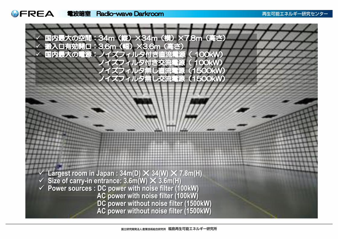
����Radiowave Darkroom
�����Distribution Line Impedance
������DC Power Connecting Board
����������AC Power Connecting Board
(Low Voltage)
� ����SCADA & DAQ
���Viewing Window
Real Time Digital Simulator
1Single EUT testing 1EUT test with HILs 1DER testing platform
'������ !��� (�!�����������!&��� !���� )�& !�����������
���$���
���!$���
� ������� !����
���%�����!&
� �����$�!��� �& !���������!���������
���$�������"�
���!$������"�
���!�������!
����!� !���#�������!
���!�����������

9
SmartSystemR&DTestPlatform
RequirementAnalysis
AcceptanceTest
High LevelDesign
SystemTest
DetailedDesign
Unit Design
IntegrationTest
Unit Test
ManufacturersIntegrators Test Labs
Scoping DesignDevelopment Buy / BuildImplementation Verification
Verification Feedback to R&D
AIST - FREA
Smart System
R&D
Test Platform
Control Protocols
DER Unit Test
Integration of System Test and Simulation
Field DatabaseSite Acceptance
Test
Test MethodsTest PlatformTests / Certifications
Contributions to Expansions ofSmarter DER Systems

10
AC 6600V bus
Environmental Safety
Test Lab3.0MVA max
AC Grid 66kV
Grid Simulator 1.66MVA
PVInverter500kW
PV Array500kW
EMCTest Lab
(10m)1.5MVA max
Grid Interconnection Test Lab No.13.0MVA max
Grid Interconnection Test Lab No.21.0MVA max
PV SimulatorNo1
550kw
PV SimulatorNo6
550kw
PV SimulatorMulti Output
220kW
Grid Simulator 1.66MVA
Grid Simulator 1.66MVA
Load Bank(LCR) No1
1MVA
Power Storage Unit Sodium-ion Battery
1.2MW
AC Grid Simulator Bus 6600VAC Grid Bus 6600VAC Grid Simulator Bus 400V
AC Test Bus 3MVAAC Test Bus 1MVAAC Test Bus 1MVA
PV Array 500kWDC PV Simulator Bus 3MW
LIN
111
SystemPerformance
Test Lab1.0MVA max
AC 400V bus
Load Bank(LCR) No2
1MVA
Load Bank(LCR) No3
1MVA

11
AchievementsofFREA-G
Objective Standard Testing item
Test for Thailand certificationIEC Anti-islanding ; tested by JET
IEC Low Voltage Ride Through (LVRT) ; tested by JET
1,500V PV inverter test for U.S. certification
UL1741 Anti-islanding
UL1741 Low Voltage Ride Through (LVRT)
CEC CEC efficiency
1,500V PV inverter test for Europe certification (TBD)
VDE Low Voltage Ride Through (LVRT)
VDE Anti-islanding
Developing test- Low temperature operation test
- Reliability test (damp heat test)
Proposal for new standard
IEC NP Energy efficiency evaluation for grid connected PV inverter
IEC NP Basic requirement of AC simulator for PV inverter testing
IEC NP Basic requirement of DC simulator for PV inverter testing
n SinceFREA-GwasopeninApril2016,following12projectshavealready beencarriedout(someofthemarestillinprogress)
n FREA-GhascapabilitiesoftestingforcertificationsinvariousregionssuchasAsia,U.S.andEuropeandvariousstandardssuchasUL,VDE,IECandCEC.
Achievements of FREA-G (Since April this year)

wo uSmart System Research Facility
Main Building
Annex Building
f ×Demonstration Field
h ×k 3PHP FG C CR IC 2 CMES 6 G P C .6 3 2.

Radiowave Darkroom
wo u GMB GCR LD M S C C C MAF 3 AGIG S

7 4MGB 0L CA GL C 7 7
℃Simulation Power Distribution Line DC Power Connecting Board
AC Power Connecting Board (Low Voltage)
o uSCADA & DAQ
Viewing Window

8 4MGB 0L CA GL C 7 8
DC Power Connecting Board
AC Power Connecting Board (High Voltage)
o uSCADA & DAQ
AC Power Connecting Board (Low Voltage)

4MGB 0L CA GL C 7
Multi Output PV Simulator
AC Power Connecting Board (Low Voltage)
AC Power Connecting Board (High Voltage)
BGL R C 1 MHMLL
ü a () T() T, -
ü ( T(
ü a g f×r H
g f×r Hg f×r Hg f×r H
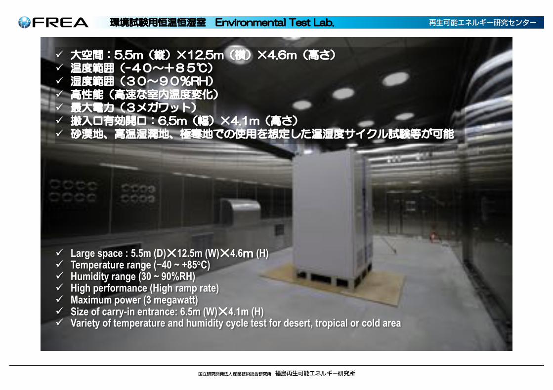
ü Largest room in Japan : 34m(D) T 34(W) T 7.8m(H)ü Size of carry-in entrance: 3.6m(W) T 3.6m(H)ü Power sources : DC power with noise filter (100kW)
AC power with noise filter (100kW)DC power without noise filter (1500kW)AC power without noise filter (1500kW)
2 GML C I C 7
ü T T)
üü 5
üü i sw
ü T)
ü V V a e ngl×
ü Large space : 5.5m (D)T12.5m (W)T4.6 (H)ü Temperature range (−40 ~ +85oC)ü Humidity range (30 ~ 90%RH)ü High performance (High ramp rate)ü Maximum power (3 megawatt)ü Size of carry-in entrance: 6.5m (W)T4.1m (H)ü Variety of temperature and humidity cycle test for desert, tropical or cold area

4MGB G PI LM
ü i sw
ü ×w ×w
ü slt sl
ü a o u a V e
ü 3 asw
a
ü High power (5 megawatt at the maximum)ü High voltage (400 volt / 6000 volt)ü High performance (back-to-back power sources)ü AC power source to simulate frequency and voltage of
electric power systems in the worldü Use for Fault Ride Through (FRT) test
Single Unit: 1670 kilowattPossible to run 3 units in parallel

.MM S G PI LM
ü i sw
ü ×w
ü o m V o m a W
a e
ü cd a b
sw×we
ü High power (3.3 megawatt at the maximum)ü High voltage (2000 volt at the maximum)ü DC power source to simulate PV array systems, which is
crystalline silicon, thin film silicon, etc.ü Possible to simulate time-series of power output
according to the fluctuation of solar irradiance
Single power : 550 kilowatt1000 volt
Configure a series-parallel circuit with 6 units

21
70 7L B G PI LM
ü i sw
ü m vfo ya
sound barrier
RLC Load Simulator
ü Large scale (3 megawatt)ü Use for anti-islanding test for PCSs of Solar
photovoltaic system

22
SIRFNSmartGridCollaboration
• Primarygoal:Developanddemonstrateaconsensus-basedinteroperabilitycertificationstandardforadvancedDistributedEnergyResources(DERs).– Designandcompareadvancedinteroperabilitytest-beds.– Performround-robintestingofadvancedDER.– Comparetestresults,communicationsmethods,andautomationprocedures.– GraduallyimprovedrafttestproceduresforadvancedDERwiththegoalofbecomingan
internationally-acceptedstandard.
SIRFN- Acoordinatednetworkofsmartgridresearchfacilitiesfrom:
IEA(InternationalEnergyAgency)
CleanEnergyMinisterial(CEM)
InternationalSmartGridActionNetwork(ISGAN)
SmartGridInternationalResearchFacilityNetwork(SIRFN)
SmartGridDistributionAutomation
PowerSystemsTestingAdvancedLaboratoryTestingMethods
TestProtocolsforAdvancedInverterFunctions
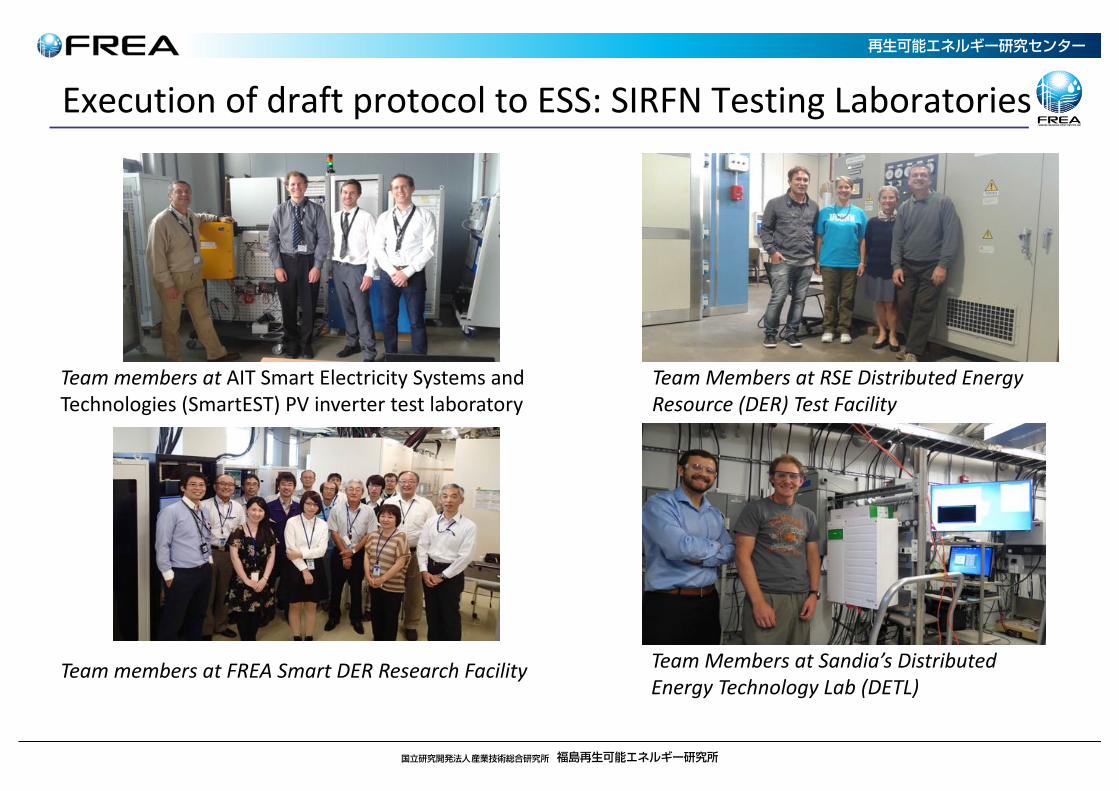
ExecutionofdraftprotocoltoESS:SIRFNTestingLaboratories
TeammembersatAITSmartElectricitySystemsandTechnologies(SmartEST)PVinvertertestlaboratory
TeamMembersatSandia’sDistributedEnergyTechnologyLab(DETL)
TeammembersatFREASmartDERResearchFacility
TeamMembersatRSEDistributedEnergyResource(DER)TestFacility

24
BESSTestProtocolLabRequirements
The four laboratories in the Smart Grid International Research Facility Network (SIRFN) have been formulating evaluation and certification protocol for BESS interoperability and functionality.
n � +, ��#&, *'( *��#$#,0�!-&�,#'&+�� !#& ��#&������������ ���
Ø �'%%�&� ���'/ *����,'*3����4
Ø � )- +,���,#. ��'/ *3����4
Ø ��*��*#'*#,0��'$,���*3����4
Ø � )- +,�� ��,#. ��'/ *3����4
Ø �* )- &�0�+-(('*,��0���,#. ��'/ *����4
BESS interoperability test protocols Published from IEA ISGAN3http://www.iea-isgan.org4
CEI 0-16 (IT)
VDE-AR-N 4105
(DE, AT)UL 1741
SA (USA)
SIRFN ESS Protocol Requirements
IEC TR 61850-90-
7
Be harmonized and inclusive with existing international standards, International requirements and National Grid Codes

ReviewDataandRefineProtocols:CommandedPowerFactor
-1 -0.5 0 0.5 1-1
-0.5
0
0.5
1 FREA INV3 Test Results
p.u. Active Power
p.u.
Rea
ctiv
e Po
wer
System Ratingp.f. = 1p.f. = 0.95p.f. = 0.90p.f. = 0.85p.f. = 0.80p.f. = -0.95p.f. = -0.90p.f. = -0.85p.f. = -0.80
-1 -0.5 0 0.5 1-1
-0.5
0
0.5
1 RSE INV3 Test Results
p.u. Active Power
p.u.
Rea
ctiv
e Po
wer
System Ratingp.f.=1p.f.=0.2 underexcitedp.f.=0.6 underexcitedp.f.=0.2 overexcitedp.f.=0.6 overexcited

ReviewDataandRefineProtocols:CommandedActivePower
0 0.5 1 1.5 2-1
-0.8
-0.6
-0.4
-0.2
0
0.2
0.4
0.6
0.8
1 RSE ESS1 Test Results
Time (s)
p.u.
Act
ive
Pow
er
0 0.5 1 1.5-1
-0.8
-0.6
-0.4
-0.2
0
0.2
0.4
0.6
0.8
1 SNL ESS1 Test Results
Time (s)
p.u.
Act
ive
Pow
er
0 0.5 1 1.5 2 2.5 3-1
-0.8
-0.6
-0.4
-0.2
0
0.2
0.4
0.6
0.8
1 AIT ESS1 Test Results
Time (s)
p.u.
Act
ive
Pow
er
Rated Discharge (RSE)1/2 Rated Discharge (RSE)1/4 Rated Discharge (RSE)1/4 Rated Charge (RSE)1/2 Rated Charge (RSE)Rated Charge (RSE)
Rated Discharge (SNL)1/2 Rated Discharge (SNL)1/4 Rated Discharge (SNL)1/4 Rated Charge (SNL)1/2 Rated Charge (SNL)Rated Charge (SNL)
Rated Discharge (AIT)1/2 Rated Discharge (AIT)1/4 Rated Discharge (AIT)1/4 Rated Charge (AIT)1/2 Rated Charge (AIT)Rated Charge (AIT)

��,#.#,0��&����(��#$#,0�'!��������#&����• Open in April 2016 and conduct total 20 tests in last year• We keep upgrade this facility to adapt advanced functionality such as advanced inverter, HIL testing
etc.
DomesticCapability International Other• JET start inverter certification for Japanese Grid code at FREA-G
• Seven units has been tested by this scheme
• Up to 3MW EUT can test at FREA-G
• First 2.7MW/1500V EUT was tested in 2016 Dec.
• Capable to test Large capacity EUT for Interconnection test, Reliability test and EMC test
• Capability to test IEC standard and others
• First interconnect test for Thailand was tested and accepted by PEA (Thailand)
• JET accelerate international certification by using our facility
• PV system EMS testing was conducted at FREA-G
• Cutting edge new FACT equipment was tested (EMC, Reliability and Performance)
2016 March - May
Inverter test for Thailand
2016 April
Certification of inverter
FACT: TVR
2017 Jan.
2016 Dec.
Largest EMC testing facility in Japan


![Continuous Energy Improvement (CEI) Getting & Staying Energy Smart [Your Facility Logo Goes Here]](https://static.fdocuments.net/doc/165x107/56649da05503460f94a8bfc3/continuous-energy-improvement-cei-getting-staying-energy-smart-your-facility.jpg)