Overview of RFX -mod Results with Active MHD Control
43
IAEA 2006 Chengdu M. Agostini, C. Alessi, A. Alfier, V. Antoni, L. Apolloni, F. Auriemma, P. Bettini, T. Bolzonella, D. Bonfiglio, F. Bonomo, M. Brombin, A. Buffa, A. Canton, S. Cappello, L. Carraro, R. Cavazzana, M. Cavinato, G. Chitarin, A. Cravotta, S. Dal Bello, A. De Lorenzi, L. De Pasqual, D.F. Escande, A: Fassina, P. Franz, G. Gadani, E. Gaio, L. Garzotti, E. Gazza, L. Giudicotti, F. Gnesotto, M. Gobbin, L. Grando, S.C. Guo, P. Innocente, R. Lorenzini, A. Luchetta, G. Malesani, G. Manduchi, G. Marchiori, D. Marcuzzi, L. Marrelli, P. Martin, E. Martines, S. Martini, A. Masiello, F. Milani, M. Moresco, A. Murari, L. Novello, S. Ortolani, R. Paccagnella, R. Pasqualotto, S. Peruzzo, R. Piovan, P. Piovesan, A. Pizzimenti, N. Pomaro, M.E. Puiatti, G. Rostagni, F. Sattin, P. Scarin, G. Serianni, P. Sonato, E. Spada, A. Soppelsa, G. Spizzo, M. Spolaore, C. Taccon, C. Taliercio, D. Terranova, V. Toigo, M. Valisa, N. Vianello, P. Zaccaria, P. Zanca, B. Zaniol, L. Zanotto, E. Zilli, G. Zollino, M. Zuin Overview of RFX Overview of RFX - - mod Results mod Results with Active MHD Control with Active MHD Control S. Martini on behalf of the RFX team Consorzio RFX, Associazione EURATOM_ENEA sulla Fusione, Corso Stati Uniti 4, 35127 Padova, Italy
Transcript of Overview of RFX -mod Results with Active MHD Control
IAEA 2006 Chengdu
M. Agostini, C. Alessi, A. Alfier, V. Antoni, L. Apolloni, F. Auriemma, P. Bettini, T. Bolzonella, D. Bonfiglio, F. Bonomo, M. Brombin, A. Buffa, A. Canton, S. Cappello, L. Carraro, R. Cavazzana, M. Cavinato, G. Chitarin, A. Cravotta, S. Dal Bello, A. De Lorenzi, L. De Pasqual, D.F. Escande, A: Fassina, P. Franz, G. Gadani, E. Gaio, L. Garzotti, E. Gazza, L. Giudicotti, F. Gnesotto, M. Gobbin, L. Grando, S.C. Guo, P. Innocente, R. Lorenzini, A. Luchetta, G. Malesani, G. Manduchi, G. Marchiori, D. Marcuzzi, L. Marrelli, P. Martin, E. Martines, S. Martini, A. Masiello, F. Milani, M. Moresco, A. Murari, L. Novello, S. Ortolani, R. Paccagnella, R. Pasqualotto, S. Peruzzo, R. Piovan, P. Piovesan, A. Pizzimenti, N. Pomaro, M.E. Puiatti, G. Rostagni, F. Sattin, P. Scarin, G. Serianni, P. Sonato, E. Spada, A. Soppelsa, G. Spizzo, M. Spolaore, C. Taccon, C. Taliercio, D. Terranova, V. Toigo, M. Valisa, N. Vianello, P. Zaccaria, P. Zanca, B. Zaniol, L. Zanotto, E. Zilli, G. Zollino, M. Zuin
Overview of RFXOverview of RFX --mod Results mod Results with Active MHD Controlwith Active MHD Control
S. Martini
on behalf of the RFX team
Consorzio RFX, Associazione EURATOM_ENEA sulla Fusione, Corso Stati Uniti 4, 35127 Padova, Italy

IAEA 2006 Chengdu
Outline of Talk Outline of Talk
1.1. Introduction: the RFP and its MHD modesIntroduction: the RFP and its MHD modes
2.2. RFXRFX--mod: new features for MHD controlmod: new features for MHD control
3.3. RFXRFX--mod vs RFX benchmarkmod vs RFX benchmark
4.4. Feedback stabilization of RWMsFeedback stabilization of RWMs
5.5. Mode rotation & Confinement @ 1 MA Mode rotation & Confinement @ 1 MA
6.6. Advanced RFP ScenariosAdvanced RFP Scenarios
7.7. Conclusions and future plansConclusions and future plans
IAEA 2006 Chengdu
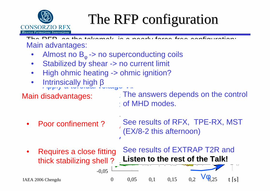
The RFP configurationThe RFP configurationThe RFP, as the tokamak, is a nearly force-free configuration: the current density J is ∼ // to B
The recepee: • Apply a small toroidal field Bφ (50 mT OK)• Apply a toroidal voltage Vφ• Wait (some ms) for plasma self-organizationHere is Your RFP plasma:
-0,05
0,00
0,05
0,10
0,15
0,20
0,25
0,30
0 0,05 0,1 0,15 0,2 0,25 0,3
-0,100,10,20,30,40,50,60,7
Bφ (a)
<Bφ>
Bθ(a) & I 18500
[T] [MA]
t [s]
force-free magnetic field : µ0J = ∇×B = µB
Main advantages: • Almost no Bφ -> no superconducting coils• Stabilized by shear -> no current limit• High ohmic heating -> ohmic ignition?• Intrinsically high β
Main disadvantages:
• Poor confinement ?
• Requires a close fitting thick stabilizing shell ?
B &J field lines
Vφ
The answers depends on the control of MHD modes.
See results of RFX, TPE-RX, MST (EX/8-2 this afternoon)
See results of EXTRAP T2R andLListenisten to the rest of the Talk!to the rest of the Talk!

IAEA 2006 Chengdu
MHD Mode Classification in RFPsMHD Mode Classification in RFPs
q (r) Internally non-resonant
Resistive Wall Modesm=1, n=-7
m=1, n=-8m=1, n=-9
““ DYNAMO MODES”DYNAMO MODES”
•• provide Jprovide Jθθθθθθθθ at reversal at reversal
radiusradius
•• Magnetic Magnetic
Stochasticity in coreStochasticity in core
•• NonNon--AxisymmetricAxisymmetric
perturbation LMperturbation LM
Externally non-resonant Resistive Wall Modes
m=1, n > 0
m=1, n =-5
m=1, n =-6
m=0, all n
internally internally resonating resonating tearing tearing modes modes
r (m)
IAEA 2006 Chengdu
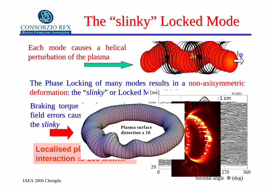
The Phase Locking of many modes results in a The Phase Locking of many modes results in a nonnon--axisymmetric axisymmetric deformationdeformation: the “: the “slinkyslinky” or ” or Locked Mode (LM)Locked Mode (LM)
The “slinky” Locked ModeThe “slinky” Locked Mode
Each mode causes a helical Each mode causes a helical perturbation of the plasmaperturbation of the plasma IφJn
80
40
200 90 180 270 360
t [ms]
toroidal angle Φ (deg)
#12461
60
1001 cm
Braking torque by the vessel and Braking torque by the vessel and field errors cause field errors cause Wall LockingWall Locking of of the the slinkyslinky
Localised plasma-wall interaction ⇒⇒⇒⇒ 100 MW/m2
Plasma surface distortion x 10
IAEA 2006 Chengdu
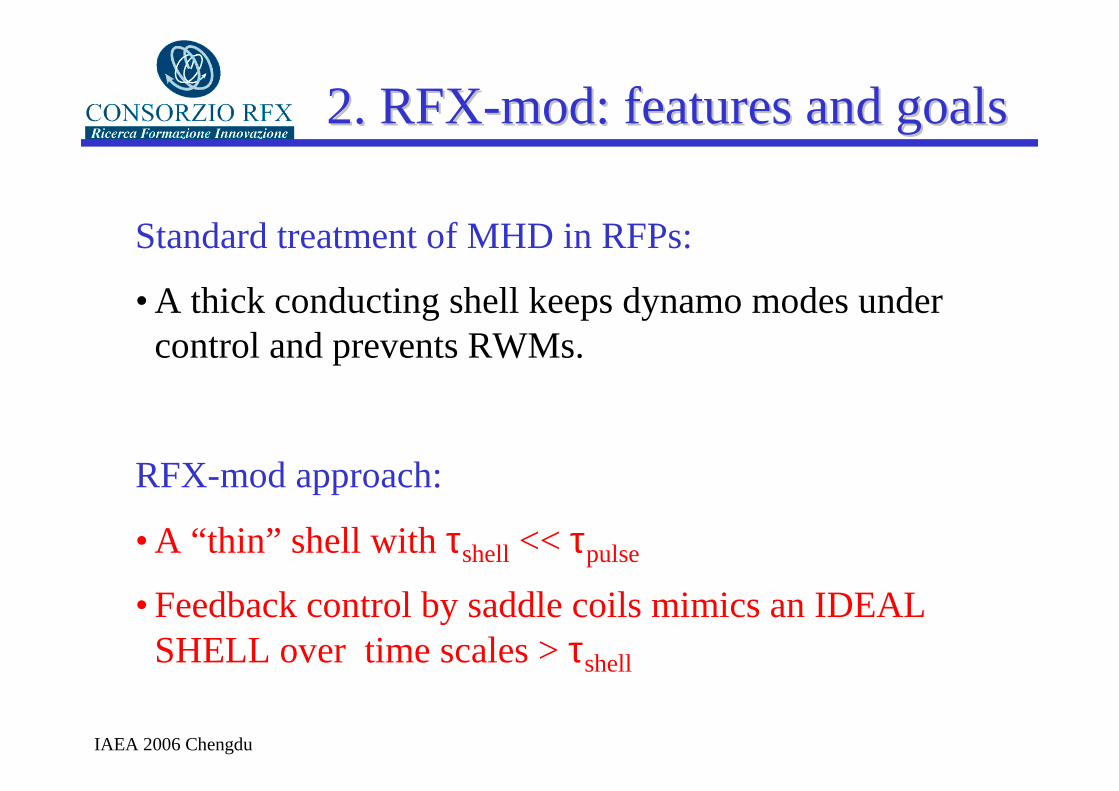
2. RFX2. RFX--mod: features and goalsmod: features and goals
Standard treatment of MHD in RFPs:
• A thick conducting shell keeps dynamo modes under control and prevents RWMs.
RFX-mod approach:
• A “thin” shell with τshell << τpulse
• Feedback control by saddle coils mimics an IDEAL SHELL over time scales > τshell

IAEA 2006 Chengdu
τshell =0.05 s (RFX 0.450s)
b/a = 1.1 (RFX 1.24)
RFX-mod new features
• Thinner and more closely fitting shell
• Improved design graphite tile first wall armour
• New Bϕ power supplies
• 192 active saddle coils
• Digital feedback system for MHD modes and main coil circuits
Lower power on leading edges
Better dynamo mode control
Highly flexible control of field errors, Dynamo modes and Resistive Wall Modes
Goal of the modifications:
Demonstrate the operation of the largest existing RFP
• without a thick shell
• in the MA range
• with real-time control of:
- Equilibrium
- MHD modes (tearing and RWM)

IAEA 2006 Chengdu
The MHD control system
Saddle coil layout: Full Poloidal and Toroidal coverage
192 coils: 4 poloidal x 48 toroidal
Wide spectrum of Fourier components :Wide spectrum of Fourier components :
(Dictated by Dynamo modes)
• m=0,1,2 (partial)
• n ≤ 24
Frequency response:Frequency response:
• DC < f < 1 kHz
Digital feedback control system:
Allows a variety of schemes for selective control of modes
See paper by Luchetta A., et al., FT/P5-1
IAEA 2006 Chengdu
Many control schemes are possibleMany control schemes are possible
�Intelligent shell (local radial field compensation)
�Selective Virtual Shell (cancels all harmonics but some, e.g. m=1, n=0 equilibrium field)
�Virtual Shell + rotating perturbations (phase and amplitude of selected harmonics set to follow given waveforms)
�Mode Control (regulators applied to modes rather than to single coils)

IAEA 2006 Chengdu
3.Comparison RFX 3.Comparison RFX // RFXRFX--mod mod
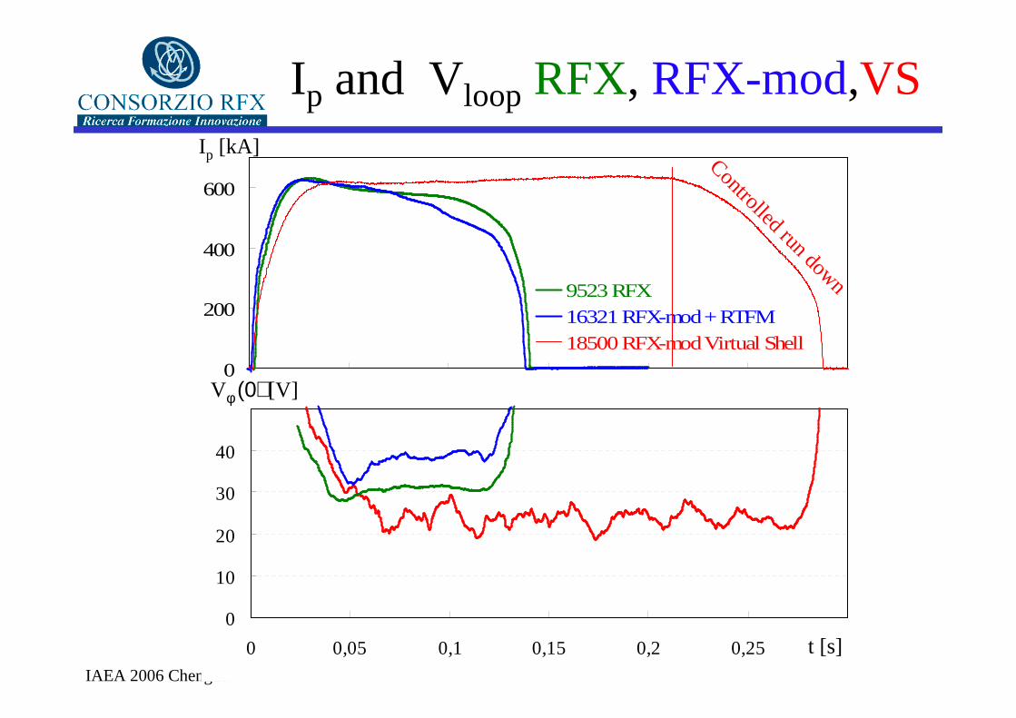
Benchmark pulses at 600 kA:
• RFX
• RFX-mod “passive” shell
• RFX-mod Virtual Shell
IAEA 2006 Chengdu
Ip and Vloop RFX, RFX-mod,VS
0
10
20
30
40
50
0 0,05 0,1 0,15 0,2 0,25 0,3t [s]
Ip [kA]
0
200
400
600
0 0,05 0,1 0,15 0,2 0,25 0,3
9523 RFX16321 RFX-mod + RTFM18500 RFX-mod Virtual Shell
Vφ (0) [V]
Controlled run down
IAEA 2006 Chengdu
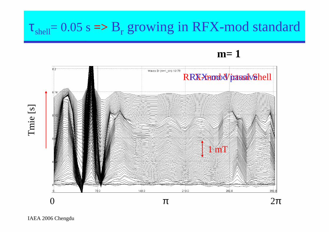
Br(a) reduced below 0.5 mT with VS
m= 1
Tm
ie[s
]
0 π 2π
τshell= 0.05 s => Br growing in RFX-mod standard
1 mT
RFX-mod Virtual ShellRFX-mod passive

IAEA 2006 Chengdu
LM is quenched by Virtual ShellLM is quenched by Virtual Shell
Plasma perturbation due to LM with Virtual Shell and Without: • m=1 is < 1 cm • m=0 is ∼ 1.5 cm
m=1m=1 m=0m=0
m=1 (cm)
m=0 (cm)
Φ (deg)-3
-2
-1
0
1
2
3
4
5
0 90 180 270
17262 RFX-mod18645 RFX-mod VS
-3
-2
-1
0
1
2
3
4
5
0 90 180 270
17262 RFX-mod18645 RFX-mod VS
IAEA 2006 Chengdu
What happens in plasma What happens in plasma core?core?
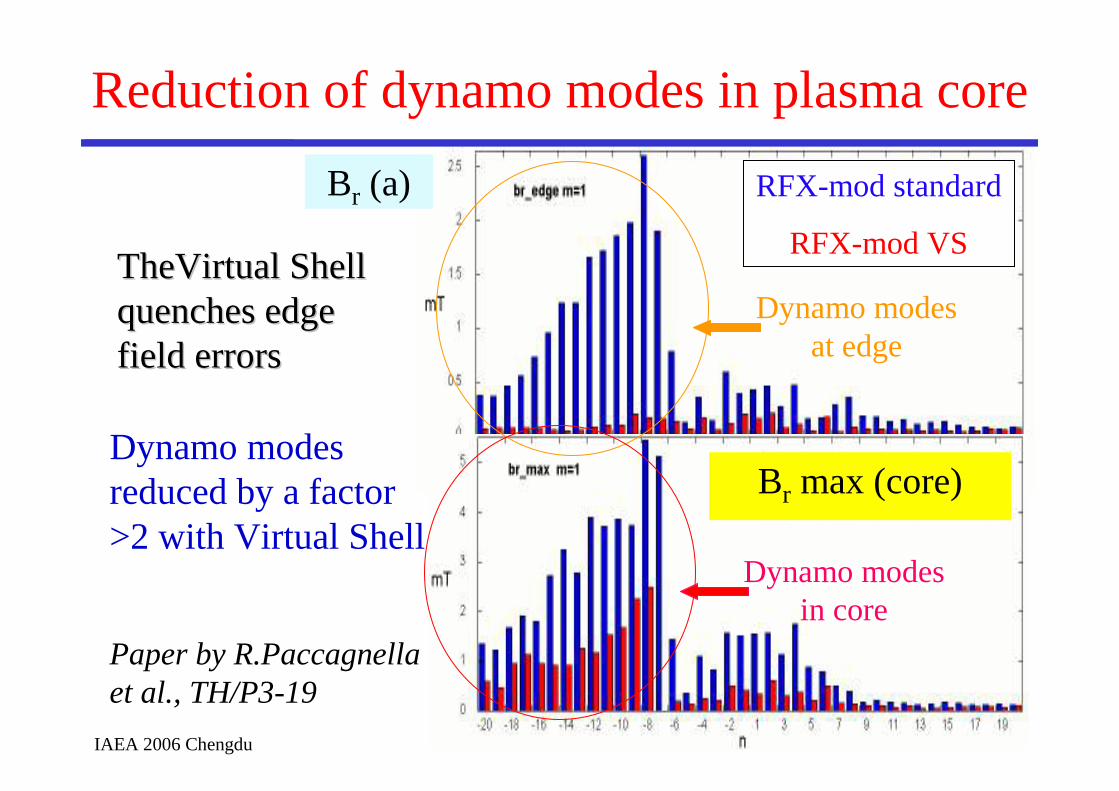
TheVirtual Shell TheVirtual Shell quenches edge quenches edge field errorsfield errors
Reduction of dynamo modes in plasma core
RFX-mod standard
RFX-mod VS
Br (a)
Br max (core)
Dynamo modes at edge
Dynamo modes reduced by a factor >2 with Virtual Shell
Paper by R.Paccagnella et al., TH/P3-19
Dynamo modes in core

IAEA 2006 Chengdu
Electron Temperature profiles and χ
r [m]
χe [m2s]
r [m]
Virtual Shell
standard
#17453 : ττττE~ 1.5 ms
IAEA 2006 Chengdu
4. Feedback Control of Resistive Wall Modes
IAEA 2006 Chengdu
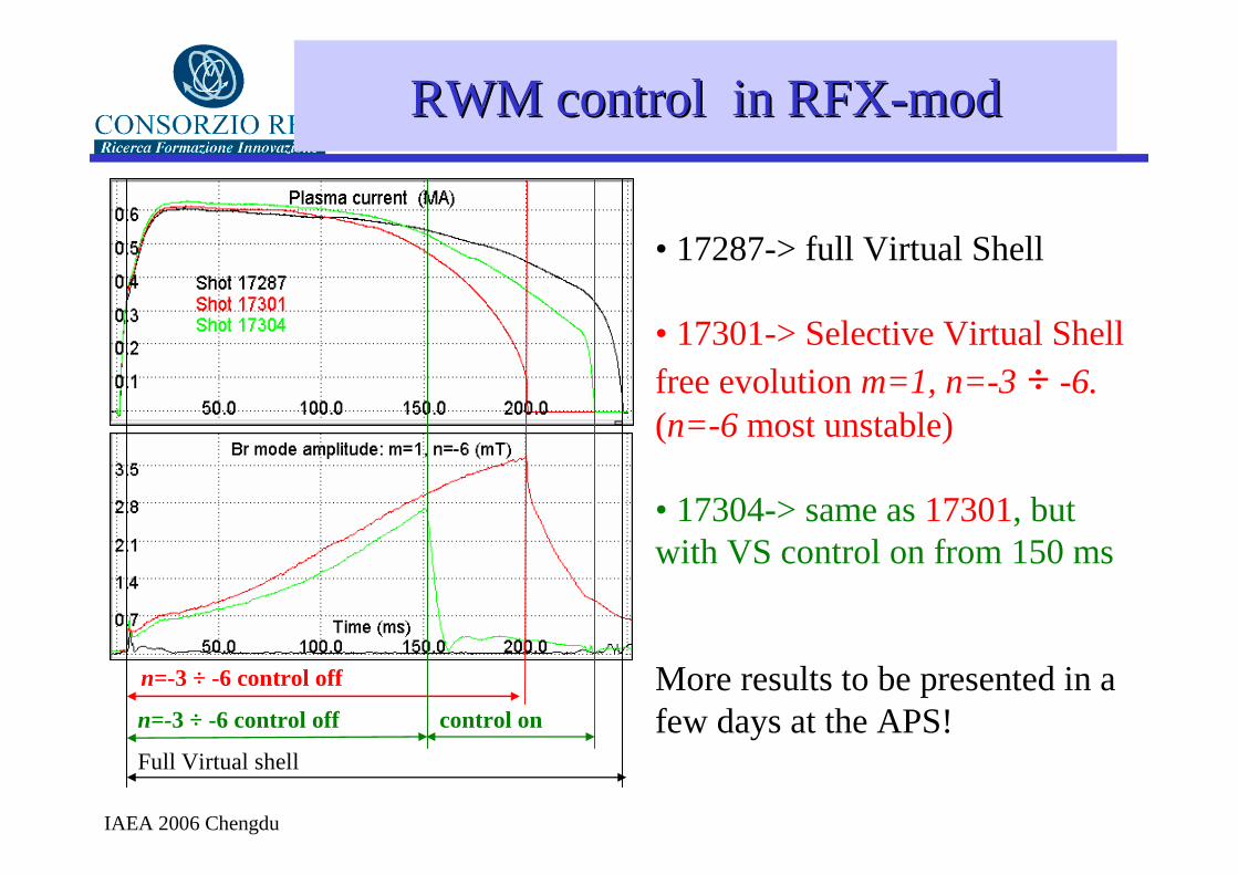
RWM RWM controlcontrol in in RFXRFX--modmod
• 17287-> full Virtual Shell
• 17301-> Selective Virtual Shell free evolutionm=1, n=-3 ÷ -6.(n=-6 most unstable)
• 17304-> same as 17301, but with VS control on from 150 ms
More results to be presented in a few days at the APS!
Full Virtual shell
n=-3 ÷ -6 control off
n=-3 ÷ -6 control off control on
IAEA 2006 Chengdu
5. Mode rotation /Confinement @ 1 MAMode rotation /Confinement @ 1 MA
High current pulses:
• Locked Mode Rotation
• 1 MA discharges

IAEA 2006 Chengdu
LM rotation by RTFMLM rotation by RTFM
external m=0 mode
n-1, m=1 mode goes backward
n+2, m=1 has doubled frequency (harmonic generation)
most restrained m=1 is stationary
n+1, m=1 mode goes forward
harmonic generation
φ0ext
φ1,7LM
φ1,8LM
φ1,9LM
φ1,10LM
φ1,11LM
0
0
90
180
270
0
90
180
270
0
90
180
270
20 40 60 80 100
Time (ms)
# 1
23
50
0
90
180
270
0
90
180
270
0
90
180
270
360
0
0
0
90
180
270
0
90
180
270
0
90
180
270
20 40 60 80 100
Time (ms)
# 1
23
50
0
90
180
270
0
90
180
270
0
90
180
270
360
0
t (ms)
80
40
20
0 90 180 270 360
t [ms]
toroidal angle Φ (deg)
#12350
60
1 cm0
Result: continuous LM rotation for the whole discharge
Bartiromo R., et al., PRL83 (1999)1779.
Rotating Toroidal Field Modulation: a rotating m= 0 perturbation is applied by the 12 sectors of the Bφ coils
IAEA 2006 Chengdu
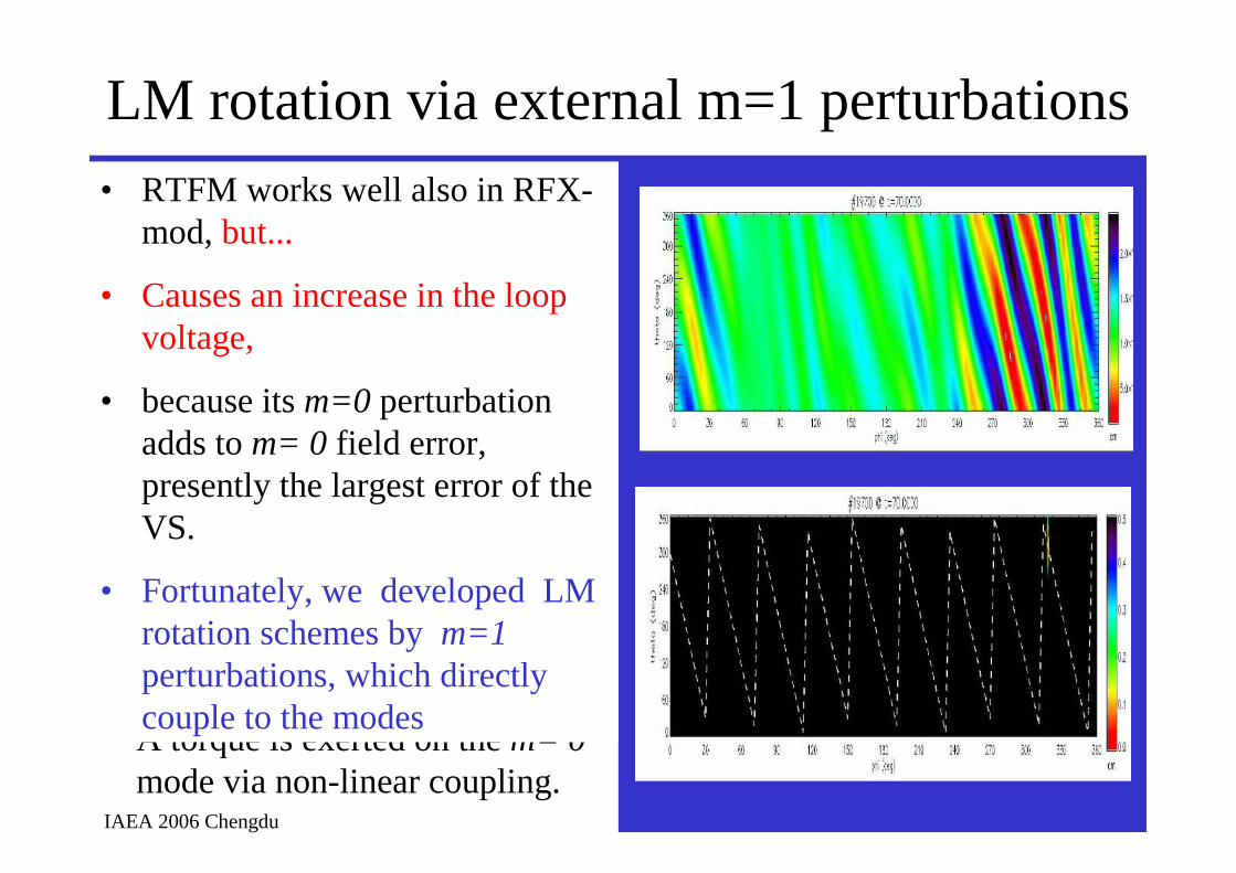
LM rotation via external m=1 perturbations
Several rotating m=1perturbations are generated at frequency equispaced with n:
• 1,-8 @ -10 Hz
• 1,-10 @ 10 Hz
• 1,-11 @ 20 Hz
• 1,-12 @ 30 Hz
This scheme rotates the LM pattern along the stationary 1,-9mode.
A torque is exerted on the m= 0mode via non-linear coupling.
• RTFM works well also in RFX-mod, but...
• Causes an increase in the loop voltage,
• because its m=0 perturbation adds to m= 0 field error, presently the largest error of the VS.
• Fortunately, we developed LM rotation schemes by m=1perturbations, which directly couple to the modes

IAEA 2006 Chengdu
Well Controlled 1MA pulses with LM rotationWell Controlled 1MA pulses with LM rotation
0200400600800
10001200
0 0,1 0,2 0,3 0,4
0
10
20
30
40
50
0 0,1 0,2 0,3 0,4
0
1
2
3
4
0 0,1 0,2 0,3 0,4
0100200300400500600
0 0,1 0,2 0,3 0,4
-1200
-700
-200
300
800
0 0,1 0,2 0,3 0,4
1967619669196781969919700197011970219761φ L
M (
deg)
Τ e
(eV
)n e
·101
9(m
-3)
Vφ(V
)Ι p
(kA
)
Start of controlled run down
a
b
c
d
e
t (s)
0
50
100
150
200
250
300
350
400
450
500
-0,5 -0,4 -0,3 -0,2 -0,1 0,0 0,1 0,2 0,3 0,4 0,5
Te (eV)
r (m)
LM rotation with Virtual Shell + rotating m = 1 perturbation
achieves very reliable LM rotation
This results in long and This results in long and reproducible 1MA pulsesreproducible 1MA pulses
Where density control is not Where density control is not lost from pulse to pulselost from pulse to pulse
And current, density and And current, density and temperature can be temperature can be
“superimposed”“superimposed”
temperature profiles are temperature profiles are broad and very similar toobroad and very similar too
IAEA 2006 Chengdu
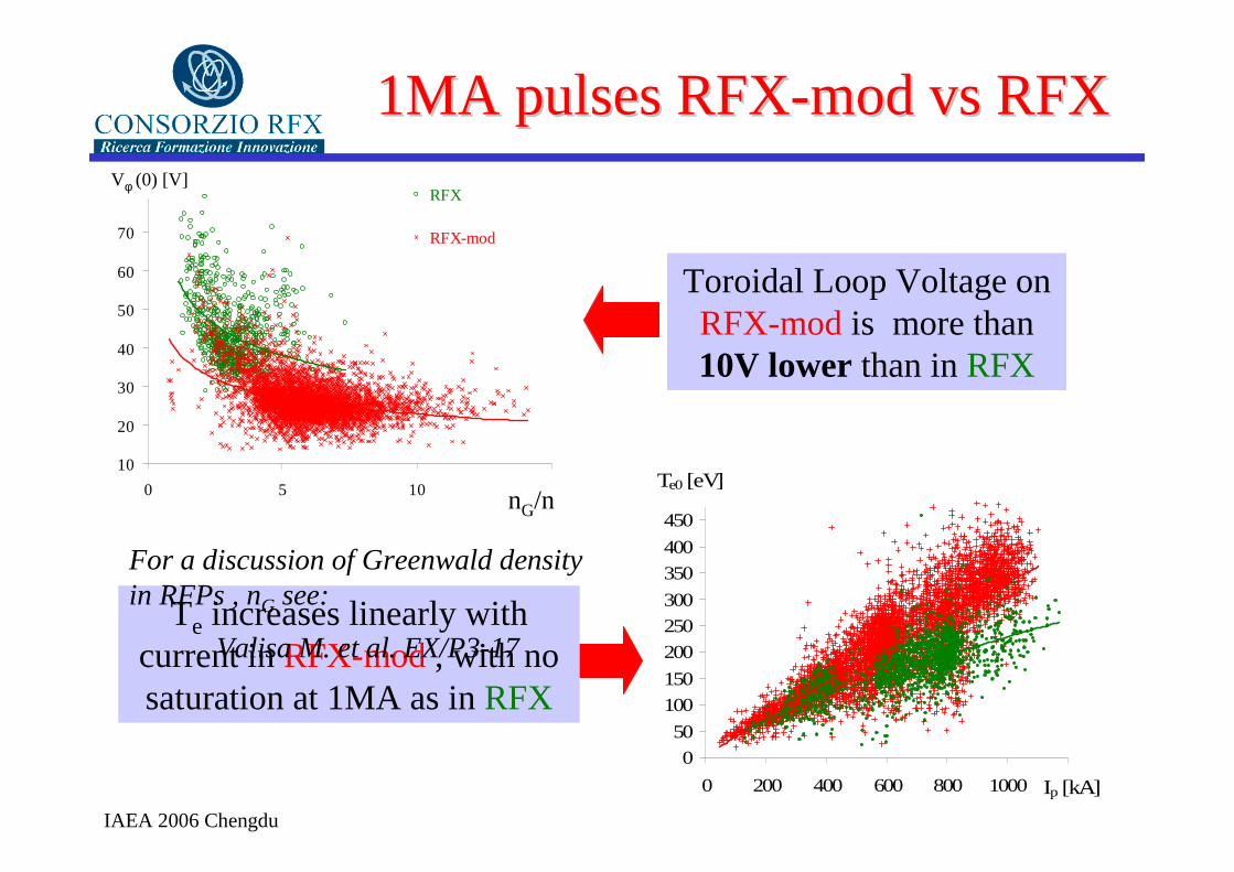
1MA pulses RFX1MA pulses RFX--mod vs RFXmod vs RFX
10
20
30
40
50
60
70
80
0 5 10 15
RFX
RFX-mod
Power (RFX)
Power (RFX-mod)
Vφ (0) [V]
I/N·10-14 (Am)
10
20
30
40
50
60
70
80
0 5 10 15
RFX
RFX-mod
Power (RFX)
Power (RFX-mod)
Vφ (0) [V]
I/N·10-14 (Am)
0
50
100
150
200
250
300
350
400
450
500
0 200 400 600 800 1000 1200Ip [kA]
Te0 [eV]
Toroidal Loop Voltage on RFX-mod is more than 10V lower than in RFX
Te increases linearly with current in RFX-mod , with no saturation at 1MA as in RFX
nG/n
For a discussion of Greenwald density in RFPs , nG see:
Valisa M. et al. EX/P3-17

IAEA 2006 Chengdu
Energy confinement in RFXEnergy confinement in RFX--modmod
0
0.5
1
1.5
0 0.5 1 1.5
RFX-mod VSRFX-mod NVS
ττ ττ E (
ms)
1.1 10-13 I 1.17 (I/N)-0.35 b8-15
-0.61 (A*Am*T)
• Energy confinement time has a clear scaling with plasma current
• Also the dependence on field error amplitude is very encouraging
more in Innocente P. et al., Paper EX/P3-10
IAEA 2006 Chengdu
6. Advanced RFP scenarios
• Quasi Single Helicity States
• Oscillating Poloidal Current Drive

IAEA 2006 Chengdu
Long lasting QSH in Virtual Shell dischargesLong lasting QSH in Virtual Shell discharges
SXR1/SXR2
long lasting QSH are more likely long lasting QSH are more likely -- at high current andat high current and-- shallow reversal (F shallow reversal (F ~ ~ --0.1)0.1)
Island
a hot helical core is presenta hot helical core is presentfor time periods >for time periods >ττττττττEE
Shafranovshift
SXR1SXR2
Mode m=1 n=Mode m=1 n=--77 (innermost (innermost resonating) grows much larger resonating) grows much larger than the than the other dynamo modesother dynamo modes
Quasi Single Helicty states Quasi Single Helicty states were discovered on RFXwere discovered on RFXESCANDE D. F., et al. Phys. ESCANDE D. F., et al. Phys. Rev. Rev. LettLett. 85 (2000) 1662. 85 (2000) 1662
IAEA 2006 Chengdu
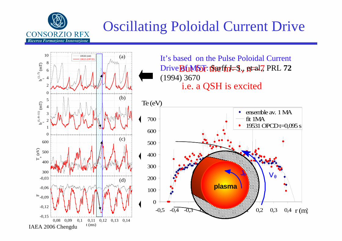
Oscillating Poloidal Current Drive
0
2
4
6
8
10 19530 (std)
19615 (OPCD)
b t(1,-
7) (
mT
)
(a)
0
1
2
3
4
5
b t(1,-
8--1
1) (
mT
)
(b)
300
400
500
600
Te (
eV)
(c)
-0,15
-0,12
-0,09
-0,06
-0,03
0,08 0,09 0,1 0,11 0,12 0,13 0,14
F
t (ms)
(d)
BLACK is a standard VS pulse
RED is a VS +OPCD pulse
An Oscillating Poloidal Voltage is applied to the plasma by the
the Toroidal Field Coils
during each Toroidal Field Reversal enhancement fase
The MHD Dynamo modes are suppressed
But for the m=1, n=-7
i.e. a QSH is excited
Which reflects in a higher core Te
0
100
200
300
400
500
600
700
800
-0,5 -0,4 -0,3 -0,2 -0,1 0,0 0,1 0,2 0,3 0,4 0,5
ensemble av. 1 MAfit 1MA19531 OPCD t=0,095 s
Te (eV)
r (m)
plasma
VθJθ
plasma
VθJθ
It’s based on the Pulse Poloidal Current Drive of MST: Sarff J. S., et al., PRL 72(1994) 3670
IAEA 2006 Chengdu
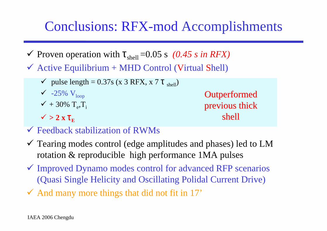
Conclusions: RFX-modAccomplishments
� Proven operation with τshell =0.05 s (0.45 s in RFX)
� Active Equilibrium + MHD Control (Virtual Shell)
� pulse length = 0.37s (x 3 RFX, x 7 τ shell)
� -25% Vloop
� + 30% Te,Ti
� > 2 x ττττE
� Feedback stabilization of RWMs
� Tearing modes control (edge amplitudes and phases) led to LM rotation & reproducible high performance 1MA pulses
� Improved Dynamo modes control for advanced RFP scenarios (Quasi Single Helicity and Oscillating Polidal Current Drive)
� And many more things that did not fit in 17’
Outperformed Outperformed previous thick previous thick
shellshell
IAEA 2006 Chengdu
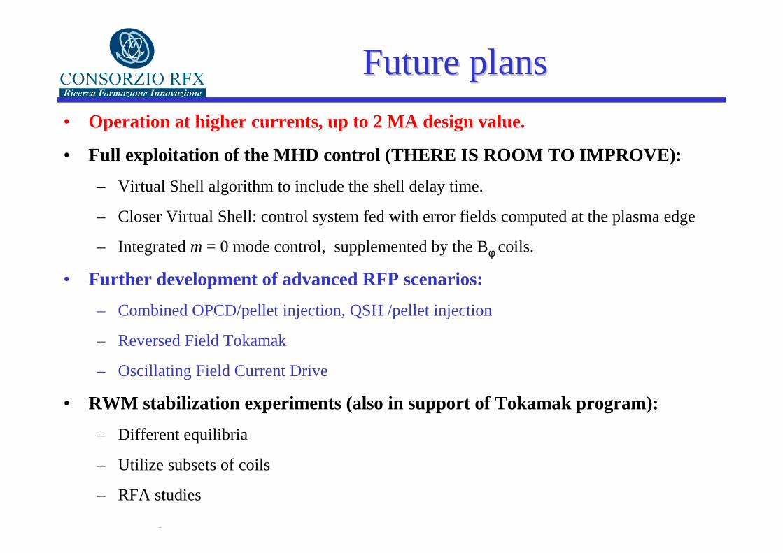
Future plansFuture plans
• Operation at higher currents, up to 2 MA design value.
• Full exploitation of the MHD control (THERE IS ROOM T O IMPROVE):
– Virtual Shell algorithm to include the shell delay time.
– Closer Virtual Shell: control system fed with error fields computed at the plasma edge
– Integratedm = 0 mode control, supplemented by the Bφ coils.
• Further development of advanced RFP scenarios:
– Combined OPCD/pellet injection, QSH /pellet injection
– Reversed Field Tokamak
– Oscillating Field Current Drive
• RWM stabilization experiments (also in support of Tokamak program):
– Different equilibria
– Utilize subsets of coils
– RFA studies

IAEA 2006 Chengdu
RFXRFX--modmod
12 toroidal coils sectors with independent power supplies
Closed shell equatorial gapvacuum vessel with
improved graphite tiles 3 mm Cu shell
192 active saddle coils for MHD
control
R 2 m
a 0.46 m
I 0.3-1.1 (2) MA
τpulse 0.37 s
τshell 0.05 s
• A flexible device to study confinement at high current and in advanced scenarios for the RFP
• A powerful tool for MHD studies in support of the other programs
IAEA 2006 Chengdu
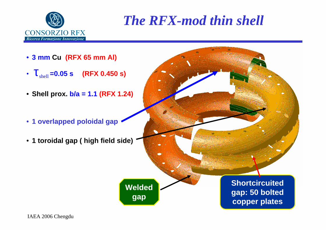
The RFX-mod thin shell
Shortcircuitedgap: 50 bolted copper plates
• 3 mm Cu (RFX 65 mm Al)
Welded gap
• 1 overlapped poloidal gap
• 1 toroidal gap ( high field side)
• τshell =0.05 s (RFX 0.450 s)
• Shell prox. b/a = 1.1 (RFX 1.24)

IAEA 2006 Chengdu
First wall• Optimized tile shape:
– Tapered poloidal shape
– Thickness reduced to 17 mm (a = 0.459 m)
– Reduced poloidal / toroidal gaps between adjacent tiles to < 3 mm
• Factor ≈ 2 reduction of Pwmax

IAEA 2006 Chengdu
RFX-mod: MHD Control System
latency time: 330 µsm modes: 0, 1, -1, 2 (partial)n modes: 0-23
IAEA 2006 Chengdu
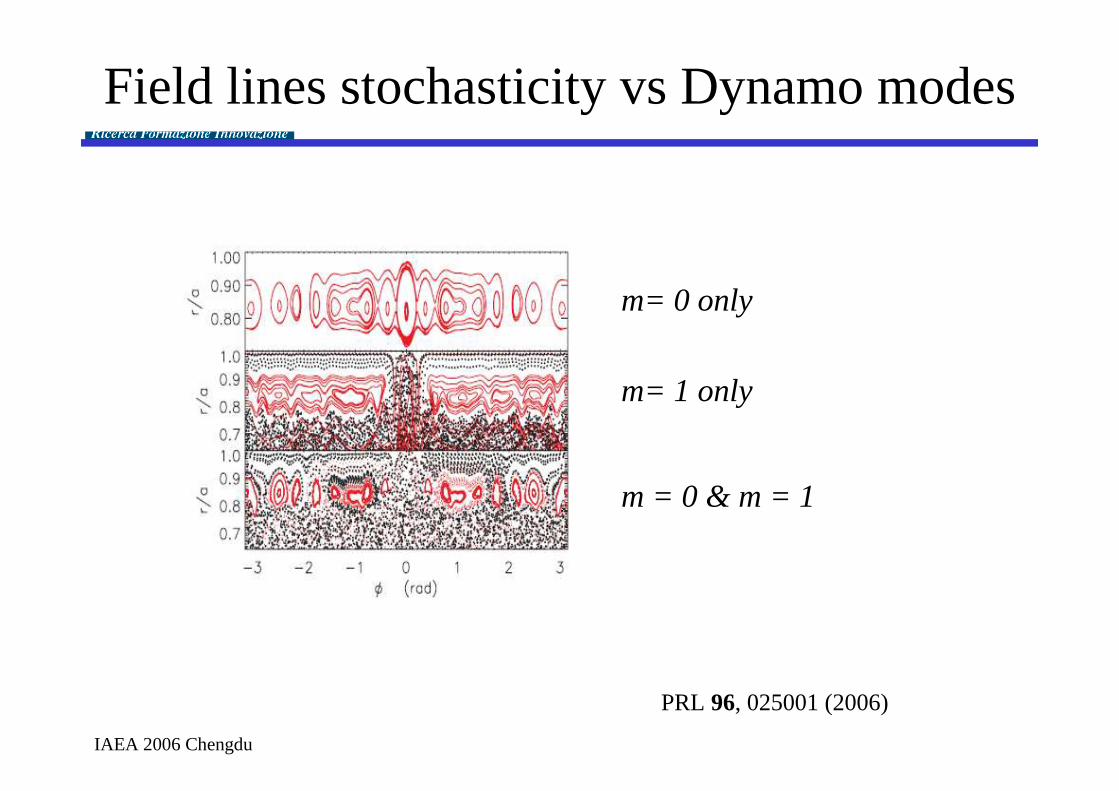
Field lines stochasticity vs Dynamo modes
m= 0 only
m= 1 only
m = 0 & m = 1
PRL 96, 025001 (2006)
IAEA 2006 Chengdu

IAEA 2006 Chengdu
0
200
400
600
800
1000
1200
0 0,1 0,2 0,3 0,4
0
200
400
600
800
1000
1200
0 0,1 0,2 0,3 0,4
0
200
400
600
800
1000
1200
0 0,1 0,2 0,3 0,4
0
200
400
600
800
1000
1200
0 0,1 0,2 0,3 0,4
0
200
400
600
800
1000
1200
0 0,1 0,2 0,3 0,4
0
200
400
600
800
1000
1200
0 0,1 0,2 0,3 0,4
0
200
400
600
800
1000
1200
0 0,1 0,2 0,3 0,4
0
200
400
600
800
1000
1200
0 0,1 0,2 0,3 0,4
Well Controlled 1MA pulses with LM rotationWell Controlled 1MA pulses with LM rotation
Ip [kA]
IAEA 2006 Chengdu
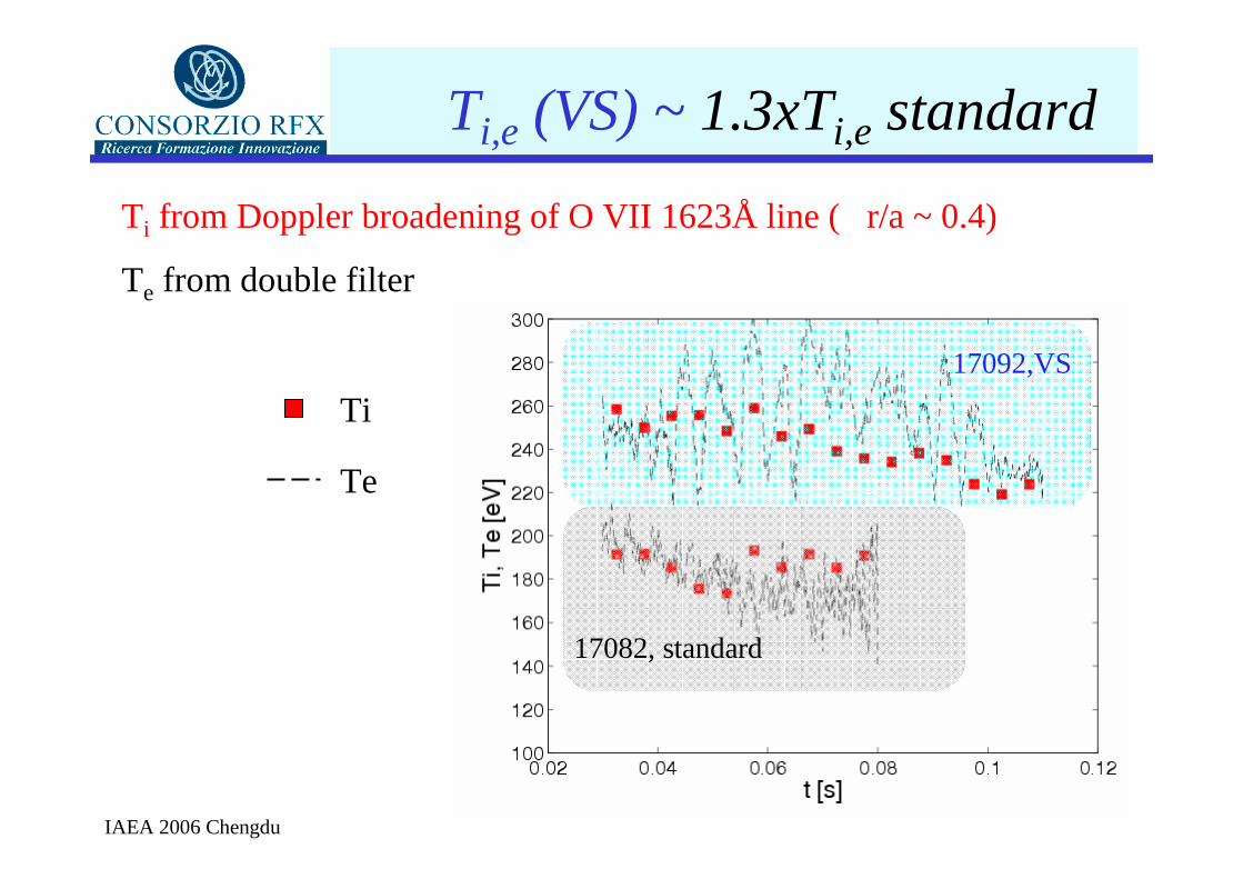
Ti from Doppler broadening of O VII 1623Å line ( r/a ~ 0.4)
Te from double filter
Ti,e (VS) ~ 1.3xTi,e standard
Ti
Te
17082, standard
17092,VS

IAEA 2006 Chengdu
Rotating Toroidal Field ModulationRotating Toroidal Field Modulation
t [s]
Current in the sectors
A rotating m=0 perturbation by the 12 Bφ coil sectors exerts a torque on the q=0 island:
Tz0,1 ∝ br
0,1Br0,1(r,1)sin(∆φ0,1)
Tviscm ,n ∝ (br
m,n ) 2 ωRotation is opposed by drag of eddy currents in vessel
A sufficiently high external Br0,1 overcomes the drag and lock
in phase the 0,1 mode
1
23
6
45
1
23
6
45
1
23
6
45
IAEA 2006 Chengdu
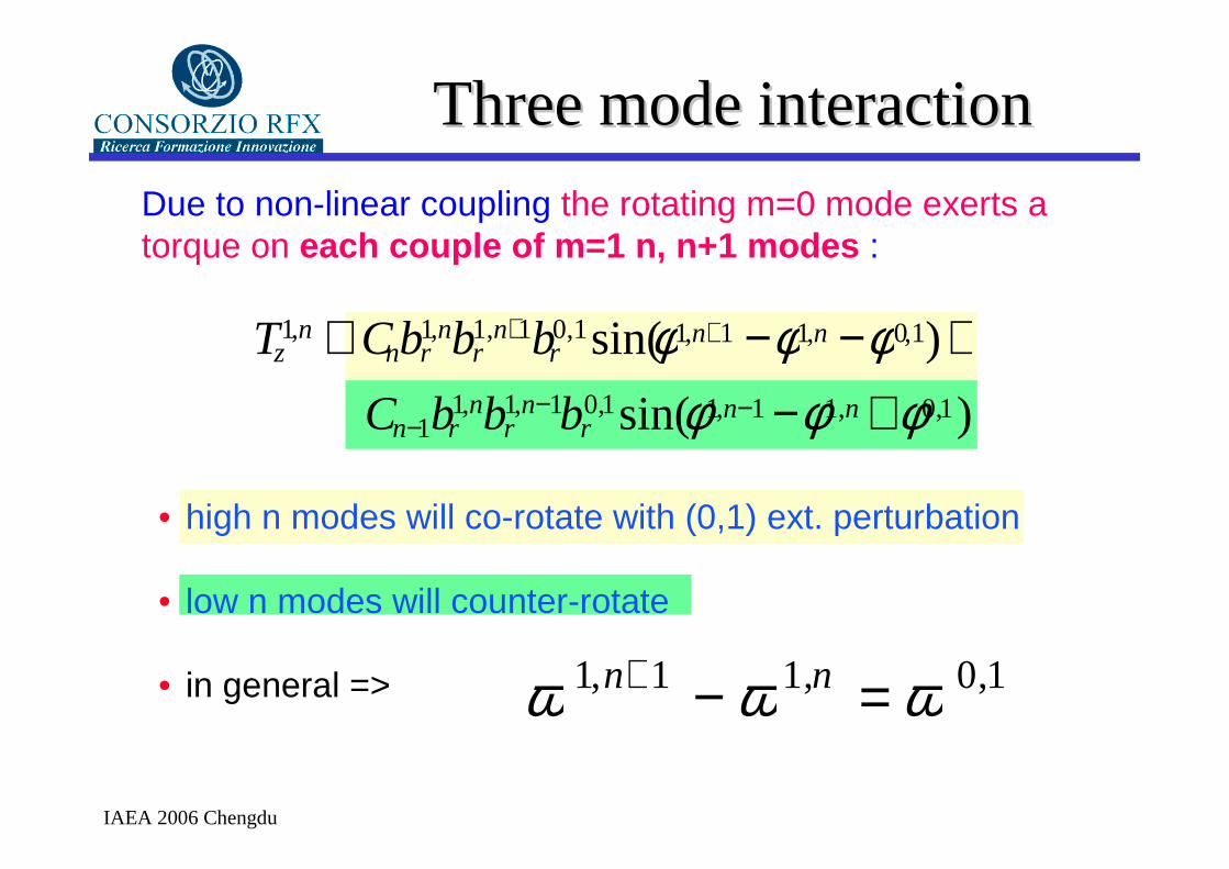
Three mode interactionThree mode interaction
ω 1,n+1 − ω 1,n = ω 0,1
• high n modes will co-rotate with (0,1) ext. perturbation
• low n modes will counter-rotate
• in general =>
Tz1,n ∝Cnbr
1,nbr1,n+1br
0,1sin(φ1,n+1 −φ1,n −φ0,1)+ Cn−1br
1,nbr1,n−1br
0,1sin(φ1,n−1 −φ1,n +φ0,1)
Due to non-linear coupling the rotating m=0 mode exerts a torque on each couple of m=1 n, n+1 modes :
IAEA 2006 Chengdu
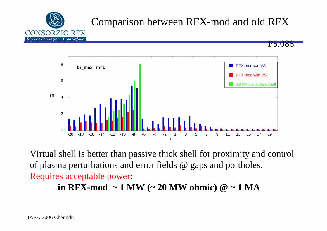
Comparison between RFX-mod and old RFX
Virtual shell is better than passive thick shell for proximity and control of plasma perturbations and error fields @ gaps and portholes.Requires acceptable power:
in RFX-mod ~ 1 MW (~ 20 MW ohmic) @ ~ 1 MA
P5.088
0
2
4
6
8
-20 -18 -16 -14 -12 -10 -8 -6 -4 -2 1 3 5 7 9 11 13 15 17 19
br_max m=1 RFX-mod w/o VS
RFX-mod with VS
old RFX with thick shell
mT
n

IAEA 2006 Chengdu
B &J field lines
Vφ
The RFP configurationThe RFP configurationforce-free magnetic field: µ0J = ∇×B = µB
0
0.2
0.4
0.6
0.8
1
0 0.2 0.4 0.6 0.8 1
Jθ
Jφ
r/a
0
0.2
0.4
0.6
0.8
1
Bθ
Bφ
A ‘dynamo’ mechanism A ‘dynamo’ mechanism drives Jdrives Jθθ at the Bat the Bφφ reversal reversal surfacesurface
IAEA 2006 Chengdu
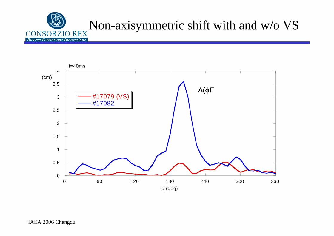
0
0,5
1
1,5
2
2,5
3
3,5
4
0 60 120 180 240 300 360
∆(ϕ)∆(ϕ)∆(ϕ)∆(ϕ)#17079 (VS)#17082
(cm)
ϕ (deg)
t=40ms
Non-axisymmetric shift with and w/o VS

IAEA 2006 Chengdu
The RFP DynamoThe RFP DynamoB &J field lines
Vφ
A ‘dynamo’ mechanism A ‘dynamo’ mechanism drives Jdrives Jθθ at the Bat the Bφφ reversal reversal surface and beyondsurface and beyond
This can be otained only by breaking the toroidal This can be otained only by breaking the toroidal symmetry (Cowling theorem).symmetry (Cowling theorem).
Here is where the RFP “dynamo” modes come into play...Here is where the RFP “dynamo” modes come into play...

IAEA 2006 Chengdu
Plasma wall interaction with new wall
•The penetration of the mode radial field component through the thin shell is fast, which leads to enhanced plasma wall interaction.
•Improved graphite tiles design counters this effect by spreading the power deposition over the tile center rather than on edges.
•This is confirmed by CCD images of plasma-wall interaction taken during pulses.
•Periodic in-vessel inspection showed that, contrary to the past, after several hundred pulses no damage has been done to the tile edges.