OVERVIEW OF RECENT TRENDS AND … · May 16, 2011 –DIPAC 2011 M ... Libera Crossbar Switch CAL...
31
OVERVIEW OF RECENT TRENDS AND DEVELOPMENTS FOR BPM SYSTEMS Manfred Wendt Fermilab Assembled with great help of the colleagues from the beam instrumentation community!
Transcript of OVERVIEW OF RECENT TRENDS AND … · May 16, 2011 –DIPAC 2011 M ... Libera Crossbar Switch CAL...
OVERVIEW OF RECENT TRENDS
AND DEVELOPMENTS
FOR BPM SYSTEMS
Manfred Wendt
Fermilab
Assembled with great help of the colleagues from the beam instrumentation community!
Page 2 May 16, 2011 – DIPAC 2011 – M. Wendt
Contents
• Introduction
• BPM Pickup
– Broadband BPM Pickups
Examples
– Resonant BPM Pickups
Examples
• Read-out Electronics
Examples
• Summary

Page 3 May 16, 2011 – DIPAC 2011 – M. Wendt
Introduction: Beam Trajectory
• Primary task: A BPM system measures the beam trajectory
– the horizontal / vertical beam position.
– Measurement of x, y at discrete locations s
– Measurement of the beam angle x’, y’ between two BPMs
…if non optical elements are present.
beam
trajectory
Focusing elements
(e.g. quadrupoles)
BPM Pickups
s
x, y
ds
v
𝑢 𝑠 = 𝐴 𝛽 sin 𝑄𝜑 + 𝛿
𝑢 = (𝑥, 𝑦)

Page 4 May 16, 2011 – DIPAC 2011 – M. Wendt
BPM Building Blocks
• BPM pickup
– RF device, EM field detection,
center of charge
– Symmetrically arranged electrodes,
or resonant structure
• Read-out electronics
– Analog signal conditioning
– Signal sampling (ADC)
– Digital signal processing
Analog Signal
Conditioning
Digital Signal Processing
Data Acquisition
Trigger, Timing & RF
Control
Power Supply &
Misc.
BPM Pickup
position
data
control
system
(LAN)
timing,
RF & CLK
signals
feedback bus
(if applicable)
– Data acquisition and control
system interface
– Trigger, CLK & timing signals
Page 5 May 16, 2011 – DIPAC 2011 – M. Wendt
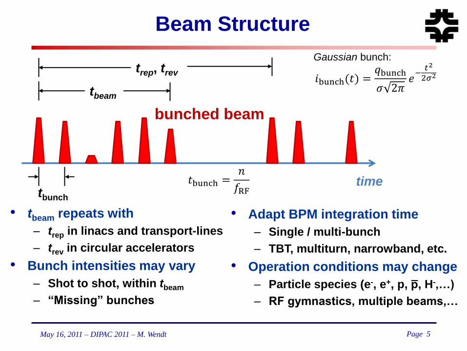
Beam Structure
• tbeam repeats with
– trep in linacs and transport-lines
– trev in circular accelerators
• Bunch intensities may vary
– Shot to shot, within tbeam
– “Missing” bunches
tbunch
trep, trev
time
bunched beam
tbeam
𝑡bunch =𝑛
𝑓RF
• Adapt BPM integration time
– Single / multi-bunch
– TBT, multiturn, narrowband, etc.
• Operation conditions may change
– Particle species (e-, e+, p, p̅, H-,…)
– RF gymnastics, multiple beams,…
𝑖bunch(𝑡) =𝑞bunch
𝜍 2𝜋𝑒−𝑡2
2𝜎2
Gaussian bunch:

Page 6 May 16, 2011 – DIPAC 2011 – M. Wendt
BPM Characteristics & Applications
• Measurement / integration time
• Position resolution
– Resolve a orbit difference (depends on the measurement time).
• Linearity and accuracy
– Absolute error of the reported beam position
– BPM offset (zero-order correction coefficient), BPM tilt
• x-y coupling
• Dynamic range
– Beam intensity independence (saturation / noise floor).
• Reproducibility and long term stability
– Reference “golden” orbit
• Variety of applications beyond beam orbit measurements
– Injection oscillations, betatron & synchrotron tunes, dispersion
& beam energy, x-y coupling, beam optics, magnet alignment
and errors, non-linear field effects, etc.
– Machine commissioning (intensity), beam phase and TOF

Page 7 May 16, 2011 – DIPAC 2011 – M. Wendt
BPM Offset & Tilt
BPM Read-out (electr. offset)
x
y
BPM
offset
quad
offset
beam
position
reported
beam
position
• BPM – quad alignment
– Mechanical & “electrical” offsets
– BBA procedure
• Same for BPM / quad tilt
Page 8 May 16, 2011 – DIPAC 2011 – M. Wendt
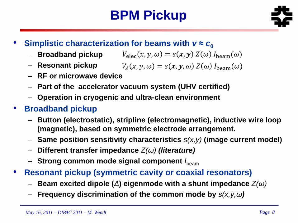
BPM Pickup
• Simplistic characterization for beams with v ≈ c0
– Broadband pickup
– Resonant pickup
– RF or microwave device
– Part of the accelerator vacuum system (UHV certified)
– Operation in cryogenic and ultra-clean environment
• Broadband pickup
– Button (electrostatic), stripline (electromagnetic), inductive wire loop
(magnetic), based on symmetric electrode arrangement.
– Same position sensitivity characteristics s(x,y) (image current model)
– Different transfer impedance Z(ω) (literature)
– Strong common mode signal component Ibeam
• Resonant pickup (symmetric cavity or coaxial resonators)
– Beam excited dipole (Δ) eigenmode with a shunt impedance Z(ω)
– Frequency discrimination of the common mode by s(x,y,ω)
𝑉elec 𝑥, 𝑦, 𝜔 = 𝑠 𝒙, 𝒚 𝑍 𝜔 𝐼beam(𝜔)
𝑉𝛥 𝑥, 𝑦, 𝜔 = 𝑠 𝒙, 𝒚, 𝜔 𝑍 𝜔 𝐼beam(𝜔)

Page 9 May 16, 2011 – DIPAC 2011 – M. Wendt
Broadband PU: Image Current Model
• Laplace problem solved for circular
and elliptical cross-section
– Image current density
(cylindrical coordinates, ρ=r/R)
– Electrode beam position sensitivity
– Two symmetric arranged electrodes
• Example:
– R = 25 mm, ϕ = 300
-> sensitivity: 2.75 dB/mm (near center)
𝐽𝑤 𝑅 = 1, 𝜙𝑤 = −𝐼𝑏𝑒𝑎𝑚2𝜋
1 − 𝜌2
1 + 𝜌2 − 2𝜌 cos 𝜙𝑤 − 𝜑
𝑠 𝜌, 𝜑 = 𝜙 + 4 𝜌𝑛
𝑛cos 𝑛𝜑 sin
𝑛𝜙
2
∞
𝑛=1
pos. = 𝑓𝐴 − 𝐵
𝐴 + 𝐵 or = 𝑓 20 log10
𝐴
𝐵

Page 10 May 16, 2011 – DIPAC 2011 – M. Wendt
Button BPM
𝑍button 𝜔 = 𝜙 𝑅0𝜔1𝜔2
𝜔1/𝜔21 + 𝜔/𝜔1
2
• Commercial UHV RF button
feedthroughs, made to specs
– RF properties
(numerical simulation)
– Environmental requirements
• Compact construction
• Installation, tolerances, cabling
• Other button load impedance,
than R0 = 50 Ω ?
𝜔1 =1
𝑅0 𝐶button 𝜔2 =
𝑣beam2 𝑟button
𝜙 =𝑟button4 𝑅pipe

Page 11 May 16, 2011 – DIPAC 2011 – M. Wendt
Strip-line / Transmission-line BPMs
• Impedance-matched λ/4 transmission-line
coupler antennas
– Beam directivity (directional coupler)
– Downstream port terminated or shortened
– Matched to bunch frequency fcenter ≈ fbunch
𝑍strip(𝜔) = 𝑖 𝑍0𝑒−𝑖𝜔 𝑙strip𝑐0 sin
𝜔 𝑙strip
𝑐0
𝑓𝑐𝑒𝑛𝑡𝑒𝑟 =𝑐04 𝑙strip
2𝑛 − 1
Ceramic posts
hold the electrode
Impedance Match
at the post
Inner-shielding bar
reduces electrode
to electrode
coupling
Strip-line BPM
SNS (ORN)
Strip-line BPM
FLASH (DESY)
Page 12 May 16, 2011 – DIPAC 2011 – M. Wendt
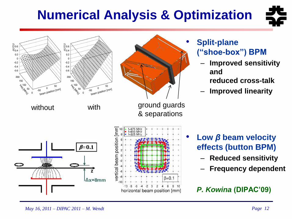
Numerical Analysis & Optimization
ground guards
& separations without with
• Split-plane
(“shoe-box”) BPM
– Improved sensitivity
and
reduced cross-talk
– Improved linearity
• Low β beam velocity
effects (button BPM)
– Reduced sensitivity
– Frequency dependent
P. Kowina (DIPAC‟09)

Page 13 May 16, 2011 – DIPAC 2011 – M. Wendt
Examples of Inductive BPMs
• Simple loop antenna (DESY)
– In-”air” (N2) application near the
beam dump
• Ferrite-loaded strip design (CERN)
– 100 nm resolution, BW: 0.1…30 MHz
• Deflection angle measurement idea (China)

Page 14 May 16, 2011 – DIPAC 2011 – M. Wendt
Resonant BPM Pickups
𝑓𝑚𝑛𝑝 =1
2𝜋 𝜇0휀0
𝑗𝑚𝑛𝑅
2
+𝑝𝜋
𝑙
2
𝐸𝑧 = 𝐶 𝐽1𝑗11𝑟
𝑅𝑒𝑖𝜔𝑡 cos𝜑
• “Pill-box” has eigenmodes
at:
• Beam couples to:
dipole (TM110) and
monopole (TM010)
& other modes
• Common mode (TM010)
frequency discrimination
• Mode polarization
– x-y cross-talk
• Normalization (intensity) &
phase reference

Page 15 May 16, 2011 – DIPAC 2011 – M. Wendt
Early Cavity BPMs (mid „90)
• Cold L-Band cavity BPM (DESY)
– Operates in TTF/FLASH
cryomodules
• High resolution C-Band cavity BPM
system (SLAC-FFTB)
– 3 cavity BPMs & reference cavity
– Correlated beam jitter subtracted:
-> 25 nm BPM resolution!

Page 16 May 16, 2011 – DIPAC 2011 – M. Wendt
Common-Mode Free Cavity BPM
• Add slot-coupled waveguide TE01-mode
high-pass filter
between cavity and coaxial output port.
– Finite Q of TM010 still leaks into TM110!
𝑓010 < 𝑓10 =1
2𝑎 휀𝜇 < 𝑓110
VLEPP 14 GHz
Cavity BPM
Setup of three VLEPP
cavity BPMs for ATF
(1997)
Page 17 May 16, 2011 – DIPAC 2011 – M. Wendt
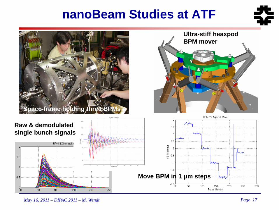
nanoBeam Studies at ATF
Ultra-stiff heaxpod
BPM mover
Space-frame holding three BPMs
Raw & demodulated
single bunch signals
Move BPM in 1 μm steps

Page 18 May 16, 2011 – DIPAC 2011 – M. Wendt
BPM Resolution Record!
• C-Band ILC IP-BPM (KEK)
– Narrow gap to be insensitive to the beam angle
– Small aperture (beam tube) for high sensitivity.
– x-y frequency separation (rectangular cavities).
– Double stage homodyne down-converter
8.7 nm position resolution!
port f (GHz) β Q0 Qext
X 5.712 1.4 5300 3901
Y 6.426 2 4900 2442

Page 19 May 16, 2011 – DIPAC 2011 – M. Wendt
LCLS Cavity BPM System
• 32 BPMs (ANL / SLAC)
– X-Band (11.4 GHz),
WG directly coupled to receiver (40 MHz).
• Typical resolution (median)
– σx ≈ 440 nm, a few BPMs >1 μm
– σy ≈ 230 nm, no BPM >1 μm
• Why the difference?!
– Offset? Jitter? Energy variation?

Page 20 May 16, 2011 – DIPAC 2011 – M. Wendt
ATF2 Cavity BPM System
• ATF2 cavity BPM system
– ~40 cavity BPMs
– 3 designs, C- & S-Band
– BPMs mounted on quads
• Signal processing
– Single-stage analog down-converter
– Digitalization and demodulation
• Objectives
– Resolution: <500 nm
– Precision: <1 %
– Stability: weeks
IP region
4 BPMs
S-Band BPMs
(movers) C-Band BPMs
(movers)
BPM test area
(low-Q, high-Q, tilt) strip-line / cavity BPMs
(rigid)
200
nm
40 nm
y x

Page 21 May 16, 2011 – DIPAC 2011 – M. Wendt

Page 22 May 16, 2011 – DIPAC 2011 – M. Wendt
Low-Q Cavity BPMs
• Compromise between
spatial and temporal resolution
– C-Band, Ql ≈ 50,
magnetic coupled coaxial port (SPring-8)
~200 nm resolution (test beam)
~30 psec TOF resolution (reference cavity)
– X-Band design study, Ql ≈ 250 (CLIC-CTF)
<50 nm resolution (anticipated)
<50 nsec integration time
8 mm beam pipe diameter!

Page 23 May 16, 2011 – DIPAC 2011 – M. Wendt
Strip-line / Coaxial Resonator BPMs
Cold re-entrant cavity BPM
(European-XFEL, Saclay)
Resonant strip-line BPM
(PSI-XFEL Injector)
Cold, WG-loaded, CM-free
L-Band re-entrant cavity BPM
(ILC, KEK)

Page 24 May 16, 2011 – DIPAC 2011 – M. Wendt
Read-out Electronics
ADC 900
CIC FIR
Σ
M
E
M
O
R
Y
NCO
I-Channel
Q-Channel same as I
NB
WB
raw
A B
C
D
BPF Att BPF LPF
Co
ord
inate
T
ransfo
rmatio
n
A-Electrode Analog Conditioning
B, C, D Analog same as A
Ctrl LO
CLK & Timing
A Data
• Typical BPM read-out scheme
– Separate analog signal
processing for the channels
– Analog down-converter if
undersampling is not applicable.

Page 25 May 16, 2011 – DIPAC 2011 – M. Wendt
Some Remarks
• Analog down-converter / signal conditioning
– Defines the TD waveform / frequency band to be digitized.
– May need to be located close to the BPM pickup
(e.g. pickup input frequencies in the microwave range)
– Analog down-conversion vs. undersampling!?
CLK jitter requirements
– Linearity / dynamic range extension (attenuator / gain switching)
– May need calibration & gain correction system
• Digital signal processing
– FPGA vs. CPU processing
– I-Q is only required if ADC CLK is not phase locked to fRF
– Down-conversion to base-band, low frequency but not DC
Crawling phase
– Coordinate transformation √I2+Q2 vs. rotation to I‟?!
• Key elements: Dynamic range (linearity) & statistics (sample-rate)!
tjitter
Aerror
signal

Page 26 May 16, 2011 – DIPAC 2011 – M. Wendt
Typical Performance
BSP-100 module
(APS ANL) Libera Brilliance
(@APS ANL)

Page 27 May 16, 2011 – DIPAC 2011 – M. Wendt
BPM Electronics Scheme (ATF DR)
A B
C D
up
down
out in
DCBA
CBDAH
)()(
DCBA
DCBAV
)()(
53 79.700.135.9][ mmPos
714 15.1
Down Mix A
714 15.1
Down Mix B
714 15.1
Down Mix C
714 15.1
Down Mix D
Digital signal
processing:
1D polynomial fit:
0.1 dB gain error ≡
27 µm offset error !
(we now use a 7th order 2D fit)

Page 28 May 16, 2011 – DIPAC 2011 – M. Wendt
Automatic Gain Correction (ATF DR BPMs)
• Use calibration tone(s)
– 714+ε MHz, 714-ε MHz
– Reflected and/or thru BPM
calibration signal
– Inside analog pass-band
– Separate DDC in NB mode
– Error & correction signals:
• Advice:
– Two calibration tones is not
a good idea!
(use “ping-pong” calibration
workaround)
𝑋Err =𝐴CAL + 𝐵CAL + 𝐶CAL + 𝐷CAL
4 𝑋CAL
𝑋Corr = 𝑋raw 𝑋Err 𝑋: 𝐴, 𝐵, 𝐶, 𝐷
MOPD11
(Nathan Eddy)

Page 29 May 16, 2011 – DIPAC 2011 – M. Wendt
Libera Crossbar Switch CAL Scheme
Schematics of crossbar switch based BPM electronics from Istrumentation Technologies. Pat. No.: US2004/0222778 A1

Page 30 May 16, 2011 – DIPAC 2011 – M. Wendt
Summary & Final Remarks
• A lot of BPM R&D activities worldwide, labs & industry
– Pickups & feedthroughs, electronics, etc.
• Trent towards high resolution resonant BPMs, e.g. cavity BPMs
– In favor of higher, microwave frequencies
– Demands in precision mechanics, tolerances, EM simulations
(also higher costs)
• Trent to digital signal processing, plus some analog electronics
with integrated calibration / drift correction scheme.
– Complex processing / math in the digital domain.
– Very flexible by FPGA re-programming, however labor intensive!
• Many open points and issues to be further discussed!
• This short overview could only give a glimpse
– Missing: Beam phase / TOF monitoring, BPM as beam intensity
monitor, tilt (angle), wake-potential, invasive (screens) & optical BPMs.
– Our large, world-wide distributed community needs events like this to
exchange information and experience!
Page 31 May 16, 2011 – DIPAC 2011 – M. Wendt
THANKS!