Overview of Chapter 3 °K-maps: an alternate approach to representing Boolean functions °K-map...
60
Overview of Chapter 3 ° K-maps: an alternate approach to representing Boolean functions ° K-map representation can be used to minimize Boolean functions ° Easy conversion from truth table to K-map to minimized SOP representation. ° Simple rules (steps) used to perform minimization ° Leads to minimized SOP representation. • Much faster and more more efficient than previous minimization techniques with Boolean algebra.
-
Upload
horace-bryan -
Category
Documents
-
view
218 -
download
0
Transcript of Overview of Chapter 3 °K-maps: an alternate approach to representing Boolean functions °K-map...
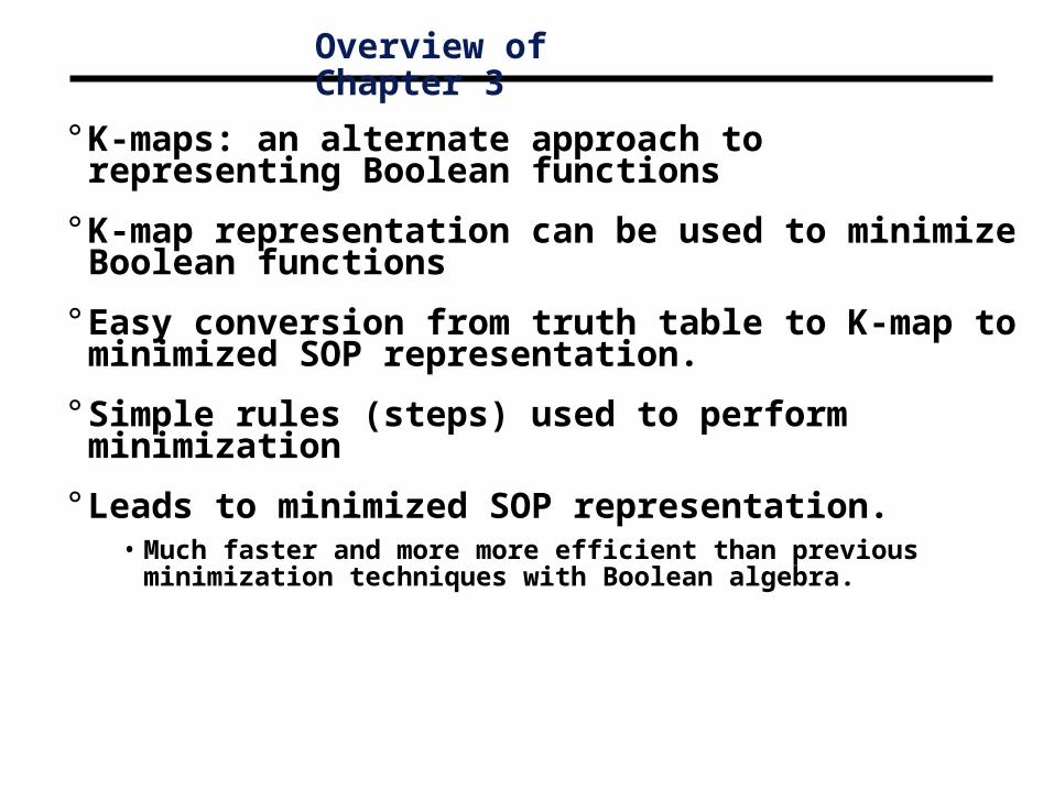
Overview of Chapter 3
° K-maps: an alternate approach to representing Boolean functions
° K-map representation can be used to minimize Boolean functions
° Easy conversion from truth table to K-map to minimized SOP representation.
° Simple rules (steps) used to perform minimization
° Leads to minimized SOP representation.• Much faster and more more efficient than previous minimization
techniques with Boolean algebra.
x y F
0 0 1
0 1 1
1 0 0
1 1 0
Karnaugh maps
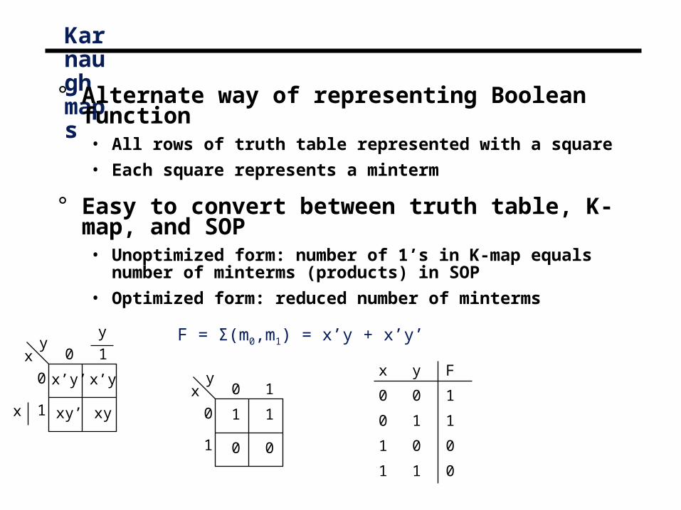
° Alternate way of representing Boolean function• All rows of truth table represented with a square
• Each square represents a minterm
° Easy to convert between truth table, K-map, and SOP• Unoptimized form: number of 1’s in K-map equals number of
minterms (products) in SOP
• Optimized form: reduced number of minterms
0 1y
x
0
1
1
0 0
1
0 1y
x
0
1
x’y’
xy’ xy
x’y
x
y F = Σ(m0,m1) = x’y + x’y’

Karnaugh Maps
° A Karnaugh map is a graphical tool for assisting in the general simplification procedure.
° Two variable maps.
0A
1 01
B 0 101
F=AB +A’B 0A
1 11
B 0 101
° Three variable maps.
0A
1 11
00 01
01
BC
01 1
111 10
F=AB’C’ +AB C +ABC +ABC + A’B’C + A’BC’
F=AB +AB +AB
A B C F0 0 0 00 0 1 10 1 0 10 1 1 01 0 0 11 0 1 11 1 0 11 1 1 1
+

Rules for K-Maps
We can reduce functions by circling 1’s in the K-map
Each circle represents minterm reduction
Following circling, we can deduce minimized and-or form.
Rules to consider
Every cell containing a 1 must be included at least once.
The largest possible “power of 2 rectangle” must be enclosed.
The 1’s must be enclosed in the smallest possible number of rectangles.
Example

Karnaugh Maps
° A Karnaugh map is a graphical tool for assisting in the general simplification procedure.
° Two variable maps.
0A
1 01
B 0 101
F=AB +A’B 0A
1 11
B 0 101 F=A+B
° Three variable maps.
F=A+B C +BC 0
A
1 11
00 01
01
BC
01 1
111 10
F=AB +AB +AB
F=AB’C’ +AB C +ABC +ABC + A’B’C + A’BC’

Karnaugh maps
° Numbering scheme based on Gray–code• e.g., 00, 01, 11, 10
• Only a single bit changes in code for adjacent map cells
• This is necessary to observe the variable transitions
00 01AB
C
0
1
11 10
C
B
A
F(A,B,C) = m(0,4,5,7)
G(A,B,C) = 0 0
0 0
1 1
1 1C
B
A
1 0
0 0
0 1
1 1C
B
A
A
= AC + B’C’

More Karnaugh Map Examples
° Examples
g = b'
0 101
ab
cab
00 01 11 1001
0 101
ab
cab
00 01 11 1001
0 10 1
f = a
0 0 1 00 1 1 1
cout = ab + bc + ac
1 10 0
0 0 1 10 0 1 1
f = a
1. Circle the largest groups possible.2. Group dimensions must be a power of 2. 3. Remember what circling means!

Application of Karnaugh Maps: The One-bit Adder
Adder
Cin
Cout
SB
A
A B Cin S Cout0 0 0 0 00 0 1 1 00 1 0 1 00 1 1 0 11 0 0 1 01 0 1 0 11 1 0 0 11 1 1 1 1
+
S = A’B’Cin + A’BCin’ + A’BCin + ABCin
Cout = A’BCin + A B’Cin + ABCin’ + ABCin
= A’BCin + ABCin + AB’Cin + ABCin + ABCin’ + ABCin
= BCin + ACin + AB
= (A’ + A)BCin + (B’ + B)ACin + (Cin’ + Cin)AB
= 1·BCin + 1· ACin + 1· AB
How to use a KarnaughMap instead of the
Algebraic simplification?

Application of Karnaugh Maps: The One-bit Adder
Adder
Cin
Cout
SB
A
A B Cin S Cout0 0 0 0 00 0 1 1 00 1 0 1 00 1 1 0 11 0 0 1 01 0 1 0 11 1 0 0 11 1 1 1 1
+
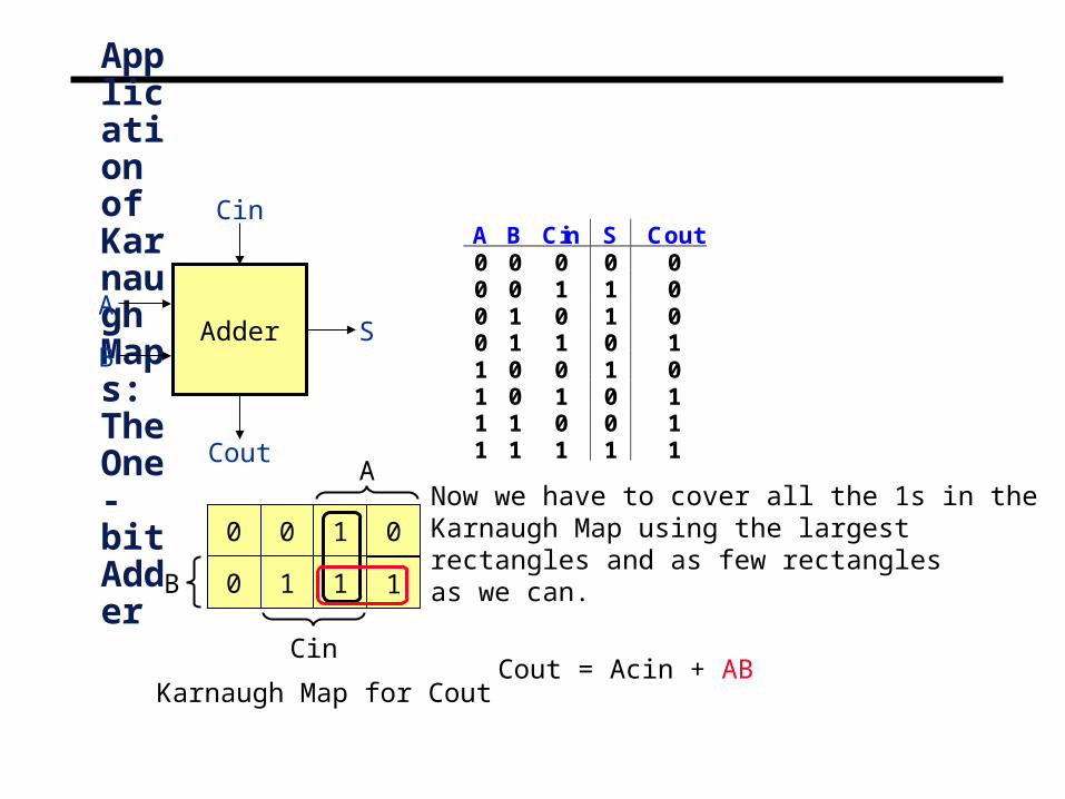
Karnaugh Map for Cout
Now we have to cover all the 1s in theKarnaugh Map using the largestrectangles and as few rectanglesas we can.
A
B
Cin
0
0
0
1 1 1
01

A
B
Cin
Application of Karnaugh Maps: The One-bit Adder
Adder
Cin
Cout
SB
A
A B Cin S Cout0 0 0 0 00 0 1 1 00 1 0 1 00 1 1 0 11 0 0 1 01 0 1 0 11 1 0 0 11 1 1 1 1
+
0
0
0 01
1 1 1
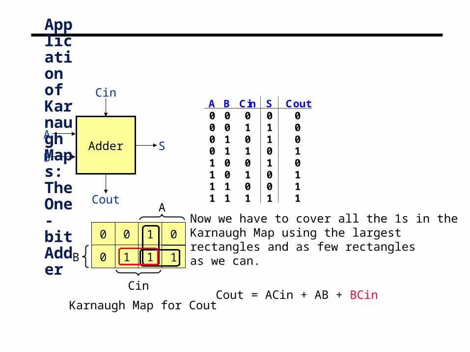
Karnaugh Map for Cout
Now we have to cover all the 1s in theKarnaugh Map using the largestrectangles and as few rectanglesas we can.
Cout = ACin
A
B
Cin
Application of Karnaugh Maps: The One-bit Adder
Adder
Cin
Cout
SB
A
A B Cin S Cout0 0 0 0 00 0 1 1 00 1 0 1 00 1 1 0 11 0 0 1 01 0 1 0 11 1 0 0 11 1 1 1 1
+
0
0
0 01
1 1 1
Karnaugh Map for Cout
Now we have to cover all the 1s in theKarnaugh Map using the largestrectangles and as few rectanglesas we can.
Cout = Acin + AB
A
B
Cin
Application of Karnaugh Maps: The One-bit Adder
Adder
Cin
Cout
SB
A
A B Cin S Cout0 0 0 0 00 0 1 1 00 1 0 1 00 1 1 0 11 0 0 1 01 0 1 0 11 1 0 0 11 1 1 1 1
+
0
0
0 01
1 1 1
Karnaugh Map for Cout
Now we have to cover all the 1s in theKarnaugh Map using the largestrectangles and as few rectanglesas we can.
Cout = ACin + AB + BCin

A
B
Cin
Application of Karnaugh Maps: The One-bit Adder
Adder
Cin
Cout
SB
A
A B Cin S Cout0 0 0 0 00 0 1 1 00 1 0 1 00 1 1 0 11 0 0 1 01 0 1 0 11 1 0 0 11 1 1 1 1
+
0
1
1 10
0 1 0
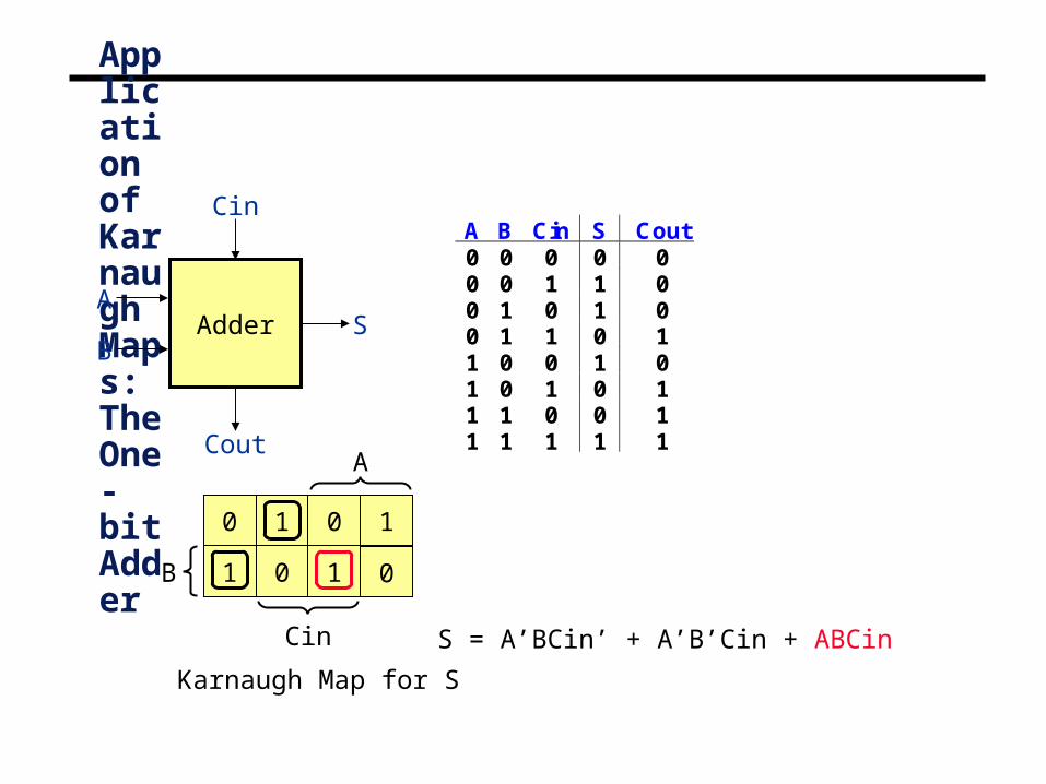
Karnaugh Map for S
S = A’BCin’

A
B
Cin
Application of Karnaugh Maps: The One-bit Adder
Adder
Cin
Cout
SB
A
A B Cin S Cout0 0 0 0 00 0 1 1 00 1 0 1 00 1 1 0 11 0 0 1 01 0 1 0 11 1 0 0 11 1 1 1 1
+
0
1
1 10
0 1 0
Karnaugh Map for S
S = A’BCin’ + A’B’Cin
A
B
Cin
Application of Karnaugh Maps: The One-bit Adder
Adder
Cin
Cout
SB
A
A B Cin S Cout0 0 0 0 00 0 1 1 00 1 0 1 00 1 1 0 11 0 0 1 01 0 1 0 11 1 0 0 11 1 1 1 1
+
0
1
1 10
0 1 0
Karnaugh Map for S
S = A’BCin’ + A’B’Cin + ABCin

A
B
Cin
Application of Karnaugh Maps: The One-bit Adder
Adder
Cin
Cout
SB
A
A B Cin S Cout0 0 0 0 00 0 1 1 00 1 0 1 00 1 1 0 11 0 0 1 01 0 1 0 11 1 0 0 11 1 1 1 1
+
0
1
1 10
0 1 0
Karnaugh Map for S
S = A’BCin’ + A’B’Cin + ABCin + AB’Cin’
No Possible Reduction!
Can you draw the circuit diagrams?

Karnaugh Maps for Four Input Functions
° Represent functions of 4 inputs with 16 minterms
° Use same rules developed for 3-input functions
° Note bracketed sections shown in example.
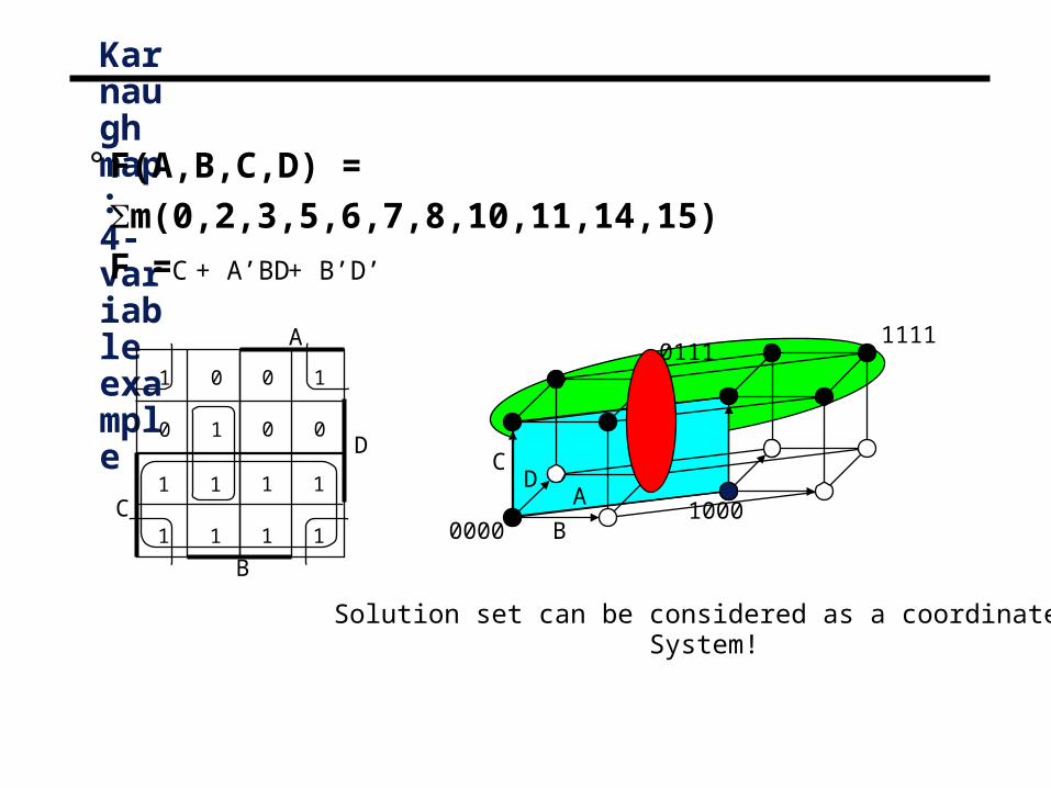
C + B’D’
Solution set can be considered as a coordinate System!
Karnaugh map: 4-variable example
° F(A,B,C,D) = m(0,2,3,5,6,7,8,10,11,14,15)
F =
D
A
B
A
B
CD
0000
1111
1000
01111 0
0 1
0 1
0 0
1 1
1 1
1 1
1 1C
+ A’BD

A' B' D + A' C + B' C D
B C' D' + A C' + A B D'
LT =
EQ =
GT =
K-map for LT K-map for GT
Design examples
0 0
1 0
0 0
0 0D
A
1 1
1 1
0 1
0 0
B
C
K-map for EQ
1 0
0 1
0 0
0 0D
A
0 0
0 0
1 0
0 1
B
C
0 1
0 0
1 1
1 1D
A
0 0
0 0
0 0
1 0
B
C
Can you draw the truth table for these examples?
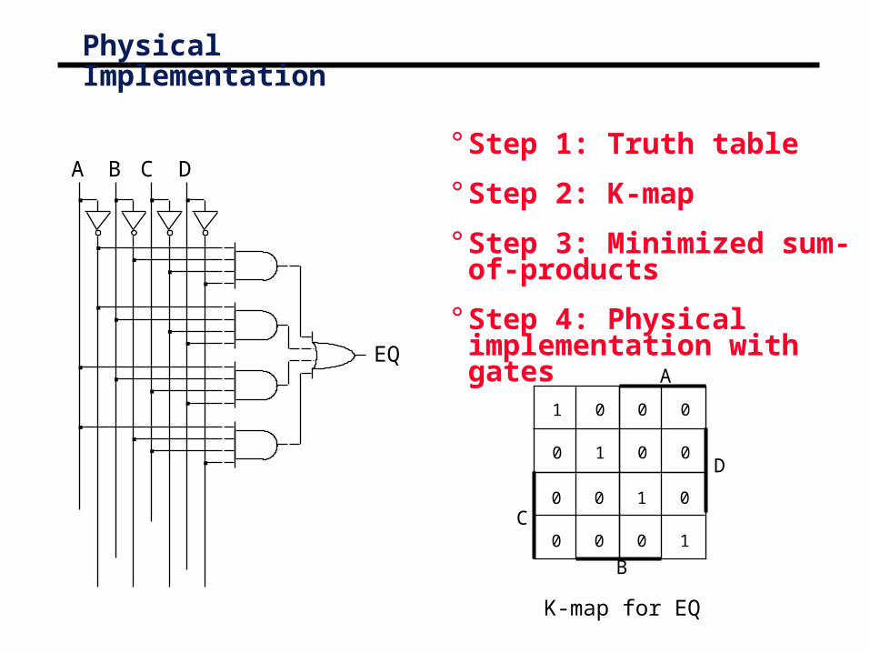
A'B'C'D' + A'BC'D + ABCD + AB'CD’
A B C D
EQ
Physical Implementation
° Step 1: Truth table
° Step 2: K-map
° Step 3: Minimized sum-of-products
° Step 4: Physical implementation with gates
K-map for EQ
1 0
0 1
0 0
0 0D
A
0 0
0 0
1 0
0 1
B
C

Karnaugh Maps
° Four variable maps.
F=BC +CD + AC+ AD
0AB
1 10
00 01
00
01
CD
00 1
111 10
F=ABC +ACD +ABC +AB CD +ABC +AB C
11 0
111
1011 1
1
° Need to make sure all 1’s are covered
° Try to minimize total product terms.
° Design could be implemented using NANDs and NORs

5-Variable K-Map
101198
13 141512
5 674
1 230
BC
DE
26 27 25 24
30 31 29 28
22 23 21 20
18 19 17 16
BC
DE
A=0
A=1
A’BCDE’
ABCDE’

Karnaugh maps: Don’t cares
° In some cases, outputs are undefined
° We “don’t care” if the logic produces a 0 or a 1
° This knowledge can be used to simplify functions.
0 0
1 1
X 0
X 1D
A
1 1
0 X
0 0
0 0
B
C
CDAB
00
01
11
10
00 01 11 10
- Treat X’s like either 1’s or 0’s- Very useful- OK to leave some X’s uncovered

+ C’D
Karnaugh maps: Don’t cares
° f(A,B,C,D) = m(1,3,5,7,9) + d(6,12,13)• without don't cares
- f =
0 0
1 1
X 0
X 1D
A
1 1
0 X
0 0
0 0
B
C
A’D
CDAB
00
01
11
10
00 01 11 10
C f0 00 11 01 10 00 11 X100110011
D0101010101010101
10100XX00
A0000000011111111
+
B0000111100001111
+
Don’t Care Conditions
° In some situations, we don’t care about the value of a function for certain combinations of the variables.• these combinations may be impossible in certain contexts
• or the value of the function may not matter in when the combinations occur
° In such situations we say the function is incompletely specified and there are multiple (completely specified) logic functions that can be used in the design.• so we can select a function that gives the simplest circuit
° When constructing the terms in the simplification procedure, we can choose to either cover or not cover the don’t care conditions.

Map Simplification with Don’t Cares
F=ACD+B+AC0
AB
x x1
00 01
00
01
CD
0x 1
011 10
1x 0
111
1011 1
x
0AB
x x1
00 01
00
01
CD
0x 1
011 10
1x 0
111
1011 1
xF=ABCD+ABC+BC+AC
° Alternative covering.

Karnaugh maps: don’t cares (cont’d)
° f(A,B,C,D) = m(1,3,5,7,9) + d(6,12,13)• f = A'D + B'C'D without don't cares
• f = with don't cares
don't cares can be treated as1s or 0s
depending on which is more advantageous
0 0
1 1
X 0
X 1D
A
1 1
0 X
0 0
0 0
B
C
A'D
by using don't care as a "1"a 2-cube can be formed rather than a 1-cube to coverthis node
+ C'D
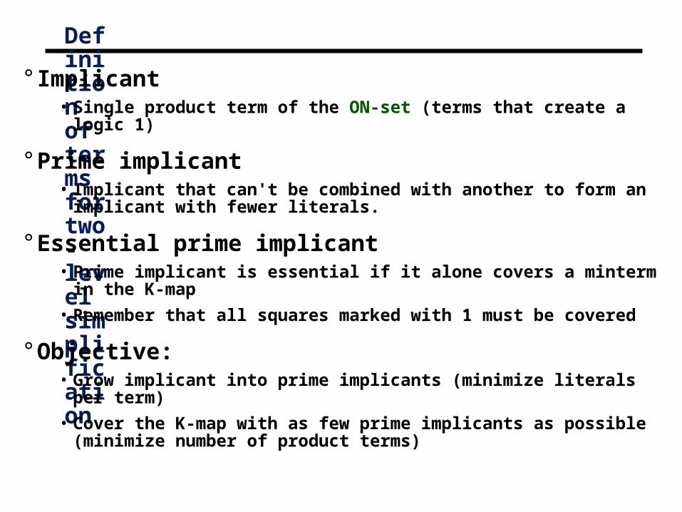
Definition of terms for two-level simplification
° Implicant• Single product term of the ON-set (terms that create a logic 1)
° Prime implicant• Implicant that can't be combined with another to form an implicant with
fewer literals.
° Essential prime implicant• Prime implicant is essential if it alone covers a minterm in the K-map
• Remember that all squares marked with 1 must be covered
° Objective:• Grow implicant into prime implicants (minimize literals per term)
• Cover the K-map with as few prime implicants as possible(minimize number of product terms)

0 X
1 1
1 0
1 0D
A
1 0
0 0
1 1
1 1
B
C
5 prime implicants:BD, ABC', ACD, A'BC, A'C'D
Examples to illustrate terms
0 0
1 1
1 0
1 0D
A
0 1
0 1
1 1
0 0
B
C
6 prime implicants:A'B'D, BC', AC, A'C'D, AB, B'CD
minimum cover: AC + BC' + A'B'D
essential
minimum cover: 4 essential implicants
essential

Prime Implicants
Any single 1 or group of 1s in the Karnaugh map of afunction F is an implicant of F.A product term is called a prime implicant of F if itcannot be combined with another term to eliminate avariable.
B
C
A
1
1
1
1 1
1 1
1
D
Example:
If a function F is represented bythis Karnaugh Map. Which of thefollowing terms are implicants ofF, and which ones are primeimplicants of F?
(a) AC’D’(b) BD(c) A’B’C’D’(d) AC’(e) B’C’D’
Implicants:(a),(c),(d),(e)
Prime Implicants:(d),(e)

Essential Prime Implicants
A product term is an essential prime implicant if there is a minterm that is only covered by that prime implicant.
- The minimal sum-of-products form of F must includeall the essential prime implicants of F.

NAND-NAND & NOR-NOR Networks
DeMorgan’s Law:
(a + b)’ = a’ b’ (a b)’ = a’ + b’
a + b = (a’ b’)’ (a b) = (a’ + b’)’
push bubbles or introduce in pairs or remove pairs.
= =
==

NAND-NAND Networks
° Mapping from AND/OR to NAND/NAND
ab
cd
a) b)
c) d)

Implementations of Two-level Logic
° Sum-of-products• AND gates to form product terms
(minterms)
• OR gate to form sum
° Product-of-sums• OR gates to form sum terms
(maxterms)
• AND gates to form product

Two-level Logic using NAND Gates
° Replace minterm AND gates with NAND gates
° Place compensating inversion at inputs of OR gate
Two-level Logic using NAND Gates (cont’d)
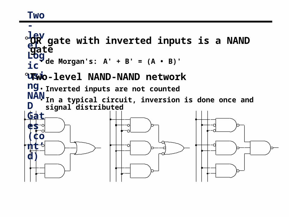
° OR gate with inverted inputs is a NAND gate• de Morgan's: A' + B' = (A • B)'
° Two-level NAND-NAND network• Inverted inputs are not counted
• In a typical circuit, inversion is done once and signal distributed

Conversion Between Forms
° Convert from networks of ANDs and ORs to networks of NANDs and NORs
• Introduce appropriate inversions ("bubbles")
° Each introduced "bubble" must be matched by a corresponding "bubble"
• Conservation of inversions
• Do not alter logic function
° Example: AND/OR to NAND/NAND
A
B
C
D
Z
A
B
C
D
Z
NAND
NAND
NAND
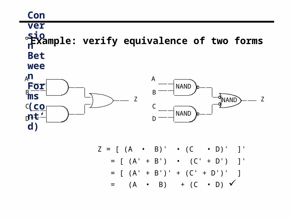
Z = [ (A • B)' • (C • D)' ]'
= [ (A' + B') • (C' + D') ]'
= [ (A' + B')' + (C' + D')' ]
= (A • B) + (C • D)
Conversion Between Forms (cont’d)
° Example: verify equivalence of two forms
A
B
C
D
Z
A
B
C
D
Z
NAND
NAND
NAND
Conversion to NAND Gates
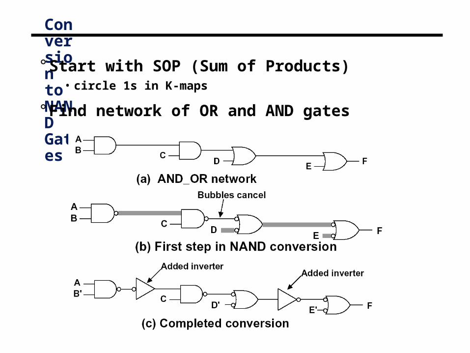
° Start with SOP (Sum of Products)• circle 1s in K-maps
° Find network of OR and AND gates

ABC
DE
FG
X
Multi-level Logic
° x = A D F + A E F + B D F + B E F + C D F + C E F + G• Reduced sum-of-products form – already simplified
• 6 x 3-input AND gates + 1 x 7-input OR gate (may not exist!)
• 25 wires (19 literals plus 6 internal wires)
° x = (A + B + C) (D + E) F + G• Factored form – not written as two-level S-o-P
• 1 x 3-input OR gate, 2 x 2-input OR gates, 1 x 3-input AND gate
• 10 wires (7 literals plus 3 internal wires)

Level 1 Level 2 Level 3 Level 4
originalAND-OR network
A
CD
B
BC’
F
introduction andconservation of
bubblesA
CD
B
BC’
F
redrawn in termsof conventional
NAND gates A
CD
B’
BC’
F
Conversion of Multi-level Logic to NAND Gates° F = A (B + C D) + B C'

A
XBC
D
F(a)
Original circuit
A
XBC
D
F(b)
Add double bubbles at inputs
D’
A
X’
BC
F(c)
Distribute bubblessome mismatches
D’
AX
BC
FX’
(d)
Insert inverters to fix mismatches
Conversion Between Forms
° Example

Exclusive-OR and Exclusive-NOR Circuits
Exclusive-OR (XOR) produces a HIGH output whenever the two inputs are at opposite levels.

Exclusive-NOR (XNOR) :
Exclusive-NOR (XNOR) produces a HIGH output whenever the two inputs are at the same level.
Exclusive-NOR Circuits

XNOR gate may be used to simplify circuit implementation.
Exclusive-NOR Circuits

XOR Function° XOR function can also be implemented with AND/OR gates (also NANDs).

XOR Function
° Even function – even number of inputs are 1.
° Odd function – odd number of inputs are 1.
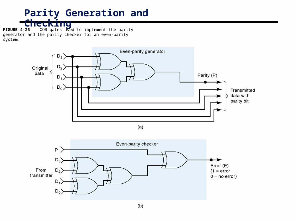
FIGURE 4-25 XOR gates used to implement the parity generator and the parity checker for an even-parity system.
Parity Generation and Checking

° Important concept – analyze digital circuits• Given a circuit
- Create a truth table
- Create a minimized circuit
° Approaches• Boolean expression approach
• Truth table approach
° Leads to minimized hardware
° Provides insights on how to design hardware• Tie in with K-maps (next time)
Digital Circuit Analysis

The Problem
° How can we convert from a circuit drawing to an equation or truth table?
° Two approaches
° Create intermediate equations
° Create intermediate truth tables
ABC
A
B
C’
Out

Label Gate Outputs
1. Label all gate outputs that are a function of input variables.
2. Label gates that are a function of input variables and previously labeled gates.
3. Repeat process until all outputs are labelled.
ABC
A
B
C’
Out
R
S T

Approach 1: Create Intermediate Equations
Step 1: Create an equation for each gate output based on its input.
• R = ABC
• S = A + B
• T = C’S
• Out = R + T
ABC
A
B
C’
Out
R
S T

Approach 1: Substitute in subexpressions
Step 2: Form a relationship based on input variables (A, B, C)
• R = ABC
• S = A + B
• T = C’S = C’(A + B)
• Out = R+T = ABC + C’(A+B)
ABC
A
B
C’
Out
R
S T

Approach 1: Substitute in subexpressions
Step 3: Expand equation to SOP final result
• Out = ABC + C’(A+B) = ABC + AC’ + BC’
A
C’
Out
B
C’
ABC
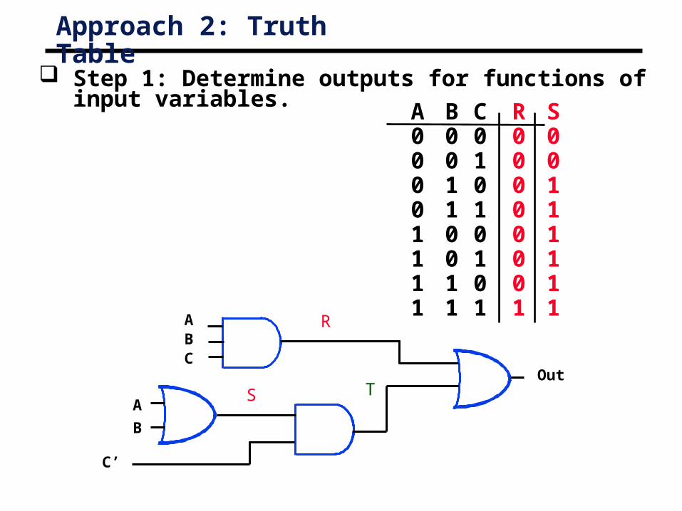
Approach 2: Truth Table
Step 1: Determine outputs for functions of input variables.
A00001111
B00110011
C01010101
R00000001
S00111111
ABC
A
B
C’
Out
R
S T

Approach 2: Truth Table
Step 2: Determine outputs for functions of intermediate variables.
A00001111
B00110011
C01010101
T = S * C’
R00000001
S00111111
T00101010
C’10101010A
BC
A
B
C’
Out
R
S T

Approach 2: Truth Table
Step 3: Determine outputs for function.
A00001111
B00110011
C01010101
R00000001
S00111111
T00101010
Out 0 0 1 0 1 0 1 1
R + T = Out
ABC
A
B
C’
Out
R
S T
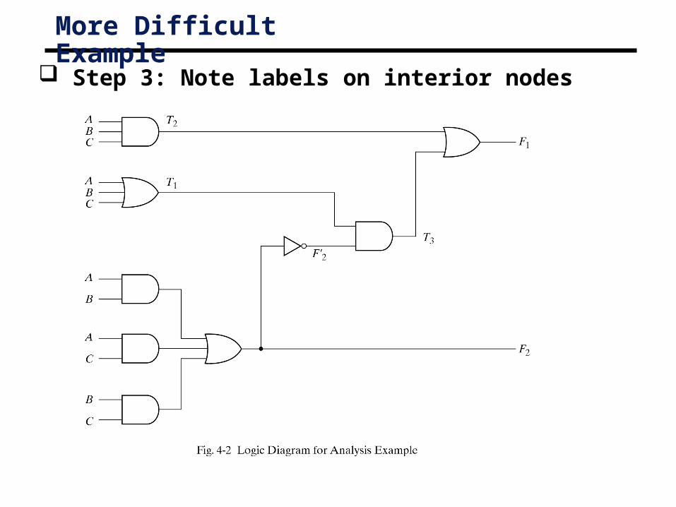
More Difficult Example
Step 3: Note labels on interior nodes

More Difficult Example: Truth Table
Remember to determine intermediate variables starting from the inputs.
When all inputs determined for a gate, determine output.
The truth table can be reduced using K-maps.
A00001111
B00110011
C01010101
F2
00010111
F’2
11101000
T1
01111111
T2
00000001
T3
01101000
F1
01101001

Summary
° Important to be able to convert circuits into truth table and equation form
• WHY? ---- leads to minimized sum of product representation
° Two approaches illustrated• Approach 1: Create an equation with circuit output dependent on
circuit inputs
• Approach 2: Create a truth table which shows relationship between circuit inputs and circuit outputs
° Both results can then be minimized using K-maps.
° Next time: develop a minimized SOP representation from a high level description