
Oversized Cargo M-Series Truck Vehicle Management Codes ...
108
DEPARTMENT OF THE AIR FORCE Headquarters US Air Force QTP24-3-K212 14 January 2019 Washington, D.C. 20330-1030 Oversized Cargo M-Series Truck Vehicle Management Codes: K212, K237, K248, K251, K460 – K471 QUALIFICATION TRAINING PACKAGE
Transcript of Oversized Cargo M-Series Truck Vehicle Management Codes ...

DEPARTMENT OF THE AIR FORCE Headquarters US Air Force
QTP24-3-K212 14 January 2019
Washington, D.C. 20330-1030
Oversized Cargo M-Series Truck Vehicle Management Codes: K212, K237, K248, K251, K460 – K471
QUALIFICATION TRAINING PACKAGE

CONTENTS
SECTION 1—OVERVIEW ......................................................................................................... 3 1.1. Overview.......................................................................................................................................................... 3
SECTION 2—RESPONSIBILITIES .......................................................................................... 3 2.1. Responsibilities. .............................................................................................................................................. 3
SECTION 3—INTRODUCTION................................................................................................ 4 3.1. Objectives. ....................................................................................................................................................... 4
3.2. Desired Learning Outcomes. ......................................................................................................................... 4
3.3. Lesson Duration. ............................................................................................................................................. 5
3.4. Instructional References. ............................................................................................................................... 5
3.5. Instructional Training Aids and Equipment. ............................................................................................... 5
SECTION 4—TRAINEE PREPARATION ............................................................................... 6 4.1. Licensing Requirements. ................................................................................................................................ 6
4.2. Required Reading. .......................................................................................................................................... 6
SECTION 5—KNOWLEDGE LECTURE AND EVALUATION .......................................... 6 5.1. Knowledge Overview. ..................................................................................................................................... 6
5.2. Overview of Training and Requirements. .................................................................................................... 7
5.3. Vehicle Inspection. .......................................................................................................................................... 9 5.4. Vehicle Safety and Equipment. ................................................................................................................... 13
5.5. Driving Safety and Precautions. .................................................................................................................. 14
5.6. Vehicle Operation. ........................................................................................................................................ 17
5.7. Maintenance Procedures. ............................................................................................................................. 35
SECTION 6—EXPLANATION AND DEMONSTRATION. ................................................ 79 6.1. Instructor’s Preparation. ............................................................................................................................. 79
6.2. Safety Procedures and Equipment. ............................................................................................................. 79 6.3. Operator Maintenance Demonstration. ...................................................................................................... 80
6.4. Operation Demonstration. ........................................................................................................................... 80
SECTION 7—TRAINEE PERFORMANCE AND EVALUATION ..................................... 82 7.1. Trainee Performance. ................................................................................................................................... 82
7.2. Performance Evaluation. ............................................................................................................................. 85
Attachment 1—GLOSSARY OF REFERENCES AND SUPPORTING INFORMATION 90
Attachment 2—VEHICLE INSPECTION GUIDE 91
Attachment 3—PERFORMANCE TEST 95
Attachment 4—SEVEN-STEP INSPECTION PROCESS 100

Section 1—OVERVIEW 1.1. Overview.
1.1.1. Send comments and suggested improvements on Air Force (AF) Form 847, Recommendation for Change of Publication, through Air Force Installation and Mission Support Center (AFIMSC) functional managers via e-mail at [email protected]. 1.1.2. How to use this plan:
1.1.2.1. Instructor:
1.1.2.1.1. Provide overview of training, Section 2 and Section 3. 1.1.2.1.2. Instructor’s lesson plan for trainee preparation, give classroom lecture, Section 4. 1.1.2.1.3. Instructor’s lesson plan for knowledge training, Section 5. 1.1.2.1.4. Instructor’s lesson plan for demonstration, Section 6. 1.1.2.1.5. Instructor’s lesson plan for performance and evaluation, Section 7.
1.1.2.2. Trainee:
1.1.2.2.1. Reads this entire lesson plan prior to starting lecture. 1.1.2.2.2. Follows along with lecture using this lesson plan and its attachments. 1.1.2.2.3. Uses Attachment 2 and Attachment 4 as guides for vehicle inspection. 1.1.2.2.4. Takes performance test.
Section 2—RESPONSIBILITIES 2.1. Responsibilities.
2.1.1. The trainee shall:
2.1.1.1. Ensure the trainer explains the Air Force Qualification Training Plan (AFQTP) process and the responsibilities. 2.1.1.2. Review the AFQTP/Module/Unit with the trainer.

2.1.1.3. The trainee should ask questions if he/she does not understand the objectives for each unit. 2.1.1.4. Review missed questions with the trainer.
2.1.2. Instructor shall:
2.1.2.1. Review the AFQTP with the trainee. 2.1.2.2. Conduct knowledge training with the trainee using the AFQTP. 2.1.2.3. Grade the review questions using the answer key. 2.1.2.4. Review missed questions with the trainee to ensure the required task knowledge has been gained to complete the task. 2.1.2.5. Sign-off the task(s).
2.1.3. The Certifier shall:
2.1.3.1. Evaluate the Airman’s task performance without assistance. 2.1.3.2. Sign-off the task(s).
Section 3—INTRODUCTION 3.1. Objectives.
3.1.1. Given lectures, demonstrations, hands-on driving session and a performance test, trainees will be able to perform operator’s inspection and complete the performance test with zero instructor assists.
3.1.1.1. Train and qualify each trainee in safe operation and preventive maintenance of the various oversized cargo M-series trucks. 3.1.1.2. This training will ensure the trainee becomes a qualified oversized cargo M-series truck operator; an operator who has the knowledge and skills to operate an oversized cargo M-series truck in a safe and professional manner.
3.2. Desired Learning Outcomes.
3.2.1. Understand the safety precautions to be followed pre-, during-, and ost- operation of the oversized cargo M-series truck. 3.2.2. Understand the purpose of the oversized cargo M-series truck and its role in the mission.

3.2.3. Know the proper operator maintenance procedures of the oversized cargo M-series truck, in accordance with (IAW) applicable technical orders (TOs) and use of AF Form 1800, Operator’s Inspection Guide and Trouble Report. 3.2.4. Safely and proficiently operate the oversized cargo M-series truck.
3.3. Lesson Duration.
3.3.1. Recommended instructional and hands on training time is 25 hours:
Figure 3.1. Recommended Training Time for Training Activities.
Training Activity Training Time Trainee’s Preparation 2 Hours Instructor’s Lecture and Demonstration 5 Hours Trainee’s Written Evaluation 1 Hour Trainee’s Personal Experience (to build confidence and proficiency) Perform Operator Maintenance Operate the Vehicle
15 Hours
Trainee’s Performance Evaluation 2 Hours Note: This is a recommended time; training time may be more or less depending how quickly a trainee learns new tasks.
3.4. Instructional References.
3.4.1. Risk Management (RM) and Safety Principles IAW AFPAM 90-803, Risk Management (RM) Guidelines and Tools. 3.4.2. Applicable TOs or Manufacturer’s Operator’s Manual.
3.4.2.1. T.O. 36A12 series
3.4.3. Air Force Manual (AFMAN) 24-306, Operation of Air Force Government Motor Vehicles. 3.4.4. AFI 91-203, Air Force Consolidated Occupational Safety Instruction. 3.4.5. AF Form 1800. 3.4.6. Special references based-off type of vehicle.
3.5. Instructional Training Aids and Equipment.
3.5.1. Oversized Cargo M-Series Truck Lesson Plan.
3.5.2. Oversized cargo M-series truck. 3.5.3. Applicable TO or manufacturer’s operator’s manual. 3.5.4. AF Form 1800. 3.5.5. Videos (if locally produced). 3.5.6. Suitable training area. 3.5.7. Traffic cones.
Section 4—TRAINEE PREPARATION 4.1. Licensing Requirements.
4.1.1. Trainee must have in his/her possession a valid state driver’s license. 4.1.2. AF Form 171, Request for Driver’s Training and Addition to U.S. Government Driver’s License IAW Air Force Instruction (AFI) 24-301, Ground Transportation. 4.1.3. Applicable local licensing jurisdiction requirements.
4.2. Required Reading.
4.2.1. Read this entire lesson plan. 4.2.2. Read AFMAN 24-306. 4.2.3. Read manufacturer’s operator’s manual for the vehicle being trained on.
4.2.4. Read recommended references:
4.2.4.1. T.O. 36A12 series
Section 5—KNOWLEDGE LECTURE AND EVALUATION 5.1. Knowledge Overview.
5.1.1. The AF uses a variety of oversized cargo M-series trucks. The primary purpose varies by vehicle type.

5.1.1.1. The primary purpose of the 2-1/2 ton 6 x 6 oversized cargo M-series truck is primarily airdrop recovery procedures that require the use of vehicles built for adverse terrain. Other oversized cargo M-series truck serve a variety of purposes (passenger movement, cargo movement, emergency services support, etc.)
5.2. Overview of Training and Requirements.
5.2.1. Training objectives:
5.2.1.1. Given lectures, demonstrations, hands-on driving session and a performance test, trainees will be able to perform operator’s inspection and complete the performance test with zero instructor assists. 5.2.1.2. Train and qualify each trainee in safe operation and preventive maintenance of the various oversized cargo M-series trucks. 5.2.1.3. This training will ensure the trainee becomes a qualified oversized cargo M-series operator—an operator who has the knowledge and skills to operate an oversized cargo m-series truck in a safe and professional manner.
5.2.2. Desired learning outcomes:
5.2.2.1. Understand the safety precautions to be followed pre-, during-, and post- operation of the oversized cargo M-series trucks. 5.2.2.2. Understand the purpose of the oversized cargo M-series truck and its role in the mission.
5.2.2.2.1. Purpose various based on vehicle type (cargo movement, passenger movement, emergency services support, etc.). 5.2.2.2.2. Role in the mission (Unit/Base/Community (during natural disasters)/Air Force).
5.2.3. Oversized Cargo M-Series Truck Design. The design of an oversized cargo M-series truck varies depending on the vehicle type. Refer to the manufacturer’s operator’s manual for additional information on the specific oversized cargo M-series truck being operated, and to the data plate for safe load capacity guidance. The oversized cargo M-series truck normally can be identified by the following characteristics:
5.2.3.1. 2-1/2 and 5 Ton Trucks:
5.2.3.1.1. 2.5 ton or 5 ton refers to the maximum payload the vehicle can carry under the worst cross-country conditions. Under ideal highway conditions, it can carry twice as much.
5.2.3.1.2. The 6X6 designation means the vehicle has six wheel ends and all six are capable of driving.
5.2.3.1.3. The truck body provides 270 cubic feet of cargo space. The side racks have built-in troop’s seats for troop transport.
5.2.3.1.4. Use either diesel or JP-8 for fuel. JP-8 should only be used in an emergency and should be mixed with diesel as soon as possible.
5.2.3.1.5. Tire pressure is checked and adjusted automatically by the CTIS (Central Tire Inflation System).
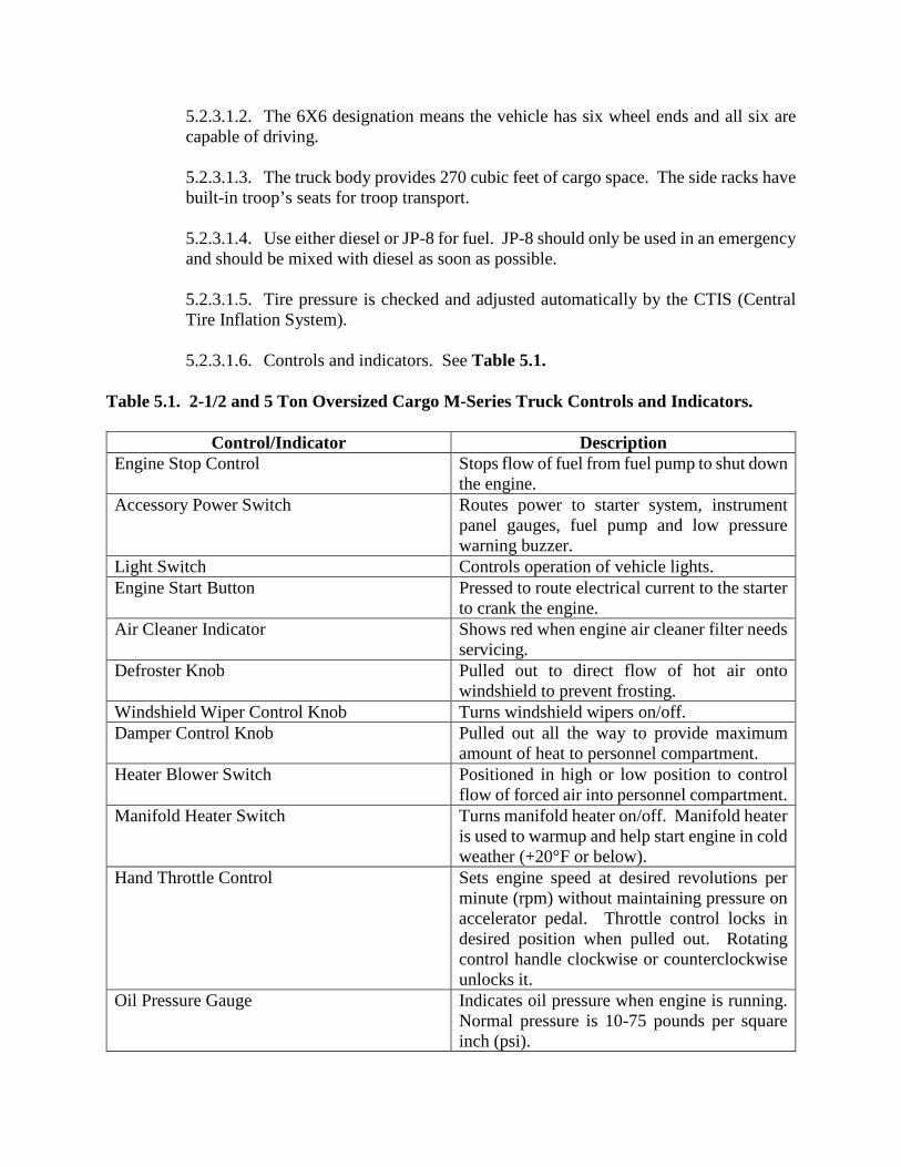
5.2.3.1.6. Controls and indicators. See Table 5.1.
Table 5.1. 2-1/2 and 5 Ton Oversized Cargo M-Series Truck Controls and Indicators.
Control/Indicator Description Engine Stop Control Stops flow of fuel from fuel pump to shut down
the engine. Accessory Power Switch Routes power to starter system, instrument
panel gauges, fuel pump and low pressure warning buzzer.
Light Switch Controls operation of vehicle lights. Engine Start Button Pressed to route electrical current to the starter
to crank the engine. Air Cleaner Indicator Shows red when engine air cleaner filter needs
servicing. Defroster Knob Pulled out to direct flow of hot air onto
windshield to prevent frosting. Windshield Wiper Control Knob Turns windshield wipers on/off. Damper Control Knob Pulled out all the way to provide maximum
amount of heat to personnel compartment. Heater Blower Switch Positioned in high or low position to control
flow of forced air into personnel compartment. Manifold Heater Switch Turns manifold heater on/off. Manifold heater
is used to warmup and help start engine in cold weather (+20°F or below).
Hand Throttle Control Sets engine speed at desired revolutions per minute (rpm) without maintaining pressure on accelerator pedal. Throttle control locks in desired position when pulled out. Rotating control handle clockwise or counterclockwise unlocks it.
Oil Pressure Gauge Indicates oil pressure when engine is running. Normal pressure is 10-75 pounds per square inch (psi).

Speedometer/Odometer Indicates vehicle speed and total mileage. Tachometer Indicates engine speed in revolutions per
minute (rpm) and operation time in hours and tenths of hours.
Engine Coolant Temperature Gauge Indicates temperature of engine coolant. Normal operating temperature is 180° to 200°F.
Map Compartment Provides storage for manuals, forms and maps. Air Pressure Gauge Indicates pressure in air reservoir tanks.
Normal pressure is 85 to 120 psi. Battery/Generator Gauge Indicates when the battery is charging or
discharging. Front Wheel Drive Lever Engages/disengages front wheel drive power. Front Wheel Drive Indicator Light Shows when front wheel drive is operating. Fuel Lever Gauge Indicates fuel level in fuel tank. High Beam Indicator Shows when headlights are on high beam. Transfer Case Shift Lever Pushed down to “Low” range for heavy load
operations, and pulled up to “High” range for light load operations.
Slave Receptacle Located on the right rear side of the cab, it is the plug-in point for an external power service required to slave start vehicle when batteries have become discharged.
5.2.3.2. The 6x6 System (if applicable). A vehicle equipped with six wheel drive (6x6) has the ability to use all six wheels to power itself. This increases traction which may enable the operator to safely drive over terrain and road conditions that a conventional two wheel drive (2x2) or four wheel drive (4x4) drive vehicle cannot.
5.2.3.2.1. Power is supplied to all six wheels through a transfer case or power transfer unit. 6x6 vehicles allow the operator to select different drive modes as necessary.
5.2.3.2.2. Refer to the manufacturer’s operator’s manual for information on shifting procedures and maintenance. 5.2.3.2.3. On some 6x6 models, the initial shift from 2x2/4x4 to 6x6 while the vehicle is moving can cause a momentary clunk and ratcheting sound. These sounds are normal as the front drivetrain comes up to speed and is not cause for concern.
5.3. Vehicle Inspection.
5.3.1. Pre-trip vehicle inspection test. Use Attachment 2 as a walk around guide along with AF Form 1800.
5.3.1.1. The following items must be checked when the vehicle is picked up:

5.3.1.1.1. Ensure all correct documentation is in the package when the vehicle is picked up.
5.3.1.1.1.1. AF Form 1800 Form. Ensure the following are annotated on it:
5.3.1.1.1.1.1. Reg. Number of vehicle matches what is on the AFTO Form. 5.3.1.1.1.1.2. Signatures for Tire Pressure Check/Stencil verification.
5.3.1.1.1.1.3. Miles/Hours of Vehicle/Date. Record off-base mileage slip (Write down mileage when leaving/returning from base). Off base fuel is taxed).
5.3.1.1.1.1.4. No open write-ups.
5.3.1.1.1.1.5. Note any discrepancies found on the space provided inside Form 1800 and notify Vehicle Maintenance personnel. 5.3.1.1.1.1.6. Ensure that the fire extinguishers have been signed off for the month.
5.3.1.1.1.2. Waiver Card. 5.3.1.1.1.3. Vehicle Accident Report.
5.3.1.1.1.4. Accident ID Card.
5.3.2. A Seven-Step Inspection Method will help ensure the inspection is the same each time it is conducted, and that nothing is left out. See Attachment 4 for the Seven-Step Inspection Method. 5.3.3. Types of Vehicle Inspection. If discrepancies are found they must be reported to the Vehicle Control Officer/Vehicle Control Non Commissioned Officer (VCO/VCNCO), the supervisor, and/or vehicle maintenance:
5.3.3.1. Pre-trip inspection – find items/problems that could cause accident or breakdown.
5.3.3.1.1. Vehicle maintenance to authorize continued use for all other maintenance discrepancies.
5.3.3.1.2. Cleanliness/damage/missing items.
5.3.3.1.3. Leaks (fuel/oil/coolant/hydraulic/air).
5.3.3.1.4. Fluid Levels; ensure level is within limits:

5.3.3.1.4.1. Engine oil.
5.3.3.1.4.2. Coolant.
5.3.3.1.4.3. Power steering fluid.
5.3.3.1.4.4. Transmission fluid.
5.3.3.1.4.5. Antifreeze.
5.3.3.1.5. Battery; security, fluid, damage and corrosion.
5.3.3.1.6. All wheel rims (cracks, splits, etc.); check for loose or missing lug nuts.
5.3.3.1.7. All tires.
5.3.3.1.7.1. Proper inflation. Note: Notify VCO/VCNCO, the supervisor, and/or vehicle maintenance if split rim is completely flat.
5.3.3.1.7.2. Tread to include depth.
5.3.3.1.7.3. Cuts and abrasions.
5.3.3.1.8. Transmission.
5.3.3.1.9. Drive belts; tension and fraying.
5.3.3.1.10. Air restriction gauge.
5.3.3.1.11. Hydraulic hoses/cylinder (damage).
5.3.3.1.12. All hoses and wiring.
5.3.3.1.13. Differential, shocks and brakes for leaks.
5.3.3.1.14. Suspension and springs.
5.3.3.1.15. Towing connection.
5.3.3.1.16. Fuel door and fuel cap; intact, not broken or damaged.
5.3.3.1.17. Horn operation.
5.3.3.1.18. Control panel.
5.3.3.1.19. Heater/defroster.

5.3.3.1.20. Wiring/lights/reflectors (interior and exterior).
5.3.3.1.21. Mirrors.
5.3.3.1.22. Windshield and windshield wipers/washers.
5.3.3.1.23. Doors.
5.3.3.1.24. Windows.
5.3.3.1.25. Hood latches.
5.3.3.1.26. Seatbelts.
5.3.3.1.27. Fire Extinguisher.
5.3.3.2. During-operation.
5.3.3.2.1. All gauges and warning lights for proper operations.
5.3.3.2.1.1. Warning lights.
5.3.3.2.1.2. Gauges (oil pressure, fuel gauge, water temperature, voltage).
5.3.3.2.1.3. Indicators.
5.3.3.2.2. Listen for exhaust and air leaks. Listen for any unusual sounds.
5.3.3.2.3. Stay alert for any unusual smells or odors.
5.3.3.2.4. Stay alert for any abnormal vibrations or handling problems.
5.3.3.2.5. Controls for proper operation:
5.3.3.2.5.1. Steering wheel. 5.3.3.2.5.2. Steering wheel tilt control.
5.3.3.2.5.3. Direction control lever 4.
5.3.3.2.5.4. Parking brake control.
5.3.3.2.5.5. Off/on/enrich knob.
5.3.3.2.5.6. Battery disconnect switch.

5.3.3.2.5.7. Accelerator control pedal.
5.3.3.2.5.8. Ignition switch.
5.3.3.2.5.9. Service brakes.
5.3.3.2.5.10. Selector switch.
5.3.3.3. After-trip inspection and report.
5.3.3.3.1. Ensure vehicle and components are cleaned.
5.3.3.3.2. Equipment is properly stowed.
5.3.3.3.3. Refueled.
5.3.3.3.4. Parked.
5.3.3.3.5. Apply brakes.
5.3.3.3.6. Place transmission in neutral (park for an automatic).
5.4. Vehicle Safety and Equipment.
5.4.1. Hazards and Human Factors:
5.4.1.1. Traffic due to size and weight. 5.4.1.2. Cargo loads beyond the vehicle’s capability. 5.4.1.3. Jerky starts and stops. 5.4.1.4. Traveling too fast and turning too sharply. 5.4.1.5. Cutting corners too sharply. 5.4.1.6. Not properly securing the cargo. 5.4.1.7. Overhead clearance. 5.4.1.8. Rollover risk.
5.4.2. Safety Clothing and Equipment: 5.4.2.1. Safety steel-toed boots must be worn.

5.4.2.2. Gloves will be worn during cargo loading and unloading (take off rings/jewelry first. 5.4.2.3. First aid kit. 5.4.2.4. Raingear, cold weather gear, etc. 5.4.2.5. Reflective belt during hours of reduced visibility and on flight line. 5.4.2.6. Tire gauge. 5.4.2.7. Fire extinguisher. 5.4.2.8. Shovel, tow chains and cables. 5.4.2.9. Material for under wheels (soft areas). 5.4.2.10. Hearing protection. 5.4.2.11. Hand protection, if required (using pneumatic tools). 5.4.2.12. Eye protection, if required. 5.4.2.13. AF Form 1800.
5.5. Driving Safety and Precautions.
5.5.1. Never use the oversized cargo M-series truck for anything other than its intended purpose. 5.5.2. Rollover risk warning. The potential for a vehicle to rollover increases for vehicles with a high gross weight (20,000 lbs. or more) or a high center of gravity. Check the vehicle’s data plate to determine if the vehicle is at higher risk for rollover. 5.5.3. General safety guidelines:
5.5.3.1. Safe operation of the cargo truck is the responsibility of the operator. 5.5.3.2. Never start the cargo truck from any place other than the driver’s position. 5.5.3.3. Never drive the cargo truck up to anyone standing in front of an object. 5.5.3.4. Always keep all parts of the body in the operator’s area when the vehicle is in motion.

5.5.3.5. The operator and all passengers must wear seatbelts when the vehicle is in operation. 5.5.3.6. Place wheel chocks (if required) when truck is parked. 5.5.3.7. Remove all jewelry and identification tags. 5.5.3.8. Pay particular attention to the caution and warnings listed in the operator’s manual. 5.5.3.9. Recommended speed limits:
5.5.3.9.1. On the flight line: 10 miles per hour (mph). 5.5.3.9.2. Within 50 ft. of an aircraft: 5 mph.
5.5.3.9.3. All other areas: Obey posted speed limits.
5.5.3.10. When driving during hours of darkness, always turn-on lights. 5.5.3.11. Always face in the direction of travel. 5.5.3.12. Never carry passengers unless they are in the cab with seatbelts fastened or integrated seats in the bed of the truck. 5.5.3.13. Always come to a complete stop before changing directions. 5.5.3.14. Never use ether to start a vehicle that is equipped with glow plugs. 5.5.3.15. Always turn-off engine when refueling. 5.5.3.16. No recap tires on front.
5.5.4. Tire Changing Safety.
5.5.4.1. Ensure the following tools/equipment are used while changing the damaged/flat tire:
5.5.4.1.1. Vehicle jack w/jack handle. 5.5.4.1.2. Lug wrench.
5.5.4.1.3. Jack stand.
5.5.4.1.4. Wheel chocks.

5.5.4.1.5. Hand/eye/hearing protection (if pneumatic tools are going to be used), safety/steel-toed boots/shoes.
5.5.4.1.6. Loosen, do NOT remove, lug nuts.
5.5.4.1.7. Jack the vehicle up until the tire clears the ground with no more than an extra inch to allow replacement of the tire.
5.5.4.1.8. Place the jack stand under the frame of the vehicle to support the vehicle in case the jack’s hydraulics should leak and/or fail.
5.5.4.1.9. Remove the vehicle’s lug nuts.
5.5.4.1.10. Remove the vehicle’s flat/damaged tire. Caution – Studs/spacers can stick and are under pressure causing them to become projectiles. This may result in personal injury or damage to equipment.
Note: If the inside dual tire is flat and/or damaged the operator must remove the separation ring and remove the inside wheel studs/spacers (if equipped) in order to remove the damaged/flat tire. Caution – studs/spacers can stick and are under pressure causing them to become projectiles during removals. Loosen the nut but not remove it fully, hit the spacer with the lug wrench or hammer to loosen it and then remove the nut.
5.5.4.1.11. Place replacement tire onto the vehicle’s axle.
5.5.4.1.12. Replace the vehicle’s lug nuts to hand tightness.
5.5.4.1.13. Jack the vehicle up and remove the jack stand.
5.5.4.1.14. Lower the vehicle until it makes contact with the ground.
5.5.4.1.15. Tighten vehicle’s lug nuts in a start pattern.
5.5.5. Off-road driving. For more information on off-road driving and safe vehicle operation guidance, refer to AFMAN 24-306. 5.5.6. Cargo loading and tie-down procedures. For more information on safely loading, transporting and unloading cargo, refer to AFMAN 24-306 and the manufacturer’s operator’s manual for the specific vehicle type. 5.5.7. Hazardous cargo. For more information on transporting hazardous cargo, refer to the Hazardous Cargo Lesson Plan.
5.5.8. Foreign Object Damage (FOD). Vehicle operators will remove FOD from tires during the daily vehicle inspection. Before entering the airfield, a physical check for loose/unsecured objects and an inspection of the tire treads for FOD will be accomplished, with the exception of emergency vehicles responding to actual situations.
5.5.8.1. Any vehicle which has been driven on an unpaved surface will have a tire FOD inspection accomplished prior to re-entering the airfield area. Vehicles that frequent the flight line will be equipped with a FOD picker and a covered FOD container.
5.5.8.2. FOD picker will be etched with the vehicle number painted in red or orange (or have a red streamer attached).
5.5.8.3. FOD picker will be annotated on vehicle inspection form.
5.5.8.4. FOD containers will be identified with the letters "FOD" and will be emptied daily.
5.5.8.5. FOD checks are performed so that aircraft damage can be kept at a minimum.
5.6. Vehicle Operation.
5.6.1. Vehicle operation review:
5.6.1.1. Engine starting procedures for diesel and gasoline models. 5.6.1.2. Using slave receptacle to start the engine.
5.6.1.2.1. Position the right side of the slaving (recharging) vehicle to the right side of the disabled vehicle. 5.6.1.2.2. Shut-off slaving vehicle engine. Caution – Always connect slave cable to disabled vehicle first. Improperly connecting cable may result in damage to batteries or cable.
5.6.1.2.3. Make sure electrical switches on both vehicles are in the OFF position. 5.6.1.2.4. Remove cover from slave receptacle and connect slave cable to slave receptacle on the disabled vehicle. Repeat procedure on slaving vehicle.
5.6.1.2.5. Start slaving vehicle engine and set idle speed at 1,000 to 1,100 rpm.
5.6.1.2.6. Start slaved vehicle engine.
5.6.1.2.7. After engine starts and is running smoothly, disconnect slave cable from both vehicles.

5.6.1.2.8. Put covers back on receptacles.
5.6.1.2.9. Clean and stow slave cable.
5.6.1.2.10. Observe battery/generator indicator on slaved vehicle. If indicator does not reach green area, notify maintenance personnel.
5.6.1.3. Understanding and observing gauges. Performing operational checks. 5.6.1.4. Use of the CTIS. 5.6.1.5. Shifting transfer case from high or low range. 5.6.1.6. Use of spotters. The operator must maintain visual contact with the spotter(s) at all times. If the operator loses visual contact, the vehicle must be stopped immediately. See AFMAN 24-306 for additional guidance on spotter safety and standard spotter hand signals. 5.6.1.7. Front-wheel drive engagement. 5.6.1.8. Explain what fuels can be used in the 5 ton truck. 5.6.1.9. Use of engine starting aid. 5.6.1.10. Procedures for parking and shutting down vehicle on and off the flight line.
5.6.1.10.1. On the flight line: Place transmission in neutral, set parking brake, turn-off engine. Explain tactical start to student using the TO as guide. 5.6.1.10.2. Off the flight line: Place transmission in neutral, set parking brake, turn-off engine.
5.6.1.11. Operating the vehicle in adverse conditions. For additional information on off-road driving and contingency operations, see AFMAN 24-306. 5.6.1.12. Procedures for stowing and un-stowing the mounted cargo area seats. See Figure 5.1.

Figure 5.1. Stowing/Un-stowing Mounted Cargo Area Seats/Bows/Tarps.
5.6.1.13. Use of the truck for towing. Note: The operator must be aware of the load capacity and towing capacity limitations of the vehicle being operated.
5.6.2. Vehicle Controls Overview.
5.6.2.1. Main instrumental panel. The following Figure 5.2. and Table 5.2. describe common functions on an oversized cargo M-series truck. Refer to the vehicle’s manufacturer’s operator’s manual for the additional information.
Figure 5.2. Main Instrument Panel.

Table 5.2. Main Instrument Panel.
Key Gauge/Control/Instrument Description 1 Deep Water Fording Switch Disables the radiator fan for deep water fording.
2 Ether Start Switch Injects ether into engine intake system to assist with cold weather starting.
3 Front Brake Air Pressure Gauge
Shows air pressure (psi) available to operate the front brakes. Normal air pressure range is 65 – 120 psi.
4 Lighted Indicator Display Indicators light to indicate operating characteristics of the vehicle.
5 Oil Pressure Gauge Shows engine oil pressure (in psi). Normal oil pressure range is 15 – 80 psi.
6 Speedometer/Odometer Speedometer shows vehicle speed in mph and kilometers per hour (kph). Odometer indicates number of miles the vehicle has traveled.
7 Volts Gauge Shows battery output voltage when engine is not running and alternator output voltage when engine is running.
8 Master Power Switch Controls electrical power for engine starting and/or electrical system operation.
9 Warning Light Switch Operates warning light on cab roof (if installed).
10 Hazard Lights Switch Operates hazard lights. Left and right turn signals and indicators flash when switch is on.
11 Manual Throttle Lever
Adjusts engine speed to assist with engine warm-up and set engine rpm when using the Power Take-off (PTO). Note: Do NOT use manual throttle lever while driving the vehicle. It is not to be used as a cruise control. Failure to comply may cause loss of control resulting in an accident and injury or death to personnel or damage to property.
12 Air Filter Restriction Gauge
Indicates when the air filter is restricted. Diaphragm enters red zone when air filter is clogged and needs servicing. RESET button on face of gauge can be pressed to reset gauge after air cleaner is serviced.
13 Dimmer Switch Controls brightness of instrument panel lighting. Turn left to increase brightness, right to decrease brightness.
14 Light Selector Switch Controls service and blackout (BO) lights.
15 Starter Pushbutton Starter pushbutton operates only when master power switch is in the ON position.
16 Water Temperature Gauge Shows engine coolant temperature in °F.
17 Audible Alarm Sounds when air pressure is below approximately 65 psi or when STOP light illuminates on the lighted indicator display.
18 Rear Brake Air Pressure Gauge
Shows air pressure (psi) available to operate the rear brakes. Normal air pressure range is 65 – 120 psi.
19 Fuel Gauge Shows fuel level in the tank.

20 Electronic Control Unit (ECU) Pushbutton Shift Selector
Used to select forward or reverse range, to set highest gear range, to switch from highway to off-road mode, and to monitor transmission operation.
5.6.2.2. Lighted Indicator Display:
Figure 5.3. Lighted Indicator Display.

Table 5.3. Lighted Indicator Display.
Key Gauge/Control/Instrument Description 1 Left Turn Signal Flashes (green) when left turn signal is on.
2 STOP Indicator Lights (red) when a serious engine malfunction or loss of air pressure occurs.
3 High Beams ON Indicator Lights (green) when high beam headlights are on. 4 PARK BRAKE Indicator Lights (amber) when parking brake is applied.
5 EMERGENCY BRAKE Indicator
Lights (amber) when service braking is provided by a towing vehicle.
6 Right Turn Signal Flashes (green) when right turn signal is on.
7 VAN DOOR OPEN Indicator N/A
8 FRONT BRAKE AIR Indicator
Lights (red) when air pressure for front service brakes drops below 65 psi. Alarm sounds and STOP indicator lights when FRONT BRAKE AIR Indicator is on.
9 Engine Oil Pressure Indicator
Lights (red) when engine oil pressure drops below 12 psi. STOP indicator lights when engine oil pressure indicator is on.
10 High Engine Temperature Indicator
Lights (red) when engine coolant temperature is greater than 230°F.
11 PTO ON Indicator Lights (green) when PTO is engaged.
12 CTIS OVERSPD Indicator Lights (amber) when speed exceeds safe limit for selected tire inflation pressure.
13 Fan OFF Indicator Lights (amber) when radiator fan is turned-off.
14 REAR BRAKE INDICATOR
Lights (red) when air pressure for the rear service brakes drops below 65 psi. Alarm sounds and STOP indicator lights when REAR BRAKE AIR indicator is on.
15 ENGINE OIL LEVEL Indicator
Lights (red) to indicate low engine oil level when master power switch is positioned to ON and the engine is not running.
16 TRANS OIL TEMP Indicator
Lights (red) when transmission oil temperature is greater than 225°F.
17 CHEM DETECT Indicator N/A 5.6.2.3. Light Selector Switch:

Figure 5.4. Light Selector Switch.
Table 5.4. Light Selector Switch.
Key Gauge/Control/Instrument Description 1 Main Selector Lever Controls operation of
service and blackout lights.
All blackout lights operate when main selector is positioned to BO DRIVE. Blackout marker lights operate when main selector lever is positioned to BO MARKER. Stoplights operate when main selector switch is positioned to STOP LIGHT and brake pedal is depressed. All service drive lights operate when main selector lever is positioned to SER DRIVE. No exterior lights operate when main selector lever is positioned to OFF.
2 UNLUCK Lever Locks light selector switch. UNLOCK Lever must be lifted and held in order to place main selector lever in any position except BO MARKER.

3 Auxiliary Lever Controls operation of parking lights.
Operates parking lights when auxiliary lever is positioned to PARK and main selector lever is positioned to SER DRIVE. PANEL BRT and DIM positions have no function on the FMTVs. Use dimmer switch instead.
5.6.2.4. ECU Pushbutton Shift Selector:
Figure 5.5. ECU Pushbutton Shift Selector.
Table 5.5. ECU Push Button Shift Selector.
Key Gauge/Control/Instrument Description 1 Shift Selector Display
Window Displays the following: Forward gear selected (shown in left side of window).
Current forward gear (shown in right side of window).
Operating mode (blank for highway mode, MODE ON displayed when off-road mode is selected).
Service messages (codes will appear in display window if Electronic Control Unit (ECU) detects an abnormal condition.
2 MODE Select Button Switches transmission between highway and off-road modes.
3 Up Arrow Button Switches transmission to the next higher forward gear or to select maximum forward gear.
4 Down Arrow Button Switches transmission to next lower forward gear or to downshift to first gear.

5 D Range Button Switches transmission into Drive. Automatically selects seventh gear maximum forward gear. Second gear is the lowest gear available. First gear is available only as a manual selection.
6 N Range Button Switches transmission into Neutral. 7 R Range Button Switches transmission into Reverse.
5.6.2.5. Trailer Brakes Control
Figure 5.6. Trailer Brakes Control.
5.6.2.5.1. (1) TRAILER AIR SUPPLY Control: Controls air supply to trailer brakes. Air is supplied to trailer when control is pushed in. 5.6.2.5.2. (2) SYSTEM PARK Control: Applies and releases the parking brakes and trailer parking brakes (if equipped). Parking brakes are applied when control knob is pulled.
5.6.2.6. Fan/Heat/Vent/Defrost Controls.

Figure 5.7. Fan/Heat/Vent Defrost Controls.
Table 5.7. Fan/Heat/Vent Defrost Controls. Key Gauge/Control/Instrument Description 1 Fan Switch Four-position switch controls the operation and speed of
the heater fan. 2 HEAT Control Controls temperature of air that heats the cab interior
and defrosts the windshield. Pull out to increase temperature.
3 VENT Control Controls flow of air into cab. When control is pulled, fresh air is vented into cab.
4 DEFR (Defrost) Control Controls windshield defrosting. Air is routed from the heater to defrost the windshield when control is pulled.
5.6.2.7. CTIS Electronic Control Unit

Figure 5.8. CTIS Electronic Control Unit.
Table 5.8. CTIS Electronic Control Unit. Key Gauge/Control/Instrument Description 1 HWY (Highway) Mode
Button and Indicators Pressed to set CTIS in highway mode. Indicator illuminates steady when tire pressure is 55 psi.
2 X-C (Cross Country) Mode Button and Indicator
Pressed to set CTIS in cross-country mode. Indicator illuminates steady when tire pressure is 33 psi. Maximum speed at this setting is 40 mph.
3 SAND (Soft Terrain) Mode Button and Indicator
Pressed to set CTIS in soft terrain mode. Indicator illuminates steady when tire pressure is 20 psi. Maximum speed at this setting is 12 mph.
4 EMER (Emergency) Mode Button and Indicator
Pressed to set CTIS in emergency mode. Indicator lights steady when tire pressure is 14 psi. Maximum speed is 5 mph in EMER mode.
5 RUN FLAT Mode and Indicator
Mode used to maintain tire pressure in the event of a leak.
5.6.3. CTIS Operation.
5.6.3.1. Normal CTIS Operation.

Figure 5.9. Normal CTIS Operation.
Table 5.9. Normal CTIS Operation.
Step Description
1
Start engine. Note: If vehicle is stopped when CTIS mode is changed, it may be necessary to increase engine speed to provide adequate air supply to tires. CTIS will automatically shut-off when air system pressure drops below 74 psi *510 Kpa) or when CTIS malfunction occurs.
2
Slowly press down on accelerator pedal (1) if FRONT BRAKE AIR pressure gauge (2) and REAR BRAKE AIR pressure gauge (3) read less than 100 psi (690 kPa). Mode light on CTIS ECU will flash when tire pressure is changing to air pressure setting for that mode. Mode light will illuminate steady when tire reaches air pressure setting for that mode.

3
Press appropriate CTIS mode button (4) for vehicle speed and terrain conditions (Refer to the TO or manufacturer’s operator’s manual for tire pressures and restrictions). If average speed of vehicle exceeds speed limit of selected CTIS mode for one minute, CTIS OVRSPD indicator will flash. If average speed of vehicle exceeds speed limit of selected CTIS mode for two minutes, CTIS will automatically inflate tires to pressure setting of next higher mode.
4
If CTIS OVRSPD indicator (5) flashes, reduce vehicle speed until CTIS OVRSPD indicator goes out. Check that CTIS mode light (6) illuminates steady. Steady illumination of CTIS mode light indicates vehicle speed is correct for CTIS mode selected.
5.6.3.2. Reset CTIS.
Figure 5.10. Reset CTIS.
5.6.3.2.1. If all five CTIS ECU mode lights flash, perform steps (1) through (4):
5.6.3.2.1.1. (1) Position master power switch (1) to off. 5.6.3.2.1.2. (2) Position master power switch (1) to on.
5.6.3.2.1.3. (3) Press RUN FLAT mode button (2) on CTIS ECU (3).
5.6.3.2.1.4. (4) Start engine.
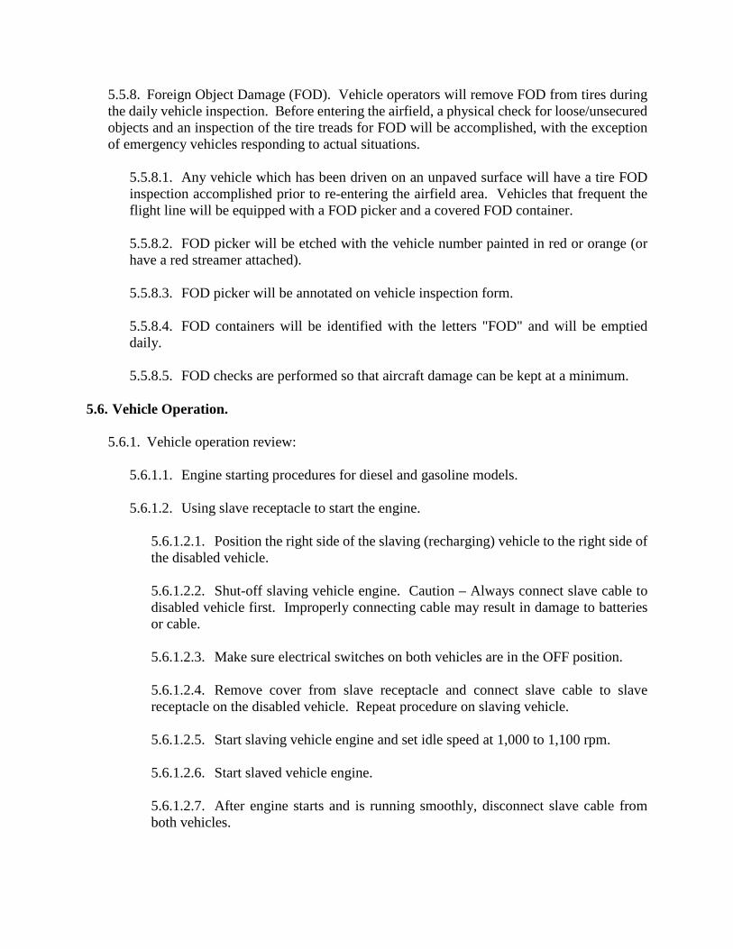
5.6.3.3. CTIS RUN FLAT Mode.
5.6.3.3.1. CTIS operation in RUN FLAT mode is limited to 10 minutes. To continue operating CTIS in RUN FLAT mode after 10 minutes, RUN FLAT mode button must be pressed again or CTIS will shut down completely. Failure to comply may result in damage to equipment. 5.6.3.3.2. CTIS is operated in RUN FLAT mode when tire(s) have been punctured, RUN FLAT mode causes CTIS to check tire pressure every 15 seconds (normal interval is every 15 minutes). If low air pressure is sensed, CTIS will supply air in wet tank to leaking tire(s) every 15 seconds.
Figure 5.11. CTIS RUN FLAT Mode.
Table 5.10. CTIS RUN FLAT Mode. Step Description 1 Press RUN FLAT mode button (1). RUN FLAT mode light (2) will illuminate
when CTIS is operating in RUN FLAT mode. 2 If operating CTIS in RUN FLAT mode is no longer required, press RUN FLAT
mode button (1) again. RUN FLAT mode light (2) will go out. 3 Change leaking tire(s) as soon as possible.
5.6.3.4. Additional Controls.

Figure 5.12. Additional Controls.
Table 5.11. Additional Controls. Control Description 1 Horn Button Sounds horn when pressed. 2 Windshield
Washer Switch Activates windshield washer when pushed in.
3 Windshield Wiper Switch
Four position switch used to operate and control the speed of the windshield wipers. Windshield wipers operate at low or high speed when switch is placed in the “I” or “II” position respectively.
4 Turn Signal/Headlight Dimmer Control
Operates turn signals and controls headlight dimming. Right turn signal and indicator will flash when control is moved up. Left turn signal and indicator will flash if control is moved down. Headlight dimming is controlled by pulling the control toward the operator. High Beam Indicator illuminates when high beam headlights are on.
5 Steering Wheel Tilt/Telescope Control
Adjusts angle and height of steering wheel.
5.6.3.5. Hydraulic Control Manifold is located on the right side of the vehicle adjacent to the toolbox. The Backup Pump forward of the toolbox is used if air is not available in the vehicle air system.

Figure 5.13. Hydraulic Control Manifold.
Table 5.12. Hydraulic Control Manifold. Control Description 1A Cab TILT Knob Allows the operator to select to raise or lower the cab. 2A SPARE TIRE Knob Allows the operator to select to raise or lower the spare tire. 3A SUSPENSION
Knob Allows the operator to raise or lower the suspension.
4A FUNCTION SELECT Knob
Selection determines which component will receive the hydraulic pressure.
5A PUMP Knob Pushing in and holding PUMP Knob will activate selected system. 6A CAB Knob Pull out and turn left to deflate cab air springs. Push and turn
knob to the right to inflate cab air springs. 1B XMSN
(Transmission) DIP STICK
Indicates oil level in the transmission.
2B NATO Receptacle Receptacle used for starting the vehicle using external power. 3B Hydraulic Reservoir
Gauge (if applicable) Only used on vehicles with a winch.
4B Engine Oil Dipstick Indicates oil level in the engine. 5B Radiator Overflow
Tank Sight Glasses Top sight glass indicates safe coolant level with the engine not running.
6B Power Steering Dipstick
Indicates oil level in the power steering reservoir.
5.6.3.6. Air/Hydraulic Power Unit is located behind the cab to the left of the spare tire. This is the pump which raises the cab, lowers the spare tire, etc. The dipstick for checking hydraulic oil level is located on the body of the pump housing.

Figure 5.14. Air/Hydraulic Power Unit.
5.6.3.7. Cargo Bed sides and tailgate may be removed and stored creating a flatbed truck. Storage is provided in compartments below the bed. (See below).
Figure 5.15. Cargo Bed.
5.6.3.8. Center stakes and rear stakes may also be removed and stored in a compartment at the front of the bed. (Requires a wrench to remove retaining bolt).

Figure 5.16. Stowage Compartments.
5.6.3.9. A ladder is available for aiding in access to the bed. It is located between the frame rails at the rear of the bed. A locking pin keeps it in the stored position. Two rectangular holes are available in the bed into which to insert the hooks on the ladder. The plugs are held in by a retaining pin under the rear of the bed.
Figure 5.17. Ladder and Locking Pin.
5.6.3.10. Pintle Hook.
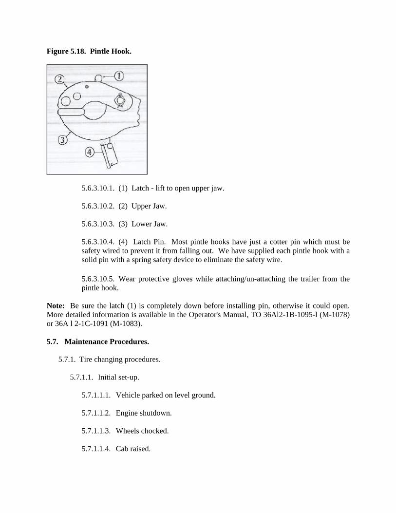
Figure 5.18. Pintle Hook.
5.6.3.10.1. (1) Latch - lift to open upper jaw. 5.6.3.10.2. (2) Upper Jaw.
5.6.3.10.3. (3) Lower Jaw.
5.6.3.10.4. (4) Latch Pin. Most pintle hooks have just a cotter pin which must be safety wired to prevent it from falling out. We have supplied each pintle hook with a solid pin with a spring safety device to eliminate the safety wire.
5.6.3.10.5. Wear protective gloves while attaching/un-attaching the trailer from the pintle hook.
Note: Be sure the latch (1) is completely down before installing pin, otherwise it could open. More detailed information is available in the Operator's Manual, TO 36Al2-1B-1095-l (M-1078) or 36A l 2-1C-1091 (M-1083). 5.7. Maintenance Procedures.
5.7.1. Tire changing procedures.
5.7.1.1. Initial set-up.
5.7.1.1.1. Vehicle parked on level ground.
5.7.1.1.2. Engine shutdown.
5.7.1.1.3. Wheels chocked.
5.7.1.1.4. Cab raised.

5.7.1.2. Tools.
5.7.1.2.1. Jack, hydraulic.
5.7.1.2.2. Wrench, socket. 5.7.1.3. Changing Lower Spare Tire.
Note: Warning – Ensure vehicle is parked on level ground before changing flat tire. Vehicle may roll. Failure to comply may result in serious injury or death to personnel.
Figure 5.19. Changing Lower Spare Tire (1 of 3).
5.7.1.3.1. Step 1. Release latch (1) on ratchet (2). 5.7.1.3.2. Step 2. Lift ratchet (2) and release strap (3).
5.7.1.3.3. Step 3. Remove strap (3) from ratchet (2).
5.7.1.3.4. Step 4. Disconnect safety chain (4) from spare tire retainer (5). Caution – Ratchet must be in the closed position before cab is lowered. Failure to comply may result in damage to equipment.

Figure 5.20. Changing Lower Spare Tire (2 of 3).
5.7.1.3.5. Step 5. Place ratchet (2) in closed position.
Figure 5.21. Changing Lower Spare Tire (3 of 3).
5.7.1.3.6. Step 6. Remove strap (3) and safety chain (4) from spare tire retainer (5). 5.7.1.3.7. Step 7. Lower cab.

Figure 5.22. Spare Tire Function Knob.
5.7.1.3.8. Step 8. Turn SPARE TIRE knob (6) to the LOWER position.
5.7.1.3.9. Step 9. Turn FUNCTION SELECT knob (7) to the SPARE TIRE position.
Note: WARNING – Tire weighs approximately 350 lbs (159 kgs). If treads of tire catch on tool box during lowering, raise tire and pull tire away from tool box and continue lowering. Use extreme care when lowering or handling tire. Failure to comply may result in injury to personnel. Use caution when lowering tire to prevent damage to CTIS wheel valve. Failure to comply may result in damage to equipment. Use backup hydraulic pump if pressing PUMP knob does not accomplish step (10).
5.7.1.3.10. Step 10. Press and hold PUMP knob (8) to lower spare tire (9) to ground.

Figure 5.23. Lower Spare Tire.
5.7.1.3.11. Step 11. Disconnect one end of the chain (10) from spare tire retainer lift arm (11). 5.7.1.3.12. Step 12. Pull chain (10) through hole in spare tire (9).
5.7.1.3.13. Step 13. Hook chain (10) to spare tire retainer lift arm (11).
Figure 5.24. Hook Chain to Retainer.

5.7.1.3.14. Step 14. Remove nut (12), two washers (13), and bolt (14) from CTIS hose (15).
Figure 5.25. Remove Nuts/Washers/Bolts.
5.7.1.4. Tire Removal. Warning – Place hydraulic jack on flat surface. Do not allow personnel under vehicle when jacking. Failure to comply may result in serious injury or death to personnel.
Figure 5.26. Tire Removal Tool Box.

5.7.1.4.1. Step 1. Remove hydraulic jack (1) and handle (2) from tool box. Note: Perform steps (2) and (3) when removing front tire.
Figure 5.27. Position Hydraulic Jack.
5.7.1.4.2. Step 2. Position hydraulic jack (1) under saddle (3) of leaf spring (4). 5.7.1.4.3. Step 3. Unscrew jack ram (5) until it touches saddle (3). Note: Perform steps (4) and (5) when removing rear tire.
5.7.1.4.4. Step 4. Position hydraulic jack (1) under inside bolt head on shock mount (6).
Figure 5.28. Position Hydraulic Jack (continued).
5.7.1.4.5. Step 5. Unscrew jack ram (5) until it touches shock mount (6).

Note: Both front and rear tires are removed the same way. Rear tire shown. Air will not escape when CTIS hose is removed from hollow wheel stud.
Figure 5.29. Removal of Bolts/Washers.
5.7.1.4.6. Step 6. Remove banjo bolt (7), two washers (8), and CTIS hose (9) from hollow wheel stud (10).
Note: Studs and lug nuts on left side of vehicle have left-hand threads. Turn lug nuts to right to loosen, and turn left to tighten. Studs and lug nuts on right side of vehicle have right-hand threads. Turn lug nuts to left to loosen, and to right to tighten.
Figure 5.30. Loosen Lug Nuts.
5.7.1.4.7. Step 7. Loosen ten lug nuts (11).

Figure 5.31. Raise Hydraulic Jack.
5.7.1.4.8. Step 8. Raise hydraulic jack (1) until tire (12) is off ground. Warning – Tire weighs approximately 350 lbs (159 kgs). Use extreme care when handling tire. Failure to comply may result in injury to personnel.
Figure 5.32. Removal of Lug Nuts.
5.7.1.4.9. Step 9. Remove ten lug nuts (11) from studs (13). Caution – Do not drag tire across studs during removal. Failure to comply may result in damage to equipment. 5.7.1.4.10. Step 10. Remove tire (12) from studs (13). Note: This step requires the aid of an assistant.
5.7.1.5. Tire Installation. Note: Steps (1) through (5) require the aid of an assistant.
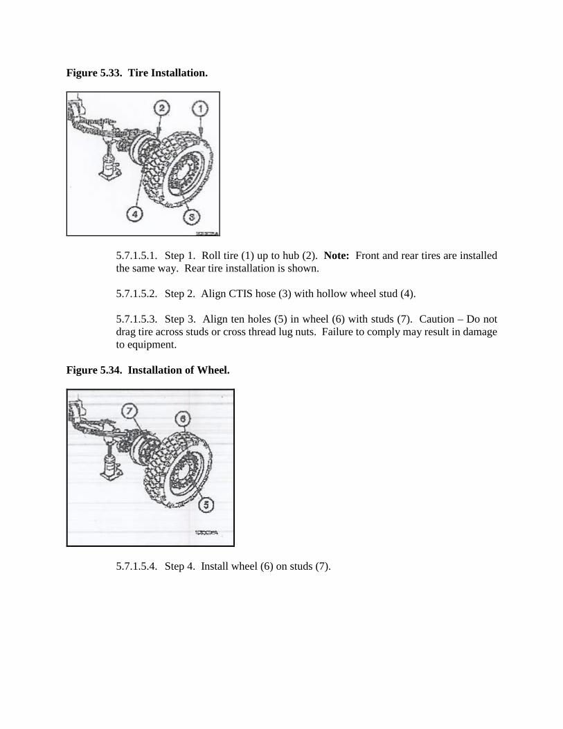
Figure 5.33. Tire Installation.
5.7.1.5.1. Step 1. Roll tire (1) up to hub (2). Note: Front and rear tires are installed the same way. Rear tire installation is shown. 5.7.1.5.2. Step 2. Align CTIS hose (3) with hollow wheel stud (4).
5.7.1.5.3. Step 3. Align ten holes (5) in wheel (6) with studs (7). Caution – Do not drag tire across studs or cross thread lug nuts. Failure to comply may result in damage to equipment.
Figure 5.34. Installation of Wheel.
5.7.1.5.4. Step 4. Install wheel (6) on studs (7).

Figure 5.35. Tightening Sequence.
Note: Warning – Notify Unit Maintenance that lug nuts must be tightened to 425-475 lb-ft (576-644 N m) as soon as possible. Tire may come loose if lug nuts are not tightened to proper torque. Failure to comply may result in serious injury or death to personnel.
5.7.1.5.5. Step 5. Install ten lug nuts (8) on studs (7) in sequence shown.
Note: Studs and lug nuts on left side of vehicle have left-hand threads. Turn lug nuts to right to loosen, and to left to tighten. Studs and lug nuts on right side of vehicle have right-hand threads. Turn lug nuts to left to loosen, and to right to tighten.
5.7.1.5.6. Step 6. Lower vehicle to ground with hydraulic jack (9).
Figure 5.36. Position of Hydraulic Jack.
5.7.1.5.7. Step 7. Remove hydraulic jack (9) and handle (10) from vehicle.

Figure 5.37. Toolbox.
5.7.1.5.8. Step 8. Stow hydraulic jack (9) and handle (10) in toolbox.
Figure 5.38. Installation of Nuts.
5.7.1.5.9. Step 9. Install CTIS hose (3) on hollow wheel stud (4) with two washers (11) and banjo bolt (12). Caution – Do not over tighten banjo bolt when installing CTIS hose on hollow wheel stud. Failure to comply may result in damage to equipment.

5.7.1.6. Tire Stowage. WARNING: Handle tire with care. Tire may have exposed broken metal cords or sharp debris in it. Failure to comply may result in injury to personnel. Tire weighs approximately 350lbs (159kgs). Use extreme care when handling tire. Failure to comply may result in injury to personnel.
Figure 5.39. Installation of Lug Nuts.
5.7.1.6.1. Step 1. Install bolt (1), two washers (2) and nut (3) in CTIS hose (4). 5.7.1.6.2. Step 2. Roll flat tire (5) under center of spare tire retainer lift arm (6).
5.7.1.6.3. Step 3. Disconnect one end of chain (7) from spare tire retainer lift arm (6). Note: The valve on tire must be positioned to the front of vehicle and at the 6 o'clock position. Flat tire should be straight up and down when installing chain through lug hole.
Figure 5.40. Hook Tire to Retainer.
5.7.1.6.4. Step 4. Route chain (7) through uppermost lug hole (8) in wheel (9).

5.7.1.6.5. Step 5. Connect chain (7) to spare tire retainer lift arm (6). Caution – Use caution when raising tire to prevent damage to CTIS valve. Failure to comply may result in damage to equipment.
Figure 5.41. Raise Tire – Tool Box.
5.7.1.6.6. Step 6. Raise cab. 5.7.1.6.7. Step 7. Turn SPARE TIRE knob (10) to the RAISE Position.
5.7.1.6.8. Step 8. Turn FUNCTION SELECT knob (11) to the SPARE TIRE position.
5.7.1.6.9. Caution – Tire must be stowed against back frame of spare tire retainer (for all models except Air Drop vehicles). Failure to comply may result in damage to equipment.
Note: Use backup hydraulic pump (para 2-41) if pressing PUMP knob does not accomplish step (9).

Figure 5.42. Pump Knob.
5.7.1.6.10. Step 9. Press and hold PUMP knob (12) to raise spare tire retainer lift arm (6) to the stowed position.
Note: Caution – Tread engagers must be in slots of tire treads. A loose strap will allow tire to move causing chafing of strap and possible loss of tire. Failure to comply may result in damage to equipment. Tread engagers must not be snug at installation for proper fit, but strap must have a tight fit. Failure to comply may result in damage to equipment.

Figure 5.43. Tread Engager.
5.7.1.6.11. Step 10. Position tread engager (13) in third tread (14), tread engager (15) in sixth tread (16), and tread engager (17) in ninth tread (18). 5.7.1.6.12. Step 11. Connect strap (19) to spare tire retainer (20).
Figure 5.44. Strap through Ratchet.
5.7.1.6.13. Step 12. Feed other end of strap (19) through ratchet (21). Caution – Ensure that strap is wrapped around ratchet at least three complete wraps after tightening. Failure to comply may result in damage to equipment.

5.7.1.6.14. Step 13. Tighten strap (19) around flat tire (5) with ratchet (21) and close latch (22).
Figure 5.45. Safety Chain.
5.7.1.6.15. Step 14. Connect safety chain (23) to spare tire retainer (20). Caution – Ensure that safety chain is loose. If safety chain is tight then strap is not tight enough. Failure to comply may result in damage to equipment. 5.7.1.6.16. Step 15. Route other end of safety chain (23) through flat tire (5) and connect to spare tire retainer (20).
Figure 5.46. Safety Chain (continued).
5.7.1.6.17. Step 16. Lower cab.

5.7.2. Self Recovery Winch (SRW) Guidelines for light medium tactical vehicle (LMTV) (if applicable).
5.7.2.1. The SRW is located aft of the fuel tank on the passenger side, winch is for forward or aft operation and may be used 15 degrees left or right off centerline as any additional bend will affect pulling capability, winch operation and can led to damage or injury if not properly followed. 5.7.2.2. Safety:
5.7.2.2.1. Winch use is extremely hazardous and should only be used by qualified and safety minded personnel.
5.7.2.2.2. Mandates that the winch will be fully extended, checked for fraying, condition, and proper operation/movement bi-annually (i.e. summer and winter ops changeover) and before any actual recovery operations take place.
5.7.2.3. Spooling Cable to Front of Vehicle.
Note: Warning – Wear heavy leather-palmed work gloves when handling cable. Cables can become frayed or contain broken wires. Never let moving cable slide through hands, even when wearing gloves. Failure to comply may result in injury to personnel.
5.7.2.3.1. Step 1. Shut down engine (WP 0019). 5.7.2.3.2. Step 2. Remove retaining pin (1), pin (2), and roller (3) from rear roller support (4).
Figure 5.47. Roller Support.
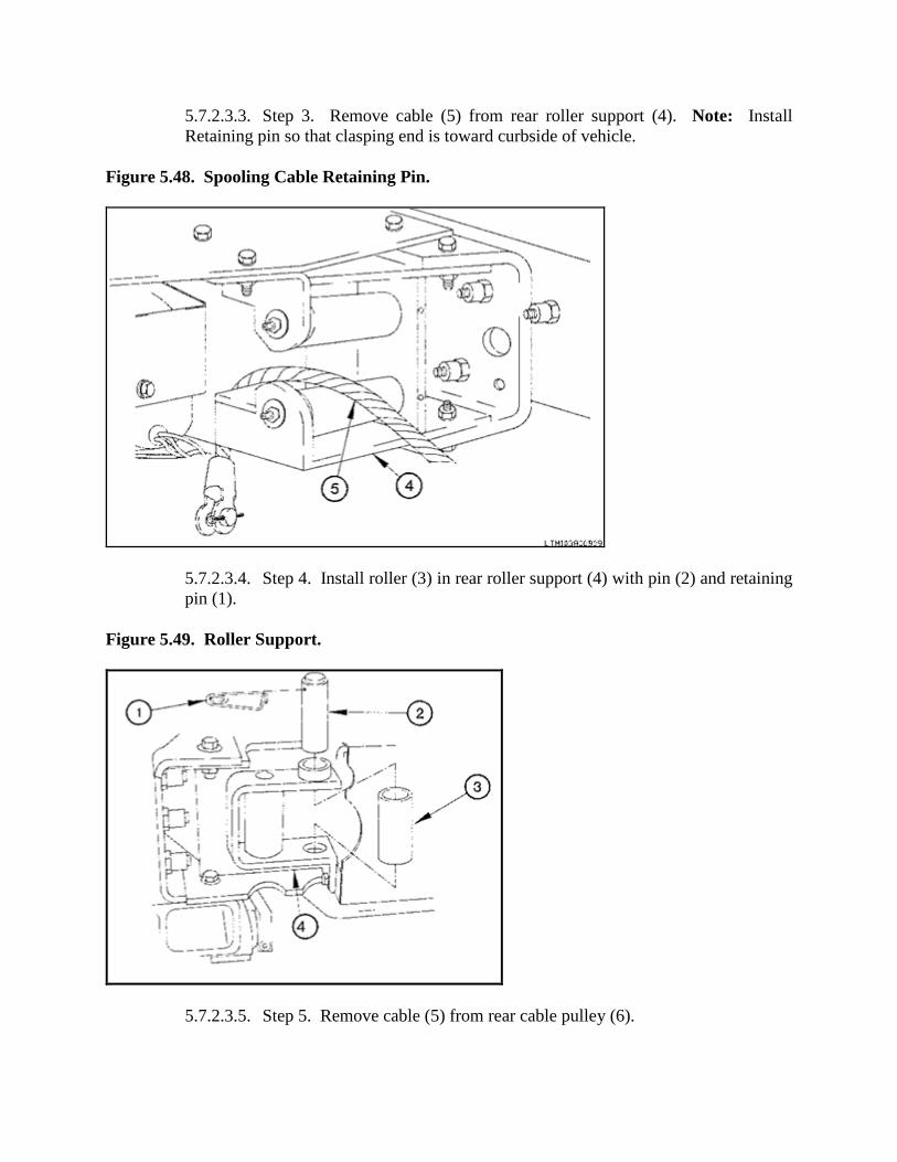
5.7.2.3.3. Step 3. Remove cable (5) from rear roller support (4). Note: Install Retaining pin so that clasping end is toward curbside of vehicle.
Figure 5.48. Spooling Cable Retaining Pin.
5.7.2.3.4. Step 4. Install roller (3) in rear roller support (4) with pin (2) and retaining pin (1).
Figure 5.49. Roller Support.
5.7.2.3.5. Step 5. Remove cable (5) from rear cable pulley (6).

Figure 5.50. Cable Pulley.
5.7.2.3.6. Step 6. Remove cable (5) from rear cable guide (7) on 15K SRW (8).
Figure 5.51. Cable Position.
5.7.2.3.7. Step 7. Position cable (5) toward front of vehicle. 5.7.2.3.8. Step 8. Install cable (5) through front cable guide (9) on l5K SRW (8).

Figure 5.52. Install Cable.
5.7.2.3.9. Step 9. Install cable (5) through cable guide (10) behind fuel tank (11).
Figure 5.53. Install Cable (continued).
5.7.2.3.10. Step 10. Install cable (5) through front cable pulley (12).

Figure 5.54. Retaining Pin.
5.7.2.3.11. Step 11. Remove retaining pin (13), pin (14), and roller (15) from front roller support (16).
Figure 5.55. Remove Headlight Bracket.
5.7.2.3.12. Step 12. Install cable (5) through front roller support (16). Note: Install retaining pin so that clasping end is toward curbside of vehicle.
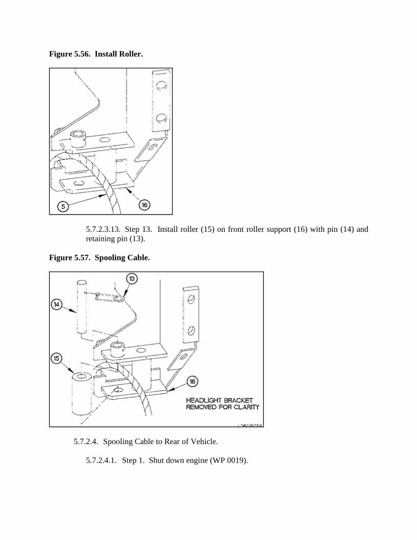
Figure 5.56. Install Roller.
5.7.2.3.13. Step 13. Install roller (15) on front roller support (16) with pin (14) and retaining pin (13).
Figure 5.57. Spooling Cable.
5.7.2.4. Spooling Cable to Rear of Vehicle.
5.7.2.4.1. Step 1. Shut down engine (WP 0019).

Figure 5.58. Headlight Bracket Retaining Pin.
5.7.2.4.2. Step 2. Remove retaining pin (13), pin (14), and roller (15) from front roller support (16). Warning – Wear heavy leather-palmed work gloves when handling cable. Cables can become frayed or contain broken wires. Never let moving cable slide through hands, even when wearing gloves. Failure to comply may result in injury to personnel. 5.7.2.4.3. Step 3. Remove cable (5) from front roller support (16). Note: Install retaining pin so that clasping end is toward curbside of vehicle. 5.7.2.4.4. Step 4. Install roller (15) on front roller support (16) with pin (14) and retaining pin (13).
Figure 5.59. Remove Cable.
5.7.2.4.5. Step 5. Remove cable (5) from front cable pulley (12).

Figure 5.60. Cable Pulley.
5.7.2.4.6. Step 6. Remove cable (5) from cable guide (10) behind fuel tank (11).
Figure 5.61. Front Cable Guide.
5.7.2.4.7. Step 7. Remove cable (5) from front cable guide (9) on l5K SRW (8).

Figure 5.62. Position Cable.
5.7.2.4.8. Step 8. Position cable (5) toward rear of vehicle. 5.7.2.4.9. Step 9. Install cable (5) through rear cable guide (7) on 15K SRW (8).
Figure 5.63. Install Cable.
5.7.2.4.10. Step 10. Install cable (5) through rear cable pulley (6).

Figure 5.64. Rear Roller Support.
5.7.2.4.11. Step 11. Remove retaining pin (1), pin (2), and roller (3) from rear roller support (4).
Figure 5.65. Rear Roller Support (continued).
5.7.2.4.12. Step 12. Install cable (5) through rear roller support (4).

Figure 5.66. Rear Roller Support (continued).
5.7.2.4.13. Step 13. Install roller (3) in rear roller support (4) with pin (2) and retaining pin (1). Warning – Ensure line pull does not exceed capacity of 15K SRW. Failure to comply may result in serious injury or death to personnel.
Note: Caution – Ensure that supply valve and return valve on M1083A1P2 are open before operating hydraulic equipment. Failure to comply may result in damage to equipment. Figure 5.67. Install Roller with Pin.
5.7.2.5. 15K SRW Operation.
5.7.2.5.1. Step 1. Shut down engine (WP 0019).

5.7.2.5.2. Warning – There must always be at least five wraps of cable on 15K SRW. If load is applied with less than five wraps of cable on 15K SRW, cable may come loose on drum. Failure to comply may result in serious injury or death to personnel.
Note: Caution – Do not attempt to pull load over 15K SRW capacity. Failure to comply may result in damage to equipment.
5.7.2.5.3. SRW operation is the same for the front and rear. Front operation is shown. 5.7.2.5.4. Step 2. Position 15K SRW clutch control lever (17) to DISENGAGED.
5.7.2.5.5. Wear heavy leather –palmed work gloves when handling cable. Cables can become frayed or contain broken wires. Never let moving cable slide through hands, even when wearing gloves. Failure to comply may result in injury to personnel.
Note: Caution – Do not attach cable to any object more than approximately 15 degrees away from a straight 15K SRW pull. Failure to comply may result in damage to equipment. Figure 5.68. Clutch Control Lever.
5.7.2.5.6. Step 3. Pull out cable (5) and attach to secure object. 5.7.2.5.7. Warning – Keep all personnel clear of area when tension is on cable. Failure to comply may result in serious injury or death to personnel.

Figure 5.69. Cable Attach to Object.
5.7.2.5.8. Step 4. Position 15K SRW clutch control lever (17) to ENGAGED. 5.7.2.5.9. Step 5. Start engine (WP 0019).
Figure 5.70. 15K Self Recovery Winch.
5.7.2.5.10. Step 6. Position PTO switch (18) to on. 5.7.2.5.11. Step 7. Position winch switch (19) to on.

5.7.2.5.12. Step 8. Hold WINCH IN/OUT switch (20) in the WINCH IN position until vehicle is recovered.
5.7.2.5.13. Step 9. Release WINCH IN/OUT switch (20).
5.7.2.5.14. Step 10. Pull out PARKING BRAKE control (21).
Figure 5.71. Parking Brake Control.
5.7.2.5.15. Step 11. Remove cable (5) from secure object.

Figure 5.72. Reel Cable.
5.7.2.5.16. Step 12. Hold WINCH IN/OUT switch (20) in the WINCH IN position to reel in cable (5) until cable socket (22) contacts rollers (3).
Figure 5.73. Reel Cable (continued).
5.7.2.5.17. Step 13. Position winch switch (19) to off. 5.7.2.5.18. Step 14. Position PTO switch (18) to off. 5.7.2.5.19. Step 15. Shut down engine (WP 0019).

Figure 5.74. Position Switch.
5.7.3. Rigging. Rigging is applying wire rope in various tackle combinations to raise or move loads. Rigging involves installing the necessary equipment to use the available effort (AE), and it may or may not produce MA.
5.7.3.1. Rigging Fundamentals.
5.7.3.1.1. Fall line.
5.7.3.1.1.1. A fall line is the winch line that runs from the source of effort to the first block in the tackle. 5.7.3.1.1.2. There is only one fall line in a simple tackle system. The amount of force that must be exerted on the fall line relative to the AE must be considered in every problem.
5.7.3.1.1.3. The fall line force must be less than the capacity of the effort to accomplish the recovery.

Figure 5.75. Terminology of Simple Tackle.
5.7.3.1.2. Return line.
5.7.3.1.2.1. A return line is a winch line rigged between the block or the winch line from the sheave of a block to the point where the end of the line is attached. This force is always the same as the fall line force.
5.7.3.1.3. Dead line.
5.7.3.1.3.1. A dead line is a line used to attach blocks or other equipment to the load or to an anchor. To determine the dead line force, multiply the fall line force by the highest number of winch lines supported by the dead line.
5.7.3.1.4. Fleet angle.
5.7.3.1.4.1. Achieving even winding of the winch cable on the drum is important for wire rope life and winch operations. This is best accomplished by working with the proper fleet angle. 5.7.3.1.4.2. Figure 5.76. displays the wire rope running from a fixed sheave, over floating sheaves, and then onto the surface of a smooth drum. The fleet angle is defined as the included angle between two lines.
5.7.3.1.4.2.1. One line is drawn through the middle of the fixed sheave and the drum and perpendicular to the axis of the drum. 5.7.3.1.4.2.2. A second line is drawn from the flange of the drum to the base of the groove in the fixed sheave.

Figure 5.76. Fleet Angle.
5.7.3.1.4.3. There are left and right fleet angles, measured to the left and right of the centerline of the sheave. The fleet angle should be restricted when wire rope passes over a fixed sheave and onto a drum. 5.7.3.1.4.4. For the most efficient method and best service, the angle should not exceed 1½ degrees, for most vehicles. Refer to the equipment operator’s manual for specific information on fleet angles.
Note: Although many vehicles have winches that can safely operate at higher fleet angles, maximum stability and performance is achieved at lesser fleet angles.
5.7.3.2. Mechanical Advantage (MA) of tackle.
5.7.3.2.1. MA is needed whenever the load resistance is greater than the AE. The amount of MA needed is estimated by dividing the load resistance by the AE. The MA of any simple tackle system is equal to the number of winch lines supporting the load or the number of winch lines that become shorter as power is applied to the winch (Figure 5.77.). The lines can be attached directly or indirectly through a block.

5.7.3.2.2. Placement of the block is critical to gaining MA. The block must be attached to the movable load and effort applied in the opposite direction to divide the effort equally over the two lines. The arc over the lines indicates lines that support the load (Figure 5.77.).
Note: The 1-to-1 ratio shown has an arc over only one line indicating the block is simply changing the direction of effort. No MA is gained in this configuration.
Figure 5.77. Winch Line(s) Mechanical Advantage.
5.7.3.3. Determine Line Forces: 5.7.3.3.1. The following example shows how to compute various line forces. A disabled vehicle had a load resistance of 14 tons (28,000 pounds). The AE is a winch with a maximum capacity of 5 tons (10,000 pounds). What MA must be rigged to recover this vehicle? What are the line forces?

Figure 5.78. Determine Line Forces.

Figure 5.79. 4-to-1 Mechanical Advantage.
Note: If field expedient slings are used as deadlines, refer to FM 5-125 to determine sling leg forces. Field expedient slings are considered slings that are constructed using materiel not part of the recovery vehicle’s BII.
5.7.3.4. Methods of Rigging: The rigging techniques used depend on terrain, the type of vehicle, and the distance between the recovery vehicle and the disabled vehicle. Manpower, backup, and lead methods for rigging techniques are discussed below.
5.7.3.4.1. Manpower method. The manpower method is used when the winch cable and other rigging equipment are lightweight and can be carried easily by the crewmembers to where they are needed. This method depends completely on Soldier manpower.
5.7.3.4.2. Backup method. The backup method is used when the recovery vehicle can be safely positioned within 20 to 25 feet of the disabled vehicle.
5.7.3.4.2.1. Pull out enough main winch cable to attach to the disabled vehicle.
5.7.3.4.2.2. Place the main winch snatch block in the loop of the cable and attach the block to the disabled vehicle.
5.7.3.4.2.3. Back up the recovery vehicle, allowing the main winch cable to be spooled from the winch drum until sufficient cable is removed to obtain maximum winch capacity.
5.7.4. Cab Raising/Lowering Guidelines for the LMTV (if applicable).

5.7.4.1. Raising/lowering cab. Raising/lowering the cab should only be performed by qualified and safety minded personnel before procedure.
Note: Warning – Engine compartment and accessories may be extremely hot when engine is running or has been running recently. Use caution around engine when cab is raised. Failure to comply may result in injury to personnel. Engine compartment contains a partially exposed fan blade. Use extreme caution around front of engine. Failure to comply may result in injury to personnel.
5.7.4.2. Raising Cab. 5.7.4.2.1. Step 1. Remove quick release pin (1) from switch box cover (2).
5.7.4.2.2. Step 2. Open switch box cover (2) on electric hydraulic switch box (3).
Figure 5.80. Raising Cab Switch Box.
5.7.4.2.3. Step 3. Position NORMAL OPERATION/AIR TRANSPORT switch (4) to NORMAL OPERATION. Note: Switches must be held in operating position while conducting the raise cab function.

Figure 5.81. Raising Cab Switch Box (continued).
5.7.4.2.4. Step 4. Position and hold CAB switch (5) to RAISE until cab is fully raised.
5.7.4.2.4.1. Warning – Never raise cab while occupied or when parked uphill on a steep grade. Failure to comply may result in serious injury or death to personnel. Ensure both doors are securely closed before cab is raised.
5.7.4.2.4.2. Do not allow personnel near cab when cab is being raised. Failure to comply may result in serious injury or death to personnel or damage to equipment.
5.7.4.2.4.3. Remove all loose objects from cab before raising the cab. Failure to comply may result in damage to equipment. Cab height is higher than normal when raised. Ensure area above and in front of cab is adequate before raising the cab.
Note: Use backup hydraulic pump if temperature is below -25° F (-32° C) or if pressing CAB switch does not accomplish step 4.

Figure 5.82. Raising Cab Switch Box (continued).
5.7.4.3. Lowering Cab. 5.7.4.3.1. Step 1. Position NORMAL OPERATION/AIR TRANSPORT switch (4) to NORMAL OPERATION.
Note: Warning – Ensure both doors are securely closed before cab is lowered. Do not allow personnel near cab when cab is being lowered. Failure to comply may result in serious injury or death to personnel or damage to equipment.

Figure 5.83. Switch Box.
5.7.4.3.2. Step 2. Position and hold CAB switch (5) to LOWER until cab is fully lowered.
Note: Switches must be held in operating position while conducting the various functions. If the NORMAL OPERATION/AIR TRANSPORT switch is on air transport mode, the cab ride height limit switch is deactivated and the rear leveler cylinders will completely retract. When the NORMAL OPERATION/AIR TRANSPORT switch is positioned in NORMAL OPERATION, the cab will raise automatically to its preset ride height when the master power is ON or the engine is running. If the ignition is on while lowering the cab, it will lower but will automatically raise up to its preset ride height. The rear cylinders will not stay lowered completely. Use backup hydraulic pump if temperature is below -25° F (-32° C) or if pressing CAB switch does not accomplish step 2.

Figure 5.84. Switch Box (continued).
5.7.4.3.3. Step 3. Check button (6) position to confirm cab is latched.
5.7.4.3.4. Warning – Cab hydraulic latch must be locked before driving vehicle. Failure to comply may result in serious injury or death to personnel or damage to equipment.
Note: Button on right end of cab hydraulic latch shows status of latch. Button pressed in shows cab is latched. Button out shows cab is not latched.

Figure 5.85. Latch Cab.
5.7.4.3.5. Step 4. Close switch box cover (2) on electric hydraulic switch box (3).
5.7.4.3.6. Step 5. Install quick release pin (1) in switch box cover (2).
Figure 5.86. Switch Box (continued).

Section 6—EXPLANATION AND DEMONSTRATION. 6.1. Instructor’s Preparation.
6.1.1. Establish a training location. 6.1.2. Obtain appropriate vehicle operator’s manual. 6.1.3. Schedule/reserve a vehicle. 6.1.4. Ensure trainee completes AF Form 171.
6.2. Safety Procedures and Equipment.
6.2.1. The following safety items should be followed by both the instructor and trainee.
6.2.1.1. Chock wheel (if required) when oversized cargo M-series truck is parked. 6.2.1.2. Remove all jewelry and identification tags. 6.2.1.3. Personal protective equipment and equipment items.
6.2.1.3.1. Safety steel-toed boots must be worn. 6.2.1.3.2. Gloves will be worn during cargo loading and unloading. 6.2.1.3.3. First aid kit. 6.2.1.3.4. Raingear, cold weather gear, etc. 6.2.1.3.5. Reflective belt during hours of reduced visibility or on the flightline.
6.2.1.3.6. Hearing protection.
6.2.1.4. Walk around vehicle to become familiar with and to familiarize and the trainee with all warning labels and signs. 6.2.1.5. Ensure trainee wears seatbelts. 6.2.1.6. Properly adjust driver’s seat and all mirrors, if available. 6.2.1.7. Throughout demonstration, practice oversized cargo M-series truck safety.
6.2.2. Practice basic RM process during demonstration:
6.2.2.1. Identify hazards.

6.2.2.2. Assess hazards. 6.2.2.3. Develop controls and make decisions. 6.2.2.4. Implement controls. 6.2.2.5. Supervise and evaluate.
6.3. Operator Maintenance Demonstration.
6.3.1. With trainee, accomplish vehicle inspection using AF Form 1800. The vehicle inspection will follow the seven-step method as described in Attachment 4. An inspection guide (Attachment 2) can be used to ensure all areas of the tractor and trailer are covered in addition to the “Operation Demonstration” guidelines provided below.
6.4. Operation Demonstration.
6.4.1. Throughout demonstration:
6.4.1.1. Allow for questions. 6.4.1.2. Repeat demonstrations as needed.
6.4.2. For all oversized cargo M-series trucks, within the training area, demonstrate and explain the following. Note: Use information contained on the data plate and/or the operator’s manual.
6.4.2.1. Specific oversized cargo M-series truck capacities: Explain parking brake as they apply to oversized cargo M-series truck being used. 6.4.2.2. Oversized cargo M-series truck controls.
6.4.2.2.1. Shifting pattern.
6.4.2.2.2. Overdrive.
6.4.2.3. Point out the items to be inspected during operations.
6.4.2.3.1. Instruments. 6.4.2.3.2. Air pressure gauge (if the vehicle has air brakes). 6.4.2.3.3. Temperature gauges. 6.4.2.3.4. Pressure gauges.

6.4.2.3.5. Ammeter/voltmeter. 6.4.2.3.6. Mirrors. 6.4.2.3.7. Tires. 6.4.2.3.8. Cargo, cargo covers.
6.4.3. Demonstrate the following oversized cargo M-series truck operations (use spotter when backing).
6.4.3.1. Forward stop (see following example for boundary setup).
6.4.3.1.1. Drive forward between the two rows. 6.4.3.1.2. Bring vehicles to a complete stop as close to the boundary.
6.4.3.2. Backing.
6.4.3.2.1. Always use a spotter when backing. 6.4.3.2.2. The spotter and operator must maintain visual contact at all times. If visual contact is lost, the operator must immediately stop the vehicle.
6.4.3.2.3. See AFMAN 24-306 for additional guidance on standard AF spotter hand signals and safety.
6.4.3.3. Parking. 6.4.3.4. Right turn (see following example for boundary set-up).
6.4.3.4.1. Drive forward and make a right turn around a cone.
6.4.3.4.2. Bring right rear wheel(s) of the vehicle as close to the base of the cone as possible without hitting it.
6.4.4. Demonstrate securing cargo (if applicable to vehicle type). 6.4.5. Demonstrate towing operation/winch operation (if applicable).
6.4.6. With the oversized cargo M-series truck, demonstrate driving on a road course.
6.4.6.1. Turns (Left/Right). 6.4.6.2. Intersections.

6.4.6.3. Urban/rural straight. 6.4.6.4. Expressway. 6.4.6.5. Start/stop. 6.4.6.6. Curves. 6.4.6.7. Upgrades/Downgrades. 6.4.6.8. Local off-road driving. Note: course must be approved by Security Forces and the Installation Occupational Safety Office.
6.4.7. Show trainee the after operation inspection and report.
6.4.7.1. Ensure vehicle is cleaned. 6.4.7.2. Cargo straps and chains are properly stowed. 6.4.7.3. Refuel vehicle. 6.4.7.4. Following manufacturer’s shut-down procedures. 6.4.7.5. Park.
6.4.7.5.1. Apply brakes.
6.4.7.5.2. Place transmission in neutral (park or an automatic).
6.4.7.6. Perform a walk around inspection. 6.4.7.7. Annotate any discrepancies found on AF Form 1800.
6.4.8. Conclude by allowing time for questions and any requested re-demonstrations. Section 7—TRAINEE PERFORMANCE AND EVALUATION 7.1. Trainee Performance.
7.1.1. Instructor will:
7.1.1.1. Ensure safety at all times. Note: Stop training when safety items are violated. Proceed only when the trainee fully understands how to avoid repeating the safety infraction(s).

7.1.1.1.1. Chock wheel (if required) when oversized cargo M-series truck is parked. 7.1.1.1.2. Remove all jewelry and identification tags.
Note: If available, mark vehicle with magnetic sign indicating “Driver-in-Training” or “Trainee Operator.”
7.1.1.2. Personal protective equipment (PPE) and other items:
7.1.1.2.1. Safety steel-toed boots must be worn. 7.1.1.2.2. Gloves will be worn during cargo loading and unloading. 7.1.1.2.3. First aid kit. 7.1.1.2.4. Reflective belt during hours of reduced visibility or on the flightline. 7.1.1.2.5. Raingear, cold weather gear, etc.
7.1.1.2.6. Hearing protection.
7.1.1.3. Pay particular attention to the cautions and warnings listed in the operator's manual. 7.1.1.4. Ensure trainee wears seatbelts. 7.1.1.5. Properly adjust driver’s seat and all mirrors. 7.1.1.6. Oversized cargo M-series truck safety items/procedures. 7.1.1.7. Ensure the driver is aware of driving situations he/she is to perform. 7.1.1.8. Conduct during/after-action reviews with the trainee (demonstration may need to be re-accomplished).
7.1.2. Trainee Performance.
7.1.2.1. Conduct operator maintenance (have trainee explain items being inspected). Note: Allow trainee to use Attachment 2 as a guide while performing inspection.
7.1.2.1.1. Pre-inspection.
7.1.2.1.2. During-inspection. 7.1.2.2. Ensure AF From 1800 is properly documented.

7.1.2.2.1. Establish a road course that will have the following: (if the course does not have one of the following, then the trainee should be able to explain the correct driving techniques).
7.1.2.2.1.1. Turns (Left/Right).
7.1.2.2.1.2. Lane change maneuvers.
7.1.2.2.1.3. Intersections.
7.1.2.2.1.4. Urban/rural straight.
7.1.2.2.1.5. Start/stop.
7.1.2.2.1.6. Curves.
7.1.2.2.1.7. Upgrades/Downgrades.
7.1.2.2.1.8. Backing.
7.1.2.2.1.8.1. Serve as the trainee’s spotter, or if available, have another trainee be the spotter.
7.1.2.2.1.9. Parking. 7.1.2.2.1.10. Local off-road driving. Note: Course must be approved by Security Forces and the Installation Occupational Safety Office.
7.1.2.2.2. Continue until trainee can show proficiency in operating.
7.1.2.3. Have trainee practice the oversized cargo M-series truck operations listed below (use spotter when backing) until they can safely and efficiently perform.
7.1.2.3.1. Securing cargo, have trainees secure different types of cargo, if applicable to vehicle type. 7.1.2.3.2. Demonstrate towing operation/winch operation (if applicable).
7.1.2.4. Perform post-operation inspection.
7.1.2.4.1. Ensure vehicle cleaned.
7.1.2.4.2. Cargo straps and chains are properly stowed.
7.1.2.4.3. Refueled.

7.1.2.4.4. Following manufacturer’s shut-down procedures.
7.1.2.4.5. Park.
7.1.2.4.6. Apply brakes.
7.1.2.4.7. Place transmission in neutral (park or an automatic).
7.1.2.5. Perform a walk around inspection. 7.1.2.6. Report any discrepancies found on AF Form 1800.
7.2. Performance Evaluation.
7.2.1. Trainee will perform performance evaluation found in Attachment 3.
7.2.1.1. Instructor and trainee will review Attachment 3.
7.2.1.2. Instructor will answer trainee’s questions.
Note: If available, mark vehicle with magnetic sign indicating “Driver-in-Training” or “Trainee Operator”.
7.2.2. Instructor will:
7.2.2.1. Ensure safety at all times.
7.2.2.1.1. Place wheel chocks (if required) when oversized cargo M-series truck is parked,
7.2.2.1.2. Remove all jewelry and identification tags.
7.2.2.2. PPE and other items.
7.2.2.2.1. Safety steel-toed boots must be worn.
7.2.2.2.2. Gloves will be worn during cargo loading and unloading. 7.2.2.2.3. First aid kit.
7.2.2.2.4. Reflective belt during hours of reduced visibility or on the flightline.
7.2.2.2.5. Hearing protection.
7.2.2.3. Pay particular attention to the cautions and warnings listed in the operator's manual.

7.2.2.4. Ensure trainee wears seatbelts.
7.2.2.5. Properly adjust driver’s seat and all mirrors (if available).
7.2.2.6. Oversized cargo M-series truck safety items/procedures.
7.2.3. Explain driving techniques. 7.2.4. Establish a road course that will have the following: (if the course does not have one of the following, then the trainee should be able to explain the correct driving techniques).
7.2.4.1. Establish a road course that will have the following: (if the course does not have one of the following, then the trainee should be able to explain the correct driving techniques).
7.2.4.1.1. Turns (Left/Right).
7.2.4.1.2. Lane change maneuvers.
7.2.4.1.3. Intersections.
7.2.4.1.4. Urban/rural straight.
7.2.4.1.5. Curves.
7.2.4.1.6. Upgrades/Downgrades.
7.2.4.1.7. Backing.
7.2.4.1.8. Parking.
7.2.4.1.9. Local off-road driving. Note: Course must be approved by Security Forces and the Installation Occupational Safety Office.
7.2.5. Ensure the driver is aware of driving situations. 7.2.6. Conduct after-action reviews with the trainee. 7.2.7. Trainee is not allowed any instructor assists to pass performance evaluation. 7.2.8. Evaluation checklist provided in Attachment 3. 7.2.9. Retraining; retrain No-Go’s.
7.2.9.1. Re-demonstrate “No-Go” items.

7.2.9.2. Have trainee re-perform until they show proficiency in operating, critique weaknesses as observed.
7.2.9.3. Re-evaluate.

Attachment 1
GLOSSARY OF REFERENCES AND SUPPORTING INFORMATION References AFI 24-301, Ground Transportation, 1 November 2018 AFMAN 24-306, Operation of Air Force Government Motor Vehicles, 9 December 2016 AFPAM 90-803, Risk management (RM) Guidelines and Tools, 11 February 2013 AFI 91-203, Air Force Consolidated Occupational Safety Instruction, 12 June 2012 Adopted Forms AF Form 171, Request for Driver’s Training and Addition to U.S. Government Drivers, 1 November 2018 AF Form 847, Recommendation for Change in Publication AF Form 1800, Operator’s Inspection Guide and Trouble Report Abbreviations and Acronyms AE—Available Effort AF—Air Force AFI—Air Force Instruction AFIMSC—Air Force Installation and Mission Support Center AFMAN—Air Force Manual AFQTP—Air Force Qualification Training Plan BO—Blackout CTIS—Central Tire Inflation System ECU—Electronic Control Unit FOD—Foreign Object Damage IAW—In Accordance With KPH—Kilometers Per Hour LMTV—Light Medium Tactical Vehicle MA—Mechanical Advantage MPH—Miles Per Hour PPE—Personal Protective Equipment PSI—Pounds Per Square Inch PTO—Power Take-off RM—Risk Management RPM—Revolutions Per Minute SRW—Self Recovery Winch TO—Technical Order VCNCO—Vehicle Control Non Commissioned Officer VCO—Vehicle Control Officer

Attachment 2
OVERSIZED CARGO M-SERIES TRUCK INSPECTION GUIDE GENERAL STEP 1. VEHICLE OVERVIEW Paperwork
• AF Form 1800 • Discrepancy Correction Complete (VM Annotation)
Vehicle Approach • Damage • Vehicle Leaning • Fresh Leakage of Fluids • Hazards Surrounding Vehicle
INTERNAL STEP 2. ENGINE COMPARTMENT Leaks/hoses/Electrical Wiring Insulation Oil Level Coolant Level Power Steering Fluid Windshield Washer Fluid Battery Fluid Level, Connections & Tie-downs Automatic Transmission Fluid Level Engine Compartment Belts STEP 3. ENGINE START/CAB CHECK (LEFT/FRONT/RIGHT) Safe Start Gauges
• Oil Pressure Gauge • Air Pressure Gauge • Temperature Gauge (Coolant/Engine Oil) • Ammeter/Voltmeter
Warning Lights & Buzzers Mirrors & Windshield Wipers/Washers Emergency & Safety Equipment
• Red Reflective Triangles • Properly Charged & Rated Fire Extinguisher • Optional (Chains/Tire Changing Equip, Emergency Phone List)

3B – Lights/Reflectors/Reflector Tape Condition (Front/Sides/Rear) (Dash Indicators for:)
• Left Turn Signal • Right Turn Signal • Four-Way Emergency Flashers • High Beam Headlight • Clearance Lights
(Reflective Clean & Functional Light & Reflector Checks Include:) • Headlights • Taillights • Backing Lights • Turn Signals • Four-Way Flashers • Brake Lights • Red Reflectors & Amber Reflectors • Reflective Tape Condition
Horn Heater/Defroster Brakes
• Parking Brake Check • Hydraulic Brake Check • Air Brake Check (if equipped) • Service Brake Check • Safety Belt
(TURN-OFF ENGINE/TURN-ON HEADLIGHTS *LOW BEAM* AND FOUR-WAY FLASHERS) STEP 4. WALK-AROUND INSPECTION 4A – Steering
• Steering Box/Hoses • Steering Linkages
4B – Suspension • Springs/Air/Torque • Mounts • Shock Absorbers
4C – Brakes • Slack Adjustors & Pushrods • Brake Chambers • Brake Hoses/Lines • Drum Brake • Brake Linings

4D – Wheels • Rims • Tires • Hub Oil Seals/Axle Seals • Lug Nuts • Spacers & Budd Spacing
4D – Towing Connection/Winch (if applicable) SIDE OF VEHICLE 4E – Doors 4E – Mirrors 4E – Fuel Tank REAR OF VEHICLE

Figure A2.1. Oversized Cargo M-Series Truck Inspection Guide.

Attachment 3
PERFORMANCE TEST A3.1. Desired Learning Outcome.
A3.1.1. Understand the safety precautions to be followed pre-, during-, and post-operation of the oversized cargo M-series truck. A3.1.2. Understand the purpose of the oversized cargo M-series truck and their role in the mission. A3.1.3. Know the proper operator maintenance procedures of the oversized cargo M-series truck, IAW applicable TOs and use of AF Form 1800. A3.1.4. Safely and proficiently operate the oversized cargo M-series truck.
A3.2. Instructions. Before beginning the performance test, the trainer will brief the trainee on the scenario the trainee will need to accomplish. He/she will be given additional directions and instructions as needed to proceed through the scenario. A3.3. Scoring.
A3.3.1. The trainer/examiner will be scoring on oversized cargo M-series truck operations and also the general safe driving practices. The examiner will give directions and instructions to the trainee in sufficient time to execute a driving maneuver. He/she will not be asked to drive in an unsafe manner. A3.3.2. The examiner will be making various marks on the performance test checklist. This does not necessarily mean the trainee have done anything wrong. It is in the best interest to concentrate on the operation of the oversized cargo M-series truck. The trainer will explain the test results to the trainee at the conclusion of the performance test. A3.3.3. Tasks being graded are listed on the following page; the trainee will be required to successfully pass all items. A3.3.4. The instructor will stop the test at any time safe oversized cargo M-series truck operations are not being followed or as deemed necessary for safety concerns.

Figure A3.1. Performance Test Checklist:
PERFORMANCE TEST Trainees Name: Date: Event Go No Go Notes 1. PRE, DURING, AND POST- OPERATION INSPECTION
1.1. Operator has required PPE. 1.2. Follows general pattern of pre-trip checklist. 1.3. Performs brake component check 1.4. Signs AF Form 1800 to signify accomplishment of complete inspection. 1.5. Cleans windshield, windows, mirrors, lights and reflectors 1.6. Continues during operations inspection checks. 1.7. Knows use of jacks, tools, emergency devices, tire chains, fire extinguishers, etc. 1.8. Performs post trip inspection and reports malfunctions to Vehicle Management. Event Go No Go Notes 2. ON-ROAD DRIVING TEST
2.1. General - safety belt is used; obeys all traffic signs, signals, and laws; completes test without an accident or moving violation. 2.2. Turns - checks traffic in all directions; uses turn signals and safely get into the lane needed for the turn; slows down smoothly, changes gears as needed to keep power; checks mirrors to ensure proper clearance; vehicle should not move into oncoming traffic. 2.3. Intersections - checks traffic in all directions; decelerate gently, brakes smoothly and, if necessary, changes gears; if necessary, comes to a complete stop (no coasting) behind any stop signs, signals, sidewalks, or stop lines.

2.4. Urban/Rural Straight - makes regular traffic checks and maintains a safe following distance; makes necessary traffic checks, uses proper signals, safely and smoothly changes lanes. 2.5. Stopping - decelerates smoothly, brakes evenly, changes gears as necessary; brings vehicle to a full stop without coasting. 2.6. Starting - checks traffic, avoids jerky starts. 2.7. Curves - before entering the curve, reduces speed and is in proper gear; keeps vehicle in the lane; continues checking traffic in all directions. 2.8. Upgrade - selects proper gear to maintain speed and does not lug the engine; checks traffic in all directions and moves to the right-most or curb lane; if legal to do so, uses four-way flashers if traveling too slowly for the flow of traffic. 2.9. Downgrade - downshifts as needed to help control engine speed and test brakes; does not ride the clutch, race the engine, change gears, or coast.
2.10. Towing Connection and Operation/Winch Operation (if applicable). Event Go No Go Notes 3. KNOWLEDGE OF VEHICLE AND USE OF CONTROLS
3.1. Engine: Uses proper starting procedures Allows proper warm-up. Understands all gauges. Uses proper shutdown procedures. Basic knowledge of engines.

3.2. Clutch and Transmission.
Understands proper clutching techniques. Uses clutch properly through all gears. Shifts smoothly. Time shifts properly. Avoids riding the clutch. Proper use of tachometer and shifting range. Avoids bumping the governor. 3.3. Brakes and Braking Techniques Understands the principles of an air brake system. Knows proper use of the tractor protection valve. Knows proper use of the hand valve. Understands the low air warning. Uses proper techniques on downgrades. Understands the principle of front wheel limiting switch. Proper use of parking brake. Ensures air tank is at full tank pressure prior to moving the vehicle. Performs brake check (tractor and trailer) before pulling out. Event: Go No Go Notes 4. BACKING/PARKING:
4.1. Backing Positions truck properly. Inspects truck before backing. Post guide before backing and uses spotters properly. Uses mirrors properly. Avoids blind side backing. Controls speed. 4.2. Parking. Checks traffic position before parking. Secures truck properly. Parks legally and safely. Pulls completely off pavement when possible. Knows proper use of emergency warning devices. Uses emergency warning devices.

Event: Go No Go Notes 5. CARGO SECUREMENT (If not accomplished, have trainee explain the procedure):
Checks to ensure oversized cargo M-series truck is not overloaded and within legal limits. Cargo is not top heavy and load is distributed evenly. Cargo is securely fastened (blocking/bracing and cargo tie-downs. Double checks securement of cargo prior to operating. CERTIFIER COMMENTS:

Attachment 4
SEVEN-STEP INSPECTION PROCESS Figure A4.1. Seven-Step Inspection Process.
Seven-Step Inspection Process Step Procedure 1. Vehicle Overview • Review the AF Form 1800.
o Ensure any discrepancy has been corrected.
o Vehicle Management annotated the discrepancy was completed.
o Approaching the vehicle. Damage or vehicle leaning to one side. Fresh leakage of fluids. Hazards around vehicle.
2. Check Engine Compartment • Note: Check that the parking brakes are on and/or wheels chocked. The operator may have to raise the hood, tilt the cab (secure loose things so they don't fall and break something), or open the engine compartment door.
• Check the following: o Engine oil level. o Coolant level in radiator; condition of
hoses. o Power steering fluid level; hose
condition (if so equipped). o Windshield washer fluid level. o Battery fluid level, connections and
tie-downs. Turn off the battery switch (battery may be located elsewhere).
o Automatic transmission fluid level (may require engine to be running).
o Check belts for tightness and excessive wear (alternator, water pump, air compressor)--learn how much "give" the belts should have when adjusted right.
o Leaks in the engine compartment (fuel, coolant, oil, power steering fluid, hydraulic fluid, battery fluid). Cracked, worn electrical wiring insulation.

3. Start Engine and Inspect Inside the Cab (Get in and Start Engine)
• Make sure parking brake is on. • Put gearshift in neutral (or park if
automatic). Start engine; listen for unusual noises.
• Look at the gauges. o Oil pressure. Should come up to
normal within seconds after engine is started.
o Air pressure. Pressure should build from 50 to 90 psi within 3 minutes. Build air pressure to governor cut-out (usually around 120 – 140 psi. Know the vehicle’s requirements.
o Ammeter and/or voltmeter. Should be in normal range(s).
o Coolant temperature. Should begin gradual rise to normal operating range.
o Engine oil temperature. Should begin gradual rise to normal operating range.
o Warning lights and buzzers. Oil, coolant, charging circuit warning, and antilock brake system lights should go out right away.
o Check Condition of Controls. Check all of the following for looseness, sticking, damage, or improper setting:
Steering wheel. Clutch. Accelerator (gas pedal). Brake controls. Foot brake. Trailer brake (if vehicle has one). Parking brake. Transmission controls. Horn(s). Windshield wiper/washer. Lights. Headlights. Dimmer switch. Turn signal. Four-way flashers. Parking – clearance – identification –
marker switch (switches). • Check mirrors and windshield.

o Inspect mirrors and windshield for cracks, dirt, illegal stickers, or other obstructions to seeing clearly. Clean and adjust as necessary.
• Check emergency equipment. o Check for safety equipment: Spare electrical fuses (unless vehicle
has circuit breakers). Three red reflective triangles, 6 fuses
or 3 liquid burning flares. Properly charged and rated fire
extinguisher. Check for optional items such as:
Chains (where winter conditions require).
Tire changing equipment. List of emergency phone numbers
Accident reporting kit (packet). o Check safety belt. Check that the
safety belt is securely mounted, adjusts; latches properly and is not ripped or frayed.
4. Turn-off Engine • Make sure the parking brake is set, turn-off the engine, and take the key with.
• Turn-on headlights (low beams) and four-way emergency flashers, and get out of the vehicle.
5. Do Walk-Around Inspection • General. o Go to front of vehicle and check that
low beams are on and both of the four-way flashers are working.
o Push dimmer switch and check that high beams work.
o Turn-off headlights and four-way emergency flashers.
o Turn-on/off blackout lights. o Turn-on parking, clearance, side-
marker, and identification lights. o Turn-on right turn signal, and start
walk-around inspection. o Walk around and inspect. Clean all lights, reflectors, and glass
as while doing the walk-around inspection.
• Left front side.

o Driver's door glass should be clean. o Door latches or locks should work
properly. • Left front wheel. o Condition of wheel and rim--missing,
bent, broken studs, clamps, lugs, or any signs of misalignment.
o Condition of tires--properly inflated, valve stem and cap OK, no serious cuts, bulges, or tread wear.
o Hub oil level OK, no leaks. Left front suspension.
o Condition of spring, spring hangers, shackles,
o U-bolts. o Shock absorber condition. • Left front brake. o Condition of brake drum or disc. o Condition of hoses. • Front. o Condition of front axle. Condition of
steering system. o No loose, worn, bent, damaged or
missing parts. o Must grab steering mechanism to test
for looseness. o Condition of windshield. o Check for damage and clean if dirty. o Check windshield wiper arms for
proper spring tension. o Check wiper blades for damage,
"stiff" rubber, and securement. o Lights and reflectors. o Parking, clearance, and identification
lights clean, operating, and proper color (amber at front).
o Reflectors clean and proper color (amber at front).
o Right front turn signal light clean, operating, and proper color (amber or white on signals facing forward).
• Right side. o Right front: check all items as done
on left front.

o Primary and secondary safety cab locks engaged (if cab-over-engine design).
o Fuel tank(s). o Securely mounted, not damaged, or
leaking. Fuel crossover line secure. o Tank(s) contain enough fuel. Cap(s)
on and secure. o Condition of visible parts. Rear of
engine--not leaking. o Transmission--not leaking. o Exhaust system--secure, not leaking,
not touching wires, fuel, or air-lines. o Frame and cross members--no bends
or cracks. o Air-lines and electrical wiring--
secured against snagging, rubbing, wearing.
o Spare tire carrier or rack not damaged (if so equipped).
o Spare tire and/or wheel securely mounted in rack.
o Spare tire and wheel adequate (proper size, properly inflated).
o Cargo securement (trucks). o Cargo properly blocked, braced, tied,
chained, etc. Header board adequate, secure (if required).
o Side boards, stakes strong enough, free of damage, properly set in place (if so equipped).
o Canvas or tarp (if required) properly secured to prevent tearing, billowing, or blocking of mirrors.
o If oversize, all required signs (flags, lamps, and reflectors) safely and properly mounted and all required permits in driver's possession.
o Curbside cargo compartment doors in good condition, securely closed, latched/locked and required security seals in place.
• Right rear. o Condition of wheels and rims--no
missing, bent, or broken spacers, studs, clamps, or lugs.

o Condition of tires--properly inflated, valve stems and caps OK, no serious cuts, bulges, tread wear, tires not rubbing each other, and nothing stuck between them.
o Tires same type, e.g., not mixed radial and bias types.
o Tires evenly matched (same sizes). Wheel bearing/seals not leaking.
o Suspension. o Condition of spring(s), spring
hangers, shackles, and U-bolts. o Axle secure. o Powered axle(s) not leaking lube
(gear oil). Condition of torque rod arms, bushings.
o Condition of shock absorber(s). o If retractable axle equipped, check
condition of lift mechanism. If air powered, check for leaks.
o Condition of air ride components. o Brakes. o Brake adjustment. o Condition of brake drum(s) or discs. o Condition of hoses--look for any wear
due to rubbing. o Lights and reflectors. o Side-marker lights clean, operating,
and proper color (red at rear, others amber).
o Side-marker reflectors clean and proper color (red at rear, others amber).
• Rear. o Lights and reflectors. o Rear clearance and identification
lights clean, operating, and proper color (red at rear).
o Reflectors clean and proper color (red at rear).
o Taillights clean, operating, and proper color (red at rear).
o Right rear turn signal operating, and proper color (red, yellow, or amber at rear).
o Blackout lights clean, operating.

o License plate(s) present, clean, and secured.
o Splash guards present, not damaged, properly fastened, not dragging on ground, or rubbing tires.
o Cargo secure (trucks). o Cargo properly blocked, braced, tied,
chained, etc. Tailboards up and properly secured.
o End gates free of damage, properly secured in stake sockets.
o Canvas or tarp (if required) properly secured to prevent tearing, billowing, or blocking of either the rearview mirrors or rear lights.
o If over-length, or over-width, make sure all signs and/or additional lights/flags are safely and properly mounted and all required permits are in driver's possession.
o Rear doors securely closed, latched/locked.
• Left side. o Check all items as done on right side,
plus: o Battery (batteries) (if not mounted in
engine compartment). o Battery box (boxes) securely
mounted to vehicle. Box has secure cover.
o Battery (batteries) secured against movement. Battery (batteries) not broken or leaking.
o Fluid in battery (batteries) at proper level (except maintenance-free type).
o Cell caps present and securely tightened (except maintenance-free type).
o Vents in cell caps free of foreign material (except maintenance-free type).
6. Check Signal Lights • Get in and turn-off all lights. • Turn-on stop lights (apply trailer hand
brake or have a helper put on the brake pedal).
• Turn-on left turn signal lights.

• Get out and check lights. • Left front turn signal light clean,
operating and proper color (amber or white on signals facing the front).
• Left rear turn signal light and both stop lights clean operating, and proper color (red, yellow, or amber).
• Get in vehicle. o Turn-off lights not needed for
driving. o Check for all required papers, trip
manifests, permits, etc. o Secure all loose articles (they might
interfere with operation of the controls or hit the operator in a crash).
o Start the engine. 7. Start the Engine and Check Test for Hydraulic Leaks
• Test for hydraulic leaks. o If the vehicle has hydraulic brakes,
pump the brake pedal three times. o Then apply firm pressure to the pedal
and hold for 5 seconds. o The pedal should not move. If it does,
there may be a leak or other problem. • Brake system. • Test parking brake. o Fasten safety belt. o Set parking brake. o Gently pull forward against parking
brake to make sure the parking brake holds.
o If it doesn't hold vehicle, it is faulty; get it fixed.
• Test service brake stopping action. o Go about 5 miles per hour. o Push brake pedal firmly. o "Pulling" to one side or the other can
mean brake trouble. o Any unusual brake pedal "feel" or
delayed stopping action can mean trouble.
o If the trainee finds anything unsafe during the Vehicle inspection, get it fixed. Federal and state laws forbid operating an unsafe vehicle.
• Check vehicle operation regularly: o Instruments.

o Air pressure gauge (if the vehicle has air brakes). Temperature gauges.
o Pressure gauges. Ammeter/voltmeter. o Mirrors. o Tires. o Cargo, cargo covers. Lights, etc. o If the trainee sees, hears, smells, or
feels anything that might mean trouble, he/she should check it out.
• Safety inspection. • Document any discrepancy on AF
Form 1800. Sign-off AF Form 1800 to signify accomplishment of inspection.
Figure A5.2. Additional Steps for Inspecting Air Brakes System.
Additional Steps for Inspecting Air Brakes Step Procedure 2. Engine Compartment Checks • Check air compressor drive belt condition and
tightness (if compressor is belt driven). 5. Walk-Around Inspecting • Check manual slack adjusters on S-cam
brakes. Note: Vehicles with automatic slack adjustors still must be checked.
o Park on level ground and chock the wheels. o Release the parking brakes so the operator can
move the slack adjusters. o Use gloves and pull hard on each slack adjuster
that it can be reached. o Check slack adjuster, more than 1-inch
indicates adjustments required (vehicles with too much brake slack can be very hard to stop). Adjust it or have it adjusted.
• Check brake drums (or discs), linings, and hoses.
7. Final Air Brake Check • Test low pressure warning signal. o Shut the engine off when the vehicle has
enough air pressure so that the low pressure warning signal is not on.
o Turn the electrical power on. o Step on and off the brake pedal to reduce air
tank pressure. o Low air pressure warning signal should come
on before the pressure drops to less than 60 psi in the air tank with lowest pressure.
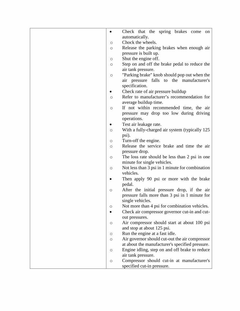
• Check that the spring brakes come on automatically.
o Chock the wheels. o Release the parking brakes when enough air
pressure is built up. o Shut the engine off. o Step on and off the brake pedal to reduce the
air tank pressure. o "Parking brake" knob should pop out when the
air pressure falls to the manufacturer's specification.
• Check rate of air pressure buildup o Refer to manufacturer’s recommendation for
average buildup time. o If not within recommended time, the air
pressure may drop too low during driving operations.
• Test air leakage rate. o With a fully-charged air system (typically 125
psi). o Turn-off the engine. o Release the service brake and time the air
pressure drop. o The loss rate should be less than 2 psi in one
minute for single vehicles. o Not less than 3 psi in 1 minute for combination
vehicles. • Then apply 90 psi or more with the brake
pedal. o After the initial pressure drop, if the air
pressure falls more than 3 psi in 1 minute for single vehicles.
o Not more than 4 psi for combination vehicles. • Check air compressor governor cut-in and cut-
out pressures. o Air compressor should start at about 100 psi
and stop at about 125 psi. o Run the engine at a fast idle. o Air governor should cut-out the air compressor
at about the manufacturer's specified pressure. o Engine idling, step on and off brake to reduce
air tank pressure. o Compressor should cut-in at manufacturer's
specified cut-in pressure.

o Test parking brake: Stop the vehicle; put the parking brake on; gently pull against it in low gear to determine if parking brake will hold.
Test service brakes. Wait for normal air pressure. • Release the parking brake. • Move the vehicle forward slowly (about 5
mph). • Apply the brakes firmly using the brake pedal. • Note any vehicle "pulling" to one side, unusual
feel, or delayed stopping action.


![RADON BIKES OVERSIZED MAGAZINE 02/2011 [english]](https://static.fdocuments.net/doc/165x107/568bbc951a28ab777e8bfbba/radon-bikes-oversized-magazine-022011-english.jpg)


![RADON BIKES OVERSIZED MAGAZINE 1/2012 [deutsch]](https://static.fdocuments.net/doc/165x107/568bf3f51a28ab89339c3b96/radon-bikes-oversized-magazine-12012-deutsch.jpg)
