OVER-THE-AIR TEST CONFIGURATIONS FOR MIMO IN LONG …
35
Bachelor's thesis Degree programme of Electronics Elecronics 2015 Tuomo Vidberg OVER-THE-AIR TEST CONFIGURATIONS FOR MIMO IN LONG TERM EVOLUTION
Transcript of OVER-THE-AIR TEST CONFIGURATIONS FOR MIMO IN LONG …

Bachelor's thesis
Degree programme of Electronics
Elecronics
2015
Tuomo Vidberg
OVER-THE-AIR TEST CONFIGURATIONS FOR MIMO IN LONG TERM EVOLUTION

BACHELOR'S THESIS | ABSTRACT
TURKU UNIVERSITY OF APPLIED SCIENCES
Electronics | Electronics
2015 | 35
Instructor Timo Tolmunen
Tuomo Vidberg
OVER-THE-AIR TEST CONFIGURATIONS FOR MIMO IN LONG TERM EVOLUTION
One of the main challenges for the mobile industry is the growing demand for the high speed mobile data. The 3GPP (3rd Generation Partner Project) is the organization that specifies most mobile data communication standards used globally. For the demand for high data rates, 3GPP has specified LTE (Long Term Evolution). One solution included in LTE among many is the MIMO (Multiple Input Multiple Output) technology.
This thesis discusses the basic features included in LTE Release 9 focusing on MIMO-technology. This thesis also discusses the MIMO-OTA (Over-the-Air) testing configurations introduced in 3GPP Technical Report 37.976. These configurations are divided into two main types: anechoic chamber-based environments and reverberation chamber-based environments. 3GPP divides these two methods into five different anechoic chamber methods and two reverberation chamber methods.
Testing MIMO-technology in LTE introduces new requirements for OTA-testing. While test requirements for GSM and WCDMA networks have included TRS (Total Radiated Sensitivity) and TRP (Total Radiated Power), the LTE MIMO testing adds the requirements for throughput testing. When using MIMO-configurations, the throughput depends on power transmitted to UE (User Equipment) that depends on the position of the UE. Addition to that, the throughput also depends on used TM (Transmission Mode). So test specifications need to include throughput tests for all TMs.
Performance of TMs and the overall performance of MIMO cannot be tested in traditional OTA-measurement chambers because the transmission channels in traditional OTA-chambers are configured to be as simple as possible, so that the power and sensitivity measurements could be repeatable. Suggestions for LTE testing chambers have included configuring the transmission channel to be more versatile. This has been achieved by methods such as using multiple antennas or including a channel emulator to the system. Using these methods, the UE’s MIMO performance can be tested in different channel environments in laboratory, therefore improving possibilities for research and development.
KEYWORDS:
LTE, Long Term Evolution, MIMO, Multiple Input Multiple Output, OTA, OTA.testing, test environments, Mobile Networks

OPINNÄYTETYÖ (AMK) | TIIVISTELMÄ
TURUN AMMATTIKORKEAKOULU
Elektroniikka | Elektroniikka
2015 | 35
Ohjaaja Timo Tolmunen
Tuomo Vidberg
MIMO:N TESTAAMINEN ILMATEITSE LONG TERM EVOLUTIONISSA
Opinnäytetyössä tutkittiin LTE-teknologian perusperiaatteita keskittyen siihen sisälletyn MIMO-tekniikan toimintaan. Opinnäytetyö tutki myös 3GPP:n TR 37.976 -raportissa esiteltyjä testausympäristövaihtoehtoja. Nämä jakautuvat 2 pääkategoriaan: kaiuttoman kammion järjestelmiin ja heijastavan kammion järjestelmiin. 3GPP jakaa nämä vielä 5:een eri kaiuttoman kammion järjestelmään ja 2:een heijastamattoman kammion järjestelmään.
MIMO-tekniikan testaaminen LTE-teknologiassa asettaa suuria vaatimuksia OTA-testaamiselle. GSM- ja WCDMA-verkkojen testaamiseen ovat riittäneet vain herkkyysmittaukset (Total Radiated Sensitivity, TRS) ja tehomittaukset (Total Radiated Power, TRP). LTE:n MIMO-tekniikka lisää testausvaatimuksiin tiedonsiirtonopeuden, joka on MIMO-tekniikkaa käytettäessä riippuvainen herkkyydestä ja lähetetystä sekä vastaanotetusta tehosta, jotka riippuvat puhelimen asennosta. Näiden lisäksi tiedonsiirtonopeus riippuu myös MIMO:n käyttämien siirtotapojen (Transmission Mode, TM) toiminnasta.
Siirtotapojen ja MIMO:n toimintaa ei pystytä testaamaan perinteisissä OTA-mittauskammioissa, sillä näissä siirtokanava on yritetty tehdä yksinkertaiseksi, jotta tehojen ja herkkyyden mittaukset olisivat mahdollisimman toistettavia. LTE:n MIMO-testauksen vaatimissa mittauskammioissa on pyritty tekemään siirtokanavasta mahdollisimman monimuotoinen. Tähän on pyritty eri ympäristövaihtoehdoissa erilaisin menetelmin, kuten käyttäen useaa antennia tai kanavaemulaattoria. Tällöin pystytään testaamaan laitteen MIMO:n toimintaa erilaisissa reaalimaailman ympäristöissä laboratorio-olosuhteissa.
ASIASANAT:
LTE, Long Term Evolution, MIMO, OTA, MIMO-OTA, Mobiiliverkot, Testaus

CONTENT
LIST OF ABBREVIATIONS 6
1 INTRODUCTION 9
2 LTE – LONG TERM EVOLUTION 11
2.1 Evolution to LTE 11
2.2 LTE Network 12
2.3 Radio Access in LTE 13
2.4 Physical Channel in LTE 14
2.5 MIMO Technology 17
2.5.1 MIMO Operation 19
2.5.2 MIMO Modes in LTE 20
3 MIMO-OTA TESTING 24
3.1 3GPP Candidate Methods for LTE MIMO-OTA Testing 24
3.1.1 Multiple Probe Method for Anechoic Chamber 25
3.1.2 Ring of Probe Method for Anechoic Chamber 25
3.1.3 Two-Stage Method for Anechoic Chamber 26
3.1.4 Two-Channel Method for Anechoic Chamber 27
3.1.5 Spatial Channel Emulator for Anechoic Chamber 28
3.1.6 Reverberation Chamber Method 28
3.1.7 Reverberation Chamber with Channel Emulator Method 30
3.2 Comparison of Methods 30
4 CONCLUSIONS 34
REFERENCES 35
FIGURES
Figure 1. Network solution from GSM to LTE. [3] 11 Figure 2. LTE network structure, S1 and X2 interfaces presented. [3] 13 Figure 3. Frequency spectrums of OFDMA and SC-FDMA. [3] 14 Figure 4. LTE downlink subframe structure, and the places of control channels in time and frequency dimensions. [4] 16
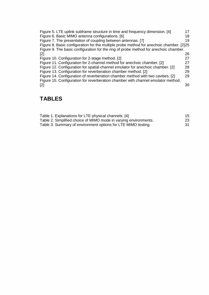
Figure 5. LTE uplink subframe structure in time and frequency dimension. [4] 17 Figure 6. Basic MIMO antenna configurations. [6] 18 Figure 7. The presentation of coupling between antennas. [7] 19 Figure 8. Basic configuration for the multiple probe method for anechoic chamber. [2] 25 Figure 9. The basic configuration for the ring of probe method for anechoic chamber. [2] 26 Figure 10. Configuration for 2-stage method. [2] 27 Figure 11. Configuration for 2-channel method for anechoic chamber. [2] 27 Figure 12. Configuration for spatial channel emulator for anechoic chamber. [2] 28 Figure 13. Configuration for reverberation chamber method. [2] 29 Figure 14. Configuration of reverberation chamber method with two cavities. [2] 29 Figure 15. Configuration for reverberation chamber with channel emulator method. [2] 30
TABLES
Table 1. Explanations for LTE physical channels. [4] 15 Table 2. Simplified choice of MIMO mode in varying environments. 23 Table 3. Summary of environment options for LTE MIMO testing. 31
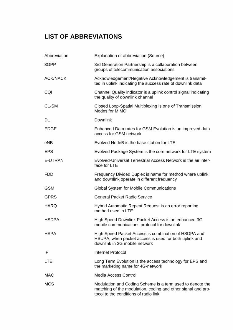
LIST OF ABBREVIATIONS
Abbreviation Explanation of abbreviation (Source)
3GPP 3rd Generation Partnership is a collaboration between groups of telecommunication associations
ACK/NACK Acknowledgement/Negative Acknowledgement is transmit-ted in uplink indicating the success rate of downlink data
CQI Channel Quality indicator is a uplink control signal indicating the quality of downlink channel
CL-SM Closed Loop-Spatial Multiplexing is one of Transmission Modes for MIMO
DL Downlink
EDGE Enhanced Data rates for GSM Evolution is an improved data access for GSM network
eNB Evolved NodeB is the base station for LTE
EPS Evolved Package System is the core network for LTE system
E-UTRAN Evolved-Universal Terrestrial Access Network is the air inter-face for LTE
FDD Frequency Divided Duplex is name for method where uplink and downlink operate in different frequency
GSM Global System for Mobile Communications
GPRS General Packet Radio Service
HARQ Hybrid Automatic Repeat Request is an error reporting method used in LTE
HSDPA High Speed Downlink Packet Access is an enhanced 3G mobile communications protocol for downlink
HSPA High Speed Packet Access is combination of HSDPA and HSUPA, when packet access is used for both uplink and downlink in 3G mobile network
IP Internet Protocol
LTE Long Term Evolution is the access technology for EPS and the marketing name for 4G-network
MAC Media Access Control
MCS Modulation and Coding Scheme is a term used to denote the matching of the modulation, coding and other signal and pro-tocol to the conditions of radio link

MIMO Multiple Input Multiple Output is the name for multiple an-tenna technique used in LTE, where there are multiple trans-mitting antennas and multiple receiving antennas.
MISO Multiple Input Single Output is a multiple antenna technique used in LTE, where there are multiple transmitting antennas, but just one receiving antenna
MU-MIMO Multi User-MIMO is a multiple antenna technique where mul-tiple transmitting antennas transmit the signal to multiple user equipment
OFDMA Orthogonal Frequency Divided Multiple Access is the multi-carrier technology used in LTE downlink signaling
OL-SM Open Loop-Spatial Multiplexing is one of Transmission Modes for MIMO
OTA Over the Air
PAPR Peak-to-Average-Power Ratio
PCFICH Physical Control Format Indicator Channel is name for down-link physical control channel
PDCCH Physical DL Control Channel is a downlink physical control channel
PHICH Physical Hybrid Automatic Repeat Request Indicator Chan-nel is a downlink physical control channel
PMI Pre-coding Matrix Indicator is a feedback provided from UE to eNB while using TM 4
RB Resource Block consists of 12 sub-carriers for the duration of one slot
RE Resource Element is the smallest defined unit which consists of one OFDM sub-carrier during one OFDM symbol interval
SC-FDMA Single Carrier – Frequency Divided Multiple Access is a technology used in LTE uplink
SCME Spatial Channel Model Extended is an extended model for 3GPP’s Spatial Channel Model. SCME includes some more features
SIMO Single Input Multiple Output is multiple antenna method, where is one transmitting antenna and multiple receiving an-tenna
SINR Signal-to-Interference-plus-Noise Ratio
SISO Single Input Single Output is the traditional single antenna method

SU-MIMO Single User-MIMO is the basic MIMO configuration, where there are multiple streams transmitted to one user
TB Transport Block is synonym to slot and consists of 2 slots
TDD Time Divided Duplex is the technique where uplink and downlink operate in same frequency, but not simultaneously
TDMA Time Division Multiple Access is a channel access method that allows several users to use same frequency for trans-mission
TD-SCDMA Time Division Synchronous Code Division Multiple Access is time divided access method for 3G networks
TM Transmission Mode is name for MIMO-modes used in LTE
TRI Transmit Rank Indicator is indicator transmitted from UE to eNB to determine the used modulation and transmission mode
TRP Total Radiated Power
TRS Total Radiated Sensitivity
UE User Equipment
UL Uplink
UMTS Universal Mobile Terrestrial System is a 3rd generation mo-bile cellular system for networks
WCDMA Wideband Code Division Multiple Access is the access method of 3rd mobile generation

9
TURKU UNIVERSITY OF APPLIED SCIENCES THESIS | Tuomo Vidberg
1 INTRODUCTION
The requirement for high data rates for wireless transmission at the moment is
exponentially growing and the mobile industry is trying to keep up with the mar-
ket’s needs. 3GPP (3rd Generation Partnership Project) is the specification or-
ganization that is constantly working on new ways to improve mobile data rates.
In 2008 3GPP released a technology called LTE (Long Term Evolution) to im-
prove the data rates.
The 3GPP’s Release 9 introduced the Multiple Input Multiple Output (MIMO) tech-
nology, which is one main technology used to improve overall data rates in the
mobile network. MIMO has been a cornerstone of the LTE standard, but initially,
in Releases 8 and 9 multiple transmit antennas on the UE (User Equipment) was
not supported because in interest of the power reduction, only a single RF power
amplifier was assumed to be available. In Release 10 3GPP introduced support
for multiple antennas on the UE and also a number of new schemes to LTE in-
cluding CL-SM (Closed Loop Spatial Multiplexing) for SU-MIMO (Single User-
MIMO). [1]
Basically the only way of testing performance of MIMO technology is performing
the tests OTA. The testing for OTA has been specified for GSM and WCDMA
(Wideband Code Divided Multiple Access) by 3GPP, but specifications for LTE
OTA are still ongoing. Conducted testing method has some limitations, such as
testing the antenna performance, which can be gone around testing user equip-
ment Over the Air. 3GPP also implies that MIMO performance testing could also
imitate field testing conditions better, when performing testing OTA.
There are seven testing environment configurations that 3GPP has suggested for
implementation of MIMO-OTA testing in TR 37.976 [2]. There are two primary
topologies, anechoic chamber based methods and reverberation chamber based
methods. Anechoic chamber method is divided into five different configurations
and reverberation chamber method is divided to two different configurations.

10
TURKU UNIVERSITY OF APPLIED SCIENCES THESIS | Tuomo Vidberg
Globally there are few theses made on MIMO-OTA testing for LTE, but none of
these have compared the methods 3GPP have suggested for testing. This is
probably because the investments for company to study different environments
in practice, would be radical.
This thesis briefly covers the basics of LTE technology and concentrates on
MIMO technology and transmission modes used in LTE and discusses about the
MIMO-OTA testing candidates that 3GPP has offered. Finally thesis compares
the upsides and downsides of the test candidates.

11
TURKU UNIVERSITY OF APPLIED SCIENCES THESIS | Tuomo Vidberg
2 LTE – LONG TERM EVOLUTION
This chapter gives an overview of the LTE technology. The chapter also goes
through the evolution from GSM systems to LTE, so it would be easier to under-
stand why and how LTE is that much different compared to other mobile base-
band systems. This chapter gives sight of the LTE architecture and basic tech-
nologies used, such as radio access methods. MIMO technology is in key role in
this chapter, since it has great impact on OTA testing and performance.
2.1 Evolution to LTE
LTE or the E-UTRAN (Evolved Universal Terrestrial Access Network), introduced
in 3GPP Release 8, is the access technology of the EPS (Evolved Packet Sys-
tem). In specification the main requirements for LTE network were high peak data
rates, short round trip time, high spectral efficiency as well as flexibility in fre-
quency and bandwidth. [3]
Figure 1. Network solution from GSM to LTE. [3]
Figure 1 shows the main differences in evolution of network solutions from GSM
to LTE. GSM was originally developed to carry real time services in a circuit
switched manner, with data services only possible over a circuit switched modem
connection, which resulted in very low data rates. In evolution from GSM to GPRS

12
TURKU UNIVERSITY OF APPLIED SCIENCES THESIS | Tuomo Vidberg
the first step towards an IP based packet switched solution was taken, while con-
tinuing the usage of the same air interface and access method, TDMA (Time Di-
vision Multiple Access). [3]
In pursuit to reach higher data rates for the next generation a new access tech-
nology WCDMA (Wideband Code Division Multiple Access) was developed for
UMTS (Universal Mobile Terrestrial System). For real time services the access
network in UMTS emulates a circuit switched connection and for data services a
packet switched connection. In UMTS the IP (Internet Protocol) address is allo-
cated to the UE when a data service is established and released when the ser-
vices is released. [3]
The EPS and therefore the LTE is purely IP based. Real time services and data
services are carried by the packet switched connection. The IP address is allo-
cated to UE when terminal is switched on and released when UE switched off.
For LTE the theoretical data rates are 300 Mbps for downlink and 75 Mbps for
uplink. There are multiple methods used to achieve these data rates: the new
access methods for downlink and uplink, modulations used for transmit channels,
bandwidths up to 20 MHz and multiple MIMO configurations. [3]
Downlink in LTE network uses OFDMA (Orthogonal Frequency Division Multiple
Access) and uplink uses SC-FDMA (Single Carrier-Frequency Division Multiple
Access). The used modulations are QPSK, 16QAM and 64QAM and used band-
widths are 1.4MHz, 3 MHz, 5 MHz, 10 MHz and 20 MHz. [3]
2.2 LTE Network
The LTE access network is a network of base stations, evolved NodeBs (eNB).
This generates a flat architecture which is demonstrated in Figure 2. There is no
centralized intelligent controller, and the eNBs are inter-connected via the X2-
interface and towards the core network by the S1 interface. The distribution of
intelligence between eNBs improves the connection set-up speed and reduces
the handover time between base stations. [3]

13
TURKU UNIVERSITY OF APPLIED SCIENCES THESIS | Tuomo Vidberg
Figure 2. LTE network structure, S1 and X2 interfaces presented. [3]
Another advantage with the distributed intelligence solution gives, is that the MAC
(Media Access Control) protocol layer, which is responsible for scheduling, can
be only performed in the UE. [3]
2.3 Radio Access in LTE
To achieving the enable scheduling in both time and frequency domain and to
achieve high spectral efficiency, a multicarrier approach was chosen for LTE. The
downlink is handled with OFDMA (Orthogonal Frequency Division Multiple Ac-
cess) and the uplink is handled with SC-FDMA (Single Carrier-Frequency Multi-
ple Access). [3]

14
TURKU UNIVERSITY OF APPLIED SCIENCES THESIS | Tuomo Vidberg
Figure 3. Frequency spectrums of OFDMA and SC-FDMA. [3]
OFDMA is a multicarrier technology where available bandwith is divided into mul-
tiple mutual orthogonal narrowband subcarriers. In OFDMA these subcarriers al-
located between multiple users. The OFDMA leads to high PAPR (Peak-to-Aver-
age Power Ratio) which requires expensive power amplifiers with high require-
ments on linearity, this increases power consumption for the transmitter. For eNB
this does not show as a problem, but for UEs this would lead to expensive solu-
tions. [3]
As seen in Figure 3, the SC-FDMA spectrum consists of signal with single carrier
characteristics, and therefore low PAPR. Flexible frequency allocation and good
multipath resistance were also reason for selecting SC-FDMA for uplink signal-
ing. [3]
2.4 Physical Channel in LTE
LTE defines a number of channels for the both DL (Downlink) and UL (Uplink).
Table 1 defines DL and UL physical channels. The structure for DL (Downlink)
subframe is common for both FDD (Frequency Divided Duplex) and TDD (Time
Divided Duplex). [4]

15
TURKU UNIVERSITY OF APPLIED SCIENCES THESIS | Tuomo Vidberg
This structure is shown in Figure 4 for four transmitting antennas. Each subframe
consists of two slots of length 0.5 ms. Slots consists of seven OFDM symbols.
The reference symbols are located in each slot. For DL the control channels are
located in the first three OFDM symbols, followed by the data transmission.. Each
element in the time and frequency resource grid is called a RE (Resource Ele-
ment). Each DL subframe contains control information, data transmission and
reference signals. PCFICH (Physical Control Format Indicator Channel), PHICH
(Physical Hybrid Automatic Repeat Request (HARQ) Indicator Channel) and
PDCCH (Physical DL Control Channel) provide the control signaling for DL. [5]
The scheduling assignment for DL and UL are transmitted on the PDCCH, which
is addressed to a specific user. PDCCH also contains control information needed
for data reception and demodulation. The data allocation is assigned for users in
quantity of RBs (Resource Block). [4]
Table 1. Explanations for LTE physical channels. [4]

16
TURKU UNIVERSITY OF APPLIED SCIENCES THESIS | Tuomo Vidberg
The UL subframe structure is also common for both FDD and TDD. Similar to DL
subframe, UL subframe also consists two slots that are 0.5 ms long, with one
reference symbol located in each slot. UL control signaling such as CQI (Channel
Quality Indicator) and ACK/NACK (Acknowledgment/Negative Acknowledgment)
are located in the edge of UL band. Since the UL only supports one antenna in
Release 8 and Release 9, there are no reference signals for multiple antennas.
The uplink subframe structure is shown in Figure 5. [4]
Figure 4. LTE downlink subframe structure, and the places of control channels in time and frequency dimen-sions. [4]

17
TURKU UNIVERSITY OF APPLIED SCIENCES THESIS | Tuomo Vidberg
2.5 MIMO Technology
3GPP introduces in Rel. 9 a multiple antenna technique called MIMO (Multiple
input Multiple output) to LTE. MIMO technology was introduced to increase ro-
bustness coverage or capacity and data rate of physical layer by adding more
antennas to radio system. There are four different basic MIMO configurations that
can be used, shown in Figure 4. These are SISO (Single Input Single Output),
MISO (Multiple Input Single Output), SIMO (Single Input Multiple Output) and
MIMO (Multiple Input Multiple Output).
Figure 5. LTE uplink subframe structure in time and fre-quency dimension. [4]

18
TURKU UNIVERSITY OF APPLIED SCIENCES THESIS | Tuomo Vidberg
Figure 6. Basic MIMO antenna configurations. [6]
MIMO can be used for two main purposes: Increasing the coverage and robust-
ness of data transmission or increasing the data rate and capacity.
Increasing the robustness of data transmission can be done using a diversity an-
tenna or multiple diversity antennas. These antennas transmit the same data
stream as primary TX antenna increasing the SNR (Signal-to-Noise Ratio).
Increase in the data rate can be achieved using spatial multiplexing techniques.
Data is divided into multiple separate streams, which are transmitted simultane-
ously over the same air interface. The transmission is included with special sec-
tions, also known as reference signals that are known in the receiver. The re-
ceiver can perform a channel estimation for each transmitted signal streams.
While using spatial multiplexing, the space dimension is therefore used more than
once, making data transfer more spectral efficient. [7]
The number of spatial layters of the radio channel is a key factor to MIMO’s spatial
multiplexing technique performance. The number of spatial layers determines the

19
TURKU UNIVERSITY OF APPLIED SCIENCES THESIS | Tuomo Vidberg
spectral efficiency. Spatial layers are born from scattering environment and mul-
tipath of the channel between the transmitter and the receiver. Another key com-
ponent to performance is the number of transmitting and receiving antennas. The
rank is a measure of the number of independent spatial layers. Hence, a 4×2
MIMO system provides double the data rate, provided that there are two spatial
layers in the wireless channel. If it is a line-of-sight condition, the channel matrix
is 1, so even with four antennas the spectral efficiency of the channel cannot be
increased in line-of-sight case. Also the correlation between the data streams will
be too high. So there is only one spatial stream in line-of-sight situation. [7]
2.5.1 MIMO Operation
MIMO operation can be understood by using a static equivalent circuit to repre-
sent the channel. The channel for MIMO m × n system is represented as ports
which demonstrate the channels amplitude and phase responses. In the Figure
7 these are marked as h00, h01, h10 and h11 to hnm.
Figure 7. The presentation of coupling between antennas. [7]

20
TURKU UNIVERSITY OF APPLIED SCIENCES THESIS | Tuomo Vidberg
As it can be seen from figure there will never be ideal case, since in ideal case
signal from TX0 would go only to RX0 and signal from TX1 only to RX1. In prac-
tice, this is impossible to achieve and there will always be coupling between sig-
nals as soon as they are transmitted. Therefore the challenge is to reverse the
coupling after the signals have been received. For this purpose LTE uses a “non-
blind” technique. That means that pre-defined orthogonal training signals are
transmitted from all transmitting antennas. The receiver knows which training sig-
nals were used for each antenna and therefore the channel amplitude and phase
responses can be calculated.
2.5.2 MIMO Modes in LTE
In release 9 LTE can use seven modes of MIMO for downlink paths [7]. These
are called TMs (Transmission Mode):
TM 1 – Single-antenna port; port 0: This is analogous to most current cellular
systems such as GSM, GPRS and EDGE, where a single data stream is trans-
mitted on one antenna and received by either one (SISO) or more antennas
(SIMO).
TM 2 – Transmit diversity: This is the default mode in LTE. Transmit diversity
mode involves the transmission of the same data stream on multiple antennas (in
Release 11, LTE supports usage of up to eight antennas). [7]
This mode is used in LTE by default for the Common Channels as well as for
control and broadcast channels. Since it is a single-layer it is used to make signal
quality more robust and by using transmit diversity also lower SINR (Signal to
Interference plus Noise Ratio) is required to decode signal rather than improving
the peak data rate. [7]
In LTE, transmit diversity is used as a fallback option for some transmission
modes, such as when spatial multiplexing cannot be used. Control channels are
also transmitted using transmit diversity. [7]

21
TURKU UNIVERSITY OF APPLIED SCIENCES THESIS | Tuomo Vidberg
TM 3 – Open loop-spatial multiplexing (OL-SM): In case of OL-SM, two data
streams are transmitted over two or more antennas (up to 4 in LTE and up to 8
in LTE-A (LTE-Advanced)). There is no explicit feedback from the UE, although
a TRI (Transmit Rank Indication) transmitted by the UE is used by the base sta-
tion to select the number of spatial layers. [7]
As multiple data streams are transmitted, OL-SM provides better peak throughput
than transmit diversity that transmits only one stream at a time. It is also relatively
simple to implement and is one of the main modes of MIMO implemented in LTE
systems. [7]
TM 4 – Closed loop spatial multiplexing (CL-SM): This mode is similar to the OL-
SM, two data streams are transmitted from up to 4 antennas. The difference is
PMI (Pre-coding Matrix Indicator) which is fed back from the UE to the base sta-
tion. This feedback mechanism allows the transmitter to pre-code the data to op-
timize transmission over the wireless channel so the signals at the receiver can
be easily separated into the original streams. This mode is expected to be highest
performing mode of MIMO in LTE. [7]
TM 5 – Multi-User MIMO (MU-MIMO): In MU-MIMO, separate data streams are
sent to spatially separated UEs over the same sub-channel, with each UE serving
as one of the multiple receiving antennas. This way the overall capacity of system
can be increased, though it does not increase the throughput of individual UE
over single antenna technique. Same way as single user techniques, the MU-
MIMO is dependent on rich scattering environment for low correlation on each
UE to decode the data streams meant for that UE. In case of spatial layers are
not completely orthogonal, individual users will experience interference from
other users. [7]
In LTE Release 9 MU-MIMO is expected to have lower performance than SU-
MIMO. [7]. As a result, MU-MIMO is not expected to be widely deployed until LTE
networks are starting to become heavily loaded.

22
TURKU UNIVERSITY OF APPLIED SCIENCES THESIS | Tuomo Vidberg
TM 6 – Closed loop Rank 1 with pre-coding: This mode represents the scenario
when a single data stream is transmitted over a single spatial layer. Many con-
sider this case to be a fall back scenario of CL-SM and it has been associated
with beam-forming. [7]
TM 7 – Single-antenna port; Port 5: This is a beam-forming mode where a single
data stream is transmitted over a single spatial layer. A dedicated reference sig-
nal forms an additional antenna port and allows transmission from more than 4
antennas. The terminal estimates the channel quality from the common reference
signal on antennas 1-4. Linear antenna arrays are expected to be used for this
mode. [7]
MIMO performance depends on a number of factors such as the signal quality
which is measured by SINR (Signal-to-Interference-Plus-Noise Ratio), the state
of the channel (for example low vs. high scattering environment), the speed of
the mobile terminal and the correlation of the received signals at the receiver
antennas. For that reason in varying environments certain MIMO modes are more
efficient that other. [8]
The benefits of open and closed loop spatial multiplexing schemes are achieved
when the SINR is at its highest. At the cell edge, a weak signal strength and high
SNR (Signal-to-Noise Ratio) reduce the benefits of spatial multiplexing modes. In
those scenarios Closed-loop Rank 1 or Transmit Diversity become more efficient.
Transmit Diversity is also more attractive than CL-SM and OL-SM in environment
where signal scattering is low, which could be for example rural areas. Switching
between these modes as the mobile terminal moves away from cell center or the
scattering environment changes is crucial for optimizing the system performance.
[8]
As mentioned, the speed of mobile terminal impacts the performance of MIMO
systems. In general in high speeds the CL-SM mode provides better spectral ef-
ficiency than OL-SM mode as the channel parameters are fed back to the trans-
mitter from the receiver and used to code the data stream. However, as the speed
of the mobile terminal increases and channel conditions change more rapidly,

23
TURKU UNIVERSITY OF APPLIED SCIENCES THESIS | Tuomo Vidberg
CL-SM loses much of its advantage over OL-SM since delays and inaccuracies
are affecting the channel feedback to the transmitter, therefore the transmitter
cannot adjust the channel optimally. The OL-SM is also simpler to implement
compared to the CL-SM, which makes it more attractive solution for developers
of LTE terminals. Transmit diversity is robust to speed while its performance in
low scattering environment and high SINR does not degrade as that of OL-SM.
Therefore, for a vehicle moving with high speed along a highway with a clear line
of sight to the base station, transmit diversity would provide the better spectral
efficiency while OL-SM would be preferred when the terminal is moving at high
speed in a rich multipath environment and high SINR. [8]
Spatial multiplexing schemes perform best when the signals have low correlation
coefficient. As the signal correlation increases the performance of SM schemes
decrease. Signal correlation is related to the scattering environment of the chan-
nel between base station and UE. So the higher signal scattering the more effec-
tive spatial multiplexing becomes. In urban areas, which are high-scattering en-
vironment, the received signal has a relatively large angular spreads, the spatial
multiplexing schemes are expected to perform at their best. [8]
Signal correlation is also dependent on the placement of the antennas. The larger
distance between the multiple antennas at each of the transmitter and receiver,
the lower correlation and better performance of SM schemes can be achieved.
This is a challenge for antenna design composing up to four downlink antennas
as far away from each other into small mobile terminal.
Table 2. Simplified choice of MIMO mode in varying environments.

24
TURKU UNIVERSITY OF APPLIED SCIENCES THESIS | Tuomo Vidberg
3 MIMO-OTA TESTING
The primary Figure of Merit (FOM) in MIMO-OTA testing for LTE, is throughput.
MIMO-OTA throughput is defined as the time-average of correctly received
transport blocks. The MIMO-OTA throughput is measured, in the same point as
in conductive measurement setup, at top of the physical layer of LTE. The eNB
simulator sends fixed sized payload bits to the UE, the UE sends back either ACK
or NACK to the eNB simulator. The formula to count the MIMO throughput:
MIMO-OTA tests are performed in chamber-based environments, in which wire-
less channel emulators apply real-world spatial channel modes to the signals sent
to antenna probes mounted in the chamber. This allows for vendor or customer
to precisely characterize how well UE with MIMO can receive signals with these
real-world spatial properties. [10]
3.1 3GPP Candidate Methods for LTE MIMO-OTA Testing
As a result of the 3GPP study, seven different test methods have been proposed
to 3GPP in TR 37.967 [2] for creating the necessary environment to test MIMO
performance. Test methods can be separated into two main groups: anechoic
chambers methods and reverberation chamber methods. There are five method
candidates which use anechoic chamber and two that use reverberation cham-
ber. [2]
The anechoic and reverberation methods take fundamentally different ap-
proaches towards achieving the same goal – the creation of a spatially diverse
radio channel. In anechoic chamber, multiple probes are used to launch signals
at the UE in order to create known angles of arrival, which map onto the required
channel spatial model. This approach is powerful, although in order to achieve
arbitrary channel model flexibility, large number of antenna probes are required,

25
TURKU UNIVERSITY OF APPLIED SCIENCES THESIS | Tuomo Vidberg
which increases the price and makes calibrating more challenging due to issues
like back scattering. In case of reverberation chamber method, the spatial rich-
ness is provided by relying on the natural reflections within the chamber. These
reflections can be further randomized by use of mode stirrers that oscillate to
provide spatial field, which over long periods of time approach an isotropic field.
The following previews of methods are collected from TR 37.967 [2].
3.1.1 Multiple Probe Method for Anechoic Chamber
The configuration for this method is shown in Figure 8. This method is conceptu-
ally the most simple since there is a direct relationship between the required an-
gular spread of the channel and the physical location of the probes. The goal is
to create the desired channel model by positioning an arbitrary number of probe
antennas in arbitrary positions in the anechoic chamber equidistant from UE. All
probe antennas are faded by a channel emulator to provide the desired temporal
component. So the tuning the environment for specific requirement is done by
moving the antenna probes around the chamber. [2]
Figure 8. Basic configuration for the multiple probe method for anechoic chamber. [2]
3.1.2 Ring of Probe Method for Anechoic Chamber
The ring of probes method is based on symmetric ring of probe antennas equi-
distant around the UE, which is placed at the center of the anechoic chamber as

26
TURKU UNIVERSITY OF APPLIED SCIENCES THESIS | Tuomo Vidberg
shown in Figure 9. Similar to the multiple probe method, each probe is controlled
by a channel emulator to generate characteristics of the desired channel model.
In the ring of probes method there is no longer fixed relationship between the
probe antennas and the angle of departure. Instead, the spatial components of
the channel model are mapped into the probe antennas in such way that the
angular spreads can be generated. This solution provides any 2D spatial channel
model without having to reposition the probe antennas. [2]
Figure 9. The basic configuration for the ring of probe method for anechoic cham-ber. [2]
In ring of probes method the number of the probes effect the accuracy with which
the spatial dimension of the channel mode can be simulated. [2]
3.1.3 Two-Stage Method for Anechoic Chamber
The two-stage method takes a different approach to creating the necessary con-
ditions to test MIMO performance. The configuration is shown in Figure 10. The
first stage involves the measurement of the 3D antenna pattern of the UE using
an anechoic chamber. The second stage takes measured antenna pattern and
convolves it with the desired channel model using a channel emulator. The output
of the channel emulator represents the faded downlink signal modified by the
spatial properties of the UEs antenna. The signal then is conducted to the UE

27
TURKU UNIVERSITY OF APPLIED SCIENCES THESIS | Tuomo Vidberg
with RF cables. Therefore the second stage does not require chamber environ-
ment. [2]
Figure 10. Configuration for 2-stage method. [2]
3.1.4 Two-Channel Method for Anechoic Chamber
The Two-Channel method is a special case of the multiple probe method with just
two probes and no channel emulator. The principle of this method is to evaluate
the impact of the direction and angular separation of the two signals on the UE’s
performance. Two-channel method is shown in Figure 9. [2]
Figure 11. Configuration for 2-channel method for anechoic chamber. [2]

28
TURKU UNIVERSITY OF APPLIED SCIENCES THESIS | Tuomo Vidberg
3.1.5 Spatial Channel Emulator for Anechoic Chamber
The Spatial Channel Emulator is a variation of the Ring of Probes method, where
the channel emulatior is replaced with much simpler programmable attenuator
and phase shifter per antenna. The setup is shown in Figure 12. [2]
Figure 12. Configuration for spatial channel emulator for anechoic chamber. [2]
By controlling the amplitude and phase in real time, a Rayleigh distribution or
other relevant multipath distribution can be obtained. [2]
3.1.6 Reverberation Chamber Method
The reverberation chamber method uses the reflective properties of the reverber-
ation chamber with mode-stirrers to transform the downlink test signal into a 3D
multipath signal. The spatial characteristics of the signal are random and can be
shown to be isotropic over time. But they can also be observed to be highly di-
rectional, when observed over time period of demodulated data symbol. This un-
uniformity provides the UE diverse signals on each antenna enabling multiplexing
gain. Example of implementation is shown in Figure 13. [2]

29
TURKU UNIVERSITY OF APPLIED SCIENCES THESIS | Tuomo Vidberg
Figure 13. Configuration for reverberation chamber method. [2]
This reverberation chamber method including only reverberation chamber with
mode-stirrers is limited relatively slow Doppler spectrum that is determined by the
speed of mode-stirrer and only single fixed power delay profile. One option for
further control of the power delay profile and spatial aspects can be obtained by
cascading two or more reverberation chambers together as shown in Figure 14.
[2]
Figure 14. Configuration of reverberation chamber method with two cavities. [2]

30
TURKU UNIVERSITY OF APPLIED SCIENCES THESIS | Tuomo Vidberg
3.1.7 Reverberation Chamber with Channel Emulator Method
The second reverberation method is reverberation method with channel emula-
tor. The channel emulator can be used to pass limitations of the reverberation
method on Doppler spectrum and power delay profile by adding fading scenarios
to the downlink signal before signal is launched into the chamber. This makes the
channel mode fully controllable, although the natural and very short decay time
of the chamber will spread the power delay profile. The basic principle can be
seen in Figure 15. [2]
Figure 15. Configuration for reverberation chamber with channel emulator method. [2]
Power delay profiles of 3GPP SCME (Spatial Channel Model Extended) channel
modes can be emulated with reverberation chamber with channel emulator
method, when the used channel emulator is capable of negative time delays and
in the chamber there are multiple cavity stirrers. [2]
3.2 Comparison of Methods
As discussed in previous chapter, there are multiple options suggested by 3GPP
to implement a LTE MIMO-OTA test environment. Summary of these methods
collected from TR 37.967 [2] are listed in Table 3.

31
TURKU UNIVERSITY OF APPLIED SCIENCES THESIS | Tuomo Vidberg
Table 3. Summary of environment options for LTE MIMO testing.
An
ech
oic
ch
am
be
r
Spatia
l
channe
l
em
ula
tor
1
Contr
olla
ble
Contr
olla
ble
Contr
olla
ble
Contr
olla
ble
SC
ME
, sin
gle
-
clu
ste
r,
Uni-
form
arb
itra
ry
2-s
tage
1
Contr
olla
ble
Contr
olla
ble
Contr
olla
ble
Contr
olla
ble
SC
ME
, sin
gle
-
clu
ste
r,
Uniform
arb
itra
ry
2-c
hann
el
2-3
Contr
olla
ble
Contr
olla
ble
Contr
olla
ble
Contr
olla
ble
SC
ME
, sin
gle
-
clu
ste
r,
Uni-
form
arb
itra
ry
Rin
g o
f pro
bes
8-3
2
Contr
olla
ble
Contr
olla
ble
Contr
olla
ble
Contr
olla
ble
SC
ME
, sin
gle
-
clu
ste
r,
Uni-
form
arb
itra
ry
Sin
gle
Clu
ste
r
3-1
6
Contr
olla
ble
Contr
olla
ble
Contr
olla
ble
Contr
olla
ble
Sin
gle
-
clu
ste
r,
multip
ath
(varies)
Reve
rbera
tio
n c
ham
ber
Reverb
era
tion
cham
ber+
Ch
ann
e
l em
ula
tor
2-9
Rand
om
Contr
olla
ble
+
Expon
entia
l
Contr
olla
ble
Contr
olla
ble
Uniform
spatia
l,
contr
olla
ble
multip
ath
Reverb
er
atio
n
cham
ber
2-9
Rand
om
Expon
en
tia
l
decay
Slig
htly
contr
olla
ble
decay
Lim
ite
d
Unifro
m
Att
rib
ult
e
Nu
mb
er
of
pro
be
an
ten
nas
An
gu
lar
Sp
read
Po
wer
dela
y
pro
file
Dela
y s
pre
ad
Do
pp
ler
sh
ift
Su
pp
ort
ed
ch
an
nel
mo
des

32
TURKU UNIVERSITY OF APPLIED SCIENCES THESIS | Tuomo Vidberg
For LTE MIMO testing OTA, there are some requirements for including multiple
spatial streams, making it necessary to either have multiple input antenna probes
in testing system, include channel emulator or use both of these options. While
comparing these methods, the first choice to be made is between anechoic and
reverberation chambers.
Anechoic chamber offers five choices to choose from, while reverberation cham-
ber offers two methods. First notion to be made from Table 3 is that the require-
ment for channel emulator is quite obvious and the only method that does not
include channel emulator is the reverberation channel method. The investment
for channel emulator is relatively cheap and the benefits for including one to the
test environment are obvious.
The reverberation chamber with channel emulator offers a simple way to achieve
isotropic field around the UE for relatively low cost, but lacs possibility to control
Angular spread. Other possibilities are almost identical for anechoic chamber
methods and reverberation chamber with channel emulator, only difference being
in few supported channel modes.
Therefore the decision between the anechoic chamber and reverberation cham-
ber is complicated. Since the methods including anechoic chamber require more
antenna probes than environments using reverberation chamber, they are likely
to be more expensive and assumedly more complicated to implement. But the
environments using anechoic chamber offer possibility to control the angular
spread, which is not controllable in reverberation chamber, even with channel
emulator included in test environment. Therefore the decision is always individual
for every manufacturer’s needs, if the controllability for angular spread is critical,
the investment for anechoic chamber, channel emulator and required antenna
probes is completely reasonable.
If manufacturer uses reverberation chamber to implement LTE MIMO-OTA test
environment, the obvious choice is to use channel emulator. With this option the
investment is not that great, but the benefits are massive. If manufacturer decides
to implement test environment using one of the anechoic chamber methods, the

33
TURKU UNIVERSITY OF APPLIED SCIENCES THESIS | Tuomo Vidberg
choice is not that simple. Since all methods with anechoic chamber offer basically
the same functionalities, this decision is dependent on individual manufacturer’s
needs and requirements.

34
TURKU UNIVERSITY OF APPLIED SCIENCES THESIS | Tuomo Vidberg
4 CONCLUSIONS
In 2015 there are still no full specifications for LTE MIMO-OTA. The 3GPP
TS34.114 [11] states that for specified systems: GSM, WCDMA and TD-SCDMA,
the only required measurements for OTA-testing are TRP (Total Radiated Power)
and TRS (Total Radiated Sensitivity). The LTE specifications will most likely also
include these tests, but combined with testing requirements for MIMO antenna
configurations and performance requirements for transmission modes with
throughput being the primary focus of testing.
3GPP suggests seven different testing methods for LTE MIMO-OTA testing.
These include five anechoic chamber methods and two reverberation chamber
methods. Between the two reverberation chamber methods, the difference is the
added channel emulator in another one. With anechoic chamber methods there
are few different approaches to solve the problem. There is a straight forward
method of applying multiple antenna probes to system, creating a field around
the UE. The other way is the two-staged method, where antenna array is meas-
ured in first stage, and then applied to the throughput measurements are done
with conducted testing method.
For LTE MIMO testing OTA, there are requirements for including multiple spatial
streams, making it necessary to either multiply input antennas in testing system,
include channel emulator or use both options. The decision between the anechoic
chamber and reverberation chamber is more complicated. And therefore the de-
cision is individual for all manufacturers’ depending on the specific needs and
requirements.
If manufacturer uses reverberation chamber to implement LTE MIMO-OTA test
environment, the obvious choice is to use channel emulator. But in case of man-
ufacturer decides to implement one of the methods using anechoic chamber, the
choice is equally difficult. Since all methods offer basically the same applications,
therefore this decision is dependent on individual manufacturer’s needs and re-
quirements.

35
TURKU UNIVERSITY OF APPLIED SCIENCES THESIS | Tuomo Vidberg
REFERENCES
[1] Ian Poole, LTE MIMO: Multiple Input Multiple Output Tutorial. [Online Document]. http://www.radio-electronics.com/info/cellulartelecomms/lte-long-term-evolution/lte-mimo.php (Accessed 18.12.2014)
[2] 3GPP Technical Report, ETSI TR 137 976 V11.0.0 (2012-11) Universal Mobile Telecom-munications System (UMTS); LTE; Measurement of radiated performance for Multiple In-put Multiple Output (MIMO) and multi-antenna reception for High Speed Packet Access (HSPA) and LTE terminals (3GPP TR 37.976 version 11.0.0 Release 11). [Online docu-ment]. http://www.etsi.org/de-liver/etsi_tr/137900_137999/137976/11.00.00_60/tr_137976v110000p.pdf (Accessed 27.1.2015)
[3] Magdalena Nohrborg, LTE Overview. [Online document]. http://www.3gpp.org/technolo-gies/keywords-acronyms/98-lte (Accessed 2.2.2015)
[4] Amitava Ghosh, Repeepat Ratasuk, Bishwarup Mondal, Nitin Mangalvedhe and Tim Thomas, Motorola INC. LTE-Advanced: Next-Generation Wireless Broadband Technology. [Online Document]. http://www.dcc.fc.up.pt/~slc/aulas/RCM/1415/Trabalho/pa-pers/05490974.pdf
[5] Artiza Networks, Physical Channel Structure. [Online Document]. http://www.artizanet-works.com/lte_tut_phy_cha.html
[6] Evercom Communications, Understanding of SISO, SIMO, MISO and MIMO. [Online Doc-ument] http://www.evercom.com.tw/msg/msg8.html (Accessed 1.2.2015)
[7] Rohde Schwartz, LTE Transmission Modes and Beamforming, White Paper. [Online Docu-ment]. http://cdn.rohde-schwarz.com/pws/dl_downloads/dl_application/applica-tion_notes/1ma186/1MA186_1e_LTE_TMs_and_beamforming.pdf (Accessed 15.2.2015)
[8] LTE World, Seven Modes of MIMO in LTE, White Paper. [Online Document]. http://lte-world.org/whitepaper/seven-modes-mimo-lte (Accessed 15.2.2015)
[9] 3G Americas, 3GPP Mobile Broadband Innovation Path to 4G: Release 9, Release 10 and Beyond: HSPA+, LTE/SAE and LTE Advanced, February 2010
[10] Moray Rumney, Ryan Pirkl, Markus Herrmann Landmann and David A. Sanchez-Hernan-dez, MIMO Over-The-Air Research, Development, and Testing. [Online Document]. http://www.hindawi.com/journals/ijap/2012/467695/ (Accessed 20.3.2015)
[11] 3GPP Test Specification, ETSI TS 134 114 V12.1.0 (2014-09) Digital cellular telecommuni-cations system (Phase 2+); Universal Mobile Telecommunications System (UMTS); LTE; User Equipment (UE) / Mobile Station (MS) Over The Air (OTA) antenna performance; Conformance testing (3GPP TS 34.114 version 12.1.0 Release 12). [Online Document]. http://www.etsi.org/de-liver/etsi_ts/134100_134199/134114/12.01.00_60/ts_134114v120100p.pdf (Accessed 15.3.2015)


![A Compact Broadband MIMO Antenna for Mobile Handset ...order MIMO configurations [1]. For the modern mobile handset design, the antennas always are concentrated together or at a corner.](https://static.fdocuments.net/doc/165x107/5f53f78dd6ac222deb5d7054/a-compact-broadband-mimo-antenna-for-mobile-handset-order-mimo-configurations.jpg)