Oval Turning
60
Author Johannes Volmer < [email protected]> Layout Gerhard Ehrlich < [email protected]> English-Editor David Springett <[email protected]> The script “Ovalturning” was printed as a manuscript. All rights remain with the author. Photos and drawings by the author except where stated. The author cannot take responsibility for any consequence arising from the use of information, text or figures contained in this script. See Disclaimer in the Homepage www.Volmer---Ovaldrehen.de Second edition Chemnitz, 1. August 2006
-
Upload
ruaidhri-murphy -
Category
Documents
-
view
881 -
download
17
Transcript of Oval Turning
Author Johannes Volmer
Layout Gerhard Ehrlich < [email protected]>
English-Editor David Springett
The script “Ovalturning” was printed as a manuscript. All rights remain with the author.
Photos and drawings by the author except where stated.
The author cannot take responsibility for any consequence arising from the use of information, text or
figures contained in this script. See Disclaimer in the Homepage
www.Volmer---Ovaldrehen.de
Second edition
Chemnitz, 1. August 2006
1
Table of Contents Table of Contents 1 1 The History of Ovalturning 2 2 What is Ovalturning ? 4
2.1 Ovalturning Definition 4 2.2 Comparison of Circular Turning and Ovalturning 4
3 Ellipse-Geometry 7 4 Oval Chuck and Ovalturning Lathes 10
4.1 Review 10 4.2 Ovalturning on the Rose Engine 12 4.3 The Classic Oval Chuck (Ovalwerk) 12 4.4 Ovalturning Lathes (ODM) 15
5 Work-Holding 20 5.1 General Conditions 20 5.2 Screwing on 20 5.3 Chucks 22
6 Methods of Ovalturning 25 6.1 Guiding the tool 25 6.2 Lightline 25 6.3 Ovalturning Tools 27 6.4 Ovalmilling 28 6.5 Ovalturning of Facework (Cross Grain) 30 6.6 Ovalturning of Frames 30 6.7 Ovalturning of bowls 33 6.8 Ovalturning of Long Grain Work 35 6.9 Cutlery Handles 36 6.10 Basher and Mallet 38
7 Sanding 39 8 Finishing 39 9 Ornamenting 40
9.1 Decorations 40 9.2 Division of the Ellipse 41 9.3 Bandmethod 41 9.4 Indexer 42
10 Design 45 11 Gallery 48
11.1 Frames 48 11.2 Bowls 49 11.3 Platters, Boxes and Rings 50 11.4 ELLPIN-Objects 51 11.5 Miscellany 52
12 Literature 53 13 Author 58 14 Acknowledgement 59
1 The History of Ovalturning
2
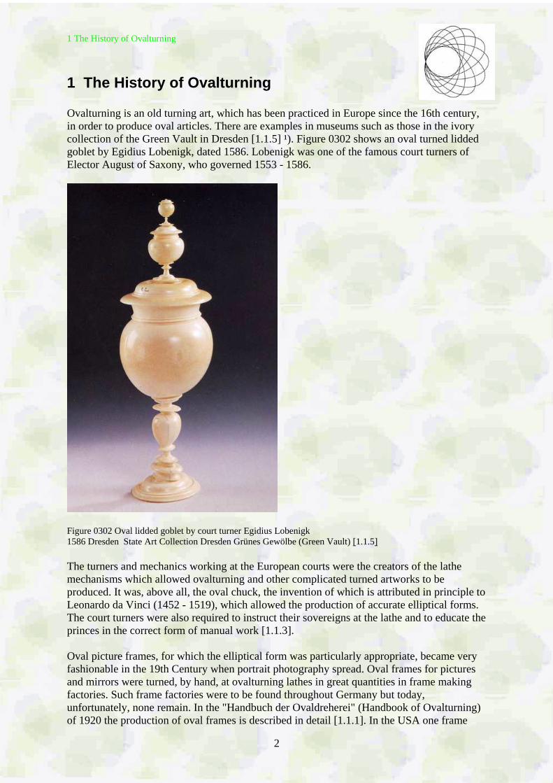
1 The History of Ovalturning Ovalturning is an old turning art, which has been practiced in Europe since the 16th century, in order to produce oval articles. There are examples in museums such as those in the ivory collection of the Green Vault in Dresden [1.1.5] ¹). Figure 0302 shows an oval turned lidded goblet by Egidius Lobenigk, dated 1586. Lobenigk was one of the famous court turners of Elector August of Saxony, who governed 1553 - 1586.
Figure 0302 Oval lidded goblet by court turner Egidius Lobenigk 1586 Dresden State Art Collection Dresden Grünes Gewölbe (Green Vault) [1.1.5] The turners and mechanics working at the European courts were the creators of the lathe mechanisms which allowed ovalturning and other complicated turned artworks to be produced. It was, above all, the oval chuck, the invention of which is attributed in principle to Leonardo da Vinci (1452 - 1519), which allowed the production of accurate elliptical forms. The court turners were also required to instruct their sovereigns at the lathe and to educate the princes in the correct form of manual work [1.1.3]. Oval picture frames, for which the elliptical form was particularly appropriate, became very fashionable in the 19th Century when portrait photography spread. Oval frames for pictures and mirrors were turned, by hand, at ovalturning lathes in great quantities in frame making factories. Such frame factories were to be found throughout Germany but today, unfortunately, none remain. In the "Handbuch der Ovaldreherei" (Handbook of Ovalturning) of 1920 the production of oval frames is described in detail [1.1.1]. In the USA one frame
1 The History of Ovalturning
3
factory, founded in 1864 by German immigrants, remains preserved as working museum [2.1.7] [2.2.1] [2.2.10] [2.2.12] [6.2]. One can study there the function of the ovalturning lathes of the 19th century. Since ovalturning required special skill the ovalturner was, among the turners, a well paid specialist. The ovalturning of frames disappeared from the workshops and factories when oval frames went out of fashion and particularly when faster milling machines were introduced. However, the variety of profiles obtained by ovalturning could not be achieved by milling. Although ovalturning has lost its importance as production technology today, it is of increasing interest to artisans, the restorer and for those turners who want to experience the stimulating characteristics of ovalturning. There are substantial differences between the use of hand tools when ovalturning compared to the tool use when plain (or circular) turning. There is only one specialist requirement for ovalturning, and that is the Oval Chuck. These chucks were commercially available until the 1950´s. Today these early chucks are only found by chance. Some individual turners have built themselves oval chucks based on old models. There is even an instruction to build an oval chuck from wood for study purposes [1.2.4]. Johannes Volmer, from Chemnitz/Saxony, has been involved with ovalturning and designing ovalturning devices and lathes since 1980. One of his prototypes was used by the Australian lathe manufacturer VICMARC [5.1]. Dan Bollinger in the USA [6.3] has built a variant of the Volmer lathes, and other turning suppliers are following. In March 2006 the craft supply Steinert / Germany presented the small ovalturning lathe picOval [5.4]. While the capacity of the classic oval chuck is limited by its imbalance and while its moving parts have to be constantly lubricated and maintained, these disadvantages are eliminated with the Volmer Ovalturning Lathes ODM (Ovaldrehmaschine) - which run smoothly at high speeds usual for turning wood. ¹) Numbers in [ ] refer to the bibliography (Literature)
2 What is Ovalturning
4
2 What is Ovalturning
2.1 Ovalturning Definition Ovalturning is the turning of a workpiece on a turning lathe provided with an oval chuck or on an ovalturning lathe. The turning tools were freely guided by hand. That applies generally to the turning of wood as with the normal (circular or plain) turning. When turning hard materials e.g. bone, ivory or soft stones (serpentine, alabaster, steatite) it may be necessary to clamp the turning tool in a compound slide rest. Turning tools are gouges and scrapers (profile ground) as used when woodturning. The use of routers or rotary cutters to produce a profile on an oval workpiece should not be called ovalturning but ovalmilling. When milling so called parallel curves of the ellipse are produced. They are not ellipses but regarded as ovals. When ovalturning, using the classic oval chuck, the workpieces have an exact elliptical cross-section. Therefore the name Ellipse Turning or Elliptical Turning would be acceptable. Since the ellipse is a symmetrical oval [2.2.5], the name ovalturning is also correct, and besides, this name has been used for centuries and is more easily pronounced.
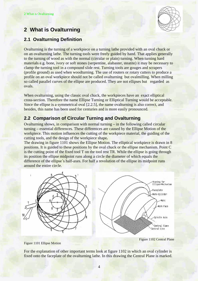
2.2 Comparison of Circular Turning and Ovalturning Ovalturning shows, in comparison with normal turning – in the following called circular turning – essential differences. These differences are caused by the Ellipse Motion of the workpiece. This motion influences the cutting of the workpiece material, the guiding of the cutting tools, and the design of the workpiece shape. The drawing in figure 1101 shows the Ellipse Motion. The elliptical workpiece is drawn in 8 positions. It is guided to these positions by the oval chuck or the ellipse mechanism. Point C is the cutting point of the fixed tool T on the tool rest TR. While the ellipse is going through its position the ellipse midpoint runs along a circle the diameter of which equals the difference of the ellipse´s half-axes. For half a revolution of the ellipse its midpoint runs around the entire circle.
Figure 1102 Central Plane Figure 1101 Ellipse Motion For the explanation of other important terms look at figure 1102 in which an oval cylinder is fixed onto the faceplate of the ovalturning lathe. In this drawing the Central Plane is marked.
2 What is Ovalturning
5
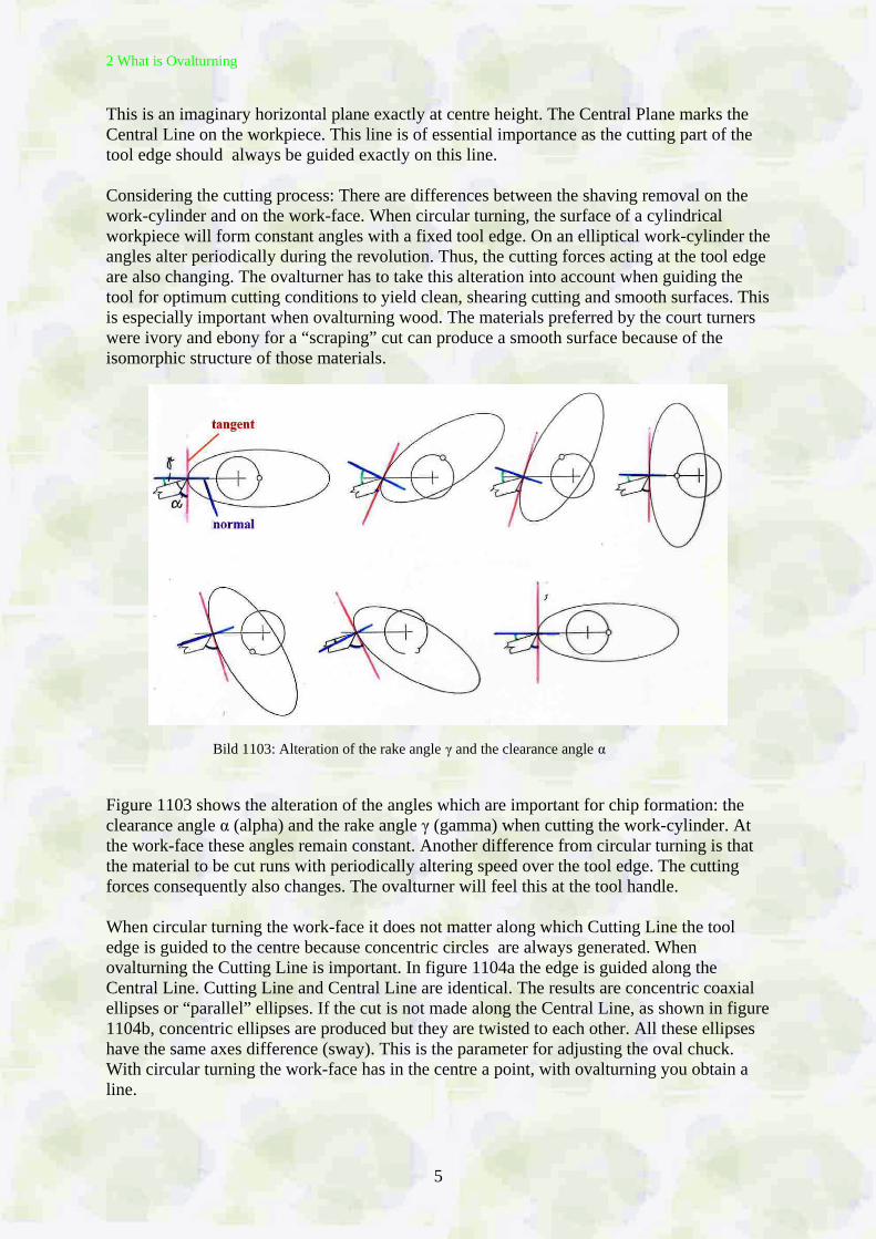
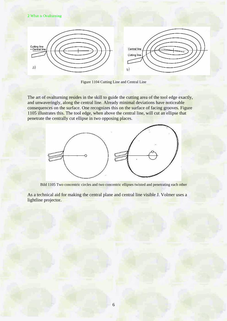
This is an imaginary horizontal plane exactly at centre height. The Central Plane marks the Central Line on the workpiece. This line is of essential importance as the cutting part of the tool edge should always be guided exactly on this line. Considering the cutting process: There are differences between the shaving removal on the work-cylinder and on the work-face. When circular turning, the surface of a cylindrical workpiece will form constant angles with a fixed tool edge. On an elliptical work-cylinder the angles alter periodically during the revolution. Thus, the cutting forces acting at the tool edge are also changing. The ovalturner has to take this alteration into account when guiding the tool for optimum cutting conditions to yield clean, shearing cutting and smooth surfaces. This is especially important when ovalturning wood. The materials preferred by the court turners were ivory and ebony for a “scraping” cut can produce a smooth surface because of the isomorphic structure of those materials. Bild 1103: Alteration of the rake angle γ and the clearance angle α Figure 1103 shows the alteration of the angles which are important for chip formation: the clearance angle α (alpha) and the rake angle γ (gamma) when cutting the work-cylinder. At the work-face these angles remain constant. Another difference from circular turning is that the material to be cut runs with periodically altering speed over the tool edge. The cutting forces consequently also changes. The ovalturner will feel this at the tool handle. When circular turning the work-face it does not matter along which Cutting Line the tool edge is guided to the centre because concentric circles are always generated. When ovalturning the Cutting Line is important. In figure 1104a the edge is guided along the Central Line. Cutting Line and Central Line are identical. The results are concentric coaxial ellipses or “parallel” ellipses. If the cut is not made along the Central Line, as shown in figure 1104b, concentric ellipses are produced but they are twisted to each other. All these ellipses have the same axes difference (sway). This is the parameter for adjusting the oval chuck. With circular turning the work-face has in the centre a point, with ovalturning you obtain a line.
2 What is Ovalturning
6
Figure 1104 Cutting Line and Central Line The art of ovalturning resides in the skill to guide the cutting area of the tool edge exactly, and unwaveringly, along the central line. Already minimal deviations have noticeable consequences on the surface. One recognizes this on the surface of facing grooves. Figure 1105 illustrates this. The tool edge, when above the central line, will cut an ellipse that penetrate the centrally cut ellipse in two opposing places.
Bild 1105 Two concentric circles and two concentric ellipses twisted and penetrating each other As a technical aid for making the central plane and central line visible J. Volmer uses a lightline projector.
3 Ellipses Geometry
7
3 Ellipse-Geometry The ovalturner should know at least the following about ellipses from his school books.
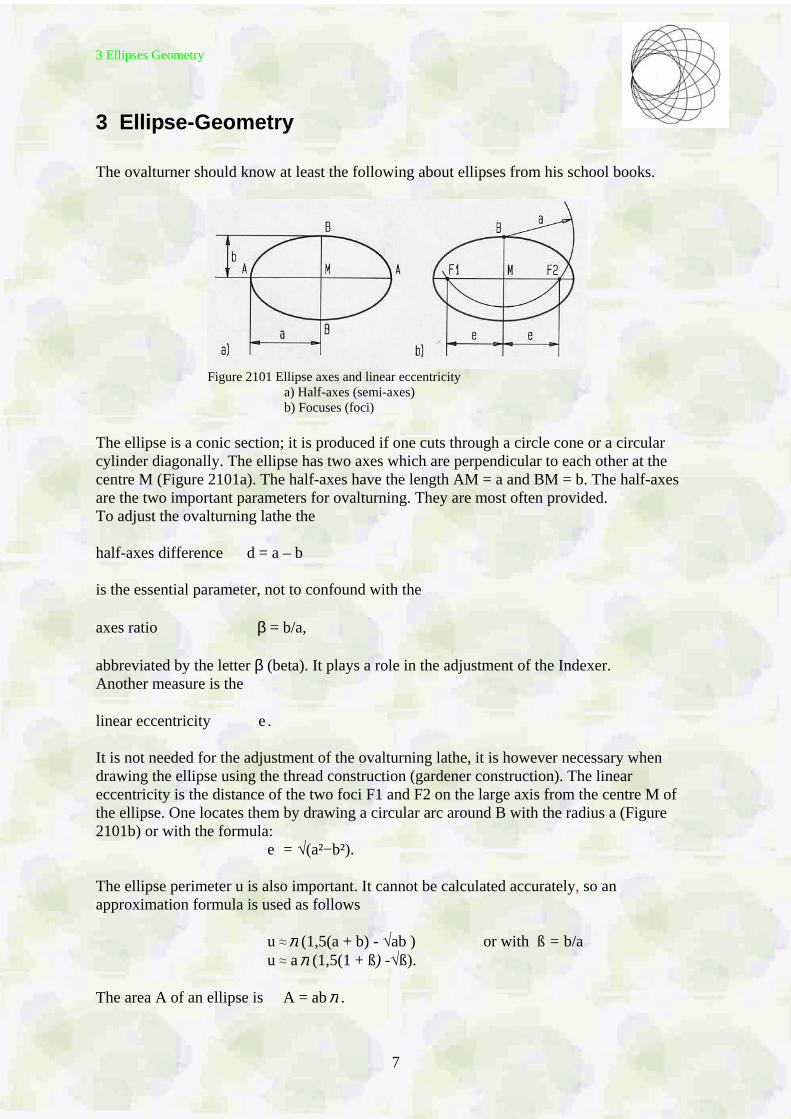
Figure 2101 Ellipse axes and linear eccentricity a) Half-axes (semi-axes) b) Focuses (foci) The ellipse is a conic section; it is produced if one cuts through a circle cone or a circular cylinder diagonally. The ellipse has two axes which are perpendicular to each other at the centre M (Figure 2101a). The half-axes have the length AM = a and BM = b. The half-axes are the two important parameters for ovalturning. They are most often provided. To adjust the ovalturning lathe the half-axes difference d = a – b is the essential parameter, not to confound with the axes ratio β = b/a, abbreviated by the letter β (beta). It plays a role in the adjustment of the Indexer. Another measure is the linear eccentricity e. It is not needed for the adjustment of the ovalturning lathe, it is however necessary when drawing the ellipse using the thread construction (gardener construction). The linear eccentricity is the distance of the two foci F1 and F2 on the large axis from the centre M of the ellipse. One locates them by drawing a circular arc around B with the radius a (Figure 2101b) or with the formula: e = √(a²−b²). The ellipse perimeter u is also important. It cannot be calculated accurately, so an approximation formula is used as follows u ≈π (1,5(a + b) - √ab ) or with ß = b/a u ≈ aπ (1,5(1 + ß) -√ß). The area A of an ellipse is A = abπ .
3 Ellipses Geometry
8
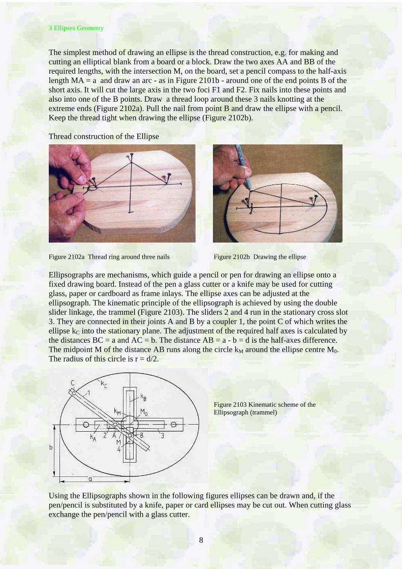
The simplest method of drawing an ellipse is the thread construction, e.g. for making and cutting an elliptical blank from a board or a block. Draw the two axes AA and BB of the required lengths, with the intersection M, on the board, set a pencil compass to the half-axis length MA = a and draw an arc - as in Figure 2101b - around one of the end points B of the short axis. It will cut the large axis in the two foci F1 and F2. Fix nails into these points and also into one of the B points. Draw a thread loop around these 3 nails knotting at the extreme ends (Figure 2102a). Pull the nail from point B and draw the ellipse with a pencil. Keep the thread tight when drawing the ellipse (Figure 2102b). Thread construction of the Ellipse
Figure 2102a Thread ring around three nails Figure 2102b Drawing the ellipse Ellipsographs are mechanisms, which guide a pencil or pen for drawing an ellipse onto a fixed drawing board. Instead of the pen a glass cutter or a knife may be used for cutting glass, paper or cardboard as frame inlays. The ellipse axes can be adjusted at the ellipsograph. The kinematic principle of the ellipsograph is achieved by using the double slider linkage, the trammel (Figure 2103). The sliders 2 and 4 run in the stationary cross slot 3. They are connected in their joints A and B by a coupler 1, the point C of which writes the ellipse kC into the stationary plane. The adjustment of the required half axes is calculated by the distances BC = a and AC = b. The distance AB = a - b = d is the half-axes difference. The midpoint M of the distance AB runs along the circle kM around the ellipse centre M0. The radius of this circle is r = d/2.
Figure 2103 Kinematic scheme of the Ellipsograph (trammel)
Using the Ellipsographs shown in the following figures ellipses can be drawn and, if the pen/pencil is substituted by a knife, paper or card ellipses may be cut out. When cutting glass exchange the pen/pencil with a glass cutter.
3 Ellipses Geometry
9
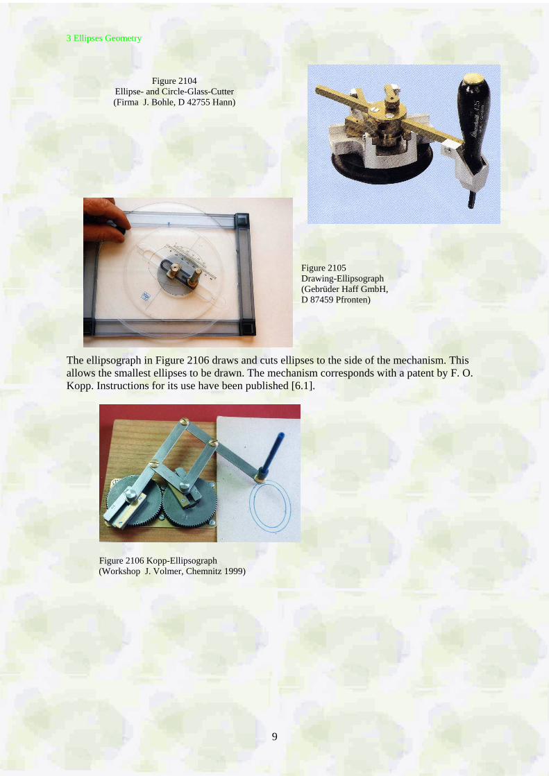
Figure 2104
Ellipse- and Circle-Glass-Cutter (Firma J. Bohle, D 42755 Hann)
Figure 2105 Drawing-Ellipsograph (Gebrüder Haff GmbH, D 87459 Pfronten)
The ellipsograph in Figure 2106 draws and cuts ellipses to the side of the mechanism. This allows the smallest ellipses to be drawn. The mechanism corresponds with a patent by F. O. Kopp. Instructions for its use have been published [6.1].
Figure 2106 Kopp-Ellipsograph
(Workshop J. Volmer, Chemnitz 1999)
4 Oval Chuck and Ovalturning Lathes
10
4 Oval Chuck and Ovalturning Lathes
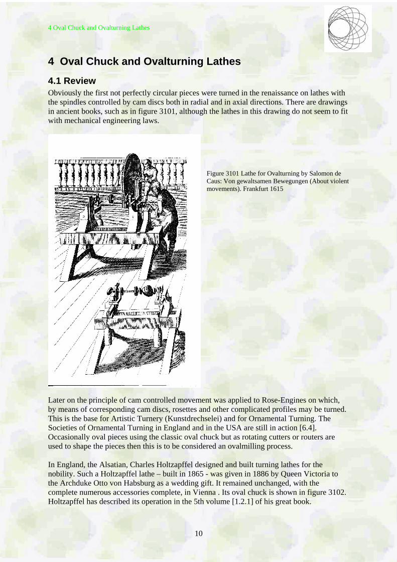
4.1 Review Obviously the first not perfectly circular pieces were turned in the renaissance on lathes with the spindles controlled by cam discs both in radial and in axial directions. There are drawings in ancient books, such as in figure 3101, although the lathes in this drawing do not seem to fit with mechanical engineering laws.
Figure 3101 Lathe for Ovalturning by Salomon de Caus: Von gewaltsamen Bewegungen (About violent movements). Frankfurt 1615
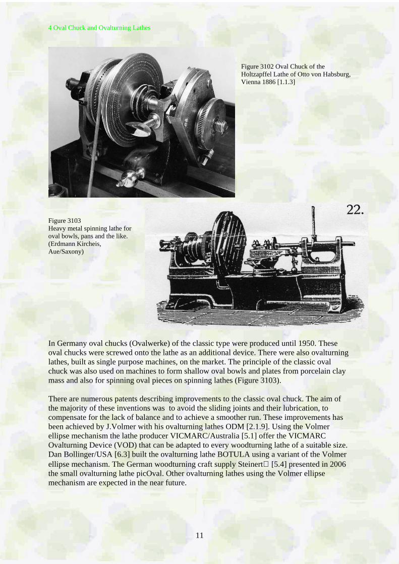
Later on the principle of cam controlled movement was applied to Rose-Engines on which, by means of corresponding cam discs, rosettes and other complicated profiles may be turned. This is the base for Artistic Turnery (Kunstdrechselei) and for Ornamental Turning. The Societies of Ornamental Turning in England and in the USA are still in action [6.4]. Occasionally oval pieces using the classic oval chuck but as rotating cutters or routers are used to shape the pieces then this is to be considered an ovalmilling process. In England, the Alsatian, Charles Holtzapffel designed and built turning lathes for the nobility. Such a Holtzapffel lathe – built in 1865 - was given in 1886 by Queen Victoria to the Archduke Otto von Habsburg as a wedding gift. It remained unchanged, with the complete numerous accessories complete, in Vienna . Its oval chuck is shown in figure 3102. Holtzapffel has described its operation in the 5th volume [1.2.1] of his great book.
4 Oval Chuck and Ovalturning Lathes
11
Figure 3102 Oval Chuck of the Holtzapffel Lathe of Otto von Habsburg, Vienna 1886 [1.1.3]
Figure 3103 Heavy metal spinning lathe for oval bowls, pans and the like. (Erdmann Kircheis, Aue/Saxony) In Germany oval chucks (Ovalwerke) of the classic type were produced until 1950. These oval chucks were screwed onto the lathe as an additional device. There were also ovalturning lathes, built as single purpose machines, on the market. The principle of the classic oval chuck was also used on machines to form shallow oval bowls and plates from porcelain clay mass and also for spinning oval pieces on spinning lathes (Figure 3103). There are numerous patents describing improvements to the classic oval chuck. The aim of the majority of these inventions was to avoid the sliding joints and their lubrication, to compensate for the lack of balance and to achieve a smoother run. These improvements has been achieved by J.Volmer with his ovalturning lathes ODM [2.1.9]. Using the Volmer ellipse mechanism the lathe producer VICMARC/Australia [5.1] offer the VICMARC Ovalturning Device (VOD) that can be adapted to every woodturning lathe of a suitable size. Dan Bollinger/USA [6.3] built the ovalturning lathe BOTULA using a variant of the Volmer ellipse mechanism. The German woodturning craft supply Steinert [5.4] presented in 2006 the small ovalturning lathe picOval. Other ovalturning lathes using the Volmer ellipse mechanism are expected in the near future.
4 Oval Chuck and Ovalturning Lathes
12
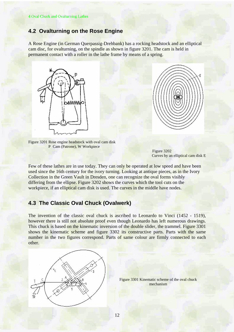
4.2 Ovalturning on the Rose Engine A Rose Engine (in German Querpassig-Drehbank) has a rocking headstock and an elliptical cam disc, for ovalturning, on the spindle as shown in figure 3201. The cam is held in permanent contact with a roller in the lathe frame by means of a spring.
Figure 3201 Rose engine headstock with oval cam disk P Cam (Patrone), W Workpiece Figure 3202
Curves by an elliptical cam disk E Few of these lathes are in use today. They can only be operated at low speed and have been used since the 16th century for the ivory turning. Looking at antique pieces, as in the Ivory Collection in the Green Vault in Dresden, one can recognize the oval forms visibly differing from the ellipse. Figure 3202 shows the curves which the tool cuts on the workpiece, if an elliptical cam disk is used. The curves in the middle have nodes.
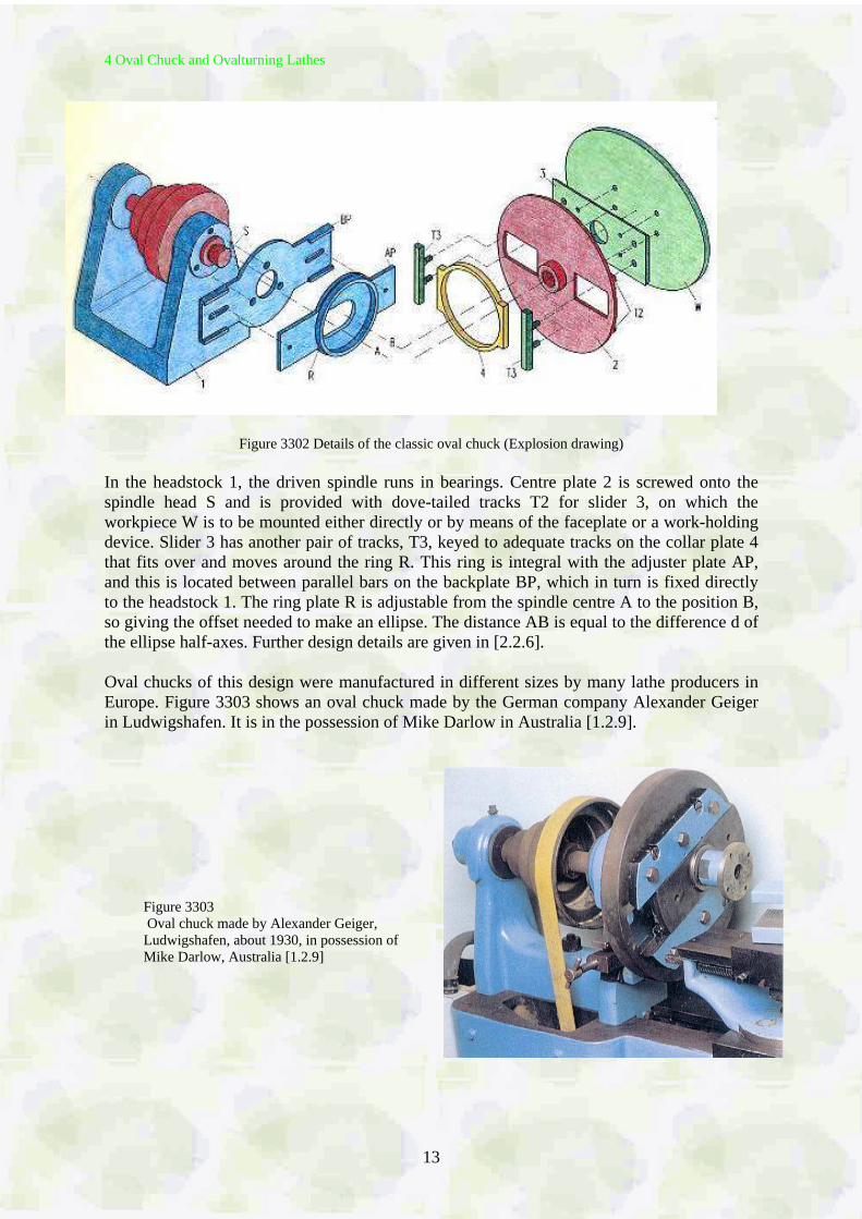
4.3 The Classic Oval Chuck (Ovalwerk) The invention of the classic oval chuck is ascribed to Leonardo to Vinci (1452 - 1519), however there is still not absolute proof even though Leonardo has left numerous drawings. This chuck is based on the kinematic inversion of the double slider, the trammel. Figure 3301 shows the kinematic scheme and figure 3302 its constructive parts. Parts with the same number in the two figures correspond. Parts of same colour are firmly connected to each other.
Figure 3301 Kinematic scheme of the oval chuck mechanism
4 Oval Chuck and Ovalturning Lathes
13
Figure 3302 Details of the classic oval chuck (Explosion drawing)
In the headstock 1, the driven spindle runs in bearings. Centre plate 2 is screwed onto the spindle head S and is provided with dove-tailed tracks T2 for slider 3, on which the workpiece W is to be mounted either directly or by means of the faceplate or a work-holding device. Slider 3 has another pair of tracks, T3, keyed to adequate tracks on the collar plate 4 that fits over and moves around the ring R. This ring is integral with the adjuster plate AP, and this is located between parallel bars on the backplate BP, which in turn is fixed directly to the headstock 1. The ring plate R is adjustable from the spindle centre A to the position B, so giving the offset needed to make an ellipse. The distance AB is equal to the difference d of the ellipse half-axes. Further design details are given in [2.2.6]. Oval chucks of this design were manufactured in different sizes by many lathe producers in Europe. Figure 3303 shows an oval chuck made by the German company Alexander Geiger in Ludwigshafen. It is in the possession of Mike Darlow in Australia [1.2.9].
Figure 3303 Oval chuck made by Alexander Geiger, Ludwigshafen, about 1930, in possession of Mike Darlow, Australia [1.2.9]
4 Oval Chuck and Ovalturning Lathes
14
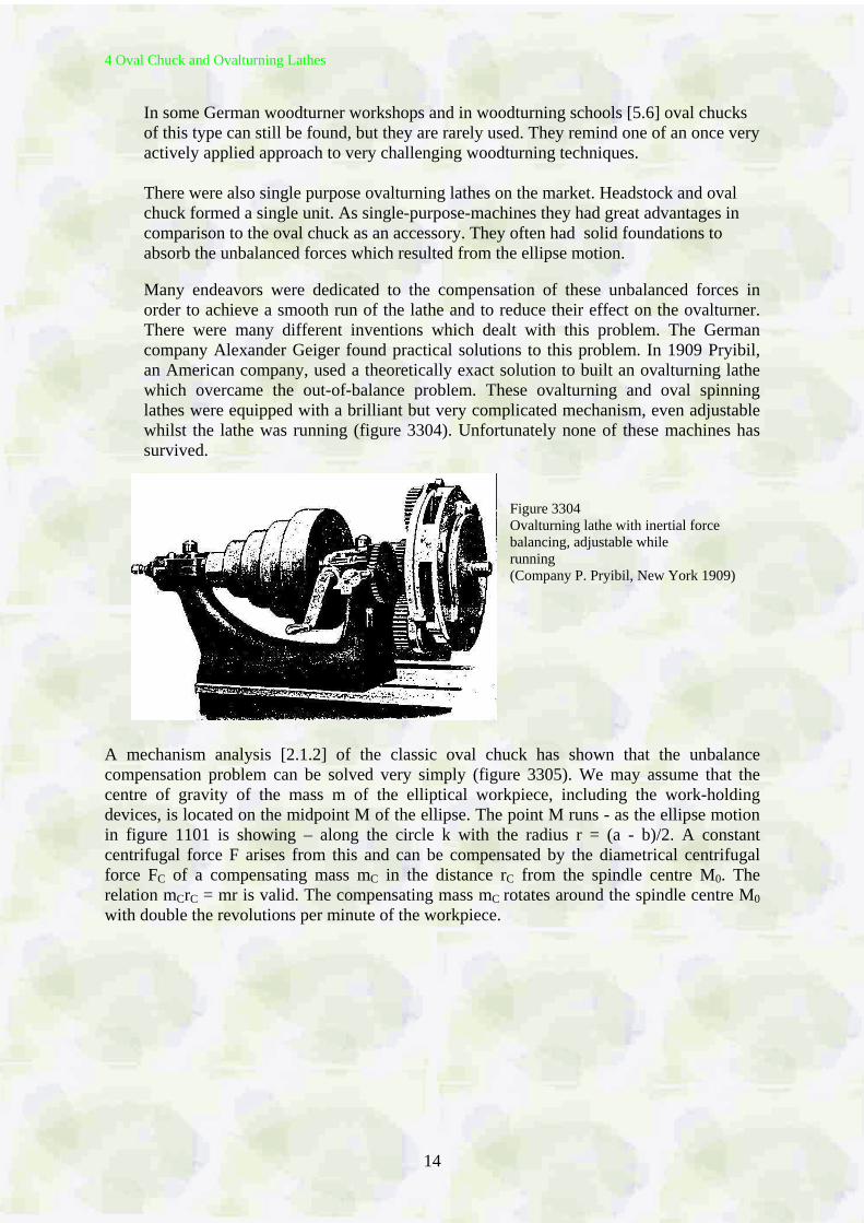
In some German woodturner workshops and in woodturning schools [5.6] oval chucks of this type can still be found, but they are rarely used. They remind one of an once very actively applied approach to very challenging woodturning techniques. There were also single purpose ovalturning lathes on the market. Headstock and oval chuck formed a single unit. As single-purpose-machines they had great advantages in comparison to the oval chuck as an accessory. They often had solid foundations to absorb the unbalanced forces which resulted from the ellipse motion. Many endeavors were dedicated to the compensation of these unbalanced forces in order to achieve a smooth run of the lathe and to reduce their effect on the ovalturner. There were many different inventions which dealt with this problem. The German company Alexander Geiger found practical solutions to this problem. In 1909 Pryibil, an American company, used a theoretically exact solution to built an ovalturning lathe which overcame the out-of-balance problem. These ovalturning and oval spinning lathes were equipped with a brilliant but very complicated mechanism, even adjustable whilst the lathe was running (figure 3304). Unfortunately none of these machines has survived.
Figure 3304 Ovalturning lathe with inertial force balancing, adjustable while running (Company P. Pryibil, New York 1909)
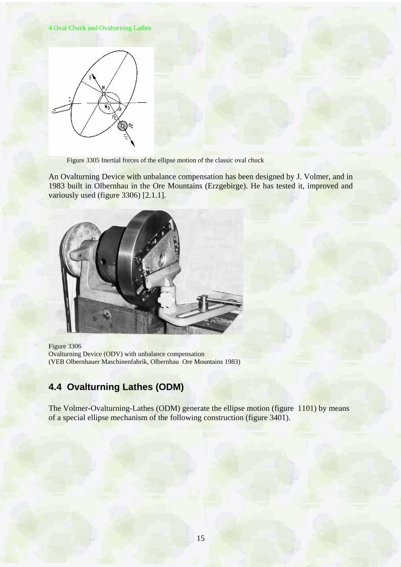
A mechanism analysis [2.1.2] of the classic oval chuck has shown that the unbalance compensation problem can be solved very simply (figure 3305). We may assume that the centre of gravity of the mass m of the elliptical workpiece, including the work-holding devices, is located on the midpoint M of the ellipse. The point M runs - as the ellipse motion in figure 1101 is showing – along the circle k with the radius r = (a - b)/2. A constant centrifugal force F arises from this and can be compensated by the diametrical centrifugal force FC of a compensating mass mC in the distance rC from the spindle centre M0. The relation mCrC = mr is valid. The compensating mass mC rotates around the spindle centre M0 with double the revolutions per minute of the workpiece.
4 Oval Chuck and Ovalturning Lathes
15
Figure 3305 Inertial forces of the ellipse motion of the classic oval chuck
An Ovalturning Device with unbalance compensation has been designed by J. Volmer, and in 1983 built in Olbernhau in the Ore Mountains (Erzgebirge). He has tested it, improved and variously used (figure 3306) [2.1.1].
Figure 3306 Ovalturning Device (ODV) with unbalance compensation (VEB Olbernhauer Maschinenfabrik, Olbernhau Ore Mountains 1983)
4.4 Ovalturning Lathes (ODM) The Volmer-Ovalturning-Lathes (ODM) generate the ellipse motion (figure 1101) by means of a special ellipse mechanism of the following construction (figure 3401).
4 Oval Chuck and Ovalturning Lathes
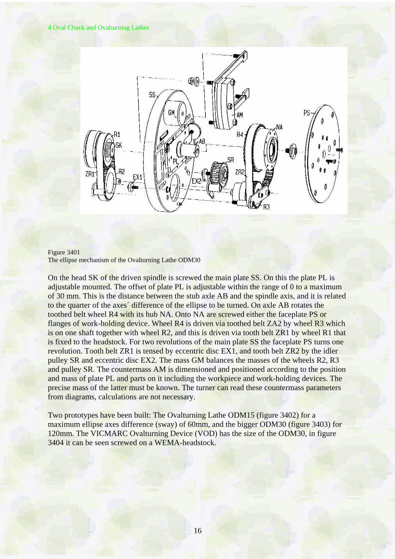
16
Figure 3401 The ellipse mechanism of the Ovalturning Lathe ODM30 On the head SK of the driven spindle is screwed the main plate SS. On this the plate PL is adjustable mounted. The offset of plate PL is adjustable within the range of 0 to a maximum of 30 mm. This is the distance between the stub axle AB and the spindle axis, and it is related to the quarter of the axes´ difference of the ellipse to be turned. On axle AB rotates the toothed belt wheel R4 with its hub NA. Onto NA are screwed either the faceplate PS or flanges of work-holding device. Wheel R4 is driven via toothed belt ZA2 by wheel R3 which is on one shaft together with wheel R2, and this is driven via tooth belt ZR1 by wheel R1 that is fixed to the headstock. For two revolutions of the main plate SS the faceplate PS turns one revolution. Tooth belt ZR1 is tensed by eccentric disc EX1, and tooth belt ZR2 by the idler pulley SR and eccentric disc EX2. The mass GM balances the masses of the wheels R2, R3 and pulley SR. The countermass AM is dimensioned and positioned according to the position and mass of plate PL and parts on it including the workpiece and work-holding devices. The precise mass of the latter must be known. The turner can read these countermass parameters from diagrams, calculations are not necessary. Two prototypes have been built: The Ovalturning Lathe ODM15 (figure 3402) for a maximum ellipse axes difference (sway) of 60mm, and the bigger ODM30 (figure 3403) for 120mm. The VICMARC Ovalturning Device (VOD) has the size of the ODM30, in figure 3404 it can be seen screwed on a WEMA-headstock.
4 Oval Chuck and Ovalturning Lathes
17
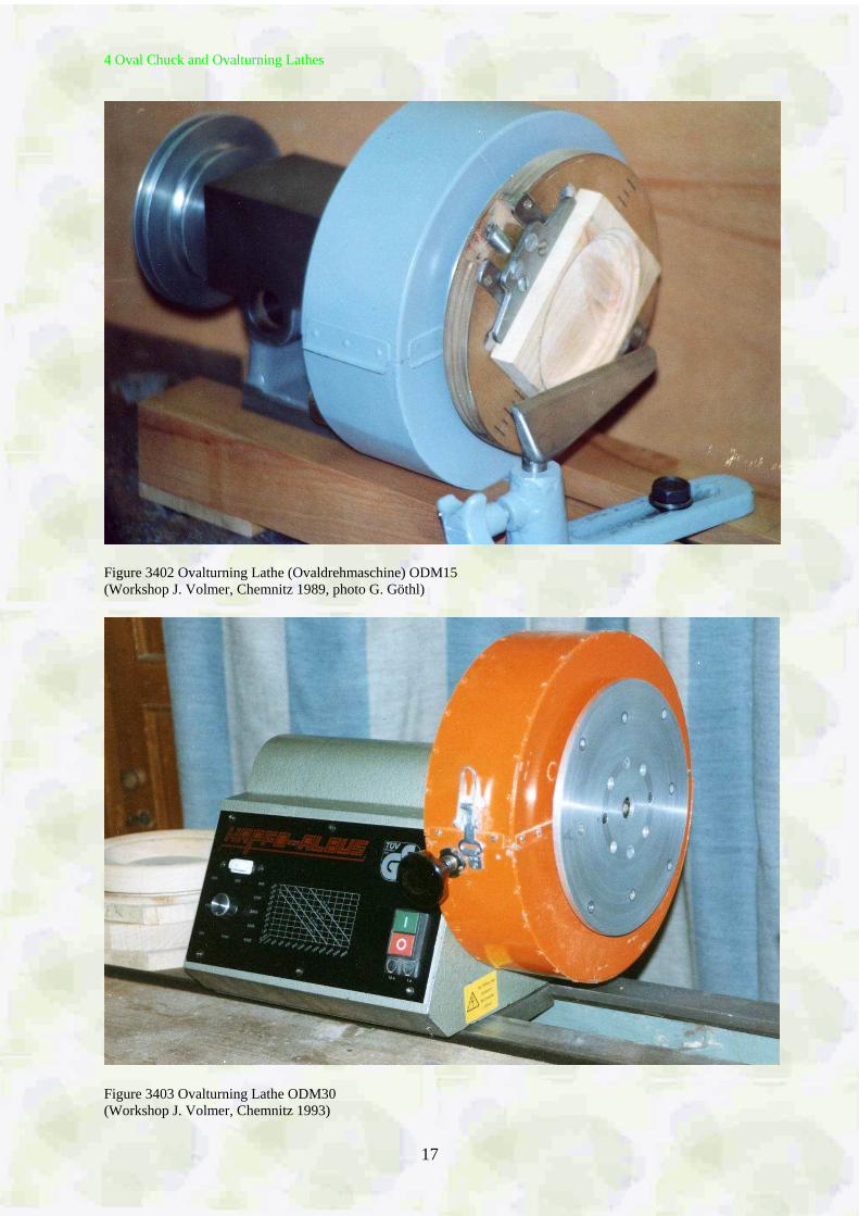
Figure 3402 Ovalturning Lathe (Ovaldrehmaschine) ODM15 (Workshop J. Volmer, Chemnitz 1989, photo G. Göthl)
Figure 3403 Ovalturning Lathe ODM30 (Workshop J. Volmer, Chemnitz 1993)
4 Oval Chuck and Ovalturning Lathes
18
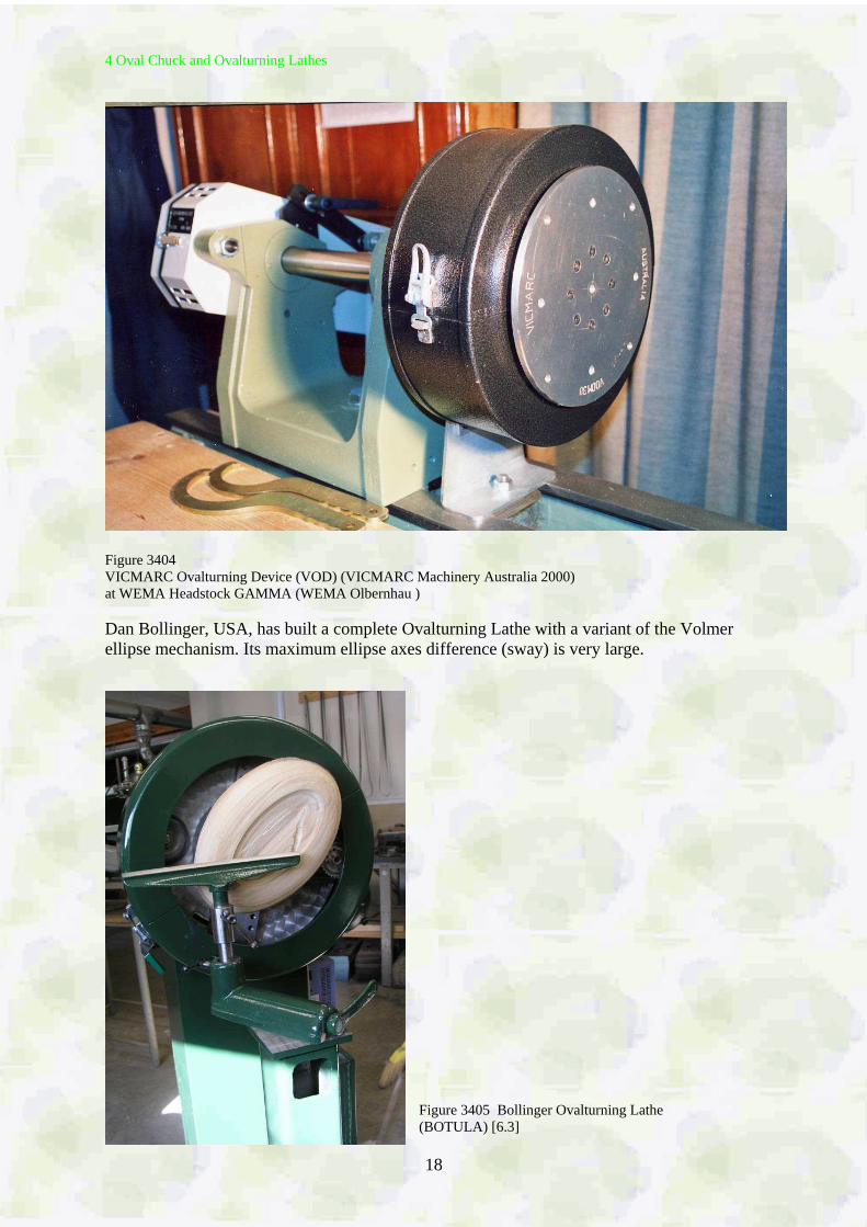
Figure 3404 VICMARC Ovalturning Device (VOD) (VICMARC Machinery Australia 2000) at WEMA Headstock GAMMA (WEMA Olbernhau ) Dan Bollinger, USA, has built a complete Ovalturning Lathe with a variant of the Volmer ellipse mechanism. Its maximum ellipse axes difference (sway) is very large.
Figure 3405 Bollinger Ovalturning Lathe (BOTULA) [6.3]
4 Oval Chuck and Ovalturning Lathes
19
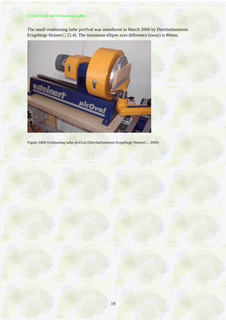
The small ovalturning lathe picOval was introduced in March 2006 by Drechselzentrum Erzgebirge Steinert [5.4]. The maximum ellipse axes difference (sway) is 80mm.
Figure 3406 Ovalturning lathe picOval (Drechselzentrum Erzgebirge Steinert, 2006)
5 Work-Holding
20
5 Work-Holding
5.1 General Conditions For chucking blanks, and pieces completely oval turned at one side, onto the ovalturning lathe there is a variety of holding and chucking devices, among them chucks which are used for normal (circular) turning. But, take note, the screw chuck used for holding circular facework is strictly forbidden when oval turning as it does not hold the blank safely in its position. The blank can twist, and this is extremely dangerous. Any movement of the workpiece from its starting position must be absolutely avoided. When circular turning one can rotate the workpiece within loose chuck jaws, with an oval workpiece this is not possible. The workpiece must remain in the chuck in the same position from the very beginning. The new ovalturning lathes allow to be rotated the chucked workpiece together with the chuck or the faceplate. Work-holding devices should be as light as possible due to the unbalance forces when ovalturning. Wooden parts are preferred. One should choose the lightest types of steel chucks. The workpiece should be held as close to the faceplate as possible. Overhanging workpieces cause vibrations and consequently no cleanly cut surfaces.
5.2 Screwing on
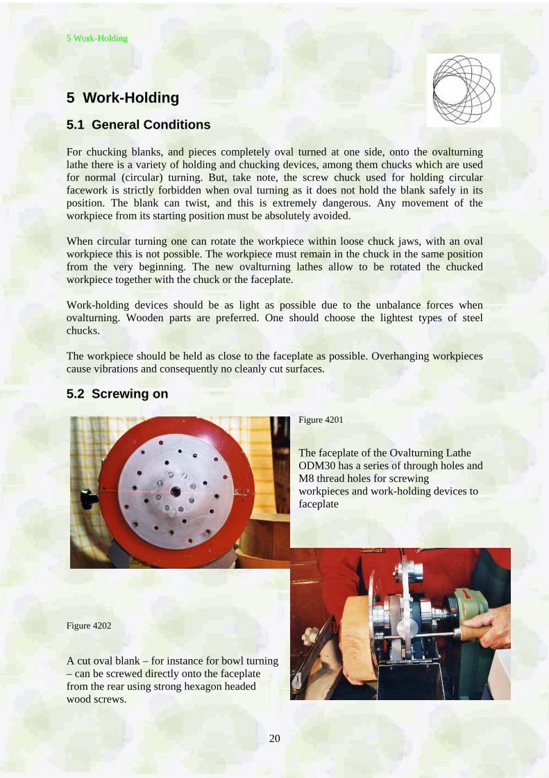
Figure 4201 The faceplate of the Ovalturning Lathe ODM30 has a series of through holes and M8 thread holes for screwing workpieces and work-holding devices to faceplate
Figure 4202 A cut oval blank – for instance for bowl turning – can be screwed directly onto the faceplate from the rear using strong hexagon headed wood screws.
5 Work-Holding
21
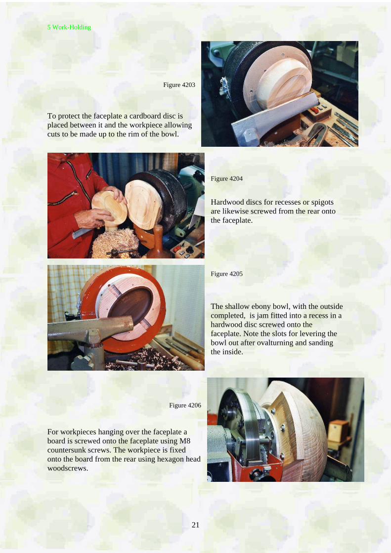
Figure 4203 To protect the faceplate a cardboard disc is placed between it and the workpiece allowing cuts to be made up to the rim of the bowl.
Figure 4204 Hardwood discs for recesses or spigots are likewise screwed from the rear onto the faceplate. Figure 4205 The shallow ebony bowl, with the outside completed, is jam fitted into a recess in a hardwood disc screwed onto the faceplate. Note the slots for levering the bowl out after ovalturning and sanding the inside.
Figure 4206 For workpieces hanging over the faceplate a board is screwed onto the faceplate using M8 countersunk screws. The workpiece is fixed onto the board from the rear using hexagon head woodscrews.
5 Work-Holding
22
Figure 4207 Flat light blanks to be turned completely only from the front, as with shallow bowls, are glued with paper onto a board which is then screwed from the rear onto the faceplate.
5.3 Chucks
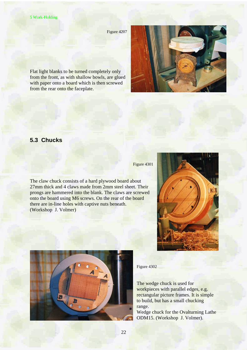
Figure 4301 The claw chuck consists of a hard plywood board about 27mm thick and 4 claws made from 2mm steel sheet. Their prongs are hammered into the blank. The claws are screwed onto the board using M6 screws. On the rear of the board there are in-line holes with captive nuts beneath. (Workshop J. Volmer)
Figure 4302 The wedge chuck is used for workpieces with parallel edges, e.g. rectangular picture frames. It is simple to build, but has a small chucking range. Wedge chuck for the Ovalturning Lathe ODM15. (Workshop J. Volmer).
5 Work-Holding
23
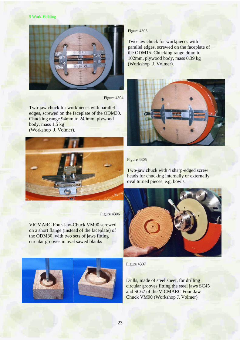
Figure 4303 Two-jaw chuck for workpieces with parallel edges, screwed on the faceplate of the ODM15. Chucking range 9mm to 102mm, plywood body, mass 0,39 kg (Workshop J. Volmer).
Figure 4304
Two-jaw chuck for workpieces with parallel edges, screwed on the faceplate of the ODM30. Chucking range 94mm to 240mm, plywood body, mass 1,5 kg (Workshop J. Volmer).
Figure 4305 Two-jaw chuck with 4 sharp-edged screw heads for chucking internally or externally oval turned pieces, e.g. bowls.
Figure 4306 VICMARC Four-Jaw-Chuck VM90 screwed on a short flange (instead of the faceplate) of the ODM30, with two sets of jaws fitting circular grooves in oval sawed blanks
Figure 4307 Drills, made of steel sheet, for drilling circular grooves fitting the steel jaws SC45 and SC67 of the VICMARC Four-Jaw-Chuck VM90 (Workshop J. Volmer)
5 Work-Holding
24
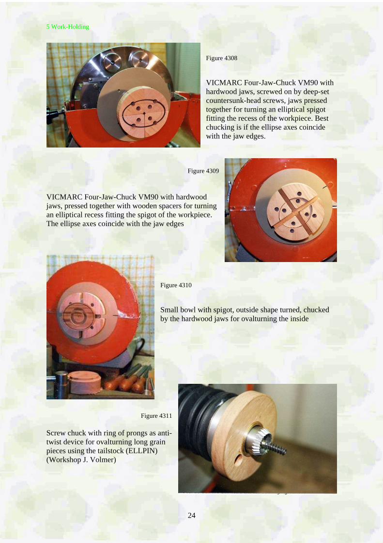
Figure 4308 VICMARC Four-Jaw-Chuck VM90 with hardwood jaws, screwed on by deep-set countersunk-head screws, jaws pressed together for turning an elliptical spigot fitting the recess of the workpiece. Best chucking is if the ellipse axes coincide with the jaw edges.
Figure 4309 VICMARC Four-Jaw-Chuck VM90 with hardwood jaws, pressed together with wooden spacers for turning an elliptical recess fitting the spigot of the workpiece. The ellipse axes coincide with the jaw edges
Figure 4310 Small bowl with spigot, outside shape turned, chucked by the hardwood jaws for ovalturning the inside
Figure 4311
Screw chuck with ring of prongs as anti-twist device for ovalturning long grain pieces using the tailstock (ELLPIN) (Workshop J. Volmer)
6 Methods of Ovalturning
25
6 Methods of Ovalturning
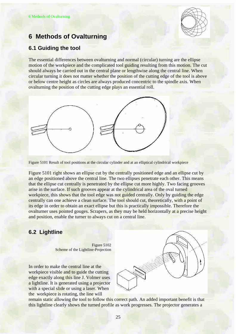
6.1 Guiding the tool The essential differences between ovalturning and normal (circular) turning are the ellipse motion of the workpiece and the complicated tool guiding resulting from this motion. The cut should always be carried out in the central plane or lengthwise along the central line. When circular turning it does not matter whether the position of the cutting edge of the tool is above or below centre height as circles are always produced concentric to the spindle axis. When ovalturning the position of the cutting edge plays an essential roll.
Figure 5101 Result of tool positions at the circular cylinder and at an elliptical cylindrical workpiece Figure 5101 right shows an ellipse cut by the centrally positioned edge and an ellipse cut by an edge positioned above the central line. The two ellipses penetrate each other. This means that the ellipse cut centrally is penetrated by the ellipse cut more highly. Two facing grooves arise in the surface. If such grooves appear at the cylindrical area of the oval turned workpiece, this shows that the tool edge was not guided centrally. Only by guiding the edge centrally can one achieve a clean surface. The tool should cut, theoretically, with a point of its edge in order to obtain an exact ellipse but this is practically impossible. Therefore the ovalturner uses pointed gouges. Scrapers, as they may be held horizontally at a precise height and position, enable the turner to always cut on a central line.
6.2 Lightline
Figure 5102 Scheme of the Lightline-Projection
In order to make the central line at the workpiece visible and to guide the cutting edge exactly along this line J. Volmer uses a lightline. It is generated using a projector with a special slide or using a laser. When the workpiece is rotating, the line will remain static allowing the tool to follow this correct path. An added important benefit is that this lightline clearly shows the turned profile as work progresses. The projector generates a
6 Methods of Ovalturning
26
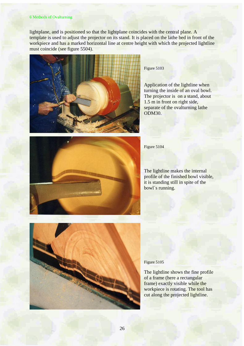
lightplane, and is positioned so that the lightplane coincides with the central plane. A template is used to adjust the projector on its stand. It is placed on the lathe bed in front of the workpiece and has a marked horizontal line at centre height with which the projected lightline must coincide (see figure 5504).
Figure 5103 Application of the lightline when turning the inside of an oval bowl. The projector is on a stand, about 1.5 m in front on right side, separate of the ovalturning lathe ODM30. Figure 5104 The lightline makes the internal profile of the finished bowl visible, it is standing still in spite of the bowl´s running.
Figure 5105 The lightline shows the fine profile of a frame (here a rectangular frame) exactly visible while the workpiece is rotating. The tool has cut along the projected lightline.
6 Methods of Ovalturning
27
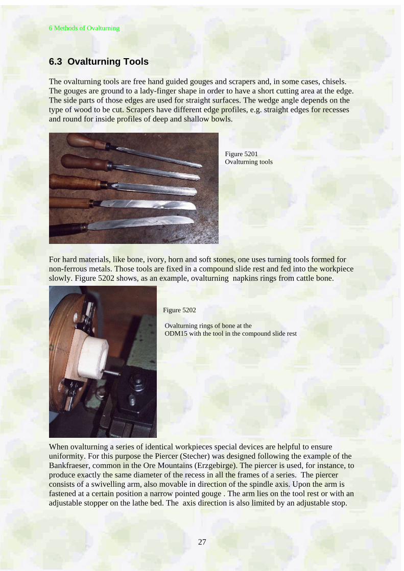
6.3 Ovalturning Tools The ovalturning tools are free hand guided gouges and scrapers and, in some cases, chisels. The gouges are ground to a lady-finger shape in order to have a short cutting area at the edge. The side parts of those edges are used for straight surfaces. The wedge angle depends on the type of wood to be cut. Scrapers have different edge profiles, e.g. straight edges for recesses and round for inside profiles of deep and shallow bowls.
Figure 5201 Ovalturning tools
For hard materials, like bone, ivory, horn and soft stones, one uses turning tools formed for non-ferrous metals. Those tools are fixed in a compound slide rest and fed into the workpiece slowly. Figure 5202 shows, as an example, ovalturning napkins rings from cattle bone.
Figure 5202 Ovalturning rings of bone at the ODM15 with the tool in the compound slide rest
When ovalturning a series of identical workpieces special devices are helpful to ensure uniformity. For this purpose the Piercer (Stecher) was designed following the example of the Bankfraeser, common in the Ore Mountains (Erzgebirge). The piercer is used, for instance, to produce exactly the same diameter of the recess in all the frames of a series. The piercer consists of a swivelling arm, also movable in direction of the spindle axis. Upon the arm is fastened at a certain position a narrow pointed gouge . The arm lies on the tool rest or with an adjustable stopper on the lathe bed. The axis direction is also limited by an adjustable stop.
6 Methods of Ovalturning
28
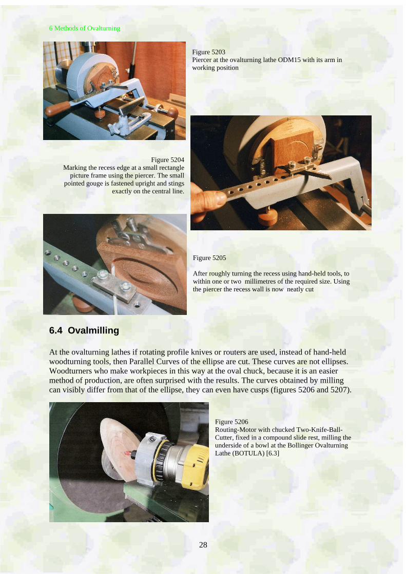
Figure 5203 Piercer at the ovalturning lathe ODM15 with its arm in working position
Figure 5204 Marking the recess edge at a small rectangle
picture frame using the piercer. The small pointed gouge is fastened upright and stings
exactly on the central line.
Figure 5205 After roughly turning the recess using hand-held tools, to within one or two millimetres of the required size. Using the piercer the recess wall is now neatly cut
6.4 Ovalmilling At the ovalturning lathes if rotating profile knives or routers are used, instead of hand-held woodturning tools, then Parallel Curves of the ellipse are cut. These curves are not ellipses. Woodturners who make workpieces in this way at the oval chuck, because it is an easier method of production, are often surprised with the results. The curves obtained by milling can visibly differ from that of the ellipse, they can even have cusps (figures 5206 and 5207).
Figure 5206 Routing-Motor with chucked Two-Knife-Ball-Cutter, fixed in a compound slide rest, milling the underside of a bowl at the Bollinger Ovalturning Lathe (BOTULA) [6.3]
6 Methods of Ovalturning
29
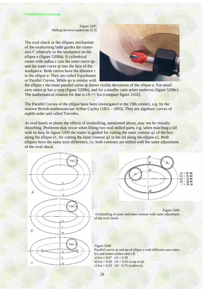
Figure 5207 Milling the bowl underside [6.3]
The oval chuck or the ellipses mechanism of the ovalturning lathe guides the router-axis C relatively to the workpiece on the ellipse e (figure 5208a). A cylindrical router with radius r cuts the outer curve qo and the inner curve qi into the face of the workpiece. Both curves have the distance r to the ellipse e. They are called Equidistant or Parallel Curves. While qo is similar with the ellipse e the inner parallel curve qi shows visible deviations of the ellipse e. For small axes ratios qi has a cusp (figure 5208b), and for a smaller ratio arises undercut (figure 5208c). The mathematical relation for that is r/b => b/a (compare figure 2102). The Parallel Curves of the ellipse have been investigated in the 19th century, e.g. by the renown British mathematician Arthur Cayley (1821 - 1895). They are algebraic curves of eighth order and called Toroides. At oval bowls or plates the effects of ovalmilling, mentioned above, may not be visually disturbing. Problems may occur when fitting two oval milled parts, e.g. when matching a lid with its box. In figure 5209 the router is guided for cutting the outer contour q1 of the box along the ellipse e1, for cutting the inner contour q2 in the lid along the ellipse e2. Both ellipses have the same axes difference, i.e. both contours are milled with the same adjustment of the oval chuck
Figure 5209 Ovalmilling of outer and inner contour with same adjustment
of the oval chuck Figure 5208 Parallel curves qi und qo of ellipse e with different axes ratios b/a and router-radius-ratio r/b a) b/a = 0,67 r/b = 0,38 b) b/a = 0,50 r/b = 0,50 (cusp at qi) c) b/a = 0,33 r/b = 0,75 (undercut)
6 Methods of Ovalturning
30
6.5 Ovalturning of Facework (Cross Grain) Oval bowls, plates, platters, frames and many more of the oval objects mentioned in the list of oval turned items for use in general are turned as facework, i.e. of cross grain blanks. In ovalturning the flatter the object the more simple is the turning process. Ovalturning of deep objects, bowls or vases for instance, is more complicated. In the old literature there is no description of the way tool are used to produce the cleanest cuts and smoothest surfaces. Using scrapers, shavings can easily be made but producing a smooth surface on wooden pieces is not so easy. Spannagel, the author of the German woodturner bible „Das Drechslerwerk“, published in 1940 [1.1.2], wrote, in the chapter Ovalturning, that the only way to get acquainted with the practice of ovalturning, especially handling the tools, is to watch an efficient and competent master. Unfortunately such a master is not be found easily today. On the other hand, the masters hardly understood the geometric relations because any books of the time presented, at the most, a scant outline showing that the tool has to cut in spindle height. Scrapers have, historically, been used in preference to gouges. It is easier to lay scrapers on a plane tool rest enabling it to be kept at centre height.
6.6 Ovalturning of Frames
The first book that was dedicated exclusively to ovalturning of frames was the German "Handbuch der Ovaldreherei" (Manual of Ovalturning) [1.1.1]. It was written in 1920 by Hugo Knoppe, meritorious teacher at the Technical College for Turners, Carvers and Sculptors in Leipzig / Saxony. Oval frames were produced in large quantities in frame-making factories. The frame blanks were made up of 4 or 6 parts. Each factory had its own technique for joining the frame blank parts, predominant were mortise and tenon joints as seen preserved in the oval frame factory, The Old Schwamb Mill in the USA [6.2] [2.2.12]. In Germany there was a factory that offered horseshoe-like bent wood arcs. The arcs were glued together using a scarf joint. These frame blanks had the advantage that the fibres ran lengthways with the oval, and that assisted in yielding a good surface finish. The frame factories delivered frames of all sizes, all profiles and ornaments and all manners of surfaces, e.g. painted, gilded, with spun metal inlays and also natural. The skills shown in the production of these forms were excellent. Today those same skills are less easily found.
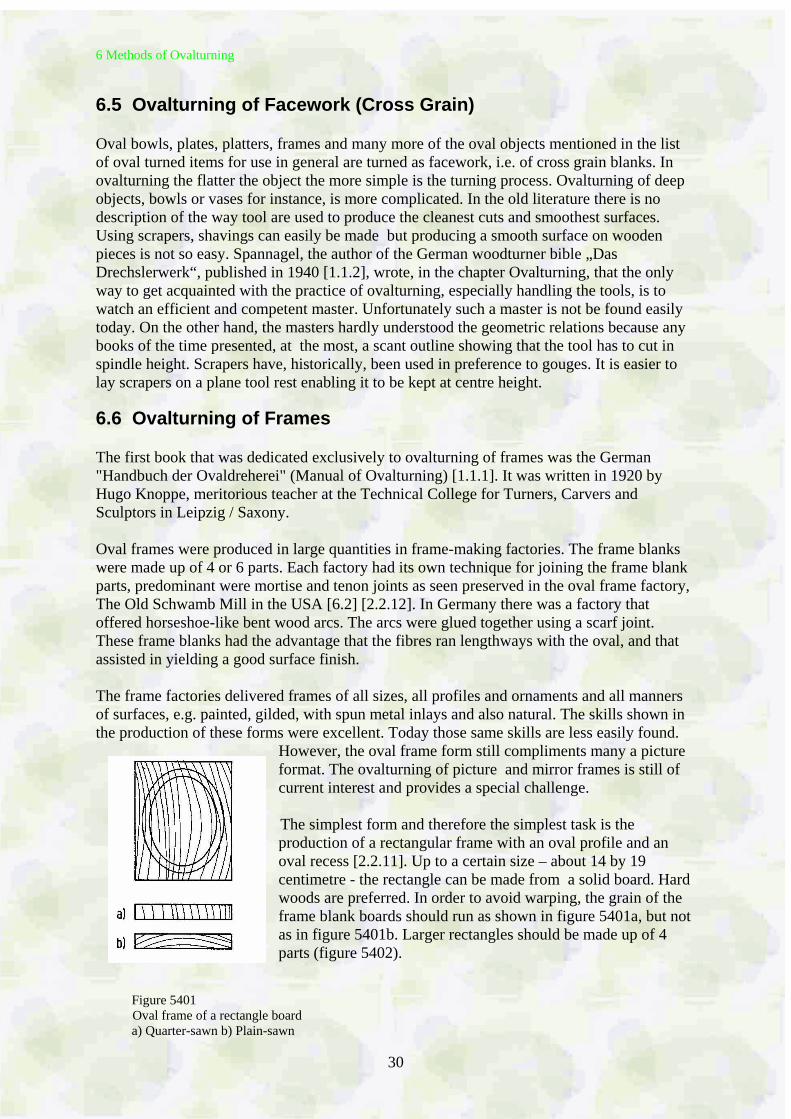
However, the oval frame form still compliments many a picture format. The ovalturning of picture and mirror frames is still of current interest and provides a special challenge. The simplest form and therefore the simplest task is the production of a rectangular frame with an oval profile and an oval recess [2.2.11]. Up to a certain size – about 14 by 19 centimetre - the rectangle can be made from a solid board. Hard woods are preferred. In order to avoid warping, the grain of the frame blank boards should run as shown in figure 5401a, but not as in figure 5401b. Larger rectangles should be made up of 4 parts (figure 5402).
Figure 5401
Oval frame of a rectangle board a) Quarter-sawn b) Plain-sawn
6 Methods of Ovalturning
31
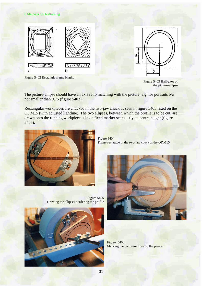
Figure 5402 Rectangle frame blanks Figure 5403 Half-axes of
the picture-ellipse
The picture-ellipse should have an axis ratio matching with the picture, e.g. for portraits b/a not smaller than 0,75 (figure 5403). Rectangular workpieces are chucked in the two-jaw chuck as seen in figure 5405 fixed on the ODM15 (with adjusted lightline). The two ellipses, between which the profile is to be cut, are drawn onto the running workpiece using a fixed marker set exactly at centre height (figure 5405).
Figure 5404 Frame rectangle in the two-jaw chuck at the ODM15
Figure 5405 Drawing the ellipses bordering the profile
Figure 5406 Marking the picture-ellipse by the piercer
6 Methods of Ovalturning
32
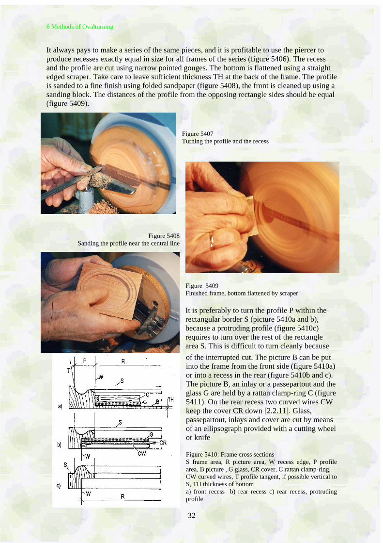
It always pays to make a series of the same pieces, and it is profitable to use the piercer to produce recesses exactly equal in size for all frames of the series (figure 5406). The recess and the profile are cut using narrow pointed gouges. The bottom is flattened using a straight edged scraper. Take care to leave sufficient thickness TH at the back of the frame. The profile is sanded to a fine finish using folded sandpaper (figure 5408), the front is cleaned up using a sanding block. The distances of the profile from the opposing rectangle sides should be equal (figure 5409).
Figure 5407 Turning the profile and the recess
Figure 5408 Sanding the profile near the central line
Figure 5409 Finished frame, bottom flattened by scraper It is preferably to turn the profile P within the rectangular border S (picture 5410a and b), because a protruding profile (figure 5410c) requires to turn over the rest of the rectangle area S. This is difficult to turn cleanly because
of the interrupted cut. The picture B can be put into the frame from the front side (figure 5410a) or into a recess in the rear (figure 5410b and c). The picture B, an inlay or a passepartout and the glass G are held by a rattan clamp-ring C (figure 5411). On the rear recess two curved wires CW keep the cover CR down [2.2.11]. Glass, passepartout, inlays and cover are cut by means of an ellipsograph provided with a cutting wheel or knife Figure 5410: Frame cross sections S frame area, R picture area, W recess edge, P profile area, B picture , G glass, CR cover, C rattan clamp-ring, CW curved wires, T profile tangent, if possible vertical to S, TH thickness of bottom a) front recess b) rear recess c) rear recess, protruding profile
6 Methods of Ovalturning
33
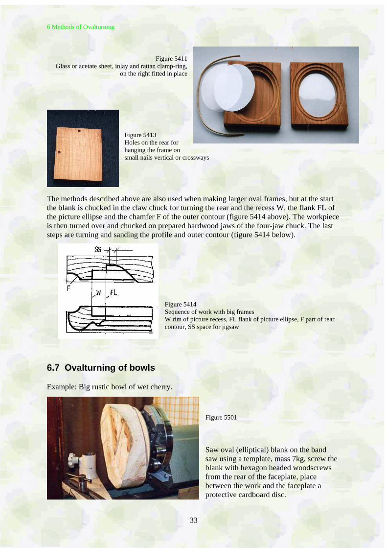
Figure 5411
Glass or acetate sheet, inlay and rattan clamp-ring, on the right fitted in place
Figure 5413 Holes on the rear for hanging the frame on small nails vertical or crossways
The methods described above are also used when making larger oval frames, but at the start the blank is chucked in the claw chuck for turning the rear and the recess W, the flank FL of the picture ellipse and the chamfer F of the outer contour (figure 5414 above). The workpiece is then turned over and chucked on prepared hardwood jaws of the four-jaw chuck. The last steps are turning and sanding the profile and outer contour (figure 5414 below).
Figure 5414 Sequence of work with big frames W rim of picture recess, FL flank of picture ellipse, F part of rear contour, SS space for jigsaw
6.7 Ovalturning of bowls Example: Big rustic bowl of wet cherry.
Figure 5501 Saw oval (elliptical) blank on the band saw using a template, mass 7kg, screw the blank with hexagon headed woodscrews from the rear of the faceplate, place between the work and the faceplate a protective cardboard disc.
6 Methods of Ovalturning
34
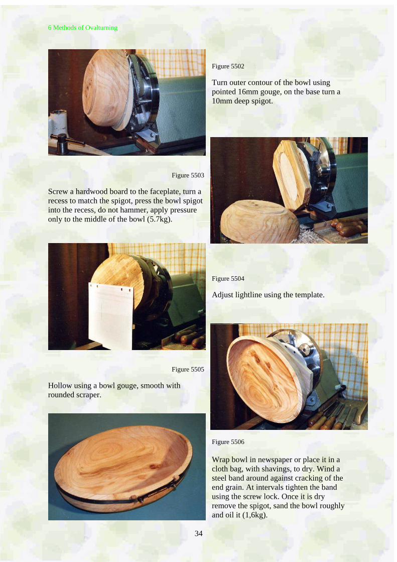
Figure 5502
Turn outer contour of the bowl using pointed 16mm gouge, on the base turn a 10mm deep spigot.
Figure 5503 Screw a hardwood board to the faceplate, turn a recess to match the spigot, press the bowl spigot into the recess, do not hammer, apply pressure only to the middle of the bowl (5.7kg).
Figure 5504 Adjust lightline using the template.
Figure 5505 Hollow using a bowl gouge, smooth with rounded scraper.
Figure 5506 Wrap bowl in newspaper or place it in a cloth bag, with shavings, to dry. Wind a steel band around against cracking of the end grain. At intervals tighten the band using the screw lock. Once it is dry remove the spigot, sand the bowl roughly and oil it (1,6kg).
6 Methods of Ovalturning
35
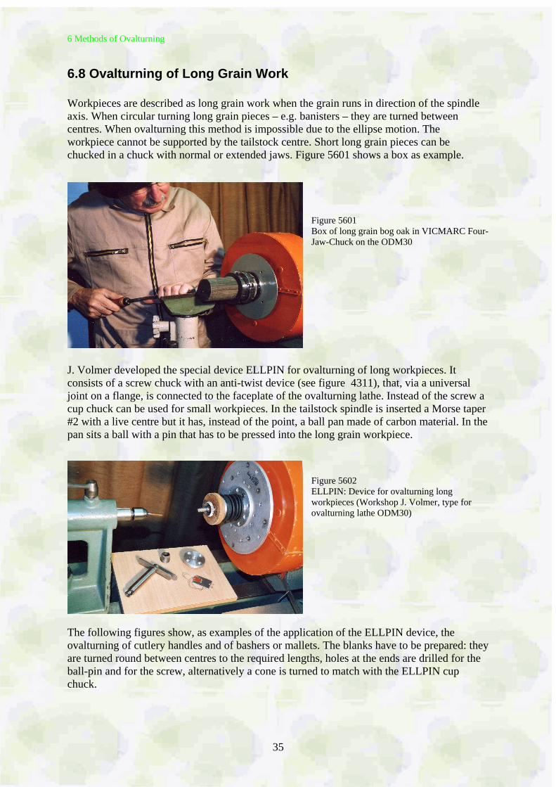
6.8 Ovalturning of Long Grain Work Workpieces are described as long grain work when the grain runs in direction of the spindle axis. When circular turning long grain pieces – e.g. banisters – they are turned between centres. When ovalturning this method is impossible due to the ellipse motion. The workpiece cannot be supported by the tailstock centre. Short long grain pieces can be chucked in a chuck with normal or extended jaws. Figure 5601 shows a box as example.
Figure 5601 Box of long grain bog oak in VICMARC Four-Jaw-Chuck on the ODM30
J. Volmer developed the special device ELLPIN for ovalturning of long workpieces. It consists of a screw chuck with an anti-twist device (see figure 4311), that, via a universal joint on a flange, is connected to the faceplate of the ovalturning lathe. Instead of the screw a cup chuck can be used for small workpieces. In the tailstock spindle is inserted a Morse taper #2 with a live centre but it has, instead of the point, a ball pan made of carbon material. In the pan sits a ball with a pin that has to be pressed into the long grain workpiece.
Figure 5602 ELLPIN: Device for ovalturning long workpieces (Workshop J. Volmer, type for ovalturning lathe ODM30)
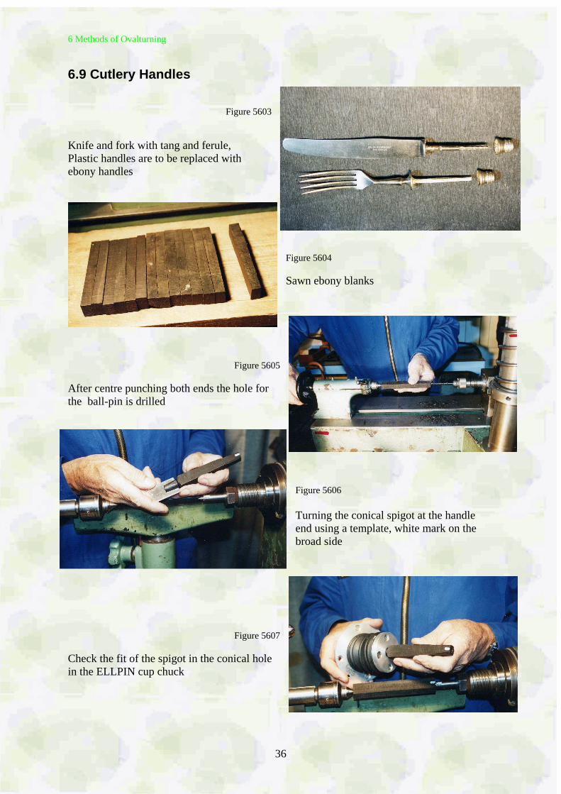
The following figures show, as examples of the application of the ELLPIN device, the ovalturning of cutlery handles and of bashers or mallets. The blanks have to be prepared: they are turned round between centres to the required lengths, holes at the ends are drilled for the ball-pin and for the screw, alternatively a cone is turned to match with the ELLPIN cup chuck.
6 Methods of Ovalturning
36
6.9 Cutlery Handles
Figure 5603
Knife and fork with tang and ferule, Plastic handles are to be replaced with ebony handles
Figure 5604 Sawn ebony blanks
Figure 5605
After centre punching both ends the hole for the ball-pin is drilled
Figure 5606 Turning the conical spigot at the handle end using a template, white mark on the broad side
Figure 5607
Check the fit of the spigot in the conical hole in the ELLPIN cup chuck
6 Methods of Ovalturning
37
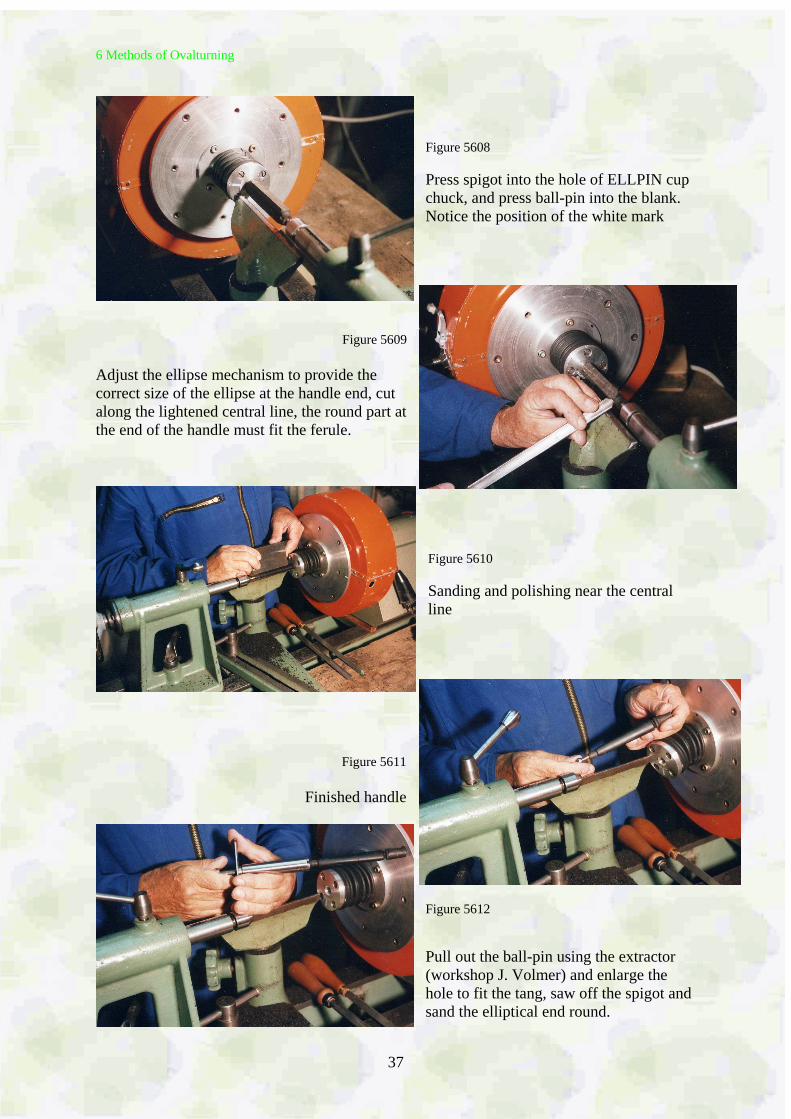
Figure 5608 Press spigot into the hole of ELLPIN cup chuck, and press ball-pin into the blank. Notice the position of the white mark
Figure 5609 Adjust the ellipse mechanism to provide the correct size of the ellipse at the handle end, cut along the lightened central line, the round part at the end of the handle must fit the ferule.
Figure 5610 Sanding and polishing near the central line
Figure 5611
Finished handle
Figure 5612 Pull out the ball-pin using the extractor (workshop J. Volmer) and enlarge the hole to fit the tang, saw off the spigot and sand the elliptical end round.
6 Methods of Ovalturning
38
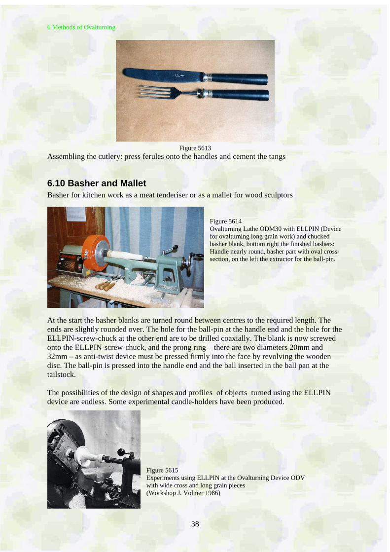
Figure 5613
Assembling the cutlery: press ferules onto the handles and cement the tangs
6.10 Basher and Mallet Basher for kitchen work as a meat tenderiser or as a mallet for wood sculptors
Figure 5614 Ovalturning Lathe ODM30 with ELLPIN (Device for ovalturning long grain work) and chucked basher blank, bottom right the finished bashers: Handle nearly round, basher part with oval cross- section, on the left the extractor for the ball-pin.
At the start the basher blanks are turned round between centres to the required length. The ends are slightly rounded over. The hole for the ball-pin at the handle end and the hole for the ELLPIN-screw-chuck at the other end are to be drilled coaxially. The blank is now screwed onto the ELLPIN-screw-chuck, and the prong ring – there are two diameters 20mm and 32mm – as anti-twist device must be pressed firmly into the face by revolving the wooden disc. The ball-pin is pressed into the handle end and the ball inserted in the ball pan at the tailstock. The possibilities of the design of shapes and profiles of objects turned using the ELLPIN device are endless. Some experimental candle-holders have been produced.
Figure 5615 Experiments using ELLPIN at the Ovalturning Device ODV with wide cross and long grain pieces (Workshop J. Volmer 1986)
7 Grinding and 8 Finishing
39
7 Sanding
When sanding oval turned work the same methods and materials are used as when sanding circular turned pieces on the lathe. It has to be taken into account that when sanding the workpiece on a running ovalturning lathe abrasive paper and rotating sanding pads can only be held on the area of the central line, though. The sanding systems offered for circular turning have been successfully tried and tested for ovalturning, and they work well. But remember: What is not cut cleanly cannot be sanded cleanly.
8 Finishing
There are no special methods for the surface treatment of oval turned pieces, except that apply he finish, e.g. varnish, on the running workpiece is only possible around the central line.
9 Ornamenting
40
9 Ornamenting
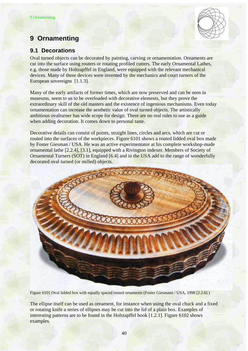
9.1 Decorations Oval turned objects can be decorated by painting, carving or ornamentation. Ornaments are cut into the surface using routers or rotating profiled cutters. The early Ornamental Lathes, e.g. those made by Holtzapffel in England, were equipped with the relevant mechanical devices. Many of these devices were invented by the mechanics and court turners of the European sovereigns [1.1.3]. Many of the early artifacts of former times, which are now preserved and can be seen in museums, seem to us to be overloaded with decorative elements, but they prove the extraordinary skill of the old masters and the existence of ingenious mechanisms. Even today ornamentation can increase the aesthetic value of oval turned objects. The artistically ambitious ovalturner has wide scope for design. There are no real rules to use as a guide when adding decoration. It comes down to personal taste. Decorative details can consist of points, straight lines, circles and arcs, which are cut or routed into the surfaces of the workpieces. Figure 6101 shows a routed lidded oval box made by Foster Giesman / USA. He was an active experimentator at his complete workshop-made ornamental lathe [2.2.4], [3.1], equipped with a Rivington indexer. Members of Society of Ornamental Turners (SOT) in England [6.4] and in the USA add to the range of wonderfully decorated oval turned (or milled) objects.
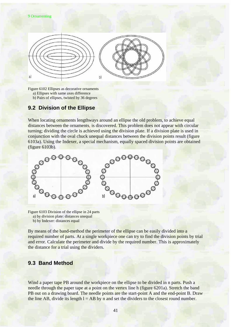
Figure 6101 Oval lidded box with equally spaced routed ornaments (Foster Giesmann / USA, 1998 [2.2.6] ) The ellipse itself can be used as ornament, for instance when using the oval chuck and a fixed or rotating knife a series of ellipses may be cut into the lid of a plain box. Examples of interesting patterns are to be found in the Holtzapffel book [1.2.1]. Figure 6102 shows examples.
9 Ornamenting
41
Figure 6102 Ellipses as decorative ornaments a) Ellipses with same axes difference b) Pairs of ellipses, twisted by 36 degrees
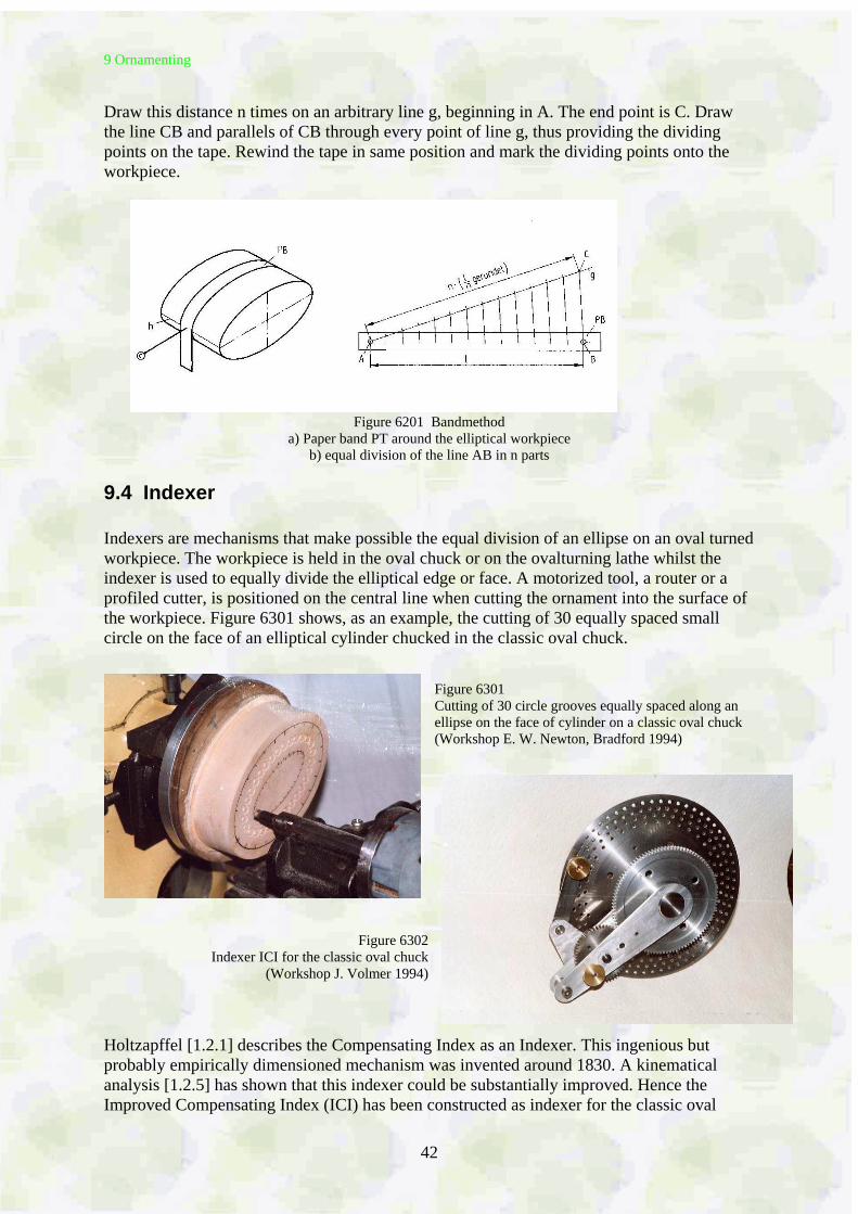
9.2 Division of the Ellipse When locating ornaments lengthways around an ellipse the old problem, to achieve equal distances between the ornaments, is discovered. This problem does not appear with circular turning; dividing the circle is achieved using the division plate. If a division plate is used in conjunction with the oval chuck unequal distances between the division points result (figure 6103a). Using the Indexer, a special mechanism, equally spaced division points are obtained (figure 6103b).
Figure 6103 Division of the ellipse in 24 parts a) by division plate: distances unequal b) by Indexer: distances equal By means of the band-method the perimeter of the ellipse can be easily divided into a required number of parts. At a single workpiece one can try to find the division points by trial and error. Calculate the perimeter and divide by the required number. This is approximately the distance for a trial using the dividers.
9.3 Band Method Wind a paper tape PB around the workpiece on the ellipse to be divided in n parts. Push a needle through the paper tape at a point on the vertex line h (figure 6201a). Stretch the band PB out on a drawing board. The needle points are the start-point A and the end-point B. Draw the line AB, divide its length l = AB by n and set the dividers to the closest round number.
9 Ornamenting
42
Draw this distance n times on an arbitrary line g, beginning in A. The end point is C. Draw the line CB and parallels of CB through every point of line g, thus providing the dividing points on the tape. Rewind the tape in same position and mark the dividing points onto the workpiece.
Figure 6201 Bandmethod a) Paper band PT around the elliptical workpiece
b) equal division of the line AB in n parts
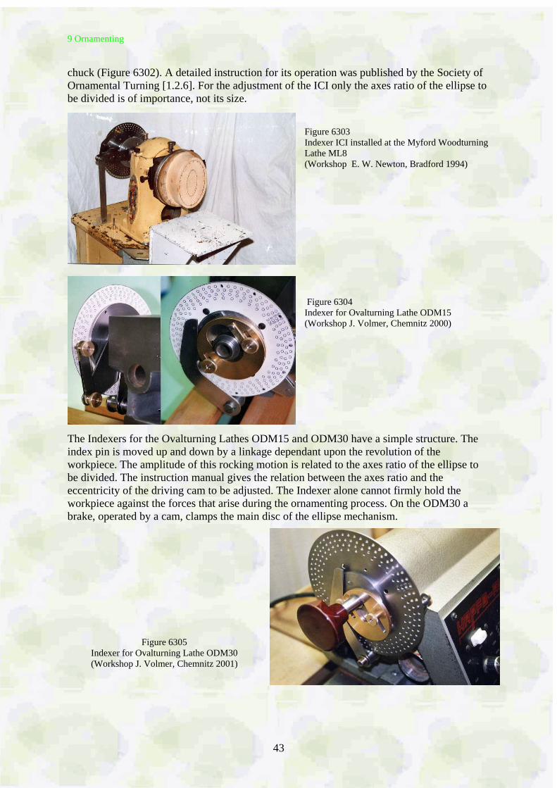
9.4 Indexer Indexers are mechanisms that make possible the equal division of an ellipse on an oval turned workpiece. The workpiece is held in the oval chuck or on the ovalturning lathe whilst the indexer is used to equally divide the elliptical edge or face. A motorized tool, a router or a profiled cutter, is positioned on the central line when cutting the ornament into the surface of the workpiece. Figure 6301 shows, as an example, the cutting of 30 equally spaced small circle on the face of an elliptical cylinder chucked in the classic oval chuck.
Figure 6301 Cutting of 30 circle grooves equally spaced along an ellipse on the face of cylinder on a classic oval chuck (Workshop E. W. Newton, Bradford 1994)
Figure 6302 Indexer ICI for the classic oval chuck
(Workshop J. Volmer 1994)
Holtzapffel [1.2.1] describes the Compensating Index as an Indexer. This ingenious but probably empirically dimensioned mechanism was invented around 1830. A kinematical analysis [1.2.5] has shown that this indexer could be substantially improved. Hence the Improved Compensating Index (ICI) has been constructed as indexer for the classic oval
9 Ornamenting
43
chuck (Figure 6302). A detailed instruction for its operation was published by the Society of Ornamental Turning [1.2.6]. For the adjustment of the ICI only the axes ratio of the ellipse to be divided is of importance, not its size.
Figure 6303 Indexer ICI installed at the Myford Woodturning Lathe ML8 (Workshop E. W. Newton, Bradford 1994) Figure 6304 Indexer for Ovalturning Lathe ODM15 (Workshop J. Volmer, Chemnitz 2000)
The Indexers for the Ovalturning Lathes ODM15 and ODM30 have a simple structure. The index pin is moved up and down by a linkage dependant upon the revolution of the workpiece. The amplitude of this rocking motion is related to the axes ratio of the ellipse to be divided. The instruction manual gives the relation between the axes ratio and the eccentricity of the driving cam to be adjusted. The Indexer alone cannot firmly hold the workpiece against the forces that arise during the ornamenting process. On the ODM30 a brake, operated by a cam, clamps the main disc of the ellipse mechanism.
Figure 6305
Indexer for Ovalturning Lathe ODM30 (Workshop J. Volmer, Chemnitz 2001)
9 Ornamenting
44
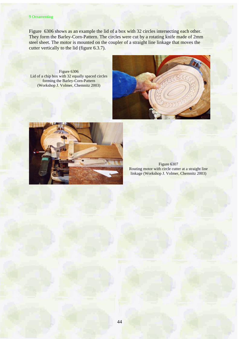
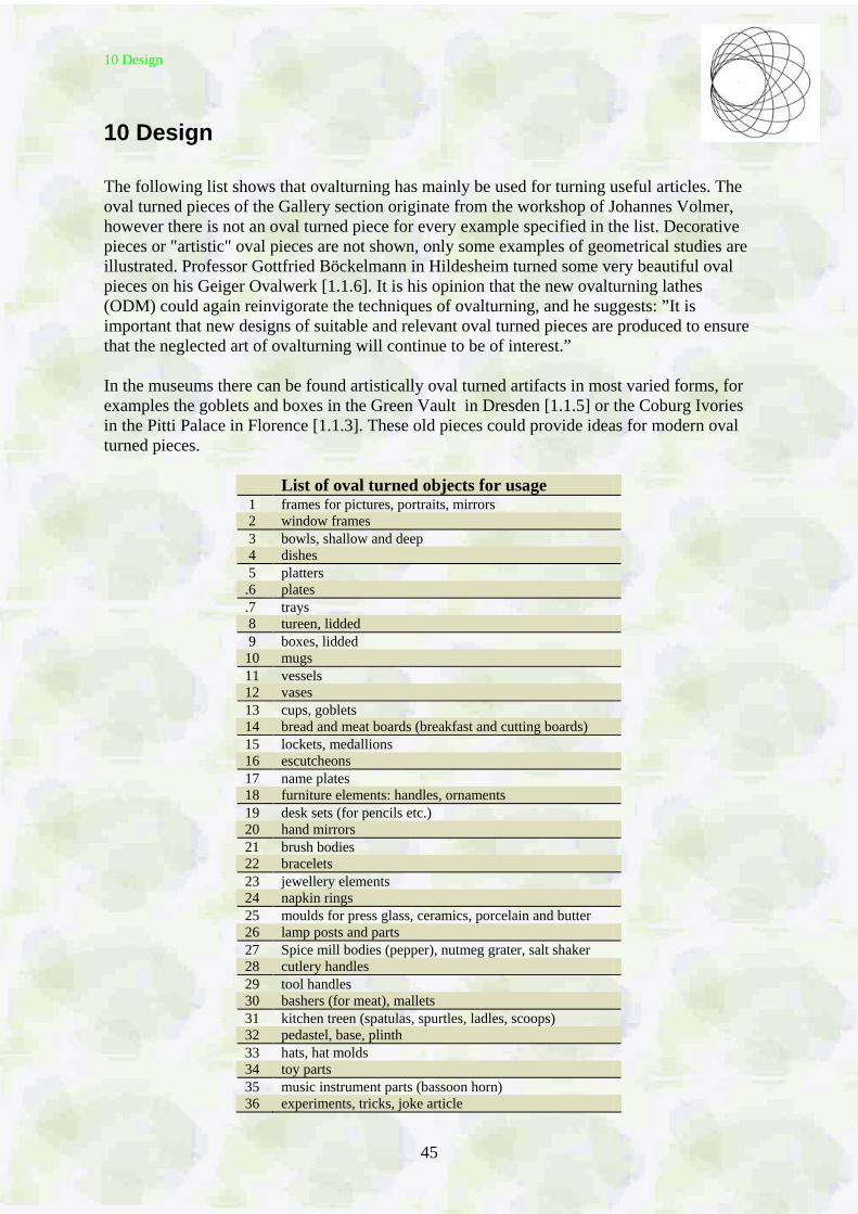
Figure 6306 shows as an example the lid of a box with 32 circles intersecting each other. They form the Barley-Corn-Pattern. The circles were cut by a rotating knife made of 2mm steel sheet. The motor is mounted on the coupler of a straight line linkage that moves the cutter vertically to the lid (figure 6.3.7).
Figure 6306
Lid of a chip box with 32 equally spaced circles forming the Barley-Corn-Pattern
(Workshop J. Volmer, Chemnitz 2003)
Figure 6307 Routing motor with circle cutter at a straight line linkage (Workshop J. Volmer, Chemnitz 2003)
10 Design
45
10 Design
The following list shows that ovalturning has mainly be used for turning useful articles. The oval turned pieces of the Gallery section originate from the workshop of Johannes Volmer, however there is not an oval turned piece for every example specified in the list. Decorative pieces or "artistic" oval pieces are not shown, only some examples of geometrical studies are illustrated. Professor Gottfried Böckelmann in Hildesheim turned some very beautiful oval pieces on his Geiger Ovalwerk [1.1.6]. It is his opinion that the new ovalturning lathes (ODM) could again reinvigorate the techniques of ovalturning, and he suggests: ”It is important that new designs of suitable and relevant oval turned pieces are produced to ensure that the neglected art of ovalturning will continue to be of interest.” In the museums there can be found artistically oval turned artifacts in most varied forms, for examples the goblets and boxes in the Green Vault in Dresden [1.1.5] or the Coburg Ivories in the Pitti Palace in Florence [1.1.3]. These old pieces could provide ideas for modern oval turned pieces.
List of oval turned objects for usage 1 frames for pictures, portraits, mirrors 2 window frames 3 bowls, shallow and deep 4 dishes 5 platters .6 plates .7 trays 8 tureen, lidded 9 boxes, lidded 10 mugs 11 vessels 12 vases 13 cups, goblets 14 bread and meat boards (breakfast and cutting boards) 15 lockets, medallions 16 escutcheons 17 name plates 18 furniture elements: handles, ornaments 19 desk sets (for pencils etc.) 20 hand mirrors 21 brush bodies 22 bracelets 23 jewellery elements 24 napkin rings 25 moulds for press glass, ceramics, porcelain and butter 26 lamp posts and parts 27 Spice mill bodies (pepper), nutmeg grater, salt shaker 28 cutlery handles 29 tool handles 30 bashers (for meat), mallets 31 kitchen treen (spatulas, spurtles, ladles, scoops) 32 pedastel, base, plinth 33 hats, hat molds 34 toy parts 35 music instrument parts (bassoon horn) 36 experiments, tricks, joke article
10 Design
46
When drafting oval pieces the designer has one dimension more at his disposal than when designing round objects. So far this advantage has only been used in a classical way. It is suggested that modern forms are explored and past forms are re-examined. At the beginning - also with experiments - a design drawing will stand. Using the computer, as a tool, will allow the more complicated geometrical/mathematical problems to be solved and at the same time produce good working drawings. Part of the woodturner´s apprenticeship is the understanding and production of technical working drawings [1.1.2] [1.1.4]. Today computer programs for drawings are available. One can thereby produce, as soon as one knows or has sketched the intended cross section, arbitrary views of the complete intended piece and also provide an impression of its spatial effect. Rotating a round body, i.e. a rotational symmetric body, around its axis the same figure is always to be seen. It is not the same with oval pieces. The following perspective drawings of the views of an oval bowl in net representation show the very different, partly unexpected figures. Consider e.g. the forms and mutual positions of the two ellipses at the bottom and at the rim of the bowl.
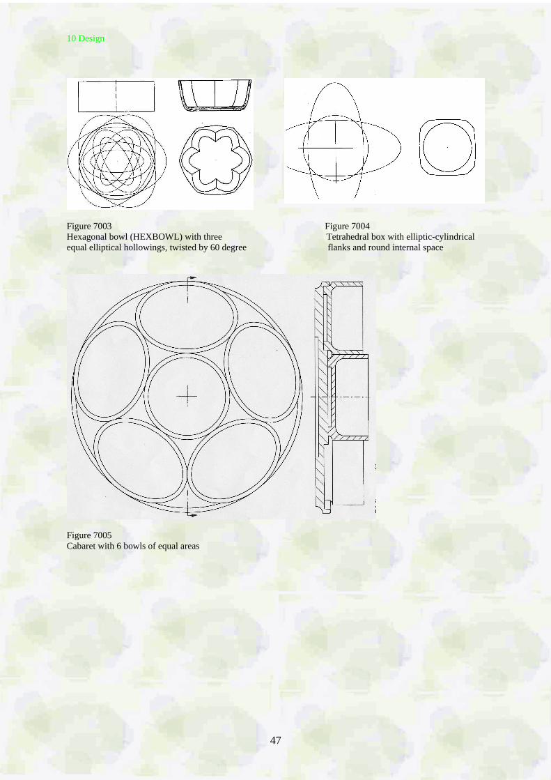
Figure 7001 Side views and top view of a bowl with elliptical contour line and parabolic cross section line
Figure 7002
Perspective views of the bowl of figure 7001 in positions when rotating around its vertical z-axis
When circular turning, interesting forms can be obtained by turning the piece around different axes. A number of books show examples but not all look good. With ovalturning form variants can be achieved only by rotating the workpiece around its central axis. The following figures show those designs, a hexagonal bowl with elliptical hollowings (figure 7003) and a four-edged box with elliptical-cylindrical flanks and circular hollowing (figure 7004). With the cabaret (Figure 7005) the problem presented is to ensure that the five oval bowls and the round bowl in the centre all have the same area.
10 Design
47
Figure 7003 Figure 7004 Hexagonal bowl (HEXBOWL) with three Tetrahedral box with elliptic-cylindrical equal elliptical hollowings, twisted by 60 degree flanks and round internal space
Figure 7005 Cabaret with 6 bowls of equal areas
11 Gallery
48
11 Gallery See the homepage for a better view of the figures shown here below in the gallery: www.Volmer---Ovaldrehen.de.
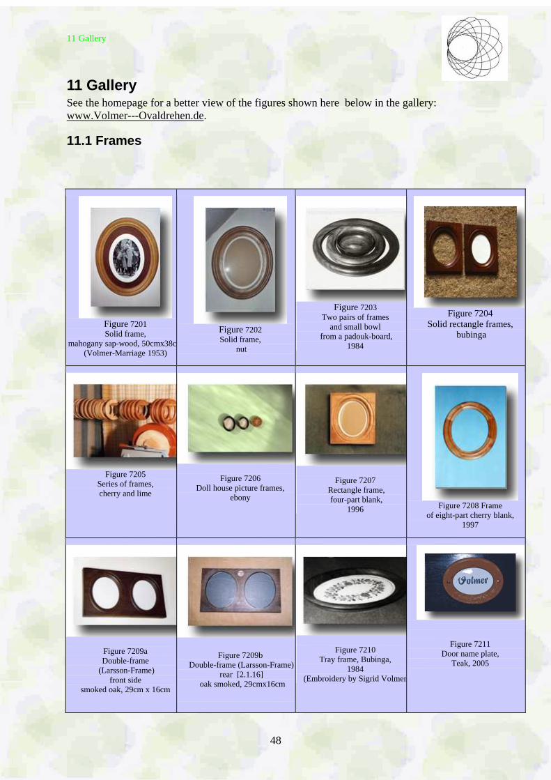
11.1 Frames
Figure 7201 Solid frame,
mahogany sap-wood, 50cmx38cm(Volmer-Marriage 1953)
Figure 7202 Solid frame,
nut
Figure 7203 Two pairs of frames
and small bowl from a padouk-board,
1984
Figure 7204 Solid rectangle frames,
bubinga
Figure 7205 Series of frames, cherry and lime
Figure 7206
Doll house picture frames, ebony
Figure 7207
Rectangle frame, four-part blank,
1996
Figure 7208 Frame of eight-part cherry blank,
1997
Figure 7209a Double-frame
(Larsson-Frame) front side
smoked oak, 29cm x 16cm
Figure 7209b Double-frame (Larsson-Frame)
rear [2.1.16] oak smoked, 29cmx16cm
Figure 7210
Tray frame, Bubinga, 1984
(Embroidery by Sigrid Volmer)
Figure 7211 Door name plate,
Teak, 2005
11 Gallery
49
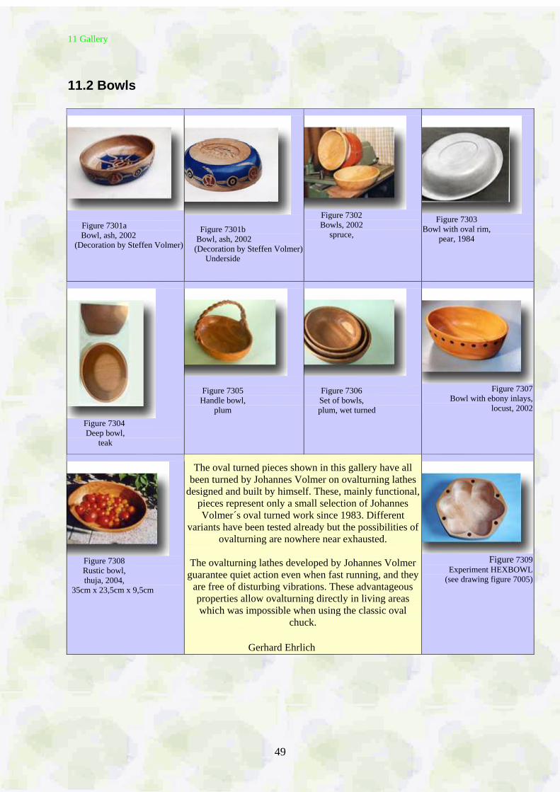
11.2 Bowls
Figure 7301a Bowl, ash, 2002 (Decoration by Steffen Volmer)
Figure 7301b Bowl, ash, 2002 (Decoration by Steffen Volmer)
Underside
Figure 7302 Bowls, 2002
spruce,
Figure 7303
Bowl with oval rim, pear, 1984
Figure 7304 Deep bowl,
teak
Figure 7305 Handle bowl,
plum
Figure 7306 Set of bowls,
plum, wet turned
Figure 7307
Bowl with ebony inlays, locust, 2002
Figure 7308 Rustic bowl, thuja, 2004,
35cm x 23,5cm x 9,5cm
The oval turned pieces shown in this gallery have all been turned by Johannes Volmer on ovalturning lathes
designed and built by himself. These, mainly functional, pieces represent only a small selection of Johannes Volmer´s oval turned work since 1983. Different
variants have been tested already but the possibilities of ovalturning are nowhere near exhausted.
The ovalturning lathes developed by Johannes Volmer guarantee quiet action even when fast running, and they
are free of disturbing vibrations. These advantageous properties allow ovalturning directly in living areas which was impossible when using the classic oval
chuck.
Gerhard Ehrlich
Figure 7309
Experiment HEXBOWL (see drawing figure 7005)
11 Gallery
50
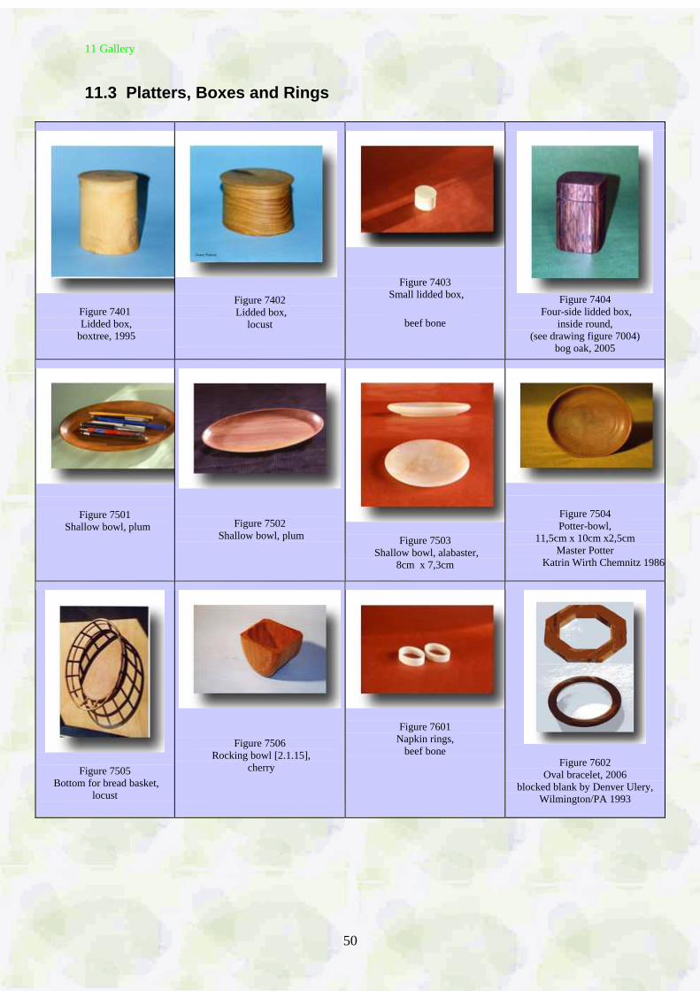
11.3 Platters, Boxes and Rings
Figure 7401 Lidded box,
boxtree, 1995
Figure 7402 Lidded box,
locust
Figure 7403 Small lidded box,
beef bone
Figure 7404
Four-side lidded box, inside round,
(see drawing figure 7004) bog oak, 2005
Figure 7501 Shallow bowl, plum
Figure 7502 Shallow bowl, plum
Figure 7503
Shallow bowl, alabaster, 8cm x 7,3cm
Figure 7504 Potter-bowl,
11,5cm x 10cm x2,5cm Master Potter
Katrin Wirth Chemnitz 1986
Figure 7505 Bottom for bread basket,
locust
Figure 7506 Rocking bowl [2.1.15],
cherry
Figure 7601
Napkin rings, beef bone
Figure 7602 Oval bracelet, 2006
blocked blank by Denver Ulery, Wilmington/PA 1993
11 Gallery
51
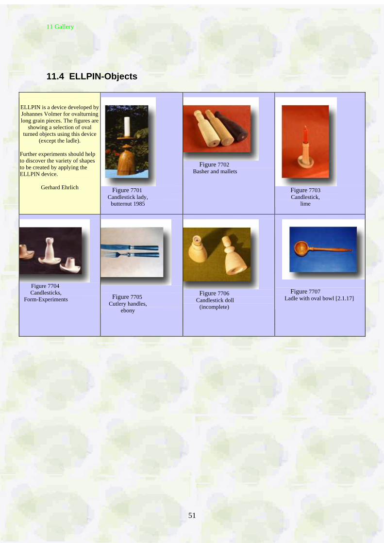
11.4 ELLPIN-Objects
ELLPIN is a device developed by Johannes Volmer for ovalturning long grain pieces. The figures are
showing a selection of oval turned objects using this device
(except the ladle).
Further experiments should help to discover the variety of shapes to be created by applying the ELLPIN device.
Gerhard Ehrlich Figure 7701
Candlestick lady, butternut 1985
Figure 7702
Basher and mallets
Figure 7703 Candlestick,
lime
Figure 7704
Candlesticks, Form-Experiments
Figure 7705 Cutlery handles,
ebony
Figure 7706
Candlestick doll (incomplete)
Figure 7707 Ladle with oval bowl [2.1.17]
11 Gallery
52
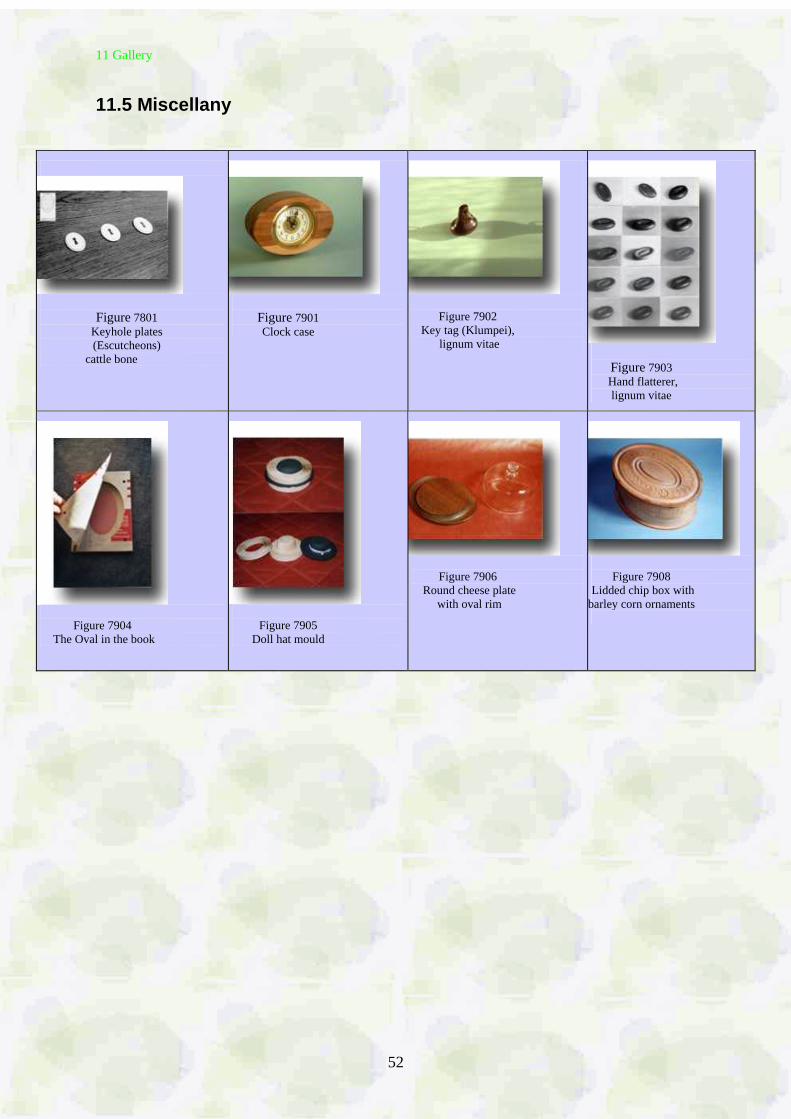
11.5 Miscellany
Figure 7801 Keyhole plates (Escutcheons)
cattle bone
Figure 7901 Clock case
Figure 7902 Key tag (Klumpei),
lignum vitae
Figure 7903 Hand flatterer, lignum vitae
Figure 7904 The Oval in the book
Figure 7905 Doll hat mould
Figure 7906 Round cheese plate
with oval rim
Figure 7908 Lidded chip box with barley corn ornaments
12 Literature
53
12 Literature (updated 30. July 2006) 1. Books 1.1. in German [1.1.1] Knoppe, H.: Handbuch der Ovaldreherei. Leipzig: Verlag der Deutschen Drechsler-Zeitung. Ernst Steiger 1920. Reprint: Hannover: Verlag Th. Schäfer 1986. [1.1.2] Spannagel, F.: Das Drechslerwerk. Ravensburg: Otto Maier Verlag 1940. Das Ovaldrehen S. 130 - 135. Reprint: Hannover: Verlag Th. Schäfer 1986 [1.1.3] Maurice, K. : Der drechselnde Souverän. Zürich: Ineichen Verlag 1985 [1.1.4] Steinert, R.: Drechseln in Holz. Leipzig: Fachbuchverlag 1990. Ovaldrechseln S. 174 - 178. [1.1.5] Syndram, D. u.a. : Wiedergewonnen - Elfenbeinkunststücke aus Dresden. Erbach: Deutsches Elfenbein Museum 1995 [1.1.6] Böckelmann, G.: Handbuch Drechseln. Ravensburg: Ravensburger Buchverlag 1997. Die Kunstdrechslerei: Das Ovaldrehen S. 142 1.2 in English [1.2.1] Holtzapffel, J. J.: Turning and Mechanical Manipulation, Volume 5. London: Holtzapffel & Co. 1884. Reprint: Holtzapffel, J.J.: The Principles and Practice of Ornamental or Complex Turning. New York: Dover Publication Incorporation 1973 [1.2.2] Evans, J.H.: Ornamental Turning. London: Evans 1886. Reprint: Mendham, New Jersey: The Astragal Press 1993. [1.2.3] Walshaw, T. D.: Ornamental Turning. Hemel Hempsted/England: Argus Books 1990, paperback 1994 The Elliptical Turning Chuck (Holtzapffel type): pages 128 - 135 [1.2.4] Springett, D.: Adventures in Woodturning. Lewes: Guild of Master Craftsman Publications Ltd. 1994. Part 3: Elliptical Turning, chapters: Oval Chuck, Oval Frame, Oval Frame with Moulded Edge, Oval Dish and Oval Box.48 pages [1.2.5] Newton, E. W. and Volmer, J. W.: The Equal Division of the Ellipse. London: Society of Ornamental Turners 1995 [1.2.6] Newton, E. W. , and Volmer, J. W.: The Improved Compensating Index (ICI). London: Society of Ornamental Turners 1995 [1.2.7] Ferguson, J., and Newton, E. W.: Towards a History of the Invention of the Elliptical Chuck. London: Society of Ornamental Turners 1996
12 Literature
54
[1.2.8] Newton, E. W.: Ellipses and Ovals - Their difference and construction. Elliptical Turning Association Bradford 1997, London: Library of the Society of Ornamental Turning 1997. [1.2.9] Darlow, Mike: Woodturning Methods. Chapter 7: Elliptical Turning. Exeter/ NSW Australia: The Melaleuca Press 1999 2. Essays 2.1. in German by J. Volmer [2.1.1] Ovaldrehen aus neuer Sicht. Holztechnologie, Leipzig 26 (1985) 1, S. 23 - 26. [2.1.2] Führungsgetriebe zur Herstellung elliptischer Werkstücke. Maschinenbautechnik, Berlin 34(1985) 8, S. 345 - 347. [2.1.3] Mechanismen für die Erzeugung ebener und räumlicher elliptischer Profillinien. Proceedings of the Seventh World Congress on the Theory of Machines and Mechanisms Sevilla September 1987, Volume 1, S. 211 - 214. Oxford: Pergamon Press 1987 [2.1.4] Ovaldrehen heute. Drechseln – Deutsche Drechsler-Zeitung (1993) 1, S. 10 - 12. [2.1.5] Mechanismen für die gleichmässige Teilung der Ellipse. Mechanism and Machine Theory 30 (1995) 8, S. 1255 - 1268. [2.1.6] Den Dreh raus: Eine neue Maschine für eine alte Handwerkskunst - das Ovaldrehen. Industriebedarf (1998) 4, S. 100 - 101. [2.1.7] Ein Mekka für Ovaldrechsler (Die Old Schwamb Mill). Drechseln - Deutsche Drechsler Zeitung (1998) 2, S. 12 - 13. In English in Internet http://www.oldschwambmill.org: A Mecca for Ovalturners, also in More Woodturning Vol 10 Nr. 8 (Sept./Oct 2005) p. 28/29 [2.1.8] Nicht zu erschüttern (Eine neue Maschine für eine alte Drechselkunst - das Ovaldrehen). Drechseln – Deutsche Drechsler-Zeitung (1998) 2, S.14 - 15. In English in Internet http://www.oldschwambmill.org/: [2.1.9] Eine neue Maschine für eine alte Drechselkunst - das Ovaldrehen. Drechseln - Deutsche Drechsler-Zeitung (2000) 2, S. 16. [2.1.10] Ovaldrehen für Anfänger. Drechseln – Deutsche Drechsler-Zeitung (2002) 2, S.17 - 19. [2.1.11] Ovaldrehen einfacher Stücke (Werkstückspannen mit Backenfutter). Drechseln - Deutsche Drechsler-Zeitung (2002) 4, S. 12 und 13. [2.1.12] Ovaldrehen - eine wiederbelebte Drechselkunst. Lignum (2003) 2, S.72 - 77.
12 Literature
55
[2.1.13] Oval im Buch. Leserzuschrift, teilweise in Drechseln - Deutsche Drechsler-Zeitung (2003) 1, S. 3. [2.1.14] Ovaldrehen kleiner Bilderrahmen. Drechseln – Deutsche Drechsler-Zeitung (2003) 4, S. 4 - 9. [2.1.15] Ovaldrehen einer Schaukelschale. Drechseln – Deutsche Drechsler-Zeitung (2005) 2, S. 6 - 8. [2.1.16] Ovaldrehen eines Doppelrahmens. Drechseln – Deutsche Drechsler-Zeitung (2006) 1, S. 6 – 7 [2.1.17] Ovaldrehen einer Schöpfkelle. Drechseln – Deutsche Drechsler-Zeitung 2.2 in English [2.2.1] Young, W. T.: The Old Schwamb Mill. Fine Woodworking (1986) 58, p. 74 - 78. See also internet www.oldschwambmill.org/ [2.2.2.] Volmer, J.: The Oval Lathe. Part 1: History of Ovalturning. American Woodturner, Vol. 4, Number 4, p. 29 (June 1990). Part 2: The Oval Lathe Mechanism. Vol. 5, Number 1, p. 26/27 (September 1990). Part 3: Oval Turning Techniques. Vol. 5, Number 2, p. 26 - 28 (December 1990). [2.2.3] Volmer, J.: Turning a deep oval bowl. Woodturning (1991) 5, p. 64 - 68 [2.2.4] Giesmann, Foster: Ornamental Oval Turning. American Woodturner Vol 9 (1994), Number 3 (September), p. 21 - 24 [2.2.5] Newton, E. W. , and Volmer, J. W.: Another Note on Ovals and Oval Generators. Bulletin of the Society of Ornamental Turners Vol. 20 (1997) Number 98, p. 125-130 [2.2.6] Newton, E. W. , and Volmer, J. W.: Learning Curves (Ovalturning - State of the Art & Perspectives). Woodturning (1999) 71, p. 76 - 80 [2.2.7] Volmer, J.: A New Machine for an old Woodturning Art - Ovalturning. More Woodturning Vol. 5, Number 3 (March 2000) pages 1 and 6. [2.2.8] Volmer, J.: The new VICMARC OVALTURNING DEVICE (Letter). More Woodturning Vol. 5, Number 5 (May 2000) page 9. [2.2.9] Volmer, J.: First World-Wide Ovalturning Courses Held. More Woodturning. Vol. 6, Number 3 (March 2001) pages 1 - 5. [2.2.10] Stephano, P. J.: Oval frames of world renown. Wood Magazine June 2001, pp. 68 - 71.
12 Literature
56
[2.2.11] Volmer, J.: Ovalturning Small Picture Frames. More Woodturning Vol. 7(2002), part 1: Number 4 (May 2002) pages 6 - 10, part 2: Number 5 (June 2002) page 4, complement Number 6 (July 2002) page 12 [2.2.12] Lacer, Alan: Oval Traditions - A visit to the oldest continously operating mill in North America (The Old Schwamb Mill). American Woodturner, Summer 2004, p. 24 - 27 [2.2.13] Volmer, J.: Oval Key-Container – an Australia-Saxony-Opus. More Woodturning Vol. 11 Number 2 (Feb. 2006), p. 29 [2.2.14] Volmer, J.: Workholding on the Ovalturning Lathe. More Woodturning Vol. 11, Number 5 (June 2005), p. 28 - 30 3. Videos [3.1] Giesmann, Foster: Oval Turning (Video). 519 W Taylor Street Space 401, Santa Maria, CA 93458 -1002, USA [3.2] Springett, D.: Elliptical Woodturning - An Introduction (Video). Lewes: Guild of Master Craftsman Publications Ltd. 1995 4. Magazines [4.1] Drechseln - Deutsche Drechsler-Zeitung. DruckVerlag Kettler GmbH, Postfach 1150, 59193 Boenen. Tel.:(023 83) 910130, Fax (023 83) 9101340. Editor Georg Panz: <[email protected]> [4.2] Woodturning. Guild of Master Craftsman Publication Ltd., 166 High Street, Lewes BN7 1XU, England. Fax 01273478606. Editor Colin Simpson et al.: <[email protected]>, Tel 01273477374 [4.3] The Woodturner. Nexus Special Interests Ltd., Nexus House, Atalea Drive, Swanley Kent BRH BHY, ENGLAND [4.4] More Woodturning. PO Box 2168, Snohomish, WA 98291, USA by Fred Holder <[email protected]> [4.5] Turning Points. Wood Turning Center, 501 Vine Street, Philadelphia, PA 19106. www.woodturningcenter.org
12 Literature
57
5. Ovalturning Lathe Producer , Ovalturning Schools and Users [5.1] VICMARC Machinery PTY. LTD., 52 Grice Street, Clontarf, Qld 4019, Australia. Tel +61 7 3284 3103, Fax +61 7 3283 4656. www.vicmarc.com German VICMARC Agent: Martin Weinbrecht, Drechselstube Neckarsteinach, Finkenweg 11, D-69239 Neckarsteinach. www.drechselstube.de [5.2] John Rea, 22A Fourth Avenue, Llandilo, NSW, Australia 2747 <[email protected]> [5.3] Dan Bollinger: (BOTULA Bollinger OvalTurning Lathe) <[email protected]> [5.4] Drechselzentrum Erzgebirge Steinert . Heuweg 3, D9526 Olbernhau. www. drechselzentrum.de, <[email protected]> [5.5] E. W. Newton 5 Beacon Brow, Horton Bank Top, Bradford BD6 3DE, ENGLAND <[email protected]> [5.6] Drechslerschule Schiers, Peter Luisoni (Woodturner School: Ovalturning courses using classic oval chucks) www.drechslerschule.ch [5.7] A. C. Smit, PoBox 32037, Glenstantia 0010, Pretoria, Republic of South Africa 6. Internet-Addresses - [6.1] Elliptical Turning Association (ETA): www.elliptical-turning-association.co.uk [6.2] Old Schwamb Mill www.oldschwambmill.org [6.3] Bollinger Ovalturning Lathe (BOTULA) www.claycritters.com/lathe/index.htm [6.4] The Society of Ornamental Turning, London www.the-sot.com [6.5] Technische Universität Chemnitz
www.tu-chemnitz.de/ Fakultät Maschinenbau/ Mechatronische Antriebstechnik/Getriebebibliothek (Mechanism Library)
[6.6] WEMA Werkzeug- und Maschinenbau, Gerbergasse 5, D-09526 Olbernhau
www.wema-olbernhau.com
13 Author
58
13 Author Johannes Volmer (pronounced Follmer), born 1930, grew up in Dresden, the Kings' residence of Saxony, famous for its baroque architecture, art galleries, china and museums. Following the town's terrible destruction at the end of the war, living conditions forced him, as a pupil and student, to work in several shops. The practical experience he gained of many kinds of handicraft and the machining of woods and metals led to his becoming a machine designer at Chemnitz, an industrial centre of machinery in Germany. Johannes graduated from the Technical University of Dresden where he also gained higher degrees. His specialities are mechanics and design of mechanisms. He has taught these subjects for 36 years as full Professor at the Technical University of Chemnitz. The country nearby, the forested Ore Mountains (Erzgebirge), is Germany's oldest woodworking region with ancient traditions and unique turning techniques still in use today. Woodturning is widely practised there. It was these circumstances that decided Johannes, some 25 years ago, to devote himself to the theory and practice of the almost forgotten art of ovalturning. His studies resulted in his designing novel ellipse mechanisms for ovalturning lathes which he tested himself. Johannes demonstrated ovalturning, i.e. the turning of elliptical pieces, at home in Germany at woodturning symposia and in countries abroad, e.g. England, the USA, France and Denmark. With E. W. Newton, his long-standing English ovalturning friend, he has founded the Elliptical Turning Association. It was intended as source of information in the internet and as a rendezvous of all fellows interested in ovalturning throughout the world (www.elliptical-turning association.co.uk). A number of publications on ovalturning has arisen in German and English magazines. Johannes Volmer is convinced that once turners have been introduced to ovalturning they will be keen to add it to their repertoire. This script Ovalturning and the ovalturning lathes that are expected on the market will hopefully promote this process. Contact: Johannes Volmer Salzstrasse 94 D 09113 Chemnitz GERMANY Tel / Fax +49 371 3304451 <[email protected]> http://www.Volmer---Ovaldrehen.de
14 Acknowledgement
59
14 Acknowledgement The author is very much obliged to Mr Gerhard Ehrlich for his editing the homepage and the script Ovalturning. Using his specialized knowledge at the computer and his great appreciation of the complicated topic of Ovalturning it was possible to transform the text drafts and picture documents of the author into the attractive form on hand. Without his patient and extensive work the project would not have taken place. For craftsmen interested in Ovaltuning it will be possible by reading this script to receive insight in the versatile and challenging lathe art of Ovalturning. Up to now there was not such a summary. Gerhard Ehrlich lives in Waldleite 17 D 09113 Chemnitz/Germany Tel +49 371 3361274 <[email protected]> The author wishes to thank David Springett for his generous help to improve the quality of the English version of the script Ovalturning. David found it to be an enjoyable and rewarding task to assist in improving the author´s English and to edit the text. David himself is well experienced in ovalturning. His excellent book “Adventures in Woodturning” [1.2.4] contains a chapter in which he describes his experiments with his shop-made oval chuck. This can be seen in his video [3.2]. This second edition of the script Ovalturning in English will hopefully help to promote the interest in ovalturning throughout the English speaking woodturning world. David Springett lives at 8, Strath Close Rugby Warwickshire CV21 England < [email protected]> Johannes Volmer Chemnitz, 1. August 2006