
Outline American College of Radiology CT …1 American College of Radiology CT Accreditation Program...
15
1 American College of Radiology CT Accreditation Program Doug Pfeiffer, MS, DABR Boulder Community Hospital Member of ACR CTAP Physics Subcommittee Outline CT Accreditation Program Overview Statistics Essentials • Personnel • Equipment • QA Technologist Level Testing Physicist Level Testing Site Scanning Instructions Image Quality Dose • CTDIw, CTDIvol, DLP, Effective Dose • Advanced Equipment Current CTAP Statistics Facilities active (current and under review): 881 Facilities currently accredited: 682 Units active: 1157 Units accredited: 850 0 200 400 600 800 1000 1200 Facilities Units Active Accredited Failure rate: 37% (6/1/2005 – 6/30/2006) Clinical only: 44% Phantom only: 37% Clinical + phantom: 19% Physician Requirements Radiologists Initial Board Certification, and 300 CT exams in past 36 months OR Completion of a diagnostic radiology residency, and 500 CT exams in past 36 months Continuing Experience 100 CT exams per year (recommended) Continuing Education 150 hours every three years (recommended)
Transcript of Outline American College of Radiology CT …1 American College of Radiology CT Accreditation Program...
1
American College of
Radiology
CT Accreditation Program
Doug Pfeiffer, MS, DABR
Boulder Community HospitalMember of ACR CTAP Physics Subcommittee
OutlineCT Accreditation Program Overview
Statistics
Essentials
• Personnel
• Equipment
• QA
Technologist Level Testing
Physicist Level Testing
Site Scanning InstructionsImage Quality
Dose• CTDIw, CTDIvol, DLP, Effective Dose
• Advanced Equipment
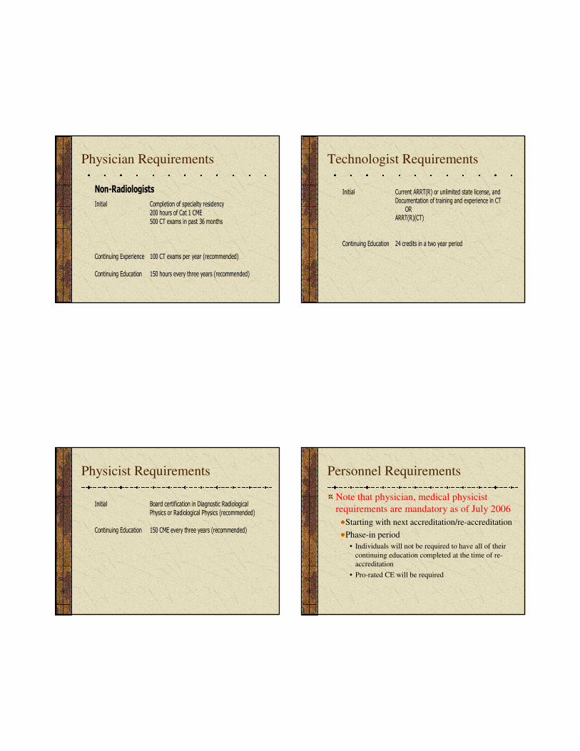
Current CTAP Statistics
Facilities active (current and under review): 881
Facilities currently accredited: 682
Units active: 1157
Units accredited: 850
0
200
400
600
800
1000
1200
Facilities Units
Active
Accredited
Failure rate: 37%(6/1/2005 – 6/30/2006)
Clinical only: 44%
Phantom only: 37%
Clinical + phantom: 19%
Physician Requirements
Radiologists
Initial Board Certification, and
300 CT exams in past 36 months
OR
Completion of a diagnostic radiology residency, and500 CT exams in past 36 months
Continuing Experience 100 CT exams per year (recommended)
Continuing Education 150 hours every three years (recommended)
2
Physician Requirements
Non-Radiologists
Initial Completion of specialty residency
200 hours of Cat 1 CME
500 CT exams in past 36 months
Continuing Experience 100 CT exams per year (recommended)
Continuing Education 150 hours every three years (recommended)
Technologist Requirements
Initial Current ARRT(R) or unlimited state license, and
Documentation of training and experience in CT
ORARRT(R)(CT)
Continuing Education 24 credits in a two year period
Physicist Requirements
Initial Board certification in Diagnostic Radiological
Physics or Radiological Physics (recommended)
Continuing Education 150 CME every three years (recommended)
Personnel Requirements
Note that physician, medical physicist
requirements are mandatory as of July 2006
Starting with next accreditation/re-accreditation
Phase-in period
• Individuals will not be required to have all of their
continuing education completed at the time of re-
accreditation
• Pro-rated CE will be required
3
Equipment Requirements
CT equipment specifications and
performance shall meet state and federal
requirements and applicable ACR
Practice Guidelines and Technical
Standards.
Quality Assurance
Policies and Procedures
Quality
Patient education
Infection control
Safety
Per ACR Policy on Quality Control and
Improvement, Safety, Infection Control
and Patient Education Concerns
Quality Assurance
Must include
Appropriateness/Outcomes analysis for
CT-guided procedures
• Diagnostic accuracy
• Complication rate
• Outcome
Equipment quality control
• Continuing QC
• Annual MP survey
Continuous QC Program
Established with Medical Physicist
Frequency of each
test
Who performs each
test
Should include
Alignment light accuracy
Slice thickness
Image quality
• Spatial resolution
• Low contrast resolution
• Image uniformity
• Noise
• Artifact evaluation
CT number accuracy
Display devices
4
Continuous QC Program
Written procedures and methods
PM scheduled, performed, documented
Results of QC program monitored annually
by MP
Corrective action
Service records and QC follow-up
documentation
Annual Medical Physics Survey
Alignment light accuracy
Alignment of table to
gantry
Table/gantry tilt
Slice positioning from
scout
Table incrementation
accuracy
Slice thickness
Image quality
Spatial resolution
Low contrast resolution
Image uniformity
Noise
Artifact evaluation
CT number
Accuracy
Linearity
Dosimetry
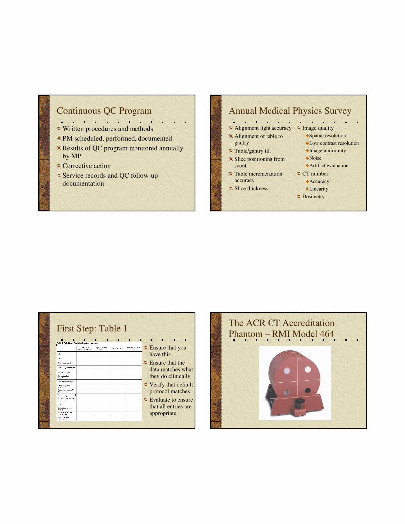
First Step: Table 1
Ensure that you
have this
Ensure that the
data matches what
they do clinically
Verify that default
protocol matches
Evaluate to ensure
that all entries are
appropriate
The ACR CT Accreditation
Phantom – RMI Model 464
5
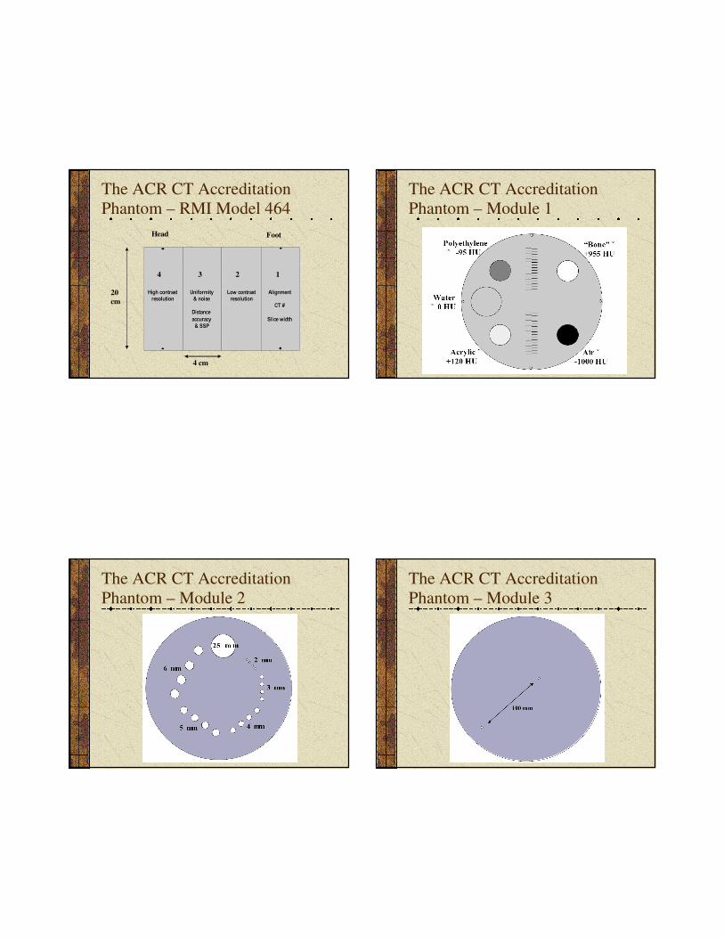
The ACR CT Accreditation
Phantom – RMI Model 464
4 3 2 1
20
cm
4 cm
Head Foot
Alignment Alignment
CT # CT #
Slice width Slice width
Low contrast Low contrast resolution resolution
Uniformity Uniformity & noise & noise
Distance Distance accuracy accuracy
& SSP & SSP
High contrast High contrast resolution resolution
The ACR CT Accreditation
Phantom – Module 1
The ACR CT Accreditation
Phantom – Module 2
The ACR CT Accreditation
Phantom – Module 3
6
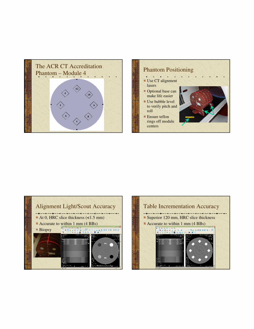
The ACR CT Accreditation
Phantom – Module 4Phantom Positioning
Use CT alignment
lasers
Optional base can
make life easier
Use bubble level
to verify pitch and
roll
Ensure teflon
rings off module
centers
Alignment Light/Scout Accuracy
At 0, HRC slice thickness (<1.5 mm)
Accurate to within 1 mm (4 BBs)
Biopsy
Table Incrementation Accuracy
Superior 120 mm, HRC slice thickness
Accurate to within 1 mm (4 BBs)
7
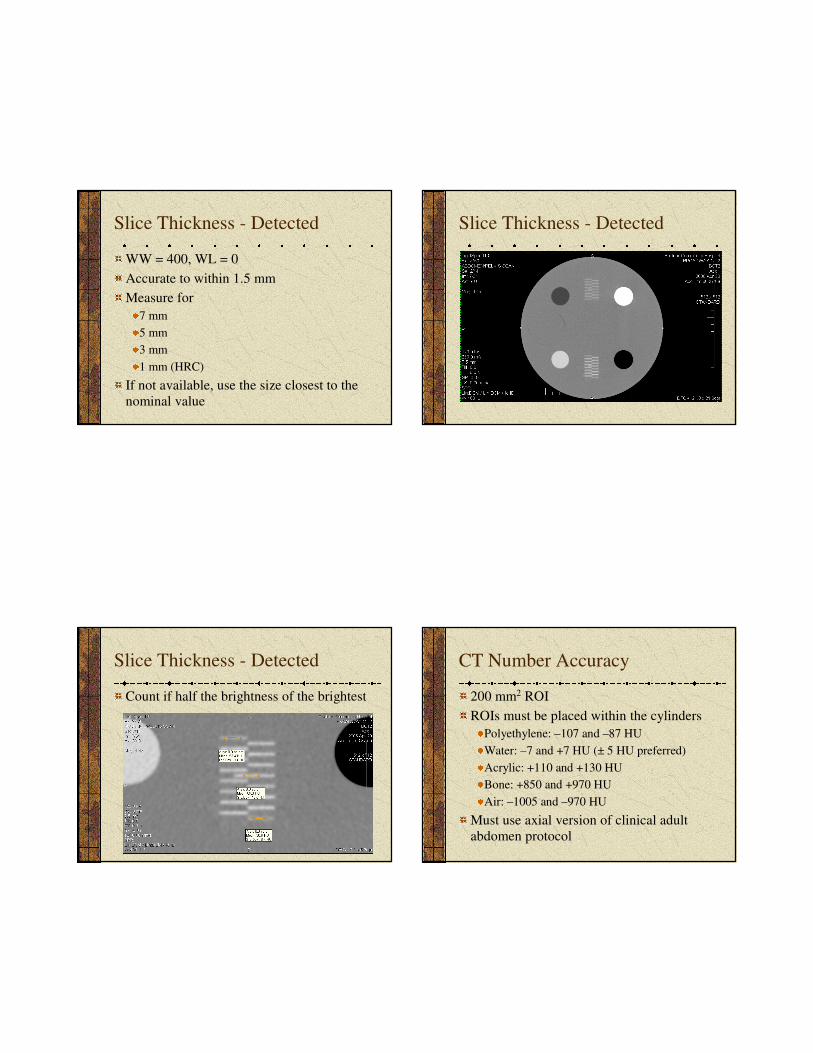
Slice Thickness - Detected
WW = 400, WL = 0
Accurate to within 1.5 mm
Measure for
7 mm
5 mm
3 mm
1 mm (HRC)
If not available, use the size closest to the
nominal value
Slice Thickness - Detected
Slice Thickness - Detected
Count if half the brightness of the brightest
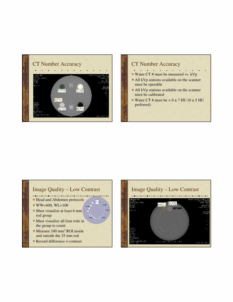
CT Number Accuracy
200 mm2 ROI
ROIs must be placed within the cylinders
Polyethylene: –107 and –87 HU
Water: –7 and +7 HU (± 5 HU preferred)
Acrylic: +110 and +130 HU
Bone: +850 and +970 HU
Air: –1005 and –970 HU
Must use axial version of clinical adult
abdomen protocol
8
CT Number Accuracy CT Number Accuracy
Water CT # must be measured vs. kVp
All kVp stations available on the scanner
must be operable
All kVp stations available on the scanner
must be calibrated
Water CT # must be = 0 ± 7 HU (0 ± 5 HU
preferred)
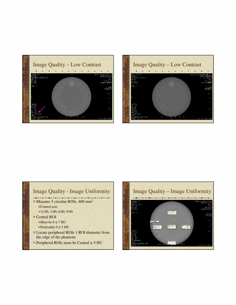
Image Quality – Low Contrast
Head and Abdomen protocols
WW=400, WL=100
Must visualize at least 6 mm
rod group
Must visualize all four rods in
the group to count.
Measure 100 mm2 ROI inside
and outside the 25 mm rod
Record difference = contrast
25 m m
6 mm
5 mm 4 mm
3 mm
2 mm
Image Quality – Low Contrast
9
Image Quality – Low Contrast Image Quality – Low Contrast
Image Quality - Image Uniformity
Measure 5 circular ROIs, 400 mm2
Central axis
12:00, 3:00, 6:00, 9:00
Central ROI
Must be 0 ± 7 HU
Preferably 0 ± 5 HU
Locate peripheral ROIs 1 ROI diameter from
the edge of the phantom
Peripheral ROIs must be Central ± 5 HU
Image Quality – Image Uniformity
10
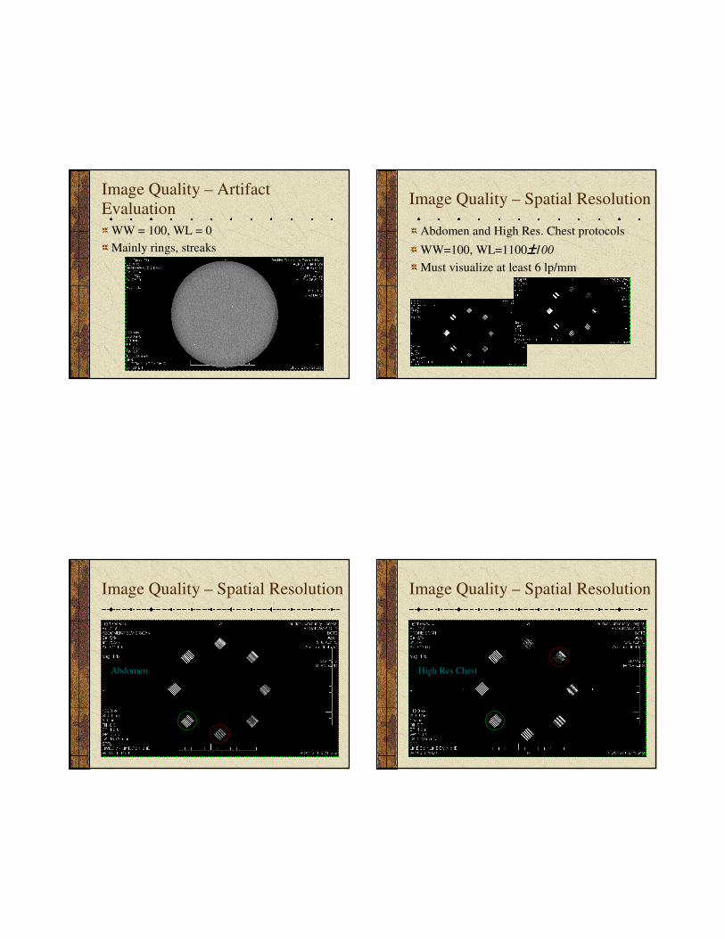
Image Quality – Artifact
Evaluation
WW = 100, WL = 0
Mainly rings, streaks
Image Quality – Spatial Resolution
Abdomen and High Res. Chest protocols
WW=100, WL=1100±±±±100
Must visualize at least 6 lp/mm
Image Quality – Spatial Resolution
Abdomen
Image Quality – Spatial Resolution
High Res Chest
11
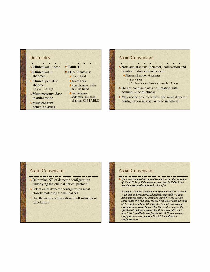
Dosimetry
Clinical adult head
Clinical adult
abdomen
Clinical pediatric
abdomen(5 y.o., ~20 kg)
Must measure dose
in axial mode
Must convert
helical to axial
Table 1
FDA phantoms:
16 cm head
32 cm body
Non-chamber holes must be filled
For pediatricabdomen, use head
phantom ON TABLE
Axial Conversion
Note actual z-axis (detector) collimation and
number of data channels used
Siemens Emotion 6 scanner
• Pitch = I/NT
• 1.2 = 14.4 mm/rot / (6 data channels * 2 mm)
Do not confuse z-axis collimation with
nominal slice thickness!
May not be able to achieve the same detector
configuration in axial as used in helical
Axial Conversion
Determine NT of detector configuration
underlying the clinical helical protocol
Select axial detector configuration most
closely matching the helical NT
Use the axial configuration in all subsequent
calculations
Axial Conversion
If an axial acquisition cannot be made using that selection
of N and T, keep T the same as described in Table 1 and
use the next smallest allowed value of N.
Example: Siemens Sensation 16 system with N = 16 and T
= 1.5 mm and reconstructed helical scan width = 5 mm.
Axial images cannot be acquired using N = 16. Use the
same value of T (1.5 mm) but the next lowest allowed value
of N, which would be 12. Thus the 12 x 1.5 mm detector
configuration would be used for the axial version of the spiral adult abdomen protocol with N = 16 and T = 1.5
mm. This is similarly true for the 16 x 0.75 mm detector
configuration (use an axial 12 x 0.75 mm detector
configuration).
12
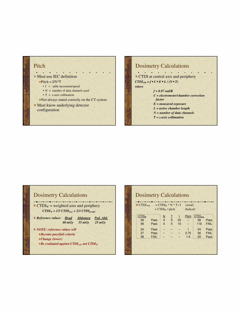
Pitch
Must use IEC definition
Pitch = I/N*T
• I = table increment/speed
• N = number of data channels used
• T = z-axis collimation
Not always stated correctly on the CT system
Must know underlying detector
configuration
Dosimetry Calculations
CTDI at central axis and periphery
CTDI100 = f • C • E • L / (N • T)
where
f = 0.87 rad/R
C = electrometer/chamber correction
factor
E = measured exposure
L = active chamber length
N = number of data channels
T = z-axis collimation
Dosimetry Calculations
CTDIW = weighted axis and periphery
CTDIW = 1/3 CTDIaxis + 2/3 CTDIperiph
Reference values: Head Abdomen Ped. Abd.
60 mGy 35 mGy 25 mGy
NOTE: reference values will
Become pass/fail criteria
Change (lower)
Be evaluated against CTDIvol, not CTDIW
Dosimetry Calculations
CTDIVOL = CTDIW * N * T / I (axial)
= CTDIW / pitch (helical)
N T I Pitch
58 Pass 4 5 20 -- 58 Pass
58 Pass 4 5 10 -- 116 FAIL
24 Pass -- -- -- 1 24 Pass
27 Pass -- -- -- 0.75 36 FAIL
38 FAIL -- -- -- 1.5 25 Pass
CTDI W CTDI VOL
13
Dosimetry Calculations
DLP (mGy-cm) = CTDIVOL (mGy) • total scan length (cm)
For ACR, assume total scan length = 17.5 cm for head
= 25.0 cm for adult abd.
= 15.0 cm for ped. abd.
Effective Dose (E) = k (mSv/mGy-cm) * DLP (mGy-cm)
Where k = 0.0023 for head
= 0.015 for adult abd.
= 0.0081 • 2.6 for ped. abd.
Reference Values
Current values derived from EUROPEAN
GUIDELINES ON QUALITY CRITERIA
FOR COMPUTED TOMOGRAPHY http://www.drs.dk/guidelines/ct/quality/mainindex.htm
New values will be based on experience
derived through the ACR CT Accreditation
Program
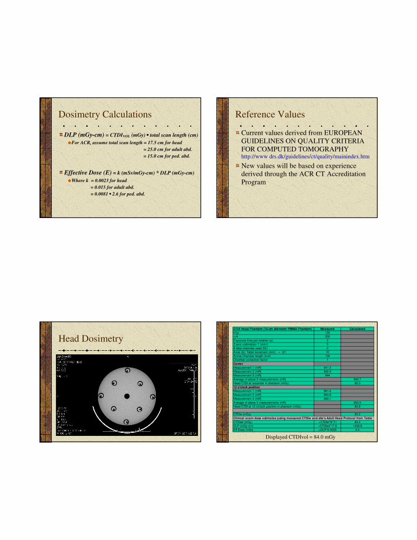
Head Dosimetry
CTDI Head Phantom (16-cm diameter PMMA Phantom) Measured Calculated
kVp 120
mA 200
Exposure time per rotation (s) 2
Z axis collimation T (mm)1 5
# data channels used (N)1 2
Axial (A): Table Increment (mm) = (I)1 10
Active Chamber length (mm) 100
Chamber correction factor 1
Center
Measurement 1 (mR) 941.3
Measurement 2 (mR) 942.9
Measurement 3 (mR) 944
Average of above 3 measurements (mR) 942.7
Head CTDI at isocenter in phantom (mGy) 82.0
12 o'clock position
Measurement 1 (mR) 961.6
Measurement 2 (mR) 963.9
Measurement 3 (mR) 966.1
Average of above 3 measurements (mR) 963.9
Head CTDI at 12 o'clock position in phantom (mGy) 83.9
CTDIw (mGy) 83.2
Clinical exam dose estimates (using measured CTDIw and site's Adult Head Protocol from Table 1)
CTDIvol (mGy) =CTDIw*N*T/I 83.2
DLP (mGy-cm) =CTDIvol*17.5 1456.8
Eff Dose (mSv) =DLP*0.0023 3.4
Displayed CTDIvol = 84.0 mGy
14
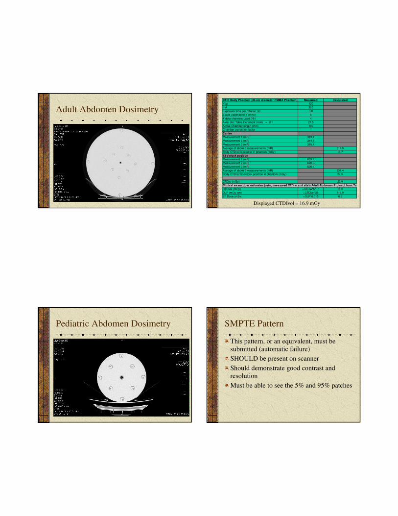
Adult Abdomen Dosimetry
CTDI Body Phantom (32-cm diameter PMMA Phantom) Measured Calculated
kVp 120
mA 320
Exposure time per rotation (s) 0.8
Z axis collimation T (mm)1 5
# data channels used (N)1 4
Axial (A): Table Increment (mm) = (I)1 27.5
Active Chamber length (mm) 100
Chamber correction factor 1
Center
Measurement 1 (mR) 313.4
Measurement 2 (mR) 314.8
Measurement 3 (mR) 315.4
Average of above 3 measurements (mR) 314.5
Body CTDI at isocenter in phantom (mGy) 13.7
12 o'clock position
Measurement 1 (mR) 653.2
Measurement 2 (mR) 620.5
Measurement 3 (mR) 620.5
Average of above 3 measurements (mR) 631.4
Body CTDI at12 o'clock position in phantom (mGy) 27.5
CTDIw (mGy) 22.9
Clinical exam dose estimates (using measured CTDIw and site's Adult Abdomen Protocol from Table 1)
CTDIvol (mGy) =CTDIw*N*T/I 16.6
DLP (mGy-cm) =CTDIvol*25 415.9
Eff Dose (mSv) =DLP*0.015 6.2
Displayed CTDIvol = 16.9 mGy
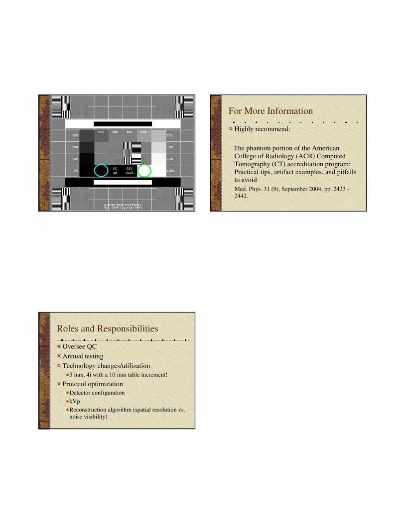
Pediatric Abdomen Dosimetry SMPTE Pattern
This pattern, or an equivalent, must be
submitted (automatic failure)
SHOULD be present on scanner
Should demonstrate good contrast and
resolution
Must be able to see the 5% and 95% patches
15
For More Information
Highly recommend:
The phantom portion of the American
College of Radiology (ACR) Computed
Tomography (CT) accreditation program:
Practical tips, artifact examples, and pitfalls
to avoid
Med. Phys. 31 (9), September 2004, pp. 2423 -2442.
Roles and Responsibilities
Oversee QC
Annual testing
Technology changes/utilization
5 mm, 4i with a 10 mm table increment!
Protocol optimization
Detector configuration
kVp
Reconstruction algorithm (spatial resolution vs.
noise visibility)


