
Outfall Redesign Study - Final Report · Cornell University: LSC Facility Outfall Redesign Study...
46
Cornell University Environmental Health and Safety October 31, 2016 NYSDEC Regional Water Engineer NYSDEC Region 7 615 Erie Boulevard West Syracuse, NY 13204-2400 Cheryl Brown Environmental Project Manager Suite 210, 395 Pine Tree Road Ithaca, New York 14850 t 607.254.8687 f. 607.255.8267 e. [email protected] www.ehs.cornell.edu Re: Final Report - Lake Source Cooling Outfall Redesign Cornell University Lake Source Cooling SPDES Permit# NY 0244741 Dear Regional Water Engineer: This transmittal satisfies the Final Report deliverable in the Schedule of Submittals for Outfall Redesign Requirements in the Lake Source Cooling (LSC) SPDES Permit #NY 0244741, which requires the submittal of a final report at 30 months after the effective date of approval (EDA) of the Outfall Redesign Study. The EDA was May 1, 2014, and the first, second, and third status reports were submitted to the NYSDEC on Dec. 22, 2014, Aug. 24, 2015, Apr. 25, 2016, respectively, with the final report due by Nov. 1, 2016. The enclosed final Outfall Redesign Report is being submitted in accordance with SPDES requirements. Please contact me should you have any questions related to this submittal. Cheryl A. Brown Environmental Project Manager Enclosure xc: Bureau of Water Permits, NYSDEC Albany Jeff Myers, NYSDEC Steve Beyers, Cornell University Edwin (Todd) Cowen, Cornell University W. S. (Lanny) Joyce, Cornell University Liz Moran, Ecologic Diversity and Inclusion are a part of Cornell University's heritage. We are a recognized employer and educator valuing AA/EEO, Protected Veterans, and Individuals with Disabilities.
-
Upload
nguyenminh -
Category
Documents
-
view
214 -
download
0
Transcript of Outfall Redesign Study - Final Report · Cornell University: LSC Facility Outfall Redesign Study...
Cornell University Environmental Health and Safety
October 31, 2016
NYSDEC Regional Water Engineer NYSDEC Region 7 615 Erie Boulevard West Syracuse, NY 13204-2400
Cheryl Brown Environmental Project Manager Suite 210, 395 Pine Tree Road Ithaca, New York 14850 t 607.254.8687 f. 607.255.8267 e. [email protected] www.ehs.cornell.edu
Re: Final Report - Lake Source Cooling Outfall Redesign Cornell University Lake Source Cooling SPDES Permit# NY 0244741
Dear Regional Water Engineer:
This transmittal satisfies the Final Report deliverable in the Schedule of Submittals for Outfall Redesign Requirements in the Lake Source Cooling (LSC) SPDES Permit #NY 0244741, which requires the submittal of a final report at 30 months after the effective date of approval (EDA) of the Outfall Redesign Study. The EDA was May 1, 2014, and the first, second, and third status reports were submitted to the NYSDEC on Dec. 22, 2014, Aug. 24, 2015, Apr. 25, 2016, respectively, with the final report due by Nov. 1, 2016.
The enclosed final Outfall Redesign Report is being submitted in accordance with SPDES requirements. Please contact me should you have any questions related to this submittal.
j~[--Cheryl A. Brown Environmental Project Manager
Enclosure
xc: Bureau of Water Permits, NYSDEC Albany Jeff Myers, NYSDEC Steve Beyers, Cornell University Edwin (Todd) Cowen, Cornell University W. S. (Lanny) Joyce, Cornell University Liz Moran, Ecologic
Diversity and Inclusion are a part of Cornell University's heritage. We are a recognized employer and educator valuing AA/EEO, Protected Veterans, and Individuals with Disabilities.
Cornell Lake Source Cooling Facility Outfall Redesign Study Final Report
SPDES Permit NY0244741 Special Condition
Cornell University October 31, 2016

Cornell University: LSC Facility Outfall Redesign Study Final Report
1
Table of Contents
Executive Summary ....................................................................................................................................... 2
1. Introduction .......................................................................................................................................... 7
1.1. Objective ....................................................................................................................................... 7
1.2. Structure of this Document .......................................................................................................... 7
2. Task 1: Evaluate the Mixing Zone of the LSC Outfall ............................................................................ 9
2.1. Introduction .................................................................................................................................. 9
2.2. Numerical Grid ............................................................................................................................ 10
2.3. Influence of the LSC Outfall Diffuser on Mixing .......................................................................... 11
2.4. Shelf Residence Time .................................................................................................................. 14
2.5. Mixing Zone of the As-Built LSC Outfall ...................................................................................... 16
3. Task 2: Identify an Alternative Outfall Location in the Class AA Segment of Cayuga Lake................. 22
3.1. Calculation of Photic Zone Depth ............................................................................................... 22
3.2. Modeling Plume Behavior at an Alternative Discharge Location ............................................... 25
4. Task 3: Conceptual Design of the Outfall Extension ........................................................................... 30
4.1. Overview ..................................................................................................................................... 30
4.2. Basis of Conceptual Design ......................................................................................................... 30
4.3. Conceptual Cost Estimates ......................................................................................................... 31
4.4. Project Schedule ......................................................................................................................... 33
5. Task 4: Environmental Impact Assessment ........................................................................................ 36
5.1. Water Quality Modeling ............................................................................................................. 36
5.2. Phosphorus and Phytoplankton .................................................................................................. 37
5.3. Hydrodynamics ........................................................................................................................... 38
5.4. Construction and Operations-Related Environmental Factors ................................................... 38
5.5. Institutional Factors .................................................................................................................... 38
6. Conclusions ......................................................................................................................................... 39
7. References .......................................................................................................................................... 40
Appendix A

Cornell University: LSC Facility Outfall Redesign Study Final Report
2
Executive Summary
Objective
The objective of this Outfall Redesign Report is to comply with one of the conditions set forth in the
State Pollution Discharge Elimination System (SPDES) permit NY0244741 issued to Cornell University in
May 2013 by New York State Department of Environmental Conservation (NYSDEC) for continued
operation of the Lake Source Cooling (LSC) Facility. The relevant permit condition required Cornell to
complete an Outfall Redesign Study to:
“…evaluate potential alternative sites for relocating the discharge from Outfall 001 to a location
within the Class AA segment of Cayuga Lake (as depicted by Transect A-A’ on the Monitoring
Locations map, and defined in 6 NYCRR Part 898.4, Table 1, item 227). The requirement of the
Study shall be to evaluate the current mixing zone of the discharge, identify one or more
discharge locations, in waters of sufficient depth to ensure that the discharge plume remains
below the photic zone, and to determine that the discharge will not contribute to an impairment
of the designated uses of the Lake.”
Cornell University submitted a workplan detailing the assumptions and technical approach for
completing the Outfall Redesign Study; this workplan was approved by NYSDEC on May 1, 2014. Interim
status reports were submitted as required on January 1, 2015; September 1, 2015; and May 1, 2016.
With this Final Report, Cornell University has now completed all obligations related to this permit
condition.
Project Team
Professor Edwin A. (Todd) Cowen and Dr. Alexandra (Allie) King of the Cornell University School of Civil
and Environmental Engineering’s DeFrees Hydraulic Laboratory, which resides in the College of
Engineering, are the Principal Investigators of the Outfall Redesign Study. Dr. Cowen and Dr. King have
been supported in their efforts by other members of the Cayuga Lake Modeling Project team.
Researchers from the Upstate Freshwater Institute provided calculations of the lake’s photic zone, and
Clough Harbor Associates prepared the conceptual design and cost estimates for an extended outfall.
Current Mixing Zone of LSC Return Flow
Technical Approach Drs. Cowen and King completed numerical simulations of the water motion (hydrodynamics) of Cayuga
Lake using the free surface hydrodynamic model Si3D (Rueda 2001; Smith 2006; Rueda and Cowen
2005; Rueda et al. 2008; Acosta et al. 2015). Numerical simulations of the hydrodynamics of Cayuga Lake
using this 3D model were conducted in order to capture and quantify the spatial-temporal evolution of
the LSC outfall plume in response to the various forcing functions. Model runs were selected to examine

Cornell University: LSC Facility Outfall Redesign Study Final Report
3
the thermal plume under various conditions of LSC facility performance, wind conditions, and tributary
inflows. The model output enabled the research team to estimate the water residence time on the
lake’s southern shelf.
The 3D hydrodynamic model was set up, calibrated, and validated using site-specific data. These data
include the detailed bathymetric surveys completed for the construction of the Lake Source Cooling
intake and outfall pipes, the long-term water temperature record collected at the piling cluster, the
long-term temperature record at the LSC intake, data from the point sources discharging to southern
Cayuga Lake, and additional field observations including a gridding study conducted specifically for the
purposes of model validation.
Findings For the LSC discharge, the flow induced by the outfall is an order of magnitude larger than the flow from
the outfall itself. The effect of back entrainment is most significant and affects the circulation and
residence time of water on the shelf. Residence time of water on the shelf under summer conditions
was calculated for three meteorological conditions using the Si3D model: high tributary flows/high wind;
low tributary flow/high wind; and low tributary flow/low wind. Simulations were run with the LSC
discharge in its current location, and also at a location north of the 303(d) line, for each of the
meteorological scenarios, to allow for comparison of shelf residence times between as-built and
extended outfall cases.
Residence time of water on the shelf is short (on the order of day to days), and highly influenced by the
LSC return flow. Residence time is calculated at five locations within the shelf; results vary among the
sites based on circulation and mixing patterns. The longest residence time is projected to occur during
prolonged periods of low wind and low tributary inflows. Under those conditions, the average water
residence time at the modeled locations on the shelf (to the 6m depth contour) is projected to be 1.8
days. Extending the outfall to deeper water would lengthen water residence time to about 2.9 days, a
60% increase.
The model team defined the mixing zone associated with the LSC discharge based on the thermal plume.
As evident from the visualizations included in the report, the mixing zone is small.
Alternative Discharge Location
Technical Approach The permit requires Cornell to identify an alternative outfall location within the Class AA segment of
Cayuga Lake (i.e., north of the 303(d) line) where the LSC return flow would remain below the photic
zone, defined as the depth where 1% of the photosynthetically active radiation (PAR) striking the lake
surface remains detectable. Because light penetration is affected by materials dissolved and suspended
in the water column, photic zone depth is variable. Ten years of light penetration data collected from
Cayuga Lake were analyzed to characterize photic zone in the Class AA segment of Cayuga Lake; the
upper 75% of the statistical distribution of the data, 14.9m, was selected as the critical photic zone
depth between May 1st and October 31st.
Cornell University: LSC Facility Outfall Redesign Study Final Report
4
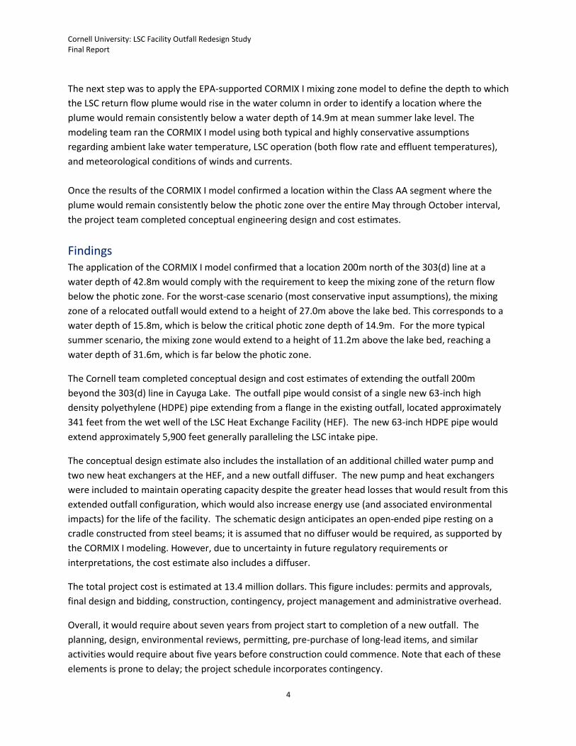
The next step was to apply the EPA-supported CORMIX I mixing zone model to define the depth to which
the LSC return flow plume would rise in the water column in order to identify a location where the
plume would remain consistently below a water depth of 14.9m at mean summer lake level. The
modeling team ran the CORMIX I model using both typical and highly conservative assumptions
regarding ambient lake water temperature, LSC operation (both flow rate and effluent temperatures),
and meteorological conditions of winds and currents.
Once the results of the CORMIX I model confirmed a location within the Class AA segment where the
plume would remain consistently below the photic zone over the entire May through October interval,
the project team completed conceptual engineering design and cost estimates.
Findings The application of the CORMIX I model confirmed that a location 200m north of the 303(d) line at a
water depth of 42.8m would comply with the requirement to keep the mixing zone of the return flow
below the photic zone. For the worst-case scenario (most conservative input assumptions), the mixing
zone of a relocated outfall would extend to a height of 27.0m above the lake bed. This corresponds to a
water depth of 15.8m, which is below the critical photic zone depth of 14.9m. For the more typical
summer scenario, the mixing zone would extend to a height of 11.2m above the lake bed, reaching a
water depth of 31.6m, which is far below the photic zone.
The Cornell team completed conceptual design and cost estimates of extending the outfall 200m
beyond the 303(d) line in Cayuga Lake. The outfall pipe would consist of a single new 63-inch high
density polyethylene (HDPE) pipe extending from a flange in the existing outfall, located approximately
341 feet from the wet well of the LSC Heat Exchange Facility (HEF). The new 63-inch HDPE pipe would
extend approximately 5,900 feet generally paralleling the LSC intake pipe.
The conceptual design estimate also includes the installation of an additional chilled water pump and
two new heat exchangers at the HEF, and a new outfall diffuser. The new pump and heat exchangers
were included to maintain operating capacity despite the greater head losses that would result from this
extended outfall configuration, which would also increase energy use (and associated environmental
impacts) for the life of the facility. The schematic design anticipates an open-ended pipe resting on a
cradle constructed from steel beams; it is assumed that no diffuser would be required, as supported by
the CORMIX I modeling. However, due to uncertainty in future regulatory requirements or
interpretations, the cost estimate also includes a diffuser.
The total project cost is estimated at 13.4 million dollars. This figure includes: permits and approvals,
final design and bidding, construction, contingency, project management and administrative overhead.
Overall, it would require about seven years from project start to completion of a new outfall. The
planning, design, environmental reviews, permitting, pre-purchase of long-lead items, and similar
activities would require about five years before construction could commence. Note that each of these
elements is prone to delay; the project schedule incorporates contingency.
Cornell University: LSC Facility Outfall Redesign Study Final Report
5
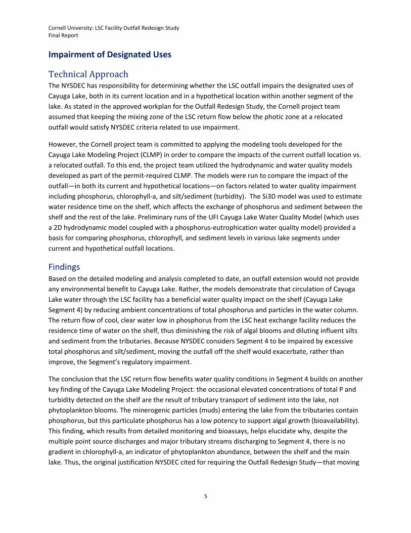
Impairment of Designated Uses
Technical Approach The NYSDEC has responsibility for determining whether the LSC outfall impairs the designated uses of
Cayuga Lake, both in its current location and in a hypothetical location within another segment of the
lake. As stated in the approved workplan for the Outfall Redesign Study, the Cornell project team
assumed that keeping the mixing zone of the LSC return flow below the photic zone at a relocated
outfall would satisfy NYSDEC criteria related to use impairment.
However, the Cornell project team is committed to applying the modeling tools developed for the
Cayuga Lake Modeling Project (CLMP) in order to compare the impacts of the current outfall location vs.
a relocated outfall. To this end, the project team utilized the hydrodynamic and water quality models
developed as part of the permit-required CLMP. The models were run to compare the impact of the
outfall—in both its current and hypothetical locations—on factors related to water quality impairment
including phosphorus, chlorophyll-a, and silt/sediment (turbidity). The Si3D model was used to estimate
water residence time on the shelf, which affects the exchange of phosphorus and sediment between the
shelf and the rest of the lake. Preliminary runs of the UFI Cayuga Lake Water Quality Model (which uses
a 2D hydrodynamic model coupled with a phosphorus-eutrophication water quality model) provided a
basis for comparing phosphorus, chlorophyll, and sediment levels in various lake segments under
current and hypothetical outfall locations.
Findings Based on the detailed modeling and analysis completed to date, an outfall extension would not provide
any environmental benefit to Cayuga Lake. Rather, the models demonstrate that circulation of Cayuga
Lake water through the LSC facility has a beneficial water quality impact on the shelf (Cayuga Lake
Segment 4) by reducing ambient concentrations of total phosphorus and particles in the water column.
The return flow of cool, clear water low in phosphorus from the LSC heat exchange facility reduces the
residence time of water on the shelf, thus diminishing the risk of algal blooms and diluting influent silts
and sediment from the tributaries. Because NYSDEC considers Segment 4 to be impaired by excessive
total phosphorus and silt/sediment, moving the outfall off the shelf would exacerbate, rather than
improve, the Segment’s regulatory impairment.
The conclusion that the LSC return flow benefits water quality conditions in Segment 4 builds on another
key finding of the Cayuga Lake Modeling Project: the occasional elevated concentrations of total P and
turbidity detected on the shelf are the result of tributary transport of sediment into the lake, not
phytoplankton blooms. The minerogenic particles (muds) entering the lake from the tributaries contain
phosphorus, but this particulate phosphorus has a low potency to support algal growth (bioavailability).
This finding, which results from detailed monitoring and bioassays, helps elucidate why, despite the
multiple point source discharges and major tributary streams discharging to Segment 4, there is no
gradient in chlorophyll-a, an indicator of phytoplankton abundance, between the shelf and the main
lake. Thus, the original justification NYSDEC cited for requiring the Outfall Redesign Study—that moving

Cornell University: LSC Facility Outfall Redesign Study Final Report
6
the outfall would reduce phosphorus and phytoplankton levels in the impaired Segment of Cayuga
Lake—has been undermined.
Conclusions
The hydrodynamic and water quality models project that a relocated outfall would offer no sustained
reduction in Cayuga Lake’s phytoplankton, either on or off the shelf. In fact, moving the outfall off of
the shelf is forecast to exacerbate, rather than improve, the water quality parameters for which NYSDEC
designates southern Cayuga Lake as impaired.
There are other adverse environmental impacts of an extended outfall. In-lake construction would
disturb sediments and the benthic community as well as temporarily restrict recreational access. The
manufacture, shipping, and assembly of the materials needed to extend the outfall represent additional
environmental impacts. Over the long term, an extended outfall would result in higher pumping heads
and more energy use, for which there are adverse environmental impacts. Increased energy use with no
offsetting benefit is in direct opposition to the University’s goals for carbon neutrality as well as New
York State and federal commitments to climate action. Consequently, any environmental rationale for
requiring an extended outfall simply does not exist.
There are institutional consequences as well. An outfall extension would represent a significant
economic burden for Cornell, a not-for-profit institution of higher education that includes State-
supported colleges. The University is committed to investing in environmental projects that provide an
ecosystem benefit, not increase the risk of harm to air quality, water quality, or climate. The review and
approval process to extend the outfall would require a significant diversion of resources by the
regulatory community, including local and regional officials of at least four separate agencies.
Cornell has concluded that there are no environmental or regulatory compliance benefits to an outfall
extension. Rather, the short-term construction impacts and long-term increased energy usage would be
detrimental. Such an action would go against University goals for stewardship, NYSDEC commitment to
reducing greenhouse gas emissions, and our national policy related to climate change. The current
operation provides a net water quality benefit to southern Cayuga Lake and enables the University to
advance toward carbon neutrality. For these reasons, Cornell concludes that an outfall extension is
counter indicated as a means to ensure that the LSC facility does not contribute to an impairment of
Cayuga Lake.
Cornell University: LSC Facility Outfall Redesign Study Final Report
7
Final Report: Outfall Redesign Study
1. Introduction
1.1. Objective The objective of this study and report is to comply with one of the conditions set forth in the State
Pollution Discharge Elimination System (SPDES) permit NY0244741 issued to Cornell University in May
2013 by New York State Department of Environmental Conservation (NYSDEC) for continued operation
of the Lake Source Cooling (LSC) Facility. The relevant permit condition required Cornell to complete an
Outfall Redesign Study to:
“…evaluate potential alternative sites for relocating the discharge from Outfall 001 to a location
within the Class AA segment of Cayuga Lake (as depicted by Transect A-A’ on the Monitoring
Locations map, and defined in 6 NYCRR Part 898.4, Table 1, item 227). The requirement of the
Study shall be to evaluate the current mixing zone of the discharge, identify one or more
discharge locations, in waters of sufficient depth to ensure that the discharge plume remains
below the photic zone, and to determine that the discharge will not contribute to an impairment
of the designated uses of the Lake.”
Cornell University submitted a workplan detailing the assumptions and technical approach for
completing the Outfall Redesign Study; this workplan was approved by NYSDEC on May 1, 2014. Interim
status reports were submitted as required on January 1, 2015; September 1, 2015; and May 1, 2016.
1.2. Structure of this Document The 2013 SPDES permit for continued operation of the LSC facility requires three specific tasks related to
the Outfall Redesign Study to be completed and reported on in this final submittal:
Task 1: Evaluate the existing mixing zone of the LSC outfall as it returns Cayuga Lake water to
the shelf (Class A) segment (Section 2).
Task 2: Identify an alternative outfall location within Cayuga Lake’s Class AA segment that is
deep enough to keep the outfall mixing zone below the photic zone (Section 3).
Task 3: Complete the conceptual design of a relocated outfall (Section 4).
The Cornell team added a fourth task:
Task 4: Compare the environmental impacts of return flow from the LSC facility using the
existing outfall vs. relocating the outfall to deeper water (Section 5).
This fourth task was included to inform the University’s decision referenced on Page 9 of 13 of the
SPDES permit, which incorporates the other required elements of the Cayuga Lake Modeling Project:

Cornell University: LSC Facility Outfall Redesign Study Final Report
8
“In the event that an outfall relocation is determined by the permittee to be the most practical
approach to ensure that the discharge will not contribute to an impairment (as determined by
the Department) of the designated use of the receiving water, and to comply with the final
phosphorus effluent limit or the Cayuga Lake TMDL as listed on the following page, the
permittee shall submit preliminary and final design reports and complete construction of the
approved redesigned outfall in accordance with the approved implementation schedule in the
Outfall Redesign Study.
The conclusions of the Outfall Redesign Study Report are presented in Section 6, which is followed by
Section 7: References and Appendix A.

Cornell University: LSC Facility Outfall Redesign Study Final Report
9
2. Task 1: Evaluate the Mixing Zone of the LSC Outfall
2.1. Introduction Professor Edwin A. (Todd) Cowen and Dr. Alexandra (Allie) King of the Cornell University School of Civil
and Environmental Engineering’s DeFrees Hydraulic Laboratory, which resides in the College of
Engineering, completed numerical simulations of the water motion (hydrodynamics) of Cayuga Lake
using the three-dimensional (3D) free surface hydrodynamic model Si3D (Rueda 2001; Smith 2006;
Rueda and Cowen 2005; Rueda et al. 2008; Acosta et al. 2015). While the long, narrow, deep geometry
of Cayuga Lake ensures that lake-wide processes are largely two-dimensional (2D), and thus a 2D model
is appropriate for lake-wide phenomena, the southern shelf is no longer than its width; this results in
high lateral gradients and 3D flow and transport processes. Therefore, 3D modeling is required to
capture and quantify the spatial-temporal evolution of the LSC outfall plume, its hydrodynamic impact
on the southern shelf, and, in particular, its impact on shelf residence times in response to various
physical forcing scenarios. Model runs were designed and executed to examine the thermal plume
under various conditions of LSC facility performance, wind conditions, and tributary inflows. The model
output enabled the research team to estimate the water residence time on the lake’s southern shelf.
The 3D hydrodynamic model was set up, calibrated, and validated using site-specific data. These data
include the detailed bathymetric surveys completed for the construction of the LSC intake and outfall
pipes, the long-term water temperature record collected at the piling cluster, high frequency water
temperature measurements from thermistor strings deployed through the water column, the long-term
water temperature record at the LSC intake, data from the point sources discharging to southern Cayuga
Lake, and additional field observations including a gridding study conducted specifically for the purposes
of model validation.
The detailed description of the field measurements, model development and enhancements, model
calibration, model validation, and results of simulations are included in Appendix A. In this section, the
effect of the LSC outfall on water residence time on the shelf (Cayuga Lake Segment 4) are summarized
and compared with water residence time on the shelf if the outfall were relocated north of the 303(d)
line. Provisional results are presented showing the mixing zone of the as-built outfall. This report
includes model results using a low resolution (125m) grid size for residence time studies and the project
team is confident in their general findings pertaining to residence time. The mixing zone results are
based in high resolution (25m) simulations that are still undergoing validation. Both the 125m and 25m
simulations will be subject to final calibration and validation. For research and academic purposes,
Professor Cowen and Dr. King will continue to develop the Si3D model in order to characterize the
circulation of Cayuga Lake. These results and associated publications will be provided to NYSDEC as a
separate deliverable .
Cornell University: LSC Facility Outfall Redesign Study Final Report
10
2.2. Numerical Grid Multiple data sources were used to characterize Cayuga Lake’s bathymetry and supply the depth
information needed to set up the numerical grid for the 3D model. The numerical grid defines the
locations where velocities, temperatures, and tracer concentrations are evaluated by the numerical
model. Si3D employs a staggered Cartesian grid, meaning the cells are rectangular prisms, fluxes are
computed at cell faces, and scalar quantities are evaluated at the center of each cell. Tributaries were
included in the grid up to the location of the first hydraulic jump upstream of the lake, which was
identified by the Cayuga Lake Modeling Project (CLMP) team as part of a 2012 field survey. Above this
first hydraulic jump, flow is supercritical, meaning surface waves cannot propagate upstream.
To resolve the lateral mixing, back entrainment, and resulting circulation on the shelf caused by the LSC
outfall as well as the tributary inflows, the modeling team determined that a resolution of 25m x 25m is
required in the horizontal plane, and a resolution of 0.1m is required in the vertical direction. This high
resolution is not computationally feasible for the entire lake; therefore, the modelers developed a
nested gridding scheme. The entire lake is modeled using a 125m x 125m grid, and the shallow southern
shelf is modeled in greater detail using a 25m x 25m grid. The 125m x 125m grid is called the “coarse”,
“low resolution”, or “LR” grid, and the 25m x 25m grid is called the “fine”, “high resolution”, or “HR”
grid. The LR simulations were run first, followed by the HR simulations using the LR results as input: the
boundary conditions at the open boundary located along the north end of the HR grid are specified
using the predictions of the LR simulations at the location of that boundary. Details of the numerical
implementation of the nested boundary are documented in Acosta et al. (2015).
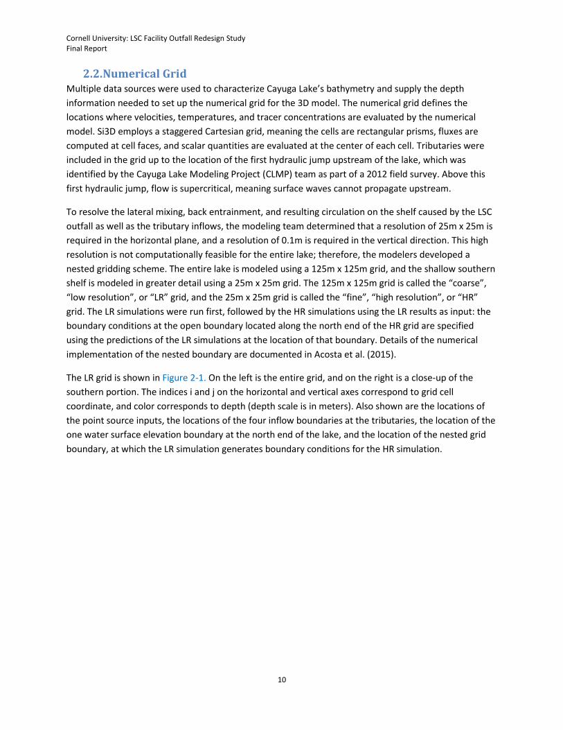
The LR grid is shown in Figure 2-1. On the left is the entire grid, and on the right is a close-up of the
southern portion. The indices i and j on the horizontal and vertical axes correspond to grid cell
coordinate, and color corresponds to depth (depth scale is in meters). Also shown are the locations of
the point source inputs, the locations of the four inflow boundaries at the tributaries, the location of the
one water surface elevation boundary at the north end of the lake, and the location of the nested grid
boundary, at which the LR simulation generates boundary conditions for the HR simulation.

Cornell University: LSC Facility Outfall Redesign Study Final Report
11
Figure 2-1. Schematic representation of the low resolution grid used in the Si3D model.
2.3. Influence of the LSC Outfall Diffuser on Mixing The SPDES permit conditions required Cornell to delineate the existing mixing zone of the LSC outfall,
which returns water to southern Cayuga Lake’s shelf (regulatory Segment 4) via a multiport diffuser.
The 3D model was used to delineate the mixing zone under various forcing scenarios. Modifications of
the 3D model to include the impact of the LSC outfall on shelf hydrodynamics were based on the
CORMIX II framework. CORMIX II is a USEPA-supported mixing zone model and decision support system
for environmental impact assessment of regulatory mixing zones resulting from continuous point source
discharges. CORMIX II was developed specifically for assessing multiport diffusers and classifies
multiport diffuser plumes using a decision tree documented in Akar and Jirka (1991). The flow class
depends on the geometry of the diffuser, the effluent flow rate, the effluent density, and characteristics
of the receiving water at the diffuser site. The LSC diffuser plume behaves as flow class MNU7 when it is
negatively buoyant, meaning that the return flow is cooler than ambient conditions. When the return
flow is warmer than ambient (winter conditions) it is positively buoyant and behaves as flow class MU2.
Cornell University: LSC Facility Outfall Redesign Study Final Report
12
The equations underlying CORMIX II predict plume behavior, including its dilution, centerline velocity,
and half- width. The modeling team increased the accuracy of the intermediate-field equations for these
parameters by including the effect of friction, following Lee and Jirka (1980). The Lee and Jirka equations
were used as the basis for inclusion of the LSC outfall within the 3D model.
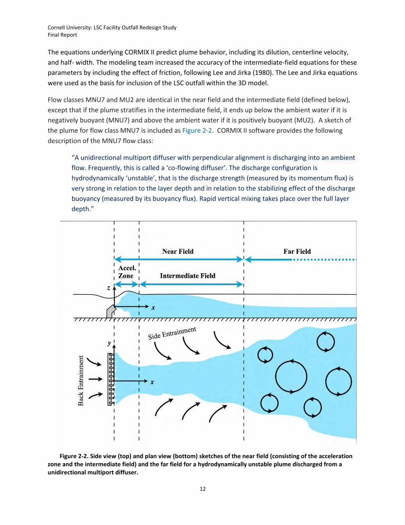
Flow classes MNU7 and MU2 are identical in the near field and the intermediate field (defined below),
except that if the plume stratifies in the intermediate field, it ends up below the ambient water if it is
negatively buoyant (MNU7) and above the ambient water if it is positively buoyant (MU2). A sketch of
the plume for flow class MNU7 is included as Figure 2-2. CORMIX II software provides the following
description of the MNU7 flow class:
“A unidirectional multiport diffuser with perpendicular alignment is discharging into an ambient
flow. Frequently, this is called a ‘co-flowing diffuser’. The discharge configuration is
hydrodynamically ‘unstable’, that is the discharge strength (measured by its momentum flux) is
very strong in relation to the layer depth and in relation to the stabilizing effect of the discharge
buoyancy (measured by its buoyancy flux). Rapid vertical mixing takes place over the full layer
depth.”
Figure 2-2. Side view (top) and plan view (bottom) sketches of the near field (consisting of the acceleration zone and the intermediate field) and the far field for a hydrodynamically unstable plume discharged from a unidirectional multiport diffuser.
Cornell University: LSC Facility Outfall Redesign Study Final Report
13
For the LSC discharge, the flow induced by the outfall is an order of magnitude larger than the flow from
the outfall itself. The effect of back entrainment is most significant and affects the circulation and
residence time of water on the shelf.
The investigators embedded the LSC outfall within Si3D by
(1) adding sources of mass, momentum, active (temperature), and passive (tracer) scalars to the
governing equations;
(2) modifying the horizontal mixing coefficients (turbulent eddy viscosity and turbulent eddy
diffusivity) to produce lateral mixing and corresponding dilution predicted for the MNU7 flow
class by Lee and Jirka (1980).
Provided that (1) is implemented and the plume is adequately resolved in the horizontal dimensions
(using a 25m x 25m horizontal resolution), the back entrainment and near-field behavior predicted by
CORMIX II is captured automatically by the 3D model. The strong lateral entrainment (or “side
entrainment”) predicted by Lee and Jirka (1980) within the intermediate field must be enforced
indirectly through modification of the horizontal mixing coefficients within Si3D, i.e., through (2). Details
of implementation of (1) and (2) are described in Appendix A.
Before applying the 3D model—modified to include the effects of the LSC outfall—to Cayuga Lake, the
investigators conducted tests to verify that it obtained the correct analytical solutions within a simple
rectangular basin of uniform depth. The analytical solutions used for comparison are found in Lee and
Jirka (1980) and represent a modification of the CORMIX II equations for flow class MNU7 within the
unstratified region to account for bed friction. The investigators found excellent agreement, as displayed
in Figure 2-3, for a neutrally buoyant effluent. For a negatively buoyant effluent, plume behavior is in
good agreement with analytical solutions in the near field and the unstratified portion of the
intermediate field. The investigators found discrepancies with the reference solutions in the stratified
portion of the intermediate field, but in this region the reference solutions are based on scant empirical
data, and it is likely the 3D model predicts more physically accurate behavior.

Cornell University: LSC Facility Outfall Redesign Study Final Report
14
Figure 2-3. Comparison of Si3D to Lee & Jirka (1980) (theoretical) solutions for u (east velocity component) and v (north velocity component) for a neutrally buoyant discharge at steady state. Note the theoretical solution is not defined for y<0. These Si3D velocities are depth-averaged.
2.4. Shelf Residence Time Hydraulic residence time is defined as the amount of time a parcel of water remains within an aquatic
system. The individual molecules within a parcel of water will leave the system at different times – thus
residence time is a stochastic quantity, having a mean, standard deviation, and higher order statistics. In
the approved workplan for the Outfall Redesign Study, three conditions were identified as most
informative to characterizing the effect of the LSC outfall on residence time on the shelf.
Summer stratification regime, high tributary flows (for summer), high summer point source flows, strong winds
Summer stratification regime, low tributary flows (for summer), high summer point source flows, low winds
Summer stratification regime, low tributary flows (for summer), high summer point source flows, strong winds
Cornell University: LSC Facility Outfall Redesign Study Final Report
15
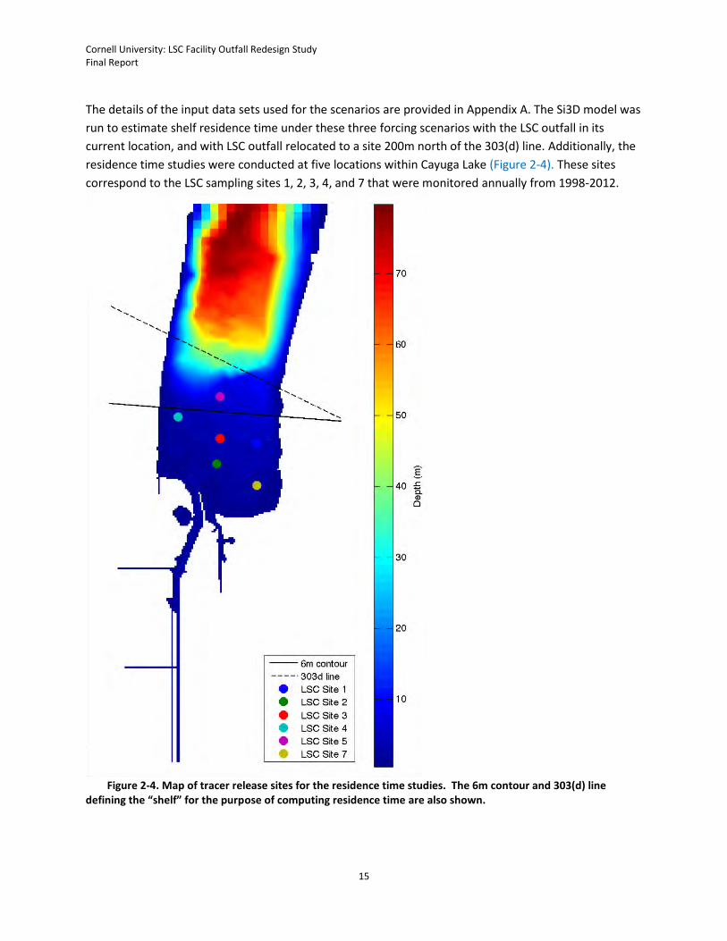
The details of the input data sets used for the scenarios are provided in Appendix A. The Si3D model was
run to estimate shelf residence time under these three forcing scenarios with the LSC outfall in its
current location, and with LSC outfall relocated to a site 200m north of the 303(d) line. Additionally, the
residence time studies were conducted at five locations within Cayuga Lake (Figure 2-4). These sites
correspond to the LSC sampling sites 1, 2, 3, 4, and 7 that were monitored annually from 1998-2012.
Figure 2-4. Map of tracer release sites for the residence time studies. The 6m contour and 303(d) line
defining the “shelf” for the purpose of computing residence time are also shown.
Cornell University: LSC Facility Outfall Redesign Study Final Report
16
In all conditions, the presence of the LSC outfall within Segment 4 has a positive impact on decreased
residence time of water on the shelf as delineated by the 6m contour (Table 2-1) or by the regulatory
303(d) line (Table 2-2).
Table 2-1. Mean residence time, using the 6m depth contour as the northern border of the “shelf” system
for the three meteorological scenarios and for both as-built and extended LSC outfall scenarios. These results are preliminary pending finalization of the HR model.
High Flow / High Wind Low Flow / High Wind Low Flow / Low Wind
LSC Site As built Extended As built Extended As built Extended 1 0.32 days 0.57 days 0.40 days 1.0 days 1.5 days 1.8 days 2 0.52 days 0.71 days 0.65 days 1.6 days 1.7 days 3.0 days 3 0.55 days 0.91 days 0.67 days 1.6 days 1.7 days 2.8 days 4 0.97 days 1.2 days 1.2 days 1.8 days 2.6 days 4.2 days 7 0.45 days 0.71 days 0.55 days 1.5 days 1.6 days 2.8 days
Average 0.56 days 0.82 days 0.69 days 1.5 days 1.8 days 2.9 days
Table 2-2. Mean residence time, using the 303d line as the northern border of the “shelf” system for the three meteorological scenarios and for as-built and extended LSC outfall scenarios. These results are preliminary pending finalization of the HR model.
High Flow / High Wind Low Flow / High Wind Low Flow / Low Wind
LSC Site As built Extended As built Extended As built Extended 1 0.83 days 1.4 days 0.98 days 2.1 days 3.5 days 3.7 days 2 0.99 days 1.3 days 1.2 days 2.4 days 3.4 days 4.8 days 3 1.1 days 1.5 days 1.2 days 2.5 days 3.4 days 4.8 days 4 1.5 days 1.7 days 1.7 days 2.5 days 4.0 days 6.3 days 7 0.89 days 1.3 days 1.1 days 2.3 days 3.5 days 4.6 days
Average 1.1 days 1.4 days 1.2 days 2.4 days 3.6 days 4.8 days
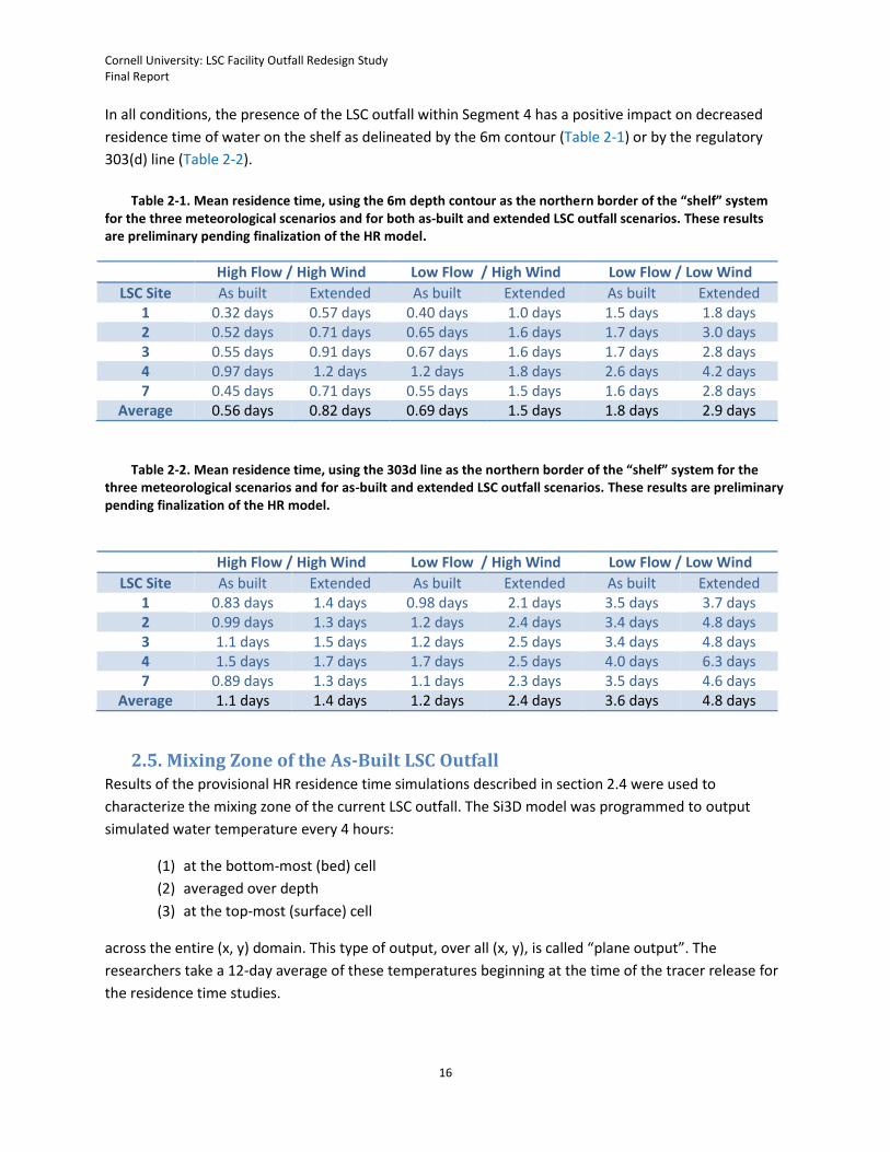
2.5. Mixing Zone of the As-Built LSC Outfall Results of the provisional HR residence time simulations described in section 2.4 were used to
characterize the mixing zone of the current LSC outfall. The Si3D model was programmed to output
simulated water temperature every 4 hours:
(1) at the bottom-most (bed) cell
(2) averaged over depth
(3) at the top-most (surface) cell
across the entire (x, y) domain. This type of output, over all (x, y), is called “plane output”. The
researchers take a 12-day average of these temperatures beginning at the time of the tracer release for
the residence time studies.
Cornell University: LSC Facility Outfall Redesign Study Final Report
17
The mixing zone is defined as the region where temperature is 1.67oC or greater below ambient
temperature. In the summer, the LSC return flow is always cooler than ambient conditions on the shelf.
Due to diurnal stratification, transient tributary inputs, and upwelling, vertical gradients in ambient
temperature often exceed 1.67oC on the southern shelf; hence it was necessary to account for vertical
variation in the definition of “ambient” temperature. To represent ambient temperature on the shelf, a
combination of simulated temperatures from the location of the piling cluster and the location of the
LSC intake was used. These combined ambient temperature profiles were averaged over time, and then
(1) interpolated onto the bed cell depth at each (x, y), (2) interpolated onto the surface cell depths (the
same for all (x, y), and (3) averaged over the total water depth at each (x, y) for comparison with the
three types of plane temperature output, respectively. This results in three maps of the mixing zone for
each type of plane output (bed, surface, and depth-averaged) times three maps for each of the test
cases (high flow/high wind, low flow/high wind, and low flow/low wind). These nine maps are included
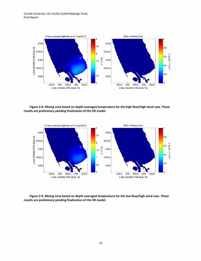
as Figures 2-5 to 2-13.
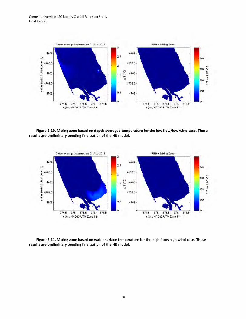
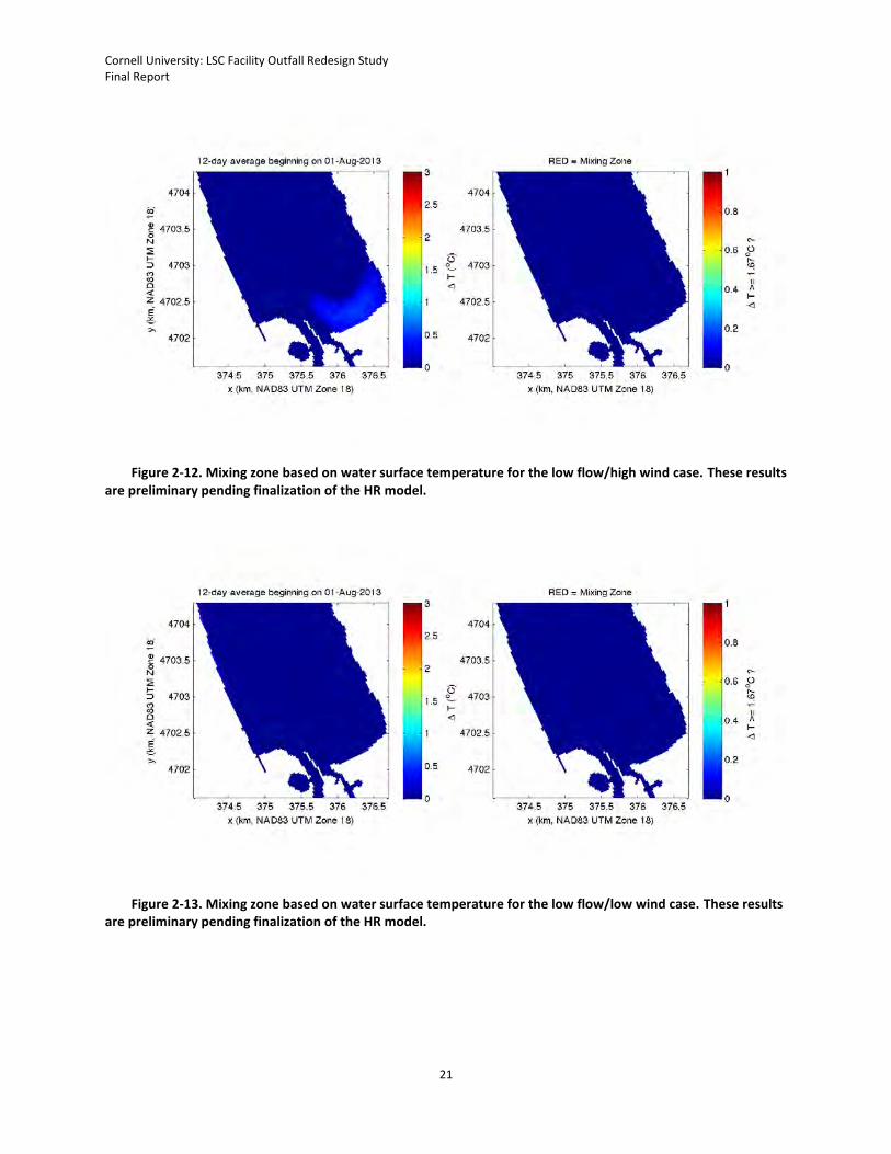
For all test cases, the mixing zone of the LSC outfall as defined by near-bed temperatures is less than
500m in diameter. Using depth-averaged temperature, the mixing zone is a single 25m x 25m square.
Finally, the mixing zone based on surface temperatures is nonexistent.
Figure 2-5. Mixing zone based on temperature in the bottom-most cell for the high flow/high wind case. These results are preliminary pending finalization of the HR model.
Cornell University: LSC Facility Outfall Redesign Study Final Report
18
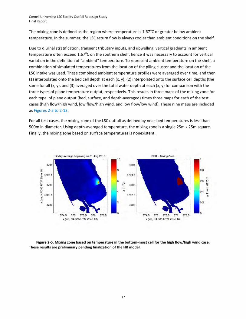
Figure 2-6. Mixing zone based on temperature in the bottom-most cell for the low flow/high wind case. These results are preliminary pending finalization of the HR model.
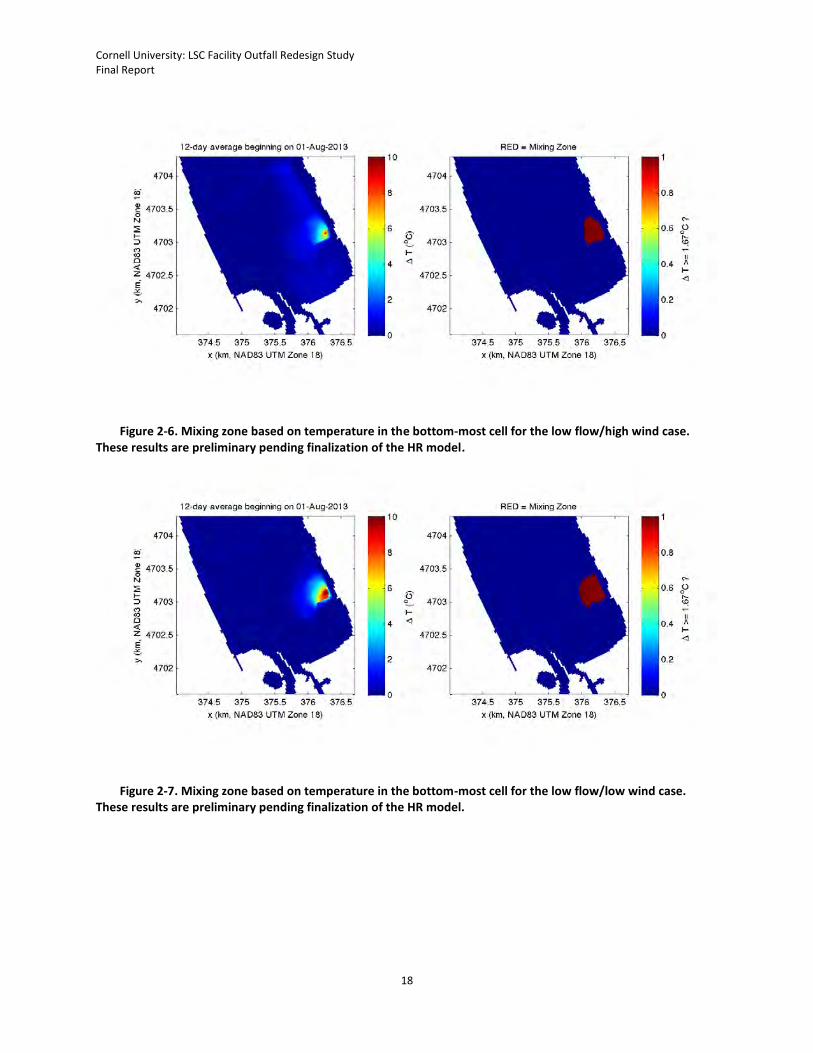
Figure 2-7. Mixing zone based on temperature in the bottom-most cell for the low flow/low wind case. These results are preliminary pending finalization of the HR model.
Cornell University: LSC Facility Outfall Redesign Study Final Report
19
Figure 2-8. Mixing zone based on depth-averaged temperature for the high flow/high wind case. These results are preliminary pending finalization of the HR model.
Figure 2-9. Mixing zone based on depth-averaged temperature for the low flow/high wind case. These results are preliminary pending finalization of the HR model.
Cornell University: LSC Facility Outfall Redesign Study Final Report
20
Figure 2-10. Mixing zone based on depth-averaged temperature for the low flow/low wind case. These results are preliminary pending finalization of the HR model.
Figure 2-11. Mixing zone based on water surface temperature for the high flow/high wind case. These results are preliminary pending finalization of the HR model.
Cornell University: LSC Facility Outfall Redesign Study Final Report
21
Figure 2-12. Mixing zone based on water surface temperature for the low flow/high wind case. These results are preliminary pending finalization of the HR model.
Figure 2-13. Mixing zone based on water surface temperature for the low flow/low wind case. These results are preliminary pending finalization of the HR model.
Cornell University: LSC Facility Outfall Redesign Study Final Report
22
3. Task 2: Identify an Alternative Outfall Location in the Class AA
Segment of Cayuga Lake
3.1. Calculation of Photic Zone Depth The SPDES permit requires Cornell to identify an alternative outfall location within the Class AA segment
of Cayuga Lake (i.e., north of the 303(d) line) where the LSC return flow would remain below the photic
zone. Photic zone is defined as the depth where 1% of the photosynthetically active radiation (PAR)
striking the lake surface remains detectable; this definition is widely used in limnology and
oceanography.
Photic zone depth varies spatially and temporally in the lake, as it is affected by materials dissolved and
suspended in the water column. Consequently, the project team sought to compile all available light
profile data in the Class AA segment of Cayuga Lake for a statistical definition of photic zone. The major
source of light profile data was the LSC monitoring conducted by the Upstate Freshwater Institute (UFI)
on behalf of Cornell; UFI measured the depth of light penetration in regions of Cayuga Lake over a nine
year period (1998-2006). For most years, light profile data were collected biweekly between April and
October. These data were supplemented with additional light profile measurements collected during
2013 to support the Cayuga Lake Modeling Project. As described in the approved project work plan, the
critical photic zone depth is defined as the upper 75% of the pooled observations from the ten years of
light profile measurements collected in the Class AA segment of Cayuga Lake.
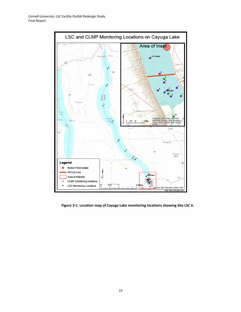
The historical LSC monitoring program included frequent light profile measurements at three locations
within the Class AA segment of Cayuga Lake: sites 6, 8, and LSC (Figure 3-1). Based on a statistical
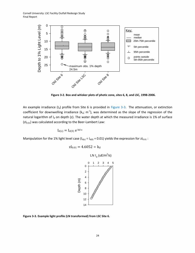
comparison of data from the three sites, there was no significant difference between the sites with
respect to the depth of light penetration (Figure 3-2). Site 6 is located just north of the 303(d) line within
the Class AA segment of Cayuga Lake and in general alignment with the intake pipeline. The project
team used light penetration data from Site 6 to calculate the upper 75% of the ten years of observation.
Cornell University: LSC Facility Outfall Redesign Study Final Report
23
Figure 3-1. Location map of Cayuga Lake monitoring locations showing Site LSC 6.
Cornell University: LSC Facility Outfall Redesign Study Final Report
24
Figure 3-2. Box and whisker plots of photic zone, sites 6, 8, and LSC, 1998-2006.
An example irradiance (Id) profile from Site 6 is provided in Figure 3-3. The attenuation, or extinction
coefficient for downwelling irradiance (kd; m-1), was determined as the slope of the regression of the
natural logarithm of Id on depth (z). The water depth at which the measured irradiance is 1% of surface
(zI0.01) was calculated according to the Beer-Lambert Law:
Id(z) = Id(0) e-kd·z
Manipulation for the 1% light level case (Id(z) ÷ Id(0) = 0.01) yields the expression for zI0.01 :
zI0.01 = 4.6052 ÷ kd
Figure 3-3. Example light profile (LN transformed) from LSC Site 6.
maximum obs. 1% depth24.5m
Old
Site
6
Old
Site
LSC
Old
Site
8
Depth
to 1
% L
ight
Level (m
) 0
5
10
15
20
25
25th-75th percentile
medianmean
points outside5th-95th percentile
5th percentile
95th percentile
Key:
LN Id (uE/m
2/s)
0 1 2 3 4 5
Depth
(m
)
0
2
4
6
8
10
12
14
Cornell University: LSC Facility Outfall Redesign Study Final Report
25
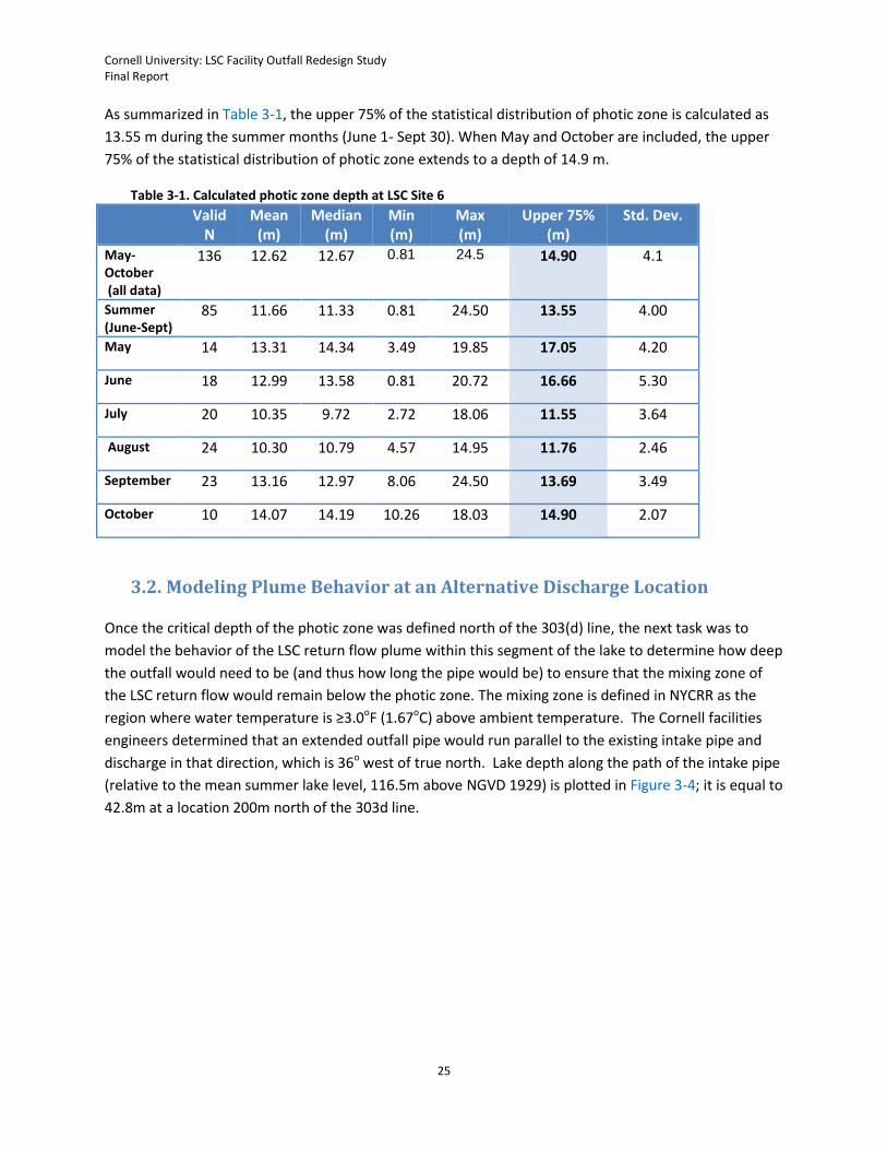
As summarized in Table 3-1, the upper 75% of the statistical distribution of photic zone is calculated as
13.55 m during the summer months (June 1- Sept 30). When May and October are included, the upper
75% of the statistical distribution of photic zone extends to a depth of 14.9 m.
Table 3-1. Calculated photic zone depth at LSC Site 6
Valid N
Mean (m)
Median (m)
Min (m)
Max (m)
Upper 75% (m)
Std. Dev.
May-October (all data)
136 12.62 12.67 0.81 24.5 14.90 4.1
Summer (June-Sept)
85 11.66 11.33 0.81 24.50 13.55 4.00
May 14 13.31 14.34 3.49 19.85 17.05 4.20
June 18 12.99 13.58 0.81 20.72 16.66 5.30
July 20 10.35 9.72 2.72 18.06 11.55 3.64
August 24 10.30 10.79 4.57 14.95 11.76 2.46
September 23 13.16 12.97 8.06 24.50 13.69 3.49
October 10 14.07 14.19 10.26 18.03 14.90 2.07
3.2. Modeling Plume Behavior at an Alternative Discharge Location
Once the critical depth of the photic zone was defined north of the 303(d) line, the next task was to
model the behavior of the LSC return flow plume within this segment of the lake to determine how deep
the outfall would need to be (and thus how long the pipe would be) to ensure that the mixing zone of
the LSC return flow would remain below the photic zone. The mixing zone is defined in NYCRR as the
region where water temperature is ≥3.0oF (1.67oC) above ambient temperature. The Cornell facilities
engineers determined that an extended outfall pipe would run parallel to the existing intake pipe and
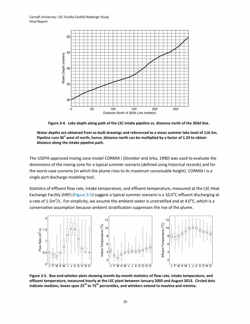
discharge in that direction, which is 36o west of true north. Lake depth along the path of the intake pipe
(relative to the mean summer lake level, 116.5m above NGVD 1929) is plotted in Figure 3-4; it is equal to
42.8m at a location 200m north of the 303d line.
Cornell University: LSC Facility Outfall Redesign Study Final Report
26
Figure 3-4. Lake depth along path of the LSC intake pipeline vs. distance north of the 303d line.
Water depths are obtained from as-built drawings and referenced to a mean summer lake level of 116.5m. Pipeline runs 36
o west of north; hence, distance north can be multiplied by a factor of 1.24 to obtain
distance along the intake pipeline path.
The USEPA-approved mixing zone model CORMIX I (Doneker and Jirka, 1990) was used to evaluate the
dimensions of the mixing zone for a typical summer scenario (defined using historical records) and for
the worst-case scenario (in which the plume rises to its maximum conceivable height). CORMIX I is a
single port discharge modeling tool.
Statistics of effluent flow rate, intake temperature, and effluent temperature, measured at the LSC Heat
Exchange Facility (HXF) (Figure 3-5) suggest a typical summer scenario is a 10.0oC effluent discharging at
a rate of 1.5m3/s. For simplicity, we assume the ambient water is unstratified and at 4.0oC, which is a
conservative assumption because ambient stratification suppresses the rise of the plume.
Figure 3-5. Box-and-whisker plots showing month-by-month statistics of flow rate, intake temperature, and effluent temperature, measured hourly at the LSC plant between January 2005 and August 2013. Circled dots indicate medians, boxes span 25
th to 75
th percentiles, and whiskers extend to maxima and minima.
Cornell University: LSC Facility Outfall Redesign Study Final Report
27
The plume rises to its maximum height when effluent buoyancy is maximized. Maximum effluent
buoyancy occurs when the ambient temperature of the receiving water is 4.0oC (the temperature at
which fresh water is most dense) and the effluent temperature is maximal. The system that supplies
cold water from the LSC heat exchange facility (HXF) to buildings on the Cornell campus is designed for
62oF (16.7oC) return water, and effluent always remains colder than the water returning from campus –
the maximum effluent temperature observed between 2005 and 2013 was 12.8oC. Consequently,
16.7oC effluent discharging into 4.0oC unstratified ambient water is an extremely conservative worst-
case scenario (it actually cannot happen with the current LSC HXF design). Turbulence due to ambient
current and surface wind stress dilutes the effluent plume, so wind and ambient currents are zero in the
worst case. The effect of flow rate on mixing is less straightforward; higher flow rate increases
buoyancy flux, which increases the rate of plume rise, but also increases mixing, which dilutes the plume
as it rises. The research team tested a range of effluent flow rates between 0.5m3/s and 3.0m3/s,
determining that the worst case for the preliminary outfall design is 1.5m3/s (demonstrated in Figure 3-
6). Note that the SPDES permit limits the maximum daily flow of the LSC system to 2.0m3/s.
The proposed specification for the outfall in the workplan was a 57-inch inner-diameter single port pipe
located 1m to 5m above the lake bottom and discharging to the north. Preliminary analysis of pipe
availability and material properties indicates the suitability of 63-inch DR26 HDPE pipe, which has an
inner diameter of 57.9 inches (1.47m). This type of pipe, if run along the path of the intake pipeline to a
location 200m north of the 303(d) line, could be propped 3m above the bed such that the discharge
direction is angled 12o above the horizontal plane.
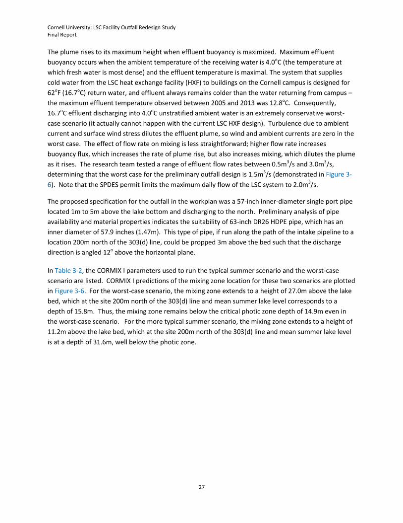
In Table 3-2, the CORMIX I parameters used to run the typical summer scenario and the worst-case
scenario are listed. CORMIX I predictions of the mixing zone location for these two scenarios are plotted
in Figure 3-6. For the worst-case scenario, the mixing zone extends to a height of 27.0m above the lake
bed, which at the site 200m north of the 303(d) line and mean summer lake level corresponds to a
depth of 15.8m. Thus, the mixing zone remains below the critical photic zone depth of 14.9m even in
the worst-case scenario. For the more typical summer scenario, the mixing zone extends to a height of
11.2m above the lake bed, which at the site 200m north of the 303(d) line and mean summer lake level
is at a depth of 31.6m, well below the photic zone.
Cornell University: LSC Facility Outfall Redesign Study Final Report
28
Table 3-2. CORMIX I input parameters for typical summer scenario and worst-case scenario
CORMIX I parameters Typical summer
scenario Worst-case
scenario
Outfall diameter 1.47m 1.47m
Height of outfall above bed 3.0m 3.0m
Vertical discharge angle 12o 12o
Water depth 42.8m 42.8m
Effluent flow rate 1.5m3/s 1.5m3/s
Ambient temperature 4.0oC 4.0oC
Effluent temperature 10.0oC 16.7oC
Figure 3-6. Outer contours of mixing zone for worst-case scenario and for typical summer scenario, predicted by CORMIX I. Input parameters are given in Table 3-2. Outer contour of mixing zone is defined as 1.67
oC above
ambient temperature.
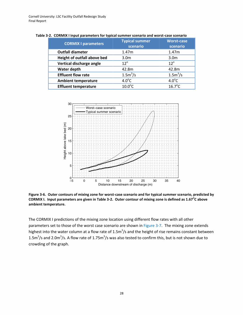
The CORMIX I predictions of the mixing zone location using different flow rates with all other
parameters set to those of the worst case scenario are shown in Figure 3-7. The mixing zone extends
highest into the water column at a flow rate of 1.5m3/s and the height of rise remains constant between
1.5m3/s and 2.0m3/s. A flow rate of 1.75m3/s was also tested to confirm this, but is not shown due to
crowding of the graph.
Cornell University: LSC Facility Outfall Redesign Study Final Report
29
Figure 3-7. Outer contours of mixing zone predicted by CORMIX I for worst-case scenario with modified discharge rate. Discharge rates are printed on the contours. Outer contour of mixing zone is defined as 1.67
oC
above ambient temperature.

Cornell University: LSC Facility Outfall Redesign Study Final Report
30
4. Task 3: Conceptual Design of the Outfall Extension
4.1. Overview Cornell has developed a conceptual design for a future outfall extension to a location 200m north of the
303(d) line along the pathway of the intake pipeline. As summarized in Section 3, the mixing zone of the
LSC return flow would not extend far enough upward in the water column to reach the photic zone at
this location. This conceptual design was prepared to comply with the LSC facility’s 2013 SPDES permit
condition and does not imply that the University considers this outfall extension to have any positive
impacts on Cayuga Lake water quality, local air quality, local and regional energy management, or
greenhouse gas emissions.
Overall, extending the LSC facility outfall would likely cost $13 to $14M and require about 7 years from
initial planning to completion. This timetable assumes a reasonably smooth process for environmental
review, local approvals, and regulatory approvals. Because local experience suggests that approvals for
projects of this type nearly always require more effort and expense than planned, a total of 12 months
of contingency time was included to account for this typical experience. Similarly, the cost estimates
included an allowance for some reasonable unforeseen additional work in local approvals or permitting,
but may be insufficient if the project’s SEQRA review, permitting, easement, or other processes require
excessive time or effort.
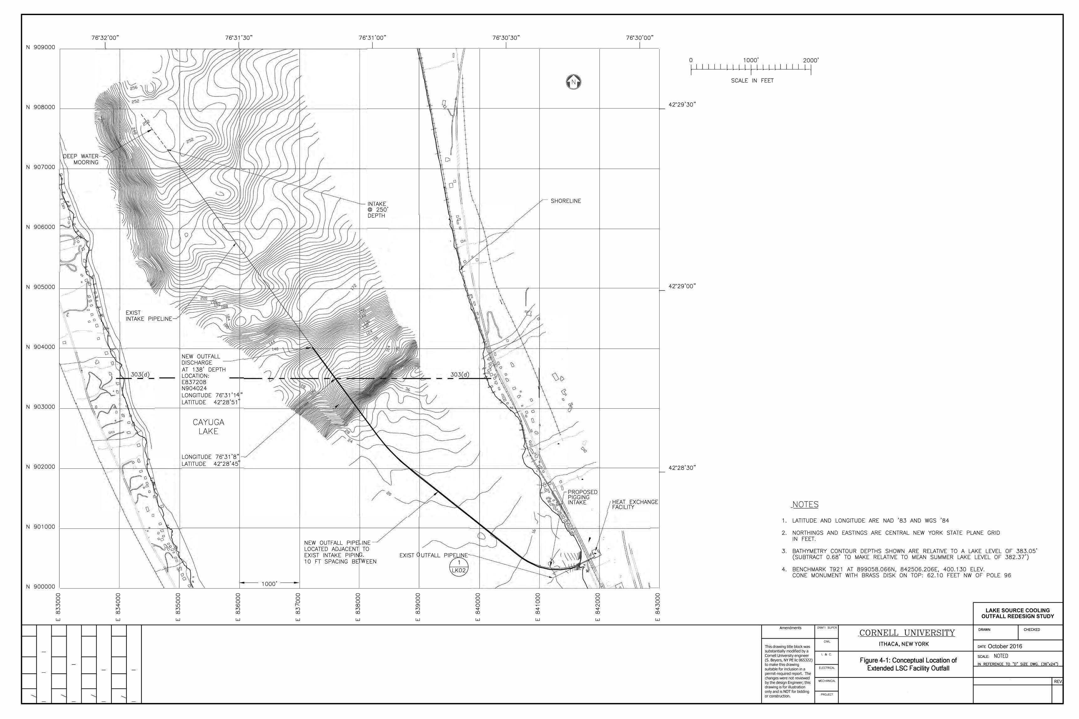
4.2. Basis of Conceptual Design The outfall would be extended to a location 656 feet (200m) beyond the currently-defined 303(d) line in
Cayuga Lake. The outfall pipe would consist of a single new 63-inch high density polyethylene (HDPE)
pipe extending from a flange in the existing outfall, located approximately 341 feet from the wet well of
the LSC Heat Exchange Facility (HEF). The new 63-inch HDPE pipe would extend approximately 5,900
feet generally paralleling the LSC intake pipe. The conceptual layout of an extended outfall is shown in
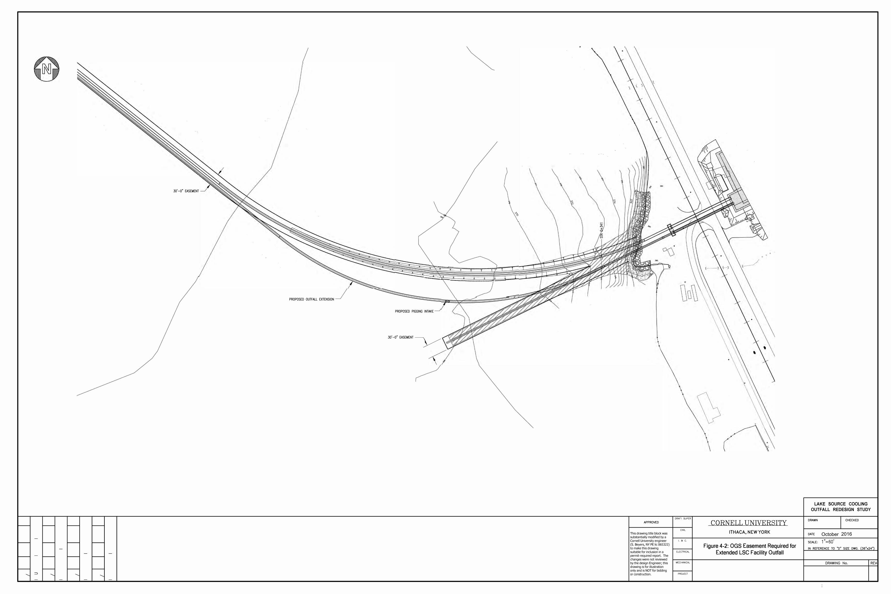
in Figure 4-1. In Figure 4-2, the additional easement required from New York State’s Office of General
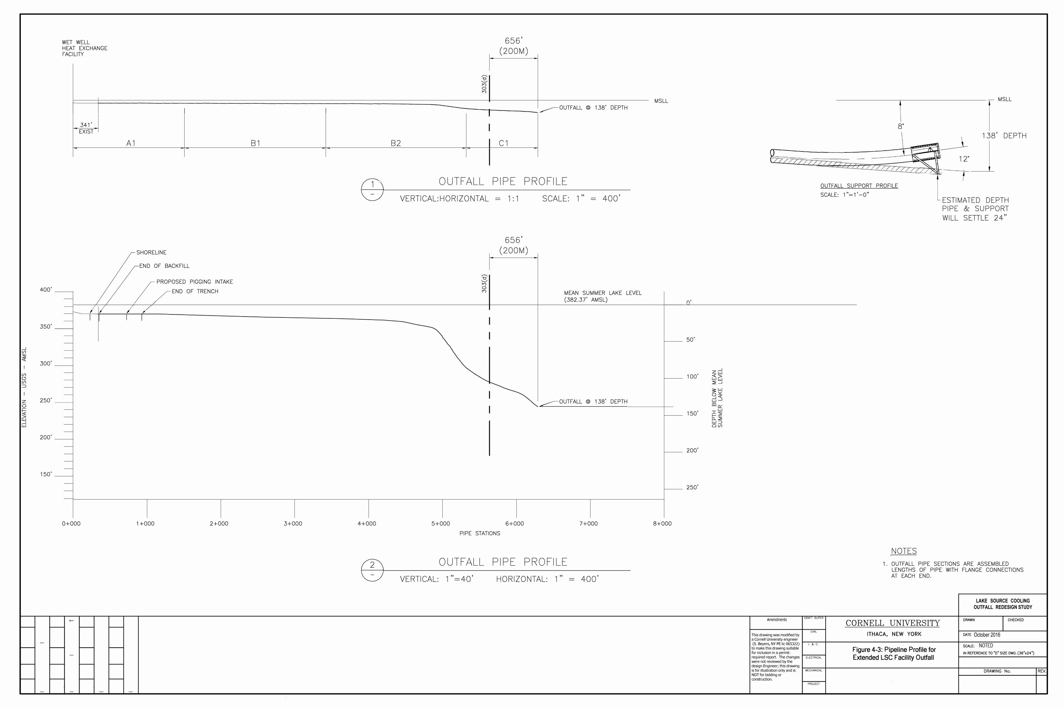
Services (OGS) for an extended outfall is displayed. The profile of the extended outfall is shown in Figure
4-3.
The conceptual design estimate also includes the installation of one (1) new chilled water pump and two
(2) new heat exchangers at the HEF, and a new outfall diffuser. The new pump and heat exchangers
were included to maintain operating capacity despite the greater head losses that would result from this
extended outfall configuration, which would also increase energy use (and associated environmental
impacts) for the life of the facility. The schematic design anticipates an open-ended pipe resting on a
cradle constructed from steel beams; it is assumed that no diffuser would be required, as supported by
the modeling. However, due to uncertainty in future regulatory requirements or interpretations, this
cost estimate also includes a diffuser.
In determining scope and costs, it was assumed that the overall scope of an outfall extension would
include the following:
SEQR Review (coordinated among Involved Agencies)
Cornell University: LSC Facility Outfall Redesign Study Final Report
31
Joint permit for protection of waters for dredging (NYSDEC, ACOE)
Water quality certification for construction in water (NYSDEC, ACOE)
Dredging/spoil disposal plan
Bathymetric survey
Easement application and review (NYSOGS)
Local permits (City of Ithaca Site Plan Approval)
Pipeline design (Preliminary, Design Development, Final, and Contract Documents)
Deployment plan
Equipment and Materials procurement
Bidding and Award
Construction/ Construction Management
Commissioning and Testing
4.3. Conceptual Cost Estimates With support from a consulting engineering firm, Cornell developed a conceptual-level estimate of
overall project cost which includes planning, design, management, survey, permitting, and construction.
This cost estimate was based on the conceptual design. Should a new outfall be justified and required,
both the design and the cost estimate would be reassessed and, as needed, optimized before
implementation. This design could also be optimized during subsequent design phases. Examples of
design changes include such refinements as changing the pipe size to reduce head losses, if warranted
by energy payback, or altering the outfall location to accommodate subsurface conditions.
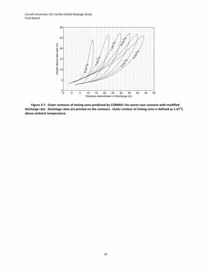
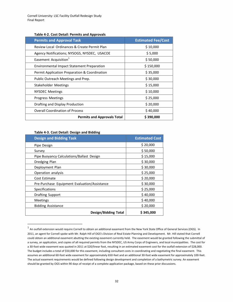
A planning-level estimate of the cost for an outfall extension is summarized in Table 4-1. Additional
breakdown of the costs for the major project components are detailed in Tables 4-2, 4-3, and 4-4. This
cost estimate represents labor and materials required to complete the permitting, design, survey,
bidding, and construction phases. The total project budget estimate is approximately $13.4M.
Table 4-1. Conceptual Cost Estimate of Outfall Extension
Task or Cost Element Total Cost
Permits and Approvals – See Table 4-2 for detail $ 390,000
Design and Bidding – See Table 4-3 for detail $ 345,000
Construction – See Table 4-4 for detail $ 8,388,000
Sub-Total for Project $ 9,123,000
Contingency (25%) $ 2,280,750
Project Management & Administrative Overhead $ 2,000,000
Total Estimated Cost (rounded) $13,400,000
$ 7,900,000
Cornell University: LSC Facility Outfall Redesign Study Final Report
32
Table 4-2. Cost Detail: Permits and Approvals
Permits and Approval Task Estimated Fee/Cost
Review Local Ordinances & Create Permit Plan $ 10,000
Agency Notifications; NYSOGS, NYSDEC, USACOE $ 5,000
Easement Acquisition1 $ 50,000
Environmental Impact Statement Preparation $ 150,000
Permit Application Preparation & Coordination $ 35,000
Public Outreach Meetings and Prep. $ 30,000
Stakeholder Meetings $ 15,000
NYSDEC Meetings $ 10,000
Progress Meetings $ 25,000
Drafting and Display Production $ 20,000
Overall Coordination of Process $ 40,000
Permits and Approvals Total $ 390,000
Table 4-3. Cost Detail: Design and Bidding
Design and Bidding Task Estimated Cost
Pipe Design $ 20,000
Survey $ 50,000
Pipe Buoyancy Calculations/Ballast Design $ 15,000
Dredging Plan $ 30,000
Deployment Plan $ 30,000
Operation analysis $ 25,000
Cost Estimate $ 20,000
Pre-Purchase Equipment Evaluation/Assistance $ 30,000
Specifications $ 25,000
Drafting Support $ 40,000
Meetings $ 40,000
Bidding Assistance $ 20,000
Design/Bidding Total $ 345,000
1 An outfall extension would require Cornell to obtain an additional easement from the New York State Office of General Services (OGS). In
2011, an agent for Cornell spoke with Mr. Ralph Hill of OGS’s Division of Real Estate Planning and Development. Mr. Hill stated that Cornell
could obtain an additional easement abutting the existing easement currently held. The easement would be granted following the submittal of
a survey, an application, and copies of all required permits from the NYSDEC, US Army Corps of Engineers, and local municipalities. The cost for
a 30-foot wide easement was quoted in 2011 at $20/linear foot, resulting in an estimated easement cost for the outfall extension of $28,000.
The budget includes a total of $50,000 for this easement, including consultant costs in coordinating and negotiating the final easement. This
assumes an additional 60-foot wide easement for approximately 650-feet and an additional 30-foot wide easement for approximately 100-feet.
The actual easement requirements would be defined following design development and completion of a bathymetric survey. An easement
should be granted by OGS within 90 days of receipt of a complete application package, based on these prior discussions.
Cornell University: LSC Facility Outfall Redesign Study Final Report
33
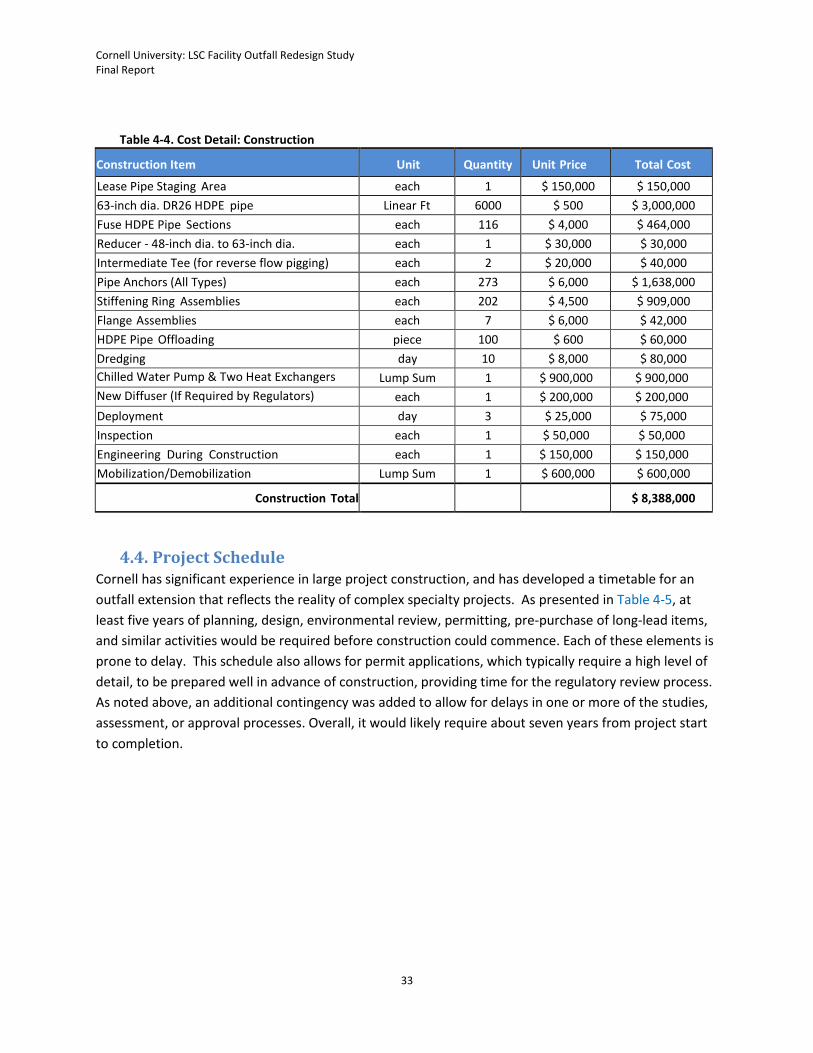
Table 4-4. Cost Detail: Construction
Construction Item Unit Quantity Unit Price Total Cost
Lease Pipe Staging Area each 1 $ 150,000 $ 150,000
63-inch dia. DR26 HDPE pipe Linear Ft 6000 $ 500 $ 3,000,000
Fuse HDPE Pipe Sections each 116 $ 4,000 $ 464,000
Reducer - 48-inch dia. to 63-inch dia. each 1 $ 30,000 $ 30,000
Intermediate Tee (for reverse flow pigging) each 2 $ 20,000 $ 40,000
Pipe Anchors (All Types) each 273 $ 6,000 $ 1,638,000
Stiffening Ring Assemblies each 202 $ 4,500 $ 909,000
Flange Assemblies each 7 $ 6,000 $ 42,000
HDPE Pipe Offloading piece 100 $ 600 $ 60,000
Dredging day 10 $ 8,000 $ 80,000
Chilled Water Pump & Two Heat Exchangers
(Option) Outfall Diffuser
Lump Sum 1 $ 900,000 $ 900,000
New Diffuser (If Required by Regulators)
(Option) Outfall Diffuser
each 1 $ 200,000 $ 200,000
Deployment day 3 $ 25,000 $ 75,000
Inspection each 1 $ 50,000 $ 50,000
Engineering During Construction each 1 $ 150,000 $ 150,000
Mobilization/Demobilization Lump Sum 1 $ 600,000 $ 600,000
Construction Total $ 8,388,000
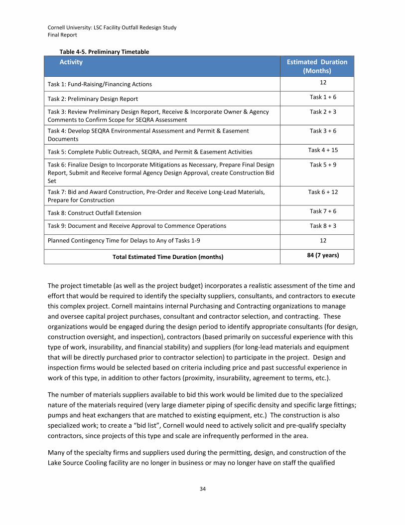
4.4. Project Schedule Cornell has significant experience in large project construction, and has developed a timetable for an
outfall extension that reflects the reality of complex specialty projects. As presented in Table 4-5, at
least five years of planning, design, environmental review, permitting, pre-purchase of long-lead items,
and similar activities would be required before construction could commence. Each of these elements is
prone to delay. This schedule also allows for permit applications, which typically require a high level of
detail, to be prepared well in advance of construction, providing time for the regulatory review process.
As noted above, an additional contingency was added to allow for delays in one or more of the studies,
assessment, or approval processes. Overall, it would likely require about seven years from project start
to completion.
Cornell University: LSC Facility Outfall Redesign Study Final Report
34
Table 4-5. Preliminary Timetable
Activity Estimated Duration (Months)
Task 1: Fund-Raising/Financing Actions 12
Task 2: Preliminary Design Report Task 1 + 6
Task 3: Review Preliminary Design Report, Receive & Incorporate Owner & Agency Comments to Confirm Scope for SEQRA Assessment
Task 2 + 3
Task 4: Develop SEQRA Environmental Assessment and Permit & Easement Documents
Task 3 + 6
Task 5: Complete Public Outreach, SEQRA, and Permit & Easement Activities Task 4 + 15
Task 6: Finalize Design to Incorporate Mitigations as Necessary, Prepare Final Design Report, Submit and Receive formal Agency Design Approval, create Construction Bid Set
Task 5 + 9
Task 7: Bid and Award Construction, Pre-Order and Receive Long-Lead Materials, Prepare for Construction
Task 6 + 12
Task 8: Construct Outfall Extension Task 7 + 6
Task 9: Document and Receive Approval to Commence Operations Task 8 + 3
Planned Contingency Time for Delays to Any of Tasks 1-9 12
Total Estimated Time Duration (months) 84 (7 years)
The project timetable (as well as the project budget) incorporates a realistic assessment of the time and
effort that would be required to identify the specialty suppliers, consultants, and contractors to execute
this complex project. Cornell maintains internal Purchasing and Contracting organizations to manage
and oversee capital project purchases, consultant and contractor selection, and contracting. These
organizations would be engaged during the design period to identify appropriate consultants (for design,
construction oversight, and inspection), contractors (based primarily on successful experience with this
type of work, insurability, and financial stability) and suppliers (for long-lead materials and equipment
that will be directly purchased prior to contractor selection) to participate in the project. Design and
inspection firms would be selected based on criteria including price and past successful experience in
work of this type, in addition to other factors (proximity, insurability, agreement to terms, etc.).
The number of materials suppliers available to bid this work would be limited due to the specialized
nature of the materials required (very large diameter piping of specific density and specific large fittings;
pumps and heat exchangers that are matched to existing equipment, etc.) The construction is also
specialized work; to create a “bid list”, Cornell would need to actively solicit and pre-qualify specialty
contractors, since projects of this type and scale are infrequently performed in the area.
Many of the specialty firms and suppliers used during the permitting, design, and construction of the
Lake Source Cooling facility are no longer in business or may no longer have on staff the qualified

Cornell University: LSC Facility Outfall Redesign Study Final Report
35
individuals used for that work (or others with equivalent skills and experience). Therefore, as the
preliminary design is completed and enough information is available to begin selecting qualified
suppliers, consultants, and contractors, a significant effort would be required to develop a suitable
proposal list (for consultants) and bidders’ lists (for materials and contracting). These efforts are
incorporated into the schedules and cost estimates presented.
N 909000
N 908000
N 907000
N 906000
N 905000
N 904000
N 903000
N 902000
N 901000
N 900000 0 0 0 n n co
w
75·32·00"
EEP WATER MOORING
0
"'0
a
0 0 0
0
D
0 0 0 'SI-n co
w
EXIST INTAKE PIPELINE
D
0 oo
�oo
0 0 0 L() n co
w
75·31 '30"
NEW OUTFALL DISCHARGE AT 138' DEPTH LOCATION: E837208 N904024 LONGITUDE 76"31'1 " LATITUDE 42"28'51
CAYUGA
LAKE
LONGITUDE 76"31 '8" LATITUDE 42"28'45
(l 0
0
0 0 0 CD n co
w
1 ooo·
0 0 0
n co
w
75·31 ·oo"
INTAKE @ 250' DEPTH
NEW OUTFALL PIPE INE LOCATED ADJACENT TO EXIST INTAKE PIPIN 10 FT SPACING BE EEN
0 0 0 co n co
w
D ·.·.
D
,,,,,,
,, ,, ,,
,,
0
EXIST UTFALL PIPELINE
... 0
\
0 0 0 (J) n co
w
75·30'30"
D
\
<7
0 0 0 0 'SI-co
w
\
0 0 0 � 'SI-co
w
0
SHORELINE
•
PROPOSED PIGGING INTAKE
0 0 0 N 'SI-co
w
75· 30'00"
HEAT EXCHANGE FACILITY
0 0 0 n 'SI-co
w
0
I
42"29'30"
42"29'00"
42"28'30"
1000' I I I I I I I I I
SCALE IN FEET
2000' I I
NOTES
1. LATITUDE AND LONGITUDE ARE NAD '83 AND WGS '84
2. NORTHINGS AND EASTINGS ARE CENTRAL NEW YORK STATE PLANE GRIDIN FEET.
3. BATHYMETRY CONTOUR DEPTHS SHOWN ARE RELATIVE TO A LAKE LEVEL OF 383.05'(SUBTRACT 0.68' TO MAKE RELATIVE TO MEAN SUMMER LAKE LEVEL OF 382.37')
4. BENCHMARK T921 AT 899058.066N, 842506.206E, 400.130 ELEV.CONE MONUMENT WITH BRASS DISK ON TOP: 62.1 0 FEET NW OF POLE 96
Amendments DRAFT SUPER
CIVIL
I. & C.
CORNELL UNIVERSITY
LAKE SOURCE COOLING OUTFALL REDESIGN STUDY
DRAWN CHECKED
ITHACA, NEW YORK DATE October 2016SCALE: NOTED IN REFERENCE TO "D" SIZE DWG. (36"x24")
ELECTRICAL
MECHANICAL
PROJECT
REV.
This drawing title block was substantially modified by a Cornell University engineer (S. Beyers, NY PE lic 065322) to make this drawing suitable for inclusion in a permit-required report. The changes were not reviewed by the design Engineer; this drawing is for illustration only and is NOT for bidding or construction.
Figure 4-1: Conceptual Location of Extended LSC Facility Outfall
30' -0" EASEMENT
� 0
----... -
-----·- ---·-----·-... ·----·-··--- ·------
PROPOSED OL/TFALL EXTENSION
PROPOSED PIGGING INTAKE
30'-0" EASEMENT
)/
APPROVED DRAFT SUPER
CIVIL
I. & C.
ELECTRICAL
MECHANICAL
PROJECT
LAKE SOURCE COOLING OUTFALL REDESIGN STUDY
DRAWN
DATE October 20161 "--60' SCALE:
CHECKED
IN REFERENCE TO "D" SIZE DWG. (36"x24")
DRAWING No. REV
This drawing title block was substantially modified by a Cornell University engineer (S. Beyers, NY PE lic 065322) to make this drawing suitable for inclusion in a permit-required report. The changes were not reviewed by the design Engineer; this drawing is for illustration only and is NOT for bidding or construction.
CORNELL UNIVERSITY
ITHACA, NEW YORK
Figure 4-2: OGS Easement Required for Extended LSC Facility Outfall
_J Cf)
<(
I
Cf) Cl Cf)
I
z
w _Jw
WET WELL HEAT EXCHANGE FACILITY
656'
(200M)
r--
r---------
�-----------------
,-------------------
--.---
--��OUTFALL @ 138' DEPTH
I
400' -
-
-
350' -
-
-
-
300' -
-
-
-
250' -
-
-
-
200· -
-
-
-
150' -
-
341' EXIST
I/
0+000
A1
SHORELINE
END OF BACKFILL
/
PROPOSED PIGGING INTAKE
/ END OF TRENCH
I / I I
1 +000 2+000
B1
CD
3+000 4+000
CD
I
B2 C1
OUTFALL PIPE PROFILE
VERTICAL:HORIZONTAL = 1: 1
5+000
656'
(200M)
6+000 PIPE STATIONS
SCALE: 1" = 400'
MEAN SUMMER LAKE LEVEL (382.37' AMSL)
�OUTFALL @ 138' DEPTH
7+000
OUTFALL PIPE PROFILE
VERTICAL: 1 "=40' HORIZONTAL: 1" = 400'
MSLL
8+000
- MSLL
s·
\ n1:------------------t4'�=:11�"�------1-
138' DEPTH
n'
50'
z_J
1 oo· tS �
150'
200·
250'
:::,:_J
:§; w0� _J :5 w rn D:'.
:r: w1---2 o_:::,: w:::) 0 Cf)
Amendments
� 12·
/////////////�
OUTFALL SUPPORT PROFILE SCALE: 1"=1'-0"
NOTES
f
- ESTIMATED DEPTH
PIPE & SUPPORT
WILL SETILE 24"
1. OUTFALL PIPE SECTIONS ARE ASSEMBLEDLENGTHS OF PIPE WITH FLANGE CONNECTIONSAT EACH END.
LAKE SOURCE COOLING OUTFALL REDESIGN STUDY
DRAFT SUPER DRAWN CHECKED
CIVIL
I. & C.
DATE October 2016
SCALE, NOTED
IN REFERENCE TO "D" SIZE DWG. (36"x24") ELECTRICAL
CORNELL UNIVERSITY
ITHACA, NEW YORK
Figure 4-3: Pipeline Profile for Extended LSC Facility Outfall
MECHANICAL
PROJECT
DRAWING No . REV.
This drawing was modified by a Cornell University engineer (S. Beyers, NY PE lic 065322) to make this drawing suitable for inclusion in a permit-required report. The changes were not reviewed by the design Engineer; this drawing is for illustration only and is NOT for bidding or construction.
Cornell University: LSC Facility Outfall Redesign Study Final Report
36
5. Task 4: Environmental Impact Assessment
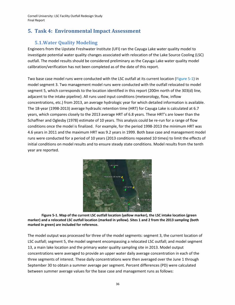
5.1. Water Quality Modeling Engineers from the Upstate Freshwater Institute (UFI) ran the Cayuga Lake water quality model to
investigate potential water quality changes associated with relocation of the Lake Source Cooling (LSC)
outfall. The model results should be considered preliminary as the Cayuga Lake water quality model
calibration/verification has not been completed as of the date of this report.
Two base case model runs were conducted with the LSC outfall at its current location (Figure 5-1) in
model segment 3. Two management model runs were conducted with the outfall relocated to model
segment 5, which corresponds to the location identified in this report {200m north of the 303(d) line,
adjacent to the intake pipeline}. All runs used input conditions (meteorology, flow, inflow
concentrations, etc.) from 2013, an average hydrologic year for which detailed information is available.
The 18-year (1998-2013) average hydraulic retention time (HRT) for Cayuga Lake is calculated at 6.7
years, which compares closely to the 2013 average HRT of 6.8 years. These HRT’s are lower than the
Schaffner and Oglesby (1978) estimate of 10 years. This analysis could be re-run for a range of flow
conditions once the model is finalized. For example, for the period 1998-2013 the minimum HRT was
4.6 years in 2011 and the maximum HRT was 9.2 years in 1999. Both base case and management model
runs were conducted for a period of 10 years (2013 conditions repeated 10 times) to limit the effects of
initial conditions on model results and to ensure steady state conditions. Model results from the tenth
year are reported.
Figure 5-1. Map of the current LSC outfall location (yellow marker), the LSC intake location (green
marker) and a relocated LSC outfall location (marked in yellow). Sites 1 and 2 from the 2013 sampling (both marked in green) are included for reference.
The model output was processed for three of the model segments: segment 3, the current location of
LSC outfall; segment 5, the model segment encompassing a relocated LSC outfall; and model segment
13, a main lake location and the primary water quality sampling site in 2013. Model output
concentrations were averaged to provide an upper water daily average concentration in each of the
three segments of interest. These daily concentrations were then averaged over the June 1 through
September 30 to obtain a summer average per segment. Percent differences (PD) were calculated
between summer average values for the base case and management runs as follows:
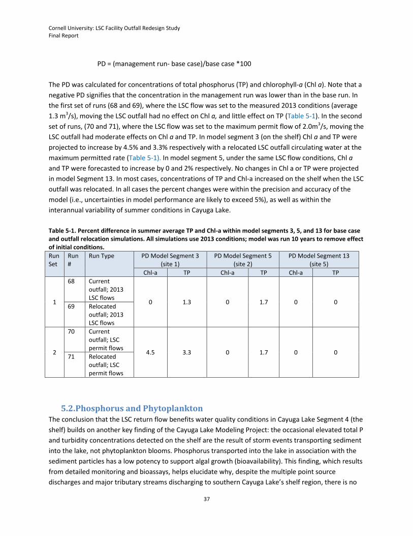
Cornell University: LSC Facility Outfall Redesign Study Final Report
37
PD = (management run- base case)/base case *100
The PD was calculated for concentrations of total phosphorus (TP) and chlorophyll-a (Chl a). Note that a
negative PD signifies that the concentration in the management run was lower than in the base run. In
the first set of runs (68 and 69), where the LSC flow was set to the measured 2013 conditions (average
1.3 m3/s), moving the LSC outfall had no effect on Chl a, and little effect on TP (Table 5-1). In the second
set of runs, (70 and 71), where the LSC flow was set to the maximum permit flow of 2.0m3/s, moving the
LSC outfall had moderate effects on Chl a and TP. In model segment 3 (on the shelf) Chl a and TP were
projected to increase by 4.5% and 3.3% respectively with a relocated LSC outfall circulating water at the
maximum permitted rate (Table 5-1). In model segment 5, under the same LSC flow conditions, Chl a
and TP were forecasted to increase by 0 and 2% respectively. No changes in Chl a or TP were projected
in model Segment 13. In most cases, concentrations of TP and Chl-a increased on the shelf when the LSC
outfall was relocated. In all cases the percent changes were within the precision and accuracy of the
model (i.e., uncertainties in model performance are likely to exceed 5%), as well as within the
interannual variability of summer conditions in Cayuga Lake.
Table 5-1. Percent difference in summer average TP and Chl-a within model segments 3, 5, and 13 for base case and outfall relocation simulations. All simulations use 2013 conditions; model was run 10 years to remove effect of initial conditions.
Run Set
Run #
Run Type PD Model Segment 3 (site 1)
PD Model Segment 5 (site 2)
PD Model Segment 13 (site 5)
Chl-a TP Chl-a TP Chl-a TP
1
68 Current outfall; 2013 LSC flows
0 1.3 0 1.7 0 0 69 Relocated
outfall; 2013 LSC flows
2
70 Current outfall; LSC permit flows
4.5 3.3 0 1.7 0 0 71 Relocated
outfall; LSC permit flows
5.2. Phosphorus and Phytoplankton The conclusion that the LSC return flow benefits water quality conditions in Cayuga Lake Segment 4 (the
shelf) builds on another key finding of the Cayuga Lake Modeling Project: the occasional elevated total P
and turbidity concentrations detected on the shelf are the result of storm events transporting sediment
into the lake, not phytoplankton blooms. Phosphorus transported into the lake in association with the
sediment particles has a low potency to support algal growth (bioavailability). This finding, which results
from detailed monitoring and bioassays, helps elucidate why, despite the multiple point source
discharges and major tributary streams discharging to southern Cayuga Lake’s shelf region, there is no

Cornell University: LSC Facility Outfall Redesign Study Final Report
38
gradient in chlorophyll-a, an indicator of phytoplankton abundance, between the shelf and the main
lake. Thus, a justification NYSDEC cited for requiring the Outfall Redesign Study—that doing so could
reduce phosphorus and phytoplankton levels in Segment 4—has been demonstrated to be unfounded.
Relocation of the outfall would not reduce phosphorus or silt/sediment levels in Segment 4; as
previously noted, modeling indicates that removing the LSC return flow from the shelf would slightly
increase the summer average concentrations of total phosphorus and chlorophyll in this impaired
region. Note that the magnitude of estimated changes in water quality conditions would vary from year
to year in response to meteorological conditions. However, the models project that a relocated outfall
would offer no sustained reduction in Cayuga Lake’s phytoplankton, either on or off the shelf.
5.3. Hydrodynamics NYSDEC ‘s suggestion that relocating the LSC facility outfall within Cayuga Lake might provide the
University with an alternative means to comply with a phosphorus limit on the LSC return flow as
allocated through a TMDL analysis was predicated on an assumption that Segment 4 functions as a
separate water body. The findings of the detailed hydrodynamic modeling undermine this justification
as well. The hydrodynamic models clearly demonstrate that Cayuga Lake behaves as a single water
body. Wind-driven currents, tributary inflows and internal waves circulate water among the depth strata
and regulatory-defined segments.
The recent (2016) decision by NYSDEC to develop a phosphorus TMDL allocation for the entire lake, not
solely the shelf region as was their stated intent in 2012, is consistent with the conclusion that Segment
4 cannot be managed in isolation from the rest of Cayuga Lake. The LSC system draws water in through
an intake and, after the addition of heat only, returns the lake water to the same water body from which
it was withdrawn. Again, it is relevant to cite that circulation of Cayuga Lake water through the LSC
facility adds no phosphorus derived from outside sources.
5.4. Construction and Operations-Related Environmental Factors In addition to potentially increasing the parameters for which the southern shelf is considered impaired,
there are other adverse environmental impacts of an extended outfall. In-lake construction would
disturb sediments and the benthic community as well as temporarily restrict recreational access. The
manufacture, shipping, and assembly of the materials needed to extend the outfall represent additional
environmental impacts. Over the long term, an extended outfall would result in higher pumping heads
and more energy use, for which there are adverse environmental impacts. Increased energy use with no
offsetting benefit is in direct opposition to the University’s goals for carbon neutrality as well as New
York State and federal commitments to climate action.
5.5. Institutional Factors There are institutional consequences as well. An outfall extension would represent a significant
economic burden for Cornell, a not-for-profit institution of higher education that includes State-
supported colleges. The University is committed to investing in environmental projects that provide an
ecosystem benefit, not increase the risk of harm to air quality, water quality, or climate. The review and

Cornell University: LSC Facility Outfall Redesign Study Final Report
39
approval process to extend the outfall would require a significant diversion of resources by the
regulatory community, including local and regional officials of at least four separate agencies.
6. Conclusions
Based on the modeling and analysis completed to date, an outfall extension would not provide any
environmental benefit to Cayuga Lake. Rather, the permit-required modeling demonstrates that
circulation of Cayuga Lake water through the heat exchange facility has a beneficial water quality impact
on the “shelf” (Cayuga Lake Segment 4) by reducing ambient concentrations of total phosphorus and
particles in the water column. The return flow of cool, clear water low in phosphorus from the LSC heat
exchange facility reduces the residence time of water on the shelf, thus diminishing the risk of algal
blooms and diluting influent silts and sediment from the tributaries. Moving the LSC outfall off the shelf
would likely increase the summer average levels of total phosphorus and chlorophyll-a as well as
silt/sediment in Segment 4, thus exacerbating rather than mitigating its regulatory impairment.
There is no environmental benefit to offset the adverse impacts of increased energy consumption. Such
an action would go against University goals for stewardship, NYSDEC’s commitment to reducing
greenhouse gas emissions, and national policy related to climate change. The current operation provides
a net water quality benefit to southern Cayuga Lake and enables the University to advance toward
carbon neutrality. For these reasons, Cornell concludes that an outfall extension is counter indicated as
a means to ensure that the LSC facility does not contribute to an impairment of Cayuga Lake.
Cornell University: LSC Facility Outfall Redesign Study Final Report
40
7. References
Acosta, M.; Anguita, M.; Fernández-Baldomero, F. J.; Ramón, C. L.; Schladow, S. G.; and Rueda, F. J.
(2015). Evaluation of a nested-grid implementation for 3D finite-difference semi-implicit hydrodynamic
models. Environmental Modelling & Software, 64, 241-262.
Akar, P.J.; Jirka, G. H. (1991). CORMIXII: An expert system for hydrodynamic mixing zone analysis of
conventional and toxic multiport diffuser discharges. Technical report, United States Environmental
Protection Agency, EPA/600/3-91/073.
Amorocho, J., and J. J. DeVries. "A new evaluation of the wind stress coefficient over water
surfaces." Journal of Geophysical Research: Oceans. 85.C1 (1980): 433-442.
Chapra, Steven C. Surface water-quality modeling. Waveland press, 2008.
Doneker, R.L.; Jirka, G.H. (1990). Expert system for hydrodynamic mixing zone analysis of conventional
and toxic submerged single port discharges (CORMIX I). Technical report, United States Environmental
Protection Agency. EPA/600/3-90/012.
Gelda, R. K., King, A. T., Effler, S. W., Schweitzer, S. A., & Cowen, E. A. (2015). “Testing and application of
a two-dimensional hydrothermal/transport model for a long, deep, and narrow lake with moderate
Burger number”. Inland Waters, 5(4), 387-402.
Gill, A.E. (1982). Atmosphere-Ocean Dynamics. San Diego: Academic.
Haith, D.A.; Hollingshead, N.; Bell, M.L.; Kreszewski, S.W.; Morey, S.J. (2012). “Nutrient loads to Cayuga
Lake, New York: Watershed modeling on a budget”. J. Water Res. Plann. and Manage., 138, 571-580.
Hilton, A.B.C.; McGillivary, D.L.; Adams, E.E. (1998). “Residence time of freshwater in Boston’s inner
harbor”. J. Water Port Coast. Ocean Eng., 124, 82-89.
Kantha, L.H.; Clayson, C.A. (1994). “An improved mixed layer model for geophysical applications”. J
Geophys Res, 99 (C12), 25235-25266, doi:10.1029/94JC02257.
Lee, J. H., & Jirka, G. H. (1980). Multiport diffuser as line source of momentum in shallow water. Water
Resources Research, 16(4), 695-708.
Martin J.L., McCutcheon S.C. 1999. Hydrodynamics and transport for water quality modeling. Boca Raton, FL: Lewis Publishers. -794 p.
Monsen, N.E.; Cloern, J.E.; Lucas, L.V.; Monismith, S.G. (2002). “A comment on the use of flushing time,
residence time, and age as transport time scales”. Limnol Oceanogr, 47, 1545-1553.
Rueda, F.J. (2001). “A three-dimensional hydrodynamic and transport model for lake environments.”
Ph.D. Dissertation, University of California, Davis.
Cornell University: LSC Facility Outfall Redesign Study Final Report
41
Schaffner, W. and Oglesby R.T. (1978). “Phosphorus loading to lakes and some of their consequences.
Limnol. Oceanogr, 23(1):135-145.
Schweitzer, S. (2015). “Physical Processes in a Long Narrow Deep Lake.” Doctoral dissertation, Cornell
University. Ithaca, NY.
Singleton, V.L.; Rueda, F.J.; Little, J.C. (2010). “A coupled bubble plume-reservoir model for hypolimnetic
oxygenation.” Water Resour Res, 46(W12538), doi:10.1029/2009WR009012.
Smith, P. E. (1997). “A three-dimensional, finite-difference model for estuarine circulation.” Ph.D.
Dissertation, University of California, Davis.
Vandebroek, E. (2011). “Development of boundary conditions and bathymetry data for modeling
transport processes in the southern end of Cayuga Lake.” M.Eng. Report, Cornell University.