
Outdoor Furnaces - Heatmor®
80
Outdoor Furnaces TM SAVE THESE INSTRUCTIONS
Transcript of Outdoor Furnaces - Heatmor®

Outdoor Furnaces
TM
save these instructiOns

ii
When these safety symbols appear on the following pages, they will alert you to the possibility of serious injury if you do not comply with the corresponding instructions. the hazard may originate from something mechanical or electrical shock. Please read the instructions carefully.
When you see this safety symbol on the following pages, it will alert you to the possibility of damage to your heatMOrtM stainless steel Outdoor Furnace if you do not comply with the corresponding instructions. Please read the instructions carefully.
the heatMOrtM Stainless Steel Outdoor Furnace is certified to offer safe service provided it is installed, operated and maintained in accordance with the instructions contained in this manual.
Proper personal protective equipment, (PPe), Must Be WOrn at aLL tiMes when servicing and maintaining any of the heatMOrtM stainless steel Outdoor Furnace product line.

iii
taBLe OF cOntents Page # Dear heatMOr™ OWner 1 nOtice tO the reaDer 2 Phase ii hangtag 3 saFety certiFicatiOn 41 Furnace PhOtO 5 resiDentiaL Furnace sPeciFicatiOns 62 FrOnt cut aWay vieW OF MODeL 200 ssP 7 Furnace Parts List 8 3 rear cut aWay vieW OF MODeL 200 ssP 9 Furnace Parts List 10 4 MiniMuM cLearance seParatiOn sPeciFicatiOns 115 Warnings anD PrecautiOns 12 A Installation 12 B Electrical 13 C Other 136 cOncrete PaD sPeciFicatiOns 14 A Model 200 SSP Pad Specifications 147 instaLLatiOn OF the heatMOr™ Furnace 15 A Equipment Required 15 B Placing the HEATMOR™ on the Concrete Pad 15 C Caulking Around the Firebox Base 15 D Caulking Around the Outside Perimeter of HEATMOR™ 15 E Filling the HEATMOR™ Outdoor Furnace Initially with Water 16 F Maintaining Water in the Bladder and in the HEATMOR™ 17 G Heatmor Recommended Installation Instructions 18-20
8 saFe OPerating guiDeLines 21 A Operation 21 B Lighting Your HEATMOR™ for the First Time 23 C Dew Point 24 D Loading Wood Pellets into the HEATMOR™ 24 E What can I burn? 25 i. Wood Pellets 25 F How does a fire burn out? 25 G Stages of Combustion 25 H Efficiency Measurements and Types of Fires 26 I Handling and Storage of Wood Pellets 26 9 Water 28 A Qualities of Water to Use 28 B Water Level Maintenance 28 C Removal of water and replacement of water 28 D Water Additives 29 E Water Treatment Additives and Safety Specifications 30

iv
F Adding Freeze Protection Products 3110 BLaDDer asseMBLy 32 A Bladder 32 B Bladder Gate Valve and Bladder Hose 3311 Water JacKet 34 A Water Jacket 34 B Supply Line and Return Line Connectors 34 C Relief Vent Pipe and Weighted Pop off Ball 3412 FireBOX anD Other cOMPOnents 35 A Firebox 35 B Firebox Door 36 C Firebox Door Handle 37 D Firebox Door Hinge 37 E Firebox Door Gasket 37 F Firebox Door Frame 3813 air suPPLy 39 A Combustion Air Blower and Flipper Assembly 39 i. Operation of the Combustion Air Blower and Flipper Assembly 39 ii. Steps to Maintain your Blower / Flipper Assembly 39 B Air Box(s) 4014 chiMney anD FLue 41 A Chimney 41 B Chimney Extension(s) 41 C Flue 42 D Flue Covers 42 E Flue Scraper 4215 ashes 43 A Ash Management and Ash Removal 43 B Ash Pan 43 C Ash Pan Cover Plate 4416 eLectricaL 45 A Electrical Supply 45 B Electrical Supply Junction Box 45 C Double Electrical Outlets at rear 46 D Electronic Controller 46 E Electronic Controller Temperature Probe 46 F Watlow Flame Sensor Control 47 G Watlow Flame Sensor Control Temperature Probe 48 H Dayton Auger Speed Control 48 I High Water Temperature Safety Shutoff Control 49 J Front Light and Fan Power Switch 50 K Iginition Switch 51 L In The Event of a Power Failure 51

v
17 PeLLet suPPLy 52 A Internal Hopper of the HEATMOR™ 52 B Auger and Auger Motor 5218 eXteriOr cLaDDing anD insuLatiOn 53 A Outer Front and Side Doors of the HEATMOR™ 53 B Roof of the HEATMOR™ 53 C Sides of the HEATMOR™ 54 D Insulation 5419 air LeaKs 55 A Checking For Air Leaks 5520 Water LeaKs 5621 seasOn start uP & shut DOWn checKLists 57-58 22 FreQuentLy asKeD QuestiOns 59-6023 trOuBLeshOOting anD sOLutiOns 61-71 heatMOr™ stainLess steeL LiMiteD Warranty 73-74 heatMOr™ FOr LiFe 75 neW Furnace DeLivery checK sheet 76 Wiring DiagraMs 77
1
Dear HEATMOR™ Owner,
On behalf of myself and the employees of HEATMOR™, I would like to take this opportunity to personally thank you for the purchase of our HEATMOR™ Stainless Steel Outdoor Furnace. You can be assured that your HEATMOR™ was constructed with great emphasis on quality and workmanship. It is our commitment to provide you with the finest outdoor furnace in the industry. We wish you many years of trouble-free use and we sincerely hope you enjoy the comforts of burning wood pellets.
This manual contains the manufacturer’s recommendations for operation and maintenance of the HEATMOR™ Stainless Steel Outdoor Furnace. Also included are some regular maintenance tips and FAQ’s (frequently asked questions). Please observe and follow all safety instructions as directed in this manual. SAVE THESE INSTRUCTIONS FOR FUTURE REFERENCE.
Finally, please fill out your registration and warranty forms, if you haven’t done so already. If you have any further questions on the operation or maintenance of your HEATMOR™ Outdoor Furnace, please contact your local dealer.
Sincerely,
Gerry Reed,President

2
nOtice tO the reaDer
HEATMOR™ Inc. warrants and guarantees ALL HEATMOR™ Stainless Steel Outdoor Furnace Models. HEATMOR™ Inc. does not warrant or guarantee any of the supporting products described within this Operations and Maintenance Manual.
The contents, descriptions, directions, diagrams, and recommendations within this material are for the sole purpose of suggested operation and maintenance methods.
Furthermore, HEATMOR™ Inc. shall not be liable for any special, consequential, or exemplary damages, resulting, in whole or part, from the readers’ neglectful use, based upon the material within this Operations and Maintenance Manual. Adhere to and follow all maintenance procedures set forth in this manual.
Person(s) operating an OWHH is/are responsible for operation in a manner that does not create a public or private nuisance condition. Meeting the distance and stack height recommendations from the manufacturer and requirements in applicable state and local regulations may not always be adequate to prevent nuisance conditions in some areas due to terrain or other factors.
The methods of operation described within this Operations and Maintenance Manual have proven to be effective for HEATMOR™ Inc. for the sole purpose of the operation of a HEATMOR™ Stainless Steel Outdoor Furnace.
All formulas and figures listed within this Operations and Maintenance Manual are approximated and should be read as such.
For additional copies or information, contactHEATMOR™ Inc.
105 Industrial Park Court NE,P.O. Box 787,
Warroad, MN 56763 USAPhone: (218) 386-2769
Fax: (218) 386-2947Website: www.heatmor.com
E-mail: [email protected]
Copyright © 2012 - HEATMOR™ INC.
All rights reserved. No part of this Operations and Maintenance Manual may be reproduced or used in any form or by any means - graphic, electronic or mechanical, including photocopying, recording, taping, or information storage and retrieval systems - without the written permission of HEATMOR™ Inc.
MODEL 200 SSP Printed - 2012

3
ePa Phase 2 hangtag MODeL 200 ssP

4
Units are Safety Listed by Omni Test Laboratories
Report # 275-O-10-2
Listed to UL2523-2009 and CSA B366.1-11

5
heatMOr™ stainLess steeL PeLLet Burner OutDOOr Furnace MODeL
chaPter 1
Model 200 SSP

6
resiDentiaL Furnace sPeciFicatiOns
Specifications Model 200 ssP
Overall Width (Inches)Base Width (Inches) (Footprint)
3834.5
Overall Length (Inches)Base Length (Inches) (Footprint)
7765.5
Total Weight (lbs., without water) 1196Water Capacity (U.S. gallons) 110Forced Draft (C.F.M.) 75Chimney Size (Inches) 8Internal Hopper Holds 4 bags (40lbs per bag)Insulated Heating Area (Sq. Ft.)*1 Loading/day2 Loading/day
25005000
Firebox Width (Inches) 20Firebox Length (Inches) 20Firebox Height (Inches) 20Volume of Firebox (Cu. Ft.) 4.6Firebox Door Size (Diameter) 13.5Flue Transfer Area (Sq. Ft.) 97BTU’s (maximum)** 200,000Water Jacket Steel Gauge
409 Stainless10
Firebox SteelGauge
409 Stainless14
Flue SteelGauge
409 Stainless14
Base of Unit to Internal Hopper Opening (Inches) 43
Warranty - Workmanship Limited Lifetime
Warranty - Corrosion Limited Lifetime
Safety Standards UL 2523-2009CSA-B366.1-11
Hook-ups Back
Total Heat Extraction Area (Sq. Ft.) 108
Type of Fuel Wood Pellets Only
Electrical Supply (14-3 wire) 115 V, 60HZ, 1 Phase
* This is an estimate only. Actual loadings per day may vary depending on structures heated and type of wood pellets used.** This value should only be used as an indication of the furnace’s heat recovery ability. Sustained outputs at this rate will increase the pellets used per day. Some types of pellets may prevent the furnace from reaching this maximum output.

7
chaPter 2
FrOnt cut-aWay vieW OF heatMOr™ 200 ssP OutDOOr Furnace(For parts not shown on the cut-away view, please refer to the appropriate chapter for further details.)

8
Furnace Parts List
Firebox
1) Firebox2) Firebox door3) Firebox door handle4) Firebox door hinge5) Firebox door latch6) Firebox door gasket 7) Firebox door frame8) Firetube 9) Firetube holders (not shown)10) Firepot (not shown)
Water jacket
11) Water jacket (surrounds firebox)12) Supply line threaded connector 13) Return line threaded connector 14) Drain line threaded connector15) Relief vent pipe16) Weighted pop off valve
Air supply
17) Combustion air blower18) Flipper assembly (not shown) 19) Air box 20) Airbox Cleanout Cover
Chimney and top flue
21) Chimney 22) Chimney extension(s) (not shown)23) Tubed flue (not shown)24) Flue cover plate A25) Flue scraper (not shown)26) Flue cover plate B27) Flue Cover plate C
Lift hook
28) Lift ring
Ashes
29) Ash pan cover30) Ash pan (not shown)
Bladder assembly
31) Bladder32) Bladder gate valve and hose
Electrical
33) Dwyer Water Temp Display 34) Electrical supply junction box (not shown) 35) Electrical plug outlets (not shown)36) Water temperature high-limit controller (aquastat)37) Front light and combustion air blower control switch(not shown)38) Ignitor switch (not shown) 39) Watlow Flame Sensor Control40) Dayton Auger Speed Control41) Temperature Probe for Dwyer42) Temperature Probe for Watlow Flame Sensor
Pellet Feed
43) Internal Hopper44) Auger Motor45) Auger46) External Hopper Hook up47) Internal Hopper Fill Door
Housing - (not shown)
48) Large Outer door 49) Small Outer door 50) Roof51) Side Panels52) Corners53) Insulation
- FrOnt cut-aWay OF 200 ssP

9
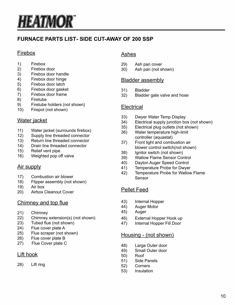
siDe cut-aWay vieW OF heatMOr™ 200 ssP OutDOOr Furnace(For parts not shown on the cut-away view, please refer to the appropriate chapter for further details.)
chaPter 3
10
Furnace Parts List
Firebox
1) Firebox2) Firebox door3) Firebox door handle4) Firebox door hinge5) Firebox door latch6) Firebox door gasket 7) Firebox door frame8) Firetube 9) Firetube holders (not shown)10) Firepot (not shown)
Water jacket
11) Water jacket (surrounds firebox)12) Supply line threaded connector 13) Return line threaded connector 14) Drain line threaded connector15) Relief vent pipe16) Weighted pop off valve
Air supply
17) Combustion air blower18) Flipper assembly (not shown) 19) Air box 20) Airbox Cleanout Cover
Chimney and top flue
21) Chimney 22) Chimney extension(s) (not shown)23) Tubed flue (not shown)24) Flue cover plate A25) Flue scraper (not shown)26) Flue cover plate B27) Flue Cover plate C
Lift hook
28) Lift ring
Ashes
29) Ash pan cover30) Ash pan (not shown)
Bladder assembly
31) Bladder32) Bladder gate valve and hose
Electrical
33) Dwyer Water Temp Display 34) Electrical supply junction box (not shown)35) Electrical plug outlets (not shown)36) Water temperature high-limit controller (aquastat)37) Front light and combustion air blower control switch(not shown)38) Ignitor switch (not shown) 39) Watlow Flame Sensor Control40) Dayton Auger Speed Control41) Temperature Probe for Dwyer42) Temperature Probe for Watlow Flame Sensor
Pellet Feed
43) Internal Hopper44) Auger Motor45) Auger46) External Hopper Hook up47) Internal Hopper Fill Door
Housing - (not shown)
48) Large Outer door 49) Small Outer door 50) Roof51) Side Panels52) Corners53) Insulation
- siDe cut-aWay OF 200 ssP

11
MiniMuM cLearance seParatiOn sPeciFicatiOns The HEATMOR™ furnace, is certified to be installed outside, away from other buildings. Please observe the following “Clearance to Combustibles” guidelines. If you have any further questions, which are not addressed in this Operators Manual, please contact your local dealer for further information.
♦ To HEATMOR™ Stainless Steel Outdoor Furnace Back. 96 inches ♦ To HEATMOR™ Stainless Steel Outdoor Furnace top. 18 inches ♦ To HEATMOR™ Stainless Steel Outdoor Furnace Front. 48 inches ♦ To HEATMOR™ Stainless Steel Outdoor Furnace chimney. 18 inches ♦ To HEATMOR™ Stainless Steel Outdoor Furnace sides. 6 inches ♦ Do not store combustible liquids or materials near the furnace. ♦ It is not recommended to install the furnace in any form of building. Before installing your HEATMOR™ Stainless Steel Outdoor Furnace, if in the united states, always check any and all applicable state and local regulations and inform your insurance agent.
Before installing your HEATMOR™ Stainless Steel Outdoor Furnace, if in canada, always check any and all applicable Provincial and Municipal regulations and inform your insurance agent.
HEATMOR™ Inc. strongly recommends not installing a HEATMOR™ Stainless Steel Outdoor Furnace within 50 feet of any flammable structure.
A HEATMOR™ Stainless Steel Outdoor Furnace should be located with consideration to your neighbor’s property and in accordance with local ordinances. Refer to the “Best Burn Practices” for further operating considerations.
HEATMOR™ Outdoor Furnace, is not designed or certified to be located in densely populated areas.
chaPter 4

12
Warnings anD PrecautiOns
Please read the following list of cautions, warnings and dangers before installing and operating your heatMOr™ stainLess steeL OutDOOr Furnace. if you have any questions or concerns regarding any of the following cautions, warnings, dangers or instructions in this Operations and Maintenance manual, please contact your local dealer. Familiarize yourself with the “Best Burn Practices” located on the inside front cover.
Installation
Installation should be performed by a qualified installer and will comply with all the requirements of the authority having jurisdiction over the installation.
1) The HEATMOR™ furnace is designed for outside installations, away from other buildings. 2) Please observe the following “ Clearance to Combustibles “ guidelines.
To unit back = 96 inches To unit sides = 6 inches To unit front = 48 inches To chimney = 18 inches To unit top = 18 inches
3) Before installing the furnace, always check any and all applicable state, provincial, and local regulations. 4) HEATMOR™ Inc. strongly recommends not installing a HEATMOR™ Stainless Steel Outdoor Furnace within 50 feet of any flammable structure. 5) A HEATMOR™ Stainless Steel Outdoor Furnace should be located with consideration to your neighbor’s property and in accordance with local ordinances. The HEATMOR™ Outdoor Furnace is not designed to be located in densely populated areas. 6) HEATMOR™ suggests the use of brass fittings when installing the unit. 7) Before installing the HEATMOR™ furnace, contact and inform your insurance agent.
8) The HEATMOR™ Outdoor Furnace is to be installed on a concrete base only. Any attempt to place the furnace on any other surface may void the warranty. 9) Do not connect the HEATMOR™ furnace to the chimney of any existing heating system. 10) This unit was not designed, nor is it recommended, for use as a stand-alone heating system. A back up source of heat must be in place to prevent the outdoor furnace from freezing and to provide supplementary heat for the heated buildings. 11) Do not pressurize the HEATMOR™ Outdoor Furnace. This unit is designed to operate under atmospheric pressure only. 12) Place the in-line fill/drain assembly in a location where the drained contents of the HEATMOR™ will not cause damage to the surrounding areas or it’s contents.
chaPter 5

13
Electrical
1) Do not connect the electrical components of the HEATMOR™ Outdoor Furnace to any other electrical appliance. 2) This HEATMOR™ Outdoor Furnace operates on 115-volt power only. Do not connect the furnace to a 220- volt electrical supply. Use 14-3 wire. 3) heatMOr™ inc. recommends a licensed professional electrician make all the necessary electrical connections involved with the installation of the furnace. 4) Always disconnect the HEATMOR™ Outdoor Furnace from the main electrical supply before servicing any of the electrical components of the HEATMOR™ Outdoor Furnace. 5) Always disconnect any existing electrical connections to any in-house heating system, before installing the outdoor furnace to any existing indoor heating system or appliances. 6) The red wire from the high-limit aquastat on the back of the HEATMOR™ should be wired to the indoor temperature control to override the thermostat. This will dissipate excess heat in the event of a possible malfunction with the HEATMOR™. (the red wire is capped off in the electrical junction box when the heatMOr™ is new.)
Other
1) The unit may be connected to an existing indoor boiler system by installing a water-to-water heat exchanger.
1) heatMOr™ inc. recommends that you contact a licensed professional plumber to make all necessary plumbing installations between the heatMOr™ furnace and the existing heating system of your building(s). 2) Do not operate the heatMOr™ furnace until all electrical and water line connections have been properly installed and tested. 3) Do not allow any fire in the firebox until the HEATMOR™ has the correct amount of water installed.

14
chaPter 6
7”
BASE: OUTDOOR FURNACE SITS ON THIS PAD
Hole for Plumbing
67.5”
18”
9”12”
OUTDOOR FURNACE SITS HERE GROUND LEVEL
UNDERGROUND LINES
200 ssP PaD sPeciFicatiOns
The actual pad size is 36” x 67.5”. This gives approximately 1” extra on all sides of furnace. CAUTION: Do not exceed this length measurement. Width can be wider if desired.
The internal hopper opening is 43” above ground or base of furnace.
If patio stones or a separate cement pad are put around the cement pad for the HeatmorTM, they should nOt be attached to main base pad of furnace.
It is recommended to make the pad 4” thick and use steel mesh or R-bar in pad for strength.
INTERNAL HOPPER
DOOR
36”
SIDE VIEWOUTDOOR FURNACE SITS HERE
FOUR INCH GRAVEL BASE
CEMENT BASE
15
instaLLatiOn OF the heatMOr™ Furnace
Installation should be performed by a qualified installer and will comply with all the requirements of the authority having jurisdiction over the installation.
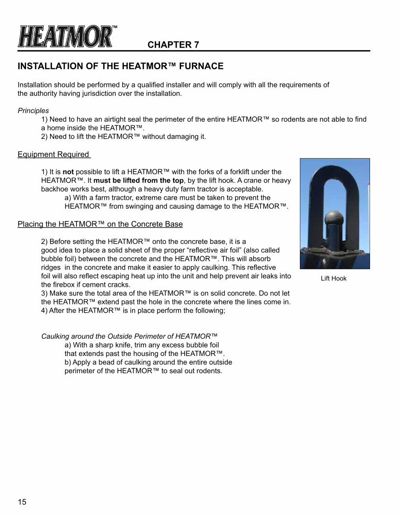
Principles 1) Need to have an airtight seal the perimeter of the entire HEATMOR™ so rodents are not able to find a home inside the HEATMOR™. 2) Need to lift the HEATMOR™ without damaging it.
Equipment Required 1) It is not possible to lift a HEATMOR™ with the forks of a forklift under the HEATMOR™. It must be lifted from the top, by the lift hook. A crane or heavy backhoe works best, although a heavy duty farm tractor is acceptable. a) With a farm tractor, extreme care must be taken to prevent the HEATMOR™ from swinging and causing damage to the HEATMOR™.
Placing the HEATMOR™ on the Concrete Base 2) Before setting the HEATMOR™ onto the concrete base, it is a good idea to place a solid sheet of the proper “reflective air foil” (also called bubble foil) between the concrete and the HEATMOR™. This will absorb ridges in the concrete and make it easier to apply caulking. This reflective foil will also reflect escaping heat up into the unit and help prevent air leaks into the firebox if cement cracks. 3) Make sure the total area of the HEATMOR™ is on solid concrete. Do not let the HEATMOR™ extend past the hole in the concrete where the lines come in. 4) After the HEATMOR™ is in place perform the following;
Caulking around the Outside Perimeter of HEATMOR™ a) With a sharp knife, trim any excess bubble foil that extends past the housing of the HEATMOR™. b) Apply a bead of caulking around the entire outside perimeter of the HEATMOR™ to seal out rodents.
chaPter 7
Lift Hook

16
Filling the HEATMOR™ Outdoor Furnace Initially with Water
Before filling your HEATMOR™ furnace with water, all plumbing connections at the back of the HEATMOR™ furnace, all electrical hookups, and all heating appliances should be installed and tested for possible leaks. HEATMOR™ suggests the use of brass fittings when installing the unit.If you have any questions regarding installation of the furnace or any aspect of installation, contact your local dealer. Note: Never start a fire inside the firebox until the water jacket is full of water.
1) Close the bladder gate valve located at the front of the HEATMOR™ furnace. This valve will ensure no water can enter the bladder. 2) Close the bottom supply line valve at the front of the HEATMOR™. 3) Open the top return line valve at the front of the HEATMOR™. 4) Remove the weighted ball on the roof of the furnace from the relief vent pipe. 5) Connect the water source to the return line leading to the HEATMOR™. Use a garden hose to add the water to the return line. 6) Turn on the source of water. 7) The pressured water will now flow through and remove the air out of the return line as the water flows into the HEATMOR™. 8) Continue adding water until water flows out the relief vent pipe, onto the roof of the HEATMOR™. 9) Turn off the source of water. The HEATMOR™ is now full of water and the return line is also full of water and air free, BUT the supply line leading from the HEATMOR™ to the building to be heated is still full of air.
10) Close the top return line valve at the front of the HEATMOR™. 11) Remove the garden hose that was used to deliver the source of water from the top return line, BUT leave the garden hose valve open. 12) Open the bottom supply line at the front of the HEATMOR™ (bottom). The pressure of the water in the HEATMOR™ will now force water from the HEATMOR™ through the supply line back into the building to be heated. This water will soon discharge from where the garden hose was connected. When there is a steady stream of water flowing, the air will be removed from that supply line. Usually it requires the removal of approximately five gallons of water to ensure the line is air-free.
NOTE: The circulator pumps cannot “push” much air through a system. They are designed to move water not air.
13) Start the circulating pump. Remember to properly bleed air from the pump.
Rear of Furnace

17
aBsOLuteLy nO Fire in the FireBOX When PerFOrMing this rePair. DO nOt PerFOrM this rePair When unit Water teMPerature is unsaFe. aLWays Wear PrOPer
PersOnaL PrOtective eQuiPMent When WOrKing With Water anD cheMicaLs.
Maintaining the Correct Amount of Water in the Bladder and in the HEATMOR™
1) Close the bladder gate valve located at the front of the HEATMOR™ furnace. Closing this valve will ensure no water can enter the bladder. 2) Remove the weighted ball from the relief vent pipe. 3) Connect the water source to the return line leading to the HEATMOR™. Use a garden hose to add the water to the return line. 4) Turn on the source of water, but only about half a full flow. 5) The pressured water will now flow through the return line as the water flows into the HEATMOR™. 6) Continue adding water until water flows out the relief vent pipe, onto the roof of the HEATMOR™. Leave the water running. Some may continue to spill out onto the roof. 7) Place the weighted ball back onto the relief vent pipe. 8) Turn on the green bladder gate valve and let the bladder fill half full. You can check this by feeling the bladder with your hand inserted through the bladder inspection cover plate. 9) Turn off the water when the bladder is half full.
Low Water Condition
If the water level is below the bladder port when the water heats up, air will enter the bladder instead of water. To remove the air from the bladder, follow steps 1 through 7 above and make sure there is a good seal on the weighted ball. Next:
1) Open the bladder gate valve. 2) CAREFULLY remove the bladder hose, allowing the bladder to empty its contents. 3) After bladder is empty of air/water, re-attach the bladder hose to the bladder gate valve and tighten the hose clamp.
Next, follow steps 7-9 above. nOte: never Light a Fire insiDe the FireBOX untiL the Water JacKet is FuLL OF Water.
instaLLatiOn shOuLD Be PerFOrMeD By a QuaLiFieD instaLLer anD WiLL cOMPLy With aLL the reQuireMents OF the authOrity having JurisDictiOn Over the instaLLatiOn.
reaD thrOugh the entire OPeratiOns anD Maintenance ManuaL BeFOre OPerating yOur heatMOr stainLess steeL OutDOOr Furnace.
18
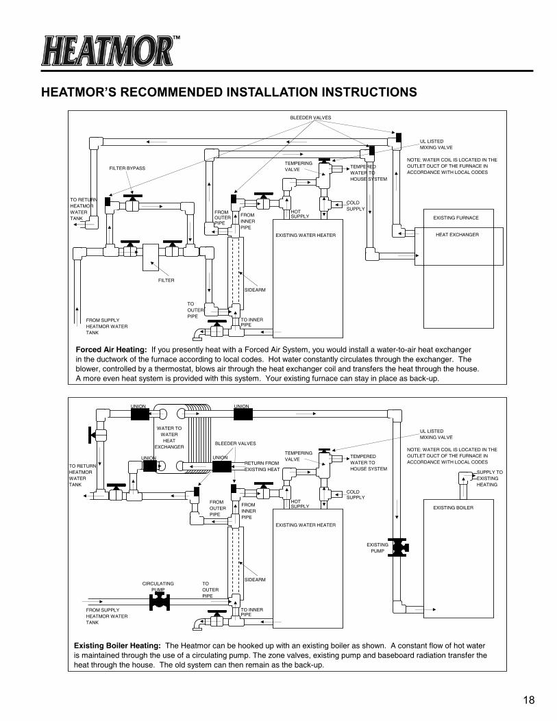
heatMOr’s recOMMenDeD instaLLatiOn instructiOns
Forced Air Heating: If you presently heat with a Forced Air System, you would install a water-to-air heat exchangerin the ductwork of the furnace according to local codes. Hot water constantly circulates through the exchanger. The blower, controlled by a thermostat, blows air through the heat exchanger coil and transfers the heat through the house.A more even heat system is provided with this system. Your existing furnace can stay in place as back-up.
FROM SUPPLYHEATMOR WATERTANK
TO RETURNHEATMORWATERTANK
FILTER
SIDEARM
HEAT EXCHANGER
EXISTING FURNACE
EXISTING WATER HEATER
BLEEDER VALVES
FILTER BYPASSTEMPERINGVALVE
TEMPERED WATER TO HOUSE SYSTEM
COLD SUPPLYHOT
SUPPLY
NOTE: WATER COIL IS LOCATED IN THEOUTLET DUCT OF THE FURNACE IN ACCORDANCE WITH LOCAL CODES
UL LISTED MIXING VALVE
TO INNERPIPE
TOOUTERPIPE
FROMINNERPIPE
FROM OUTERPIPE
Existing Boiler Heating: The Heatmor can be hooked up with an existing boiler as shown. A constant flow of hot water is maintained through the use of a circulating pump. The zone valves, existing pump and baseboard radiation transfer theheat through the house. The old system can then remain as the back-up.
FROM SUPPLYHEATMOR WATERTANK
SIDEARM
EXISTING BOILER
EXISTING WATER HEATER
BLEEDER VALVES
TEMPERINGVALVE
TEMPERED WATER TO HOUSE SYSTEM
COLD SUPPLY
HOTSUPPLY
NOTE: WATER COIL IS LOCATED IN THEOUTLET DUCT OF THE FURNACE IN ACCORDANCE WITH LOCAL CODES
UL LISTED MIXING VALVE
TO INNERPIPE
TOOUTERPIPE
FROMINNERPIPE
FROM OUTERPIPE
CIRCULATINGPUMP
SUPPLY TOEXISTING HEATING
EXISTINGPUMP
UNION
RETURN FROM EXISTING HEAT
UNION
WATER TO WATER HEAT
EXCHANGER
UNION
UNION
TO RETURNHEATMORWATERTANK

19
FILTRE
DÉRIVATION DU FILTRE
PLINTHE
THERMOSTAT
In-Floor Heating: To install an In-Floor Heating system, hot water pipes are placed in the floor at the time your slab ispoured. Water circulates through the tubing and heats the concrete which radiates and heats the building. Valves are used to control water flow in each loop, manual control valves are used between manifolds for temperature control, and electric zone valves are used for more even heat. Thermostats are used to individually control the heat in any part of thebuilding.
FROM SUPPLYHEATMOR WATERTANK
TO RETURNHEATMORWATERTANK
FILTER
FILTER BYPASS
SLAB
ZONE VALVE
SHUT OFFVALVES
COPPER TEE
COPPER TO POLYBUTYLENE ADAPTOR
CRIMP RING
POUR REVENIR AU RÉSERVOIR D’EAU DE LA HEATMOR
DE L’ALIMENTATION DU RÉSERVOIR D’EAU DE LA HEATMOR(MD)
VANNE À TROIS VOIES DE RÉGULATION PAR
ZONE
Plinthes à eau chaude: Pour un système de plinthes à eau chaude (ressemblant à des plinthes de chauffage électrique), les plinthes sont installées dans le périmètre de l’édifice. La température des pièces est individuellement contrôlée par les vannes de régulation par zone et les thermostats.

20
Water Heater: The Heatmor is designed to provide all your hot water needs. A water-to-water heat exchanger is installed vertically along side the domestic water heater. This hook-up initiates a thermo-siphon action that continues24 hours/day. The gas or electric element in your water tank will not have to come on.
TO RETURNHEATMORWATERTANK
SIDEARM
EXISTING WATER HEATER
TEMPERINGVALVE
COLD SUPPLYHOT
SUPPLY
TO INNERPIPE
TOOUTERPIPE
FROMINNERPIPE
FROM OUTERPIPE
UL LISTED MIXING VALVE
FROM SUPPLYHEATMOR WATERTANK
OTHER APPLICATIONS
Pools/Hot Tubs: The Heatmor can also be used to heat your swimming pools and hot tubs. A water to water heatexchanger is used for this application.
Sidewalks/Driveways: The Heatmor can also be used to melt snow and ice from your sidewalk and/or driveway. Tubingis laid beneath the concrete. The heated water circulates through the slab melting the snow and ice before it has a chance to stick. This application greatly reduces the labor involved in shoveling.
Unit Heater(Fan/Coil Unit): A unit heater (forced air water heater) can be placed at the ceiling, in a cabinet, or built intothe floor or wall. Hot water from the Heatmor circulates throught he exchanger and the heat is extracted with an enclosedthermostatically controlled blower. Each heater is thermostatically controlled.
21
saFe Furnace OPeratiOn guiDeLines OPERATION
heatMOr™ OutDOOr Furnace 200 ssP is certiFieD tO Burn WOOD PeLLets OnLy.
Burning of other materials may result in serious burns, health consequences, or damage to this furnace and other components of the heating system and may void warranty.
***iMPOrtant nOtice*** PLEASE REFER TO “LIGHTING THE HEATMOR™ FOR THE FIRST TIME” AND “LOADING WOOD PELLETS INTO THE HEATMOR™”, FOR ADDITIONAL SAFE LOADING PROCEDURES.
1) Never open the firebox door if the combustion air blower is operating or if you suspect a roaring hot fire inside the firebox. 2) Never open the firebox door immediately after the combustion air blower has shut off. If the water temperature is very close to the high setting, you should assume the air combustion fan has just shut off. 3) If there is more than a “wiff” of exhaust coming from the chimney and the draft fan is off, do not open the firebox door for at least two minutes. The burn cycle would have just ended and the firebox will be full of unburned gases (exhaust) that may ignite when fresh air is introduced. 4) Load the unit with wood pellets carefully. After loading wood pellets make sure all debris is cleaned from the hopper door. Then close hopper door securely. 5) Keep the firebox door, ash pan cover plate, all three flue cover plates, hopper door, airbox cover plate and the outer doors of the HEATMOR™ furnace closed at all times except for servicing and refueling. 6) Keep the locking handle on the outer doors locked at all times when not servicing or refueling to reduce the risk of tampering and possible injury. 7) Never add water to the HEATMOR™ furnace if the internal water temperature is over 212 degrees Fahrenheit. Failure to adhere to this warning may cause a steam flash and result in an explosion. 8) Do not store combustible liquids or materials near the outdoor furnace. Adhere to the “Clearance to Combustibles” guidelines. 9) Never use gasoline, kerosene, charcoal, lighter fluid or similar liquids to start, re-start or freshen up a fire. Using such liquids may result in severe burns and injury. 10) When adding water, water treatment or loading or maintaining the HEATMOR™ furnace, protective clothing must be worn at all times.
chaPter 8

22
11) never leave the HEATMOR™ furnace unattended while the firebox or hopper door is open or unlatched. 12) Stay clear of any exhaust emitting from the firebox. 13) Do not burn corn, garbage, plastics, rubber, naptha, trash, tires, solvents, engine oil, gasoline, leaves, paper products, cardboard, material treated with petroleum products (particleboard, railroad ties and pressure treated wood) or other inappropriate materials. 14) Store ashes outside, in a metal container with a metal tight fitting lid, away from the outdoor furnace and other buildings. No other waste should be placed in this container. 15) Wear a particle mask when removing ashes. 16) Ash pan may be hot after removing ashes. 17) In case of power failure, do not open any doors on the HEATMOR™. Monitor the water temperature very closely. Refer to “freeze protection” in this manual. 18) In below freezing weather, if the water temperature in the HEATMOR™ drops below 40 degrees Fahrenheit, drain all water from the HEATMOR™ immediately (if there is no anti-freeze in your system). 19) Water additives supplied with a HEATMOR™ do not give any freeze protection. 20) Always remove the weighted pop off ball before removing more than 5 gallons of water from the HEATMOR™.

23
Lighting the HEATMOR™ for the First Time
When lighting the HEATMOR™ furnace for the first time, all installations must be complete and the furnace must be full of water. It is recommended to open bladder valve, reinstall the pop-off ball, and then build fire to bring the water up to temperature. This will help prevent the bladder from over expanding. The lighting process is fairly simple. Please use the following steps simply as a guideline or contact your local dealer for further instruction. read the entire manual before lighting, so you have a complete working knowledge of the furnace. Ask for a demonstration from your local dealer. it is very important to fully educate all persons who will be lighting and fueling the heatMOr™ furnace.
PLEASE READ THROUGH ALL “LIGHTING YOUR HEATMOR™” STEPS BEFORE LIGHTING YOUR FURNACE.
1) Remove the weighted pop off ball from the relief vent pipe, on top of the HEATMOR™ furnace. 2) Close the green valve, supplying the bladder, located at the rear of the furnace. 3) ensure that the furnace is full of water by running five gallons of water onto the roof of the HEATMOR™. 4) Replace pop off ball and open green bladder valve. 5) Ensure that there is 115-volt electrical power supplying the HEATMOR™ furnace. 6) Fill the internal hopper with wood pellets. 7) Turn both the fan switch and the ignition switch at the side of the furnace(inside the big door, on your upper left) to the on position (up) 8) Go to the front of the furnace and turn the Watlow Flame Sensor to 0F (this will allow the auger to feed pellets into the burn chamber) 9) Wait for 40 seconds for wood pellets to feed into the burn chamber then turn the Watlow Flame Sensor back to 200F. Note it may take more than 40 seconds for pellets to feed into the firepot if the auger is completely empty. 10) Wait for ignition. You should see some smoke coming from the chimney. Note: When the firebox reaches the Watlow Sensor setting of 200F the auger will start. 11) Once the ignition is evident, turn off the ignition switch (the switch closer to the furnace) but leave the fan switch on (the switch closer to you) NOTE: Before the furnace is fired up, the furnace is filled with water. While the furnace is filling with water, the bladder is shut off to prevent excess water into the bladder, preventing over fill. When the furnace is freshly filled the water temperature is approximately 50 degrees Fahrenheit. When the furnace is full of water you will notice water coming out onto the roof from the relief vent pipe. At this point the water should be turned off and the bladder valve opened. After the furnace is fired up, the water temperature will start to increase. While the water temperature rises, the water will expand as it heats up, causing the excess water to go into the bladder. It will go into the bladder because it is the place of least restriction. This is another reason why we do not fill the bladder initially, too much water in the bladder at cooler temperatures could cause the bladder to overfill at higher temperatures caused by the expansion of the water during temperature rise.

24
DEW POINT
nOte: As the temperature inside of the firebox is increasing, there will be some sweating inside the firebox. There may be streams of water running down the inside firebox walls and down the inside of the firebox door. Water may run out onto the fan cover, below the firebox door, out of the flue covers, and even out the ash pan. the heatMOr™ is nOt LeaKing!
Just as moisture collects on the inside of a warm house window on a cold outside day, the same thing is occurring inside the HEATMOR firebox. The warm moisture in the exhaust is condensing on the cold firebox walls of the HEATMOR. In most typical situations, once the water temperature is above approximately 130 degrees Fahrenheit, the sweating will stop because you are above the dew point.
Loading Wood Pellets into the HEATMOR™
Please read through the entire HEATMOR™ Operation and Maintenance Manual and talk to your local dealer for instruction. Ask for a demonstration from your local dealer. it is very important to fully educate all those who will be loading the furnace with wood pellets.
We suggest to set the Dayton auger speed control to 80 +/-5. Set the speed control to 80 then observe daily ash removals for unburnt pellets. If there is some unburnt pellets in the ash pan then trying lowering the speed control. If the furnace is not keeping up to your heatload, i.e. the unit is not getting up to temperature when your house is calling for heat, try increasing the speed control. The optimum speed control setting will very depending on what types of pellets you are using and the amount of heat being removed.
Here are some suggested points to assist you in loading pellets into your furnace.
1) Make sure you have your fuel readily available to fill your furnace. (ie. wood pellet bags near the furnace and the tops cut open) 2) Maintain a clear, clean area in front and at the side of the furnace. 3) Open the small outer front door. 4) Open the internal hopper door. 5) Slowly pour the wood pellets into the internal hopper. The internal hopper can hold 4 - 40lb bags if it is completely empty. 6) Pour pellets into the hopper until it is full and the hopper door can close securely without restriction. 7) Close the internal hopper door. 8) Close the small outer door and latch securely.

25
What should I burn?
this furnace is designed to burn soft or hard wood pellets OnLy.
Wood pellets are generally made from compacted sawdust; they are usually a byproduct of saw milling or other wood transformation activities. They are very dense in formation and generally come in 40 pound bags. They will be either 6mm or 8mm in diameter. Lower ash content pellets are suggested.
Pellet Fuels Institute has standards and a vast amount of information on the internet available. You can go to www.pelletheat.org for more information.
You should properly store the pellets for the most efficient combustion. See “Handling and Storage of Wood Pellets” for more information. Properly stored wood pellets will have a moisture content of 2-5%.
How does a fire burn out?When the temperature of the water has reached its high limit (185 degrees Fahrenheit), the combustion air blower(s) shut off. At this point, the fire “banks”. When the air combustion blower(s) turn back on, there may not be enough coals to restart the fire. You will then need to restart the fire using the manual ignition. If this situation occurs often and the weather is fairly warm, you may want to transfer to your standard system for better efficiency.
A new unit will require the establishment of “bed of coals” which will aid in re-establishing proper combustion. This may take a few burn cycles.
Stages of Combustion During the four stages of combustion, wood breaks down into water, smoke and charcoal. The first stage occurs when the wood pellets are augered into the firebox. The pellets must be heated to drive off the moisture. The higher the moisture content, the greater the amount of heat needed and subsequently lost for heating purposes. The drier the wood pellet, the more rapidly it can be heated and passed through this first stage of heating the water. When moisture is being driven from the wood pellets, white smoke may be emitted from the chimney. This is what we call “steam smoke”. It is mostly water vapor. In the second stage, at 500 degrees Fahrenheit, wood begins to break down chemically. If this smoke is released but not burned, two-thirds of the energy in the wood will be lost. A hot fire is needed to burn the smoke. The third stage takes place at temperatures above 1100 degrees Fahrenheit. At this point, the smoke is burning at 100 percent efficiency, as long as the proper amounts of oxygen, temperature and draft are present. If one of these elements is missing, the combustion will be incomplete. The third stage is the most important stage of wood combustion since smoke represents two-thirds of the wood heat. The fourth stage takes place after 1100 degrees Fahrenheit to 2000 degrees Fahrenheit temperatures have been reached. The smoke and gases are completely burned and the charcoal remains, which represents approximately one-third of the wood heat, and allows the fire to re-start when required.
Please refer to the “Outdoor Wood Furnace Best Burn Practices” located on the inside front cover of this manual.

26
When a new charge of wood pellets are augered into the firebox, the first stage of combustion begins again. The charcoal heats the fresh wood until it gets hot enough to react and ignite, and the process continues. All four stages can take place concurrently but complete combustion requires proper placement of secondary air and adequate temperatures. This is incorporated in the design of the Heatmor furnace.
Efficiency Measurements
There are different ways of expressing efficiency and to correctly compare values.
Combustion Efficiency - Input BasedThe amount of fuel that is completely burned compared to the total amount available for combustion expressed as a percentage. For example: An open bonfire; 100 pounds of wood burns and produces three pounds of ash, which equals 97 percent combustion efficiency. Good combustion efficiency but poor heating efficiency. No heat got into the house.
Heating Efficiency - Output BasedThe percentage of the heat produced that was actually absorbed into the water and transferred into the house from the HeatmorTM.
Net EfficiencyThis is the product of the combustion and heating efficiencies. Ninety percent combustion efficiency times 60 percent heating efficiency results in a 54 percent net efficiency.
Handling and Storage of Wood Pellets
Common questions concerning wood pellet storage.
1) Q. Do I have to keep my wood pellets covered?
a. Yes, it can be more convenient. It is an extra task if snow has to be knocked off the bags before they are brought to the furnace for opening and pouring into the hopper. It will also prevent rain and snow landing on the any exposed wood pellet bags that could add a certain amount of moisture to the wood pellets. Refer to “first stage of the burning process.” 2) Q. Why is it important to have my loading of wood pellets directly at the furnace when I go to load my furnace? a. Because it is best to always keep a tight seal on the hopper door to prevent any possibilities of burn back.
3) Q. Is it a good idea to put the front of my HEATMOR™ into my wood storage building so I can load the HEATMOR™ from inside?
a. This is never a good idea. The HEATMOR™, is designed to be placed outside away from all buildings to maintain optimum safety. Refer to the “Clearance to Combustibles” section.

27
4) Q. What is the best method of handling wood pellets?
a. Handle wood pellets as little as possible. Keep the wood pellets covered. Keep the wood storage area neat and tidy. If you have a tractor that can lift pallets, you are well on your way to solving all three concerns. Buy the wood pellets by the pallet and you can store the pallets not too far from the HEATMOR™. Cover them if you wish. Use the tractor to bring the pallets to the front of the HEATMOR™, as you need them. Refer to the “Clearance to Combustibles” section.
5) Q. Do I need to hook up an external hopper?
a. The use of a external hopper is optional. You can take advantage of buying your pellets in bulk and having a place to store them in the external hopper. You would also not have to load your pellets as often, though you should still clean your ash pan daily.
28
Water
Qualities of Water to Use Water quality will vary from one location to another. Different qualities of water can have a damaging effect on your HEATMOR™ furnace, pumps, and plumbing components. Please observe the following guidelines for best results.
• Do not add water from ponds or off roofs. • Do not add water exceeding 50 parts per million (ppm) in chlorides. • Do not add water over 27 grains hardness - mix this water 50/50 with softened water. • Do not add water exceeding 50 ppm silica content. • Do not add water from shallow wells. • Do not add water from a well that has recently been “shocked” with chlorine. • The best mixed water is 50/50 reverse osmosis/distilled and softened water.
Water Level Maintenance
You can verify the water level of your HEATMOR™ by checking the fullness of the bladder. The water level gauge (“add water” weight) inside the front door should be up near the bladder, not down near the hopper. An even better method of gauging the fullness of the bladder is to reach up through the bladder cover plate and feel the bladder. The bladder should still have wrinkles in it when the water temperature is 180 degrees Fahrenheit. If the filling procedures were done correctly, the bladder would have been the last thing topped up after the water jacket of your HEATMOR™. Refer to “Filling your Furnace Initially” for further details or contact your local dealer.
Removal/Replacement of System Water
Before removing more than five gallons of water from your HEATMOR™, make certain to remove the weighted pop off ball so that air can enter the water jacket as water leaves. Failure to do so may put a negative pressure on the water jacket and collapse it. Warranty does not cover this.If a sediment faucet was installed at the back of furnace, it may be used for draining purposes. If you have a sediment faucet installed on the main manifold in the house, that also can be used to drain the HEATMOR™. the drained contents of the heatMOr™ must be discharged to an area or place where they will not damage property or create an environmental hazard. if you are draining the system because of total system shutdown in cold weather, remember to also drain the supply and return lines to prevent freeze-up.
To refill your HEATMOR™, refer to “Filling your Furnace Initially.” It is important to add water treatment to the HEATMOR™ once you have refilled your HEATMOR™. For further information on replacing the water in your furnace, contact your local dealer.
chaPter 9
29
Water Additives
Principles of Water Treatment 1) Minimize the corrosion potential of system metallurgy. 2) Keep water in the 8 to 10 pH range. 3) Acts as an oxygen scavenger. 4) Water treatment supplied with the heatMOr™ does not give any freeze protection. 5) With proper chemical control, longer equipment life can be achieved. 6) Maintain the Molybdate in the operating range of 200-300ppm.
addition of Water treatment When installing a completely new system, we recommend that the system first be filled with water only. After two or three days of operation, check that all air is out of the system, and all connections are leak free. Once the entire system is confirmed to be leak free, add the water treatment.
To add water treatment to the HEATMOR™ furnace, follow these steps. 1) Before adding the treatment, drain out a corresponding amount of water. 2) Remove the weighted pop off ball from the relief vent pipe. 3) Take a funnel and place it into the relief vent pipe. 4) Pour the entire contents of the water treatment chemical, as supplied, into the HEATMOR™ furnace. 5) Top up your HEATMOR™ furnace with water, fill the bladder, and replace the pop off ball. Refer to “Filling the Bladder Initially” for details or contact your local dealer.
Water Treatment Maintenance / ResultThe water in the HEATMOR™ should be chemically analyzed once per year to ensure the proper levels of treatment are being maintained. Send a sample of water from your HEATMOR™, equal to approximately 20 ounces, in a clean container to :
Heatmor, Inc.PO Box 787
Warroad, MN 56763
or you can also send the sample to your local dealer.
The amount of water treatment that has to be added yearly is dependent on how much fresh water you have added to your system since the last test. Be certain to add a water treatment that is approved by your dealer and HEATMOR™ Inc.
aBsOLuteLy nO Fire in the FireBOX When PerFOrMing this rePair. DO nOt PerFOrM this rePair When unit Water teMPerature is unsaFe. aLWays Wear PrOPer
PersOnaL PrOtective eQuiPMent When WOrKing With Water anD cheMicaLs.

30
Water Treatment Additives and Safety Specifications
Water Treatment Safety Specifications
Danger: cOrrOsive MateriaL - causes Burns
cautiOn: KeeP Out OF the reach OF chiLDren
Product Identification: Control Water Stove Treatment and Rust Inhibitor
Product Manufacturer: Image Supply Inc.
Contents: Sodium Nitrate Potassium Hydroxide Hidacid Azure Blue Dye Water
Danger: Harmful or fatal if swallowed. Avoid skin, clothing and eye contact Avoid breathing mist or vapors Keep container closed and away from children First Aid: Skin Contact: Immediately flush skin with plenty of water. Remove contaminated clothing and shoes. Wash clothing before reuse. Call a physician if irratation develops and persists. Eye Contact: Immediately flush eyes with plenty of water for at least 15 minutes. Inhalation: Move to fresh air. Ingestion: Harmful or fatel if swallowed. Give several glasses of water followed by citrus juice then olive oil. Get medical attention. NEVER GIVE ANYTHING BY MOUTH TO AN UNCONSCIOUS PERSON
Handling instructions: Wear eye/face protection. Wear goggles and Alkali resistant gloves. Wear suitable protective clothing.
Clean up: Contain and/or absorb spill with inert material(e.g. sand, vermiculite), then place in a suitable container. Do not flush to sewer or allow to enter waterways. Use appropriate Personal Protective Equipment. Neutralize area with vinegar. Wash contaminated clothing before reuse.
Other precautions: Do not leave unattended when open. Do not reuse container. This product does not provide any freeze protection.
FOR MEDICAL EMERGENCIES CALL
United States: INFOTRAC 1-800-535-5053 Canada: 1-800-268-9017
31
Freeze Protection
Principles of Freeze ProtectionWhen the total system is operating as designed, there is no need to add anti-freeze. However if the water in the outdoor furnace is not going to be kept above 50 degrees Fahrenheit in cold weather, freeze protection must be considered. In a properly designed system, the indoor appliances will automatically come on, generate heat, and keep the supply line, return line, and outdoor furnace from freezing by transferring some of the heat generated, back to the outdoor furnace. This will only happen if the circulating pumps are running. it is recommended to always have a backup system in place. • Freeze protection products have lower heat transfer capabilities than water. • Freeze protection products will not necessarily inhibit corrosion. • Some insurance companies will not insure an outdoor furnace with glycol in the system. • Ensure the correct freeze protection product is used. non-toxic, propylene glycol based, boiler antifreeze is recommended. One such product is DOWFROST HD™ from Dow Chemicals or Harvey Heat.
Before draining the water, please refer to “removal/replacement of system Water”.
When installing a completely new system, we recommend that the system first be filled with water only. After two or three days of operation, check that all air is out of the system, and all connections are leak free. Once the entire system is confirmed to be leak free, add the water treatment. Before adding the treatment, drain out a corresponding amount of water.
Adding Freeze Protection Products
1) Remove the weighted pop off ball. 2) Drain the correct amount of water from the system for the products being added. 3) Take a funnel and place it into the relief vent pipe. 4) Pour the contents of the freeze protection products, into the HEATMOR™ furnace. Do not pressurize the heatMOr™; do not attempt to thread fittings onto the relief vent pipe and “pump” additives into the HEATMOR™ under pressure. 5) Top off your furnace with water, fill your bladder, and replace pop off ball. Refer to “Filling the Bladder Initially” for details or contact your local dealer.
aBsOLuteLy nO Fire in the FireBOX When PerFOrMing this rePair. DO nOt PerFOrM this rePair When unit Water teMPerature is unsaFe. aLWays Wear PrOPer
PersOnaL PrOtective eQuiPMent When WOrKing With Water anD cheMicaLs.

32
BLaDDer asseMBLy
PrinciplesIt is best not to have the system water, that is in the water jacket, exposed to the atmosphere. This is because of system water loss through evaporation. When system water is lost, it must be replenished or soon the water jacket would be empty. Not only is replenishing lost system water a nuisance, it is also accelerating the corrosion process throughout the total system, because adding fresh system water is also adding more corrosion causing minerals. The challenge is to maintain an airtight system, while at the same time, allowing for the expansion and contraction of system water as it warms and cools. This is accomplished in a HEATMOR™ design through the use of a weighed pop off valve and a bladder.
Bladder
Principle of the BladderThe HEATMOR™ is designed to be a semi-closed system, with a maximum of pressure buildup (3 psi).
The bladder is a reservoir that accepts the increased volume of water that results when the water within the water jacket expands as it is heated. Similarly, when the water within the water jacket cools down, water is drawn out of the bladder.
Operation of the BladderThe Model 200 SSP has a capacity of approximately 15 gallons. Normally, the bladder should be approximately ¾ full when the water temperature is at the high water temperature set point. As the furnace cycles, the water temperature drops 20 degrees Fahrenheit, approximately one gallon of water will flow from the bladder. If at any time the furnace is requiring additional water it will use the reserve water in the bladder before having to be topped up.
Filling the Bladder with Water 1) When the entire system is bled of air and the water jacket of the Heatmor is full of water (water flows out onto the roof through the vent pipe), leave the water from the water source flowing to the HEATMOR™ at approximately half rate. 2) Place the weighted pop off ball back on the relief vent pipe. 3) Open the bladder gate valve and let the bladder fill half full. Check by feeling the bladder through the bladder inspection port. 4) Turn off the water when the bladder is half full.
Maintenance / ResultTo maintain your furnace bladder simply keep the bladder half full of water so the bladder continues to supply the water jacket with water. If the water level does run low, the possibilities of water boiling and firebox warping are increased.
chaPter 10
Bladder

33
Removal and Replacement of the Bladder
1) Turn off the (green) bladder gate valve located at the front of the HEATMOR™ furnace. 2) Remove the hose clamp from the bladder gate valve. 3) Pull the bladder hose away from the bladder gate valve and let the water drain from the bladder. Be careful, it could be warm. 4) Remove the old bladder and install the new bladder. 5) Install the new bladder with the bladder outlet in the front of the bladder compartment. Connect the tube to the bladder valve’s 1/2 inch barbed fitting and tighten hose clamp. 6) Open the bladder gate valve and follow the “Filling the Bladder with Water” instructions.
Bladder Gate Valve and Bladder Hose
Principle of the Bladder Gate Valve and Bladder HoseThe bladder gate valve provides water flow control in maintaining the bladder and filling the furnace with water. The bladder hose provides a means for the water to freely flow from the water jacket to the bladder allowing expansion and contraction.
Maintenance / ResultTo maintain the bladder gate valve, open and close the valve periodically to prevent it from seizing. Ensure that the hose clamp is tightly fastened, securing the bladder hose to the bladder and to the bladder gate valve.
Removal and Replacement 1) Turn off the power to the furnace. 2) Drain some of the water from the furnace to prevent water from draining while you are replacing the valve. 3) Loosen the hose clamp holding the bladder hose to the bladder gate valve. 4) Remove the bladder hose from the bladder gate valve and let the water drain from the bladder. 5) Remove the old bladder gate valve and install the new bladder gate valve. 6) Attach the bladder hose to the bladder gate valve and tighten the hose clamp. 7) Keeping the bladder gate valve closed, add water until furnace is full.
8) Open the bladder gate valve and follow the “Filling the Bladder with Water” instructions. 9) Turn on the power to the furnace.
When the heatMOr™ Furnace is OPerating,
the BLaDDer gate vaLve Must Be OPen.
Bladder Gate Valve
aBsOLuteLy nO Fire in the FireBOX When PerFOrMing this rePair. DO nOt PerFOrM this rePair When unit Water teMPerature is unsaFe. aLWays Wear PrOPer
PersOnaL PrOtective eQuiPMent When WOrKing With Water anD cheMicaLs.
aBsOLuteLy nO Fire in the FireBOX When PerFOrMing this rePair. DO nOt PerFOrM this rePair When unit Water teMPerature is unsaFe. aLWays Wear PrOPer
PersOnaL PrOtective eQuiPMent When WOrKing With Water anD cheMicaLs.

34
chaPter 11
Water JacKet
Principles of the Water JacketWater within the water jacket absorbs heat produced in the firebox. The heated water is used to transfer heat from the HEATMOR™ into the building needing heat.
MaintenanceKeep the proper concentration of water treatment in the water and keep the water jacket free of water.
Supply Line and Return Line Threaded Connectors
PrinciplesThe HEATMOR™ furnace is designed to draw the supply (hot) water from the bottom of the water jacket. This may seem irregular (people know hot water rises), but this method mixes the water in the water jacket better and often extends pump life. The return (cooler) water connects to the, upper, rear spud of the HEATMOR™. A circulator (pump) moves the water at approximately 10 to 15 gallons per minute, through both lines under very little pressure (3 psi). Always attach a BRASS fitting into the STAINLESS STEEL spud to prevent galvanic corrosion.
Relief Vent Pipe and Weighted Pop off Ball
PrinciplesThe relief vent pipe is connected to the top of the water jacket. The weighted pop off ball sits into the relief vent pipe, putting a pressure restriction on the total water jacket. When the water within the water jacket is heated it expands. Because of the restriction of the weighted ball on the relief vent pipe, the water will expand into the bladder, instead of out onto the roof. Any time there is a build up of more than two to three psi, the weighted pop off ball will lift up and release the pressure, maintaining a completely safe situation.
the weighted pop off ball should always be on the relief vent pipe during normal operation of the heatMOr™ furnace. DO nOt permanently obstruct the relief vent pipe. this could
cause water jacket or firebox damage if pressure builds.
Relief Vent Pipe and Weighted Pop Off Ball

35
FireBOX anD Other cOMPOnents
Firebox and Firepot
Principles of the Firebox and FirepotWood pellets are burned inside the firebox firepot to generate heat. This heat is absorbed into the water in the water jacket. When the water is up to temperature and the combustion air blowers are off, the firebox must be airtight. Operation of the Firebox and FirepotTemperatures within the firebox can reach 2000 degrees Fahrenheit. Exhaust exits from the firebox into the flue. During normal operation, there will be a slight buildup of black creosote on the firebox walls. This buildup will sometimes appear flaky.
Maintenance / ResultKeep the combustion riser tube in the firebox, do not remove it unless the firepot needs to be serviced. There is also a piece of flat ceraboard that rests on the firepot, do not remove it unless the firepot needs to be serviced. Creosote should never have to be scraped off the firebox walls.
Removal and Replacement of the firepot 1) Let the unit cool down. 2) Disconnect electrical and turn off breaker. 3) Open the firebox door and remove the combustion riser tube. 4) Remove the riser tube holders. 5) Remove the firepot ceraboard. 6) Remove the fan. 7) Disconnect the auger motor from the auger gear. 8) Disconnect the electrical components from the airbox. 9) Loosen and remove the four bolts from the internal hopper and the airbox. 10) Loosen and remove the four bolts from the back of the firebox and the airbox. 11) Pull the entire airbox and firepot out. 12) Replace the airbox and firepot assembly. 13) Reverse the above.
chaPter 12
Firepot
Firebox
Front Bottom of the 200SSP

36
Firebox Door
Principles of the Firebox DoorThe firebox door is insulated to prevent warping of the door. It is important that the firebox door seal maintains an airtight seal.
Operation of the Firebox Door To visibly inspect the inside of the firebox if needed.
Refer to Safe Operating Guidelines for further instructions on how to safely open and close the firebox door or contact your local dealer.
Maintenance / ResultA properly closed firebox door will not allow smoke to enter or escape the firebox. Maintain a tight seal all around the perimeter of the firebox door at all times. There may be times when the perimeter of the firebox door will build up with “creosote strings,” especially along the bottom if the firebox door is not closed properly.
The seal itself consists of a rope in the groove of the firebox door, covered with high temperature silicone.
Failure to manage and maintain the firebox door could result in premature replacement of parts and a buildup of creosote.
Removal and ReplacementTo remove and replace the firebox door, follow these steps: 1) Turn off power to the combustion air blowers. 2) Ensure that the fire in the firebox is extinguished. 3) Lift the firebox door off by lifting straight up. 4) Replace the firebox door with a new one.
Note: Ensure there is a tight seal around the firebox door frame while it is closed and latched shut. The firebox door must remain parallel with the door frame.
aBsOLuteLy nO Fire in the FireBOX When PerFOrMing this rePair. DO nOt PerFOrM this rePair When unit Water teMPerature is unsaFe. aLWays Wear PrOPer
PersOnaL PrOtective eQuiPMent When WOrKing With Water anD cheMicaLs.
200 SSP Firebox Door

37
Firebox Door Handle
Principles of the Firebox Door HandleFastened to the firebox door, the handle provides a secure method of controlling the opening and closing of the firebox door.
Maintenance / Result To maintain the door handle, ensure that the nut on the pivot point is not overly tight. If the arm is not able to pivot easily, the handle will be hard to lift. If the nut is too loose, the arm will also be loose and it will be harder to obtain a perfect seal around the door. If you do not have a firm seal, you could potentially be creating an air leak resulting in further complications. Refer to “Air Leaks” for further details or contact your local dealer.
Removal and ReplacementTo remove the handle, use the following steps. 1) Turn off power to the blowers. 2) Ensure the fire in the firebox is extinguished. 3) Loosen and remove the nut on the pivot bolt.
Firebox Door Hinge
Principle of the Firebox Door HingeSupports the firebox door.
Maintenance / ResultSecure and stable, the hinge allows the firebox door to swing free and smooth.
Firebox Door Gasket
Principles of the Firebox Door GasketThe firebox door gasket creates an airtight seal between the firebox door frame and the firebox door. It is a pliable seal that can be removed and replaced if damaged or worn. Maintenance/ResultDo not cut, scrape or disturb the pliable seal.
The seal itself consists of a fiberglass rope in the groove of the firebox door, covered with high temperature silicone. Failure to manage and maintain the firebox door gasket could result in air entering into the firebox when the combustion air fans are off or smoke escaping around the seal when the combustion air blower is running.
Air entering the firebox when the fan is off results in the wood pellets continuing to smolder, resulting in the furnace overheating and more than a “wiff” of exhaust emitting from the chimney. Often, this type of exhaust has an unpleasant odor. Creosote will also be formed.
When the fan is running and the door seal is not sealing tightly, smoke will be forced through the leaking door seal. This causes the side of the furnace to be smoke filled and soon the front of the firebox will be covered with soot. Premature replacement of parts and a buildup of creosote will result.
200 SSP Firebox Door Handle

38
Removal and Replacement 1) Using a sharp knife, carefully cut away the silicone seal around the firebox door seal channel. 2) Remove the old gasket from underneath the old silicone. 3) Remove all old silicone with a wire wheel or steel brush. 4) Replace with a single length of new gasket material. Do not pack or over stretch the new gasket. Once in place allow, the material to “relax” before cutting to length. 5) Cover the door rope with silicone and tool to a smooth, flat, finish. 6) Leave the firebox door open for 24 hours to allow silicone to dry completely.
nOte: You will need 44 inches of 1 inch door rope material plus one tube of caulking. The door rope kit is available from your HEATMOR™ dealer.
Firebox Door Frame
Principles of the Firebox Door FrameTo provide a small edge that will seal into the firedoor gasket to providean airtight seal.
Maintenance / resultKeep the door frame cleaned down to the steel at all times. Failure todo so results in a build up of creosote, resulting in a barrier to an airtight seal, air leaks and premature gasket replacement.
aBsOLuteLy nO Fire in the FireBOX When PerFOrMing this rePair. DO nOt PerFOrM this rePair When unit
Water teMPerature is unsaFe. aLWays Wear PrOPer PersOnaL PrOtective eQuiPMent When WOrKing
With Water anD cheMicaLs.
200 SSP Firebox Door Frame
39
chaPter 13
air suPPLy Maximum draft should not exceed 0.20 inches water column, if exceeded could cause solid fuel fire to burn out of control.
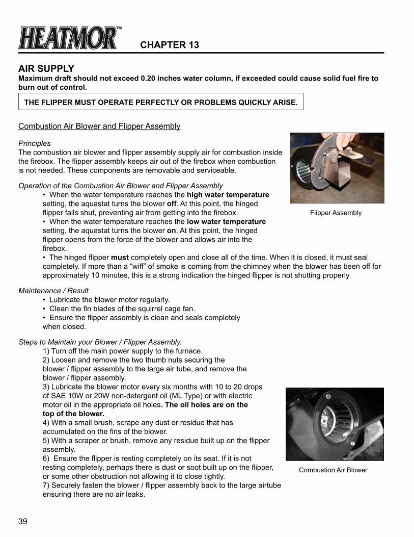
Combustion Air Blower and Flipper Assembly
PrinciplesThe combustion air blower and flipper assembly supply air for combustion inside the firebox. The flipper assembly keeps air out of the firebox when combustion is not needed. These components are removable and serviceable.
Operation of the Combustion Air Blower and Flipper Assembly • When the water temperature reaches the high water temperature setting, the aquastat turns the blower off. At this point, the hinged flipper falls shut, preventing air from getting into the firebox. • When the water temperature reaches the low water temperature setting, the aquastat turns the blower on. At this point, the hinged flipper opens from the force of the blower and allows air into the firebox. • The hinged flipper must completely open and close all of the time. When it is closed, it must seal completely. If more than a “wiff” of smoke is coming from the chimney when the blower has been off for approximately 10 minutes, this is a strong indication the hinged flipper is not shutting properly.
Maintenance / Result • Lubricate the blower motor regularly. • Clean the fin blades of the squirrel cage fan. • Ensure the flipper assembly is clean and seals completely when closed.
Steps to Maintain your Blower / Flipper Assembly. 1) Turn off the main power supply to the furnace. 2) Loosen and remove the two thumb nuts securing the blower / flipper assembly to the large air tube, and remove the blower / flipper assembly. 3) Lubricate the blower motor every six months with 10 to 20 drops of SAE 10W or 20W non-detergent oil (ML Type) or with electric motor oil in the appropriate oil holes. the oil holes are on the top of the blower. 4) With a small brush, scrape any dust or residue that has accumulated on the fins of the blower. 5) With a scraper or brush, remove any residue built up on the flipper assembly. 6) Ensure the flipper is resting completely on its seat. If it is not resting completely, perhaps there is dust or soot built up on the flipper, or some other obstruction not allowing it to close tightly. 7) Securely fasten the blower / flipper assembly back to the large airtube ensuring there are no air leaks.
the FLiPPer Must OPerate PerFectLy Or PrOBLeMs QuicKLy arise.
Flipper Assembly
Combustion Air Blower

40
Removal and Replacement 1) Turn off the main power supply to the furnace and remove the front housing panel. 2) Loosen and remove the thumbnuts securing the blower / flipper assembly to the air tube. 3) Disconnect the electrical wire from the blower. 4) Remove the flipper assembly from the blower by removing the four bolts. This will require a 7/16 inch wrench. 5) Attach the existing flipper assembly to the new blower. 6) Rewire the electrical wire to the blower. contact a licensed electrician if you have any questions. 7) Securely fasten the blower back to the air tube ensuring that there are no air leaks.
the FLiPPer Must OPerate PerFectLy Or PrOBLeMs QuicKLy arise.
If the flipper is unable to open and close freely, or remains partially open or partially closed, the furnace will starve for air resulting in a smoldering fire instead of an intense fire. More smoke and creosote is the result. If the flipper is not operating correctly, it causes a snowball effect of problems. Maintain the FLiPPer!
Air Box
PrincipleThe air box is designed to distribute the appropriate percentage of air from the blower, into different areas of the firepot so the fire will burn efficiently and clean.
Maintenance / ResultCheck for ashes in the air box. If ashes are in the air box, they may interfere with the opening and closing of the flipper. If ashes cover the air outlets, less air will get into the firebox. Be certain the ashes are cold before attempting to remove ashes from the air box. To maintain the air box, remove two nuts on the airbox cleanout cover and clean the ashes out of the air box with a mini-vacuum, brush or your hand. You may need to loosen up hard packed ashes. Securely fasten the airbox cleanout cover back onto the airbox ensuring there are no air leaks.
Removal and Replacement of the airbox 1) Let the unit cool down. 2) Disconnect electrical and turn off breaker. 3) Remove the fan from the airbox 7) Disconnect the auger motor from the auger gear. 8) Disconnect the electrical components from the airbox. 9) Loosen and remove the four bolts from the internal hopper and the airbox. 10) Loosen and remove the four bolts from the back of the firebox and the airbox. 11) Pull the entire airbox and replace 12) Reverse the above.
Air Box
41
chaPter 14
chiMney anD FLue
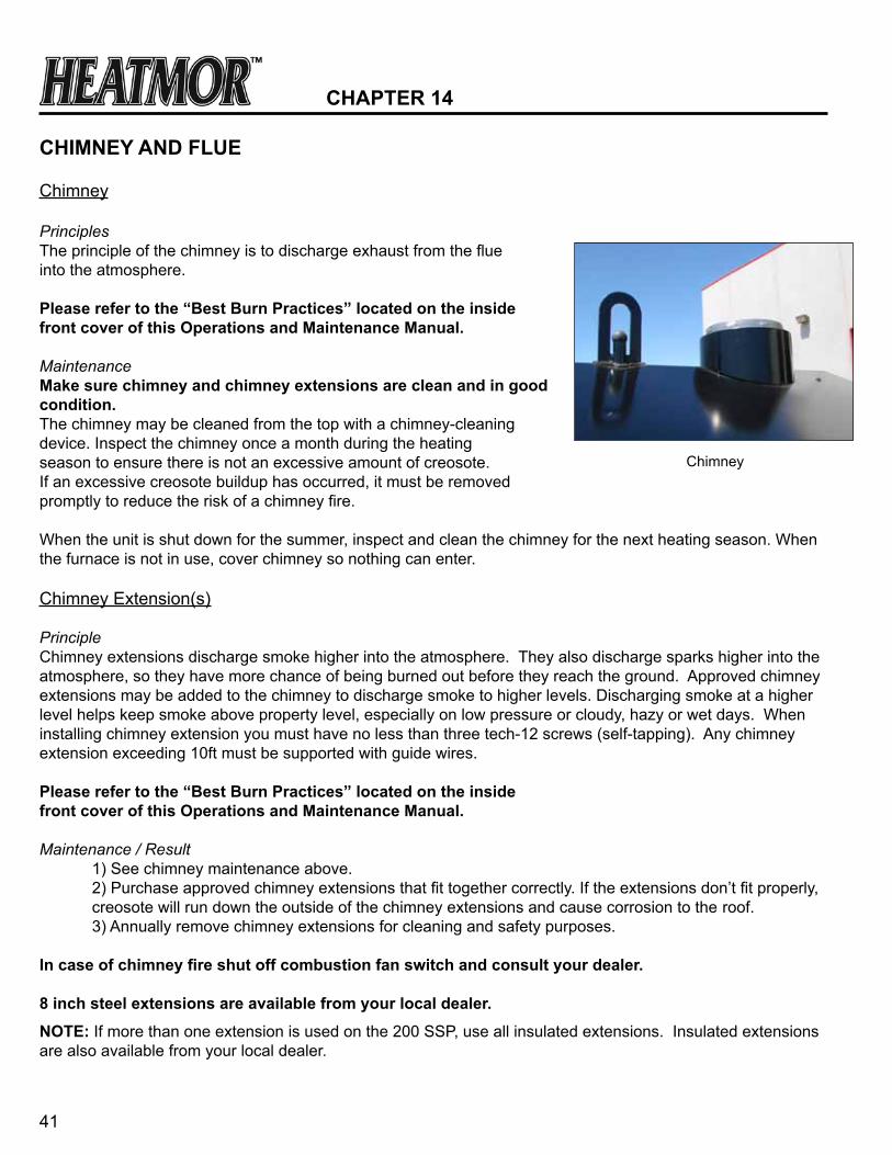
Chimney
PrinciplesThe principle of the chimney is to discharge exhaust from the flue into the atmosphere.
Please refer to the “Best Burn Practices” located on the inside front cover of this Operations and Maintenance Manual.
MaintenanceMake sure chimney and chimney extensions are clean and in good condition.The chimney may be cleaned from the top with a chimney-cleaning device. Inspect the chimney once a month during the heating season to ensure there is not an excessive amount of creosote. If an excessive creosote buildup has occurred, it must be removed promptly to reduce the risk of a chimney fire.
When the unit is shut down for the summer, inspect and clean the chimney for the next heating season. When the furnace is not in use, cover chimney so nothing can enter.
Chimney Extension(s)
PrincipleChimney extensions discharge smoke higher into the atmosphere. They also discharge sparks higher into the atmosphere, so they have more chance of being burned out before they reach the ground. Approved chimney extensions may be added to the chimney to discharge smoke to higher levels. Discharging smoke at a higher level helps keep smoke above property level, especially on low pressure or cloudy, hazy or wet days. When installing chimney extension you must have no less than three tech-12 screws (self-tapping). Any chimney extension exceeding 10ft must be supported with guide wires.
Please refer to the “Best Burn Practices” located on the inside front cover of this Operations and Maintenance Manual.
Maintenance / Result 1) See chimney maintenance above. 2) Purchase approved chimney extensions that fit together correctly. If the extensions don’t fit properly, creosote will run down the outside of the chimney extensions and cause corrosion to the roof. 3) Annually remove chimney extensions for cleaning and safety purposes.
In case of chimney fire shut off combustion fan switch and consult your dealer.
8 inch steel extensions are available from your local dealer.
nOte: If more than one extension is used on the 200 SSP, use all insulated extensions. Insulated extensions are also available from your local dealer.
Chimney
42
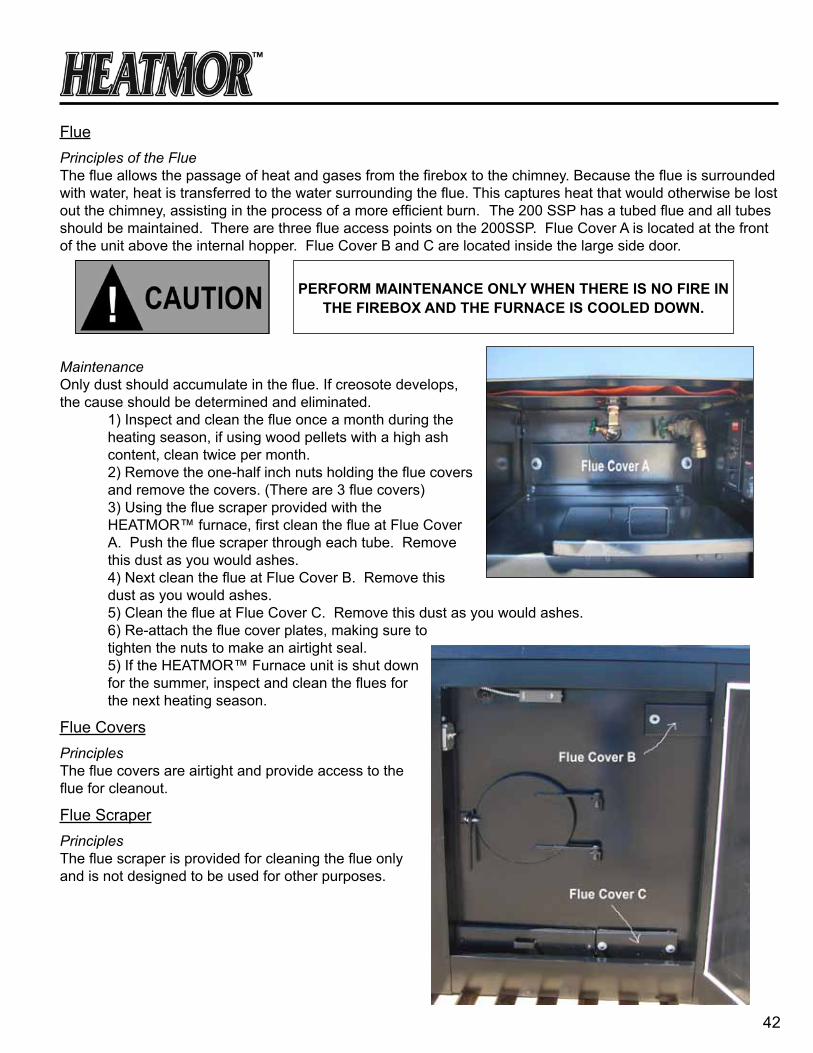
FluePrinciples of the FlueThe flue allows the passage of heat and gases from the firebox to the chimney. Because the flue is surrounded with water, heat is transferred to the water surrounding the flue. This captures heat that would otherwise be lost out the chimney, assisting in the process of a more efficient burn. The 200 SSP has a tubed flue and all tubes should be maintained. There are three flue access points on the 200SSP. Flue Cover A is located at the front of the unit above the internal hopper. Flue Cover B and C are located inside the large side door.
MaintenanceOnly dust should accumulate in the flue. If creosote develops, the cause should be determined and eliminated. 1) Inspect and clean the flue once a month during the heating season, if using wood pellets with a high ash content, clean twice per month. 2) Remove the one-half inch nuts holding the flue covers and remove the covers. (There are 3 flue covers) 3) Using the flue scraper provided with the HEATMOR™ furnace, first clean the flue at Flue Cover A. Push the flue scraper through each tube. Remove this dust as you would ashes. 4) Next clean the flue at Flue Cover B. Remove this dust as you would ashes. 5) Clean the flue at Flue Cover C. Remove this dust as you would ashes. 6) Re-attach the flue cover plates, making sure to tighten the nuts to make an airtight seal. 5) If the HEATMOR™ Furnace unit is shut down for the summer, inspect and clean the flues for the next heating season.
Flue CoversPrinciplesThe flue covers are airtight and provide access to the flue for cleanout.
Flue ScraperPrinciplesThe flue scraper is provided for cleaning the flue onlyand is not designed to be used for other purposes.
PerFOrM Maintenance OnLy When there is nO Fire in the FireBOX anD the Furnace is cOOLeD DOWn.

43
ashes
Disconnect power before removing ashes.
Ash Management and Ash Removal
1) If ash management is deficient, the HEATMOR™ will not perform to its optimum. It is time well spent to ensure proper ash management. In the long run, the operator will be paid back many times over in higher efficiency and better performance. Improper ash management results in one unfavorable condition starting a chain reaction of additional problems. ashes should be removed before the ash pan is completely full.
2) You do not need to allow the wood pellets in the firepot to burn out to remove the ashes, the ashes will drop into the ashpan below the firepot automatically as the wood burns into ashes. When all fuel has been burned out of the ashes, they will be a gray and black color and very light. If some unburnt pellets are in the ashpan, adjust the auger feed setting see “Loading Wood Pellets into the Heatmor”
3) It is not necessary to rake or move the ashes in the firepot. They will naturally flow into the ash pan as new pellets are augered into the firepot and the ash is light enough to be blown out of the firepot. 4) it is recommended to remove ashes once per day. Choose a time of day and faithfully do the ash removal chore on that same time, every day.
5) a particle mask, gloves and protective equipment should be worn when removing ashes.
6) When removing ashes using the integrated ash pan, immediately dispose of the ashes into a larger, sealed, metal container. Replace the ash pan under the firepot in the firebox after each use. handle the ash pan with care as it will be very hot. Be sure to seal the ash pan door after each use, making an airtight seal. You may need to remove ashes from under the firebox when the ash pan is not in place; if you need to do this it may help to remove the lower housing panel and place the ash pan under the opening.
7) Removed ashes should be stored in a steel container, sealed with a steel tight fitting lid, and placed in an area free of combustible materials for a few days, to allow the ashes to completely cool before being disposed. Ash Pan
PrinciplesThe ash pan is a storage reservoir for completely burned ashes. A reasonable amount of ashes (two to four gallons) should be removed during each ash removal. The ash pan is replaceable. handle the ash pan with care as it will be very hot.
Removal and Replacement of the ash pan 1) Let the unit cool down. 2) Disconnect electrical and turn off breaker. 3) Remove the ash pan from the firebox and replace. 4) Reverse the above.
chaPter 15

44
Ash Pan Cover Plate
PrinciplesThe ash pan cover plate is a rectangular plate that is secured over the ash pan opening, creating an airtight seal.
200 SSP Operation 1) When removing ashes, always turn off combustion air blower and disconnect power. 2) Remove the two thumb nuts. 3) Pull out the ash pan and remove the ashes. 4) Replace the ash pan and cover plate and securely tighten the two thumb nuts.
Creosote
Creosote - Formation and Need for Removal
When wood is burned slowly, it produces tar and other organic vapors, which combine with expelled moisture to form creosote. The creosote vapors condence in the relatively cool chimney flue of a slow burning fire. As a result, creosote residue accumulates on the flue lining. When ignited this creosote makes an extremely hot fire.
The chimney connector and chimney should be inspected at least twice monthly during the heating season to determine if a creosote build up has occured.
Also check daily for creosote build up until experience shows how often cleaning is necessary.
Be aware that the hotter the fire, the less creosote is deposited, and that weekly cleanings can be necessary in mild weather, even though monthly cleanings can be enough in the colest months.
If creosote has accumulated it should be removed to reduce the risk of a chimney fire.
Do not connect this unit to the chimney flue serving another appliance.
Ash Pan and Ash Pan Cover plate

45
eLectricaL
PrinciplesThe HEATMORTM furnace comes with all internal components pre-wired. Provision is made for easy attachment of the main electrical power supply to the HEATMOR™ controls. Electrical outlets at the rear of the HEATMOR™ accommodate plugging in circulating pumps.
Electrical Supply
have a licensed electrician make all electrical connections.Required electrical power supply to the HEATMOR™ is 115 volts, 60HZ, 1 phase.
1) Use only 14/3 electrical wire. 2) The 14/3 wire will actually contain 4 wires; a) black, b) white, c) red, d) ground 3) If the electrical wire is being buried in the trench, be certain to use electrical wire approved for direct burial. 4) Do not place electrical wire in close contact with the supply and return lines. 5) The electrical supply wire should be connected to it’s own circuit.
Electrical Supply Junction Box
PrinciplesThe electrical components of the HEATMOR™ furnace are pre-wired at the factory. All the wiring becomes centralized in the junction box.
Connecting the main power supply to the HEATMOR™: 1) Remove the plate on the Electrical Supply Junction Box. 2) Insert the electrical supply wire through the electrical connector on the electrical supply junction box. 3) The black wires are connected, the white wires are connected, the ground wires are connected, and the red wires are connected. 4) Tighten the screw clamp in the electrical connector to hold the supply wire firm. 5) Replace the plate on the Electrical Supply Junction Box.
Maintenance • Keep the junction box clean and dry. • Keep the cover plate firmly attached at all times. • Make certain the MARR connectors (wire nuts) are properly installed and holding tight.
chaPter 16
Electrical Supply Junction Box
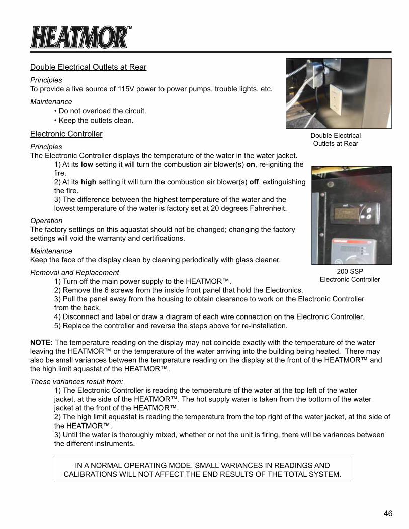
46
Double Electrical Outlets at RearPrinciplesTo provide a live source of 115V power to power pumps, trouble lights, etc.
Maintenance • Do not overload the circuit. • Keep the outlets clean.
Electronic ControllerPrinciplesThe Electronic Controller displays the temperature of the water in the water jacket. 1) At its low setting it will turn the combustion air blower(s) on, re-igniting the fire. 2) At its high setting it will turn the combustion air blower(s) off, extinguishing the fire. 3) The difference between the highest temperature of the water and the lowest temperature of the water is factory set at 20 degrees Fahrenheit. Operation The factory settings on this aquastat should not be changed; changing the factory settings will void the warranty and certifications.
MaintenanceKeep the face of the display clean by cleaning periodically with glass cleaner.
Removal and Replacement 1) Turn off the main power supply to the HEATMOR™. 2) Remove the 6 screws from the inside front panel that hold the Electronics. 3) Pull the panel away from the housing to obtain clearance to work on the Electronic Controller from the back. 4) Disconnect and label or draw a diagram of each wire connection on the Electronic Controller. 5) Replace the controller and reverse the steps above for re-installation.
nOte: The temperature reading on the display may not coincide exactly with the temperature of the water leaving the HEATMOR™ or the temperature of the water arriving into the building being heated. There may also be small variances between the temperature reading on the display at the front of the HEATMOR™ and the high limit aquastat of the HEATMOR™.
These variances result from: 1) The Electronic Controller is reading the temperature of the water at the top left of the water jacket, at the side of the HEATMOR™. The hot supply water is taken from the bottom of the water jacket at the front of the HEATMOR™. 2) The high limit aquastat is reading the temperature from the top right of the water jacket, at the side of the HEATMOR™. 3) Until the water is thoroughly mixed, whether or not the unit is firing, there will be variances between the different instruments.
Double Electrical Outlets at Rear
IN A NORMAL OPERATING MODE, SMALL VARIANCES IN READINGS AND CALIBRATIONS WILL NOT AFFECT THE END RESULTS OF THE TOTAL SYSTEM.
200 SSPElectronic Controller

47
Electronic Controller Temperature ProbePrinciplesThe temperature probe is how the Electronic Controller reads the temperature of the water in the water jacket.
Removal and Replacement 1) Turn off the main power supply to the HEATMOR™. 2) Remove the 6 screws from the inside front panel that hold the Electronics. 3) Pull the panel away from the housing to obtain clearance to disconnect the temperature probe from the electronic controller. 4) Pull the temperature probe out of the well and disconnect from the electronic controller. 5) Install the new temperature probe wires into the electronic controller and install the probe into the well. 6) Replace the Electronics panel.
Watlow Flame Sensor ControlPrinciplesThe Watlow Flame Sensor Control is a safety feature to prevent adding fuel to the firepot when it is not wanted. 1) Below its temperature setting it will not allow the auger to feed pellets into the firepot.
Operation The factory setting on this flame sensor is 200oF. For ignition, you should turn this setting down for only a short time period to allow ignition then return its setting to 200oF for safety. See “Lighting the HEATMOR™ for the First Time”.
Removal and Replacement 1) Turn off the main power supply to the HEATMOR™. 2) Remove the 6 screws from the inside front panel that hold the Electronics. 3) Pull the panel away from the housing to obtain clearance to work on the Watlow Flame Sensor Control from the back. 4) Disconnect and label or draw a diagram of each wire connection on the Watlow Flame Sensor. 5) Replace the Flame Sensor and reverse the steps above for re-installation.
Electronic Controller Temperature Probe
Watlow Flame Sensor Control
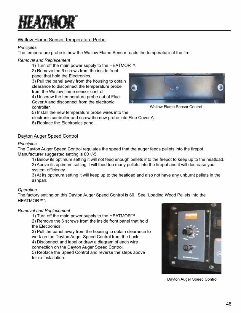
48
Watlow Flame Sensor Temperature ProbePrinciplesThe temperature probe is how the Watlow Flame Sensor reads the temperature of the fire.
Removal and Replacement 1) Turn off the main power supply to the HEATMOR™. 2) Remove the 6 screws from the inside front panel that hold the Electronics. 3) Pull the panel away from the housing to obtain clearance to disconnect the temperature probe from the Watlow flame sensor control. 4) Unscrew the temperature probe out of Flue Cover A and disconnect from the electronic controller. 5) Install the new temperature probe wires into the electronic controller and screw the new probe into Flue Cover A. 6) Replace the Electronics panel.
Dayton Auger Speed ControlPrinciplesThe Dayton Auger Speed Control regulates the speed that the auger feeds pellets into the firepot. Manufacturer suggested setting is 80+/-5. 1) Below its optimum setting it will not feed enough pellets into the firepot to keep up to the heatload. 2) Above its optimum setting it will feed too many pellets into the firepot and it will decrease your system efficiency. 3) At its optimum setting it will keep up to the heatload and also not have any unburnt pellets in the ashpan.
Operation The factory setting on this Dayton Auger Speed Control is 80. See “Loading Wood Pellets into the HEATMOR™”.
Removal and Replacement 1) Turn off the main power supply to the HEATMOR™. 2) Remove the 6 screws from the inside front panel that hold the Electronics. 3) Pull the panel away from the housing to obtain clearance to work on the Dayton Auger Speed Control from the back. 4) Disconnect and label or draw a diagram of each wire connection on the Dayton Auger Speed Control. 5) Replace the Speed Control and reverse the steps above for re-installation.
Watlow Flame Sensor Control
Dayton Auger Speed Control

49
High Water Temperature Safety Shutoff Control (High-Limit) PrinciplesThe correct name is an “aquastat.” It is referred to as an aquastat because it measures the temperature of water (aqua means water). It is sometimes referred to as a thermostat, but thermo means air. It does not measure the temperature of air. The High Water Temperature Safety Shutoff Control turns off all electrical power to the combustion air blower and the front light if an excessive water temperature be reached. To provide added safety and notification, when a high water temperature is reached, this aquastat will send electrical power to the “red wire”. The red wire leading from the HEATMOR™ back to the power source can be installed so the electrical power will sound an alarm or will override the comfortable heat settings within the heated building. By starting heating appliances in the building, heat will be drawn off the HEATMOR™, dumped into the building, creating an elevated temperature environment in the building, and hence a notification of an unusually high water temperature within the HEATMOR™. By removing this excess heat from the HEATMOR™, a “boil” will normally be avoided.
Operation • From the factory, this control is set at 200 degrees Fahrenheit. When the water temperature within the water jacket lowers to 195 degrees Fahrenheit; the electrical circuit to the main combustion air blower(s) would be re-activated. The combustion air blower will not come back on until the low water temperature is reached. • DO nOt MaKe any aDJustMents. Leave it set at 200 degrees Fahrenheit.
Removal and Replacement 1) Turn off the main power supply to the HEATMOR™. 2) Remove the aquastat cover. 3) Disconnect and label or draw a diagram of each wire connection on the aquastat. 4) Loosen the two screws at the back of the aquastat, which clamp the aquastat to the “well” in the water jacket. 5) Pull the aquastat body straight out of the “well”, ensuring the copper wire and probe is being pulled out of the well along with the body. 6) Insert the new unit probe first into the well. (Ensure contact paste has been applied to well.) 7) The clamp must fit around the groove of the well. Tighten the clamp with the two screws at the back of the aquastat body. 8) Connect the electrical wires to the appropriate connections, following the label or diagram. 9) Replace the cover. 10) Turn on the power. 11) Adjust the dial and white wheel to the preferred settings.
High Water Temperature Safety Shutoff Control

50
iF the Water teMPerature is high enOugh tO trigger the high Water teMPerature saFety shutOFF,
the FrOnt Light WiLL nOt turn On When the Fan POWer sWitch is in the DOWn POsitiOn.
Front Light and Fan Power SwitchPrinciples 1) To provide light while fueling. 2) To provide a means of turning off the combustion air blower on demand. 3) To provide a visual warning that electrical power to the combustion air blower has been terminated.
Operation of the Front Light and Fan Power Switch • By adjusting the fan power switch to the down position, the electrical power to the combustion air blower is manually terminated, and the front light turns on. • This light will then illuminate the area in front of the HEATMOR™. • The light must be turned off for electrical power to be running to the combustion air blower.
Removal and Replacement of the Front Light Bulb 1) Remove the glass globe by first loosening the setscrew and then unscrew the globe. 2) Replace the light bulb. 3) Replace the globe and tighten the setscrew.
Removal and Replacement of the Fan Power/Light Switch 1) Turn off the main electrical power supply to the HEATMOR™. 2) Remove the switch cover plate. 3) Make a sketch of the location of the wires on the switch. 4) Remove the wires, and replace the switch. This is a special 3-way switch. 5) Replace the wires as in the diagram. 6) Secure the cover plate. 7) Turn the main electrical power supply back on to the HEATMOR™.
note: it is recommended to contact a licensed electrician to perform the above operation.
Front Light
Front Light and Fan Power Switch (left switch)
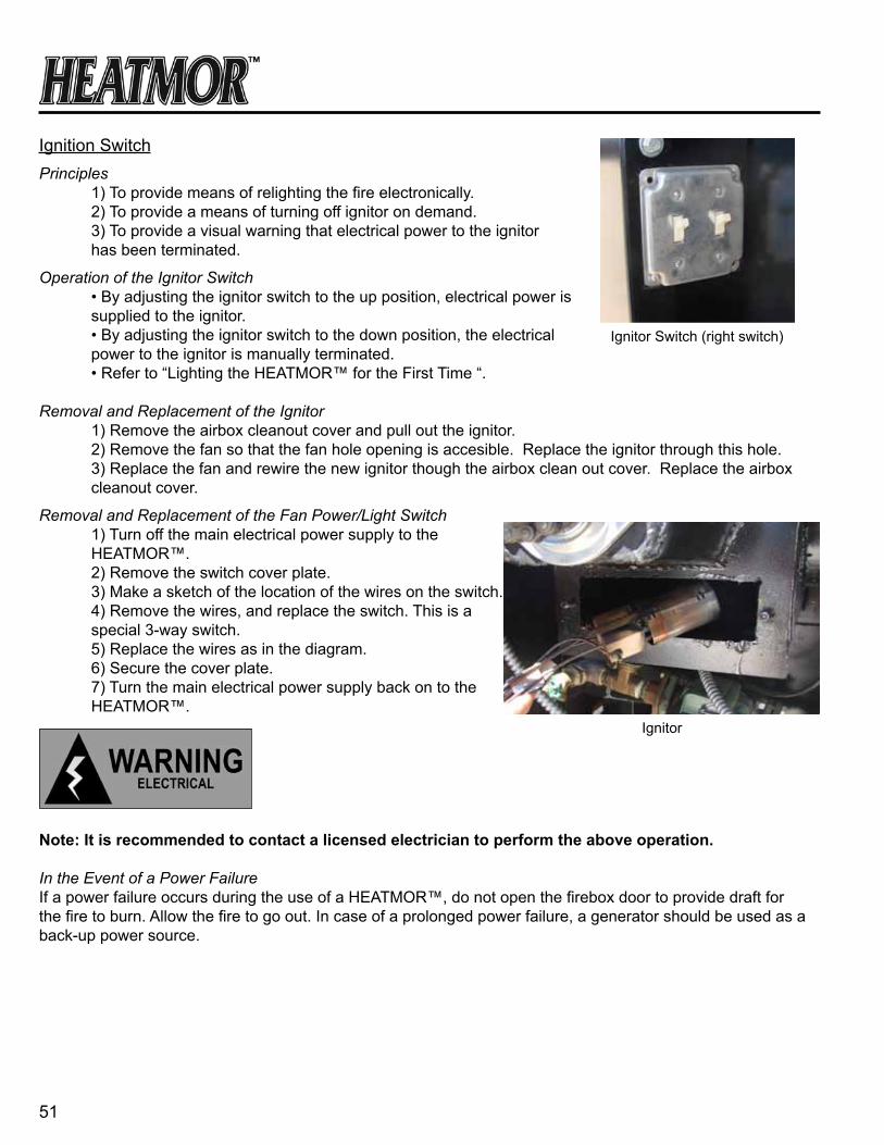
51
Ignition SwitchPrinciples 1) To provide means of relighting the fire electronically. 2) To provide a means of turning off ignitor on demand. 3) To provide a visual warning that electrical power to the ignitor has been terminated.
Operation of the Ignitor Switch • By adjusting the ignitor switch to the up position, electrical power is supplied to the ignitor. • By adjusting the ignitor switch to the down position, the electrical power to the ignitor is manually terminated. • Refer to “Lighting the HEATMOR™ for the First Time “.
Removal and Replacement of the Ignitor 1) Remove the airbox cleanout cover and pull out the ignitor. 2) Remove the fan so that the fan hole opening is accesible. Replace the ignitor through this hole. 3) Replace the fan and rewire the new ignitor though the airbox clean out cover. Replace the airbox cleanout cover.
Removal and Replacement of the Fan Power/Light Switch 1) Turn off the main electrical power supply to the HEATMOR™. 2) Remove the switch cover plate. 3) Make a sketch of the location of the wires on the switch. 4) Remove the wires, and replace the switch. This is a special 3-way switch. 5) Replace the wires as in the diagram. 6) Secure the cover plate. 7) Turn the main electrical power supply back on to the HEATMOR™.
note: it is recommended to contact a licensed electrician to perform the above operation.
In the Event of a Power FailureIf a power failure occurs during the use of a HEATMOR™, do not open the firebox door to provide draft for the fire to burn. Allow the fire to go out. In case of a prolonged power failure, a generator should be used as a back-up power source.
Ignitor Switch (right switch)
Ignitor

52
chaPter 17
PeLLet suPPLy
Internal Hopper of the HEATMOR™
Principle of the Internal HopperThe internal hopper provides a location to store pellets away from the outside elements. The internal hopper holds approx. 4 bags of wood pellets.
Operation of the Internal HopperThe internal hopper has a hinged door to provide a place to pourthe wood pellets into the hopper. The hopper door should always be closed securely to prevent unwanted “burn back” of pellets.
Maintenance / ResultKeep the internal hopper door free from any obstruction and ensure door seals against the doorframe. This wil keep air from entering the hopper and preventing “burn back” of pellets.
Removal and ReplacementIf the hopper has been damaged, it can be replaced with new hopper. Contact your local dealer.
Auger and Auger Motor
Principle of the Auger SystemThe auger system provides the automatic feed of the wood pelletsinto the firepot.
Operation of the Auger SystemThe auger motor turns the chain which turns the auger and augerswood pellets from the hopper to the firepot. The speed setting on the motor can be set to auger pellets quickly or slowly by the Dayton Auger Speed Control.
Maintenance / ResultKeep the auger system free from any obstruction and always keep the back panel in place to protect the auger system from outside elements. Spray oil on the chain once a month.
Removal and ReplacementIf any part of the auger system has been damaged, it can be replaced. Contact your local dealer.
Internal Hopper
Auger and Auger Motor

53
eXteriOr cLaDDing anD insuLatiOn
Outer Front and Side Doors of the HEATMOR™
Principles of the Outer Front and Side DoorsThe outer doors of the furnace are exterior doors, which areinsulated to retain the heat that radiates from the firebox door and water jacket surface. The doors provides lockable,protective surfaces to prevent any hot surface from being exposed.
Operation of the Outer Front and Side DoorsThe outer doors are hinged and open to the right of the furnace. A keyed lock is installed on the left side of each of the doors, providing an easy way to ensure the doors cannot be opened allowing untrained users to be injured.
Maintenance / ResultKeep the doors free from any obstruction and ensure that the inner seal of the door seals against the doorframe. This wil keep cold air from entering the heated air cavity, which provides the air box and firebox with air.
Removal and ReplacementTo remove the outer door, the lock handle must be unlocked and opened. The doors rest on pinned hinges on the right side, simply lift up squarely on the door to remove it. Place and secure the new door into position on the hinges. Test the door to ensure a tight seal to the doorframe of the furnace.
Roof of the HEATMOR™
Principle of the RoofThe roof of the furnace is one solid piece of roofing steel creased in the center. This provides a dry covering to protectthe insulation of the furnace.
Maintenance / ResultInspect the roof of the furnace once a year to verify that none of the roof screws have broken. A large number of broken roof screws can allow damage to the furnace roof. Ensure the lift hook and chimney are sealed so no water can enter into the roof insulation.
Removal and ReplacementIf the roof has been damaged it can be replaced by a matching roof. Follow these steps or contact your local dealer.
chaPter 18
Front Door
Side Door
Door Lock
aBsOLuteLy nO Fire in the FireBOX When PerFOrMing this rePair. DO nOt PerFOrM this rePair When unit
Water teMPerature is unsaFe. aLWays Wear PrOPer PersOnaL PrOtective eQuiPMent.
Roof

54
1) Remove the silicone from around the lift hook and relief vent pipe. 2) Remove all roof screws holding the damaged roof secure. 3) Lift the old roof steel off the furnace. 4) Install the new roof steel. 5) Secure the new roof to the frame of the furnace. 6) Re-seal the lift point and relief vent pipe with caulking.
Sides of the HEATMOR™
Principle of the Sides and EndsThe sides of the furnace are clad with black steel. The steel siding provides a dry covering to protect the insulation of the furnace. The left side of the furnace has an external hopper hook-up access door.
Maintenance / ResultInspect the sides of the furnace once a year to verify that there is no damage. Ensure there is a good seal so no water can enter into the insulation covering the sides of the water jacket.
Removal and ReplacementIf the sides have been damaged they can be replaced with new paneled steel siding. Contact your local dealer.
Insulation
Principle of the InsulationThe insulation helps retain the heat in the water, which has been heated by the fire. It also provides a heat barrier to ensure that the outer steel siding does not resease any heat.
Maintenance / ResultIt is important to keep the insulation dry. Wet insulation loses its R-Value. Keep the base of the furnace sealed to prevent small rodents from making nests or wrecking the insulation.
Removal and ReplacementTo remove and replace the insulation, please contact your local dealer.
Side
Insulation
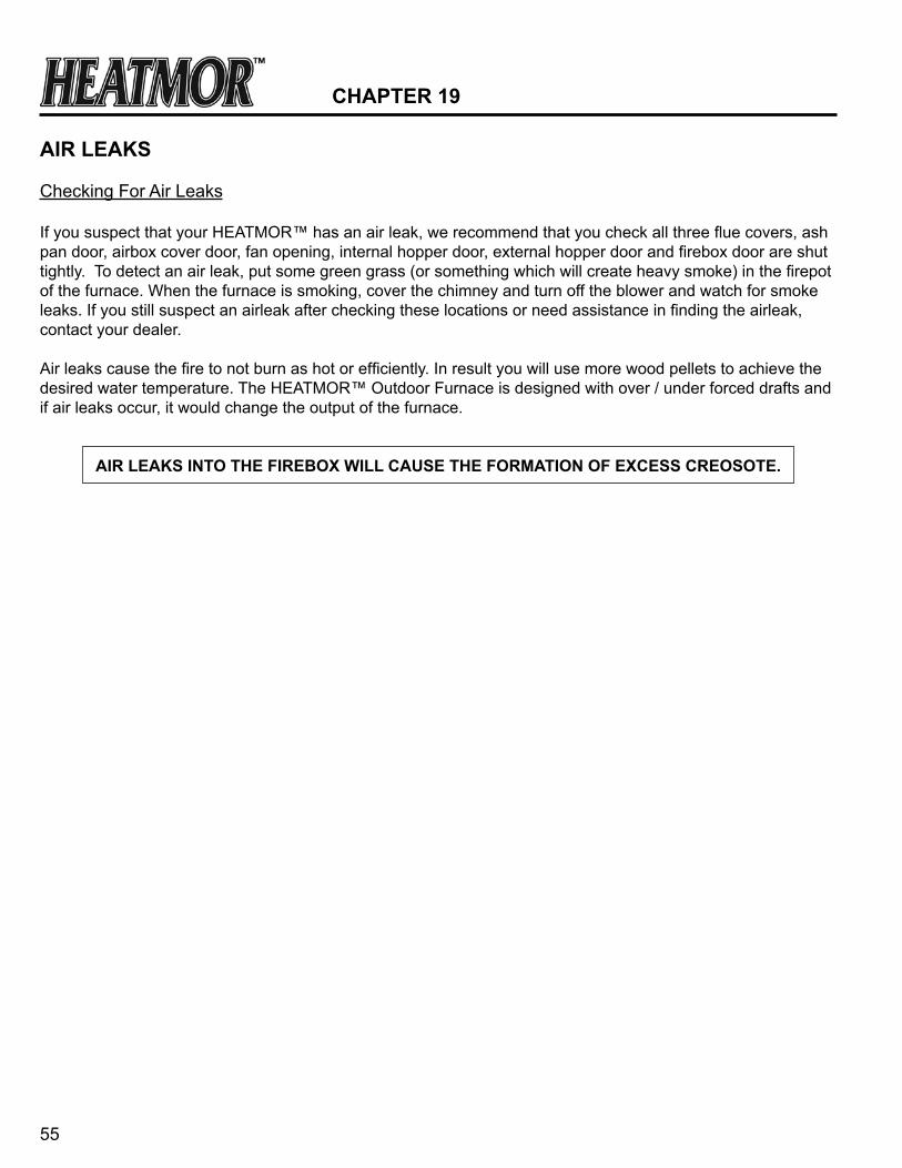
55
chaPter 19
air LeaKs
Checking For Air Leaks
If you suspect that your HEATMOR™ has an air leak, we recommend that you check all three flue covers, ash pan door, airbox cover door, fan opening, internal hopper door, external hopper door and firebox door are shut tightly. To detect an air leak, put some green grass (or something which will create heavy smoke) in the firepot of the furnace. When the furnace is smoking, cover the chimney and turn off the blower and watch for smoke leaks. If you still suspect an airleak after checking these locations or need assistance in finding the airleak, contact your dealer.
Air leaks cause the fire to not burn as hot or efficiently. In result you will use more wood pellets to achieve the desired water temperature. The HEATMOR™ Outdoor Furnace is designed with over / under forced drafts and if air leaks occur, it would change the output of the furnace.
air LeaKs intO the FireBOX WiLL cause the FOrMatiOn OF eXcess creOsOte.

56
Water LeaKs
If you suspect that your HEATMOR™ Stainless Steel Outdoor Furnace has developed a water leak, please contact your local dealer for verification and further details.
chaPter 20
57
seasOn start-uP Maintenance checKList To begin season start-up of your Heatmor Outdoor Furnace, assuming you followed the procedures outlined in the “End of Season Maintenance Checklist,” follow the instructions below:
1. Remove cap from chimney. 2. Build fire in firepot and bring your furnace up to temperature. (Refer to the “Lighting the HeatmorTM for the first time” section of the HeatmorTM Operations and Maintenance Manual.)
3. Once your furnace is up to temperature, you can start all pumps. cautiOn: It is recommended to start your pumps AFTER you bring your furnace up to temperature. This helps ensure your system isn’t air locked and ensure your water is circuating correctly. 4. Your start-up is complete.
enD OF seasOn Maintenance checKList To begin End of Season Shutdown of your Heatmor™ Outdoor Furnace, follow the instructions below:
1. Turn off pump(s). 2. Clean Flue (Refer to the “Flue” section of the HeatmorTM Operations and Maintenance Manual.) a) Remove Flue Covers b) Using the flue scrapers provided with the HEATMOR™ furnace clean all areas of the flue. c) Re-attach the flue cover plates, making sure to tighten the nuts to make an airtight seal.
3. Clean ashes out of Firebox. (Refer to the “Ashes” section of the HeatmorTM Operations and Maintenance Manual.) a) Thoroughly pull ashes from sides and corners of Firebox. 4. Clean ashes out of Ash Pan. (Refer to the “Ashes” section of the HeatmorTM Operations and Maintenance Manual.) 5. Place cap on Chimney. There is no specific product sold for this use, but a five gallon bucket or something similar will cover the chimney keeping unwanted moisture and visitors away.
6. Spray oil on the auger chain.
chaPter 21

58
7. Properly clean and oil Fan. (Refer to the “Air Supply” section of the HeatmorTM Operations and Maintenance Manual.) 1) Turn off the main power supply to the furnace. 2) Loosen and remove the two thumb nuts securing the blower / flipper assembly to the large air tube, and remove the blower / flipper assembly. 3) Lubricate the blower motor every six months with 10 to 20 drops of SAE 10W or 20W non-detergent oil (ML Type) or with electric motor oil in the appropriate oil holes. the oil holes are on the bottom of the blower. 4) With a small brush, scrape any dust or residue that has accumulated on the fins of the blower. 5) With a scraper or brush, remove any residue built up on the flipper assembly. 6) Ensure the flipper is resting completely on its seat. If it is not resting completely, perhaps there is dust or soot built up on the flipper, or some other obstruction not allowing it to close tightly. 7) Securely fasten the blower / flipper assembly back to the large air tube ensuring there are no air leaks.
8. Check PH level of your system water. Your PH level should be between 8 - 10. (Refer to the “Water” section in the Heatmor™ Operations and Maintenance Manual.)
The water in the HEATMOR™ should be chemically analyzed once per year to ensure the proper levels of treatment are being maintained. Contact your local dealer as to where to have your water
tested. Provide the testing person with an amount of water from your HEATMOR™, equal to approximately 20 ounces, in a clean container. The amount of water treatment that has to be added yearly is dependent on how much fresh water you have added to your system since the last test.
Be certain to add a water treatment that is approved by your dealer and HEATMOR™ Inc.
nOte: To keep the CLT - 545 (water chemical) circulated and properly coated throughout the HEATMOR™ system, it is recommended to start pumps at least once a month for approximately 2 - 3 hours.
cautiOn: It is recommended to start your pumps AFTER you bring your furnace up to temperature. This
helps ensure your system isn’t air locked and ensure your water is circulating correctly.

59
FreQuentLy asKeD QuestiOns
1. Q. How much water should be in the bladder?
a. When the furnace is initially filled, there should be about one inch of water in the bladder with the water at a temperature of 50 degrees Fahrenheit. When the furnace is at its operating temperature, the bladder should be near full but not hard. Overfilling the bladder can shorten the life of the bladder.
Refer to: • Maintaining the correct amount of water in the bladder and in the HEATMOR™.
2. Q. Why is water coming out of the overflow relief vent pipe?
a. When the furnace is initially filled and too much water is in the furnace, it releases through the relief vent pipe when the furnace is up to temperature. If this happens, a small amount of water should be removed from the furnace so the bladder is not hard.
Refer to: • Installation of the HEATMOR™ Furnace.
3. Q. Why is my furnace wet on the inside of the firebox?
a. When your furnace is first fired up, and also at times during normal operation, the atmosphere inside the firebox will exceed the dew point causing condensation.
Refer to: •Furnace has excessive moisture in firebox (Located in Trouble Shooting and Solutions). •Dew Point (Located in Safe Operating Guidelines).
4. Q. Why does my furnace fail to respond to the switch at the front of the furnace? For example; the light will not come on and the fan will not operate?
a. The high limit aquastat has probably overridden the operating aquastat. If this has happened, it should also trigger your distribution system or high water temperature warning.
Refer to: • High Water Temperature Safety Shutoff Controller (Located in Electrical). 5. Q. Why is it getting so warm in my house and I cannot reduce the temperature with the thermostat?
a. At this point the high limit aquastat has been tripped on. To detect the precise reason, please contact your local dealer.
Refer to: • High Water Temperature Safety Shutoff Controller (Located in Electrical).
chaPter 22

60
6. Q. My furnace is shut down but still continues to increase in water temperature?
a. There is an air leak somewhere in the furnace. Check all flippers and seals, ensuring that there is an airtight seal.
Refer to: • Checking for air leaks (Located in Air Leaks).
7. Q. Why am I experiencing an excess build up of creosote in the furnace?
a. You more than likely are introducing unwanted draft into the firebox. This may be caused by several things, including a door ajar, ash cover loose, or flipper assembly stuck. If your furnace is in a location where wind may effect the pressure differential across the furnace, it could cause draft to leak past the flipper.
Refer to: • Creosote Build-up (Located in Trouble Shooting and Solutions).
8. Q. My furnace combustion blower continues to run but the fire will not burn until I open the door?
a. Your flipper assembly is most likely stuck closed. Please refer to the combustion blower, flipper assembly section in the manual for further details or contact your local dealer.
Refer to: • Combustion Air Blower and Flipper Assembly (Located in Air Supply).
9. Q. Water is coming out of the rectangular top chimney flue?
a. Similar to the firebox, when your furnace is initially fired up and also at times during normal operation, the atmosphere inside the firebox and chimney flue will exceed the dew point causing condensation.
Refer to: • Furnace has excessive moisture in firebox (Located in Trouble Shooting and Solutions) • Dew Point (Located in Safe Operating Guidelines).
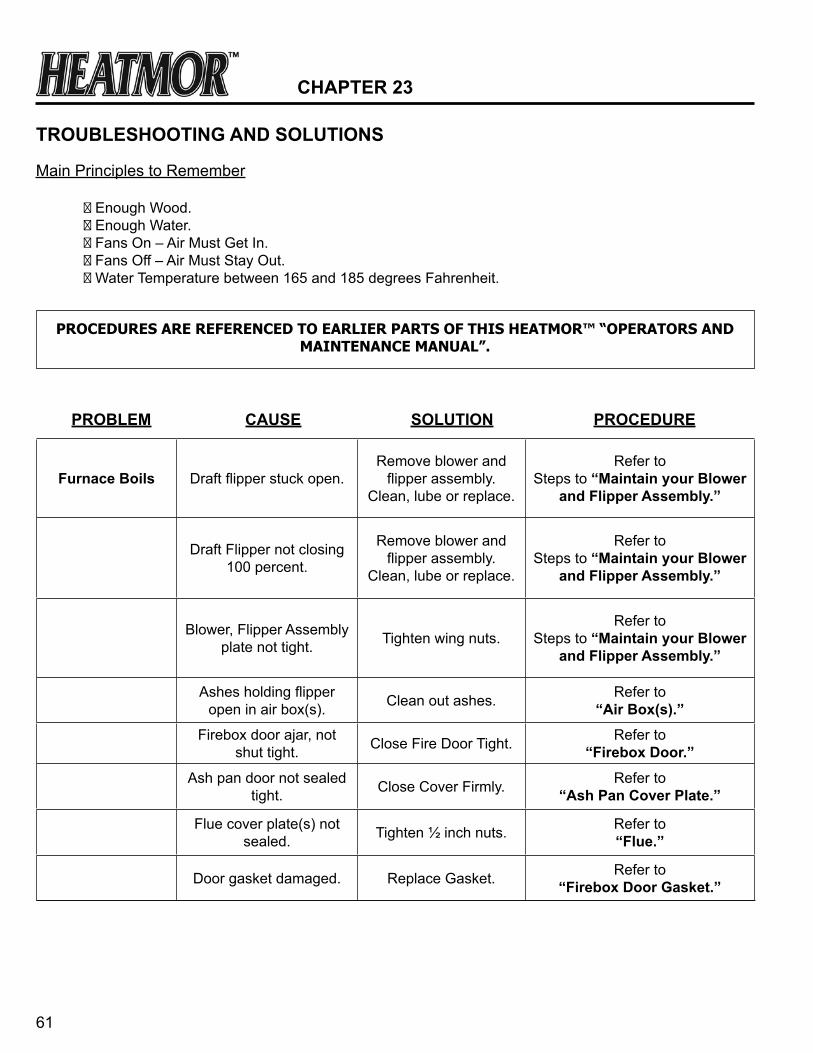
61
chaPter 23
trOuBLeshOOting anD sOLutiOns
Main Principles to Remember ♦ Enough Wood. ♦ Enough Water. ♦ Fans On – Air Must Get In. ♦ Fans Off – Air Must Stay Out. ♦ Water Temperature between 165 and 185 degrees Fahrenheit.
PROCEDURES ARE REFERENCED TO EARLIER PARTS OF THIS HEATMOR™ “OPERATORS AND MAINTENANCE MANUAL”.
PrOBLeM cause sOLutiOn PrOceDure
Furnace Boils Draft flipper stuck open.Remove blower and
flipper assembly. Clean, lube or replace.
Refer to Steps to “Maintain your Blower
and Flipper assembly.”
Draft Flipper not closing 100 percent.
Remove blower and flipper assembly.
Clean, lube or replace.
Refer to Steps to “Maintain your Blower
and Flipper assembly.”
Blower, Flipper Assembly plate not tight. Tighten wing nuts.
Refer to Steps to “Maintain your Blower
and Flipper assembly.”
Ashes holding flipper open in air box(s). Clean out ashes. Refer to
“air Box(s).”Firebox door ajar, not
shut tight. Close Fire Door Tight. Refer to “Firebox Door.”
Ash pan door not sealed tight. Close Cover Firmly. Refer to
“ash Pan cover Plate.”
Flue cover plate(s) not sealed. Tighten ½ inch nuts. Refer to
“Flue.”
Door gasket damaged. Replace Gasket. Refer to “Firebox Door gasket.”
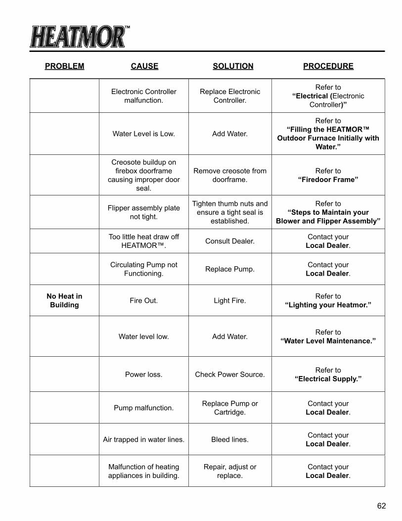
62
Electronic Controller malfunction.
Replace Electronic Controller.
Refer to“electrical (Electronic
Controller)”
Water Level is Low. Add Water.
Refer to“Filling the heatMOr™
Outdoor Furnace initially with Water.”
Creosote buildup on firebox doorframe
causing improper door seal.
Remove creosote from doorframe.
Refer to“Firedoor Frame”
Flipper assembly plate not tight.
Tighten thumb nuts andensure a tight seal is
established.
Refer to“steps to Maintain your
Blower and Flipper assembly”
Too little heat draw off HEATMOR™. Consult Dealer. Contact your
Local Dealer.
Circulating Pump not Functioning. Replace Pump. Contact your
Local Dealer.
no heat in Building Fire Out. Light Fire. Refer to
“Lighting your heatmor.”
Water level low. Add Water. Refer to“Water Level Maintenance.”
Power loss. Check Power Source. Refer to “electrical supply.”
Pump malfunction. Replace Pump or Cartridge.
Contact yourLocal Dealer.
Air trapped in water lines. Bleed lines. Contact yourLocal Dealer.
Malfunction of heatingappliances in building.
Repair, adjust orreplace.
Contact yourLocal Dealer.
PrOBLeM cause sOLutiOn PrOceDure

63
Furnace will not burn properly
or will not maintain water temperature.
Chimney plugged. Clean Chimney. Refer to “chimney stub.”
Not enough wood pellets in hopper. Add wood pellets.
Refer to“Loading wood pellets into the
heatMOr™.”
Poor quality wood pellets. Better wood pellets. Refer to “What can i Burn”
Draft flipper stuck. Remove blower and flipper assembly-clean,
lube or replace.
Refer to “steps to Maintain your
Blower and Flipper assembly.”
Electrical power is off or not constant.
Check all electrical connections. Call dealer or licensed
electrician.
Refer to “electrical (contact Local
Dealer).”
Fire is out. Re-light fire. Refer to “Lighting your heatMOr™.”
Flue plugged. Clean Flue. Refer to “Flue.”
Blower fins are full of dust. Clean Blowers.
Refer to “steps to Maintain your
Blower and Flipper assembly.”
Blowers not running properly or up to speed. Clean Blowers.
Refer to “steps to Maintain your
Blower and Flipper assembly.”
Ashes in Air Box(s). Clean Air Box(s). Refer to air Box(s).
Too many ashes in Firebox restricting air
flow.Clean out ashes.
Refer to “ash Management and ash
removal.”
Auger Speed too low Increase Auger Speed refer to “Dayton auger speed control”
PrOBLeM cause sOLutiOn PrOceDure
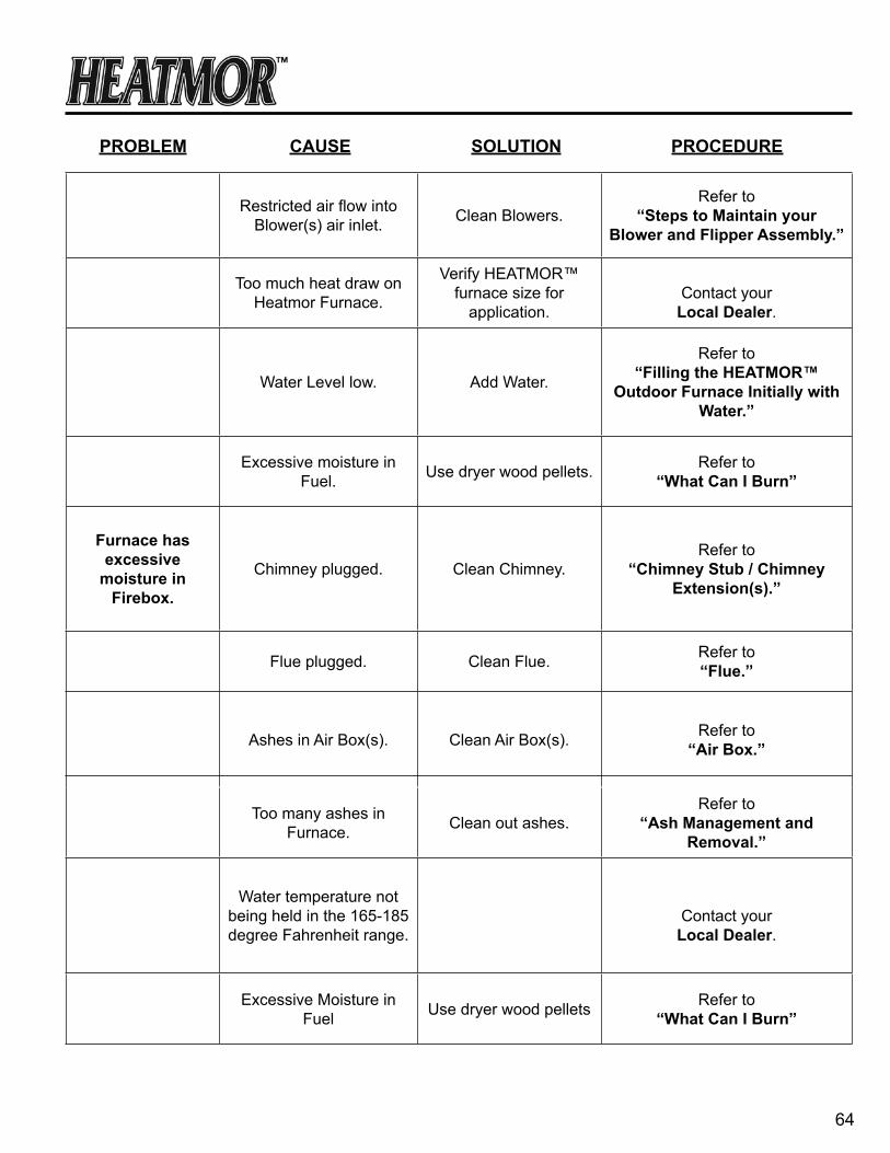
64
Restricted air flow into Blower(s) air inlet. Clean Blowers.
Refer to “steps to Maintain your
Blower and Flipper assembly.”
Too much heat draw on Heatmor Furnace.
Verify HEATMOR™ furnace size for
application.Contact your
Local Dealer.
Water Level low. Add Water.
Refer to“Filling the heatMOr™
Outdoor Furnace initially with Water.”
Excessive moisture in Fuel. Use dryer wood pellets. Refer to
“What can i Burn”
Furnace has excessive
moisture in Firebox.
Chimney plugged. Clean Chimney.Refer to
“chimney stub / chimney extension(s).”
Flue plugged. Clean Flue. Refer to “Flue.”
Ashes in Air Box(s). Clean Air Box(s). Refer to “air Box.”
Too many ashes in Furnace. Clean out ashes.
Refer to “ash Management and
removal.”
Water temperature not being held in the 165-185 degree Fahrenheit range.
Contact yourLocal Dealer.
Excessive Moisture in Fuel Use dryer wood pellets Refer to
“What can i Burn”
PrOBLeM cause sOLutiOn PrOceDure
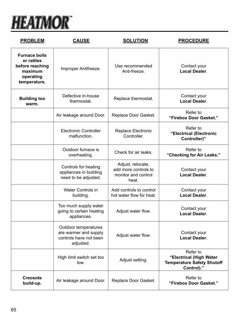
65
Furnace boils
or rattles before reaching
maximum operating
temperature.
Improper Antifreeze. Use recommended Anti-freeze.
Contact yourLocal Dealer.
Building too warm.
Defective in-house thermostat. Replace thermostat. Contact your
Local Dealer.
Air leakage around Door. Replace Door Gasket. Refer to “Firebox Door gasket.”
Electronic Controller malfunction.
Replace Electronic Controller.
Refer to “electrical (electronic
controller)”
Outdoor furnace is overheating. Check for air leaks. Refer to
“checking for air Leaks.”
Controls for heating appliances in building need to be adjusted.
Adjust, relocate, add more controls to monitor and control
heat.
Contact yourLocal Dealer.
Water Controls in building.
Add controls to control hot water flow for heat.
Contact yourLocal Dealer.
Too much supply water going to certain heating
appliances.Adjust water flow. Contact your
Local Dealer.
Outdoor temperatures are warmer and supply controls have not been
adjusted.
Adjust water flow. Contact yourLocal Dealer.
High limit switch set too low. Adjust setting.
Refer to “electrical (high Water
temperature safety shutoff control).”
creosote build-up. Air leakage around Door. Replace Door Gasket. Refer to
“Firebox Door gasket.”
PrOBLeM cause sOLutiOn PrOceDure

66
Firebox receiving air somewhere when
fans are off.
Check all seals for air leaks.
Run a smoke check.
Refer to “checking for air Leaks.”
Fire is not burning hot.
Check type of wood pellets burning and if blower is working
properly.
Refer to “What can i burn,
combustion air Blower / Flipper assembly”
Burning wood pellets that are too wet.
Add wood pellets with the correct moisture
content.
Refer to “What can i Burn”
Air flow is not sufficient for the type of fuel.
Check and clean fan blades. Check and
clean flipper assembly.
Refer to “combustion air Blower /
Flipper assembly”
Ashes in Air Box(s). Clean Air Box(s). Refer to “air Box.”
Chimney Plugged. Clean Chimney. Refer to “chimney”
Flue plugged. Clean Flue. Refer to “Flue.”
Water temperature not being held in the 165 to
185 degree rangeConsult Dealer. Contact your
Local Dealer.
thermometer(temp gauge)
exceeds 212 degrees Fahrenheit.
Furnace is not boiling.
Low water level Add water.(Let Furnace cool first)
Refer to “Water Level Maintenance.”
charcoal build-up in firepot. Excessive ashes. Remove ashes.
Refer to “ash Management and ash
removal.”
Burning wood pellets with a high ash content
Burn wood pellets with low ash content
Refer to “What can i Burn”
PrOBLeM cause sOLutiOn PrOceDure
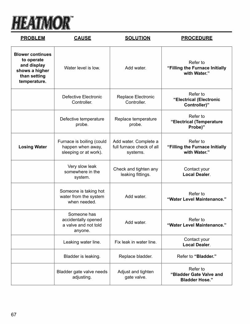
67
Blower continues to operate
and display shows a higher
than setting temperature.
Water level is low. Add water.Refer to
“Filling the Furnace initially with Water.”
Defective Electronic Controller.
Replace Electronic Controller.
Refer to “electrical (electronic
controller)”
Defective temperature probe.
Replace temperature probe.
Refer to “electrical (temperature
Probe)”
Losing WaterFurnace is boiling (could
happen when away, sleeping or at work).
Add water. Complete a full furnace check of all
systems.
Refer to“Filling the Furnace initially
with Water.”
Very slow leak somewhere in the
system.
Check and tighten any leaking fittings.
Contact yourLocal Dealer.
Someone is taking hot water from the system
when needed.Add water. Refer to
“Water Level Maintenance.”
Someone has accidentally opened a valve and not told
anyone.
Add water. Refer to “Water Level Maintenance.”
Leaking water line. Fix leak in water line. Contact yourLocal Dealer.
Bladder is leaking. Replace bladder. Refer to “Bladder.”
Bladder gate valve needs adjusting.
Adjust and tighten gate valve.
Refer to “Bladder gate valve and
Bladder hose.”
PrOBLeM cause sOLutiOn PrOceDure
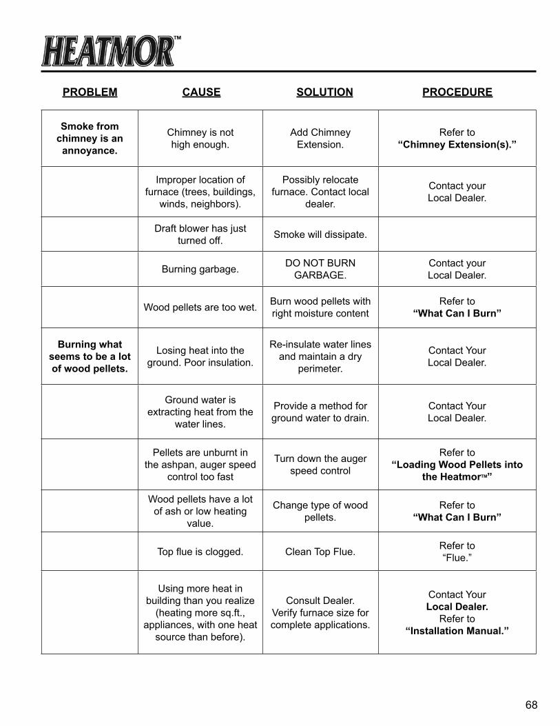
68
smoke from chimney is an annoyance.
Chimney is not high enough.
Add Chimney Extension.
Refer to “chimney extension(s).”
Improper location of furnace (trees, buildings,
winds, neighbors).
Possibly relocate furnace. Contact local
dealer.
Contact yourLocal Dealer.
Draft blower has just turned off. Smoke will dissipate.
Burning garbage. DO NOT BURN GARBAGE.
Contact yourLocal Dealer.
Wood pellets are too wet. Burn wood pellets with right moisture content
Refer to “What can i Burn”
Burning what seems to be a lot of wood pellets.
Losing heat into the ground. Poor insulation.
Re-insulate water lines and maintain a dry
perimeter.
Contact YourLocal Dealer.
Ground water is extracting heat from the
water lines.
Provide a method for ground water to drain.
Contact YourLocal Dealer.
Pellets are unburnt in the ashpan, auger speed
control too fast
Turn down the auger speed control
Refer to “Loading Wood Pellets into
the heatmortM”
Wood pellets have a lot of ash or low heating
value.
Change type of wood pellets.
Refer to “What can i Burn”
Top flue is clogged. Clean Top Flue. Refer to “Flue.”
Using more heat in building than you realize
(heating more sq.ft., appliances, with one heat
source than before).
Consult Dealer.Verify furnace size for complete applications.
Contact YourLocal Dealer.
Refer to“installation Manual.”
PrOBLeM cause sOLutiOn PrOceDure

69
cannot get building(s) warm
enough.
Insufficient heating devices in building. Consult Dealer. Contact Your
Local Dealer.
Improperly installed heating devices
in building.
Correct installation of heating devices.
Contact YourLocal Dealer.
Heating devices need maintenance.
Maintain heating devices.
Contact YourLocal Dealer.
HEATMOR™ not running between 145-185
degrees Fahrenheit.Consult Dealer. Contact Your
Local Dealer.
Insufficient water circulation from HEATMOR™.
a) Check circulating pumps. Replace if
necessary .b) Line that is kinked.
c) Air in system.d) Need a larger pump.e) Lines are too small.
f) Pump has a restriction in the intake (piece of plastic or foil).
Contact YourLocal Dealer.
Refer to“installation Manual.”
Unbalanced supply water distribution.
Re-balance and distribute water from
outdoor furnace.Balance the system by adjusting the flows of water to the different heating appliances.
Contact yourLocal Dealer.
Refer toInstallation Manual.
One appliance getting more than it’s share of
the total flow of hot water.
Balance the system by adjusting the flows of water to the different heating appliances.
Contact yourLocal Dealer.
Defective in house (building) thermostat and
controls.
Replace thermostats and controls.
Contact yourLocal Dealer.
PrOBLeM cause sOLutiOn PrOceDure

70
Faulty electrical supply. Check electrical connections.
Contact yourelectrician.
Indoor forced air furnace fan is full of dirt or filter
is plugged and therefore the air flow is reduced going through the coil.
Contact yourLocal Dealer.
Improper installation of coil in forced air furnace.
Contact yourLocal Dealer.
Too small a coil in forced air furnace.
Auger Speed too low Increase Auger Speed refer to “Dayton auger speed control”
Inadequate Baseboard.
When a water-to-water heat exchanger is
installed, a temp drop of 20-30° across heat
exchanger may be experienced.
Contact yourLocal Dealer.
not enough domestic hot
water.
Hot water heater is too small.
Sidearm exchanger needs to have a pump
installed.
Refer to“installation Manual.”
Somewhere in the domestic water system
of the house, the hot and the cold can mix, (as in a single faucet outlet) and the resulting mixed warm water is being sent to the hotwater taps instead of
pure hotwater
Contact your Local Dealer.
PrOBLeM cause sOLutiOn PrOceDure
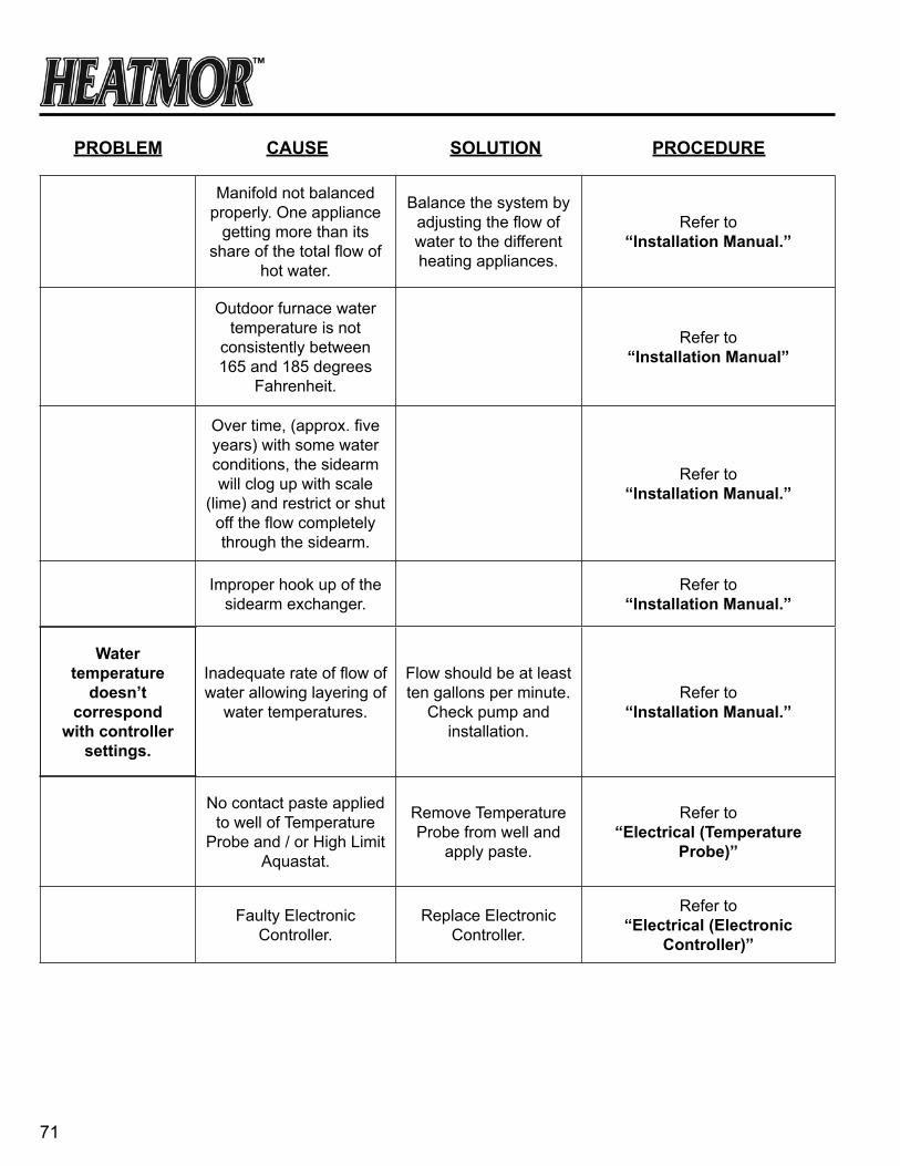
71
Manifold not balanced properly. One appliance
getting more than its share of the total flow of
hot water.
Balance the system by adjusting the flow of water to the different heating appliances.
Refer to“installation Manual.”
Outdoor furnace water temperature is not
consistently between 165 and 185 degrees
Fahrenheit.
Refer to“installation Manual”
Over time, (approx. five years) with some water conditions, the sidearm will clog up with scale
(lime) and restrict or shut off the flow completely through the sidearm.
Refer to“installation Manual.”
Improper hook up of the sidearm exchanger.
Refer to“installation Manual.”
Water temperature
doesn’t correspond
with controller settings.
Inadequate rate of flow of water allowing layering of
water temperatures.
Flow should be at least ten gallons per minute.
Check pump and installation.
Refer to“installation Manual.”
No contact paste applied
to well of Temperature Probe and / or High Limit
Aquastat.
Remove Temperature Probe from well and
apply paste.
Refer to “electrical (temperature
Probe)”
Faulty Electronic Controller.
Replace Electronic Controller.
Refer to “electrical (electronic
controller)”
PrOBLeM cause sOLutiOn PrOceDure
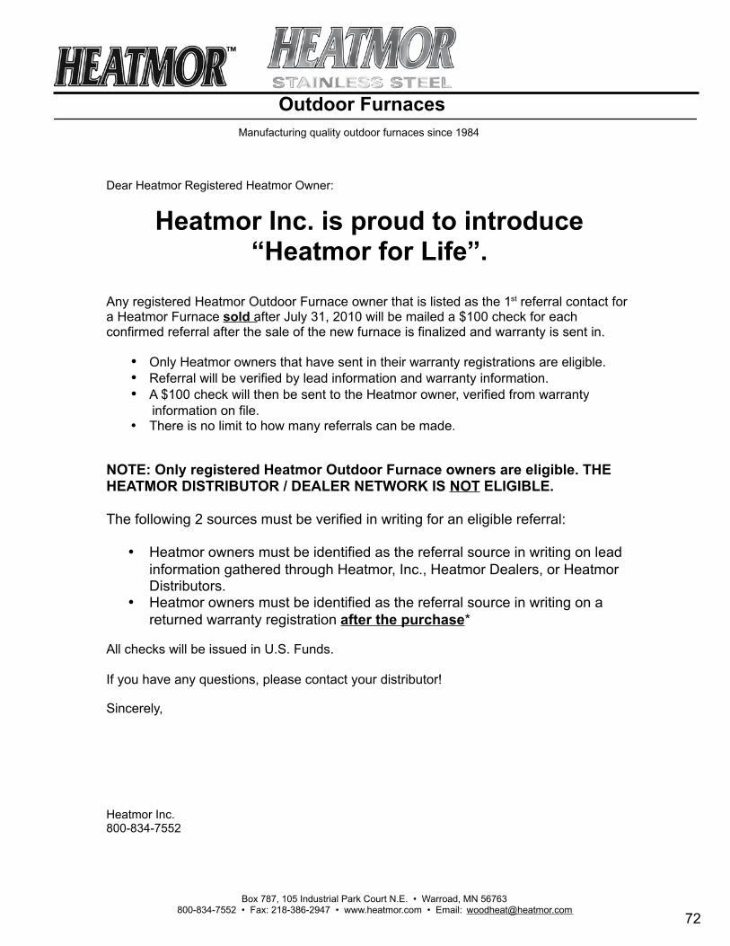
72
Outdoor Furnaces
•••
•
•
•*

73
PLease reaD the heatMOrtM stainLess steeL LiMiteD LiFetiMe Warranty.
iF yOu have any QuestiOns, PLease cOntact yOur LOcaL DeaLer.
cOMPLete anD senD the Furnace registratiOn tO yOur LOcaL DeaLer, DistriButOr Or heatMOr inc. Within
30 Days OF Purchase Date tO vaLiDate the Warranty.
74

NE
W F
UR
NA
CE
D
ELI
VE
RY
CH
EC
K S
HE
ET
___
____
____
____
____
____
____
____
____
____
____
____
____
___
____
____
____
____
____
____
___
____
____
____
____
____
____
___
___
____
____
____
____
____
____
___
_
____
____
____
____
____
____
____
_
___
____
____
____
____
____
____
___
_
____
____
____
____
____
____
____
_
D
EA
LER
D
EA
LER
SH
IP N
AM
E
(
Ple
ase
prin
t)
(P
leas
e pr
int)
DE
LIV
ER
Y C
HE
CK
LIS
T C
US
TOM
ER
AP
PR
OV
AL
I hav
e in
spec
ted
my
new
Hea
tmor
and
ac
know
ledg
e th
at a
ll th
e ite
ms
on th
e de
liver
y ch
eckl
ist h
ave
been
revi
ewed
with
m
e by
the
sale
sper
son.
I ha
ve b
een
pres
ente
d w
ith a
key
for m
y lo
cked
H
eatm
or a
nd a
ssum
e th
e re
spon
sibi
lity
of
oper
atio
n an
d m
aint
enan
ce o
f it.
____
____
____
____
____
____
____
____
____
____
____
____
Cus
tom
er S
igna
ture
__
____
____
____
____
____
____
____
____
____
____
__
Dat
e
Rev
iew
ow
ners
man
ual.
Des
crib
e in
stal
latio
ns m
etho
ds a
nd
reco
mm
enda
tions
.
Rev
iew
war
rant
y an
d m
aint
enan
ce r
equi
rem
ents
.
Exp
lain
req
uire
d m
aint
enan
ce s
ched
ule.
Dem
onst
rate
saf
ety
haza
rds
and
prop
er o
pera
tion
of H
eatm
or.
Des
crib
e po
ssib
le p
robl
ems
caus
ed b
y di
ffere
nt
woo
d/co
nditi
ons.
Mod
el:
100C
SS
2
00C
SS
4
00D
CS
S
600
CS
S
800
CS
S
S
eria
l No.
___
____
____
____
__ D
ate:
____
____
____
Cop
y D
istri
butio
n W
hite
– H
eatm
or
Pin
k –
Dea
ler
Yel
low
– D
istri
buto
r
Gol
d - C
usto
mer
(Ple
ase
prin
t)
NE
W F
UR
NA
CE
D
EL
IVE
RY
CH
EC
K S
HE
ET
_
____
____
____
____
____
____
____
____
____
____
____
____
____
___
____
____
____
____
____
____
___
____
____
____
____
____
____
_
_
____
____
____
____
____
____
____
_
___
____
____
____
____
____
____
___
_
____
____
____
____
____
____
____
_
___
____
____
____
____
____
____
___
D
EA
LER
D
EA
LE
RS
HIP
NA
ME
(
Ple
ase
pri
nt)
(
Ple
ase
print)
DE
LIV
ER
Y C
HE
CK
LIS
T
CU
ST
OM
ER
AP
PR
OV
AL
I have
insp
ect
ed m
y ne
w H
eatm
or
and
ack
now
ledge t
hat all
the it
em
s on t
he
deliv
ery
check
list have
been r
evi
ew
ed w
ith
me b
y th
e s
ale
spers
on. I
have
been
pre
sente
d w
ith a
key
for
my
lock
ed
Heatm
or
and a
ssum
e t
he r
esp
onsi
bili
ty o
f opera
tion a
nd m
ain
tenance
of it.
__
____
____
____
____
____
____
____
____
____
____
____
__
Cust
omer
Sig
natu
re
__
____
____
____
____
____
____
____
____
____
____
__
Date
Revi
ew
ow
ners
manual.
Desc
ribe in
stalla
tions
meth
ods
and
reco
mm
endatio
ns.
Revi
ew
warr
anty
and m
ain
tenance
req
uirem
ents
.
Exp
lain
req
uired m
ain
tenance
sch
edule
.
Dem
onst
rate
safe
ty h
aza
rds
and p
roper
opera
tion
of
Heatm
or.
Desc
ribe p
oss
ible
pro
ble
ms
cause
d b
y diff
ere
nt
wood/c
onditi
ons.
Mode
l: 1
00C
SS
2
00C
SS
4
00D
CS
S 6
00C
SS
8
00C
SS
S
erial N
o.
____
____
____
____
_ D
at e
:___
____
____
_
Copy
Dis
trib
utio
n
Whi
te –
Heat
mor
P
ink
– D
eale
r Y
ello
w –
Dis
trib
uto
r
Gold
- C
ust
omer
(Ple
ase
pri
nt)
NE
W F
UR
NA
CE
D
ELI
VE
RY
CH
EC
K S
HE
ET
___
____
____
____
____
____
____
____
____
____
____
____
____
___
____
____
____
____
____
____
___
____
____
____
____
____
____
___
___
____
____
____
____
____
____
___
_
____
____
____
____
____
____
____
_
___
____
____
____
____
____
____
___
_
____
____
____
____
____
____
____
_
D
EA
LER
D
EA
LER
SH
IP N
AM
E
(
Ple
ase
prin
t)
(P
leas
e pr
int)
DE
LIV
ER
Y C
HE
CK
LIS
T C
US
TOM
ER
AP
PR
OV
AL
I hav
e in
spec
ted
my
new
Hea
tmor
and
ac
know
ledg
e th
at a
ll th
e ite
ms
on th
e de
liver
y ch
eckl
ist h
ave
been
revi
ewed
with
m
e by
the
sale
sper
son.
I ha
ve b
een
pres
ente
d w
ith a
key
for m
y lo
cked
H
eatm
or a
nd a
ssum
e th
e re
spon
sibi
lity
of
oper
atio
n an
d m
aint
enan
ce o
f it.
____
____
____
____
____
____
____
____
____
____
____
____
Cus
tom
er S
igna
ture
__
____
____
____
____
____
____
____
____
____
____
__
Dat
e
Rev
iew
ow
ners
man
ual.
Des
crib
e in
stal
latio
ns m
etho
ds a
nd
reco
mm
enda
tions
.
Rev
iew
war
rant
y an
d m
aint
enan
ce r
equi
rem
ents
.
Exp
lain
req
uire
d m
aint
enan
ce s
ched
ule.
Dem
onst
rate
saf
ety
haza
rds
and
prop
er o
pera
tion
of H
eatm
or.
Des
crib
e po
ssib
le p
robl
ems
caus
ed b
y di
ffere
nt
woo
d/co
nditi
ons.
Mod
el:
100C
SS
2
00C
SS
4
00D
CS
S
600
CS
S
800
CS
S
S
eria
l No.
___
____
____
____
__ D
ate:
____
____
____
Cop
y D
istri
butio
n W
hite
– H
eatm
or
Pin
k –
Dea
ler
Yel
low
– D
istri
buto
r
Gol
d - C
usto
mer
(Ple
ase
prin
t)
NE
W F
UR
NA
CE
D
ELI
VE
RY
CH
EC
K S
HE
ET
___
____
____
____
____
____
____
____
____
____
____
____
____
___
____
____
____
____
____
____
___
____
____
____
____
____
____
___
___
____
____
____
____
____
____
___
_
____
____
____
____
____
____
____
_
___
____
____
____
____
____
____
___
_
____
____
____
____
____
____
____
_
D
EA
LER
D
EA
LER
SH
IP N
AM
E
(
Ple
ase
prin
t)
(P
leas
e pr
int)
DE
LIV
ER
Y C
HE
CK
LIS
T C
US
TOM
ER
AP
PR
OV
AL
I hav
e in
spec
ted
my
new
Hea
tmor
and
ac
know
ledg
e th
at a
ll th
e ite
ms
on th
e de
liver
y ch
eckl
ist h
ave
been
revi
ewed
with
m
e by
the
sale
sper
son.
I ha
ve b
een
pres
ente
d w
ith a
key
for m
y lo
cked
H
eatm
or a
nd a
ssum
e th
e re
spon
sibi
lity
of
oper
atio
n an
d m
aint
enan
ce o
f it.
____
____
____
____
____
____
____
____
____
____
____
____
Cus
tom
er S
igna
ture
__
____
____
____
____
____
____
____
____
____
____
__
Dat
e
Rev
iew
ow
ners
man
ual.
Des
crib
e in
stal
latio
ns m
etho
ds a
nd
reco
mm
enda
tions
.
Rev
iew
war
rant
y an
d m
aint
enan
ce r
equi
rem
ents
.
Exp
lain
req
uire
d m
aint
enan
ce s
ched
ule.
Dem
onst
rate
saf
ety
haza
rds
and
prop
er o
pera
tion
of H
eatm
or.
Des
crib
e po
ssib
le p
robl
ems
caus
ed b
y di
ffere
nt
woo
d/co
nditi
ons.
Mod
el:
100C
SS
2
00C
SS
4
00D
CS
S
600
CS
S
800
CS
S
S
eria
l No.
___
____
____
____
__ D
ate:
____
____
____
Cop
y D
istri
butio
n W
hite
– H
eatm
or
Pin
k –
Dea
ler
Yel
low
– D
istri
buto
r
Gol
d - C
usto
mer
(Ple
ase
prin
t)
Cop
y D
istri
butio
nYe
llow
- H
eatm
orG
reen
- D
istri
buto
rP
ink
- Dea
ler
Gol
d - C
usto
mer
200S
SR
40
0SS
R
200S
SR
II
NE
W F
UR
NA
CE
D
ELI
VE
RY
CH
EC
K S
HE
ET
___
____
____
____
____
____
____
____
____
____
____
____
____
___
____
____
____
____
____
____
___
____
____
____
____
____
____
___
___
____
____
____
____
____
____
___
_
____
____
____
____
____
____
____
_
___
____
____
____
____
____
____
___
_
____
____
____
____
____
____
____
_
D
EA
LER
D
EA
LER
SH
IP N
AM
E
(
Ple
ase
prin
t)
(P
leas
e pr
int)
DE
LIV
ER
Y C
HE
CK
LIS
T C
US
TOM
ER
AP
PR
OV
AL
I hav
e in
spec
ted
my
new
Hea
tmor
and
ac
know
ledg
e th
at a
ll th
e ite
ms
on th
e de
liver
y ch
eckl
ist h
ave
been
revi
ewed
with
m
e by
the
sale
sper
son.
I ha
ve b
een
pres
ente
d w
ith a
key
for m
y lo
cked
H
eatm
or a
nd a
ssum
e th
e re
spon
sibi
lity
of
oper
atio
n an
d m
aint
enan
ce o
f it.
____
____
____
____
____
____
____
____
____
____
____
____
Cus
tom
er S
igna
ture
__
____
____
____
____
____
____
____
____
____
____
__
Dat
e
Rev
iew
ow
ners
man
ual.
Des
crib
e in
stal
latio
ns m
etho
ds a
nd
reco
mm
enda
tions
.
Rev
iew
war
rant
y an
d m
aint
enan
ce r
equi
rem
ents
.
Exp
lain
req
uire
d m
aint
enan
ce s
ched
ule.
Dem
onst
rate
saf
ety
haza
rds
and
prop
er o
pera
tion
of H
eatm
or.
Des
crib
e po
ssib
le p
robl
ems
caus
ed b
y di
ffere
nt
woo
d/co
nditi
ons.
Mod
el:
100C
SS
2
00C
SS
4
00D
CS
S
600
CS
S
800
CS
S
S
eria
l No.
___
____
____
____
__ D
ate:
____
____
____
Cop
y D
istri
butio
n W
hite
– H
eatm
or
Pin
k –
Dea
ler
Yel
low
– D
istri
buto
r
Gol
d - C
usto
mer
(Ple
ase
prin
t)
200S
SR
II