
OUTDOOR COMBINATION OIL-FIRED FURNACE … COMBINATION OIL-FIRED FURNACE AND AIR CONDITIONING UNIT...
91
OUTDOOR COMBINATION OIL-FIRED FURNACE AND AIR CONDITIONING UNIT MODEL OPA INSTALLATION AND SERVICE MANUAL Please read these instructions prior to installation, initial firing, and before performing any service or maintenance. These instructions must be retained by the homeowner for future reference by qualified heating contractor. Thermo Products, LLC PO Box 217 MO-424 North Judson, IN 46366 ECN 4650-MA Phone: (574) 896-2133 Made In USA : If the information in this manual is not followed exactly, a fire or explosion may result causing property damage, personal injury, or loss of life. − Do not store or use gasoline or other flammable vapors and liquids in the vicinity of this or any other appliance. − WHAT TO DO IF YOU FIND AN OIL LEAK: • Do not try to light any appliance. • Immediately call your oil supplier. • If you cannot reach your oil supplier, call the fire department. − Installation and service must be performed by a qualified installer, service agency or the oil supplier. (These entities are referred to in these instructions as a qualified heating contractor).
Transcript of OUTDOOR COMBINATION OIL-FIRED FURNACE … COMBINATION OIL-FIRED FURNACE AND AIR CONDITIONING UNIT...

OUTDOOR COMBINATION OIL-FIRED FURNACE AND AIR CONDITIONING UNIT
MODEL OPA
INSTALLATION AND SERVICE MANUAL Please read these instructions prior to installation, initial firing, and before performing any service or maintenance. These instructions must be retained by the homeowner for future reference by qualified heating contractor.
Thermo Products, LLC PO Box 217
MO-424 North Judson, IN 46366 ECN 4650-MA Phone: (574) 896-2133 Made In USA
: If the information in this manual is not followed exactly, a
fire or explosion may result causing property damage, personal injury, or loss of life.
− Do not store or use gasoline or other flammable vapors and liquids in the
vicinity of this or any other appliance. − WHAT TO DO IF YOU FIND AN OIL LEAK:
• Do not try to light any appliance. • Immediately call your oil supplier. • If you cannot reach your oil supplier, call the fire department.
− Installation and service must be performed by a qualified installer, serviceagency or the oil supplier. (These entities are referred to in these instructionsas a qualified heating contractor).

All installations and services must be performed by qualified service personnel.
1
Contents SECTION PAGE I. SAFETY INFORMATION .............................…………………………………….3 II. GENERAL INSTRUCTIONS ...........................................………………….…..9 III. GENERAL INSTALLATION .....................................................………………. 9
A. Codes and Clearances .......................................................……………. 10 B. Selection of Installation Location .........................................…………… 11 C. Venting Of Combustion Products ............................................………….13 D. Condensate Drain ....................................................................…………14 E. Oil Tank and Piping ..................................................................... ……... 15 F. Oil Filter .......................................................................................……… 17 G. Burner Specifications and Performance .......................................…….. 17 H. Airflow Requirements and Sizing of Ductwork ..............................…….. 19 I. Air Filters ......................................................................................…….. 23
1. Filter Installation ......................................................................…….. 23 2. Use of non-Thermo Pride Filters or Retention Means ..............……. 23
J. Electrical Wiring .............................................................................……. 24 1. Electronic Air Cleaner (EAC) and Humidifier Installation ..........…… 26 2. Thermostat Anticipator Setting.................................................…….. 28 3. Blower Motor Speed Selection .................................................……. 30
IV. STARTUP PROCEDURES.........................................................................…….32 A. HEATING SYSTEM
1. Initial Startup .............................................................................…….32 2. Adjustment of Burner Combustion .............................................…… 34 3. Adjustment of Heat Input Rate ...................................................…… 37 4. Setting Supply Air Temperature Rise .....................................……... 38 5. Checkout Procedure ................................................................…….. 39
B. COOLING SYSTEM 1. Initial Startup ......................................................................….……... 41 2. Definition of Superheat .......................................................... ……... 42 3. Evaporator Superheat ...........................................................………. 43 4. Definition of Subcooling ..........................................................…….. 44 5. Condenser Subcooling ...........................................................…….. 44 6. Recommendations for Operation at Low Temperatures ............… 45
V. INSTALLER'S INSTRUCTIONS TO USER ..........................................….. 46

All installations and services must be performed by qualified service personnel.
2
Contents SECTION PAGE VI. DEALER MAINTENANCE ................................................................ ……... 47 A. General Inspection ...................................................................... ……... 47 B. Heat Exchanger ........................................................................………. 48
1. Disassembly to Access Heat Exchanger ...............................……… 48 2. Reassembly of Unit ................................................................……… 50 3. Operational Check ..................................................................…….. 51
C. Electrical System ...........................................................................……. 51 D. Supply/Return Air Blower .............................................................……... 52 E. Supply/Return Air Filter ................................................................…….. 52
1. Filter Maintenance ...................................................................…….. 52 2. Filter Replacement ...................................................................……. 52
F. Extended Appliance Shutdown ....................................................……... 53
VII. HOMEOWNER/USER INFORMATION AND ROUTINE MAINTENANCE ..55 VIII. TROUBLESHOOTING .........................................................................…… 59
A. Heating System ................................................................................….. 59 B. Cooling System .................................................................................…. 60
IX. REFERENCES .......................................................................................…. 62 X. APPENDIX A: SOURCES FOR REFERENCED STANDARDS .............…. 63 XI. APPENDIX B: CALCULATIONS ...........................................................….. 64 XII. APPENDIX C: ELECTRICAL SCHEMATIC AND CONNECTION DIAGRAM
.................................................................................................................…. 75 XIII. APPENDIX D: SEQUENCE OF OPERATIONS ....................................….. 76 XIV. APPENDIX E: TROUBLESHOOTING FLOWCHARTS .........................….. 78 XV. APPENDIX F: SPECIFICATION SHEETS .............................................…. 86 XVI. APPENDIX G: REPLACEMENT PARTS ...............................................….. 87 XVII. APPENDIX H: OPA HEATING AND COOLING TEST FORM ...............…. 89 WARRANTY …………………………………………………………………….. 90

All installations and services must be performed by qualified service personnel.
3
I. SAFETY INFORMATION This page and the following page contain reproductions of the various instructions and warning labels placed on the Thermo Pride gas-fired appliances. Please read and comply with the contents of these labels.

All installations and services must be performed by qualified service personnel.
4

All installations and services must be performed by qualified service personnel.
5
The following warnings and cautions are found throughout the Thermo Pride Model OPA Installation and Service Manual. Please read and comply with the statements below.
: IF YOU DO NOT FOLLOW THESE INSTRUCTIONS EXACTLY, A FIRE OR EXPLOSION MAY RESULT CAUSING PROPERTY DAMAGE, PERSONAL INJURY, OR LOSS OF LIFE.
: Carefully read and thoroughly understand the following guidelines and
warnings before continuing with the installation of this unit. Failure to follow these guidelines can cause improper and unsafe operation of this appliance. Unsafe operation can result in substantial property damage, severe personal injury, or death.
: This unit is not to be used for temporary heating of buildings, or structures, under construction.
: Maximum gross stack temperature must not exceed 550°F (288°C) under any circumstances.
: Failure to comply with minimum filter installation requirements may effect the performance and/or void the warranty on this unit.
: This appliance must be grounded in accordance with local codes or in the absence of local codes with the National Electrical Code, ANSI/NFPA 70 –1999, or the latest edition.
: Turn off the electrical power to the appliance before attempting to change supply air blower speed wiring.
: Personal injury or property damage could result from repair, or service, of this appliance by anyone other than a qualified heating contractor. The end user may only perform the service described under the Homeowner/User Routine Maintenance section of this manual.
: To avoid injury from moving parts or electrical shock, shut off the power to the appliance before removing supply air blower compartment door and servicing this appliance.
: When servicing controls, label all wires prior to disconnecting. Reconnect any wires removed correctly. Wiring errors can cause improper and dangerous operation. Dangerous operation can result in injury or damage.
: Disconnect electrical power before servicing this unit.
All installations and services must be performed by qualified service personnel.
6
: Waterproof type connectors must be used when connecting electrical power and control wiring to the unit to prevent moisture from being drawn into the unit during operation. : Refrigerant is under pressure. Guard against refrigerant spraying into the face or on skin. Always wear protective equipment, i.e. safety glasses or goggles and gloves when working with refrigerant.
: Do not under any circumstances heat the refrigerant cylinder with a torch or
by any other means other than warm water. Excessive pressures generated in this manner may weaken the refrigerant container and result in an explosion!
: To avoid injury from moving parts, or electrical shock, shut off the power to the appliance before removing blower compartment door and servicing this appliance.
: When servicing controls, label all wires prior to disconnecting. Reconnect any
removed wires correctly. Wiring errors can cause improper and dangerous operation. Dangerous operation can result in injury or damage.
: Do not use this appliance if any part has been under water. Immediately call a qualified service technician to inspect the furnace and to replace any part of the control system and any gas control that has been under water.
: The area around the appliance, including the top of the unit, must be kept clear and free of combustible materials, gasoline, and other flammable vapors and liquids.
: The appliance vent terminal may be hot. If the terminal is hot, allow it to cool
before touching it.
: Shut off unit and disconnect the power source before disassembling the unit.
: Never operate the appliance without clean air filters in place.
: This appliance requires air for combustion, ventilation, and cooling. Do not block or obstruct air openings in the unit and the air space around the perimeter of the unit.
: All local codes and ordinances take precedence with regard to selection and installation of oil storage tank and oil supply (and return) lines. In the absence of local codes, all tanks and lines must be selected and installed according to the instructions in this manual and the Standard for the Installation of Oil-Burning Equipment, NFPA 31-1997, or the latest edition.
: Turn off power to furnace. Before the oil piping system is placed into service, it must have been leak tested by a qualified heating contractor.

All installations and services must be performed by qualified service personnel.
7
: For initial start-up of the appliance after installation, it may be necessary to
purge the air out of the oil line. A qualified heating contractor should do this.
: If you do not follow these instructions exactly, a fire or explosion may result causing property damage, personal injury or loss of life. : Do not run the oil pump dry for more than five minutes, as irreparable damage may result.
: Before troubleshooting, familiarize yourself with the start up and check out procedures.
: Never burn garbage or refuse in this appliance. Never try to ignite oil by tossing burning papers or other material into the combustion chamber.
: Oil-fired appliances produced by Thermo Products are designed for burning No. 2 distillate (domestic heating) fuel oil. Never use gasoline or a mixture of oil and gasoline. I : Do not attempt to make repairs yourself. Contact your local qualified heating contractor.
: This appliance is designed to directly vent combustion products into the atmosphere through, and using only, the supplied vent terminal. Do not attempt to attach a vent connector or a vent system to, or in place of, the supplied vent terminal.
: Do not attempt to operate the cooling section on a day when outdoor temperatures are 45°F or cooler.

All installations and services must be performed by qualified service personnel.
8
: Carefully read and thoroughly understand the following guidelines and warnings before continuing with the installation of this appliance. Failure to follow these guidelines can cause improper and unsafe operation of this appliance. Unsafe operation can result in substantial property damage, severe personal injury, or death. 1. This appliance shall be used with only the type of fuel oil for which it is approved.
Refer to the appliance-rating label for the required type of fuel. 2. This appliance is a single, packaged, oil-fired furnace with air conditioner designed
for outdoor installation on either combustible or non-combustible materials. This appliance is also approved for rooftop installation on combustible or non-combustible roofing materials.
3. Ensure that adequate combustion and ventilation air is available to the unit. 4. The airflow resistance of the duct system attached to this appliance must fall within
the allowable external static pressure range for this unit. Refer to the Airflow Requirements and Sizing of Ductwork section of this manual.
5. Make sure supply and return air ducts are completely sealed to the appliance
casing. Refer to the Airflow Requirements and Sizing of Ductwork section of this manual.

All installations and services must be performed by qualified service personnel.
9
II. GENERAL INSTRUCTIONS The entire text of these instructions must be read and understood, before installing the appliance. It is the installer's responsibility to do the following:
1. Inform and demonstrate to the user, the correct operation and maintenance of
the appliance, as explained in the Homeowner/User Information and Routine Maintenance section of this manual.
2. Inform the user of the hazards of flammable liquids and vapors and to remove such liquids and vapors from the vicinity of the appliance.
3. Inform the user of all pertinent warnings and precautions concerning this appliance.
III. GENERAL INSTALLATION
: This unit is not to be used for temporary heating of buildings, or
structures, under construction. Construction dust may enter the appliance or the duct system and cause a fire hazard. Certain chemicals used during construction when burned, form corrosive condensate that can substantially reduce the life of the heating system heat exchanger. With exception of the vent terminal, this appliance is shipped completely assembled and internally wired. All fuel oil and refrigerant piping, refrigerant charge, and electrical wiring have been factory installed and inspected. At the time of installation, the unit will require connection to electric power, fuel oil supply, condensate drain, and supply and return air ductwork. In addition, the vent termination kit will need assembly. In the event of a shortage of parts or damage, refer to the Dealer Receiving and Freight Claim Procedure section of the Price Guide.
This unit uses a fan-assisted combustion system, consisting of a pressure atomizing, oil burner and combustion air blower, used to push the products of combustion through the heat exchanger system. After installation, the furnace and duct system must be adjusted to obtain a temperature rise of 50°F to 80°F through the unit. (Refer to the rating label located on side panel inside the burner compartment). The installation must conform with local codes or, in the absence of local codes, with the Standard for the Installation of Oil-Burning Equipment, NFPA 31-1997, or the latest edition, and to these instructions.

All installations and services must be performed by qualified service personnel.
10
A. Codes and Clearances: The following items must be considered when choosing the size and location of the unit. 1. All local codes and/or regulations take precedence over the instructions
in this manual and should be followed accordingly. In the absence of local codes, installation must conform to these instructions and the guidelines of the National Fire Protection Association (NFPA). Two applicable NFPA installation codes are the National Electrical Code, ANSI/NFPA 70-1999, and Standard for the Installation of Oil-Burning Equipment, NFPA 31-1997. The latest editions of these codes should be consulted.
2. The selection of a heating unit should be based on a rate of heat loss
calculation for the residence according to the manuals provided by the Air Conditioning Contractors of America (ACCA) or the American Society of Heating, Refrigeration, and Air Conditioning Engineers (ASHRAE). The heating capacity of the unit proposed for installation should meet or slightly exceed the rate of heat loss for the residence. Oversizing should not exceed 125% of the heat loss calculation.
3. When installed, this unit should be level. If possible, it should be installed in a central location, with respect to outlet registers of the supply air ductwork.
4. Definitions of "combustible" and "non-combustible" materials as presented in the 1996 version of the National Fuel Gas Code, ANSI Z223.1-1996/NFPA 70-1996, are as follows:
a. Combustible material: “...materials made of or surfaced with wood, compressed paper, plant fibers, or other materials that are capable of being ignited and burned. Such materials shall be considered combustible even though flameproofed, fire-retardant treated, or plastered.”
b. Non-combustible material:
“...material that is not capable of being ignited and burned; such as material consisting entirely of, or a combination of, steel, iron, brick, concrete, slate, asbestos, glass, and plaster.”
All installations and services must be performed by qualified service personnel.
11
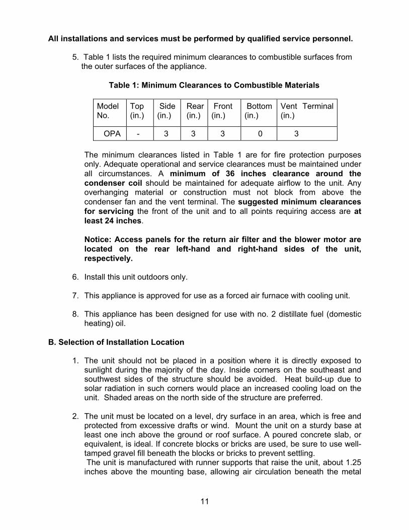
5. Table 1 lists the required minimum clearances to combustible surfaces from the outer surfaces of the appliance.
Table 1: Minimum Clearances to Combustible Materials
Model No.
Top (in.)
Side (in.)
Rear (in.)
Front (in.)
Bottom (in.)
Vent Terminal (in.)
OPA - 3 3 3 0 3 The minimum clearances listed in Table 1 are for fire protection purposes only. Adequate operational and service clearances must be maintained under all circumstances. A minimum of 36 inches clearance around the condenser coil should be maintained for adequate airflow to the unit. Any overhanging material or construction must not block from above the condenser fan and the vent terminal. The suggested minimum clearances for servicing the front of the unit and to all points requiring access are at least 24 inches.
Notice: Access panels for the return air filter and the blower motor are located on the rear left-hand and right-hand sides of the unit, respectively.
6. Install this unit outdoors only. 7. This appliance is approved for use as a forced air furnace with cooling unit.
8. This appliance has been designed for use with no. 2 distillate fuel (domestic
heating) oil.
B. Selection of Installation Location
1. The unit should not be placed in a position where it is directly exposed to sunlight during the majority of the day. Inside corners on the southeast and southwest sides of the structure should be avoided. Heat build-up due to solar radiation in such corners would place an increased cooling load on the unit. Shaded areas on the north side of the structure are preferred.
2. The unit must be located on a level, dry surface in an area, which is free and
protected from excessive drafts or wind. Mount the unit on a sturdy base at least one inch above the ground or roof surface. A poured concrete slab, or equivalent, is ideal. If concrete blocks or bricks are used, be sure to use well-tamped gravel fill beneath the blocks or bricks to prevent settling. The unit is manufactured with runner supports that raise the unit, about 1.25 inches above the mounting base, allowing air circulation beneath the metal

All installations and services must be performed by qualified service personnel.
12
surfaces. This clearance helps to promote air circulation under the base that allows the unit to be mounted on combustible materials. This clearance also helps to reduce metal corrosion caused by a buildup of moisture under the appliance.
3. The cooling system condenser must have an unrestricted supply of air for
efficient cooling.
4. The cooling system fan discharges air, upward through the top grill. For this reason, this appliance should not be located under an overhang or any other obstruction to airflow that would redirect the heated discharge air back into the condenser. The appliance should be located as illustrated in Figure 1, below.
Figure 1: Selection of Appliance Installation Location
For proper and safe operation of this appliance, ensure that adequate clearances around air openings into the burner compartment and the

All installations and services must be performed by qualified service personnel.
13
condenser coil area are maintained. These openings are not to be blocked, or restricted, in any manner.
5. Measures should be taken to prevent the entry of corrosive chemicals or vapors to the combustion and ventilation air supply. Such chemicals include, but are not limited to, chlorinated and/or fluorinated hydrocarbons. These substances are found in refrigerants, aerosol propellants, dry cleaning fluids, degreasers, and removers. Other harmful compounds may come from acids, salts, bleaches, air fresheners, cements, and glues. Do not store or use these chemicals for long periods of time in close proximity to this appliance. Vapors from such products can form corrosive compounds when burned in a flame. These compounds promote rapid corrosion of the burner, combustion chamber, heat exchanger, and the vent terminal. Rapid or excessive corrosion will significantly reduce the useful life of the appliance.
6. Refer to the following section, Venting of Combustion Products, for additional installation location restrictions.
C. Venting of Combustion Products
: This appliance is designed to directly vent combustion products
into the atmosphere through, and using only, the supplied vent terminal. Do not attempt to attach a vent connector or a vent system to, or in place of, the supplied vent terminal. The appliance should be installed in a location such that heavy snow accumulation will not excessively restrict the flow of flue (combustion) products from the unit. The vent terminal should not be located in a position where ice buildup could block the discharge of flue products. If these conditions occur, the performance of the heating system will be adversely affected.
Choose an installation location where the vent terminal does not discharge over sidewalks, walkways, and patios. These areas may become slippery when wetted by water vapor in the flue products.
Combustion products must not be allowed to accumulate within a confined space and recirculate back into the combustion system. Recirculation of combustion products promotes poor combustion. In severe cases, it may lead to sooting of the combustion chamber and heat exchanger, or to nuisance shutdowns of the heating system.

All installations and services must be performed by qualified service personnel.
14
In addition, long term exposure of building materials to combustion products may cause discoloration of material surfaces and corrosion or degradation of materials. The preferred installation location will allow combustion products to freely escape the immediate area of the appliance and rapidly disperse into the atmosphere, without being drawn back into the appliance or a nearby structure. To prevent combustion products from entering a structure, the vent terminal must expel combustion products away from any point of entry. The minimum acceptable distances from the vent terminal to points of entry to a building are 4 feet horizontally from, and 1 foot above, or at least 4 feet below, any window, door, or gravity air inlet into the building. And, 3 feet or more above any forced air inlet to the building located within 10 feet of the terminal. Once the unit is installed in a suitable location, the installer must mount the vent terminal to the appliance. Two sheet metal screws are installed in the unit for this purpose. Refer to Figure 2 for a sketch of the correctly assembled vent terminal.
FIGURE 2: Vent Terminal Mounting Position
D. Condensate Drain This appliance is equipped with a ¾ inch, female, NPT coupling for connection of a condensate line to the evaporator drain pan. A condensate removal line should be fabricated and attached to the coupling, refer to Figure 3. The condensate drain line must be pitched downward to drain properly. The drain line can also be trapped and the condensate pumped to a suitable drain. If the drain line clogs, when the air conditioner is operating, the condensate tray under the evaporator coil will fill with water. As a result, water may enter the appliance housing and the supply air ductwork to the structure.

All installations and services must be performed by qualified service personnel.
15
Figure 3: Installation of a Condensate Drainage Line on the Evaporator Coil
Condensate from the evaporator is non-corrosive and may be disposed of in any appropriate manner. The drain connection should be sealed at the appliance housing to prevent air leakage from the supply air system. Pipe sealant should be used sparingly on all male pipe threads. Always consult and conform to the requirements of local plumbing codes.
E. Oil Tank and Piping
: All local codes and ordinances take precedence with regard to selection and installation of oil storage tank and oil supply (and return) lines. In the absence of local codes, all tanks and lines must be selected and installed according to the instructions in this manual and the Standard for the Installation of Oil-Burning Equipment, NFPA 31-1997, or the latest edition.
1. The use of black steel pipe and malleable iron fittings is recommended for
all fuel oil service lines. Never use galvanized steel piping or fittings for any fuel oil lines.
2. Where practical, provide rigid supports for the piping.
3. If the piping size in a run must be reduced, use reducing couplings only.
Avoid the use of reducing bushings.
4. Remove all pipe thread burrs and inspect the pipe for dirt or other foreign material prior to connecting. If present, remove any deposits in the piping and discard any excessively corroded piping.
All installations and services must be performed by qualified service personnel.
16
5. A readily accessible, design-certified, manual oil shutoff valve, with a non-displaceable rotor member, shall be installed in the fuel oil supply piping within 6 feet of the appliance.
6. A pipe union, or flanged connection, shall be provided downstream from
the manual oil shutoff valve to permit removal of the appliance oil pump. Pipe unions must be the ground joint type or flanged-jointed using a gasket resistant to the corrosive action of fuel oils.
7. Pipe dope or thread sealant design-certified to be resistant to the action of
fuel oils should be used on all threaded joints. Thread sealant should only be applied to the male member of a joint. The first two threads on the end of the male member of each pipe joint should be clean and free from thread sealant.
8. Connection of the oil supply piping to the appliance should be made from
the left-hand side of the burner, facing the burner compartment cover.
9. When tubing is to be used for fuel oil supply lines, use of continuous runs of heavy wall copper tubing is recommended. Avoid running tubing against any type of heating unit and across ceiling or floor joists. If possible, install the tubing under the floor.
10. Where tubing is used for fuel oil supply lines, insure the tubing contains no
kinks, sharp bends, or collapsed regions where the inside cross-sectional area of the tube is greatly reduced. These will excessively reduce the flow of oil.
11. Flared fittings should be used at all tube joints, when tubing is used for
fuel supply lines. Do not use compression fittings. Avoid the use of tube fittings in inaccessible locations.
Burners are equipped with a single-stage, fuel pump. This type of fuel pump, when connected with a supply line only, is satisfactory where the fuel supply is level with, or above the burner thus permitting gravity flow of oil to the burner. If the tank is above the burner, and gravity oil feed to the burner is permitted, a single line system may be used. The line should have a gradual slope downward of approximately 1/2 inch per foot, or more, from the tank to a point directly below where it is connected to the pump. Pitching the line upward toward the tank will help prevent the formation of air pockets in the line. NOTICE: An oil safety valve or a delayed-action, solenoid valve should be installed in the oil supply line of all gravity-fed systems. When the oil tank is located below the level of the burner, it is necessary to “lift” the oil to the burner. A return line should be connected between the fuel pump
All installations and services must be performed by qualified service personnel.
17
and tank. This requires insertion of the "by-pass" plug into the fuel pump. If the lift (vertical distance between the supply line inlet and the burner) exceeds approximately 10 feet, a two-stage pump should be installed with a return line. When a return line is used with either single or two-stage pumps, in-line air is automatically returned to the tank, making the oil pump and lines self-purging.
Underground tanks should be located outside the building. Installation of above ground tanks is permitted inside buildings, under certain conditions, as well as outside. Consult the Standard for Installation of Oil-Burning Equipment for restrictions. If permitted, connect the burner oil supply line near the base of the tank, opposite of the fill end. Connection at this point tends to flush older oil through and out of the tank. This helps to prevent the accumulation of rainwater and condensed water vapor in the tank, which can cause the tank to corrode. If the oil supplier does not already use oil additives, it is recommended that additives be used to emulsify any water accumulation in the oil.
F. Oil Filter It is strongly recommended that an oil filter assembly be installed in the oil supply line to the unit. Use an oil filter with the capacity to trap a 40-50 micron particle for all installations. Install the filter between the oil manual shutoff valve and the burner.
The filter cartridge should be replaced at least once a year. The filter body should be thoroughly cleaned before installing a new cartridge.
G. Burner Specifications And Performance
The appliance is supplied with two oil burner nozzles, one for the high-fire and one for the low-fire heat input rate. The model OPA has the low-fire, oil nozzle already installed in the burner by the factory. Table 2 gives the burner specifications and the estimated performance of the appliance operating under high and low fire conditions.

All installations and services must be performed by qualified service personnel.
18
Table 2: Burner Specifications and High and Low Fire Heating Performance
* Based on #2 fuel (domestic heating) oil having higher heating value of 140,000 BTU per gallon.
** Based on an assumed steady state, thermal efficiency of 80%.
For more specific burner information, consult the Model AFG Oil Burner Instruction Manual or contact Thermo Products, LLC. P.O. Box 217, North Judson, IN 46366. Phone no. 574-896-2133.
Heating Mode
Oil Pump Pressure (PSIG)
Oil Flowrate @ Nozzle
(GPH)
Heat Input Rate*
(BTUH)
Heat Output Rate** (BTUH)
Burner Model Number
Air Tube Combination
Nozzle Type
High Fire 130 0.75 105,000 85,000
Low Fire 120 0.6 85,000 67,000AFG-TP1501 AF35 BOSS
Simplex, 80 deg., hollow
cone

All installations and services must be performed by qualified service personnel.
19
H. Airflow Requirements and Sizing of Duct Work
The duct system must be sized and installed by a qualified installer or service person, following the design standards of the Air Conditioning Contractors of America (ACCA) or the American Society of Heating, Refrigeration, and Air Conditioning Engineers (ASHRAE). This furnace has been designed to operate against a maximum external static pressure of 0.4 in. W.G. This is equivalent to .2 in. W.G. supply and .2 in. W.G. return pressure drops.
1. Supply and return air ducts have to be furnished by the installer and run
between the appliance, which must be installed outdoors, and the interior of the structure the appliance serves. These ducts must be sealed to the casing of the appliance.
2. To reduce the transmission of vibration and noise to the duct system and to reduce flexure of the duct system due to thermal expansion and contraction, it is recommended that flexible joints be installed at the supply and return duct connections to the unit.
3. The return air duct system must equal the supply air duct system in the flow capacity (CFM) for a given pressure drop. Use a supplier's catalog for proper sizing of outlet and return air registers and grills to ensure that they meet the flow requirements of the run to which they are connected.
4. The duct system shall be sized to provide the maximum air flowrate (CFM)
required of the installation. Two common rules for determining minimum airflow in heating and cooling systems follow: a. For heating, 14 CFM of airflow are required per 1000 BTU/hr of heat
output, based on steady state operation and a 50° to 80° temperature rise. b. For cooling, 400 CFM of airflow are required per ton of air conditioning.
(For reference, a ton of A/C = 12,000 BTU/hr removed from the space.)
Refer to Example 1, in Appendix B: Calculations of this manual, for a sample calculation of how to determine the required minimum air flowrate.
5. Duct sizing is based upon both air velocity and pressure drop considerations.
When possible, current practice favors designing ductwork for lower air velocities. (For residences, a maximum air velocity of 800 FPM is suggested.) This results in quieter duct systems, systems which require less fan power (reduced operating costs), and less carefully constructed ductwork (lower initial costs). However, lower air velocities also result in larger duct sizes than necessary at higher velocities. In some cases, space restrictions may limit the ductwork to smaller than optimal sizes.

All installations and services must be performed by qualified service personnel.
20
6. The following method can be used to size ductwork when air velocities are
low to moderate.
a. Using a floor view of the residence, determine, or layout, the locations of the supply registers and the return air grills. (Generally, supply registers should be located close to sources of heat loss, i.e. windows and doors, around the perimeter of the building. Return grills should be located in central positions as far away from the supply registers as practical.)
b. Find a location for the appliance outside the building that minimizes the
amount of ducting required to connect the appliance to the supply and return air duct systems. Consider issues of access to the oil supply and electrical service, required service and venting clearances, exposure to sunlight, and operating noise when selecting this location.
c. Plan an efficient layout for the ductwork connecting each of the supply
air registers in the supply system to the unit. Plan and layout ductwork connecting each of the return air grills in the return system to the unit. Measure or estimate the length of duct between each register and grill.
d. Select values for the airflow through each register and grill. e. Select values for the pressure drops of both the supply and return air
systems. Each branch of the supply (or the return) air system will have this pressure drop. The total pressure drop of the supply and return air systems added together cannot exceed the maximum external static pressure that can be supplied by the appliance blower.
f. Determine the required flowrate for each branch of the supply and return
air systems. The total air flowrate, by adding the air flowrate of each branch of the supply system, must equal the minimum required air flowrate (refer to part 3, above). Likewise, the air flowrate of each of the branches of the return air system must sum to the required minimum flowrate.
g. Using the selected air flowrates for each component of the duct system
and manufacturer’s literature, or published literature on duct system pressure drops, the pressure drop for each component in the duct system can be estimated. (Chapter 32 of the ASHRAE Handbook – Fundamentals is an excellent source of duct system design principles and pressure drop data.) Conversely, for a specified type of fitting, it is also possible to determine the required size or diameter of the component for a specified pressure drop and flowrate.

All installations and services must be performed by qualified service personnel.
21
h. The resistance of the take-off and the outlet register (or return grill) should then be summed together to determine the total pressure drop for each branch. This value should be close to the assumed value for the pressure drop of the system. If it is not close, then flowrates for each branch must be adjusted, or the design of the duct system must be altered, to give the proper pressure drops. Usually, the cross-sectional area of the ductwork should be changed in order to adjust the pressure drop to a suitable value.
Refer to Example 2, in Appendix B: Calculations of this manual, for a sample calculation of how to use this method for sizing the supply side ductwork for a residence.
Table 3 shows the air handling capacities of 100-ft. lengths of circular and rectangular ductwork based on a 0.1 in. W.G. static pressure drop. The first column to the right is the air flowrate and the second is the required diameter for a circular duct. The third column is the required cross-sectional area of the duct and the other columns to the left are rectangular ducts with sufficient cross-sectional area to handle the flow at the specified pressure drop. [For lengths of ductwork less than 100 ft., simply multiply 0.1 in. W.G. by the ratio of the actual duct length (in feet) over 100 ft. for the approximate pressure drop.] Use the supplier’s catalog for proper sizing of outlet air registers and return air grills to insure that they provide the required flowrate at the desired pressure drop.

All installations and services must be performed by qualified service personnel.
22
Table 3: Suggested Duct Sizes for Homes, Quiet Offices, Or Similar Installations (Based on a 0.1 in. W.G. static pressure drop per 100 ft. of duct.)
7. The supply and return air ducts, or flexible joints, should be carefully secured and sealed to the appliance housing to prevent air leakage from, or into, the duct system. For best performance, insulate the outside surfaces of the ducts to reduce heat loss from, or heat gain to, the ducts. The insulation system should be carefully selected and installed to minimize water and moisture absorption by the insulation.
All installations and services must be performed by qualified service personnel.
23
8. As a final step in the installation, the appliance must be adjusted to deliver a temperature rise within the range of 50° to 80°F. Adjust the blower motor speed to obtain a temperature rise within the acceptable range. The required blower speed will depend on the airflow resistance of a supply and return air duct systems.
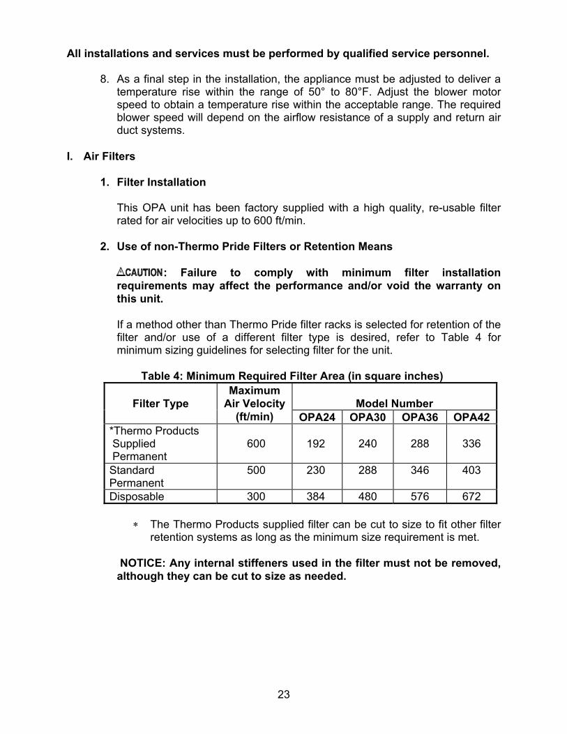
I. Air Filters
1. Filter Installation
This OPA unit has been factory supplied with a high quality, re-usable filter rated for air velocities up to 600 ft/min.
2. Use of non-Thermo Pride Filters or Retention Means
: Failure to comply with minimum filter installation
requirements may affect the performance and/or void the warranty on this unit.
If a method other than Thermo Pride filter racks is selected for retention of the filter and/or use of a different filter type is desired, refer to Table 4 for minimum sizing guidelines for selecting filter for the unit.
Table 4: Minimum Required Filter Area (in square inches)
Model Number
Filter Type
Maximum Air Velocity
(ft/min) OPA24 OPA30 OPA36 OPA42*Thermo Products Supplied Permanent
600 192
240
288
336
Standard Permanent
500 230 288 346 403
Disposable 300 384 480 576 672
∗ The Thermo Products supplied filter can be cut to size to fit other filter retention systems as long as the minimum size requirement is met.
NOTICE: Any internal stiffeners used in the filter must not be removed, although they can be cut to size as needed.
All installations and services must be performed by qualified service personnel.
24
J. Electrical Wiring
: This appliance must be grounded in accordance with local codes, or in the absence of local codes, with the National Electrical Code, ANSI/NFPA 70-1999, or the latest edition.
: Waterproof type connectors must be used when connecting
electrical power and control wiring to the unit to prevent moisture from being drawn into the unit during operation.
All wiring must conform to the provisions of local codes or, in the absence of local codes, with the provisions of the National Electrical Code, ANSI/NFPA 70-1999, or the latest edition, and this instruction manual. This appliance requires 208-240 VAC, 60 Hz, single-phase power. Refer to Table 5 for typical electrical current draws of the individual appliance motors, recommended sizes for over-current and short circuit devices, and minimum recommended field wiring sizes. Electrical service must be brought to the unit from a circuit breaker, or fused disconnect switch, in accordance with local codes. The disconnecting switch must be located reasonably close to and within sight of the unit. Three-wire service, two “hot” leads (L1 and L2) and a neutral (N), plus a ground conductor, is required. Connect power to the appliance control system at the junction box in the burner compartment. (A knockout fitting is provided on the exterior of the burner compartment for this purpose.) A ground wire must be connected to the grounding lug, or screw, marked “Equipment Ground”, in the junction box.
Field wiring of power circuits to the appliance should consist of copper conductors rated for at least 240 VAC with an insulation temperature rating of at least 75°C temperature rise. Depending upon code requirements, rigid or flexible conduit is recommended, and may be required. Connect the electric power supply as shown in the wiring diagram located on the inside of the burner compartment cover, or in this manual. The cooling system operates on 208-240 VAC electric power, from supply wires L1 and L2. The heating system operates on 120 VAC electric power, from supply wires L1 and N.

All installations and services must be performed by qualified service personnel.
25
Typically, control wiring between the outdoor appliance and the indoor thermostat, and if used, electronic air cleaner or humidifier, will be required. Field wiring of control circuits should consist of copper conductors rated for at least 240 VAC with an insulation temperature rating conforming to Type T wire, 35°C temperature rise. Depending upon code requirements, rigid or flexible conduit is recommended, and may be required. Make connections between the thermostat, and electronic air cleaner or humidifier (if used), and the fan control module, inside the burner compartment. Consult the wiring diagram for the appropriate connection points on the thermostat and the fan control module.
Table 5: Typical Electrical Requirements for Various OPA Models
Wire size selections in Table 5 are based upon Table 310-16 of the National Electrical Code for three copper conductors, with insulation rated for 75 degrees Celsius, contained in raceway at 30 degrees Celsius. For other wire insulation temperature ratings and ambient conditions, refer to the National Electrical Code for the minimum wire sizing requirements. NOTICE: Before the unit is started, the installer and/or electrician must check the following items.
1. Check every electrical connection of “push-on” or “screw-on” type terminals to
ensure that all wires and wire connectors are firmly secured. A loose terminal can cause poor flow of electrical power to motors and to the refrigeration compressor. This may result in very high current draws by these components. If great enough, high current draw will cause blown fuses, burned wires and contactor points, and pre-mature motor or compressor failure. Each electrical connection has been factory checked, however, connections may loosen, due to vibration, while the appliance is in transit. Please be certain that all electrical connections remain tight.
2. Review wiring diagram for proper routing and connection of all field wiring.
ModelPotential/Frequency
/No. of Phases (V/Hz/Ph)
Compressor Running
Load Current
(Amps) @ 200 VAC
Compressor Locked Rotor
Current (Amps) @ 200 VAC
Condenser Fan Full
Load Current
(Amps) @ 200 VAC
Supply/Return Air Blower Full Load Current
(Amps) @ 115 VAC
Oil Burner Assembly Full Load Current
(Amps) @ 115 VAC
Maximum Time Delay Type Fuse or Inverse
Time Circuit Breaker Size
(Amps)
Recommended Time Delay
Type Fuse or Inverse Time
Circuit Breaker Size (Amps)
Minimum Recommended
75 deg. C. Copper Power
Wiring Size (AWG)
OPA24 9.3 47 25 25 12OPA30 13.6 61 35 30 10OPA36 15 73 40 35 8OPA42 18.4 95 50 35 8
11 5.8208-240/60/1 2.1

All installations and services must be performed by qualified service personnel.
26
3. All wiring sizes must comply with local codes or the National Electrical Code. To minimize voltage drop to the appliance, the next larger size wire should be used when long wiring runs, in excess of 100 ft., are employed. Refer to the wiring diagrams when wiring or servicing.
NOTICE: Proper operation of the heating section of this unit depends upon correctly connecting the electrical power source. The hot leg, L1, of the supply circuit must be connected to the black line lead and the neutral leg, N, to the white line lead in the burner compartment junction box. All ungrounded circuit conductors must be broken by the disconnecting switch to prevent the hazard of electrical shock when servicing this appliance. In the event a circuit breaker trips or a fuse blows as a result of the operation of this appliance, investigate the appliance electrical system to determine the cause. Correct any electrical faults and abnormal conditions before putting the unit back into operation. Do not put in a larger fuse and do not exceed maximum fuse size listed on the rating label in order to temporarily “fix” the problem. The rating label is located on the inside of the burner compartment cover. The appliance control system contains a 15 amp. time-delay type fuse to protect the heating system control circuitry. The control fuse is located within the junction box, which is located in the burner compartment. In the event the fuse blows, replace the fuse with one of equivalent type and rating. 1. Electronic Air Cleaner (EAC) and Humidifier Installation
The standard control system for the appliance does not have the ability to directly control the operation of an electronic air cleaner or a humidifier. If these devices are used, a means to initiate and discontinue their operation must be provided external to the accessory if such means is not provided internally. Typically, an airflow sensing control is installed in the duct system to determine operation of the furnace and automatically activate (and also deactivate) the EAC or humidifier. If the control system contains the Honeywell brand model ST7997 electronic fan timer, this unit has designated terminals to control the operation of an electronic air cleaner and/or humidifier. These terminals provide line voltage for the control of these accessories, refer to Figure 4.

All installations and services must be performed by qualified service personnel.
27
Figure 4: The Fan Control Module
NOTICE: It is important to confirm that the operating voltage of the humidifier or EAC being installed matches the output of this control. If not, a field supplied relay or transformer may be necessary to provide the proper control and supply voltage for the accessory being installed. Refer to the manufacturer’s instructions for the humidifier or EAC for additional information.

All installations and services must be performed by qualified service personnel.
28
2. Thermostat Anticipator Setting
Proper control of the indoor air temperature can only be achieved if the thermostat is calibrated to the heating and/or cooling cycle. Calibration will help to produce a more constant indoor temperature by adjusting the length of the heating/cooling cycle to fit the application. A vital consideration of this calibration is related to the thermostat heat anticipator.
The proper thermostat heat anticipator setting is 0.1 ampere. To increase the length of the cycle, increase the setting of the heat scale; to decrease the length of the cycle, decrease the setting of the heat scale.
Anticipators for the cooling operation are generally pre-set by the thermostat manufacturer and require no adjustment.
Anticipators for the heating operation are of two types, pre-set and adjustable. Those that are pre-set will not have an adjustment scale and are generally marked accordingly. Thermostat models having a scale as shown in Figure 5 must be adjusted to each application.
Figure 5: Heat Anticipator Adjustment Scale
In many cases, this setting can be found in the thermostat installation instructions. If this information is not available, or if the correct setting is questioned, the following procedures should be followed:

All installations and services must be performed by qualified service personnel.
29
Preferred method of adjustment: Using an analog ammeter on the lowest scale, such as an Amp Check, connect the meter across terminals “R” and “W” on the sub-base (“RH” & “W” on an isolating thermostat sub-base). If the reading is too low to move the needle on to the measurement scale of the instrument, proceed as follows.
i. Wrap 10 loops of single strand, insulated, thermostat wire around the
prongs of an ammeter, refer to Figure 6. Set the scale to the 1 to 5 or 1 to 6 amp. scale.
Figure 6: Analog Ammeter w/ Wire Loops to Boost Reading
ii. Connect the bare ends of this wire jumper across terminals “R” and “W” on the sub-base (“RH” and “W” on an isolating thermostat sub-base). This test must be performed without the thermostat attached to the sub-base.
iii. Let the heating system operate in this position for about one minute.
Read the amp meter scale. Regardless of the value of the meter reading, divide the value by 10 (for 10 loops of wire).
This formula can be used to calculate the correct setting for the adjustable heat anticipator:
Ammeter reading = Anticipator Setting. No. of wire loops

All installations and services must be performed by qualified service personnel.
30
Or in this case,
_2.5 A. = 0.25 A. (Anticipator Setting) 10 iv. Adjust the position of the anticipator indicator to match the calculated
ammeter setting. If a slightly longer cycle is desired, the pointer should be moved to a higher setting. Slightly shorter cycles can be achieved by moving to a lower setting.
v. Remove the meter jumper wire and reconnect the thermostat. Check
the thermostat in the heating mode for proper operation.
If a digital ammeter is used, read the current draw directly from meter. (Steps 1 through 3 are not required.) The meter reading is the correct anticipator setting.
3. Blower Motor Speed Selection
: Turn off the electrical power to the unit, before attempting to change supply air blower speed wiring.
In order to obtain the required supply air flowrates in both the heating and cooling modes of operation, it may be necessary to reset the blower motor speeds. The blower motor is located behind an access panel along the right-hand rear side of the unit. To adjust fan speeds, it is necessary to remove this panel and physically change the wiring connections at a terminal block, mounted on the blower housing. There are four blower speeds available; high, medium high, medium low, and low. The terminal blocks will be marked with the symbols, “H”, “MH”, “ML”, and “L”, respectively, to indicate these speeds, refer to Figure 7. In addition, the left most terminal block will be marked with the symbol “C”, for common. A white wire should always be connected to terminal block marked “C”. The black wire controls the blower speed during the cooling cycle. The blue wire controls the blower speed during the heating cycle. The black and blue wires may be connected to any of the four terminals. Change the position of the wires on the terminal blocks to set the desired blower speed for each mode of operation. (Typically, two of the blower speeds will not be used.)

All installations and services must be performed by qualified service personnel.
31
Figure 7: Blower Motor Terminal Blocks & Wiring
All installations and services must be performed by qualified service personnel.
32
IV. STARTUP PROCEDURES A. Heating System
1. Initial Startup:
: Turn off power to furnace. Before the oil piping system is placed into service, it must have been leak tested by a qualified heating contractor.
: For initial start-up of the appliance after installation, it may be
necessary to purge the air out of the oil line. A qualified heating contractor should do this.
Review the following items before the initial startup. It may be helpful to review the Sequence of Operations in Appendix D of this manual, also. a. Check all wiring for loose connections and proper hook-up. Refer to the
connection diagram.
b. Leak test all field oil piping connections. Generally, this will involve pressurizing the oil piping with air while being careful to isolate the oil tank at high test pressures. A qualified heating contractor should perform this service.
c. Check to see that the vent terminal is correctly installed and the terminal
openings are clear and free from blockage.
d. Make sure the air filter is in place and relatively clean of dirt and debris.
e. Make sure the thermostat is set in the heating mode of operation.

All installations and services must be performed by qualified service personnel.
33
Operating Instructions:
i. STOP! Read the safety information above. ii. Set the thermostat to the lowest setting.
iii. Turn off all electric power to the appliance.
iv. This appliance is equipped with an ignition system that
automatically lights the burner. Do not try to light the burner by hand.
v. Rotate the manual oil shutoff valve to the “ON” position.
vi. Turn on the electric power to the appliance.
vii. Set the thermostat to the desired setting.
viii. If the appliance will not operate, call your qualified service
technician or oil supplier.
To Turn Off Oil to Appliance:
i. Set the thermostat to the lowest setting and set the operating mode switch to “OFF”.
For Your Safety Read Before Operating:
: If you do not follow these instructions exactly, a fire or explosion may result causing property damage, personal injury or loss of life.
• This appliance does not have a pilot light. It is equipped with
an ignition system that automatically lights the burner. Do not attempt to light the burner by hand.
• Do not use this appliance if any part has been under water.
Immediately call a qualified service technician to inspect the appliance and to replace any part of the control system and any oil control that has been under water.

All installations and services must be performed by qualified service personnel.
34
ii. If service is to be performed, turn off the electrical power to the appliance.
iii. Turn the manual oil shutoff valve to the “OFF” position.
2. Adjustment of Burner Combustion:
: Maximum gross stack temperature must not exceed 550°F (288°C) under any circumstances.
: Do not run the oil pump dry for more than five minutes, as irreparable damage may result.
NOTICE: Read the burner operation and service instructions, Model AFG Oil Burner Instruction Manual, before continuing.
To initially adjust and successfully service the oil burner in the appliance heating section, the following test instruments are required:
• A smoke density measuring and rating device, • A carbon-dioxide (CO2) or oxygen (O2) analyzer,
• A flue gas temperature measuring device (e.g., thermocouple or
thermister probe with readout device),
• An analog or digital multimeter, and
• An oil pressure gauge capable of reading 0-150 PSIG.
To initially fire the oil burner, proceed in the following manner.
a. Turn the disconnecting switch, which provides power to the appliance, to the "OFF" position.
b. Set the room thermostat above room temperature.
c. Verify the oil tank is filled with sufficient fuel oil to operate the
appliance.
d. Open all valves in the oil supply line to the burner.
e. Remove the burner compartment cover from the appliance.

All installations and services must be performed by qualified service personnel.
35
f. Open the inspection cover on the upper mounting plate above the burner.
g. Turn the disconnecting switch to “ON”.
h. Prime the pump to remove air in the oil supply line.
i. When ignition is established, make a preliminary burner air
adjustment to attain a clean combustion flame. Generally, the burner bulk air band should be about 3/16 inch open and the opening of the burner air shutter set in the range of “2” to “7”, refer to Figure 8.
Figure 8: Preliminary Adjustment of Burner Air Band and Air Shutter j. Replace the inspection cover above the burner.
k. After the appliance is warmed up to a steady state condition (about
15 minutes), the final burner adjustment should be made using combustion instrumentation for smoke, carbon dioxide (CO2) or excess oxygen (O2), and flue gas temperature. In order to achieve the most efficient combustion, the following steps must be taken:
i. SMOKE: A smoke sample should be drawn from the heat
exchanger flue passageway, which is covered by the vent terminal. (Remove a large machine screw from the front face of the vent terminal for direct access to the flue through the opening.) If the first smoke reading is zero (0), close the air band, or shutter, on the burner until a trace smoke reading is measured.
All installations and services must be performed by qualified service personnel.
36
NOTICE: To achieve proper combustion and the efficiencies listed in sales brochures, instruments must be used to secure CO2 or O2 readings.
ii. CARBON DIOXIDE (CO2) OR OXYGEN (O2): Take a CO2 sample
from flue passageway. It is possible to achieve readings of up to 14% CO2 (or 2% O2 ), but it is better to have a slightly lower CO2 (or higher O2) reading with zero smoke measured. To achieve a lower CO2 reading, open the air band, or shutter, on the burner until zero smoke is measured.
For example, if a 13% CO2 (or 3.5% O2) is recorded at a trace of smoke, open the air shutter until zero smoke is measured with a 12% CO2 (or 4.5% O2).
Adjustment of the burner to achieve a slightly lower CO2 reading is recommended, although it slightly reduces combustion efficiency, to keep the heating system within normal operating conditions though external conditions may vary. Some “out-of-spec” conditions which may adversely affect burner performance are, low oil supply temperature, dirty (contaminated) oil, low heating content (BTU/gal) oil, cold heat exchanger surfaces, and downdraft conditions. By adjusting the burner in this manner, an operational tolerance is established allowing the burner to function well, even under less than ideal conditions. This results in less service and maintenance during a heating season.
iii. FLUE GAS TEMPERATURE: The flue gas temperature will vary to
some extent depending on the heat input rate, duct design, and the amount of air flow across the heat exchanger. The suggested minimum net flue gas temperature is 3500 F, and the maximum gross flue gas temperature is 5500 F. The lower the flue gas temperature, the higher the heating efficiency. However, stack temperatures under 3500 F may result in condensation of water vapor in the flue gases, which in turn promotes corrosion of the heat exchanger.
iv. TEMPERATURE RISE: Temperature rise is equal to the supply air
temperature minus return air temperature. Under steady state operating conditions, the temperature rise across the heating section should be approximately 650F. A higher temperature rise will slightly lower the heating efficiency. A lower temperature rise will slightly raise efficiency, but may cause condensation.

All installations and services must be performed by qualified service personnel.
37
The supply air temperature should be measured in the supply air trunkline approximately 12 inches downstream of the supply air outlet of the appliance.
NOTICE: Minimum temperature rise is 500 F.; maximum temperature rise is 800 F.
l. After final adjustments are completed, tighten all screws to fix the
positions of the burner air band.
m. Check for the presence of oil leaks. Correct any oil leaks found.
n. Reassemble the burner compartment cover.
o. Start and stop the unit several times while checking for proper ignition of the burner. The flame should ignite and stabilize without any significant rumbles or pulsations.
3. Adjustment Of Heat Input Rate This appliance was shipped from the factory with one, fixed, main burner nozzle sized to produce the low-fire input rate using no. 2 fuel oil at the pump pressure shown on the rating label. The input rate can be changed to the high-fire by switching to the larger burner nozzle and increasing the pump pressure. The main burner oil nozzles for this unit were selected based upon the following assumed characteristic values of the fuel oil suitable for use with this appliance design:
• For no. 2 distillate fuel (domestic heating) oil having a higher heating value of 140,000 BTU per gallon and a specific gravity of 0.88 @ 60 deg. F. (or “gravity” of 30 deg. API @ 60 deg. F.).
It is possible to make minor adjustments to the heat input rate by adjusting the pump pressure. Sizeable changes in input rate (especially reductions) should be made by replacing the burner nozzle. To adjust the pump pressure to the main burner:
a. With the oil shut off, remove the 1/8 in. NPT threaded pipe plug located on the lower rear side of the oil pump, refer to Figure 13. Attach a pressure gage, capable of measuring pressure in pounds per square inch gage, PSIG, in this opening, on the discharge side, of the oil pump.
NOTICE: It may be necessary to remove the oil pump to attach the plumbing required to connect a pressure gage to the pump.

All installations and services must be performed by qualified service personnel.
38
b. Turn on the fuel oil and cause the appliance to activate the heating section by answering a “call for heat”.
NOTICE: It may be necessary to bleed air from the oil line before the burner can be fired.
c. Allow the heating section to operate for 10 to 15 minutes.
d. Note the oil pressure at the pump.
e. To adjust the pressure, use a common screwdriver to turn in the pressure
adjustment screw, located on the upper front of the oil pump body.
f. Allow the fuel flow rate to stabilize for a moment. Recheck the oil pressure.
g. If required, repeat the oil pressure adjustment again.
h. When the input rate adjustment has been completed, shut off the fuel oil to
the appliance. Remove the pressure gage. Reinstall the pipe plug using a thread compound resistant to the action of LP gases and fuel oil.
NOTICE: It may be necessary to bleed air from the oil line before the burner can be fired.
To insure the combustion air supply is adequate, it is now necessary to repeat the steps in the previous Initial Burner Adjustment section of this manual.
4. Setting Supply Air Temperature Rise
: To avoid injury from moving parts or electrical shock, shut
off the power to the appliance before removing supply air blower compartment door and servicing this appliance.
All OPA models are designed and wired at the factory for a blower speed during heating that should result in an approximate temperature rise of 65°F. The temperature rise through the heating section, for any given blower speed, may vary depending on a number of factors. A few of these factors are variations in, the actual resistance of the duct system to airflow at any time, the return air temperatures, and the fuel oil heating value. Also, fouling of the heat exchanger surfaces will reduce temperature rise. In general, a lower temperature rise through the heating section will result in higher heating efficiency.
Temperature rise = supply air temperature - return air temperature.

All installations and services must be performed by qualified service personnel.
39
After 15 to 20 minutes of continuous operation, the temperature rise through the furnace must fall within a range of 50° to 80° F. If the outlet or supply duct temperature is too high, check to make sure the return air filter is clean, the return air registers are free from obstruction, the outlet registers are properly adjusted and clear, and the supply and return air ducts are open.
The circulating air blower is not moving enough air if the supply air temperature is still too high. Before proceeding further, turn off the power supply to the appliance and remove the blower access door. The speed of the blower must be increased by changing from a lower motor speed tap to a higher speed tap, refer to Figure 10.
5. Checkout Procedure
Before any system of oil piping is finally put into service, it shall be carefully tested to assure that it is “gas-tight”, as indicated in the Heating System Initial Startup section of this manual.
NOTICE: All controls on the unit should be checked for proper functioning prior to the qualified service personnel leaving the job site. Specifically the following should be checked:
a. With heating system in normal heating operation, check to make certain
blower will start and stop automatically under control of the indoor thermostat.
b. Check safety limit control as follows:
i. Shut off incoming power. ii. Block return air opening or disconnect blower motor leads.
iii. Restore power to appliance.
iv. In the heating mode, set the thermostat above room temperature
producing “a call for heat”.
v. When high air temperatures are reached within the heating section, the high limit control should act to shutdown the burner.
vi. Shut off the electrical power.
IMPORTANT: Remove blockage or reconnect blower motor and restore power.

All installations and services must be performed by qualified service personnel.
40
c. Make certain the thermostat will automatically start and stop the appliance.
NOTICE: Heat exchanger oil will burn off on initial firing creating an unpleasant odor. To prevent this odor from occurring more than once, it is suggested the heating section be allowed to run for 30 minutes, or until odor has dissipated.

All installations and services must be performed by qualified service personnel.
41
B. Cooling Section
1. Initial Startup:
: Refrigerant is under pressure. Guard against refrigerant spraying into the face or on skin. Always wear protective equipment, i.e. safety glasses or goggles and gloves when working with refrigerant.
: Do not under any circumstances heat the refrigerant cylinder with a torch or by any other means other than warm water. Excessive pressures generated in this manner may weaken the refrigerant container and result in an explosion!
: Do not attempt to operate the cooling section on a day when outdoor temperatures are 45°F or cooler.
On cool days (65°F or lower), attempts to operate the cooling section and take gauged pressure readings may be unsuccessful as unusually low pressure will be observed on the suction line. This type of operation may give the impression of an undercharged unit. This is not necessarily the case. A low refrigerant pressure reading may occur due to the combined action of the large condenser surface area and cold ambient air removing a large amount of heat from the refrigerant. As a result, subcooling of the refrigerant occurs and very low refrigerant pressures can be measured. Adding refrigerant in cold weather will result in an overcharged unit. During warm or hot weather, high ambient temperatures will greatly increase the refrigerant pressure which may then cause the high limit pressure switch to shutdown the unit. Due to the high probability of taking a false reading, suction line pressure should not be taken for test purposes when the outdoor temperature is below 70° F. When the outdoor air temperature is cooler than the indoor air temperature, refrigerant vapor will condense in the compressor. If the compressor is started when it contains liquid refrigerant, the lubricating oil in the crankcase will be diluted. Bearing damage may result under these conditions. In addition, if the compressor attempts to squeeze the liquid refrigerant, serious and permanent mechanical damage to the compressor can result. The appliance is equipped with gauge ports to connect both liquid and suction line pressure gauges. These ports are located near the base of the unit, inside the burner compartment. Refrigerant hoses must be the types that incorporate a “finger” to depress the valve core. Connections may be made to these ports at any time, even while unit is in operation. Follow EPA guidelines in connecting service equipment to refrigerant lines. For example, using quick connects and short service hoses is recommended to minimize refrigerant losses. Line pressures on an operating air conditioning unit will vary with outdoor temperatures. As outdoor temperatures rise, pressures will also rise. Refer to a

All installations and services must be performed by qualified service personnel.
42
pressure-temperature chart on the unit for approximate system line pressures at various temperatures.
The suction pressure is the most significant pressure reading. If a unit is suspected of having a low refrigerant charge, the unit should be recharged using the suction pressure as a guide. The unit is fully charged when proper suction pressure is obtained. Any additional refrigerant may cause damage or unintended problems. The pressure/temperature chart on the wiring diagram is to serve only as a guide. Pressures shown are realistic averages which will vary somewhat with changes in air temperatures, air flowrate across the evaporator and condenser coils and humidity – both inside and outside.
If a charge must be added to the system, connect to the suction service port of the service valve and add a vapor charge only while the system is operating. Addition of liquid refrigerant at the suction port may damage the compressor.
2. Definition of Superheat:
Superheat is extra heat added to refrigerant above the vaporization pressure/temperature of the refrigerant. A small amount of refrigerant superheat is usually beneficial and needed to help assure the best operation of the cooling system.
Superheat cannot be measured with a pressure gauge alone. Both pressure and temperature readings of the suction line are required to evaluate the amount of refrigerant superheating. The degree of superheating gives an indication of two important system-operating parameters. Superheat at the suction line outlet of the evaporator indicates the efficiency of the evaporator coil. Superheated vapor at the suction line inlet to the compressor insures that liquid refrigerant is not being pumped into the compressor.
Highly superheated vapor is also detrimental to system operation. The highly superheated refrigerant may overheat the compressor, resulting in premature failure and/or intermittent thermal cutout of the compressor. High superheat at the evaporator also indicates the evaporator is operating very inefficiently by vaporizing the refrigerant too quickly in the evaporator coil. High superheat at the evaporator results in some loss of the evaporator heat removal capacity.

All installations and services must be performed by qualified service personnel.
43
Startup of a new cooling system and checkout of an existing system should always include superheat measurements. Before measuring superheat, allow the system to operate under a load for approximately 15 minutes. A conditioned space load will usually provide enough heat for the evaporator to remove for at least this period of time. Operating the cooling system for 15 minutes allows the refrigeration system to stabilize, providing good operating pressures and temperatures. NOTICE: Do not attempt a superheat measurement when the ambient temperature is less than 60° F. Low loading on the cooling system will result in low or erroneous superheat measurements.
NOTICE: When adding or removing charge to fine tune the cooling system performance, allow 15 to 20 minutes of system operating time after each adjustment of the charge. After 15 to minutes of operation, a reliable superheat reading may be taken.
3. Evaporator Superheat:
To measure superheat at the evaporator, a suction pressure reading at the outlet of the evaporator would be desirable. Since most residential cooling systems (including Thermo Pride evaporators) do not provide a test port (sometimes referred to as a Schraeder port) at the evaporator, the suction pressure must be read at the suction inlet to the compressor. Typically, it would be necessary to compensate for the pressure drop through the line connecting the evaporator and the compressor. However, due to the close proximity of these components, the pressure drop will be small and can be neglected. A good resistive-type thermometer or thermocouple-based sensor should be used to measure the suction line temperature exiting the evaporator. On evaporators using thermal expansion valves, read the temperature directly under the expansion bulb, located on the side of the suction line exiting the evaporator.
Measure refrigerant temperature at the 2:00 or 10:00 positions on the outer surface of the evaporator suction tube. Wrap the thermometer or thermocouple with a rag, or insulation, to insure system airflow does not influence the temperature readings.

All installations and services must be performed by qualified service personnel.
44
Refer to Example 3, in Appendix B: Calculations of this manual, for a sample calculation of how to figure the degree of superheat for the evaporator. In general, Thermo Pride recommends an operating evaporator superheat of between 5° and 12°F.
4. Definition of Subcooling:
Subcooling is extra heat removed from refrigerant below the saturation pressure/temperature of the refrigerant. A small amount of refrigerant subcooling is usually beneficial and needed to help assure the best operation of the cooling system. Subcooling takes place in the condenser. It is a function of the amount of airflow into the condenser, the outside ambient air temperature, the refrigerant pressure into the condenser, and pressure drop through the condenser.
Refrigerant with low subcooling or saturated refrigerant may partially change back into vapor, or “flash to gas”, while flowing to the evaporator. The resulting gas bubbles can block or interrupt flow through refrigerant controls causing the evaporator to “starve” for liquid refrigerant. The consequences are poor evaporator efficiency, high superheat, and generally poor cooling of the conditioned space. Unless very well-insulated, long liquid lines from the condenser to the evaporator, specifically liquid lines exposed to high ambient temperatures, are prone to reduce refrigerant subcooling. To insure sub-cooled liquid refrigerant reaches the evaporator under all conditions, it is usually advisable to take subcooling measurements during the warmest part of the day. Test measurements taken during this time would provide results typical of the most adverse conditions under which the cooling system would operate. Installing a liquid line sight glass at the inlet to the evaporator is a simple, but effective, way to prove liquid is feeding the evaporator. If the sight glass shows all liquid flow without bubbles this is a good indication that the amount of subcooling is adequate.
5. Condenser Subcooling:
Before taking subcooling measurements, allow the system to stabilize through continuous operation for at least 15 minutes. To determine subcooling, measure the refrigerant pressure at the liquid line as it leaves the condenser. It is preferable to measure pressure of the liquid line at the evaporator, but most manufacturers, including Thermo Pride, do not include test ports (or Schraeder valves) at the evaporator. Typically, it would be necessary to compensate for the pressure drop through the line connecting the condenser and the expansion valve. However, due to the close proximity of these components, the pressure drop will be small and can be neglected.

All installations and services must be performed by qualified service personnel.
45
Once the liquid line pressure is known, the refrigerant temperature must be taken on the liquid line as it enters the evaporator. Use a good resistive thermometer or thermocouple protected with a rag or insulation. Subtract the measured temperature from the saturation temperature of the refrigerant. The result is the degree of refrigerant subcooling.
Refer to Example 4, in Appendix B: Calculations of this manual, for a sample calculation of how to figure the degree of subcooling for the condenser. In general, Thermo Pride recommends the evaporator operate with a subcooling of between 5° and 15°F.
6. Recommendations for Operation at Low Temperatures
If the cooling system will be operated with outdoor ambient air temperatures below 65°F, Thermo Pride strongly recommends the following modifications be made to the system to aid in promoting the longevity and durability of the compressor.
1. To help evaporate any liquid refrigerant that accumulates in the compressor,
a crankcase heater should be installed in the compressor.
2. A low temperature (45°F minimum) ambient control (contact) should be added to the 24-volt leg of the control circuit to the contactor coil. This contact should act to shutdown the cooling system in the event that outdoor temperatures drop below 45°F.
3. To assist the system in temporarily storing unneeded refrigerant charge, a
suction line accumulator should be installed in the system.
4. Test and confirm the compressor is receiving superheated vapor under the coldest of expected operating conditions. Adjust the superheat, if required.
These items will assist in preventing liquid floodback, flooded starts, and refrigerant migration to the compressor during off cycle. These situations are detrimental to the service life of the compressor.

All installations and services must be performed by qualified service personnel.
46
V. INSTALLER'S INSTRUCTIONS TO USER
After completing the installation, the installer shall inform and/or demonstrate to the homeowner:
1. The location of these instructions in the appliance. These instructions must be kept along with instructions for any accessories in the plastic pouch on the inside of the appliance.
2. The location and use of the manual oil shutoff valve and appliance electrical
disconnecting device. The end user must be instructed to always shut off the electric power to the appliance, before shutting off the oil supply.
3. The sequence of operation of the appliance.
4. The correct operation and maintenance of the appliance, as outlined in the
Homeowner/User Information and Routine Maintenance section of this manual.
5. That failure to maintain and operate this appliance in accordance with these
instructions could result in hazardous conditions, property damage, and bodily injury. It may also void the limited warranty on the appliance.
6. Review with and encourage the user to read the label reproductions and all
warnings and instructions outlined on the front cover and in Sections I, II, and III, of this manual.
7. Recommend the user have a qualified heating contractor inspect the entire
appliance at least once a year. Inform the user of the frequency of inspection required for each item in the Dealer Maintenance section of this manual.
8. Inform the user to maintain adequate clearances around air openings into the
appliance housing and not to block or restrict the entrance of air into the condenser coil or the burner compartment air openings.

All installations and services must be performed by qualified service personnel.
47
VI. DEALER MAINTENANCE
SAFETY DURING SERVICING AND INSPECTION
: Personal injury or property damage could result from repair or service of this appliance by anyone other than a qualified heating contractor. The user may only perform the activities described in the Homeowner/User Routine Maintenance section of this manual.
: To avoid injury from moving parts, or electrical shock, shut off the power to the appliance before removing blower compartment door and servicing this appliance.
: When servicing controls, label all wires prior to disconnecting. Reconnect any removed wires correctly. Wiring errors can cause improper and dangerous operation. Dangerous operation can result in injury or damage. IMPORTANT: Verify the proper operation of this appliance after any servicing is performed.
A qualified heating contractor should perform the following maintenance procedures at the beginning of each heating season. Correct any deficiencies at once. A. General Inspection
: Shut off oil and disconnect power before continuing w/ this
inspection.
1. Vent terminal - Visually inspect the terminal for restrictions, loose or missing fasteners, external damage, and carbon build-up. Clean the vent terminal and the screen(s) covering any opening in the terminal. Repair any minor damage. If necessary, replace a severely damaged or degraded vent terminal.
2. Burner – Visually check the burner, and below the burner, for indications of oil
leaks. Correct any, if found. Remove the burner and measure the ignition electrode gap. It should be set to 5/32 inch. Adjust it, if necessary. Clean any accumulation of dust, dirt, or debris from the air shutter or air band openings. If necessary, clean housing and blower wheel with a damp cloth. Use a vacuum to remove any lint or dust from motor assembly. Add a few drops of non-detergent oil to each of the motor lubrication holes.
3. Combustion Chamber - Inspect the liner for deterioration, oil and carbon build-up.
If the accumulation of oil or carbon is significant, this is a strong indicator that the burner is out of adjustment. Inspect the burner nozzle for partial blockage and

All installations and services must be performed by qualified service personnel.
48
excessive wear. Replace it, if required. Check and adjust oil pump pressure, if needed. Refer to Initial Heating System Adjustments section of this manual.
4. Heat Exchanger – Visually inspect the heat exchanger for excessive carbon
(soot) build-up. Refer to the Heat Exchanger section of the manual.
5. Oil Filter – Replace the supply line oil filter cartridge with a new filter of the same type and rating. Clean the body of, or mounting plate for, the oil filter.
6. Evaporator and Condenser Coils – Inspect both the evaporator and the
condenser coils for dust, dirt, debris, and insects lodged between the fins. Remove any foreign materials found using a vacuum cleaner with a brush attachment or a water spray from a garden hose. Carefully straighten any bent fins with a thin piece of wood or a fin comb.
7. Labels and Markings - Clean all appliance labels, markings, and instruction
plates, as necessary, and verify that all are still legible. Any illegible or missing markings must be replaced. Replacements can be obtained by contacting Thermo Products.
B. Heat Exchanger
: A qualified heating contractor must clean the heat exchanger. At least once a year, inspect the heat exchanger for evidence of corrosion, pitting, warpage, deterioration, and carbon (soot) build-up. A layer of soot on the inside of the heat exchanger will act as an insulator and reduce heat transfer, resulting in less heating efficiency. Also, look for loose or deteriorated gaskets and insulation around the flue pipe, the burner, and accessible areas of the heat exchanger. If this inspection indicates heat exchanger cleaning is necessary, follow the heat exchanger cleaning instructions below. 1. Disassembly to Access Heat Exchanger
To clean the heat exchanger, first turn off all electrical power to the unit. Next, remove the cleanout access panel inside the burner compartment to gain entry to the cleanout covers, refer to Figure 9.

All installations and services must be performed by qualified service personnel.
49
Figure 9, OPA Heat Exchanger Clean-out Ports and Related Components
Remove the clean-out covers. Also, remove the burner compartment cover, the burner, and the burner mounting plate. When removing the clean-out covers, special care must be taken not to damage the gaskets. Should any of the gaskets separate, show evidence of cracks or breaks, or otherwise be unable to provide the necessary seal, the gasket must be replaced before reattaching the clean-out covers, refer to Figure 10.

All installations and services must be performed by qualified service personnel.
50
With access to the inside of the heat exchanger through the burner area, cleanout openings, and vent terminal connection, it is now possible to use a long, flexible wire brush and an industrial type vacuum cleaner to remove any soot build-up.
NOTICE: A one inch (outside diameter) vacuum cleaner hose will fit into the radiator.
To vacuum and brush the horizontal drum of the heat exchanger, enter the drum through the clean-out openings in both directions.
2. Heat Exchanger Reassembly
After the heat exchanger has been cleaned, install the heat exchanger and reassemble the components to their factory produced state, in reverse order of disassembly and removal, refer to figures 9 and 10. Remount the burner being certain that the air tube is properly inserted into the chamber opening. If heavy soot deposits were found in the heat exchanger, this indicates that the burner may be out of adjustment. Reset the burner, as indicated under the Initial Burner Operation section.
Figure 10: View of OPA Heat Exchanger
Replace any damaged or corroded components. All gaskets and insulation must be inspected, and replaced, if they show any signs of damage.

All installations and services must be performed by qualified service personnel.
51
3. Operational Check
: Before troubleshooting, familiarize yourself with the start up and check out procedures
NOTICE: After reassembling the appliance, check for fuel oil leakage from the supply piping.
a. Check proper operation of the ignition system and for proper combustion.
b. Observe the main burner flame. If the flame appears strange or abnormal in
character, look for a component or components that were not reassembled correctly. If the components have been reassembled correctly, check for a blocked vent, malfunctioning combustion air blower or fuel pump, and partially blocked burner nozzle.
C. Electrical System
: When servicing controls, label all wires prior to disconnecting.
Correctly reconnect any wires removed during servicing. Wiring errors can cause improper and dangerous operation. Dangerous operation can result in injury or damage. 1. Check all wiring for loose connections and any signs of damage, or unusual
wear. Replace any damaged or frayed wiring and tighten any loose connections.
2. Use a voltmeter, or a multimeter, to check for adequate voltage at the field connections when the appliance operating.
3. Use an ammeter, or a multimeter, to check the current draws of the blower motor, burner assembly, and air conditioning compressor to assure they are not exceeding rating label current specifications for each component. Also, refer to Table 5 for electrical specifications on these components.
4. Check for correct operation and proper settings (if manually adjustable) of all controls.

All installations and services must be performed by qualified service personnel.
52
D. Supply/Return Air Blower Check in the blower compartment for dust, dirt, debris, and for the presence of insects. Remove any foreign material. Clean the blower wheel, housing, and compartment of dust and lint with a vacuum.
The blower motor has sealed bearings that are permanently lubricated. The blower motor bearings do not require oil or any type of additional lubrication.
E. Supply/Return Air Filter
A permanent-type air filter is provided in the return section of this unit. This filter should be inspected regularly. When the filter is dirty, it should be cleaned or replaced to assure proper heating/cooling system operation. Follow the cleaning, removal and replacement procedure below. 1. Filter maintenance procedure
The filter rack is located behind an access panel on the left-hand side of the unit, refer to Figure 12. Shut off the electrical power to the unit. Remove the screws retaining the access panel to the housing. Remove the access panel. Slide the dirty air filter out of the filter rack. Clean the filter by either vacuuming, rinsing with tap water, hosing, or dipping in an ordinary detergent solution. After cleaning and drying the filter, replace the completely dry filter in the rack. If the filter has a supporting mesh, the mesh side of the filter must be placed towards the furnace.
Figure 12: Location of the OPA Supply/Return Air Filter
2. Filter replacement
To ensure an adequate replacement filter is selected, should the filter require replacing, refer to Table 4, in Air Filters section of this manual, for the minimum filter areas required for different types of available filters.

All installations and services must be performed by qualified service personnel.
53
NOTICE: Remind the homeowner of the importance of monthly filter inspections during operation to ensure maximum operating efficiency.
F. Extended Appliance Shutdown
: Do not attempt to start burner when: • Primary reset has been engaged more than two times. • Excess oil has accumulated in the combustion chamber or beneath the
burner assembly. • The combustion chamber or the heat exchanger is full of fuel vapor. • The combustion chamber is very hot.
Should the appliance be shutdown or turned off for an extended period of time, several steps can be taken to help insure a smooth and reliable restart of the heating system.
ON SHUTDOWN:
1. Close oil supply (or manual shutoff) valve. 2. Disconnect all electrical power to the unit.
3. Fill the oil tank to reduce water condensation in the tank.
4. If the shutdown period will exceed one heating season, an oil stabilizer
should be added to the oil tank. Consult your oil supplier for recommendations.
ON STARTUP: 1. Have system inspected and started by a qualified heating contractor. 2. Check oil level in tank. If the tank has not been filled with fresh oil, inspect
the remaining oil for signs of contamination with water, algae, dirt or other impurities. If excessive, consult your oil supplier for recommendations.
3. Change the oil filter cartridge and clean the canister.
4. Set the room thermostat above room temperature.
5. Open all valves in the oil supply line.

All installations and services must be performed by qualified service personnel.
54
6. Open the inspection cover on the upper mounting plate.
7. Turn on the electrical power to start the burner. If the burner does not start,
immediately reset the manual overload switch on the motor (if so equipped) and the safety switch of the burner primary control. Bleed air from the fuel oil line as soon as the burner motor starts rotating. To bleed the fuel pump, attach a clear plastic hose over the vent plug, refer to Figure 13. Loosen the plug and catch the expelled oil in an empty container. Tighten the plug when all the trapped air appears to be purged. If the burner stops during bleeding, wait three to five minutes for the control safety switch to cool. Then manually reset the switch. Continue bleeding the line until the air is completely removed.
Figure 13: Location of Oil Pump Vent Plug
8. Follow the previous Initial Burner Operation procedures.
All installations and services must be performed by qualified service personnel.
55
VII. HOMEOWNER/USER INFORMATION AND ROUTINE MAINTENANCE
: Never burn garbage or refuse in this appliance. Never try to ignite oil by tossing burning papers or other material into the combustion chamber.
: Oil-fired appliances produced by Thermo Products are designed for burning No. 2 distillate (domestic heating) fuel oil. Never use gasoline or a mixture of oil and gasoline.
: Do not use this appliance if any part has been under water. Immediately call a qualified service technician to inspect the furnace and to replace any part of the control system and any oil control that has been under water.
: Should overheating occur, or the oil supply fail to shut off, shut off the
electrical power to the appliance, before shutting off the manual oil valve.
: The area around the appliance, including the top of the unit, must be kept clear and free of combustible materials, gasoline, and other flammable vapors and liquids.
I : The appliance vent terminal may be hot. If the terminal is hot, allow it to cool before touching it.
I : Do not attempt to make repairs yourself. Contact your local qualified heating contractor. Under normal conditions, this appliance will operate in either heating or cooling mode, depending upon the mode of operation set at the thermostat. The unit will cycle on and off automatically, as required, to maintain the air temperature within the residence as closely as possible to the thermostat setting. However, in rare cases, the unit may shutdown automatically during a normal cycle or may not operate under seemingly normal conditions.
If the unit will not operate in the heating mode, it may be possible to reactivate the unit by resetting one of the burner controls. To attempt resetting of the burner controls, follow this procedure.
1. Turn the thermostat temperature setting down and set the operating mode to
“OFF” or “COOLING”. 2. Remove the burner compartment cover.
3. Check to see if the LED on the burner primary (ignition) control module is
flashing at a rapid rate. If so, the control may have “locked out”. To recycle the control system, depress the reset button. Refer to Figure 14.

All installations and services must be performed by qualified service personnel.
56
4. Check to see if the high temperature limit switch reset button, on the burner
motor, has “popped out”. If so, the control has activated. To reactivate the control, depress the reset button.
5. Replace and secure the burner compartment cover.
6. Set the operating mode on the thermostat to “HEATING” and turn the thermostat
temperature setting up.
Figure 14: Location of Reset Buttons on the Burner Primary Control and the
Burner Motor
If this action does not reactivate the unit, contact a qualified service agency for assistance.
In general, if the thermostat is set in the heating mode, the heating system functions entirely automatically. However, under certain circumstances, the appliance may not be able to fire the burner. For instance, if the manual oil shutoff valve has been closed or the oil tank is out of fuel, the oil line may have air trapped in it. It will be necessary to purge the air by bleeding the supply line from the tank to the burner again for the heating system to operate. Refer to the instructions under the Extended Appliance Shutdown section of this manual. NOTICE: Thermo Products recommends that the user/homeowner, contact a qualified service agency for assistance in bleeding the fuel line(s) and lighting off the heating section.

All installations and services must be performed by qualified service personnel.
57
The following maintenance points should be reviewed periodically to assure the heating and cooling systems continue to function properly.
: Shut off unit and disconnect the power source before disassembling
the unit.
: Never operate the appliance without clean air filters in place.
: This appliance requires air for combustion, ventilation, and cooling. Do not block or obstruct air openings in the unit and the air space around the perimeter of the unit.
1. At least every three months, under normal usage conditions, check and clean all air
filters in the appliance and, if present, in the duct system. If excessively dirty air filters are not cleaned, or changed, poor system performance will result due to reduced airflow. Low airflow places unnecessary strain on the compressor, possibly causing the system to shutdown on the refrigerant high-pressure switch. Refer to Figure 16 for a sketch of the filter location.
2. Keep the outside condenser coil clean by carefully spraying the finned area with
plain water, from the inside of the coil outward. 3. Carefully remove any leaves, twigs, debris, trash, and insect or small animal nests/
homes from in and around any openings in the appliance housing.
4. Visually inspect the vent terminal for restrictions and blockages. With the heating system in operation, the vent terminal will be hot. Shut off the unit and allow the vent terminal to cool before removing any foreign materials from within the vent terminal.
5. Inspect the exterior of the appliance for signs of excessive heat such as
discoloration of materials, damage from rust or corrosion, or evidence of oil leakage. Pay special attention to the mounting base the appliance is resting upon. If the base is severely damaged, deteriorated, or unstable, shutdown the unit and call a qualified heating contractor for recommendations on repair or replacement of the base.
6. Do not allow the fuel oil tank to run completely empty. During the summer, keep the
tank full to reduce condensation of moisture on the inside surface of the tank. If the fuel tank runs completely dry, it may be necessary to bleed air from the fuel lines. Contact a qualified heating contractor to bleed the lines and restart the burner.
7. Check the supply and return air connections to the appliance to insure the seals
between the duct and appliance and the appliance and home are intact. Check the

All installations and services must be performed by qualified service personnel.
58
ducts for any signs of collapse, holes, or excessive corrosion. Repair or replace components as required.
8. It is advisable to wax the outer surface of the appliance housing yearly to provide the
surface finish protection from excessive degradation by sunlight and inclement weather. A good grade of automotive wax should be used to protect the finish.

All installations and services must be performed by qualified service personnel.
59
VIII. TROUBLESHOOTING
: Power must be disconnected before servicing.
Refer to the appendices of this manual for an electrical schematic, a connection diagram, flowcharts to assist in troubleshooting, product specifications, and a replacement parts list follow for this appliance. A. Heating System:
Qualified HVAC and cooling contractors must perform all service.
NOTICE: Before troubleshooting, familiarize yourself with the Initial Startup, Checkout Procedure, and Heating System Troubleshooting Flowchart.
To assist in troubleshooting the heating section of this appliance, it is equipped with an integrated safety and ignition control with diagnostics. These diagnostics include an indicator light that relays the operational status of the control and can help in diagnosing the condition of the flame sensor.
Diagnostic Features
The Honeywell brand model R7184P (or alternate R7997D) safety and ignition control module used on this unit continuously monitors the operation of the heating system. If an abnormal condition occurs, the LED light on the control will rapidly flash indicating the operational status of the unit. In event this control malfunctions, the entire control should be replaced. It is not field-repairable.
In the event of an operational failure of the burner system, the rate of flashes, if any, of the ignition control module LED should be noted, before turning off power to the unit. Otherwise, power to the heating section will be interrupted and the control LED will not furnish the diagnostic flashing. It may be necessary to restart the furnace and have the failure occur again. For the model R7184P, under normal operating conditions, the LED will be continuously lit while the burner is operating. For the model R7997D, the LED will be continuously flash at a low rate (approximately 2 seconds “on”, 2 seconds “off”) while the burner is operating. If either control has sensed a flame failure, which was uncorrected by initiating another trial-for-ignition, the control will cease ignition trials and shutdown the burner, or “lockout”. The LED will continuously flash at a high rate (approximately 1/4-second “on”; 1/4 second “off”, for the model R7184P, or approximately 1/2-second “on”; 1/2 second “off”, for the model R7997P) during the lockout mode. To initiate another trial-for-ignition, it is necessary to manually depress the reset button on the control module. I : If the appliance fails to relight after resetting the primary control twice contact a qualified service company. DO NOT continue to reset primary control.

All installations and services must be performed by qualified service personnel.
60
The operational condition of the flame sensor, or “cad cell”, can be checked by depressing the reset button on the control module, while the burner is operating. Count the number of flashes of the LED and compare them to the table below. Number of flashes Cad Cell Resistance (in ohms)
Model R7184P Model R7997D 1 ......................................... Less than 625 Less than 300 2 ......................................... 625 to 1250 300 to 600 3 ......................................... 1250 to 2500 600 to 1200 4 ......................................... 2500 to 5000 1200 to 5000
If it is necessary to troubleshoot the flame sensor independently of the burner primary, the following procedure may be used.
CAD CELL CHECKOUT PROCEDURE: 1. Stop burner and shutoff electrical power to the appliance. 2. Open burner junction box (on top of the burner blower) and remove the plug-
in portion of the cad cell by pulling it forward from and clear of the receptacle. Connect an ohmmeter across cad cell pins. With the cell exposed to direct room light, the measured resistance should be less than 2500 ohms (in fact, it may be less than 200 ohms).
3. Check the resistance across the cad cell pins with the cell covered
(protected from exposure to ambient light). The resistance should be greater than 20,000 ohms.
4. If cell resistances are different from above, replace the plug-in portion of cell,
(Honeywell Part No. 130367).
5. Carefully reinsert the plug-in portion of the cad cell into the receptacle. If the cad cell appears to be functioning correctly, troubleshoot the fan control module and the safety and ignition control (primary control) module, according to the Honeywell instructions covering the devices.
B. Cooling System:
NOTICE: Before troubleshooting, familiarize yourself with the Initial Startup and the Cooling System Troubleshooting Flowchart.
If the air conditioning system will not operate, check the following points before calling a qualified heating contractor.

All installations and services must be performed by qualified service personnel.
61
1. Is the disconnect switch or the circuit breaker serving the appliance switched on? If equipped, have the disconnect switch fuses “blown” or has the circuit breaker tripped? If an electrical fault has occurred more than once, call your qualified service person to diagnose the cause and perform the required repair(s).
2. Is the sub-base of the thermostat switched to the “COOL” position?
3. Is the temperature setting on the thermostat low enough to bring the cooling
system on?
4. Has the unit stopped cooling, making it necessary to wait several hours before the unit will restart? The fan motor, or compressor, may have shutdown on thermal-overload due to overheating. If this event frequently occurs, call your qualified heating contractor.
All installations and services must be performed by qualified service personnel.
62
IX. REFERENCES 1. International Approval Services-U.S. Inc. and the National Fire Protection
Association, 1996, National Fuel Gas Code, ANSI Z223.1-1996/NFPA 54-1996, 6th Ed., pp. 10 & 13.
2. Earley, M.W., Sheehan, J.V., Caloggero, J.M., 1999, National Electrical Code Handbook, 8th Ed., National Fire Protection Assoc., Inc., pp. 142, 143, 256, & 502-510.
3. American Society of Heating, Refrigerating, and Air-Conditioning Engineers, Inc.,
1997, ASHRAE Handbook – Fundamentals, pp. 19.9, 32.1-32.50. 4. Lindeberg, M.R., 1984, Mechanical Engineering Review Manual, 7th Ed.,
Professional Engineering Registration Program, San Carlos, CA, pp. 5-8 & 5-9. 5. Avallone, E.A., Baumeister III, T., 1996, Marks’ Standard Handbook for Mechanical
Engineers, 10th Ed., McGraw-Hill, New York, pp. 12-88 & 12-89.

All installations and services must be performed by qualified service personnel.
63
X. APPENDIX A: SOURCES FOR REFERENCED STANDARDS 1. Air Conditioning Contractors of America
1712 New Hampshire Avenue, NW Washington, D.C. 20009 (202) 483-9370
2. American National Standards Institute, Inc.,
Attn: Customer Service 11 West 42nd Street New York, New York 10036 (212) 642-4900
3. American Society of Heating, Refrigeration, and Air-Conditioning Engineers, Inc.,
1791 Tullie Circle N.E. Atlanta, Georgia 30329 (404) 636-8400
4. National Fire Protection Association,
1 Batterymarch Park Quincy, Massachusetts 02269 (800) 344-3555
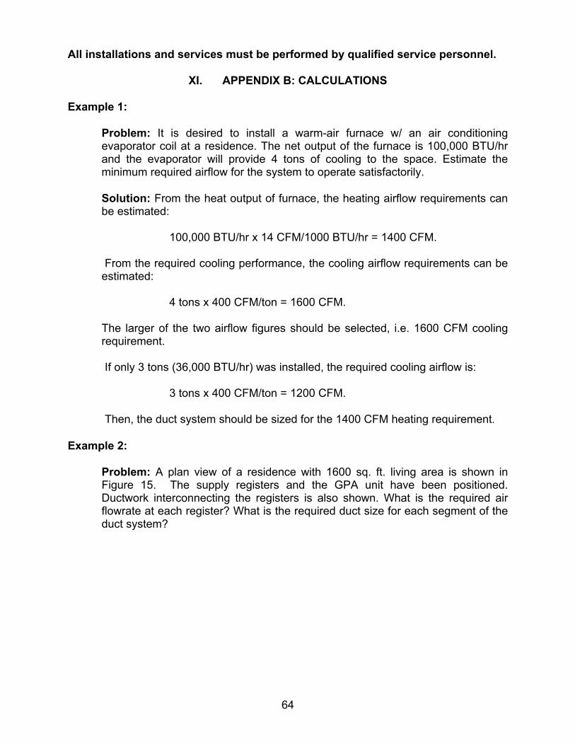
All installations and services must be performed by qualified service personnel.
64
XI. APPENDIX B: CALCULATIONS Example 1:
Problem: It is desired to install a warm-air furnace w/ an air conditioning evaporator coil at a residence. The net output of the furnace is 100,000 BTU/hr and the evaporator will provide 4 tons of cooling to the space. Estimate the minimum required airflow for the system to operate satisfactorily.
Solution: From the heat output of furnace, the heating airflow requirements can be estimated:
100,000 BTU/hr x 14 CFM/1000 BTU/hr = 1400 CFM.
From the required cooling performance, the cooling airflow requirements can be estimated:
4 tons x 400 CFM/ton = 1600 CFM.
The larger of the two airflow figures should be selected, i.e. 1600 CFM cooling requirement.
If only 3 tons (36,000 BTU/hr) was installed, the required cooling airflow is:
3 tons x 400 CFM/ton = 1200 CFM.
Then, the duct system should be sized for the 1400 CFM heating requirement.
Example 2:
Problem: A plan view of a residence with 1600 sq. ft. living area is shown in Figure 15. The supply registers and the GPA unit have been positioned. Ductwork interconnecting the registers is also shown. What is the required air flowrate at each register? What is the required duct size for each segment of the duct system?

All installations and services must be performed by qualified service personnel.
65
Figure 15: Plan View of a Typical Residence
Solution: If certain flowrates are desired, for heating or cooling reasons, or are required, by local codes, those guidelines should be followed. In lieu of other requirements, room floor area can be used to select flowrates for each room.
For instance, the floor area of the living room is 400-sq. ft. Using the result of our previous example, the required minimum air flowrate for the residence is 1400 CFM. The air flowrate for the living room will be the total flowrate multiplied by the ratio of the living room area to the total floor area or,
.350..1600
..400*1400 CFMftsqftsqCFMCFM RmLiving =⎟⎟
⎠
⎞⎜⎜⎝
⎛=
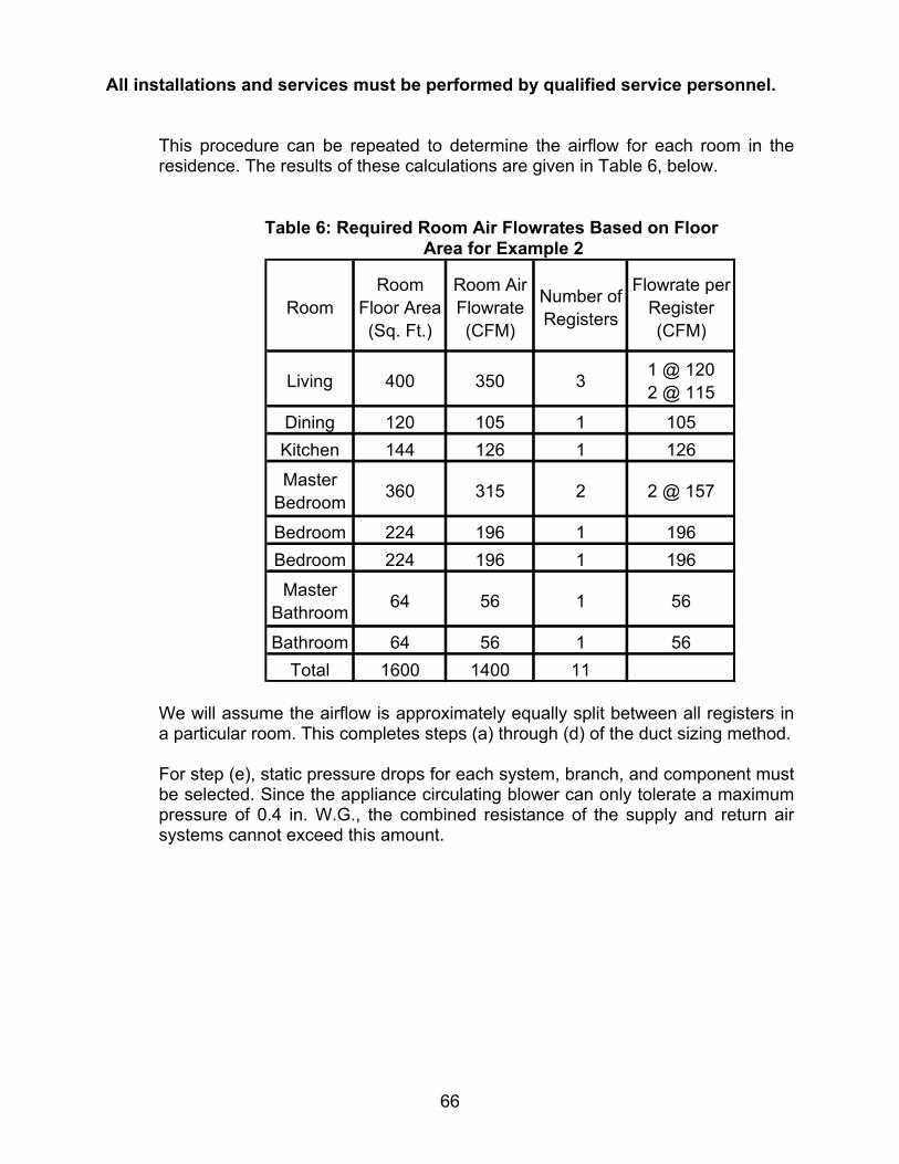
All installations and services must be performed by qualified service personnel.
66
This procedure can be repeated to determine the airflow for each room in the residence. The results of these calculations are given in Table 6, below.
Table 6: Required Room Air Flowrates Based on Floor
Area for Example 2
We will assume the airflow is approximately equally split between all registers in a particular room. This completes steps (a) through (d) of the duct sizing method.
For step (e), static pressure drops for each system, branch, and component must be selected. Since the appliance circulating blower can only tolerate a maximum pressure of 0.4 in. W.G., the combined resistance of the supply and return air systems cannot exceed this amount.
RoomRoom
Floor Area (Sq. Ft.)
Room Air Flowrate (CFM)
Number of Registers
Flowrate per Register (CFM)
Living 400 350 3 1 @ 120 2 @ 115
Dining 120 105 1 105Kitchen 144 126 1 126
Master Bedroom 360 315 2 2 @ 157
Bedroom 224 196 1 196Bedroom 224 196 1 196
Master Bathroom 64 56 1 56
Bathroom 64 56 1 56Total 1600 1400 11

All installations and services must be performed by qualified service personnel.
67
Therefore, choose a supply system static pressure drop of 0.2 in. W.G. (Then, the return air system will also have a static pressure drop of 0.2 in. W.G.) Furthermore, we will assume that the static pressure drops for all registers in the supply system will be 0.1 in. W.G. This leaves a static pressure drop of only 0.1 in. W.G. for all the ducting between the outlet flange of the appliance to each of the registers. (We will assume that the pressure drop through any short piece of ductwork connecting a branch to a register is included in the 0.1 in. W.G. pressure drop of the register.) Now, the size of the ducting for each segment of the duct system can begin.
For the branch of the duct system, which includes segments “A”, “B”, “C”, “F”, and “H”, the pressure drop cannot exceed 0.1 in. W.G. This branch of the duct system has two 90-degree turns. The total length of this branch is the sum of the lengths of each segment,
( ).71
.3.12.22.6.11.6.11ft
ftftftftftftftLLLLLLe HFCBAAH
=++++++=
++++=
Using the flowrate, total length of the duct, and the pressure drop, the required size of the duct can be determined using the following equation.
( ) ( )( )
2058.082.1
...)(*.*00123174.0. ⎥
⎦
⎤⎢⎣
⎡∆
=GWinP
CFMVftLeinD
**See page 75 for a copy of the ASHRAE chart. This equation is applicable to standard air between 50 to 90 degrees F flowing through clean, round, galvanized ductwork with approximately 40 joints per 100 feet. Using duct lengths in feet, flowrate in CFM, and pressure drop in inches W.G., the equation will calculate the required circular duct diameter in inches. (If it is desired to substitute rectangular duct for circular duct, refer to Table 7 for equivalent sizes.)
Returning to the example, for a total length of 71 ft., a flowrate of 120 CFM (from the farthest register on segment “A”), and a pressure drop of 0.1 in. W.G., the required duct diameter is,
.6.85.51.0
120*71*00123174.02058.082.1
ininD ≅=⎥⎦
⎤⎢⎣
⎡=

All installations and services must be performed by qualified service personnel.
68
However, there are two, 90 degree turns in the branch that will cause a large pressure drop, not accounted for in our calculations. To compensate for this drop, we should increase the effective length of the branch. For a 90 degree, mitered elbow, the equivalent straight duct length is given by the following formula,
( ) ( ) .12
.*65.90inDftL elbow =
For a 6-inch diameter 90-degree elbow, the equivalent straight duct length is,
.5.32126*6590 ftL elbow ==
So, the total equivalent straight duct length is,
..136.5.32*2.71 ftftftLe =+=
Now, the required duct diameter should be recalculated,
.7.67.61.0
120*136*00123174.02058.082.1
ininDA ≅=⎥⎦
⎤⎢⎣
⎡=
Thus, for section ”A”, the required duct diameter is 7 inches.
Now, it is necessary to determine the allowable pressure drops for all other segments in the branch. The equation for duct diameter can be rearranged to give the pressure drop for any flowrate, providing the duct length, the flowrate, and the duct diameter are known. The equation looks like this,
( ) ( ) ( )( )
..
*.*00123174.0... 86.4
82.1
inDCFMVftLeGWinP =∆
For section “B”, if the flowrate is 120 CFM, the length is 11 ft., and the duct diameter 7-in., the pressure drop will be,
....00644.07
120*11*00123174.086.4
82.1
GWinPB ==∆
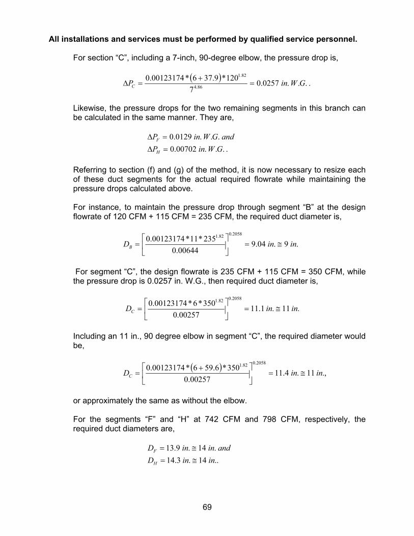
All installations and services must be performed by qualified service personnel.
69
For section “C”, including a 7-inch, 90-degree elbow, the pressure drop is,
( ) ....0257.07
120*9.376*00123174.086.4
82.1
GWinPC =+
=∆
Likewise, the pressure drops for the two remaining segments in this branch can be calculated in the same manner. They are,
....00702.0...0129.0GWinPandGWinP
H
F
=∆=∆
Referring to section (f) and (g) of the method, it is now necessary to resize each of these duct segments for the actual required flowrate while maintaining the pressure drops calculated above.
For instance, to maintain the pressure drop through segment “B” at the design flowrate of 120 CFM + 115 CFM = 235 CFM, the required duct diameter is,
.9.04.900644.0
235*11*00123174.02058.082.1
ininDB ≅=⎥⎦
⎤⎢⎣
⎡=
For segment “C”, the design flowrate is 235 CFM + 115 CFM = 350 CFM, while the pressure drop is 0.0257 in. W.G., then required duct diameter is,
.11.1.1100257.0
350*6*00123174.02058.082.1
ininDC ≅=⎥⎦
⎤⎢⎣
⎡=
Including an 11 in., 90 degree elbow in segment “C”, the required diameter would be,
( ) .,11.4.1100257.0
350*6.596*00123174.02058.082.1
ininDC ≅=⎥⎦
⎤⎢⎣
⎡ +=
or approximately the same as without the elbow.
For the segments “F” and “H” at 742 CFM and 798 CFM, respectively, the required duct diameters are,
..14.3.14
.14.9.13ininDandininD
H
F
≅=≅=

All installations and services must be performed by qualified service personnel.
70
Next, the branch of the system, which includes segments “D” and “E” can be evaluated. To balance the system, the pressure drop for segments “D” and “E” combined must be approximately equal to the pressure drops of segments “A”, “B” and “C” combined. Thus,
.CBADE PPPPP ∆+∆+∆=∆+∆
Using the previous pressure drop equation, the pressure drop through segment “A” is 0.0321 in. W.G. Then, the pressure drop for the “D” and “E” branch is,
....0643.0...0257.0...0644.0...0321.0
GWinGWinGWinGWinPP DE
=++=∆+∆
The duct diameter required to pass 196 CFM @ 0.0643 in. W.G. pressure drop is,
( ) .,6.73.5
0643.0196*17*00123174.0
2058.082.1
ininDE ≅=⎥⎦
⎤⎢⎣
⎡=
Including a 6 in., 90-degree elbow in segment “E”, the required diameter would be,
( ) .,7.14.70643.0
196*5.3217*00123174.02058.082.1
ininDE ≅=⎥⎦
⎤⎢⎣
⎡ +=
or approximately 1 inch larger than without the elbow. The pressure drop through segment “D” should be calculated for a 5-ft. straight section with a 7-in., 90-degree elbow. From our previous equation, the pressure drop is about,
( ) ....0614.07
196*9.375*00123174.086.4
82.1
GWinPD =+
=∆
The flowrate through section “D” is 392 CFM (196 CFM + 196 CFM). With the required pressure drop, the duct diameter is,
( ) ..9.07.90614.0
392*9.375*00123174.02058.082.1
ininDD ≅=⎥⎦
⎤⎢⎣
⎡ +=
Recalculating the duct size considering the effective length of a 9 in., 90 degree elbow,

All installations and services must be performed by qualified service personnel.
71
( ) ,.10.50.90614.0
392*75.485*00123174.02058.082.1
ininDD ≅=⎥⎦
⎤⎢⎣
⎡ +=
or an increase in duct size of about 1 inch in diameter.
The pressure drops for the remaining branches of the system must be set. This includes segment “G”; segments “I” and “J”; and segments “K”, “L”, and “M”. To balance the system, the pressure drop for each branch must be approximately equal to the pressure drops of the other branches. For example, segment “G” must equal segments “D”, “E” and “F” combined. Thus,
.FEDG PPPP ∆+∆+∆=∆
Likewise for the other branches,
....1.0...1.0
GWinPPPGWinPP
mlK
JI
=∆+∆+∆=∆+∆
Using the previous technique, duct sizes can be found for all the remaining segments. The duct sizes adequate for the entire supply system are summarized in Table 7, below.
Table 7: Required Duct Sizes for the Residence in Example 2
Duct Segment
Air Flowrate (CFM)
Circular Duct Dia.
(in.)
Air Velocity in Circular Duct
(FPM)
Equivalent Rectangular Duct Dim.s
(in.)
A 120 7 449 6 x 6B 235 9 532 8 x 8C 350 11 530 10 x 10D 392 10 719 9 x 9E 196 7 733 6 x 6F 742 14 694 13 x 13G 56 3 1141 N/AH 798 14 746 13 x 13I 126 5 924 N/AJ 231 7 864 6 x 6K 370 10 678 9 x 9L 304 9 688 8 x 8M 157 7 587 6 x 6
N/A - Not Applicable

All installations and services must be performed by qualified service personnel.
72
Example 3:
Problem: Refrigerant measurements are made on the cooling system of a typical GPA installation. The suction line pressure, measured at the condenser unit, suction line, charging port, is 68 PSIG. The temperature of the refrigerant (R22) at the evaporator suction line connection is measured as 48°F. What is the degree of superheat for this system?
Solution: Calculate the pressure of the refrigerant at the evaporator suction line connection. With the estimated refrigerant pressure and measured temperature at the same point, tabulated data on R22 from the refrigerant manufacturer, or ASHRAE, can be used to evaluate the degree of superheat.
68 PSIG (Suction pressure measured at condenser) + 0 PSIG (Added for pressure drop of suction line) ------------------ 68 PSIG = Estimated pressure of refrigerant at evaporator exit
From the R22 pressure/temperature chart, Figure 16, at 68 PSIG (82.7 PSIA), the saturation temperature is approximately 40°F
Figure 16: Saturation Temperature vs. Pressure for Refrigerant 22 (R22)
0
20
40
60
80
100
120
140
160
0.0 50.0 100.0 150.0 200.0 250.0 300.0 350.0
Pressure (PSIG)
Tem
pera
ture
(deg
. F.)

All installations and services must be performed by qualified service personnel.
73
Now, the degree of superheat can be calculated. 48°F (Suction line temperature at outlet of evaporator)
- 40°F (Saturation temperature for R22 at 68 PSIG) ----------------------- 8°F = Degree of evaporator superheat.
Example 4:
Problem: Additional refrigerant measurements are made on the cooling system of our typical GPA installation. The liquid line pressure, measured at the condenser unit, liquid line, charging port, is 210 PSIG. The temperature of the refrigerant (R22) at the evaporator liquid line connection is measured as 95°F. What is the degree of subcooling for this system?
Solution: Calculate the pressure of the refrigerant at the evaporator liquid line connection. With the estimated refrigerant pressure and measured temperature at the same point, tabulated data on R22 from the refrigerant manufacturer, or ASHRAE, can be used to evaluate the degree of subcooling.
210 PSIG (Liquid line pressure measured at condenser) + 0 PSIG (Added for pressure drop of liquid line) ------------------ 210 PSIG = Estimated pressure of refrigerant at evaporator inlet
From the R22 pressure/temperature chart, at 210 PSIG (224.7 PSIA), the saturation temperature is approximately 105°F
Now, the degree of subcooling can be calculated.
105°F (Saturation temperature for R22 at 210 PSIG)
- 95°F (Suction line temperature at outlet of evaporator) ------------------ 10°F = Degree of evaporator subcooling

All installations and services must be performed by qualified service personnel.
74

All installations and services must be performed by qualified service personnel.
75
XII. APPENDIX C: ELECTRICAL SCHEMATIC AND CONNECTION DIAGRAM
W
AR
NIN
G
OP
EN
DIS
CO
NN
EC
TS
WIT
CH
BE
FOR
ES
ER
VIC
ING
BE
SU
RE
UN
IT
IS G
RO
UN
DE
D

All installations and services must be performed by qualified service personnel.
76
XIII. APPENDIX D: SEQUENCE OF OPERATIONS
A. SEQUENCE OF OPERATIONS FOR THE HEATING SYSTEM
Mode of Operation
Start
Start trial for ignition
Standby(At any time the oil
valve is not energized)
On power interruption, systemshuts off, restarts when
power is restored.
Ignition electrodes spark.Burner motor energized.
Thermostat calls for heat,contacts close
Control System Action
Oil valve energized after15 second time delay.
Flame must be detectedafter 45 seconds.
OPA 1 of 2
The retry sequence provides a60 second wait before ignition
is attempted again.
If flame is not detected, theoil valve is de-energized,
the ignitor is turned off and the ignition control module
goes into the "retry" sequence.
Continous safe operation check. Ifflame simulation condition present,system shuts off oil valve,ignitor,and burner motor; activates fast
flashing LED.

All installations and services must be performed by qualified service personnel.
77
Control System Action
Main Burner Operation
Mode of Operation
Call for HeatSatisfied
End of Cycle
System Lockout
After 45 second delay, theignition electrodes are de-energized. The circulating
air fan is energized at heatingspeed. The (optional) electronic
air cleaner & humidifier are energized.
If ignition attempt is unsuccessful,the ignition control module goes into
system lockout.
When thermostat is satisfied,contacts open and the oil
valve is de-energized. Aftera 2 minute burner off delay,
burner motor is de-energized.The 2 minute delay- to- fan-off
period begins.
After the delay-to-fan-offperiod ends, the circulating
air fan and {optional) electronic air cleaner are
de-energized.
OPA 2 of 2
Repeat IgnitionTrial
If system is in lockout,(check if LEDis flashing fast) try to recycle the
system by depressing the RESET button on the ignition control module.
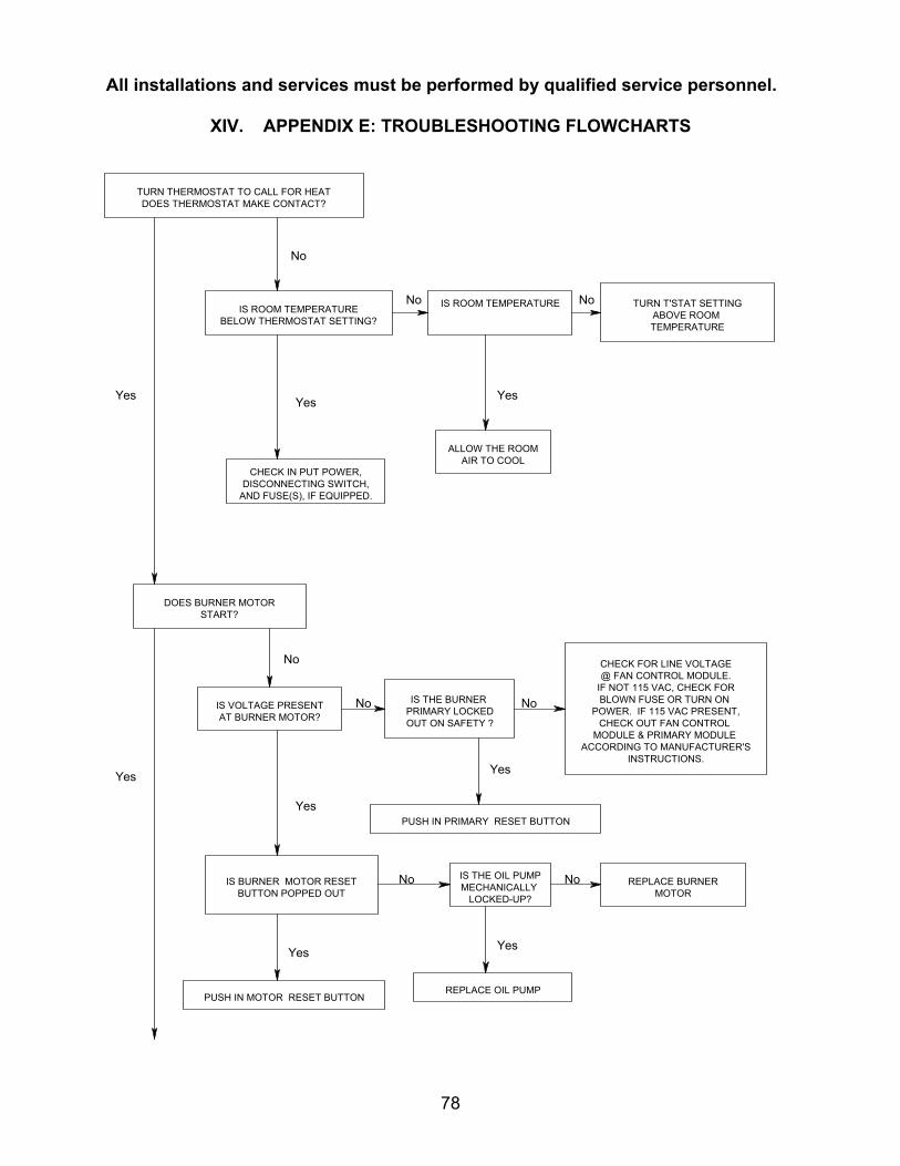
All installations and services must be performed by qualified service personnel.
78
XIV. APPENDIX E: TROUBLESHOOTING FLOWCHARTS
TURN THERMOSTAT TO CALL FOR HEATDOES THERMOSTAT MAKE CONTACT?
REPLACE BURNERMOTOR
IS ROOM TEMPERATUREBELOW THERMOSTAT SETTING?
IS THE OIL PUMPMECHANICALLY
LOCKED-UP?
TURN T'STAT SETTINGABOVE ROOM TEMPERATURE
IS ROOM TEMPERATURENo No
REPLACE OIL PUMP
Yes
Yes
ALLOW THE ROOMAIR TO COOL
No
IS VOLTAGE PRESENTAT BURNER MOTOR?
No
Yes
Yes
Yes
IS THE BURNER PRIMARY LOCKEDOUT ON SAFETY ?
NoNo
Yes
No
CHECK FOR LINE VOLTAGE@ FAN CONTROL MODULE.
IF NOT 115 VAC, CHECK FORBLOWN FUSE OR TURN ON
POWER. IF 115 VAC PRESENT,CHECK OUT FAN CONTROL
MODULE & PRIMARY MODULE ACCORDING TO MANUFACTURER'S
INSTRUCTIONS.
PUSH IN PRIMARY RESET BUTTON
IS BURNER MOTOR RESETBUTTON POPPED OUT
DOES BURNER MOTORSTART?
PUSH IN MOTOR RESET BUTTON
CHECK IN PUT POWER,DISCONNECTING SWITCH,
AND FUSE(S), IF EQUIPPED.
No
Yes
Yes

All installations and services must be performed by qualified service personnel.
79
BLOWER RUNSNORMAL CYCLE?
IS IGNITION ESTABLISHED?
FURNACE OPERATES FOR COMPLETE CYCLE?
BURNER RUN NORMALCYCLE?
IS HEAT ANTICAPATOR SETTO MILLIAMP SETTING
MEASURED ON SUBBASE?
Yes
Yes
Yes
Yes
Yes
No
No
CHECK-BLOWER SPEEDAND RETURN AIR TEMPERATURE
No MEASURE MILLIAMPS BETWEEN 'W' &'R'ON THE T'STAT SUBBASE AND SET HEAT
ANTICIPATOR ACCORDINGLY
IS THE OIL PUMPOPERATING?
No IS THE COUPLING BETWEENTHE BURNER MOTOR AND
THE PUMP STRIPPED?
No
YesREPLACE COUPLER
REPLACE PUMP
IF PROBLEM PERSISTS CONTINUE TO NEXT SECTION.
ARE THE ELECTRODESARCING?
Yes
No
IS IGNITION TRANSFORMERCAPABLE OF PRODUCING A
3/4" ARC? (10,000 VAC)
REPLACE IGNITIONTRANSFORMER
No
Yes
Yes
No IS TEMPERATURE RISE No
CHECK FAN ON & OFF (DIP SWITCH)SETTINGS ON FAN CONTROL
Yes
IS OIL AVAILABLE TO THE BURNER?No
No
DETERMINE IF THE ELECTRODES AREALIGNED, CONTACT SPRINGS TOUCHING
ELECTRODE RODS, & PORCELAININSULATORS CLEAN AND
UNCRACKED. ADJUST OR REPLACE,AS NECESSARY.
VERIFY ALL OIL VALVE(S) ARE OPEN,OIL TANK IS SUFFICIENTLY FULL,
AND OIL LINE CONTAINS OIL.

All installations and services must be performed by qualified service personnel.
80
PROPER COMBUSTION ACHIEVED?
No
No
No
IS PUMP PRESSURE SETACCORDING TO BURNER
APPLICATION CHART
IS THE NOZZLEPLUGGING?
No IS BURNER SET TOPRODUCE A TRACE
OF SMOKE ANDTHEN "DETUNED".
IS WATER, DIRT, ORSLUDGE PRESENT IN
THE OIL SYSTEM?
NoIS COMBUSTION AIR
Yes
TRY TO RAISE ROOM & OIL
IF THIS CANNOT BE DONE DOTHE FOLLOWING:
DECREASE NOZZLE SIZE ANDINCREASE PUMP PRESSURE.CHOOSE SMALLER NOZZLESIZE AND PUMP PRESSURE
FROM "EFFECTS OF PRESSUREON NOZZLE FLOW RATES" ATTHE END OF THE TROUBLE
SHOOTING SECTION.
IS THE PROBLEM DELAYEDIGNITION?
ARE THE ELECTRODESPROPERLY ALIGNED?
Yes
Yes
Yes
Yes
ADJUST TO 100-120 PSIUNLESS COMBUSTIONAIR OR OIL BELOW 50
deg. F IS PRESENT (THISIS CONSIDERED BELOW)
ADJUST AIR TO A TRACE OFSMOKE, THEN TAKE CO2 OR
O2 READING, NEXT SUBTRACT1% FROM THE CO2 OR ADD 1%TO O2 . THEN, ADJUST AIR TO
OBTAIN NEW CO2 OR O2 VALUES.
REPAIR OR REPLACE TANKTO PREVENT FUTURE
PROBLEMS. MIXIN PROPER ADDITIVES
TO REMOVE WATERAND SLUDGE
Yes
Yes
No
CORRECT INSERTION ORAIR TUBE BURNOFF
MAY OCCUR.
NoIS THE AIR TUBE INSERTION0-1/4" BACK FROM INSIDE
OF REFRACTORY?
Yes
No
ALIGN ELECTRODES PERBURNER INSTRUCTION
MANUAL SPECIFICATIONS
ARE VENT TERMINAL AND HEATEXCHANGER CLEAN?

All installations and services must be performed by qualified service personnel.
81
IS THE TEMPERATUREDIFFERENCE BETWEEN SUPPLY
IS STACK TEMPERATURE
DOES FURNACE OPERATEWITHOUT CONDENSING?
TROUBLE SHOOTING ENDS.
REPEAT PROCEDURE UNTIL TROUBLE FREE OPERATION IS OBTAINED.
Yes
Yes
Yes
Yes
No
No
No
No
Yes
EFFECTS OF PRESSURE ON NOZZLE FLOW RATE
NOZZLERATING
AT100 PSI
NOZZLE FLOW RATES INGALLONS PER HOUR (Approx.)
80 PSI 120 PSI 140 PSI
NOZZLE FLOW RATES IN GALLONS PER HOUR (Approx.)
80PSI 120PSI 140PSI
NOZZLERATING
AT100 PSI
0.450.580.670.760.810.890.991.071.12
0.550.710.820.930.991.101.211.311.37
0.590.770.891.001.071.181.301.411.48
1.351.501.651.752.002.252.502.753.00
1.211.341.481.571.792.012.212.442.69
1.481.641.811.922.192.472.743.003.29
1.601.781.952.072.372.662.963.243.55
.50
.65
.75
.85
.901.001.101.201.25
IS BURNER SET AS INDICATEDIN ABOVE SECTION?
ADJUST BURNER COMBUSTIONTO PRODUCE ZERO SMOKE.
SLOW THE BLOWER SPEEDTO RAISE TEMPERATURE
RISE.
INCREASE LENGTH OF BURNER ON CYCLEBY RESETTING BURNER PRIMARY CONTROLDIP SWITCHES FOR A LONGER OFF DELAY.
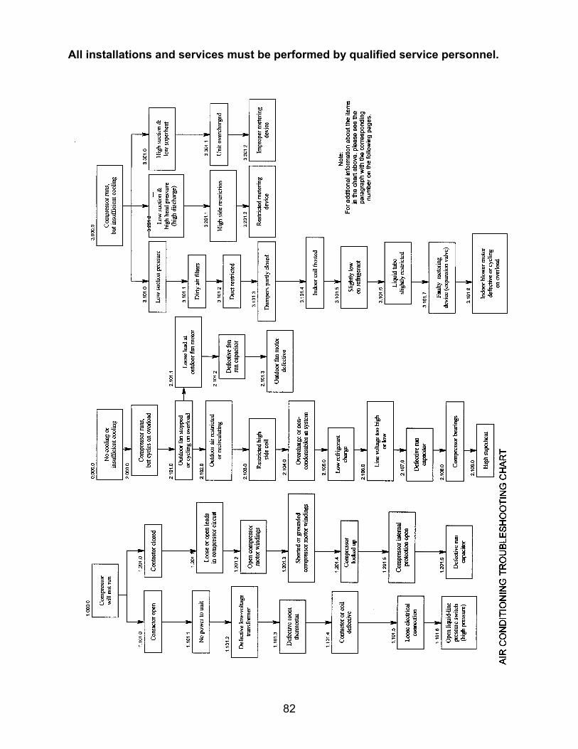
All installations and services must be performed by qualified service personnel.
82
All installations and services must be performed by qualified service personnel.
83
Notes for Air Conditioning Troubleshooting Guide 1.101.0 Check to see if the contactor has not pulled in. If the coil has not pulled in the
contactor, check for 24 VAC to the coil on the contactor. 1.101.1 Check to make sure the control transformer is powering the 115 VAC circuit. 1.101.2 Check for 115 VAC to the control transformer. Check control fuse for 115 VAC
supply. 1.101.3 Check to see if the thermostat is closing to complete the 24 VAC circuit.
Remove thermostat and jump terminals R-Y and R-G. If jumping the sub-base works, replace thermostat.
1.101.4 If the contactor is reading 24 VAC on the coil, but is not pulling in the contactor,
replace the contactor. 1.101.5 Check the entire 24 VAC circuit between the thermostat, fan control, and
contactor for loose connections and wires pulled away from terminations or terminals. These conditions can cause an open circuit.
1.101.6 Check for 24 VAC across the refrigerant high-pressure switch. If 24 VAC is
present, reset the red button on the switch and recheck for 24 VAC. 1.201.0 If the contactor is closed and line voltage is measured across lines L1 and L2
but the unit does not run, proceed with the following checks. 1.201.1 Check 240-volt wire leads to the capacitors and the compressor. Make sure
the terminals on the compressor and capacitors are not touching or loose. 1.201.2 Check for continuity across the three terminals of the compressor. (If
continuity is not measured, the compressor windings are opened.) 1.201.3 Check for grounded compressor windings by checking continuity to ground. 1.201.4 The compressor may be tapped with a rubber mallet, or piece of wood, to jar
the compressor loose. 1.201.5 Allow the compressor to cool below 130°F. Check for continuity between
terminals S and C on the compressor. If you do not have continuity, the thermal protector may require more time to cool down.
1.201.6 Check capacitance of the run capacitor.
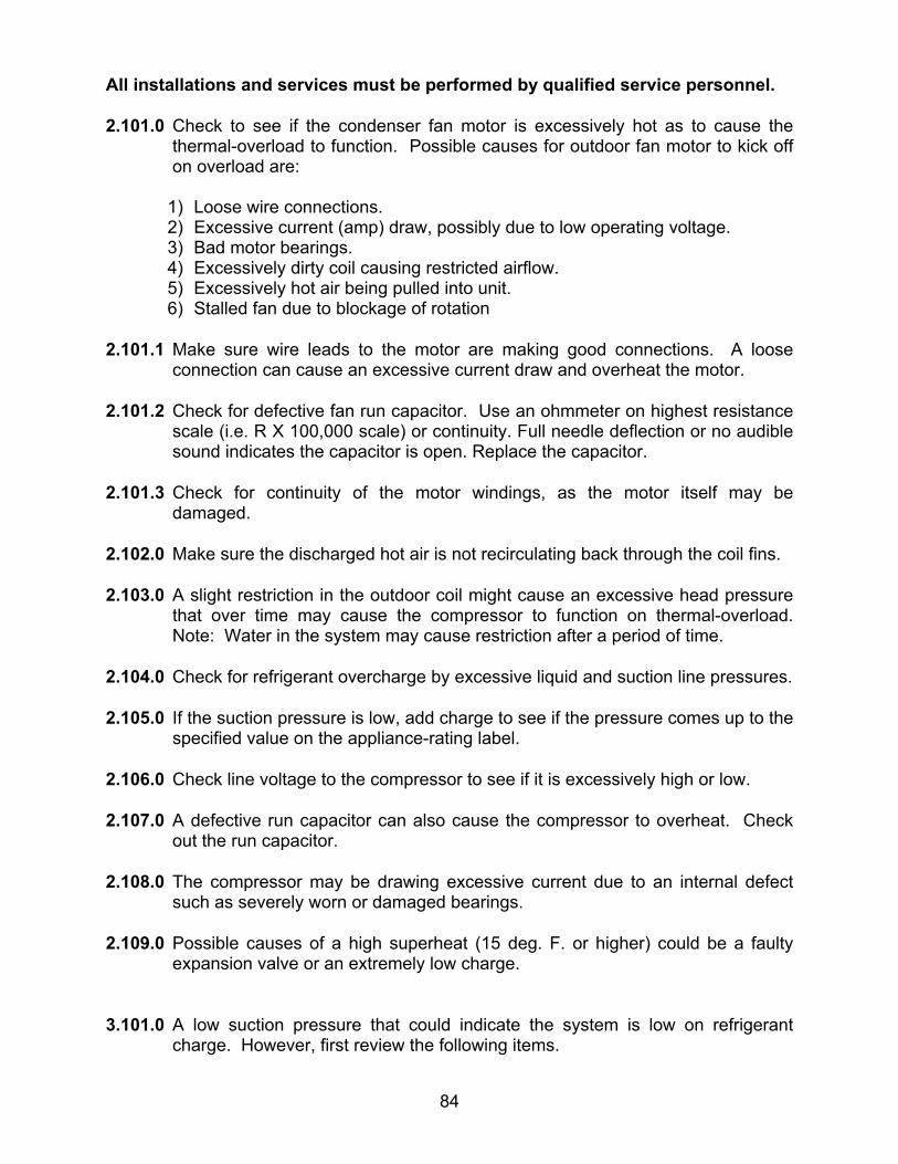
All installations and services must be performed by qualified service personnel.
84
2.101.0 Check to see if the condenser fan motor is excessively hot as to cause the thermal-overload to function. Possible causes for outdoor fan motor to kick off on overload are:
1) Loose wire connections. 2) Excessive current (amp) draw, possibly due to low operating voltage. 3) Bad motor bearings. 4) Excessively dirty coil causing restricted airflow. 5) Excessively hot air being pulled into unit. 6) Stalled fan due to blockage of rotation
2.101.1 Make sure wire leads to the motor are making good connections. A loose connection can cause an excessive current draw and overheat the motor.
2.101.2 Check for defective fan run capacitor. Use an ohmmeter on highest resistance
scale (i.e. R X 100,000 scale) or continuity. Full needle deflection or no audible sound indicates the capacitor is open. Replace the capacitor.
2.101.3 Check for continuity of the motor windings, as the motor itself may be
damaged. 2.102.0 Make sure the discharged hot air is not recirculating back through the coil fins. 2.103.0 A slight restriction in the outdoor coil might cause an excessive head pressure
that over time may cause the compressor to function on thermal-overload. Note: Water in the system may cause restriction after a period of time.
2.104.0 Check for refrigerant overcharge by excessive liquid and suction line pressures. 2.105.0 If the suction pressure is low, add charge to see if the pressure comes up to the
specified value on the appliance-rating label. 2.106.0 Check line voltage to the compressor to see if it is excessively high or low. 2.107.0 A defective run capacitor can also cause the compressor to overheat. Check
out the run capacitor.
2.108.0 The compressor may be drawing excessive current due to an internal defect such as severely worn or damaged bearings.
2.109.0 Possible causes of a high superheat (15 deg. F. or higher) could be a faulty
expansion valve or an extremely low charge. 3.101.0 A low suction pressure that could indicate the system is low on refrigerant
charge. However, first review the following items.

All installations and services must be performed by qualified service personnel.
85
3.101.1 Dirty air filters may restrict the airflow across the evaporator coil resulting in
frost on the coil. 3.101.2 Are the duct system and air blower setup to move enough air to have an 18-20
degree F. drop across the coil? 3.101.3 Are there any registers or dampers closed restricting the airflow of the duct
system? 3.101.4 If the evaporator coil frosts, this indicates a low charge or insufficient air
movement. 3.101.5 The coil may not frost up, but still not cool properly. Is the system slightly low
on refrigerant? Check for an 18°F temperature drop across the coil.
3.101.6 Make sure the liquid line has not kinked or collapsed slightly causing a restriction.
3.101.7 Hold bulb in hand to see if the pressure changes (this action should increase
the suction pressure). 3.101.8 Check out the supply/return air blower to make sure it is functioning properly
and not shutting down on thermal-overload, due to high motor temperatures. 3.201.0 Check the following items for high suction pressure and low liquid pressure.
Allow at least 5 minutes off time for valve to close when pressures have equalized if compressor has internal pressure relief valve.
3.201.1 There may be a restriction in the condenser coil. This could be caused by water or other contaminants in the system. A restriction in the coil is a very rare problem.
3.201.2 Check the expansion valve for restriction of the metering orifice. 3.301.0 For high suction pressure and low superheat temperatures, review the following
items. 3.301.1 If the system is overcharged with refrigerant, the system will become flooded.
Consequently, the evaporator coil will not effectively absorb heat from the airflow. The temperature drop across the evaporator coil will be low.
3.301.2 Check for a properly sized expansion valve.
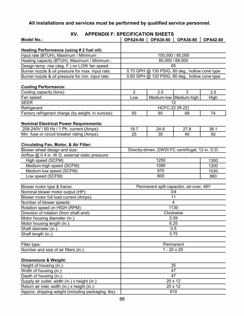
All installations and services must be performed by qualified service personnel.
86
XV. APPENDIX F: SPECIFICATION SHEETSModel No.: OPA24-80 OPA30-80 OPA36-80 OPA42-80
Heating Performance (using # 2 fuel oil):Input rate (BTUH), Maximum / Minimum :Heating capacity (BTUH), Maximum / Minimum : Design temp. rise (deg. F.) on LOW fan speed:Burner nozzle & oil pressure for max. input rate:Burner nozzle & oil pressure for min. input rate:
Cooling Performance:Cooling capacity (tons): 2 2.5 3 3.5Fan speed: Low Medium-low Medium-high HighSEERRefrigerant: Factory refrigerant charge (by weight, in ounces): 65 65 68 74
Nominal Electrical Power Requirements: 208-240V / 60 Hz / 1 Ph. current (Amps): 18.7 24.9 27.8 36.1Min. fuse or circuit breaker rating (Amps): 25 35 40 50
Circulating Fan, Motor, & Air Filter:Blower wheel design and size:Airflow @ 0.4 in. W.G. external static pressure: High speed (SCFM): 1300 Medium-high speed (SCFM): 1200 Medium-low speed (SCFM): 1030 Low speed (SCFM): 860
Blower motor type & frame:Nominal blower motor output (HP):Blower motor full load current (Amps):Number of blower speeds:Rotation speed on HIGH (RPM): Direction of rotation (from shaft end):Motor housing diameter (in.):Motor housing length (in.):Shaft diameter (in.):Shaft length (in.):
Filter type:Number and size of air filters (in.):
Dimensions & Weight:Height of housing (in.):Width of housing (in.):Depth of housing (in.):Supply air outlet, width (in.) x height (in.):Return air inlet, width (in.) x height (in.):Approx. shipping weight (including packaging, lbs):
20 x 12610
20 x 1247
3547
Permanent1 - 20 x 25
5.596.250.53.75
114
1130Clockwise
Directly-driven, DWDI FC centrifugal, 12 in. O.D.
Permanent split capacitor, air-over, 48Y3/4
12501090970800
0.60 GPH @ 120 PSIG, 80 deg., hollow cone type
12HCFC-22 (R-22)
105,000 / 85,00085,000 / 68,000
650.75 GPH @ 130 PSIG, 80 deg., hollow cone type

All installations and services must be performed by qualified service personnel.
87
APPENDIX G: REPLACEMENT PARTS LIST

All installations and services must be performed by qualified service personnel.
88

All installations and services must be performed by qualified service personnel.
89
XVI. APPENDIX H: OPA HEATING AND COOLING SYSTEMS TEST FORM
Name:Address:City, State, & Zip Code:Model No.:Serial No.:Burner Model No.:Mfgr & Model of Fuel Oil Filter:Combustion Tests * Service # 1 Service # 2 Service # 3Combustion Chamber Condition:Nozzle Size & Type:Oil Pump Pressure (PSIG):CO2 (%):O2 (%):Smoke No.:Approximate Air Shutter Opening
(% of max.):Gross Flue Gas Temp. (deg. F):Ambient Air Temp. (deg. F):Net Flue Gas Temp. (deg. F):Thermal Efficiency (%):
Is Control Operation OK?Any Oil Leaks?Refrigeration Tests * Service # 1 Service # 2 Service # 3Suction Line Pressure (PSIG):Suction Line Temp. (deg. F.):Sat. Temp. @ Evap.(deg. F.):Evaporator Superheat (deg. F.):Liquid Line Pressure (PSIG):Sat. Temp. @ Cond.(deg. F.):Liquid Line Temp. (deg. F.):Condenser Subcooling (deg. F.):
Is Control Operation OK?Any Refrigerant Leaks? Tests Performed By:Date:Notes:
Name:Address:Phone No:
* Operate system for at least 10 minutes before taking measurements.
Customer
Appliance
Complete this form for each Thermo Pride OPA appliance installed. Read the instruction manual carefully before making tests. Retain this form with appliance.
Technician
Installer
AFG-TP1501
Initial Installation
Initial Installation
Heating System
Cooling System


