Outdoor Circuit Breaker for Railway Technical...
17
Medium Voltage Distribution CBR Outdoor Circuit Breaker for Railway Technical description December 2011
Transcript of Outdoor Circuit Breaker for Railway Technical...
Medium Voltage Distribution
CBR Outdoor Circuit Breaker for Railway Technical description December 2011
CBR technical description in Eng 12-2011.doc Page 2 / 17
1 General presentation CBR is an outdoor pole mounted single-phase circuit breaker for railway applications, based on the combination of vacuum switching together with low-pressure gas insulation technology. CBR is available in one-pole or two-pole versions. The two-pole version is for the double supply system catenary + feeder. All pole components are mounted inside a fully welded stainless steel tank providing a sealed-for-life gasket free enclosure. No maintenance is required. Remotely controlled, CBR has also a mechanical and manual opening command for emergency or security purposes. A position indicator clearly visible from the ground gives a reliable status of the contact. CBR has been designed and tested to meet or exceed the requirements of all relevant standards:
IEC 62271-100, 60376, 60529, , 60694, 60815 CENELEC EN 50124, 50125, 50152-1, 50163, 60529, 60721-3&4
CBR is manufactured in Schneider Electric’s ISO 9001, 14001 and OHSAS 18001 certified workshops
2 Scope of supply
Item Description
1 One-pole outdoor circuit breaker for railway network : 27.5kV-50Hz– breaking capacity: 25kA, rated current: 2000A, type CBR 25-25-20 / V1 with a control cabinet
2 Two-pole outdoor circuit breaker for railway network : 27.5kV-50Hz– breaking capacity: 25kA, rated current: 2000A, type CBR 25-25-20 / V2 with a control cabinet

3 Description CBR has been developed jointly with leading Railway Companies, to achieve reliability and security for the feeders or catenaries supply. CBR is available in single pole or two pole versions. A two-pole version has two identical poles to operate in synchronization (for example feeder and catenary autotransformer). Equipment is made up of: • One or two poles according the selected version • Support frames for sub station or catenary pole • A control cabinet Installation
Two-pole version One pole on substation structure
CBR technical description in Eng 12-2011.doc Page 3 / 17

Electrical pole Sealed-for-life tank The vacuum switch is mounted in a fully welded anti-corrosion stainless steel tank providing a sealed-for-life gasket free enclosure. Insulation gas is SF6 at low pressure (0.5 bar relative). The low level of gas leakage gives a lifetime over 30 years. For safety of personnel, a pressure relief device is welded on the tank in the event of internal arc fault. Pressure sensor CBR is equipped with a SF6 pressure monitoring device. The low pressure level (0.3bar) is signalled through contacts normally closed when pressure is correct. This information is transferred to the Central Control Centre. Vacuum interrupter Load interruption is achieved using the latest generation of Schneider Electric vacuum interrupters: axial magnetic field arc control for better performance. Actuator Operation is by a magnetic actuator, an efficient bistable mechanism with permanent magnets installed in the sealed-for-life tank. This arrangement replaces the motor-operated spring type. Figure here below illustrates the operating sequences. In closed or open position, the field of the permanent magnet ensures two stable positions. For a command, a current discharge in a coil creates a high magnetic field to move the contact. The opening operation is guaranteed by an extra spring to ensure independent speed whatever the energy on the coil. OPEN position Closed command CLOSED Position Open Command No maintenance is required. Mechanical and electrical endurance is guaranteed to 10 000 operations. Flexible stainless steel bellows permits a manual opening operation of the circuit breaker without compromising the integrity of the welded tank structure. No mechanical closed command is available. Auxiliary contacts Auxiliary contacts are directly linked with the moving part of the vacuum bottle. Three pairs (3NO+3NC) of auxiliary contacts are available for customer purpose. Additional contacts through relays can be added in the control unit.
CBR technical description in Eng 12-2011.doc Page 4 / 17
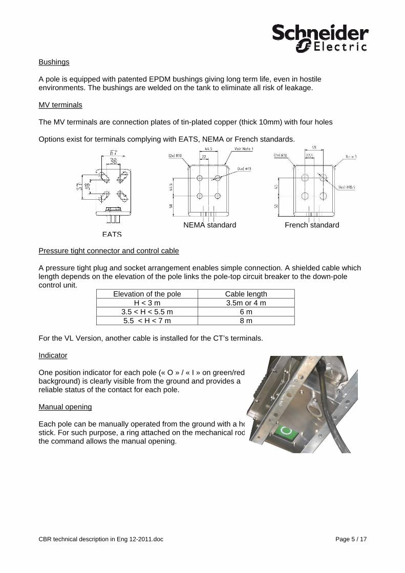
Bushings A pole is equipped with patented EPDM bushings giving long term life, even in hostile environments. The bushings are welded on the tank to eliminate all risk of leakage. MV terminals The MV terminals are connection plates of tin-plated copper (thick 10mm) with four holes Options exist for terminals complying with EATS, NEMA or French standards.
CBR technical description in Eng 12-2011.doc Page 5 / 17
NEMA standard French standard
EATS Pressure tight connector and control cable A pressure tight plug and socket arrangement enables simple connection. A shielded cable which length depends on the elevation of the pole links the pole-top circuit breaker to the down-pole control unit.
Elevation of the pole Cable length H < 3 m 3.5m or 4 m
3.5 < H < 5.5 m 6 m 5.5 < H < 7 m 8 m
For the VL Version, another cable is installed for the CT’s terminals. Indicator One position indicator for each pole (« O » / « I » on green/red background) is clearly visible from the ground and provides a reliable status of the contact for each pole. Manual opening Each pole can be manually operated from the ground with a hook stick. For such purpose, a ring attached on the mechanical rod of the command allows the manual opening.

VL version option In the VL version, one of the bushing is on the top of the product. This design reduces the overall width. It could facilitate the installation on gantry. A specific support frame exists in order to respect the clearance distance.
CBR technical description in Eng 12-2011.doc Page 6 / 17
On the vertical bushing, toroidal CT’s can be installed. CT’s outputs are connected in the LV cabinet. A dedicated plug is installed on the frame of the pole. Support structure For a substation installation, a dedicated support structure (2.5m height) allows the CBR installation above the structure for a one-pole version or at 1.5m distance for a two-pole version.
One pole substation structure Two-pole substation structure For a mounting on an existing catenary structure, brackets are designed to provide an efficient and secure mounting method.
Brackets for a two-pole model Brackets for CBR VL

Control cabinet Located at the bottom of the pole, the control cabinet monitors the following functions • Indication of Circuit Breaker position • Indication of capacitor charge (closing) • Operation counter • Control Interface • Local or remote operation The door can be locked by a padlock (Ø 10) Control interface The control of the Circuit Breaker can be achieved remotely from the CTCC (Central Traffic Control Centre).
1. Local / remote function A switch selects the function. In option, this switch can be locked by key in both positions or by padlock.
2. Opening operation: Remotely from the Central Traffic Control Centre: direct electric connection to the
opening coil. Tripping from the protection relay Locally from the push button (option) Manually pulling an accessible ring on the support with a hook stick. Automatically in case of loss of dc supply.
3. Closing operation: The closing coil energy is provided by a capacitor. The capacitor voltage is permanently monitored. A low voltage prevents all operations. Capacitor charge status is displayed on the man machine interface. Closing command is achieved if all conditions are fulfilled (open position, capacitors voltage, no alarm)
4. Capacitor discharge Switch This switch allows the discharge of the capacitors before any intervention inside the electronic control.
The control is provided with an anti pumping function
Supplies of the control cabinet The cabinet has three circuits to be supplied
- The Uc supply for the automatism module (relay, PCB card) and for the Open / Close command
- The Um supply for the opening coil of the circuit breaker - The 230Vac or 120Vac supply for the heating devices. Uc and Um can be selected among the voltage: 48, 110, 120, 127, 220Vdc
CBR technical description in Eng 12-2011.doc Page 7 / 17

CBR technical description in Eng 12-2011.doc Page 8 / 17
Permanent consumption of the cabinet:
- 10W @ Uc Vdc - 16W @230 Vac (or 120 Vac) +55W (-25°C) or 110W (-40°C) when thermostat is ON.
Peak current of a 60ms half-sine wave on Um when tripping
48Vdc 110-127Vdc 220 Vac or dc Single pole 15 A 7 A 5 A Two-pole 30 A 14 A 10 A
Supplies protection The three circuits are protected by fuses with following ratings:
- 4A for Uc - 6A for Um - 4A for 230Vac
In option, fuses can be replaced by mini circuit breakers Remote command – Cable size vs distance The opening coil is directly connected to the dc power source. So the power cable has to be sized according the voltage drop along the cable. The table here below gives for a one-pole circuit breaker, the maximum distance between source and equipment for a 5% drop of voltage during the inrush current.
Cable size in mm² for a one-pole circuit breaker type CBR
2,5 4 6
Distance between source and equipment 48Vdc
15m 20m 30m
Distance between source and equipment 110- 127Vdc
65m
100m 150m
Switching performance of the contacts Auxiliary contacts from the CB 15A @250Vac/dc resistive load 10A @48Vdc L/R = 10ms 4A @125Vdc L/R = 10ms 1A @220Vdc L/R = 20ms Pressure sensor 2A @250Vac 0.1A @220Vdc Alarm contacts 6A @250Vac
3A @ 48Vdc 0.5A @ 125Vdc 0.4A @220Vdc

4 Options Open / Close operation in local mode The push buttons “Open” and “Close” are working only if the local mode is activated. The local / remote control could be one of the three possibilities: Push button to validate the local operation Switch “local / remote” - two positions Switch “Local / remote” - two positions locked by key or padlock in both position. In local mode, all electrical orders from the Central Control Centre are deactivated except the trip order from protection relay (terminal 5 on X12). Security window for closing command – SN software to select on ACE card. To avoid all wrong information on closing operation (interference or permanent signal), the closing order operates if its pulse length is between 0.3s and 2s and will activated on the dropping edge of the pulse. A pulse longer than 5s raises an alarm. 0.3s< pulse length < 2s
Closing operation The circuit breaker closes on the dropping edge of the input signal.
Circuit breaker closed position Open position
Close position
Tripping function on undervoltage dc supply This module is added to the electronic control to open the circuit breaker in case of loss of dc voltage (<70% of rated voltage). It includes capacitors and connectors for plug-in installation and has a specific input (terminal 42) for the voltage to be controlled. This module works for 48 to 127Vdc supply. Heater for control cabinet For ambient temperature lower than -5°C, a heater is mandatory in the control cabinet. This heater is controlled by a thermostat. The heater resistor is defined according to the lowest temperature
55W up to -25°C 110W up to -40°C
Additional contacts To increase the 3NO + 3NC contacts originally provided, one or two relays can be installed in the cabinet to get either 4NO+4NC or 8NO+8NC contacts. Switching performance of additional auxiliary contacts 15A @230Vac 2A @ 220Vdc
CBR technical description in Eng 12-2011.doc Page 9 / 17

CT’s terminals (VL version only) The CT’s cable is connected to dedicated terminals in the control cabinet which can provide the short circuit of the secondary. Door opening signal A door switch can be installed inside the cabinet to provide a free contact to give information when the door is opened. Switching performance of the contact 3A @240Vac 0.2A @ 250Vdc Cabinet lighting A fluorescent light of 6w @ 230Vac can be installed with an automatic switching at door opening. LV mini circuit breaker To replace the LV fuses Large cabinet To fit CT’s terminals, auxiliary additional contacts and power socket, a large cabinet is proposed. The inside automatism module and the fixing points remains the same as the regular cabinet Dimensions (W x H x D): 500 x 900 x 421 mm (earth connection add 90mm in the height) Options (In bolt, example of selected options)
Selection
HV terminals - NEMA standard HV terminals - EATS standard Large cabinet Local mode by push button Local mode by switch Local mode by switch locked by padlock Under voltage module Heater with thermostat for -25°C X Heater with thermostat for -40°C Door open signalling Automatic lighting when door is opened Additional auxiliary contacts 4NO + 4NC Additional auxiliary contacts 8NO + 8NC Supply protection by fuses X Supply protection by mini circuit breaker Emergency trip button
CBR technical description in Eng 12-2011.doc Page 10 / 17

CBR technical description in Eng 12-2011.doc Page 11 / 17
5 Tests Type tests Designation
Test report
1 Power frequency withstand test KEMA 06-1327
2 Temperature rise ASEFA 025-05HT /CERDA 5312
3 Short circuit test Short duration withstand – 3s Breaking test Out of phase
CESI A6/027662 (27.5kV–25kA) CESI A6/027662 CESI A6027663 (55kV- 10kA)
4 Line charging breaking test
CESI A5-044691
5 Operating at low and high temperature CERDA 4356
6 Mechanical endurance DRCR00440/7
7 Leakage test This test is a routine test on each product
Routine tests On each product
• Visual control • Marking • Power frequency test (dry) • Measurement of the main contact resistance • Operating time control • Mechanical tests (closing and opening operations) • Leakage test • Control cabinet operations

CBR technical description in Eng 12-2011.doc Page 12 / 17
6 Performances Circuit breaker CBR 25
Electrical characteristics unit Value Rated voltage kV 27.5 Maximum non permanent voltage kV 31.5 Frequency Hz 50 / 60 Rated current A 1250 / 2000
Breaking capacity Rated current Out of phase under 55kV
kA kA
25 10
Rated lightning impulse withstand voltage kVp 250 Power frequency withstand voltage – 1 min kV 95 Voltage withstand between open contact kV 55 Insulation level of auxiliary circuits kV 2 Insulating gas Relative filling pressure Gas loss per year
Bar %
SF6 0.5 0.1
Time from initiation Opening Closing
ms ms
<70 <90
Sequence O-T1-CO-T2-CO-T3-CO-T4-CO T1 T2, T3;T4
0.3s or more More than 15s
Rated supply voltage Auxiliary circuits Heating devices (option)
Vdc Vac
48, 110, 127, 220
120 / 230
Mechanical characteristics Dimensions Interrupter Switch Pole diameter Overall width Depth Height Height (VL version) Brackets for steel pole (catenary structure ) height Support for s/station height Control cabinet regular / large Width Depth Height (without 90mm earth connection)
mm mm mm mm mm mm mm
mm mm mm
390
1595 480
1291 1950 420
2500
360 / 500 421
700 / 900 Weight One-pole Control cabinet (including cables) S/ Station Support - Single / Two pole Pole mounted brackets
kg kg kg kg
120 35
100 / 130 40
Endurance Mechanical class Mechanical and Electrical at Ir
Cycles
M2
10 000
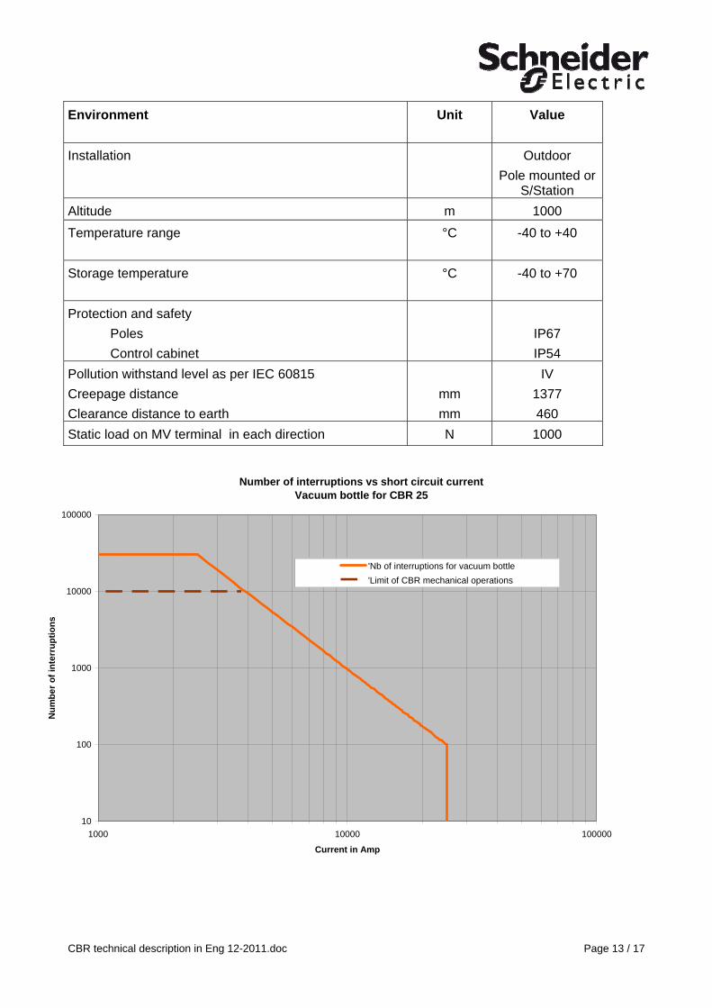
Environment
Unit Value
Installation Outdoor Pole mounted or
S/Station Altitude m 1000 Temperature range
°C -40 to +40
Storage temperature
°C -40 to +70
Protection and safety Poles Control cabinet
IP67 IP54
Pollution withstand level as per IEC 60815 Creepage distance Clearance distance to earth
mm mm
IV 1377 460
Static load on MV terminal in each direction N 1000
Number of interruptions vs short circuit currentVacuum bottle for CBR 25
10
100
1000
10000
100000
1000 10000 100000
Current in Amp
Num
ber o
f int
erru
ptio
ns
'Nb of interruptions for vacuum bottle'Limit of CBR mechanical operations
CBR technical description in Eng 12-2011.doc Page 13 / 17

CBR technical description in Eng 12-2011.doc Page 14 / 17
7 Maintenance and spare parts Pole interrupter: No maintenance Control cabinet: we recommend a preventive maintenance on the capacitors: replacement every 10 years. List of recommended spare parts based on 10 installed cabinets
Spare parts designation Control cabinet
Qty
Capacitors (value to be defined) 1
Relay (supply voltage to be defined) 1
Contactor (supply voltage to be defined) 1
ACE board card (supply voltage to be defined) 1
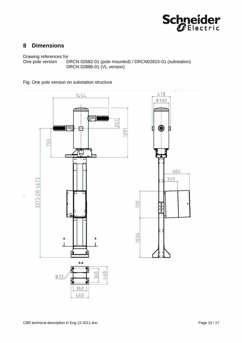
8 Dimensions Drawing references for One pole version DRCN 02682-01 (pole mounted) / DRCN02815-01 (substation) DRCN 02886-01 (VL version) Fig: One pole version on substation structure
CBR technical description in Eng 12-2011.doc Page 15 / 17

Fig: VL Version
CBR technical description in Eng 12-2011.doc Page 16 / 17

Fig: Two pole dimensions on s/station structure
CBR technical description in Eng 12-2011.doc Page 17 / 17