
!Other: !LOCT XLOIT PRocRAM
155
SEG SIMULATOR EXERCISE GUIDE NEXTETA EYW- R¡Ef SITE: DAEC Revision #: 0 LMS ID: PDA OPS ESG I LMS Rev. Date: N/A SEG TITLE: NRC lNlTlAL LICENSE EXAM, SCENARIO #l SEG TYPE: ! Training X Evaluation PRocRAM: !LOCT XLOIT !Other: DURATION: -90 minutes Developed by: lnstructor/Developer Date Reviewed by: lnstructor (l nstructional Review) Date Validated by: SME (Technical Review) Date Approved by: Training Supervision Date Approved by: Training Program Owner (Line) Date Filename: l_esg TR-AA-230-1 003-F06 Revision 0 Page 1 of 24
Transcript of !Other: !LOCT XLOIT PRocRAM

SEGSIMULATOR EXERCISE GUIDENEXTETAEYW-
R¡Ef
SITE: DAEC Revision #: 0
LMS ID: PDA OPS ESG I LMS Rev. Date: N/A
SEG TITLE: NRC lNlTlAL LICENSE EXAM, SCENARIO #l
SEG TYPE: ! Training X Evaluation
PRocRAM: !LOCT XLOIT !Other:
DURATION: -90 minutes
Developed by:
lnstructor/Developer Date
Reviewed by:
lnstructor (l nstructional Review) Date
Validated by:
SME (Technical Review) Date
Approved by:
Training Supervision Date
Approved by:
Training Program Owner (Line) Date
Filename: l_esg
TR-AA-230-1 003-F06 Revision 0 Page 1 of 24

SEGNRC lNlTlAL LICENSE EXAM, SCENARIO #1 Rev.0NEXTETA-EYærc-
SIMULATOR EXERCISE GUIDE REQUIREMENTSTerminal Objective This Evaluation Scenario Guide evaluates the Operators' ability to:
"Given the malfunctions presented in this ESG, the students will protect thepublic, protect plant personnel, and protect plant equipment, in accordancewith plant procedures."
Enabling Objectives:
Prerequisites:
Training Resources:
Evaluation Guide, no tasks are trained
None
A. SimulatorB. Evaluation teamC. Operations Management RepresentativeD, Simulator DriverE. Phone TalkerF. Exam Proctor for custody of the crew between scenariosG. Simulator Video recording equipment
References A, ARP 1C054 Rev. 82B. ARP 1C088 Rev.113C. AOP 410 Rev. 29D. ARP 1C084 Rev, 90E. ARP 1C23Ê' Rev. 19F. ARP 1C238 Rev.23G. Ol 734 Rev. 59H. AOP 644, Rev. 17L AOP 255.1, Rev.46J. AOP 255.2, Rev, 43K. EOP2 Rev. 18L. EOP 1 Rev.20M. ED Rev. 11
N. OP-AA-102-1003 Rev. 18O. lPOl 3 Rev. 152P. Ol 856.1, Rev.48Q. Ol 304.1, Rev.84R. O1304.2, Rev. 96S. Ol304.2QRC 1, Rev.0None
Evaluation Method: Dynamic Scenario graded in accordance with NUREG 1021 guidance
OperatingExperience
None
Risk SignificantOperator Actions
Protected Gontent:
Filename: 1_esg
TR-AA-230-1 003-F06 Revision 0 Page2 of 24

SEGNRC lNlTlAL LICENSE EXAM, SCENARIO #1 Rev.0NEXIETA-EYærc-
Direct Crew Response for performance of Emergency Depressurization6.78Direct Crew Response to Perform ALC with 1 core spray and 1 other ECCS pump available6.76Direct Crew Response to Perform ALC leg of EOP 1 when lnjection Systems are lined up6.74Direct Crew Response for performance of the PC/P leg of EOP 26.64Direct Crew Response for performance of the DW/T les of EOP 26.63Direct Crew Response for performance of RC/P leg of EOP 16.46Direct Crew Response for performance of initial EOP 1 actions (RC)6.45Direct Crew Response for performance of the RC/L leg of EOP 16.44Direct Crew Response for performance of Defeat 156.25Direct Crew Response to Perform EOP Defeat 116.21Direct Crew Response to Loss of River Water Supply5.15Direct Crew Response to Loss of 4160V Nonessential Power Condition5.08Direct Crew Responses to Loss of 1435.04Direct Crew Actions to Perform the lmmediate Operator Responses to a Reactor Scram4.21Determine operabilitv for TS required components1.02
Sen ior Reactor OperatorPerform an Emeroencv Depressurization Using SRVs95.80Perform ALC with 1 Core Sorav and 1 other ECCS pump available95.76Perform ALC leq of EOP 1 when lniection Systems are lined up and available95.74Perform PC/P leo of EOP 295.64Perform DWÆ leq of EOP 295.63Perform actions of RC/P of EOP 195.46Perform initial EOP 1 actions (RC)95.45Perform actions of RC/L of EOP 195.44Perform Defeat 1595.25Perform Defeat 1195.21Respond to Loss of River Water Supply94.1 5Perform the lmmediate Operator Responses to a Reactor Scram93.22Reset A/B or Startup Feed Regulating Valve Lockup45.21Transfer Essential Bus from Startup to Standbv Transformer15.10Remove the Startuo Transformer (1X3) from service14.16
Reactor OperatorTask TitleTask #
TASKS ASSOCIATED WITH SIMULATOR EXERCISE GUIDE
See CoverN/AI nitial development for
2017 NRC LOITExamination
lnitial development lor 2017NRC LOIT Examination
Rev. 0 See CoverDATEREVIEWER
AR/TWR#REASON FOR CHANGEDESCRIPTION OF CHANGE#DATEPREPARER
UPDATE LOG: lndicate in the following table any minor changes or major revisions (as defined in TR-M-230-1003)made to the material after initial approval. Or use separate Update Log form TR-AA-230-1003-F16.
Filename: 1_esg
TR-AA-230-1 003-F06 Revision 0 Page 3 of 24
SEGNRC lNlTlAL LICENSE EXAM, SCENARIO #1 Rev.0NEXTETA',YS*ø
RIET
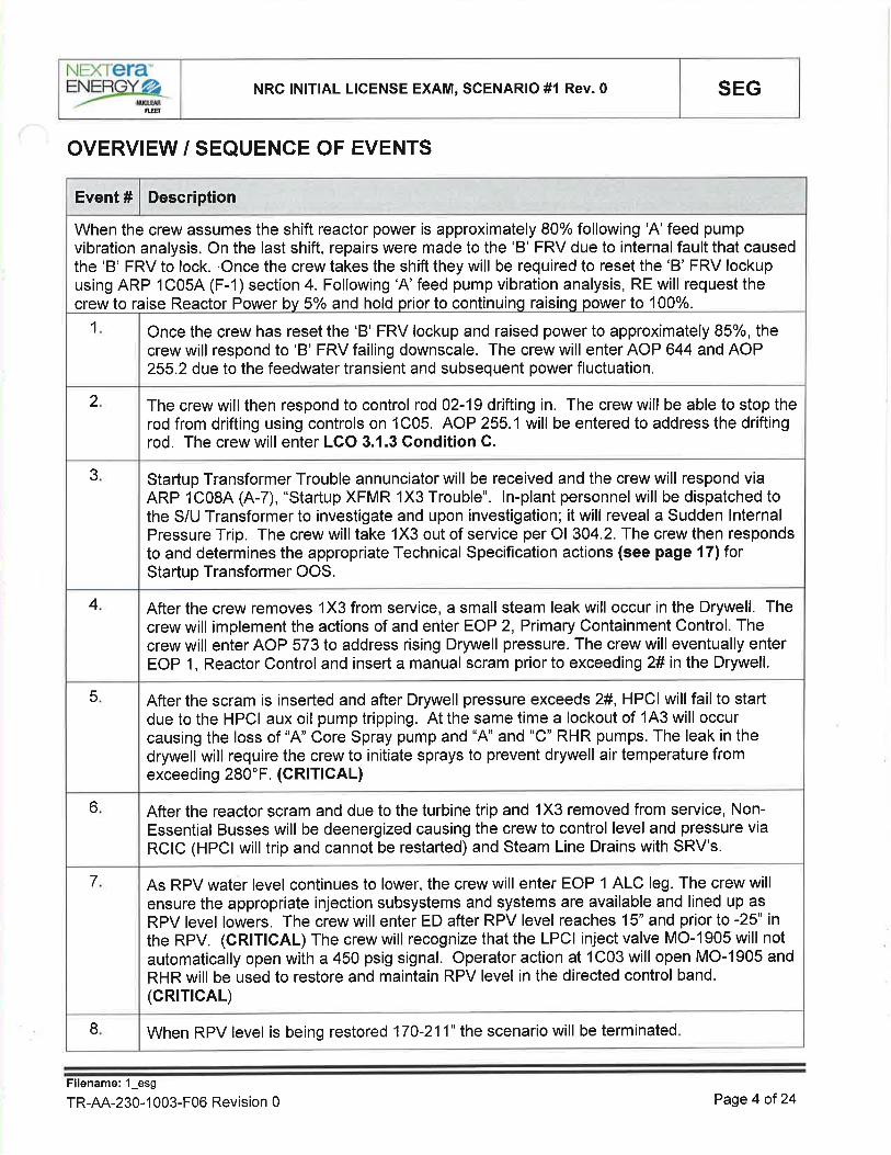
OVERVIEW / SEQUENCE OF EVENTS
When RPV level is being restored 170-211" the scenario will be terminatedI
As RPV water level continues to lower, the crew will enter EOP 1 ALC leg. The crew willensure the appropriate injection subsystems and systems are available and lined up as
RPV level lowers. The crew will enter ED after RPV level reaches 15" and prior to -25" inthe RPV. (CRITICAL) The crew will recognize that the LPCI inject valve MO-1905 will notautomatically open with a 450 psig signal. Operator action at 1C03 will open MO-1905 and
RHR will be used to restore and maintain RPV level in the directed control band.(cRrTrcAL)
7
After the reactor scram and due to the turbine trip and 1X3 removed from service, Non-Essential Busses will be deenergized causing the crew to control level and pressure viaRCIC (HPCI will trip and cannot be restarted) and Steam Line Drains with SRV's.
6
After the scram is inserted and after Drywell pressure exceeds 2#, HPCI will fail to startdue to the HPCI aux oil pump tripping. At the same time a lockout of 143 will occurcausing the loss of "A" Core Spray pump and "4" and "C" RHR pumps. The leak in thedrywell will require the crew to initiate sprays to prevent drywell air temperature fromexceeding 280"F. (CRITICAL)
5
After the crew removes 1X3 from service, a small steam leak will occur in the Drywell. Thecrew will implement the actions of and enter EOP 2, Primary Containment Control. Thecrew will enter AOP 573 to address rising Drywell pressure. The crew will eventually enterEOP 1, Reactor Control and insert a manual scram prior to exceeding 2# in the Drywell.
4
Startup Transformer Trouble annunciator will be received and the crew will respond viaARP 1C084 (A-7), "Startup XFMR 1X3 Trouble". ln-plant personnelwill be dispatched tothe S/U Transformer to investigate and upon investigation; it will reveal a Sudden lnternalPressure Trip. The crew will take 1X3 out of service per Ol 304.2. The crew then respondsto and determines the appropriate Technical Specification actions (see page 171forStartup Transformer OOS.
3
The crew will then respond to control rod 02-19 drifting in. The crew will be able to stop therod from drifting using controls on 1C05. AOP 255.1 will be entered to address the driftingrod. The crew will enter LCO 3.1.3 Gondition C.
2
Once the crew has reset the 'B' FRV lockup and raised power to approximately 85%, thecrew will respond to 'B' FRV failing downscale. The crew will enter AOP 644 and AOP255.2 due to the feedwater transient and subsequent power fluctuation.
1
When the crew assumes the shift reactor power is approximately 80% following 'A'feed pumpvibration analysis. On the last shift, repairs were made to the 'B' FRV due to internal fault that causedthe 'B' FRV to lock. .Once the crew takes the shift they will be required to reset the 'B' FRV lockupusing ARP 1C05A (F-1) section 4. Following 'A' feed pump vibration analysis, RE will request thecrew to raise Reactor Power by 5o/o and hold prior to continuing raising power to 100%.
DescriptionEvent #
Filename: 1_esg
TR-AA-230-1 003-F06 Revision 0 Page 4 of 24

SEGNRC lNlTlAL LICENSE EXAM, SCENARIO #l Rev.0NEXTETA-
=YSrgRIET
SIMULATOR SET UP INSTRUCTIONS1 . Set NRC Exam Security for the Simulator per QF-1071-08
2. Perform simulator set up per TDAP 1839 Attachment 2, Simulator Setup Checklist.
3, Load the saved lC (in folder with this ESG) to a SNAPSHOT
a. Reset to that SNAPSHOT.
b. Place the Simulator in RUN
OR4. Reset to lC 23, place the simulator in RUN and perform the following:
a. Raise power to approximately 80%b. lnsert fw16b and remove to lockup FRV'B'c. lnsert event triggers, malfunctions, overrides and remotes per the tables below.
5. RUN Schedule File "ESG_1.sch" and LEAVE lT RUNNING
6. Verify Malfunctions -7. Verify Remotes (Note that environmental remotes will already be timing)
L Verifv Overrides
9. Ensure MOL pull sheet is in the 1C058 hanging file.
10. Ensure EOOS has the same system status lineup as the start of the simulator scenario.
11. Setup control panel including equipment clearance tags, information tags, caution tags or othersite-specific devices used as an aid to the operator.
12. After going to run, to insert the 'B' FRV lockup perform the following:
a. lnsert fw16b to lockup FRV'B'b. Remove fwl6b in order to allow for the crew to reset
13. Provide appropriate shift turnover documentation.
a. Markup ARP 1C054 (F-1) as follows:
(1) Circle/slash the following sections/steps:
a) Section 1.0 - SteP 1.4
b) Section 2.0 - SteP 2,1
c) Section 3.0 - Steps 3.1,3.2 (a), Note, 3.7, 3,8, 3.10
(2) ONLY circle the following sections/steps:
a) Section 3.0 - 3.3
(3) N/A the following sections/steps:
a) Section 3.0 - 3.4, 3.5, 3,6, 3.8, 3.9
Filename: 1_esg
TR-AA-230-1 003-F06 Revision 0 Page 5 of 24

SEGNRC lNlTlAL LICENSE EXAM, SCENARIO #1 Rev.0NEXTETA-EYærc-
EVENT TRIGGER DEFINITIONS
MALFUNCTIONS:
C11AS3 NOTCH OVRRD EMER IN TO EMER-RODZDIRDCIlAS3(1) == 117
CV-4310 openZLOPCHS43l0(2) == 115
Pump 1P-2114 (Red) to RedZLOCSHS2103(4) == 111
HS-2256(2) AUX OrL PUMP 1P-218 L|TES (RED) TO ONZLOHPHS2256(2) == 15
Manually ActivatedManually Activated1,7,9,13
Trigger Word DescriptionTrigger Loqic StatementTrigger No
ACTIVEINACTIVE13CONTROL ROD DRIVES IN- ROD O2-19RD060219
0AS IS7:007FW REG VALVE CONTROLLER FAILURE
(AUTO)- FWRV BFW128
ACTIVEINACTIVE5HPC|Aux Oil Pump 1P218TripHP12Setup
ACTIVEACTIVELPCI B INJECT VALVE FAILS TO AUTOoPEN - MO-1905
STRH02Setup
ACTIVEACTIVELPCI A INJECT VALVE FAILS TO AUTOoPEN - MO-2003
STRHOlSetup
ACTIVEINACTIVE2 SEC114.16 KV/480V BUS FAULT - BUS 1A3EDOSCSetup
0.05030:00IRECIRC LOOP RUPT _ DESIGN BASESLOCA AT 1OO% - LOOP ARR15ASetup
ONCRYWOLF1:0011C08A (A-07) STARTUP XFMR 1X3
TROUBLEAN1C08A(7)Setup
FinalValuelnitialValueRampDelavETMalfunction TitleMalf. No.Time
Setup
Setup
REMOTES
ACTIVEINACTIVE5HS-2256(2) AUX OIL PUMP 1P-218 LITES(RED)DO-HP-033Setup
ACTIVEINACTIVE5HS-2256(1) AUX OrL PUMP 1P-218 LIrES(GREEN)DO-HP-032Setup
FinalValuelnitialValueRamoDelavETMalfunction TitleMalf. No.Time
SCHEDULE FILES
CONTROL ROD DRIVES IN- ROD02-19
Delete malfunction rd06021 917Setup
RECIRC LOOP RUPT - DESIGNBASES LOCA AT 100o/o - LOOP A
Modify rr15a to 1.5 in 90015Setup
DescriptionActionEvent@Time
ESG 1
Conduct simulator crew pre-scenario brief using TR AA-230-1007-F06, Simulator InstructorPre-Exercise Checklist.
lf surrogate operators are to be used, brief them using TR-AA-230-1007-F11, Surrogate BriefChecklist
Filename: 1_esg
TR-AA-230-1 003-F06 Revision 0 Page 6 of 24

SHIFT TURNOVER INFORMATION
SEGNRC lNlTlAL LICENSE EXAM, SCENARIO #l Rev.0NEXTETA-EYærc-
Monday, Day Shift
Warm summer day,77 degrees F, Severe Weather possibility later today
Approx
Protected train- "4"
Technical Specification Action statements in effect.
o DAEC is in compliance with all LCO's
Plant PRA/PSA Status including CDF/LERF & color
o CDF 2.95 E-6, 1 year to Yellow ICDP
o LERF 1.70 E-6, I year to yellow ILERP
Evolutions in progress or planned for upcoming shift:
o Repairs to an internal fault of the 'B' FRV controller are complete. Reset of lockup on 'B'FRV is expected upon conclusion of turnover.
o Power was lowered to perform 'A' feed pump vibration analysis. 'A' feed pump vibrationanalysis was completed on the last shift. The crew has been instructed to raise power.
o RE's have requested the crew to raise Reactor Power by 5o/o and hold prior to continuingraising power to 100%.
Comments, problems, operator workarounds, etc.
o One extra NSPEO available in Work Control
o Radwaste Operator is NSPEO qualified
a
a
a
o
a
o
a
a
Filename: 1_esg
TR-AA-230-1 003-F06 Revision 0 PageT of24
NÐflETA"
=Yæ6 NRC lNlTlAL L¡CENSE EXAM, SCENARIO #1 Rev.0 SEG
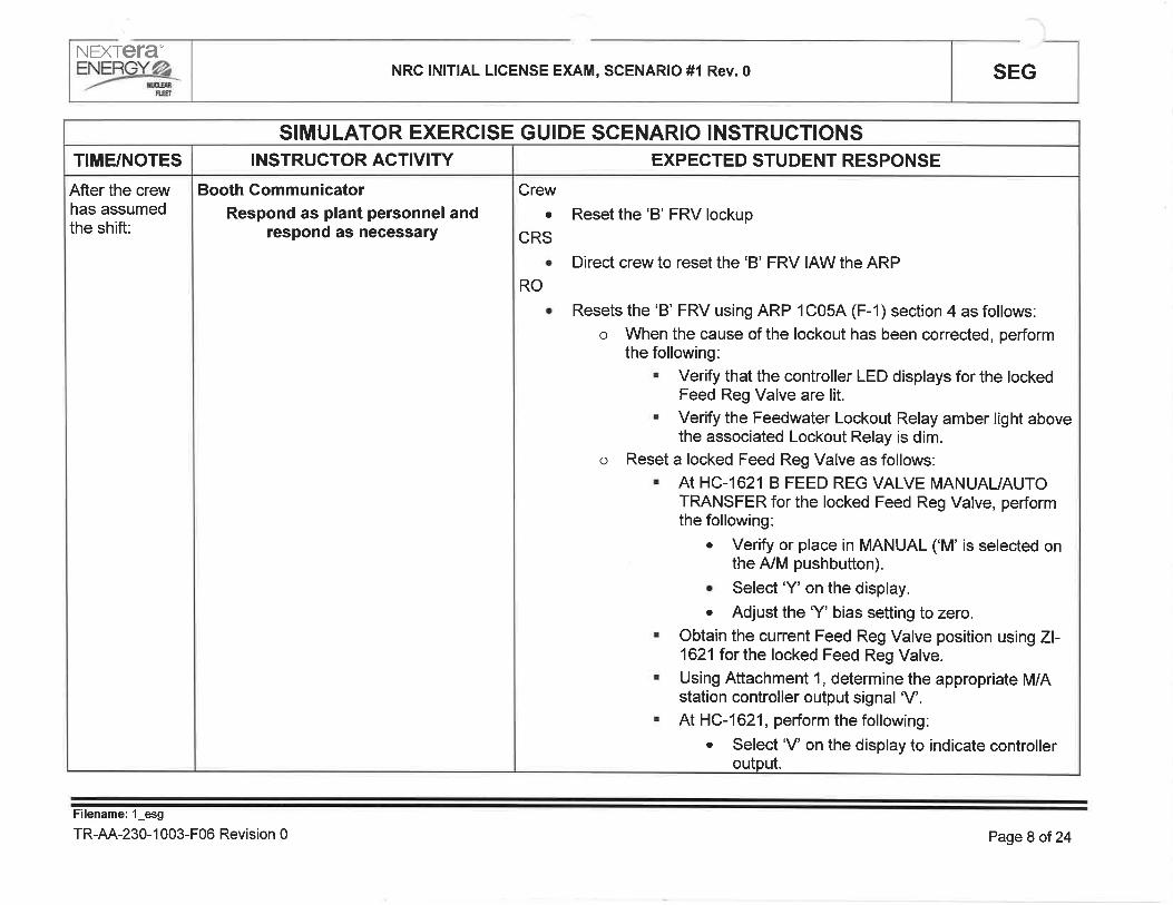
After the crewhas assumedthe shift:
TIME/NOTES
SIMULATOR EXERCISE GUIDE SCENARIO INSTRUCTIONS
Booth CommunicatorRespond as plant personnel and
respond as necessary
INSTRUCTOR ACTIVITY
Crewa Reset the 'B' FRV lockup
CRSa Direct crew to reset the 'B' FRV IAW the ARP
RO
o Resets the'B' FRV using ARP 1C054 (F-1) section 4 as follows:o When the cause of the lockout has been conected, perform
the following:. Verify that the controller LED displays for the locked
Feed Reg Valve are lit.. Verify the Feedwater Lockout Relay amber light above
the associated Lockout Relay is dim.
o Reset a locked Feed Reg Valve as follows:. At HC-16218 FEED REG VALVE MANUAUAUTO
TRANSFER for the locked Feed Reg Valve, performthe following:
. Verify or place in MANUAL ('M' is selected onthe A/M pushbutton).
o Select'Y' on the display.. Adjust the'Y' bias setting to zero.
. Obtain the cunent Feed Reg Valve position using Zl-16211or the locked Feed Reg Valve.
. Using Attachment 1, determine the appropriate M/Astation controller output signal 'V'.
. At HC-1621, perform the following:. Select'V' on the display to indicate controller
output.
EXPECTED STUDENT RESPONSE
Filename: l_esg
TR-AA-230-1 003-F06 Revision 0 Page 8 of 24

NÐflETA'NRC lNlT¡AL LICENSE EXAM, SCENAR¡O #l Rev.0 SEG
Cont
TIME/NOTES
SIMULATOR EXERCISE GUIDE SCENARIO INSTRUCTIONSINSTRUCTOR ACT¡VITY
RO
o
. Adjust 'V' to the value obtained from Attachment 1.
. Reset the lockout using HSS-1621.
. Verify the Feedwater Lockout Relay amber light is nolonger lit.
Transfer CV-1621 to AUTO as follows:. Verify the B FEED REG VALVE CONTROLLER HC-1621 is in MANUAL.. Select'V on the display for B FEED REG VALVECONTROLLER, HC-1621.. Select'V on the display for MASTER FEED REGVALVE CONTROLLER, LC-4577.. Match the Feedwater Reg Valve controller top meterdisplay with the MASTER FEED REG VALVECONTROLLER top meter display by adjusting thepotentiometer on HC-1 621.. Verify proper response of the Feedwater Regulatingvalve by monitoring Zl-1621.. SelectAUTO on HC-1621.. Select'S' on the display for B FEED REG VALVECONTROLLER, HC1621.
' Select'S' on the display for MASTER FEED REGVALVE CONTROLLER, LC-4577.
EXPECTED STUDENT RESPONSE
Filename: 1_esg
TR-AA-230-1 003-F06 Revision 0 Page 9 of 24

NEXTETA'
ñ.8
NRC lNlTlAL LICENSE EXAM, SCENARIO #l Rev.0 SEG
Raise power
lf contacted asorganization forassistance.
Booth CommunicatorRespond as plant personneland
respond as necessary
Raise reactor power by 5%
Raises reactor power by 5o/o IAW lPOl 3 and Ol 856.1 as follows:
o Monitor neutron monitoring instrumentation during control rodmovements.
o Verifies the following indications:. White backlight on the Rod Select pushbutton tums ON. On the Full Core Display, the white'XX-XX" select light
corresponding to the rod selected turns ON. On the Four Rod Group Display, the white SELECT light
turns ON denoting the position display for the selectedrod.
o Momentarily places the ROD MOVEMENT CONTROL in theOUT-NOTCH position and verifies:
. The green ROD lN light turns ON momentarily and thenturns OFF
o The red ROD OUT light turns ON after the green ROD lNlight turns OFF.
o The red ROD OUT light turns OFF. The amber ROD SETTLE light turns ON and then turns
OFFo The rod has been withdrawn as indicated on the Four Rod
Group Display
Direct and observe reactivity manipulations to achieve a 5o/o raise inreactor power
CREWa
RO
CRS
a
a
Filename: 1_esg
TR-AA-230-1 003-F06 Revision 0 Page 10 of 24

NEXTETA-
=Ystß'E.E1
NRC INITIAL LICENSE EXAM, SCENARIO #1 Rev. O SEG
After the crewhas reducedpower, resetthe'B'FRV,and at thedirection of theFloor lnstructor:
lf contacted asorganization forassistance:
lf contacted asoperators toinspect the 'B'FRV locally:
Two minutesafter being sentto investigate.B'FRV:
Simulator OperatorActivate ET 7.
This will activate FW128 for failure of 'B'FRV
Booth GommunicatorRespond as plant personnel and
respond as necessary
Booth GommunicatorAcknowledge communication
Booth Gommunicatorlnform control room that nothing
abnormal is seen at the FRV
Respond to 'B' FRV failure downscale
Crewa
ROo Assuming manual control of a malfunctioning system. Take manual control of the'B'Feedwater controller HC-1621 to
restore reactor water levelo Place one APRM recorder in each trip system to fast speed to
monitor for APRM undamped oscillations greater than normal.. Verify proper operation/indication of other systems and/or indications. Verify control rod positions are cotrect for the established sequence,
by using Rod Position Log.
. Verify thermal limits on the Official 3D Case.o When power is stabilized, plot location on the Stability Power / Flow
Map.
. Establish critical parameter monitoring of RPV Water Levelo Direct entering AOP 644. May direct entering AOP 255.2
CRS
Filename: 1_esg
TR-AA-230-1 003-F06 Revision 0 Page11o124
NEXIETA"
=YæX#- NRC lNlTlAL LICENSE EXAM, SCENARIO #1 Rev.0 SEG
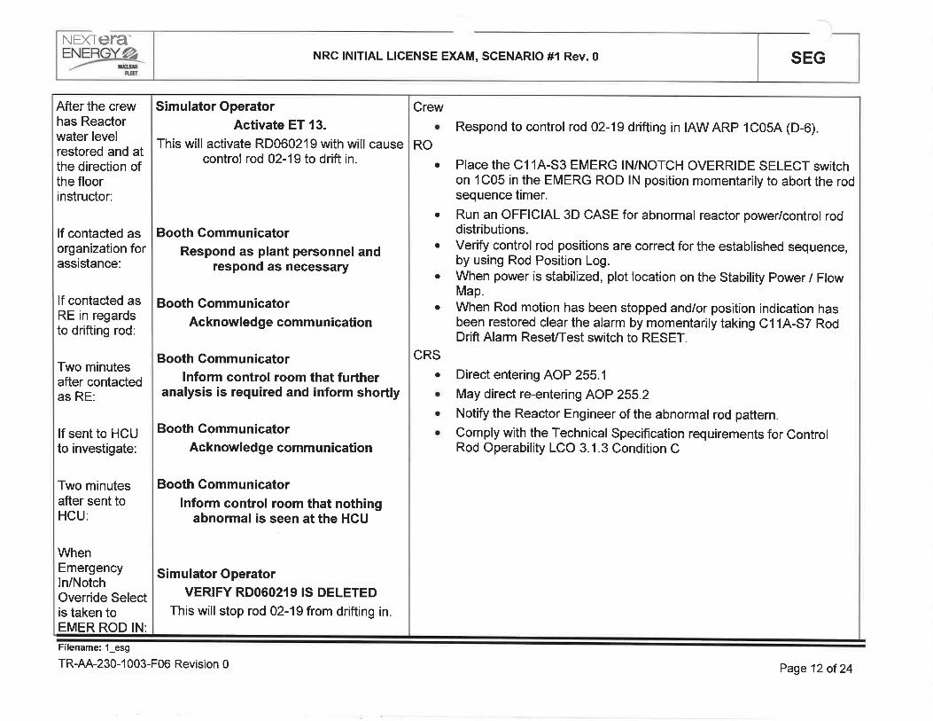
After the crewhas Reactorwater levelrestored and atthe direction ofthe floorinstructor:
lf contacted asorganization forassistance:
lf contacted asRE in regardsto drifting rod:
Two minutesafter contactedas RE:
lf sent to HCUto investigate:
Two minutesafter sent toHCU:
WhenEmergencyln/NotchOverride Selectis taken toEMER ROD IN:
Simulator OperatorActivate ET 13.
This will activate RD060219 with will causecontrol rod 02-19 to drift in.
Booth GommunicatorRespond as plant personnel and
respond as necessary
Booth GommunicatorAcknowledge commu nication
Booth Gommunicatorlnform control room that further
analysis is required and inform shortly
Booth GommunicatorAcknowledge communication
Booth Communicatorlnform control room that nothing
abnormal is seen at the HCU
Simulator OperatorVERIFY RDO6O2I9 IS DELETED
This will stop rod 02-19 from drifting in
Respond to control rod 02-19 drifting in IAWARP 1C05A (D-O).
Place the C11A-S3 EMERG IN/NOTCH OVERRIDE SELECT switchon 1C05 in the EMERG ROD lN position momentarily to abort the rodsequence timer.
Run an OFF¡CIAL 3D CASE for abnormal reactor power/control roddistributions.Verify control rod positions are correct for the established sequence,by using Rod Position Log.When power is stabilized, plot location on the Stability Power / FlowMap.When Rod motion has been stopped and/or position indication hasbeen restored clear the alarm by momentarily taking C11A-S7 RodDrift Alarm ReseUTest switch to RESET.
o Direct entering AOP 255.1
. May direct re-entering AOP 255.2
. Notify the Reactor Engineer of the abnormal rod pattern.
. Comply with the Technical Specification requirements for ControlRod Operability LCO 3.1.3 Condition C
Crewa
RO
a
a
a
a
a
CRS
Filename: l_esg
TR-AA-230-1 003-F06 Revision 0 Page 12 of 24

NEX|cra'eNEBgr@r NRC lNlTlAL LICENSE EXAM, SCENARIO #l Rev.0 SEG
ffi
Loss of 1X3
Afterinvestigation oftrip of 1Ê.412and tech speccall and at thedirection of thefloor instructor:
1 min. after ET1 goes active:
Whencontacted toinvestigate 1X3alarm:
2 min. after toldto investigate1X3 alarm:
Simulator Operatorlnsert ETI
This inserts AN1C08A(7), S/U Xfmr troublealarm after 1:00 minute time delay.
Simulator OperatorVerify lC08A [A-71 annunciates.
Booth GommunicatorAcknowledge request.
Booth Gommunicatorlnform Control Room there is a Sudden
lnternal Pressure Trip Alarm in.
Crew. lmplement actions of ARP 1C084 (A-7) Startup XFMR 1X3 Trouble.RO
. Send an Operator locally to 1X3 Alarm Cubicle to determine the cause ofthe alarm.
o With the aid of Table 1, take the appropriate Corrective Action.. Take 1X3 out of service per Ol 304.1 and O1304.2, (or Ol 304.2 ORC)
CRS
r Contact the Electrical Maintenance Supervisor to perform a portable GasAnalysis of the combustible gas.
o Direct taking out 1X3 out of service per Ol 304.2 (or Ol 304.2 ORC)
Filename: 1_esg
TR-AA-230-1 003-F06 Revision 0 Page 13 of24

NEXTETA"
=YSxø_ffi
NRC lNlT¡AL LICENSE EXAM, SCENAR¡O #1 Rev.0 SEG
After crewreceives reportthat 1X3 has hi-combustiblegas and rising:
lflwhencontacted toverifyswitchgearrooms clear:
lfA|t/hencontacted asorganization:
Booth CommunicatorAcknowledge request.
Booth GommunicatorAc knowled ge i nformation/req uests
Crewo Take 1X3 out of service IAW Ol 304.2 and Ol 304.2 QRCIRO
. Using Ol304.2QRC1:. Transfer 143 to the Standby Transformer by performing the following:
r Place BUS 143 TRANSFER switch in MANUAL.o lnsert the handle in the SYNCHRONIZE switch for 4l(/ BREAKER
14301 STANDBY TRANSFORMER TO BUS 143, and place in theON position.
. Verify that the synchroscope indicates near 12 o'clock and notmoving with both white (differential phase voltage) indicating lightsOFF.
. Place the control switch 4KV BREAKER 14301 STNDBYTRANSFORMER TO BUS 143 momentarily to the CLOSE position.
. Verify BUS 143 STANDBY AMPERES greater than zero amps.r Place the control switch 4KV BREAKER 14302 STARTUP
TRANSFORMER TO BUS 143 momentarily in the TR|P position.. Place the SYNCHRONIZE switch for4KV BREAKER 14301
STANDBY TRANSFORMER TO BUS 143 in the OFF position.o Place BUS 143 TRANSFER switch in AUTO.
Filename: 1_esg
TR-AA-230-1 003-F06 Revision 0 Page 14 of 24

F.,ET
N=XTera"
=YSre_ NRC lNlTlAL LICENSE EXAM, SCENARIO #l Rev.0 SEG
RO
Using O1304.2 QRCI:o Remove startup Transformer 1X3 from service by performing the
following:
o lf required, transfer Bus 141 to the Aux Transformer per Ol 304.1.. lf required, transfer Bus 142 to the Aux Transformer per Ol 304.1.. Place the STARTUP TRANSFORMER J BREAKER (OCB SS50)
control switch momentarily in the TRIP position.o Place the STARTUP TRANSFORMER K BREAKER (OCB 5560)
control switch momentarily in the TRIP position.
a
RO. Using Ol304.2QRC1:
o Transfer 1A4 to the Standby Transformer by performing the following.o Place BUS 144 TRANSFER switch in MANUAL.. Insert the handle in the SYNCHRONIZE switch for 4KV BREAKER
1A401STANDBY TRANSFORMER TO BUS 144, and ptace in theON position.
. Verify that the synchroscope indicates near 12 o'clock and notmoving with both white (differential phase voltage) indicating lightsOFF.
o Place the control switch 41(/ BREAKER 14401 STNDBYTRANSFORMER TO BUS 144 momentarily to the CLOSE position
. Verify BUS 144 STANDBY AMPERES greater than zero amps.
. Place the control switch 4KV BREAKER 14402 STARTUPTRANSFORMER TO BUS 1A4 momentarity in the TRtp position.
. Place the SYNCHRONIZE switch for 4l(/ BREAKER 1A401STANDBY TRANSFORMER TO BUS 144 in the OFF position.
. Place BUS 1A4 TRANSFER switch in AUTO.
Filename: 1_esg
TR-AA-230-1 003-F06 Revision 0 Page 15 of 24

NEXìttfa"ENE@
-/- xEEaNRC INITIAL LICENSE EXAM, SCENARIO #l Rev.0 SEG
nEr
Floor lnstructorGheck that CRS is using Ol 304.2
sect¡on "TFIANS FERRI NGESSENTTAL BUS 1A3[4] FROM
STARTUP TO STANDBYTRANSFORMER" for Tech Spec call.
CRS. Using O1304.2 section "TRANSFERRING ESSENTIAL BUS 143[4]
FROM STARTUP TO STANDBY TRANSFORMER'':. lf in Mode 1,2, ot 3, verify the following Tech Spec conditions are
entered:o T.S. 3.8.1 Condition A for Standby XFMR Offsite Circuit. T.S. 3.8.1 Condition B for associated SBDG
¡ lf the Startup XFMR Offsite Circuit is currently inoperable, then enterthe following additional Tech Spec conditions:o T.S. 3.8.1 Condition C for both Offsite Circuits inoperable. T.S. 3.8.1 Condition F (three AC sources inoperable). T.S. 3.0.3 (per 3.8.1F)
Filename:'l_esg
TR-AA-230-1 003-F06 Revision 0 Page 16 of 24

After 1X3 istaken out ofservice andTech Spec hasbeen discussedand at thedirection of thefloor instructor:
After the crewtakes HS-4310to Auto Open:
Whencontacted asITC Midwest:
lf contacted astheorganization forassistance:
Simulator Operatorlnsert ET 9
This will start a drywell leak.
Simulator OperatorVerify ET 15 goes AGTIVE
This will increase the size of the leakleading to the crew to scram.
Booth CommunicatorAcknowledge notification.
Booth GommunicatorAcknowledge request.
Crew
Respond to a coolant leak in containment.a
RO
CRS
¡ Monitor outside barometric pressure utilizing Computer Point M000 todetermine if weather conditions are causing a change in indicateddrywell pressure.
. Verify RIM-91844 and RIM-91848, NW and South Drywell Area HiRange Rad Monitors, are reading less than 20R/hr.
¡ Start one train of the Standby Gas Treatment System.. Depress the DIV 1 Reset and DIV 2 Reset pushbuttons to clear the
isolation signals.r Position switches at 1C03 as follows:
o HS-4303 Outbd DrywellVent lsol CV-4303 Auto Openo HS-4310 lnbd DW Vent Bypass lsol CV-4310 Auto Openo HS-4302 lnbd DrywellVent lsol CV-4302 Auto Open
a Directs enterAOP 573
CREWo Using Ol 304.1 section "REMOVING THE STARTUP TRANSFORMER
(1X3) FROM SERV|CE":. Verify Essential Busses 143 and 1A4 are transferred to the Standby
Transformer or SBDG per Ol 304.2.
. Verify Non-essential Busses 141 and 1A2 are transfened to theAuxiliary Transformer per Ol 304.1.
. Notify ITC Midwest that the Startup Transformer (1X3) will/hasbe/been removed from service.
. Record the time ITC Midwest was notified that the StartupTransformer was removed from service in the Operating Log.
SEG
Filename: 1_esg
TR-AA-230-1 003-F06 Revision 0 Page 17 of24
NÐC ETA"NRC lNlTlAL LICENSE EXAM, SCENARIO #1 Rev.0 SEG
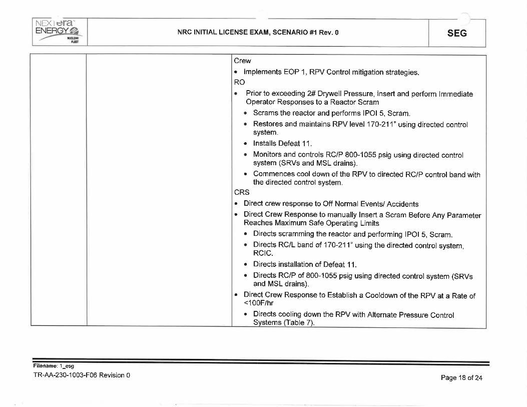
Crew. lmplements EOP 1, RPV Control mitigation strategies.RO
o Prior to exceeding 2# Drywell Pressure, insert and perform lmmediateOperator Responses to a Reactor Scram. Scrams the reactor and performs lPOl 5, Scram.o Restores and maintains RPV level 170-211" using directed control
system.. lnstalls Defeat 11.
o Monitors and controls RC/P 800-1055 psig using directed controlsystem (SRVs and MSL drains).
¡ Commences cool down of the RPV to directed RC/P control band withthe directed control system.
CRSo Direct crew response to Off Normal Events/ Accidentso Direct Grew Response to manually lnsert a Scram Before Any Parameter
Reaches Maximum Safe Operating Limits¡ Directs scramming the reactor and performing lpOl S, Scram.o Directs RC/L band of 170-211" using the directed control system,
RCtC.
. Directs installation of Defeat 11.
o Directs Rc/P of 800-1055 psig using directed control system (sRVsand MSL drains).
¡ Direct Grew Response to Establish a cooldown of the Rpv at a Rate of<100F/hr
¡ Directs cooling down the RPV with Alternate pressure ControlSystems (Table 7).
Filename: l_esg
TR-AA-230-1 003-F06 Revision 0 Page 18 oî 24

NÐflETA"
=Yzaxç NRC INITIAL LICENSE EXAM, SCENARIO #1 Rev.0 SEG
After DrywellPressureexceeds 2 psig
lf contacted toinvestigate 1P-218 breaker:
Two minutesafter 1P-218investigation:
Simulator OperatorVerify ET 5 AND ll goes active
This will insert HP12 to trip the HPCIAuxOil Pump and ED08C to Lockout Bus 143
Booth GommunicatorAcknowledge request.
Booth Communicatorlnform control room that breaker for 1P-
218 is tripped on ground fault.
Crew. lmplements the mitigation strategies of EOP 2, Primary Containment
Control
RO
. lnforms the CRS of containment parameters including parameter name,value and trend.
o lnstalls Defeat 4.
. Utilizes Ol 149 QRC to spray the torus.o Utilizes Ol 149 QRC to spray the drywell.o Utilizes OI 149 QRC to establish torus cooling.CRS. Performs a crew update of entry into EOP 2 due to Drywell Pressure.. Obtains containment parameters.
o Directs installation of Defeat 4.
o Directs spraying the torus after confirmation that torus pressure is greaterthan 2 psig.
o Directs spraying the drywell before drywell temperature reaches 2A0F.(cRrTrcAL). Verifies torus water level less than 13.5 ft.o Verifies plot of drywell temperature and drywell pressure on the DWSIL
curye allows drywell sprays.. Verifies recirculation pumps are secured.
o Directs maximizing torus cooling.. Placekeeps in EoP 2 to the applicable wAtr UNT|L steps in T/L (T/L-3
and T/L 10), T/T (T/T-6), DWT (DWT-6) and PC/P (PC/p-7) tegs
Filename: 1_esg
TR-AA-230-1 003-F06 Revision 0 Page 19 of 24

NÐflETA'
ryÊYk NRC ¡NlTlAL LICENSE EXAM, SCENAR¡O #l Rev.0 SEG
ALC Crew. lmplements that mitigation strategies of the ALC contingency of EOP 1
RO
o Lockouts ADS.
¡ Attempts to restore and maintain RPV level above +15"
o Maximizes injection with CRD in accordance with AIP 407.o lnjects with SBLC in accordance with AIP 406.
o Verifies injection subsystems can be lined up for injection. Verifies at least one injection subsystem lined up with a pump running.CRSo Directs ADS lockout.o Directs RPV level bands as RPV level lowerso Directs maximizing injection with CRD in accordance with AIP 407.o Directs injection with SBLC in accordance with AIP 406.¡ Ensures injections subsystems can be lined up for injection.o Waits for RPV levelto drop to +15"
. Ensures at least one injection subsystem lined up with a pump running
. Before RPV level reaches -25" performs an Emergency Depressurization
Filename: 1_esg
TR-AA-230-1 003-F06 Revision 0 Page2} of24

F.EI
NEXTETA"ENqllq.a
_/- nffiNRC |N¡TIAL L¡CENSE EXAM, SCENARIO #l Rev.0 SEG
EmergencyDepress.:
Crew. After RPV level reaches +15" enters and implements the mitigation
strategies of EOP ED. (CRITICAL). Places handswitch of the first SRV to OPEN prior to RPV level reaching
-25"
RO
. Perform Actions of EOP 1 ALC and ED.
o lnstalls Defeat 11.
. Perform an Emergency Depressurization Using SRVs.. Open4ADS SRVs
. Recognizes MO-1905 does not automatically open at 450 psig and takesaction at 1C03 to open MO-1905. (cRlTlCAL)
CRSo Direct Crew Response for performance of EOP 1 ALC and ED
o Directs installation of Defeat 11.
o Verifies all control rods inserted to at least position 00.o Verifies torus water level above 4.5 feet
o Direct Crew Response to Perform an Emergency Depressurization UsingSRVsa Directs open ing 4 ADS SRVs
Filename: 1_esg
TR-AA-230-1 003-F06 Revision 0 Page21 of24
NÐC ETA'
=YINK NRC lNlTlAL LICENSE EXAM, SCENARIO #1 Rev.0 SEG
Filename: 1_esg
TR-AA-230-1 003-F06 Revision 0
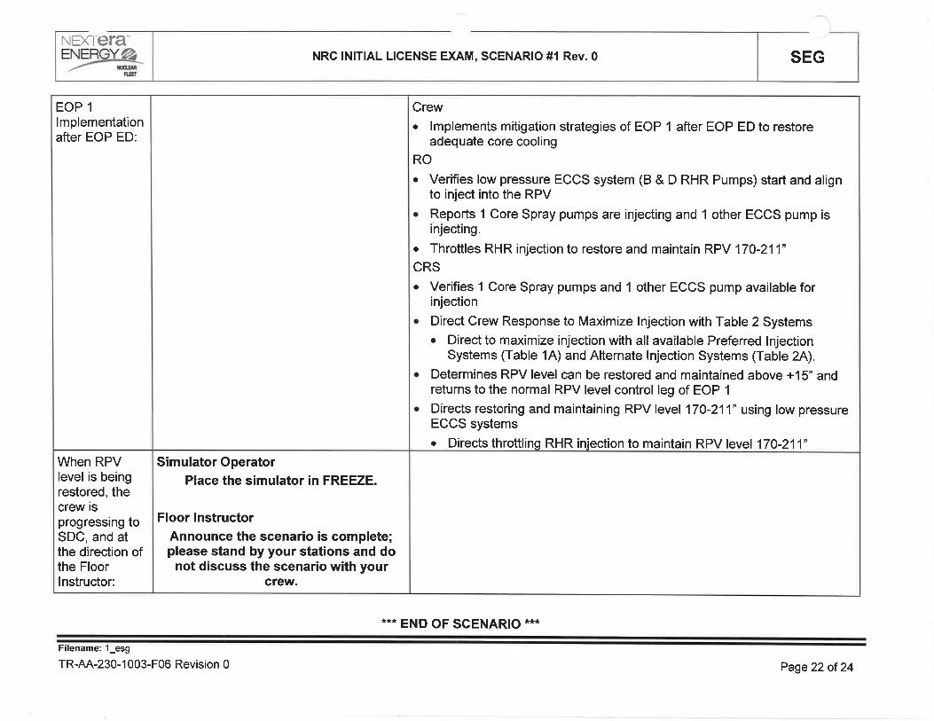
When RPVlevel is beingrestored, thecrew isprogressing toSDC, and atthe direction ofthe Floorlnstructor:
EOP 1
lmplementationafter EOP ED:
Simulator OperatorPlace the simulator in FREEZE.
Floor lnstructorAnnounce the scenario is complete;please stand by your stations and do
not discuss the scenario with yourcrew.
Crew. lmplements mitigation strategies of EOP 1 after EOP ED to restore
adequate core cooling
RO
o Verifies low pressure ECCS system (B & D RHR Pumps) start and alignto inject into the RPV
. Reports 1 Core Spray pumps are injecting and 1 other ECCS pump isinjecting.
o Throttles RHR injection to restore and maintain RPV 170-211"CRSo Verifies 1 Core Spray pumps and 1 other ECCS pump available for
injectiono Direct Grew Response to Maximize lnjection with Table 2 Systems
o Direct to maximize injection with all available Preferred lnjectionSystems (Table 1A) and Alternate lnjection Systems (Table 2A).
. Determines RPV level can be restored and maintained above +1S" andreturns to the normal RPV level control leg of EOP 1
o Directs restoring and maintaining RPV level 170-211" using low pressureECCS systems¡ Directs throttling RHR injection to maintain RPV level 170-211'
*** END OF SCENARIO ***
Page22 of 24

SEGNRC lNlTlAL LICENSE EXAM, SCENARIO #1 Rev.0NEXTETA-EYæT6:
QUANTITATIVE ATTRI BUTES
Malfunctions:Before EOP Entry:
1. 'B' FRV fail downscale
2. Control Rod Drift
3. S/U Xfmr Hi Combustible Gas
After EOP Entry:
1. HPCI Trip Upon Startup
2. Loss of 1A3
3. Drywell Steam Leak
Abnormal Events:1. AOP 644
2. AOP 255.2
3. AOP 255.1
Maior Transients:1. LOCA in DW
2. ALC
3. ED
Critical Tasks:
1. #22: BEFORE drywell temperature reaches 280"F and WHILE in the safe region of theDWSIL, THEN initiate drywell sprays. {BWROG: N/A}
2. #1 : lF the reactor is shutdown under all conditions and RPV level drops to +15", THENperform Emergency RPV Depressurization before RPV level reaches -25".
{BWROG: RPV 1.1}
3. #2: lF the reactor is shutdown under all conditions, THEN crew actions must be taken torestore and maintain RPV level for adequate core cooling. {BWROG: RPV 1.2}
Filename: 1_esg
TR-AA-230-1 003-F06 Revision 0 Page23 oÍ 24

SEGNRC lNlTlAL LICENSE EXAM, SCENARIO #1 Rev. 0NEXTETA"EW
n¡€f
CREW GRADING ATTACHMENT
ESG 1 Rev. 0 Date
Management Representative/Lead Evaluator
Crew Critical Tasks
B.O.P
1C03
1C05
STA
CRS
OSM
EvaluatorPositionOperator Name
3. lF the reactor is shutdown under all conditions, THEN crew actionsmust be taken to restore and maintain RPV level for adequate corecooling.
2. lF the reactor is shutdown under all conditions and RPV level drops to+15", THEN perform Emergency RPV Depressurization before RPVlevel reaches -25".
1. BEFORE drywell temperature reaches 280'F and WHILE in the saferegion of the DWSIL, THEN initiate drywell sprays.
UNSATSATTask Statement
Filename: 1_esg
TR-AA-230-1 003-F06 Revision 0 Page24 of 24

STP
Page
Rev.
3.8.1-01
1of115
SURVEILLANCE TEST PROCEDURE
TITLE: OFFSITE POWER SOURCESDAECDUANE ARNOLD ENERGY CÊNTER
Usage Level
CONTINUOUS
Record the following: Date / Time: lnitials
NoTE: User shall perform and document a Temp lssue / Rev. Check to ensure revision is current,in accordance with procedure use and adherence requirements.
Prepared By: DatePrint Signature
Approved By I DatePrint Signature
PROCEDURE APPROVAL
I
Reviewed By: I Date:
Print Signature
Reviewed By: I Date:
Print Signature
Reviewed By: DatePrint Signature
cRoss-DrscrPLrNE REVTEW (As REQUTRED)

STP
Page
Rev.
3.8.1-01
2of115
SURVEILLANCE TEST PROCEDURE
TITLE: OFFSITE POWER SOURCESDAECDUANE ARNOLD ENERGY CËNTER
1.0
1.1
1.2
PURPOSE
This STP verifies correct breaker alignment and indicated power availability for each offsitecircuit capable of supplying the onsite Class 1E AC Electrical Distribution System.
This STP is routinely performed with both offsite circuits available, or in response to thecondition of one offsite circuit or one diesel generator inoperable.
BRIEFING ¡NFORMATION
PERFORMANCE I NFORMATION
2.1.1 Section 7.0 of this STP contains two (2) sections that cover the anticipatedconditions under which this STP will be performed. The STP is organized as follows
One Offsite Circuit Available7.2
Both Offsite Circuits Available7.1
ConditionsSect.
Only one of these sections should need to be performed to satisfy the performancerequirements associated with this STP. All steps within a particular section are to beperformed in sequence and the STP steps carried through to completion, unlessstated othenruise.
2.1.2 Personnel recommended to perform this procedure
1 Operations
2.1.3 Special Test Equipment required :
1 Marking Pen (Do not use light colored hi-lighters or markers, Use only darkcolored pens or markers. See General Caution 2.2.1).
2.2 GENERAL CAUTIONS
2.2.1 lf utilizing a paper copy of this surveillance, do not use light colored hi-lighters ormarkers to record data, outline configurations on drawings or to initial steps.Light-colored hi-lighters are not dark enough to reproduce adequately as the QArecord. Not applicable when using electronic copies.
2.3 SPECIAL PRECAUTIONS
2.3.1 None
2.0
2.1

STP
Page
Rev.
3.8.1-01
3 of 11
5
SURVEILLANCE TEST PROCEDURE
TITLE: OFFSITE POWER SOURCESDAECDUANE ARNOLD ENERGY CENTER
3.0
3,1
3.2
REFERENCES
Applicable drawings:
3.1.1 BECH-E001<1>
3.1.2 BECH-E005
3.1.3 BECH-E023
Supporting documents:
3.2.1 NG-97-2146
GENERAL INSTRUCTIONS
Steps marked with a "TS" immediately to the right of the step sign-off line are required byTechnical Specifications. lf these steps do not meet their acceptance criteria or cannot beperformed, a NRC reportable condition may exist and shall be reported to the Control RoomSupervisor (CRS) immediately.
lf any equipment or components are observed to be in a state of disrepair during theperformance of this STP, appropriate corrective maintenance shall be initiated.
An Action Request (AR) should be completed for any problems encountered with "TS" markedsteps during the performance of this test.
The CRS shall be notified immediately and the appropriate Limiting Conditions for Operationsection of Technical Specifications referred to whenever problems are encountered during theperformance of this STP,
4.0
4.1
4.2
4.3
4.4
5.0 APPENDICES
None
INITIALSPerformance Date:Prerequisites
STP
Page
Rev.
3.8,1-01
4of115
SURVEILLANCE TEST PROCEDURE
TITLE: OFFSITE POWER SOURCESDAECDUANE ARNOLO ENERGY CENTER
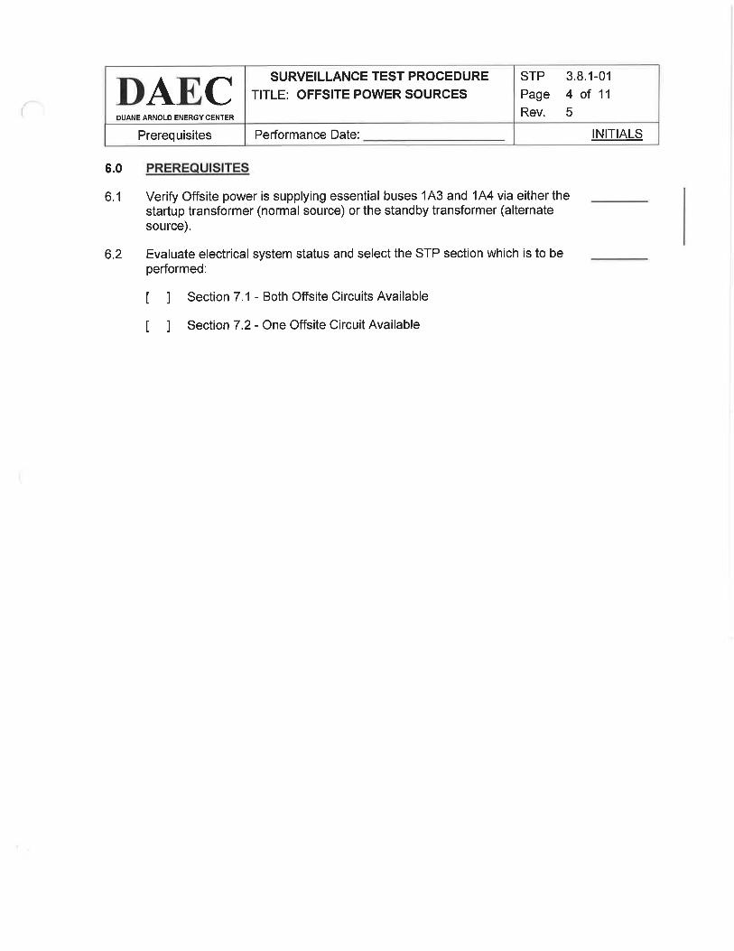
6.0
6.1
PREREQUISITES
Verify Offsite power is supplying essential buses lA3 and 144 via either thestartup transformer (normal source) or the standby transformer (alternatesource).
6.2 Evaluate electrical system status and select the STP section which is to beperformed:
t I Section 7.1 - Both Offsite Circuits Available
t I Section 7.2 - One Offsite Circuit Available

INITIALSPerformance Date:
STP
Page
Rev.
3.8.1-01
5 of 11
5
SURVEILLANCE TEST PROCEDURE
TITLE: OFFSITE POWER SOURCESDAECDUANE ARNOLD ENERGY CENTER
7.0
7.1
PROCEDURE
BOTH OFFSITE CIRCUITS AVAILABLE
NOTElnformation from the Load Dispatcher may be needed to complete the followingstep.
7 .1.1 Using the guidance below and Attachment 1, identify twoseparate circuits available to transmit power from the offsitepower sources to the essential buses.
a. Based on equipmenUsystem lineup and operational status,use a dark marking pen to trace an available circuit from anoffsite power source to the Startup Transformer supplybreakers, 14302 and 14402.
b. Based on equipmenUsystem lineup and operational status,use a dark marking pen to trace a second circuit from anotheroffsite power source to the Standby Transformer supplybreakers, 14301 and 1A401 such that it does not share anylines, buses, or transformers in common with the circuit to theStartup Transformer supply breakers.
c. Based on equipmenUsystem lineup and operational status,complete the electrical lineup by using a dark marking pen totrace the connections from each Essential Bus (143 and 144)to the Startup or Standby Transformer supply breakercurrently feeding the bus.
7.1.2 Confirm two (2) independent offsite circuits are available byinitialing one of the two sets of statements below and N/A'ing theother:
a. A circuit exists from an offsite power source, through theStartup Transformer and its supply breakers to both 143 and144 essential buses;
AND
A second independent circuit exists from a ditferent offsitesource, through the Standby Transformer to its supplybreakers.
TS

INITIALSPerformance Date:
STP
Page
Rev.
3.8.1-01
6 of 11
5
SURVEILLANCE TEST PROCEDURE
TITLE: OFFSITE POWER SOURCESDAECDUANE ARNOLD ENERGY CENTER
b. A circuit exists from an offsite power source, through theStartup Transformer and one of its supply breakers to eitherthe 1A3 or 1A4 essentialbus;
AND
A second independent circuit exists from a different otfsitesource, through the Standby Transformer and one of itssupply breakers to the other essential bus.
(PRTNT / SrGN)
I
TS
I
IPerformed by: Date: Time: lnit.

INITIALSPerformance Date
STP
Page
Rev.
3.8.1-01
7of115
SURVEILLANCE TEST PROCEDURE
TITLE: OFFSITE POWER SOURCESDAE,CDUANE ARNOLD ENERGY CENTER
7.2 ONE OFFSITE CIRCUIT AVAILABLE
NOTElnformation from the Load Dispatcher may be needed to complete the followingstep.
7.2.1 Using the guidance below and Attachment 1, identify a circuitavailable to transmit power from an offsite power source to theessential buses.
a. Based on equipmenUsystem lineup and operational status,use a dark marking pen to trace an available circuit from anoffsite power source to the Startup Transformer supplybreakers, 14302 and 1A402 or Standby Transformer supplybreakers, 14301 and 14401.
b. Based on equipmenVsystem lineup and operationalstatus,complete the electrical lineup by using a dark marking pen totrace the connections from the required Essential Bus(es)(143 and/or 1A4) to the Startup or Standby Transformersupply breakers.
7.2.2 If in Mode 1,2 or 3, mark Step 7.2.4 "N/A" and proceed with theperformance of Step 7.2.3.
OR
lf in Mode 4 or 5, or during movement of irradiated fuelassemblies in the Secondary Containment, mark Step 7.2.3'N/4"and proceed with the performance of Step 7.2.4.
7.2.3 Confirm an offsite circuit exists from an offsite power source,through either the Startup or Standby Transformer and itsassociated supply breakers to both 143 and 144 essential buses.
ÏS

INITIALSPerformance Date:
STP
Page
Rev.
3.8.1-01
I of 11
5
SURVEILLANCE TEST PROCEDURE
TITLE: OFFSITE POWER SOURCESDAECDUANE ARNOLO ENERGY CENTER
7.2.4 Confirm an offsite circuit exists from an offsite power source byinitialing one of the two statements below and "N/A'ing" the other:
a. An offsite circuit exists from an offsite power source, througheither the Startup or Standby Transformer and its associatedsupply breakers to both 1A3 and 144 essential buses.
b. An offsite circuit exists from an offsite power source, througheither the Startup or Standby Transformer and one of itsassociated supply breakers to the required 143 or 144essential bus.
(PRTNT / SrGN)
TS
TS
I
I
IPerformed by Date Time: lnit.
ir

INITIALSPerformance Date:
STP
Page
Rev.
3.8.1-01
9 of 11
5
SURVEILLANCE TEST PROCEDURE
TITLE: OFFSITE POWER SOURCESDAECDUANE ARNOLD ENERGY CENTER
8.0
8.1
8.2
8.3
ACCEPTANCE CRITERIA
lndicate the reason for performing the STP:
t I Routine with both offsite circuits available
t 1 Routine with one offsite circuit available while in Mode 4 or 5 orduring movement of irradiated fuel assemblies in the secondarycontainment
t 1 Action in response to one offsite circuit inoperable
t I Action in response to one diesel generator inoperable
t I Other, explain below:
All Technical Specification required items, as indicated by "TS", have beenperformed satisfactorily:
8.2.1 Section 7.1 ( ) YES ( ) NO = CRS notified
8.2.2 Section 7.2 ( ) YES ( ) NO + CRS notified
All other items checked in this test have been performed satisfactorily:
8.3.1 Section 7.1 ( ) YES ( ) NO + CRS notified
8.3.2 Section 7.2 ( ) YES ( ) NO + CRS notified

INITIALSPerformance Date
STP
Page
Rev.
3.8.1-01
10 of 11
5
SURVEILLANCE TEST PROCEDURE
TITLE: OFFSITE POWER SOURCESDAECDUANE ARNOLD ENERGY CENTER
8.4 lndicate any relevant test comments below, othenryise mark this step "N/4"
(PRTNT / SrGN)
I
9.0
9.1
Operations Date
ATTACHMENTS
Attachment 1 - DAEC Offsite Power Circuits Feeding Essential Buses

Attachment't
DAECDUANE ARNOLD ENERGY CENTER
DAEC OFFSITE POWER CIRCUITS FEEDING ESSENTIAL BUSES
SURVEILLANCE TEST PROCEDURETITLE: OFFSITE POWER SOURCES
Sheet I of 1
sTP 3.8.1-01
Page 11 of 11
Rev. 5
Dysart Sub
L2
31 10
'B'0220
Unacceptable pathfor the of this STP
0710
4730
2820
8090
9180
2690
6780
4290
5950.AB'
7510"c'
HillsSub
SubHazelton
Bus
East
345KV WestBus
Downtown lndustrial Line
H¡awatha Sub
5550
E490
5560"tc
1A40'l
IA301
,IA
402
302
1A3
LA4
161KV East
Bus
161KV WestBus
Power Source
Transformer
Breaker
Bus
Fa¡rfax 5ub

SEGSIMULATOR EXERCISE GUIDENEXTETA-
=Yærc
SITE: DAEC Revision #: 0
LMS ID: PDA OPS ESG 2 LMS Rev. Date: N/A
SEG TITLE: NRG lNlTlAL LICENSE EXAM, SCENARIO #2
SEG TYPE: ! Training X Evaluation
PRocRAM: nLOCT XLOIT nOther:
DURATION: -90 minutes
Developed by:
lnstructor/Developer Date
Reviewed by:
lnstructor (lnstructional Review) Date
Validated by:
SME (Technical Review) Date
Approved by:
Training Supervision Date
Approved by:
Training Program Owner (Line) Date
Filename:2-esg
TR-AA-230-1 003-F06 Revision 0 Page 1 of 25

SEGNRC lNlTlAL LICENSE EXAM, SCENARIO #2, Rev.0NEXTETA',Y*x6
SIMULATOR EXERCISE GUIDE REQU¡REMENTS
Terminal Objective This Evaluation Scenario Guide evaluates the Operators' ability to:"Given the malfunctions presented in this ESG, the students will protect thepublic, protect plant personnel, and protect plant equipment, in accordancewith plant procedures."
Evaluation Guide, no tasks are trained. Evaluated tasks are listed on page 4EnablingObjectives:
Prerequisites: None
TrainingResources:
A. SimulatorB. Evaluation teamC. Operations Management RepresentativeD. Simulator DriverE. Phone TalkerF. Exam Proctor for custody of the crew between scenarios
G, Simulator Video recording equipment
References: O1644, Rev. 172
lPOl 2, Rev. 154
O1264, Rev. 138
Ol 856.1, Rev. 48
Ol 856.2, Rev.9Ol 878,8, Rev.27AOP 255.1, Rev. 46
ARP 1C034, Rev, 58ARP 1C048, Rev. 81
ARP 1C084, Rev.92EOP 3, Rev.22EOP Defeat 15, Rev. 7
ARP 1C058, Rev, 105
EOP 1, Rev. 20
ATWS, Rev.23O1644 QRC 2, Rev
Q. Ol 149 QRC 4, Rev.R. Ol 734 QRC 1, Rev.S. Ol 153 QRC 1, Rev.
ProtectedContent: None
Evaluation Method: Dynamic Scenario graded in accordance with NUREG 1021 guidance
A.
B.
c.D.
E.
F.
G.H.t.
J.
K.
L.
M.
N.
o.P. 0
004
OperatingExperience:Risk SignificantOperator Actions:
None
Filename:2-esg
TR-AA-230-1 003-F06 Revision 0 Page 2 ot 25

SEGNRC lNlTlAL LICENSE EXAM, SCENARIO #2, Rev.0NEXTETAÉYæ4-
Direct Crew Res SE to /Q to reduce r/scram the reactor duri ATWS
Direct Crew Res SE to /P to control RPV re durin an ATWS6.576.56
Direct Crew se to Perform Power/Level ControlDirect Crew SE to Perform lnitialATWS Actions6.55
6.51
Direct Crew se for of initial EOP 1 actions RC
Direct Crew SE to Perform /L to Control Level an ATWS6.506.45
Direct Crew tol into the RPV with SBLC from the Boron Tank6.42Direct Crew to Perform EOP Defeat 116.21Direct Crew to Condenser Hi h ure5.50Determine OperabilitY for Techn ical Specification Required Components1.02
Senior Reactor O ratorPerform /Q to Reduced Reactor Power or SCRAM the Reactor95.57Perform /P to Control RPV Pressure Durin an ATWS95.56Perform lnitial ATWS Actions95.55Perform Power/Level Control95.51
Perform lnitial EOP 1 ActionsPerfo rm /L to Control RPV Level d an ATWS95.50
95.45
Perform EOP Defeat 11
ln into the RPV with SBLC from the Boron Tank95.4295.21
Perform a Fast Power Reductionnd to Condenser H h re94.50
93.21Manual De or lnte ADS Auto lnitiation8.11
Reactor OperatorTask TitleTask #
TASKS ASSOCIATED wlTH SIMULATOR EXERCI SE GU IDE
See CoverRev. 0lnitial development for 2017NRC LOIT Examination
N/AI nitial development for2017 NRC LOITExamination
See CoverREVIEWER# DESCRIPTION OF CHANGE AR/TWR#REASON FOR CHANGE
DATE
UPDATE LOG: lndicate in the following table any minor changes or major revisions (as defined in TR-AA-230-1003)
made to the material after initial form TR-AA-230-1 003-F16.Or use
Filename:2_esg
TR-AA-230-1003-F06 Revision 0 Page 3 of 25

SEGNRC lNlTlAL LICENSE EXAM, SCENARIO #2, Rev.0NFX] ETAENERGY_Ø
OVERVIEW / SEQUENCE OF EVENTS
ALL TIMES IN THIS SCENARIO ARE APPROXIMATE
B After all rods are verified to be fully inserted, the crew will transition from EOP ATWS back
to EOP 1 and establish an RPV level band of 170 -211" the scenario will be over.
7 performance of Electrical RlPs (RPS Fuses) will insert rods to shutdown the Reactor(cRrTrcAL)
6 The crew will transition to power level control and Terminate and Prevent injection.
(CRITICAL) and establish a level band until all rods are inserted. (CRITICAL) The crew will
notice that RCIC failed to start and start RCIC manually.
5 The crew will enter EOP 1, determine that an Electrical ATWS is occurring, then transition
to ATWS, lock out ADS (CRITICAL), perform the Electrical ATWS RlPs, and attempt to
inject with SBLC only to discover that the inject valve is stuck and SBLC injection is not
available.
4 A steam leak in the Steam Tunnel causing an entry into EOP 3. The crew will attempt to
insert a manual scram and discover an ElectricalATWS. The'B'CRD pump will trip
shortly after due to high vibrations. Temperatures will continue to rise during the ATWS
and cause Group 1 isolation.
3 A grid voltage transient causes 'A' SBfails to maintain voltage. The crew wi'A'SBDG inoperable, and enter LGO
DG to spuriously start, and the Voltage Regulatorll place the 'A' SBDG handswitch to PTL, declare the3.8.1, Gondition B and LCO 3.7.3 Condition A.
2 Following the AOP entry, Annunciator RE-41168 OFFGAS VENT PIPE B DNSC/INOP dueto an Electrical Fault. The crew will determine LGO 3.3.6.1 for Function 2c - Offgas Vent
Stack - High Radiation - Channel B does not need be entered since not in the mode of
applicability.
1 After initial power rise and transfer of the FRVs, the crew will attempt to continue the power
rise when a loss of notch indication and an entry into AOP 255.1 . The crew will confer withRE and will substitute the rod position IAW Ol 878.8 Section 8.2
The crew will assume the shift at approximately at 8% Reactor power with applicable portions of lPOl
2 completed. 'A' CRD pump is OOS due to gearbox inspection. The crew will be briefed as to theneed to withdraw rods through step 17 (approximately 10% reactor power), transfer from the Startup
FRV to the 'A' FRV, and then continue with the power ascension'
Event # Description
name:2_esg
TR-AA-230-1 003-F06 Revision 0 Page 4 of 25

SEGNRC lNlTlAL L¡CENSE EXAM, SCENARIO #2, Rev.0NEXTETA
=Yæ,ffi
1.
2.
3.
SIMULATOR SET UP INSTRUCTIONSSet NRC Exam Security for the Simulator per QF-1071-08
Perform simulator set up per TDAP 1839 Attachment 2, Simulator Setup Checklist.
Load the saved lC (in folder with this ESG) to a SNAPSHOT reset to thatSNAPSHOT and place the Simulator in RUN,
OR
Reset to lC 184, place the simulator in RUN and perform the following:
a. lnsert Event Triggers, Malfunctions, Overrides, and Remotes per the tables below
b. Using MOL pull sheets insert control rods to achieve approximately 8% reactor power
c. Using lnSight bring up ypfastxen and set to -1.0000 three times to burn out Xenon
d. Pull rods as necessary to achieve approximately 8% reactor power after the Xenonburn.
e. Substitute final feedwater temperatures (computer points 8030, 8031, 8032, 8033)
f. Place Mode Selector switch to the RUN position'
RUN Schedule File "Actions.sch" and LEAVE lT RUNNING.
Verify Malfunctions.
Verify Remotes (Note that environmental remotes will already be timing)
Verify Overrides.
Ensure MOL pull sheet is in the 1C058 hanging file'
Establish EOOS conditions for OOS components and plant conditions
Setup control panel including equipment clearance tags, information tags, caution tags or
other site-specific devices used as an aid to the operator.
a. Substitute final feedwater temperatures (computer points 8030, 8031, 8032,8033)
b. Place Guarded system tags on'A'CRD pump
Plant procedures being worked at time of scenario initiation including what steps are
completed.
a. Remove CRAM group sheets from 1C05
b. Place O1264 on desk open to Appendix 2
c. Ol 856.1 Section 4.1.5
(1) Place keep the following steps as complete:
a) All Notes and StePs 1-7
(2) Place keep the following steps as in progress:
a) StePs 8-9
d. Place Ol 856.2 on desk open to Section 4.1
e. lPOl 2 section 4.3
(1) Place keep the following steps as complete:
a) All Notes, CRSs, and Cautions up to step 20
b) StePs 1-11a, 12'17, 19-20
4
5.
þ.
7.
8.
9.
10
11
12
Filename:2_esg
TR-AA-230-1 003-F06 Revision 0 Page 5 of 25
SEGNRC lNlTlAL LICENSE EXAM, SCENARIO #2, Rev.0NEXTETA"
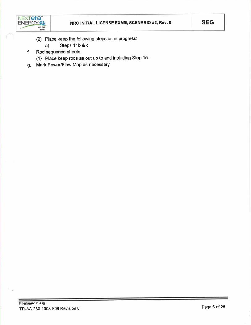
(2) Place keep the following steps as in progress:
a) Steps 1 1b & c
f. Rod sequence sheets
(1) Place keep rods as out up to and including Step 15'
g. Mark Power/Flow Map as necessary
Filename:2_esg
TR-AA-230-1 003-F06 Revision 0 Page 6 of 25
SEGNRC lNlTlAL LICENSE EXAM, SCENARIO #2, Rev.0NEXTETA-
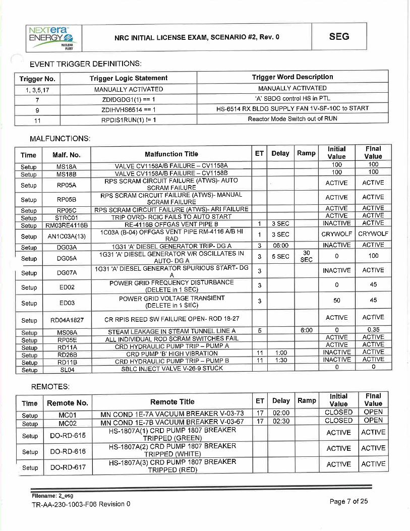
=Yær6EVENT TRIGGER DEFINITIONS
Reactor Mode Switch out of RUNRPDISIRUN(1) l= 111
HS-6514 RX BLDG SUPPLY FAN 1V-SF-10C to STARTZDlHVHS6514 == 1o
'A' SBDG control HS in PTLZDIDGDGI(1) == I7
MANUALLY ACTIVATEDMANUALLY ACTIVATED1,3,5,17
Trigger Word DescriptionTrigger Logic StatementTrigger No.
MALFUNCTIONS
00SBLC INJECT VALVE V-26-9 STUCKSLO4Setuo
ACTIVEINACTIVE1:3011RD HYDRAU MP TRIP - PUMPRD11BSetup
ACTIVEINACTIVE1:0011CRD PUMP'B' HIGH VI BRATIONRD26B
ACTIVEACTIVECRD HYD MP TRIP - PUMPRD11ASetup
ACTIVEACTIVEALL INDIVIDUAL ROD SC RAM SWITCHES FAILRPOsES
0.3506:005STEAM IN STEAM TUNNE AMSOSA
ACTIVEACTIVECR RPIS REED SW FAILURE OPEN- ROD 18-27RD0441827Setup
45503POWER GRID VOLTAGE TRANSIENT(DELETE in 1 SEC)EDO3Setup
4503POWER GRID FREQUENCY DISTURBANCE(DELETE in 1 SEC)EDO2Setup
ACTIVEINACTIVE31G31 'A' DIESEL GENERATOR SPURIOUS START- DGADGOTA
100030
SEC5 SEC31G31 'A'DIESEL GENERATOR V/R OSCILLATES INAUTO-DGOSA
ACTIVEINACTIVE06:0031G31 'A'D GENERATOR TRIP- ADGO3ASetuo
CRWVOLFCRWVOLF3 SEC11C034 (B-04) OFFGAS VENT PIPE RM-4116 A/B HI
AN1C03A(13)Setup
ACTIVEINACTIVE3 SEC1RE-41168 OFFGAS VENT PIPE BRMO3RE41 168Setup
ACTIVEACTIVETRIP OVRD- RCIC FAILS TO AUTO STARTSTRCOlSetuo
ACTIVEACTIVETWS)- ARI FAILURERPS SCRAM CIRCUIT FAILURE (ARPOSCSetup
ACTIVEACTIVERPS SCRAM CIRCUIT FAILURE (ATWS)- MANUALSC FAILURERPOSBSetup
ACTIVEACTIVERPS SCRAM CIRCUIT FAILURE (ATWS)- AUTOSCRAM FAILURERPOSASetup
100100LVE CV1158A/B FAI - cv1 1588MS18B
100100VALVE CV1158A/B FAILURE - CV1158AMS18ASetup
FinalValue
lnitialValueRampDelayETMalfunction TitleMalf. NoTime
Setup
Setup
REMOTES:
ACTIVEACTIVEHS-18074(3) CRD PUMP 1807TRIPPED (RED)
BREAKERDO-RD-617
ACTIVEACTIVEHS-1807A(2) CRD PU MP 1807 BREAKERTRIPPEDDO-RD-616Setup
ACTIVEACTIVEHS-1807A(1)CRD PUMP 1 807 BREAKERTRIPPED GRDO-RD-615Setup
OPENCLOSED02:3017M N coN D I E-7B VAC U U M BR EAKER V-03-67MC02Setup
OPENCLOSED02:0017MN coN D 1 E-7A VAC U U M BREAKE R V-03-73MC01Setup
FinalValue
lnitialValueRampDelayETRemote TitleRemote No.Time
Setup
PageT of25Filename: 2_esg
TR-AA-230-1003-F06 Revision 0

SEGNRC lNlTlAL LICENSE EXAM, SCENARIO #2, Rev.0NEXTETA-
=Yæ"&SCHEDULE FILES
Modifv malfunction msO8a to 0.6 in 300I1G31 'A' DIESEL GENERATOR TRIP- DG ADelete malfunction dg03a7Setup
DescriActionEvent@ TimeActions.sch
Conduct simulator crew pre-scenario brief using TR-AA--230-1007-F06, Simulator lnstructorPre-Exercise Checklist.
lf surrogate operators are to be used, brief them using TR-AA-230-1007-F11, Surrogate Brief
Checklist
Filename:2-esg
TR-AA-230-1 003-F06 Revision 0 Page I of 25
SHIFT TURNOVER INFORMATION
SEGNRC lNlTlAL LICENSE EXAM, SCENARIO #2, Rev.0NEXTETA'EYæx6:t
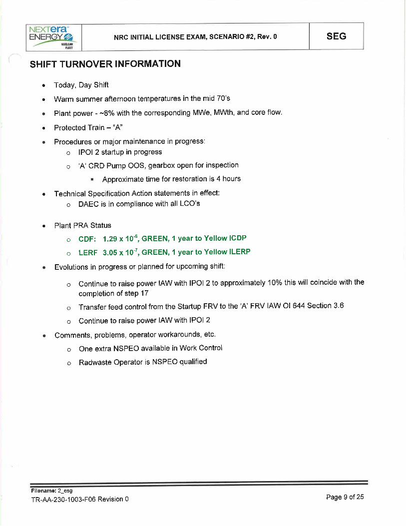
o Today, Day Shift
o Warm summer afternoon temperatures in the mid 70's
. Plant power - -8o/o with the corresponding MWe, MWth, and core flow
o Protected Train - "4"
o Procedures or major maintenance in progress:
o lPOl 2 startup in Progress
o 'A'CRD Pump OOS, gearbox open for inspection
' Approximate time for restoration is 4 hours
. Technical Specification Action statements in effect:
o DAEC is in compliance with all LCO's
a Plant PRA Status
o CDF: 1.29 x 10⁻⁶, GREEN, I year to Yellow ICDP
o LERF 3.05 x 10⁻⁷, GREEN, 1 year to Yellow ILERP
Evolutions in progress or planned for upcoming shift:
o Continue to raise power IAW with lPOl 2 to approximately 10% this will coincide with the
completion of steP 17
o Transfer feed control from the Startup FRV to the 'A' FRV IAW Ol 644 Section 3.6
o Continue to raise power IAW with lPOl 2
Comments, problems, operator workarounds, etc'
o One extra NSPEO available in Work Control
o Radwaste Operator is NSPEO qualified
O
a
Filename:2_esg
TR-AA-230-1 003-F06 Revision 0 Page 9 of 25

NE)CìETA'
=Yærç NRC INITIAL LICENSE EXAM, SCENARIO #2, Rev.0 SEG
rPot 2
TIME/NOTES
SIMULATOR EXERCISE GUIDE SCENARIO INSTRUCTIONSINSTRUCTOR ACTIVITY
CREWa Withdraw control rods IAW lPOl 2 and Ol 856.1 to complete step 17
ROa When reactor power reaches approximately 10% power on APRMs
or as desired by the CRS/OSMContinue to raise power with control rod withdrawal until one bypassvalve is open and the second bypass valve is approximately 25o/o
open.
o Monitor neutron monitoring instrumentation during control rodmovements.
o Verifies the following indications:o White backlight on the Rod Select pushbutton turns ON
. On the Full Core Display, the white .XX-XX' select lightcorresponding to the rod selected turns ON
. On the Four Rod Group Display, the white SELECT lightturns ON denoting the position display for the selectedrod.
o
EXPECTED STUDENT RESPONSE
Filename: 2_esg
TR-AA-230-1 003-F06 Revision 0 Page 10 of25

NEXTETA
=ysre_ NRC lNlTlAL LICENSE EXAM, SCENARIO #2, Rev.0 SEG
Raise PowerCont.
TIME/NOTES
SIMULATOR EXERCISE GUIDE SCENARIO INSTRUCTIONSINSTRUCTOR ACTIVITY
RO
Momentarily places the ROD MOVEMENT CONTROL in theOUT-NOTCH position and verifies:
. The green ROD lN light turns ON momentarily and thenturns OFF
. The red ROD OUT light turns ON after the green ROD lNlight turns OFF.
¡ The red ROD OUT light turns OFF
. The amber ROD SETTLE light turns ON and then turnsOFF
. The rod has been withdrawn as indicated on the Four RodGroup Display
CRSa Direct and observe reactivity manipulations to achieve step 17
complete
EXPECTED STUDENT RESPONSE
Filename: 2_esg
TR-AA-230-1 003-F06 Revision 0 Page 11 ot25

NÐCIETA'NRC lNlT¡AL LICENSE EXAM, SCENARIO #2, Rev.0 SEG
Shift FRVfromS/U to'A'o1644
TIME/NOTES
SIMULATOR EXERCISE GUIDE SCENARIO INSTRUCTIONS
Booth CommunicatorAcknowledge coordi nation
INSTRUCTOR ACTIVITYCREW
RO
CRSa
a Shift FRV from the S/U FRV to the 'A' FRV
o Shift feed flow control from the STARTUP FEED REG VALVE to AFEED REG VALVE as follows:
o Verify the MASTER FEED REG VALVE CONTROLLER, LC-4577, is in AUTO and select 'V'with the D pushbutton on thedisplay.
o Verify the STARTUP FEED REG VALVE CONTROLLER,HC-1622, is in AUTO.
o Verify the A FEED REG VALVE CONTROLLER HC-1579 isin MANUAL.
o Select'V' on the display for the A FEED REG VALVECONTROLLER, HC-1579.
o Slowly open A FEED REG VALVE CV-1579 using thepotentiometer on HG-1 579.
o Monitor reactor water level closely and confirm auto operationof FEEDWATER STARTUP FEED REG VALVECV-1622.
o When the display on CV-1579 is matching the display on LC-4577, select AUTO on HC-1579.
o Select MANUAL on STARTUP FEED REG VALVECONTROLLER HC-1622.
o Slowly close STARTUP FEED REG VALVECV-1622 usingthe potentiometer on HC-1622.
o Monitor reactor water level closely and verify auto operationof A FEED REG VALVE CV-1579.
o Close MO-1631, Startup Feedline Block.
Coordinate shifting feed flow controlfrom the STARTUP FEED REGVALVE to A FEED REG VALVE.
EXPECTED STUDENT RESPONSE
Filename: 2_esg
TR-AA-230-1 003-F06 Revision 0 Page 12 of 25

NEXI ETA-NRC lNlTlAL LICENSE EXAM, SCENARIO #2, Rev.0 SEG
Control RodPosition LostAOP 255.1
lF called as anyDAEC supportpersonnel:
lf contacted asRE forsubstitutingposition for rod18-27:
Two minutesafter contactedas RE:
TIME/NOTES
SIMULATOR EXERCISE GUIDE SCENARIO INSTRUCTIONS
Booth GommunicatorAcknowledge coordination
Booth GommunicatorAcknowledge commu nication
Booth GommunicatorReport to the control room that you
concur with substituting rod positionfor rod 18-27 and to continue with
startup.
INSTRUGTOR ACTIVITYCREW
Perform the Follow Up Actions of AOP 255.1 for Abnormal RodControl and Position lndications
For rod position indication lost at one notch:o Attempt to move the affected rod, as allowed by rod
sequence, to an adjacent notch to check for reed switchfailure
o Consult with CRS/OSM and Reactor Engineer to modify rodpattern if necessary to avoid leaving the control rod at thenotch with no position indication
Direct the performance of AOP 255.1 forAbnormal Rod Control andPosition lndicationsConsult with Reactor Engineer to enter Substitute Rod Position into3D Monicore per REDPT Section 3.7, Substituting Rod Positions ln3D Monicore.
a
ROa
CRSa
a
EXPECTED STUDENT RESPONSE
Filename: 2_esg
TR-AA-230-1 003-F06 Revision 0 Page 13 of 25

=YtsgNEXTETA'
NRC lNlTlAL LICENSE EXAM, SCENARIO #2, Rev.0 SEG
PositionSubstitution878.8
TIME/NOTES
SIMULATOR EXERCISE GUIDE SCENARIO INSTRUCTIONS
INSTRUCTOR ACTIVITYCREW
a Substitute notch position IAW Ol 878.8 Section 8.2RO
. At 1C28, verify the Rod Worth Minimizer (RWM-CC) keylock MODEswitch in the OPER position.
. At 1C05, verify the Rod Worth Minimizer (RWM-OD) keylock modeswitch is in the OPERATE position.
. At 1C05 (RWM-OD), press the ETC soft-key untilthe SUBSTITUTEOPTIONS menu choice becomes available.
o Press the appropriate soft-key.o Press the INCREMENT POS¡TION soft-key to select the desired
position.. lndependently verify desired position on RWM Display¡ Press the ENTER SUBSTITUTE soft-key.. Verify screen display.o Press the EXIT soft-key. lnsert rod 18-27 to position 06
CRSa
a
Direct substituting notch position for rod 18-27Direct rod 18-27 insertion to n06
EXPECTED STUDENT RESPONSË
Filename: 2_esg
TR-AA-230-1 003-F06 Revision 0 Page 14 of 25
NEXTETA"
=Yæ4 NRC INITIAL LICENSE EXAM, SCENARIO #2, Rev.0 SEG
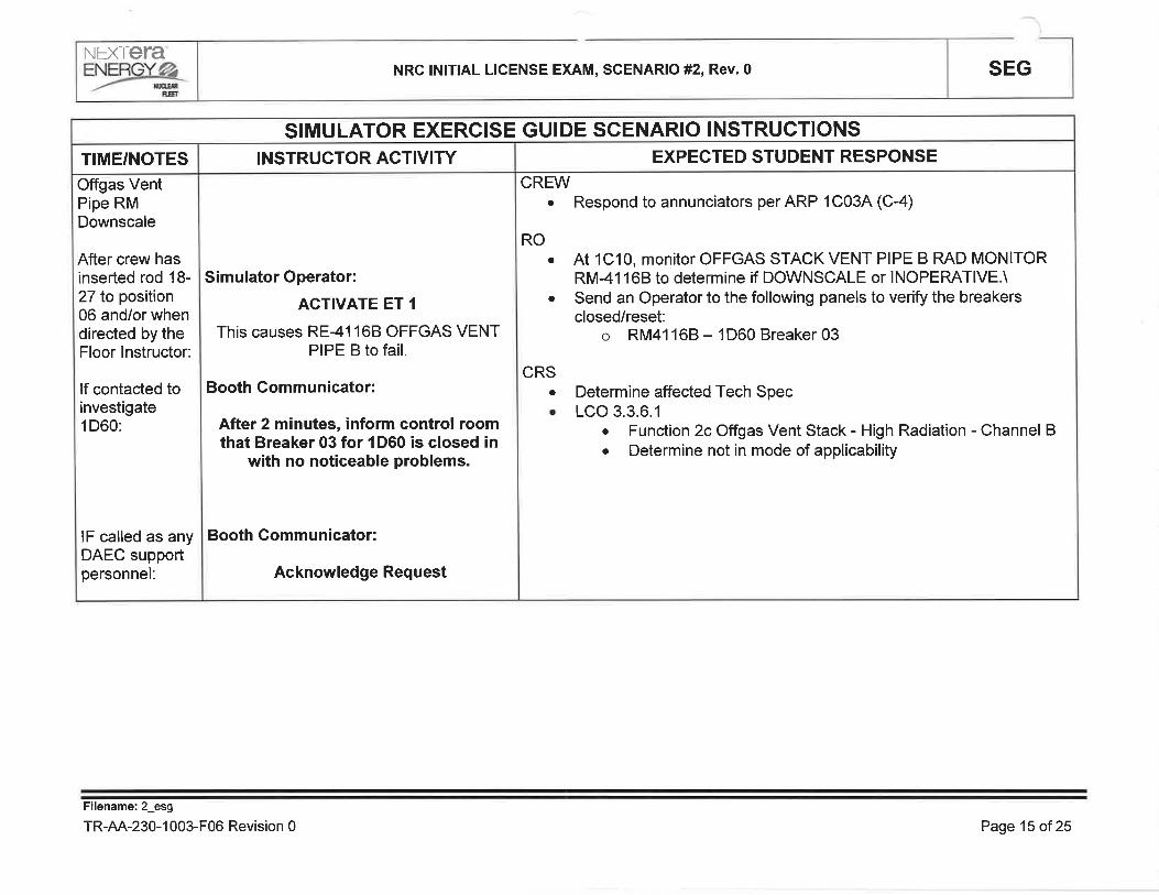
Offgas VentPipe RMDownscale
After crew hasinserted rod 18-27 to position06 and/or whendirected by theFloor lnstructor:
lf contacted toinvestigate1 D60:
lF called as anyDAEC supportpersonnel:
TIME/NOTES
SIMULATOR EXERCISE GUIDE SCENARIO INSTRUCTIONS
Simulator Operator:
ACTIVATE ET 1
This causes RE-41168 OFFGAS VENTPIPE B to fail.
Booth Communicator:
After 2 minutes, inform control roomthat Breaker 03 for 1D60 is closed in
with no noticeable problems.
Booth Gommunicator:
Acknowledge Request
INSTRUCTOR ACTIVITYCREW
a Respond to annunciators per ARP 1C034 (C-4)
ROa At 1C10, monitor OFFGAS STACK VENT PIPE B RAD MONITOR
RM-41168 to determine if DOWNSCALE or INOPERATIVE.\Send an Operator to the following panels to verify the breakersclosed/reset:
o RM41168 - 1D60 Breaker 03
a
CRS. Determine affected Tech Spec. LCO 3.3.6.1
o Function 2c Offgas Vent Stack - High Radiation - Channel Bo Determine not in mode of applicability
EXPECTED STUDENT RESPONSÉ
Filename: 2_esg
TR-AA-230-1 003-F06 Revision 0 Page 15 of25

NEX refa'NRC lNlTlAL LICENSE EXAM, SCENARIO #2, Rev.0 SEG
When directedby the Floorlnstructor:
lF called as anyDAEC supportpersonnel:
lf contacted toinvestigate'A'SBDG:
Three minutesafter requestedto investigate.A'SBDG:
lf contacted toverify operationof 'A' ESW:
Two minutesafter requestedto verifyoperation'A'ESW:
TIME/NOTES
SIMULATOR EXERCISE GUIDE SCENARIO INSTRUCTIONS
Simulator Operator:
ACTIVATE ET 3
This causes a momentary griddisturbance. 'A' SBDG will spuriously start
and its voltage regulator fail.
Booth Gommunicator:
Acknowledge Request
Booth Gommunicator:
Acknowledge Request
Booth Gommunicator:
Inform control room that'A'SBDGappears to be normal and all alarms at
1C93 are as expected.
Booth Gommunicator:
Acknowledge Request
Booth Gommunicator:
lnform control room that'A' ESW isoperating SAT.
INSTRUCTOR ACTIVITYCREW
a Respond to annunciators perARP 1C084 (A-10)RO
. Verify that EMERG SERV WATER PUMP 1P-994 is running.o Verify 1V-SF-20 Diesel Generator Supply Fan is running.
. lf "4" SBDG 1G-31 was not started for testing and is no longerrequired for operation, shut down '4" SBDG 1G-31 per O1324(Standby Diesel Generator System).
CRSa ¡f SBDG 1G-31 is determined to be inoperative, comply with the
Technical Specification requirements for AC Sources-Operating andAC Sources-Shutdown.
EXPECTED STUDENT RESPONSE
Filename:2_esg
TR-AA-230-1 003-F06 Revision 0 Page 16 of25

NEXTETA'
=ysre_ NRC lNlTlAL LICENSE EXAM, SCENARIO #2, Rev.0 SEG
When the crewplaces the 'A'SBDG in PTL:
lf the crewrequests a copyofsTP 3.8.1-01and/or STP3.8.1-02:
TIME/NOTES
SIMULATOR EXERCISE GUIDE SCENARIO INSTRUCTIONS
Simulator Operator:
VERIFY ET 7 ACTIVATES
This deletes malfunction dg03a.
Simulator Operator:lf the crew does not take the 'A' SBDG
to PTL prior to the auto trip:
Pause "Delete malfunction dg03a" inActions.sch
AND
INSERT ET 7
Evaluator Note:lf the crew does not place 'A' SBDG in
PTL in 6 minutes, it will trip on generatorlockout.
Floor Evaluator:Give the crew the requested copy of
STP 3.8.1-01 and/or STP 3.8.1-02
INSTRUCTOR ACTIVITY
Determine that'A' SBDG is not operating correctly and secure it byplacing the handswitch HS-32314 in PTL.
a Place'A'SBDG handswitch HS-32314 in PTL
Determine that the 'A' SBDG is INOPERABLE and enter appropriateTech Specs
LCO 3.8.1, Condition B
. 8.1, Perform SR 3.8.1.1 for Operable offsite circuits within 1
hour AND once per 12 hours thereafter.
. 8.2 Declare required features, supported by the inoperable DGinoperable when the redundant required features are inoperablewithin 4 hours from discovery of Condition B concurrent withinoperability of redundant required feature(s).
o 8.3 Determine OPERABLE DG is not inoperable due to commoncause failure within 24 hrs.
o 8.4 Perform SR 3.8.1.2 for OPERABLE DG once per 72hrs.. 8.5 Restore DG to OPERABLE Status within 7 days.
CREW
RO
CRSa
a
a
EXPECTED STUDENT RESPONSE
Filename: 2_esg
TR-AA-230-1 003-F06 Revision 0 Page17 of25

NEX rCfa'
YPYK NRC lNlTlAL L¡CENSE EXAM, SCENARIO #2, Rev.0 SEG
TIME/NOTES
EOP 3
Steam Leak inSteam Tunnel
After SBDG hasTS has beendeclared and atthe direction ofthe Floorlnstructor:
INSTRUCTOR ACTIVITY
Simulator Operator:
ACTIVATE ET 5
This will insert MS08A to start the SteamTunnelsteam leak.
(NOTE: Bring up EOPSLD and monitorSteam Tunnel Temperature)
SIMULATOR EXERCISE GUIDE SCENARIO INSTRUCTIONSEXPECTED STUDENT RESPONSE
CREW
Respond to annunciators perARP 1C048 (B-4), STEAM LEAK DETAMBIENT HITEMP/EOP 3.
Send an Operator to 1C21to determine which area has the hightemperature condition.
Start 1V-EF-1,1V-EF-Z and 1V-EF-3 MAIN PLANT EXHAUSTFANS by positioning the following handswitches to START and verifytheir respective dampers indicate OPEN:
o Fan Handswitch Panel Damper
o 1V-EF-1 HS-7613 1C234 1V-AD-16U
o 1V-EF-2 HS-7614 1C238 1V-AD-16V
o 1V-EF-3 HS-7615 1C23C 1V-AD-16W
o Start the Reactor Building Exhaust Fans by positioning thefollowing handswitches to START:
o Fan Handswitch Panel
o 1V-EF-114 HS-76114 1C23A.
o 1V-EF-118 HS-76118 1C238
o Start the Reactor Building Supply Fans by positioning thefollowing handswitches to START:
o Fan Handswitch Panel
o 1V-SF-104 HS-6512 1C23Ê.
o 1V-SF-108 HS-6513 1C238
o 1V-SF-10C HS-6514 1C23C
lnsert manual reactor scram
RO
a
a
a
a
Filename: 2_esg
TR-AA-230-1 003-F06 Revision 0 Page 18 of 25

NÐ(Tera-NRC INITIAL LIGENSE EXAM, SGENARIO #2, Rev.0 SEG
EOP 1
Transition toATWS
EOP 3 Cont.
TIME/NOTES
SIMULATOR EXERCISE GUIDE SCENARIO INSTRUCTIONSINSTRUCTOR ACTIVITY
CREWa lmplements the mitigation strategies of EOP 1 and EOP ATWS
ROo lnserts a manual reactor scram.. Reports the'B' CRD pump high vibes and tripo Recognizes an electricalATWS has occurred and reports the type of
ATWS and reactor power.. Places the master Feedwater level controller to 158.5" in AUTO.
CRSo Enters EOP 1, RPV Control based on reactor power is above 5o/o or
unknown after a scram signal is received.. Determines that a reactor scram has been initiated. Validates isolations, initiations and SBDG initiations that should have
occurred but did not.o Recognizes and implements the CRS "IF any rod is withdrawn past
position AND it has NOT been determined that the reactor will remainshutdown under all conditions without boron THEN exit thisprocedure and enter ATWS".
CRS
a Direct Crew Response for performance of EOP 3 for high areatemperatures level including EOP 1
o Direct Main Plant Supply and Exhaust Fans in a 3-2-3 lineup
o Determines RPV pressure reduction will lessen the leakagerate.
o Before steam tunnel temperature reaches the Group Isetpoint enter EOP 1 and direct inserting manual reactorscram.
EXPEGTED STUDENT RESPONSE
Filename:2_esg
TR-AA-230-1 003-F06 Revision 0 Page 19 of25

NEXTETA'NRC INITIAL LICENSE EXAM, SCENARIO #2, Rev. 0 SEG
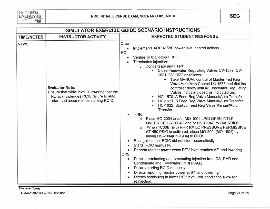
ATWS
lf directed tovent the scramair header:
Three (3)minutes afterbeing directedto vent thescram airheader:
TIME/NOTES
S¡MULATOR EXERCISE GUIDE SCENARIO INSTRUCTIONS
Booth Gommunicator:Acknowledge the request.
Booth Gommunicator:lnform the control room that you
cannot vent the scram air header due tothe valve being bound.
INSTRUCTOR ACTIVITY
Crewa lmplements the mitigation strategies of EOP 1 and EOP ATWS
RO. Locks out ADS (CRITICAL). Performs the ATWS QRC.. Reports completion of the ATWS QRC. Determines that ARI was
unsuccessful. Reports RPV level and reactor power.. Announces failure to scram.. Reports SBLC inject pressure high and no flow.o lnstalls Defeat 11.
¡ Directs locking out ADS.o Verifies at least one set of inboard and outboard MSIVs are not open.. Directs performance of the ATWS QRC.o Directs initiation of SBLC.o Directs electricalATWS rod insertion procedures. Exits the ATWS "Q" leg flowpath and enters "L" leg actions
RSc
EXPECTED STUDENT RESPONSE
Filename:2_esg
TR-AA-230-l 003-F06 Revision 0 Page 20 of 25
NEXTETA
=Yærç NRC lNlT¡AL LICENSE EXAM, SCENARIO #2, Rev.0 SEG
ATWS
TIME/NOTES
SIMULATOR EXERCISE GUIDE SCENARIO INSTRUCTIONS
Evaluator Note:Ensure that while level is lowering that the
RO acknowledges RCIC failure to autostart and recommends starting RCIC.
INSTRUCTOR ACTIVITY
Crewlmplements AOP ATWS power level control actions
ROo
a
a
a
Verifies or trip/lockout HPCI.Terminates injection:
o Condensate and Feed:. Close Feedwater Regulating Valves CV-1579, CV-1621'
"JJ:îrli jllij;,,."r or Master Fed RegValve Auto/Man Control LC4577 and dialthecontroller down until all Feedwater RegulatingValves indicate closed as indicated on:. HC-1579, A Feed Reg Valve Manual/Auto Transfer. HC-1621, B Feed Reg Valve Manual/Auto Transfer
. HC-1622, Startup Feed Reg Valve Manual/AutoTransfer
RHR:o Place MO-2004 and/or MO-1904 LPC¡ OPEN INTLK
OVERRIDE HS-2004C and/or HS-1904C to OVERRIDEo When 1C038 (B-5) RHR RX LO PRESSURE PERMISSIVE
AT 450 PSIG is activated, close MO-2004[MO-190a] bytaking HS-2004[HS-1 904] to CLOSE
Recognizes that RCIC did not start automaticallyStarts RCIC manually.Reports reactor power when RPV level reaches 87" and lowering.
. Directs terminating and preventing injection from CS, RHR andCondensate and Feedwater. (CRITICAL)
. Directs starting RCIC manually
. Directs reporting reactor power at 87" and lowering.
. Directs continuing to lower RPV level until conditions allow forreinjection.
o
a
a
CRS
EXPECTED STUDENT RESPONSE
Filename: 2_esg
TR-AA-230-1 003-F06 Revision 0 Page21 of25

NEX refa'eNTljYø_
nnr R
NRC lNlTlAL LICENSE EXAM, SCENARIO #2, Rev.0 SEGRET
When all rodsare full in:
lF directed tobreak MainCondenserVacuum:
ATWS
TIME/NOTES
SIMULATOR EXERCISE GUIDE SCENARIO INSTRUCTIONS
Simulator Operator:
Acknowledge the direction, then
ACTIVATE ET 17
This inserts remote functions mc01 andmc02.
INSTRUCTOR ACTIVITY
Crewa When all rods are in, transition from ATWS to EOP 1
ROa Reports rod insertion working by drifting rods, and/or removing RPS
Fuses. (CRITICAL)Controls level 170"-211" using Condensate and Feedwater(cRrTrcAL)
a
cRS. Directs transition back to EOP 1
. Directs RPV level 170"-211" using Condensate and Feedwater
EXPECTED STUDENT RESPONSE
Filename: 2_esg
TR-AA-230-1 003-F06 Revision 0 Page22 of 25
NEXTETA"ENERGYØ
ffi
NRC lNlTlAL LICENSE EXAM, SCENARIO #2, Rev.0
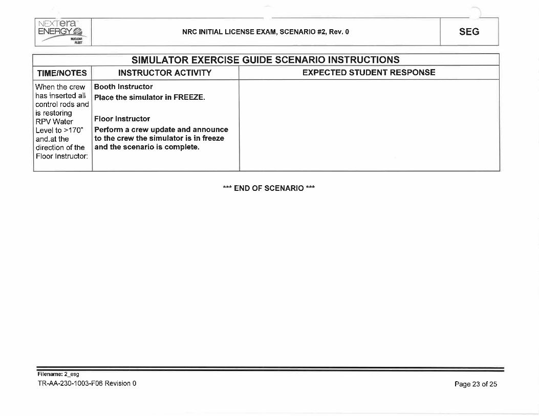
**" END OF SCENARIO ***
SEG
When the crewhas inserted allcontrol rods andis restoringRPV WaterLevelto >170"and.at thedirection of theFloor lnstructor:
TIME/NOTES
SIMULATOR EXERCISE GUIDE SCENARIO INSTRUCTIONS
Booth InstructorPlace the simulator in FREEZE.
Floor lnstructorPerform a crew update and announceto the crew the simulator is in freezeand the scenario is complete.
INSTRUCTOR ACTIVITY EXPECTED STUDENT RESPONSE
Filename: 2_esg
TR-AA-230-1 003-F06 Revision 0 Page 23 of 25

.l
SEGNRC |N¡TIAL LICENSE EXAM, SCENARIO #2, Rev. 0NEXIETA"eW
QUANTITATIVE ATTRI BUTES
Malfunctions:
Before EOP Entry:
1. Loss of notch indication
2. RE-41168 Offgas Vent Pipe "8" Failed Downscale
3. .A" SBDG 1G-2l Spurious Start and failure to maintain Voltage Regulation
After EOP Entry:
1. RCIC Fails to Auto Start
Abnormal Events:
1. AOP 255.1
2. ARP 1CO8A
Maior Transients:
1. EOP 3 Steam Tunnel Leak
2. ElectricalATWS
Critical Task
1. li4: lF a scram is required and reactor power is above 5%, THEN reduce power below 5%
using one or more of the following methods: {BWROG RPV 4' 1, 5'1, 6'1}
lnserting control rods using RlPs
2. #6: lF a reactor scram is required and the reactor is not shutdown under all conditions,THEN lockout ADS before automatic actuation. {BWROG RPV 4.2,5.2,6.21
3. #10: lF a reactor scram is required, and reactor power is >5%, and Power/Level Control isrequired, THEN terminate and prevent injection until conditions allow reinjection.
{BWROG RPV 6.3}
4. #7: lF performing ATWS Power/Level Control and Conditions are met to allow reinjection,THEN crew actions are taken to maintain RPV level above -25" by injecting using Table 1B
systems. {BWROG RPV 5.5}
Filename:2_esg
TR-AA-230-1 003-F06 Revision 0 Page 24 of 25

SEGNRC lNlT¡AL LICENSE EXAM, SCENARIO #2, Rev.0NEXTETA",Yæ,&
CREW GRADING ATTACHMENT
ESG 2 Rev. __ !_ Date
B.O.P
1C03
1C05
STA
CRS
OSM
EvaluatorPositionOperator Name
Management Representative/Lead Evaluator
Crew Critical Tasks
I
4. lF performing ATWS Power/Level Control and Conditions are met toallow reinjection, THEN crew actions are taken to maintain RPV level
above -25" by injecting using Table 1B systems.
3. lF a reactor scram is required, and reactor power is >5%, andPower/Level Control is required, THEN terminate and prevent injectionuntil conditions allow reinjection.
2. lF a reactor scram is required and the reactor is not shutdown under all
conditions, THEN lockout ADS before automatic actuation. (Potential)
1. lF a scram is required and reactor power is above 5%, THEN reducepower below 5% using one or more of the following methods:
. lnserting control rods using RlPs
UNSATSATTask Statement
Fílename:2_esg
TR-AA-230-1 003-F06 Revision 0 Page 25 ol 25

STP
Page
Rev.
1of 1
5
3.8.1-0 1
1
SURVEILLANCE TEST PROCEDURE
TITLE: OFFSITE POWER SOURCESDAE,CDUANE ARNOLD ENERGY CENTER
Usage Level
CONTINUOUS
Record the following: Date / Time: | _lnitialsNOTE: IJser shatt perform and document a Temp lssue / Rev. Check to ensure revision is current,
in accordance with procedure use and adherence requirements.
Prepared By: Date
Print Signature
Reviewed By: Date
Print Signature
Reviewed By: Date
Print Signature
Reviewed By: Date
Print Signature
cRoss-DlsclPLlNE REVIEW (AS REQUIRED)
Approved By I Date
Print Signature
PROCEDURE APPROVAL

STP
Page
Rev.
3.8.1-01
2of115
SURVEILLANCE TEST PROCEDURE
TITLE: OFFSITE POWER SOURCESDAECDUANE ARNOLD ENERGY CENTER
1.0
1.1
PURPOSE
This STP verifies correct breaker alignment and indicated power availability for each offsitecircuit capable of supplying the onsite Class 1E AC Electrical Distribution System.
This STP is routinely performed with both offsite circuits available, or in response to thecondition of one offsite circuit or one diesel generator inoperable.
BRIEFING INFORMATION
PERFORMANCE I NFORMATION
2.1.1 Section 7.0 of this STP contains two (2) sections that cover the anticipatedconditions under which this STP will be performed. The STP is organized as follows:
One Offsite Circuit Available7.2
Both Offsite Circuits Available7.1
ConditionsSect.
Only one of these sections should need to be performed to satisfy the performancerequirements associated with this STP. All steps within a particular section are to beperformed in sequence and the STP steps carried through to completion, unlessstated othenruise.
2.1.2 Personnel recommended to perform this procedure:
1 Operations
2.1.3 Special Test Equipment required:
1 Marking Pen (Do not use light colored hi-lighters or markers. Use only darkcolored pens or markers. See General Caution 2,2.1).
2.2 GENERAL CAUTIONS
2.2.1 lf utilizing a paper copy of this surveillance, do not use light colored hi-lighters ormarkers to record data, outline configurations on drawings or to initial steps.Light-colored hi-lighters are not dark enough to reproduce adequately as the QArecord. Not applicable when using electronic copies.
2.3 SPECIAL PRECAUTIONS
2.3.1 None
1.2
2.0
2.1

STP
Page
Rev.
3.8.1-01
3 of 11
5
SURVEILLANCE TEST PROCEDURE
TITLE: OFFSITE POWER SOURCESDAECDUANE ARNOLD ENERGY CENTER
3.0
3.1
3.2
4.0
4.1
4.2
4.3
REFERENCES
Applicable drawings:
3.1.1 BECH-E001<1>
3.1.2 BECH-E005
3.1.3 BECH-E023
Supporting documents:
3.2.1 NG-97-2146
GENERAL INSTRUCTIONS
Steps marked with a "TS" immediately to the right of the step sign-off line are required by
Technical Specifications. lf these steps do not meet their acceptance criteria or cannot beperformed, a NRC reportable condition may exist and shall be reported to the Control Room
Supervisor (CRS) immediately.
lf any equipment or components are observed to be in a state of disrepair during theperformance of this STP, appropriate corrective maintenance shall be initiated.
An Action Request (AR) should be completed for any problems encountered with "TS" markedsteps during the performance of this test.
The CRS shall be notified immediately and the appropriate Limiting Conditions for Operationsection of Technical Specifications referred to whenever problems are encountered during theperformance of this STP.
4.4
5.0 APPENDICES
None
INITIALSPerformance Date:Prerequisites
STP
Page
Rev.
3.8.1-01
4of115
SURVEILLANCE TEST PROCEDURE
TITLE: OFFSITE POWER SOURCESDAECDUANE ARNOLD ENERGY CENTER
6.0
6.1
6.2
PREREQUISITES
Verify Offsite power is supplying essential buses 143 and 1A4 via either thestartup transformer (normal source) or the standby transformer (alternatesource).
Evaluate electrical system status and select the STP section which is to beperformed:
t I Section 7.1 - Both Offsite Circuits Available
t 1 Section 7.2 - One Offsite Circuit Available

INITIALSPerformance Date
STP
Page
Rev.
3.8.1-01
5 of 11
5
SURVEILLANCE TEST PROCEDURE
TITLE: OFFSITE POWER SOURCESDAECDUANE ARNOLD ENERGY CENTER
7.0
7.1
PROCEDURE
BOTH OFFSITE CIRCUITS AVAILABLE
NOTE
lnformation from the Load Dispatcher may be needed to complete the followingstep.
7.1.1 Using the guidance below and Attachment 1, identify twoseparate circuits available to transmit power from the offsitepower sources to the essential buses.
a. Based on equipmenVsystem lineup and operational status,use a dark marking pen to trace an available circuit from anoffsite power source to the Startup Transformer supplybreakers, 1A302 and 14402.
b. Based on equipmenVsystem lineup and operational status,use a dark marking pen to trace a second circuit from anotheroffsite power source to the Standby Transformer supplybreakers, 1A301 and 14401 such that it does not share anylines, buses, or transformers in common with the circuit to theStartup Transformer supply breakers.
c. Based on equipmenVsystem lineup and operational status,complete the electrical lineup by using a dark marking pen totrace the connections from each Essential Bus (143 and 'tA4)
to the Startup or Standby Transformer supply breakercurrently feeding the bus.
7.1.2 Confirm two (2) independent offsite circuits are available byinitialing one of the two sets of statements below and N/A'ing theother:
a. A circuit exists from an offsite power source, through theStartup Transformer and its supply breakers to both 143 and1A4 essential buses;
AND
A second independent circuit exists from a different offsitesource, through the Standby Transformer to its supplybreakers.
TS

INITIALSPerformance Date
STP
Page
Rev.
3.8.1-01
6 of 11
5
SURVEILLANCE TEST PROCEDURE
TITLE: OFFSITE POWER SOURCESDAECDUANE ARNOLD ENERGY CENTER
b. A circuit exists from an offsite power source, through theStartup Transformer and one of its supply breakers to eitherthe 1A3 or 1A4 essential bus;
AND
A second independent circuit exists from a different offsitesource, through the Standby Transformer and one of itssupply breakers to the other essential bus.
(PRTNT / SrGN)
TS
I
I
IPerformed by: Date: Time: lnit

INITIALSPerformance Date
STP
Page
Rev.
3.8.1-01
7of115
SURVEILLANCE TEST PROCEDURE
TITLE: OFFSITE POWER SOURCESDAE,CDUANE ARNOLD ENERGY CENTER
7.2 ONE OFFSITE CIRCUIT AVAILABLE
NOTElnformation from the Load Dispatcher may be needed to complete the followingstep.
7.2.1 Using the guidance below and Attachment 1, identify a circuitavailable to transmit power from an offsite power source to theessential buses.
a. Based on equipmenVsystem lineup and operational status,use a dark marking pen to trace an available circuit from anoffsite power source to the Startup Transformer supplybreakers, 14302 and 1A402 or Standby Transformer supplybreakers, 14301 and 14401.
b. Based on equipmenUsystem lineup and operationalstatus,complete the electrical lineup by using a dark marking pen totrace the connections from the required Essential Bus(es)(143 and/or 1A4) to the Startup or Standby Transformersupply breakers.
7.2.2 lf in Mode 1,2 or 3, mark Step 7.2.4 "N/A" and proceed with theperformance of Step 7.2.3.
7.2.3
OR
lf in Mode 4 or 5, or during movement of irradiated fuelassemblies in the Secondary Containment, mark Step 7.2.3 "N/4"and proceed with the performance of Step 7.2.4.
Confirm an offsite circuit exists from an offsite power source,through either the Startup or Standby Transformer and itsassociated supply breakers to both 1A3 and 144 essential buses.
TS

INITIALSPerformance Date:
STP
Page
Rev.
3.8.1-01
I of 11
5
SURVEILLANCE TEST PROCEDURE
TITLE: OFFSITE POWER SOURCESDAE,CDUANE ARNOLD ENERGY CENTER
7.2.4 Confirm an offsite circuit exists from an offsite power source byinitialing one of the two statements below and "N/A'ing" the other:
a. An offsite circuit exists from an offsite power source, througheither the Startup or Standby Transformer and its associatedsupply breakers to both 1A3 and 144 essential buses.
b. An offsite circuit exists from an offsite power source, througheither the Startup or Standby Transformer and one of itsassociated supply breakers to the required lA3 or 144essential bus.
(PRTNT / SrGN)
I
TS
TS
I
IPerformed by: Date Time: lnit.

INITIALSPerformance Date:
STP
Page
Rev.
3.8.1-01
9 of 1l5
SURVEILLANCE TEST PROCEDURE
TITLE: OFFSITE POWER SOURCESDAECDUANE ARNOLD ENERGY CENTER
8.0
8.1
8.2
8.3
ACCEPTANCE CR¡TERIA
lndicate the reason for performing the STP:
t I Routine with both offsite circuits available
t I Routine with one offsite circuit available while in Mode 4 or 5 orduring movement of irradiated fuel assemblies in the secondarycontainment
t I Action in response to one offsite circuit inoperable
t I Action in response to one diesel generator inoperable
t I Other, explain below:
All Technical Specification required items, as indicated by "TS", have beenperformed satisfactorily:
8.2.1 Section 7.1 ( ) YES ( ) NO + CRS notified
8.2.2 Section 7.2 ( ) YES ( ) NO + CRS notified
All other items checked in this test have been performed satisfactorily:
8.3.1 Section 7.1 ( ) YES ( ) NO = CRS notified
8.3.2 Section 7.2 ( ) YES ( ) NO + CRS notified

INITIALSPerformance Date
STP
Page
Rev.
3.8.1-01
10 of 11
5
SURVEILLANCE TEST PROCEDURE
TITLE: OFFSITE POWER SOURCESDAE,COUANE ARNOLD ENERGY CENTER
8.4 lndicate any relevant test comments below, othenruise mark this step "N/4"
(PRTNT / SrGN)
I
9.0
9,1
Operations Date
ATTACHMENTS
Attachment I - DAEC Offsite Power Circuits Feeding Essential Buses
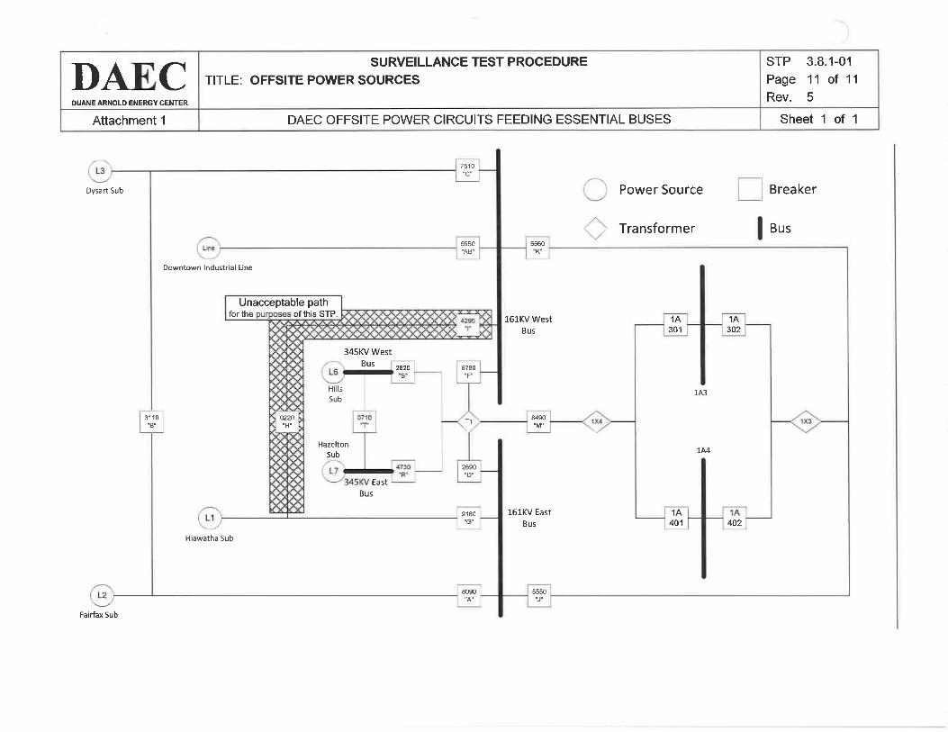
Attachment 1
DAECDUANE ARNOLD ENERGY CENTER
DAEC OFFSITE POWER C¡RCUITS FEEDING ESSENTIAL BUSES
SURVEILLANCE TEST PROCEDURE
TITLE: OFFSITE POWER SOURCES
Sheet 1 of 1
STP
Page
Rev.
3.8.1-01'11 oÍ 11
5
Dysart Sub
0220
Unacceptable pathfor the of this STP
7510
67E0
5950''AB"
8090
2690"D"
HillsSub
Sub
Hãzelton
T,I
"s"
Bus
Bus
East
345KV West
Downtown lndustriâl Line
H¡awatha Sub
31 10"8"
9180
8490
5550
1A301
1A401
1A302
402
1A3
144
"K'5560
16lKV WestBus
161KV East
Bus
Power Source
Transformer
Breaker
Bus
Fe¡rfex Sub

STP
Page
Rev.
3.8.1-021of76
SURVEILLANCE TEST PROCEDURE
TITLE ONE STANDBY DIESELGENERATOR INOPERABLE
DAE,CDUANE ARNOLD ENERGY CENTER
Usage LevelCONTINUOUS
Approved fo, þi!lg[1@] printing lF NO Temporarv Chanqes are in effect forthis procedure.
Record the following: Date / Time lnitials:
NOTE: A check to ensure current revision and no temporary changes shall be performed anddocumented every 24 hours if active document use exceeds a 24 hour period asdetermined from the date and time recorded above.
I
Prepared By: Date:
Print Signature
Approved By I Date:
Print Signature
PROCEDURE APPROVAL BY QUALIFIED REVIEWER
I
Reviewed By: I DatePrint Signature
Reviewed By I Date:
Print Signature
Reviewed By I Date:
Print Signature
cRoss-DtsctPlrNE REVTEW (AS REQUIRED)

STP
Page
Rev.
3.8.1-022o'Í 7
6
SURVEILLANCE TEST PROCEDURE
TITLE ONE STANDBY DIESELGENERATOR INOPERABLE
DAE,CDUANE ARNOLD ENERGY CENTER
1.0
1.1
1.2
2.0
2.1
2.2
2.3
3.0
3.1
PURPOSE
The purpose of this test is to implement the REQUIRED ACTIONS of LCO 3.8.1 when oneDiesel Generator is inoperable.
This procedure also provides instructions for scheduling and performance of SR 3.8.1 .1 andSR 3.8.1.2 in accordance with LCO 3.8.1 Action 8.1 and Action 8.4, respectively.
BRIEFING INFORMATION
PERFORMANCE INFORMATION
2.1.1 Testing is organized as follows:
Other Actions For One SBDG lnoperable7.2
Required Actions For LCO 3.8.1, Condition B7.1
EvolutionSTP Sections
2.1.2 Personnel recommended to perform this STP:
1 Operations
2.1.3 Special Test Equipment required:
None
GENERAL CAUTIONS
2.2.1 None
SPECIAL PRECAUTIONS
2.3,1 None
REFERENCES
Associated STPs:
3.1.1 STP 3.8.1-01
3.1.2 STP 3.8.1-03
ODI-8, LCO Surveillance Log and Flag
GENERAL INSTRUCTIONS
The Control Room Supervisor (CRS) shall be notified immediately and the appropriateLimiting Conditions for Operations section of Technical Specifications referred to wheneverproblems are encountered during the performance of this STP.
3.2
4.0
4.1

STP
Page
Rev.
3.8.1-02
3of76
SURVEILLANCE TEST PROCEDURE
TITLE ONE STANDBY DIESELGENERATOR INOPERABLE
DAECDUANE ARNOLD ENERGY CENTERo
5.0
5.1
APPENDICES
None

INITIALSPerformance DatePrerequisites
STP
Page
Rev.
3.8,1-02
4of7o
SURVEILLANCE TEST PROCEDURE
TITLE ONE STANDBY D¡ESELGENERATOR INOPERABLE
DAECDUANE ARNOLD ENERCY CENTER
6.0
6.1
PREREQUISITES
None

INITIALSPerformance Date
STP
Page
Rev.
3.8.1-025of76
SURVEILLANCE TEST PROCEDURE
TITLE ONE STANDBY DIESELGENERATOR INOPERABLE
DAECDUANE ARNOLD ENERGY CENTER
7.0
7.1
PROCEDURE
REQUIRED ACTIONS FOR LCO 3.8.1, CONDITION B
7.1.1 Enter the appropriate component designator in space providedbelow (N/A any non-applicable condition):
Diesel Generator is INOPERABLE
AND/OR
ESW Subsystem is INOPERABLE
NOTEStep 7.1.2 must be performed within one (1) hour of determining that one dieselgenerator has become inoperable.
7.1.2
7.1.3
Perform STP 3.8.1-01
Schedule performance of STP 3.8.1-01 within 1 2 hours of thecompletion of Step 7 .1 .2 in accordance with ODI-8.
NOTEln reference to the following step, initial diesel generator operability testing must beperformed within seventy-two (72) hours of declaring a diesel generator inoperableand once every 72 hours thereafter. Not required to be performed when the causeof the inoperable DG is preplanned, preventive maintenance and testing.
7 .1.4 Prepare and place LCO Surveillance Due Flags (Green Cards),requiring the performance of STP 3.8.1-03 on the operable dieselgenerator. Mark this step N/A if the cause of the inoperable DG ispreplan ned, preventive mai ntenance and testing.
NOTEStep 7.1.5 must be performed within four (4) hours of discovery that one dieselgenerator is inoperable concurrent with inoperability of redundant requiredfeature(s).
Declare required feature(s), supported by the inoperable DG,inoperable when the redundant required feature(s) are inoperable
7.1.5

INITIALSPerformance Date:
STP
Page
Rev.
3.8.1-026o'f76
SURVEILLANCE TEST PROCEDURE
TITLE ONE STANDBY DIESELGENERATOR INOPERABLE
DAE,CDUANE ARNOLD ENERGY CENTER
NOTEStep 7.1.6 must be performed within twenty-four (24) hours of determining that onediesel generator has become inoperable. Step 7.1.6 performs an evaluation todemonstrate that the remaining diesel is not susceptible to the same condition(s)that rendered the first diesel inoperable.
7.1.6 Perform an evaluation on the remaining diesel, verifying that theremaining diesel is not susceptible to the same condition(s) thatrendered the first diesel inoperable. List and describe any analysisand/or inspection(s) performed to prove continued operability ofthe remaining diesel in the spaces provided below (attachadditional sheets if necessary):
(Attach copy[ies] of supporting documents to the back of this STP)
Performed by:
7.2 OTHER ACTIONS FOR ONE SBDG INOPERABLE
7.2.'l
Date: Time
lF the associated SBDG or ESW support subsystem are/will beunavailable, THEN veriñ7 the 1K-1 Backup lnstrument AirCompressor is aligned to be powered from the operable SBDGper Ol 518.1 .
Performed by: Date Time
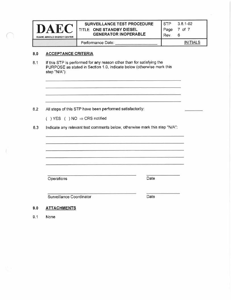
INITIALSPerformance Date:
STP
Page
Rev.
3.8.1-027 of 7
6
SURVEILLANCE TEST PROCEDURT
TITLE ONE STANDBY DIESELGENERATOR INOPERABLE
DAECDUANE ARNOLD ENERGY CENTER
8.0
8.1
8.2
8.3
9.0
9.1
ACCEPTANCE CRITERIA
lf this STP is performed for any reason other than for satisfying thePURPOSE as stated in Section 1.0, indicate below (othenruise mark thisstep "N/4"):
All steps of this STP have been performed satisfactorily:
( )YES ( )NO +CRSnotified
lndicate any relevant test comments below, othenruise mark this step "N/4":
Operations Date
Surveillance Coordinator Date
ATTACHMENTS
None

SEGSIMULATOR EXERCISE GUIDENEXTETA',Yæ1.
SITE: DAEC Revision #: 0
LMS ID: PDA OPS ESG 3 LMS Rev. Date: N/A
SEG TITLE: NRG lNlTlAL LICENSE EXAM, SCENARIO #3
SEG TYPE: n Training X Evaluation
PRocRAM: nLOCT XLOIT nOther:
DURATION: -90 minutes
Developed by:
lnstructor/Developer Date
Reviewed by:
I nstructor (l nstructional Review) Date
Validated by:
SME (Technical Review) Date
Approved by:
Training Supervision Date
Approved by:
Training Program Owner (Line) Date
Filename:3_esg
TR AA-230-1003-F06 Revision 0 Page 1 of 32

SEGNRC lNlTlAL LICENSE EXAM, SCENARIO #3 Rev. 0NEXTETA-
=Yæ6SIMULATOR EXERCISE GUIDE REQUIREMENTS
Terminal Objective This Evaluation Scenario Guide evaluates the Operators' ability to:"Given the malfunctions presented in this ESG, the students will protect thepublic, protect plant personnel, and protect plant equipment, in accordancewith plant procedures."
EnablingObjectives:
Evaluation Guide, no tasks are trained. Evaluated tasks are listed on page 4
Prerequisites: None
TrainingResources:
References:
A.B,c.D.E.F.G
SimulatorEvaluation teamOperations Management RepresentativeSimulator DriverPhone TalkerExam Proctor for custody of the crew between scenariosSimulator Video recording equipment
A. AOP 255.1, Rev. 46B. AOP 672.2, rev.37C. AOP 901, Rev. 29D. ARP 1C034, Rev.54E. ARP 1C038, rev 41
F. ARP 1C03C, rev43G. ARP 1C048, Rev. 80H. ARP 1C05A, Rev. 81l. ARP 1C058, Rev. 104
J, ARP 1C064, rev 70K. ARP 1C078, rev 89L. ED, Rev.10M, EOP 1, Rev. 19N. EOP 3 EOP 4, Rev. 21O. Ol 255, Rev. 89P. O1414. Rev.40
ProtectedContent: None
Evaluation Method: Dynamic Scenario graded in accordance with NUREG 1021 guidance
OperatingExperience:
N/A
Risk SignificantOperator Actions:
Filename:3_esg
TR-AA-230-1 003-F06 Revision 0 Page2 of 32

SEGNRC lNlTlAL LICENSE EXAM, SCENARIO #3 Rev. 0NEXTETA,YSx6
Perform internal and external notifications4.09Verifv EAL determination4.08Recommend Mitigation Strategies for Accidents Ps)4.07Direct Crew Response to Abnormal Control rod Movement/lndication5.02Direct Crew Response to Earthquake Condition5.22
Direct Crew Response for performance of EOP3 for high areatemperature/radiation/water level including EOP 1 and ED
6.67
Direct Crew Response for performance of EOP 3 for high areatemperatures/radiation /water level including commencement of a plant shutdown
6.68Direct Crew Response for performance of Emergency Depressurization6.78Direct Crew Response for performance of RC/P leg of EOP 16.46Direct Crew Response for performance of the RC/L leg of EOP 16.44Direct Crew Response for performance of initial EOP 1 actions (RC)6.45Direct Crew Response for performance of Defeat 116.21Direct Crew Response for Performance of EOP 46.72
Senior Reactor OperatorRespond to Abnormal Control rod Movement/lndication94.02Respond to Earthquake Condition94.22Perform a Fast Power Reduction93.21
Perform actions of EOP 3 for hi area temp, rad, and water level includingcommencement of plant S/D.
95.70
Manually lnsert A Scram Before Any Area Parameter Reaches Maximum SafeOperatinq Limits
95.69
Perform Actions of EOP3 for High Area Temp, Rad, Water Level lncluding EOP 1
and ED95.68
Perform an Emeroencv Depressurization Usinq SRVs95.80Perform Defeat 1195.20Perform actions of RC/P of EOP 195.46Perform actions of RC/L of EOP 195.44Perform initial EOP 1 actions (RC)95.45
Reduce Offsite Radioactivity Release Rate with a Primary System DischargingOutside of Containment
95.72Perform Actions of EOP 495.71
Reactor OperatorTask TitleTask #
TASKS ASSOCIATEÐ WITH SIMULATOR EXERCISE GUIDE
See CoverN/A
lnitial development for2017 NRC LOITExamination
lnitial development for 2017 NRCLOIT Examination
Rev.0
See CoverDATEREVIEWERAR/TWR#REASON FOR CHANGEDESCRIPTION OF CHANGE#DATEPREPARER
UPDATE LOG: lndicate in the following table any minor changes or major revisions (as defined in TR-AA-230-1003)made to the material after initial approval. Or use separate Update lna form TR-M-230-1 003-F1 6.
Page 3 of 32Filename:3_esg
TR-AA-230-1003-F06 Revision 0

NEXTETA
=Yæ6 NRC lNlTlAL LICENSE EXAM, SCENARIO #3 Rev. 0 SEG
OVERVIEW / SEQUENCE OF EVENTS
After the ED, when the crew has depressurized the RPV and is recovering RPV Waterlevel to the directed band, the scenario is complete.
8.
A steam leak will be reported from the Turbine Building. The crew will attempt to shut theMSIVs but will discover that 'A' MSIVs fail to close. This results in the crew to take actionIAW EOP 4 and perform an ED prior to reaching a GE Release Rate. (CRITICAL)
7
A steam leak develops in the RWCU room. Group 5 automatic actions failto occur,however, the leak can be isolated by closing the valves from the control room. (CRITICAL)
6.
The Crew will recognize a fuel leak and enter AOP 672.2.5
The crew will respond to a steam leak from RCIC, Enter EOP 3, and attempt to isolate theleak. The lnboard RCIC Steam Line lsolation MO-2400 will develop a thermal overload andRCIC Outboard Steam Line lsolation MO-2401 will not close; this will cause RCIC roomtemperature will exceed max normal and will approach max safe. The crew will insert a
manual reactor scram prior to temperatures exceeding max safe. (CRITICAL) After thescram, the thermal overload for MO-2400 will reset.
4
A single Control Rod scrams in during the half scram. The crew will enter AOP 255.1 and255.2 to respond to the control rod abnormal. The crew will enter Tech Spec LGO 3.1.3Control Rod OPERABILITY Gondition C.
3
Due to the OBE, PS4549, RPS ChannelA HiVessel Pressure Scram and LLS Armingswitch fails resulting in a half scram. The Crew will recognize that C71A-K5A Relay is notenergized due to a failure of PS-4549, High Reactor Pressure, relay causing an 'A' RPSAUTO SCRAM signal. The crew will enter Tech Spec LCO 3.3.1.1 RPS lnstrumentationCondition A - Function 3.
2
After alternating RBCCW pumps and power reduction an OBE Earthquake occurs and thecrew enters AOP 901.
1
Eastern lowa has the potential for severe weather. Several strong storms are forming in the Dakota'sand Western Minnesota. "4" Core Spray is out of service for replacement of the breaker overcurrentrelay. Work expected to finish tomorrow morning with operability run on days tomorrow. LCO 3.5.1
Condition B, day 2 of 7. The crew will be briefed as to the need to switch running RBCCW pumpsand lower 5o/o to assist in PPC Maintenance and HPCI testing.
DescriptionEvent #SEQUENCE OF EVENTS
Filename: 3_esg
TR-AA-230-1 003-F06 Revision 0 Page 4 of 32

SEGNRC lNlTlAL LICENSE EXAM, SCENARIO #3 Rev. 0NEXTETA"
=Yær6SIMULATOR SET UP INSTRUCTIONS
1. Set NRC Exam Security for the Simulator per QF-1071-08
2. Perform simulator set up per TDAP 1839 Attachment 2, Simulator Setup Checklist,
3. Load the saved lC (in folder with this ESG) to a SNAPSHOT reset to thatSNAPSHOT and place the Simulator in RUN, OR
4. Reset to lC 20, place the simulator in RUN and perform the following:a. lnsert Event Triggers, Malfunctions, Overrides, and Remotes per the tables below
5. COPY the Schedule Files listed below from the folder with this ESG to theS : \TRex-D u a ne\Li g htn i ng\S ched u le d i rectory.
6. RUN Schedule File "lLT3Actions,sch" and LEAVE lT RUNNING.
7. VerifyMalfunctions.8. Verify Remotes (Note that environmental remotes will already be timing)
9. Verify Overrides.
10. Startup Thundersound in Earthquake modea. At the right side instructor station computer in the booth, select THUNDERSOUND
from the Toolbar.b. Select EARTHQUAKE from the popup window.c, Toggle the red stop square to the green arrow.d. Verify the computer volume is turned up to at least 35.
1 1 . Ensure MOL pull sheet is in the 1C058 hanging file.
12. Establish EOOS conditions for OOS components and plant conditions
13. Place clearance tags on 1C03 "A' Core Spray system mimic as follows:
a. Place MIP tag on HS2103, CORE SPRAY PUMP 1P211A handswitch
b. Place a maintenance/testing border on 1C034 (A-9)
c. Make'A'Core Spray Loop UNAVAILABLE in EOOS.
d. Hang Guarded EquiPment tags on:
(1) RHR Pumps'B'&'D'(2) Core SPraY LooP'B'(3) 'B',ESW(4) 'B',SBDG
(5) 1p.4
(6) 1B,4
(7) 1844(8) 1V-AC-11
F¡lename:3_esg
TR-AA-230-1 003-F06 Revision 0 Page 5 of 32

SEGNRC lNlTlAL LICENSE EXAM, SCENARIO #3 Rev. 0NEXTETA'
=Yjçt,&
EVENT TRIGGER DEFI NITIONS:
A STEAM LINE RAD MONITORZAORMRl4448A >= .49000030
RWCU ISOLATIONcuvpmo2700 <= .05 I cuvpmo2701 <= .0528
RWCU HX Room Temperature > 130FYCASL5S >= 3026
RPV Pressure < 880RRPRV < 88024
Reactor Mode Switch out of RUNRPDISIRUN(1) != 122
21040 OUTBOARD MSIV STM LINE Amsvpcv4413 <= .9520
RX BLDG SUPPLY FNA 1V-SF-1OCyp_mms24c == 118
MANUALLY ACTIVATEDMANUALLY ACTIVATED1,3,5,7,9,12,14,16
Trigger Word DescriptionTrigger Logic StatementTrigger No.
Filename: 3_esg
TR-AA-230-1 003-F06 Revision 0 Page 6 of 32

SEGNRC lNlTlAL LICENSE EXAM, SCENARIO #3 Rev. 0NEXTCTA'
=Ysr6I MALFUNCTIONS:
îetup
Setup
ONCRYWOLF261C058 (E-08) PCIS GROUP'5' ISOLATIONINITIATEDAN1C05B(40)Setup
0.62AS IS10:0012:0028RM5945 KAMAN 2 TB NORM MONITORFAILURE (NEW)RMO9RM5945Setup
0.061AS IS5:007:OO28RM5945 KAMAN 2 TB NORM MONITORFAILURE (NEW)RMO9RM5945Setup
0.031AS IS2:304:3028RM5945 KAMAN 2 TB NORM MONITORFATLURE (NEW)RMO9RM5945Setup
0.005AS IS30SEC4:0028RM5945 KAMAN 2 TB NORM MONITOR
FAILURERM09RM5945Setup
100100MSIV DISC FAILURE- OTBD MSIV AMSO5BSetup
0024TURBINE BYPASS VALVE FAILURE- BV-2TC06BSetup
0024TURBINE BYPASS VALVE FAILURE- BV-1TC06ASetup
0.01020:0005:3030FUEL CLADDING FAILURERXOlSetup
0.5002:0004:0028MSL RUPTURE OUTSIDE PRIMARY CONTAINMENT.STM LINE AMSO4ASetup
1.5007:002:0022COOLANT LEAKAGE OUTSIDE THE PRIMARYCONTAIMENTcu10Setup
ACTIVEINACTIVE14BREAKER TRIP 1D1401 FOR MO24O1ËD228Setup
75007:0010 SEC18RCIC STEAM SUPPLY LINE BREAK (RCIC ROOM)NEWRC06
25007:001O SEC3RC|C STEAM SUPPLY LINE BREAK (RCIC ROOM)RC06
10005 SEC3RCIC ROOM COOLER ESW FLOW BLOCKAGE. 1V-AC-158SW148Setup
10005 SEC3RCIC ROOM COOLER ESW FLOW BLOCKAGE- 1V-AC-154SWl4ASetup
ACTIVEACTIVEMO24OO THERMAL OVERLOAD BREAKER TRIPRClOASetup
ACTIVEACTIVEGROUP 6 TSOLATTON VALVE(S) FAIL(S) TO CLOSE-M02401MS31BSetup
ACTIVEACTIVEGROUP 5 TSOLATTON VALVE(S) FAIL(S) TO CLOSE-MO2740M528CSetup
ACTIVEACTIVEGROUP 5 TSOLATTON VALVE(S) FAIL(S) TO CLOSE-MO2701M528BSetup
ACTIVEACTIVEcRoup 5 tsoLATroN vALVE(s) FAIL(S) TO CLOSE-M02700MS28ASetup
100100MSIV DISC FAILURE- INBD MSIV AMSOSASetup
ONON1C03A (A-09) 'A' CORE SPRAY PUMP 1P-2114 TRIPOR MOTOR OVERLOADAN1C03A(e)Setup
ACTIVEACTIVECORE SPRAY PUMP A - FAILURE TO AUTO-INITIATECSO5ASetup
ACTIVEACTIVECORE SPRAY PUMP TRIP- CORE SPRAY PUMP ATRIPCSOlASetup
FinalValuelnitialValueRampDelayETMalfunction TitleMalf. No.Time
PageT of32Filename: 3_esg
TR-AA-230-1003-F06 Revision 0
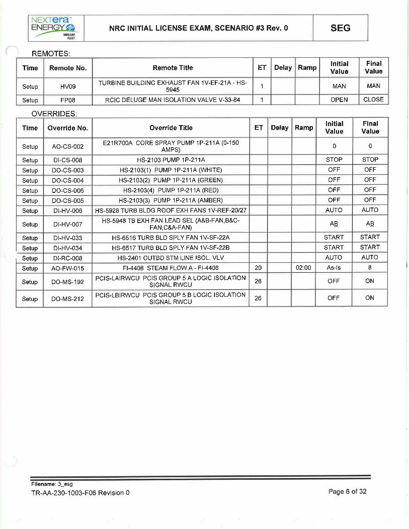
SEGNRC lNlTlAL LICENSE EXAM, SCENARIO #3 Rev. 0NEXTETA"ENERGYø2
tugt
REMOTES
CLOSEOPEN1RCIC DELUGE MAN ISOLATION VALVE V-33-84FPOSSetup
MANMAN1TURBINE BUILDING EXHAUST FAN 1V-EF-214 - HS-
5945HVO9Setup
FinalValue
lnitialValueRampDelayETRemote TitleRemote No.Time
OVERRIDES:
ONOFF26PCIS-LBIRWCU PCIS GROUP 5 B LOGIC ISOLATIONSIGNAL RWCUDO-MS-212Setup
ONOFF26PCIS-LAIRWCU PCIS GROUP 5 A LOGIC ISOLATIONSIGNAL RWCUDO-MS-192Setup
8As-ls02:0020FI-4408 STEAM FLOW A - FI-4408AO-FW-o15Setup
AUTOAUTOHS-2401 OUTBD STM LINE ISOL. VLVDt-RC-008
STARTSTARTHS-6517 TURB BLD SPLY FAN 1V-SF-228Dt-HV-034
STARTSTARTHS-6516 TURB BLD SPLY FAN 1V-SF-224Dt-HV-033Setup
ABABHS-5948 TB EXH FAN LEAD SEL (A&B-FAN,B&C-FAN,C&A-FAN)
Dt-HV-007Setup
AUTOAUTOHS-5928 TURB BLDG ROOF EXH FANS 1V-REF-20127Dt-HV-006Setup
OFFOFFHS-2103(3) PUMP 1P-2114 (AMBER)DO-CS-005Setup
OFFOFFHS-2103(4) PUMP 1P-2114 (RED)DO-CS-006Setup
OFFOFFHS-2103(2) PUMP 1P-2114 (GREEN)DO-CS-004Setup
OFFOFFHS-2103(1) PUMP 1P-2114 (WHlrE)DO-CS-003Setup
STOPSTOPHS-2103 PUMP 1P-2114Dt-cs-008Setup
00E21R700A CORE SPRAY PUMP 1P-2114 (0-150AMPS)AO-CS-002Setup
FinalValue
lnitialValueRampDelayETOverride TitleOverride NoTime
Setup
Setup
Filename:3_esg
TR-AA-230-1 003-F06 Revision 0 Page 8 of 32

SEGNRC lNlTlAL LICENSE EXAM, SCENARIO #3 Rev.0NEXTETA"
=Yær6
SCHEDULE FILES:
RE.4448A MAIN STEAM LINE AModify malfunction rm02re4448a to 55 in300
30
MO24OO THERMAL OVERLOAD BREAKER TRIPDelete malfunction RC1 0A22Setup
RE-9179 TURBINE FRONT STANDARDlnsert malfunction rmO1re9179 to 57.00000in 600 after 180
28
RE-9160 TURBINE LUBE OIL AREAlnsert malfunction rmO1re9160 to 61.00000in 600 after 18028Setup
RE-9159 REACTOR FEED PUMP AREAlnsert malfunction rmO1re9159 to 59.00000in 600 after 180
28Setup
RE-9158 CONDENSATE PUMP AREAlnsert malfunction rmO1re9158 to 55.00000in ô00 after 180
28Setup
RE-4448D MAIN STEAM LINE Dlnsert malfunction rm02re4448d to45.00000 in 120 after 180
28Setup
RE-44488 MAIN STEAM LINE Blnsert malfunction rm02re444ïb to44.00000 in 120 after 180
28Setup
RE-4448C MAIN STEAM LINE CI nsert malfunction rm02re4448c to45.00000 in 120 after 18028Setup
RE-44484 MAIN STEAM LINE AI nsert malfu nction rm02 re4448a to49.00000 in 120 after 18028Setup
CONTROL ROD SCRAMS- ROD 18-07lnsert malfunction rd081807 after 401Setup
RPV PRESS SWITCH PS4549 FAILURElnsert malfunction RR38A after 401Setup
Operating Basis Earthquake Eventlnsert malfunction zz02 delete in 50 after30
1Setup
0.01 G Recorders Operatinglnsert malfunction zz01 delete in 30 after30
1Setup
0.01 G Recorders Operatinglnsert malfunction zz01 delete in 201Setup
DescriptionActionEvent@ TimelLT3Actions.sch
Setup
Conduct simulator crew pre-scenario brief using TR AA-230-1007-F06, Simulator lnstructorPre-Exercise Checklist
lf surrogate operators are to be used, brief them using TR-AA-230-1007-F11, Surrogate BriefChecklist
Filename:3_esg
TR-AA-230-1 003-F06 Revision 0 Page 9 of 32

SEGNRC lNlTlAL LICENSE EXAM, SCENARIO #3 Rev. 0NEXTETA''
=Y*txg
SHIFT TURNOVER INFORMATION. Today, Night Shift
o Temperatures in the 80's. Eastern lowa has the potential for severe weather. Several strongstorms are forming in the Dakota's and Western Minnesota,
o Plant power -100o/o, with corresponding MWe, MWth, and core flow
o Protected Train - "8"
. Procedures or major maintenance in progress:
o "4" Core Spray is out of service for replacement of the breaker overcurrent relay. Work
" " 0
: "T;" ff : ï,iäi"i i:i tii: :ff i:l i":i å iï:, ll ääi; ^ ",,. Technical Specification Action statements in effect:
o DAEC is in compliance with all LCO's
o A" Core Spray is out of service for replacement of the breaker overcurrent relay. Workexpected to finish tomorrow morning with operability run on days tomorrow. LCO 3.5.1Condition B, daY 2 of 7 .
o Plant PRA Status
o CDF: 1.34 x 10⁻⁶, GREEN, I year to Yellow ICDP
o LERF 3.27 x l0-7, GREEN, 1 year to Yellow ILERP
o Evolutions in progress or planned for upcoming shift:
o Alternate running RBCCW pumps from 'B' & 'C' running to 'A' & 'C' running for motorinspections on 'B' RBCCW pump IAW Ol 414 SectionT .1.
o Lower power by 5o/o IAW lPOl 3, Power Operations (35o/o-100% Rated Power) to assistin PPC Maintenance and HPCI testing
. RE recommends only lowering Rx Recirc by l Mlbm/hr due to load line concerns
Comments, problems, operator workarounds, etc.
o One extra NSPEO available in Work Control
o Radwaste Operator is NSPEO qualified
a
Filename:3_esg
TR-AA-230-1 003-F06 Revision 0 Page 10 of 32

NEXTETA'
=Yry NRC lNlTlAL LICENSE EXAM, SCENARIO #3 Rev. 0 SEG
lPot 3
Switch runningRBCCW pumps
Whencontacted asany dept. inorganization:
TIME/NOTES
Booth Gommunicator:Acknowledge the request.
INSTRUCTOR ACTIVITY
CREW. Lower reactor power by 5o/o to assist in PPC Maintenance and HPCI
testing
RO
. Lower reactor power by 5o/o IAW lPOl 3 as follows:o At 1C04, reduce RECIRC MG SET A and B SPEED CONTROL in small
equal increments to lower core flow by approximately lMlb/hr,maintaining balanced Recirc lop flow, while closely monitoring thePower to Flow Map, so as not to exceed MELLLA, as directed by theCRS/OSM.
. lnsert control rods per the cunent Control Rod Withdrawal SequenceSheets to lower power by approximately 40 MWth or as directed by theCRS/OSM.
CRS
o Direct and observe reactivity manipulations to achieve a 5Yo reduction inreactor power
CREW. Switch running RBCCW pumps IAW Ol 414 section 7.1
RO
. Place the Standby RBCCW pump handswitch on 1C06 in the STARTposition
. Verify that the Standby RBCCW pump starts
. Place the handswitch for the RBCCW pump that is to be secured in theSTOP position
. Verify that RBCCW Pump Disch Header LO Pressure (1C068, D-3) isreset
o Place the handswitch for the secured RBCCW Pump in AUTOCRSo The CRS will direct switchinq runninq RBCCW Pumps
EXPECTED STUDENT RESPONSÉ
Filename: 3_esg
TR-AA-230-1 003-F06 Revision 0 Page11ot32

NEXIera"=Yry NRC lNlTlAL LICENSE EXAM, SCENARIO #3 Rev. 0 SEG
Earthquake
After the crewreduces powerby -5o/o and atthe direction ofthe floorinstructor:
The followingscripts are onthe followingpages:
Whencontacted asany dept. inorganization:
TIME/NOTES
Simulator OperatorAGTIVATE ET 1
This will cause the 0.01G recorder alarm torun; and then, 30 seconds later, an OBE
with additional malfunctions.
Booth Gommunicator:HPCI Suction Swap/Torus LevelAlarms -
Pg. 15
PS-4549/Half Scram Pg. 16
HCU 18-07 - Pg. 17118
Booth Communicator:Acknowledge the request.
INSTRUCTOR ACTIVITY
CREW. Enter and carry out the actions of AOP 901, Earthquake.
CRSo Direct Crew Response to an Earthquake Condition.
. lF the amber DESIGN BASIS EARTHQUAKE, or amber OPERATINGBASIS EARTHQUAKE lights are ON, and not a malfunction, THENcommence shutting down the reactor to be in cold shutdown within 24hours.
o Enter EOP 2 T/L on High/Low Torus Water Level (may be administrativelyexited).
o Direct Health Physics to perform radiation surveys of the normallyaccessible areas inside DAEC Buildings, and the site grounds includingthe lndependent Spent Fuel Storage lnstallation.
. Direct chemist to review KAMAN data and perform sensor checks.o Direct control room operators monitor the control room panels for changes
in some of the following critical plant parameters
EXPECTED STUDENT RESPONSE
Filename:3_esg
TR-AA-230-1 003-F06 Revision 0 Page 12 o1 32

NEXTETA'F:NEFÍGY ¿Z
--- nã¡¡¡-mNRC lNlTlAL LICENSE EXAM, SCENARIO #3 Rev. 0 SEG
Filename: 3_esg
TR-AA-230-1 003-F06 Revision 0
lf contacted asDuty StationManager:
lf contacted asHP orChemistry:
lf contacted asan in-plantoperator:
TIME/NOTES
Booth Communicator:Acknowledge the request.
Booth Gommunicator:Acknowledge the request to perfrominside and outside plant walkdowns.
Keep track of which operator has beensent to what location in the plant.
Booth Gommunicator:Acknowledge the request.
INSTRUCTOR ACT¡VITYCREW. Enter and carry out the actions of AOP 901, Earthquake
ROo Respond to an Earthquake Condition.. Monitor reactor power, pressure, and level on 1C05.o Monitor for any Control Rod out of position.o At 1C06, verify River Water Supply system integrity by:
. Verify all available RWS pumps will start and deliver >6000 gpmflow.
. Using HS 4918, RIVER WATER SUPPLY LOOP SELECT switch,select A CV4915 and B CV4914, one at a time, to verify RWSmakeup flow can be established with each loop ensuring RWSpiping is intact.
o Monitor Process and Area Radiation Monitoring System channels onPanels 1C10 and 1C11.
. Send operators, with portable radiation monitors, to perform a quick walkthrough of the plant to determine the general condition of the plantstructure and system's integrity, and immediately report back anydamage to the Control Room.
EXPECTED STUDENT RESPONSE
Page 13 of 32

NÐCtera",Yra,¿k NRC lNlTlAL LICENSE EXAM, SCENARIO #3 Rev. 0 SEG
Earthquake
Torus LevelAlarms
Earthquake
HPCI SuctionSwap
TIME/NOTES INSTRUCTOR ACTIVITY
CREWa Respond to the Torus Level annunciator 1C038 (D-9)
ROa Monitor the Torus level on URS 4384 (Channel 3) and UR 4385
(Channel 2) at 1C29 or LR4396A/B at 1C09.Verify the AUTOMATIC ACTIONS have occurred.a
CRSa Enter EOP 2 on T/L (may be administratively exited)
CREWa Respond to the HPCI Suction Transfer annunciator 1C03C D-4
RO. Confirm the Torus high level condition at 1C03 on Ll-43974 / B WR
TORUS LEVEL indicators, or at 1C09 on LR-43964 / B TORUSLEVEL.
o Verify the AUTOMATIC ACTIONS have occurred.. lf Hl TORUS LEVEL is confirmed, then enter EOP-2 (Primary
Containment Control). /CRS
a Enter EOP 2 on T/L (may be administratively exited)
EXPECTED STUDENT RESPONSE
Filename:3_esg
TR-AA-230-1 003-F06 Revision 0 Page 14 of 32

NEXTETA*
=Ysg NRC lNlTlAL LICENSE EXAM, SCENARIO #3 Rev. 0 SEG
Segment 1
Earthquake
PS-4549
T¡ME/NOTES
Evaluator Note:lF the crew checks the condition of C71A-
K5A inform the operator that the relayfingers are toward the cover. (De-energized
position, but do not directly say it is de-energized) All other relays are as seen.
Evaluator Note:
The crew will determine that PS4549 hasfailed. The crew will not be able to correct
the cause of the half scram, or reset it.
INSTRUCTOR ACT¡VITY
Respond to the REACTOR VESSEL HIGH PRESSURE TRIPannunciator 1C058 C-4
Respond to the "A' RPS AUTO SCRAM annunciator 1C054 A-2
At 1C05, confirm Reactor pressure high on PR-4563/4564, REACTORPRESSU RE/REACTOR WATER LEVEL.
Verify Scram Group A12 3 4 indicating lights are off.
ldentify the cause of the A RPS Auto Scram.
Enter the applicable Tech Specs:. LGO 3.3.1.1 RPS lnstrumentation Function 3 is not
OPERABLE - Gondition A; required action 4.1 Place channelin trip in 12 hours or A.2 Place associated trip system in trip in12 hours.
CREWa
a
RO
a
o
a
CRS
a
EXPECTED STUDENT RESPONSE
Filename: 3_esg
TR-AA-230-1 003-F06 Revision 0 Page 15 of32
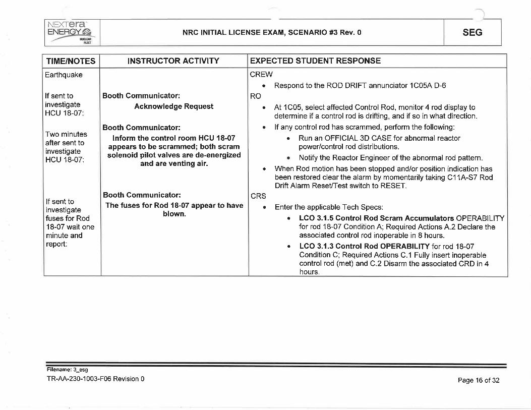
NFXTETA-NRC lNlTlAL LICENSE EXAM, SCENARIO #3 Rev. 0 SEG
Earthquake
lf sent toinvestigateHCU 18-07
Two minutesafter sent toinvestigateHCU 18-07:
lf sent toinvestigatefuses for Rod18-07 wait oneminute andreport:
TIME/NOTES
Booth Gommunicator:Acknowledge Request
Booth Gommunicator:lnform the control room HCU l8-07
appears to be scrammed; both scramsolenoid pilot valves are de-energized
and are venting air.
Booth Communicator:The fuses for Rod 18-07 appear to have
blown.
INSTRUCTOR ACTIV¡TY
CREWa Respond to the ROD DRIFT annunciator 1C054 D-6
At 1C05, select affected Control Rod, monitor 4 rod display todetermine if a control rod is drifting, and if so in what direction.
lf any control rod has scrammed, perform the following:
. Run an OFFICIAL 3D CASE for abnormal reactorpower/control rod distributions.
. Notify the Reactor Engineer of the abnormal rod pattern.
When Rod motion has been stopped and/or position indication hasbeen restored clear the alarm by momentarily taking C11A-S7 RodDrift Alarm ReseUTest switch to RESET.
Enter the applicable Tech Specs:o LCO 3.1.5 Control Rod Scram Accumulators OPERABILITY
for rod 18-07 Condition A; Required Actions 4.2 Declare theassociated control rod inoperable in I hours.
. LGO 3.1.3 Gontrol Rod OPERABILITY for rod 18-07Condition C; Required Actions C.1 Fully insert inoperablecontrol rod (met) and C.2 Disarm the associated CRD in 4hours.
RO
a
a
CRS
a
a
EXPECTED STUDENT RESPONSE
Filename: 3_esg
TR-AA-230-1 003-F06 Revision 0 Page 16 of 32

NEX|era'=Yjç,& NRc lNlTlAL LICENSE EXAM, SCENARIO #3 Rev. 0 SEG
Earthquake
AOP 255.2
Earthquake
AOP 255.1
lf contacted asReactorEngineer:
Two minutesafter contactedas RE:
TIME/NOTES
Booth Communicator:Acknowledge Request
Booth Gommunicator:Report that there is no current issue
with leaving 18-07 inserted.
INSTRUCTOR AGTIVITY
CREW
a Perform actions of AOP 255.2 for the unplanned power change
RO
a Place one APRM recorder in each trip system to fast speed to monitorfor APRM undamped oscillations greater than normal.
CRSa Direct actions of AOP 255.2
CREWa Perform actions of AOP 255.1 in the mispositioned control rod section
RO
. Once power has stabilized, manually initiate an Official 3D Case
. Verify thermal limits on the official 3D Case.
CRS
o Direct actions or AOP 255.1
. Contact RE and Ops Manager
EXPECTED STUDENT RESPONSE
Filename: 3_esg
TR-AA-230-1 003-F06 Revision 0 Page17 oÍ32
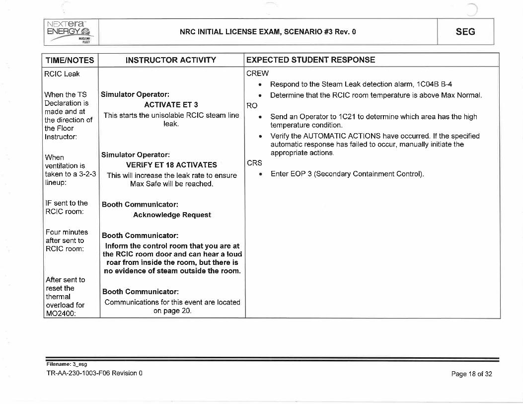
NÐ(TETA'
=Yry NRC lNlTlAL LICENSE EXAM, SCENARIO #3 Rev. 0 SEG
RCIC Leak
When the TSDeclaration ismade and atthe direction ofthe Floorlnstructor:
Whenventilation istaken to a 3-2-3lineup:
lF sent to theRCIC room:
Four minutesafter sent toRCIC room:
After sent toreset thethermaloverload forMO2400:
T¡ME/NOTES
Simulator Operator:ACTIVATE ET 3
This starts the unisolable RCIC steam lineleak.
Simulator Operator:VERIFY ET 18 ACTIVATES
This will increase the leak rate to ensureMax Safe will be reached.
Booth Gommunicator:Acknowledge Request
Booth Gommunicator:lnform the control room that you are at
the RGIC room door and can hear a loudroar from inside the room, but there is
no evidence of steam outside the room.
Booth Gommunicator:Communications for this event are located
on page 20.
¡NSTRUCTOR ACTIVITY
CREWa Respond to the Steam Leak detection alarm, 1C048 B-4
Determine that the RCIC room temperature is above Max Normala
RO
a Send an Operator to 1C21to determine which area has the hightemperature condition.
Verify the AUTOMATIC ACTIONS have occurred. lf the specifiedautomatic response has failed to occur, manually initiate theappropriate actions.
a
CRSa Enter EOP 3 (Secondary Containment Control).
EXPECTED STUDENT RESPONSE
Filename: 3_esg
TR-AA-230-1 003-F06 Revision 0 Page 18 of 32

NEXTETAF]NF:PíGYØÆ
,-- ffiE
NRC lNlTlAL LICENSE EXAM, SGENARIO #3 Rev. 0 SEG
RCIC Leak
lF sent to openbreaker for MO-24Q1:
lf sent to closeMO-2401manually:
After sent toclose MO-2401and at thedirection of theFloor lnstructor:
TIME/NOTES
Simulator Operator:Acknowledge the direction and brief,
wait 2 minutes thenAGTIVATE ET 14
THEN
Booth GommunicatorGontact the Gontrol Room and report
the breaker for MO-2401 is open.
Booth CommunicatorAcknowledge Request
Booth GommunicatorReport to the Gontrol Room that you
cannot get MO-2401 to move.
INSTRUCTOR ACTIVITY
Crewo lmplement the actions of EOP 3, Secondary Containment Control.
RO
o Starts ESW for RCIC Room Coolerso Operates available main plant supply and exhaust fans.. Start 1V-EF-1 ,1V-EF-2, and 1V-EF-3 MAIN PLANT EXHAUST FANS by
positioning the following handswitches to START and verify theirrespective dampers indicate OPEN:
. Fan Handswitch Panel Damper
. 1V-EF-1 HS-7613 1C23A. 1V-AD-16U
. 1V-EF-2 HS-7614 1C238 1V-AD-16V
. 1V-EF-3 HS-7615 1C23C 1V-AD-16W¡ Start the Reactor Building Exhaust Fans by positioning the following
handswitches to START:. Fan Handswitch Panelo 1V-EF-114 HS-76114 1C23Ao 1V-EF-118 HS-76118 1C238
o Start the Reactor Building Supply Fans by positioning the followinghandswitches to START:
. Fan Handswitch Panelo 1V-SF-104 HS-6512 1C234. 1V-SF-108 HS-6513 1C238¡ 1V-SF-10C HS-6514 1C23C
. lnserts a manual reactor scram
EXPECTED STUDENT RESPONSE
Filename: 3_esg
TR-AA-230-1 003-F06 Revision 0 Page 19 of32

NEXTETA'
=Yry NRC lNlTlAL LICENSE EXAM, SCENARIO #3 Rev. 0 SEG
EOP 1
When theMODE switch isplaced inSHUTDOWN:
After the scramand whenRC10A hasbeen deleted:
EOP 3 cont.
TIME/NOTES
Simulator Operator:VERIFY ET 22 ACITVATES
When the RO takes the Mode Switch out ofRUN. This begins the RWGU leak (isolable)
starts, and isolates the RCIC steam leak.
Booth CommunicatorGontact the Control Room and reportthat the thermal overload for MO-2400
has reset.
¡NSTRUCTOR ACTIVITY
CREW. lmplements the actions of EOP 1, RPV Control.
RO
o lnserts a manual reactor scram.o Places the MODE switch in SHUTDOWN.
CRS. Directs inserting a manual reactor scram.o Directs a RPV level band of 170-211" using condensate and feedwater.o Directs a RPV pressure band of 800-1055 psig using turbine bypass
valves.
o Directs commencing a cooldown to lessen the driving head on the leak inthe RCIC Room.
CRS. Directs starting ESW for RCIC Room Coolers
. Directs operating available main plant supply and exhaust fans.
. Properly placekeeps in EOP 3, Secondary Containment Control.
. lsolates all systems discharging into the area except systems required tobe operated by EOPS OR required to suppress a fire.
. Determines that RPV pressure reduction will decrease leakage intosecondary containment.
. Before any parameter reaches is Max Safe Operating Limit:
o Enter EOP 1. (CRITICAL)
EXPECTED STUDENT RESPONSE
Filename: 3_esg
TR-AA-230-1 003-F06 Revision 0 Page29 of 32
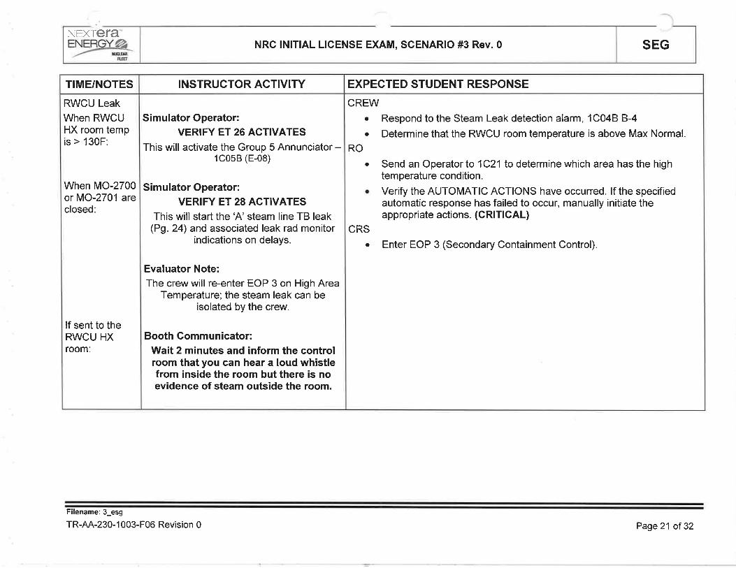
NEXTETA
=Y:ry NRC lNlTlAL LICENSE EXAM, SCENARIO #3 Rev. 0 SEG
RWCU Leak
When RWCUHX room tempis > 130F:
When MO-2700or MO-2701 areclosed:
lf sent to theRWCU HXroom:
TIME/NOTES
Simulator Operator:VERIFY ET 26 ACTIVATES
This will activate the Group 5 Annunciator -1C058 (E-08)
Simulator Operator:VERIFY ET 28 ACTIVATES
This will start the 'A' steam line TB leakPg. 2q and associated leak rad monitor
indications on delays.
Evaluator Note:The crew will re-enter EOP 3 on High Area
Temperature; the steam leak can beisolated by the crew.
Booth Gommunicator:Wait 2 minutes and inform the controlroom that you can hear a loud whistlefrom inside the room but there is noevidence of steam outside the room.
INSTRUCTOR ACTIVITY
CREWa Respond to the Steam Leak detection alarm, 1C048 B-4
Determine that the RWCU room temperature is above Max Normal.a
RO
a Send an Operator to 1C21to determine which area has the hightem perature condition.
Verify the AUTOMATIC ACTIONS have occurred. lf the specifiedautomatic response has failed to occur, manually initiate theappropriate actions. (CRIT¡CAL)
a
CRS
a Enter EOP 3 (Secondary Containment Control).
EXPECTED STUDENT RESPONSË
Filename:3_esg
TR-AA-230-1 003-F06 Revision 0 Page21 oÍ 32

NEXIefa"=--%- NRC lNlTlAL LICENSE EXAM, SGENARIO #3 Rev. 0 SEG
Segment 3
RWCU Leak
T¡ME/NOTES INSTRUCTOR ACT¡VITY
CREW. Respond to the steam leak in RWCU per ARP 1C058 E-8
RO
. Check the amber lights on the PCIS status board on 1C04 to determine ifa half or a full Group 5 lsolation has occurred.
o Verify completion of the Group 5 lsolation by one of the following means:. Verify that the individual valves from Section 2.0 AUTOMATIC
ACTIONS are closed, OR. On the PCIS status board, verify that the green ALL VALVES
CLOSED lights are on to coincide with the amber ISOLATIONSIGNAL lights that are on, allowing time for the valves to close, OR
o Check the CIMS Printer PRT-1 which will print out Group 5 valveswhich failto close on an isolation signal.
EXPECTED STUDENT RESPONSE
Filename:3_esg
TR-AA-230-1 003-F06 Revision 0 Page22 of 32

NEXTETA"ENERGYøZ-/- rÃ'er¡m
NRG lNlTlAL LICENSE EXAM, SCENARIO #3 Rev. 0 SEG
Fuel Failure /Release
4 minutes afterthe reactor isscrammed:
TIME/NOTES
Simulator Operator:VERIFY the following:
ms04a and rm09rm5945 have insertedand are ramping
AND
Booth Gommunicator:Gontact the control room as HP
personnel and report that there is loudnoise and rapidly getting humid and hot
in the turbine building north end. Youhave left the area.
INSTRUCTOR ACTIVITY
CREW. Determine that a steam leak exists in the Turbine Building and attempt to
close the MSlVs.
. lf delay closing the MSlVs, a Group 1 lsolation will occur.
¡ Recognize both "4" MSIVs failto close.
EXPECTED STUDENT RESPONSE
Filename:3_esg
TR-AA-230-1 003-F06 Revision 0 Page 23 of 32

NEXIera'ENERGYøZ-/- unrln
ffi
NRC ¡NlTlAL LICENSE EXAM, SCENARIO #3 Rev.0 SEG
Fuel Failure /Release
ReactorBuilding ARMalarm
TIME/NOTES INSTRUCTOR ACTIVITY
CREW. Respond to the REACTOR BLDG ARM Hl RAD alarm, 1C048 A-6. ln addition to EOP 3, the crew will determine that the cause for the
radiation rise in the Reactor Building rooms is potentially due to a fuelfailure and enter AOP 672.2
RO
. Perform the following:. At 1C11, monitor ARM lndicator and Trip Units to determine the
affected Area within the Reactor Building.o Check Computer Point 8571, REACTOR BLDG RAD HIGH.
. At 1C02, confirm the Area High Radiation conditions on RR-9150 AREARADIATION MON ITORING recorder.
. lf an actual high radiation condition exists in the affected area enter EOP 3(Secondary Containment Control).
CRSo Enter EOP 3 on High Radiationo Direct the actions of AOP 672.2
EXPECTED STUDENT RESPONSE
Filename: 3_esg
TR-AA-230-1 003-F06 Revision 0 Page24 of 32
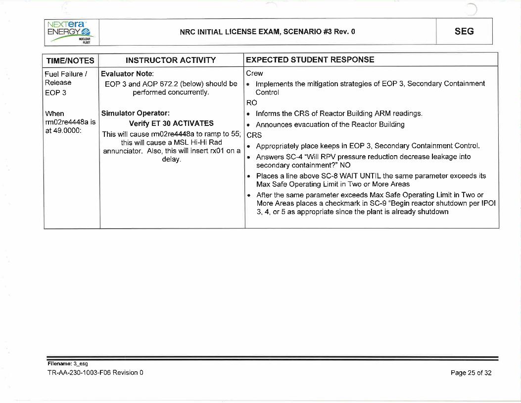
NEXTETA"NRC lNlTlAL LICENSE EXAM, SGENARIO #3 Rev. 0 SEG
Fuel Failure /Release
EOP 3
Whenrm92re4448aisat 49.0000:
TIME/NOTES
Evaluator Note:
EOP 3 and AOP 672.2 (below) should beperformed concurrently.
Simulator Operator:Verify ET 30 ACTIVATES
This will cause rm02re4448a to ramp to 55;this will cause a MSL Hi-Hi Rad
annunciator. Also, this will insert x01 on adelay.
INSTRUCTOR ACTIVITY
Crew. lmplements the mitigation strategies of EOP 3, Secondary Gontainment
Control
RO
. Informs the CRS of Reactor Building ARM readings.
. Announces evacuation of the Reactor Building
CRS. Appropriately place keeps in EOP 3, Secondary Containment Control.
. Answers SC-4'Will RPV pressure reduction decrease leakage intosecondary containment?' NO
¡ Places a line above SC-8 WAIT UNTIL the same parameter exceeds itsMax Safe Operating Limit in Two or More Areas
. After the same parameter exceeds Max Safe Operating Limit in Two orMore Areas places a checkmark in SC-9 "Begin reactor shutdown per lPOl3,4, or 5 as appropriate since the plant is already shutdown
EXPECTED STUDENT RESPONSE
Filename:3_esg
TR-AA-230-1 003-F06 Revision 0 Page2î of 32

NÐCtera"=Yry NRC lNlTlAL LICENSE EXAM, SCENARIO #3 Rev. 0 SEG
lf contacted asHP:
T¡ME/NOTES
Booth Gommunicator:Acknowledge the i nformation.
INSTRUCTOR ACTIV¡TY
Crew. lmplements the mitigation strategies of AOP 672.2, Offgas Radiation/
Reactor Coolant High ActivityRO
. Respond to Off Gas Radiation /Reactor Coolant High Activity Condition
. Notify Health Physics of increasing activity levels.
. Bypass the Main Condenser High Backpressure trip on 1C15 and 1C17 .
o Establish MSIV leakage treatment system flowpath.
CRS. Direct Crew Response to Off-Gas Radiation/Reactor Coolant High Activity
Condition. Establish critical parameter monitoring of in-plant radiation levels and
offsite release rates, as priorities allow.. Request chemistry department perform a reactor coolant isotopic analysis
and Offgas Pretreat analysis.o lF a valid Main Steam Line Hi Rad (1C058, D-2) is received and the
reactor is shutdown THEN cooldown and depressurize the reactor usingthe suppression pool as a heat sink as follows:o Establish reactor pressure control with SRVs prior to closing the MSlVs.. Cooldown the reactor with the main condenser unavailable per lPOl 4.. Notify HP that rad levels in the torus room and areas of the reactor
building may significantly rise.
EXPECTED STUDENT RESPONSÉ
Filename:3_esg
TR-AA-230-1 003-F06 Revision 0 Page26 of 32

NEXIera'=Yr*& NRC lNlTlAL LICENSE EXAM, SCENARIO #3 Rev. 0 SEG
After the TBKAMANexceeds theALERT EALlevel:
lflwhen directedto stop fans:
lF the crewlowers RPVpressure priorto ED:
TIME/NOTES
Booth Gommunicator:Wait 3 minutes and report that the1V-EF-21"A" and "8" Fans were
running and that you secured the"B"Fan. The "A" Fan's hand-switch,
HS-5945, broke off.
Simulator Operator:VERIFY ET 24 ACTIVATES
This will close the bypass valves.
INSTRUCTOR AGTIVITY
Crew. lmplements the mitigation strategies of EOP 4, Radioactivity Release
Control
RO
. Perform actions of EOP 4
o lF Group 3 isolation exists AND Reactor Building Kaman Monitors have aHl-HlAlarm THEN
. Stop main plant exhaust fans.
. Stop turbine building supply fans.
. Verify at least one turbine building exhaust fan operating in high speed.
. Verify Group 3 isolation complete.o Reduce Offsite Radioactivity Release Rate with a Primary System
Discharging Outside of Containmento Attempts to isolate all primary systems discharging radioactivity outside
the primary and secondary containments except for those systemsrequired to be operated by EOPs
. Attempts to close at least one of the "4" steam line MSIV's using thehandswitch and the test switch. (May have already been attempted)
o Emergency Depressurization is required.
EXPECTED STU DENT RESPONSE
Filename:3_esg
TR-AA-230-1 003-F06 Revision 0 Page27 of 32

NEXTCTA'ENE@ffi
NRC lNlT¡AL LICENSE EXAM, SCENARIO #3 Rev. 0 SEG
After the TBKAMANexceeds theALERT EALlevel:
TIME/NOTES INSTRUCTOR ACTIVITY
CRS¡ Direct crew response for Performance of EOP 4
¡ Directs isolating all primary systems discharging radioactivity outside theprimary and secondary containments except for those systems required tobe operated by EOPs.
. WAIT UNTIL any primary system is discharging radioactivity into areasoutside the primary and secondary containments
. Begins reactor shutdown per lPOl 3, 4, or 5 as appropriate (alreadycompleted)
o BEFORE offsite radioactivity release rate reaches a General Emergency
EXPECTED STUDENT RESPONSE
Filename:3_esg
TR-AA-230-1 003-F06 Revision 0 Page29 ol 32

NEXIETA
=Yr*& NRC lNlTlAL LICENSE EXAM, SCENARIO #3 Rev. 0 SEG
When the TBKAMANexceeds theSITEEMERGENCYEAL level andis approachingthe GENERALEMERGENCYlevel, the crewEmergencyDepressurizes
As RPVpressure islowered past880#:
TIME/NOTES
Simulator Operator:VERIFY ET 24 ACTIVATES
This will close the bypass valves
INSTRUCTOR ACTIVITY
Crew. lmplements the mitigation strategies of Emergency Depressurization.
RO
. lnstall Defeat 11 (if not done previously).
. Maintains RPV level170-211" using directed control system.
. Reports torus water level.
o Opens 4 ADS SRVs.. Commences to initiate actions to place shutdown cooling in service.
CRS
¡ Directs Defeat 11 installation (if not done previously).
o Directs RPV level be maintained 17Q-211" using directed controlsystem. Verifies torus level greater than 4.5'.. Directs opening 4 ADS SRVs.. Continues RPV depressurization using SRVs.
¡ WAIT UNTIL shutdown cooling interlock clears and further cooldown isrequired.
¡ Directs continuing to cold shutdown conditions with shutdown coolingusing only RHR pumps NOT required to maintain RPV level above 170"
EXPECTED STUDENT RESPONSE
Filename: 3_esg
TR-AA-230-1 003-F06 Revision 0 Page29 of32

When RPVpressure islowering toestablishdepressurizedconditions,RPV waterlevel is beingcontrolled, andat the directionof the floorinstructor:
TIME/NOTES
Simulator OperatorPlace the simulator in FREEZE.
Floor lnstructorPerform a crew update and announce tothe crew the simulator is in freeze andthe scenario is complete.
INSTRUCTOR ACTIVITY EXPECTED STUDENT RESPONSE
NEXTETAEYæJ6, NRC lNlTlAL LICENSE EXAM, SCENARIO #3 Rev. 0 SEG
*** END OF SCENARIO **
Filename: 3_esg
TR-AA-230-1 003-F06 Revision 0 Page 30 of 32

SEGNRC lNlTlAL LICENSE EXAM, SCENARIO #3 Rev. 0NEXTETA'
=Ysr6QUANTITATIVE ATTRI BUTESMalfunctions:Before EOP Entry:
1. Operational Basis Earthquake
2. RPV Pressure Switch Failure, PS4549 fails high
3. Single rod scrams in
4. RCIC Steam Leak
After EOP Entry:
1. RWCU leak (isolable)
2. Fuel Failure
3. Steam Tunnel Steam Leak
4. Turbine Bypass Valve Failure
Abnormal Events:1. AOP 901
2. AOP 255.1
3. AOP 255.2
Maior Transients:1. Earthquake
2. Offsite Release
3. ED
Critical Tasks:1. #28: JF a primary System is discharging into Secondary Containment and any parameter is
above the Max Normal Operating Limit, THEN crew actions are taken to isolate all systems
discharging into the area except those required by EOPs or to suppress a fire.
{BWROG N/A}
2. #2g: lF the reactor is at power AND a primary system is discharging into secondarycontainment, THEN insert a manual scram before any parameter reaches the Max. Safe
Operating Limit. {BWROG SC 1.1}
3. #i2: lF a primary system is discharging outside secondary containment, THEN perform
Emergency RPV Depressurization before offsite release rates reach General Emergency
levels. {BWROG RP 1.1}
Filename:3_esg
TR-AA-230-1 003-F06 Revision 0
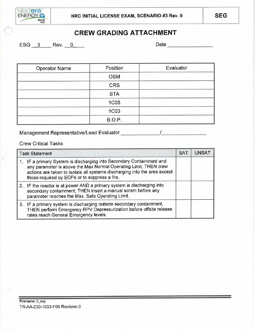
SEGNRC lNlTlAL LICENSE EXAM, SCENARIO #3 Rev. 0NEXTETA"EYærc-
CREW GRADING ATTACHMENT
ESG 3 Rev Date
Management Representative/Lead Evaluator
Crew Critical Tasks
B.O.P
1C03
1C05
STA
CRS
OSM
EvaluatorPositionOperator Name
3. lF a primary system is discharging outside secondary containment,THEN perform Emergency RPV Depressurization before offsite releaserates reach General Emergency levels.
2. lF the reactor is at power AND a primary system is discharging intosecondary containment, THEN insert a manual scram before anyparameter reaches the Max. Safe Operating Limit.
1. lF a primary System is discharging into Secondary Containment andany parameter is above the Max Normal Operating Limit, THEN crewactions are taken to isolate all systems discharging into the area exceptthose required by EOPs or to suppress a fire.
UNSATSATTask Statement
F¡lename:3_esg
TR-AA-230-1 003-F06 Revision 0

SEGSIMULATOR EXERCISE GUIDENEXTETA-EW-
F.¡tt
SITE: DAEC Revision #: 0
LMS ID: ESG AIt LMS Rev. Date: N/A
SEG TITLE: NRC lNlTlAL LICENSE EXAM, SCENARIO #ALT
SEG TYPE: [J Training X Evaluation
PRocRAM: nLOCT XLOIT nOther:
DURATION: -90 minutes
lDeveloped byl:
lnstructor/Developer Date
Reviewed by:
lnstructor (lnstructional Review) Date
Validated by:
SME (Technical Review) Date
Approved by:
Training Supervision Date
Approved by:
Training Program Owner (Line) Date
alt
TR-AA-230-1 003-F06 Revision 0 Page 1 of 23

SEGNRC lNlTlAL LICENSE EXAM, SCENARIO #ALT Rev.O
NEXIETAE\src-
SIMULATOR EXERCISE GUIDE REQUIREMENTSTerminal Objective This Evaluation Scenario Guide evaluates the Operators' ability to:
"Given the malfunctions presented in this ESG, the students will protect thepublic, protect plant personnel, and protect plant equipment, in accordancewith plant procedures."
EnablingObjectives
Evaluation Guide, no tasks are trained.
Prerequisites: Enrolled in Licensed Operator Continuing Training, License Operator lnitialTraining, Senior Reactor Operator- Certification Training
TrainingResources:
References:
Protected Gontent:,
OperatingExperience:Risk SignificantOperator Actions:
A. Ol 693.2, Rev. 51B. AOP 646 Rev. 23C. AOP 255.2 Rev.43D. AOP 264Rev.14E. AOP 573 Rev.6F. EOP2 Rev. 18G, EOP 1 Rev.20H. ATWS Rev.23l. ED Rev. 11
J. ATWS Rev. 23K. lPOl 4 Rev. 133L. lPOl 3 Rev. 152M. ARP 1C048 Rev. 81N. ARP 1C044 Rev. 62O. ARP 1C054 Rev. 82P. OP-AA-102-1003 Rev, 11
Q. Ol 644 QRC 2, Rev. 0R. Ol 149 QRC 4, Rev. 0S. Ol 153 QRC 1, Rev.4None
A. SimulatorB. Evaluation teamC. Operations Management RepresentativeD. Simulator DriverE. Phone TalkerF. Exam Proctor for custody of the crew between scenariosG. Simulator Video recording equipment
Evaluation Method: Dynamic Scenario graded in accordance with NUREG 1021 guidance
None
Filename: ESG alt
TR-AA-230-1 003-F06 Revision 0 Page2 of 23

SEGNRC lNlTlAL LICENSE EXAM, SCENARIO #ALT Rev.O
NEXTETA"EYWru¡f
Direct Crew Response for performance of the PC/P leg of EOP 26.64Direct Crew Response for performance of the DWT leg of EOP 26.63Direct Crew Response to perform /P to control RPV pressure during an ATWS6.57Direct Crew Response to perform /Q to reduce power/scram the reactor durinq ATWS6.56Direct Crew Response to Perform lnitialATWS Actions (/)6.55
Direct Crew Response to Control RPV lnjection prior to, during and subsequent toEmergency Depressurization during ATWS
6.52Direct Crew Response to Perform /L to Control Level Durinq an ATWS6.50Direct Crew Response for performance of RC/P leg of EOP 16.46Direct Crew Response for performance of initial EOP 1 actions (RC)6.45Direct Crew Response for performance of the RC/L leg of EOP 16.44Direct Crew Response for performance of Defeat 156.25Direct Crew Response to Perform EOP Defeat 116.21Direct Crew response to Loss of Reactor Recirculation Pump(s)5.58Direct Crew response to a Primary Containment ControlAbnormal Situation5.53Direct Crew Response to Loss of Feedwater Heating Condition5.19Direct Crew Responses to Power/Reactivity Abnormal Chanqe Condition5.03Direct Crew Actions to Perform the lmmediate Operator Responses to a Reactor Scram4.21Determine operability for TS required components1.02Senior Reactor OperatorPerform PC/P leg of EOP 295.64Perform DW/T leg of EOP 295.63Perform /Q to Reduce Reactor Power or Scram the Reactor95.57Perform /P to Control RPV Pressure During an ATWS.95.56Perform initialATWS actions (/)95.55Control RPV lniections prior to, during, and subsequent to ED during ATWS.95.52Perform /L to Control RPV Level during an ATWS95.50Perform actions of RC/P of EOP 195.46Perform initial EOP 1 actions (RC)95.45Perform actions of RC/L of EOP 195.44Perform Defeat 1595.25Perform EOP Defeat 1195.21Respond to Emergency Situations95.00Respond to Loss of Reactor Recirculation Pump(s)94.58Respond to Primary Containment Control Abnormal Situation94.53Respond to Loss of Feedwater Heating Condition94.1 9Respond to Power/Reactivity Abnormal Change Condition94.03Perform the lmmediate Operator Responses to a Reactor Scram93.22lnsert Control Rods using Single Notch72.02Alternate CRD Pumps10.03Respond to Annunciators1.04
Reactor OperatorTask TitleTask #
TASKS ASSOCIATED WITH SIMULATOR EXERCISE GUIDE
Filename: ESG alt
TR AA-230-1003-F06 Revision 0 Page 3 of 23

SEGNRC lNlTlAL LICENSE EXAM, SCENARIO #ALT Rev.0
NEXTETA"
=Yøarg
See CoverN/Alnitial development for
2017 NRC LO|TExamination
lnitial development for 2017NRC LOIT Examination
Rev.0 See CoverDATEREVIEWER
AR/TWR#REASON FOR CHANGEDESCRIPTION OF CHANGE# DATEPREPARER
UPDATE LOG: lndicate in the following table any minor changes or major revisions (as defined in TR-AA-230-1003)made to the material after initial approval. Or use separate Update Log form TR-AA-230-1003-F16.
Filename: ESG alt
TR-AA-230-1 003-F06 Revision 0 Page 4 of 23

SEGNRC lNlTlAL LICENSE EXAM, SCENARIO #ALT Rev.O
NEXI ETAENENGYø2
FLEgT
OVERVIEW / SEQUENCE OF EVENTS
ALL TIMES IN THIS SCENARIO ARE APPROXIMATE
The scenario may be terminated after all rods are in and RPV level is being restored7
The crew will determine that there is a hydraulic AïWS and transition to EOP ATWS. Thecrew will lockout ADS (CRITICAL), perform the ATWS QRC, inject SBLC, Terminate andPrevent injection (CRITICAL) and establish a level band until all rods are inserted(CRITICAL), and insert the control rods with the RIPS. (CRITICAL) Rods will be able to beinserted via Scram-Reset-Scram.
6
As Primary Containment pressures and temperatures rise the 'A' side enable containmentswitch will not function and MO-2000 will not open causing Drywell temperature to rise past280F. MO-2000 will be able to be opened through manual operations if an individual issent to open the valve.
5
A small leak in the drywell and rising drywell pressure. As temperature rises in the Drywell,the crew will insert a manual scram prior to Drywell temperature reaching 280F(cRrTrcAL).
4
Then the 'A' CRD pump will trip on overcurrent and three CRD accumulators alarm on lowpressure. Permission is given to stad standby pump IAW Ol 255. After the 'B' CRD Pumpis returned to service the CRD Accumulators remain in alarm on low pressure. The crewwill enter LCO 3.1.5 Gondition B.
3
Once the EHC pump swap is completed, the 'B' Recirc Pump will experience a 20o/orunback, the scoop tube will not be able to be locked until after the 'B' Recirc Pump speedis less than 75o/o, and the crew will enter LCO 3.4.1 Condition C. The 'B' Recirc Pump willexperience erratic parameters and will trip. The crew will lower power IAW lPOl 3.
2
The crew will swap running EHC pumps IAW Ol 693.2 Section 6.21
When the crew assumes the shift reactor power is approximately 100%. The'B' RHR Pump isinoperable due to breaker refurbishment; return time is approximately three days. After crewturnover, maintenance has requested immediately swapping running EHC pumps.
DescriptionEvent #
Filename: ESG alt
TR-AA-230-1 003-F06 Revision 0 Page 5 of 23

4.
5.
SEGNRC lNlTlAL LICENSE EXAM, SCENARIO #ALT Rev.O
NEXTETA-EYtsrc-
SIMULATOR SET UP INSTRUCTIONS
1 . Set NRC Exam Security for the Simulator per QF-1071-08
2. Perform simulator set up per TDAP 1839 Attachment 2, Simulator Setup Checklist.
3. Load the saved lC (in folder with this ESG) to a SNAPSHOT
a. Reset to that SNAPSHOT.
b. Place the Simulator in RUN
11
ORReset to lC 20, place the simulator in RUN and perform the following:a. lnsert event triggers, malfunctions, overrides and remotes per the tables below.
Have a second instructor verify that the auto triggers are setup as indicated below andevaluate to "FALSE" _Verify Malfunctions _Verify Remotes (Note that environmental remotes will already be timing)
Verify Overrides
Ensure MOL pull sheet is in the 1C058 hanging file.
Ensure EOOS has the same system status lineup as the start of the simulator scenario.
Setup control panel including equipment clearance tags, information tags, caution tags or othersite-specific devices used as an aid to the operator.
a. Place a Testing and Maintenance border on 1C038 (A-8) "B' RHR Pump 1P-2298 Trip orMotor Overload
b, Hang caution tags on the following:(1) HS-1915, B RHR PUMP 1P-2288
c. Hang Guarded System tags on the following:
(1) "B',ESW
(2) "B',RHRSW(3) "B',DG(4) 1p.4
(5) 1B,4
(6) 1B,44
Provide appropriate sh ift turnover documentation.
a. Have STP 3.4.2-01 Jet Pump Operability ïest available upon request.
RUN Schedule File .ESG alt.sch" and LEAVE lT RUNNING.
Fi lename: ESG alt
6.
7.
8.
9.
10
11
12
TR-AA-230-1003-F06 Revision 0 Page 6 of 23

SEGNRC lNlTlAL LICENSE EXAM, SCENARIO #ALT Rev.0NEXTETA-,Ynar6
EVENT TRIGGER DEFINITIONS
'B' Recirc Pump speed less than 75%zaorrr6211b <= 0.75'19
RPV water level less than or equal to 170"rrl <= 52317
Deletes RD073819ZD|RDHS18078(4) == 111
Manually ActivatedManually Activated1 ,3,5,7,9,13,15,21,23
Trigger Word DescriptionTrigger Losic StatementTrigger No.
MALFUNCTIONS:
UNLOCKUNLOCK'B'RECIRC SCOOP TUBE LOCK UP
(LOCK,UNLOCK)rr06Setup
ACTIVEINACTIVE1Spurious 20% Recirc Runback B Trainr136bSetup
7575HYDRAULIC LOCK SCRAM DISCHARGE
VOLUME IVARIABLE)rp05gSetup
Activelnactive17SPURIOUS GROUP 7 ISOLATIONms3210005:003RECIRC PUMP SHAFT SEIZURE- PMP Brr05b
ONON1C038 (A-08)'B' RHR Pump 1P-2298 TripOr Motor Overload
AN1C03B(8)Setup
1.5015 min13RECIRC LOOP RUPT - DESIGN BASESLOCA AT 100o/o - LOOP B
rr15bSetup
Activelnactive1 min30 sec
5Control Rod Accumulator Trouble - Rod38-1 I
RD073819Setup
Activelnactive5CRD Hvdraulic Pumo Trio - Pumo ARD11ASetup
Activelnactive1 min10 sec
5Control Rod Accumulator Trouble - Rod34-35
RD073435Setup
Activelnactive1 min5Control Rod Accumulator Trouble - Rod06-1 5
RD070615Setup
ACTIVEINACTIVE2:O03RECIRC M-G DRIVE MOTOR BREAKERTRIP - M-G B
RRO6BSetupFinal ValuelnitialValueRampDelavETMalfunction TitleMalf. No.Time
Setu
OVERRIDES
OFFON1:0021H5-2000(2) CONTATNMENT SPRAYMOV-2000 (RED)
DO-RH-133
OFFON1:0021HS-2000(1 ) CONTATNMENT SPRAYMOV-2OOO (GREEN)
DO-RH-132
NormalNormalHS-43218 GRP 7 CHAN B DW CLG ANDFAN OVR
Dt-PC-038Setup
offOnHS-1915(1) RHR PUMP 1P-2298 L|TES -(GREEN)
DO-RH-062Setup
offOnHS-1915(4) RHR PUMP '.lP-2298 LIrES -(AMBER)
DO-RH-065Setup
offOnHS-1915(3) RHR PUMP 1P-2298 LTTES -(RED)
DO-RH-064Setup
offOnHS-1915(2) RHR PUMP 1P-2298 L|ïES -(wHrTE)
DO-RH-063Setup
CLOSEAUTOHS-2OOO CONTAINMENT SPRAY MOV-2000
Dt-RH-076Setup
OFFOFFHS.19O3C CONT SPRAY VLV CTRLDt-RH-014Setup
Final Valuelnitial ValueRampDelayETMalfunction TitleMalf. No.Time
Setup
Setup
PageT of23Filename: ESG alt
TR-AA-230-1 003-F06 Revision 0

SEGNRC lNlTlAL LICENSE EXAM, SCENARIO #ALT Rev.O
NEXTETA',YSxø
fime
REMOTES:
OPENCLOSE27HS-2OOO CONTAINMENT SPRAY MOV-2000
Dt-RH-076(NEW)
Setup
FinalValuelnitialValueRampDelavETMalfunction TitleMalf. No.
TESTRUN2:0023ATWS TEST SW|TCH (AKA DEFEAT 12)
HS-1864A (RUN.TEST)rp03
Setup
TESTRUN2:3023ATWS TEST SW|TCH (AKA DEFEAT 12)HS-1863A
rp02Setup
OpenNormMAN OPER OF 'B' RHR PUMP (1P2298BREAKER)
RHlOSetup
10050l MIN15CRD PUMP 1P-2098 DISCHARGEVALVE V -17 -10 ISOLATION
RD04 (NEW)Setup
50100l MIN7CRD PUMP 1P-2098 DISCHARGEVALVE V-17 -10 ISOLATION
RDO4Setup
Final ValuelnitialValueRamoDelavETMalfunction TitleMalf. No.Time
SCHEDULE FILES:
'B'RECIRC SCOOPE TUBE LOCKuP (LOCK,UNLOCK)
Delete malfunction 110619Setup
CONTROL ROD ACCUMULATORTROUBLE- ROD 38-19
Delete malfunction rd073819 after 511Setup
CRD PUMP 1P-2O98 DISCHARGEVALVE V-17 -10 ISOLATION
Modify rd04 to 100 in 60 after 60o
DescriptionActionEvent@Time
ESG_alt
Setup
Conduct simulator crew pre-scenario brief using TR-AA-230-1007-F06, Simulator lnstructorPre-Exercise Checklist.
lf surrogate operators are to be used, brief them using TR-AA-230-1007-F11, Surrogate BriefChecklist
Filename: ESG alt
TR-AA-230-1 003-F06 Revision 0 Page I of 23

SHIFT TURNOVER INFORMATION
SEGNRC lNlTlAL LICENSE EXAM, SCENARIO #ALT Rev.0NEXTETA-EYær6-
. Today, Dayshift
o Warm, summer day, temperatures in the high 70's. No inclement weather expected.
o Plant power - -100o/o Rx Pwr with corresponding MWe, MWth and core flow.
. Protected train - "4"
o Procedures or major maintenance in progress:
o 'B' RHR Pump is inoperable because of a fault in the motor winding. Maintenanceexpects repairs to be completed in 3 days.
o Technical Specification Action statements in effect
o TS 3.5.1 Condition A, Day 1 of 30 day LCO, due to "B' RHR Pump inoperative
o TS 3.6.2.3, Condition A, Residual Heat Removal (RHR) Suppression Pool Cooling,Day 1 of 30 day LCO, due to "8" RHR Pump inoperative
Plant PRA/PSA Status including CDF/LERF & color
o CDF : GREEN 1.35 E-6, I YR TO YELLOW LCDP
o LERF: GREEN 3.328-7,lYR TO YELLOW ILERP
Evolutions in progress or planned for upcoming shift
o Maintenance has requested swapping running EHC pumps to allow for checks on therunning pump.
Comments, problems, operator workarounds, etc.
o One extra NSPEO available in Work Control
o Radwaste Operator is NSPEO qualified
o
a
o
Filename: ESG alt
TR-AA-230-1 003-F06 Revision 0 Page 9 of 23

NEXiera'NRC lNlTlAL LICENSE EXAM, SCENARIO #ALT Rev.0 SEG
After the crewhas taken theshift:
When contactedas organizationpersonnel:
T¡ME/NOTES
SIMULATOR EXERCISE GUIDE SCENARIO INSTRUCT¡ONS
Booth GommunicatorAcknowledge Request
INSTRUCTOR ACTIVITY
Crewo Switch running EHC pumps
RO
. At 1C07 , start standby EHC pump 1P-978 by momentarily placinghandswitch HS-36658 in the START position.
. Verify annunciator EHC PUMPS 1P97NB BOTH RUNNING (1C07A, C-4) is activated
. Verify both EHC pump 1P-97N8 amps have stabilized
. Stop EHC Pump 1P-974 by momentarily placing handswitch HS-36654in the STOP position
. Verify annunciators EHC PUMPS 1P-97N8 BOTH RUNNTNG and ECHPUMP 1P-97N8 HS NOT lN AUTO are reset
CRSo Direct switching running EHC pumps
EXPECTED STUDENT RESPONSE
Filename: ESG alt
TR-AA-230-1 003-F06 Revision 0 Page 10 of23

r¡¡Elæy-a,.- nnErn
RF
NEXTETA'NRC lNlTlAL LICENSE EXAM, SCENARIO #ALT Rev.O SEG
Recirc Runback
After EHCpumps areswapped and atthe direction ofthe floorinstructor:
When contactedas organizationpersonnel:
When contactedas plantpersonneltoinvestigate'B'Recirc Pump:
TIME/NOTES
SIMULATOR EXERCISE GUIDE SCENARIO INSTRUCTIONS
Simulator Operator
lnsert ET 1
This will cause 'B' Recirc Pump 20%runback and failure of 'B' Recirc Pump
Scoop Tube lock until speed is lower than75%.
Booth GommunicatorAcknowledge Request
Booth Gommunicator
Wait 2 minutes and inform ControlRoom that there is nothing abnormalabout the 'B' Recirc Pump, but will
continue to investigate.
INSTRUCTOR ACTIVITY
Crew
Respond to a'B' Recirc Pump 20% Runbacka
RO
CRS
. Attempt to lock'B' Recirc Pump Scoop Tube. (Will lock once pumpspeed is lower than 75%)
o Stabilize Reactor water level.
o When power is stabilized, plot location on the Stability Power / FlowMap
. Determine Recirc Pump speed mismatch is outside of acceptablelimits
. Comply with Tech Specs and Ol 264, Appendix 1
o Enter LCO 3.4.1 Condition C
EXPECTED STUDENT RESPONSE
Filename: ESG alt
TR-AA-230-1 003-F06 Revision 0 Pagello'f23
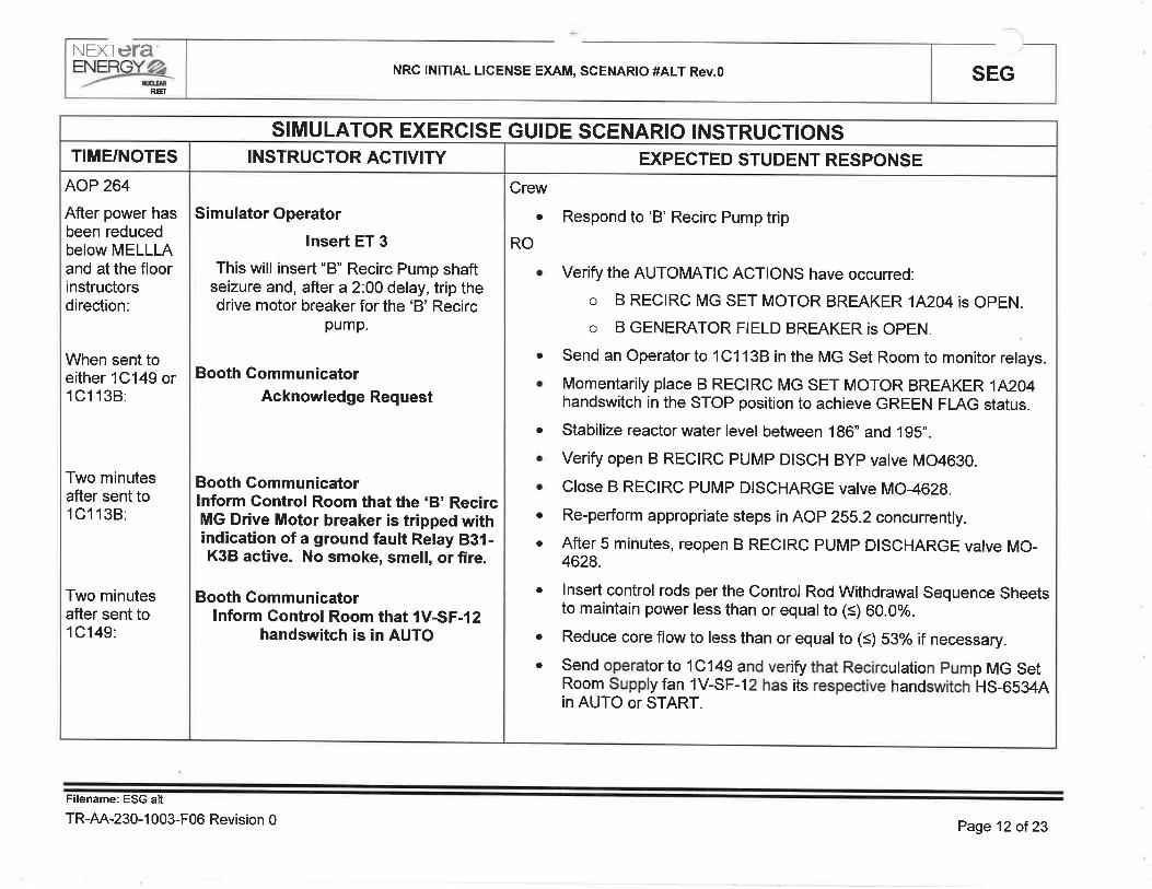
NEXIera*
ryyìLa_ NRC lNlTlAL LICENSE EXAM, SCENARIO #ALT Rev.O SEGffi
AOP 264
After power hasbeen reducedbelow MELLLAand at the floorinstructorsdirection:
When sent toeither 1C149 or1C1138:
Two minutesafter sent to1C1138:
Two minutesafter sent to1C149:
TIME/NOTES
s IMULATOR EXERCISE GUIDE SCENARIO INSTRUCTIONS
Simulator Operator
Insert ET 3
This will insert "B" Recirc Pump shaftseizure and, after a2.OO delay, trip thedrive motor breaker for the 'B' Recirc
pump.
Booth GommunicatorAcknowledge Request
Booth Gommunicatorlnform Control Room that the 'B' RecircMG Drive Motor breaker is tripped withindication of a ground fault Relay 831-K3B active. No smoke, smell, or fire.
Booth CommunicatorInform Control Room that 1V-SF-12
handswitch is in AUTO
INSTRUCTOR ACTIVITY
Crew
Respond to 'B' Recirc Pump tripa
RO
o Verify the AUTOMATIC ACTIONS have occurred:
o B RECIRC MG SET MOTOR BREAKER 1Ê204 is OpEN.
o B GENERATOR FIELD BREAKER is OPEN.
. send an operator to lc1138 in the MG set Room to monitor relays.
o Momentarily place B RECIRC MG SET MOTOR BREAKER 1Fü:O4handswitch in the STOP position to achieve GREEN FLAG status.
. Stabilize reactor water level between 186" and 195".
. Verify open B RECIRC PUMP DISCH BYP vatve MO4630.
. Close B RECIRC PUMP DISCHARGE vatve MO-4628.
. Re-perform appropriate steps in AOP 255.2 concurrenily.
. After 5 minutes, reopen B RECIRC PUMP DISCHARGE valve MO-4628.
o lnsert control rods per the control Rod withdrawal sequence sheetsto maintain power less than or equalto (s) 60.0%.
. Reduce core flow to less than or equal to (<) 53% if necessary.
. send operatorto 1c149 and verifythat Recirculation pump MG setRoom supply fan 1v-sF-12 has its respective handswitch HS-6534Ain AUTO or START.
EXPECTED STUDENT RESPONSE
F¡lename: ESG alt
TR-AA-230-1 003-F06 Revision 0 Page 12 oî 23

=Yæ"KNEXTETA'
NRC lNlTlAL LICENSE EXAM, SCENARIO #ALT Rev.0 SEG
AOP 264 Cont.:
When contactedas supportpersonnel:
TIME/NOTES
SIMULATOR EXERCISE GUIDE SCENARIO INSTRUCTIONS
Booth CommunicatorAcknowledge Request
INSTRUCTOR ACTIVITY
CRS
o Directs entering AOP 264 and reentering AOP 255.2.
. Directs and supervises reactivity manipulation to lower power below6Ù0/o.
. Comply with the Technical Specification requirements forRecirculation Loops Operating (3.4.1 Condition C)
EXPECTED STUDENT RESPONSE
Filename: ESG alt
TR-AA-230-1 003-F06 Revision 0 Page 13 of23

NEX|era"=yøø_ NRG lNlTlAL LICENSE EXAM, SCENARIO #ALT Rev.0 SEG
R.EÌ
CRD pumptrip/accumulatorTS
After Load Lineis below 1O0Vo,power has beenreduced -5olo,the TS has beenentered and atthe direction ofthe floorinstructor:
When contactedto investigateCRD pump andbreaker:
Two minutesafter request forCRD pump andbreaker status:
When contactedto investigatetheaccumulators:
Two minutesafter request foraccumulatorpressures:
TIME/NOTES
SIMULATOR EXERCISE GUIDE SCENARIO INSTRUCTIONS
Simulator Operatorlnsert ET 5
This will cause the'A' CRD pump to tripand accumulator lights to illuminate after a
time delay
Booth GommunicatorAcknowledge Request
Booth Gommunicatorlnform Gontrol Room that GRD pump is
warn to the touch/ GRD breaker hastripped on time delay overcurrent
Booth GommunicatorAcknowledge Request
Booth Gommunicatorlnform the control room 06-15, 34-35,38-l 9 accumulator pressures:
06-15 - 915 psig, 34-35 - 890 psig,38-19 - 935 psig
INSTRUCTOR ACTIVITY
Crew
Respond to'A' CRD pump trip and corresponding accumulator lights
RO
a
a
Send operator to check 1P-2094 breaker and to the pump for faultindications.
Start CRD Pump 1P-2098 per Ol 255 or Ol 255 QRC1.
o Verify adequate oil level in CRD Pump 1P-2098 motor andspeed changer.
o Close 1P-2098 Pump Discharge lsolation V-17-10 toapproximately 112 turn open.
o Adjust CRD SYSTEM FLOW CONTROL FC-1814 to 0 gpmin MANUAL.
o Verify MO-1833, INLET TO CRD RETURN LINE, is fuilyopen.
o Start CRD PUMP 1P-2098
o Slowly open Discharge lsolation V-17-10 to pressurizedownstream piping and to prevent CRD pump from trippingon low suction pressure.
o Vent both CRD Discharge Filters 1F-201{and B, using thefollowing Vent Valves:
o 1F-201A
. V-17-15 CRD Pump Disch Filter 1F-2014 Vent
. V-17-17 1F-201A Combined VenV Drain Line lsolation
a
EXPECTED STUDENT RESPONSE
Filename: ESG alt
TR AA 230-1003-F06 Revision 0 Page 14 of23

NEXTETA"
ryprk NRC lNlTlAL LICENSE EXAM, SCENARIO #ALT Rev.O SEG
CRD pumptrip/accumulatorTS Cont.:
When contactedto close V-17-10Trturn closed:
When contactedto openv-17-1Q.
When contactedto investigatetheaccumulatorsafter CRD pumpis started:
One minuteafter request foraccumulatorpressures:
lf contacted asRE to verifyslow rods:
Booth CommunicatorAcknowledge Request
Simulator OperatorWait I min and INSERT ET 7
This will insert RD04 to Tz openV-17-10
Booth CommunicatorAcknowledge Request
Simulator OperatorWait I min and INSERT ET 9
This will delete RD04 to fully open V-17-10
Booth GommunicatorAcknowledge Request
Booth Gommunicatorlnform the control room 06-15, 34-35,38-1 9 accumulator pressures:06-15 - 925 psig, 34-35 - 900 psig,
38-19 - 1100 psig
Booth Gommunicatorlnform control room that there are
currently no slow rods.
Respond to'A' CRD pump trip and corresponding accumulator lights
Start CRD Pump 1P-2098 per Ol 255 or Ol 255 QRC1. (Cont.)
o 1F-2018
. Y-17-18 CRD Pump Disch Filter 1F-2018 Vent
. Y-17-201F-2018 Combined VenV Drain Line lsolation
o Verify charging header pressurized > 1200 psig on pl-18164CHARGING WATER PRESSURE.
o Slowly adjust CRD SYSTEM FLOW CONTROL FC-1814 toobtain approximately 40 gpm on Fl-1814 CRD SYSTEMFLOW.
o When FC-1814 is properly controlling flow, then shift toAUTO.
o Slowly adjust DRIVE WATER nP CONTROL MO-1830 toobtain approximately 260 psid on PDt-1B2SA DRTVE WATER
^P.
o Directs starting the'B' CRD Pump
. Comply with the Technical Specification requirements for ControlRod Scram Accumulators (3.1.5 Condition B)
Crew
a
RO
a
CRS
Filename: ESG alt
TR-AA-230-1 003-F06 Revision 0 Page 15 of 23
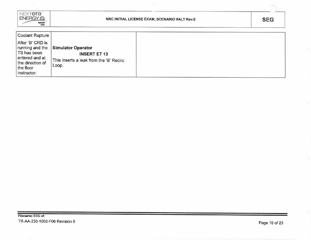
NEXTETA%3 NRC lNlTlAL LICENSE EXAM, SCENARIO #ALT Rev.O SEG
Coolant Rupture
After'B'CRD isrunning and theTS has beenentered and atthe direction ofthe floorinstructor:
Simulator Operator¡NSERT ET 13
This inserts a leak from the 'B' RecircLoop.
Filename: ESG alt
TR-AA-230-1 003-F06 Revision 0 Page 16 of23

NEXTETA"E:NryY2<-
,.- tflåaNRC lNlTlAL LICENSE EXAM, SCENARIO #ALT Rev.0 SEG
ffi
EOP 2
After DrywellPressureexceeds 2 psig:
lf contacted asplant personnelto deenergizeMO-2000:
One minuteafter ET 21 isactivated:
lf contacted toopen locallyopen MO-2000
Four minutesafter contactedto locally openM0-2000:
Booth CommunicatorAcknowledge Request
Simulator OperatorACTIVATE ET 21
This willturn off the lights on 1C03 for MO-2000 after a one minute delay.
Booth GommunicatorContact the Control Room and informthem that the breaker for MO-2000 is
open.
Booth CommunicatorAcknowledge Request
Simulator OperatorACTIVATE ET 27
Booth GommunicatorGontact the Gontrol Room and inform
them that MO-2000 is open.
Crew. lmplements the mitigation strategies of EOP 2, Primary Containment
Control
RO. lnforms the CRS of containment parameters including parameter name,
value and trend.o lnstalls Defeat 4.
o Utilizes Ol 149 QRC to spray the torus using 'A'side Torus Sprays.o Realizes that MO-2000 INBD DRYWELL SPRAY valve will not open and
HS-1903C ENABLE CONTAINMENT SPRAY VALVES will not function.o lnserts a manual reactor scram (CRITIGAL)
CRSo Enters into EOP 2 due to Drywell Pressure.o Obtains containment parameters.
o Directs installation of Defeat 4.o Directs spraying the torus after confirmation that torus pressure is greater
than 2 psig.
o Directs spraying the drywell before drywelltemperature reaches 280F.o Directs inserting a manual reactor scramr Placekeeps in EOP 2 to the applicable WAIT UNTTL steps in the pC/p
(PC/P-7) leg
Filename: ESG alt
ïR-AA-230-1 003-F06 Revision 0 Page17 of23
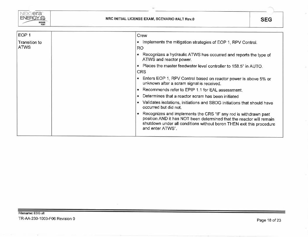
NEXIETA"
=Yæ4 NRC lNlTlAL LICENSE EXAM, SCENARIO #ALT Rev.O SEG
EOP 1
Transition toATWS
Crew. lmplements the mitigation strategies of EOP 1, RPV Control.ROo Recognizes a hydraulic ATWS has occurred and reports the type of
ATWS and reactor power.
r Places the master feedwater level controller to 158.S" in AUTO.CRSo Enters EOP 1, RPV Control based on reactor power is above So/o or
unknown after a scram signal is received.. Recommends refer to EPIP 1.1 for EAL assessment.o Determines that a reactor scram has been initiatedo Validates isolations, initiations and sBDG initiations that should have
occurred but did not.. Recognizes and implements the CRS "lF any rod is withdrawn past
position AND it has Nor been determined that the reactor will remainshutdown under all conditions without boron THEN exit this procedureand enter ATWS'.
Filename: ESG alt
TR-AA-230-1 003-F06 Revision 0 Page 18 of23

NEXTETA'NRC lNlTlAL LICENSE EXAM, SCENARIO #ALT Rev.0 SEG
ATWS Cont.
When directedto install Defeat12:
Simulator Operator
AGTIVATE ET 23
This will place Remote Functions RP02 inTEST after a time delay; to install Defeat
12.
When RP02 is inserted, callthe controlroom and inform them that Defeat 12 is
complete.
Crew. lmplements the actions of ATWS.RO. Locks out ADS. (CRlTlcAL). Gompletes the ATWS QRC. Reports completion and includes SBLC
availability, ARI success, reactor power and RPV level.. lnstalls Defeat 11.. lnjects SBLC. Reports completion and includes reactor power and RPV
level.. Coordinates performance of the Hydraulic ATWS RlPs. (CRITICAL). lnstalls Defeat 4o Verifies ortrip/lockout HPCI.. Terminates injection:
. Condensate and Feed:. Close Feedwater Regulating Valves CV-1579, CV-1621, CV-1622
as follows:. Take MANUAL control of Master Fed Reg Valve Auto/Man
Control LC-4577 and dialthe controller down until all FeedwaterRegulating Valves indicate closed as indicated on:o HC-1579, A Feed Reg Valve Manual/Auto Transfer. HC-1621, B Feed Reg Valve Manual/Auto Transfero HC-1622, Startup Feed Reg Valve Manual/Auto Transfer
. RHR:. Place MO-2004 and/or MO-1904 LPCI OPEN INTLK OVERRIDE
HS-2004C and/or HS-1904C to OVERRIDE¡ When 1C038 (B-5) RHR RX LO PRESSURE PERMISSIVE AT
450 PSIG is activated, close MO-2004[MO-1904] by taking HS-2004[HS-1904]to CLOSE
Filename: ESG alt
TR-AA-230-1 003-F06 Revision 0 Page 19 of23

NEXTETANRC lNlTlAL LICENSE EXAM, SCENARIO #ALT Rev.0 SEG
ATWS
ATWS Cont.
Crew. lmplements the actions of ATWS.RO
. Reports reactor power at87" and lowering.
. Reports RPV level when reactor power is less than 5% or when 15" isreached.
. Secures RCIC when RPV level is under control.
. 1C05 operator assumes the front panel RlPs after RPV level is undercontrol.
CRSo Directs reporting reactor power at87" and lowering.. Directs RPV level continue to be lowered until reactor power is less than
5o/o or RPV level reaches 15".
o Directs RPV level control band of -25" to either 15" or the RPV levelwhen reactor power was 5% with condensate and feedwater.(cRrTrcAL)
CRSo Directs locking out ADS.o Directs the ATWS QRC be completed.o Directs Defeat 11 installation.o Directs injection of SBLC.. Directs performance of Hydraulic RIPS including installation of Defeat 12.o Directs power level control mitigation strategies.o Directs inserting Defeat 4.. Directs Terminate/prevent injection from HPCI, Condensate/Feedwater,
Core Spray and RHR. (cRlTlCAL)
Filename: ESG alt
TR-AA-230-1 003-F06 Revision 0 Page2O of 23

NEXTETA"
=Yry NRC lNlTlAL LICENSE EXAM, SCENARIO #ALT Rev.O SEG
When RPV levelis beingrestored, thecrew isprogressing toSDC, and at thedirection of theFloor lnstructor:
ATWSTransition toEOP 1
After all rodshave inserted.
Simulator Operator
Place the simulator in FREEZE.
Floor lnstructor
Announce the scenario is complete;please stand by your stations and do
not discuss the scenario with yourcrew.
Floor lnstructorMonitor and ensure that crew monitorspressure during re-flood of the RPV.Grew should limit injection to ensurecooldown limits are not violated.
Crew. When all rods are in, transition from ATWS to EOP 1
RO. Reports that all rods in after performing Scram-Reset-Scram. Secures SBLCo Controls level 170"-211" using Condensate and Feedwater
CRS. Confers with the SM on the transition to ATWS.. Directs securing SBLC injectiono Directs RPV level 170"-211" using Condensate and Feedwater
Filename: ESG alt
TR-AA-230-1 003-F06 Revision 0 Page21 of23

SEGNRC lNlTlAL LICENSE EXAM, SCENARIO #ALT Rev.ONEXTETA"EYærc-
QUANTITATIVE ATTRI BUTESMalfunctions:
Before EOP Entry:
1. 'B' Recirc Pump 20o/o runback
2. Recirculation pump trip
3. CRD pump trip
4. Accumulator fails to recharge
After EOP Entry:
1. 'A' side containment enable switch fails to operate
2. 'B' side lnboard Drywell Spray valve (MO-2000) fails to open
Abnormal Events:
1. AOP 255.2
2. AOP 264
Maior Transients:
1. LOCA
2. ATWS
Gritical Tasks:
#21 lF the reactor is operating at power and Drywell temperature is rising, THEN insert a
manual scram before drywell temperature reaches 280'F. {BWROG PC 4.1}
#4: lF a scram is required and Reactor power is above 5%, THEN reduce power below 5%using one or more of the following methods: {BWROG RPV 4.1, 5.1, 6.1}
lnserting control rods using RlPs lnjection of Boron
#6: lF a reactor scram is required and the reactor is not shutdown under all conditions, THENlockout ADS before automatic actuation. {BWROG RPV 4.2,5.2,6.21
#10: lF a reactor scram is required, and reactor power is >5%, and Power/level control isrequired, THEN terminate and prevent injection until conditions allow reinjection. {BWROGRPV 6.3)
#11 lF performing ATWS Power/level control and Conditions are met to allow reinjection,THEN crew actions are taken to maintain RPV level above -25" by injecting using Table 1B
systems. {BWROG RPV 6.4}
Filename: ESG alt
TR-AA-230-1 003-F06 Revision 0 Page 22 of 23

SEGNRC lNlTlAL LICENSE EXAM, SCENARIO #ALT Rev.ONEXTETA-,Yær6.
CREW GRADING ATTACHMENT
ESG ALT Rev. 0 Date
B.O.P
1C03
1C05
STA
CRS
OSM
EvaluatorPositionOperator Name
Management Representative/Lead Evaluator
Crew Critical Tasks
I
5. lF performing ATWS Power/level control and Conditions are met toallow reinjection, THEN crew actions are taken to maintain RPV levelabove -25" by injecting using Table 1B systems.
4. lF a reactor scram is required, and reactor power is >5%, andPower/level control is required, THEN terminate and prevent injectionuntil conditions allow reinjection.
3. lF a reactor scram is required and the reactor is not shutdown under allconditions, THEN lockout ADS before automatic actuation,
2. lF a scram is required and Reactor power is above 5%, THEN reducepower below 5% using one or more of the following methods:
lnjection of Boron
lnserting control rods using RlPs
1. lF the reactor is operating at power and Drywell temperature is rising,THEN insert a manual scram before drywelltemperature reaches280.F.
UNSATSATTask Statement
Filename: ESG alt
TR-AA-230-1 003-F06 Revision 0 Page 23 of 23

STP
Page
Rev.
3.4,2-01
1of2236
SURVEILLANCE TEST PROCEDURE
TITLE: DAILY JET PUMP OPERABILIWTEST
DAECDUANE ARNOLD ENERGY CENTER
Usage Level:
CONTINUOUS
Record the following: Date / Time I lnitials:
NOTE: lJser shatt pe¡form and document a Temp lssue / Rev. Check to ensure revision iscurrent, in accordance with procedure use and adherence requirements.
Prepared By: Date:
Print Signature
Approved By I Date
Print Signature
PROCEDURE APPROVAL
I
Reviewed By: I Date:
Print Signature
Reviewed By: I Date:
Print Signature
cRoss-DrscrPLlNE REVIEW (AS REQUIRED)

STP
Page
Rev.
3.4.2-01
2of2236
SURVEILLANCE TEST PROCEDURE
TTTLE: DAILY JET PUMP OPERABILIWTEST
DAECDUANE ARNOLD ENERGY CENTER
r.0
1.1
1.2
1.3
2.0
2.1
PURPOSE
The purpose of this STP is to log Recirc Pump speeds daily to ensure Recirc Pumps are notoperating at a significant speed mismatch and to verify Jet Pump operability. Verification ofJet Pump operability shall be made daily, following startup of a Recirculation Pump, and afterany unexplained changes in core flow, Jet Pump Loop flow, Recirc Loop flow, or core plate
differential pressure.
When this procedure is performed in its entirety it FULLY SATISFIES Recirculation LoopOperations Recirc Pump speed mismatch surveillance requirements.
When this procedure is performed in its entirety it FULLY SATISFIES Jet Pumps surveillancerequirements.
BRIEFING INFORMATION
PERFORMANCE I NFORMATION
2.1.1 This STP is organized as follows:
Jet Pump Trending Data7.4
Jet Pumps 1-8 Operability Check7.3
Jet Pumps 9-16 Operability Check7.2
Recirc Pump Speed Mismatch Check7.1
EvolutionSTP Sections
All steps within a section are to be performed in sequence and the STP steps carriedthrough to completion, unless otherwise indicated. The sections may be performedconcurrently for ease of recording data.
Sections 7 .2 and 7 .3 are not required to be performed when reactor power is less than orequal to (<) 21.7% RTP. lf this procedure is being performed when reactor power is lessthan or equal to (<) 21.7% RTP, Prerequisite 6.2 and Sections 7.2 and 7 .3 are to be marked"N/4".
2.1.2 Personnel recommended to perform this procedure
1 Operations
Special Test Equipment required:
None
2.1.3
2.1.4 lf Recirculation Pump speed is less than 60% of rated, an Engineering evaluationmay be performed to determine Jet Pump OPERABILITY.
Collect Jet Pump DP values using the "2 MIN AVE" screen on FR-4501 andFR-4502 in Sections 7.2,7.3, andT.4. Any display screen can be used at othertimes.
2.1.5

STP
Page
Rev.
3.4.2-013of2236
SURVEILLANCE TEST PROCEDURE
TITLE: DAILY JET PUMP OPERABILITYTEST
DAE,CDUANE ARNOLD ENERGY CENTER
2.2
2.3
3.0
3.1
4.0
4.1
4.2
4.3
5.0
5.1
GENERAL CAUTIONS
2.2.1 None
SPECIAL PRECAUTIONS
2.3.1 None
REFERENCES
None
GENERAL INSTRUCTIONS
Steps marked with a "TS" immediately to the right of the step sign-off line are required by
Technical Specifications. lf these steps do not meet their acceptance criteria or cannot beperformed, a NRC reportable condition may exist and shall be reported to the Control RoomSupervisor (CRS) immediately.
The CRS shall be immediately notified and the appropriate Limiting Condition for Operationssection of Technical Specifications referred to whenever problems are encountered during theperformance of this STP.
An Action Request (AR) should be completed for any problems encountered with "TS" markedsteps during the performance of this test.
APPENDICES
Appendix A - JETS Program lnstructions

Sheet 1 o'f 1JETS PROGRAM INSTRUCTIONSAppendix A
STP
Page
Rev.
3.4.2-01
4of2236
SURVEILLANCE TEST PROCEDURE
TITLE: DAILY JET PUMP OPERABILITYTEST
DAE,CDUANE ARNOLD ENERGY CENfER
1. lf at a workstation desktop with access to PPC, log in to PPC as follows:a. Click the Windows icon in the lower left corner of the screen.b. Click Computer: OSDisk (C:): Program Files (x86): Reflection: User: PPC.
c. At Username Prompt, type SSE <Enter>.
d. At Password Prompt, enter the appropriate password and press <Entep. Note thatthe program will not display any characters, nor will the cursor move, while enteringthe password.
e, At the $ prompt, type JETS and press <Enter>.
The Jet Pump Program main menu should come up on the screen.
2. lf at a VAX/PPC terminal, log onto SSE as follows:a. Log onto the SSE account.b. At the PPCI-SSE prompt, type JETS and press <Enter>. The Jet Pump program
main menu should come up on the screen.
3. Type I to access combined Loop A and Loop B Jet Pump tables. Type 2 to access onlythe Loop A Jet Pump table (Jet Pumps 9-16). Type 3 to access only the Loop B JetPump table (Jet Pumps l-8).
NOTE
All ÂPs must be a positive value between 0 and 30, but not including 0 (0<lP<30). The program
will automatically tab forward as each Jet Pump's AP is entered. The <Tab> key may be used tomove forward to the next Jet Pump, if desired. The <Control> and <H> keys pressed
simultaneously may be used to move backward to the previous Jet Pump, if desired. lf desired to
change a ÂP, use the <Backspace> key to erase all numerals to the left of the decimal pointbefore entering the new numbers.
4. Type in each Jet Pump's AP
NOTE
lf all fields are not filled with a positive number between 0 and 30, but not including 0 (0<AP<30)when Step 5.0 is performed, the program will not calculate the % deviations and will return to theJet Pump main menu.
5. Press the <Enter> key to calculate the % deviations. The printout will automatically print
on laser printer LTA14 and the program will automatically terminate.

INITIALSPerformance Date:Prerequisites
STP
PageRev.
3.4.2-01
5of2236
SURVEILLANCE TEST PROCEDURE
TITLE: DAILY JET PUMP OPERABILIWTEST
DAECDUANE ARNOLD ENERGY CENTER
6.0
6.1
PREREQUISITES
The reactor is in two-loop operation. (lf the reactor is in single loopoperation, perform STP 3.4,2-03 instead.)
For sectionsT.2 and 7.3, reactor power is greater than (>) 21'7%RTP(See Performance lnformation Step 2.1.1.)
(oPS)
6.2(oPS)

INITIALSPerformance Date:
STP
Page
Rev.
3.4.2-01
6of2236
SURVEILLANCE TEST PROCEDURb
TITLE: DAILY JET PUMP OPERABILITYTEST
DAE,CDUANE ARNOLD ENERGY CENTER
7.0
7.1
PROCEDURE
RECIRC PUMP SPEED MISMATCH CHECK
7.1,1 At 1C04, on SIC-92454, A MG SET SPEED CONTROL, perform
the following:
a. Use the "D" button to select "X" - PERCENT SPEED andrecord the value:
A MG SET PERCENT SPEED (SlC-92454'X)
-%o
b. Use the "D" button to select "S" - SETPOINT.
7.1.2 At 1C04, on SIC-92458, B MG SET SPEED CONTROL, perform
the following:
a. Use the "D" button to select "X" - PERCENT SPEED andrecord the value:
B MG SET PERCENT SPEED (SlC-92458.X)
-Yo
b. Use the "D" button to select "S" - SETPOINT.
7 .1.3 On Figure 1, plot the intersection of the Recirc Pump speedvalues using the data recorded in Steps 7.1.1.a and 7 .1'2'a.
7.1.4 Confirm that the point plotted on Figure 1 is within the appropriatelimit for the current core power. lf the point is outside the limit,immediately notify the CRS,
(PRTNT / SrGN)
Performed by: Date: Time: lnit
TS
TS
TS
I
I
I

Sheet 1 of 1SPEED OF PUMP ''4"
vs. SPEED OF PUMP "B"Figure 1
STP
Page
Rev.
3.4.2-01
7of2236
SURVEILLANCE TEST PROCEDURE
TITLE: DAILY JET PUMP OPERABILITYTEST
DAE,COUANE ARNOLD ENERGY CENTER
OUTSIDELIMIT
CONDITIONS
Y
\ NNK) S// x
sv <<CONDITIONS
OUTSIDELIMIT
\yYY\\
\\N /
N\\N
LIMITBELOW69.4o/o
POWER
LIMITABOVE ORUAL TO 69.4o/o
POWER
sot¡JIJJÀ|t,À=fÀ
f
110
100
90
80
70
60
50
40
30
20
10
0
0 10 20 30 40 50 60 70 80 90 100 110
"8" PUMP SPEED (%)

INITIALSPerformance Date:
STP
Page
Rev.
3.4.2-018of2236
SURVEILLANCE TEST PROCEDURE
TITLE: DAILY JET PUMP OPERABILIWTEST
DAECDUANE ARNOLD ENERGY CENTER
7.2 JET PUMPS 9-16 OPERABILITY CHECK
7.2.1 At 1C04, record the following data for the "4" Recirc Pump:
A MG SET PERCENT SPEED (S|C-92454.X from Step 7.1.1.a)%
DTSCHARGE FLOW (Fl-4634A)
LOOP A FLOW (FR-4503, Ch 1)
KGPM
Mlbm/hr
7.2.2 Using the data recorded in Step 7.2.1, plot "A" Recirc MG Setspeed vs, "4" Recirc Pump discharge flow on Figure 2.
Using the data recorded in Step 7.2.1, plot "4" Recirc MG Setspeed vs. Loop "A" Jet Pump flow on Figure 3.
NOTElf Step 7.2.4.a is answered NO, Acceptance Criteria Step 8.2.2 should beanswered YES !f either Step 7.2.8.a or Step 7 .2.8.e is answered YES.
7.2.4 Perform the following evaluation
a. Are all of the points that were plotted on Figure 2 and Figure 3
between or on the sloped lines?
(YES/NO)
b. lf the answer to Step 7.2.4.a was YES, Jet Pumps 9-16 areOPERABLE. "N/A" the remainder of Section T.2 and Figure 4.
c. lf the answer to Step 7.2.4.a was NO, immediately notify theCRS.
7.2.5 lf the JETS program is available, obtain a printout of "4" RecircLoop AP's using the instructions provided in Appendix "A".
a. Attach the printout to the STP.
TS
7.2.3 TS
TS

INITIALSPerformance Date:
STP
Page
Rev.
3.4.2-01
9of2236
SURVEILLANCE TEST PROCEDURE
TITLE: DAILY JET PUMP OPERABILITYTEST
DAECDUANE ARNOLD ENERGY CENTËR
7.2.6 lf the JETS program is NOT available, perform the following
a. At 1C38 recorder FR-4501 Jet Pump Flow - Loop A, using the"2 MIN AVE" screen record the indicated RECIRC LOOP AJet Pump differential pressure value for each Jet Pump incolumn "4" of Table A (contained in Step 7,2.6.d).
b. Calculate the sum of the individual Jet Pump ÂPs and theaverage Jet Pump AP and record those values in theappropriate spaces at the bottom of Table A.
c. Calculate the difference between each individual Jet Pump aPand the average AP and record the results in column "8" ofTable A.
d. Using the following equation, calculate the percent deviationof each individual Jet Pump aP from the average
^P, and
record the result in column "C" of Table A.
% Deviation = 100 xlnd, AP - Avg. lP
Avg. lP
TABLE AA
(^P)
B
(lnd.AP - Avg.nP)
c(% Deviation)JET PUMP
JP-9
JP-I O
JP-11
JP.12
JP-13
JP-14
JP.15
JP-16
(Sum of APs) (Avs. aP)
Plot each individual Recirc Loop "4" Jet Pump % deviation value(from column "C" of Table A or JETS program calculation) onFigure 4.
I
7.2.7

INITIALSPerformance Date:
STP
Page
Rev.
3.4.2-01
10 of 22
36
SURVEILLANCE TEST PROCEDURb
TITLE: DAILY JET PUMP OPERABILITYTEST
DAECDUANE ARNOLD ENERGY CENTER
NOTElf Step 7.2.8.a is answered NO, Acceptance Criteria Step 8.2.2 shall be answeredNO also, unless Recirc Pump speed is less than 60% of rated and an Engineeringevaluation determines that the Jet Pumps are OPERABLE.
7.2.8 Perform the following evaluation
a. Are all of the points plotted on Figure 4 on or between thelines of the allowable band?
(YES/NO)
b. lf the answer to Step 7.2.8.a is YES, Jet Pumps 9-16 areOPERABLE. "N/A" Steps 7.2.8.c, 7.2.8.d, and T.2.8.e.
c. lf the answer to Step 7.2.8.a is NO and Recirc Pump speed is
greater than or equalto (>) 60% of rated, immediately notifythe CRS. Then, "N/4" Steps 7.2.8.b,7.2.8.d, andT.2.8.e.
d. lf the answer to Step 7.2.8.a is NO and Recirc Pump speed isless than (<) 60% of rated, immediately inform the CRS andthen contact Engineering to perform an evaluation of JetPump operability. Then, "N/4" Steps 7.2.8.b andT.2.8.c.
TS
e. lf an Engineering evaluation was performed, are JetPumps 9-16 OPERABLE? ("N/A" if an Engineering evaluation Engineering
is not required to be performed.)
(YES/NO)
(PRTNT / S|GN)
I
TS
I
IPerformed by: Date Time: lnit.

Sheet 1 of 1''A'' MG SET SPEED
vs. "4" RECIRC PUMP DISCHARGE FLOWFigure 2
STP
Page
Rev.
3.4.2-01
11 of 22
36
SURVEILLANCE TEST PROCEDURE
TITLE: DAILY JET PUMP OPERABILIWTEST
DAE,CDUANE ARNOLD ENERGY CENTER
TWo Loop Operation",4," Recirc Pump Flow Curve
\O \O 1O 1O 1O \Ò \O 1O \OO\ O\ O\ O\ O\ O\ O\ O\ O\c)ra)c)lr)C)\ñotñoIt*tt*OOoOO\O\OOÊ ÊÊÊ
MG Set Speed (%)
35.0
30.0
2s.0
20.0
.0
.0
5.0
0
à*vo
tJrc)b0L(g
o(^na.E
I
1
5
0
0rO \O rO \O \O 1O 1O6\ o\ O\ O\ O\ O\ O\Alr)Otr)Ot.)Oc-l C.l cQ cf) t .+ tr)
lr)lr)
o\a\o\Ôo\ìô\o
j
i
i
(iI
II
lI't'II
i
lI
l
I/
i
.1.
I
x
1/irl
l
I
iIII
f
4
I
I
I
I
iII
i
Last updated from data acquired on November 1-4,2016

Sheet 1 of 1''A'' MG SET SPEED
vs. LOOP "4" JET PUMP FLOWFigure 3
STP
Page
Rev.
3.4.2-0112 of 22
36
SURVEILLANCE TEST PROCEDURE
TITLE: DAILY JET PUMP OPERABILIWTEST
DAE,CDUANE ARNOLD ENERGY CENTER
I
1
Ttvo Loop OperationJet Pump Loop "4" Flow
\o .O rO :ô rO \O \O rO \Oo\ o\ o\ o\ 6\ o\ 6\ ê\ O\Olr)Olr)Otr)AìôONc.ìc.)cos+tr)tô\o
MC Set Speed (%)
30.0
25.0
20.0
15.0
I
tiPTr
I¿
ot¡r
aoJ
0.0
5.0
0 .0\oo\(r)\o
1Oo\
t-r
\oÕ\|r)t--
\O \O 1Ô 1O 1O \O \OO\ O\ O\ O\ O\ O\ O\AtnO\r)Olr)Ooooêo\ooo ÊÊ-
Last updated from data acquired on November 1-4, 2016

Sheet 1 of 1LOOP ''A'' JET PUMP % DEVIATION
vS. JET PUMP NUMBERFigure 4
STP
Page
Rev.
3.4.2-01
13 oî 22
36
SURVEILLANCE TEST PROCEDURE
TITLE: DAILY JET PUMP OPERABILIWTEST
DAECDUANE ARNOLD ENERGY CENTER
TWo Loop OperationLoop ttA" Jet Pump Dp o/o Deviation
30.0%
20.0%
10.0%
cd
()âa.âa.
*(,)
0.0%
1 0 .0o/o
-20.0%
-30.0%9 10 ll t2 13
Jet Pump Number
14 15 16
a\\
./\
\ /\,/\
,/\./\./\./
-
\./\
Last updated from data acquired on November 1-4, 2016.

INITIALSPerformance Date:
STP
Page
Rev.
3.4.2-01
14 of 22
36
SURVEILLANCE TEST PROCEDURE
TITLE: DAILY JET PUMP OPERAB¡LIWTEST
DAECDUANE ARNOLD ENERGY CENTER
7.3 JET PUMPS 1-8 OPERABILITY CHECK
7 .3.1 At 1C04, record the following data for the "8" Recirc Pump:
B MG SET PERCENT SPEED (SlC-92458.X from Step 7.1.2.a)o/o
DTSCHARG E FLOW (Fl-46348) KGPM
LOOP B FLOW (FR-4504, Ch 1) Mlbm/hr
7.3.2 Using the data recorded in Step 7.3.1, plot "8" Recirc MG Setspeed vs. "8" Recirc Pump discharge flow on Figure 5.
Using the data recorded in Step 7.3.1, plot "8" Recirc MG Setspeed vs. Loop "B" Jet Pump flow on Figure 6.
NOTElf Step 7.3.4.a is answered NO, Acceptance Criteria Step 8,2.3 should beanswered YES jI either Step 7.3.8.a or Step 7.3.8.e is answered YES.
7.3.4 Perform the following evaluation
a. Are all of the points that were plotted on Figure 5 and Figure 6between or on the sloped lines?
(YES/NO)
b. lf the answer to Step 7.3.4.a was YES, Jet Pumps 1-8 areOPERABLE. "N/4" the remainder of Section 7.3 and Figure 7
c. lf the answer to Step 7.3.4.a was NO, immediately notify theCRS.
7.3.5 lf the JETS program is available, obtain a printout of "8" RecircLoop AP's using the instructions provided in Appendix "A".
a. Attach the printout to the STP.
TS
7.3.3 TS
TS

INITIALSPerformance Date
STP
Page
Rev.
3.4.2-01
15 of 22
36
SURVEILLANCE TEST PROCEDURE
TITLE: DAILY JET PUMP OPERABILITYTEST
DAE,CDUANE ARNOLD ENERGY CENTER
7.3.6 lf the JETS program is NOT available, perform the following
a. At I C38 recorder FR-4502 Jet Pump Flow - Loop B, using the"2 MIN AVE" screen record the indicated RECIRC LOOP B
Jet Pump differential pressure value for each Jet Pump in
column "4" of Table B (contained in Step 7.3.6.d).
b. Calculate the sum of the individual Jet Pump APs and theaverage Jet Pump
^P and record the results in the
appropriate spaces at the bottom of Table B.
c. Calculate the difference between each individual Jet Pump AP
and the average AP and record the result in column "8" ofTable B.
d. Using the following equation, calculate the percent deviationof each individual Jet Pump ÂP from the average ÁP and thenrecord the result in column "C" of Table B.
% Deviation = 100 xlnd. AP - Avg.
^PAvg. lP
TABLE BB
(lnd.ÂP - Avg.AP)
A
(^P)
c(% Deviation)JET PUMP
JP-1
JP-2
JP-3
JP-4
JP-5
JP-6
JP-7
JP-8
(Sum of ÂPs) (Avs. ÂP)
Plot each individual Recirc Loop "8" Jet Pump % deviation value(from column "C" of Table B or JETS program calculation) onFigure 7.
I
7.3.7

INITIALSPerformance Date:
STP
Page
Rev.
3.4.2-01
16 of 22
36
SURVEILLANCE TEST PROCEDURE
TITLE: DAILY JET PUMP OPERABILITYTEST
DAECDUANE ARNOLO ENERGY CENTER
NOTElf Step 7.3.8.a is answered NO, Acceptance Criteria Step 8.2,3 shall be answeredNO also, unless Recirc Pump speed is less than 60% of rated and an Engineeringevaluation determines that Jet Pumps are OPERABLE.
7.3.8 Perform the following evaluation
a. Are allof the points plotted on Figure 7 on or between thelines of the allowable band?
(YES/NO)
b. lf the answer to Step 7.3.8.a is YES, Jet Pumps 1-8 areOPERABLE. "N/4" Steps 7.3.8.c, 7.3.8.d, and 7.3.8,e.
c. lf the answer to Step 7.3.8.a is NO and Recirc Pump speed isgreater than or equal to (>) 60% of rated, immediately notifythe CRS. Then, "N/4" Steps 7.3.8.b, 7.3.8.d, and 7.3.8.e.
d. lf the answer to Step 7.3.8.a is NO and Recirc Pump speed isless than (<) 60% of rated, immediately inform the CRS andthen contact Engineering to perform an evaluation of JetPump operability. Then, "N/4" Steps 7.3.8.b and 7.3.8.c.
e. lf an Engineering evaluation was performed, are Jet Pumps1-8 OPERABLE? ("N/4" if an Engineering evaluation is notrequired to be performed.)
(YES/NO)
(PRTNT / SrGN)
I
Performed by: Date: Time lnit.
TS
TSEngineering
I
I

Sheet 1 of 1''B'' MG SET SPEED
vs. "8" RECIRC PUMP DISCHARGE FLOWFigure 5
STP
Page
Rev.
3.4.2-0117 of 22
36
SURVEILLANCE TEST PROCEDURE
TITLE: DAILY JET PUMP OPERABILITYTEST
DAECDUANE ARNOLO ENERGY CENTER
Tïvo Loop Operation"8" Recirc Pump Flow Curve
1O \O 1O 1O \o \O \Oo\ o\ o\ o\ e\ o\ o\O(ôOtr)O(.)Oc.tôìcî catsl.)
35.0
30.0
25.0
à
Yzo
llroboLcË
ts lst-l9.EÀ
10.0
5.0
0
.0
o\|r)lr)
1O 1O 1O 1O 1O 1O 1O 1O \O \O 1O
Otr)OIr)Otr)O|r)OIñO\O\OFtr-oOoOO\O\OOÊ-Ê
MG Set Speed (%)
4
T
i
L
I4
l
I
i
i
-ii
)/I
I
I.
i
0.0
Last updated from data acquired on November 1-4, 2016

Sheet 1 of 1''B'' MG SET SPEED
vs. LOOP "8" JET PUMP FLOWFigure 6
STP
Page
Rev.
3.4.2-01
18 of 22
36
SURVEILLANCE TEST PROCEDURE
TITLE: DAILY JET PUMP OPERABILIryTEST
DAECDUANE ARNOLD ENERGY CENTER
I
I
I
I
tlt1t1
I
I
l
l
Iì
I
Iilll
VtviìÌ
tI
I
l
L
i
i
l
'f
..i.
l
i
I
I-îI
i
/I
L
I
II
)t i!Ail
I.-t
lili
¡
iili/
Y)
,II
I
ll
i
i
Il
I
I
IrliiiI
iI
l
l
brIl
l
Ill
L
Lli¡'i
I
I
I
I
I
I
I
I
i
l
I
tliltlitil
I
l
ill
i
Iit y,
L
ì
i
!!ii-
ii¡I
I
I
iI
i:l
TWo Loop OperationJet Pump Loop "8" Flow
1O \O \O 1O \O 1O 1O \OO\ O\ O\ O\ Ò\ O\ O\ ô\OTôOlr)Olr)O'.r)õ¡c.ìc.lcî +$(r)tr)
MG Set Speed (%)
30.0
2s.0
20.0
15.0
10.0
5.0
r+IäIfJr
maoo¡
\o
1O^\(r)\o
6\
t-*
1Oo\lr)t*r
o\ o\ o\ o\ o\ o\ o\olr)olr)o\ñ<>ooooO.O'OO *
0.0
Last updated from data acquired on November 1-4, 2016

Sheet 1 of 1LOOP ''8" JET PUMP % DEVIATION
vs. JET PUMP NUMBERFigure 7
STP
Page
Rev.
3.4.2-01
19 of 22
36
SURVEILLANCE TEST PROCEDURE
TITLE: DAILY JET PUMP OPERABILIWTEST
DAE,CDUANE ARNOLD ENERGY CENTER
T\vo Loop OperationLoop t'8" Jet Pump Dp o/o Deviation
30.0%
20.0%
10.0%
(B
c)
at-la
À(.)
0 .0%
I 0 0%
-20.0%
-30.0%1 2 J 45
Jet Pump Number
6 7 8
./\.a\
./\\
7/\/./\
/./\/\./\
/\/\
\
Last updated from data acquired on November 1-4, 2016.
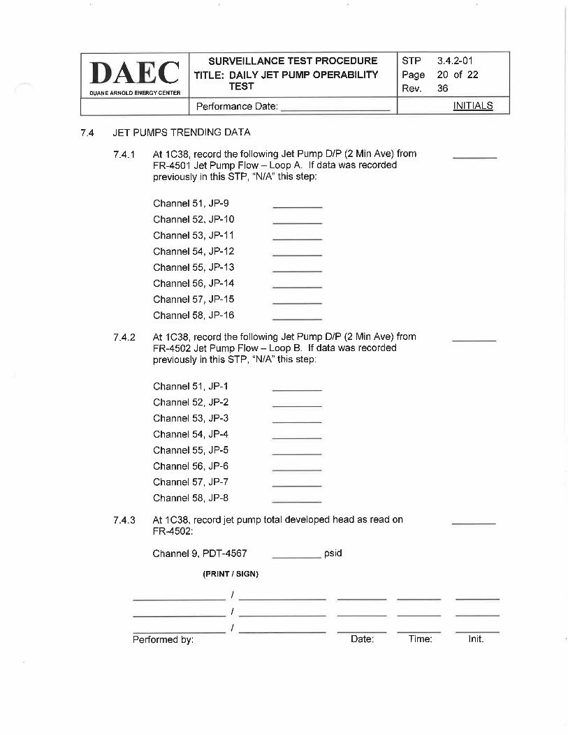
INITIALSPerformance Date
STP
Page
Rev.
3.4.2-01
20 of 22
36
SURVEILLANCE TEST PROCEDURE
TITLE: DAILY JET PUMP OPERABILITYTEST
DAECDUANE ARNOLD ENERGY CENTER
7.4 JET PUMPS TRENDING DATA
7 .4.1 At 1C38, record the following Jet Pump DIP (2 Min Ave) fromFR-4501 Jet Pump Flow - Loop A. lf data was recordedpreviously in this STP, 'N/A'this step:
Channel 51, JP-g
Channel 52, JP-10
Channel 53, JP-1 1
Channel 54, JP-12
Channel 55, JP-13
Channel 56, JP-14
Channel 57, JP-15
Channel 58, JP-16
7.4.2 At 1C38, record thefollowing Jet Pump DIP (2 Min Ave) fromFR-4502 Jet Pump Flow - Loop B. lf data was recordedpreviously in this STP, 'N/4" this step:
Channel 51, JP-1
Channel 52, JP-2
Channel 53, JP-3
Channel 54, JP-4
Channel 55, JP-5
Channel 56, JP-6
Channel 57, JP-7
Channel 58, JP-8
7.4.3 At 1C38, record jet pump total developed head as read onFR-4502:
Channel I, PDT-4567
(PRTNT / S|GN)
psid
I
I
Performed by: Date Time: lnit.

INITIALSPerformance Date
STP
Page
Rev.
3.4.2-01
21 of 22
36
SURVEILLANCE TEST PROCEDURE
TITLE: DAILY JET PUMP OPERABIUryTEST
DAE,CDUANE ARNOLD ENERGY CENTER
8.0
8.1
8.2
8.3
ACCEPTANCE CRITERIA
Check below the reason for performing this STP. lf this STP is performedfor any reason other than for satisfying the PURPOSE as stated inSection 1.0, indicate below (otherwise mark this step "N/4"):
Daily Requirement
Pump Start
Unexplained changes
Other
All Technical-Specification-required items, as indicated by "TS", have beenperformed satisfactorily.
8.2.1 Section 7.1 ( ) YES ( ) NO + CRS notified
8.2.2 Section 7.2 ( ) YES ( ) NO + CRS notified
8.2.3 Section 7.3 ( ) YES ( ) NO =+ CRS notified
All other items checked in this test have been performed satisfactorily.
8.3.1 Section 7.1 ( )YES ( ) NO = CRS notified
8.3.2 Section 7.2 ( ) YES ( ) NO + CRS notified
8.3.3 Section 7.3 ( ) YES ( ) NO + CRS notified
8.3.4 Section 7.4 ( ) YES ( ) NO + CRS notified
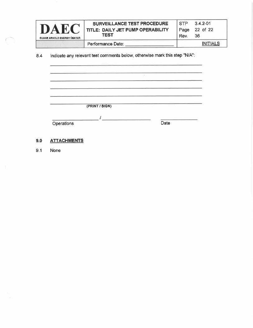
INITIALSPerformance Date:
STP
Page
Rev.
3.4.2-01
22 of 22
36
SURVEILLANCE TEST PROCEDURE
TITLE: DAILY JET PUMP OPERABILIWTEST
DAECDUANE ARNOLD ENERCY CENTERf--\'
8.4 lndicate any relevant test comments below, otherwise mark this step "N/4":
/ srGN)
IOperations
ATTACHMENTS
None
Date
9,0
9.1


![T ovu] M 14 2, SIMULATrING1o84 MT ovu]J MEMOR&NDA. LOCT. Iz, Igox, results enhanced pleasure in the taking of all foods, rich and simple, andespecially in the appreciation of good](https://static.fdocuments.net/doc/165x107/60d5cca65f782c7e9868c0df/t-ovu-m-14-2-simulatring-1o84-mt-ovuj-memornda-loct-iz-igox-results.jpg)


