OTC 24015 Empreinte: New Horizons for Pipelines Integrity ...
18
OTC 24015 Empreinte: New Horizons for Pipelines Integrity Assessment V. GAFFARD, D. POPINEAU, P.WIET (TOTAL SA) M. BERNARD, J. FONTANABONA (TECNITAS) Copyright 2013, Offshore Technology Conference This paper was prepared for presentation at the Offshore Technology Conference held in Houston, Texas, USA, 6–9 May 2013. This paper was selected for presentation by an OTC program committee following review of information contained in an abstract submitted by the author(s). Contents of the paper have not been reviewed by the Offshore Technology Conference and are subject to correction by the author(s). The material does not necessarily reflect any position of the Offshore Technology Conference, its officers, or members. Electronic reproduction, distribution, or storage of any part of this paper without the written consent of the Offshore Technology Conference is prohibited. Permission to reproduce in print is restricted to an abstract of not more than 300 words; illustrations may not be copied. The abstract must contain conspicuous acknowledgment of OTC copyright. Abstract Integrity assessment of pipelines exhibiting defects becomes more and more an issue in the oil and gas industry in particular because of field lifetime extension. Three levels of defects assessments can be distinguished: “Level 1” assessments are based on very simplified acceptance criteria such as a dent depth. They are very conservative and their main advantage is to allow assessments in very short time period. “Level 2” assessments are based on analytical/empirical models supported by full scale testing. In principle, they cannot be used outside the conditions covered by full scale tests. “Level 3” assessments are based on advanced calculations such as finite elements. They allow reducing conservatisms but they need detailed material data and are, in general, very time consuming. The goal of “Empreinte” is to perform reasonably conservative “level 3” assessments in a very short time period (typically within 48 hours from defect discovery to assessment). “Empreinte” is basically a pre and post processor to Abaqus finite element calculations. It was originally developed to assess the integrity of pipelines exhibiting severe dents with taking into account that when a dent is discovered, the only available information is, most of the time, the actual pipe geometry (defect profile and remaining wall thickness). The principle of “Empreinte” is to use the final pipe profile to design back a “virtual tool” from which the damaging process is modeled. Then, the burst strength of the damaged pipe is determined from finite element calculations. This actual burst strength is used to derive a safe operating pressure. “Empreinte” validation is supported by full scale tests in various conditions. It includes criteria to capture failure by plastic collapse and by ductile fracture after significant damage development. “Empreinte” has been recently extended to the assessment of dents submitted to cyclic loading conditions using the Dang Van criterion. The enlargement of “Empreinte” validation tests database has to be a continuous effort. Updating materials data requirements for next pipeline projects is also a target. “Empreinte” has already been successfully used. “Empreinte” can be used for design purposes (risk assessments) or for integrity assessments. 1. Introduction Pipelines can exhibit several types of damage like dents and gouges due to external injuries, internal and/or external corrosion due to a corrosive effluent and failure of coating and/or cathodic protection, weld defects and straining due to ground movements … Pipeline defects acceptance criteria have been developed throughout research efforts those last two decades. Some criteria are given in design codes such as DNV OS F101 and associated recommended practices, ASME B31.4, ASME B31.8, CSA Z662 and have also been derived from detailed studies performed by PRCI, EPRG or joint industry projects like PDAM. A summary of commonly used acceptance criteria for pipeline defects is proposed in table 1. These criteria are exclusively “level 1” (geometrical) and “level 2” (empirical models based on full scale tests) criteria.
Transcript of OTC 24015 Empreinte: New Horizons for Pipelines Integrity ...

OTC 24015
Empreinte: New Horizons for Pipelines Integrity Assessment V. GAFFARD, D. POPINEAU, P.WIET (TOTAL SA) M. BERNARD, J. FONTANABONA (TECNITAS)
Copyright 2013, Offshore Technology Conference This paper was prepared for presentation at the Offshore Technology Conference held in Houston, Texas, USA, 6–9 May 2013. This paper was selected for presentation by an OTC program committee following review of information contained in an abstract submitted by the author(s). Contents of the paper have not been reviewed by the Offshore Technology Conference and are subject to correction by the author(s). The material does not necessarily reflect any position of the Offshore Technology Conference, its officers, or members. Electronic reproduction, distribution, or storage of any part of this paper without the written consent of the Offshore Technology Conference is prohibited. Permission to reproduce in print is restricted to an abstract of not more than 300 words; illustrations may not be copied. The abstract must contain conspicuous acknowledgment of OTC copyright.
Abstract
Integrity assessment of pipelines exhibiting defects becomes more and more an issue in the oil and gas industry in particular because of field lifetime extension. Three levels of defects assessments can be distinguished:
“Level 1” assessments are based on very simplified acceptance criteria such as a dent depth. They are very conservative and their main advantage is to allow assessments in very short time period.
“Level 2” assessments are based on analytical/empirical models supported by full scale testing. In principle, they cannot be used outside the conditions covered by full scale tests.
“Level 3” assessments are based on advanced calculations such as finite elements. They allow reducing conservatisms but they need detailed material data and are, in general, very time consuming.
The goal of “Empreinte” is to perform reasonably conservative “level 3” assessments in a very short time period (typically within 48 hours from defect discovery to assessment).
“Empreinte” is basically a pre and post processor to Abaqus finite element calculations. It was originally developed to assess the integrity of pipelines exhibiting severe dents with taking into account that when a dent is discovered, the only available information is, most of the time, the actual pipe geometry (defect profile and remaining wall thickness).
The principle of “Empreinte” is to use the final pipe profile to design back a “virtual tool” from which the damaging process is modeled. Then, the burst strength of the damaged pipe is determined from finite element calculations. This actual burst strength is used to derive a safe operating pressure.
“Empreinte” validation is supported by full scale tests in various conditions. It includes criteria to capture failure by plastic collapse and by ductile fracture after significant damage development. “Empreinte” has been recently extended to the assessment of dents submitted to cyclic loading conditions using the Dang Van criterion.
The enlargement of “Empreinte” validation tests database has to be a continuous effort. Updating materials data requirements for next pipeline projects is also a target. “Empreinte” has already been successfully used. “Empreinte” can be used for design purposes (risk assessments) or for integrity assessments. 1. Introduction
Pipelines can exhibit several types of damage like dents and gouges due to external injuries, internal and/or external corrosion due to a corrosive effluent and failure of coating and/or cathodic protection, weld defects and straining due to ground movements … Pipeline defects acceptance criteria have been developed throughout research efforts those last two decades. Some criteria are given in design codes such as DNV OS F101 and associated recommended practices, ASME B31.4, ASME B31.8, CSA Z662 and have also been derived from detailed studies performed by PRCI, EPRG or joint industry projects like PDAM. A summary of commonly used acceptance criteria for pipeline defects is proposed in table 1. These criteria are exclusively “level 1” (geometrical) and “level 2” (empirical models based on full scale tests) criteria.

2 OTC 24015
Plain dents
(static loading) Plain dents (cyclic loading)
Dents Interacting with welds
DNV OS F101 (ref. [23])
DNV RP F107 DNV RP F111
/ /
ASME B31.4 (ref. [27])
H0/OD ≤ 6 % for NPS > 4” Max 6 mm for NPS ≤ 4”
/ Not allowed.
ASME B31.8 (ref. [28])
H0/OD ≤ 6 % or max. strain level of 6%
/ H0/OD ≤ 2 % or max. strain level of 4% for ductile welds (not allowed for brittle welds).
EPRG 2000
H0/OD ≤ 7 % (valid for f/Y) 5622
2
.
111
1 .
C = 2 for smooth dents and 1 for sharp dents. N = number of cycles to failure. 2σ is the nominal cyclic stress range (MPa). 2σ is the equivalent cyclic stress rang = 0 (MPa). σ is the ultimate tensile strength (MPa). σ is the minimum stress in stress cycle (MPa). σ is the maximum stress in stress cycle (MPa). H is the dent depth measured at zero pressure (mm). If H0 cannot be measured, then H0 = 1.43Hr where Hr is the dent depth measured with internal pressure. t is the pipe wall thickness (mm). D is the outside diameter of the pipe (mm).
Not allowed.
CSA Z662 (ref. [29])
H0/OD ≤ 6 % for NPS > 4” Max 6 mm for NPS ≤ 4”
/ Not allowed.
PDAM (refs [1]&[2])
H0/OD ≤ 10 % for constrained dents and H0/OD ≤ 7 % for unconstrained dents
Several methods are listed (EPRG, SES, Tokyo Gas, Shell).
UKOPA
H0/OD ≤ 7 % or max. strain level of 6%
H0/OD ≤ 2 % or max. strain level of 4% for ductile welds (not allowed for brittle welds).
SES (refs. [5], [6], [7]&[8])
/ N 2. 10
∆σ∆p
∆p1
114000
.
∆p is the internal pressure variation (cyclic pressure) in psi. ∆
∆is a stress intensification factor.
α is a reduction factor for gouge combined with dent. So, α is equal to 1 for dent.
/
API 1156
/ N exp 43.944 2.971ln
12SCF∆p
∆p is the internal pressure variation (cyclic pressure) . SCF is the stress concentration factor due to the defect.
H0/OD ≤ 2 % (not allowed for brittle welds).
Longitudinally oriented gouge (static
loading) Corrosion (static loading)
Smooth dent containing a defect
(static loading) DNV OS F101
/ Refer to DNV RP F101 (longitudinally oriented corrosion).
Batelle NG 18
σ σ1
dt
1dt1M
σ 1.15σ
/ /

OTC 24015 3
Longitudinally oriented gouge (static
loading) Corrosion (static loading)
Smooth dent containing a defect
(static loading)
M 1 0.26√
L is the length of the defect. d is the maximum depth of the defect. t is the pipe wall thickness. R is the pipe outside radius. σ is the yield strength. σ is the ultimate tensile strength.
ASME B31G
σ σ1
dt
1dt1M
σσ σ
2
M 1 0.8√
L is the length of the defect. d is the maximum depth of the defect. t is the pipe wall thickness. R is the pipe outside radius. σ is the yield strength. σ is the ultimate tensile strength.
Longitudinally oriented subjected to internal pressure:
σ σ1
23dt
123dt1M
M 1 0.8L
√Dt
(valid for M ≤ 4.12 and corrosion depth not higher than 80% of the WT). L is the length of the defect. d is the maximum depth of the defect. D is the pipe outside diameter. t is the pipe wall thickness.
/
B31G modified Rstreng
σ σ1
dt
1dt1M
σσ σ
2
M
1 0.314L
√Rt0.0084
L
√Rt
L is the length of the defect. d is the maximum depth of the defect. t is the pipe wall thickness. R is the pipe outside radius. σ is the yield strength. σ is the ultimate tensile strength.
Longitudinally oriented subjected to internal pressure:
σ σ1 0.85
dt
1 0.85dt1M
σ SMYS 10ksi L is the length of the defect d is the maximum depth of the defect D is the pipe outside diameter t is the pipe wall thickness.
M 1 0.6275L
√Dt0.003375
L
√Dt
for (L/Dt)2 ≤ 50.0
M 0.032L
√Dt3.3
for (L/Dt)2 > 50.0
/
PDAM (refs [1], [2] & [19])
Recommends Battelle NG-18 method for longitudinally oriented gouges.
DNV RP F101 recommended for longitudinally oriented corrosion (internal pressure, axial loads and in-plane bending) in moderate to high toughness material. B31G modified recommended for longitudinally oriented corrosion (internal pressure) in moderate to low toughness material.
Suggests British Gas model (see. description in section 3.2.).
Kiefner See. refs [3]&[4] for details. / /
BS 7910 (ref. [5])
See. ref [5] More generally BS 7910 is used for weld defect assessments.
See. ref [5]- Annex M. /
Table 1: Defect acceptance criteria
To reduce the conservatisms of “level 1” approach and to tackle the risk to use “level 2” empirical models, it was decided to use finite element modeling elastic-plastic calculations requiring a minimum knowledge of pipe geometry, material properties and defect characteristics. “Empreinte”, throughout various failure criteria, was developed to allow assessments of all types of defects described in table 1. The main challenge was to allow calculations in a time period not longer than 2 days which required as much automation as possible of the modelling work. Empreinte was developed taking into account that upstream projects exclusively involve modern pipes: high ductility materials and high quality products (only seamless and longitudinally submerged arc welded pipes). The actual application range of “Empreinte” is explained on the failure assessment diagram representation of figure 1.

4 OTC 24015
Figure 1: Pipeline defects assessments methodologies
“Empreinte” is developed to predict pipeline failure from both plastic instability and ductile failure after significant damage development in the framework of the local approach to fracture. “Empreinte” is not able to account for brittle fracture for instance.
The main advantage of local approach to fracture is that damage models depend only on the material and not on the geometry. It guarantees in principle, a better transferability from laboratory specimens to industrial structures. The main disadvantage is that the identification of the damage model requires dedicated experiments (tests on various specimen geometries) and model identification throughout finite element calculations.
For a better understanding local and global approaches to fracture strengths and weaknesses are compared in table 2.
Strengths Weaknesses Local approach to fracture « relies on an analysis of strains, stresses and damage in highly solicited regions » (Ref. [11])
- Applicable to complex load histories (thermal and mechanical).
- No size and geometry effect.
- The stress strain field shall be perfectly known the material constitutive law and the finite element model shall be optimised as much as possible.
- Micromechanical models shall be established (requires tests on various specimen geometries: notched, plane strain …).
- Results are dependent from the mesh size (mesh size can be considered as a model parameter).
- Little used in the industry (up to now). - different models are required for ductile, ductile to
brittle and brittle failure mechanisms. Global approach to fracture « assumes that fracture resistance can be measured in terms of a single parameter Kmat or Jmat. » (Ref. [11])
- Used over decades in the industry, - Extensively covered in industrial
standards. - “Level 1 & 2” assessments require few
data (typically the material yield strength and the Charpy impact energy or the fracture toughness).
- Not applicable to complex load history. - Huge size and geometry effect. Fracture toughness
is size, load and specimen dependent (different values between CT, SENB and SENT specimens).
- Suitable for all fracture behaviour from plastic collapse to brittle fracture.
Table 2: Local vs Global approach to fracture
“Empreinte” allows justifying deep plain dents (much larger than 6 or 10%). However, when a dent prevents intelligent pigging (typically when the dent depth exceeds 15%), then “Empreinte” is used to check that operating conditions can be maintained temporary (for six months for example). It allows preparing (pipe procurement, welding procedure qualification,

OTC 24015 5
equipment mobilization …) and performing the replacement of the damaged section with a limited impact on production (typically, two to five days stop depending on site conditions).
The aim of the following paper is to give an overview of “Empreinte” capabilities. More details regarding failure criteria available in “Empreinte” will be disclosed in coming papers.
2. Perform an integrity assessment with “Empreinte”
“Empreinte” is a pre and post-processor to Abaqus calculations. The basis of “Empreinte” is to start from the final defect geometry. No information regarding the dent creation process is required. Based on the defect geometry, a virtual tool is modeled as a rigid surface. This tool is then used to reproduce the damage creation process so that the stress-strain state of the damaged pipe is calculated.
The method substitutes to strain evaluation methods from dent geometry as described in refs [13] and [14] for example.
The calculation process is summarized in figure 2.
Input data
Damage process
modelling using a
virtual tool
Dented pipe
burst pressure
calculations
Figure 2: Main steps of “Empreinte” calculations
All the calculation steps are automated to achieve the objective of 48 hours for an assessment. The pipe model including the caps and mesh refinement in the defect area is first created (see. figure 3). Mesh refinement is very important to allow accurate description of stress-strain fields in the defect area. The chosen refinement was deduced from convergence studies. The mesh is performed using C3D20 hexaedral elements with 27 integration points.

6 OTC 24015
Figure 3: Pipe model including caps and refined mesh area
From the defect profile, a virtual tool is automatically built (see. figure 4) and the defect creation process is modeled. The virtual tool profile is adjusted so that the calculated final pipe profile matches the measured one.
Figure 4: Virtual tool modelling from in-field measurements (typically X,Y, Z coordinates)
Material stress-strain curve, contact conditions and calculations steps are defined (see. figure 5). Finally, internal pressure is applied until the onset of pipe failure is captured by one of the criteria available in “Empreinte”.
Figure 5: Definition of the material stress-strain curve (two options: either calculated stress-strain curve or experimental stress-
strain curve) and of modelling sequence (contacts, limit conditions, calculations steps …)

OTC 24015 7
If no material data are available except the pipe grade, then the stress-strain curve is calculated using the Ramberg-Osgood (RO) constitutive law with the material specified minimum yield strength and tensile strength and a uniform elongation of 8% using the following relationships:
_
1
_
Where, E is the pipe material Young modulus, YS is the pipe material yield strength, UTS is the pipe material tensile strength, _total(YS) is the total strain (elastic+plastic) at the yield point. is the total strain.
RO model is obviously an approximation which may affects burst pressure calculations as this representation is not able to capture such hardening behavior as a Luders plateau. Some studies have been performed to know the influence of the stress-strain curve on the burst pressure. Because the failure always occurs by plastic collapse, the hardening behavior has little influence on the pipe burst pressure. Nevertheless, it shall be noted (see results of table 3) that the value of the uniform elongation has a small influence on the burst pressure.
RO with UE = 6% RO with UE = 8% RO with UE = 12% X52 – YS = 358 MPa – UTS = 455 MPa 225 bars 223 bars 218 bars
Table 3: Influence of uniform elongation on pipe burst pressure with the RO material constitutive law
The conclusion is that the Ramgberg Osgood model can only be used for dents in static loading conditions. In other situation, the actual material stress-strain curve shall always be required.
As all the details regarding the geometry of the defect are available, it is of course possible to compare the results of “Empreinte” calculations with the acceptance criteria listed in table 1.
The failure criteria already available in “Empreinte” are listed in table 4.
Failure criteria implemented in”Empreinte”
Static loading condition Cyclic loading conditions Plastic instability Ductile failure Fatigue crack initiation A postbuckling analysis is performed. There are two options in Abaqus:
- either to use the linear elastic instability (Eigen value analysis) which is valid when there are no material or geometrical non linearities.
- or to use the non linear static instability analysis (modified Riks procedure).
In “Empreinte”, the postbuckling analysis and the determination of the pressure at the onset of pipe burst is performed following the Riks modified method.
The Coppola criterion was chosen:
613
272
Where C1, C2, n, and are the model parameters. The model typically considers the growth of an isolated spherical void. It can be noted that for X = 1 and = 1, the Coppola criterion is strictly equivalent to the Rice and Tracey criterion. The criterion is used to predict crack initiation when D reaches the value of 1 in one line of element at the defect tip. Crack propagation is not represented for instance.
The fatigue crack initiation criterion is the Dang Van criterion:
Where, is the shear amplitude on the critical plane derived from theknowledge of (t). P is the hydrostatic pressure. a and b are the model parameters. This criterion assumes that local microscopic stresses drive fatigue crack initiation.
Table 4: Failure criteria available in “Empreinte”
It must be noted that the local approach to fracture was chosen to represent ductile failure (refs [15], [16] & [17]).
For fatigue life prediction of plain dents, the Dang van criterion which allows taking into account the effect of local stresses on fatigue crack initiation was chosen. For the time being, “Empreinte” is not validated to predict fatigue crack propagation and cannot be used for gouge fatigue assessments as described in refs [20] & [21].

8 OTC 24015
3. “Empreinte” validation
3.1. “Empreinte” validation for dents assessments
Empreinte was first validated by performing burst tests on seamless and seamwelded pipes exhibiting plain dents as deep as 56% of the nominal outside diameter (see. details in table 5). On two of the tests, pipes were previsouly machined (40% of the nominal wall thickness) before denting to represent localised thining of the pipe wall. A close view of the experimental set-up used for denting the pipe and a view of the same pipe after burst test are shown in figure 6. In that case, the pipe was machined to represent a local thinning of the wall thickness.
Figure 6: Experimental set-up (left side) and pipe after burst test (right side).
The modelling philosophy was first validated by comparing press load vs dent depth and vertical displacement vs internal pressure curves between experiments and finite element modelling. A good agreement was evidenced between calculations and experiments (see. figures 7 and 8)
Figure 7: Load vs dent depth - Comparison between calculations and experiments
Dent depth (mm)
Lo
ad
(to
ns)
Calculations
Experiments

OTC 24015 9
Figure 8: Vertical displacement vs internal pressure - Comparison between calculations and experiments
All results of tests and “Empreinte” calculations in terms of burst pressure are compared in table 5.
Pipe material Tool geometry and orientation
Dent depth Burst Pressure
Comments Measured Calculated
API 5L X52 OD 24”
WT 12.5 mm Charpy impact test values: 161 – 188 J
1 Ho/OD = 28% 249 barg 258 barg +3.5%
2 Ho/OD = 38% 244 barg 251 barg +2.8%
3 Ho/OD = 52% 242 barg 254 barg +4.7%
API 5L X52 OD 14”
WT 10 mm Charpy impact test values: 256 – 272 J
1-a Machining (40% - L = 300 mm – = 22°)
Ho/OD = 18% 142 barg 182 barg +22.0%
1-b Machining (40% - L = 300 mm – R = 50
mm) Ho/OD = 28% 196 barg 189 barg -3.7%
4 Ho/OD = 52.0% 264 barg 264 barg 0.0%
API 5L X42 OD 12”
WT 9.53 mm
Charpy impact test values: 149 – 181 J
1 Ho/OD = 39.5% 325 barg 302 barg -7.6%
1 Ho/OD = 56% 333 barg 332 barg -0.3%
2 Ho/OD = 56% 335 barg 332 barg -0.9%
API 5L X52 OD 24”
WT 11.2 mm
5 (unknown determined from the pipe external
profile)
Ho/OD = 2.65% Machining (300*100 mm, 3.43 mm deep)
205 barg 203 barg -1.0%
1 2 3 4 1-b (U-shape) 1-a (V-shape) 5
Table 5: Validation tests (plain dents)
0
0.02
0.04
0.06
0.08
0.1
0.12
0 50 100 150 200 250 300 350 400
()
Internal pressure (bars)
Ver
tica
l d
isp
lace
men
t (m
)
Calculations
Experiments

10 OTC 24015
In general, a good agreement was evidenced between measured and calculated burst pressure. The main difference (+22%) was observed for the test where the pipe was machined prior to denting. The reason is that the machining profile (V-shape) led to stress concentrations. This result shows that everyone must be very careful when preparing pipes for testing but it also shows how detrimental can be local stress concentrations on pipe resistance. It underlines that one must be as much precise as possible when characterizing a defect in the field.
3.2. “Empreinte” validation for severe defects
For the validation of “Empreinte” for severe defects assessments, it was decided to perform a test on a seamless pipe of grade API 5L X65, OD 10.75’’ and nominal WT 18.3 mm (17.4 mm measured in the defect area). The test sequence was as follow:
1. a V-notch was machined (4.38 mm in depth, 5 mm in width with a bottom radius of 0.5 mm). It was decided to first machine the notch to allow precise measurement of its geometry.
2. the pipe with the notch was dented with zero internal pressure. The dent depth was of 25% before elastic springback (23.1% after elastic springback).
3. internal pressure was increased until pipe burst.
The main steps of “Empreinte” validation for a dent combined with a sharp defect are summarized in figure 9.
Full scale test Failure criterion identification “Empreinte” calculations Tests have been performed on various types of tensile tests specimens’ geometries (axisymetrically notched specimens with various notch radii and plain strain specimen).
The material constitutive law and the Coppola failure criterion have been identified.* C1 = 0.23, C2 = 1.09, n = 0.17, = 0.166, = 1.
The full process from denting to burst is modeled.
Damage accumulation is calculated using the Coppola criterion as a post-processor (below the time when a line of elements at the nocth tip has reached D = 1).*
Pipe failure occurred for an internal pressure of 360 bars.
“Crack initiation” is predicted for an internal pressure of 114 bars. For information, the burst pressure predicted by the modified Riks method is 633 bars.
* please note that the procedure to identify the Coppola criterion and to do the damage calculation will be described into much more details in a coming paper.
Figure 9: Prediction of burst pressure of a pipe exhibiting a notch type defect within a dent
From the comparison between measured and calculated burst pressure, it can be evidenced that “Empreinte” is conservative. The main reason is that only crack initiation is considered. The next step of “Empreinte” development will be to introduce a “kill element procedure” to model not only crack initiation but also crack propagation.
It is interesting to note that a similar damage criterion has been developed in Abaqus. The criterion is described in section 24.2.1 “Damage and failure for ductile materials” of Abaqus user’s manual and succeeded to predict the burst pressure of a pipe exhibiting a notch (see. ref. [18]).
1. Notch machining
2. Denting
3. Pressure testing

OTC 24015 11
For comparison, the burst pressure was calculated with the dent + gouge model from British Gas/EPRG which is the model recommended in the Pipeline Defect Assessment Manual (see. refs. [10] & [19]).
Model
2113
1.51 1.8 10.2
ln 0.738
1.12 0.23 10.6 21.7 30.4
1.12 1.39 7.32 13.1 14.0
1.15 1
1.9 0.57
The validity range of the model is: - Pipe diameter, 216.3–1066.8 mm Wall Thickness, 4.8–20.0 mm - 2R/t ratio 33.6–107.7 - Grade (API 5L) X42–X65 Yield strength: 279.2–543.3 MPa Tensile strength: 475.0–701.2 MPa - Yield to tensile ratio 0.61–0.87 2/3 Charpy impact energy, J 16.3–130.7 - Dent depth: 1.5–146.5 mm H/2R up to 0.42 - Notch depth: 0.18–6.1 mm d/t 0.014–0.51 - Notch length (2c): 50.8–810.0 mm - Burst pressure: 9.72 – 252.4 bar Burst stress: 29.2–626.8 MPa
Numerical results
0.231
R = 136.5 mm w = 17.4 mm a = 4.38 mm (+0.5 mm to account for cracking as suggested in the model). E = 207000 MPa A = 53.55 mm2 Cv = 230 Joules (the measured minimum value was used in the calculations even if this is out of the validation range).
1.5986 1.1036 533 MPa 441 MPa
Calculated burst pressure 370MPa which corresponds to an internal pressure of 471 bars for a confidence level of 50% (lower bound pressure for P =97.5
is 290 bars).
The lower bound prediction of the British Gas/ EPRG model is on the safe side (290 bars vs 360 bars experimentally measured) but a large scattering between the 50% and 97.5% confidence values is evidenced. As shown in figure 10, the calculated burst pressure is greatly influenced by defect geometry (dent depth and gouge depth) which is quite obvious and by the Charpy energy level which is not very comfortable regarding the usual large scattering observed in Charpy impact test results.
0
50
100
150
200
250
300
350
400
450
500
0 50 100 150 200 250
Pipe burst pressure (bar)
Charpy energy (J)
P=0.5P=0.975
0
100
200
300
400
500
600
700
2 3 4 5 6
Pipe burst pressure (bar)
Gouge depth (mm)
P = 0.5P = 0.975

12 OTC 24015
Figure 10: Influences of Charpy energy, gouge depth and dent depth on calculated burst pressure using the British Gas/EPRG
model
3.3. “Empreinte” validation for dents under cyclic loading conditions
For the validation of “Empreinte” ability to predict the onset of fatigue crack initiation on a dented pipe under cyclic loading conditions, the results of a full scale test performed by the Pipeline Research Council International (PRCI) has been used (ref [6]).
Fatigue life assessments have been performed following four main steps: 1. using available material tensile data: non linear kinematic hardening constitutive law was identified for the pipe
material. The following material constitutive law has been used: 1
Where, C and are models parameters. ϵ is the equivalent strain rate.
is the back stress. 2. Dang Van criterion was determined from literature data on equivalent pipeline material. 3. 3D finite elements elastic-plastic modeling of the denting processes were carried out. 4. Fatigue calculations were performed following a new approach using Dang Van criterion. The elastic shakedown
assumption allowed determining local stress cycle from the macroscopic stress cycle. The fatigue criterion integrating the combined influences of shear and hydrostatic stresses was finally checked at all points of the pipe.
The main steps of “Empreinte” validation for fatigue life prediction of a pipe with a plain dent are summarized in figure 11.
Full scale test Fatigue crack initiation criterion identification
“Empreinte” calculations
Full scale test performed by the PRCI (ref [6]):
API 5L X52 – OD 12’’ – WT 7.925 mm.
- The pipe is dented with a plate of 200*200 mm. The dent depth after elastic springback is of 10%.
- Fatigue cycles between 550 and 1200 psi.
- Fatigue cycles between 0 and 1200 psi.
The material constitutive law was identified: C = 5000 MPa. = 16. The Dang Van criterion was deduced from literature data. a = 0.253 b = 147 MPa
The full process from denting to cyclic loading is modeled.
23875 cycles between 550 and 1200 psi with no failure.
Number of cycles to failure is 30000 cycles between 550 and 1200 psi (D = 0.79 for 23875 cycles).

OTC 24015 13
Full scale test Fatigue crack initiation criterion identification
“Empreinte” calculations
Failure after 2611 cycles between 0 and 1200 psi.
Failure shall occur after 2000 cycles between 0 and 1200 psi using the Miner rule.
* please note that the procedure to perform fatigue assessment in Empreinte will be described in details in a coming paper where a simplified experimental procedure for Dang Van criterion determination will also proposed.
Figure 11: Prediction of the pressure at fatigue crack initiation for a pipe exhibiting a plain dent
“Empreinte” fatigue life calculations using the Dang Van criterion exhibit a good agreement with experiments. For comparison, the revised EPRG model was used (see. table 1). The results considering a sharp and a smoot dent are given in table 7. It is evidenced that thanks to the EPRG model, the fatigue strength of a smooth dent is lower than that of a sharp dent which is quite surprising (see. also discussion of the model in ref. [2]). The smooth dent model is very conservative whereas the sharp dent model is slightly non conservative.
Smooth dent model (EPRG 2000) Sharp dent model (EPRG 2000) Fatigue life between 550 and 1200 psi: 10065 cycles. Fatigue life between 0 and 1200 psi: 461 cycles. So, the smooth dent model predicts that fatigue failure should occur after 10065 cycles between 550 and 1200 psi.
Fatigue life between 550 and 1200 psi: 155450 cycles. Fatigue life between 0 and 1200 psi: 7110 cycles. So, the smooth dent model predicts that fatigue failure should occur after 6044 cycles between 0 and 1200 psi.
Table 7: Defect assessment using the EPRG model The interest of the Dang Van model introduced in “Empreinte” is that it is valid for all dent geometries whereas two “level 2” empirical models are required to cover smooth and sharp dents assessments. To extend the validation of the fatigue crack initiation criterion, additional full scale tests performed for the PRCI (Ref. 22) are currently used for comparison with “Empreinte” calculations of fatigue life. 4. In-field use of “Empreinte”
From the operator point of view, this is very important to use “Empreinte” in its qualified range. The following requirements (inspection, safety factors, safe operating pressure determination …) are proposed as a guideline. This is up to each operator to decide how to use the results of “Empreinte” for example throughout sensitivity analysis.
A series of requirements are specified for the “in-field” use of Empreinte:
1. “Empreinte” must not be used when the dent interferes with a seam weld and/or a girth weld without very detailed inspection of welds to ensure the absence of defects (ultrasonic, magnetic particle and dye penetrant). at the time being, “Empreinte” is not able to predict failure initiation from existing weld defects.
2. “Empreinte” must not be used if the pipe steel Charpy impact energy minimum single value is ≤ 30 J and/or if the Charpy impact energy average value is ≤ 40 J at the pipeline minimum design temperature.
3. “Empreinte” must not be used if anisotropy of tensile properties between transverse and longitudinal directions exceeds 20%.
4. “Empreinte” must not be used for pipes material with sulphur content larger than 0.005% and for pipe material where the inclusion content given by the Franklin relationship is higher than:
0,054 %,
%0,05% 0.0003.
5. For fatigue life assessments, all relevant data (internal pressure variations …) must be available to determine equivalent stress cycles following the rainflow counting method.
6. When the defect interacts with a weld, “Empreinte” assessment can be performed provided that the longitudinal weld or the girth weld meets the quality requirements of respectively API 5L and API 1104.
7. The following inspections must be performed in the dent area including a band width of 100 mm out and around the dent area to look for surface breaking and embedded defects:
i. 100% dye penetrant inspection, ii. 100% magnetic particle inspection,
iii. 100% manual ultrasonic inspection including wall thickness measurements, iv. Hardness survey (maximum acceptable values are 300HV10 in sweet environment and 250 HV10
in sour environment), v. Metallographic replica if there is any suspicion of microstructure changes due to damage creation
(local heating …).
The following inspection procedures and acceptance criteria shall apply (see. table 8):
14 OTC 24015
Method Standard of reference Acceptance criteria Additional restrictions
Dye penetrant inspection ISO 10893-4 (ref [32]) P1 No linear indication is permitted.
Magnetic particle inspections ISO 10893-5 (ref [33]) M1 No linear indication is permitted.
Ultrasonic inspection A dedicated inspection procedure shall be issued.
/
Ultrasonic wall thickness measurements
EN 14127 (ref [34]) * Not applicable
Table 8: Non destructive Inspection requirements in the defect area
8. The following data regarding pipeline operation conditions shall be collected: i. Nominal wall thickness,
ii. Maximum Allowable Operating Pressure (MAOP), iii. Maximum design temperature, iv. Minimum design temperature, v. Internal pressure variations amplitudes over a one year period minimum,
vi. Details regarding loading that could be combined to internal pressure: live loads and dead loads for buried pipelines, external pressure (water depth for offshore pipelines), axial loads due to thermal expansion,
vii. Cathodic protection reports.
9. The following data shall be collected from the pipe certificate: i. API5L steel grade,
ii. Actual yield strength and tensile strength. It shall be especially checked that the given values are in accordance with the API5L requirements for the corresponding steel grade.
iii. Charpy energy values, iv. Results of non destructive examinations (Magnetic flux leakage, radiographic and ultrasonic
inspection) on pipe during manufacturing, Using the collected data, the actual burst pressure is calculated with “Empreinte”. Based on the actual burst pressure, the safe operating pressure of the pipe is calculated as follow:
P F F F P
Where, F is a modelling factor equal to 0.9, F is a safety factor that must be taken equal to the design factor of the pipeline.
F is a safety factor that must be taken equal to 1.0 for plain dents and 0.85 for dents interacting with welds (girth and/or seam).
For fatigue life calculations, the damage level according to the Miner rule shall be:
- D ∑ 0.2 whichcorrespondstoasafetyfactorof5 for plain dents.
- D ∑ 0.1 whichcorrespondstoasafetyfactorof10 for dents interacting with welds.
Where N is the number of cycles to fatigue crack initiation calculated by “Empreinte” for a stress amplitude of ∆σ .
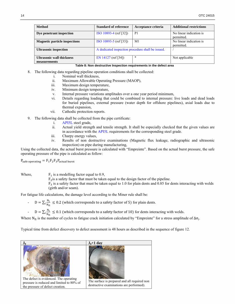
Typical time from defect discovery to defect assessment is 48 hours as described in the sequence of figure 12.
J0 J0+1 day
The defect is evidenced. The operating pressure is reduced and limited to 80% of the pressure of defect creation.
The surface is prepared and all required non destructive examinations are performed).

OTC 24015 15
J0+1 day J0+2 days J0+3 days (optional)
The data are received and used in “Empreinte” to prepare the model in an automated mode. The model is ready (the geometry of the virtual impactor is optimised). Calculations are run over the night.
Burst pressure is determined. In that case, it was calculated to 160 bars. The safe working pressure of the pipe without repair is determined: F1 = 0.9, F2 = 0.8 and F3 = 0.85. The safe operating pressure is 98 bars.
If deemed necessary a composite repair is installed. The installation pressure shall be below 80% of the minimum operating pressure.
Figure 12: Typical sequence for pipeline defect assessment using “Empreinte”
It must be noted that “Empreinte” has also already been used to assess defects on shallow water offshore pipeline (see. example of figure 13). The defect was evidenced by in line MFL inspection on an OD 10.75” pipe (API5L X52 - WT 8.6 mm).
Results of diving inspection and corresponding virtual tool “Empreinte calculations” Inspection allowed determining the dent profile (depths) and the pipe wall thicknesses in the dent area.
When performing the inspection, divers did evidence a freespan that was considered in the calculations (boundary conditions were adjusted).
The geometry of the virtual tool built from inspection results is shown below:
Using the virtual tool, the damage process is modeled.
Then, the pipe burst pressure is determined by “Empreinte” using the Riks modified method. The calculated burst pressure is just above 300 bars.
Figure 13: Use of “Empreinte” for defect assessment on an offshore pipeline
Finally, everytime a defect assessment is performed with “Empreinte”, sensitivity analysis are strongly recommended. It is of great interest to know the influence of such parameters as the dent depth or the material stress-strain curve on the calculated burst pressure. It is also interesting to note that “Empreinte” can be used not only for defect assessment but also for drop objects or trawl gear impact risks assessments. An example of a drop object risk assessment study is shown in figure 13.
Model preparation Impact modelling Dented pipe after tool removal

16 OTC 24015
The model is prepared automatically. Some “reference tools” geometries can be created and available in “Empreine” if necessary.
Impact is modeled.
The resulting dent geometry and local pipe wall thining is determined.
Then, the burst pressure of the damaged pipe can be determined so that the criticiality of the impact can be evaluated.
Figure 14: Use of “Empreinte” to perform risk assessments 5. Conclusions
The objective to have a tool able to perform pipeline defect assessment using a “level 3” approach in a short time period (typically 48 hours) has been reached with the development of “Empreinte”.
“Empreinte” has been validated by series of full scale tests and calculations for: - plain dents assessments in static and dynamic loading conditions, - dents with defects (notch, gouge …) provided there is no local microstructural changes due to dynamic thermal-
mechanical loading (this would create a “layer” of material with different mechanical behaviour possibly brittle).
It must be kept in mind that to perform a reliable defect assessment with “Empreinte”, accurate data (defect characterization, material stress-strain curve, damage model, fatigue initiation criterion …) are necessary except for plain dents in static loading conditions where some hypothesis regarding the material stress-strain curve can be considered for example. Nevertheless, this need for accurate data is obviously not a great challenge for new projects for which testing requirements can be adjusted accordingly. 6. Next steps
Several tests including a test of a pipe exhibiting a complex corrosion defect and a test of a pipe with a dent submitted to combined loading conditions (bending and internal pressure) are scheduled to extend the validation database of “Empreinte”. In parallel, “Empreinte” software interface is developed to make its use easier and to perform as much automatic analysis as possible. Automatic modelling of pipe in pipe configurations is under development as well as automatic modelling of corroded pipeline starting from laser scanning of the corroded surface (see. figure 15).
Figure 15: Example of corroded surface captured by laser scanning (external corrosion)

OTC 24015 17
It has been explained in this paper that for complex defects, detailed material data are required for the identification of the damage models. To do so, standardized tests protocols have been developed. For each new project, these tests will now be required. In addition, this is very important to capitalize the generated material data. Therefore, a database will be associated to “Empreinte” in order to keep available all tests results. As previously explained, composite repair is an option where the safe operating pressure without repair is too low. Therefore, it is of interest to develop the capability to design composite repairs in “Empreinte”. This is also an objective for the the next release of “Empreinte”. Finally, for deep offshore applications, a tool is under development to allow characterization of the defect (visual examination, defect profile determination, wall thickness measurements, ultrasonic inspection …) using a ROV. As explained before, the reliability of the data are obviously a key point whenever defects assessments with reduced conservatisms are targeted. 8. Acknoledgements
The authors wish to acknowledge TOTAL SA (Jérôme Woirin and Anne Courbot) for supporting the development of “Empreinte” and TECNITAS for developing “Empreinte” those last five years. The Ecole Nationale Supérieure des Mines de Paris (C. Soret, J. Besson and Y. Madi) and Mecamix (K. Dang Van and Z. Moumni) are also acknolodged for their contributions in the last developments of “Empreinte”. 9. References
1. Cosham, M. Kirkwood, “Best practice in pipeline defect assessment”, Proceedings of IPC 2000: International Pipeline Conference October 2000; Calgary, Alberta, Canada.
2. “Assessment methods for dents in pipelines. A report to the pipeline defect assessment manual joint industry project.” NR99014/4238.1.74/R3. Cosham A. Penspen limited.
3. Kiefner,J.F., Fracture Initiation, Paper G, 4th Symposium on Linepipe Research, AGA, Dallas, Texas, 1969.
4. Kiefner,J.F., Maxey,W.A., Eiber,R.J., and Duffy,A.R.; The Failure Stress Levels of Flaws in Pressurised Cylinders, ASTM STP 536, American Society for Testing and Materials, Philadelphia, 1973, pp. 461-481.
5. BS 7910 “Guide to methods for assessing the acceptability of flaws in metallic structures”.
6. Fowler J.R, Alexander C.R, Kovach C.R, Connelly L.M “Cyclic Pressure Fatigue Life of Pipelines with Plain Dents, Dents with Gouges, and Dents with Welds”. Final Report to the Pipeline Research Committee of the American Gas Association, Report PR-201-927 and PR-201-9324, Stress Engineering Services, Inc., June 1994.
7. Fowler J.R, Alexander C.R., Kovach P.J., Conelly L.M. “Fatigue Life of Pipelines with Dents and Gouges Subjected to Cyclic Internal Pressure” -, PD-Vol. 69, Pipeline Engineering, ASME, 1995.
8. Hopkins,P., Corder,I. and Corbin,P. “The Resistance of Gas Transmission Pipelines to Mechanical Damage”- Paper VIII-3, International Conference on Pipeline Reliability, Calgary, Canada, June 1992.
9. Hopkins,P., “The Significance of Mechanical Damage in Gas Transmission Pipelines” Paper 25, Volume II, Proceedings of EPRG/NG-18 Eighth Biennial Joint Technical Meeting on Line Pipe Research, Paris, France, 14-17 May 1991.
10. Baker M.Jr. “TTO Number 10, Integrity management program. Dent study final report.” Department of transportation – Research and special programs administration – Office of pipeline safety.
11. Besson J., Berdin C., Bugat S., Desmorat R., Feyel F., Forest S., Lorentz E., Maire E., Pardoen T., Pineau A., Tanguy B. “Local approach to fracture” Ecole des Mines de Paris – Les presses.
12. Corder I., Chatain P. “EPRG Recommendations for the Assessment of the Resistance of Pipelines to External Damage”, Proceeding of the EPRG/PRC 10th Biennial Joint Technical Meeting On Line Pipe Research, Cambridge, UK, April 1995.

18 OTC 24015
13. Freitas J., Albertazzi A., Coimbra de Andrade D., “New Strain Assessment Methodology in Pipeline Dents of Complex Shapes” - IPC2012-90411.
14. Guerreiro J.N.C., Noronha Jr D.B., Martins R.R., Fonseca L.G., Lopes T.V., Costa M.F., Da Silva Castro E. “A Program For Strain Based Assessment Of Pipeline Dents With Complex Shape” IPC2012-90434.
15. Coppola T., Demofonti G., Mannucci G. “Numerical-Experimental Procedures To Identify The Ductile Fracture Strain Limits In Pipeline Steels” Proceedings of the Nineteenth (2009) International Offshore and Polar Engineering Conference - Osaka, Japan, June 21-26, 2009 - ISBN 978-1-880653-53-1 (Set); ISSN 1098-618
16. Coppola T., Demofonti G. “Advanced methods for the strain limit assessment in pipeline applications subjected to extreme loading” 2nd ISOPE Strain Based Design Symposium, SBD 2008, Paper N. ISOPE-2008-TPC-704 Vancouver, Canada, July 6-11, 2008.
17. Demofonti G., Di Biagio M., Iob F. “Developement of a reliable model for evaluating the ductile fracture propagation resistance for high grade steel pipelines” Centro Sviluppo Materiali S.P.A., Rome, Italy, C.M. Spinelli - ENI gas&power, Milano, Italy - P. Roovers Fluxys, Brussel, Belgium.
18. “Pipeline Rupture in Abaqus/Standard with Ductile Failure Initiation” Abaqus Technical Brief. Simulia. Dassault Systems.
19. Mc Donald K.A., Cosham A. “Best practice for the assessment of defects in pipelines – Gouges and dents” Engineering failure analysis 12(2005) 720-745.
20. Champavere R., Zarea M., Batisse R. “Fatigue behaviour of steel pipes containing dent and gouge combination”, Pipeline Techonology vol II R. Denys (Editor).
21. Mokhdani C. “Amorçage et propagation de fissures de fatigue dans un acier pour tubes de transport de gaz. Identification des lois d’endommagement et application aux structures tube sous pression interne” - Thèse de doctorat d’état de l’Ecole Nationale Supérieure des Mines de Paris - 1995.
22. PRCI project MD-4-9.
23. DNV OS F101 “Submarine pipelines”.
24. DNV RP F101 “Corroded pipelines”.
25. DNV RP F111 “Interference between trawl gear and pipelines”.
26. DNV RP F107 “Risk assessment of pipeline protection”.
27. ASME B31.4 “Pipelines transportation systems for liquid hydrocarbons and other liquids”.
28. ASME B31.8 “Gas transmission adnd distribution piping systems”.
29. CSA Z662 “Oil and gas pipeline systems”.
30. API 5L “Specification for linepipe”
31. API 1104 “Standard for welding pipelines and related facilities”.
32. ISO 10893-4 “Non-destructive testing of steel tubes - Part 4: Liquid penetrant inspection of seamless and welded steel tubes for the detection of surface imperfections”
33. ISO 10893-5 “Non-destructive testing of steel tubes - Part 5: Magnetic particle inspection of seamless and welded ferromagnetic steel tubes for the detection of surface imperfections”.
34. EN 14127 “Non-destructive testing. Ultrasonic thickness measurement”.