OSS RULES TRAINING CONTROLLED FILL MOUNDS – JAN 2006 Chapter 420-3-1-.67.
57
OSS RULES TRAINING CONTROLLED FILL MOUNDS – JAN 2006 Chapter 420-3-1-.67
-
Upload
bartholomew-anthony -
Category
Documents
-
view
216 -
download
0
Transcript of OSS RULES TRAINING CONTROLLED FILL MOUNDS – JAN 2006 Chapter 420-3-1-.67.

OSS RULES TRAININGCONTROLLED FILLMOUNDS – JAN 2006
Chapter 420-3-1-.67
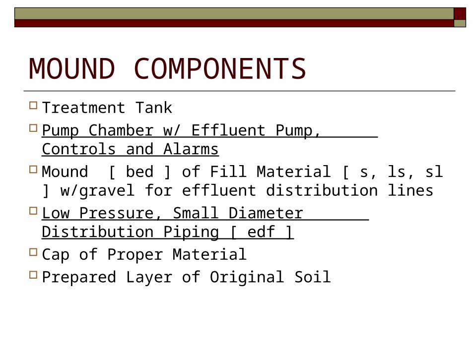
MOUND COMPONENTS Treatment Tank Pump Chamber w/ Effluent Pump, Controls and
Alarms Mound [ bed ] of Fill Material [ s, ls, sl ] w/gravel
for effluent distribution lines Low Pressure, Small Diameter Distribution
Piping [ edf ] Cap of Proper Material Prepared Layer of Original Soil
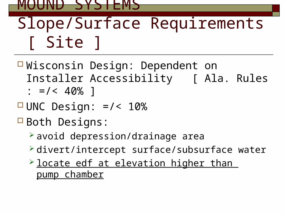
MOUND SYSTEMSSlope/Surface Requirements [ Site ] Wisconsin Design: Dependent on Installer
Accessibility [ Ala. Rules : =/< 40% ] UNC Design: =/< 10% Both Designs:
avoid depression/drainage area divert/intercept surface/subsurface water locate edf at elevation higher than
pump chamber
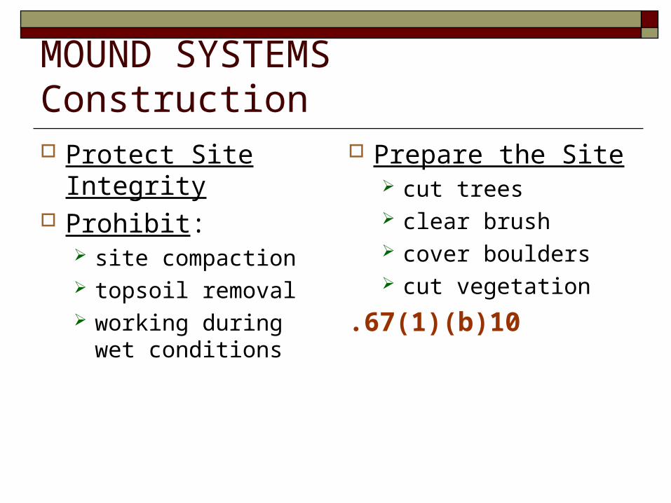
MOUND SYSTEMSConstruction Protect Site Integrity Prohibit:
site compaction topsoil removal working during wet
conditions
Prepare the Site cut trees clear brush cover boulders cut vegetation
.67(1)(b)10

MOUND SYSTEMSConstruction Scarify [break up] Original Soil
6 – 8 inch depth moisture range satisfactory
• soil crumbles rather than beads use proper equipment
• chisel teeth attached to backhoe• chisel plow• bucket with short teeth
** rototillers are not recommended .67(1)(b)10
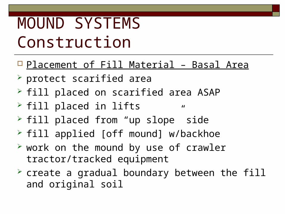
MOUND SYSTEMSConstruction Placement of Fill Material – Basal Area protect scarified area fill placed on scarified area ASAP fill placed in lifts fill placed from “up slope” side fill applied [off mound] w/backhoe work on the mound by use of crawler tractor/tracked
equipment create a gradual boundary between the fill and original soil
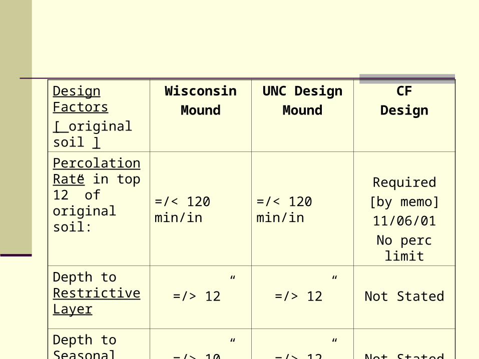
Design Factors
[ original soil ]
Wisconsin
Mound
UNC Design
Mound
CF
Design
Percolation Rate in top 12” of original soil: =/< 120 min/in =/< 120 min/in
Required
[by memo]
11/06/01
No perc limit
Depth to Restrictive Layer
=/> 12” =/> 12” Not Stated
Depth to Seasonal Water Table
=/> 10” =/> 12” Not Stated


CONTROLLED FILL REQUIREMENTS FOR NEW RULES Design Calculations Established/Defined
Terms defined Perc table expanded for sizing EDFs with 4”pipe/gravel Loading rates and correction factors established use with LPP
designs [soil loading rates, linear loading rates for site conditions, slope correction factors]
Minimum standards for side/end slopes, separation distances from sidewalls to side/end slopes, etc.
Minimum standards for high certain high shrink/swell soils Fill Placement / Bed Construction Standards Allowable Reductions Established Five Basic Design Modes for Approval by LHD
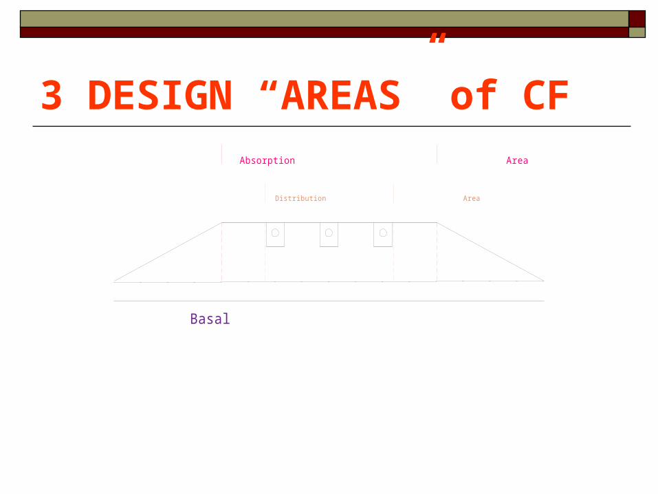
Distribution Area
Absorption Area
Basal Area
3 DESIGN “AREAS” of CF

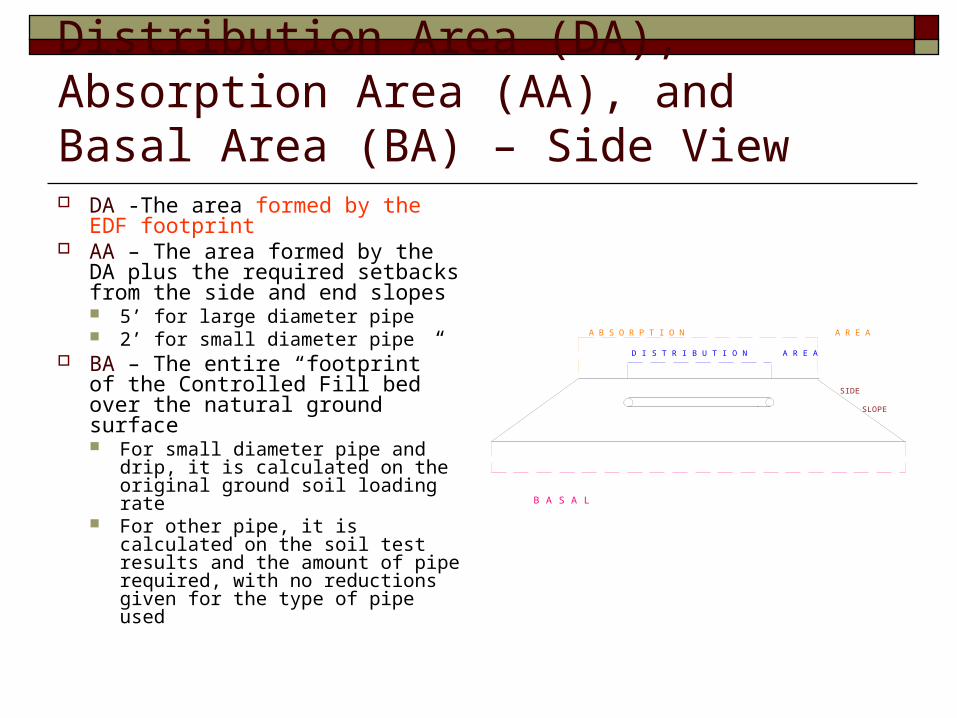
Distribution Area (DA), Absorption Area (AA), and Basal Area (BA) – End View DA -The area formed by the EDF
footprint AA – The area formed by the DA
plus the required setbacks from the side and end slopes 5’ for large diameter pipe 2’ for small diameter pipe
BA – The entire “footprint” of the Controlled Fill bed over the natural ground surface For small diameter pipe and drip, it is
calculated on the original ground soil loading rate
For other pipe, it is calculated on the soil test results and the amount of pipe required, with no reductions given for the type of pipe used
A B S O R P T I O N A R E A
D I S T R I B U T I O N A R E A
B A S A L A R E A
SIDE
SLOPE
Distribution Area (DA), Absorption Area (AA), and Basal Area (BA) – Side View DA -The area formed by the EDF
footprint AA – The area formed by the DA
plus the required setbacks from the side and end slopes 5’ for large diameter pipe 2’ for small diameter pipe
BA – The entire “footprint” of the Controlled Fill bed over the natural ground surface For small diameter pipe and drip, it is
calculated on the original ground soil loading rate
For other pipe, it is calculated on the soil test results and the amount of pipe required, with no reductions given for the type of pipe used
A B S O R P T I O N A R E A
D I S T R I B U T I O N A R E A
B A S A L A R E A
SIDE
SLOPE
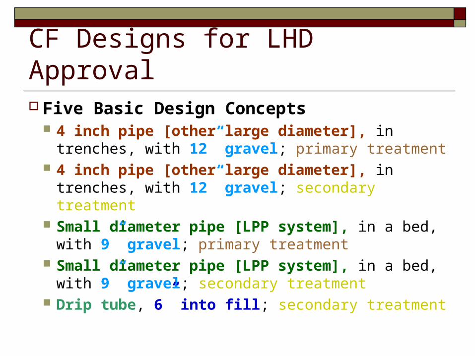
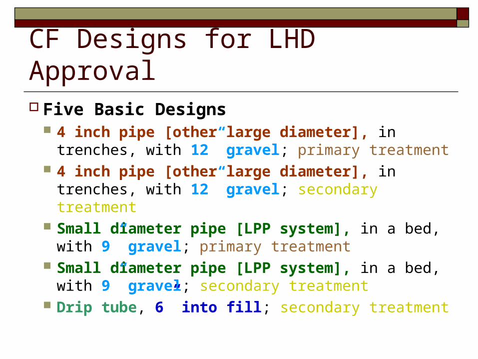
CF Designs for LHD Approval Five Basic Design Concepts
4 inch pipe [other large diameter], in trenches, with 12” gravel; primary treatment
4 inch pipe [other large diameter], in trenches, with 12” gravel; secondary treatment
Small diameter pipe [LPP system], in a bed, with 9” gravel; primary treatment
Small diameter pipe [LPP system], in a bed, with 9” gravel; secondary treatment
Drip tube, 6” into fill; secondary treatment
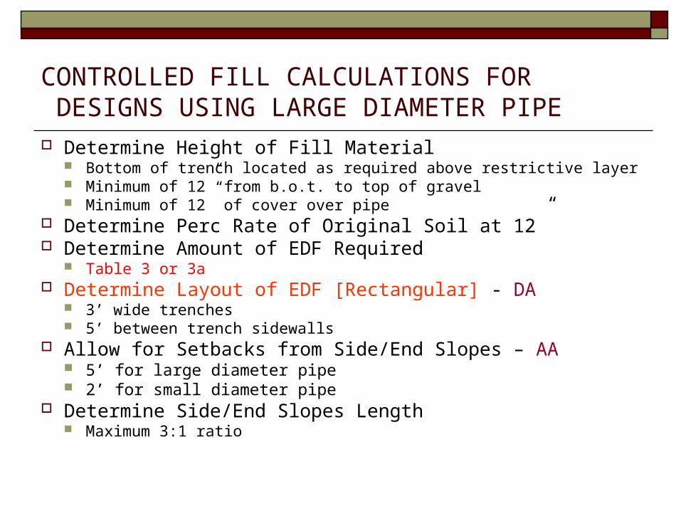
CONTROLLED FILL CALCULATIONS FOR DESIGNS USING LARGE DIAMETER PIPE Determine Height of Fill Material
Bottom of trench located as required above restrictive layer Minimum of 12” from b.o.t. to top of gravel Minimum of 12” of cover over pipe
Determine Perc Rate of Original Soil at 12” Determine Amount of EDF Required
Table 3 or 3a Determine Layout of EDF [Rectangular] - DA
3’ wide trenches 5’ between trench sidewalls
Allow for Setbacks from Side/End Slopes – AA 5’ for large diameter pipe 2’ for small diameter pipe
Determine Side/End Slopes Length Maximum 3:1 ratio

DA for CF Using Large Diameter Pipe
A B S O R P T I O N A R E A
D I S T R I B U T I O N A R E A
B A S A L A R E A
SIDE
SLOPE
A B S O R P T I O N A R E A
D I S T R I B U T I O N A R E A
B A S A L A R E A
SIDE
SLOPE

Perc Tables Review of Current Tables
Rules: 1 – 60 min/inch Mound Manuals: up to 120 min/inch Alternating Field Formula: up to 120 min/inch Drip Charts: >120 min/inch
New Rules Table 3: up to 120 min/inch
Conventional OSS Table 3a: 121 – 240 min/inch
High Shrink-Swell Soils and Poorly Structured Soils Minimum Design Rate of 180 min/inch in Vertisols & vertic soils
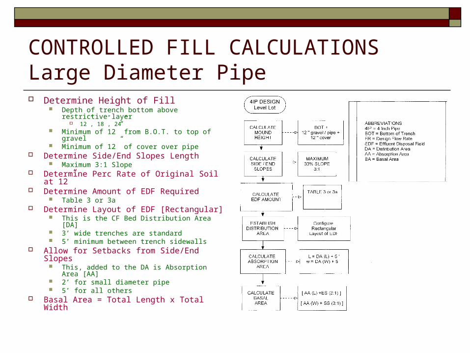
CONTROLLED FILL CALCULATIONSLarge Diameter Pipe Determine Height of Fill
Depth of trench bottom above restrictive layer 12”, 18”, 24”
Minimum of 12” from B.O.T. to top of gravel Minimum of 12” of cover over pipe
Determine Side/End Slopes Length Maximum 3:1 Slope
Determine Perc Rate of Original Soil at 12” Determine Amount of EDF Required
Table 3 or 3a Determine Layout of EDF [Rectangular]
This is the CF Bed Distribution Area [DA] 3’ wide trenches are standard 5’ minimum between trench sidewalls
Allow for Setbacks from Side/End Slopes This, added to the DA is Absorption Area [AA] 2’ for small diameter pipe 5’ for all others
Basal Area = Total Length x Total Width

CONTROLLED FILL CALCULATIONSLarge Diameter Pipe Determine Height of Fill
Depth of trench bottom above restrictive layer Minimum of 12” from B.O.T. to top of gravel Minimum of 12” of cover over pipe
Determine Perc Rate of Original Soil at 12” Determine Amount of EDF Required
Table 3 or 3a Determine Layout of EDF [Rectangular]
This is the CF Bed Distribution Area [DA] 3’ wide trenches are standard 5’ minimum between trench sidewalls
Allow for Setbacks from Side/End Slopes This, added to the DA is Absorption Area [AA]
Determine Side/End Slopes Length Maximum 3:1 Slope
Basal Area = Total Length x Total Width

Layout Configurations Using 4 inch Pipe with Gravel 3 bdrm dwelling; flat lot; ASHES @ 12”; perc of 90 @ 12”450 LF of EDF Boxed Ends as part of EDF
DA = 2807 ft2; AA = 4059 ft2; BA = 6312 ft2
Header as part of EDF DA = 2978.5ft2; AA = 4279.5ft2; BA = 6606 ft2
Center manifold as part of EDF DA = 3010 ft2; AA = 4320 ft2; BA = 6660 ft2
Center manifold; not part of EDF DA = 3150 ft2; AA = 4500 ft2; BA = 6900 ft2
Header; not part of EDF DA =3202.5 ft2; AA = 4567.5 ft2; BA = 6990 ft2
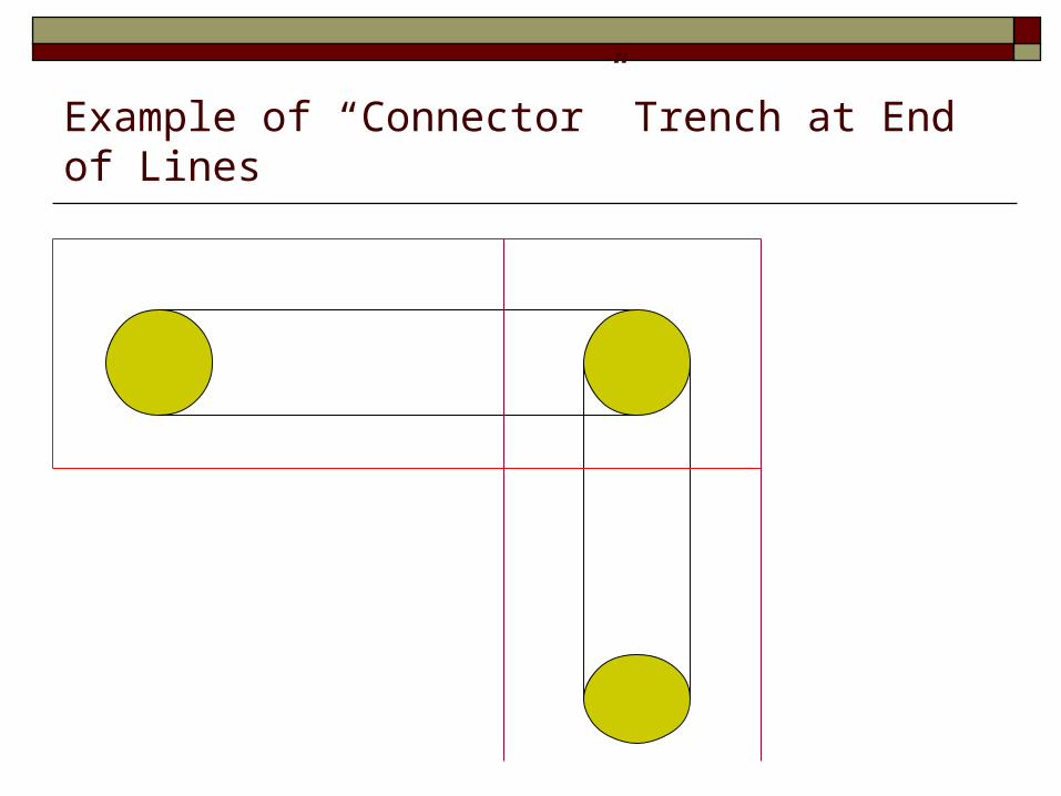
Example of “Connector” Trench at End of Lines


LARGE DIAMETER PIPE IN CONTROLLED FILL Points to Remember
BA reductions not given for type of pipe used Large diameter pipe to be used in trenches Designs utilizing large diameter pipe in gravel bed
must be reviewed at State level Reductions in required separation from limiting
zone may by BE GIVEN FOR ALL PIPES if effluent is pre-treated to secondary levels

CF Designs on Other Restrictive Sites Minimum Above Ground Height of Trench Bottom
6”; trench bottoms not located at <6” [.67(1)(d)] Pre-Treatment (Secondary Standards) Required:
Sites with <6 inches to ASHES [.67(1)(e)] (Average Seasonal High Extended Saturation)
Sites with <6 inches to ASHES [.67(1)(e)] (Average Seasonal High Extended Saturation)
Sites with <12 inches to Rock [.67(1)(f)]

DESIGN EXAMPLE #13 bdrm. dwelling; flat lot; ASHES @12”; perc @ 12” = 90 min / inch
CALCULATE HEIGHT OF FILL B.O.T [ Table 15 ] B.O.T. + 12” [pipe/gravel] + 12”cover
DETERMINE SIDE/END SLOPES 33.3% maximum slope [3:1]
CALCULATE EDF AMOUNT Table 3
DETERMINE EDF LAYOUT Rectangular
DETERMINE DA DETERMINE AA
5’ setback on all sides DETERMINE BASAL AREA
L = AA(L) + ES W = AA(W) + SS
HEIGHT = 30” above NGS [BOT] 6” + 12” + 12” = 30” above ngs
90” / 12” = 7.5’ per side / end 3 x 30” = 90“
150’ / 3’ per bedroom 450 LF of 3’ trench
5 x 77. 2’ lines + ends [ 2 x 32’] 386’ + 64’ = 450 LF
DA = 80.2’ x 35’ = 2807 ft2 Includes 1.5’ on each end
AA = 90.2’ x 45’ = 4059 ft2 [80.2’+10’] x [35’ + 10’]
BA = 105.2’ x 60’ = 6312 ft2 [90.2’+15”] x [35’ + 15’]

Examples: Five CF Designs with Minimum Standards for LHD Approval (Design Examples based on: 3 bdrm. dwelling; level lot; 450 gpd; restrictive layer at 12”; perc at 12” equal to 90 min/inch)
4 inch pipe, in trenches, with 12” gravel; primary treatment [all
figures are minimum] EDF Pipe: 450 lin.ft. in 3’ trenches
5 lines: each 77.2’ long connection trenches on each end; each 32’ long
DA Size: 2,807 ft2 (Appr. 80.2’ x 35’) AA Size: 4,059 ft2 (Appr. 90.2’ x 45’) – 5’ setbacks BA Size: 6,312 ft2 (Appr. 105.2’ x 60’)
B.O.T.= 6”above natural ground, + 12” w/pipe and gravel; + 12” cover = 30” above NGS
3:1 slope @ 30” (2.5’) height = Appr. 7.5’ length on each side/end
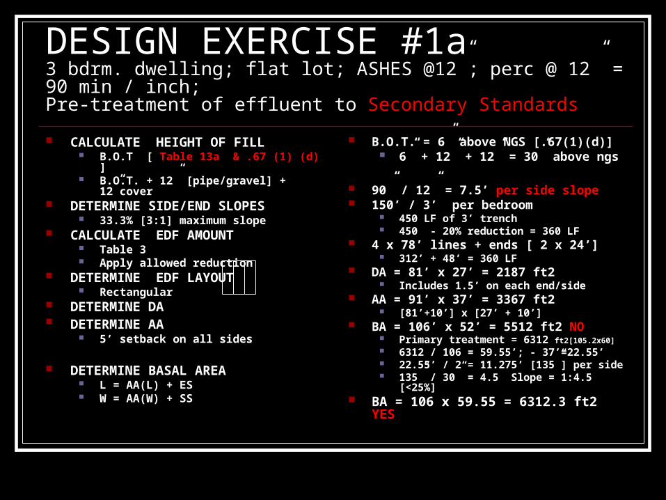
DESIGN EXERCISE #1a3 bdrm. dwelling; flat lot; ASHES @12”; perc @ 12” = 90 min / inch;Pre-treatment of effluent to Secondary Standards
CALCULATE HEIGHT OF FILL B.O.T [ Table 13a & .67 (1) (d) ] B.O.T. + 12” [pipe/gravel] + 12”cover
DETERMINE SIDE/END SLOPES 33.3% [3:1] maximum slope
CALCULATE EDF AMOUNT Table 3 Apply allowed reduction
DETERMINE EDF LAYOUT Rectangular
DETERMINE DA DETERMINE AA
5’ setback on all sides
DETERMINE BASAL AREA L = AA(L) + ES W = AA(W) + SS
B.O.T. = 6” above NGS [.67(1)(d)] 6” + 12” + 12” = 30” above ngs
90” / 12” = 7.5’ per side slope 150’ / 3’ per bedroom
450 LF of 3’ trench 450 - 20% reduction = 360 LF
4 x 78’ lines + ends [ 2 x 24’] 312’ + 48’ = 360 LF
DA = 81’ x 27’ = 2187 ft2 Includes 1.5’ on each end/side
AA = 91’ x 37’ = 3367 ft2 [81’+10’] x [27’ + 10’]
BA = 106’ x 52’ = 5512 ft2 NO Primary treatment = 6312 ft2[105.2x60] 6312 / 106 = 59.55’; - 37’=22.55’ 22.55’ / 2 = 11.275’ [135”] per side 135” / 30” = 4.5 Slope = 1:4.5 [<25%]
BA = 106 x 59.55 = 6312.3 ft2 YES

Examples: Five CF Designs with Minimum Standards for LHD Approval (Design Examples based on: 3 bdrm. dwelling; level lot; 450 gpd; restrictive layer at 12”; perc at 12” equal to 90 min/inch) 4 inch pipe, in trenches, with 12” gravel; secondary treatment
[all figures are minimum] – Appr. 20% reduction in EDF EDF Pipe: 360 lin.ft. in 3’ trenches [minimum of 360’ req’d]
4 lines: each 78’ long connection lines on each end; each 24’ long
DA Size: 2,187 ft2 (Appr. 81’x 27’) AA Size: 3,367 ft2 (Appr. 91’x 37’) – 5’ setbacks BA Size: 6,312 ft2 (Appr. 106’x 59.55’)
B.O.T.= 6”above natural ground, + 12” w/pipe and gravel; + 12” cover = 30” above NGS
3:1 slope @ 30” (2.50’) height = Appr. 7.5’ length on each end 4.5:1 slope @ 30’ height = Appr. 11.275’ length on each side
CF Designs for LHD Approval Five Basic Designs
4 inch pipe [other large diameter], in trenches, with 12” gravel; primary treatment
4 inch pipe [other large diameter], in trenches, with 12” gravel; secondary treatment
Small diameter pipe [LPP system], in a bed, with 9” gravel; primary treatment
Small diameter pipe [LPP system], in a bed, with 9” gravel; secondary treatment
Drip tube, 6” into fill; secondary treatment
Design Standards for CF Utilizing Low Pressure Pipe [LPP] Linear Loading Rate [LLR]
An estimation of the amount of effluent (gpd) that will be dispersed along each linear foot of LPP. Dependent on: direction of flow away from CF bed
underlying soils surface slope
amount of flow away from CF bed
Slope Correction Factor Applied when CF installed on non-level sites
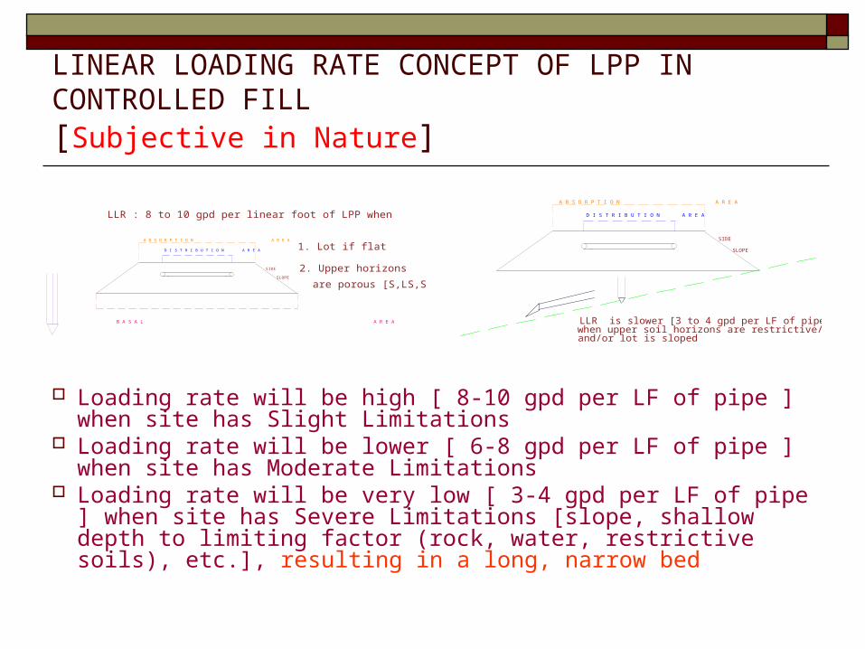
LINEAR LOADING RATE CONCEPT OF LPP IN CONTROLLED FILL[Subjective in Nature]
Loading rate will be high [ 8-10 gpd per LF of pipe ] when site has Slight Limitations
Loading rate will be lower [ 6-8 gpd per LF of pipe ] when site has Moderate Limitations
Loading rate will be very low [ 3-4 gpd per LF of pipe ] when site has Severe Limitations [slope, shallow depth to limiting factor (rock, water, restrictive soils), etc.], resulting in a long, narrow bed
A B S O R P T I O N A R E A
D I S T R I B U T I O N A R E A
B A S A L A R E A
SIDE
SLOPE
LLR : 8 to 10 gpd per linear foot of LPP when
1. Lot if flat
2. Upper horizonsare porous [S,LS,SL]
A B S O R P T I O N A R E A
D I S T R I B U T I O N A R E A
SIDE
SLOPE
LLR is slower [3 to 4 gpd per LF of pipe]when upper soil horizons are restrictive/limitingand/or lot is sloped
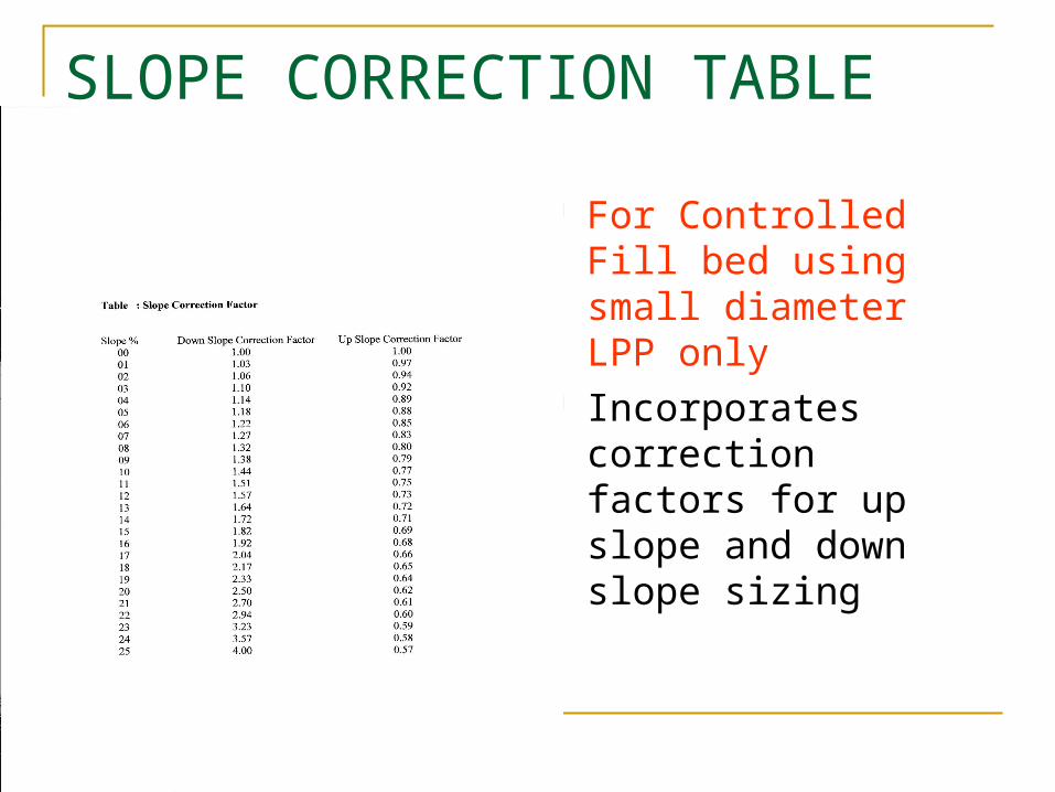
SLOPE CORRECTION TABLE
For Controlled Fill bed using small diameter LPP only
Incorporates correction factors for up slope and down slope sizing
Design Standards for CF Utilizing Low Pressure Pipe [LPP] Fill Material Loading Rate
Tables 11 and 13 Loading Rate by Fill Type
Basal Area Loading Rate Table 12 Loading Rate of Uppers Horizons of Original
Ground under the CF Bed
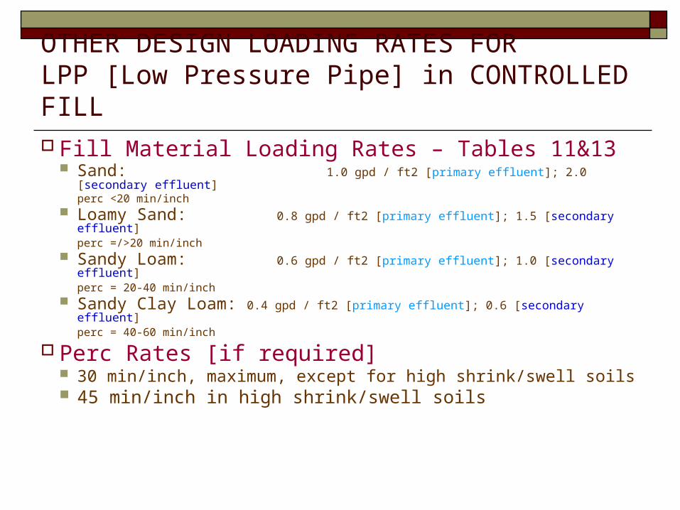
OTHER DESIGN LOADING RATES FORLPP [Low Pressure Pipe] in CONTROLLED FILL
Fill Material Loading Rates – Tables 11&13 Sand: 1.0 gpd / ft2 [primary effluent]; 2.0 [secondary effluent]
perc <20 min/inch Loamy Sand: 0.8 gpd / ft2 [primary effluent]; 1.5 [secondary effluent]
perc =/>20 min/inch Sandy Loam: 0.6 gpd / ft2 [primary effluent]; 1.0 [secondary effluent]
perc = 20-40 min/inch Sandy Clay Loam: 0.4 gpd / ft2 [primary effluent]; 0.6 [secondary effluent]
perc = 40-60 min/inch
Perc Rates [if required] 30 min/inch, maximum, except for high shrink/swell soils 45 min/inch in high shrink/swell soils
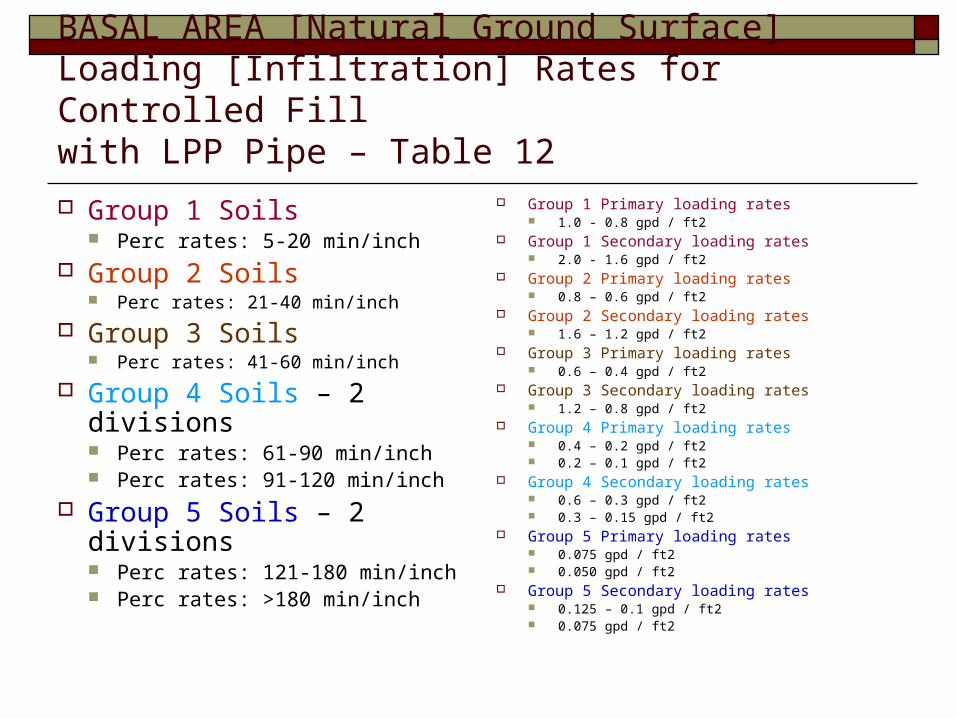
BASAL AREA [Natural Ground Surface]Loading [Infiltration] Rates for Controlled Fill with LPP Pipe – Table 12
Group 1 Soils Perc rates: 5-20 min/inch
Group 2 Soils Perc rates: 21-40 min/inch
Group 3 Soils Perc rates: 41-60 min/inch
Group 4 Soils – 2 divisions Perc rates: 61-90 min/inch Perc rates: 91-120 min/inch
Group 5 Soils – 2 divisions Perc rates: 121-180 min/inch Perc rates: >180 min/inch
Group 1 Primary loading rates 1.0 - 0.8 gpd / ft2
Group 1 Secondary loading rates 2.0 - 1.6 gpd / ft2
Group 2 Primary loading rates 0.8 – 0.6 gpd / ft2
Group 2 Secondary loading rates 1.6 – 1.2 gpd / ft2
Group 3 Primary loading rates 0.6 – 0.4 gpd / ft2
Group 3 Secondary loading rates 1.2 – 0.8 gpd / ft2
Group 4 Primary loading rates 0.4 – 0.2 gpd / ft2 0.2 – 0.1 gpd / ft2
Group 4 Secondary loading rates 0.6 – 0.3 gpd / ft2 0.3 – 0.15 gpd / ft2
Group 5 Primary loading rates 0.075 gpd / ft2 0.050 gpd / ft2
Group 5 Secondary loading rates 0.125 – 0.1 gpd / ft2 0.075 gpd / ft2
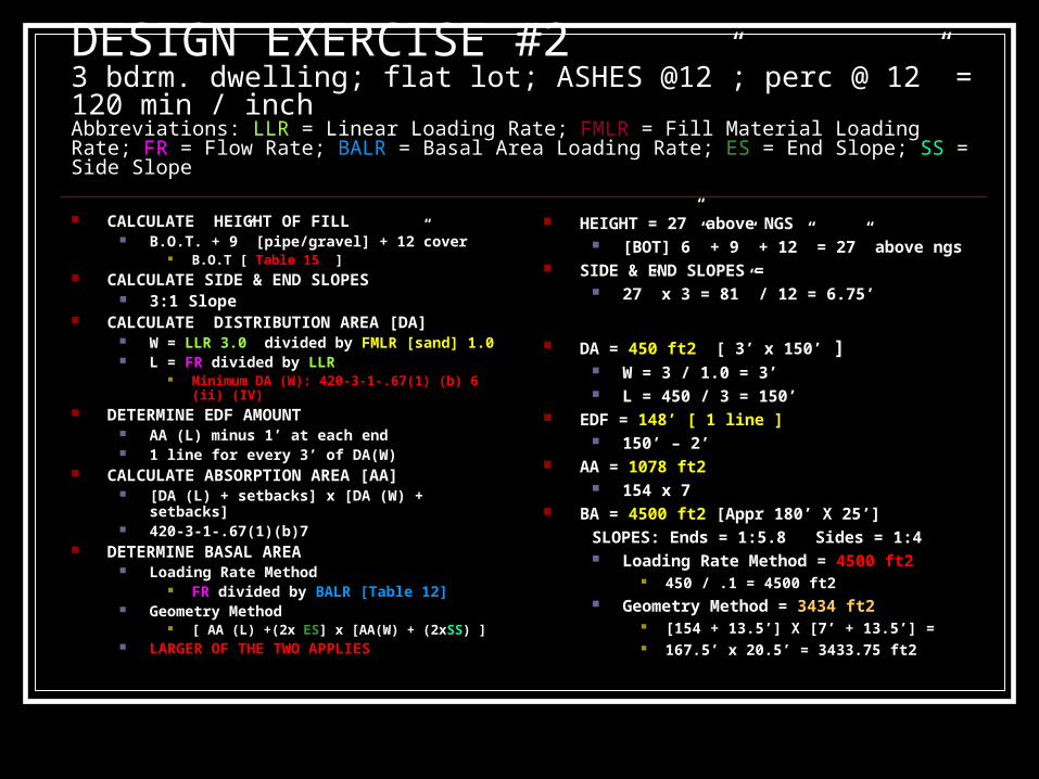
DESIGN EXERCISE #23 bdrm. dwelling; flat lot; ASHES @12”; perc @ 12” = 120 min / inchAbbreviations: LLR = Linear Loading Rate; FMLR = Fill Material Loading Rate; FR = Flow Rate; BALR = Basal Area Loading Rate; ES = End Slope; SS = Side Slope
CALCULATE HEIGHT OF FILL B.O.T. + 9” [pipe/gravel] + 12”cover
B.O.T [ Table 15 ] CALCULATE SIDE & END SLOPES
3:1 Slope CALCULATE DISTRIBUTION AREA [DA]
W = LLR 3.0 divided by FMLR [sand] 1.0 L = FR divided by LLR
Minimum DA (W): 420-3-1-.67(1) (b) 6 (ii) (IV) DETERMINE EDF AMOUNT
AA (L) minus 1’ at each end 1 line for every 3’ of DA(W)
CALCULATE ABSORPTION AREA [AA] [DA (L) + setbacks] x [DA (W) + setbacks] 420-3-1-.67(1)(b)7
DETERMINE BASAL AREA Loading Rate Method
FR divided by BALR [Table 12] Geometry Method
[ AA (L) +(2x ES] x [AA(W) + (2xSS) ] LARGER OF THE TWO APPLIES
HEIGHT = 27” above NGS [BOT] 6” + 9” + 12” = 27” above ngs
SIDE & END SLOPES = 27” x 3 = 81” / 12 = 6.75’
DA = 450 ft2 [ 3’ x 150’ ] W = 3 / 1.0 = 3’ L = 450 / 3 = 150’
EDF = 148’ [ 1 line ] 150’ – 2’
AA = 1078 ft2 154 x 7
BA = 4500 ft2 [Appr 180’ X 25’]
SLOPES: Ends = 1:5.8 Sides = 1:4 Loading Rate Method = 4500 ft2
450 / .1 = 4500 ft2 Geometry Method = 3434 ft2
[154 + 13.5’] X [7’ + 13.5’] = 167.5’ x 20.5’ = 3433.75 ft2

DESIGN EXERCISE #2a3 bdrm. dwelling; flat lot; ASHES @ 12”; perc @ 12” = 120 min / inch;Pre-treatment of effluent to Secondary StandardsAbbreviations: LLR = Linear Loading Rate; FMLR = Fill Material Loading Rate; FR = Flow Rate; BALR = Basal Area Loading Rate; ES = End Slope; SS = Side Slope
CALCULATE HEIGHT OF FILL B.O.T. + 9” [pipe/gravel] + 12”cover
B.O.T [ Tables 15,13 & .67(1) (d) ] CALCULATE SIDE & END SLOPES
3:1 Slope CALCULATE DISTRIBUTION AREA [DA]
W = LLR 3.0 divided by FMLR [sand] 2.0 Table 13 L = FR divided by LLR
Minimum DA (W): 420-3-1-.67(1) (b) 6 (ii) (IV) DETERMINE EDF AMOUNT
AA (L) minus 1’ at each end 1 line for every 3’ of DA(W)
CALCULATE ABSORPTION AREA [AA] [DA (L) + setbacks] x [DA (W) + setbacks] 420-3-1-.67(1)(b)7
DETERMINE BASAL AREA Loading Rate Method
FR divided by BALR [Table 12] Geometry Method
[ AA (L) +(2x ES] x [AA(W) + (2xSS) ] LARGER OF THE TWO APPLIES
HEIGHT = 27” above NGS [BOT] 6” + 9” + 12” = 27” above ngs
SIDE & END SLOPES = 27” x 3 = 81” / 12 = 6.75’
DA = 450 ft2 [ 3’ x 150’ ] W = 3 / 2.0 = 1.5’ [3’minimum] L = 450 / 3 = 150’
EDF = 148’ [ 1 line ] 150’ – 2’
AA = 1078 ft2 154 x 7
BA = 3434 ft2 [Appr 167.5’ X 20.5’]SLOPES: Ends = 3:1 Sides = 3:1 Loading Rate Method = 3000 ft2
450 / .15 = 3000 ft2 Geometry Method = 3434 ft2
[154 + 13.5’] X [7’ + 13.5’] = 167.5’ x 20.5’ = 3433.75 ft2
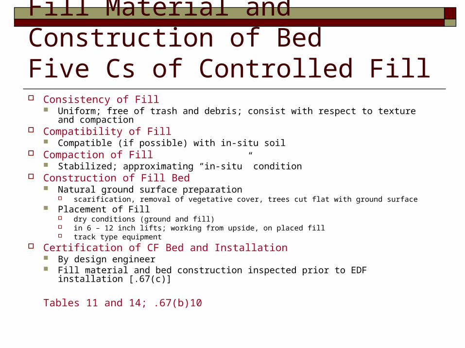
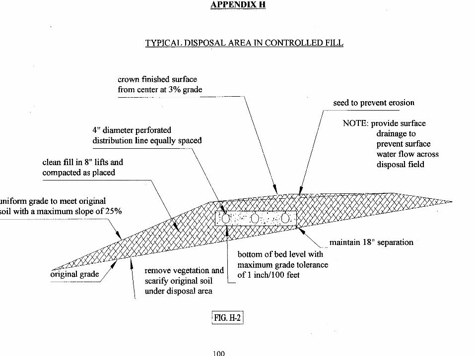
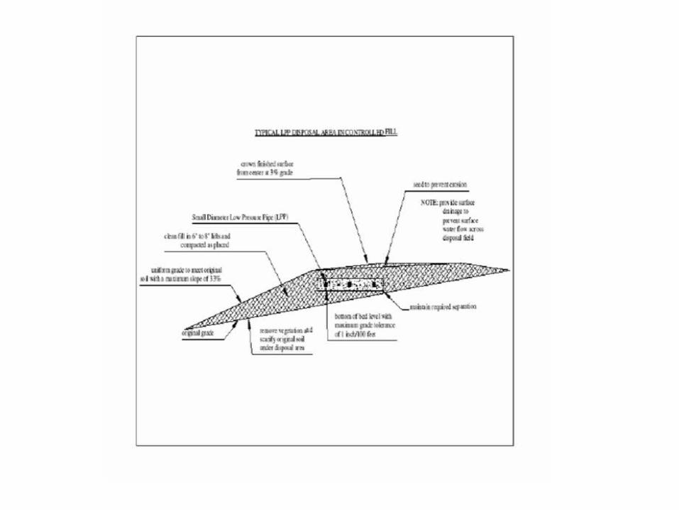
Fill Material and Construction of BedFive Cs of Controlled Fill Consistency of Fill
Uniform; free of trash and debris; consist with respect to texture and compaction Compatibility of Fill
Compatible (if possible) with in-situ soil Compaction of Fill
Stabilized; approximating “in-situ” condition Construction of Fill Bed
Natural ground surface preparation scarification, removal of vegetative cover, trees cut flat with ground surface
Placement of Fill dry conditions (ground and fill) in 6 – 12 inch lifts; working from upside, on placed fill track type equipment
Certification of CF Bed and Installation By design engineer Fill material and bed construction inspected prior to EDF installation [.67(c)]
Tables 11 and 14; .67(b)10
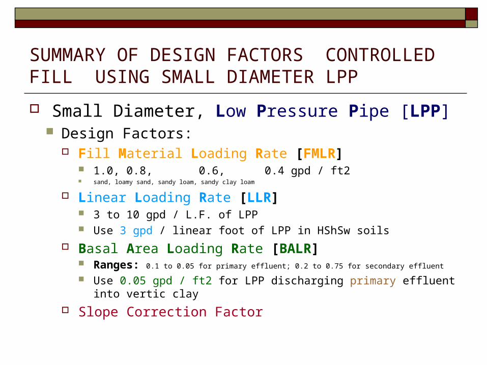
SUMMARY OF DESIGN FACTORS CONTROLLED FILL USING SMALL DIAMETER LPP
Small Diameter, Low Pressure Pipe [LPP] Design Factors:
Fill Material Loading Rate [FMLR] 1.0, 0.8, 0.6, 0.4 gpd / ft2 sand, loamy sand, sandy loam, sandy clay loam
Linear Loading Rate [LLR] 3 to 10 gpd / L.F. of LPP Use 3 gpd / linear foot of LPP in HShSw soils
Basal Area Loading Rate [BALR] Ranges: 0.1 to 0.05 for primary effluent; 0.2 to 0.75 for secondary effluent
Use 0.05 gpd / ft2 for LPP discharging primary effluent into vertic clay
Slope Correction Factor

DESIGN EXERCISE #3 - LPP3 bdrm. dwelling; 10% sloped lot; ASHES @12”; perc @ 12” = 50 min / inchAbbreviations: LLR = Linear Loading Rate; FMLR = Fill Material Loading Rate; FR = Flow Rate; BALR = Basal Area Loading Rate; ES = End Slope; SS = Side Slope; NGS = Natural Ground Surface
CALCULATE DISTRIBUTION AREA [DA]
W = LLR 6 Divided by FMLR 1.0 L = FR divided by LLR
DETERMINE B.O.T. HEIGHTS Upslope [Us BOT] height =
Required Distance above ASHES BOT [ Table 15 ]
Downslope [Ds BOT] height =
[Us BOT] + [slope% x DA(W)]
CALCULATE FILL HEIGHTS Upslope= UsBOT + gravel/pipe +
cover Downslope= DsBOT + gravel/pipe +
cover
DA = 450 ft2 [ 6’ x 75’ ] W = 6 / 1.0 = 6’ L = 450 / 6 = 75’
UPSLOPE [Us BOT] HT. = 12” over NGS 24” above ASHES = 12” over NGS 12” below NGS + 24” = 12” over NGS
DOWNSLOPE [Ds BOT] HT. = 19” over NGS 12” + [.10 X 72”] = 12” + 7” = 19” over
NGS
FILL HEIGHTS = 33” & 40” U.s. Ht. = 12” + 9” + 12” = 33” D.s. Ht. = 19” + 9” + 12” = 40”
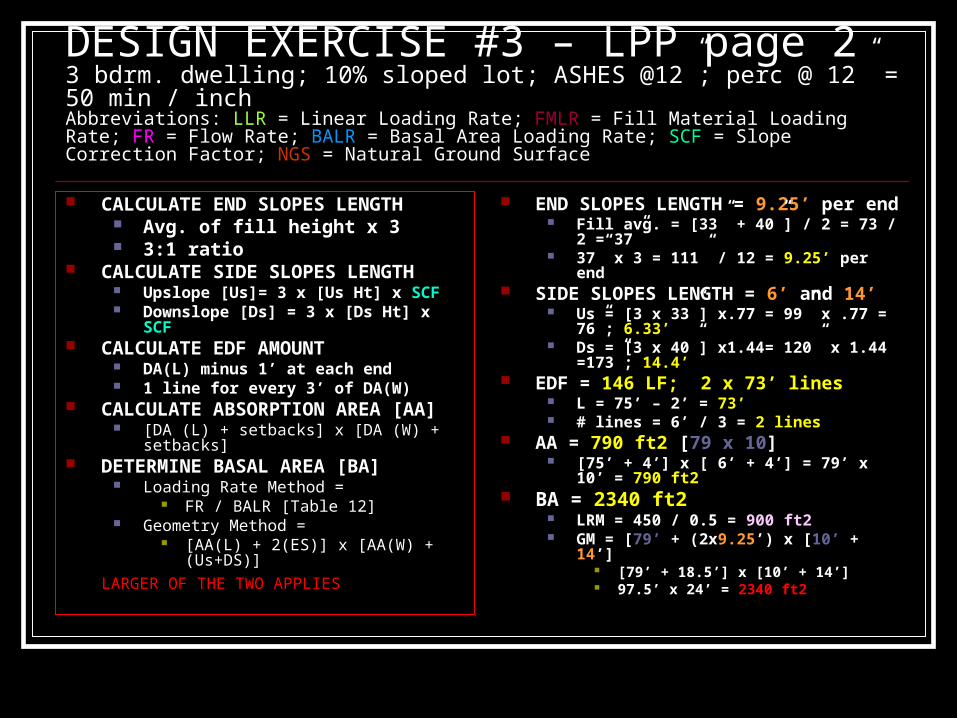
DESIGN EXERCISE #3 – LPP page 23 bdrm. dwelling; 10% sloped lot; ASHES @12”; perc @ 12” = 50 min / inchAbbreviations: LLR = Linear Loading Rate; FMLR = Fill Material Loading Rate; FR = Flow Rate; BALR = Basal Area Loading Rate; SCF = Slope Correction Factor; NGS = Natural Ground Surface
CALCULATE END SLOPES LENGTH Avg. of fill height x 3 3:1 ratio
CALCULATE SIDE SLOPES LENGTH Upslope [Us]= 3 x [Us Ht] x SCF Downslope [Ds] = 3 x [Ds Ht] x SCF
CALCULATE EDF AMOUNT DA(L) minus 1’ at each end 1 line for every 3’ of DA(W)
CALCULATE ABSORPTION AREA [AA] [DA (L) + setbacks] x [DA (W) + setbacks]
DETERMINE BASAL AREA [BA] Loading Rate Method =
FR / BALR [Table 12] Geometry Method =
[AA(L) + 2(ES)] x [AA(W) + (Us+DS)]
LARGER OF THE TWO APPLIES
END SLOPES LENGTH = 9.25’ per end Fill avg. = [33” + 40”] / 2 = 73 / 2 = 37” 37” x 3 = 111” / 12 = 9.25’ per end
SIDE SLOPES LENGTH = 6’ and 14’ Us = [3 x 33”] x.77 = 99” x .77 = 76”; 6.33’ Ds = [3 x 40”] x1.44= 120” x 1.44 =173”;
14.4’ EDF = 146 LF; 2 x 73’ lines
L = 75’ – 2’ = 73’ # lines = 6’ / 3 = 2 lines
AA = 790 ft2 [79 x 10] [75’ + 4’] x [ 6’ + 4’] = 79’ x 10’ = 790 ft2
BA = 2340 ft2 LRM = 450 / 0.5 = 900 ft2 GM = [79’ + (2x9.25’) x [10’ + 14’]
[79’ + 18.5’] x [10’ + 14’] 97.5’ x 24’ = 2340 ft2

CF Designs on Other Restrictive Sites Minimum Above Ground Height of Trench Bottom
6”; trench bottoms not located at <6” [.67(1)(d)]
Pre-Treatment (Secondary Standards) Required: Sites with <6 inches to ASHES [.67(1)(e)]
(Average Seasonal High Extended Saturation) natural surface
Sites with <12 inches to Rock [.67(1)(f)]
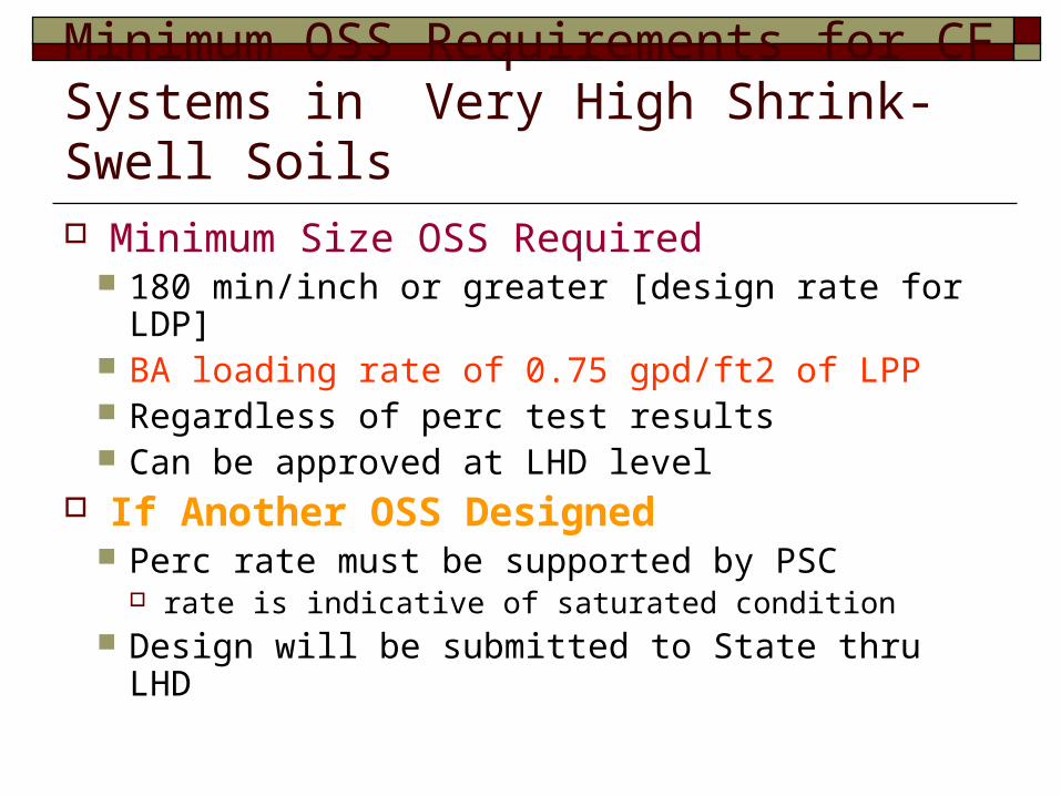
Minimum OSS Requirements for CF Systems in Very High Shrink-Swell Soils Minimum Size OSS Required
180 min/inch or greater [design rate for LDP] BA loading rate of 0.75 gpd/ft2 of LPP Regardless of perc test results Can be approved at LHD level
If Another OSS Designed Perc rate must be supported by PSC
rate is indicative of saturated condition Design will be submitted to State thru LHD

Minimum OSS Sizing for CF in High and Very High Shrink-Swell Soils Design Factors to Note
Minimum Basal Area required No “breaks” given for pipe types “Breaks” given based on treatment only
Minimum Distribution Area required Reduction can be given for type of pipe
Minimum Absorption Area required Minimum EDF Amounts required
Reduction can be given for type of pipe

Concern: High and Very High Shrink-Swell Soils
Vertisols High Clay Content [ 50 to 70 percent ] Soil Periodically Opens [forms cracks], Closes
Shrinks When Soils Become Dry Cracks = or >.2” form thru layer 10+” thick, and within 19+” of the mineral soil surface Cracks remain open for a period of 60+ consecutive days between Jun 21st & Sept 21st
Expands When Soils Become Wet [saturated] Cracks normally closed for period of 60+ consecutive days between Dec 21st & Mar 21st
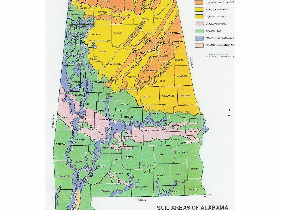
Occurs in the Black Belt and Southern Coastal Plain
Other Soils Vertic [Shrink-Swell] Characteristics
Occur Black Belt and the Upland Ridge and Valley Areas

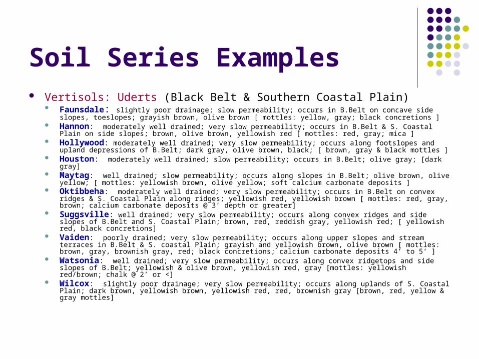
Soil Series Examples Vertisols: Uderts (Black Belt & Southern Coastal Plain)
Faunsdale: slightly poor drainage; slow permeability; occurs in B.Belt on concave side slopes, toeslopes; grayish brown, olive brown [ mottles: yellow, gray; black concretions ]
Hannon: moderately well drained; very slow permeability; occurs in B.Belt & S. Coastal Plain on side slopes; brown, olive brown, yellowish red [ mottles: red, gray; mica ]
Hollywood: moderately well drained; very slow permeability; occurs along footslopes and upland depressions of B.Belt; dark gray, olive brown, black; [ brown, gray & black mottles ]
Houston: moderately well drained; slow permeability; occurs in B.Belt; olive gray; [dark gray] Maytag: well drained; slow permeability; occurs along slopes in B.Belt; olive brown, olive yellow; [ mottles:
yellowish brown, olive yellow; soft calcium carbonate deposits ] Oktibbeha: moderately well drained; very slow permeability; occurs in B.Belt on convex ridges & S.
Coastal Plain along ridges; yellowish red, yellowish brown [ mottles: red, gray, brown; calcium carbonate deposits @ 3’ depth or greater]
Suggsville: well drained; very slow permeability; occurs along convex ridges and side slopes of B.Belt and S. Coastal Plain; brown, red, reddish gray, yellowish red; [ yellowish red, black concretions]
Vaiden: poorly drained; very slow permeability; occurs along upper slopes and stream terraces in B.Belt & S. coastal Plain; grayish and yellowish brown, olive brown [ mottles: brown, gray, brownish gray, red; black concretions; calcium carbonate deposits 4’ to 5’ ]
Watsonia: well drained; very slow permeability; occurs along convex ridgetops and side slopes of B.Belt; yellowish & olive brown, yellowish red, gray [mottles: yellowish red/brown; chalk @ 2’ or <]
Wilcox: slightly poor drainage; very slow permeability; occurs along uplands of S. Coastal Plain; dark brown, yellowish brown, yellowish red, red, brownish gray [brown, red, yellow & gray mottles]
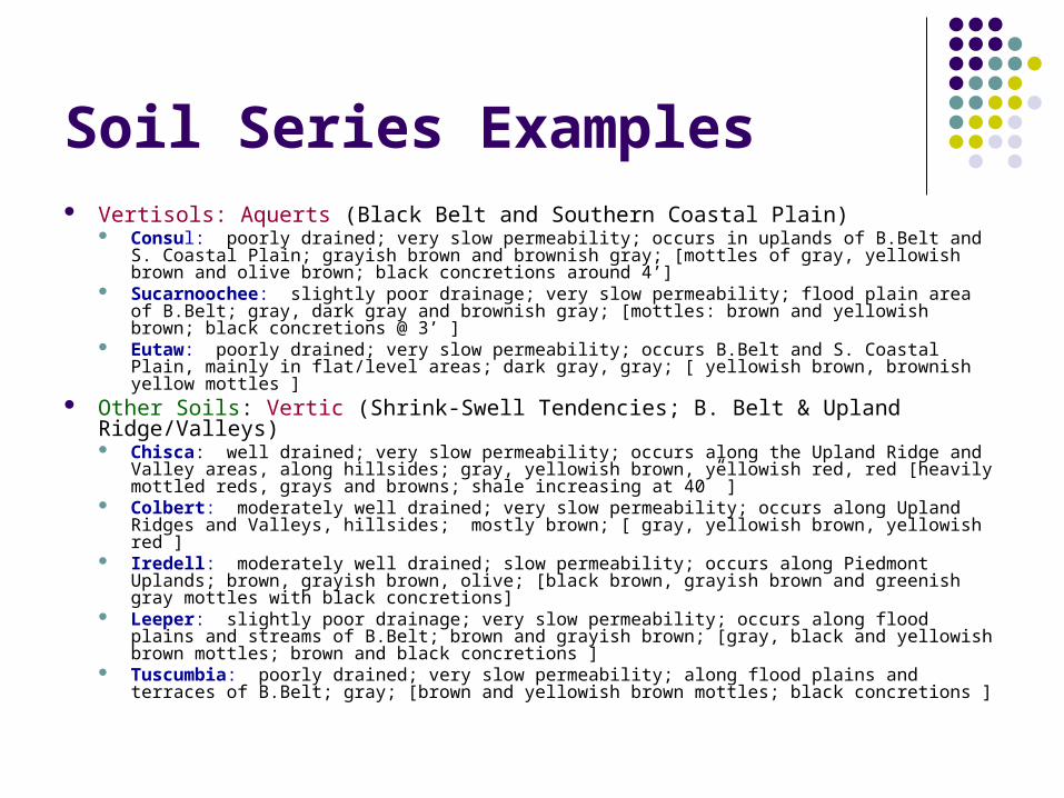
Soil Series Examples Vertisols: Aquerts (Black Belt and Southern Coastal Plain)
Consul: poorly drained; very slow permeability; occurs in uplands of B.Belt and S. Coastal Plain; grayish brown and brownish gray; [mottles of gray, yellowish brown and olive brown; black concretions around 4’]
Sucarnoochee: slightly poor drainage; very slow permeability; flood plain area of B.Belt; gray, dark gray and brownish gray; [mottles: brown and yellowish brown; black concretions @ 3’ ]
Eutaw: poorly drained; very slow permeability; occurs B.Belt and S. Coastal Plain, mainly in flat/level areas; dark gray, gray; [ yellowish brown, brownish yellow mottles ]
Other Soils: Vertic (Shrink-Swell Tendencies; B. Belt & Upland Ridge/Valleys) Chisca: well drained; very slow permeability; occurs along the Upland Ridge and Valley
areas, along hillsides; gray, yellowish brown, yellowish red, red [heavily mottled reds, grays and browns; shale increasing at 40” ]
Colbert: moderately well drained; very slow permeability; occurs along Upland Ridges and Valleys, hillsides; mostly brown; [ gray, yellowish brown, yellowish red ]
Iredell: moderately well drained; slow permeability; occurs along Piedmont Uplands; brown, grayish brown, olive; [black brown, grayish brown and greenish gray mottles with black concretions]
Leeper: slightly poor drainage; very slow permeability; occurs along flood plains and streams of B.Belt; brown and grayish brown; [gray, black and yellowish brown mottles; brown and black concretions ]
Tuscumbia: poorly drained; very slow permeability; along flood plains and terraces of B.Belt; gray; [brown and yellowish brown mottles; black concretions ]
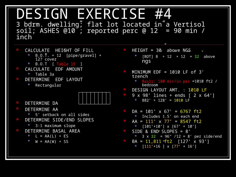
DESIGN EXERCISE #43 bdrm. dwelling; flat lot located in a Vertisol soil; ASHES @10”; reported perc @ 12” = 90 min / inch
CALCULATE HEIGHT OF FILL B.O.T. + 12” [pipe/gravel] + 12?”cover B.O.T [ Table 15 ]
CALCULATE EDF AMOUNT Table 3a
DETERMINE EDF LAYOUT Rectangular
DETERMINE DA DETERMINE AA
5’ setback on all sides DETERMINE SIDE/END SLOPES
3:1 maximum slope DETERMINE BASAL AREA
L = AA(L) + ES W = AA(W) + SS
HEIGHT = 30” above NGS [BOT] 8” + 12” + 12” = 32” above ngs
MINIMUM EDF = 1010 LF of 3’ trench Basis: 180 min/in per =1010 ft2 / bedroom
DESIGN LAYOUT AMT. : 1010 LF 9 x 98’ lines + ends [ 2 x 64’]
882’ + 128’ = 1010 LF
DA = 101’ x 67’ = 6767 ft2 Includes 1.5’ on each end
AA = 111’ x 77’ = 8547 ft2 [101’+10’] x [67’ + 10’]
SIDE & END SLOPES = 8’ 3 x 32” = 96“ /12 = 8’ per side/end
BA = 11,811 ft2 [127’ x 93’] [111’+16”] x [77’ + 16’]
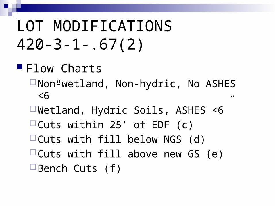
LOT MODIFICATIONS420-3-1-.67(2) Flow Charts
Non-wetland, Non-hydric, No ASHES <6”Wetland, Hydric Soils, ASHES <6”Cuts within 25’ of EDF (c)Cuts with fill below NGS (d)Cuts with fill above new GS (e)Bench Cuts (f)

Fill on Non-Wet Sites ORFill on Wetland, Hydric , Wet Sites
Amount of time fill in place Corp Approval [if applicable] Monitored weekly thru 1 wet season Site evaluated by PSC
If fill in place <3 yrs on non-hydric site<5 years on hydric, wetland site orA site with <6” to ASHES

Cuts Near EDF
Depth of Cut Proximity to EDF Discretionary Actions for LHD
Geologist ReportSoils Classifier Report
Cut With Fill Below NGS
Use Conventional OSS if possible No High Shrink/Swell Soils Underlyiing Soil Characteristics Soil Thickness Requirements & Depth to
ASHES in Soil Layer Certain Provision Included in Design
Cut With Fill Above New GS
No High Shrink/Swell Soils LHD Options
Geologist ReportPSC High Intensity Map

Bench Cuts
Type of RockHard Rock? ProhibitedOther Rock? Design Stipulations
Required ReportsGeologistPSC