OSRD Protocol for Bosch PTZ...
42
OSRD Protocol for Bosch PTZ Cameras Receiver/Drivers, G1, G2, G3, VEZ, and VG4 Series AutoDomes en Instruction Book
Transcript of OSRD Protocol for Bosch PTZ...
OSRD Protocol for Bosch PTZ CamerasReceiver/Drivers, G1, G2, G3, VEZ, and VG4 Series AutoDomes
en Instruction Book


OSRD Protocol for Bosch PTZ Cameras Table of Contents | en iii
Bosch Security Systems, Inc. Instruction Book F.01U.082.205 | 4.0 | 04.2010
Table of Contents
1 Introduction 11.1 Controlling Bosch PTZ Cameras 11.2 Numeric Designations 2
2 OSRD Commands 32.1 OSRD Message Syntax 32.1.1 Packet Length Byte 32.1.2 High Order Address Byte/Low Order Address Byte 32.1.3 Opcode 42.1.4 Data Bytes 42.1.5 Checksum 5
3 Opcode Descriptions 63.1 Standard Opcodes 63.1.1 Opcode 2 <0x02>: Start/Stop Fixed-speed PTZ, Focus, and Iris 63.1.2 Opcode 3 <0x03>: Fixed-speed PTZ for a Specified Period 63.1.3 Opcode 4 <0x04>: Repetitive Fixed-speed PTZ 73.1.4 Opcode 5 <0x05>: Start/Stop Variable-speed PTZ 83.1.5 Opcode 6 <0x06>: Repetitive Fixed-speed Zoom, Focus, and Iris 83.1.6 Opcode 7 <0x07>: Auxiliary ON/OFF and Preposition SET/SHOT Commands 93.1.7 Opcode 8 <0x08>: Repetitive Variable-speed PTZ, Focus, and Iris 103.2 Extended OSRD Commands 113.2.1 Opcode 9 <0x09>: Fine Speed PTZ 113.2.2 Opcode 10 <0x0A>: Position Report and Reply (4-byte version) 113.2.3 Opcode 10 <0x0A>: Position Commands (10-, 12-, 16-, 17-byte versions) 133.2.4 Opcode 12 <0x0C>: Ping Command (no data requested) 153.2.5 Opcode 12 <0x0C>: Ping Command (data requested) 163.2.6 Opcode 15 <0x0F>: Information Requested and Reply 173.2.7 Opcode 16 <0x10>: Title Set 213.2.8 Opcode 18 <0x12>: Auxiliary Commands with Data 213.2.9 Opcode 19 <0x13>: Set Position 253.2.10 Opcode 19 <0x13>: Get Position 28
4 Opcode 20 <0x14>: BiCom Command Interface 294.1 Data Byte Codes 304.2 BiCom Byte Descriptions 314.2.1 Server ID 314.2.2 Object/Member ID 314.2.3 Operation 314.2.4 Data Bytes 32
5 Examples 335.1 Setting the AutoPanScan Speed 335.2 Inverting the Camera Image 34

iv en | Table of Contents OSRD Protocol for Bosch PTZ Cameras
F.01U.082.205 | 4.0 | 04.2010 Instruction Book Bosch Security Systems, Inc.
6 Appendix: Hardware Configuration 35
7 Appendix: Opcode Usage 36

OSRD Protocol for Bosch PTZ Cameras Introduction | en 1
Bosch Security Systems, Inc. Instruction Book F.01U.082.205 | 4.0 | 04.2010
1 IntroductionThis manual describes the On-site Receiver/Driver (OSRD) protocol that transfers messages over a serial connection to a pan/tilt/zoom device (for example a Bosch receiver/driver). This manual describes the message structure, command structure, and the values for the parameters that comprise the message. If you are not familiar with these protocols, you can use this manual to learn the syntax and capabilities of OSRD. It is recommended, however, that you understand API programming concepts and bit manipulation. The electrical interface of this protocol is typically RS-232 or Bosch Biphase.
1.1 Controlling Bosch PTZ CamerasThe OSRD protocol utilizes Opcodes to determine the actual function to be executed by the receiver/driver. The original OSRD protocol contained seven Opcodes. With the introduction of the G3 Series AutoDome, the OSRD protocol was extended to include nine new Opcodes to control the new pan/tilt/zoom features of the G3 AutoDome.The VG4 Series AutoDome supports the original seven OSRD Opcodes, and a more recent protocol called BiCom. BiCom provides equivalent functionality as that of the extended OSRD opcodes. To use the BiCom commands within and OSRD message packet, the controller device uses Opcode 20 <0x14> to send a BiCom command within an OSRD packet.The following table summarizes the control code protocols and the products that support each:
1. The G3 and VG4 series AutoDomes do not support all commands available in Opcode 7. The Aux Toggle,
Aux On Latch, Aux Off Latch, and the Cancel Latch Aux commands are not supported.
2. The initial firmware version of LTC 8016 does not support the recent Aux commands found in Dinion series
cameras.
For a complete list of controllers, functions, and supported Opcodes, see Section 7 Appendix: Opcode Usage, page 36.
Protocol PTZ DeviceVG4
AutoDomeVEZ
AutoDome EasyG3
AutoDomeG2
AutoDomeG1
AutoDomeLTC 8016 Receiver/
DriverOSRD– Opcode 2 <0x02> • • • • • • •– Opcode 3 <0x03> • • • • •– Opcode 4 <0x04> • • • • • •– Opcode 5 <0x05> • • • • • • •– Opcode 6 <0x06> • • • • • •– Opcode 7 <0x07> •1 • •1 • • •2 •– Opcode 8 <0x08> • • • • • • •OSRD Extended– Opcode 9 <0x09> • •– Opcode 10 <0x0A> • •– Opcode 12 <0x0C> •– Opcode 15 <0x0F> •– Opcode 16 <0x10> •– Opcode 18 <0x12> •– Opcode 19 <0x13> • •BiCom within OSRD– Opcode 20 <0x14> •BiCom •
2 en | Introduction OSRD Protocol for Bosch PTZ Cameras
F.01U.082.205 | 4.0 | 04.2010 Instruction Book Bosch Security Systems, Inc.
1.2 Numeric DesignationsThe OSRD protocol specifies that numeric data represent the components of a command message packet. Most of the numeric data is represented as hexadecimal numbers, but some of the actual data values are expressed as decimal numbers. This manual uses the following conventions to distinguish between hexadecimal and decimal numbers:– The value “25” is interpreted as a decimal value.– The value “0x25” is interpreted as a hexadecimal value.

OSRD Protocol for Bosch PTZ Cameras Introduction | en 3
Bosch Security Systems, Inc. Instruction Book F.01U.082.205 | 4.0 | 04.2010
2 OSRD CommandsControl code data is sent in message packets. For certain functions, commands must be sent repetitively at a rate of 20 Hz to maintain a smooth operational response of the device being driven by the receiver/driver. See Section 6 Appendix: Hardware Configuration, page 35, for more information on hardware configuration.The general format of an OSRD command is:
2.1 OSRD Message SyntaxThe following sections describe the attributes of the required information for each data byte position above.
2.1.1 Packet Length ByteEach packet begins with a Length byte that specifies the number of bytes in the remainder of the packet (the Length byte itself is not included in this number). The most significant bit (MSB) of the Length byte is always set to 1. The MSB must be zero for ALL other bytes of the message packet. For the functions below, only control commands with lengths of 6 and 7 bits are used, therefore, the Length byte (with the MSB set) will be either 0x86 or 0x87.
2.1.2 High Order Address Byte/Low Order Address ByteThe message packet contains a device (VG4, G3, G2, or G1 AutoDome and Receiver/Driver) address number encoded using a 14-bit binary value. (Including an address value permits the data to be broadcast to all receiver/driver sites but only the site set to a matching address will respond.) This address number is sent using 2 bytes of the message packet. The binary value corresponds to the logical camera number of the camera site being controlled minus 1. The High Order Address byte consists of the upper 7 bits of the 14-bit binary camera number. The Low Order Address byte consists of the lower 7 bits of the 14-bit binary camera number. In all cases, the MSB of each byte is not counted as part of the address number and must always be reset to zero so it will not be confused with the Length byte. Since the use of a 14-bit binary number provides a camera number range from 1 to 16384, the corresponding device Address data bytes would take the form of 0x0000 to 0x7F7F.The High Order Byte (the upper 7 bits of the 14-bit binary camera number) is used for cameras with an address greater than 127. Use the Low Order Byte (the lower 7 bits of the 14-bit binary camera number) for cameras with an address of 1 to 127.For example, camera number 1 is encoded with all 14 data bits reset to zero. Camera number 2 has its Least Significant Bit (LSB) set to 1 and all other bits set to zero. The table below provides examples of Address Bytes:
Byte Bit 7 Bit 6 Bit 5 Bit 4 Bit 3 Bit 2 Bit 1 Bit 00x00 1 Packet Length Byte0x01 0 High Order Address byte (upper 7 bits of a 14-bit camera number)0x02 0 Low Order Address byte (lower 7 bits of a 14-bit camera number)0x03 0 Opcode0x04 0 Data Byte 10x05 0 Data Byte 20x0N 0 Data Byte N0xN+1 0 Checksum of all previous bytes (lower 7 bits only)

4 en | Introduction OSRD Protocol for Bosch PTZ Cameras
F.01U.082.205 | 4.0 | 04.2010 Instruction Book Bosch Security Systems, Inc.
2.1.3 OpcodeDefines the type of data packet. See Section 3 Opcode Descriptions, page 6, for details about each Opcode. Use Opcode 20 (0x14) to send a BiCom API message to a VG4 AutoDome.
2.1.4 Data BytesEach Opcode requires a specific number of data byte fields. The data bytes determine the function that the controller device sends to the head-end device. Refer to the specific Opcode description below for the appropriate number of data byte fields and for the appropriate values for the fields.A data byte consists of a 7-bit (bit positions 0 through 6) word; Bosch reserves the MSB (bit position 7). Bit position 7 is not used when you specify a value in the data byte. By ignoring bit position 7, the decimal value of bit position 7 (128) is shifted to bit position 0 of the second data byte.Certain data values require more than one data byte to express the value; therefore you must split a full binary value (maximum of 13 bits) into a high-order data byte value and a low-order data byte value. The low-order data byte consists of bit numbers 0-6 (bit number 7 is not used). The high-order data byte consists of bit numbers 7-12. The following table shows the bit positions for a high-order and for a low-order data byte with their corresponding bit numbers and decimal values:
Camera Number Encoded Value 14-bit Binary Value High Order Byte Low Order Byte 1 0 0000000 0000000 0x00 0x002 1 0000000 0000001 0x00 0x01
128 127 0000000 1111111 0x00 0x7F129 128 0000001 0000000 0x80 0x00256 255 0000001 1111111 0x01 0x7F257 256 0000010 0000000 0x02 0x00500 499 0000011 1110011 0x03 0x73512 511 0000011 1111111 0x03 0x7F513 512 0000100 0000000 0x04 0x001024 1023 0000111 1111111 0x07 0x7F5000 4999 0100111 0000111 0x27 0x079999 9998 1001110 0001110 0x4E 0x0E16384 16383 1111111 1111111 0x7F 0x7F
Bit Position
7 6 5 4 3 2 1 0
Data Byte 1
(High-order)
Bit Number 12 11 10 9 8 7
Decimal Value 4096 2048 1024 512 256 128
Bit Position
7 6 5 4 3 2 1 0
Data Byte 2
(Low-order)
Bit Number 6 5 4 3 2 1 0
Decimal Value 64 32 16 8 4 2 1

OSRD Protocol for Bosch PTZ Cameras Introduction | en 5
Bosch Security Systems, Inc. Instruction Book F.01U.082.205 | 4.0 | 04.2010
2.1.5 ChecksumCalculate the sum of each 8-bit number (including the Length byte) for the entire command syntax using mod 0x7F. To calculate the checksum value, convert any binary numbers into a hexadecimal value. For example, using a scientific calculator, add each hexidecimal message packet value to arrive at the message packet subtotal. Once you have the subtotal, use the bitwise AND operator to apply 0x7F to the subtotal to arrive at the checksum value. For example, if the message packet consists of:0x8B 0x00 0x00 0x14 0x00 0x60 0x01 0x01 0x02 0x00 0x01 0x04
to calculate the checksum, use the following formula (all values are expressed in hexadecimal):(8B+00+00+14+00+60+01+01+02+00+01) AND 7F = 0x04

6 en | Introduction OSRD Protocol for Bosch PTZ Cameras
F.01U.082.205 | 4.0 | 04.2010 Instruction Book Bosch Security Systems, Inc.
3 Opcode DescriptionsThis section describes the standard and the extended set of OSRD Opcode commands. The standard set of Opcodes consists of Opcodes 2 <0x02> through 8 <0x08> (Opcode 1 <0x01> is not used) and are available for all Receiver/Drivers and G1, G2, G3 Series AutoDomes. For VG4 Series AutoDomes, Opcode <0x02> and Opcodes <0x04> through <0x08> are available, the VG4 Series does not support Opcode <0x03>.The extended set consists of Opcodes 9 <0x09>, 10 <0x0A>, 12 <0x0C>, 15 <0x0F>, 16 <0x10>, 18 <0x12>, Opcode 19 <0x13>, and Opcode 20 <0x14>. The entire extended set is available for G3 AutoDomes, version 5.00 or higher, only. VG4 Series AutoDomes support Opcodes 9 <0x09>, 10 <0x0A>, 9 <0x13>, and 20 <0x14> only.In all cases, a 1 written into a bit position initiates the specified action. If conflicting bits are set (e.g., Pan Left and Pan Right), the action is undefined, but the device resolves the conflict with no damage. If the device receives a command while still processing a previous command, the old command is aborted, and the new one executed. To issue the corresponding command with a VG4 Series AutoDome, use Opcode 20 (0x14). see Section 4 Opcode 20 <0x14>: BiCom Command Interface, page 29.
3.1 Standard OpcodesThe standard Opcodes are the original OSRD Opcodes and are available for all Bosch AutoDome models and Receiver/Drivers. Each Opcode sends a command to a device for a specified period of time, which is referenced in the title of the Opcode in the following way:– Start/Stop: The command is in effect until a controller device sends a stop command.– Repetitive: The device controller must send the same command within a specified period
of time or the camera ceases the command function.
3.1.1 Opcode 2 <0x02>: Start/Stop Fixed-speed PTZ, Focus, and IrisOpcode 2 <0x02> activates fixed-speed pan/tilt/zoom functions for an indefinite period. A logical 1 (one) activates the indicated function, which remains active until explicitly turned off. The functions can be turned off by a command with a different Opcode or by Opcode 2 <0x02> with a 0 (zero) in the associated data bit position.
– An X indicates that the bit position is not used.– A value of 1 (one) in a bit position starts the operation.– A value of 0 (zero) in a bit position stops the operation.
3.1.2 Opcode 3 <0x03>: Fixed-speed PTZ for a Specified PeriodOpcode 3 <0x03> is referred to as the “poor man's preposition” because it can be used to operate any pan/tilt/zoom device (even those without preposition capability) to approximate positions by moving for a specified time in the desired direction. The duration of the function is specified using a 6-bit data value where the time is specified in units of half-seconds. This provides a time range of 1/2 second duration (all bits reset to zero) to 32 seconds (all bits set to 1). Note that the actual duration of the function may only approximate the specified time due to conditions at the receiver/driver site.Note: Opcode 3 <0x03> is available for G3, G2, G1 Series AutoDomes, LTC 8016, and for Receivers/Drivers.
Command <0x86><Address MSB><Address LSB><0x02><Data Byte 1><Data Byte 2><checksum>
Data Byte Codes7 6 5 4 3 2 1 0
Data Byte 1 0 X X Pan Left Tilt Up Zoom Out Focus Near Iris Brighter
Data Byte 2 0 X X Pan Right Tilt Down Zoom In Focus Far Iris Darker

OSRD Protocol for Bosch PTZ Cameras Introduction | en 7
Bosch Security Systems, Inc. Instruction Book F.01U.082.205 | 4.0 | 04.2010
– A value of 1 (one) in a bit position starts the operation.– A value of 0 (zero) in a bit position stops the operation.– The operation continues for the time specified in bits 1 through 5 or until stopped by this
or another Opcode.
3.1.3 Opcode 4 <0x04>: Repetitive Fixed-speed PTZOpcode 4 <0x04> activates pan/tilt/zoom functions at a fixed speed determined by the Receiver/Driver or by the AutoDome. This Opcode activates the specified function for at least 50 ms, so the command must be issued at a frequency of no less than 20 Hz for smooth operation.
– An X indicates that the bit position is not used.– A value of 1 (one) in a bit position starts the operation.– A value of 0 (zero) in a bit position stops the operation.
Command <0x86><Address MSB><Address LSB><0x03><Data Byte 1><Data Byte 2><checksum>
Data Byte Codes7 6 5 4 3 2 1 0
Data Byte 1 0 Duration Bit
5
Duration Bit
4
Duration Bit 3
Duration Bit
2
Duration Bit
1
Duration Bit
0
Focus Far
Data Byte 2 0 Focus Near Zoom In Zoom Out Tilt Up Tilt Down Pan Left Pan Right
Command <0x86><Address MSB><Address LSB><0x04><Data Byte 1><Data Byte 2><checksum>
Data Byte Codes7 6 5 4 3 2 1 0
Data Byte 1 0 X X X 1 1 1 Focus Far
Data Byte 2 0 Focus Near Zoom In Zoom Out Tilt Up Tilt Down Pan Left Pan Right

8 en | Introduction OSRD Protocol for Bosch PTZ Cameras
F.01U.082.205 | 4.0 | 04.2010 Instruction Book Bosch Security Systems, Inc.
3.1.4 Opcode 5 <0x05>: Start/Stop Variable-speed PTZOpcode 5 <0x05> activates variable-speed functions for an indefinite period. A logic one activates the indicated function, which remains active until explicitly turned off. The appropriate Speed Bits determine the speed for the Pan, Tilt, and Zoom operations. The Receiver/Driver settings determine the Focus and Iris speed. The functions can be turned off by a command with a different Opcode or by Opcode 5 <0x05> with a zero in the associated data bit position.
– An X indicates that the bit position is not used.– A value of 1 (one) in a bit position starts the operation.– A value of 0 (zero) in a bit position stops the operation.
3.1.5 Opcode 6 <0x06>: Repetitive Fixed-speed Zoom, Focus, and IrisOpcode 6 <0x06> activates the zoom, focus, and iris functions at a fixed speed determined by the Receiver/Driver or by the AutoDome. This Opcode causes the specified function to be activated for at least 50 ms, so the command must be issued at a frequency of no less than 20 Hz for smooth operation.
– An X indicates that the bit position is not used.– A value of 1 (one) in a bit position starts the operation.– A value of 0 (zero) in a bit position stops the operation.
Command <0x86><Address MSB><Address LSB><0x05><Data Byte 1><Data Byte 2><Data Byte 3> <checksum>
Data Byte Codes7 6 5 4 3 2 1 0
Data Byte 1 0 Zoom Speed Bit
2
Zoom Speed Bit
1
Zoom Speed Bit
0
Tilt Speed
Bit 3
Tilt Speed
Bit 2
Tilt Speed
Bit 1
Tilt Speed
Bit 0
Data Byte 2 0 Pan Speed
Bit 3
Pan Speed
Bit 2
Pan Speed
Bit 1
Pan Speed
Bit 0
Iris Brighter Iris Darker Focus Far
Data Byte 3 0 Focus Near Zoom In Zoom Out Tilt Up Tilt Down Pan Left Pan Right
Command <0x86><Address MSB><Address LSB><0x06><Data Byte 1><Data Byte 2><checksum>
Data Byte Codes7 6 5 4 3 2 1 0
Data Byte 1 0 X X X X X X XData Byte 2 0 X Iris
BrighterIris Darker Focus Far Focus Near Zoom In Zoom Out

OSRD Protocol for Bosch PTZ Cameras Introduction | en 9
Bosch Security Systems, Inc. Instruction Book F.01U.082.205 | 4.0 | 04.2010
3.1.6 Opcode 7 <0x07>: Auxiliary ON/OFF and Preposition SET/SHOT CommandsOpcode 7 <0x07> activates preposition or auxiliary functions. The numeric data consists of a 10-bit binary number. The upper 3 bits of this 10-bit number along with the desired function is sent as Data Byte 1. The lower 7 bits of the 10-bit number is sent as Data Byte 2. The Auxiliary On and Off commands are sometimes issued repetitively to control level adjustment functions.
– Data Bits 0 through 9 specify the Auxiliary Number or the Pre-position Number, with available values from 0 through 1023.
– Function Code Bits 0 through 3 specify the type of operation as defined in the following table.
Command <0x86><Address MSB><Address LSB><0x07><Data Byte 1><Data Byte 2><checksum>
Data Byte Codes7 6 5 4 3 2 1 0
Data Byte 1 0 Data Bit 9 Data Bit 8
Data Bit 7 Function Code Bit 3
Function Code Bit 2
Function
Code Bit 1
Function Code Bit 0
Data Byte 2 0 Data Bit 6 Data Bit 5
Data Bit 4 Data Bit 3 Data Bit 2 Data Bit 1 Data Bit 0
Function Code Bits 0–3
Function Data Bits 0–9 Description
0000 Reserved Undefined Not used0001 Auxiliary ON Auxiliary Number ON–Auxiliary_Number–ENTER0010 Auxiliary OFF Auxiliary Number OFF–Auxiliary_Number–ENTER00110100 Pre-position SET Pre-position Number SET–Pre-position_Number–ENTER0101 Pre-position SHOT Pre-position Number SHOT–Pre-position_Number–ENTER0110 Reserved Undefined Not Used0111 Reserved Undefined Not Used1000 Cancel Latching Aux Undefined Latching Auxiliary ON and OFF
functions are used to activate the auxiliary function until explicitly deactivated using the Cancel Latching Aux command.
1001 Latching Aux ON Auxiliary Number1010 Latching Aux OFF Auxiliary Number
1011 Reserved Undefined Not Used1100 Reserved Undefined Not Used1101 Reserved Undefined Not Used1110 Reserved Undefined Not Used1111 Reserved Undefined Not Used

10 en | Introduction OSRD Protocol for Bosch PTZ Cameras
F.01U.082.205 | 4.0 | 04.2010 Instruction Book Bosch Security Systems, Inc.
3.1.7 Opcode 8 <0x08>: Repetitive Variable-speed PTZ, Focus, and IrisOpcode 8 <0x08> activates pan, tilt, zoom, focus, and iris functions. It provides for variable speed control over pan/tilt/zoom functions. The pan and tilt functions require a speed value of 0 to 15; 0 is the slowest speed and 15 is the fastest speed. The zoom function requires a speed value of 0 to 7; 0 is the slowest speed and 7 is the fastest speed. This Opcode causes the specified function to be activated for at least 50 ms, so the command must be issued at a frequency of no less than 20 Hz for smooth operation.
– A value of 1 (one) in a bit position starts the operation.– A value of 0 (zero) in a bit position stops the operation.– The appropriate Speed Bits determine the speed for the pan, tilt, and zoom operations.– The Receiver/Driver settings determine the speed for the focus and iris operations.
Command <0x86><Address MSB><Address LSB><0x08><Data Byte 1><Data Byte 2><Data Byte 3> <checksum>
Data Byte Codes7 6 5 4 3 2 1 0
Data Byte 1 0 Zoom Speed Bit
2
Zoom Speed Bit
1
Zoom Speed Bit
0
Tilt Speed Bit
3
Tilt Speed Bit 2
Tilt Speed
Bit 1
Tilt Speed Bit
0Data Byte 2 0 Pan Speed
Bit 3
Pan Speed
Bit 2
Pan Speed
Bit 1
Pan Speed
Bit 0
Iris Brighter Iris Darker Focus Far
Data Byte 3 0 Focus Near Zoom In Zoom Out Tilt Up Tilt Down Pan Left Pan Right
OSRD Protocol for Bosch PTZ Cameras Introduction | en 11
Bosch Security Systems, Inc. Instruction Book F.01U.082.205 | 4.0 | 04.2010
3.2 Extended OSRD CommandsThe Extended set of OSRD commands (Opcodes 9 <0x09>, 10 <0x0A>, 12 <0x0C>, 15 <0x0F>, 16 <0x10>, 18 <0x12>, and 19 <0x13) is available only for G3 AutoDomes version 5.00 or higher. VG4 Series AutoDomes support Opcodes 9 <0x09>, 10 <0x0A>, 19 <0x13>, and20 <0x14> only.
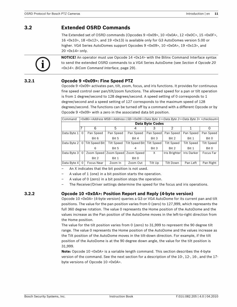
3.2.1 Opcode 9 <0x09>: Fine Speed PTZOpcode 9 <0x09> activates pan, tilt, zoom, focus, and iris functions. It provides for continuous fine speed control over pan/tilt/zoom functions. The allowed speed for a pan or tilt operation is from 1 degree/second to 128 degrees/second. A speed setting of 0 corresponds to 1 degree/second and a speed setting of 127 corresponds to the maximum speed of 128 degrees/second. The functions can be turned off by a command with a different Opcode or by Opcode 9 <0x09> with a zero in the associated data bit position.
– An X indicates that the bit position is not used.– A value of 1 (one) in a bit position starts the operation.– A value of 0 (zero) in a bit position stops the operation.– The Receiver/Driver settings determine the speed for the focus and iris operations.
3.2.2 Opcode 10 <0x0A>: Position Report and Reply (4-byte version)Opcode 10 <0x0A> (4-byte version) queries a G3 or VG4 AutoDome for its current pan and tilt positions. The value for the pan position varies from 0 (zero) to 127,999, which represents the full 360 degree rotation. The value 0 represents the Home position of the AutoDome and the values increase as the Pan position of the AutoDome moves in the left-to-right direction from the Home position.The value for the tilt position varies from 0 (zero) to 31,999 to represent the 90 degree tilt range. The value 0 represents the Home position of the AutoDome and the values increase as the Tilt position of the AutoDome moves in the tilt-down direction. For example, if the tilt position of the AutoDome is at the 90 degree down angle, the value for the tilt position is 31,999.Note: Opcode 10 <0x0A> is a variable length command. This section describes the 4-byte version of the command. See the next section for a description of the 10-, 12-, 16-, and the 17-byte versions of Opcode 10 <0x0A>.
iNOTICE! An operator must use Opcode 14 <0x14> with the Bilinx Command Interface syntax to send the extended OSRD commands to a VG4 Series AutoDome (see Section 4 Opcode 20 <0x14>: BiCom Command Interface, page 29).
Command <0x86><Address MSB><Address LSB><0x09><Data Byte 1><Data Byte 2><Data Byte 3> <checksum>
Data Byte Codes7 6 5 4 3 2 1 0
Data Byte 1 0 Pan Speed
Bit 6
Pan Speed
Bit 5
Pan Speed
Bit 4
Pan Speed
Bit 3
Pan Speed
Bit 2
Pan Speed
Bit 1
Pan Speed
Bit 0
Data Byte 2 0 Tilt Speed Bit
6
Tilt Speed
Bit 5
Tilt Speed Bit
4
Tilt Speed
Bit 3
Tilt Speed
Bit 2
Tilt Speed
Bit 1
Tilt Speed
Bit 0
Data Byte 3 0 Zoom Speed
Bit 2
Zoom Speed
Bit 1
Zoom Speed
Bit 0
X Iris Brighter Iris Darker Focus Far
Data Byte 4 0 Focus Near Zoom In Zoom Out Tilt Up Tilt Down Pan Left Pan Right

12 en | Introduction OSRD Protocol for Bosch PTZ Cameras
F.01U.082.205 | 4.0 | 04.2010 Instruction Book Bosch Security Systems, Inc.
– A value of 1 (one) in a bit position starts the operation.– A value of 0 (zero) in a bit position stops the operation.– The Receiver/Driver settings determine the speed for the focus and iris operations.
Command <0x84><Address MSB><Address LSB><0x0A><checksum>
Response Data Byte Codes7 6 5 4 3 2 1 0
Pan Position
Data Byte 1
0 0 0 0 0 Pan Position
Bit 16
Pan Position
Bit 15
Pan Position
Bit 14
Pan Position
Data Byte 2
0 Pan Position
Bit 13
Pan Position
Bit 12
Pan Position
Bit 11
Pan Position
Bit 10
Pan Position
Bit 9
Pan Position
Bit 8
Pan Position
Bit 7
Pan Position
Data Byte 3
0 Pan Position
Bit 6
Pan Position
Bit 5
Pan Position
Bit 4
Pan Position
Bit 3
Pan Position
Bit 2
Pan Position
Bit 1
Pan Position
Bit 0
Tilt Position
Data Byte 1
0 0 0 0 0 0 0 Tilt Position
Bit 14
Tilt Position
Date Byte 2
0 Tilt Position
Bit 13
Tilt Position
Bit 12
Tilt Position
Bit 11
Tilt Position
Bit 10
Tilt Position
Bit 9
Tilt Position
Bit 8
Tilt Position
Bit 7
Tilt Position
Data Byte 3
0 Tilt Position
Bit 6
Tilt Position
Bit 5
Tilt Position
Bit 4
Tilt Position
Bit 3
Tilt Position
Bit 2
Tilt Position
Bit 1
Tilt Position
Bit 0
Reply <length byte w/Bit7 set><Address MSB><Address LSB><0x87><0x0A>
<Pan Position Data Byte 1><Pan Position Data Byte 2> <Pan Position Data Byte 3>
<Tilt Position Data Byte 1><Tilt Position Data Byte 2><Tilt Position Data Byte 3><checksum>

OSRD Protocol for Bosch PTZ Cameras Introduction | en 13
Bosch Security Systems, Inc. Instruction Book F.01U.082.205 | 4.0 | 04.2010
3.2.3 Opcode 10 <0x0A>: Position Commands (10-, 12-, 16-, 17-byte versions)Opcode 10 <0x0A> (the 10-, 12-, 16-, and the 17-byte version) commands a G3 or VG4 AutoDome to move to an absolute position at a specified velocity and acceleration. This Opcode also commands the device to set the absolute positions for the zoom, focus, and the iris functions. The value for the pan position varies from 0 (zero) to 127,999, which represents the full 360 degree rotation. The value 0 represents the Home position of the AutoDome and the values increase as the Pan position of the AutoDome moves in the left-to-right direction from the Home position.The value for the tilt position varies from 0 (zero) to 31,999 to represent the 90 degree tilt range. The value 0 represents the Home position of the AutoDome and the values increase as the Tilt position of the AutoDome moves in the tilt-down direction. For example, if the tilt position of the AutoDome is at the 90 degree down angle, the value for the tilt position is 31,999.The acceptable values for the pan and tilt velocities and for the pan and tilt accelerations are from 0 through 7. The velocity values represent evenly spaced speeds from 10 degrees/second to 130 degrees/second, while the acceleration values represent evenly spaced
acceleration from 10 degrees/second2 to 130 degrees/second2. The device ignores the Velocity/Acceleration values, however, if the value for the Velocity/Acceleration Ignore Bit is set to 1. In addition to the pan and tilt settings, Opcode 10 <0x0A> allows an operator to set the values for the zoom, focus, iris, backlight compensation, AGC, and the white balance functions. The following table summarizes the values for these functions:
Note: Opcode 10 <0x0A> is a variable length command. This section describes the 10-, 12-, 16-, and the 17-byte versions of the command. See the previous section for a description of the 4-byte version of Opcode 10 <0x0A>.
Function Values ExplanationZoom Range of 0x4 to 0xAA or 0xFF OxFF instructs the unit to ignore any
setting for the particular function.Focus Range of 0x8 to 0xFE or OxFFIris Range of 0x31 to 0xCF or 0xFFAutoFocus 0 (zero) or 1 0 deactivates the function.
1 activates the function.AutoIris 0 (zero) or 1Backlight Compensation 0 (zero) or 1AGC 0 (zero) or 1White Balance 0x00 Sets white balance to Automatic.
0x01 Sets white balance to Indoor.0x10 Sets white balance to Outdoor.0x11 Sets white balance to One-push.

14 en | Introduction OSRD Protocol for Bosch PTZ Cameras
F.01U.082.205 | 4.0 | 04.2010 Instruction Book Bosch Security Systems, Inc.
Command IF 10-byte length, ADD:
<0x8A>…
ELSE
IF 12-byte length ADD:
<0x9C>…
ELSE
IF 16-byte length ADD:
<0x90>
… ELSE
IF 17-byte length ADD:
<0x91>…
;
THEN ADD
<Address MSB><Address LSB><0x0A><Pan Position Data Byte 1><Pan Position Data Byte
2><Pan Position Data Byte 3><Tilt Position Data Byte 1>
<Tilt Position Data Byte 2><Tilt Position Data Byte 3>…
THEN
IF Length >= 12 bytes; ADD
<PanVelocity/Acceleration Data Byte><TiltVelocity/Acceleration Data Byte>…
THEN
IF Length >= 16 bytes; ADD
<Zoom/Focus/Iris Configuration and LSBs>Zoom Position Data Byte>
<Focus Position Data Byte><Iris Position Data Byte>…
THEN
IF Length >= 17 bytes; ADD
<Camera Setting Data Byte>
… ELSE ADD (for all lengths)
<checksum>Data Byte Codes (as required by the number of bytes)
7 6 5 4 3 2 1 0Pan Position
Data Byte 1
0 Pan Position
Ignore Bit
0 0 0 Pan Position
Bit 16
Pan Position
Bit 15
Pan
Position Bit
14
Pan Position
Data Byte 2
0 Pan Position
Bit 13
Pan Position
Bit 12
Pan Position
Bit 11
Pan Position
Bit 10
Pan Position
Bit 9
Pan Position
Bit 8
Pan
Position Bit
7
Pan Position
Data Byte 3
0 Pan Position
Bit 6
Pan Position
Bit 5
Pan Position
Bit 4
Pan Position
Bit 3
Pan Position
Bit 2
Pan Position
Bit 1
Pan
Position Bit
0
Tilt Position
Data Byte 1
0 Tilt Position
Ignore Bit
0 0 0 0 0 Tilt Position
Bit 14
Tilt Position
Date Byte 2
0 Tilt Position
Bit 13
Tilt Position
Bit 12
Tilt Position
Bit 11
Tilt Position
Bit 10
Tilt Position
Bit 9
Tilt Position
Bit 8
Tilt Position
Bit 7
Tilt Position
Data Byte 3
0 Tilt Position
Bit 6
Tilt Position
Bit 5
Tilt Position
Bit 4
Tilt Position
Bit 3
Tilt Position
Bit 2
Tilt Position
Bit 1
Tilt Position
Bit 0
Pan Velocity/
Acceleration
Data Byte
0 Pan Velocity/
Accel. Ignore
Bit
Pan Accel.
Bit 2
Pan Accel.
Bit 1
Pan Accel.
Bit 0
Pan Velocity
Bit 2
Pan Velocity
Bit 1
Pan Velocity
Bit 0
Tilt Velocity/
Acceleration
Data Byte
0 Tilt Velocity/
Accel. Ignore
Bit
Tilt Accel.
Bit 2
Tilt Accel.
Bit 1
Tilt Accel.
Bit 0
Tilt Velocity
Bit 2
Tilt Velocity
Bit 1
Tilt Velocity
Bit 0

OSRD Protocol for Bosch PTZ Cameras Introduction | en 15
Bosch Security Systems, Inc. Instruction Book F.01U.082.205 | 4.0 | 04.2010
3.2.4 Opcode 12 <0x0C>: Ping Command (no data requested)Opcode 12 <0x0C> queries the G3 AutoDome to establish communications. When the device receives a query with a ping type of 0 (zero) it responds with the reply in the table below. The device returns no other data.
Lens Mode
and LSB
0 X Auto Iris Bit Auto Focus
Bit
X Zoom
Position Bit
0
Focus
Position Bit
0
Iris Position
Bit 0
Zoom
Position Data
Byte
0 Zoom
Position Bit
7
Zoom
Position Bit
6
Zoom
Position Bit
5
Zoom
Position Bit
4
Zoom
Position Bit
3
Zoom
Position Bit
2
Zoom
Position Bit
1
Focus
Position Data
Byte
0 Focus
Position Bit
7
Focus
Position Bit
6
Focus
Position Bit
5
Focus
Position Bit
4
Focus
Position Bit
3
Focus
Position Bit
2
Focus
Position Bit
1
Iris Position
Data Byte
0 Iris Position
Bit 7
Iris Position
Bit 6
Iris Position
Bit 5
Iris Position
Bit 4
Iris Position
Bit 3
Iris Position
Bit 2
Iris Position
Bit 1
Camera
Settings Data
Byte
0 X X X Backlight
Comp. Bit
AGC Bit White
Balance Bit
1
White
Balance Bit
0
Command <0x86><Address MSB><Address LSB><0x0C><0x00 (ping type)>
<Data Requested Data Byte><checksum>
Data Byte Codes7 6 5 4 3 2 1 0
Ping Type
Data Byte
0 Ping Type 0x00
Data
Requested
Data Byte
0 Query Camera
Settings Bit
Query Lens
Mode and
LSB Data Bit
Query Iris
Position Bit
Query Focus
Position Bit
Query Zoom
Position Bit
Query Tilt
Position Bit
Query Pan
Position Bit
Reply <length byte w/Bit7 set><Address MSB><Address LSB><0x4C><0x00><0x00><0x00><0x00>
<checksum>

16 en | Introduction OSRD Protocol for Bosch PTZ Cameras
F.01U.082.205 | 4.0 | 04.2010 Instruction Book Bosch Security Systems, Inc.
3.2.5 Opcode 12 <0x0C>: Ping Command (data requested)Opcode 12 <0x0C>, with data requested, queries the G3 AutoDome for the values of the settings as determined in the Received Command. When the device receives a query with a ping type of 1 it responds with the reply in the table below. The data that this Opcode receives is summarized in this table:
Function Values ExplanationPan Position 0 (zero) through 127,999 0 represents the Home position of the
AutoDome. Values increase as the Pan position of the AutoDome moves in the left-to-right direction from the Home position.
Tilt Position 0 (zero) through 31,999 0 represents the Home position of the AutoDome.Values increase as the Pan position of the AutoDome moves in the left-to-right direction from the Home position.
Zoom Range of 0x04 to 0xAAFocus Range of 0x08 to 0xFEIris Range of 0x31 to 0xCFAutoFocus 0 (zero) or 1 0 indicates the function is deactivated.
1 indicates the function is activate.AutoIris 0 (zero) or 1Backlight Compensation 0 (zero) or 1AGC 0 (zero) or 1White Balance 0x00 White balance is set to Automatic.
0x01 White balance is set to Indoor.0x10 White balance is set to Outdoor.0x11 White balance is set to One-push.

OSRD Protocol for Bosch PTZ Cameras Introduction | en 17
Bosch Security Systems, Inc. Instruction Book F.01U.082.205 | 4.0 | 04.2010
3.2.6 Opcode 15 <0x0F>: Information Requested and ReplyOpcode 15 <0x0F> queries a G2 or G3 AutoDome to obtain information about the device. The amount and type of information returned depends on the structure of the message. The message may contain requests for specific values contained in these three categories:– Data Requested: AutoTrack, AutoDome Information Request, Special Tracking Mode, and
AutoTrack Frequency– AutoDome Data: Receiver/Driver or Camera Type, Receiver/Driver Software Version, Line
Lock Delay, Camera Settings, and E-Zoom– Tracking Components: Camera Data, Lens Mode and LSB, Iris Position, Focus Position,
Zoom Position, Tilt Position, and Pan Position.
Command <0x86><Address MSB><Address LSB><0x0C><0x01 (ping type)>
<Data Requested Data Byte><checksum>
Data Byte Codes7 6 5 4 3 2 1 0
Ping Type
Data Byte
0 Ping Type 0x01
Data
Requested
Data Byte
0 Query Camera
Settings Bit
Query Lens
Mode and
LSB Data Bit
Query Iris
Position Bit
Query Focus
Position Bit
Query Zoom
Position Bit
Query Tilt
Position Bit
Query Pan
Position Bit
Reply <length byte w/Bit7 set><Address MSB><Address LSB><0x4C><0x01>
<Data Requested Data Byte><…Requested Data…><checksum>
Response Data Byte Codes7 6 5 4 3 2 1 0
Pan
Position
Data
0 0 0 0 0 Pan Position
Bit 16
Pan Position
Bit 15
Pan Position
Bit 14
0 Pan Position
Bit 13
Pan Position
Bit 12
Pan Position
Bit 11
Pan Position
Bit 10
Pan Position
Bit 9
Pan Position
Bit 8
Pan Position
Bit 7
0 Pan Position
Bit 6
Pan Position
Bit 5
Pan Position
Bit 4
Pan Position
Bit 3
Pan Position
Bit 2
Pan Position
Bit 1
Pan Position
Bit 0
Tilt
Position
Data
0 0 0 0 0 0 0 Tilt Position
Bit 14
0 Tilt Position
Bit 13
Tilt Position
Bit 12
Tilt Position
Bit 11
Tilt Position
Bit 10
Tilt Position
Bit 9
Tilt Position
Bit 8
Tilt Position
Bit 7
0 Tilt Position
Bit 6
Tilt Position
Bit 5
Tilt Position
Bit 4
Tilt Position
Bit 3
Tilt Position
Bit 2
Tilt Position
Bit 1
Tilt Position
Bit 0
Lens
Mode and
LSB Bit
Data
0 X Auto Iris Bit Auto Focus
Bit
X Zoom
Position Bit
0
Focus
Position Bit
0
Iris Position
Bit 0
Zoom
Position
Data
0 Zoom Position
Bit 7
Zoom
Position Bit 6
Zoom
Position Bit 5
Zoom
Position Bit
4
Zoom
Position Bit
3
Zoom
Position Bit
2
Zoom
Position Bit
1
Focus
Position
Data
0 Focus
Position Bit 7
Focus
Position Bit 6
Focus
Position Bit 5
Focus
Position Bit
4
Focus
Position Bit
3
Focus
Position Bit
2
Focus
Position Bit
1
Iris
Position
Data
0 Iris Position
Bit 7
Iris Position
Bit 6
Iris Position
Bit 5
Iris Position
Bit 4
Iris Position
Bit 3
Iris Position
Bit 2
Iris Position
Bit 1
Camera
Settings
0 X X X Backlight
Comp. Bit
AGC Bit White
Balance Bit
1
White
Balance Bit
0
18 en | Introduction OSRD Protocol for Bosch PTZ Cameras
F.01U.082.205 | 4.0 | 04.2010 Instruction Book Bosch Security Systems, Inc.
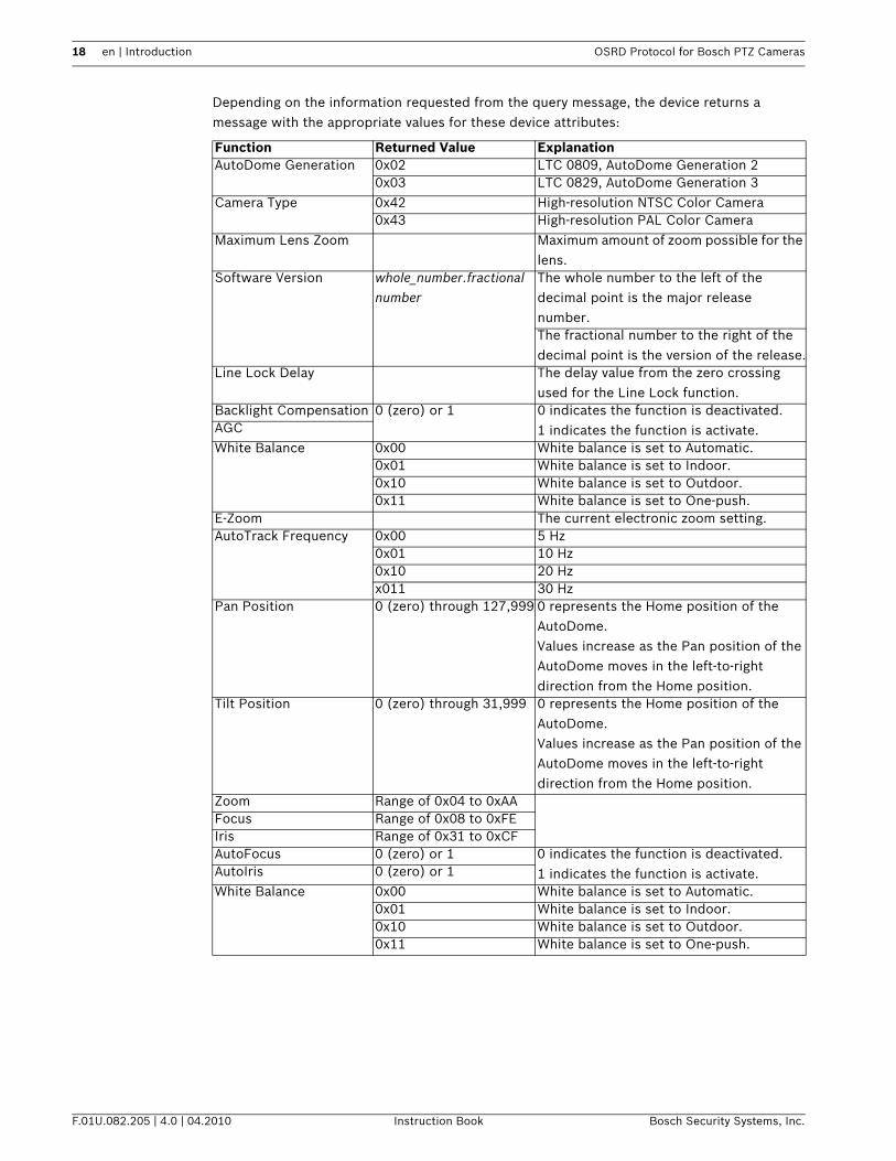
Depending on the information requested from the query message, the device returns a message with the appropriate values for these device attributes:
Function Returned Value ExplanationAutoDome Generation 0x02 LTC 0809, AutoDome Generation 2
0x03 LTC 0829, AutoDome Generation 3Camera Type 0x42 High-resolution NTSC Color Camera
0x43 High-resolution PAL Color CameraMaximum Lens Zoom Maximum amount of zoom possible for the
lens.Software Version whole_number.fractional
numberThe whole number to the left of the decimal point is the major release number.The fractional number to the right of the decimal point is the version of the release.
Line Lock Delay The delay value from the zero crossing used for the Line Lock function.
Backlight Compensation 0 (zero) or 1 0 indicates the function is deactivated.1 indicates the function is activate.AGC
White Balance 0x00 White balance is set to Automatic.0x01 White balance is set to Indoor.0x10 White balance is set to Outdoor.0x11 White balance is set to One-push.
E-Zoom The current electronic zoom setting.AutoTrack Frequency 0x00 5 Hz
0x01 10 Hz0x10 20 Hzx011 30 Hz
Pan Position 0 (zero) through 127,999 0 represents the Home position of the AutoDome. Values increase as the Pan position of the AutoDome moves in the left-to-right direction from the Home position.
Tilt Position 0 (zero) through 31,999 0 represents the Home position of the AutoDome.Values increase as the Pan position of the AutoDome moves in the left-to-right direction from the Home position.
Zoom Range of 0x04 to 0xAAFocus Range of 0x08 to 0xFEIris Range of 0x31 to 0xCFAutoFocus 0 (zero) or 1 0 indicates the function is deactivated.
1 indicates the function is activate.AutoIris 0 (zero) or 1White Balance 0x00 White balance is set to Automatic.
0x01 White balance is set to Indoor.0x10 White balance is set to Outdoor.0x11 White balance is set to One-push.

OSRD Protocol for Bosch PTZ Cameras Introduction | en 19
Bosch Security Systems, Inc. Instruction Book F.01U.082.205 | 4.0 | 04.2010
Command <0x87><Address MSB><Address LSB><0x0F><Data Requested Data Byte><AutoDome Data
Requested Data Byte><Tracking Components Data Byte><checksum>
Data Byte Codes7 6 5 4 3 2 1 0
Data
Requested
Data Byte
0 AutoTrack
Bit
AutoDome
Information
Request Bit
X X Special
Tracking
Mode Bit
AutoTrack
Frequency
Bit 1
AutoTrack
Frequency
Bit 2
Autodome
Data
Requested
Data Byte
0 Receiver/
Driver and
Camera
Type
Information
Bit
Receiver/
Driver
Software
Version Bit
Line Lock
Delay
Setting Bit
Camera
Settings
Data Bit
E-Zoom
Data Bit
X X
Tracking
Components
Requested
Data Byte
0 Query
Camera
Data Bit
Query Lens
Mode and
LSB Data
Bit
Query Iris
Position Bit
Query Focus
Position Bit
Query Zoom
Position Bit
Query Tilt
Position Bit
Query Pan
Position Bit
Reply 0 <length byte w/Bit7 set><Address MSB><Address LSB><0x4F>
<Data Requested Data Byte (with the Auto Track Bit set to 0)>
<Autodome Data Requested Data Byte><0x00><…Requested Data…><checksum>
Response Data Byte Codes7 6 5 4 3 2 1 0
Receiver/
Driver and
Camera Type
Information
0 AutoDome
Generation
Number Bit
6
AutoDome
Generation
Number Bit
5
AutoDome
Generation
Number Bit
4
AutoDome
Generation
Number Bit
3
AutoDome
Generation
Number Bit
2
AutoDome
Generation
Number Bit
1
AutoDome
Generation
Number Bit
0
0 Camera
Type Bit 6
Camera
Type Bit 5
Camera
Type Bit 4
Camera
Type Bit 3
Camera
Type Bit 2
Camera
Type Bit 1
Camera
Type Bit 0
0 Lens Max
Zoom Bit 6
Lens Max
Zoom Bit 5
Lens Max
Zoom Bit 4
Lens Max
Zoom Bit 3
Lens Max
Zoom Bit 2
Lens Max
Zoom Bit 1
Lens Max
Zoom Bit 0
Receiver/
Driver
Software
Version
0 Version
Whole
Number Bit
6
Version
Whole
Number Bit
5
Version
Whole
Number Bit
4
Version
Whole
Number Bit
3
Version
Whole
Number Bit
2
Version
Whole
Number Bit
1
Version
Whole
Number Bit
0
0 Version
Fractional
Number Bit
6
Version
Fractional
Number Bit
5
Version
Fractional
Number Bit
4
Version
Fractional
Number Bit
3
Version
Fractional
Number Bit
2
Version
Fractional
Number Bit
1
Version
Fractional
Number Bit
0
Line Lock
Delay Setting
0 Line Lock
Delay Bit 13
Line Lock
Delay Bit 12
Line Lock
Delay Bit 11
Line Lock
Delay Bit 10
Line Lock
Delay Bit 9
Line Lock
Delay Bit 8
Line Lock
Delay Bit 7
0 Line Lock
Delay Bit 6
Line Lock
Delay Bit 5
Line Lock
Delay Bit 4
Line Lock
Delay Bit 3
Line Lock
Delay Bit 2
Line Lock
Delay Bit 1
Line Lock
Delay Bit 0
Camera
Settings Data
0 X X X Backlight
Comp. Bit
AGC Bit White
Balance Bit
1
White
Balance Bit
0
E-Zoom Data 0 E-Zoom
Data Bit 6
E-Zoom
Data Bit 5
E-Zoom
Data Bit 4
E-Zoom
Data Bit 3
E-Zoom
Data Bit 2
E-Zoom
Data Bit 1
E-Zoom
Data Bit 0
Automatic
Position Reply
<length byte w/Bit7 set><Address MSB><Address LSB><0x4F><0x40><0x00>
<Tracking Components Data Byte><…Requested Data…><checksum>
Response Data Byte Codes7 6 5 4 3 2 1 0

20 en | Introduction OSRD Protocol for Bosch PTZ Cameras
F.01U.082.205 | 4.0 | 04.2010 Instruction Book Bosch Security Systems, Inc.
Pan Position
Data
0 0 0 0 0 Pan Position
Bit 16
Pan Position
Bit 15
Pan Position
Bit 14
0 Pan Position
Bit 13
Pan Position
Bit 12
Pan Position
Bit 11
Pan Position
Bit 10
Pan Position
Bit 9
Pan Position
Bit 8
Pan Position
Bit 7
0 Pan Position
Bit 6
Pan Position
Bit 5
Pan Position
Bit 4
Pan Position
Bit 3
Pan Position
Bit 2
Pan Position
Bit 1
Pan Position
Bit 0
Tilt Position
Data
0 0 0 0 0 0 0 Tilt Position
Bit 14
0 Tilt Position
Bit 13
Tilt Position
Bit 12
Tilt Position
Bit 11
Tilt Position
Bit 10
Tilt Position
Bit 9
Tilt Position
Bit 8
Tilt Position
Bit 7
0 Tilt Position
Bit 6
Tilt Position
Bit 5
Tilt Position
Bit 4
Tilt Position
Bit 3
Tilt Position
Bit 2
Tilt Position
Bit 1
Tilt Position
Bit 0
Lens Mode and
LSB Bit Data
0 X Auto Iris Bit Auto Focus
Bit
X Zoom
Position Bit
0
Focus
Position Bit
0
Iris Position
Bit 0
Zoom Position
Data
0 Zoom
Position Bit
7
Zoom
Position Bit
6
Zoom
Position Bit
5
Zoom
Position Bit
4
Zoom
Position Bit
3
Zoom
Position Bit
2
Zoom
Position Bit
1
Focus Position
Data
0 Focus
Position Bit
7
Focus
Position Bit
6
Focus
Position Bit
5
Focus
Position Bit
4
Focus
Position Bit
3
Focus
Position Bit
2
Focus
Position Bit
1
Iris Position
Data
0 Iris Position
Bit 7
Iris Position
Bit 6
Iris Position
Bit 5
Iris Position
Bit 4
Iris Position
Bit 3
Iris Position
Bit 2
Iris Position
Bit 1
Camera
Settings
0 X X X Backlight
Comp. Bit
AGC Bit White
Balance Bit
1
White
Balance Bit
0

OSRD Protocol for Bosch PTZ Cameras Introduction | en 21
Bosch Security Systems, Inc. Instruction Book F.01U.082.205 | 4.0 | 04.2010
3.2.7 Opcode 16 <0x10>: Title SetOpcode 16 <0x10> sends shot and zone titles to the camera device. Keep these conditions in mind when issuing this command:– The value of the Length byte is 0x85 + the number of characters in the title.– You must include leading spaces with a title. Trailing spaces, however, are not necessary.– The Opcode command overwrites previous titles.– The Opcode sends a maximum of 16 characters in the ASCII format.To specify the Title Number for the shot or the zone, use:– Shots 1 through 99: use the values 1 through 99, respectively.– Zones 1 through 16: use the values 100 through 116, respectively.The syntax for the Opcode 16 <0x10> command is:<0x8X><Address MSB><Address LSB><0x10><TitleNumber><Char1>…<Char16><checksum>
3.2.8 Opcode 18 <0x12>: Auxiliary Commands with DataOpcode 18 <0x12> directly adjusts and requests user-specified parameters, including parameters that accept actual values, not just On/Off commands. The following table lists the auxiliary commands and their associated values:
Auxiliary
Code
Command Name Pre-encoded Data Full Range Data
3 Iris Control 0 = Auto
1 = Manual
N/A
4 Focus Control 0 = Spot
1 = Continuous Auto
2 = Continuous Manual
9 Return On 0 = Off
1 = Preset 1
2 = Previous Aux
11 AutoIris Level Adjustment Step 1 to 15
14 AutoPan Speed 1 to 60 degrees/second
15 Pre-position Tour Period Index into a zero-based array
of seconds
(3, 4, 5, 10, 15, 20, 25, 30,
40, 50, 60, 120, 180, 240,
300, 600)
for example, 2 = 5 seconds
and 4 = 15 seconds
18 AutoPivot 0 = Off
1 = On
20 Backlight Compensation 0 = Off
1 = On

22 en | Introduction OSRD Protocol for Bosch PTZ Cameras
F.01U.082.205 | 4.0 | 04.2010 Instruction Book Bosch Security Systems, Inc.
23 Electronic Shutter X = NTSC - PAL
0 = Auto Slow Shutter
1 = 1
2 = 1/2
3 = 1/4 to 1/3
4 = 1/8 to 1/6
5 = 1/15 to 1/12
6 = 1/30 to 1/25
7 = 1/60 to 1/60
8 = 1/90 to 1/75
9 = 1/100 to 1/100
10 = 1/125 to 1/120
11 = 1/180 to 1/150
12 = 1/250 to 1/215
13 = 1/350 to 1/300
14 = 1/500 to 1/425
15 = 1/100 to 1/1000
16 = 1/1500 to 1/1250
17 = 1/2000 to 1/1750
18 = 1/3000 to 1/2500
19 = 1/4000 to 1/3500
20 = 1/6000 to 1/6000
21 = 1/10000 to 1/10000
24 Electronic Stabilization (25X
camera only)
0 = Off
1 = On
30 White Balance 0 = Auto
1 = Indoor
2 = Outdoor
3 = One Push
4 = Extended Auto
41 Line Lock Phase Adjust 0 to 359 degrees
42 Sync Mode 0 = Line Lock
1 = Crystal
43 AGC Maximum Gain Setting:
6 = 28 db
5 = 24 db
4 = 20 db
3 = 16 db
2 = 12 db
1 = 8 db
44 Aperture Correction Step 1 to 16
56 Night Mode 0 = Off
1 = On
2 = Auto
Auxiliary
Code
Command Name Pre-encoded Data Full Range Data

OSRD Protocol for Bosch PTZ Cameras Introduction | en 23
Bosch Security Systems, Inc. Instruction Book F.01U.082.205 | 4.0 | 04.2010
58 IRE Steps 1 through 10:
1 = 10 IRE
2 = 15 IRE
3 = 20 IRE
4 = 25 IRE
5 = 30 IRE
6 = 35 IRE
7 = 40 IRE
8 = 45 IRE
9 = 60 IRE
10 = 55 IRE
60 On-screen Display 0 = Off
1 = On
61 On-screen Display Adjust Data [7:0]: Line Number 0 to max
Data [15:8] = Brightness
65 Alarm/Relay State bit [3:0] (Get only):
Alarm input 3-1 state
1 = Active
2 = Not
bit [4] (Set/Get):
Relay Output
1 = Active
0 = Not
66 Display Software Version (Get only) Major.Minor
Data [15:8] = Major value
Data [7:0] = Minor value
80 Digital Zoom 0 = Disable
1 = Enable
86 Sector Masking Data [15:0] = sectors 1
through 16
91 Zoom Polarity 0 = Normal
1 = Reversed
92 Focus Polarity 0 = Normal
1 = Reversed
93 Iris Polarity 0 = Normal
1 = Reversed
201 PTZ Fixed-speed Control Speed Steps 1 through 15
202 Focus Speed Steps 1 through 8
203 Iris Speed Steps 1 through 10
204 Inactivity Period Index into a zero-based array
of seconds
(3, 4, 5, 10, 15, 20, 25, 30,
40, 50, 60, 120, 180, 240,
300, 600)
for example, 2 = 5 seconds
and 4 = 15 seconds
205 Max Zoom Speed 0 = Slowest
1 = Medium
2 = Fastest
Auxiliary
Code
Command Name Pre-encoded Data Full Range Data

24 en | Introduction OSRD Protocol for Bosch PTZ Cameras
F.01U.082.205 | 4.0 | 04.2010 Instruction Book Bosch Security Systems, Inc.
206 Unique Identifier Unique identifier that is burnt in
the program flash that is
currently used for
FastAddressing
207 Password Actual password in BCD format
208 Boot Code Revision (Get only) Major.Minor
Data [15:8] = Major value
Data [7:0] = Minor value
209 Alarm Setup Information Bit:
[1:0]: Alarm input -1
[3:2]: 00=Off, 01=N.O.,
10=N.C., 11=Pressure
[10:4]: Got to shot, 0=not
shot
[11] OSD: 1=yes, 0=no
[12] Transmit: 1=yes, 0=no
[13] Track: 1=yes, 0=no
Auxiliary
Code
Command Name Pre-encoded Data Full Range Data

OSRD Protocol for Bosch PTZ Cameras Introduction | en 25
Bosch Security Systems, Inc. Instruction Book F.01U.082.205 | 4.0 | 04.2010
3.2.9 Opcode 19 <0x13>: Set PositionOpcode 19 <0x13> Set sends pan, tilt, and zoom positions (expressed in radians x 1000) and sends the focal length (expressed in mm x 10) to a PTZ device. For example, if the operator needs to set the pan position to 1.234 radians, the command sends the value as 1234 (as a hexadecimal value); and if the operator needs to set the focal length to 5.6 mm, the command sends the value as 56 (as a hexadecimal value).
Setting the Camera PositionTo set the camera pan or tilt position you must convert the original value (typically expressed in degrees) several times to arrive at a hexadecimal value for the high-order data value byte (data byte 1) and for the low-order data value byte (data byte 2). Use the following order of conversions:– Convert degrees to radians using the following equation:
Radians = Degrees x (π/180)
– Multiply radians by 1000.– Convert the decimal radian value into a binary number.– Split the binary number into the high-order and the low-order byte values.– Convert the high-order and the low-order byte values into hexadecimal values.
Function Set PositionCommand <0x8B><Address MSB><Address LSB><0x13><Ignore Data><Pan Position Data Byte 1>
<Pan Position Data Byte 2><Tilt Position Data Byte 1><Tilt Position Data Byte 2>
<Focal Length Data Byte 1><Focal Length Data Byte 2><checksum>
Data Byte Codes7 6 5 4 3 2 1 0
Ignore
Data
0 0 0 0 0 Ignore Zoom Ignore Tilt Ignore Pan
Pan
Position
Data 1
0 Ignore Pan
Position
Pan Position
Bit 12
Pan Position
Bit 11
Pan Position
Bit 10
Pan Position
Bit 9
Pan Position
Bit 8
Pan Position
Bit 7
Pan
Position
Data 2
0 Pan Position
Bit 6
Pan Position
Bit 5
Pan Position
Bit 4
Pan Position
Bit 3
Pan Position
Bit 2
Pan Position
Bit 1
Pan Position
Bit 0
Tilt
Position
Data 1
0 Ignore Tilt
Position
Tilt Position
Bit 12
Tilt Position
Bit 11
Tilt Position
Bit 10
Tilt Position
Bit 9
Tilt Position
Bit 8
Tilt Position
Bit 7
Tilt
Position
Data 2
0 Tilt Position
Bit 6
Tilt Position
Bit 5
Tilt Position
Bit 4
Tilt Position
Bit 3
Tilt Position
Bit 2
Tilt Position
Bit 1
Tilt Position
Bit 0
Focal
Length
Data 1
0 Focal Length
Bit 13
Focal Length
Bit 12
Focal Length
Bit 11
Focal Length
Bit 10
Focal Length
Bit 9
Focal Length
Bit 8
Focal Length
Bit 7
Focal
Length
Data 2
0 Focal Length
Bit 6
Focal Length
Bit 5
Focal Length
Bit 4
Focal Length
Bit 3
Focal Length
Bit 2
Focal Length
Bit 1
Focal Length
Bit 0
Reply No Reply
26 en | Introduction OSRD Protocol for Bosch PTZ Cameras
F.01U.082.205 | 4.0 | 04.2010 Instruction Book Bosch Security Systems, Inc.
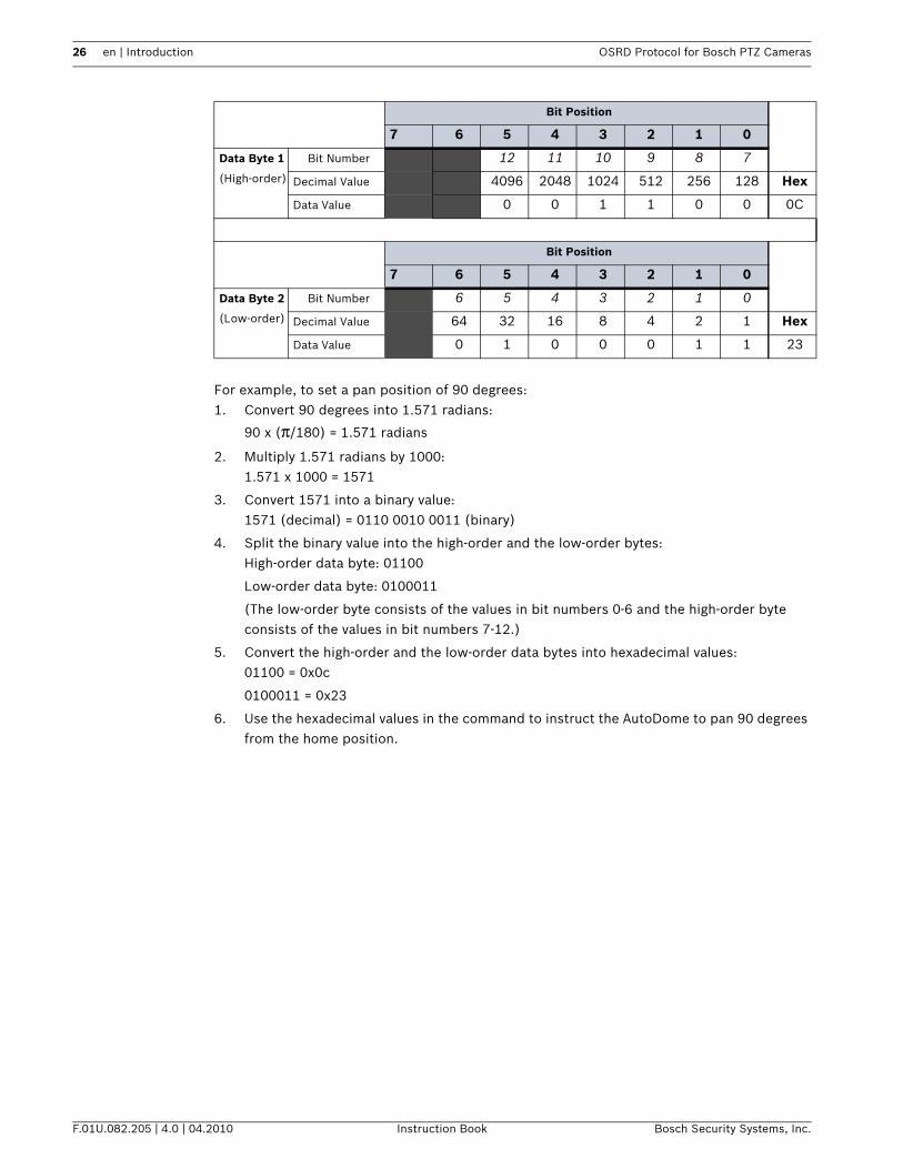
For example, to set a pan position of 90 degrees:1. Convert 90 degrees into 1.571 radians:
90 x (π/180) = 1.571 radians
2. Multiply 1.571 radians by 1000:1.571 x 1000 = 1571
3. Convert 1571 into a binary value:1571 (decimal) = 0110 0010 0011 (binary)
4. Split the binary value into the high-order and the low-order bytes: High-order data byte: 01100
Low-order data byte: 0100011
(The low-order byte consists of the values in bit numbers 0-6 and the high-order byte consists of the values in bit numbers 7-12.)
5. Convert the high-order and the low-order data bytes into hexadecimal values:01100 = 0x0c
0100011 = 0x23
6. Use the hexadecimal values in the command to instruct the AutoDome to pan 90 degrees from the home position.
Bit Position
7 6 5 4 3 2 1 0
Data Byte 1
(High-order)
Bit Number 12 11 10 9 8 7
Decimal Value 4096 2048 1024 512 256 128 Hex
Data Value 0 0 1 1 0 0 0C
Bit Position
7 6 5 4 3 2 1 0
Data Byte 2
(Low-order)
Bit Number 6 5 4 3 2 1 0
Decimal Value 64 32 16 8 4 2 1 Hex
Data Value 0 1 0 0 0 1 1 23
OSRD Protocol for Bosch PTZ Cameras Introduction | en 27
Bosch Security Systems, Inc. Instruction Book F.01U.082.205 | 4.0 | 04.2010
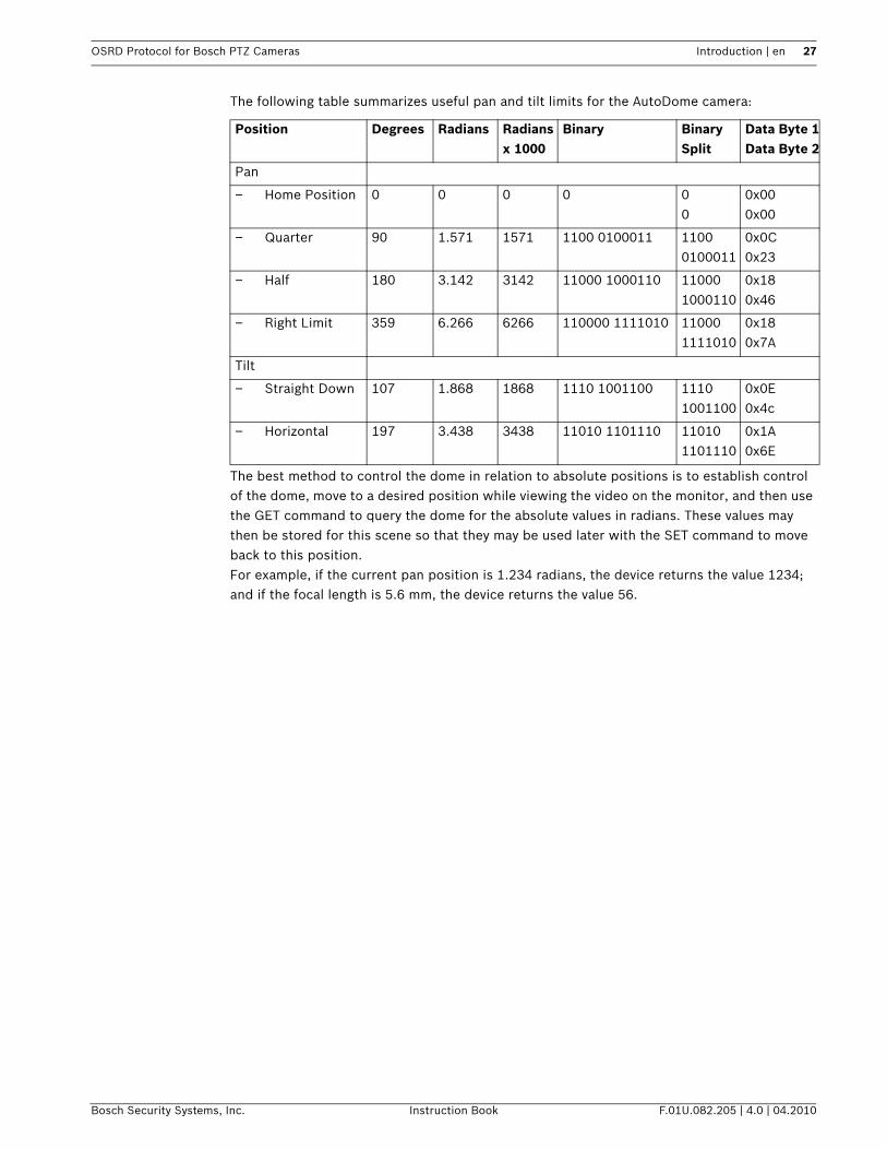
The following table summarizes useful pan and tilt limits for the AutoDome camera:
The best method to control the dome in relation to absolute positions is to establish control of the dome, move to a desired position while viewing the video on the monitor, and then use the GET command to query the dome for the absolute values in radians. These values may then be stored for this scene so that they may be used later with the SET command to move back to this position.For example, if the current pan position is 1.234 radians, the device returns the value 1234; and if the focal length is 5.6 mm, the device returns the value 56.
Position Degrees Radians Radians x 1000
Binary Binary Split
Data Byte 1Data Byte 2
Pan
– Home Position 0 0 0 0 00
0x000x00
– Quarter 90 1.571 1571 1100 0100011 11000100011
0x0C0x23
– Half 180 3.142 3142 11000 1000110 110001000110
0x180x46
– Right Limit 359 6.266 6266 110000 1111010 110001111010
0x180x7A
Tilt
– Straight Down 107 1.868 1868 1110 1001100 11101001100
0x0E0x4c
– Horizontal 197 3.438 3438 11010 1101110 110101101110
0x1A0x6E

28 en | Introduction OSRD Protocol for Bosch PTZ Cameras
F.01U.082.205 | 4.0 | 04.2010 Instruction Book Bosch Security Systems, Inc.
3.2.10 Opcode 19 <0x13>: Get PositionOpcode 19 <0x13> Get queries the device for its current pan, tilt, and zoom positions (expressed in radians x 1000) and its current focal length (expressed in mm x 10). For example, if the current pan position is 1.234 radians, the device returns the value 1234; and if the focal length is 5.6 mm, the device returns the value 56.This command returns a different reply length depending on the version of the AutoDome.
Function Get Position Command <0x84><Address MSB><Address LSB><0x13<checksum>
Data Byte Codes: NoneReply
(VG4, 11
bytes)
<0x8A><Address MSB><Address LSB><0x53><Pan Position Data Byte 1>
<Pan Position Data Byte 2><Tilt Position Data Byte 1><Tilt Position Data Byte 2>
<Focal Length Data Byte 1><Focal Length Data Byte 2><checksum>
Reply
(G3, 12
bytes)
<0x8B>><Address MSB><Address LSB><0x53><Ignore Data><Pan Position Data Byte 1><Pan
Position Data Byte 2><Tilt Position Data Byte 1><Tilt Position Data Byte 2><Focal Length Data
Byte 1><Focal Length Data Byte 2><checksum>

OSRD Protocol for Bosch PTZ Cameras Introduction | en 29
Bosch Security Systems, Inc. Instruction Book F.01U.082.205 | 4.0 | 04.2010
4 Opcode 20 <0x14>: BiCom Command InterfaceThis chapter describes the syntax and structure of a BiCom command sent within an OSRD message packet using Opcode 20 <0x14>. This Opcode allows a controller device to send a BiCom command to a camera that supports only the Standard Opcodes.This chapter describes the three aspects of the BiCom protocol:– The syntax for sending a BiCom command within an OSRD message packet.– The method to identify the command that sends an instruction to or receives a value from
a VG4 Series AutoDome.– The location of each bit in the command message.
See the BiCom Protocol for Bosch PTZ Cameras manual for a full description of the BiCom protocol.
iNOTICE! You must use a BiCom command within an OSRD message packet (using Opcode 20 <0x14> to send or an Extended Opcode command to a VG4 Series AutoDome.

30 en | Introduction OSRD Protocol for Bosch PTZ Cameras
F.01U.082.205 | 4.0 | 04.2010 Instruction Book Bosch Security Systems, Inc.
4.1 Data Byte CodesEach component of the command syntax after the <0x14> constant consists of a value in each bit location for a byte or a two-byte number.
Data Bit Position7 6 5 4 3 2 1 0
Length value = 1 Bit 6 Bit 5 Bit 4 Bit 3 Bit 2 Bit 1 Bit 0
Address MSB value = 0 Bit 14 Bit 13 Bit 12 Bit 11 Bit 10 Bit 9 Bit 8
LSB value = 0 Bit 6 Bit 5 Bit 4 Bit 3 Bit 2 Bit 1 Bit 0
Server ID MSB Bit 15 Bit 14 Bit 13 Bit 12 Bit 11 Bit 10 Bit 9 Bit 8
LSB Bit 7 Bit 6 Bit 5 Bit 4 Bit 3 Bit 2 Bit 1 Bit 0
Opocode 14 value = 0 value = 0 value = 0 value = 1 value = 0 value = 1 value = 0 value = 0
Object/
Member ID
MSB Object Bit 12 Object Bit 11 Object Bit 10 Object Bit 9 Object Bit 8 Object Bit 7 Object Bit 6 Object Bit 5
LSB Object Bit 4 Object Bit 3 Object Bit 2 Object Bit 1 Member Bit 3 Member Bit 2 Member Bit 1 Member Bit 0
Operation Bit 7 Bit 6 Bit 5 Bit 4 Bit 3 Bit 2 Bit 1 Bit 0
Data Byte 1 Bit 7 Bit 6 Bit 5 Bit 4 Bit 3 Bit 2 Bit 1 Bit 0
Data Byte N
(15 max)
Bit 7 Bit 6 Bit 5 Bit 4 Bit 3 Bit 2 Bit 1 Bit 0
Checksum value=0 Bit 6 Bit 5 Bit 4 Bit 3 Bit 2 Bit 1 Bit 0

OSRD Protocol for Bosch PTZ Cameras Introduction | en 31
Bosch Security Systems, Inc. Instruction Book F.01U.082.205 | 4.0 | 04.2010
4.2 BiCom Byte Descriptions The following sections describe the bytes required by the BiCom protocol to send a command. See the BiCom Protocol for Bosch PTZ Cameras manual for a full description of the BiCom protocol.
4.2.1 Server IDThe Server ID parameter consists of two bytes. Once the eight positions of the LSB are filled, use the next 8 positions in the MSB.
4.2.2 Object/Member IDThe Object/Member ID bytes consist of two bytes, but the division of the MSB and the LSB differ from that of the Server ID. Using the object/member pair allows you to group settings in one object. For example, the object Position contains the members Orientation and Area (among others). The Member ID consists of the first four bit positions of the LSB (0, 1, 2, 3) and the Object ID consists of bit position 4 through 7 of the LSB and all eight bit positions of the MSB. For example, the following two-byte string contains the ID for the Position object and the ID for the Orientation member:
This two-byte string translates to 0x011A in hexidecimal.
4.2.3 OperationIdentifies the Operation to be preformed on the object/member. The Generic Operations Type table, below, describes the operations in the range 0x00–0x7F that are common to all object/members (not all operations are available on all object/members). See the BiCom Protocol for Bosch PTZ Cameras manual for a full description of the Generic operations. Every object can also define its own unique operations, which reside in the range 0x80–0xFF.
Server Name Server ID MSB Server ID LSBDevice Server 0x00 0x020I/O Server 0x00 0x0A0Content Analysis (CA) Server 0x00 0x080Camera Server 0x00 0x040PTZ Server 0x00 0x060
Object ID Member IDMSB LSB0 0 0 0 0 0 0 1 0 0 0 1 1 0 1 0Position Object Orientation Member
Operation Code DescriptionGet 0x01 Returns the object value.Set 0x02 Sets the object value.SetGet 0x03 Sets the object value and returns it.Inc 0x04 Increments the object value with a predefined value.IncGet 0x05 Increments the object value with a predefined value and returns it.Dec 0x06 Decrements the object value with a predefined value.DecGet 0x07 Decrements the object value with a predefined value and returns
it.SetDefault 0x08 Resets the object value to the default value.SetGetDefault 0x09 Resets the object value to the default value and returns the new
value.Nop 0x0A No function. The operation is used to check if an object exists.GetMax 0x0B Returns the maximum value of the object.GetMin 0x0C Returns the minimum value of the object.Reserved 0x0D–0x06EError 0x6F ErrorEvent 0x70–0x7F Returns a value on an event (not requested).

32 en | Introduction OSRD Protocol for Bosch PTZ Cameras
F.01U.082.205 | 4.0 | 04.2010 Instruction Book Bosch Security Systems, Inc.
4.2.4 Data BytesEach BiCom requires a specific number of data byte fields. See the BiCom Protocol for Bosch PTZ Cameras manual for a full description of the data bytes required for each BiCom
command.
OSRD Protocol for Bosch PTZ Cameras Introduction | en 33
Bosch Security Systems, Inc. Instruction Book F.01U.082.205 | 4.0 | 04.2010
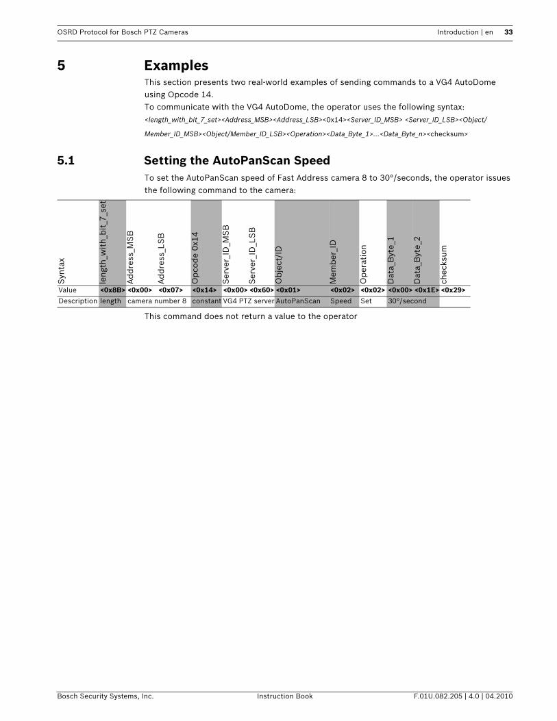
5 ExamplesThis section presents two real-world examples of sending commands to a VG4 AutoDome using Opcode 14. To communicate with the VG4 AutoDome, the operator uses the following syntax:<length_with_bit_7_set><Address_MSB><Address_LSB><0x14><Server_ID_MSB> <Server_ID_LSB><Object/
Member_ID_MSB><Object/Member_ID_LSB><Operation><Data_Byte_1>…<Data_Byte_n><checksum>
5.1 Setting the AutoPanScan SpeedTo set the AutoPanScan speed of Fast Address camera 8 to 30°/seconds, the operator issues the following command to the camera:
This command does not return a value to the operator
Syn
tax
leng
th_w
ith_
bit
_7_s
et
Ad
dre
ss_M
SB
Ad
dre
ss_L
SB
Op
cod
e 0x
14
Ser
ver_
ID_M
SB
Ser
ver_
ID_L
SB
Ob
ject
/ID
Mem
ber
_ID
Op
erat
ion
Dat
a_B
yte_
1
Dat
a_B
yte_
2
chec
ksum
Value <0x8B> <0x00> <0x07> <0x14> <0x00> <0x60> <0x01> <0x02> <0x02> <0x00> <0x1E> <0x29>Description length camera number 8 constant VG4 PTZ server AutoPanScan Speed Set 30°/second
34 en | Introduction OSRD Protocol for Bosch PTZ Cameras
F.01U.082.205 | 4.0 | 04.2010 Instruction Book Bosch Security Systems, Inc.
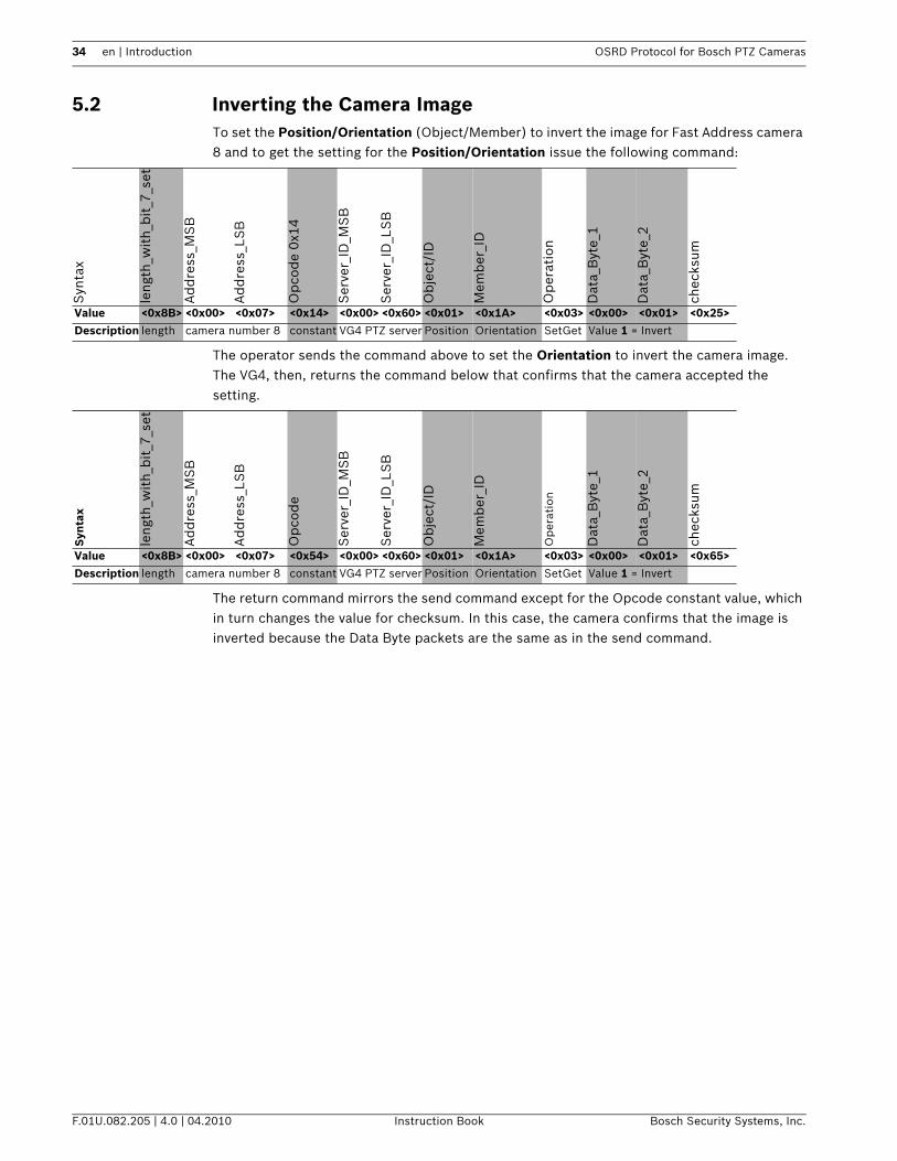
5.2 Inverting the Camera ImageTo set the Position/Orientation (Object/Member) to invert the image for Fast Address camera 8 and to get the setting for the Position/Orientation issue the following command:
The operator sends the command above to set the Orientation to invert the camera image. The VG4, then, returns the command below that confirms that the camera accepted the setting.
The return command mirrors the send command except for the Opcode constant value, which in turn changes the value for checksum. In this case, the camera confirms that the image is inverted because the Data Byte packets are the same as in the send command.
Syn
tax
leng
th_w
ith_
bit
_7_s
et
Ad
dre
ss_M
SB
Ad
dre
ss_L
SB
Op
cod
e 0x
14
Ser
ver_
ID_M
SB
Ser
ver_
ID_L
SB
Ob
ject
/ID
Mem
ber
_ID
Op
erat
ion
Dat
a_B
yte_
1
Dat
a_B
yte_
2
chec
ksum
Value <0x8B> <0x00> <0x07> <0x14> <0x00> <0x60> <0x01> <0x1A> <0x03> <0x00> <0x01> <0x25>Description length camera number 8 constant VG4 PTZ server Position Orientation SetGet Value 1 = Invert
Syn
tax
leng
th_w
ith_
bit
_7_s
et
Ad
dre
ss_M
SB
Ad
dre
ss_L
SB
Op
cod
e
Ser
ver_
ID_M
SB
Ser
ver_
ID_L
SB
Ob
ject
/ID
Mem
ber
_ID
Op
erat
ion
Dat
a_B
yte_
1
Dat
a_B
yte_
2
chec
ksum
Value <0x8B> <0x00> <0x07> <0x54> <0x00> <0x60> <0x01> <0x1A> <0x03> <0x00> <0x01> <0x65>Description length camera number 8 constant VG4 PTZ server Position Orientation SetGet Value 1 = Invert
OSRD Protocol for Bosch PTZ Cameras Introduction | en 35
Bosch Security Systems, Inc. Instruction Book F.01U.082.205 | 4.0 | 04.2010
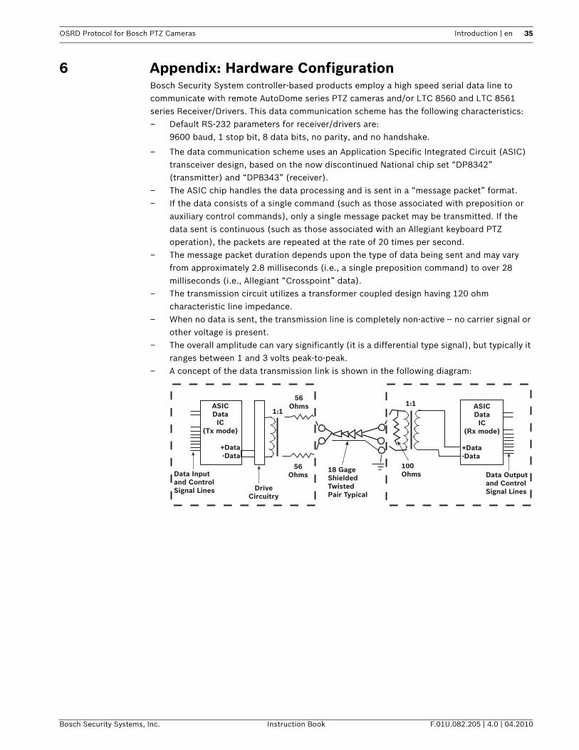
6 Appendix: Hardware ConfigurationBosch Security System controller-based products employ a high speed serial data line to communicate with remote AutoDome series PTZ cameras and/or LTC 8560 and LTC 8561 series Receiver/Drivers. This data communication scheme has the following characteristics:– Default RS-232 parameters for receiver/drivers are:
9600 baud, 1 stop bit, 8 data bits, no parity, and no handshake.
– The data communication scheme uses an Application Specific Integrated Circuit (ASIC) transceiver design, based on the now discontinued National chip set “DP8342” (transmitter) and “DP8343” (receiver).
– The ASIC chip handles the data processing and is sent in a “message packet” format.– If the data consists of a single command (such as those associated with preposition or
auxiliary control commands), only a single message packet may be transmitted. If the data sent is continuous (such as those associated with an Allegiant keyboard PTZ operation), the packets are repeated at the rate of 20 times per second.
– The message packet duration depends upon the type of data being sent and may vary from approximately 2.8 milliseconds (i.e., a single preposition command) to over 28 milliseconds (i.e., Allegiant “Crosspoint” data).
– The transmission circuit utilizes a transformer coupled design having 120 ohm characteristic line impedance.
– When no data is sent, the transmission line is completely non-active -- no carrier signal or other voltage is present.
– The overall amplitude can vary significantly (it is a differential type signal), but typically it ranges between 1 and 3 volts peak-to-peak.
– A concept of the data transmission link is shown in the following diagram:
Data Inputand ControlSignal Lines Drive
Circuitry
56Ohms
56Ohms
1:11:1ASIC
DataIC
(Tx mode)
+Data-Data
18 GageShieldedTwistedPair Typical
100Ohms
ASICData
IC(Rx mode)
+Data-Data
Data Outputand ControlSignal Lines
36 en | Introduction OSRD Protocol for Bosch PTZ Cameras
F.01U.082.205 | 4.0 | 04.2010 Instruction Book Bosch Security Systems, Inc.
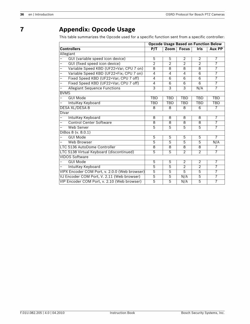
7 Appendix: Opcode UsageThis table summarizes the Opcode used for a specific function sent from a specific controller:
Opcode Usage Based on Function BelowControllers P/T Zoom Focus Iris Aux PPAllegiant– GUI (variable speed icon device) 5 5 2 2 7– GUI (fixed speed icon device) 2 2 2 2 7– Variable Speed KBD (UF22=Var; CPU 7 on) 8 8 8 8 7– Variable Speed KBD (UF22=Fix; CPU 7 on) 4 4 4 6 7– Fixed Speed KBD (UF22=Var; CPU 7 off) 4 6 6 6 7– Fixed Speed KBD (UF22=Var; CPU 7 off) 4 6 6 6 7– Allegiant Sequence Functions 3 3 3 N/A 7BVMS– GUI Mode TBD TBD TBD TBD TBD– IntuiKey Keyboard TBD TBD TBD TBD TBDDESA XL/DESA 8 8 8 8 6 7Divar– IntuiKey Keyboard 8 8 8 8 7– Control Center Software 8 8 8 8 7– Web Server 5 5 5 5 7DiBos 8 (v. 8.0.1)– GUI Mode 5 5 5 5 7– Web Browser 5 5 5 5 N/ALTC 5136 AutoDome Controller 8 8 8 8 7LTC 5138 Virtual Keyboard (discontinued) 5 5 2 2 7VIDOS Software– GUI Mode 5 5 2 2 7– IntuiKey Keyboard 5 5 2 2 7VIPX Encoder COM Port, v. 2.0.0 (Web browser) 5 5 5 5 7VJ Encoder COM Port, V. 2.11 (Web browser) 5 5 N/A 5 7VIP Encoder COM Port, v. 2.10 (Web browser) 5 5 N/A 5 7


AmericasBosch Security Systems, Inc. 850 Greenfield RoadLancaster, Pennsylvania 17601USATelephone +1 888-289-0096Fax +1 585-223-9180Email: [email protected]
Europe, Middle East, Africa:Bosch Security Systems B.V.P.O. Box 800025600 JB Eindhoven, The NetherlandsPhone: + 31 40 2577 284Fax: +31 40 2577 [email protected]
Asia-Pacific:Bosch Security Systems Pte Ltd38C Jalan PemimpinSingapore 577180Phone: +65 6319 3450Fax: +65 6319 [email protected]
© Bosch Security Systems, Inc. 2008; F.01U.082.205 | 4.0 | 04.2010; Data subject to change without notice.