Oscillating Displacement Pumps Performance and...
71
Copyright FELUWA Pumpen GmbH 5th OMB conference Nanjing Presentation - Shicheng Hall - on November 7, 2016 Heinz M. Nägel Oscillating Displacement Pumps Performance and Characteristics of Positive Displacement Pumps
Transcript of Oscillating Displacement Pumps Performance and...

Copyright FELUWA Pumpen GmbH
5th OMB conference Nanjing Presentation - Shicheng Hall - on November 7, 2016
Heinz M. Nägel
Oscillating Displacement Pumps Performance and Characteristics of Positive Displacement Pumps

Copyright FELUWA Pumpen GmbH 2 Heinz M. Nägel 2016
Contents: •Pump Characteristic •Pump Heads •Ideal Principle •Application Ranges •Head – Conveying Properties •Influence of the Medium •Comparison between Piston and Diaphragm pump •Self-acting Valves – Typical design •Pulsation Dampeners •NPSH
Foliennr.
Oscillating Displacement Pumps Performance and Characteristics

Low loss due leakage and compressibility
Pressure stiff is a precondition for dosing processes
p = f (V)
∆p
∆V V .
Pressure stiff means: p,H 1
2
p
Plant curve
3
Pump Characteristic Curves Characteristic conveying curves .
Heinz M. Nägel 2016

Up to 20.000 bar < 800 bar < 350 bar
< 16 bar < 5 bar < 5 bar
< 150 °C < 130 °C < 500 °C
< 80 °C < 80 °C < 100°C 4
Oscillating Displacement Pumps Pump Heads
< 400 bar
< 200 °C
< 200 bar
< 200 °C Heinz M. Nägel 2016

5
Oscillating Displacement Pumps (Piston Pump including suction and discharge air vessel)
Heinz M. Nägel 2016

D
FLUID
R
ϕ
Schritt 1
V L
VS
p = vacuum up to 20 000 bar
Flow: 5 ml/h up to 300 m3/h
Viscosity up to 1500 Pas
T = -270 up to 500°C
Fluids: toxic, abrasive, aggressive, corrosive, supensions Hermetic design: diaphragm pump
Vth = Vh ⋅ n
V = Vth ⋅ηV
6
Oscillating Displacement Pumps Application Ranges
•
•
•
•

Fluid compressibility:
Vk
χ = ∆V ⋅ 1 = 1 V ∆p E
The dead space reduces the real stroke volume. The loss gets visible vie the duration of the expansion process.
V VL
Dead space ration: ε = DS
The bigger the compressibility, the smaller the dead space should be.
Oscillating Displacement Pumps Pump Volumetric Efficiency/Dead space
ps: Suction pressure
7
Heinz M. Nägel 2016
Dead space

Steel: Water:
E = 210 000 N/mm2
E = σ/ε
z.B. p = 100 bar = 10 N/mm2
ε=0,5%/100 bar E = 2000 N/mm2
The elasticity of the parts λAR often can be
ignored
p
ηV ≈ 1− (εTκ + λAR ) Δp
k AR V ∆p E
= ∆VE ⋅ 1 = 1 λ
Oscillating Displacement Pumps Pump Volumetric Efficiency Elasticity of the parts / liquid
8
Heinz M. Nägel 2016

Kinematics effect on suction and discharge piping system
Oscillating Displacement Pumps
Heinz M. Nägel 2016

λs = 0
λs = 0,075 λs = 0,150 λs = 0,225
0° 180° ϕ 360°
v k (ϕ
) v k
har
m
rel.
Ver
drän
gerg
esch
win
digk
eit
180°
0°
ϕ 360°
1,0
b k (ϕ
) b k
har
m
rel.
Ver
drän
gerg
esch
win
digk
eit
λs = 0 λs = 0,075 λs = 0,150 λs = 0,225
Druckhub Saughub
000729 0010
λ = r / L D
FLUID
R
ϕ
Schritt 1
V L
VS
Oscillating Displacement Pumps Stroke Kinematics Influence of the shaft-radius-ratio
10
Heinz M. Nägel 2016

2π
π 3π Krankshaft angle
Pis
tons
peed
vk
ηv3< ηv2< ηv1< ηv,th.
Discharge Suction stroke
ηv3
ηv2
ηv1
∆v
What happens with the valves?
ΔpJ = ρ⋅c⋅ Δv
Oscillating Displacement Pumps Conveying Kinematics Phase Cut – Pressure shock - Joukowsky Shock
11

• Valve leakage • Compression • Expansion • Suction Avoid all!
Consequences from the possibilities for failures
Due a long and precise stroke
Oscillating Displacement Pumps Conveying Properties – Ideal Principle
12

13
Pump flow rate
Ope
ratin
g pr
essu
re [
bar]
Oscillating Displacement Pumps Flow characteristic (Simplex pump)
Heinz M. Nägel 2016

Oscillating Displacement Pumps Flow characteristic (Duplex pump)
14
Pump flow rate
Ope
ratin
g pr
essu
re [
bar]
Heinz M. Nägel 2016

Oscillating Displacement Pumps Flow characteristic Triplex pump
15
Pump flow rate
Ope
ratin
g pr
essu
re [
bar]
Heinz M. Nägel 2016

Oscillating Displacement Pumps Flow characteristic Quadruplex pump
16
Pump flow rate
Ope
ratin
g pr
essu
re [
bar]
Heinz M. Nägel 2016

Oscillating Displacement Pumps Flow characteristic (Quintuplex pump)
17
Pump flow rate
Ope
ratin
g pr
essu
re [
bar]
Heinz M. Nägel 2016

Pulsation dampening
Oscillating Displacement Pumps
Heinz M. Nägel 2016

Ideal Acting Principle
H / S
Pulsation!
t
19
Oscillating Displacement Pumps Head Properties
Heinz M. Nägel 2016

Pulsation Dampeners
20
Air vessel Air vessel Bladder Traditional bladder
Hose-diaphragm pulsation dampener
Reciprocating pump system
Pulsorber
Heinz M. Nägel 2016 Heinz M. Nägel 2016

Copyright FELUWA Pumpen GmbH 21
Pulsation Dampener - Adjustable Air Vessel System -
Dr. Stefan Willems
Pressure
Air cushion
Medium
Inlet Outlet Pressure
Prefilling before pump is started: 80% of working pressure
During operation: Pressure in air vessel is equal to working pressure
No. E 2201139-1

Copyright FELUWA Pumpen GmbH Heinz M. Nägel
Pulsation dampeners are used for reducing pressure and flow rate fluctuations, as well as smoothing of resultant pressure surges. Only the conveyed medium between pulsation dampener and piston must be accelerated and decelerated, whilst the flow velocity inside the pipelines remains almost constant. The air vessel’s effect depends on the air volume that serves as a cushion for the arising pressure peaks. To keep the medium mass accelerated by the pump stroke as low as is practicable, the pulsation dampeners must be installed as close as possible to the pumps.
Oscillating Displacement Pumps Pulsation Dampener

Copyright FELUWA Pumpen GmbH
• p bar Operating pressure • Δp bar Pressure fluctuation • VK Liter Displaced volume • VG Liter Active dampening volume • δ - Degree of kinematic irregularity • κ - Isentropic exponent
23
Residual Pulsation

Valves – Characteristics and applications
Oscillating Displacement Pumps
Heinz M. Nägel 2016

Valve types •Ball valve •Plate valve •Cone valve
Feder
FStrömung
FStrömung
FF FF Ventilkörper
FG
FT FT
Always pressure balanced
Oscillating Displacement Pumps (Self-acting Valves – Typical Check valves design)
25 Heinz M. Nägel 2016

t
p
H
UT ∆t
tHE
ts
p
OT H
OT UT
H
000825 0103
p
Wear and closing delay should be minimal
Oscillating Displacement Pumps Valves Second best design – classical piston pump
But! With optimal valves •Matching the fluid properties •Optimum geometry
26

Goal: Optimal thight valves with long duration Problem: Opening and closing process
tS
VR
Correctives
Manufacturing quality/precision
Spherical balls
Sharp seal geometries
and ....safety...
Double ball valves
Triple valve configuration More safety
Special material balls
Closing delay!
Guiding quality
Sphericity of the ball
Adhesive effects
Oscillating Displacement Pumps (Self-acting Valves)
27

Copyright FELUWA Pumpen GmbH 28
Special Configurations - Double Valves -
Double Valves
• Double valves are used for critical processes which do not allow interrupted flow.
• Double valves provide double safety against smallest leakages.
• Double valves reduce valve wear and increase maintenance intervals.
Heinz M. Nägel No. E 2201058

Copyright FELUWA Pumpen GmbH 29
- Flow loss of single valves -
Heinz M. Nägel Foliennr. E 2201172
The valve opens after the air that is enclosed in the product, has been compressed to a pressure that exceeds the working pressure. The resulting loss of pressure is compensated during the opening cycle. This results in an overspeed that depends on the coefficient of the loss of pressure of the valve.
Oscillating Displacement Pumps Wear of ball valves

Copyright FELUWA Pumpen GmbH 30
Wear of ball valves - Flow loss in double valves -
Heinz M. Nägel Foliennr. E 2201173
With double valve configuration the valve that is the closest to the pump opens first. Due to the low dead space within the valve, little flow is sufficient to increase the pressure to an extent that the second valve opens. As a result of double pressure loss the overspeed is reduced accordingly. Double valve configuration, as illustrated, allows for considerably extended life cycles.

Copyright FELUWA Pumpen GmbH 31
Ball Valve vs. Cone Valve
No. E 2109241-3 Heinz M. Nägel
Ball Valve
Valve seat (reversible)
Ball guide
Valve ball
Ball Valve
Valve seat (reversible)Valve seat (reversible)
Ball guideBall guide
Valve ballValve ball
Cone ValveGuide bush
Compression spring
Rubber ring
Valve seatCone guide
Cone top guide
Cone valve disc
Cone ValveGuide bushGuide bush
Compression springCompression spring
Rubber ringRubber ring
Valve seatValve seatCone guideCone guide
Cone top guideCone top guide
Cone valve discCone valve disc

103 105 2 2 4 6 8
104 2 8
1,00
0,99 0,98 0,97
0,96
0,95
1,6 bar 0,1 bar
4 6 8
Federbelastung FF
mPas η
η G
102
y 100
E E,OVP
y −B ⋅p η = η = 1− A
h ⋅ 100 + R
G η n V
Δp n V η = 1 − C
tS
VR
AR
V T η ≈ 1− (ε κ + λ ) Δp
ηG often very little!
But wear changes !!!
Spring Load
All elasticities: fluid, oil, parts!
All losses: Leakages!
Oscillating Displacement Pumps Volumetric Efficiency Elasticity factor, quality factor
32

Copyright FELUWA Pumpen GmbH 33 Heinz M. Nägel Foliennr. E 2201172
Oscillating Displacement Pumps Wear of valves
Valve seat Worn out Valve Seat Removed
from a high-pressure slurry pump

Copyright FELUWA Pumpen GmbH 34
Energy Balance in Case of Leaking Check Valves - Energy Loss in Case of Leaking Check Valves -
Leakage in discharge and/or suction valve
Suction stroke

Copyright FELUWA Pumpen GmbH 35 Heinz M. Nägel E 2201186-1
Oscillating Displacement Pumps Energetic and volumetric efficiencies
1. In the case of high viscosities, particularly when the fluid is carrying particles, the following applies: The deformation/deflection of the natural flow lines should be kept as little as possible. Deflections, such as result from angle valves, affect the suction and cause the shearing effect.
2. The more gentle the product passes through the valves, the lower the wear rate.
3. Influence of pressure Special influencing value – Differential pressure in the sealing area. Examples: Abrasive particles in suspension can create a valve gap / leak. The prevailing pressure at the gap generates high flow velocity = liquid peaks + flow cavitation = wear. Particles enhance the effect! Risk of cavitation!
4. Considerable variations of product density: Sedimentation or floating. Fluids that tend to sedimentation can hardly be sucked in.
Remedy: Downflow Technology

Copyright FELUWA Pumpen GmbH 36 Copyright FELUWA Pumpen GmbH – Heinz M. Nägel 36
In case of high viscosities (particularly with particles) it is essential to keep the deformation of the natural flow lines as little as possible. The higher the efficiency, the more gentle the pumping process because the entire energy loss is transferred to the fluid by means of the shearing effect. Results : Pump wear, damage to the conveyed fluid ! Wear is regarded as indicator.
Oscillating Displacement Pumps Angle Valve vs. Wafer type Linear Flow ball Valve (FELUWA)

Oscillating Displacement Pumps (Comparison Piston/Diaphragm pump)
37
1
2
3
4 5
6
7 8 9
Design Comparison
Piston Pump Diaphragm Piston Pump The conveyed fluid is in contact with sliding seals
Hermetically sealed! The conveyed fluid is not in contact with sliding seals
VL = Leckagevolumen
1. Pressure air vessel 2. Safety valve 3. Discharge valve 4. Suction valve 5. Suction air vessel
6. Conveyed fluid 7. Piston seal 8. Piston 9. Crank shaft 10. Diaphragm
11. Hydraulik oil 12. Plunger 13. Plunger seal 14. Crosshead
3
10
11
12 13 14 4
Heinz M. Nägel 2016

D
FLUID
Evolution
R
ϕ
Schritt 1
VL
VS
000991 0106a
FLUID Öl VL
Schritt 2
VS
R
ϕ
VL
VX
VL + VX
geschlossen ? !
Schritt 3
VS
Piston Pump/Diaphragm Pump Evolution
38
Heinz M. Nägel 2016

Copyright FELUWA Pumpen GmbH 39
Second generation of Diaphragm Pumps Working Principle of Double Hose-Diaphragm Pumps
Oscillating Displacement Pumps MULTISAFE Double Hose-Diaphragm Pump

Copyright FELUWA Pumpen GmbH 40
Oscillating Displacement Pumps Evolution of Hose-Diaphragm Pumps
Piston
Inlet
Outlet
Piston
Inlet
Outlet
Flexible Hose
Hydraulic Liquid
E 2201126-3

Copyright FELUWA Pumpen GmbH 41
Oscillating Displacement Pumps Evolution of Hose-Diaphragm Pump
Piston
Inlet
Outlet
Piston
Inlet
Outlet
Piston in rear position =
End of suction stroke
Piston in front position =
End of discharge stroke
E 2201126-4

Copyright FELUWA Pumpen GmbH 42
Oscillating Displacement Pumps Evolution of Hose-Diaphragm Pump
Piston
Inlet
Outlet Hose Diaphragm Housing
Pumped medium
Hydraulic liquid
E 2201126-5

Copyright FELUWA Pumpen GmbH 43
Evolution of Pumps Hose-Diaphragm Pump
• Hydrostatic pressure by surrounding hydraulic liquid
• Pressure inside and outside the diaphragm is equal
• Hose-diaphragm is not covering any pressure, except for static load
• Medium in contact with diaphragm only
E 2201126-6

Copyright FELUWA Pumpen GmbH 44 Heinz M. Nägel E 2201186-1
Hydraulic actuation of MULTISAFE hose-diaphragms v
v v v
v
v
v v
v v
v v v
v
v
v
v
v v
v
v
v v
v v
v v
v
v v v
v v
v
v v
v v
v v
v v v v
v
v v v
Initial situation Maximum contraction during the discharge stroke
Oscillating Displacement Pumps Evolution of Hose-Diaphragm Pump

Copyright FELUWA Pumpen GmbH 45 Heinz M. Nägel
1,00 0,83 0,67 0,50 0,33 0,17 0,00
No. E 2201171-2
MULTISAFE Double Hose-Diaphragm Pump (The internal Diaphragm is subjecting a excessive load)

46
Oscillating Displacement Pumps Hose-Diaphragm (PTFE or Elastomer) Deformation
First typical shape of hose-diaphragm deformation
Third typical shape of hose-diaphragm deformation
Second typical shape of hose-diaphragm deformation
Heinz M. Nägel 2016

Copyright FELUWA Pumpen GmbH 47
Double Hose-Diaphragm Pumps Double Hose-Diaphragm
Inner hose-diaphragm
Outer hose-diaphragm
Double Safety
MULTISAFE Hose-diaphragms are never
stretched!
Layer of (unpressurised) water between the hose-
diaphragms
No. E 2201011-1

Copyright FELUWA Pumpen GmbH 48 Heinz M. Nägel
MULTISAFE Double Hose-Diaphragm and its Benefits
MULTISAFE® Double Hose-Diaphragm Pump

Copyright FELUWA Pumpen GmbH 49
Double-hose diaphragm pump
• High filling efficiency due to intestine-like unique hose-diaphragm design
• Linear flow path without deviations • Fast volume exchange in pump head, therefore
• less sedimentation • no dead pockets
High efficiency =
Less energy consumption and less wear
Heinz M. Nägel No. E 2201056-1
MULTISAFE® Double Hose-Diaphragm Pump Efficiency - Volume/Filling Ratio

Copyright FELUWA Pumpen GmbH 50
Double hose-diaphragm pump
Pump head volume is only 40% of a flat-diaphragm
pump head
• Less weight • Less width • Compact gear box
3 times higher filling ratio (pumped volume/max medium volume)
• Higher efficiency • Higher material flow in pump head
• Less sedimentation • No dead pockets
Heinz M. Nägel No. E 2201056-2
MULTISAFE® Double Hose-Diaphragm Pump Efficiency - Volume/Filling Ratio

Copyright FELUWA Pumpen GmbH Heinz M. Nägel
MULTISAFE® Double Hose-Diaphragm Pump (Working principle)
The working principle „Bionics in Pump Design“
is comparable with the human intestinal tract

Copyright FELUWA Pumpen GmbH 52 Heinz M. Nägel E 2201187
Triplex Double Hose-Diaphragm Pump
For chemically and mechanically aggressive, liquids and highly viscous media with various viscosities and consistencies and with dry solid content up to 80 %, depending on the medium, for different manufacturing industries Flow rate: 0.1 to max. - Quintuplex Design - 1,000.00 m³/h Pressure: max. 500 bar (depending on size)
MULTISAFE® Double Hose-Diaphragm Pump Downflow Configuration

Copyright FELUWA Pumpen GmbH 53 No. E 3100029-2 Heinz M. Nägel
Mission impossible? Mission possible!
MULTISAFE® Double Hose-Diaphragm Pump (Pumping of Slurry)

Copyright FELUWA Pumpen GmbH 54 No. E 2102004 Heinz M. Nägel
Mission impossible? Mission possible! 15000 mPas
MULTISAFE® Double Hose-Diaphragm Pump (Pumping of Paste)

Suction behavior
Oscillating Displacement Pumps
Heinz M. Nägel 2016
56
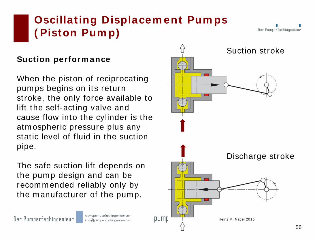
Oscillating Displacement Pumps (Piston Pump)
Suction stroke
Discharge stroke
Suction performance When the piston of reciprocating pumps begins on its return stroke, the only force available to lift the self-acting valve and cause flow into the cylinder is the atmospheric pressure plus any static level of fluid in the suction pipe. The safe suction lift depends on the pump design and can be recommended reliably only by the manufacturer of the pump.
Heinz M. Nägel 2016

Suction Behavior of Oscillating Pumps
57
The Net Positive Inlet Pressure [Pa]) head required by the pump is NPIPR (R: required). It describes which minimum net positive inlet pressure Δ pi has to be overcome in the pump. To ensure that this pressure head can be overcome without cavitation, the suction system has to provide the NPSA (A: available) including a certain safety factor S at the suction flange of the pump. Therefore, the following generally applies: SNPIPRNPIPA or NPSHRNPSHA. The minimum safety factor S is 10 % of the maximum vapor pressure. The NPIPA considers •the maximum of the sum of all pressure losses in the system •the difference in height which has to be overcome •the barometric pressure •the vapor pressure pd •the container excess pressure pe and •the flow velocity vB in the suction tank.
Heinz M. Nägel 2016

• NPSHA m Holding pressure of the plant • Hp m Pressure head of environment or tank • Hz m Inlet head • HR m Head of friction and other flow loss • HV m Vapor pressure head • HS m Safety
58
NPSHA of the Plant

59
Example of NPSHA

pe p1
p1
pe
pd
NPSHA NPSHR
S
∆p = ς ⋅ S ⋅ ρ 2
d 2
2
∆p = λ ⋅ L ⋅ ρ ⋅ w
H
plus : ∆p = ρ ⋅ a ⋅ L
L
ζ λ ζ
Variants and Multiplex Pumps Suction Conditions: NPSHA / NPSHR
60
∆pm = ρ⋅g⋅L
w2
Heinz M. Nägel 2016

Oscillating Displacement Pumps NPSH (additional)
61
Heinz M. Nägel 2016

Copyright FELUWA Pumpen GmbH 62 Heinz M. Nägel
Classification into homogeneous and heterogeneous mixtures

Copyright FELUWA Pumpen GmbH 63 Heinz M. Nägel E 2110601
Homogeneous suspension with high solids content
Fly & bottom ash (heterogeneous)
Basic Consideration
Heterogeneneous mixture (settled)
Oscillating Displacement Pumps Hydrotransportation of Heterogeneous Mixtures

Copyright FELUWA Pumpen GmbH 64
FG
FA
FW
wS
FT
w wK
Vertical upward delivery In order to allow for the delivery of the particle, the sum of efficient forces has to feature a positive force component. Transportation forces counteract the settling speed of the solids. At a flow velocity of the carrier fluid the solids are transported at the following speed: In the event that the flow velocity of the carrier fluid (w) falls below the settling speed of the particles (Ws), sedimentation of solids will start.
Reciprocating pump system (Sedimentation)
Heinz M. Nägel 2016 Heinz M. Nägel 2016

Copyright FELUWA Pumpen GmbH 65
Diaphragm Piston Pumps Diaphragm Failure Caused by Sedimentation
No. E 2102021-2 Heinz M. Nägel
Sedimentation of conveyed fluid cause diaphragm rapture!
If the flow velocity of the carrier fluid falls below the settling speed of the particles, sedimentation of solids will start and cause a Diaphragm Failure

Copyright FELUWA Pumpen GmbH 66
Unique Modular Design for fluids with high differential density.
Heinz M. Nägel 2016
Foliennr.
Traditional flow direction from the bottom to the top for fluids with lifting velocity, which is applied for products with floating tendency.
The unique DFT Technology (reversed pumping) is specified for products with specifically heavy particles in the carrier fluid that tend to settle and are accordingly difficult to be sucked in.
Oscillating Displacement Pumps MULTISAFE Double Hose-Diaphragm Pump

Copyright FELUWA Pumpen GmbH 67 Heinz M. Nägel
Foliennr.
With DFT (Downflow Technology) the traditional pumping principle is literally turned upside down, which means that the flow is directed from the top to the bottom. By this means, settling of solids within the pump can realiably be avoided. The consistent modular construction system allows for individual adaptation, even on site.
MULTISAFE® Double Hose-Diaphragm Pump (Downflow configuration)

Copyright FELUWA Pumpen GmbH 68
MULTISAFE Double Hose-Diaphragm Pump - Downflow Transport -
Downflow Configuration for the hanling of particularly heavy solids
and heterogeneous mixtures
Downflow Configuration =
Flow from the top to the bottom of the pump
Downflow (DFT) configuration is the solution against
sedimentation inside the pump
Heinz M. Nägel No. E 2201014-2

Copyright FELUWA Pumpen GmbH 69 Heinz M. Nägel E 2201186-1
Summery Directions for pump selection and design
What kind of solids carrying fluids are to be handled?
Which requirements are to be met by the pumps?
Energetic and volumetric efficiencies are basic criteria for the suitability!
The higher the volumetric efficiency, the higher the energetic efficiency as well as flow and metering accuracy and wear resistance.
High noise level of the pump means that
« it defends itself against application or service conditions » !
In case of high viscosities (particularly with particles) it is essential to keep the deformation of the natural flow lines as little as possible.
The higher the efficiency, the more gentle the pumping process because the entire energy
loss is transferred to the fluid by means of the shearing effect.
Results : Pump wear, damage to the conveyed fluid !
With low viscosities, maximum energetic efficiency is achieved if the volumetric efficiency is likewise at maximum and internal leakage at minimum, respectively.
Wear is regarded as indicator.

Copyright FELUWA Pumpen GmbH 70 Heinz M. Nägel E 2201186-1
Summery What does the future hold?
Cost pressure and the changing environmental awareness in process technology have significantly increased in the past few years. As a consequence, demands for safety, efficiency, reliability, availability and diagnostics of the pumps have also increased considerably. These criteria are directly connected with the costs for production downtime, spare parts, service and maintenance. The future challenges for pump manufacturers are rising, since the adaptation to the 4th Industrial Revolution (Industry 4.0/networking)/China 2025 and its consequences create assessment criteria will change a lot. The technical and economic value and the traceable operating experiences will have a major influence on strategy and investments.
Copyright FELUWA Pumpen GmbH
Heinz M. Naegel, FELUWA
Many thanks for your attention
My reports are based on my longtime experience. I am convinced, that displacement pumps will become more and more important
in a time of continuously increasing energy costs.
“Oscillating Displacement Pumps Performance and Characteristics of positive displacement pumps”Positive
Displacement Pumps