
ORM.-1227 Progress Report
214
si s Ul *:* it ; • *' • ORM.-1227 Progress Report oak Ridge National Laboratory x- OPERATED BY Carbide and Carbon Chemicals Company A DIVISION OF UNION CARBIDE AND CARBON CORPORATION H33 POST OFFICE BOX P OAK RIDGE. TENNESSEE
Transcript of ORM.-1227 Progress Report

si
s
Ul*:*
it ;
•-
*'
•
ORM.-1227
Progress Report
oak Ridge National Laboratory x-OPERATED BY
Carbide and Carbon Chemicals CompanyA DIVISION OF UNION CARBIDE AND CARBON CORPORATION
H33POST OFFICE BOX P
OAK RIDGE. TENNESSEE

Sfcfc,.
v.
ORNL-1227
This document consists of 214 pages
Copy (pfo of 222. Series A.
Contract No. W-7405-eng-26
AIRCRAFT NUCLEAR PROPULSION PROJECT
QUARTERLY PROGRESS REPORT
FOR PERIOD ENDING MARCH 10, 1952
R. C. Briant, Director
A. J. Miller, Assistant Director
Edited by:
W. B. Cottrell
DATE ISSUED
MAY 7 1552
OAK RIDGE NATIONAL LABORATORY
operated by
CARBIDE AND CARBON CHEMICALS COMPANY
A Division of Union Carbide and Carbon CorporationPost Office Box P
Oak Ridge, Tennessee
MARTIN MARIETTA ENERGY SYSTEMS LIBRARIES
3 M45b 005072b 2

11
2
3
4.
5.
6.
7.
8.
9.
10.
11.
12.
13.
14.
15.
16.
17.
18.
19.
20.
21.
22.
23.
24.
25.
26.
27.
28.
29.
30.
31.
32.
33.
34.
A.
R.
F.
J.
A.
D.
C.
J.
G.
C.
W.
D.
W.
W.
G.
A.
W.
C.
w.
A.
A.
W.
R.
G.
C.
M.
F.
E.
J.
C.
C
R.
H.
D.
W.
E.
M.
H.
E.
B.
D.
K.
K.
T.
P.
R.
B.
R.
Ho
S.
B.
J.
W.
P.
T.
Ke
M.
A.
E.
INTERNAL DISTRIBUTION
Adamson
Barton
BillingtonBlizard
asunas
riant
uce
Bu^CalH;hanCardwe\ll
Center
Cisar
Clewett
Clifford
Cottrell
Cowen
Eister
ErgenFelbeck (C&CCC)Fraas
Gall
Graham
Grimes
11aender
Household
Humes (Jones
Keilh
Keim
Keljteyr te
K^hgane
arson
35.
36.
37.
38.
39.
40.
41.
42.
43/M%.
/ 45.
/ 46.47.
48.
49.
50.
51.
52.
53.
54.
55.
56.
57.
58.
59.
60.
62.
63.
64.
ht J.i. z.E. J.
H.
R.
E.
0.
A.
F.
R.
C.
J.
E.
F.
F.
A.
C.
cDonald
Meem
Miller
MorganMurphy
H. F. PoppendiekP. M. Reyling
W. SavageW. Schroeder
D. ShipleySisman
H. Snell
SteahlyStoughtonSusano
Swartout
TaylorUffelman
VonderLageWeinbergWinters
Biology LibraryChemistry LibraryHealth Physics LibraryMetallurgy LibraryPhysics LibraryTraining School LibraryANP Libraryentral Files
entral Files (O.P.)

%5W
/ 191.
/ 192-193.f 194-197.
198-207.
208-222.
EXTERNAL DISTRIBUTION
Argonne National Laboratory:med Forces Special Weapons
)mic Energy Commission, WasBafctelle Memorial Institute
Broolfchaven National Laborj^oryBureau'^f AeronauticsBureau ofvShipsCarbide and\Carbon CJ^micals Company (Y-12)Chicago Paten\ GrcChief of Naval "B^BearchduPont CompanyGeneral Electee Company, Oak RidgeGeneral Elcy^ric Company, RichlandH. K. FerjpTson Company\Hanford^Kerations Office;Idaho {operations OfficeIowa/Scate CollegeLocXjftnd Area Office, AEC \
. s Atomic Power Laboratory;Alamos v
isachusetts Institute of Technology (Kaufmann)found Laboratory \[ational Advisory Committee for Aeronautics, Cleveland
National Advisory Committee for Aeronautics, WashingtonNew York Operations Office \North American Aviation, Inc. vPatent Branch, Washington \Savannah River Operations Office \University of California Radiation LaboratoryWestinghouse Electric Corporation \Wright Air Development Center xTechnical Information Service, Oak Ridge \
5ject (Sandia)lgton

IV
Reports previously issued in this series are as follows:
ORNL-528 Period Ending November 30, 1949
ORNL-629 Period Ending February 28, 1950
ORNL-768 Period Ending May 31, 1950
ORNL-858 Period Ending August 31, 1950
ORNL-919 Period Ending December 10, 1950
ANP-60 Period Ending March 10, 1951
ANP-65 Period Ending June 10, 1951
ORNL-1154 Period Ending September 10, 1951
ORNL-1170 Period Ending December 10, 1951
Sri*'
>«*^

TABLE OF CONTENTS
FOREWORD
PART I. REACTOR THEORY AND DESIGN
SUMMARY AND INTRODUCTION
1. CIRCULATING-FUEL AIRCRAFT REACTOR
Reactor with Tandem Heat Exchangers
Reactor with Annular Heat Exchangers
Reactor Shield Designs
Design procedure
Activation of the secondary coolant
Shield weights and specifications
2. CIRCULATING-FUEL AIRCRAFT REACTOR EXPERIMENT
Core Design
Primary coolant circuit
Secondary coolant circuit
Core temperature distribution
External Fluid Circuit
Pumps
Heat exchangers
Primary coolant system
Secondary coolant system
Monitoring circuit
Preheating System
Reactor assembly
Piping
1
3
5
7
7
9
9
9
11
11
13
13
15
15
16
16
16
18
18
18
18
18
19
19

Heat exchangers
Electrical Power Circuits
Control System
Shim control
Regulating and safety rods
High-temperature fission chamber
Control console and panel
Reactor dynamic computer
Instrumentation
Building
3. EXPERIMENTAL REACTOR ENGINEERING
Seals and Closures
Frozen sodium seal
Frozen fluoride seal
Bellows type of face seal for ARE pump
Stuffing-box seals for molten fluorides
Lubrication of seals and shafts
Pumps
ARE centrifugal pump
Laboratory frozen-fluoride-sealed centrifugal pumpWorthite frozen-sodium-sealed pumpModified Durco centrifugal pumps
Forced-convection-cooled sodium-sealed pumpsCanned-rotor pumps
Valves
Packing-gland seal test equipment
VI
19
19
20
20
20
21
21
21
21
22
23
23
24
24
24
25
26
26
26
27
27
27
29
29
29
29
-.,,J
\^2JI»-'
Hi.-'
V.
Frozen fluorides valve
Ball check valves
Valve seat test
Heat Exchangers
Aircraft type of radiator
Sodium-to-air radiator
Fluoride-to-fluoride heat exchanger
NaK-to-NaK heat exchanger
Heat transfer in circulating fluoride loops
Instrumentation
Flow measurement
Pressure measurement
Temperature measurement
Level controls and level indicators
Heating and Cooling of High-Temperature Systems
External heating systems
Induction heating
Resistance heating
Insulation testing
ARE core preheating
Technology of High-Temperature Liquids
Fluoride preparation and handling
Sampling and analyzing techniques
Diffusivity of helium through stainless steel
Cleaning and inspection techniques
4. REACTOR PHYSICS
Circulating-Fuel Aircraft Reactor
30
30
30
30
30
31
31
32
32
33
33
34
34
34
35
35
36
36
36
37
37
37
39
39
39
41
41
VII

Oscillations
Slow kinetic effects
Critical mass
Neutron leakage spectra
Alkali Hydroxide Moderated Aircraft Reactor
Survey Calculations of the Circulating-Fuel ARE
ARE core design
Critical mass and total uranium investment
Reactivity coefficients
Power distribution
Neutron flux and leakage spectra
Statics of ARE Controls
Shim control requirements
Regulator rod
Safety rods
Specific Design Problems of the Circulating-Fuel ARE
CRITICAL EXPERIMENTS
Direct-Cycle Reactor
Control rod calibration
Temperature effects
Reflector studies
Graphite Reactor
Circulating-Fuel Reactor
Correlation of Theory and Critical Experiments
Criticality with nonhydrogenous moderators
Criticality with hydrogenous moderators
Vlll
42
44
44
46
48
48
48
50
50
51
52
54
54
54
55
57
59
59
59
61
61
62
62
63
63
65
Vrt*'
n**^

w
Foil exposures
Danger coefficients
Rod sensitivity
Gap experiment
PART II.
SUMMARY AND INTRODUCTION
6. BULK SHIELDING REACTOR
Mockup of the Divided Shield
Reactor Calibration
7. DUCT TESTS
Theoretical Treatment of Duct Transmission
Measurement of Air-Filled Ducts in Water
Straight ducts
Ducts with bends
Comparison with theory
8. TOWER SHIELDING FACILITY
Tower Facility Design
Experimental Program
9. NUCLEAR MEASUREMENTS
Measurements with the 5-Mev Van de Graaff Accelerator
Total cross section of iron
Inelastic scattering levels in iron
Time-of-Flight Neutron Spectrometer
Background measurements
Indium resonances
SHIELDING RESEARCH
65
66
66
68
69
71
73
73
76
79
79
80
80
80
80
89
89
89
93
93
93
93
93
93
94

PART III. MATERIALS RESEARCH
SUMMARY AND INTRODUCTION
10. CHEMISTRY OF HIGH-TEMPERATURE LIQUIDS
Low-Melting-Fluoride Fuel Systems
NaF-BeF2-UF4KF-BeF2-UF4RbF-BeF -UF
2 4
LiF-NaF-BeF2-UF4Fuel containing zirconium fluoride
Simulated Fuel Mixture for Cold Critical Experiment
Ionic Species in Fused Fluorides
Preparation of Standard Fuel Samples
Preparation of Pure Hydroxides
Coolant Development
LiF-ZrF„4
NaF-ZrF„
KF-ZrF„
RbF-ZrF„4
NaF-KF-ZrF,
NaF-RbF-ZrF4
NaF-KF-LiF-ZrF.4
Preparation of Pure Fluorides
Fuel preparation equipment
Fuel handling equipment
11. CORROSION RESEARCH
Static Corrosion by Fluorides
95
97
99
99
100
101
101
101
101
102
102
103
104
104
105
105
105
105
105
105
106
106
106
107
109
110
•-W

Nhwa*"
Effect of pretreatment of fuel
Corrosion of structural metals
Corrosion by fluorides with various additives
Melting point of fluorides after corrosion tests
Static Corrosion by Sodium Hydroxide
Corrosion of special alloys
Corrosion by sodium hydroxide with various additives
Corrosion of refractory materials
Static Corrosion by Liquid Metals
Corrosion by low melting point alloys
Corrosion by sodium-lead alloy
Facilities for Dynamic Corrosion Testing
Thermal convection loops
Seesaw corrosion tests
Differential temperature tests
Rotating dynamic corrosion tests
Forced convection loops
Dynamic Corrosion by Fluorides
Corrosion by fluorides in thermal convection loops
Corrosion by fluorides in a seesaw furnace
Standpipe tests of fluoride corrosion
Dynamic Corrosion by Hydroxides
Corrosion by hydroxides in thermal convection loops
Corrosion by sodium hydroxide in seesaw tests
Standpipe tests of sodium hydroxide corrosion
Fundamental Corrosion Research
Possible equilibria among fluorides and metals
110
110
112
113
114
114
115
116
116
116
118
119
119
120
120
120
122
122
122
124
124
127
127
129
129
129
132
XI
EMF measurements in fused fluorides
Electrode potentials in fused sodium hydroxide
Polarography of sodium hydroxide in silver and platinumMagnetic susceptibility of stainless steel exposed to fluorides
12. METALLURGY AND CERAMICS
Fabrication of Reactor Elements
Cold drawing of tubular solid fuel elements
ARE control rod
Cone-Arc Welding
Equipment
Principle of operation
Experimental procedure
Brazing
Flow tests
Corrosion of brazing alloys
Mechanical Testing of Materials
Inconel creep and stress data
Tube-burst tests
Operation of creep and stress-rupture equipment
Ceramics Laboratory
Ceramic applications to reactors
Coatings for the radiator
Ceramic laboratory equipment
Microscopic examination of fluorides
13. HEAT TRANSFER AND PHYSICAl PROPERTIES RESEARCH
Viscosity of Fluoride Mixtures
135
135
136
136
139
139
140
140
142
142
142
142
143
144
144
147
147
148
148
151
151
151
152
152
153
153
-.. &#
„J

Hfaj^"
Viscosity of NaF-KF-LiF
Viscosity of NaF-KF-LiF-UF4
Modifications of viscosity apparatus
Thermal Conductivity of Liquids and Solids
Heat Capacities
Vapor Pressure of Liquid Fuels
Physical Property Data
Natural Convection in Confined Spaces with Internal Heat Generation
Analysis of Heat Transfer in a Circulating-Fuel System
Heat Transfer Coefficients
Heat transfer in molten lithium
Heat transfer to fused salts and hydroxides
Entrance region heat transfer in a sodium system
Heat Transfer of Boiling Liquid Metals
14. RADIATION DAMAGE
Irradiation of Fused Materials
Pile irradiation of fuel
Cyclotron irradiation of fuel
Inpile Circulating Loops
Creep Under Irradiation
Radiation Effects on Thermal Conductivity
PART IV. APPENDIXES
SUMMARY AND INTRODUCTION
15. THE SUPERCRITICAL-WATER REACTOR
153
154
154
154
155
155
156
156
159
161
161
161
161
162
163
163
164
165
165
165
166
167
169
171
Xlll

Description of Reactor
Conclusion of the NDA Study
Recommendations of the NDA Study
16. ANALYTICAL CHEMISTRY
Studies of Diatomaceous Earth
Analytical Studies of Fluoride Eutectics
Uranium
Beryllium
Total alkali metals
Total fluoride
Nickel
Chromium
Manganese
Silicon
Solubility of Boric Acid in Water
Clarity of Borated Water
Studies of Alkali and Alkaline Earth Hydroxide Coolants
Analytical Services
17. LIST OF REPORTS ISSUED
18. DIRECTORY OF ACTIVE ANP RESEARCH PROJECTS AT ORNL
Reactor and Component Design
Shielding Research
Materials Research
Technical Administration
xiv
171
171
172
175
175
175
176
176
176
176
177
177
177
177
177
177
178
178
179
183
183
185
186
191
Si.gjir

v»-
v...
LIST OF FIGURES
FIGURE TITLE
1 Tandem Heat Exchanger Arrangement for Circulating-Fuel Reactor
2 Annular Heat Exchanger Arrangement for Circulating-Fuel Reactor
3 Circulating-Fuel ARE Core Design
4 Arrangement of External Fluid Circuit Equipment
5 Frozen Fluoride Seal Tester
6 ARE Centrifugal Pump
7 Ball Check Valve
8 Schematic Diagram of Circulating-Fuel Aircraft Reactor
9 Leakage Spectrum Through the Reflector of the Circulating-FuelAircraft Reactor
10 Leakage Spectrum Around the Fuel Pipes of the Circulating-FuelAircraft Reactor
11 Critical Mass vs. Core Diameter for Hydroxide Reactors withThick Reflectors of the Same Composition
12 Power Distribution in the Core of the Circulating-Fuel ARE
13 Leakage Spectrum from the Reflector of the Circulating-Fuel ARE
14 Leakage Spectrum from the Open Ends of the Circulating-Fuel ARE
15 Transverse Neutron Flux Spectrum for Three Sections Through theCore of the Circulating-Fuel ARE
16 Radial Neutron-Flux Distribution in the Core of the Circulating-Fuel ARE
17 Loading Chart of Critical Assembly of Direct-Cycle Reactor
18 Reactivity as a Function of Control Rod Position
19 Reactivity vs. Temperature
PAGE
8
10
14
17
25
28
30
45
46
47
49
52
53
53
54
55
60
61
61
xv

FIGURE
20
21
22
23
24
25
26
27
28
29
30
31
32
33
34
35
36
TITLE
Relative Position of Reactor, Divided Shield, and Gamma-RaySpectrometer in Bulk Shielding Facility
Gamma-Ray Spectra at 130 cm from the Water-Reflected Reactor
Fuel Assembly Arrangement of Bulk Shielding Facility Reactor
Center Line Measurements of Neutron Transmission ThroughCylindrical Ducts in Water
Traverse Measurements of Neutrons in Water Beyond CylindricalDucts
Center Line Measurements of Neutron Transmission in WaterThrough Cylindrical Ducts with Variable Bends
Traverse Measurements of Neutrons in Water Beyond CylindricalDucts with Variable Bends
Comparison of Relative Source Strengths (nQ) from Various DuctsComparison of Relative Source Strengths (n ) from VariousGeometries of the 3-in.Duct
Proposed 300-ft Tower Shielding Facility
X-6 Aircraft Shield Mockup on Tower Shielding Facility
Total Cross Section of Iron
Corrosion of Inconel in a Fluoride Fuel [(NaF-KF-UF ) + 2% 7rlfor 100 hr at 816°C 4
Intergranular Attack of Type-310 Stainless Steel Tested in 44%Lead-56% Bismuth Alloy for 100 hr at 1500°F
Alloying Attack of Inconel Tested in 43% Tin-57% Bismuth Alloyfor 100 hr at 1500°F
Seesaw Apparatus for Dynamic Corrosion Tests
Sections of Hot and Cold Legs of an Inconel Convection Loop AfterCirculating the Fluoride Fuel (NaF-KF-LiF-UF4) for 500 Hours
PAGE
74
75
77
81
82
83
84
87
88
90
91
94
113
117
117
121
125
•»•,«/

w
FIGURE TITLE PAGE
37 Sections of Hot and Cold Legs of a Type-316 Stainless SteelConvection Loop After Circulating the Fluoride Fuel(NaF-KF-LiF-UF4) for 123 Hours 126
38 Nickel Thermal Convection Loop Operated for 117 hr with SodiumHydroxide Under an Air Atmosphere 128
39 Nickel Thermal Convection Loop Operated for 296 hr with SodiumHydroxide Under a Hydrogen Atmosphere 130
40 Inconel Thermal Convection Loop Operated for 135 hr withPotassium Hydroxide Under a Hydrogen Atmosphere 131
41 Sectional View of L-Nickel Specimen after 117 hr (14,000 cycles)with Molten Sodium Hydroxide in Seesaw Apparatus 132
42 Transverse Sections Through 4-in. OD, Cold-Drawn, Tubular,
Solid Fuel Elements 141
43 Corrosion Test of Nicrobrazed Inconel Tube-to-Header Specimens
Exposed to NaOH for 100 hr at 1500°F 145
44 Corrosion Test of Nicrobrazed Inconel Tube-to-Header JointExposed to NaF-KF-LiF-UF4 for 100 hr at 1500°F 146
45 Corrosion of Inconel Tube-to-Header Joint Brazed with a 60%
Manganese-40% Nickel Alloy after 100 hr at 1500°F in NaOH 147
46 Creep and Stress-Rupture Data for Fine-Grained Inconel Sheet 149
47 Creep and Stress-Rupture Data for Coarse-Grained Inconel Sheet 150
48 Dimensionless, Wall-Mixed Mean Temperature Difference as aFunction of Reynold's and Prandtl's Moduli for a Heat TransferSystem with Insulated Pipe Walls 160
49 Heat Transfer Coefficients for Boiling Mercury 162
50 Comparison of Bench and Inpile Creep Rates of Nickel 166

<^%
'^j*^

TABLE
1
2
3
4
5
6
7
8
9
10
11
12
13
14
15
16
17
18
LIST OF TABLES
TITLE
Shields for Circulating-Fluoride-Fuel Reactors
Fuel Temperature After Each Pass Through Core
Performance of Fluoride-to-Fluoride Heat Exchanger
Analysis of Heater Section (Model A-l)
Composition of Various Fluoride Fuels and Coolants
Volume Fractions of the Circulating-Fuel ARE Core and Reflector
Uranium Requirements of the ARE
Reactivity Coefficients
Shim Control Requirements
Comparison of Control Rod Calibrations
Reactivity Change Introduced by Substituting Beryllium for Air
Reactivity Change Effected by Substituting Plastic and StainlessSteel for Beryllium in the Reflector
Experimental Data on Critical Assemblies 1 and 4
Calculated Results for Critical Assemblies 1 and 4
Comparison of Experimental and Calculated Values of the Ages ofThermal Neutrons in Peryllium and Graphite
Experimental and Calculated Values for the Cadmium and Cadmium-Indium Ratios
Experimental and Calculated Values for the Total Loss in kupon Introduction of Various Materials into Assembly 4
Comparison of Calculated Effective Source Strength for Straight,Cylindrical Ducts
PAGE
12
16
32
33
38
50
50
51
56
61
62
62
64
64
64
66
67
85
xix

TABLE
19
20
21
22
23
24
25
26
27
28
29
30
31
32
33
34
xx
TITLE
Comparison of Calculated Effective Source Strength for Bent,Cylindrical Ducts
Improvement of Count-to-Background Ratio with Aluminum andBeryllium Filters
PAGE
86
94
Comparison of Break Temperatures from Heating and CoolingCurves of the System NaF-BeF2-UF4 100
Break Temperatures from Cooling Curves of the System KF-BeF2-UF4 101
Break Temperatures from Cooling Curves of the System RbF-BeF2-UF4101
Break Temperatures from Heating and Cooling Curves of Zirconium-Bearing Fuel Mixtures
Disposition of Standard Fuel Samples
Static Corrosion of Various Materials in the UntreatedFluoride Fuel (NaF-KF-LiF-UF4) in 100 hr at 1500°F
Static Corrosion of Inconel and Type-309 Stainless Steel bythe Fluoride Fuel (NaF-KF-LiF-UF4) with Magnesium and Zirconium Additives in 100 hr at 1500°F
Melting Points of Samples of Fluoride from Corrosion Tests
Static Corrosion of Structural Metals by Sodium Hydroxidewith Various Additives in 100 hr at 1500°F
Melting Points of Various Alloys
Corrosion of Types-310 and -317 Stainless Steel and Inconelby Various Low Melting Point Alloys in 100 hr at 1500°F
Corrosion Data from Inconel and Stainless Steel Thermal Convection Loops Operated with Various Fluorides
Free Energies and Equilibrium Constants for Reactions ofMetals with Alkali Fluorides
Free Energies and Equilibrium Constants for Reduction ofUranium Tetrafluoride with Metals
102
103
111
112
114
115
116
118
123
133
134
~%t0
%-wSP'

^dfc9S*e"
TABLE TITLE PAGE
35 Viscosity of NaF-KF-LiF-UF4 Mixtures as a Function of UraniumTetrafluoride Concentration 154
36 Physical Properties of Fluoride Salts 157
37 Physical Properties of Miscellaneous Materials 158
38 LITR Tests on Fused Fluoride Fuels in Inconel at 1500°F 164
39 Summary of Service Analyses 178

•Vfts^1
ANP PROJECT QUARTERLY PROGRESS REPORT
FOREWORD
This is the quarterly progress report of the Aircraft Nuclear PropulsionProject at the Oak Ridge National Laboratory and summarizes the technicalprogress on the project during the period covered. It includes not only thework of the Laboratory under its own contract, W-7 40 5-en g-26, but also theresearch for the national ANP program performed by Laboratory personnel. Thereport is divided into four parts: I. Reactor Theory and Design; II. ShieldingResearch; III. Materials Research; and IV. Appendixes. Each part may^beregarded as a separate entity and has a separate "Summary and Introduction."

y-w**^.
wwtmtmt* mmw iniwimn"m mcmM*

Part I
REACTOR THEORY AND DESIGN


SUMMARY AND INTRODUCTION
Analysis of the circulating-fue1 3). The techniques of the prepara-aircraft reactor has been extended tion, purification, and handling ofto systems incorporating intermediate the fluoride mixtures have beenheat exchangers, various secondary developed so that 100-lb batches ofcoolants, liquid moderators, and the the treated fluoride may be prepareduse of heavier reactor shielding and loaded in adequately cleaned test(sec. 1). All these systems utilize equipment. Techniques of pumping,the fundamental advantage of the bi - sealing, and controlling the fluoridefunctional fue1-coolant, and appear to coolants and lubricating moving partsbe capable of supersonic nuclear of the systems have been demonstratedpropulsion. The location of the heat at temperatures above 1300 F, and itexchangers around the reactor results is considered that these techniquesin lower shield weight, even with a are adequate for ARE application,larger shielded-volume diameter, than A centrifuga1 -flow fluoride pump hasa tandem reactor and heat exchanger operated for weeks with neither rearrangement. In order to perform a chanical failure nor leakage. Liquidlimited amount of aircraft maintenance sodium technology appears to be wellwithout special shielding, various in hand, since continued success hmodifications of the minimum divided been experienced in the operation ofshield specifications have been in- sodium (or NaK) pumps, seals, and heatvestigated. exchangers. The NaK-to-NaK heat ex
changer loop has now operated for 2300„ , . j- i r j hr with a maximum temperature of 1500°F.Studies of the performance and r . ,.
„ . . , . r i • Gross heat transfer studies indicatedesign of the circulating-tue 1 air- ,
° rr- • , that space-economica1 systems andcraft reactor are sufficiently en- r , ,,
. i r- a• r^ components can be built to handlecouraging that the first Aircraft y , „a„^a„ rT /-adc\ u copious quantities of heat, as requiredReactor Experiment (ARE) to be con- .
. ,/ , _ , D., NT . i by fluoride systems, at temperaturesstructed by the Oak nidge National ' nonn j ionn°c, , -ii , r i • / between 12UU and loUU r.Laboratory will be of this type Isec.2). The reactor core, as designed for The reactor physics calculations,the ARE, consists of a beryllium oxide which have further defined the staticsmoderator with a multipass fuel-coolant of the circulating-fuel ARE, have ledsystem. The core and a surrounding to some general observations regardingberyllium oxide reflector are contained the kinetics of both the circulating-in an Inconel pressure shell. Design fuel ARE and ANP reactor (sec. 4).of the reactor, fluid circuits, build- Although the thrombosis effect is aning, and associated equipment are important concern in the control ofessentially complete. The reactor is these reactors, the loss of the delayedexpected to be in operation early in neutrons may not be if the circulation1953. / of the fuel itself is as good a damping
mechanism as now indicated. TheseThe developmental work in reactor kinetic difficulties are of less con-
plumbing and associated hardware has cern to the ARE than to the ANP, sincebeen primarily concerned with the the circulation rate in the ARE is sotechnology of high-temperature fluoride slow that the control rods can copemixtures, and a secondary effort has with the thrombosis effect and a large
^ been the study of liquid metals (sec. fraction of the delayed neutrons are
as

ANP PROJECT QUARTERLY PROGRESS REPORT
emitted into the active volume. The Electric direct-cycle reactor havecurrent ARE design has a critical mass been completed and the simulated cir-of 22.3 lb, a total uranium investment cu la t in g - f ue 1 reactor is now beingof 74 lb, 71% thermal fissions, and a assembled (sec. 5). Evaluations, inleakage-to-absorption ratio of about terms of contributions to reactivity,1 to 3. Brief studies of hydroxide have been made of several reflectormoderated reactors (including KOH, modifications of the direct-cycleLiOH, NaOH, RbOH, and SrOH) show that, assembly. In addition, the data fromexcept for KOH, the hydroxide moderated the earlier graphite reactor assemblyreactors require low critical masses have been correlated with the dataand small core volumes for minimum from theoretical calculations of thecritical mass. assembly. The correlation lacks
precision but gives results that areMeasurements on the critical ex- at least consistent with the experi-
periment of the simulated General mental facts.

>»«»'
FOR PERIOD ENDING MARCH 10, 1952
1. CIRCULATING-FUEL AIRCRAFT REACTOR
A. P. Fraas, ANP Division
A circulating-fuel aircraft reactorsystem in which the fluid fuel circulates directly through the turbojetradiators was described in the lastreport. ''' Other circulating-fuelaircraft reactor systems, incorporatingsuch features as intermediate heatexchangers, various secondary coolants,the use of liquid moderators, andheavier reactor shieIding,have beenconsidered in an attempt to determinethe most practical system for a functional supersonic aircraft. All thesesystems utilize the fundamental advantage of the bifunctional fuel-coolant - the elimination of a heattransfer stage within the react or core.
Two series of shielded, full-size,circulating-fuel aircraft designs havebeen studied; one involves an annular,or "wrap-around," type of heat exchanger, and the other is a tandemarrangement with the heat exchangerbehind the reactor. Analyses showthat the annular arrangement givesthe lower shield weight. These designstudies brought forth the importanttechnique of lacing the heat exchangermatrix with about 8 vol % B4C tokeep the radiation from sodium orNaK in the secondary circuit totolerable values even with something
approaching a unit shield.
It also appears from these studiesthat it would be advantageous to usea liquid moderator such as water orfused hydroxides. Not only would theproblem of cooling the moderator andreflector be greatly simplified, butby using perhaps a 12-in.-thick reflector, the problem of heating of the
'^B. W. Schroeder, "Ci rcul a t ing- Fue1 AircraftReactor," Aircraft Nuclear Propulsion ProjectQuarterly Progress Report for Period EndingDecember 10, 1951, ORNL-1170, p. 7.
pressure shell by gammas, neutroncaptures, and inelastic scatteringwould be greatly reduced. More detailed studies of the practicabilityof design for cooling the structurewith a liquid moderator have beeninitiated.
REACTOR WITH TANDEM HEAT EXCHANGERS
The first basic configuration considered was one in which the reactor
core and the intermediate heat exchanger were placed in tandem. Alongitudinal section of a tandem reactor and heat exchanger arrangementis shown in Fig. 1. A basic premisewas that by interposing the heat exchanger between the pumps and the reactor core, a uniform fl ow distributionamong the fuel tubes would be assured.The design required that the liquidfluoride fuel flow through the tubesin the reactor core at 11 ft/sec foroperation at 400,000 kw with a temperature rise through the reactor of 400 F.The basic layout is best adapted to aliquid moderator (i.e., H20 or NaOH)from the standpoint of fabrication andof means for cooling the moderatorand reflector.
In this design, the fuel enters thereactor at the top rear, makes a complete loop through the fuel tubes inthe core, and discharges to the heatexchanger. The fuel tubes are ofstainless steel with 1 1/2-in. ID and0.015-in. wall thickness. If water
were the moderator, a double-wa1ledconstruction could be used. It may benoted that if the inner tube (containing circulating fuel) ruptured orcracked, the only fuel lost would bethe amount that filled up the spacebetween tubes before it froze in
contact with the cold outer tube.

\*J
''/2-in. MINIMUM HgO LAYER AT 300-350 psi AROUNDENTIRE REACTOR AND HEAT EXCHANGER CASTINGS
DWG. E-Y-F7-17IR1
EXCHANGER AND PUMP HOUSINGS
5/e-in. THICK ALUMINUM
in. STEEL PLATE FOR REACTOR AND
REQUIRED
FUEL PUMP
HOUSING
Pig. 1. Tandem Heat Exchanger Arrangement for Circulating-Fuel Reactor.
\, M
>
nsSOo<_<
noH
Oc•90HMSOr
90O
SOMt»(Z)
SOH•0osoH
^*as«*^

FOR PERIOD ENDING MARCH 10, 1952
The water (or hydroxide) moderator type of design, the concentric helicalenters the active lattice around the coil carrying the NaOH moderatorperiphery of the rear of the reactor through the reactor core is interest-and flows toward the outlet at the ing because it eliminates a head er
forward end of the reactor. As the problem. By using perhaps tan tubemoderator flows in it is distributed fittings, welds at the ends of theseby a baffle sheet that is orificed coiled tubes could be avoided so thatto give the flow distribution required a material such as molybdenum mightby the power distribution within the be used,active lattice.
The control system for this proposed REACTOR SHIELD DESIGNScirculating-fuel reactor design consists of two curtains of cadmium rods Ifc ls lmPortant to know the effectsmounted on two endless tracks. The °^ various parameters on the weightcurtains are moved from the reflector °^ tne aircraft reactor and shield,into the active lattice by an endless ^ut ifc is difficult to determine thesechain-sprocket type of mechanism. effects quantitatively since the pres-Each cadmium rod is mounted upon two ent knowledge of shielding does notsteel shafts with stee 1 rollers attached permit weight estimates closer thanto the ends of the shafts. These ±5%, at best. However, engineeringrollers are linked together to form designs have been completed for thean endless chain. The sprocket is shields for the preceding reactor
^^ driven by a worm-gear drive, which in arrangements, and rea 1 weight di fferencesturn is driven by a hydraulic pump tnat result in lighter weight shieldsmounted within the pressure shell. for tne annular arrangement than forEach cadmium rod is a cylinder ap- the tandetn arrangement have been foundproximately 1/2 in. OD by 1/4 in. ID to exist- In the shield weights cal-by 12 in. long, and there are about 50 culated the use of B4 C in the heatrods in each control curtain. exchanger and between the reactor and
heat exchanger has been found to substantially reduce the activity of the
REACTOR WITH ANNULAR HEAT EXCHANGERS secondary coolant.
The second basic configuration Design Procedure. The primaryconsidered was a reactor with an objective in the design of theseannular, or "wrap-around," type of shields was to minimize the activationheat exchanger such as shown sche- of the secondary coolant by delayedmatically in Fig. 2. Radial webs are neutrons from the fuel. This has beenused both to separate the annular heat effected by (1) attenuating the neutronexchanger into sectors and to support leakage from the active lattice to athe shell around the outside of the level below that of the delayed neu-reflector. To permit assembly, the trons in the heat exchanger, andreactor pressure shell would have to (2) lacing the heat exchanger withbe split axially, probably on the enough neutron absorbing materialcenter line. The pressure shell and (B4C) so that relatively few neutronsother structures are jacketed and would be absorbed in the secondarycooled by NaOH at around 1200°F. A coolant. The header sheet and a 5-in.heat exchanger to cool the NaOH is B4C layer between core and heat ex-
^ provided in the region where the NaK changer was sufficient to reduce theenters the pressure shell. Although neutron leakage flux to the heat ex-not an essential element in this general changer, whereas the use of B C in

NaK INLET
NaOH-NaK HEAT EXCHANGER
'/80D TUBES ON %2 C-<L.SQ PITCH
NaOH PUMP
HEAT EXCHANGERINLET MANIFOLD
NaK INLET
DWG. E-Y-F7-2I30RI
NaK OUTLET
HEAT EXCHANGER
OUTLET MANIFOLD
Ve STEEL
STEEL
0.060 STEEL
— 2 PRESSURE SHELL
CANNED IN
0.060 STEEL
NaOH
-'/, STEEL
HEAT EXCHANGER OUTLETLINE, 6 REQ'D
NaK OUTLET
NOTE:DIMENSIONS ARE IN INCHES
Fig. 2. Annular Heat Exchanger Arrangement for Circulating-Fuel Reactor.
o
no
90©
n
3oe•so
90r
"099O
(/}
90MHBO90H
u

FOR PERIOD ENDING MARCH 10, 1952
every ninth tube in the heat exchanger were assumed to be 50%, the dose atserved to supress the activity of the 1.5 meters (5 ft) from the center ofcirculating fuel. the source would be 200 r/hr after
long periods of operation at a reactorThe balance of the shield design heat output of 400,000 kw.
work was straight-forward and followedthe procedures outlined by the Shield- The activation of a quite differenting Board. (2) Both Lid Tank and Bulk coolant, a fused salt consisting ofShielding Facility test data were used. approximately 60% LiCl, 30% MgCl2,The fission-product-decay gamma rays and 10% KC1, was also estimated. Al-for the equilibrium f is s i on-pr oduct though with no B4C in the heat ex-concentration at full power were taken changer the activity of this fusedas being equivalent to three 1.0-Mev salt was only 5% of that of the NaK,gamma rays and one-half of a 3.0-Mev the activity for the case with the B4Cgamma ray per fission. in the heat exchanger was 35% of that
of the NaK. Thus, it appears thatActivation of the Secondary Coolant. there is little to be gained from the
The degree of activation of the second- shielding standpoint in the use ofary coolant is, of course, a function this molten chloride in place of NaK.of the materials in that coolant.Since NaK (56% Na and 44% K) has many Shield Weights and Specifications.advantages as a high-temperature heat Several engineering designs of shieldstransfer medium, and since it would have been completed for both the tandemprobably be about as bad from the and annular heat exchanger arrange-activation standpoint as any coolant ments. For either reactor arrangementthat could be used, an estimate of its the divided shield resulted in theactivation was made with the heat ex- lowest shield weight. However, thechanger shielded and laced with B4C as desire to be able to carry out aoutlined above. It was found that if limited amount of airplane maintenance25% of the NaK in the system were work without special shielding arguesconsidered as concentrated at a point in favor of more shielding around theand the self-absorption of the sodium- reactor. The various shield designsdecay gamma rays released in the air for the two reactor and heat exchangerradiator or other similar component arrangements are given in Table 1.
For comparable shields the annularheat exchanger and reactor assembly
'2'Report of the ANP Shielding Board for the Air- o-iv Ps aDDreciablv lower weight thancraftNuclear Propulsion Program, NEPA-ORNL, ANP-53, g <= HH /October 16, 1950. the tandem arrangement.
11

Details in report
Date of design
Reactor shield diameter (in.)
Crew shield weight (lb)
Weight of reactor, intermediate heat exchanger, andreactor shield (lb)
Total weight of reactor, intermediate heat exchanger,and all shielding (includingcrew shield) (lb)
Reactor power (kw)
Diameter of reactor core (in.)
Liquids in primary and secondary circuits
Temperature loss in intermediate heat exchanger ( F)
Pressure loss in intermediateheat exchanger (psi)
Crew shield size (ft)
Reactor-crew separationdistance (ft)
Radiation inside crew compartment (r/hr)
Radiation 5 ft from centerof reactor (r/hr)
Radiation 50 ft from centerof reactor (r/hr)
Radiation 300 ft from centerof reactor (r/hr )
%ta#^
TABLE 1
Shields for Circulating-Fluoride-Fuel Reactors
TANDEM HEAT EXCHANGER PARTIALLY DIVIDED
1
Y-F15-10
Jan. 1952
150
5,000
151,000
156,000
400,000
32
Y-F15-10
Jan. 1952
150
11,000
130,000
141,000
400,000
32
Fluoride-NaK Fluoride-NaK
100 100
100 100
6% x 7% x 12% 6% X 7% x 12%
50 50
1 1
300 2,400
7 36
1 6
Y-F15-10
Jan. 1952
121
36,000
75,000
111,000
400,000
32
Fluoride-NaK
100
100
6% x TA x 12%
50
1
380,000
5,600
156
)
Y-F15-10
Jan. 1952
121
14,000
75,000
89,000
400,000
32
fluoride-NaK
100
100
5 X 5 X 12%
120
1
380,000
5,600
156
ANNULAR HEAT EXCHANGER
PARTIALLY DIVIDED
1
Y-F15-10
Feb. 1952
148
5,000
123,000
128,000
400,000
32
Fluoride-NaK
100
50
6% X 7% X 12%
50
1
300
7
1
Y-F15-10
Feb. 1952
118
36,000
62,000
98,000
400,000
32
Fluoride-NaK
100
50
6% X 7% X 12%
50
1
380,000
5,600
156
>
*o
1390O<-i
wr>H
Oc
99Hffl90r*!
1390O«90mt/><z>
90n13O90H

("'"-'FOR PERIOD ENDING MARCH 10, 1952
2. CIRCULATING-FUEL AIRCRAFT REACTOR EXPERIMENT
R. W. Schroeder, ANP DivisionE. S. Bettis, Reactor Projects Division
The studies of the circulating-fuel The helium is cooled by passage throughaircraft reactor using fused fluoride four helium-to-water heat exchangershave culminated in the design of two and the water - the ultimate heataircraft reactor systems (one with and source - is discharged.one without an intermediate heat ex- Control of the reactor is providedchanger), both of which are potential .n threg formS) Q) ghim control> (2)power plant systems for supersonic regulating rodSj and (3) safety rods.nuclear propulsion. Furthermore, these ^^ control ig achieved by varyingaircraft reactor systems appear to ^ uranium concentration in the circu-permit higher performance than the lating fue1. One boron rod, whichsodium-cooled reactor, primarily be- passeg through the core center lineandcause of the bifunctional capacities ef f ect s. app r oximat el y 0.75% Afe/fe,of the primary coolant, which is the gerves ag the regulating rod. Thecirculating fuel. Consequently, the boron safety rods, equally spaced
t ARE to be constructed by the Oak Ridge ^^ the center of the cor6i haveNational Laboratory at Oak Ridge will approximately 5% Afe/fe per rod.be a circulating-fuel type of reactor.
The circulating fuel of the reactor CORE DESIGNwill be a mixture of molten alkalimetal fluorides plus uranium fluoride. The core design is illustrated byThe structural metal of the core and Fig. 3. It may be noted that thecontainer shell will be Inconel, since over-all assembly includes an Inconelthis metal has been on order for the pressure shell in which beryllium oxideliquid-metal ARE and currently appears moderator and reflector blocks are„t least as corrosion resistant to the stacked and through which fuel tubes,circulating fluorides as any of the reflector coolant tubes, and controlstainless steels. The reactor can assemblies pass. The innermost regionadvantageously be moderated with of the lattice is the core, which is aberyllium oxide, which is also cur- cylinder 3 ft in diameter and 3 ftrently available for the previously long. The core is divided into sixcontemplated liquid-metal ARE. 60-degree sectors, each of which in
cludes 13 vertical stacks of hexagonalThe power is generated within the beryllium oxide blocks. Each sector
circulating fuel as it is passed includes one serpentine, fuel-tubethrough the beryllium oxide moderated coil, which passes through the 13core. The core is provided with a moderator stacks in series, as il-beryllium oxide side reflector, which lustrated. The six serpentine coilsis housed with the core within an are connected in parallel by means ofInconel pressure shell. The reflector external manifolds,and pressure shell are cooled by aseparate circuit using a mixture of A reflector with a nominal thick-nonuranium-bearing fluorides. Power ness of 6 in. is located between theis abstracted from the fuel by means core and the pressure shell on theof four fuel-to-helium heat exchangers cylindrical surface only. The re-through which the fuel is circulated. flector consists of beryllium oxide
13
a

BOTTOM HEAD-
CORE SUPPORT
STRUCTURE-
FUEL OUTLETMANIFOLD
ASSEMBLY
CONTROL RODASSEMBLY
CORE AND REFECTORCOOLANT OUTLET PIPE
( ROTATED 30 DEGREESFROM TRUE POSITION )
BOTTOM TUBE
SHEET, 1 THICK-
NOTE:
ALL DIMENSIONS
IN INCHES -7.500
DWG. E-Y-F7-202 R1
WELD BACK-UP RING
- COOLANT ANNULUS, LCORE AND REFLECTORV|6 THICK CAN, V,6 THICK
35.250 ACTIVE LATTICE
34.500 --48.500-
Fig. 3. Circulating-Fuel ARE Core Design.
^
-CORE AND REFECTOR COOLANTINLET (SHOWN ROTATED 30 DEGREES
FROM TRUE POSITION )
REINFORCING PLATES
-THERMAL INSULATION
-FUEL INLETMANIFOLD
- FUEL TUBE WELDING JOINT
' FUEL TUBESt.235 OD, 0.060 WALL
-TOP HEAD
"TOP TUBE SHEET
-REFLECTOR COOLANT TUBE0.500 OD , 0.020 WALL
2<v
woH
o
90
gor•<
"090Oo
8(*>CO
90m
s90H
\kjp

v„
blocks similar to the moderator blocksbut with %-in. holes for the passage ofreflector coolant. The reflector
coolant enters at one end of the
pressure shell, passes through thereflector, bathes the pressure shelland fills the moderator interstices,and exits at the other end of the
pressure shell.
Primary Coolant Circuit. Hydro-dynamic and thermodynamic considerations have influenced the design tosuch an extent that a discussion of
these problems appears to be desirableprior to description of the primarycoolant circuit itself. In a circulating-fuel type of reactor, heat isgenerated in the flowing fuel. Theparticle heat generation is dependenton the particle residence time withinthe reactor. As the flow proceedsthrough the tubes, the velocitiesadjacent to the walls are lower thanthe bulk mean velocities, so that thefuel particles adjacent to the wallsare subjected to higher temperaturerises. This effect is mitigated byconvection within the fuel stream, buta temperature difference will existbetween the wall and the stream
center line. Studies have indicated
that this temperature difference isdirectly proportional to the fuelpower density, tube diameter, Prandtl'snumber, and Reynold's number. Application of these studies to variouspostulated ARE configurations haveestablished that excessive temperaturedifferences are encountered in the
laminar flow region (Reynold's numberbelow 5000) but that small temperaturedifferences are encountered in the
turbulent flow region. Consequently,the reactor core was designed for aReynold's number of 10,000, therebyallowing for some deviation of flowrate or fluid physical properties.
The design for a straight- throughflow core arrangement was revisedbecause the calculated Reynold's
FOR PERIOD ENDING MARCH 10, 19 52
number was less than 1000. Con
sideration of the parameters for increasing Reynold's number indicatedthat the desired correction would
entail increasing tube diameter, increasing the number of tubes in series,increasing the volumetric flow rate,or decreasing the volume of fuel within the core, or combinations thereof.Investigation of these variables ledto the observation that a few series
passes would be required even withmaximum feasible exploitation of theother variables. Since this was the
case, and since the design problemsinvolved in the use of many seriespasses appeared to be similar to thoseassociated with the use of a lesser
number of series passes, it was decidedto use 13 series passes and avoidcompromising the volumetric flow rateor the core fuel volume.
Secondary Coolant Circuit. The useof a liquid circuit other than thefuel circuit within the pressure shellis desired for the following reasons:(1) to maintain the pressure shellessentially isothermal at a temperature of approximately 1150°F; (2) tocool the beryllium oxide reflectorwith a fluid other than circulating
fuel; and (3) to fill the berylliumoxide moderator interstices and otherinternal voids with a liquid maintainedat a pressure higher than the fuelpressure to prevent a fuel tube leakfrom adding reactive material to thecore. The liquid to be used has to becompatible with the structural materialunder dynamic conditions and shouldcause no undesirable reaction with
the fuel in the event of a leak in the
separating wall. At the present timeit is believed that nonuranium-bearingfluorides, perhaps the fuel carrierwithout the UF4, will best meet thesespeci fications.
The possibility of cooling themoderator by positive flow of thisfluid through the moderator interstices
15

ANP PROJECT QUARTERLY PROGRESS REPORT ^
has been studied. It has been found, There are two sources of heat forhowever, that the mass flow through a the fuel circulating through thegap of constant periphery varies as the reactor: internal heat generationthird power of the gap width (in the (from fissionand gamma-ray absorption)laminar flow region, with fixed and heat transferred to the fuel frompressure drop). Temperature analyses the remainder of the core. The heatwith postulated gap width distributions transferred from the remainder of theindicated that gross temperature core is produced in the followinginequalities could exist throughout manner. Heat is generated in thethe moderator because of tolerance moderator and the parasitic coreaccumulations affecting interstice material as a result of gamma-raywidths. Accordingly, it has been absorption, and additional heat isdecided to obstruct flow through the generated in the moderator by neutronmoderator so as to render it virtually slowing down. All this heat is trans-stagnant. The moderator heat then is ferred to the circulating fuel andconducted to the fuel stream, and thus results in a temperature gradienta relatively accurate analytical across the fuel, moderator, anddetermination of moderator tempera- parasitic material,tures can be obtained.
Core Temperature Distribution. Thecirculating fuel in the ARE core flows EXTERNAL FLUID CIRCUITin parallel through six serpentinetubes, each tube traversing the core The ARE fluid circuit> intended to ^13 times. In passing through the core handle toxic and corrosive fluids at *^13 times, the fuel is heated from 1500°F, requires a considerable amount1150 to 1500°F. The calculated mixed of design and developmental effort,mean fuel temperatures at various Where Possible, commercially availablestations in the reactor are given in components are used, but pumps, heatTable2. exchangers, and certain other com
ponents are being constructed es-TABLE 2 pecially for the ARE. The location of
Fuel Temperature after each Pass the maJor sYstem components, includingThrough Core t'ie reactor pits, the heat exchanger
room, the reactor, and the two heatMIXED FUEL disposal loops, is illustrated, in
STATION TEMPERATURE (°F) Fig. 4. It may be noted that the heatexchanger room is shielded from thereactor pits to permit servicing after
Leaving pass No. 1 1171 fuel drainage and flushing. The2 1191 shield was designed to minimize3 1211 activation of fluid circuit structure
4 1233 by reactor neutrons during power5 1257 operation and to attenuate reactor
6 1281 post-shutdown gamma rays to a level7 1305 permitting access to fluid circuit8 1335 components after shutdown.9 1365
10 1392 Pumps. The pumps to be used in the11 1426 fuel and moderator coolant circuits "^112 1462 are vertical-shaft, t angen t i a1- di s - ^"^13 1500 charge, centrifugal pumps in which a
16
Entering reactor 1150

f
UNCLASSIFIEDDWG O-Y-FTZO-701
7? ROD COOLING EXCHANGER".-'.••>••.
-28ft-0 in. -
Fig. 4. Arrangement of External Fluid Circuit Equipment.
OSO
13PI58I—I
Oa
tn
aM
58n
MS
to

ANP PROJECT QUARTERLY PROGRESS REPORT
gas seal is used and the liquid level capable of dissipating 1500°F kw.is maintained. The gas seal is formed Within each loop the fuel divides intoby a floating graphite ring between two parallel 750-kw fu e1- to - he 1iu...the stationary nose on a bellows seal heat exchangers and then passes throughand the hardened rotating nose on the a centrifugal pump to a common returnshaft. The primary pump seal carries trunk (Fig. 4).no appreciable pressure differentialand, consequently, requires that the In an individual loop, helium flowsoil-circulating system above the seal from a centrifugal blower through abe pressurized to balance that of the fuel-to-helium exchanger in which thecirculating system below the seal. The temperature of the helium is increasedcirculating oil serves to cool the from 250 to 750°F. The helium is thenshaft, bearing, and lower seal. In cooled to 250°F in a helium-to-wateraddition, internal cooling of the exchanger from which it passes throughstructure is obtained by the circu- another heating and cooling cycle andlation of helium. Another feature of is returned to the blower. This so-the pump is that the entire rotating called "double-sandwich" arrangementassembly can be put together outside permits two helium heat transports perthe pumping casing, and in event of cycle and thereby halves the heliuma failure it can be installed with flow rate required through the blowercomparative ease. and ducting for a specified power and
temperature rise.Heat Exchangers. The fuel-to-
helium heat exchangers are on order Secondary Coolant System. Thewith the Griscom-Russell Company; they reflector and pressure shell coolantwere designed by Griscom-Russell to system, as in the case of the fuelORNL specifications. The heat ex- system, is divided into two heatchangers are of the cross-flow type disposal loops, each capable ofwith the fuel flowing through l-in.-OD, handling the load associated with0.109-in. wall Inconel tubing. The 1500-kw reactor power. Heat istubing is finned on the gas side with conveyed from the primary coolant tostainless steel, helically wound helium and then to the water sink,strips. Each heat exchanger includesfive parallel tube banks; each bank Monitoring Circuit. All lines andconsists of seven to nine horizontal components containing fue 1 or reflectortubes in series with integral return co-blant are do ubl e- j acke t ed, withbends. The fuel inlet and outlet helium passing through the annulus.headers are constructed of 4-in. pipe The helium pumping head is maintainedto which the five tube banks are by drawing helium from the system,w d# cooling it, and admitting it to rotary-
type compressors at various points inThe helium-to-water heat exchangers the system as indicated. Monitoring
also are finned-tube, cross-flow ex- for fluoride leaks into the helium ischangers, but steel tubes with copper achieved by passing helium samplesfins are used. through halogen detectors.
Primary Coolant System. Fuel flows
from the six core tubes to a common PREHEATING SYSTEMheader, and a common trunk line conveysthe fuel into the heat exchanger room. The relatively high melting pointsIhe fuel then divides into two com- of the circulating fuel and secondarypletely independent loops, each cool an t (around 752 to 932°F, depending
m

FOR PERIOD ENDING MARCH 10, 19 52
upon the particular fuel composition) the pipe surface tends to cause largerequire that all equipment within temperature valleys to exist betweenwhich these coolants are to be main- the points of heat application. Bytained be preheated to permit loading attaching electrical resistance heatersand unloading. to the outer pipe of the double-
walled piping, however, the flowingReactor Assembly. The insulation helium acts as a thermal conveyor and
heat leakage at operating temperature facilitates axial heat transporthas been calculated to be approximately Accordingly, substantially isothermal15 kw, and the heat capacity of the helium contacts the inner pipe and itassembly has been established as is thus possible to heat the pipeapproximately 4000 Btu per °F. After uniformly,having studied various preheatingmethods, including pumping hot fluids Heat Exchangers. The fuel-to-through the fuel passages or through helium heat exchangers require pre-the moderator interstices, it was heating prior to filling and thedecided that the simplest method addition of heat to compensate forentailed the application of electrical thermal leakage during filling or atresistance heaters to the outside of any time after filling when the fuelthe pressure shell, withheat transport pumps are inoperative. These heatto the inner regions by conduction. exchangers have a total of approxi-With a constant heat input of 14 kw, mately 40 ft2 of exposed free-flowin addition to the insulation losses, area (both upstream and downstream),it is estimated that the assembly can which, if allowed to radiate to thebe heated from room temperature to adjacent cold structure, would dissi-1200°F in approximately four days. pate approximately 40 kw when theWith this heat input rate, certain tubes are at 1325°F. Accordingly, itcalculated temperature gradients are appears necessary to include radiationas follows: barriers in the form of gates that can
be lowered during warm-up or zero- or
1. Across pressure shell, 20°F, low-power operation. When theseradiation barriers are in position,
2. Across helium gap between shell the fuel-to-helium heat exchangers areinside diameter and reflector outside enclosed and may be preheated bydiameter, approximately 100°F, means of hot helium supplied by the
external piping annuli.3. From reflector outside diameter
to core center line, approximately250°F.
ELECTRICAL POWER CIRCUITS
Piping. The heat capacity of thepiping is small relative to the piping Because of the extreme incon-insulation leakage. Consequently, the veniences associated with forcedpower required to preheat the piping reactor shutdown, fuel drainage, re-is substantially the same as the power filling, and restarting, the objectiverequired to maintain it at the ultimate has been to design the system so thattemperature. If the 1iquid-bearing no one failure will necessitate apipes are empty, as is the case during forced shutdown. Critical pumpspreheating, the pipe resistance to blowers, etc. are duplicated, and eachaxial heat flowishigh, and the appli- set is served by an independent d-ccation of heat to specific points on circuit that includes independent
19

ANP PROJECT QUARTERLY PROGRESS REPORT
w
buses, switches, and a-c-d-c motor- behavior is currently being analyzedgenerator sets. The use of direct cur- on the analogue computor.rent for these circuits permits convenient speed con trol where required and Shim Control. Fuel enrichment willthe use of battery sets floating on the be accomplished by adding enrichedline to safeguard against outside molten fuel at the surge tank. Thepower failures. Alternating-current molten concentrate will be introducedinstruments are fed from the d-c through a small (%-in.) line, which,circuits via d-c-a-c mo tor-gen erator by means of a video pickup device, cansets so that these instruments will be observed from the control roomderive their power from the batteries while fuel additions are being made,in an emergency. The fuel-enrichment mechanism has been
laid out in elementary form. TheThe heat capacity of the system is principles of operation have been
large relative to the heat leakage established, but the tanks, weighingrate, so that no large temperature devices, valves, heaters, etc. haveloss will be incurred for about 6 hr not been detailed. This system isin an emergency. Consequently, it is mUch simpler than was first thoughtnot necessary to use battery power for possible and it makes possible a safesystem heat addition. System heaters, and relatively easy technique oftherefore, are connected directly to bringing the reactor to critical afterthe 440-v a-c circuit. Similarly, the the initial loading,building crane and certain other items
will not need to be operative during Regulating and Safety Rods. Because ^any short period in which it is neces- of the low power density of the circu- "^sary to use battery power, so these lating-fuel ARE, the temperaturecomponents are supplied by the 440-v coefficient of the fuel must bea-c system. supplemented by a s e r v o - a c t u a t e d
regulating rod if transient conditionsare to be controlled. This servo willoperate in exactly the same manner as
The ARE is controlled by three the fuel temperature coefficient. Theessentially separate systems: (1) error slS"al that actuates the servoregulating, (2) shim, and (3) safety. Wl1/ be a miXje,d S1gnal of temperaturea i • i i .. • , • and neutron flux; it is given by theA mechanical regulating rod is pro- . B '
• , , • ^, r , equa t i onvided, since the time - cons tants oi the
se1f-stabi1izing effects of the fuelexpansion in the ARE are too long to e = (# . Q, ) + 58.5 (p - p )provide stiff control of the reactor. l l °Shim control is conveniently effectedby the addition of higher-uranium whereconcentration fuel to the circulating-fuel volume. £ = error signal ,
Specifications for the control ®i " ^i,o = reactor inlet error inconsole and panel have been released °Fwith a specified delivery date of ,October 1, 1952. The high-temperature (p - p0) = reactor power error infission chamber has operated at1292°F, megawatts (the factor ^and an MTR-type servo for the regulat- 58<5 is in °p per mega. Wing rod has been ordered. The kinetic watt).
20
CONTROL SYSTEM

FOR PERIOD ENDING MARCH 10, 1952
When e < 0 the servo withdraws the rod, Control Console and Panel. Completeand when e > 0 the servo inserts the specifications for the components ofrod. This servo equation is different the control room have been released,from that previously reported as a including detailed construction draw-result of a change in reactor design. ings and fabricationa1 and material
specifications. Sets of these specifications have been mailed to ten pros-
A change has been made in the pective bidders, and the bids are tolocation of the drive mechanisms for received by March 1. The instructionsthe regulating and safety rods. They to bidders specified that the completewill not be located over the reactor order is to be filled by October 1,pit, and they will have straight 1952.linkages to the rods. This changewill allow considerable simplification The items covered in these drawingsof the over-all mechanical control and specifications include an operatingsystem. console, instrument racks, relay racks,
recorders for nuclear measurements,
amplifiers, power supplies, andAn MTR-type servo has been ordered assorted mounting hardware. Items not
for the regulating rod. The regulat- covered in this outside order areing rod and safety rod designs have nuclear chambers, some preamplifiers,been determined and the fabrication of servos, and process instruments. Thethese rods has been turned over to the order takes care of from 90 to 95% ofMetallurgy Division. After fabri- the electronic equipment needed forcation, the rods will be run in the the ARE."cold" critical assembly to determinetheir worth. Calculations indicatethat the safety rods are worth approxi-m
Reactor Dynamic Computer. Theentire circuit of the ARE has been
mately 5% Afe/fe , and the regulating. , , , i , j _ u .-u put on the analogue computer, and
rod will be loaded so as to be worth , , . , , r f« „ ^~ a, /i ,-, r .. j the kinetic behavior ot the system is
about 0.75% Afe/fe. One safety rod , , n , .. , '. , , r- • . . being analyzed. The analysis is not
operating mechanism has been finished , , , , •, , ,. , r™ • ii yet complete, but the »ork is pro-by the machine shop. This assembly . . ., , • , •
' , , . , , eressing satisfactorily and lndi-has not been tested, but the design B & .'
, . . cations are that a fairly compre-seems to be satisfactory. , . , .,, , r„„„ *.u;„' hensive study will result from this
work. This computer analysis hasreceived the full attention of two
High-Temperature Fission Chamber. . ,„ , , , , ... engineers for the past eight months.The fission chamber has been operated e reat 700°F but no insulator material hasbeen found that will withstand highertemperatures. A design is in progress INSTRUMENTATIONthat eliminates the insulator in thehigh-temperature region. This chamber A basic purpose of the ARE is thehas not been tested and there is no acquisition of experimental data, socertainty that it will function the importance of compl ete and reliableproperly. Because of the uncertainty instrumentation cannot be over-of high-temperature operation of the emphasized. Most ARE process in-fission chambers, sufficient cooling strumentat ion is intended to observeis being provided to maintain the and record rotational speeds, flow
V„ chambers at 400°F, where it is known rates, temperatures, pressures, orthey will function. liquid levels. In the low-temperature
21

ANP PROJECT QUARTERLY PROGRESS REPORT
loops, this equipment is sufficientlyconventional to obviate the need fordetailed descriptions. The high-temperature loops involve specialsensory problems, however, which maymerit some discussion. In someinstances several alternate sensoryprinciples are under development concurrently. No attempt will be made todescribe each of these alternatemethods in detail in this report;however, the various techniques thatare being used or developed are outlined in the section on "ExperimentalReactor Engineering" (sec. 3).
22
BUILDING
The building to house the ARE isproceeding on schedule. Additionalcontracts have been negotiated withthe contractor to complete work notspecified in the original contract,and this new work is to be completedso that the building can be releasedto ORNL by June 1, 1952. The auxiliarypower specifications have been completed and orders for the equipmentare being released. An elementaryelectrical diagram for this equipmenthas been drawn.
,»-#
""^•jig^

FOR PERIOD ENDING MARCH 10, 1952
'X...-
3. EXPERIMENTAL REACTOR ENGINEERING
H. W. Savage, ANP Division
Liquid metals, hydroxides, and these devices has made it necessarymixed fluorides are being investigated to provide auxiliary heating to avoidas heat transfer media and fuels for freezing of the coolant,aircraft reactor experimentation attemperatures of 1200 to 1800°F. Some Heating and cooling of liquiddevelopmental effort on the use of metals, hydroxides, and mixed fluoridessodium and sodium-potassium alloy are being investigated from roomcontinues, although the effort on the temperature to 1800°F. The hightechnology of molten fluoride mixtures, melting temperatures of hydroxidesas required by the circu lating-fue1 and fluorides have introduced pre-reactor, predominates. The develop- heating, insulation, and operationalment of fluoride systems is limited complexities, since it is desirableby the corrosion problem (see sec. 11 to avoid freezing of the coolant and"Corrosion Research"). Chemical and possible bursting of containers uponphysical treatment of fluoride com- remelting. Heat transfer studies atponents to eliminate contaminants temperatures at which the materialsand improving handling, storing, and are molten thus far appear to betransfer techniques to avoid reintro- straightforward, and the technologyduction of contaminants are being advances at the rate at which the
**•«•" studied as means of limiting corrosion. controlling physical properties aredefined.
The applicability of known methodsof pumping, sealing, controlling, and Equipment performance is improvingmeasuring properties and quantities markedly, and a number of mechanicalof these high-temperature coolants and and other devices for fluorides havefuels is being investigated. The high- been operated for periods exceedingtemperature reactor systems, however, 1000 hr in some cases without visibleplace unique restrictions on materials, equipment damage and without leakage,lubricants, leakage, and performance Heat exchangers are being designedof mechanical devices and associated for aircraft and laboratory applica-equipment. Pumping has been accom- tion, and the NaK-to-NaK heat exchangerplished with conventional hydraulic has now operated for over 2000 hr atdesigns, but alleviation of thermal 1500°F. Flow, volume, pressure, anddistortions and stresses, cooling of temperature control appear to bebearings, and the development of straightforward if care is exercisedliquid- and gas-tight seals have been at the high temperatures involved,required. Alleviation of thermal distortions and the development of liquid-tight seals have also been required SEALS AND CLOSURESfor valves. In addition, the valvesmust contain seal materials that will Frozen-s od ium-se a led pumps havenot interdiffuse in the presence of operated over extended periods, andthe coolant at high temperatures. frozen fluorides that have been usedLubrication of the moving parts of for sealing shafts show considerablethese devices at high temperatures promise of giving satisfactory service.
^»- has been accomplished. The cumbersome, The metallic braid with self-containedand at times massive, geometry of packing lubricant appears to be highly
23

ANP PROJECT QUARTERLY PROGRESS REPORT
satisfactory for use with moltenfluorides. Controlled isolation of
two sections of a fused salt systemhas been accomplished by the use of a"freeze valve." Welded or metal-
gasketed joints are used in pipingsystems. Improved weld designs andwelding techniques that allow fullpenetration of weld metal have madepossible the operation of equipmentwithout failure for extended periods.Flanged joint seals with oval-ringgaskets have proved satisfactory foroperation at temperatures to 1300 F.
Frozen Sodium Seal. The frozen-
sodium-sealed pump reported in thelast quarterly report' ' has operatedapproximately 1500 hr during thisquarter without failure of the frozensodium seal. A modified Durco cen
trifugal pump has been constructedthat has a finned sleeve for forminga frozen sodium seal by means of con-vective cooling.
Frozen Fluoride Seal (W. B. McDonald
and P. W. Smith, ANP Division). Anadditional 160 hr of testing was accomplished during this period with thefrozen fluoride seal previously reported' ' (Fig. 5). Initial testswere conducted to determine whether
a frozen fluoride seal is feasible,and additional tests were conducted
to determine (1 ) the effect of fluorideson the Ste11ite-coated shaft around
which the seal is formed; (2) themaximum pressure that can be sealedwithout leakage; (3) the problemsencountered in starting the shaft afterit has been stopped and the fluoridespermitted to freeze around the shaft;and (4) the determination of designand operational parameters with this
H. W. Savage, "Experimental ReactorEngineering," Aircraft Nuclear Propuls ion ProjectQuarterly Progress Report for Period EndingDecember 10, 1951, ORNL-1170, p. 42.
'2'W. B. McDonald, "Seal Tests," op. cit.,ORNL-1170, p. 43.
24
type of seal. These tests indicatethat greater clearance is desirablebetween shaft and cooling sleeve thanwas used in the frozen sodium seal.
A build-up of magnetic, metallicmaterial, from 1 to 2 mils thick, wasfound on the shaft and cooling sleeve.Several shallow surface scratches were
found on the shaft; however, thesewere no more severe than those normallyencountered with stuffing-box packingmaterials. A significant differencewas found between a frozen fluoride
seal and a frozen sodium seal; whenrotation is stopped and fluorides arepermitted to freeze around the shaft,it is necessary to apply heat to theshaft in order to free it for continued
operation. Maximum pressure limitsfor this seal were not determined;however, the seal was operated against60-psi pressure, which is satisfactoryfor the operation of the ARE.
Bellows Type of Face Seal for ARE
Pump. Sealing of the ARE pump isaccomplished by two bellows type offace seals installed in series. The
seal below the bearing space consistsof a graphite ring floating betweentwo hardened, metallic sealing faces,one on the nose of the bellows and the
other attached to and rotating withthe sha ft.
Sealing against the atmosphere isaccomplished by the conventional lappedface seal above the bearings. Thisarrangement permits the lower seal,which must operate at higher temperatures, to operate with no pressuredifferential across it and thus
lengthens the life of the seal. Thisarrangement would also permit completeisolation of the system from theambient atmosphere in the pump roomif leakage should occur in the primaryseal.
The temperature of the upper high-pressure seal can be easily controlled
<**%.

and should present no problem. Anyleakage of bearing lubricant into thesystem would be trapped immediatelybelow the seal and could be easilyremoved from the system.
FOR PERIOD ENDING MARCH 10, 1952
Stuffing-Box Seals for Molten
Fluorides (H. R. Johnson, ANP Division). Thin-walled bellows have thusfar been unsatisfactory for sealingagainst high-temperature fluorides
UNCLASSIFIEDDWG. 14424
SHAFT (316 STAINLESS STEEL, STELLITE COATED)SUPPORTED BY OUTBOARD BEARINGS AND DRIVEN
BY V-BELT-
THERMOCOUPLE
THERMOCOUPLE
THERMOCOUPLE
THERMOCOUPLE
LEVELINDICATOR -
FLUID LEVEL
THERMOCOUPLEWELL
0.060-in. CLEARANCE
FINNED SLEEVE, TYPE-316STAINLESS STEEL
SPACER
GAS PRESSURE
THERMOCOUPLE
GAS PRESSURE APPLIED
TO THIS SURFACE
POT, TYPE-316STAINLESS STEEL
Fig. 5. Frozen Fluoride Seal Tester.
25

ANP PROJECT QUARTERLY PROGRESS REPORT
owing to metal and weld failures. Astuffing-box seal for a valve stemhas been developed that will furnisha positive seal against fluorides at1500 F. Such a seal has operatedsatisfactorily and has sealed againstfluid pressures to 50 psig. The sealconsists of a conventional type ofstuffing box in which successive layersof Inconel braid, graphite, nickelpowder, and another layer of Inconelbraid are packed under compressionaround a shaft. A conventional stainless steel globe valve with the stempacked in this manner has operatedduring this period for more than 700hr at 1500°F and 30-psi pressure andis still in operation.
The molten fluorides pump describedin the following is sealed with a conventional stuffing-box arrangement byusing four rings of commercial-graphite-impregnated asbestos packing separatedby Teflon washers. The washers aremachined from Teflon bar stock, sinceit has been determined that sheetTeflon formed by extrusion or rollingprocesses has a "memory" for its pre-extruded shape and at elevated temperatures tends to return to this shape.The stuffing box is surrounded by acooling coil through which refrigeratedethylene glycol is circulated.
Lubrication of Seals and Shafts
(H. R. Johnson, ANP Division). Testsindicate that when the valve stem sealdescribed above is lubricated periodically (a few drops each week) withtricresyl phosphate (a compound usedfor lubricating wire-drawing dies),friction is reduced to the point wherethis high-temper ature valve can beoperated with as little friction as astandard valve operated at room temperature .
Further tests show that when such agland is packed with Inconel braid andfinely powdered UF4 is substituted forthe nickel and graphite powders, a
26
shaft can be rotated at 1000 rpm withthe entire assembly heated to 1500°Fwith no damage to the shaft.
According to the Celanese Corporation of America, extensive tests indicate that tricresyl phosphate hasapproximately six times the filmstrength of a lubricating oil of approximately the same viscosity. Continuous heating at well over 200°F inin the presence of air is required tobring about decomposition. "The lubricating effect of tricresyl phosphateon iron is believed to be due to formation of iron phosphide Fe3P."(3) Avalve stem lubricated periodically (afew drops once a week) with tricresylphosphate has operated 660 hr, and itremains very easy to turn.
PUMPS
Development of a mechanical pumphas progressed to the point wherereliable operation can be expected inforced-circulation systems containingeither liquid metals or molten fluorides with fluid temperatures in thepump as high as 1300°F. Designs havebeen completed, and fabrication ofpumps, which are expected to operatereliably at 1500°F or above, is underway. All pumps tested to date are oflaboratory size; however, pumps designed to meet ARE flow and head requirements have been designed and areto be fabricated.
ARE Centrifugal Pump (W. G. Cobb,G. F. Wislicenus, J. F. Haines, andA. G.Grindell). The ARE fluid circuitconsists of two pumps in the circulating-fuel system and two pumps inthe moderator coolant system. Thehead and flow requirements for each of
( 3 )J. J. Bikerman, Surface Chemistry for
Industrial Research, p. 369, Academic Press,1948.
^m\
W^1

FOR PERIOD ENDING MARCH 10, 1952
these pumps are identical. Each must circulate fluids at temperatures indeliver approximately 45 gpm with a excess of 1500°F.head of approximately 45 ft of fluidpumped. Two models have been proposed Worthite Frozen-Sodium-Sealed Pumpand designed for ARE service. (W" Bl McDonald and W. R. Huntley).
The Worthite centrifugal pump modifiedThe ARE centrifugal pump, Model D, t0 incorP°rate the frozen-sodium seal,
requires a gas seal, whereas ARE cen- Resting of which was described m thetrifugal pump, Model F, has a frozen last rePort' has been transferredfluoride seal. The design features fr°m an "othermal looP to operationof Model D were described in the last ln a fl/u/e-8 loop. This pump hasquarterly report. The assembly of this f^"?6*1 f°rL &t0tal °f aPProxlmatelypump is shown in Fig. 6. The Y-12 15°° hr Wlth no seal fallure- Occa-shops are presently in the process of slonal shutdowns for repair have beenfabricating three Model D pumps from paused by the mass transfer of coppertype-316 stainless steel. The Model fr°m the Sasket used t0 seal the Part-F frozen-fluoride-sealed pump is almost "*g faC,eS of. the pULmP to the shaft inidentical to the Model D pump, with the cold section of the sealing annulus.the exception of the inclusion of a T\1S resulfced in a build-up on thegas-cooled section in which the fluo- sleeve> *hlch filled the annulus andrides surrounding the shaft will be fr°ze the shaft- The copper gasketfrozen. The principle of the frozen has been replaced by a soft nickelfluoride seal has been described in gasket and the mass transfer conditionthe section on "Seals and Closures" as has aPParently been remedied. Maxi-,„„ i i • .i t • . •• mum sodium temperature in this loonwell as in the two previous quarterly . ,c„r.oc i • -^"^reports ls 1^00 F and the sodium temperature
at the pump is between 1000 and 1100°F.
Laboratory Frozen-Fluoride-Sealed During the total operating time noCentrifugal Pump (W. G. Cobb and P. W. difficulty has been experienced inTaylor). The laboratory size cen- starting the cold pump from stand-bytrifugal pump described previously*' ' conditions. As soon as molten sodiumhas been used to circulate molten is lifted from the sump to the pumpfluorides in an isothermal loop op- the shaft rotates freely. Some bear-erating at temperatures up to 1300°F ing failures have been encounteredfor more than 500 hours. Although some owing to the proximity of the bearingshutdowns have occurred because of housing to the high-temperature pumpleaks in the plumbing system, no indi- casing. Further modifications havecation of failure has been encountered been designed for moving the bearingin the pump itself. This pump has housing away from the pump and alsobeen modified to incorporate a Graphi- for furnishing better lubrication totar, rotary face seal in place of the the bearings. Such a pump is expectedgraphite-impregnated-asbestos stuffing- to operate at 1500°F.box seal, and the parting faces of the „..-.,„ „ ^.„
, , , Modified Durco Centrifugal Pumps.pump casing have been moved to a point ti_ r. • r ^
, .i i • • j i i • l lhree Uurco centrifugal pumps areabove the liquid level in the pump. , . . ,.„.,,. i ,T, j r • • i currently being modified for the forcedIhese modi!ications are expected to ... . „, . ,
, . .,, r ,. circulation of fluorides or sodium,make it possible lor this pump to T, .. .,,
lhe sodium pump will incorporate afrozen sodium seal, and the two fluo-
^ ride pumps will be modified, one to aAir craf t Nuclear Propulsion Project Quarterly r r-i • j i i . i .1
Progress Report for Period Ending June 10, 1951, fr0"n fluoride Seal and the Other toANP-65, p. 168. a stuffing-box seal.
27

N3
00
1.
2.
3.
4.
5.
6.
7.
OIL IN
Shaft, type-316 stainless steel.Shaft liner spacer, any 300-series stain-le ss s tee 1."0" ring, material to be recommended byseal manufacturer.
Impeller, type-316 corrosion - resis tantsteel cast ing.Pressure sleeve, any 300-series stainlesss teel.
Seal face ring, Ontario steel.Bearing housing, type-316 corrosion-resistant steel.
UNCLASSIFIED
DWG. ESKH5329aRl
8. Shaft liner, any300-series stainless steel.9. Single-row radial ball bearings.
10. Slinger, type-316 stainless steel.11. Special graphite ring, alternate with seal
arrangement.
12. Gasket, copper.13. Pump body assembly.14. Impeller casing assembly.15. Bellows shaft seal.
Fig. 6. ARE Centrifugal Pump.
U )
>3!
"0soo
PInH
Oe•50HW50r
"050oo50M73C0
50PI•Vo50H
u

^tefcsrf-
Construction is under way on a type-316 stainless steel Durco centrifugalpump having a conventional stuffingbox packed with Inconel braid and alubricant similar to that described
in the first part of this section.The portion of the shaft passingthrough the stuffing box is hard-facedwith a layer of Stellite 1/16-in.thick.
A Durco centrifugal pump (Model H34MDVX-80) made of type-316 stainlesssteel has been modified to incorporatea frozen sodium seal. The seal is
cooled by forced convection. Thelubricating oil for the bearings iscirculated through a cooling radiator.This pump will deliver 45 gpm with ahead of 45 ft of fluid and is expectedto operate over a temperature range of1000 to 1300°F. The modified pump isbeing assembled in an isothermal loopthat has temperature measurement,flow measurement, and control equipment.
Forced-Conve ct ion - Coo 1 ed Sodium-
Sealed Pump. A type-316 stainlesssteel Durco pum p similar to thatdescribed above has been modified to
incorporate a copper-finned-sleevefrozen sodium seal that will be cooled
by forced-air convection. This pumpis designed to be used for supplyingsodium at approximately 1500°F to afluid-to-air radiator for the operation of a Boeing turbojet engine. Thepump will operate at 3000 rpm anddeliver 50 gpm of sodium at 20 psig.The temperature of the sodium at thepump will be approximately 1100°F.
Canned-Rotor Pump (M. Richardson,Reactor Experimental Engineering Division). The new, 3/4-hp, canned-rotorpump for the NaK loop has been installed and operated for about 8 hours.At present the pump motors are of twodifferent types - a standard woundmotor and a motor with G-E Class H
insulation for 500°F operation. The
FOR PERIOD ENDING MARCH 10, 1952
1000°F, Bent 1ey-Harris , insulatedwire has arrived and is in the shopto be wound. It appears that the No.22 wire will fit in the existing statorslots without enlarging the slots.
The loop was started with considerable difficulty because of apartial plug in the suction-line valveseat. However, the plug was partlycleared and the loop checked to temperatures of 500 to 650°F by using thenewly installed cooler that feeds coldmetal back through the motors. Only aslight rise above normal operatingtemperatures for the motors was noted.The pump was shut down when a leakoccurred at the discharge flange.
VALVES
In the construction of a plumbingsystem for the forced circulation ofhigh-temperature fluids such as willbe encountered in the ARE, it will benecessary at several points to incorporate valves that will operatereliably in any emergency. Some ofthese valves may be normally open ornormally closed and required to openonly once, whereas others may be required to open at more frequent intervals. It is an absolute requirement,however, that each valve incorporatedin the system perform its designatedfunction quickly and reliably at anydesired time during the entire life ofthe system. During this period emphasis has been placed on the developmentof valves for such application.
Packing-Gland Seal Test Equipment.
Equipment has been designed and isnow being constructed for extensivetesting of the packing-gland type ofseal described above (see "Seals andClosures"). Although initial testshave produced a valve that appearsto be reliable, the optimum design ofsuch a seal, as well as the most
29

ANP PROJECT QUARTERLY PROGRESS REPORT
satisfactory packing materials andlubricants, should be determined.
Frozen Fluorides Valve (W. G. Cobb).
It has been determined in actual tests
that two sections of a high- temper a-ture forced-circulation fluoride system can be isolated from each other bymeans of freezing a short section ofthe connecting pipe. This frozensection can be melted and operationresumed at any desired time. Such avalve, however, is not quick-acting.Several minutes are required to eitherfreeze or melt the fluoride. It is
thought that a valve of this type usedin series with the conventional valve
described above would provide adequate protection against leakage pasta valve seat. Such an applicationwould be the isolation of the dumptanks from the ARE system.
Ball Check Valves (D. R. Ward).
Specially designed ball check valves(Fig. 7) have been operated to transfer fluoride at 1400°F. The balls
were constructed of type-440 (passi-vated) stainless steel and the housingand fittings were of type-316 stainlesssteel. There was some slight evidenceof the balls sticking in the openposition, but in all cases increasedpressure or slight tapping of thevalve corrected this condition.
Valve Seat Test (A. P. Fraas and
G. Petersen). Zirconium and molybdenumwere recommended and tested as valve
seat materials because neither element
diffuses readily at high temperatures,and zirconium does not readily alloywith other metals. Both materials
operated satisfactorily as valve seatsfor 175 hr in sodium at temperaturesup to 1500°F. Metallurgical examination following this test indicatedthat the zirconium was slightly attacked but there was no evidence of
attack on the molybdenum.
30
«*iKai^*««?«««tfss%»ns8*w»^
SWAGELOK FITTING TrPE300-1, TYPE-316 STAINLESSSTEEL, MODIFIED BY DRILLING CLEAR THROUGH [-OR
3/,5-in.-0D TUBING
NOTCH TO PERMIT LIQUIDFLOW UPWARD AFTERBALL HAS RISEN
V4-in. DIA BALL STAINLESSSTEEL (400 SERIES)
END OF TUBING IS FLAREDWITH FLARING TOOL AFTERTUBING IS PASSED THROUGH SWAGELOK FITTING
^
TUBING, 3/16-in OD x »/B-m ID
H
UNCLASSIFIEDASK DWG 15287 R1
SECOND WELD
V8-in. IPS PIPE COUPLING,1-in. LONG, TYPE-316STAINLESS STEEL
SWAGELOK FITTING TYPE-300-1, TYPE-316 STAINLESS STEEL, MODIFIEDBY DRILLING CLEAR THR
OUGH FOR 3/,6-in.-0D TUBING
Fig. Ball Check Valve.
HEAT EXCHANGERS
Heat transfer studies of the fluo
rides and liquid metals indicate thatessentially conventional types ofheat exchangers will be applicable tothese systems once the corrosion problems with these fluids are surmounted.
The NaK-to-NaK heat exchanger has nowoperated for well over 2000 hr with noapparent loss in performance. Otherheat exchangers have been designed foraircraft application as well as foruse in other laboratory tests.
Aircraft Type of Radiator (J. F.
Bailey and W. C. Tunnell, ANP Division). A literature survey of thepresent fluid-to-gas heat exchangers
NnS^
^^^k,
*<¥*/

indicated that some aircraft and loco
motive radiators with similar requirements for space, weight, and efficiencyhave been operated with the gas passingthrough the tubes and the fluid flowingthrough the interstices between theclosely stacked tubes. This has resulted in a design proposed for afluoride-to-air radiator.
Preliminary calculations on thebasis of arbitrarily chosen dimensionsindicate that 1/2-in.-OD by 0.010-in.-wall Inconel tubes flattened to a
rectangular cross section and stackedin close contact with each other mayresult in a desirable heat exchangerconfiguration. Air will flow throughthe flattened tubes and fluorides
around the tubes in the interstices.
The advantages of the design appear tobe: (1) parallel (essentially) counter-flowing fluids, (2) no seriousthermal expansion problems, (3) lowair pressure drop across the exchanger,(4) low specific volume (in.3 permegawatt of heat transferred) of theheat exchanger, (5) simplified fabrication because all welds are exposedfor easy inspection and repair, and(6) versatile tube spacing.
Sodium-to-Air Radiator (A. P. Fraasand G. D. Whitman). The testing of thehigh-performance, air-radiator, coreelement described in the last report' 'has not yet been accomplished becauseof delays encountered in Nicrobrazingthe parts. The contractor who isperforming the Nicrobrazing operationhas promised delivery by March 10.
The forced-circulation sodium loopfor testing the performance of thisheat exchanger has been completed. The
(5), P. Fraas and M. LaVerne, Heat
Exchanger Tests," op. cit., ORNL-1170, p. 47.
FOR PERIOD ENDING MARCH 10, 1952
loop is heated by I R losses in thepiping. An air flow test of the coreelement, which was made prior to theNicrobrazing operation, indicates thatthe air pressure drop is approximately30% lower than had been estimated for
the "cold" condition.
Fluoride-to-Fluoride Heat Exchanger
(D. Salmon). The performance of asmall she 11-and - tube heat exchangeroperating with fluoride mixtures inpure counterflow in a single-fluidfigure-8 system was investigated.Tubing chosen for the study was 0.10-in.-ID by 0. 025^-in .-wa 11 Inconel, andthe parameters txaken were flow rate,number of tubes, and length of exchanger. The results of the investigation were plotted over a range offlows from 1 to 1000 lb/hr/tube andfor lengths from 1 to 10 feet.
Considering the limitations ofavailable heat sources and pumps, aheat exchanger containing 52 tubes andhaving an effective length of 1.5 ftwas analyzed using the above data. Itsperformance is shown in Table 3 fora constant heat input to the systemof 70,000 Btu/hr.
For obtaining heat transfer itwould be desirable to have the Reynold'snumber range extend well into theturbulent region, and it is seen fromthe tabulated data that the turbulent
region would be barely penetrated atthe highest flow for the heat exchangeranalyzed.
The main value of such a heat ex
changer system would be for endurancetesting to determine the effect ofhigh-temperature dynamic corrosion andpossible deterioration of heat transferperformance for a heat exchanger inwhich small tubes and delicate fabri
cating techniques are used.
31

ANP PROJECT QUARTERLY PROGRESS REPORT
TABLE 3
Performance of Fluoride-to-Fluoride Heat Exchanger
SYSTEM HEAT TRANSFER PRESSURE DROP REYNOLDS NO. INLET COLD TEMP.
FLOW RATE IN EXCHANGER IN EXCHANGER IN FOR INLET HOT TEMP.
(gpm) (Btu/hr) (psi) EXCHANGER OF 1500°F (°F)
0.52 37,500 0.027 104 97 0
1.56 30,000 0.26 312 1336
5.2 23,500 2.5 1040 1456
10.4 20,000 10.0 2080 1478
15.6 18,500 21.0 3120 1486
NaK-to-NaK Heat Exchanger (A. P.Fraas). The previously reported1NaK-to-NaK heat exchanger, core element consisting of 52 tubes 1/8 in. ODhas continued in operation. The totalrunning time has reached 2230 hr, over2000 hr of which have been with a heat
exchanger inlet temperature of 1500 Fand an outlet temperature of 1000°F forthe hot stream. The cold stream is
about 50°F lower at inlet and outlet.
No apparent losses in heat transferperformance or increase in pressuredrop have occurred. The only difficulty experienced after the initial"shake-down" of the loop has been thatthe accumulation of oxide in the header
tank became great enough after 2000 hrto interfere with the operation of thelevel control. The header tank and
filter have been removed, cleaned out,reinstalled, and operation resumed.
Heat Transfer in Circulating Fluo
ride Loops. A series of loops arebeing constructed for circulating
(6) Ibid., p. 45.
32
fluorides at various rates to obtainthermodynamic, hydraulic, and otherengineering data. The first loop usesconvection circulation and has been in
operation for 500 hours. The loopsare made of l/2-in.-ips Inconel pipe,heated by electric tube furnace elements, and cooled by natural convectiveair over a coiled pipe section. Bymeans of a heat balance on the heater
section, flow rates, velocities, andheat transfer coefficients are cal
culated. Data derived from the first
loop, designated Model A-l, are givenin Table 4.
A natural circulation loop (designated Model B) has been designed tomaintain 600°F temperature differencebetween hot and cold legs. The diameter of the tubing between the hotand cold legs is reduced to achievevelocities of the order of 5 ft persecond. This loop, fabricated froml-in.-ips Inconel pipe with a finned-tube cooling section, will be heatedby electric tube furnace elements.The loop is expected to operate with amaximum hot-leg temperature of 1500to 1600°F and a cold-leg temperatureof 900 to 1000°F.
^/
^t»$

V.:-
FOR PERIOD ENDING MARCH 10, 1952
TABLE 4
Analysis of Heater Section (Model A-l)
RUN NUMBER
1 2 3 4
Heat input (Btu/hr) 36,460 36,660 33,600 29,600
Over-all heat transfer
coefficient (Btu/hr•ft2•°F) 43.0 34.0 34.8 37.5
Flow rate (lb/sec) 0.09 0.08 0.07 0.03
Velocity (ft/sec) 0.35 0.30 0.29 0.13
Inside heat transfer
coefficient (Btu/hr•ft2•°F) 132 82 108 129
Heater outlet temperature (°F) 1,450 1,275 1,343 1,580
Heater inlet temperature (°F) 1,172 950 1,029 977
Flow rate from hydraulicanalysis (lb/sec) 0.03
INSTRUMENTATION
Operation of a high - temperatureforced-circulation system with eitherliquid metals or molten fluoridesnecessitates maintenance of level in
dication and control, accurate de-termination of flow rates, and reliablepressure measurements at several pointsin the system. Since the use of mostcommercially available equipment forperforming these functions is limitedto temperatures considerably lowerthan the minimum operating temperature, an extensive developmental program has been carried out to eitherproduce new instruments or remove thetemperature limitations placed onexisting instrumentation. Developmenthas now progressed to the point wherelevels can be controlled in both high-temperature fluoride and sodium systemswith great reliability for periodsextending more than 2000 hours. Although equipment is still lacking forthe calibration of flow measuringdevices, means are now available for
extended periods. The degree of accuracy eventually attainable willdepend upon the procurement of accurate calibration equipment. Pressures are reliably measured at manypoints in fluoride and sodium forced-circulation systems with both commercial and locally developed instrumentation .
Flow Measurement. Electromagneticflowmeters have proved to be veryreliable when used with systems circulating sodium or other liquid metalshaving good electrical conductivity.With liquid metals it is possible tomeasure to as high a degree of accuracyas is permitted by the calibratingequipment. In the case of fluorides,which have very low electrical conductivity, the prospects of using anelectromagnetic flowmeter are nil. Aventuri section with associated pressure sensing instruments appears to bethe most attractive device for measur
ing flow in a high-temperature fluoride system because of the low head
33

iws*HW3»^.S^Si^^W^11''* -'•w
ANP PROJECT QUARTERLY PROGRESS REPORT
loss. The extrapolation of water-calibrated venturies to fluorides has
been sufficiently accurate.
Pressure Measurement. No pressure-sensitive instrument has been developedat ORNL or found commercially available that will operate at the temperatures encountered in the forced-circu-
lation systems. The highest temperature rating of any known commercialinstrument is 450°F. Consequently,all pressure measuring devices haveused trapped gas, which results in thepressure at the gas-liquid interfacebeing measured instead of that of theliquid stream. However, this error inpressure measurement can be minimizedby calibrating each set of instrumentsand associated gas traps with accurateweigh-tank calibration equipment.
Bourdon tube pressure gages aresufficiently reliable for rough pressure measurements but are not desirable
if a high degree of accuracy is to beobtained. Bourdon tube gages, whichindicate the differential pressuresdirectly, are commercially available.
The null balance type of pressuregages indicate differential pressureon a single gage to the nearest hundredth of a pound per square inch.Although use of this instrument islimited by temperature, it was connectedto the hot liquid stream by gas linesand was operated successfully with thegage at room temperature.
Manometers have also been used to
measure differential pressure. Although they provide a reasonably accurate measurement of the differential
pressure, these devices are more difficult to seal than the other systemsdescribed and are therefore not recom
mended for use with a trapped gas system .
Temperature Measurement. Temperatures up to 2000°F are measured by
34
means of Chrome 1-Alume1 thermocouplesand are recorded on multipoint Browntemperature recorders. It has beenfound that the accuracy of temperaturemeasurement depends to a great extenton the fabrication and installation
of the thermocouples. Two methods ofthermocouple attachment are being used:(1) pulse- we Iding each thermocouplewire to the outside surface of pipesor containers and (2) forming a beadedjunction of the two thermocouple wires.In each case the thermocouple is givenadditional rigidity by tying it downwith nichrome wire. With either of
these methods a temperature error isintroduced if the thermocouple is notinsulated from ambient air or other
adjacent material. Borax has beenfound to form an airtight coating thatprevents further oxidation.
Tests conducted with thermocouplesplaced in deep wells centered in theflowing stream and other couplesdirectly opposite on the externalsurface of the pipe have revealedthat there is no more than a 15°F
temperature drop between the internalthermocouple and that placed on theoutside. Thermocouples made by beadingthe wires are accurate within ±1°F.
The Brown temperature recorders,with careful adjustment, will recordtemperatures accurately within +1°Fover the full range from 0 to 2000°F.They do however show a tendency todrift after extended periods of operation, and cause errors of the order of5°F. This necessitates frequent calibration of the instruments; thereforea program for routine inspection hasbeen set up, which should reveal anyinstrumentation errors soon after
their occurrence.
Level Controls and Level Indicators
(A. L. Southern, ANP Division). Fourlevel indicating devices have proved
"•Shstgr
-•^^^

\m*»
satisfactory for use in high-tempera-ture liquids. The conventional probe-type of level control operates a relayor solenoid when the level of the con
ducting fluid rises to short out theprobe. Such a level control has provedmost satisfactory both with liquidmetals and molten fluorides, althoughin the case of liquid metals somedifficulty was encountered becausecondensation on the spark plug insulation shorted out the plug.
Another level indicator using theprinciple of a resonant cavity hasbeen designed, and simulated experiments indicate that this instrument
may give satisfactory performance.
The variable inductance level in
dicator consists of a small coil wound
on the outside of the tank in which
the level is controlled and a taperediron core mounted on a float inside
the tank. The change in level raisesand lowers the tapered core insidethe coil and alters the inductance.
Tests made with the iron core at room
temperature demonstrate that it givesa linear response that can be directlycorrelated to a level inside the
system.
The fourth level indicator de
veloped consists of a small tube extending to the bottom of the tank inwhich the level is to be controlled.
Gas flowing through this tube bubblesthrough the liquid. The pressure required to maintain a constant flow ofgas through the liquid is directlyrelated to the height of the liquidlevel above the end of the tube and is
measured by a manometer connectedbetween the gas tube and the gas spaceabove the free surface of the liquid.Such an instrument can be used for
indicating and controlling liquidlevels.
FOR PERIOD ENDING MARCH 10, 1952
HEATING AND COOLING OF HIGH-
TEMPERATURE SYSTEMS
Heating and cooling of liquidmetals, hydroxides, and mixed fluorides are being investigated from roomtemperature to 1800°F. Laboratorymethods of heating, some of which areapplicable to reactor preheating,have included a variety of electricalmeans, and gas heating ovens are beinginstalled. Cooling has been accomplished by liquid - to- liquid and liquid-to-air heat exchange. Knowledge ofheat transfer properties, film coefficients, and the effects of turbulenceis increasing.
Initial attempts at preheatingsystems to be used in handling fusedfluoride mixtures melting between 800and 1000°F resulted in an epidemic ofheater failures. Heating methods usedwith sodium were studied and improvedto avoid overheating of heater elements,and the insulation, which had beenchosen for inertness in contact with
sodium, was improved to reduce heatlosses. The heating techniques described below, which were developedfor use with fluorides, are equallyapplicable to hydroxides and liquidme tals.
External Heating Systems. Severalvarieties of external heater units
have been tested in fluoride systems.The different heat units included an
integral heater-insulation assemblythat can be prefabricated in the desired shape, a flexible heater cablethat can be wrapped around the objectto be heated, and calrod heaters thatare specially constructed to havegreater contact with the surface towhich they are attached. The limitingtemperature of these heaters is determined by the heater elements andvaries from 1250 to 1800°F, dependingupon the desired lifetime.
35

!«!WW'«»wWwW»«^^
ANP PROJECT QUARTERLY PROGRESS REPORT
The integral heater-insulation Induction Heating (A. L. Southern,assembly, which can be prefabricated ANP Division). High-frequency heatingin a variety of sizes, consists of a is advantageous and available as aconventional clamshell tube furnace means for rapid heating of small corn-element inserted into and attached to ponents. Megatherms producing 20 kwpreformed insulation by means of of power at 220 kc have been modifiedclamps. This assembly has resulted in with water-cooled coils to obtaina substantial saving of installation temperatures over 1500°C. This methodtime as well as in reduced heat loss of heating is uniform when the ma-to the ambient air. The heaters have terial to which heat is applied is ofoperated more than 500 hr with symmetrical geometry. On complexfilament temperatures at 1800°F without surfaces, however, that section closestbecoming detached from the insulation. to the coil is heated as much as 200 CHeaters of this type are preferred higher than the rest of the material,when assembly time is at a premium. The power producing equipment is
readily adaptable to heating components. c, ., , , , , „, . containable in a space up to 24 in.A flexible heater cable that can ... , , ,
. . . . r r in diameter and length,be tightly wound on surfaces oi complex geometry has been used to obtaincontact heating and reduction of Resistance Heating (R. G. Affel,heat-up time. The heater, consisting ANP Divis ion ) . The generally appli-of nichrome wire covered with a double cable method for rapid heating oflayer of fiberglass tubular insulation, equipment appears to be direct resist-has been used successfully with fila- ance heating. This type of heating isment temperature of 1250°F. Nichrome superior to other types, in caseswire commercially covered with this where applicable, since the heat isinsulation has been procured and is generated internally at the pointbeing tested. This thin insulation is where it is desired and heat conduc-superior to other types of insulation, tion by means of air or other gas issuch as ceramic beads, since the wire eliminated. Direct resistance heatingcan be more closely wound on the surface has been used successfully for heatingto be heated and the temperature drop sections of pipe where freezing wouldfrom heater wire to heated surface is be critical and for preheating thermal-considerably lower. convection loops in preparation for
the filling operation. Sections of^. , , , - l-in.-ips pipe 6 ft long have beenDies have been constructed lor , r -.rnnon- j ,. • i
, , , , , , heated to 1500 F and convection loopsflattening the tubular calrod heaters onnnoir <• „u r i •b .... to 2000 1, for the purpose of cleaningto give greater contact with the pipe . u
, . , , , , a j- with hydrogen-firing. Heating ratesto which they are attached. As modi- innor,/ • , ,
. ' , , , , , of the order of 100 F/mm may be ob-fied, one side of the heater is shapedto conform to the curvature of the
36
tained. The uniform heating obtained, , r i , i i c and the elimination of heater failures
pipe for nearly the full length of . , ,.F, v , „ ' , • j • make this method of heat applicationthe heater. Care must be exercised in
such shaping since it decreases thevolume of the heater that contains themagnesium oxide insulation and results Insulation Testing (R. G. Affel,in heater filament relocation and ANP Division). The most satisfactorydistortion and subsequent hot spots insulation for use with sodium andin operation. sodium-potassium alloy has proved to
attractive,
"****
W

\»„.
\«.»-
be the lead-mill slag-wool type because of its relative inertness whenin contact with these liquids at hightemperatures. For fluorides, however,the chemicals themselves are relatively inert and the insulation isonly required to be nonoxidizing andnonexplosive when suddenly placed inintimate contact with the high-temperature liquid. However, with fluoridesit was found necessary to reduce heatlosses through insulation to alleviateoverheating of heater elements, andJohns-Manville "Superex" insulation,rated for 1900°F service, was usedsince it is available in preformedshapes to cover standard pipe sizes.This new insulation has reduced theinsulation surface temperature on1500°F thermal-convection and forced-circulation loops from 400°F for thelead-mill slag to an average of 200°Ffor the Johns-Manville "Superex" insulation.
ARE Core Preheating (D. F. Salmon,ANP Division). The effectiveness ofvarious methods of preheating the AREcore is being examined analyticallyand by test. The most promising preheating methods are believed to be:
1. Electric resistance elements applied directly to the outside ofthe pressure shell,
2. Circulation of a high-temperaturegas or liquid through the coolanttubes or core interstices,
3. Cyclic charging and dumping of theactual reactor coolant, heatingthe fluid between cycles, andutilizing a portion of the temperature excess above its freezingpoint.
The test vehicle would be a full-size60-deg 77 segment of the reactor. Themethods of preheating may be tried
FOR PERIOD ENDING MARCH 10, 1952
singly or in combination and core temperature vs. time for varying quantities of heat input recorded, in orderto determine actual requirements andto gain operating experience.
In the course of the investigationa graphical solution of the transientheating of a hollow cylinder of beryllium oxide with a constant flow ofhelium at 1500°F inside the cylinderwas made. A thermal diffusivity constant of 0.186 ft2/hr for berylliumoxide was assumed, and an effectiveinternal heat transfer coefficient of25 Btu/hr-ft2-°F was used. The solution indicated that the time requiredto reach an outer beryllium oxidesurface temperature of 1200°F with theabove conditions is approximately 40minutes. The low heat capacity ofhelium gas would obviously be the controlling factor for preheating timeand would greatly increase the timerequired.
TECHNOLOGY OF HIGH-TEMPERATURE LIQUIDS
The successful operation of equipment containing liquid metals, fluorides, and hydroxides at high temperatures is largely dependent upon purityof the fluid sample and cleanliness ofthe ultimate container. Attainment ofthe desired purity of the fluid willrequire close monitoring of each fluidbatch from the time it is prepareduntil it is sealed in its containerand the development of special equipment for the preparation, storage,andtransfer of the various fuel mixtures.Similar precautions must be taken toascertain the cleanliness of fluidcontainers, and degreasing, pickling,hydrogen-firing, and electrolyticcleaning may be involved.
Fluoride Preparation and Handling(R. C. MacPherson, H. P. Kackenmester,L.A.Mann, J. C. White, E. Wischhusen,ANP Division). Pi 1ot- pi ant-scale
37

ANP PROJECT QUARTERLY PROGRESS REPORT
preparation and handling of severaleutectic fluoride mixtures, Table 5,have been accomplished by using techniques specified by the MaterialsChemistry Division. For most of thesebatches, the mixed components wereliquified in an inert atmosphere inthe presence of stainless steel andInconel chips at 1800°F to remove someof the objectionable contaminants.They were subsequently stored solidor transferred for use in the moltenstate under helium or argon gas pressure .
simply forcing the fluid through afrangible diaphragm located betweenthe two chambers. The pretreatmentconsists of heating the fluorides to1800 F for several hours in the presenceof stainless steel and Inconel chipsbefore filtering.
Storage and handling require thatthe fluorides are not recontaminatedand that they are contained in simpleequipment in suitable physical condition for handy use. These requirements are somewhat contradictory, and
TABLE 5
Composition of Various Fluoride Fuels and Coolants
Mixture Number
Composition (wt %)
UF4
NaF
KF
LiF
BeF2
Composition (mole %)
UF4
NaF
KF
LiF
BeF,
*Made by adding UF4 to Flinak
FLINAK
12
11.7
59.1
29.2
11.5
42.0
46.5
The equipment for fluoride meltingand treatment has been redesigned andsimplified in construction and operation. The mixing chamber, storagechamber, filter, and transfer linescan be enclosed within a single furnaceto assure more adequate heating, andfiltration can be accomplished by
38
FULINAK*
14
7.8
10.8
54.5
26.9
1.1
10.9
43.5
44.5
FUNAK
71.4
16.1
12.5
27.5
46.5
26.0
FUBENA
17
12.6
39.5
47.9
2.0
47.0
51.0
for the present all fluorides arestored in the solid state under purified inert gas when received from themelting and pretreatment equipment.Handling is accomplished by connectingthe storage containers to test equipment and making a pressure transferafter remelting the fluorides.

Since fluoride fuels in other thansolid and liquid form may be neededultimately, preliminary experiments,which were quite successful, havebeen carried out on pelleting theeutectic salts.
Sampling and Analyzing Techniques(J. P. Blakely, Materials ChemistryDivision). A molten fuel sampler hasbeen designed, constructed, and usedsuccessfully to obtain a sample ofmolten fuel during the filling of aconvection loop. The sampler consists of a heavy-walled, 100-cc,graphite crucible held between twometal plates with necessary transferand gas lines attached. The samplercan be used either independently ofor in conjunction with the actualfilling of a loop.
Another sampler has been designedthat will make possible repeatedsampling of a system that is in operation. When in use, molten fuel willcontinuously drip through the samplerand the sample container can be movedas desired to intercept the drops.
Analysis of the individual fluorides and eutectic mixtures of NaF-KF-LiF-UF4 (taken in this manner) haveshown traces of oxygen, hydrochloricacid, sulphur dioxide, silicon, silicontetraf luoride, sodium, potassium,boron trifluoride, and lead chloride.Lithium and uranium have not been ob-served.
Diffusivity of Helium ThroughStainless Steel (E. Wischhusen, ANPDivision). Helium is generally preferred for an inert gas blanket because of its low density and relativemobility. Recent tests have demonstrated that helium, under 54-psiconstant pressure, may be contained
(7)Letter from C. R. Baldock to R. C. Briant,Y-B16-3, Jan. 15, 1952.
FOR PERIOD ENDING MARCH 10, 1952
in stainless steel and/or Inconelseamless tubing of 0.030-in. wallthickness at 1500°F+ for 150 hr without detectable diffusion through thewalls. A Westinghouse mass spectrograph type of helium leak detector,sensitive to 1 part in 3.5 million,was employed in this test.
Cleaning and Inspection Techniques(L. A. Mann and D. R. Ward, ANP Division). Metal components have beenreceived in various conditions ofcleanliness and soundness; thereforeinspection and cleaning specificationsfor components and assemblies havebeen established to eliminate structural defects such as crevices andpits and to remove oxides and othercontaminants from metal surfaces. Thecleaning techniques include degreasing, pickling, hydrogen-firing, andpossibly electrolytic cleaning. Inaddition to these techniques, the useof additional flushing solutions isrequired when cleaning previously usedequipment. The cleanliness of interna 1surfaces may be determined with ahoroscope.
The process used for degreasingmetal parts depends upon the type ofgrease encountered, the completeness ofdegreasing required, and the tolerableamount of film or deposit that can beleft on or in the degreased part. Tet-trachloroethylene appears to be themost promising of all degreasers forthese purposes and trichloroethylenethe next.
Following the degreasing operation,pickling with HN03 has been establishedas the most satisfactory general cleaning process for nickel, Inconel, Monel,and stainless steel equipment. Thistype of pickling leaves the metal
(8)F Wischhusen, Containment of gelium inStainless Steel and Inconel at the 1500 F+ Range.ANP-72, Oct. 16, 1951.
39

ANP PROJECT QUARTERLY PROGRESS REPORT
covered with what is thought to be is dangerous if radioactive or toxicessentially a monomolecular layer of fluorides are present. It has beenprotective (against many corrodents) determined that some molten salts andoxide; otherwise, it is as clean as hydroxides will remove the fluoridespossible. Oxides may then be removed by flushing at temperatures above thefrom the surface of these metals by melting point of the fluorides, butcontacting the metal (oxide) surface such a treatment is difficult andwith very dry oxygen-free hydrogen could easily mask the surface condi-fcLo' temperatures of from about tion by additional corrosion. Of the1500 F for nickel to above 1800°F several noncorrosive cleaning solu-for chromium. The hydrogen is dried tions tested, tap water and water con-to a -40 F dew point by first passing taining 10 to 50% H202 gave the bestit over a palladium (or other) catalyst results, the latter being perhapsat room temperature and then passing slightly more effective. Howeverit through activated alumina. the results obtained amounted only to
p, f , t. , . . , , softening the fluorides so that theyElectrolytic cleaning has also been couid be easily removed mechanicallexamined as a possible technique, by brushing or with high-ve1ocityalthough inherently it has the diffi- water,culty of requiring properly shaped andplaced internal electrodes. Of the Prior to assembly all metal partsvarious electrolyte procedures ex- are visually inspected for surfaceammed only the anodic treatment in defects and cleanliness. Internalphosphoric acid solution evidenced surfaces are examined by use of a ">the high degree of cleaning desired. horoscope that will reveal major in- >-*
T , . ternal flaws, scale, slag, etc., butIn used equipment most of the fluo- its effectiveness is limited by the
rides may be drained out while molten. patience and thoroughness of eachHowever, a coating will remain that individual inspector.
40
W

v.-
FOR PERIOD ENDING MARCH 10, 1952
4. REACTOR PHYSICS
W. K. Ergen, ANP Division
The statics and uranium investment Consequently, the negative temperatureof the 350-megawatt circulating-fuel coefficient of reactivity will not beaircraft reactor were described in the* called upon to compensate for largelast report(1) and at present are not reactivity changes. The residencea major concern. However, the kinetic time of the fuel in the reactor isbehavior of a circulating-fuel reactor comparable with the longest delayed-introduces several new considerations neutron periods; therefore a con-into a somewhat obscure kinetic siderable fraction of the delayedpicture. Malfunctions that brought neutrons is given off in the reactingan increase as large as 3% of uranium volume and is available for the dampinginto the reacting zone would cause an of oscillations. Since it can reason-average temperature rise of ~100°C if ably be expected that the uranium willa thermal expansion coefficient of be returned to the U235 stockpile,3 X 10"4 per °C is assumed for the the uranium investment is, withinfuel. (An example of this type of limits, a minor problem. The workmalfunction is the thrombosis effect, on the ARE was mainly concerned within which a precipitation of uranium specific design problems and culminatedaccumulates outside the active lattice in a fairly detailed study of theand is suddenly transported into the specific design selected for thereactor.) In addition to the thermal feasibility study. The criticalexpansion of the fuel, direct nuclear mass of this design was 22.3 lb,effects could yield a temperature which led to a total uranium investmentcoefficient of reactivity whose sign in the system of 74 pounds,is not now known. The loss of delayedneutrons from the active lattice,
caused by the circulation of the fuel, CIRCULATING-FUEL AIRCRAFT REACTORhas been previously viewed with concern because of the damping effect The kinetics of the circulating-associated with the presence of these fuel aircraft reactors are currentlyneutrons in static-fuel reactors. It under intense investigation. Thenow appears plausible, although not problems are the thrombosis effect,yet proved, that the circulation of direct nuclear effects, and fastthe fuel itself acts as a damping oscillations,mechanism, and possibly as a powerful
one- The considerable amount of fuel
outside the reactor could causeThe kinetic difficulties are not malfunctions to occur and bring an
very serious for the ARE. The flow excessive amount of fuel into (or outvelocities of the fuel are so low q£) the reacting zone. As presentlythat the control rods can keep up conceived, the main mechanism thatwith the possible entrance of excess compensates for these reactivityfuel into the reacting zone or with changes before any control rods canthe exit of poison from this zone. act ig the thermai expansion of the
liquid fuel. For thermal volume(1)N. M. Smith, Jr., "Reactor Physics," expansion coefficients of 3 X 10"
V„^ Aircraft Nuclear Propulsion Project Quarterly r oq an i n c r e a s e by 3% of theProgress Report for Period Ending December 10, c. . , . . , , „„ ,. „ „nRNi. ii7fl n li fissionable material in the reactorORNL-1170, p. 13.
41

ANP PROJECT QUARTERLY PROGRESS REPORT
would call for temperature rise of fraction of its delayed neutrons in100 C. Actually, the temperature the volume exterior to the reactingrise would be somewhat larger because zone, and at the beginning of thisat short times after a sudden increase quarter considerable concern existedof fissionable material in the reactor as to the possibility of undamped ora temperature overswing occurs, and increasing oscillations. This concernat longer times the effective fuel has been greatly alleviated by theexpansion coefficient is decreased by reasoning given below, in which it isthe expansion of the fuel tubes. shown that it is plausible that theFurthermore, the temperature rise of circulation of the fuel itself will100°C refersto the average temperature, act as a damping mechanism, andand local temperatures may increase possibly as a powerful one.somewhat more. All this limits theallowable change in fuel concentration The uranium investment of circu-in the reactor to about 3% - a very lating-fuel reactors is at present notstringent requirement. a major concern. However, an in
vestigation of the use of low-assayIn addition to the thermal ex- uranium (say 10% U235) is planned,
pansion of the liquid fuel, direct but no work has been completed thusnuclear effects, such as adaptation far.of the neutron temperature to thefuel temperature or Doppler broadening Oscillations. Work in reactorof resonance lines, could yield a kinetics was concentrated on thetemperature coefficient of reactivity. effect of the circulation of the fuel. /*^|Should it develop that such a temper- It appears likely that the circulation """^ature coefficient is positive and of of the fuel itself acts as a dampingthe same order of magnitude as the mechanism. It should be emphasizednegative temperature coefficient that the following reasoning does notresulting from fuel expansion, then constitute a rigid proof and thatthe circulating-fuel ANP reactor there is not yet any quantitativewould be almost impractical. However, measure of the damping effect of theit is hoped that the direct nuclear fuel circulation. Furthermore,effect can be made to yield a negative antidamping as a result of couplingtemperature coefficient of reactivity between mechanical and nuclear oscil-once these effects are well under- lations is still a possibility. Thestood. A negative temperature coef- following simplifying assumptionsficient would aid the fuel expansion were made for this analysis of theeffect. A strenuous effort is being circulating-fuel reactor kinetics:made to investigate the temperaturecoefficient of reactivity resulting 1. All particles of the fuelfrom direct nuclear effects. This is spend the same time, 6, in the reactor,a very difficult problem and in itsfull extent is somewhat novel. No 2. The flux and power distri-reportable results have been obtained butions are constant over the reactorthus far. so that the temperature rise of a
fuel particle during a time intervalIn conventional reactors, any cit is proportional to the total reactor
oscillations of periods that were power Pit) and the proportionalityshort compared with control rod action constant e is independent of spatialtimes would be very effectively damped coordinates, and so that a temperature <*S.out by delayed neutrons. The circu- changeof an element of fuel influences "^lating-fuel reactor loses a large the reactivity to an extent that is
42
'*>«#'

%KK*"*
independent of the position ofel emen t.
thi
3. Delayed neutrons are neglected.
4. A change AT of the average fueltemperature, 2, causes an instantaneouschange -aAT in the reactivity.
5. The reactor
is constant.
inlet temperature
The equations used are
P = PTT
(1)
T = eP P(a)da .
t
-t/ 't-e
(2)
In addition to the symbols alreadyspecified, r is the prompt generationtime, P and T are functions of thetime t; and T is the deviation of theaverage fuel temperature from thevalue that gives zero excess reactivity.
With these simplifying assumptions,Eq. 1 is equivalent to the first ofEqs. 1 in an HRP quarterly report/Equation 2 can be understood byconsidering that T changes during atime element dt for two reasons: itincreases by ePdt as a result of thepower input and it decreases becausehot fuel is expelled from the reactor.(This explanation would be very simpleif T were defined as the excess ofthe temperature over the constantreactor inlet temperature. Such adefinition of T would differ from theone used here only by an additiveconstant that disappears if the time
(2) T. A. Welton, "Damping Produced by DelayedNeutrons," Homogeneous Reactor Project QuarterlyProgress Report for Period Ending August 15, 1951,ORNL-1121, p. 99.
FOR PERIOD ENDING MARCH 10, 1952
derivative 7 is formed.) The decreaseis proportional to the fuel outlettemperature, which is e times theintegral of the power over the timethe expelled fuel spent in the reactor.The factor 1/6 is used because thetemperature of the expelled fuelinfluences the average temperatureT only to the extent of the ratio ofthe volume of the expelled fuel tothe total volume of fuel in the re
actor; for the fuel expelled duringdt this ratio is dt/6.
By dividing Eq. 1 by P, differentiating twice with respect to t,substituting 1 from Eq. 2, and differentiating again with respect to t,the following equation is obtained:
d ae ' ae r „ _ , ,—rlogP + P [P(t) -P(t-0)]=O. (3)at T
This third-order, non-linear,differential-difference equation has,evidently, a simple solution if P(t)happens to be periodic with the period6/n, where n is a whole number. Thisspecial case occurs, of course, onlyif 6 has a specific relation to theparameters determining the period ofoscillation (ae/r, and the amplitudeand average value of P). In thespecial case the solution turns outto be identical with the well-known
solution for constant power ex
traction.' ' This is also physicallyeasy to visualize: if each particlesees, on its transit through thereactor, a whole number of cycles,then each particle attains the sametemperature by the time it reachesthe reactor outlet. With constant
outlet temperature, the power extraction is constant.
f 3 ) "Effect of Temperature Coefficient,Homogeneous Reactor Experiment Report for theQuarter Ending February 2*, 1.950, ORNL-630, p. 23.
43

ANP PROJECT QUARTERLY PROGRESS REPORT
If the period is not 8/n, the caseof small oscillations can be con
sidered, that is, the linearizedform of Eq. 3. The Nyquist theorem,or its equivalent, then shows thatthere are no antidamped oscillations.
In the nonlinear case, the followingreasoning may be used to make itplausible that all oscillations aredamped:
Divide Eq.Eq. 2:
a
— TTr
1 by P, and multiply by
e d CeP - —— log Pit) Jt-e
6 dtP(a) da.
Integrate from oto a + p, usingpartial integration on the last termon the right. a and a + p are, sofar, arbitrary times.
times, this relation cannot be ful
filled for all particles, and theright side is really negative if theoscillations are undamped. Apparentlythis discrepancy between the vanishingleft side and the nonvanishing,negative right side disappears if theoscillations are damped, and hencePier) is depressed as compared withP(a - 6).
Slow Kinetic Effects.(5) Slowkinetic effects are those that occur
in times of 1 sec or longer. Theseeffects are not a major worry becauseof the possibility of compensatingfor them by control rods and servomechanisms. Hence, the slow effectshave not been investigated systematically for the aircraft reactor.However, a study was made of the netpositive reactivity coefficient resulting from the reduction in thexenon absorption cross section with
t- a + p
a , e f— T2 + eP-— log Pit)2r o
Pia)da t "7/ •• g P(cr) [Pia) - Picr-6)]dcr.
r= a
Now assume that there is an undampedperiodic oscillation, and identifyp with the period. Then the leftside of the equation vanishes and theright side is, by a known theorem'4'5j0. Presumably the right side isequal to zero only if the transit time0 is in a certain relation to theother parameters of the oscillation.Since, in reality, different particlesof the fuel have different transit
( 4 )This follows readily from theorem 378 of
Inequali ties by G. H. Hardy, J. E. Littlewood,and G. Polya, University Press, Cambridge, Eng.,1934, p. 278. In order to apply theorem 378directly, log P has to be nonnegative, whichalways can be accomplished by choosing the unitsof power sufficiently small. The units of powerare normally arbitrary.
44
increased moderator temperature. Thestudy shows that for a 200-megawattreactor, an introduction of an excess
reactivity of 0.0091 causes a temperature increase of only 3 9° F in thefirst second. (For further specifi-cationsof the assumptions, see ref. 6. )
Critical Mass. Instead of the
NaF-UF4 coolant used in the corresponding calculations of the lastquarterly report/6' a NaF-BeF2-UF4
JC. B. Mills, A Flux Transient Due to aPositive Reactivity Coefficient, Y-F10-63,Jan . 14, 1952.
C. B. Mills, ''Circulating-Fuel Reactors,"op. cit., ORNL-1170, p. 14.
\UriM&l$
^^iX*!^

FOR PERIOD ENDING MARCH 10, 1952
DWG. 14425
PRESSURE SHELL
V.
Fig. 8. Schematic Diagram of Circulating-Fuel Aircraft Reactor.
45

ANP PROJECT QUARTERLY PROGRESS REPORT
orCO7*
0.005< oX or
HI
r-
3 0.004_J UJ
2
H_J 0.003
^ <_>
K
tz Z 0.002LU —
Q.
^<j
Ill^
0.001a<
<UJ
UJa. 0
_J
DWG.14426
ILUMr'Ubl IIUIM bY VULUMt hNACIION —
CORE REFLECTORF'lEL-CnniANT ( NaF-BpF -UF 1 0 ^107
STRUCTURE (INCONEL) 0.0197 STRUCTURE 0.05MODFRATOR fRpDl n P.D7P. MnnPRATnp n or
INERT SALT o.c)320
0.04350
THERMAL
ESCAPE
AT
u =18.6 m>
=q—~_
\20 16 14 12 10
LETHARGY (u)
Fig. 9. Leakage Spectrum Through the Reflector of the Circulating-Fuel Aircraft Reactor.
coolant was used.'7' Furthermore,the Inconel structure was assumed tooccupy 2% of the reactor volume(instead of 1.5% as in the last report). The net effect of these twochanges was a small decrease incritical mass. Using beryllium metalinstead of beryllium oxide as amoderator would reduce the criticalmass by only 6.5%. The fuel self-shielding corresponds to changesAft of 2.2 and 5.8% for l-in.-ID and2-in.-ID tubing, respectively.
( 7 )C. B. Mills, The Circulating Fuel ANP
Reactor uith NaF-BeFq-UF. Fuel-Coolant, Y-F10-83,Feb. 5, 1952. l *
46
Neutron Leakage Spectra. As has
been described,(8) leakage spectra foran aircraft reactor were computed.The reactor is shown schematically inFig. 8. It has two-pass fuel flow,and the core, which is a right cylinderwith conical ends, is surrounded onall but the fuel entrance sides by athick beryllium oxide reflector.Leakages through the reflected sidesand end, through both the thin, un-reflected annulus around the fuel-coolant pipe, and through the pipeitself (cut off 6 in. from the coresurface), are shown in Figs. 9 and 10.
(8 )C. B. Mills, Circulating Fuel-Coolant of the
ARE of February 12, 1952, Y-F10-92 (to be issued).
**&&

"s**-
V^
FOR PERIOD ENDING MARCH 10, 1952
DWG. 14427
0.040 -C(
FUEL-C00LAN1
STRUCTURE ( 1
MODERATOR (
INERT SALT
1
DMPOS
COR
r (NoF
NCON!
BeO)
1
ITION
E
-BeF2iL)
1
BY
"UF4 )
1 1 1 1 1 1 1VOLUME FRACTION
REFLECTOR ~0.3407 FUEL 0.84
0.0197 STRUCTURE 0.16
0.6076
0.0320 "1 —
0.00195THERMAL
ESCAPE
AT
u =18.6 —*|J
1 1
J"
>-oor<
cnzo
0.035
r-
Ul
Ul
z
_J<
0.030
ZZ3
0.025
crUJa.
h-
Z0.020
UJ(3<
<UJ_i
^ 0.015
orUlQ. 0.010
0.005
(a) 20 18 16 14 12 10
LETHARGY [u]0.040
V 0.035C9 cnrr 7< o
t- 0.030Ul z>_i Ul
(- 0.025z 1_) <
rrH 0.020
Ul za.
Ulo
^ 0.015<*r ir< UlUl o_ n r\m
0.005
COMPOSITION BY VOLUME
CORE
FRACTION
REFLECTOR
FUEL-COOLANT (NaF-BeF2-UF4 ) 0.3407 FUEL 1.00STRUCTURE ( INCONEL) 0.0197
MODERATOR (BeO) 0.6076
INERT SALT 0.0320
0.00293THERMAL
ESCAPEAT
</ = l8.6
_r
rL^
1
(b) 20 16 14 12 10
LETHARGY (*/)
Fig. 10. Leakage Spectrum Around the Fuel Pipes of the Circulating-Fuel Aircraft Reactor. (a) Through the annular area around the fuel pipes, (b) Throughthe fuel pipes.
47

ANP PROJECT QUARTERLY PROGRESS REPORT
ALKALI HYDROXIDE MODERATED REACT0R(9) this fraction. The per cent thermalfission decreases from 83 to 67, as
In continuation of the work on the fuel volume fraction increasescirculating-moderator reactors re- over the above range. The most recentported in the last quarterly report,(6) version of the ABE has a small (7.60)the critical masses plotted in Fig. 11 volume per cent of fuel-coolant circu-as functions of core diameter were lating in a series-paral1e1 pipingcomputed by the bare-reactor multigroup arrangement. Critical mass, reactivitymethod. A thick hydroxide reflector coefficients, and other numbers of
assumed, the cross section of design interest for the circulating-was
uranium and the hydroxides only were fuel ARE are presented,included (thus neglecting the poisoningby structures, etc.), and the following A speci f j.c ARE design, now obsolete,density values (in g/cc) were used: was investigated(11> prior to the workLiOH = 1.21, ISaOH = 1.61, KOH = 1.59, on the ARE design presented here.hbOH = 2.9, Sr(OH)2 = 3.4. All curveswould show minimums if extended to AR£ Core Design. The cross sectionlower reactor volumes. The large of the ci rc ul at ing - f ue 1 ARE corecritical masses for potassium hy- normal to the axis consists of 82droxide result from the large ab- hexagons of beryllium oxide withsorption and small scattering cross central holes for 78 fuel tubes andsection of potassium, and these cross 4 control rods. The fuel tubes aresections also explain the moving of ^235 OD and have 0.060-in. wallthe minimum to large core volumes. thickness. The core length is 35.25Except with potassium hydroxide, the in^ and the ends of the core are bare,hydrogen moderation results in smallcritical masses. The reflector is comp0sed of
hexagonal blocks of beryllium oxidewith 57 central cooling holes constructed to build out the core plusreflector to a right cylinder with adiameter of 47.750 inches. A 2-in.-
C. B. Mills, ANP Division thick Inconel pressure shell with 48in. ID, 52 in. OD, and 48.50 in.
At the beginning of this quarter, a in length encloses the core and re-survey calculation was carried out' 0) reflector assemblies,on the circulating-fuel ARE. The mainvariable was the volume fraction The fuel-coolant volume in theoccupied by the fuel-cool ant. Although heat exchanger and the plumbing outsidethis fraction varied from 6.85 to the reactor is 4.4 ft3 (does not22.4%, the total uranium investment include 0.2 ft3 in tube bends at the(assuming 6.8 ft of fuel external to reactor ends). The total core volumethe reactor) varies only from 41 to is 20.42 ft3, so there is 1.55 ft3 of43 lb and goes through a flat minimum fuel in the core. The ratio of fuelof 40 lb around a value of 15% for in the core to total fuel is 0.26.
Volume fractions of the core and
reflector, as used in the designcalculations, are given in Table 6.
SURVEY CALCULATIONS OF THE
CIRCULATING-FUEL ARE
"*C. B. Mills, Critical Masses of SomeAlkali-Hydroxide Mode rated Reactors, Y-F10-86,Jan. 21, 1952. -
(10)C. B. Mills, The Circulating Fuel ARE Core <U)C. B. Mills, The ARE with Circulating Fuel-Series of December 13. 1951, Y-F10-76. Coolant. Y-F10-82, Jan. 11, 1952.
48
mpe^ifim^s»4asa**nK*S4***!«i*iW^ws***to
x,^'

V,..-
en<
<
cco
40
30
20
<
10
0
FOR PERIOD ENDING MARCH 10, 1952
CRITICAL MASS DETERMINED BYBARE REACTOR METHOD, USING AREFLECTOR SAVINGS VALUE OF L(THE DIFFUSION LENGTH)
2 3
CORE DIAMETER (ft)
DWG. 14428
100
75
50
25
Fig. 11. Critical Mass vs. Core Diameter for Hydroxide Reactors with ThickReflectors of the Same Composition.
49

ANP PROJECT QUARTERLY PROGRESS REPORT
TABLE 6
Volume Fractions of the Circulating-FuelARE Core and Reflector*
CORE REFLECTOR
(vol %) (vol %)
Fuel-cool ant 7.6
Beryllium oxide 80.7 92.23
Inconel 1.96 0.69
Inert salt 8.26 6.34
Void 1.40 0.64
•Communicated by R. W. Schroeder, February 8,1952.
Critical Mass and Total Uranium
Investment. The critical mass for
the ci'rcul ating-fuel ARE is obtainedfrom bare(12) and re fleeted(13) re actorcalculations of equivalent sphericalcore with the volume fractions asgiven in the preceding section. Ihecritical mass is arrived at by aseries of approximations in which thek rf corresponding to an arbitraryuranium mass is calculated until the
mass corresponding to the requiredkerr is found. The keff from thebare and reflected calculations areweighted when determining the actualkgr, of the ARE according to thepercentage surface area of the core,which is assumed to be either bare or
reflected.
The resulting critical mass of theARE reactor described in the precedingsection is 22.3 lb and will provide a
(12)M. J. Nielsen, Bare Pile Adjoint Solution,Y-F10-18, Oct. 27, 1950.
D. K. Holmes, The Mul tigroup Method asUsed by the ANP Physics Group, ANP-58, Feb. 15,1951.
50
maximum kgrr of 1.034, which is distributed among the various reactivityeffects as follows:
criticality 1.000
fission-product override 0.005
excess for experiment 0.024
excess for delayed neutron loss 0.0054
The uranium investment in thecirculating-fuel ARE is summarized inTable 7.
TABLE 7
Uranium Requirements of the ARE
Uranium reacting volume
Total uranium inventory
Assumed error range + 10% to 20%
A " best" guess allowing -4.5% for
critical experiment correlation
22.3 lb
85 lb
94 to 68 lb ^^^
o***?
74 lb
There will be a small reduction inthe uranium requirement as the resultof reflection and fissioning in theend reflector region, which was assumedto be bare. The reflected reactor has70.73% thermal fissions and a leakage-to-absorption ratio of about 1 to 3.
Reactivity Coefficients. Thevalues of the reactivity coefficients,summarized in Table 8, were obtainedby bare reactor calculation methods. (12,13) These methods appearjustified, since the correspondingbare reactor calculation for critical
mass gave keyy = 1-054 for 15 lb ofuranium, which is close to the valueof k (f - 1.0398 for the reflected
eft, , rl ,reactor. however, the reflected
reactor calculations for Afe/fe per °Fgave -0.64 X 10~6, so that the actualreactor (whose surface is 13.92/41.39bare and 27.47/41.39 reflected) wouldhave a Afe/fe per °F of -1.95 x 10"6.
'•"*>w^

V,
FOR PERIOD ENDING MARCH 10, 1952
For the change Ak/k corresponding to is that of fission fragments in thea temperature change from 68 to 1283°F, fue1-cool ant. Figure 12 presents thethe value calculated for a reflected results of the three separated powerreactor is very nearly equal to the densities. The power density in theabove value of -0.0318 calculated for fuel-coolant is shown both as f i s-
a bare reactor. sions/cc/sec and normalized to an
TABLE 8
Reactivity Coefficients
WITH CHANGE OFRANGE OF VARIABLE
OF COLUMN 1 SYMBOL VALUE
Thermal base (reactor temperature) 1283 to 1672°FAfe/fc
°F-5.76 x 10"7
68 to 1283°F /Sk/k -0.03180*
Uranium mass 11.75 to 15 lbA*/*
0.404
Coolant density 90 to 100% ofquoted density
At/*0.0153
<4^)coolant
Moderator density 9 5 to 100% ofquoted density
Nt/k0.505
(Ao/p) ,VMK/^'moderator
Density of structure (Inconel) 100 to 140% ofAfe/fe
-0 174quoted density (Ao/p)\<-»v ^'structure
Core radius 100 to 101% ofquoted radius
Afe/fe0.438
(AR/fl)' core
•Total change over range of coll
Power Distribution. The powerdistribution in the ARE fuel-coolant
has been evaluated by separating thetotal fission energy into three parts:fission fragment energy absorbed inthe fuel-coolant; fission-neutron
energy absorbed in the moderator; andgamma-ray energy from direct fission,fission products, and in,y) absorptions. The large energy density
average of 1 fission/cc/sec in thereactor core. The factor convertingthis to watts/cc from fission fragmentsin the fuel-coolant solution is givenon the graph, and to this must beadded the gamma-ray heating, which isgiven on the graph directly in wattsper cubic centimeter. Power densityin the moderator as a result of
heating by gamma rays is also given
51

<i»**ss»»i&sf«^«ss**Bsass»i
ANP PROJECT QUARTERLY PROGRESS REPORT
on the graph in watts per cubiccentimeter. The assumption is madethat gamma-ray heating is the samefor moderator and coolant. A firstapproximation to the total powerdensity in watts/cc in the moderatoris obtained by adding gamma-ray heatingto neutron heating. A refined calculation will be made when the designis fixed.
Neutron Flux and Leakage Spectra.
Neutron leakage from the surface ofthe reactor is shown in Figs. 13 and14. Leakage from the reflectorsurface in neutrons/cm /sec and leakagefrom the ends are also presented inFigs. 13 and 14, and the relativeimportance of open ends on neutronflux out of the reactor core may benoted.
DWG. 14429
20 30 40 50
DISTANCE FROM CENTER OF REACTOR (cm)
Fig. 12. Power Distribution in the Core of the Circulating-Fuel ARE.
52
'•,,,,#

0.009
0.008
gl.lw ec 0.007^ o
oj oE _5 z
0.006
</> 32 S2 ^^8 0.005
uj-H Z
= % 0.004
fUJ —CD H-< — 0.003*
< £UJ o_)U-
0.002
0.001
FOR PERIOD ENDING MARCH 10, 1952
DWG. 14430
0.0431~l_THERMAL
LEAKAGE
</=18.6
"•
\18 16 14 12 10 8 6 4 2 C
LETHARGY(u)
Fig. 13. Leakage Spectrum from the Reflector of the Circulating-Fuel ARE.
o ujo> ft!\0
w <->
S5^ oCO <Dz «o ^DC oI- o=3 v»UJ _,
5tnCO
< —
0.14
0.12
0.10
0.08
0.06
0.04
0.02
DWG. 14431
0.1046THERMAL
LEAKAGE
u = 1 8.6L_
I
18 16 14 12
LETHARGY (u)
14. Leakage Spectrum from the Open Ends of the Circulating-Fuel ARE.
10 8 6
Fig.
53
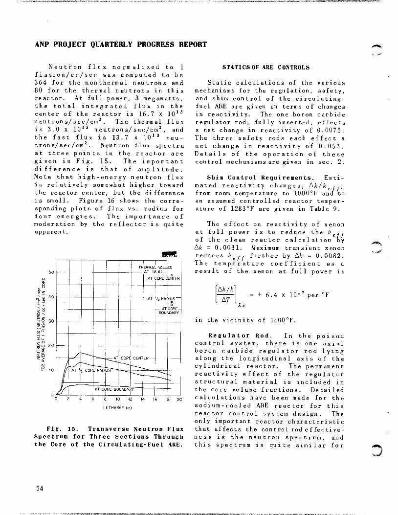
ANP PROJECT QUARTERLY PROGRESS REPORT
Neutron flux normalized to 1
fissi on/cc/sec was computed to be364 for the nonthermal neutrons and
80 for the thermal neutrons in this
reactor. At full power, 3 megawatts,the total integrated flux in thecenter of the reactor is 16.7 x 10¹³neutrons/sec/cm2. The thermal fluxis 3.0 X 10¹³ neutrons/sec/cm2, andthe fast flux is 13.7 x 10¹³ neutrons/sec/cm . Neutron flux spectraat three points in the reactor aregiven in Fig. 15. The importantdifference is that of amplitude.Note that high-energy neutron fluxis relatively somewhat higher towardthe reactor center, but the differenceis small. Figure 16 shows the corresponding plots of flux vs. radius forfour energies. The importance ofmoderation by the reflector is quiteapparent.
50
40
P. 9. 30
2°O UJ(E o
t <=> orUJ UJz >
20
Wmn!fm3z
THERMAL VALUESAT IRK: 1
AT ;orec ENTER
AT /z RAC IUS
©
BOUf^DARY
CORE CENT
-AT V2 CORE RAD
AT CC)RE BC UNDAF !Y
6 8 10 (2 14
LETHARGY (</)
18 20
Fig. 15. Transverse Neutron Flux
Spectrum for Three Sections Through
the Core of the Circulating-Fuel ARE.
54
STATICS OF ARE CONTROLS
Static calculations of the various
mechanisms for the regulation, safety,and shim control of the circulating-fuel ARE are given in terms of changesin reactivity. The one boron carbideregulator rod, fully inserted, effectsa net change in reactivity of 0.0075.The three safety rods each effect anet change in reactivity of 0.053.Details of the operation of thesecontrol mechanisms are given in sec. 2.
Shim Control Requirements. Esti
mated reactivity changes, Ak/k ,,,from room temperature to 1000°F and toan assumed controlled reactor temperature of 1283°F are given in Table 9.
The effect on reactivity of xenonat full power is to reduce the k rrof the clean reactor calculation byAk = 0.0031. Maximum transient xenonreduces kg , , further by Ak = 0.0082.The temperature coefficient as aresult of the xenon at full power is
Ak/k
AT= + 6.4 x 10- per
in the vicinity of 1400°F.
Regulator Rod. In the poisoncontrol system, there is one axialboron carbide regulator rod lyingalong the longitudinal axis of thecylindrical reactor. The permanentreactivity effect of the regulatorstructural material is included in
the core volume fractions. Detailed
calculations have been made for thesodium - cooled ARE reactor for this
reactor control system design. Theonly important reactor characteristicthat affects the control rod effectiveness is the neutron spectrum, andthis spectrum is quite similar for

•%,.,•
^"te**'
o 60<orUJ
50
o 45enC/J
40
o35
>-
k 30<x
h-
UJ OK_i 25
W IKQ_ 15
X
z
O K
h-3Ul
20
FOR PERIOD ENDING MARCH 10, 1952
DWG. 14433
—
,-" HtKMAL IMtUIRUIND —
^—\>
\N
•^
-
//
\
\
\
\
\
,^_---' 1 mev NEUT 30NS
\
\
500 ev NEUTRON1 1
1 I \
\j
I^1^1?^-2^- •f^CORE INTERFACE "
0.4 ev NEL)TR0N J__^ •> \\ j
'^JZ^\ !
4 6 8 ,0 12 14 16 18 20 22 24 26 28 30 32 34
SPACE POINT n {r = 2.062 n cm)
Radial Neutron-Flux Distribution in the Core of the Circulating-FuelFig. 16.
ARE.
the sodium-cooled reactor and thepresent ARE. Hence, the control rodeffect on reactivity is assumed tobe the same.
The net change in reactivity whenthe regulator rod is fully insertedis to be made 0.0075.
Safety Rods. Three safety rods areequally spaced on a 15-in. circlearound the reactor axis. The spacingis sufficiently large to reduce theshadowing effect of each rod on theothers to a relatively small value,and this effect is not considered.
These rods are 2-in. diameter cylindersof boron carbide with wall thicknessof 0.335 in., and a beryllium oxiderod is attached to the end of eachrod. The normal position of thesafety rods is out, so that berylliumoxide will be added to core materialwith a resulting decrease in theuranium requirement. The net changein kgff for each rod is thus the sumof two reactivity contributions:(1) from the removal of beryllium oxidemoderating material and (2) from theinsertion of a 2 -in . -diameter boroncarbide neutron-absorbing rod. Eachboron carbide rod is worth -5.3% in
55

en
EFFECT
Expansion of liquid fuel
Dimensional expansionwith constant material
Change of density ofInconel in core
Change of density ofreflector BeO
Change of cross sections
(except Xe) with reactortemperature
Change of Xe cross section
with reactor temperature
o
TABLE 9
Shim Control Requirements
ASSUMPTION
Volume expansion coefficients
per °F; fuel, 1.67 x 10"4(melting ignored), Inconel,0.20 x 10"4; difference,1.47 x 10_4
Radial expansion determined
by Inconel; axial, by BeO.
Linear expansion coefficientsper °F; Inconel, 6.7 x 10"6,BeO, 4.9 x lO'6, weightedaverage expansion coefficient:
linear 6. 1 x 10"6, volume18.3 x 10"6 per °F
Inconel volume expansion coefficient per °F, 20 x 10"6
Same as metal-cooled ARE
0.26 of decay products in the
core, remainder in external
EQUATION FOR (Ak/kgff)/AT
1.47 x 10"4Ak/k Ak/k
-+•
(An/m)v (Ao/p)coolant
6.1 x 10"Ak/k
(Afi/fl)
Ak/k18.3 x 10"
(Ao/p)mode rator
Ak/k20 x 10"6
(Ao/p)s tructure
Ak/k
°F
^/keff FOR CHANGEFROM 100
TO 1000 °F
-0.0554
0.0024
-0.0083
+0.0031
-0.0054
•0.0271
FROM 1000
TO 1283°F
-0.0174
0.00076
-0.0026
+0.00098
-0.0017
-0.0047
OF 1°F AT
OPER. TEMP.
-6.16 x 10"
2.67 x 10"
-0.92 x 10"
+3.5 x 10"
•5.7 x 10"6
-2 x 10" 6
+0.6 x 10"
>2"0
nnH
O
99
*090O«
n
99H
Total Ak/k -0.0907 -s-0.0247 1-7.2 x10
o o

v.,
FOR PERIOD ENDING MARCH 10, 19 52
Ak/k, and each beryllium oxide rod during the discussion was whetherin the same position is worth +0.16%. the existing beryllium oxide blocksThe Inconel around the boron carbide should be cut to accommodate therods is not an effective poison when larger fuel percentage. For thethe rods are inserted and results in 6.85% design, increaseof the potassiuma decrease in poison rod effect of fluoride mole fraction m the fuel0.21%. The net effect of insertion from 0 to 60% increased the criticalof the three safety rods is thus mass by 55%. For the 22.5% design,15.9% in kgff. This value is larger the corresponding increase was 105%.than that quoted for the metal- Since the use of potassium may becooled reactor because there is no necessary, the large sensitivity ofpoison NaK to displace. The maximum the 22.5% design to potassium workseffect of control rod motion is thus to the disadvantage of this design.16% in kefr, corresponding to about6 lb of uranium in the core. -phe power generation in a boron
carbide curtain on one end of a
SPECIFIC DESIGN PROBLEMS OF THE 3-megawatt ARE reactor was found tobe 0.53 watts/cm , 20% of which isdeveloped in the first 0.05 centi-
CIRCULATING-FUEL ARE
Dumping all the ARE fuel into aasingle tank does not result in
critical mass in the tank. The The problems of f uel - tube-wal 1assumptions pertinent to this con- corrosion may not be completelyelusion are given in Ref. 14; the solved by the time the ARE is beingmost important assumption is the built, and for this reason, as wellabsence of good moderators in or near as for reasons of fabrication, it isthe tank. highly desirable to use thick tube
, , walls. Under assumptions specifiedTwo ARE designs with volume frac- in the reference, (1') increasing the
tions of fuel in the core of 6.85 and tube waU thickness from 20 to 40 or22.5% were compared as to the sensi- 6Q milg increases the critical masstivity of their critical mass to the ^ ^ _g ^ u%> respec ti vely.addition of potassium (which has alarge absorption cross section) tothe fuel mixture/15' Of importance
meter.(16)
'^'c. B. Mills, The Power Generation in a(171 7. 77~, , „ , „ f B.C Curtain ARE on One End of the ARE No. 1(14,C. B. Mills, A Note on Fuel Dumping from "i
ARE No. 5. Y-F10-84, Jan. 18, 1952. Reactor, Y-F10-87, Jan. 21, 1952.(15)C. B. Mills, Effect of Potassium in the <l7)C. B. Mills, Effect of Structure on
Fuel-Coolant Solution in Two ARE Reactors. Criticality of the ARE of January 22, 1952.Y-F10-85, Jan. 21, 1952. Y-F10-89.
57

3

v..
5. CRITICAL EXPERIMENTS
A. D. Callihan, Physics Division
The group responsible for studies in the development of the directed preliminary reactor assemblies has cycle nuclear reactor for "r"?**continued investigations during the propulsion. Aloading chart of thispast quarter with the mockup of the assembly is shown in Fig. 17. DuringG-E direct-cycle reactor described in this quarter temperature effects onthe preceding report. <*> Relative reactivity have been studied and someevaluations, in terms of contributions comparisons have been made of theto reactivity, have been made of effect on reactivity of the berylliumseveral reflector modifications. Data reflector and of varying rel.tiveobtained several months ago from a thicknesses of stainless steel andcritical assembly of uranium and plastic substituted for the beryllium,graphite have been analyzed, and A control rod calibration was made,preliminary plans for experiments on and although the data obtained arethe liquid-fuel-coolant aircraft unique to the direct-cycle reactorreactor have been made. The data from they are of value for other types ofthe graphite assembly have been corre- reactors, since they indicate thelated with the theoretical calculations method and precision of evaluatingof the assembly. The correlation reactivity changes introduced bylacks precision but gives results that changes in reflector, structurala" at "a"' con8i8gtent with experi- elements, and other components.mental fact. _,
Control Rod Calibration. inechange in reactivity introduced by
i •> i Hi ctil a cement of each control rod hasDIRECT-CYCLE REACTOR^ L^ detTrrnined by two methods. In the„,.,,. first the "period" method, a measure-E. V. Haake and D V. P. Williams ^/n,'is made of the period of the
Physics Division supercritica1 system resulting fromW. G. Kennedy the insertion of a control rod, and
Pratt and Whitney Aircraft Division the corresponding change in reactivityis determined. In the second, the
Dunlap Scott "rod-drop" method, a safety rod isANP Division evaluated from the transient occurring
in the flux as the safety rod isThe preceding quarterly report' rapidly removed from the assembly,
described briefly an assembly of since each control rod is practicallyuranium, beryllium, methacrylate coaxial with a safety rod (Fig. 17),plastic, and stainless steel that was the over_aii value of correspondingdesigned to yield information of rodg ig taken to be equal,value to the General Electric Company
A comparison of the total rod<1>A D C.llih.n. -critical Experiments," calibrations obtained from the rod
Aircraft Nuclear Propulsion Project Quarterly drop method with the integrated ValueProgress Report for Period Ending December 10. period measurements is given'"'crvr;,/...!,,., .m. ........... ^ T.bl. v c„,r*,;..«„;.,be discussed in greater detail in a report that are expressed in "cents,' where 1UUis no* being written to the General Electric cent£. ("one dollar") is equivalent toCompany.
59

ANP PROJECT QUARTERLY PROGRESS REPORT
60
DWG. 14434
ABCDEFGH I JKLMNOPQRSTUVWX
Be REFLECTOR, JACKET 18 in. LONG, EACH HALF BACKED BY 6 in OFPDADUITr / r-MrN\i GRAPHITE (END
FUEL ELEMENT, EACH 18 in. LONG, EACH HALF BACKED BY 6 in OFGRAPHITE. TOP: 6 LAYERS OF STAINLESS STEEL, WITH 5 TO 10-milBY 3 in. URANIUM DISKS, HORIZONTAL. BOTTOM: 1in. OF PLEXIGLAS.
-STAINLESS STEEL, AIR, FUEL— PLEXIGLAS
LETTERS REPRESENT CONTROL ROD POSITIONS: NUMBERSSAFETY ROD POSITIONS.
Fig. 17. Loading Chart of Critical Assembly of Direct-Cycle Reactoi

0.00730 Ak/k. It is believed that theprecision of the rod-drop method is nogreater than ±2 cents, so the agreement in some cases is fortuitous.
TABLE 10
Comparison of Control Rod Calibrations
REACTIVITY CHANGE
PERIOD,
CONTROL CORRESPONDING INTEGRATED ROD DROP
ROD SAFETY ROD (cents) (cents)
A 5 18.2 16
B 6 15.9 16
C 1 15.9 18
D 3 18.3 18
Data obtained in the incrementalcalibration of control rod A by theperiod method are shown in Fig. 18,which gives the change in reactivityoccurring when the rod is withdrawnfrom the reactor.
8 12 16 20
ROD POSITION FROM MID-PLANE (in.)
Fig. 18. Reactivity as a Functionof Control Rod Position.
Temperature Effects. During theoperation of reactor assemblies anirreproducibility of varying degreehas been observed occasionally inday-to-day locations of control rods
FOR PERIOD ENDING MARCH 10, 1952
required for criticality under constant loading conditions. In the workreported here these variations exceededthe sensitivity required to detect thereactivity differences produced bysome structural changes under study.Investigations have indicated theprobable cause to be ambient temperature changes. The concomitant reactivity differences, from the reactivity at 72.9°F, are plotted asfunctions of temperature in Fig. 19.
0.9 t.O 1.1 1.2 1.3 1.4
MILLIVOLTS (IRON-CONSTANTAN)
0.00073
-0.OOO73
Fig. 19. Reactivity vs. Temperature.
Reflector Studies. An experimentwas initiated before the reactor was
in final form to compare the reactivityvalue of a reflector element with thatof a fuel element to ascertain themost satisfactory location of thesafety rod. A section of the berylliumreflector 22 in. long (one-half of the44-in. total reflector jacket length)was removed from positions M-21, V-ll,and W-ll (Fig. 17), and the resultingchange in reactivity was ascertainedby a calibrated control rod. Theresulting data (Table 11) give thereactivity change (with an estimatederror of ±1 cent) when a beryllium-filled tube is substituted for anair-filled tube.
61

ANP PROJECT QUARTERLY PROGRESS REPORT
TABLE 11
Reactivity Change Introduced bySubstituting Beryllium for Air
REACTIVITY CHANGE
TEST CELL (cents)
M-21 4.4
V-ll 10.9
V-ll and W-ll 27.5
In a second series of experiments,with final reactor geometry, theberyllium in a section 9 by 36 by 6 in.thick(3) was replaced by a type-310stainless steel section 9 by 36 by 3in. thick. This change was madeseparately at the side of the reactor,at the top, and at the bottom. Resultsgiving the change in reactivityeffected by the substitution and thechanges in location of the reflectoralterations are listed in Table 12(designations are the same as in Fig.17). The system was more reactivewith the beryllium reflector.
GRAPHITE REACTOR
E. L. Zimmerman, Physics Division
Limited effort has been directed tothe analysis of data obtained from auranium-graphite reactor and to correlation of the data with theory.This material will be presented whenthe analysis is complete. Such resultsas are now available are discussed ina subsequent paragraph on the "Correlation of Theory and Critical Experiments. "
CIRCULATING-FUEL REACTOR
Dunlap Scott, ANP Division
A preliminary assembly is to bemade of the projected aircraft propulsion reactor by using berylliumoxide as a moderator and reflector andmolten UF4-BeF2-NaF as a circulatingfuel and coolant. This assembly is tobe operated at room temperature andessentially zero power and will utilize
TABLE 12
Reactivity Change Effected by Substituting Plastic and Stainless Steelfor Beryllium in the Reflector
LOCATION
INITIAL POSITION
FINAL POSITIONREACTIVITY CHANGE
IN REACTOR PLASTIC IN STAINLESS STEEL IN (cents)
Side V,W-11, 12, 13 V-ll,12,13 W-ll, 12, 13 -56. 5
Top L,M,N-2,3 L.M.N-3 L.M.N-2 -41.3
Bottom L,M,N-21,22 L.M.N-21 L,M,N-22 -33.0
(3 )It must be noted that since the outside
dimensions of the aluminum tubing are 3 by 3 in.,the cross section of the units of the reflector(and the fuel) is 2 7/8 by 2 7/8 in., and theremainder is aluminum (wall) and air-filledspace. For convenience in discussion, the 3-in.dimension, and multiples thereof, will be used todesignate the reflector alterations. In thequantitive presentation of the data actual thick-nesses of the material will be stated, with theunderstanding that the voids are present.
62
beryllium oxide and packed-powder fuel;beryllium fluoride wi11 be omitted fromthe fuel for convenience in preparation.One possible experimental variable wi11be the uranium density of the fuel.In the first experiment the densitywill be that calculated for the molten
fluoride mixture for the ARE. Also
'^Sii^
.<^^|j

FOR PERIOD ENDING MARCH 10, 1952
the powder mixture will have the same integration of the age-d i ffus i or.uranium-sodium atomic ratio as the equation/4) a very definite attemptdesign fuel. However, it will probably has been made to determine whethernot be possible to achieve the over- these calculations can predict experi-all fuel density of the design fuel in mental results. Two separate barethis mockup. Design of fuel con- assemblies have been studied ,one with
nd control and safety devices beryllium as moderator and the othertamers a with graphite. Two assemblies areis under way. ° /. ,, .„
described in lable 16.
CORRELATION OF THEORY AND The results of the multigroupCRITICAL EXPERIMENTS calculations on these two reactors are
given in Table 14.D. K. Holmes, Physics Division
The values of kgJf listed in TableAn attempt has been made to de- 14 encourage the bel lef that the method
termine how closely theory can be made and the cross sections on which theto check with results from critical calculation is based are accurate;experiments. The several types of however, these results are somewhatresults that are subject to theoretical offset by the calculations of the agesanalysis include (1) criticality with 0f thermal neutrons in beryllium anda nonhydrogenous moderator and with a in graphite. Since both these calcu-hydrogenous moderator, (2) foil ex- lations involve the same multigroupposures (3) danger coefficients, (4) method and the same cross sections,rod sensitivity, and (5) the gap the correlation with experimental dataexperiment. would be expected to be similar to
that for the multiplication constants.Although criticality calculations Table 15 shows that whereas the calcu-
for both hydrogenous and nonhydrogenous lated value for graphite may bemoderated reactors are acceptably acceptable, the ca1cu1 ated age forconsistent, the results could be beryllium is not acceptable. Iheimproved in the case of a beryllium following possible explanations formoderator by the existence of better this discrepancy have been examined:cross-section data. Multigroup calcu-lations of hydrogen moderated reactors 1. Incorrect experimental valueyield high multiplication constants. for the age,Danger coefficient data provide afurther check of the multigroup method, 2. Incorrect values for the beryl-and the cross sections upon which these Hum scattering cross section,calculations are based agree reasonablywell, at least in the cases of iron 3. Neglect of p-scattenng inand nickel. Foil measurements also beryllium,show appreciable correlation withpredicted values. However, elementary The measurements of the age in beryl-theory on the loss of reactivity in Hum seem to be in good agreement,the gap experiment is consistently Changes in either the total scatteringabout 50% low. cross section or the p-scattering
contribution such as to give theCriticality with Nonhydrogenous correct value for the age, when
Moderators. Since considerable efforthas been devoted to Setting Up the (4)M j Nielsen, Bare Pile Adjoint Solution,"multigroup" technique for numerical Y-F10-18. Oct. 27, 1950.
63

ANP PROJECT QUARTERLY PROGRESS REPORT
applied to the criticality calculations,lead to values for k of around0.90. U
An additional complication isintroduced by the possibility of theexistence of a significant crosssection for the (n,2n) reaction in
beryllium/5) Various experimentalestimates for this cross section maylead to increases of as much as 20%in the calculated kg , for assembly 1.At present the best approach to matching the calculations with experimentaldata is probably that of allowing somep-scattering to raise the calculated
TABLE 13
Experimental Data on Critical Assemblies 1 and 4
Critical dimensions
Volume fractions of constituent material:Fuel (93.4% U23S)
Beryl 1ium
Carbon
Stainless steel
Aluminum
Total mass 93. 4% U235
ASSEMBLY 1
21 x 21 x 23.22 in.
0.00658
0.90202
0.000826
0.03004
19.36 kg
ASSEMBLY 4
51 x 51 x 44.Ill in.
0.0015032
0.88916
0.0003127
0.06073
57.092*
to tSio,ut.iigd.reof'th.he..t.°::blv""Ac0tu.fni WtHhCh W°Uld ^ reS6nt ^ tHe lDading hBd b"" —ied """or,.!,negligible for purposes of calculation tin, 11 "^ * ?' ""' ^ *he diff"e"<- - considered to beover-al! di..n.?on'of 51V^^^.S o^dl^^ ^ "»{ 'J.^ .'£.<», -. - ' <H
TABLE 14
Calculated Results for CriticalAssemblies 1 and 4
ASSEMBLY 1
k fteft 0 98*
Median energy forfission
1 1 ev
Fraction of fissionsthat are thermal
0. 107
ASSEMBLY 4
0.9912*
0. 15
0.274
Th, figures are based on uranium crosssections corrected for se1f-shie1 ding owing tofuel lumping (10-mil disks). The removal of theself-shielding factors (calculations may be opento question) made only a 1 to 2% difference in
64
TABLE 15
Comparison of Experimental andCalculated Values of the Ages ofThermal Neutrons in Beryllium
and Graphite
BERYLLIUM
(cm2)GRAPHITE
(cm2)
Measured age
Calculated age
93
69
350
391
W. K. Ergen, On the (n,2n) Reaction inBeryllium with Neutrons of a Poloniam-BeryI IiumSource, Y-F20-12, Apr. 30, 1951.
haikW

FOR PERIOD ENDING MARCH 10, 1952
age and also some (n,2n) cross section AB. Ac. A„. respectively, the follow-to bring the kgff back to unity. In ing proportionalities are obtained,the absence of reliable experimentaldata on both points, such calculations <?0 ,/FWFwould be purely speculative. In any AR ~ / L/U) <pKB.)dtcase, it seems fair to conclude that J£tkthe method of calculation gives resultsthat are at least consistent withexperimental fact. ^ ^ T£o ^(£) £/(E) ^(£)d£
Criticality with Hydrogenous thModerators. A modified form of themultigroup method has been used to „calculate the multiplication con- Aci ^ I fci^E^ ^(E) <piE)dEstants for four critical assemblies Jgfhconsisting of either bare or reflectedcores of solutions of uranium hexa- wherefluoride in water. An extra term is £ = ^^ high neutron energy,added to the usual age-diffusion 0 1Q Meyequation to take account of therelatively large energy losses of the = thermal energyjneutrons because of scattering in thhydrogenous materials. Since the .... „„eoreflectors, when used, were es- L(E) = macroscopic fission crosssentially infinite and of water, a section of the fuel disks,simple, reflector-saving correction to , .. nthe bare calculation was used. The <p{E) = neutron flux as a functionresults'6' gave effective multipli- of energy,cation constants ranging from 0.97 to0.988 for the critical assemblies. ^ ^ (£) are the frac.Since the reactors ranged from 41.5 to ^.^ Cf ^ inc^dent neutrons of94% thermal and a simple age -di itusion, en £ that reach the fuel disk,multigroup calculation gave effective ^^ expressions it maV be seenmultiplication constants about 20% too ^^ ^ extent to which a calculationhigh, it may be expected that the ^^ activities checks experimentalmethod of calculation will give results i s some measure of the accuracyacceptable results, in general, tor ^ ^ calculation of the flux as ahydrogenous reactors. function of energy. For purposes of
•ui .. rnmnarison ratios of activations areFoil Exposures. It is possible to comparison ^ ^^calculate the activity of an aluminu, used 1 e ^ ^ expe^mentcatcher foil piaced against a fuel It I assembly 4, the graphitedisk, either bare, cadmium covered or ^*« The variation of thecadmium-indium covered if the neutron «bl *' reactor must beflux in the region and the uranium and ratios uv ,,ilux in tne regio 0„r;nnCi are attributed to the loading in assemblycadmium capture cross sections are continuing uniformly to theknown as functions of energy. By 4 J ^ ^ Quterdenoting the activations bare, cadmium edgo y ^_j .^ ^^covered, and cadmium-mdium covered by ^^ \. gher fraction o£ the neutron
flux is thermal near the edge of the(6)C. B. Mills, Water Moderated Reactors, reactor The calculation represents
Y-F10-78, Jan. 7, 1.952.
65

ANP PROJECT QUARTERLY PROGRESS REPORT
an average over the entire reactor.The calculated values reported inTable 16 do not take into account therelative depression of the low energyend of the flux spectrum near the foilupon introduction of the cadmium.Including this effect would tend toraise both calculated values.
TABLE 16
Experimental and Calculated Values forthe Cadmium and Cadmium-Indium Ratios
Cadmium ratio
Cadmium-indium
A
ratio =-
B
CI
EXPERIMENTAL
CENTER OF
ASSEMBLY
2.11
3.40
OUTSIDE
EDGE OF
ASSEMBLY
2.60
3.90
CALCULATED
2.72
2.98
uniformly over the volume of thereactor, whereas in the experiment thematerial is concentrated at the centerof the assembly, the calculatedresults are multiplied by (7f/2)3 toproperly weight the importance of thecenter of the reactor.] The new k ,,
, e f fis then compared with the old oneobtained before the introduction ofnew material. Since the volumefractions of the added materials arerelatively small, this method involvestaking small differences of largenumbers; however, it is felt that thenumerical methods used are quiteadequate for this case, and the methodhas the advantage of including thescattering cross section and the £ forthe added material as well as itsabsorption cross section. The secondmethod is a perturbation techniquethat involves the calculation of an"importance" function^1) (of energy)for the assembly. The perturbationmethod allows the material to beplaced directly at the center of thereactor but, as used for the dangercoefficient calculations, takes intoaccount only the absorption crosssection of the added material; thusany gain in moderation over the voidis not included in the perturbationmethod. In Table 17 the total lossln keff uP°n introduction of a blockof the material of the size listedinto assembly 4 is given.
An additional effect owing to thelumping of the added material, whichwould reduce the effective absorptioncross section, was not included in thecalculation; such an effect wouldreduce the magnitudes of the numberscalculated.
Danger Coefficients. A furthercheck of the multigroup method and thecross sections on which calculationsare based is available in the dangercoefficient measurements. Experimentally, the measurement consists ofdetermining the loss in reactivitywhen a block of some material isplaced in the center of the assembly.(The comparison is with a void of thesame size and at the same position asthe block of material; the experimentswere performed on assembly 4.) Thereare two methods of calculation thatmaybe used to check these experiments.In the "difference method," the reactivity i s recomputed for the assemblyusing the multigroup method with theproper additional amount of theparticular material added to theassembly. [Since the material is, bythis procedure, essentially spread
Rod Sensitivity. The control rodsfor assembly 4 were typical sectionsabout 3 by 3 in. in cross section andextended from the center to the edgeof the assembly. An experiment ,whichis of interest from a theoretical point
66

N»iV,^
FOR PERIOD ENDING MARCH 10, 1952
TABLE 17
Experimental and Calculated Values for the Total Loss in kgff upon Introductionof Various Materials into Assembly 4
Ak ,, x ioeff .
CALCULATED
MATERIAL
SIZE OF BLOCK
(in.) EXPERIMENTAL DIFFERENCE PERTURBATION
Sodium
Iron
Iron
Nickel
Molybdenum
3x3x1
3x3x1
3 x 3 x M
3 x 3 x lA
3 x 3 x lA
0.066
1.44
0.450
0.657
1.31
0.002
1.42
0.368
0.700
0.600
2.23
0.560
0.960
of view, is the measurement of theincremental sensitivity of such a rodas a function of position in theassembly, i.e.,
Akeff
k ,, AxI eff
evaluated when the control rod iswithdrawn (from the center) a distancex. In the relatively simple case of avery thin poison rod (which leavesbehind a negligible void as it iswithdrawn) the data for assembly 4fitted the theoretically expectedimportance function, i.e.,
1 Afeeff ~ cos-* yx
I*.// Ax-*thin poison rod
where x is measured from the center ofthe reactor, and y = rr/L, where L isthe length of the reactor. However,the "typical-element" control rod,which does leave a 3 by 3 in. void
channel behind as it is withdrawn,showed an entirely different behavior.The sensitivity was fairly constant asa function of x until the rod had beenwithdrawn somewhat over three-quartersof the total rod length, at whichpoint the sensitivity rose to a maximum(about 20% above its value at thecenter of the assembly) and then fellrapidly as the edge of the reactor wasapproached.
It seems fairly certain that theremoval of a block of moderator ofwidth Ax at a point x in the reactor(leaving a thin void section behind)should give a change in keff thatvaries again as cos2 yx; thus thepeculiar behavior of the rod sensitivityseems most likely to be the result ofthe void channel, which is of length(L/2) - x when the rod has been withdrawn a distance x. Thus it ispossible that a term provided by thetransport of neutrons along the channelfrom near the center of the reactor toa region of much lower importance nearthe outside might account for the
67

ANP PROJECT QUARTERLY PROGRESS REPORT
experimental result. A typical formfor the theoretical estimate of thise ffect i s :
has the values for the void effectgiven by the integration above, and tochoose A and B so that an acceptable
1 Akeff
effAx
d
dx «/q«/n «/nIix' - x") Pix' - x") dx1 dx"
void
where Pix' - x" ) is the probabilitythat a neutron will make a flightthrough the void, leave the channelwalls at x', and re-enter at x". Thisterm will depend upon the flux at x'and the solid angle subtended at x'by a small area at x" . Hx' - x") isthe change in importance of a neutronwhile being transported from x' to x".Since the integral is over all valuesof x' and x", account is taken of thegam in importance owing to transporttoward the center of the reactor, butthis will be smaller than the loss ofimportance since the flux falls offfrom the center as cos yx. Numericalevaluation of the integrals shownindicates that the void contributionto the rod sensitivity rises from zeroat the center of the assembly to amaximum near the three-quarter pointand then falls off rapidly. It ispossible to write
k Ax
wnere
total
_1_ A£Fa*" + B
moderator
^ Afe~k Ax"
void
fit to the experimental dataobta ined.
1 s
Gap Experiment. With calibratedcontrol rods it is possible to measurethe loss in reactivity upon separatingthe two halves of the reactor at thecenter plane. Such an experiment wasperformed on assembly 4 with separations up to 0.3 in. and losses inreactivity up to about 0.005. A calculation has been made by using themultigroup method and allowing anapparent absorption cross section ateach lethargy corresponding to theprobability for loss of neutrons fromthe gap [with a weighting factor ofi-rr/2)3 to account for the fact thatthe losses are actually from thecenter of the reactor]. The leakagelosses from the gap were calculated byusing the results given in CP-3443.(7>The calculated losses in k f, areuniformly about 50% lower than theexperimental results. However, sincethe maximum separation of halves isonly 0.3 in., whereas the dimension ofa face of the reactor is 51 in., theentire experiment is in the range of"small gap" for which the results ofCP-3443 are known to underestimate theleakage from the gap. An improvementof the method of CP-3443 has been made,and the losses are now being recalculated on the new basis.
1^ AkF Ax" cos yx
(7)
J. E .-._,,Reactivity. CP-3 44 3, Feb 7^2 0," 19 46^
M. G. Goldberger, M. L. Goldberger. andWUkins, Jr., The Effect of Gaps on Pilemoderator
68

Part II
SHIELDING RESEARCH

fe^i^ie-'siStityai&sfe'E. *' (

SUMMARY AND INTRODUCTION
E. P. Blizard, Physics Division
The mockup of the divided shield is possible full-scale (but not full-now being measured in the Bulk Shield- intensity) measurements of divideding Facility (sec. 6). The angular shields has been completed (sec. 8).and energy-dependent gamma-ray measure- The resulting configuration, basicallyments that have been obtained are a 300-ft tower with a 100-ft crossgratifyingly detailed. It is not member for the reactor and crew shield,certain that the neutron spectral and meets all requirements regardingangular distributions will be as freedom from spuriously scatteredamenable to measurements; the in- radiation and flexibility. It l s
struments for these measurements are estimated that this facility willstill being developed. cost about two million dollars and
Research on ducts has included that it will be completed in thedetailed measurement of the effect of middle of 1953.duct geometry on neutron transmission,as well as the experimental corrobo- ajj-^- iT-oi-i^r. t • i • r • j .. l r Additional cross-section measure-ration of a simplified theory of , , , ,
. . . , ' ments have been obtained on the 5-Mevneutron transmission in ducts (sec. 7). v„„ -j r ts j ^u • r j-, • ,T. .. l .. L , Van de Graaff and the time - of - f 11 ehtThe agreement between theory and no„ ».,.„„ t • e
' neutron spectrometer for use in reactorexperiment for duct transmission is
,W within a factor of 2 for attenuations6
cross-section measurements has beencompleted (sec. 9). The spectrometer
as high as 10 . Duct parameters in- u u *. 11 ^ ,'„„ ,. • * j • i » . • .. , , nas been installed and the countingvestigated include diameter, length, t .. • • . , , , ,„„
. , r . . ' 6 ' rates optimized and tested on the LITR.and angles of a single bend. ,, <. , ,
Measurements of the total cross sectionA comprehensive design of the Tower of iron on the 5-Mev accelerator extend
Shielding Facility, which will make from 0.7 to 3.6 Mev.
71


BULK SHIELDING REACTOR
J. L. Meem H. E. Hungerford
R. G. Cochran E. B. Johnson
M. P. Haydon J. K. Leslie
K. M. Henry F. C. Maienschein
L. B. Holland G. M. McCammon
T. N. R oseberr y
Physics Division
The divided shield mockup, supplied measurements are being taken along theby the General Electric Company, has center line out from the front face ofbeen installed in the Bulk Shielding the reactor, as follows:Facility. For these measurements thereactor was reloaded to completely ^ Center line measurements offill the lattice of the reactor and thermal-neutron flux, fast-neutronto minimize the effect of the borated dosage, and gamma-ray dosage, such aswater. The gamma-ray spectroscopy is were made on the unit-shield mockup,well under way, but instrumentationrequired for the neutron spectroscopy ^ Energy and angular distributionwill not be completed until this of gamma raySjsummer.
3. Energy and angular distributionMOCKUP OF THE DIVIDED SHIELD of neutrons.
The divided shield mockup consistsof a tank cylindrical on the sides and Unit-shield measurements will pro-roughly hemispherical in front (Fig. vide a temporary estimate of measure-20). A vertical slot that barely lent l.and measurement 2, the gamma-allows clearance for the reactor is ray spectroscopy, is well under waycut along the length of the cylindrical Assuming 140 cm to be a typical shieldsection so that the reactor and its thickness, measurements have been madesupporting bridge may be moved back with the spectrometer* > at various
r r. u • 7,4 r i'„j,;, l »^r angles with respect to the center lineout of the shield. Cylindrical air a 6 v• •, . j -a ,.0^™ r,f (see Fie. 20). The results have beenvoids on the sides provide a region of \see ,g , , ... , • (21 a
s - „j „ommo described by Maienschein^' and areno attenuation for neutrons and gamma a ' or.=„j0rays. This has the effect of simulat- shown in Fig. 21. These data supersedeing a reactor 4 ft in diameter and the preliminary spectra data previous lyextending out to the walls of the air reported,voids. Mounting brackets are providedto hold two, large, roughly hemispheri,,,,'• i 'u *- „ k„ :„„,all0J (1)F. C. Maienschein, Multiple-Crystal Goinma-cal, lead dishes that can be installed Ray Spectrometer, oRNL-1142 (in press).
to mockup the lead shadow shield. . .„, ,. , ». u • «J F. C. Maienschein, Coma-Raj SpectralThese lead dishes are not being used WeasureKents vith the Divided shield Mock-up,for the present experiments. Part i, ORNL CF-52-3-1, Mar. 3, 1952.
Figure 5.1, "Preliminary Gamma-Ray SpectrumFor the experiments now under way at 130 cm from the Water-Reflected Reactor,"
r , Aircraft Nuclear Propulsion Project Quarterlythe shield has been filled With borated Progress Report for Period Ending September 10,water (0.4 wt % boron), and all 1951, ORNL-1154, P. 85.
73

-a
BORATEDWATER-
SECTION A-A
-PROPOSED LEADSHADOW SHIELDS
Fig. 20. Relative Position of Reactor, Divided Shield, and Gamma-Ray Spectrometer in Bulk ShieldingFacility.
O
>
ns
IB
§M
H
Oe•so
"038O«
a>
99m
s90H
)

FOR PERIOD ENDING MARCH 10, 1952
4 6 8 10
GAMMA-RAY ENERGY (Mev)
DWG. 14235
12 14
Fig. 21. Gamma-Ray Spectra at 130 cm from the Water-Reflected Reactor.
75

ANP PROJECT QUARTERLY PROGRESS REPORT
Measurements are now being made atvarious other distances from thereactor. The reactor will then bemoved out of the shield into the openwater, and a few of the measurementswill be repeated for comparison withthe spectra in the borated-watershield. Finally, an attempt will bemade to measure the spectrum of gammarays emerging from the face of thereactor.
The third measurement, the energyand angular distribution of theneutrons, will be undertaken as soon
as the necessary instruments have beendeveloped, which now appears likely tobe some time this summer.
REACTOR CALIBRATION
For the divided-shield experimentsthe reactor was loaded so as to completely fill the lattice when rolledinto the shield as shown in Fig. 20.Furthermore, since the shield contained borated water and duplicatemeasurements were to be made with the
reactor in the open water behind theshield, the reactor was loaded so asto minimize the effect of the borated
76
•"jU»*JW;*i*m(ta!Wf'iiif.w..A;i!*-i, tiimM:
water and was surrounded on four sides
with beryllium oxide reflector as shownin Fig. 22. Fuel elements were addedin the interior of the lattice untilcriticality was reached with 3.1 kg of
235U The complete interior could notbe filled, but two positions (44 and46) had extra beryllium oxide elementsand two positions (43 and 47) wereleft filled with water. Repeating thecritical experiment in the open waternecessitated a slight rearrangement ofthe extra beryllium oxide elements,which amounted to exchanging thepositions of the extra beryllium oxideelements (44 and 46 above) with thatof the water (43 and 47). The finalassembly required about 30 g less offuel.
The power distribution of the twocritical assemblies is being measuredwith gold foils, following the methodof Meem and Johnson.(4) All data onthe divided-shield measurements willbe normalized to 1 watt using thesepower calibrations.
(4)J. L. Meem and E. B. Johnson, De termination
of the Power of the Shield-Testing Reactor - J.Neutron Flux Measurements in the Water-ReflectedReactor, ORNL-1027, Aug. 13, 1951.
^m^%

"w
SAFETY RODS
REACTOR GRID PLATE
pa
CONTROL ROD
FOR PERIOD ENDING MARCH 10, 1952
DWG.14437
BeO REFLECTOR
Fig. 22. Fuel Assembly Arrangement of Bulk Shielding Facility Reactor.
77

•*<#'

DUCT TESTS
C. E. Clifford
M. Hull ingsA.
F. Muckenthaler
L. Abbott
Simon
Physics Division
Duct work has been directed toward
obtaining further experimental corroboration of the simplified theoryof neutron transmission throughcylindrical, air-filled ducts inwater. The effects of further vari
ations in duct diameters, lengths, andangles of a single bend (with straightsections of equal length) on neutrontransmission through the duct havebeen measured in the Thermal Column
Facility. In addition to the abovevariations, measurements have alsobeen made to predict the effectivesource area that contributes to theradiation reaching the exit of asingle duct. An increase of a factorof 6 in the calculated source strengthresulted when the source was increasedfrom an area equal to that of theduct mouth to a much larger area.This was measured for only one ductsize (3 in. ID) and is reported toindicate the order of magnitude ofthe effect. This is, of course, veryimportant for extrapolating thesingle-duct data to a reactor designin which an array is used.
The agreement with the theory hasremained good in that the dose canbe predicted for a given duct geometrywithin a factor of 2 when the geometrical attenuation of the duct is
as high as 10"6. A report of allthe experimental and theoretical workon ducts is essentially complete andwill be issued during the next quarter.
THEORETICAL TREATMENT OF DUCT
TRANSMISSION
The generalized equation used topredict a measured dose at the end of
duct can be written as follows:
D = n„
( 2^TTa
2 ~a
. 4 8lr2.
\a2
ka2
l22 sin 6l
8Z2,. sin 6m + 1 m
(i)
D = relative dose (thermal-neutron
flux),
nQ - relative source strength perunit area,
a - diameter of duct,
I - length of mth straight section,
A. - experimentally determinedconstant, including neutronalbedo, etc.,
6 = angle between mth and mth + 1m ^
straight section.
For the special case of equal-length straight sections with bendsof equal angles3the equation becomes:
rra.2 ~1
8Z2
ka2
8V sin
m. 1
(2)
where m is the number of straightsections. This case gives minimumtransmission for a given center linelength. It should be noted that theequations are not valid for anglesof bend that are so small that neutrons
can pass directly through the duct
79

ANP PROJECT QUARTERLY PROGRESS REPORT ^
without a wall collision. The formula hose (60 in. in length, 1/4-in. walls)becomes increasingly more accurate as with single bends of 0 to 90 degreesthe angle of bend approaches 90 degrees. was measured with both the full
rectangular source and a 3-in.-diametercircular source. The ducts weresealed with 1 1/2-in. rubber plugs to
MEASUREMENT OF AIR-FILLED DUCTS give an actual air column of 57 inches.IN WATER The two straight sections shortened
as the angle of bend increased, sinceFor correlation with the above the hose was always bent with a 12-in.
theory, measurements were made with radius of curvature. For each anglevarious configurations of air-filled, the straight sections were of equalcylindrical ducts in the Thermal length.Column water tank, including straightducts and ducts with single bends up The smallest angle of bend wasto 90 degrees. The source areas were equivalent to a displacement of thealso varied. The measured results center of the duct by one diameterhave been compared with the preceding to prevent neutrons from reachingtheory and are within a factor of 2 the counter without having made atfor a given duct geometry. least one collisionor having penetrated
the surrounding water. Center lineStraight Ducts. One end of the and traverse measurements for the full
duct was placed against a fission source are shown in Figs. 25 and 26. ^^source (uranium slugs) in the Thermal Center line measurements were also ^JColumn water tank, and the counter made on a 4 1/4 - in. -diameter ductwas located in the various slots of with aluminum walls,the counter holder at the other end
of the duct. (These ducts had 1/4-in. Comparison with Theory. In orderlucite walls and were closed at each to compare the measured results withend with a 1/4-in. lucite disk.) The the predictions of Eq. 1 or Eq. 2, anfission-source box included a movable effective source strength must becadmium shutter to cover the source determined. To simplify the calcu-for background measurements. lations and also to give some idea
of the change in duct transmissionMeasurements were taken on all with energy, the effective source
straight-duct configurations with the strengths have been arbitrarily definedfull source, which consisted of 24 as the relative thermal flux (thenatural uranium slugs, 1 1/8 by 4 1/8 response of a specified counter atin., in a rectangular array (9.3 by 10, 20, and 30 cm of water from the12.4 in.). Additional measurements end of the duct) multiplied by thewere made on the 6-in.-ID ducts using geometrical attenuation of the duct,a 6-in.-diameter circular source by that is, D/nQ from Eq. 1 or Eq. 2.placing a cadmium shutter with a It was assumed that the counter was6-in.-diameter hole beneath the slugs. large enough to give a reading p ro-Typical curves for the neutron trans- portional to the integral of the fluxmission, as measured along the center leaving the duct. This can be shownline of the 6-in.-ID ducts, are given to be nearly correct by a comparisonin Fig. 23, and traverse measurements of integrals under the traverses withare shown in Fig. 24. the center line readings for various
ducts. If the formula is correct, "' "3Ducts with Bends. The transmission nQ should be a function only of the
of neutrons through a flexible rubber distance from the duct end, provided,
80
Ntf**'

"w
V
FOR PERIOD ENDING MARCH 10, 1952
1068
6
DWG. 14438
1058
6
1 1 1 1 1 11 1 ' I 1 1DUCTS: 6 in. ID, PLASTIC WALLS
v Z. =24in.A Z. = 36 in.
© Z. = 48 in.
El PURE WAT FR FOR / = 24 in.
<SOURCE: RECTANGULAR.9.3 X 12.4 in.COUNTER AT x = <t
Q—-
\
\5
^—V 4A
Av
k—\
TO
&
H
3Oo
UJ
en
2O0_iT)
UJ
CC
OCUJ
1048
6
3
o 2
ro
Ll
m 103
i 8io 6(M
uT 4cc
<n
(f> 2UJ
or
Q.
i 102o 8
100 10 20 30 40 50
7, COUNTER DISTANCE FROM END OF DUCT (cm)
Fig. 23. Center Line Measurements of Neutron Trans-mission Through Cylindrical Ducts in Water.
81

ANP PROJECT QUARTERLY PROGRESS REPORT
3
2
DWG. 14439
1058
|
\\\
_^*T-~^
r *
DUC TS: 6 in. ID, PLAS TIC W ALLS—V
© L = 24 in.
A L = 36 in.
v) Z. = 48 in.
V PURE WATER FOR L = 24 in. —\—
- SOURCE • RECTANGULAR 9 3 X 1? 4 in \r.nilMTFR AT 7 - fi 3 r.m
\J
\v
1 2oo
UJ
en
zoo.(/}
UJ
cr
a:uj
i-
Oo
rO
U_
GO
IT)
CJ
UJ
o:3
(/)
(/)
UJ
£t0_
I
1048
6
1038
6
1028
6
10-30
Fig. 24.
Ducts.
82
-20 -10 0 10 20 30
*,COUNTER DISTANCE FROM DUCT CENTER LINE (cm)
40
Traverse Measurements of Neutrons in Water Beyond Cylindrical
3
w

FOR PERIOD ENDING MARCH 10, 1952
1058
6
1048
6
c
E
c
o
1038
6
4
DWG. 14440
LUcn
zoa(ftUJ
or
ocuii-
Oo
(7\
DUCT: 3-in.lDx 60 in.; RUBBER WALLS; _<1/ ;« dmdqcd di i\n im cupu run —
© STRAIGHT
A 13.5 deg. BEND
Q 33.25 deg. BEND -H 46.5 deg. BEND
V 60.6 deg. BEND
v a yu deg. BEND _\
\ s0URCE : RECTANGULAR,9.3 x 12.4 m._r.nilNTFR ATr:? _
\ i\i
\A\ \ /a
\/
_wy)
\^\\ \
\
/\ \ \
\\ \
vVvl A
102
8
6
10
8
6
10 20 30 40 50z, COUNTER DISTANCE FROM END OF DUCT (cm
60
Fig. 25. Center Line Measurements of Neutron Transmission in Water Through Cylindrical Ducts with Variable
Bends.
83

ANP PROJECT QUARTERLY PROGRESS REPORT
84
1058
6
1048
6
£ 2</>
c
3
S io3
Z 8£ 6oa. 4inUJ
a:
UJ <i
8l02J° 8m '. 6
10
8
6
DWG. 14441
I/TV*-
x$
©©
y / ZXzS><?/ s s S—-\
)~//
f (
/ N\ \
Vz ia
/ wc /
\ \
1 / \ \
Vi Wjs / \f\
M / p % \
n UCT: 3 in. ID, X 60 in.,RUBBER WALLS ;1V2-in.RUBBER PLUG IN EACH END
© STRAIGHT
A 13.5 deg.BEND
^ 33.25 deg. BEND0 46.5 deg. BEND
V 60.6 deg.BENDOURCE : RECTANGULAR, 9.3 X 12.4
\\\\
\ v\ 1
\1-|
u
S n.
uuumen mi ^ - 0.3 I;m
-30 -20 -10 0 10 20
*,COUNTER DISTANCE FROM DUCT CENTERLINE (cm)30
Fig. 26. Traverse Measurements of Neutrons in Water Beyond
Cylindrical Ducts with Variable Bends.
fl«™»l%!..
**%,w

V...
of course, that the source is eitherthe same size as the duct mouth or essentially infinite in extent. Thatthe formula is accurate to within afactor of 2 may be seen in Table 18,for straight ducts, and Table 19, forducts with bends. These tablessummarize the calculations of nQ foreach duct geometry measured to date.The measurements will continue on aseries of 4 1/4-in. cylindrical ducts.
The effective source strength, nQ ,is plotted as a function of theequivalent centimeters of water betweenthe counter and the end of the duct
FOR PERIOD ENDING MARCH 10, 1952
in Fig. 27. The lower group appliesto the 3-in. duct with the 1 l/2-in.rubber plug adjacent to the source,whereas the upper group representsdata from ducts that did not haverubber plugs. The difference is notsimply ascribable to the attenuationof the plug since this correction hadalready been applied. No satisfactoryexplanation has yet been obtained.Further work is being done to clarifythe above enigma. The increase innn upon increasing the source sizebeyond the area of the duct mouth isshown in Fig. 28, which also showsangular correlation.
TABLE 18
Comparison of Calculated Effective Source Strength for Straight,Cylindrical Ducts
Low-pressure, 25-in., BF3 counter
t 10, 20, and 30 cm of water from end of ductCalculated from counter responses
DUCT(a)LENGTH
(in.)
EFFECTIVE SOURCE STRENGTHDUCT
SOURCE
nn (neutrons/cm /sec)DIAMETER
(in. )10 cm 20 cm 30 c m
6 24
36
48
Full(b)Full
Full
1.05 x 1032.64 x 1027.25 x 102
1.29 x 1021.14 x 1021.08 x 102
1 . 58
1. 51
1. 59
X 10
x 10
x 10
6 24
36
48
6 IB.
6 in.
6 in.
4.1 x 1023.43 x 1023.04 x 102
5.62 x 10
5. 28 x 10
4.91 x 10
7. 96
7. 92
7. 96
8 24
36
48
Full
Full
Full
7.4 x 1027.99 x 1027.1 x 102
9.99 x 10
1.04 x 1029.6 2 x 10
1. 33
1. 33
1. 33
x 10
x 10
x 10
'"'includes plastic ends.
("24 uranxun, slugs, 1 1/8 by 4 1/8 i... in rectangular array, 9.3 by 12.4 inches.
'c'6-in.-diameter circular source.
85

ANP PROJECT QUARTERLY PROGRESS REPORT
TABLE 19
Comparison of Calculated Effective Source Strength for Bent,Cylindrical Ducts
Low-pressure, 25-in., BF3 counterCalculated from counter responses at 10, 20, and 30 cm of water from end of duct<°>
DUCT
DUCT CENTER LINE ONE-BEND EFFECTIVE SOURCE STRENGTHDIAMETER
(in.)LENGTH
(in.) SOURCE
ANGLE
(deg.)
n0 (neutrons/cm /sec)
10 cm 20 cm 30 cm
3 57 Full<b> 0 6.7 x 10² 9.18 x 10 1.29 x 10Full 13.5 1.32 x 10³ 1.87 x 10² 3.57 x 10Full 33.25 1.37 x 10³ 1.22 x 10² 1.68 x 10Full 46.5 1.26 x 10³ 9.1 x 10 9.0Full 60.6 1.45 x 10³ 9.25 x 10 9.2Full 90 6. 6 x 10² 6.1 x 10
3 57 3 i„.<e> 0 1. 1 x 10² 1. 64 x 10 4.223 in. 13.5 1.71 x 10² 2. 60 x 10 6.053 in. 33.25 1.57 x 10² 2. 14 x 10 3.29
4.25 40 3 in. 0 2.68 x 10² 4.4 x 10 6.95
— L
3 in. 90 3.99 x 10²— .—L
3.92 x 10 4.31
86
(a)Includes rubber plugs on all 3-in. ducts.
24 uranium slugs, 1 1/8 by 4 1/8 in., in rectangular arra
3-in. -diameter circular source.
(b)
(c)y, 9.3 by 12.4 in.
in*?
•*mt^

V...
104
8
6
4
103
8
<" 6
FOR PERIOD ENDING MARCH 10, 1952
DWG. 14442
X X
6-in.-ID DUCT, 6-in.-dia. CIRCULAR SOURCEO 24 in.
A 36 in.
D 48 in.
- 3-in-IDx 57-in.DUCT.3-in.-dia. CIRCULAR SOURCEX STRAIGHT
V 13.5 deg. BEND
X 33.25 deg. BEND
41/4-in.-ID x40-in. DUCT, 3-in.-dia. CIRCULARSOURCE
o STRAIGHT
a 90 deg. BEND-o-
10 20U EQUIVALENT CENTIMETERS OF WATER FROM END OF DUCT
Fig. 27. Comparison of Relative Source Strengths (nQ) fromVarious Ducts. Source area equal to duct mouth area.
87

ANP PROJECT QUARTERLY PROGRESS REPORT
88
20 30EQUIVALENT CENTIMETERS OF WATER FROM END OF DUCT
Fig. 28. Comparison of Relati ve Source Strengths (n ) fromVarious Geometries of the 3-in. Duct.
-*w«n*f*^*»ia»aii*'w«..*.>*
W

V
8. TOWER SHIELDING FACILITY
J. L. Meem
A. Simon
vision
measure the ground scattering. Thisis a very welcome potentiality sincethe calculations of this effect maynot be accurate and it can thus be assuredthat the divided-shield measurementsdo not incorporate an unknown spuriouscomponent. In addition, it will bepossible to estimate the added crewexposure from ground scattering thatwill be incurred on take-off andlanding.
It will be possible to mount largepieces of structural material (e.g.,aluminum) at various locations aroundthe reactor or crew shields to simulateairplane structure. Thus the radiationscattering from the airplane itselfcan be estimated on the basis ofdirect experimental evidence.
E. P. BlizardC. E. Clifford
Physics Di
The preliminary proposal x) for theTower Shielding Facility has been considerably revised, and a firm proposalwill soon be submitted to the AEC.Calculations of spurious scatteringfrom the ground and structure indicatethat the shield components (reactorand crew shields) should be at least200 ft from the ground and free ofscattering material in the immediatevicinity of either component. As aconsequence, the original configurationhas been discarded in favor of thepresent design, which calculationsindicate will satisfy the requirements.
A new cost estimate for this TowerShielding Facility, based on much morecomplete analysis, indicates that thetotal capital expenditure will beabout two million dollars.
TOWER FACILITY DESIGN
The tower will consist of twovertical members 300 ft high connectedat the top by a 200-ft bridge. At thecenter of the bridge is a 100-ft crossmember from the ends of which will besuspended a shielded reactor on oneside and a crew shield on the other(Fig. 29). The distance from thereactor or crew shield to the groundwill be variable up to about 250 ft;above 250 ft the scattering from thecross member would interfere. Thenormal operating altitude will beabout 200 feet. The variable heightwill make it possible to identify and
(1)E P. Blizard, C. E. Clifford, H. L. F.Enlund. J. L. Meem, and A. Simon, -Tower ShieldingFacility Proposal," Aircraft ffaeI.ar Propu!•ionPro ect Quarterly Progress Report for PeriodEnding December 10. 1951, ORNL-1170, p. 73.
EXPERIMENTAL PROGRAM
The program for the Tower ShieldingFacility as presently conceived willconsist of four parts:
1.
3.
4.
Calibration of the facility anddetermination of background fromspurious scatterings,
Measurement of a shield mockup forthe X-6 airplane (Fig. 30),
A general study of divided shields,including optimization wi th respectto weight and parametric studiesof reactor-crew separation, weightdistribution, diameter of reactorshield, size of crew compartment,etc. ,
A study of the scattering to beexpected from aircraft structure,engines, and ground.
89

ANP PROJECT QUARTERLY PROGRESS REPORT
'•^g#^
Fig. 29. Proposed 300-ft Tower Shield Facility."W
90

CREW SHIELD
PLASTIC
•TOWER STRUCTURE
REACTOR
CONTROLS
WATER
LEAD
SHADOW DISKS
Fig. 30. X-6 Aircraft Shield Mockup on Tower Shielding Facility.
DWG. C-9394RI
DUCTS-
REACTOR
REACTOR SHIELD
Oso
T5H50M
Oo
enzo
ZO
sooSB
en
to


9. NUCLEAR MEASUREMENTS
A. H. Snell, Physics Division
The total cross section of iron hasbeen measured on the 5-Mev Van deGraaff from 0.7 to 3.6 Mev with aresolution of approximately 35 kev.Measurements of the inelastic scattering levels in iron are now under waywith the accelerator. The time-of-flight neutron spectrometer has beeninstalled in the LITR and used (afteroptimization of the background-to-count ratio) to scan the transmissionof indium at a resolution of 1.25 fisecper meter.
MEASUREMENTS WITH THE 5-Mev VAN deGRAAFF ACCELERATOR
H. B. Willard C. H. JohnsonJ. K. Bair J. D. Kingdon
Physics Division
During the last quarter the 5-MevVan de Graaff accelerator has beenused to obtain detailed information onthe total cross section of iron andthe inelastic scattering levelsexcited in iron by fast neutrons. Inaddition, equipment has been assembledand preliminary measurements have beenmade on the total cross sections of
Li7 and the fission crossL l" and
sections of U23S and U238,
Total Cross Section of Iron. Thetotal cross-section curve for iron wasmeasured with a resolution of 35 kev(Fig. 31). The dotted curve of thisfigure indicates the real variation(outside the statistical error of 3%)of cross section with energy and showsmany unresolved resonances.
Inelastic Scattering Levels inIron. Measurement of inelasticscattering levels in iron by fast
neutrons places the first levelexcited by this process at 0.83 Mevabove the ground state. No absolutecross sections have been obtained.
TIME-OF-FLIGHT NEUTRON SPECTROMETER
G. S. Pawlicki, OBINSE. C. Smith, Physics Division
The time-of -f1ight neutron spec
trometer for operation up to severalthousand electron volts has been installed in the LITR and checked withindium. When the hard backgroundlevel was attenuated by a 3-in.-thickberyllium filter, the transmission ofindium was satisfactorily scanned at aresolution of 1.25 /xsec per meter.
Background Measurements. Theinstrument for background measurements, as originally installed inhole HB-1 of the LITR, looked directlyat fuel elements,and the transmissionof the shutter was not up to designexpectations. A spectrum check madewith the instrument indicated a surplusof neutrons above a 1/E distributionat energies greater than 1 kev. Alarge fraction of these high-energyneutrons was subsequently shown tohave an energy above 0.1 Mev. As atemporary measure an aluminum filterwas first used that did improve thebackground-to-count ratio at somesacrifice in counting rate and definitely confirmed the suspected reasonfor the poor background observed.
By reloading the lattice to provide3 in. of beryllium in the beam, thebackground was reduced to designexpectation without loss of countingrate. The tabulation in Table 20 showsthe counting rates and backgrounds
93

<\,'li I nil
UNCLASSIFIED
DWG. 14444
- 3
\ll ol | f
Niff \ V I' j * «
nMEASURED CURVE
AVERAGED CURVE
1.0 2.0
NEUTRON ENERGY (Mev)
3.0 4.0
Fig. 31. Total Cross Section of Iron.
TABLE 20
Improvement of Count -to -Background
Ratio with Aluminum and BerylliumFilters
COUNTS BACKGROUND
(No./min) (Nc ./min)
Original loading 209 38
Aluminum filter 149 6
3-in. beryllium fil ter 256 12
94
observed for 20 usee channels at aresolution of 6.8 /xsec per meter.
Indium Resonances. With the re
loaded lattice the transmission of
indium has been surveyed at a resolutionof 1.25 usee per meter. The threeknown resonances at 1.43, 3.9, and9.5 ev were scanned. In addition,resonances were observed a t 10.6, 15.4,23.8, 48, 78, and 90 ev. The regionof 3.9 ev and higher will be repeatedwith separated isotope samples of knownpurity and enrichment.
mwmm**&mm* MWMrcWjW3iiS*^Si*i-'.H*-.i,
\w#'

-TJTimsngscffir
Part III
MATERIALS RESEARCH

"-4»--"J#«l%^MIIW«tMaiMM^^ 'TT

SUMMARY AND INTRODUCTION
The research on hi gh -tempera ture and dynamic corrosion of hydroxides isliquids has been almost entirely con- being determined in various environ-cerned with the development of a fuel- ments . In one such expe rimen t withcoolant for the ci r cu1a t in g- fue1 potassium hydroxide in Inconel underreactor, and the effort on liquid hydrogen, there was, no corrosion ormoderators and coolants has been mass transfer after 135 hr at 715 C.correspondingly reduced (sec. 10).T?e proposed reactor loading technique The metallurgicalprocesses involvedrequires that the ci rcu 1atin g-fue 1 in the construction and assembly of asolution permit widely varying uranium high-temperature reactor core, includ-concentration with near uniform ing fabrication of con t rol rod ,melting point. However, for the added welding and brazing of core structure,requirement of low (< 10 cp) viscosity, and creep and stress -rupture °fmetals,the previously proposed system, are being investigated (sec. 12). TheNaF-BeF,-UF4, would provide a suitable cone-arc welding method may be adaptedfuel Of thither available fluorides, for tube-to-header welds in the core,however, several compositions in the but the complexity of the heat ex-system NaF-KF-ZrF4-UF4 appear promising changers suggests the use of a brazingon the basis of th'e limited data technique. Several boron-free brazingAvailable. In addition to this system, alloys are being tested to determinenumerous other systems containing their qualities as brazing materialzirconium fluoride are being examined. and their corrosion resistance. ARE
safety rods will probably be con-The effort on corrosion research structed of type-430 stainless steel
was divided among static and dynamic because of its compatibility withtests of fluoride and hydroxide boron carbide. Stress-rupture andcorrosion and static tests of liquid creep data have been ob t ai»ed onmetal corrosion (sec. 11). The severe fine- and coarse-grained Inconel sheet,corrosion experienced in dynamic tests .with fluorides at 1500°F - despite Heat transfer research and physicalrelative inertness in static tests - properties measurements have beenhas redirected attention to fluoride largely directed to the immediatecorrosion phenonema. Although there needs of circu1ating-fue 1 reactoris attack of up to 14 mils, the 0.622- studies for these data Measurementsin.-ID Inconel convection loops will of viscosity, thermal conductivitycirculate the fuel, NaF-KF-LiF-UF4, heat capacity and vapor pressure offor the duration of 500- and 1000-hr one or more of the various *l°"idetests without plugging. On the other mixtures are being obteu, ned Thehand, the 300-series stainless steel theoretical analysis of heat transferloops have a life expectancy (before in a circula ting-fuel reactor hasplugging) of 150 hr and the 400-series established the design parameters forstaiSess steel loops plug in less than the core fuel circuit (assuming no50 hours. It is known that the wall heat transfer) Mathematicaluranium-free fluorides are less cor- natural convections for liquicfuelrosive than uranium-bearing fluorides elements have been developed for heand that in tests with the latter case of turbulent flow Some datauranium dioxide crystals form in the have been obtained on the heat transfercold "one. The effect of various of boiling mercury, and data shouldadditives on both fluoride and hy- soon be available on the heat transferdroxide corrosion is now being evaluated of fused salts, hydroxides, and lithium.
97

ANP PROJECT QUARTERLY PROGRESS REPORT
irradfr^f ^r3"6 "V^68 included Radioactive decay curves were taken"radiated fuel capsules and inpile while sodium was being circulated inliquid loops and measurements of the the inpile loop for 165 hours. Partialeffect of irradiation on creep and confi rmation of th«tn '
98
s«#*
^^^•**?

FOR PERIOD ENDING MARCH 10, 1952
10. CHEMISTRY OF HIGH-TEMPERATURE LIQUIDS
Warren Grimes, Materials Chemistry DivisionThe research on high- temperature However, it appears that the viscosity
liquids has been concerned almost of this liquid in the lowest meltingentirely with their development for region of the system is too high. 0use as fuels and/or moderators for an the other available materials, severalaircraft reactor. The properties compositionsm the system NaF-KF-ZrF -required of these liquids along with UF4 appear promising on the basis of theperiodic descriptions of progress in limited data available. Numerous otherdevelopment of such materials have systems containing zirconium fluoridebeen the subject of previous re- are being examined.ports.'1' During the past quarter, .however effort on reactor coolants Studies of the ionic species inanTon liquid moderator materials has molten fluorides by determination ofbeen markedly reduced, in spite of the transference numbers have not provedpotential lolg-range importance of the capable of unique interpretationlatter, to increase the effort on General planning for production of thevarious aspects of the fluoride simulated fuel for the "cold" critical
experiment has been completed andpr°g ' experimental preparation of fuel and
The interest in a circula ting-fuel fuel assemblies is under way.ARE has emphasized a need for liquidsof very low melting point at low LOW-MELTING-FLUORIDE FUEL SYSTEMSuranium concentration. In addition,it is very desirable to choose the j. p. Blakely R. E. Traber, Jr.fuel system so that a dilute (sub- L. M. Bratcher C. J. Bartoncritical) fuel solution may be intro- Materials Chemistry Divisiondnred to fill the core, and small ...duced to nil , previous report'2' presented aincrements of a concentrated solution P Ugt of fiye promisingof uranium in the same solvent may be P e*lml J ^ of low uraniumadded to bring the system - ^i - f^"^ J£ which four containedcality. This requires that solutions fluoride as a component,widely varying in uranium content and 1xthium 11 fluoride would bemelting at temperatures well below the &mce iiluiuu
° F , „ •,,,,,„ anA ftlat attractive as a component only it theoperating range be available and that isotope of lithium were tono hieh-meltine compounds be formed at neaviei xbu^uVno hign melting co p become available in high concentration,intermediate concentrations. only the NaF-BeF2-UF4 system appeared
.... . oom tn hp mPt promising for immediate use. However,The qualifications seem, to-be met P ^A of beryllium fluoride andadequately by the system NaF-BeF, -UF4 . ^ ^^.J^ indications of high
n>w R. Gtl.e», -Chemistry of Liquid Fuels," vi scos i ty of be ry 1Hum fluoride-bearingAircraft Nuclear Propulsion Project Quarterly liquids have prompted efforts tO findProgress Report for Period Ending March 10, 1951. . systems for immediate Use.ANP-60, P. 127; W. Grimes, "Chemistry of Liquid Otner systems, xFuels," Aircraft Nuclear Propulsion Project promising results have been obtainedQuarterly Progress Report for Period Ending June tly itn mixtures Containing10. 1951. ANP-65, p. 84; W. Grimes, "Chemistry of recently wiHigh-Temperature Liquids," Aircraft Nuclear zirconium fluoride.Propulsion Project Quarterly Progress Report forPeriod Ending September 10. 1951. ORNL-1154p. 154; W. Grimes, "Chemistry of High-Temperature (2) BlakeiY L. M. Bratcher, and C. J.Liquids," Aircraft Nuclear P<ropuIs ion Pro] ect i• V. » ^ _ de fuel s tems/.Quarterly Progress Report for Perxod Endvng B»rto» J"."^^ pg 79.December 10. 1951. ORNL-1170, p. 79. »P • clt" 0RNL U70> P"
99

ANP PROJECT QUARTERLY PROGRESS REPORT
It has been necessary to study thebinary and ternary systems of zirconium fluoride with the alkalifluorides. Work on these uranium-freematerials is reported under "CoolantDevelopment" in the following. Addition of small amounts (1 to 5 mole %)of uranium fluoride to several of thesystems has been shown to affect themelting points only slightly, and itappears likely that any of the low-melting coolants obtained from thepreliminary studies can be readilyconverted to fuels. The availabledata on zirconium fuels are reportedunder appropriate headings in thefollowing, along with additional dataon several systems containing berylliumfluoride.
NaF-BeF2-LF4. Difficulty in establishing reproducible melting pointsby thermal analysis of mixtures ofhigh beryllium fluoride concentrationhas been discussed. (2 ' In an effortto overcome this difficulty, heatingcurves have been compared with coolingcurves for a number of compositions inthis system. Selected mixtures wereheated to 850 to 900°C and cooled,with stirring, by techniques previously described. The solidifiedmaterials were then reheated and theheating curve, measured with chromel-alumel thermocouples, was recorded inthe manner previously described.
The data shown in Table 21 afforda comparison between break temperatures
TABLE 21
Comparison of Break Temperatures from Heating and Cooling Curvesof the System NaF-BeF0-LF
2 4
COMPOSITION (mole %)
NaF BeF2
48 52
47.5 51.5
47 51
46.5 50.5
46 50
BREAK TEMPERATURE* (°C)
45.5
40
39.6
39.2
38.8
38.4
38.0
49.5
60
59.4
58.8
58.2
57.6
57.0
UF,
0
1
2
3
4
5
0
1
2
3
4
5
ON HEATING
345, 375, 380
330, 365, 385
365, 385
245, 315, 369, 385
295, 325, 385
270, 360, 395
230, 300, 330, 365
290, 330, 355
325, 355
325, 370, 400, 405
325, 365
330, 360
Highest break temperature considered most reliable indication of melting point.
Supercooling definitely indicated.
100
ON COOLING
332"
**
350
340**
* *
355
342**
352
250, 390
270, 415
295, 445
315,** 430
285, 290, 315
317
3

FOR PERIOD ENDING MARCH 10, 1952
taken from heating curves and coolingcurves, which were made with the samematerials and equipment. The highesttemperature at which a break is shownin the heating curve is considered themost reliable indication of meltingpoint available. As the data indicate,melting points for this system arelittle affected by uranium concentration in the range studied. Itappears that mixtures of usefuluranium concentration may be preparedwith melting points below 400°C.
KF-BeF -LF.. A previous document'3'presented some preliminary data on thesystem KF-BeF2-UF4< Results of additional studies with these materialsare shown in Table 22. All themixtures studied show melting pointsconsiderably higher than those available in the NaF-BeF2-UF4 system.
TABLE 22
Break Temperatures from Cooling Curvesof the System KF-BeF2-UF4
COMPOSITION (mole %) BREAKt TEMPERATURES
KF BeF2 UF4 <°C)
52 48 0 400, 475, 520
51.2 47.3 1.5 397, 514, 533, 563
50.5
49. 5
46.5
45.5
3
5
390,
385,
472, 525
510, 600**
44. 5 40.5 10 385, 525, 607
'Highest break temperature considered mostreliable' indication of melting point.
** * •Temperature uncertain.
RbF-BeF2-UF4. Additional data onmixtures of low uranium content in thesystem RbF-BeF2-UF4 are presented inTable 23. Although it appears thatthe melting points are somewhat higher
*3'j. P. Blakely, L. M- Bratcher, and C. J.Barton, "Low-Melting Fluoride Systems," op. cit.,ORNL-1154, p. 155.
TABLE 23
Break Temperatures from Cooling Curvesof the System RbF-BeF2-UF4
COMPOSITION (mo le %) BREAK TEMPERATURES*RbF BeF2 UF4 (°C)
40 60 0 37 5, 420
39.4 59.1 1.5 380, 440
38.2 58.2 3 325, 370, 445
38.0 57.0 5 365, 442
36.0 54.0 10 430, 544
'Highest break temperature considered mostreliable indication of melting point.
than those for NaF-BeF2-UF4 mixtures,the RbF-BeF2-UF4 system seems to showpromise, especially below 5 mole %uranium tetrafluoride. The physicalproperties of this system are probablyvery similar to those of analagoussodium fluoride-bearing systems.
LiF-NaF-BeF2-UF4 The above-
mentioned heating technique has beenapplied to various mixtures in thesystem LiF-NaF-BeF2-UF4 in an attemptto verify the very low melting pointstentatively reported'2' for thesematerials. Although it is possiblethat mixtures melting below 325°C maybe prepared from these materials, thedata previously reported seem to bemuch too low. Additional studies ofthis system will probably be postponedin favor of more immediate problems.
Fuels Containing Zirconium Fluoride.Data from a number of studies of alkalifluoride-zirconium fluoride mixturesis reported in a following section on"Coolant Development." Only a limitednumber of experiments on mixtures containing uranium tetrafluoride havebeen completed and the results aresummarized in Table 24. It seemslikely from this data and that presented under "Coolant Development"that the NaF-KF-ZrF4-UF4 system may be
101

ANP PROJECT QUARTERLY PROGRESS REPORT
of definite value as a fuel. Measurements of viscosity have not yet beenmade for this material, but microscopicexamination of the solidified melt hasindicated a complete absence ofglasses. It is likely that theviscosity of the liquids will resemblethose of typical fused salt mixturesrather than glasses. Additionalexperiments with this and similarsystems are under way.
TABLE 24
Break Temperatures from Heating andCooling Curves of Zirconium-Bearing
Fuel Mixtures
In addition, it is desirable to havethe sodium-to-uranium ratio equal tothat in the real ARE fuel and, ifpossible, to have the over-all densityof the simulated and real fuels thesame. The hydrogen - to -uranium ratiomust be considerably less than 1; thiswill be possible if the water contentof the materials is less than 0.01%.
It is presently anticipated thatthe ARE fuels will be simulated forthis experiment by packing realisticfuel tubes with a mixture of uraniumtetrafluoride and sodium fluoridepowders. The Y-12 Production Divisionwill be responsible for preparing theenriched fuel and for filling the fueltubes. The ANP chemistry group willrender assistance in formulation ofthe mixture and experimental study oftube filling and packing conditions.
Preliminary experiments with uraniumtetrafluoride and sodium fluoridepowders designed to yield informationas to effect of particle size, mixturecomposition, water content, and packing technique on uranium density,over-all density, and ease of segregation of the mixture are under way.
COMPOSITION (mol e %)BREAK TEMPERATURES*
NaF KF ZrF4 UF4 (°C)
37.5 20 42.5 0 395, 465, 475
37.1 19.8 42. 1 1 263, 380, 460
36.7 19.6 41.7 2 395, 410, 450
36.3 19.4 41.3 3 390, 410, 440
35.9 19.2 40.9 4 37 5, 451, 505 (?)
35.5 19.0 40.5 5 375, 400, 455
5 52 43 0 305, 405, 425
4.9 51_
42.1 0 360, 380, 425
Highest break temperature considered most reliable indication of melting point.
SIMULATED FUEL MIXTURE FOR COLDCRITICAL EXPERIMENT
D. R. Cuneo L. G. OverholserMaterials Chemistry Division
The cold critical experiment isdesigned to yield data at room temperature that will be of value in calculating the critical mass of the finalhigh-temperature ARE. The primaryrequirement of the simulated fuel isthat the density of uranium in the tubesof fuel mixture be uniform and equal tothe design density of uranium in theARE fuel at operating temperatures.
102
IONIC SPECIES IN FUSED FLUORIDES
M. T. Robinson
Materials Chemistry Division
Determination of the electrolytictransference numbers in fused fluoridemixtures containing uranium tetra-fluoride was attempted in an effort toascertain the nature of the ionicspecies in these systems. The equipment and general technique used in thestudy of electrolysis of fused fluorideshave been discussed in a previousreport.(4> Uncertainties owing to theuse of an electrically conducting
M. T. Robinson, "Ionic Species in FusedFluorides," op. cit., ORNL-1170, p. 82.
^^k^s**''

V
diaphragm in the cell and, in part,to the lack of high accuracy in theanalytical methods available limit theusefulness of the data obtained.
Consequently, no further studies ofelectrolytic transference are nowanticipated. Before these experiments can be improved, an electricalinsulator capable of holding thesalts without reaction and con
siderably better analytical methodsthan now exist will be needed. (Anexcellent review of such experimentshas been given by Baimakov andSamusenko.'5') The following experimental results from the recent studyare, however, of interest.
The number of electrons necessaryto reduce one uranium(IV) ion to metaldecreases from about four in the more
dilute solutions to less than two in
the more concentrated ones. The
changes in the ion fraction of uraniumin the two compartments of the cellare not altogether consistent. Theanolyte concentration of uranium doesnot differ significantly from thatfound before electrolysis, whereas thechange in the catholyte concentrationis little more than the experimentalerror. On the other hand, the alkalimetal concentration rises sharply inthe catholyte and slightly in theanolyte.
The apparent deviations fromFaraday's law may represent a case ofstenolysis, i.e., electrode processesoccurring in the pores of the diaphragmseparating the anolyte and catholyte.If all current passing through thecell did so by a stenolytic mechanism,two electrons would apparently sufficeto reduce one uranium(IV) ion tometal, whereas complete absence ofstenolysis would require four electronsper reduced uranium(IV). It ispossible that the diaphragm used was
Y. V. Baimakov and S. P. Samusenko, "Determination of Transference Numbers of Ions in FusedSalts," Trans. Leningrad Ind. Inst., 3-26 (1938).
FOR PERIOD ENDING MARCH 10, 1952
not completely permeable to uranium(IV)and that the deviations from Faraday'slaw result from an increase of stenolysis with increasing uranium tetra-fluoride concentration. A photomicrograph of the surface of thediaphragm, however, seemed to indicatea pore size sufficient to pass any ofthe ions probably present.
The stenolytic behavior, coupledwith the observed concentration
changes, indicates that the quadrivalent uranium is probably not presentas U+4. The small radius of this ion
and its large charge indicate a highmobility. That this is not observedis evidence for the presence of somemore complicated species.
PREPARATION OF STANDARD FUEL SAMPLES
G. J. Nessle J. E. EorganV. C. Love Jack Truitt
C. J. Barton
Materials Chemistry Division
A total of 68 batches of fluoride
fuels was prepared during the pastquarter, including two large (3 to4 kg) batches ofpretreated and filteredmaterial for experiments in dynamiccorrosion in thermal convection loops.The materials were used to fill equipment furnished by other ANP groups asindicated in Table 25.
TABLE 25
Disposition of Standard Fuel Samples
TYPE OF EXPERIMENT
Static corrosion tests
Cyclotron bombardment
Radiation damage
Viscosity measurement
Density measurement
Loop test
NUMBER OF
CONTAINERS FILLED
243
26
15
8
4
2
103

ANP PROJECT QUARTERLY PROGRESS REPORT _
PREPARATION OF PURE HYDROXIDES by dehydration of an aqueous solution
D. R. Cuneo D. E. Nicholson containing 5 wt % potassium hydroxide,E. E. Ketchen L. G. Overholser which had been treated with barium
M,.„ • i ni, • ,. r»--- hydroxide, still contained about 0.3%aterials Chemistry Division ' .potassium carbonate. The potassium
Development of moderator-cool ants carbonate content of higher concen-has been limited during the past tration potassium hydroxide solutionsquarter to preparation of pure alkali decreased, however. There was 0.1%and alkaline earth hydroxides for potassium carbonate in the 38 wt %corrosion studies. Barium, strontium, aqueous solution of potassium hy-and sodium hydroxide have been prepared droxide. Recent experimental determi-with acceptable purity, that is, con- nations have shown that barium carbonatetaining less than 0.1, 0.06, and 0.1%, is appreciably soluble in potassiumrespectively, of their carbonates. hydroxide. Preliminary studies of thePurification of the potassium hydroxide feasibility of using calcium hydroxidehas not been so successful. for this carbonate removal are in
progress. In addition, equipment isBarium hydroxide has been prepared, under construction for preparing
in a quantity sufficient for use in potassium hydroxide by reaction ofdynamic corrosion experiments, by a pure water with metallic potassium.procedure^6' that yields 1-lb batchesof material containing less than 0.1wt % barium carbonate. Strontium COOLANT DEVELOPMENThydroxide prepared by the same process j, p, Blakely R. C. Traber, Jr. ^contained 0.06% of strontium carbonate, L< M> Bratcher C. J. Bartonand s pec tr ogr aphi c analysis showed ,, , ~, _. . .
i_ n ->m l • v. i • . o • Materials Chemistry Divisionabout 0.1% barium hydroxide. Strontium
hydroxide may be dehydrated withoutdifficulty but is not yet available in Investigation of low-meltinglarge quantity. fluoride mixtures for possible appli
cation as coolants has been continued
Additional batches of sodium hy- during the past quarter. In additiondroxide have been purified by removing to possible value as coolants, anysodium carbonate from a 50% aqueous low-melting compositions discoveredsolution of sodium hydroxide and are o:f potential value as solvents fordehydrating under vacuum at 425°C. uranium tetrafluoride in the prepara-These batches have assayed 100.0% tion of fuels of low uranium content,sodium hydroxide, and the sodiumcarbonate content has been less than Recent interest in fuel systems0.1% in all cases. containing zirconium fluoride has led
n .. • v. 4. u , to a considerable program of study inPotassium carbonate can be removed ..... .
f„ ,. • ij -j i j. i . • phase equilibria in alkali fluoride-irom potassium hydroxide by dissolution . . ., . , , ,f .i 1 .. j • . zirconium fluoride systems. Althoughof the latter compound in isopropyl 7 .si u i u ». • k u .. j -ii several of these systems show promise,alcohol, but it has not proved possible . , _.. .F '
* „ tu 1 u i r t • in no case are the data sufficient forto remove the alcohol from potassiumij -i -..U.. u-..- j construction of the phase diagram. Inhydroxide without carbonization and v ,,B ,„„„,. • ,. • t -u - • u many of these mixtures well-definedcontamination of the potassium hy- '. -j n . • i j • , , thermal breaks occur well below thedroxide. Potassium hydroxide prepared .... _ , ,
iiquidus temperature. It has not been(6) definitely established whether these ^^,
Ketch,!;" ^d°nerR0lr.!„r; D\.p;(.Nirhr1SOn'fEp E- effects are the result of solid W>Ketchen, and D. n. Cuneo, 'Preparation ox Pure
Hydroxides," op. cit., ORNL-1170, p. 84. transitions or the presence of some
104
K, N4ttWli*4Kft«&«>i3bt»4nHMW<'):^

FOR PERIOD ENDING MARCH 10, 1952
impurity such as ZrOF , which is known RbF-ZrF4. The system RbF-ZrF4 hasto be present in the only available been studied in the range 5 to 60zirconium fluoride. mole % zirconium fluoride and appears
to be quite similar to the KF-ZrFm, . .„ „ _, system. There is a eutectic at about
LiF-ZrF... The system LiF-ZrF„, , , a r, ., , . •. 4 ...j. . 4 6 mole % zirconium fluoride, meltingwhich is of possible future interest, _ - lnor • .• j dv. v i?
, , at 720 ± 10 C, and the compound Rb.ZrF-is under study in order to obtain a , ^, „_« , irioo t 1- , ., ,. ., . melts congruently at 870 ± 10 C. Itcomplete picture of the alkali fluoride- ... , , _ . . ^
. r . r r. . , _ , . appears likely that there is a eutecticzirconium fluoride systems. Cooling ,ri" „„ , . _ i » •
. . between 30 and 40 mole % zirconiumcurves have been run on nine mixtures r, . . , . ,_ - n r , ,nor- u ..
. ,r , „„ . „ fluoride, melting at 575 ± 10 C, butranging between 15 and 70 mole % zir- , , ,, , , , ,
. ° . there are also well-marked breaks onconium fluoride. There appears to be , , . „ . ,_ ., .
. „. r, „ . the cooling curves tor mixtures in thisa eutectic at about 39 mole % zir- , .^cor-
f, -j i • rsrs _l -.no^ range at about 405 C.conium fluoride melting at 560 ± 10 C.No congruently melting compounds wereobserved, but there is some evidence NaF-KF-ZrF4. Cooling curves havefor an incongruently melting compound been run on m°re than 50 mixtures inthat is probably Li2ZrF6. Breaks other the ternary system NaF-KF-ZrF4, and itthan melting points or the eutectic should be possible to draw contourshalt were observed at 590, 515, and for this system when the corresponding470CC in some mixtures. This study binary phase diagrams are completed.will be continued in greater detail The lowest melting composition thatat some future date. has been found in this system contained
v 43 mole % zirconium fluoride, 5 mole %sodium fluoride, and 52 mole % potassium
NaF-ZrF4. The study of the system fiuoride. This mixture exhibited noNaF-ZrF4 is stil1 in progress; mixtures break in the cooiing curve above 405°Cbetween 10 and 50 mole % zirconium an(j stirred down to this temperature,fluoride have been studied. It appears when heated> it started stirring atlikely that there is a eutectic at 405<,c and showed no further break upapproximately 35 mole % zirconium to 500°C; at which temperature thefluoride, melting at 595 ± 10°C. Breaks experiments were terminated. Otherother than melting points or eutectic similar systems showed considerablyhalts were observed at approximately higher melting points. The 405°C735, 530, and 495°C with some mixtures. melting point therefore seems to
KF-ZrF4. Although cooling curves require further verification. Corn-have been run on a rather large number positions with about the same amountof mixtures in the system KF-ZrF4, of zirconium fluoride as the above-covering the range from 5 to 95 mole % mentioned mixture but with more sodiumzirconium fluoride, the melting point fluoride and less potassium fluorideof some compositions has not been sh°w well-marked breaks in the coolingdetermined with certainty. The curves at approximately 450°C, whichexistence of a eutectic at 13 mole % maY indicate a eutectic melting atzirconium fluoride, melting at 765 ± this temperature; the composition of10°C, was established and a compound this eutectic has not been established.K ZrF , melting congruently at 910 ±10°C, has been demonstrated. Mixtures NaF-RbF-Z rF4 . The NaF-RbF-ZrF4in the range 30 to 60 mole % zir- system has been investigated about asconium fluoride show well-defined thoroughly as the NaF-KF-ZrF4 system.
*•*«««• breaks or halts at 415 to 435 and 485°C The lowest melting point recorded wasfor some compositions. 460°C for the mixture containing 52
105

ANP PROJECT QUARTERLY PROGRESS REPORT ^
mole % zirconium fluoride, 11 mole % corrosion, but freedom of the systemrubidium fluoride, and 37 mole % from oxides would certainly help tosodium fluoride. Other breaks were clarify the picture. In addition, itobserved in the cooling curve for this is essential for reactor operation thatand other compositions at temperatures the fuel be free from sludge formation,ranging from 410 to 440°C. Thesecould be caused by a solid transition The raw materials for fuel manu-or by a eutectic of unknown compo- facture are, in general, quite hygro-sition. scopic; it is difficult to prevent
NaF-KF-LiF-ZrF4. Only a few mixtures some PickuP °f water during the un-were prepared in the four component avoidable handling of the powders,system NaF-KF-LiF-ZrF . Increasing Furthermore, any water picked up byamounts of zirconium fluoride were the fluorides will hydrolyze uraniumadded to the ternary NaF-KF-LiF te tra fluoride to insoluble uraniumeutectic (42 mole % KF, 46.5 mole % dl°xide when the temperature is raised.LiF, 11.5 mole %NaF), which was con- Uranium tetrafluoride also oxidizessidered to be one component of a readily at elevated temperatures topseudobinary mixture. The cooling vleld volatile uranium hexafluondecurves that were run after each ad- and soluble and corrosive U02F2 if anydition of zirconium fluoride showed oxygen is present. It seems evidentthat the melting point climbs rather therefore that improvement of therapidly, reaches a maximum of 810°C at corrosion picture would result if20 mole % zirconium fluoride, drops satisfactory means existed for pre- ^sharply to 450°C at 30 mole % zir- Paring and handling fluorides so that ^Jconium fluoride, and then rises again. oxidation or hydrolization could not
occur. Consequently, equipment designed to prevent these reactions
PREPARATION OF PURE FLUORIDES during fuel preparation and transfer
G. J. Nessle F. F. Blankenship are being developed.J. E. Eorgan W. R. Grimes
Materials Chemistry Division Fuel Preparation Equipment. Thefuel preparation equipment will be a
The lack of successful operation of reactor in which all lines in contactthe thermal loops with fluoride fuel with the molten fluorides are ofmaterial as presently supplied and the nickel so that they can readily bedefinite plans for an ARE in the reduced with hydrogen to remove oxiderelatively near future have emphasized films and scale. The reactor will bethe need for research on equipment for charged with dry, pure fluorides,preparation of pure, homogeneous, sealed by the gasketed flanges to thefluoride solutions and handling of the gas manifold, and evacuated to removeliquids so as to keep them free from as much adsorbed oxygen and water ascontamination until they are used. possible at low temperatures. TheThe mass-transfer phenomenon, which mixture will then be melted andtransfers metal from hot to cold treated at 500 to 600°C with dryregions of the thermal loops, is still oxygen-free hydrogen to reduce anynot well understood. However, all the UO.F or UF formed by oxidation orplugs so far observed have contained present in the uranium tetrafluorideconsiderable quantities of oxide used. The water will react with thesludge admixed with the metal particles. uranium tetrafluoride at this tempera-It has not been established that the ture and yield hydrogen fluoride, whichoxides are primarily responsible for will be swept and pumped out, and
106

FOR PERIOD ENDING MARCH 10, 1952
uranium dioxide, which will be sus- conditions for operation before thepended in the melt. By treatment of material is used for systematicthe molten liquid at 5 00 to 600°C with testing,dry hydrogen fluoride, the suspendedoxides can be reconverted to fluorides. puel Hanaiing Equipment. If theThe excess hydrogen fluoride will be fuej preparation is to be conductedpumped off, the liquid swept with pure under such stringent conditions, ithelium, and the pure liquid transferred will obviously be undesirable to havethrough a nickel filter to a clean it contaminated before testing. Conse-receiver by use of helium pressure. quently, a capsule-fi11ing rig is being
The pure material will be used for developed in which corrosion capsulescapsule and dynamic loop corrosion can be treated with hydrogen, hydrogenstudies, as well as for all physical fluoride, fluorine, or any desiredproperty measurements. It is antici- reagent, filled with an inert gas,pated that a number of preparations connected to a source of pure fuel,will be made under varying conditions filled, sealed, and welded withoutof temperature, exposure time, liquid exposure to air or to an uncontrolledcomposition, etc. to define the optimum atmosphere.
107

^^^jk
wmmwmmmwtmwmw* mmMtmmmmmmMmmmwmm

11. CORROSION RESEARCH
W. R. Grimes, Materials Chemistry Division
W. D. Manly, Metallurgy Division
H. W. Savage, ANP Division
The major emphasis in the corrosiontesting program returned, during thepast quarter, to the problem of container materials for the fused fluoridemixtures. This effort was extendedconsiderably followingthe difficultiesencountered during circulation of thefluorides by forced convection inclosed metal systems. Empiricaltesting of corrosion of fluoridemixtures by the static capsule technique previously described has beencontinued, and dynamic testing offluoride corrosion is being intensivelyinvestigated by several techniques,for example, thermal convection loops,seesaw tests, and standpipes. Inaddition, a large program of a morefundamental nature dealing withpossible reactions of metals with thefluoride melts has been initiated.
Static corrosion testing undergenerally isothermal conditions hasbeen continued with several high-temperature liquids and structuralmetals by using slight variations ofthe capsule technique previouslydescribed. Other materials have beentested in the molten fluorides tofind possible bearing materials andvalve seat materials that would notbe seriously attacked by the fluoridemixture. Stellite, which is a goodvalve seat material, is apparentlyunattacked in the fluoride mixturewhen tested statically. Additions ofzirconium and magnesium as possiblecorrosion inhibitors were made to thefluorides prior to running corrosiontests. It was found that magnesiumincreased the corrosion attack,whereas additions of zirconium decreased the attack of the fluorideson 300-series stainless steels.
Static corrosion tests have alsobeen run on low melting point alloysfor secondary coolants, such assodium-lead alloys and the hydroxides.Low melting point alloys containingmixtures of lead, tin, cadmium, andbismuth have been tested to findsuitable container material. It hasbeen found that lead-cadmium andbismuth-cadmium alloys can be statically contained in type-317 stainlesssteel. Corrosion testing in sodium-lead alloyshas shown that the additionof sodium to lead lessens the attackon stainless steels and Inconel.Additions of zirconium, sodium, sodiumcarbonate, sodium cyanide, and sodiumhydride were made to sodium hydroxideprior to running static corrosiontests, and the effects of theseadditions have been tabulated.
Although the static capsule technique has proved satisfactory forroutine screening of materials, itlacks sufficient sensitivity toanticipate the results of the moredifficult, large-scale, dynamic tests.When routine dynamic tests that canbe conducted in large numbers aredeveloped, the static capsule methodwill be discarded. Thermal convectionloops, which have hitherto been usedalmost exclusively for dynamic corrosion tests, have now been supplemented by a seesaw capsule techniqueand standpipe tests.
Dynamic corrosion of the fluoridesand hydroxides has been studied withthese devices. Dynamic corrosiontesting reveals the corrosion behaviorof different alloys with the fluorides,the effect of inhibitor additions, andprovides a means for determining the
109

ANP PROJECT QUARTERLY PROGRESS REPORT
effect on the reaction of various indicated that no major reactionatmospheres, such as argon, hydrogen, capable of changing the physicaloxygen, and vacuum, in contact with properties of the fluoride melt hadthe bath. One dynamic experiment has occurred. The effects of severalshown that potassium hydroxide can be additives to the fluoride have beensuccessfully contained in Inconel determined. Zirconium and uraniumwithout corrosion or mass transfer. dioxide apparently decrease the cor-For this experiment, the loop was rosiveness of the fluoride, whereasoperated under a hydrogen atmosphere magnesium and uranium oxide increasefor 135 hr with a hot-leg temperature the corrosion,of 715°C and a cold-leg temperature of440°C. This effort on container Effect of Pretreatment of Fuelmaterials for molten hydroxides is (H. J. Buttram, N. V. Smith, R. E.supplemental to a fundamental approach Meadows, C. R. Croft, Material
s
to the corrosion problem through Chemistry Division). The originalreactions of hydroxides with structural tests with fuels of high uraniummetals at high temperatures. content (120 to 140 lb of uranium per
ft ) showed extensive corrosion (4 to8 mils) if the materials, as received,
STATIC CORROSION BY FLUORIDES were melted under inert atmospheresand used in the tests. After treatment
F. Kertesz with stainless steel and Inconel,Materials Chemistry Division however, these fuels showed con-
n r v i j siderably reduced corrosion (0.5 to ^DC. Vreeland 2 mila) . nMetallurgy Division ,., r ,„ e
more dilute fuels (5 to 10 lb ofuranium per ft3) containing lithium
During the past quarter testing fluoride and beryllium fluoride,techniques have been improved and which are under study at present, arecorrosion tests of a wide variety not appreciably improved by theof materials in various fluorides treatment procedure; they show 1 tohave been completed. Even so, weight 3 mils of penetration whether treatedchange and penetration data from the or not treated,recent tests with dilute fuels do not
justify a conclusion as to which Corrosion of Structural Metalsmetal among Inconel and stainless (D. C. Vreeland, E. E. Hoffman, R. Bsteels types-316, -321, -347 and -316 Day, L. D. Dyer, Metallurgy Division)'.ELC is superior. The latest static In addition to a series of screeningtests of Inconel and 300-series tests of various materials in anstainless steels in carefully prepared untreated fluoride fuel for 100 hrfluoride mixtures support the earlier at 1500°F, some data have been ob-conclusion that there is little tained on the corrosion of the treatedcorrosive reaction at 1500°F. fuel on molybdenum, cold-worked
Inconel, and stainless steel. ThereA series of screening tests in the is no discernable temperature effect
untreated fluoride fuel (NaF-KF-LiF-UF4) between 850 and 1000°C on the cor-for 100 hr at 1500°F showed that the rosion of Inconel and several stainlessrefractory metals and Stellite were steels,unaffected and that the stainlesssteels were attacked to a depth no The screening tests of various ^greater than 1 mil. Analyses of the materials in fluoride fuel (43.5 mole '***fluorides after corrosion tests have %KF, 44.5 mole %LiF, 10.9 mole'%NaF,
110

and 1.1 mole % UF4) have been completed. These tests were run withdehydrated, untreated, fluoridemixtures for 100 hr at 816°C undervacuum. Molybdenum, columbium, Monel,and Stellite 25 were apparently un-attacked. All the 300-series stain
less steels tested (types-310, -317,-321, -347, and -304 ELC) were attackedto a depth of 1 mil or less, excepttype-304 ELC, which was attacked to adepth of 2 mils. Stainless steels of
FOR PERIOD ENDING MARCH 10, 1952
the 400 series were not attackedover
1 mil. Z-nickel, which was the mostseverely attacked material of thosetested, was affected to a depth of 5mils. The attack on Inconel was 3
mils. Details of these tests are
presented in Table 26.
Molybdenum, Timken Alloy 6 (16%Cr, 26% Ni, 6% Mo, balance Fe), TimkenAlloy 3 (16% Cr, 13% Ni, 3% Mo,balance Fe), and a 74% nickel-26%
TABLE 26
Static Corrosion of Various Materials in the Untreated Fluoride Fuel
(NaF-KF-LiF-UF4)* in 100 hr at 1500°F
DEPTH OF METAL
MATERIAL AFFECTEE (mils) METALLOGRAPHIC NOTES
Globe iron 2 Surface of specimen very rough
Molybdenum Surface of specimen roughened
Type-310 stainless steel 1 Subsurface voids
Type-317 stainless steel 1 Intergranular penetration
Type-321 stainless steel 0 to 1/2 Intergranular penetration
Type-347 stainless steel 1 Subsurface voids
Type-430 stainless steel 1 Slight intergranular penetrationdecarburization
and
Type-446 stainless steel 1 Subsurface voids
Hastelloy B 0 to 1/4 Subsurface voids
Hastelloy C 2 Subsurface voids
Inconel X 1 Subsurface voids
Stellite 25 (L-605) No visible attack
Z-Nickel 5 Voids along grain boundaries
Tantalum 1 Surface of specimen roughened
Columbium Surface of specimen roughened
Monel No apparent attack
Nichrome V 3 Subsurface voids, some followingboundaries
grain
Inconel 3 Subsurface voids, some followingboundaries
grain
Type-304 ELC stainless steel 2 Subsurface voids, some following grainboundaries, attack somewhat irregular
•Composition in mole NaF, 43.5; KF, 44.5; LiF, 10.9; UF4, 1.1.
Ill

ANP PROJECT QUARTERLY PROGRESS REPORT
molybdenum alloy have been tested ina pretreated fluoride fuel (composition in mole %: NaF, 46.5; KF, 26.0;UF4, 27.5) for 100 hr at 816°C.Molybdenum was not attacked, and theTimken alloys and molybdenum-nickelalloy were attacked only slightly(1 mil or less).
Static tests have also been run on
specimens of as-received and approximately 20% cold-worked Inconeland 20% cold-worked types-316 and -310stainless steel in the above-mentioned
fluoride fuel at 816°C for 100 hours.
This amount of cold working appearedto have no significant effect on thecorrosion properties of these materialsunder the testing conditions employed.Tests have also been run at 850, 900,and 1000°C for 100 hours. The extent
of attack varied from 2 to 5 mils,but no definite correlation between
temperature of test and amount of
attack could be established. Apparently these materials are insensitive to test temperatures withinthis range.
Corrosion by Fluorides with Various
Additives. A short series of tests
on Inconel and type-309 stainlesssteel have been run using fluoridefuel (NaF-KF-LiF-UF4) with zirconiumand magnesium added to the tests inthe form of turnings. The results aresummarized in Table 27.
The additions of magnesium apparently increased the corrosion ofboth type-309 stainless steel andInconel. Additions of zirconium
appeared to lessen the attack of thefluoride on these metals. In the
tests with the zirconium additions it
was noted that built-up surface layersof 1 1/2 to 2 mils and 1/2 mil inthickness were present on the Inconel
TABLE 27
Static Corrosion of Inconel and Type-309 Stainless Steel
by the Fluoride Fuel (NaF-KF-LiF-UF4)* with Magnesiumand Zirconium Additives in 100 hr at 1500°F
METAL BATH ADDITIVEDEPTH OF METAL
AFFECTED (mils) METALLOGRAPHIC NOTES
Inconel None 2 Subsurface voids
Inconel 2% magnesium 5 Large voids
Inconel 2% zirconium 1 Surface layer 1 1/2 to 2 milsthick, 1/2 to 1 mil of attack beneath the surface1ayer
Type-309 stainless steel None 2 Subsurface voids
Type-309 stainless steel 2% magnesium 5 Subsurface voids, irregularattack
Type-309 stainless steel 2% zirconium No visible attack, specimenhad surface layer 1/2 mildeep
•Composition in mole %: NaK, 10.9; KF, 43.5; LiF, 44. 5; UF4, 1. 1.
112
(WdBHSisfc•.;**w™3Ha^**as^»#«*»TOfla»#»t*»s
"**rir

and type-309 stainless steel, respectively. A photomicrograph of theInconel corrosion specimen is shownin Fig. 32. An attempt is being madeto identify these layers by spectro-graphic methods.
Preliminary experiments have indicated that addition of uraniumdioxide to the fuels does not increasethe corrosion in static experiments.Addition of uranium oxide has, however,greatly increased the corrosion observed even in the static tests. Itis likely that this is true of anyhexavalent uranium compound includingUOjFj, which is the expected productof oxidation of uranium tetrafluoride.
This is discussed in a separatesection below.
" '. ' t
. w-r
-••
FOR PERIOD ENDING MARCH 10, 1952
Melting Point of Fluorides AfterCorrosion Tests (J. M. Didlake, G. J.
Nessle, C. J. Barton, MaterialsChemistry Division). Samples from26 static corrosion capsules anddynamic loop experiments were recovered to establish whether anychanges in the melting point of thematerial had occurred as a consequenceof the corrosion reactions. As indicated by the data in Table 28, themelting point of these samples is notaffected by the corrosion. In somecases removal of the liquid from thecapsule left some very high meltingpoint materials behind. Althoughanalyses of these materials showsthem to be wet withthe molten fluoride,they seemed to consist of oxides ofuranium and the structural metals and
^£2$*^**^
•!•
'* •. •. i
Fig. 32. Corrosion of Inconel in a Fluoride Fuel [(NaF-KF-UF4) + 2% Zr] for100 hr at 816°C. 200X.
113

ANP PROJECT QUARTERLY PROGRESS REPORT
of metallic particles from the container walls. It was clear that no
major reaction capable of changing thephysical properties of the fluoridemelt had occurred.
STATIC CORROSION BY SODIUM HYDROXIDE
D. C. Vreeland E. E. Hoffman
R. D. Day L. D. Dyer
Metallurgy Division
The static corrosion of sodium
hydroxide has been determined with avariety of specimens and the addition
of presumed inhibitors. None of anumber of special alloys that weretested was severely corroded after100 hr at 1500°F, although the attackwas erratic. The corrosion of struc
tural metals in sodium hydroxide withvarious additives was in no case
reduced to insignificance. Of severalrefractory materials exposed to thetest conditions only vitrified beryllium oxide survived without crumbling, and it lost considerableweight.
Corrosion of Special Alloys. A
few tests of special alloys have been
TABLE 28
Melting Points of Samples of Fluoride from Corrosion Tests
NO. OF SAMPLES
MELTING POINT(°C)
FINAL* ORIGINAL
CAPSULE MATERIAL
Type-316 stainless steel 9 527 530
Inconel 1 526 530
Type-316 stainless steel 10 450 452
Inconel 1 450 452
Type-316 ELC stainless steel 2 450 452
Type-321 stainless steel 1 456 452
Type-347 stainless steel 1 450 452
Type-316 stainless steel 2 458 460
Type-316 stainless steel
LOOP SECTION MATERIAL
4 338 345
Type-316 stainless steel (hot) 455 452
Type-316 stainless steel (cold) 455 452
Type-410 stainless steel (bottom) 453 452
Type-410 stainless steel (hot) 453 452
Type-410 stainless steel (cold) 453 452
*Mean value if more than one sample was used.
114
if,»& ieiJI-.'isJ-.ift**}. rSS)j
.•"^^

"V,,-
run in sodium hydroxide for 100 hr at1500°F. A 26% molybdenum-74% nickelalloy showed light attack to a depthof 2 mils, whereas a 25% nickel-75%iron alloy was attacked to a depthof only 1 mil. Other alloys composedof equal parts of iron and nickel;iron, nickel, and cobalt; and nickeland cobalt have also been tested.Although one of these alloys wasseverely corroded, in general, theattack was quite erratic with deeplocal penetrations. Since the capsulesand specimens were machined from as-cast bars without prior working orannealing, it is believed that thecast structure of these materials mayhave caused this type of attack. It
FOR PERIOD ENDING MARCH 10, 19 52
is planned to test materials ofsimilar compositions that have beenhot-worked and annealed so as to have
a more uniform structure.
Corrosion by Sodium Hydroxide with
Various Additives. A series of tests
were run with sodium hydroxide andvarious addition agents, includingzirconium, sodium, sodium carbonate,sodium cyanide, and sodium hydride.The addition of approximately 50% ofsodium cyanide appeared to lessenattack somewhat on type-316 stainlesssteel and Inconel. None of the agentstested appeared to reduce corrosion toan insignificant level. Details ofthese tests are presented in Table 29.
TABLE 29
Static Corrosion of Structural Metals by Sodium Hydroxide with
Various Additives in 100 hr at 1500°F
WEIGHT
CHANGE DEPTH OF METAL
MATERIAL ADDITIVE (mg/in. ) AFFECTED (mils) METALLOGRAPHIC NOTES
Type-304 stainless steel 2 5-mil oxide layer
Type-304 stainless steel 10% Zr 2 1/2 6-mil oxide layer
Type-304 stainless steel 30% Na2C03 3 6-mil oxide layer
A-Nickel 7% Zr No attack
Inconel 12% Zr 3 11-mil oxide layer
Type-316 stainless steel 48% NaCN -286.6 2 Intergranular attack
Inconel 49% NaCN -207.3 7 Intergranular attack
Inconel 7.4% Na Completepenetration
Specimen convertedcompletely to corrosionproduct
Inconel 50% Na Completepenetration
Specimen convertedcompletely to corrosionproduct
A-Nickel 14% Na + 51.1 No corrosion product,but edge of specimenrough
A-Nickel 54% Na -2.5 No attack
Inconel 31% NaH Completepenetration
Specimen convertedcompletely to corrosionproduct
Type-304 stainless steel 31% NaH -24.9 4 1/2 Oxide layer
115

ANP PROJECT QUARTERLY PROGRESS REPORT
Corrosion of Refractory Materials.
A number of refractory materials weretested in sodium hydroxide in capsulesof nickel at 800°C for 100 hours.Carbides of tungsten, tantalum,columbium, titanium, and silicon andzirconium nitride, all in the hot-pressed condition, disintegratedduring the test. Vitrified berylliumoxide lost considerable weight butsurvived without crumbling.
STATIC CORROSION BY LIQUID METALS
D. C. Vreeland E. E. HoffmanR. B. Day L. D. Dyer
Metallurgy Division
Liquid metal corrosion studiesduring the past quarter have beenlimited to the testing of variouslow melting point alloys of potentialuse as a secondary coolant and anumber of lead-sodium alloys. Inconeland types-310 and -317 stainless steelwere tested in the low melting alloysfor 100 hr at 1500°F. The type-317stainless steel was unattacked by the82% lead-18% columbium alloy and onlyslightly attacked by the 60% bismuth-40%cadmium alloy, whereas Inconel and thetype-310 stainless steel were generallysubject to somewhat greater attack.Lead-sodium alloys containing aslittle as 5% sodium have been successfully contained in Inconel and anumber of 300- and 400-series stainless steels with no greater than1/2-mil attack after 100 hr at 1500°F.
Corrosion by Low Melting PointAlloys. A low melting point alloy isbeing considered as a coolant in asecondary heat exchanger, so severaleutectic compositions of low meltingpoint alloys have been employed ascorroding mediums in static corrosiontests with types-310 and -317 stainlesssteel and Inconel. The compositions
116
and melting points of the eutecticalloys used are listed in Table 30.
TABLE 30
Melting Points of Various Alloys
COMPOSITION
BY WEIGHT
44% Pb-56% Bi
43% Sn-57% Bi
60% Bi-40% Cd
68% Sn-32% Cd
38% Pb-62% Sn
82% Pb-18% Cd
MELTING POINT
(°C)
124
138. 5
144
176
183
248
In these experiments, which wererun for 100 hr at 816°C under vacuum,all the low melting point alloyscontaining tin (except Inconel in68% tin-32% cadmium alloy) proved tobe extremely vigorous in their attackon the metals tested. It is believedthat the type of attack in thesemediums can be classified either asintergranular, as in Fig. 33 thatshows the characteristic penetrationalong the grain boundaries sometimesaccompanied by voids, or as an alloyingtype of attack in which the attackedsurface actually alloys with themolten coolant being tested, as shownin Fig. 34.
Inconel did not show much promisein the tests. Type-317 stainlesssteel was unattacked by the 82%lead-18% cadmium alloy and onlyslightly attacked by the60% bismuth-40%cadmium alloy. The results of thesetests are summarized in Table 31.It is planned to test other structuralmaterials in the low melting pointalloys that proved least corrosive inthe initial tests.
^%
'**##

FOR PERIOD ENDING MARCH 10, 1952
Fig. 33. Intergranular Attack of Type-310 Stainless Steel Tested in
Lead-56% Bismuth Alloy for 100 hr at 1500°F. 200X.
» »
\
Fig. 34. Alloying Attack of Inconel Tested in 43% Tin-57% Bismuth Alloy for100 hr at 1500°F. 100X.
117

ANP PROJECT QUARTERLY PROGRESS REPORT
TABLE 31
Corrosion of Types-310 and -317 Stainless Steel and Inconel by Various
Low Melting Point Alloys in 100 hr at 1500°F
ALLOYCOMPOSITIONBY WEIGHT MATERIAL
DEPTH OF METALAFFECTED (mils) METALLOGRAPHIC NOTES
43% Sn-57% Bi Type-310 stainless steel 10 Many large voids
43% Sn-57% Bi Type-317 stainless steel 11 Irregular attack, many voids
43% Sn-57% Bi Inconel 8 5-mils of a uniform layer onsurface with an underlyinglayer of voids, 3-mils inthickness
60% Bi-40% Cd Type-310 stainless steel 15 Attack very irregular, varying0 to 15 mils, both grains andgrain boundaries attacked insome cases
60% Bi-40% Cd Type-317 stainless steel 2 Intergranular penetration andvoids in a few areas
60% Bi-40% Cd Inconel Complete penetration of
specimens
Voids throughout entire specimen, tube attacked to a depthof 20 mils
38% Pb-62% Sn Type-310 stainless steel Complete penetration of
specimens
Erratic attack
38% Pb-62% Sn Type-317 stainless steel Complete penetration of
specimens
Erratic attack, only 2 milsaffected in places
38% Pb-62% Sn Inconel 8 Erratic attack
68% Sn-32% Cd Type-310 stainless steel Complete penetration ofspecimen
Erratic attack, tube failed bypenetration of wall
68% Sn-32% Cd Type-317 stainless steel Complete penetration ofspecimen
Erratic attack
6 8% Sn-32% Cd Inconel 2 Uniform attack
82% Pb-18% Cd Type-310 stainless steel 2 Intergranular attack
82% Pb-18% Cd Type-317 stainless steel 0 No attack on specimen or tube
82% Pb-18% Cd Inconel io v- Intergranular attack
44% Pb-56% Bi Type-310 stainless steel 6 Intergranular attack varyingfrom 2 to 6 mils
44% Pb-56% Bi Type-317 stainless steel 15 Intergranular attack
44% Pb-56% Bi Inconel 4 Intergranular attack varyingfrom 1 to 4 mils
Corrosion by Sodium-Lead Alloy. lead; 50% sodium-50% lead; and 5%A series of static corrosion tests of sodium-95% lead) has been completed,various materials in three different The tests were run at 816°C for 100 hr
sodium-lead mixtures (80% sodium-20% under vacuum. Only in the case of
118
mfiiwm*wm**m*
<^^^lfe

V»„.
Inconel in the 5% sodium-95% leadmixture was the depth of attackgreater than 1/2 mil; Inconel wasaffected to a maximum depth of 3 mils.The various test combinations includedInconel and types-317 and -346 stainless steel in all the alloys, type-316stainless steel in the 50-50 alloy,and type-304 stainless steel in the5% sodium-95% lead alloy. Except forthe aforementioned case of Inconel,the 5% sodium-95% lead alloys show noattack whatsoever. All specimenswere ductile on bending 180 degrees.
It was noted that some of thestainless steel specimens that hadbeen tested in the 80% sodium-20% leadmixture had apparently become carbu-rized. This phenomenon has beenobserved before in testing similarmaterials in sodium.(1) No carbu-rization of any of the stainlesssteels was noted with the 50% sodium-50%lead or 5% sodium-95% lead mixtures,which indicates that occurrence ofcarburization is enhanced by thepresence of higher percentages ofsodium in the bath metal. Futureplans include running static corrosion tests with lower percentages
of sodium in the bath metal.
FACILITIES FOR DYNAMIC CORROSIONTESTING
Static corrosion tests are satisfactory for the routine screeningof corrosion resistant materials, butthey lack the sensitivity to anticipate the results of dynamic testing.The mass transfer phenomenon and thedeep penetration in the hot zonethat are characteristic of all thedynamic thermal convection loops arenot observable in static isothermalcapsule studies. These latter experiments are, however, easy to
'1'r. N. Lyon (ed.), Liquid Metals Handbook,NAVEXOS P-733, p. 90, June 1, 1950.
FOR PERIOD ENDING MARCH 10, 1952
perform in large numbers and underconditions of better reproducibility.
Dynamic corrosion testing in thethermal convection loops in which thebulk of the testing has been performed has now been supplemented by anumber of techniques that promise toduplicate the phenomena shown in thelarge loops with much smaller andmore economical equipment. One ofthese techniques is the standpipetest in which controlled thermalgradients may be introduced. Themost promising, however, is the seesawtechnique with which fluid motion aswell as thermal gradients are readilyattained.
Thermal Convection Loops. The
large thermal convection loops, whichhave been in operation for almosttwo years, have been described inprevious reports.'2'3'4' The loopsare usually fabricated of 1/2-in.pipe and are shaped roughly in theform of a rectangle 1 ft wide and 3 fthigh. When the bottom and an adjacentside of the rectangle are heated,convection forces in the containedfluid establish a flow that attainsa velocity of up to 8 ft/min de-pendingupon the temperature differenceacross the hot and cold sides of therectangle.
Recently, smaller convectionloops have been used in these experiments. These loops afford thesimplest and most direct means ofstudying mass transfer, since the
(2)E. U. Lees, J. L. Gregg, and R. B. Day,"Dynamic Corrosion Tests in Thermal-ConvectionLoops," Aircraft Nuclear PropuIsion ProjectQuarterly Progress Report for Period EndingSeptember 10, 1951, ORNL-1154, p. 124.
'3'e. M. Lees, "Thermal -Convection Loops,"Aircraft Nuclear Propulsion Project QuarterlyProgress Report for Period Ending June 10, 1951,ANP-65, p. 150.
E. M. Lees, "Thermal Convection Loops,"Aircraft Nuclear Propulsion Project QuarterlyProgress Report for Period Ending March 10, 1951.ANP-60, p. 203.
119

ANP PROJECT QUARTERLY PROGRESS REPORT
c har acteris tics are such as to ac- are held stationary in a verticalcentuate the effects leading to mass position. This is not a true dynamictransfer. The loops can be adapted test because the fluid is essentiallyto allow the exclusion of oxygen, immobile. With this type of test,water vapor - and to some extent however, the temperature gradient maymetallic oxides - from the system. be controlled so that it is hottestThe loops are formed of l/2-in.-ID at the top, bottom, or center. Normaltubing with a nominal wall thickness convection provides the only means ofof 0.035 in. into the form of a circulation. After a suitable time,rectangle, 7 by 17 in., with a loading the tubes are sectioned and examined,tube extending above the hot leg ofthe loop. A dehydration pot is Another design with which a largeconnected with the loop by standard thermal gradient may be obtained1/4-in. tubing. Glass tubing is employs a U-shaped tube. In thisattached at the tops of the loading legs apparatus there is a large temperatureof both the loop and the dehydration differential between the two legs,pot by means of Kovar seals for but there is the smallest possible ATconnecting vacuum and hydrogen lines. from top to bottom of each leg (toThe furnaces for heating the loops minimize local convection currents),are constructed from heating coils The object of such tests with thismounted in split, cylindrical ceramic apparatus is to determine the contri-forms fitted around the sections of bution of temperature difference alonethe loop. to corrosion and/or metal transport.
Seesaw Corrosion Tests. The seesaw A third type of apparatus willtests require a sealed metal tube permit one portion of a metal specimenapproximately one-third full of molten to be water-cooled internally. Onematerial. The capsules are placed in end of the metal will be immersed in aa furnace c apable of heating to 1700°F, crucible containing stirred or un-and up to 18 sealed corrosion capsules stirred molten test fuel at a specifiedmay be heated at one time. To create temperature. This equipment will bea temperature differential, the contained in a 5-in. pot furnace,capsules may be placed so that one endemerges from the furnace. The tubes Rotating Dynamic Corrosion Tests.are gently rocked on a central fulcrum Another tester incorporates means forsimilar to a seesaw so that the molten preparing the liquid to be usedmedium flows by gravity to both ends and for inserting a rotating specimenof each tube. The apparatus is shown that acts as a small pump for agitatingin Fig. 35. After several thousand the liquid. Basic components of thecycles, the tubes are sectioned for apparatus are a lined pot for theexamination. It is anticipated that preparation of the eutectic and ain this manner the mass transfer and lined receiver with a screen betweenenhanced corrosion phenomena can be the pot and receiver. The sequence ofobtained and a variety of conditions operations includes preparing thefor improvement studied. eutectic from components in the pot,
with desired pretreatment, and thenDifferential Temperature Tests. A up-ending the device to allow the
type of test frequently referred to molten fluoride to run into theas the standpipe test involves capsules receiver. The pots are then separatedsimilar to those used in the seesaw in a dry box and the receiver fastened -^tests, except that they are almost onto the stuffing-box assembly that "•a**"completely filled with the fluid and includes a weighed and measured rotating
120

FOR
PERIOD
ENDING
MARCH
10,
1952go
•w10VHBO•Hot.
u©Es-
o«33(4Uct
aa<*OS
cev4)
toin
Wa.
12
1

^!«<**a«*>«fW««W«W*^«f^f~*«*'!i! ••'
ANP PROJECT QUARTERLY PROGRESS REPORT
test specimen. After a test at any indicated that uranium-free fluoridesdesired temperature the specimen can were less corrosive than similarbe completely examined and the eutectic systems containing uranium tetra-analyzed. fluoride. In these seesaw tests, as
well as similar standpipe tests, theForced Convection Loops. Forced formation of uranium dioxide crystals
circulation loops are not routinely in the cold zone was observed,used for corrosion research. Several
pump loops, heat exchanger loops, etc. Corrosion by Fluorides in Thermalare operating with both sodium and the Convection Loops (G. M. Adamson,fluorides, but these are primarily for K. W. Reber, Metallurgy Division),the development of the mechanical It is of particular interest that noequipment (sec. 3). The flow rates system or mechanical device otherattainable in thermal convection loops than convection loops has ceasedhave been adequate to expose corrosion operation because of plugging, parentphenomena. When corrosion tests with metal pipe failure, or liquid leakagehigher flow rates are necessary, they (except at poorly designed welds),will be performed in forced convection It is equally true, however, that someloops. of tne other systems would not have
endured had the walls and parts beenthin enough to permit full penetration
DYNAMIC CORROSION BY FLUORIDES of intergranular corrosion. Allloops, with one exception, have been
A program for dynamic testing of of the same design and have been <-,**kvarious fluoride mixtures in containing fabricated from l/2-in.-ips, sched-materials is being conducted in the ule-40 pipe,large (1/2 in. ID) thermal convectionloops. During this period the emphasis Table 32 is a summary of the cor-has been on screening tests to deter- rosion data from all loops, includingmine the more feasible container those still in operation, in whichmaterials. At present none of the tests have been made with fluorides,stainless steels or Inconel will It is evident that considerable cor-satisfactorily contain the fluoride rosion occurred in all loops examinedmixtures under dynamic conditions at sofar and that the presence of uranium1500°F. In general, the uranium in the coolant accelerates plugging,bearing fluoride (NaF-KF-LiF-UF4) The two stainless steel loops thatis more corrosive than the eutectic contain fluoride mixtures withoutmixture NaF-KF-LiF. Furthermore, with uranium show no signs of pluggingthe above fluoride fuel mixture, no after 350 hr of operation, whereas400-series stainless steel loop has all stainless steel loops containingoperated more than 15 hr before the uranium-bearing fluorides haveplugging, whereas no 300-series stain- plugged,less steel loop has operated for morethan 150 hr before plugging. Inconel The 300-series stainless steelsloops, on the other hand, generally with uranium-bearing fluorides usuallyrun to scheduled termination at 500 hr plug in from 100 to 200 hr in convectivewithout plugging, but the loop material systems, and the life appears to beis usually attacked to 10 mils or more. on the order of 10 hr/mil (0.001 in.)
of thickness. The 400-series stainlessPreliminary results of fluoride steels usually plug in 50 hr or less. sm^
corrosion in seesaw tests have sub- Inconel loops, on the other hand, have \**tstantiated previous results, which not plugged in any of the 500- and
122

OO
TABLE 32
Corrosion Data from Inconel and Stainless Steel Thermal ConvectionLoops Operated with Various Fluorides
TIME OFCIRCULATION
(hr)
HOT
LEG
TEMPERATURE
(°F)
MINIMUM
TEMPERATURE
(start)(°F)
MINIMUM
TEMPERATURE
(termination;METALLOGRAPHIC NOTES
112
113
210
211
212
116
119
213
216
217
365
276
Inconel
Type-316 stainless
Type-316 stainles:
Type-316 stainles;
Inconel
Inconel
Inconel
Type-410 stainles
Type-410 stainles
Type 430 sta nl
Type 430 sta nl
Type 347 sta nl
Type -310 sta nl
Type-316steel<e>
Type-316Type-316
Type-347 stainle
Flinak 12(t)
Flinak 12
fulinak 14('
Fulinak 14
Fulinak 14
Fulinak 14
FuHnak 14
Fulinak 14
teel Fulinak 14
teel Fulinak 14
teel Fulinak 14
ful nak 14
Ful nak 14
Fli 1Bk 12+ NaK
Fli nak 12
Fli nak 12+ NaK
Ful inak 14
Ftih en a 17<Fubena 17
Ful inak 14
Ful inak 14
''Flimk: 11. 5 mole % N.F,
r)Fulin.k: 10.9 mole %N.I
"This loop held «t 1500°F
r)Hydrogen-fired sith H, al
. uau.lly 1 to 2 hr be for
12.0 nole % KF. 46.5 mo]
\ 43.5 mole * KF. 4*. S m<
for 70 hr and then turnet
500
350
350
200
225
37 5
225
FOB
TERMINATION
Scheduled
Leak
Plug
Plug
Scheduled
Scheduled
Leak
Plug
Plug
Leak
Leak
Plug
Scheduled
Plug''1
Scheduled'f)
, 1600°F For the
1500
1525
1500
1600* *"
1500
1500
1500
1500
1500
1500
1500
1500
1500
1500
1220
1210
1210
1250
1245
1230
1240
1250
12 50
1250
1260
1260
1220
1150
1230
1115
1150
1100
1140
1165
</>,
''Loop itill operating.
h,Fuben>: 51 >ole XBeF,, 4T mole %N.F. 2 r
''This loop two-thirds usual .i.e.
X-RAY STUDIES
hot leg, possibly
Second phase in hot hoiand cold legs
Second phase in hotand cold legs, possibly in hot le(
Second phase in both parts of hotleg
Second phase found in all sections
Second phase in hot horizontal leg
ntal
Second pha, n hot horizontal le,
old leg
Second phase in all parts of hotleg, possibly in cold leg
ted, other dit
nt 1ayer of pi ts, 5 iular attack, 10 mils
anular attack 10 mils, some
Intergr;pitting
Layer of pits 10 mils, *ith maximum of 15 mils; layer on surface
2 mils
Layer of pits, 4 to 8 mils, rough
Intermittent layer of pits, 5 mils
all
attack up to
attack 8 mils, some
ils
Intergranular attack, 8 to 13 milsgrains 50 times larger than in col
No attack, no mass tra
Very coarse-grained mtitinuous layer, 1 nattack
Intermittent mass trail
layer
Thin mass transfer la]
Slight surface roughe.
irface, surface rougl
Layer of 1 mil with nitallic particles on
15O90
"0n58M
oD
aM
O
>58ns
tv9

ANP PROJECT QUARTERLY PROGRESS REPORT
100-hr tests, and corrosion data composition: 13.6% iron, 4.9% chromium,indicate a life on the order of 100 and 81.5% nickel. The fluoride mixturehr/mil of thickness. was also analyzed for metal con
stituents, and chromium was found toChemical analyses of hot- and be the major metallic impurity. This
cold-leg materials after operation explains the change in composition ofindicate an increase in concentration the crystals and tube surface fromof heavier components in the cold leg that of the original Inconel (14% Cr,and of lighter components in the hot 6.5% Fe, 79.5% Ni).leg. The tube walls of the hot andcoldlegsfrom an Inconel loop (No. 210) The cold zone also containedthat ran for 500 hr with the fluoride appreciable quantities of blackfuel (NaF-KF-LiF-UF4 ) are shown in crystals of high melting point embeddedFig. 36. The attack shown in the in the fluoride. These crystals werehot leg is more than can be tolerated identified by x-ray diffraction asif a thin-walled tube is to be used. uranium dioxide. The oxygen may haveVery little, if any, attack is found come from impurities added to thein the cold-leg section. The hot and fluoride during preparationor loading,cold legs of a type-316 stainless The roughened surfaces of the hotsteel loop (No. 113) that plugged zones of the tubes indicated that someafter 123 hr of circulating the crystal deposition may have occurredfluoride fuel are shown in Fig. 37. throughout the tube.The mechanism and nature of the
plugging in the stainless steel loops Preliminary experiments employinghave notyetbeen determined. Metallic the seesaw capsules indicated that thedendrites can be found in these loops, uranium-free fluoride systems do notbut as yet it is not certain that show the mass transfer phenomenon andthey are present in sufficient quanti- that they are generally less corrosiveties to cause the plugging. than similar systems containing
uranium tetrafluoride. The massCorrosion by Fluorides in a Seesaw transfer phenomenon is not yet under-
Furnace (A. D. Brasunas and L. S. stood, but it is probably caused byRichardson, Metallurgy Division). the reaction of higher valence corn-Two seesaw tests were made with the pounds of uranium,fluoride mixture (10.9 mole % NaF,43.5 mole % KF, 44.5 mole % LiF, Standpipe Tests of Fluoride Cor-1.1 mole % UF4 ) contained in Inconel rosion (A. D. Brasunas and L. S.tubes in which the tubes were "rocked" Richardson, Metallurgy Division),for 162,000 cycles (450 hr). The Results have been obtained from testshot-zone temperature was approximately with Inconel capsules containing the800°C and temperature drops of 120 and fluoride fuel (10.9 mole % NaF, 43.5180°C were maintained. Many tiny, mole % KF, 44.5 mole % LiF, 1.1 molemetal dendrites were observed em- % UF4 ) . In duplicate tests, with abedded in the fluoride at the hot and maximum temperature of 815°C and acold ends of the tubes. They were temperature difference of 165°C, onepresumably attached to the wall prior capsule showed very slight massto the solidification of the fluoride transfer and the other none. In bothand have been identified as face- these tests, however, separation of acentered-cubic metal with a lattice second, reddish-black phase occurred,parameter of 3.541 A. An analysis of which was assumed to be uraniumthese crystals indicated the following dioxide.
124
'^^'%

»
FOR PERIOD ENDING MARCH 10, 1952
T- 71
*-jzL" •:• /- • . •ST'* ; <%>--' , r>'-.-J -«->^.
rW\%?c% •' ©MisC^-C5
Fig. 36. Sections of Hot and Cold Legs of an Inconel Convection Loop AfterCirculating the Fluoride Fuel (NAF-KF-LiF-UF4) for 500 Hours. (a) Cold legsection, 1250°F. 250X. (6) Hot leg section, 1500°F. 250X.
125

ANP PROJECT QUARTERLY PROGRESS REPORT
K T-621 1^^5HRW3J53
•
•
•
-
t
»
#
. *• 11 «f
>*•
*»
♦ :#
<
m
fa) •
ja|jjjjjjjljjjljjji|||
(fa)
Fig. 37. Sections of Hot and Cold Legs of a Type-316 Stainless Steel Convection Loop After Circulating the Fluoride Fuel (NaF-KF-LiF-UF4) for 123 Hours.(a) Cold leg section, <1250°F. 250X. (6) Hot leg section, 70 hr at 1500°F,63 hr at 1600°F. 250X.
126

DYNAMIC CORROSION BY HYDROXIDES
The dynamic corrosion of sodiumhydroxide in nickel convection loopsand of potassium hydroxide in Inconelloops has been investigated. Boththese systems have been operated in acarefully maintained hydrogen atmosphere, and comparable runs have beenobtained with the sodium hydroxide-nickel system in air and invacuum. All these loops were carefullycleaned and hydrogen -fired. Thehydrogen itself was first dehydratedand then loaded and maintained under
the desired pressure.
Appreciable mass transfer occurredin the three sodium hydroxide-nickelthermal convection loops that havebeen operated. The presence of oxygendefinitely increased the oxidativecorrosion in the loop; this type ofcorrosion can possibly be completelyeliminated if the loop is operatedunder an atmosphere of hydrogen.
One Inconel-potassium hydroxideloop operated for 135hr showed neithermass transfer nor appreciable corrosion. The maximum hot-leg temperature was only 715°C.
Preliminary tests in the seesawfurnace and standpipe have beenconducted with sodium hydroxide.Standpipe tests under hydrogen atmosphere have shown neither mass transfernor oxidation with hot-zone temperatures of 740°C. Both seesaw andstandpipe tests under vacuum haveshown the now-familiar crystal formation (predominately nickel oxide)and mass transfer.
Corrosion By Hydroxides in ThermalConvection Loops (G. P. Smith, J. V.Cathcart, W. H. Bridges, MetallurgyDivision). Five Inconel loops containing potassium hydroxide and fournickel loops containing sodium hydroxide have been operated. These
FOR PERIOD ENDING MARCH 10, 1952
loops areof the second type previouslydescribed under "Thermal Convection
Loops. " The care taken in theseexperiments is exemplified by thefollowing procedure:
1. The loop and hydroxide (in theattached loading pot) werehydrogen - fired at temperaturesup to 150 °C,
2. The hydroxide was dehydrated bymaintaining the system undervacuum for 48 hr at 500°C.
3. The system was refired withhydrogen,
4. The hydroxide was loaded intothe loop under hydrogen pressure,
5. The hydroxide in the loop wasmaintained under hydrogen, air,or vacuum, as the case may havebeen.
Operation of one of the sodiumhydroxide-nickel systems ended prematurely. The remaining three loopswere operated in air, vacuum, orhydrogen, and in each loop a considerable amount of mass transferoccurred between the hot and coldlegs. In the loop operated undervacuum for 317 hr, there were moderately heavy deposits of nickel in thecold leg both in the form of dendriticneedles and as a dense, compact layeron the loop walls.
The loop run under an oxygen atmosphere for 117 hr (Fig. 38) showed nopolished regions even in the hot leg.However, the wall surfaces of theentire inside of the loop were coveredwith a heavy, black powder that wasfound to contain nickelous oxide,metallic nickel, and an unidentifiedconstituent. Crystals of nickelcould be distinguished in the coldleg, and there was an extremely heavydeposit of nickel crystals in the
127

ANP PROJECT QUARTERLY PROGRESS REPORT
128
UNCLASS I F I EDY- 52 20
Fig. 38. Nickel Thermal Convection Loop Operated for
117 hr with Sodium Hydroxide Under an Air Atmosphere.

top crosspiece of the loop. Therewas no evidence of intergranularattack.
The sodium hydroxide-nickel system,which operated under hydrogen for296 hr (Fig. 39), showed considerablemass transfer between the hot and
cold leg. The hot region showed ahigh surface polish that extended overthe entire high-temperature region.It was significant that no oxidationoccurred inside the loop, as evidencedby a complete absence of black powder.Met al logr aphic examination of thisloop has not been completed, andhence no information is available
concerning the extent of removal ofmetal from the hot-leg walls.
Operation of four of the fiveInconel loops with potassium hydroxideended prematurely, but the fifth loopwas operated for 135 hr with hot- andcold-leg temperatures of 715 and440°C, respectively (Fig. 40). Therun had to be stopped at 135 hr becausea failure of the temperature controllerallowed the cold leg to freeze. Nomass transfer occurred in this loop.Virtually no change could be noted inthe wall thickness of either the hotor the cold legs. A slight smoothingout of the irregularities in the loopwall was noted in both the hot and
cold legs, but otherwise there waslittle evidence of corrosion.
Corrosion by Sodium Hydroxide in
Seesaw Tests (A. D. Brasunas and L. S.Richardson, Metallurgy Division).Several tests were made in the seesawdynamic corrosion apparatus by usingASTM-grade nickel in conjunction withmolten sodium hydroxide in a vacuum.An abundance of crystals was formedin the cold zones of the tube after
117 hr, and the usual surface polishingwas noted in the hot zones (Fig. 41).Similar tests with nickel and sodiumhydroxide produced, in addition tothe usual metal crystals, appreciable
FOR PERIOD ENDING MARCH 10, 1952
quantities of nonmetallic crystals.Both the black, comb-like crystalsand the hexagonal, green plateletswere positively identified as nickeloxide.
Standpipe Tests of Sodium HydroxideCorrosion (A. D. Brasunas and L. S.Richardson, Metallurgy Division). Twostandpipe tests with molten caustichave been completed. One of the testswith nickel and sodium hydroxide wasoperated under vacuum and the otherunder a hydrogen atmosphere. For thetest in vacuum, the maximum hot-zonetemperature was 820°C and a thermalgradient of 140°C was maintained overthe length of the pipe. A moderateamount of metal crystal formationoccurred, and some oxidation wasnoted. The test under hydrogen, witha maximum hot-zone temperature of740°C and a temperature gradient of140°C, showed neither mass transfernor oxidation.
FUNDAMENTAL CORROSION RESEARCH
Several fundamental approaches toan understanding o f cor rosion phenomenaare being pursued. It is still tooearly to say how successful thesestudies will be; however, simple,free-energy and equilibrium-constantdata have confirmed some of the experimental results, for example,chromium, iron, and nickel are attackedby uranium tetrafluoride. Chromiumwas the most severely attacked andnickel the least. Measurements of thepotential differences between cells ofvarious fluorides are being undertaken.Electrode potentials in sodium hydroxide will be measured as a means
of ascertaining the purity or thermalhistory of nickel, nickel oxide, andsodium hydroxide. Po1arographicstudies of the sodium hydroxide-nickeloxide system will be undertaken ifpreliminary tests are promising.
129

ANP PROJECT QUARTERLY PROGRESS REPORT
130
UNCLASSIFlED
V - 56 2 3
Fig. 39. Nickel Thermal Convection Loop
Operated for 296 hr with Sodium Hydroxide Under
a Hydrogen Atmosphere.

»
I
FOR PERIOD ENDING MARCH 10, 1952
UNCL ASSI F I ED
Y- 54 17
Fig. 40. Inconel Thermal Convection Loop Operated for 135 hrwith Potassium Hydroxide Under a Hydrogen Atmosphere.
131

ANP PROJECT QUARTERLY PROGRESS REPORT
Fig. 41. Sectional View of L-Nickel Specimen After 117 hr (14,000 cycles)with Molten Sodium Hydroxide in Seesaw Apparatus. Note polishing at hot zoneand abundant crystal formation at cold zone.
Possible Equilibria Among Fluorides
and Metals (L. E. Topol and L. G.Overholser, Materials ChemistryDivision). The values of the freeenergy and equilibrium constant ofthe following reaction were computedat 1000 and 1500°K from known thermo
dynamic data. '
M + xAF = MFx + xA ,
where M is iron, chromium, or nickel,and A is potassium or sodium.
The activities were calculatedassuming^ and AF to be of unit activityand
l/(x+1 )aA ~ aMFx ~ K
L. L. Quill (ed.), The Chemistry andMetallurgy of Mis ceI laneous Materials: Thermo-dynamics, McGraw-Hill, New York, 1950.
132
Table 33 lists the values of AF andA and also approximate estimates ofthe activity of the metallic fluoride.
These results indicate: sodiumfluoride is less corrosive thanpotassium fluoride and the reactionincreases with temperature; chromiumis the most soluble of the metalsconsidered, iron is second, and nickellast; and the trivalent cations areslightly less reactive than thedivalent (however, from free energyconsiderations the trivalent ions are
the more stable at the temperatures
consi dered).
Converting the values of a to partsper million, a concentration of 10"ppm is found for Fe+2 at 1000°K. Thisfigure is much less than the experimentally determined value (similarresults are found for the others), andif the activity of AF is corrected(since mixtures of alkali fluorides

XhHbp<-'
are used), the metallic fluoride(MF) concentrations are further de
creased. Thus it seems impossible toexplain the corrosion of metals by
alkali fluorides at high temperaturesby postulating the above-mentioned
equilibrium reaction to be the chiefeffect.
FOR PERIOD ENDING MARCH 10, 1952
where M is iron, chromium, or nickel,and the corresponding equilibriumconstant is
K =(UF3)' (MFX)
[M) (UF4)*
in which the activities of the molecular
species are denoted by parentheses.
TABLE 33
Free Energies and Equilibrium Constants for Reactions ofMetals with Alkali Fluorides
M AF T (°K) AF (cal) K a
Fe+2 KF 1000
1500
+84,80080,000
10-18.6
io-12io -6io-4
Fe+3 KF 1000
1500
143,700138,200
L0-31.410-20.2
io-7-5IO'5
Cr+2 KF 1000
1500
69,80062,000
10-15.310-9.1
IO"5IO"3
Cr+3 KF 1000
1500
111,700101,000
io-24-410-14.7
io -5io-3-7
Ni+2 KF 1000
1500
93,80090,500
Fe+2 NaF 1000
1500
91,00086,500
The available free-energy data(5)and several assumptions were used toevaluate the reaction of iron, nickel,and chromium with uranium tetrafluorideat 1000°K and the activity of themetallic fluoride.
The reaction involved may
wri tten
M + *UF4 *UF3 + MFX
be
The activity of M -= a, then
1, and assuming
UF3 aMFx
x + l
K
(UF4):
from which
Ki/(*+i)
(UF4) x/(x + l )
133

ANP PROJECT QUARTERLY PROGRESS REPORT
If uranium tetrafluoride is the sole
reactant present its activity is also1, and yields
Kl/(* + l)
If the uranium tetrafluoride is one of
several components of a system, itsactivity will be approximated by itsmole fraction, and therefore themetallic fluoride activity will bedecreased.
Table 34 gives the values foundfor free energy, AF, equilibriumconstant, K, and metallic fluorideactivities, ax (if aUF = 1), a2 (ifequilibrium concentration of UF4 = initial concentration = 1 mole %), and
(if equilibrium concentration ofUF4 0.1 mole %]
From these results it is seen that
although the trivalent forms of ironand chromium are more stable, thedivalent ions will be preferentiallyformed. In fact, it can easily beshown thermodynamical 1 y that anytrivalent iron or chromium formed
will readily be reduced by the puremetal. Of the metals considered
chromium is the most readily attacked,iron is next, and nickel last. Inaddition, a comparison of these resultswith those found for the alkali
fluorides indicates that uranium
tetrafluoride is the much better
oxidizing agent of the two. (Itshould be stated that the accuracy ofthe data used is not certain and even
qualitative conclusions may be inerror.)
There is some experimental evidencethat beryllium oxide will react withuranium tetrafluoride at high temperatures to form uranium dioxide and
beryllium fluoride, according to thefollowing formulas:
2BeO + UF4 = U02 + 2BeF2
K =
(U02) (BeF2)2
(BeO)2 (UF4)
(the activity of a molecular speciesis denoted by parentheses). From
TABLE 34
Free Energies and Equilibrium Constants for Reduction
of Uranium Tetrafluoride with Metals
M l\F (kcal) K al a2 a3
Fe +2 + 20.0 io-4-4 io-1-6 io-2-9 10-3.6
Fe +3 45.0 io-9-5 10-2.7 io-4-2 10" 5
Cr+2 4.0 l A - 0 . 8 8 io-°-s io-1-8 io-2-5
Cr+3 13.0 io-2-85 io-1 io-2-5 io-3-2
Ni 28.0 io-6-1 io-2-2 io-3-5 io-4-2
134
**~i«l!B3a*K^at«S*«»J«SW«BM»W*i>.(S-
**m0
^^^%r

^^^-
available data,(5,6,7) the free energyand equilibrium constant of thisreaction
kc al and 10
1000°K.
lm
were calculated to be +4.20.9 tively, atrespec
If the beryllium oxide and uraniumtetrafluoride are assumed to be ofunit activity, and a
uo- ''BeF'.2the equilibrium constant is given by
K = 4a3 .
This results in a value of 10'0,4 = 0.4for the approximate activity of uraniumdioxide and 0.8 for beryllium fluorideat equilibrium.
Although the accuracy of the datais unknown, there seems to be sufficientevidence for the assumption that theabove reaction occurs to a reasonableex ten t.
EMF Measurements in Fused Fluorides
(L. E. Topol, L. G. Overholser,Materials Chemistry Division). Aseries of experiments are planned forstudying the possible mechanisms offluoride corrosion by measuring thepotential differences of various cellscontaining the fluorides of nickel,chromium or iron dissolved in fusedalkali fluorides.
Concentration cells of the followingtype will be investigated:
M/MF-(C) in fused AF/MF'(C) in fused AF/M
where M is iron, chromium, or nickel,and A is sodium, potassium, or lithium.
(6)L. Brewer, L. A. Bromley, P. W. Gilles, andN. L. Lofgren, The Thermodynamic Properties andEquilibria at High Temperatures of Uranium Halides,Oxides, Nitrides, and Carbides, MDDC-1543, Sept.20, 1945.
0. Kubaschewski and E. LI. Evans, Metallurgical Thermochemis try, Academic Press, NewYork, 1951.
FOR PERIOD ENDING MARCH 10, 1952
Binary and tertiary mixtures ofthe alkali fluorides will be studied,and the effect of small additions ofuranium fluoride will be evaluated,
i f possible.
Electrode Potentials in Fused
Sodium Hydroxide (Ambrose R. Nichols,Jr., Materials Chemistry Division).The apparatus previously described^ 'has undergone continued modificationover the past three months. Itconsists of a nickel vessel within
which is placed a porous cup, whichdivides the contents into two electrode
compartments. A nickel electrode issuspended in each compartment. Chromel-Alumel thermocouples in nickel wallsare located against the outer wall ofthe nickel cup and in each of thecompartments. The whole assemblysits at the bottom of a closed stain
less steel container that rests in a
5-in. pot furnace. Helium purifiedby passing over copper turnings at450°C and through magnesium perchlo-rate tubes is passed through thecontainer at a pressure slightly inexcess of atmospheric.
When a measurement is to be made,the desired amounts of purified sodiumhydroxide and nickel oxide are weighedin a dry box and placed in the twoelectrode compartments of a nickelcontainer. The closed container isthen removed to the furnace and the
necessary connections made. Heliumcirculation is started before heatingbegins. After the chosen temperaturehas been reached, the potential betweenthe two electrodes is determined byusing a type-K potentiometer, althoughin some casesa recording potentiometerhas also been used.
(8) A. R. Nichols, "EMF Measurements in Hydroxides," Aircraft Nuclear Propulsion ProjectQuarterly Progress Report for Period EndingDecember 10, 1951, ORNL-1170, p. 110.
135

ANP DIVISION QUARTERLY PROGRESS REPORT
The results have thus far not been randomness in the waves and that thereproducible. The measured potentials curves of a given series show onlyhave changed with time, even to the qualitative similarity,extent of reversal of polarity. Itwas observed in each case that the The source of randomness in theelectrode in the more concentrated position of the polarographic wavessolution developed a deposit of fine is not understood. It is possiblenickel crystals, whereas that in the that it is to be found in the instru-more dilute solution appeared to have ment itself as a result of the methodundergone polishing. This mass employed to collect the data. At-transfer has so far appeared to be tempts to obtain the data by allowingindependent of temperature over the the readings to come to equilibriumnarrow temperature range used. after each setting proved to be
impractical because of the slow rateThree principal experimental of equilibrium attainment. The present
difficulties exist and each could method of collecting the data requiresaccount for the poor results: (1) fail- that the potential on the cell beure to find a suitable diaphragm varied at a uniform rate, since anymaterial; (2) lack of knowledge of fluctuation in the rate of potentialthe true nickel oxide concentration changes can produce anomalous effectsin the solutions in which the elect rodes on a current-voltage curve of theare placed; and (3) difficulty of type obtained with a polarograph andmaintaining a uniform temperature stationary mi croelectrodes . It maythroughout the cell. Until these be that these anomalous effects are '"^problems are overcome, it is not more apparent when operating the cell "^possible to ascertain the effect of at the high temperatures required insuch factors as the purity or the this work than when operating at roomthermal history of the nickel, nickel temperatures in aqueous solutions,oxide, or sodium hydroxide.
Equipment for differential thermalPolarography of Sodium Hydroxide analysis has been gathered so that
in Silver and Platinum (R. A. Bolomey, preliminary tests may be made to studyMaterials Chemistry Division). In the feasibility and applicability ofprevious reports'8' it was stated this method to the study of corrosionthat anhydrous sodium hydroxide heated mechanisms. It is intended first toto a temperature of 350 to 600°C in apply the method to the system sodiumeither a silver or platinum crucible hydroxide-nicke1 oxide under an inertin vacuum resulted in the production atmosphere,of ionic species that gave characteristic polarographic waves. It was Magnetic Susceptibility of Stain-also mentioned that the voltage at less Steel Exposed to Fluorides (W. C.which the peaks occurred was tempera- Tunnell, ANP Division). It has beenture-dependent. To date, 85 polaro- observed repeatedly that the surfacesgrams on sodium hydroxide in silver of all normally nonmagnetic steelscrucibles and 88 polarograms on become magnetic after exposure tosodium hydroxide in platinum crucibles high-temperature fluorides. Surfacehave been obtained. Even though all layers have been removed and analyzed,the data were not obtained at the and it appears that the iron-to-same temperature, enough information chromium ratio increased. A micro-has been obtained to analyze the spe ctrographic analysis, unde r electro- ^-*%reproducibility of the results. Such magnetization using a colloidal v^an analysis revealed considerable dispersion of iron particles, revealed
136

FOR PERIOD ENDING MARCH 10, 1952
the magnetic material to be at the of type-316 stainless steel that hadgrain boundaries where intergranular been in contact with Flinak becamepenetration had occurred. porous after treatment with concentrated
nitric acid and lost all its magneticIn one test using a gasket ring of properties.
type-316 stainless steel, the magneticsurface was submerged in concentrated It may be concluded that, as innitric acid, and a 1- to 2-mil layer most intergranular corrosion of stain-of strongly magnetic material separated less steels, the chromium is prefer-that was chemically analyzed as >9 0% entially leached at the grain bound-iron, 2.5% chromium, and 1.5% nickel. aries, possibly by the usual device ofThe material under the layer was not carbide precipitation, which exposesmagnetic. In another test the hot excess iron and nickel for attack andsection of an Inconel loop that had gives the magnetic susceptibility,been exposed to Fulinak was examined, Photomicrographs appear to bear out asince it seemed more magnetic than the phenomenon of this type. The attackcold section. Immersion in con- on iron always appears greater than oncentrated nitric acid left pits and nickel, as has been shown, for example,made the material less magnetic, and by tests where the rate of penetrationthe remaining surface layer appeared appears to be proportional to theto be pure nickel. Another specimen amount of iron in the metal.
137

•wmmmmwmimm

V,
12. METALLURGY AND CERAMICS
W. D. Manly, Metallurgy DivisionT. N. McVay, Consultant
The drawing of tubing from thepreviously prepared solid fuel plateshas been accomplished, and the resultsof the drawing on the bond continuityand oxide distribution of the solidfuel elements are discussed. Fromthis work it was found that the bestcore material to use in the uraniumoxide mixture was iron powder. Compatibility experiments have shownboron carbide to react rather extensively with the 300-series stainless steels and Inconel but to beinert to type-430 stainless steel;therefore the ARE safety rods willprobably be constructed of type-430stainless steel. The solid-phasebonding of metals is always difficultwith materials that are in intimatecontact at elevated temperatures.Consequently, self-welding experimentsare being conducted on the possiblecombinations of materials to be usedin the safety rods.
The use of the cone-arc weldingprocess for the production of tube-to-header joints is being investigatedto determine the applications andlimitations of the process, sincethere is a need for a reliable auto
matic or semiautomatic welding methodfor the production of the many tube-to-header joints in ANP core and heatexchanger designs. A description ofthe equipment and operating procedureand a discussion of the variablesbeing studied are presented. Becauseof the complexity of the ANP type ofheat exchangers, it is probable thatextensive brazing will be necessaryin fabrication. Preliminary work forheat exchanger assemblies indicatesthat brazing can produce sound jointsif proper control of the brazingvariables is exercised. Nicrobrazingalloys, Pd-Ni, Mn-Ni, Ag-Pd, Ni-Cr-Sr,
and Ni-Cr-Si-Mn, are being studiedand their corrosion in hydroxides andfluorides is being investigated.Since Inconel has been designated asthe structural material for the AREextension, rupture and creep data arebeing obtained at the operating temperature of the reactor. Data arepresented to show (1) the time required to produce deformations ofvarious percentages and for rupture tooccur as a function of the appliedstress for fine- and coarse-grainInconel, and (2) the minimum creeprate and per cent deformation perhour for the two types of Inconelplotted as a function of applieds tress .
The oxide ceramics or combinationsof ceramics and oxides appear mostpromising for reactor application because they offer the best combinationof structural integrity and thermalproperties. Ceramic coatings forInconel and stainless steel are beingtested. Of those tested, the NBSCeramic-Coating A-418, with its hightemperature and oxidation resistancecharacteristics, shows promise as acoating for the ARE radiator and possibly other structural parts.
FABRICATION OF REACTOR ELEMENTS
E. S. Bomar J. S. CoobsMetallurgy Division
Tubular, solid, fuel elements inwhich the fuel compact is betweentwo concentric tubes are being developed but have not yet proved entirely satisfactory. The bonding anddistribution of the uranium dioxidepowder between the tubes after colddrawing has varied from very poor to
139

ANP DIVISION QUARTERLY PROGRESS REPORT
fair. It is hoped that better initial 0.015-in. wall thickness. Metallo-bonding and a different cold-drawing graphic examination of specimens takentechnique may yet yield good, small, from the tubes showed that bonding andtubular, solid, fuel elements. uranium dioxide distribution varied
from very poor to fair for tubes pre-Tests for solid-phase bonding pared from rolled plate and was also
(se If-we Iding) of the movable parts fair for one specimen prepared byof the ARE control rods at reactor rubberstatic press ing. Sections trans-temperatures (1472°F) indicate a fair verse to the direction of drawing areamount of reaction between the boron shown in Fig. 42 at reductions ofcarbide type-316 stainless steel and 87.5%, that is, for 1/4-in.-0D tubes,boron carbide Inconel systems in 100 In general, further reductions tohours. Of the few materials tested l/8-in.-OD tubing only exaggerated thethe reaction between boron carbide and defects found in the 1/4-in.-OD stock.type-430 stainless was the least
marked. Although plug drawing was not triedon any of the composite tubes, it was
Cold Drawing of Tubular Solid Fuel
Elements. Tubular, solid, fuel ele- ,r 0 „ . „ ,„ , . ..... staff at Superior lube Company that
ments fabricated by joining two semi- , , . , , . . ,, i „ j i ^ i • l plug drawing would not disturb the
circular laminated plates either with r , • , ,,, l it L i_ it ( l "> core of a laminated structure so much
seam welds or by rubberstatic v; , . , , . . ,,111 i , • , as drawing on a mandrel, which was
pressing methods have been subjected , , . . . ,, ,,, , . . , the technique used in all drawings to
to cold-drawing operations at the , DJ , . , ,.c rp , n ... . date. Mod drawing produces slipSuperior lube Company. All samples, . , , ,. , ,
. .i j i i_i. cracks in the core because of slightlyexcept the one prepared by rubberstatic . . . f,.
. , , uneven reduction of the two claddingpressing, were given an initial hot , , , , . , . n D
, r cr, ° -7CO, u j i layers, but it is believed that plugreduction of 62 to 75% to bond-pressed
the opinion of some of the technical
„ ill,- drawing should give uniform reduction,core, picture frame, and cladding, u • • i , • , , ,
This operation was carried out on theVariation in the reduction schedules
r, ,. ^ , . r r i used for these tubes will be tried byflat stock before forming into tubes. • L ,, n , „ . . . .tv <• i i n ,s i m using the Metallurgy Division draw-Ihe cores of the samples were 30 vol % , T , ...
j- j , ~ r, , ~ , bench and emphasizing less severeuranium dioxide and 70 vol % metal , . ,, , ,/. onn ^ . , , . reductions. Mandrels are now on order(.type-oUz stainless steel, iron, or , . . ,
• , i\ to supplement dies already on hand,nickel). p • r , j • .
Equipment for plug drawing is not
A reduction schedule based on com- available at present.mercial practice was set up at valuesranging from 18 to 28% after a test ARE Control Rod. At the operatingreduction of 38% caused a tube failure. temperature of the ARE, there existsThe weld seams were satisfactorily the possibility of solid-phase bondingsmoothed in this pass, and the tubes of metallic components that are inwere subsequently reduced 87.5% in close contact. This phenomenon couldseven passes, which yielded tubes of possibly lead to malfunctioning of the1/4-in. OD by 0.015-in. wall thickness.. control rods if it occurred betweenThree of these tubes were then further the control rod cladding and the wallsreduced to yield tubes 1/8-in. OD by of the tubes in which they are housed.
(1)G. M. Adamson, e. S. Bear, and j. h. Several tests have been made inCoobs, "Fuel-Element Fabrication," Aircraft which samples of tw O different metalsNuclear Propulsion Project Quarterly Progress . ^ . . .__0 „ _Report for Period Ending September 10. 1951. Were Passed together at 1472 F. One-ORNL-U54, p. 149. eighth-inch-diame ter specimens of the
140
„„**

FOR PERIOD ENDING MARCH 10, 1952
. Y-5299
K type-316 stainlesssteel Cladding
COREBY VOLUME
30% U02 (-100 MESH)• AS RECEIVED
707o Ni(-325 MESH)
TYPE-316 STAINLESSSTEEL CLADDING
CORE
BY VOLUME
30% U02 (-200,+325 MESH)
f-70% TYPE-302STAINLESS STEEL(-325 MESH)
Fig. 42. Transverse Sections Through i-in.-OD,Cold-Drawn, Tubular, SolidFuel Elements. (a) Tube prepared from rolled plate. 200X. (6) Tube preparedby rubberstatic pressing. 200X. (Prints reproduced 83% of original size.)
141

ANP DIVISION QUARTERLY PROGRESS REPORT
dissimilar materials were subject to ANP core and heat exchanger designs250 psi for 100-hr intervals. This is evident,pressure is probably higher than wouldbe encountered radially at the control Equipment. The apparatus consistsrod and contro 1-rod-tube contact of a G"E' 200-amp, d irect - currentpoints. Type-316 stainless steel and welding generator with the addition ofInconel, in various atmospheres, were a resistor circuit that permits theused in the initial tests. However, use of currents as low as 3 amp, ifresults of compatibility tests made desired. A Miller Electric Company,available after a portion of the high-frequency, spark-gap oscillatorwelding tests had been run indicated Provides the high frequency requireda fair amount of reaction between the for starting the inert welding arcboron carbide-type-316 stainless without having to touch the 1% thonatedsteel and boron carbide-Incone 1 tungsten electrode to the work. Thesystems. A less marked interaction apparatus has been provided with awas found when boron carbide was tlmer and contactor control circuitcontained in type-430 stainless steel. to render the arc timing an automaticThe solid-phase welding schedule was operation.revised to include the type-430 vs. Principle of Operation. The cone-type-316 stainless steel and Inconel arc welding technique is particularlysystems. However, the only bonding suited to welding a tube to a headerevidenced that could not be removed piate. The nozzle of the welder iswith finger pressure was between a perrnanent Alnico magnet that setssimilar metals. Tests of the type-430 up lines of flux to the tube and plate ~S
type-316 stainless steel system over which the nozzle is held. Since >-"ith tank helium atmosphere are now the welding arc will strike from the
being conducted. Exposure to the electrode tip to a point on theother atmospheres will be carried out periphery of the tube, the arc streamif results indicate that this is is cut by the lines of flux at a smaUdesirable. angle. This angle sets up resultant
forces tangential to the tube peripheryin the plane of the header sheet,and the forces rotate the arc around
P. Patriarca G. M. Slaughter the tube at very high speeds. To theMetallurgy Division observer the arc appears as a cone;
hence, the name "cone arc." The arc
The feasibility of the use of the raises the temperature of the tubecone-arc welding process for production edge and the periphery of completeof tube-to-header joints has been header hole in a uniform manner untildemonstrated by previous investiga- the melting point is reached and ations.(2) The welding group of the circumferential weld results.Metallurgy Division is investigating .-, . , . n , c „
,&.7 . & ° Experimental Procedure. Some ofthe applications and limitations of ., . , , ^, r„ ,
, . , , r the variables that may affect thethe process , since the need lor a ,_ .
. . . . operation are:reliable automatic or semiautomatic
process for production of the many , A , .^ / , , 1. Arc current and time,tube-to-header joints required by
2. Arc distance, which affects thearc voltage and the angle between ^*%,
vs
w
CONE-ARC WELDING
i2)ER U*nn Means for Making Uniform fch arc " nd h" magneticCircular Hcliarc Welds by De fleeting the Ion Beam °Continuously, ANP-63, Apr. 9, 1951. lines of f lux ,
142
S»J#^^^H"^#fcilt.'<i3B*!liSW'«i*l*Stt^«!'Wft-l-t^*JI

FOR PERIOD ENDING MARCH 10, 1952
3. Magnetic nozzle to work distance, weld. As would be expected, the sizeof the he at - affected zone, as de-
4. Choice of inert gas and rate of termined by the size of the heat-tintedflow, which affect the arc voltage zone surrounding the header hole,(higher for helium than argon) and diminished with increasing current andthe turbulence, decreasing arc time. The limiting
value of permissible hole-to-hole5. Work geometry, that is, tubing distance will probably be a function
size, header thickness, and heat of the arc current and time for atransfer uniformity of header hole- given header thickness and hole size,to-hole distance, hole-to-header- Experiments will be conducted to de-edge distance, and centering of termine these limiting values, sincework and electrode. ANP designs may require as small a
hole-to-hole distance as possible inIn the initial experiments header order to obtain the maximum number of
holes without tubing were used, since heat exchanger tubes per unit area ofit was assumed that the behavior of header sheet,
the arc in the formation of a circum
ferential molten pool would yield xne results from the few experimentsrepresentative information with or made were inconclusive, but it is ex-without a tube. The header material pected that further work during theused was type-304 stainless steel sheet coming quarter may yield sufficient1/8 in. thick. Holes were 3/16 in. in information for a comprehensive studydiameter and spaced 3/8 in. center to of the quality of cone-arc welded,center. Welding conditions were as tube-to-header joints as a function offollows: tne welding variables.
1. 1/16-in. diameter electrode,BRAZING
2. Electrode to plane of work distance, 0.070 in., P- Partriarca G. M. Slaughter
Metallurgy Division
3. Magnetic nozzle (tip of soft iron)to plane of work distance, 0.41 Experiments were made to determine
the feasibility of brazing since itis quite probable that this method may
4. Argon flow, 30 ft3/hr, be used extensively in the fabricationof the ANP type of heat exchangers.
5. Open circuit voltage, 70, Tube compacts with tubes, 0.100 in. ODwith 0.010-in. wall thickness, have
6. Arc voltage 11 been successfully brazed to baffleplates that were 0.020 in. in thick-
7. Current, variable, ness. Preliminary work on such assemblies indicates that brazing can
8. Time variable. be usea" advantageously in the production of sound joints if proper control
During welding, pools of molten is maintained of such brazing variablesmetal formed around the periphery as joint fit, joint geometry, degreeof the hole about 20 sec after the of base-metal cleanliness, and qualityarc was struck. The pools grew until of the furnace atmosphere during thethey encompassed the entire periphery brazing process. Corrosion tests ofof the hole and effected the desired Nicrobraz and a 60% pa 1 lad ium-4 0%
in.
143

ANP DIVISION QUARTERLY PROGRESS REPORT ~+
nickel alloy in sodium hydroxide and that a relatively large hydrogen flowin UF4-NaF-KF-LiF mixture showed the rate during furnace brazing was de-palladium-nickel alloy to be far more sirable.corrosion resistant in both fluids at „ . - - . .11 ti_-. ,-nor. 1 1 1 1 1 n • 1 Corrosion of Brazing Alloys. lhe1472 F, but the attack by the fluoride . . , .
. , , resistance to corrosion of the variouson either braze was severe. . .. . , . , .
brazing alloys, alone and in combina-
Flow Tests. A relatively long-term tion with various base metals such asprogram for evaluating various brazing found ln Joints, is important in the
1 1 „„„ <• „ ,.i„ u-„u ,.„„ ,-„ amd selection of suitable joining media;alloys tor the high-temperature ANF J °,.,,„„ „r „„ i- .. j • „«.;„; 1- j therefore emphasis has been placed ontype 01 application is anticipated ^ . ^k„„„„„„ „t +u „„m; ^„„ ^ „if „u the results of corrosion tests of thebecause 01 the promising results ob-.. • j • .. l • .. .v r brazing alloys in fluorides and hy-tained in the experiments on the ieasi- ^ ° « & a j jl'i -M, r uT.„,-ri„ a „ „;„,. „-f i-^„i-„ droxides. Extensive tests were con-bility 01 brazing. A series 01 testswere conducted to determine the mini- due ted on Nicrobraz, a boron-containingmum temperature at which the various alloy, which is an excellent brazingu 11 ^ 1 j•i tl alloy for use in conventional high-brazing alloys flow readily. lhe test ' ... r<. nn ~ <; ».<> n ~ „~ *. -; ~ <- ~ a „t „ m„,-!., ~ „.-„ temperature applications. Samples 01specimen consisted ol a moderate ^ rr r
ru • 11 1 1 . the pure alloy were subiected toamount of brazing alloy placed at one . . rn .~r,A nt e. ;„ l „„ „ k,..-.- ; •;„.- p„fu corrosion experiments in fluorides andend 01 a o-m.-long butt joint. Both 111i„„„ „f «-k „ ;„•;„.- ,. „ „ „ n n*;o ^ „ hydroxides and the baths were laterlegs ol the joint were U.Uoz-in. 't 1 r u • u analyzed chemically for boron.Inconel strips, one of which was ; '
milled flat on the mating surface to A sample 0f Nicrobraz treated in ^facilitate the production of a tight- sodium hydroxide for 100 hr at 1500°F, ^#fitting joint. The specimens were showed the heavy corrosive attackthen heated until the temperature was characteristic of this medium. Therefound atwhich the brazing alloy flowed was generally heavy surface attack tofreely up the entire joint length of a depth of 60 mils and severe local6 inches. It became apparent during attack. The sample tested in thethese experiments that any oxide scale NaF-KF-LiF-UF4 mixture for 100 hr aton the metal specimens is highly un - 1500°F was moderately pitted, par-desirable. The brazing alloy does not ticularly near the intermetalliceasily wet scaled surfaces and flow components, to a depth of 4 mils,around a joint is impeded. A very Other surface areas were relativelydry hydrogen atmosphere, with a dew untouched. Results of the chemicalpoint in the range of -60°F or below, analyses of the contents of both theprevented scaling in most cases; fluoride and hydroxide baths indicatetherefore moisture was apparently the that boron is preferentially leachedprominent factor in scale formation. from the aiioy. An attempt will beIt was suspected that if the hydrogen made todetermine the actual percentagecontinuously reduced any oxide and loss of the boron from the alloy,there were subsequently moisture formation in the hydrogen atmosphere, the The corrosion resistance of Nicro-exit dew point of the hydrogen would brazed tube -1 o - h e ade r joints withdecrease with increasing flow rate. Inconel as the base-metal has beenA series of experiments proved this studied. A section of a tube-to-hypothesis. Tests with an inlet-gas header joint exposed to sodium hy-dew point of -78°F and high hydrogen droxide exhibited excessive attackflow rates showed that exit dew points both at the brazed joint and on the __approximating those at the inlet were base-metal, as shown in Fig. 43a and, ^Jattained. The experiments were sig- with a higher magnification, in Fig.nificant in that they made it obvious 436. The relatively mild attack of
144

•
FOR PERIOD ENDING MARCH 10, 1952
*•' i'i -' '.- . -! v* • *-''' "' -•' - '•
Fig. 43. Corrosion Test of Nicrobrazed Inconel Tube-to-Header SpecimensExposed to NaOH for 100 hr at 1500°F. (o) 25X. (6) 250X.
145

ANP DIVISION QUARTERLY PROGRESS REPORT
the mixture NaF-KF-LiF-UF4 on thesejoints is shown in Fig. 44, which isa photomicrograph of a joint tested inthe fluoride mixture. Chemical analyses of the baths will be given inlater reports.
A few experiments have also beenconducted on the 60% pa 1ladium-40%nickel and 60% manganese-40% nickelalloy systems. Small ingots of thepalladium-nickel alloy were tested for100 hr at 1500°F in both the sodiumhydroxide and the NaF-KF-LiF-UF4 mixture and gave promising results. Thecorrosion resistance of this alloywas excellent; the attack was lessthan 2 mils in both cases. An Inconeltube-to-header joint brazed with the60% manganese-40% nickel alloy was
tested for 100 hr at 1500°F in sodium
hydroxide, and there was moderateattack at the joint (Fig. 45). Moreextensive corrosion tests on these
alloys will be performed, and thebaths wil1 be analyzed for the presenceof the various elements in the brazingalloy being investigated.
Similar tests will be conducted on
other high-temperature brazing alloysof current interest, including 75%silver-20% palladium-5% manganese,64% silver-33% palladium-3% manganese,60% palladium-37% nickel-3% silicon,16.5% chromium-73.5% nickel-10%silicon, 16.5% chromium-71.5% nickel-10% silicon-2.5% manganese. No dataare yet available on the resistance tocorrosion of these alloys. Methods
Y-5750
Fig. 44. Corrosion Test of Nicrobrazed Inconel Tube-to-Header Joint Exposed to NaF-KF-LiF-UF4 for 100 hr at 1500°F. 250X.
146

»
»
FOR PERIOD ENDING MARCH 10, 1952
:;'V,A' •
Fig. 45. Corrosion of Inconel Tube-to-Header Joint Brazed with a 60%Manganese-40% Nickel Alloy after 100 hr at 1500°F in NaOH. 100X.
have been devised for coating theinside of the standard nickel testcapsules with brazing alloy so thatcorrosion resulting from dissimilarmetal combinations can be eliminatedwhen testing samples of the purebrazing alloy. When brazed jointsare tested for corrosion, a capsuleof the same metal as that of the jointbase-metal is used to eliminate dissimilar metal combinations.
MECHANICAL TESTING OF MATERIALS
R. B. Oliver J. W. WoodsC. W. Weaver
Metallurgy Division
The structural integrity of Inconelat the operating temperature of the
reactor is being accurately determined.Elongation, rupture, and creep ratesvs. stress curves have been obtainedfor fine- and coarse-grained Inconelspecimens tested in argon at 1500 F.Three tube-burst tests with stressesup to 4000 psi have been running continuously for 1300 hr without developing detectable leaks.
Inconel Creep and Stress Data.
Elongation, rupture, and creep ratevs. stress curves were obtained withfine- and coarse-grained Inconel sheetspecimens 0.065 in. thick, 0.500 in.wide, and 3 in. long. The extensionwas measured during the test by observing the relative displacement oftwo platinum strips fastened at oppositeends of the test section. A Gaertner
147
ANP DIVISION QUARTERLY PROGRESS REPORT
micrometer microscope having a leastdivision pf 50 ^.in. was used to evaluate this relative motion.
The time to produce deformations of0.1, 0.5, 1, 2, 5, and 10% and thetime for rupture to occur, as a function of the applied stress for finegrained Inconel, are shown in Fig. 46.Also presented is the minimum creeprate in percentage of deformation perhour as a function of the appliedstress. The percentages appearingabove the rupture curve are the totalelongations at the several stresses.The fine-grained material was coldrolled and bright annealed at 1650°Fto produce a grain size of approximately 0.105 mm (90 grains/mm2).Similar data for the coarse-grainedIncone1-sheet specimens are presentedin Fig. 47, but the curve representingthe times to produce deformations of10% is omitted since it is nearlycoincident with the rupture curve.This Inconel sheet was annealed for
2 hr at 2050°F in a hydrogen atmosphere to produce a grain size of approximately 0.250 mm (15 grains/mm ).
Two separate creep rates were obtained for the fine-grained specimenstested at 3000 and 1850 psi; theserates were observed during threedifferent tests. Linear sections
were observed on the strain-time
plots at 50 to 150 hr and again atabout 300 and 600 hours. The earlier
of the two linear periods exhibitedcreep rates of one-third to one-halfof the rate found during the laterlinear period .
Tube-Burst Tests. Three tube-burst
tests with tangential stresses ofabout 1000, 3000, and 4000 psi, respectively, have been running for approximately 1300 hr without developingdetectable leaks in the type-316 stainless steel tubes. These tubes, with480 mils OD and 10-mil wall thickness,
148
were loaded internally with argonunder pressure and exposed to anenvironment of stagnant air. Sinceno method exists to gage tubularspecimens during the test, the results will be based on before andafter measurements.
A second phase of this work is toobtain data on physical properties ofmetals in the fluorides. Apparatusused for a similar study of sodium hasbeen modified and calibrated so that
fluorides may be used. Two tube-bursttests were run in NaF-KF-LiF-UF4 (10.9mole % NaF, 43.5 mole % KF, 44.5 mole% LiF, 1.1 mole % UF4) by using theapparatus described in the previous ANPquarterly report. Type-316 stainlesssteel has withstood a hoop stress of2320 psi and the Inconel 2170 psi. Boththese tests have been in operationover 400 hours. Stress-to-rupturetests in the same environment and
temperature but of 1000-hr durationwere also run on Inconel and type-316stainless steel tubes. These materials
withstood hoop stresses of 1200 psiand 1700 psi, respectively, and thediameters increased 1.7 and 0.7%,res pectively.
Operation of Creep and Stress-
Rupture Equipment. The center of
gravity of the lever-arm counter weighton each testing machine was raisedapproximately 2 in. above the plane ofthe knife edges prior to making aseries of creep and stress-rupturetests. With the counter weights thusraised, the tare weight of the leverarm was increased by the same amountthat the spring load of the compressedsealing bellows was decreased, so thata constant load could be maintained
during test. The initial, or tare,load of each testing machine wasmeasured with wire strain gagesmounted on a duplicate specimen andthe constancy of the load was alsoverified.
r<*iiggg^
*^^H

0.000130000
0001
CREEP RATE (% per hr)0.01 0.1 1.0
UNCLASSIFIEDDWG. 14445
10
20000
10000 •
9000-
8000-
| 7000-— 6000 -CO
CO
w 5000 -
t-
1/1 4000-
-^
1°/
3 I
A:
.2
5°/^
% -
INCONEL SHEET
AND ANNEALED
, COLD-ROLLEDAT lK«;n°F
N^-0. %
. c3 C
^i^ ~~^5j/RUPTURE
GRAIN SIZE, APPROXIMATELY90grains/mm2, 0.105 mm DIATESTED IN ARGON AT 1500" F j -"*
I \ | \l 1^\ ^=^ "29%o
^
-CK^... _!i^>~ i ==4^
---^1 ^ ^ ^-^~^
kC^-^^LJ ><sr"^SjT^ 2b7o
-J „ "^—~^^5o\<;13.5%
~^^ 33S^^ /
--v^^ ^\
\ ^ V 3.3%
\lX
SnTl
E>
E)
ME
CTEr
<TE
s
JSI
MSI
SHOW
DN A
ON 1
m f
ND R
tfEAS
DR 0.1,0.5,1,2,;UPTURE VS. S
URED OPTICA
5, ANTRE
LLY
D 1
SS
0%x
3000
2000
10000.1 1.0 10
TIME (hr)100 1000 10000
Fig. 46. Creep and Stress-Rupture Data for Fine-Grained Inconel Sheet.
o
mSO
Oa
w
aM
a
>SOOSB
en
to

en
©
0.0001
20,000,
10,0009,0008,000
7,000
_. 6,000
- 5,000CO
a 4,000
3,000
2,000
1,0000.1
U
0.001
0.5% 1% 2°/
0.01
/RUPTURE
CREEP RATE (% per hr)0.1
—j r_n fn !—
INCONEL SHEET, ANNEALEDFOR 1hr AT 2050° F
GRAIN SIZE APPROXIMATELY
TIME IS SHOWN FOR 0.1,0.5, 1, 2, AND 5%EXTENSION AND RUPTURE VS. STRESS; 'EXTENSION MEASURED OPTICALLY
10
TIME (hr)100 1,000
Fig. 47. Creep and Stress-Rupture Data for Coarse-Grained Inconel Sheet.
UNCLASSIFIEDDWG. (4446
10
10,000
>213
<I—I
CflM
O2
OC•SOHmsor
"0soo
sowc«
so
T3OSOH
)

FOR PERIOD ENDING MARCH 10, 1952
CERAMICS LABORATORY met, oxides may be used in reactors,perhaps even as structural material.
T. N. McVay, Consultant Oxides in combination with other materials offer the greatest promise.
Consideration of the possible application of ceramics-coated materials 3. Carbides, nitrides, borides,to reactors has indicated several po- hydrides, and sulfides have beententialities that require further investigated, but most of them needdevelopment. A ceramic coating has further study. Beryllium carbide wasbeen applied to a high-temperature intensively investigated and developedradiator and appears to offer excellent in the NEPA project and will be studiedoxidation resistance. Petrographic further under G.E. It has many de-examination of fluoride fuels is being sirable properties and if successfullyundertaken and additional equipment - coated to prevent corrosion (particu-mainly high -temperature furnaces - larly oxidation) and loss of fissionhave been added to the laboratory products, should prove useful in high-facilities, temperature reactors. Although many
of these unusual materials are very
Ceramic Applications to Reactors. refractory, they are also very re-Some general conclusions can be given active at high temperatures, particu-concerning the usefulness of ceramics larly in the presence of oxygen andin reactors on the basis of an analy- water vapor,sis of their physical properties andother information.(35 4. Ceramic-metal combinations
(Cermets) have been studied intensively1. Glass and glass-bonded ceramics, by groups sponsored by the Air Force,
which include nearly all "conventional" Both structural materials and coatingsceramics, are not useful in high- have been developed. A few that havetemperature reactors as structural shown promise are Al203-Cr. Al203-Fe,elements because of a tendency to Al203-Ni, MgO-Ni, and TiC-Co. Thesoften at relatively low temperatures, Cr-Al203 Cermets have some interestingbrittleness, poor mechanica 1 andtherma 1 properties such as reasonably highshock properties, and poor thermal strength at temperatures up to 2372 Fconductivities. However, if they can and very good oxidation resistance atbe used as liquids, grains, powder, these temperatures. They are somewhator coatings they may be considered. brittle, however, and are not too
resistant to thermal shock. This2. Oxide ceramics generally have property depends on the oxide content,
most of the above-mentioned disad- Fabrication techniques have been wellvantages, often to a lesser degree, developed for some shapes. Consider-but they do not exhibit the tendency able further study will be necessaryto soften at low temperatures. All to determine their usefulness in high-the oxides with the exception of beryl- temperature reactors.lium oxide have thermal conductivitiesconsiderably less than those of most Coatings for the Radiator. A con-metals. If the thermal and structural siderable amount of work has beenrequirements are not too great and done this quarter in applying ceramicthe coolant corrosion problems can be coatings to stainless stee 1 and Incone1,
since these may be required in aliquid-to-air radiator. Much promise
(3)J. R. Johnson, Ceramic Materials as Related £Qr high - tempe ra ture and oxidationto the Reactor Program, ORNL CF-52-1-144, Jan. ° r ,18 l952. resistance for reactor materials has
151

ANP DIVISION QUARTERLY PROGRESS REPORT
been shown by NBS Ceramic-CoatingA-418. Samples coated to about 2 milsthickness are currently undergoingtesting. The computed oxide composition of the frit (glass phase of thecoating) is:
S:iO,
B2o3BaO
C;iO
ZnO
A1203Zr02
37.5%
6.5
44.0
3.5
100.0
Similar coatings developed for theAir Force have been shown to protectstainless steel at 2000°F for over
200 hr, or 1800°F for an almost indefinite period. Testing proceduresfor these coatings are described inthe 1iterature.^ '
(4),Richmond, "Ceramic Coatings for High-TemperatureProtection of Steel," RP1773, J. Research Nat.Bur. Standards 38, 293-307 (March 1947).
152
Ceramic Laboratory Equipment. A
high-temperature molybdenum-woundfurnace designed by Thomas Shevlin,Consultant from Ohio State University,will be used for Cermet work. The
shell and accessory components arebeing fabricated in the Y-12 shops.The refractories and windings areeither on hand or on order.
The high-temperature x-ray furnaceand the small, high-temperature vacuumfurnace have been built. The thermal-
diffusivity and thermal -expansionequipment have been designed and arein the shops. The high- temperaturedilatometer is in use.
Microscopic Examination of Fluo
rides. Petrographic examination offluoride fuels is under way, and thesolubility of uranium tetrafluoridein beryllium fluoride glass is beingstudied. Five mole per cent of theuranium tetrafluoride appears to besoluble in the beryllium fluoride.No glass was present in the one fusedmixture of NaF-KF-ZrF4-UF4 studied.
m***#mm^sinm!m**mm
\t*0r
^0

Vsi^'
FOR PERIOD ENDING MARCH 10, 1952
13- HEAT TRANSFER AND PHYSICAL PROPERTIES RESEARCH
H. F. Poppendiek, Reactor Experimental Engineering Division
Viscosities of NaF-KF-LiF eutectic
have been determined over a wide
temperature range by utilizing threetypes of viscometers that range fromabout 8 centipoises at 550°C to 3centipoises at 800°C. The addition ofup to 30 wt % of uranium tetrafluorideincreased the viscosity of thisfluoride from 5 to 7 centipoises at700°C but only from 4.0 to 4.3 centipoises at 800°C. Some preliminarythermal conductivity information onthis coolant has also been obtained.
Heat capacity determinations have beenmade for two different compositions ofNaF-BeF -UF mixtures over wide temper
ature ranges. A table summarizingphysical properties of materials ofinterest to ANP is included.
A series of corrosion failures hasmade it impossible, for the present,to obtain fundamental heat transferdata for fused salts and hydroxides.The heated-tube, lithium system hasbeen completed and is to be used todetermine heat transfer characteristicsfor this coolant in the near future.Some experimental boiling heat transferdata for a mercury system have beenobtained.
The mathematical analysis of circulating-fuel heat transfer for turbulentflow has been evaluated for a seriesof Reynold's and Prandtl's moduli forthe case of no wall heat transfer.Mathematical solutions for the natural
convection of liquid fuel elements havebeen developed for turbulent flows.
VISCOSITY OF FLUORIDE MIXTURES
M. Tobias S. I. KaplanReactor Experimental Engineering
Di vision
J. M. Cisar
ANP Division
F. A. Knox F. Kertesz
Materials Chemistry Division
The viscosity of the various fluoridefuels proposed for the circulating-fuel reactor is of great importance,since a low value (less than 10 centi
poises at 800°C) is required. Themixture NaF-KF-LiF-UF4 appears to meetthis, requirement, whereas NaF-KF-UF4does not.
Viscosity of NaF-KF-LiF. Theviscosity of the NaF-KF-LiF eutectic(11.5 mole % NaF, 42.0 mole % KF,46.5 mole % LiF) was measured by usingthree different viscometers, a modified
Brookfield viscometer, an efflux unit,and the previously described falling-ball instrument.''' The data ob-tained^2,3) range from about 8 ± 1centipoises at 550°C to 3 ± 1 centipoises at 80 0°C.
F. A. Knox and F. Kertesz, "BrookfieldViscometer," Aircraft Nuclear Propulsion ProjectQuarterly Progress Report for Period EndingSeptember 10, 1951, ORNL-1154, p. 136.
M. Tobias, Measurements of the Viscosity ofFlinak, Y-F30-6, Feb. 26, 1952.
S. I. Kaplan, Viscosity Measurements ofFI inak by the Fall ing-Ball Vi sc one ter (to bei ssued).
153

ANP DIVISION QUARTERLY PROGRESS REPORT
Viscosity of NaF-KF-LiF-LF„. The... 4
previously described*' ; apparatus consisting of a modified Brookfieldviscometer and a controlled atmospherefurnace with certain improvements toguard against hydrolysis and oxidization was used during the past quarterto determine the viscosity of NaF-KF-LiF-UF . Increasing the amount ofuranium fluoride, up to 30 wt %, failedto cause a substantial change in theviscosity, as shown in Table 35.
TABLE 35
Viscosity of NaF-KF-LiF-UF4 MIXTURESas a Function of Uranium Tetrafluoride
Concentration
UF4 CONCENTRATION* VISOOSITY +0.5 (centipoises)
(wt %) 700°C 800°C
0
2
15
30
5.2
5.2
6.0
7.2
4.0
4.1
4.3
4.3
Solvent (mole %): 11.5, NaF; 4.2, KF; 46.5, LiF.
Modifications of Viscosity Apparatus.
The efflux and Brookfield viscometers
are being installed in a dry box filledwith inert gas to study the viscosityof bery11ium-containing fluoridemixtures after hydrof1uorin ation toremove insoluble oxides formed byoxidation and hydrolysis. A new,nickel viscometer tube has been in
stalled in the falling-ball apparatusfor further high-temperature sal twork.
F. A. Knox and F. Kertesz, "Viscosity ofFluoride Mixtures," Aircraft Nuclear PropulsionProject Quarterly Progress Report for PeriodEnding December 10, 1951. ORNL-1170, p. 126.
154
The length of the measured fall pathhas been increased by about one-fourthand the amount of material needed
decreased by one-third.
THERMAL CONDUCTIVITY OF LIQUIDS
AND SOLIDS
L. Cooper M. TobiasW. D. Powers S. J. Claiborne
Reactor Experimental EngineeringDi vi s ion
The thermal conductivity apparatuswas further checked by calibration witha molten metal. The value of the
thermal conductivity of lead obtainedwith this device agreed within 13% ofthe value given in the literature.Experiments to study Flinak (LiF-NaF-KF eutectic) were initiated; however,at the end of one run a corrosion
failure (attack on a weld and a stainless steel bellows) halted the experimental work. The preliminary resultsof this single run indicated that thethermal conductivity of Flinak wasseveralfold greater than that of thefluoride heavily laden with uranium(46.5 mole % NaF, 26.0 mole % KF, and27.5 mole % UF4) that had been studiedpreviously. Modification of thesystem will be attempted so thatcorrosion will be minimized. Upon thecompletion of this modification,further thermal conductivity measure
ments of the fluorides will be made.
A new, longitudinal flow apparatus,originally developed to investigatesolids, has been erected. This devicewill now be used for studing liquidswith high thermal conductivities. Itis believed that the minor free-
convection currents that might occurin this system will not significantlyinfluence the heat transfer (conduction
being the important heat transfer modein th is case ). >**i%
W

HEAT CAPACITIES
W. D. Powers R. M. Burnett
G. C. Blalock
Reactor Experimental EngineeringDivision
The enthalpies and heat capacitiesof the following salt mixtures havebeen determined by the use of Bunsen
ice calorimeters. For the 76 mole %
NaF-12 mole % BeF,-12 mole % UF.mixture at 250 to 465 C,
HT (s) Vc (s) 0.22T - 5 (cal/g) ,
cp = 0.22 + 0.02 (cal/g-°C) ,
and at 520 to 1000°C,
HT (I) -ff0oc(s) = 0.32T- 35 (cal/g) ,
cp = 0.32 ± 0.03 (cal/g-°C) .
For the 25 mole % NaF-60 mole % BeF2-15 mole %UF4 mixture at 280 to 1000°C,
H, Hn or — 0.32T 45 (cal/g) ,
cp = 0.32 ± 0.02 (cal/g-°C) .
The enthalpy-temperature curve of thesecond salt mixture exhibited no dis
continuities and thus indicated the
characteristics of a glass.
At present the heat capacities ofInconel, potassium hydroxide, bariumhydroxide, and a 1ithium-sodiurnpotassium-fluoride mixture are beingdetermined.
VAPOR PRESSURE OF LIQUID FUELS
R. E. Moore
Materials Chemistry Division
Previous determinations of the
vapor pressure of uranium tetrafluoride
FOR PERIOD ENDING MARCH 10, 1952
are in disagreement; therefore newmeasurements were made between 1037
(slightly above the melting point)and 1185°C. The apparatus and procedure employed were described previously.^5,6^ The data may be represented by the equation
log10 P(mm Hg) = (-9130.5/D + 7.774 ,
which gives a maximum variation fromthe measured values of 4.6%. The heatof vaporization, as calculated fromthe equation, is 42.1 kg-cal/mole.
In earlier work Johnson' ' useda static method for determiningthe vapor pressure of solid uraniumtetrafluoride, and Ryon and Twitchell(8)measured a series of boiling pointsat reduced pressures. The highestvapor pressure obtained with the solidwas approximately 6.5 mm at 1000°C,but in the present work this pressurewas observed at about 1040°C. The
boiling-point method gave a muchhigher heat of vaporization than thatcalculated from the data in this
report; that is, the pressures obtained at higher temperatures wereconsiderably higher, and those obtainedat lower temperatures considerablylower, than the values reported herein.The difficulty of obtaining reliableboiling points in the low pressurerange and the fact that the pointswere scattered might account for someof the differences.
Vapor pressures of sodium fluorideand potassium fluoride, the other twocomponents of the NaF-KF-UF4 eutectic
(5! E. Moore and C. J. Barton, "VaporPressure," op. cit., ORNL-1154, p. 137.
' 'R. E. Moore, "Vapor Pressure of LiquidFuels," op. cit., ORNL-1170, p. 126.
( 7 ) K. 0. Johnsson, The Vapor Pressure ofUranium Tetrafluoride, Y-42, Oct. 20, 1947.
<8)A. D. Ryon and L. P. Twichell, VaporPressure and Related Physical Constants of UraniumTetrafluoride, H-5.385.2, July 25, 1947.
155

ANP DIVISION QUARTERLY PROGRESS REPORT
mixture, have been determined byWartenberg and Schulze.^9^ The datafor sodium fluoride and potassiumfluoride, as well as the data reportedhere for uranium tetrafluoride, wereextrapolated to 1267°C, the highesttemperature at which the vapor pressureof the eutectic mixture was measured.
The ideal partial pressures at 1267°C ofeach of the components of the mixture,as calculated by Raoult's law, show6.4 mm for sodium fluoride, 31 mm forpotassium fluoride, and 19 mm foruranium tetrafluoride. The ideal
total pressure is therefore approximately 56 mm, whereas the experimentalvapor pressure at 1267°C is 11.6.(S)
Association in the mixture probablyaccounts for the large deviation fromideal behavior. A likely possibilityis the presence of complex ionsformed by association of fluoride ionsand uranium tetrafluoride molecules.
PHYSICAL PROPERTY DATA
M. Tobias
Reactor Experimental EngineeringDivision
Summaries of the available data on
the physical properties of fluoridesalts and other reactor materials are
presented in Tables 36 and 37. Mostof the data were obtained by thephysical properties group at ORNL;however, pertinent physical propertymeasurements obtained by other organizations are also included. The ORNL
physical property measurements arebeing made for the purpose of quicklysupplying the ANP project with data ofa reasonable accuracy. The general
(9)H. v. Wartenberg and H. Schulie, "Vapor
Pressure of Some Salts. II," Z. Elektrochem. 27,568 (1921).
156
accuracies assigned to the datapresented in the tables are noted asfol1ows:
1. Melting point: within about ±10°C.
2. Heat Capacity: within about ±10%.
3. Thermal conductivity: preliminarychecks on the thermal conductivitydevice for liquids, made by usingmolten lead, indicated that the datafell within about ±30% of the known
values. An error analysis, assuming pessimistic Chrome1 - A1ume1thermocouple deviations, suggestedthat the NaF-KF-UF4 data wereaccurate to within about ±30%.
Further checks are being made.
4. Viscosity: the results so far arepreliminary. A definite accuracycannot yet be assigned.
5. Density: within about ±5%.
Only the existence of preliminaryphysical property data has been notedon Tables 36 and 37; when the resultshave been confirmed, the data will belisted.
NATURAL CONVECTION IN CONFINED SPACES
WITH INTERNAL HEAT GENERATION
D. C. Hamilton L. Palmer
F. E. Lynch R. F. Redmond
Reactor Experimental EngineeringDivision
Analytical solutions have beendeveloped for natural convectionsystems in which the heat source and
the wall flux are uniform and the
aspect ratio is very high (i.e., L/dvery large). Three memorandums havebeen published regarding the laminar
^*%y

TABLE 36
Physical Properties of Fluoride Salts
MOLE %
APPROXIMATE'">MELTING POINT
COHEAT CAPACITY
<cal/°C-g)THERMAL CONDUCTIVITY(Btu/hr-ft2-°F/ft)
VISCOSITY(centipoise)
DENSITY(g/cc)
VOLUME EXPANSIONCOEFFICIENT
NaF-PeF2-UF4 76, 12, 12 480 Solid, 0.22 at 250°C < T < 465°C;
liquid, 0.32 at 520-C < T <
1000°C")
NaF-P«F2-UF4 25. 60, 15 635(startssolidifying)
0.32 at 280°C< T < 1000°C '"
NaF-KF-UF4
(eutectic)
46.5, 26, 27.5 530 Solid, 0.15 at 240°C < T < 535°C,
liquid, 0.23 at 535°C < T <
lOOCC''1
0.53 at 550°C < T< 7S0°C<'" 4.70 - 1.15 x IO"3 Tat 535°C< T< lOOO-C1'1
2.82 x IO"4 at 535°C
3.24 x 10"4 at 1000°C
NaF-KF-UF4 48.2, 26.8, 25 558 4.54 - 1.1 x IO"3 T at
600°C < T < 900°C '"
2.84 x IO"4 at 600°C
3.10 x 10"4 at 900°C
NaF-KF-LiF
(Flinak)
11.5, 42, 46.5 455 Preliminary results Preliminary
results: 8 at
550°C to 3 at
800°C
2.39 - 5.9 x IO"4 T at
530°C < T < 850°C(«'
2.84 x 10"4 at 530°C
3.12 x 10"4 at 850°C
UF4-LiF-NaF-KF(Fulinak)
1.1, 44.5, 10.9. 43.5 455 2.65 - 9.0 x 10"4 T at
530°C< T< 850°C(M4.15 x 10"4 at 530°C
4.79 x 10"4 at 850°C
UF4 1035"'> 0.073 +6.1 x 10"5 T at 280°C
<T< 950°C'"
C. J. Barton, ORNL Materials Chemistry Division, personal communication.
'6'«. D. Powers, ORNL CF-51-11-195, Nov. 30, 1951.
Cc)u'W. D. Powers, ORNL CF-51-9-64, Sept. 13, 1951.
I. Basel and M. Tobias, ORNL CF-51-7-169, July 31, 1951.
S. I. Kaplan, ORNl CF-51-8-97, Aug. 13, 1951.
J. Cisar, ORNL CF-51-11-78, Nov. 14, 1951.
J. Cisar, ORNL CF-51-12-91, Dec. 14, 1951.
'j. Cisar, ORNL CF-51-11-198, Nov. 30, 1951.
*A. D. Ryon and L. P. Twitchell, H-5.385.2, July 25, 1947.
id)
(e)
</)
o50
M50rH
Oa
tnzaM
Z
sooSB

in
CO
Sodium hydroxide
Lead-bismuth a] Joy
(55.3 mole % Bi)
Nickel
Type-316 stainless steel
Lithium
Zirconii
Mo]ybdenum
TABLE 37
Physical Properties of Miscellaneous Materials
APPROXIMATE
MELTING POINT
(°C)
(a)323
le)125
(/)1452
1370 to 1400 (M
186 (/)
1700 (/)
2620 (/)
HEAT CAPACITY
(ca]/°C'g)
Liquid, 0.49 at 340°C < T< 990°C ( '
Liquid, 0.035 at 175°C< T< 1000°C
Solid, 0.12 + 3.1 x 10"S T at 240°C<T< 980oC<6)
Solid, 0.1093 + 5.66.x IO"5 Tat150°C < T< 1000°C (''
Liquid, 1.001 + 2.76 x 10"S T at250°C < T< 1000°C(i)
Solid, 0.0697 + 3.62 x 10"s T at
150°C < T< 1050°C <*>
(b)
o„(i)Solid, 0.0675 at 150°C < T < 1050°C
THERMAL CONDUCTIVITY
(Btu/hr-ft2-°F/ft)
0.81 at 520°C(c)
5.32 at 160°C(e)6.53 at 320°C
36 at 0°C(g)32 at 300°C
9.02 at 100°C (h)12.4 at 500°C
20.6 to 26.6 at m.p. (e)
11. 3 at room temp.'J'11.2 at 200°C10.7 at 500°C
70.3 at 540°C(*)62.9 at 870°C
56.5 at 1145°C
VISCOSITY
(centipoise)
4.0 at 350°C(,i)2.2 at 450°C
1.5 at 550°C
1.0 at 650°C
0.60 at 205°C(d)0.41 at 1000°C
(a)
rson
(6)
C. J. Barton, ORNL Materials Chemistry Division,personal communication.
W. D. Powers, ORNL CF-51-11-195, Nov. 30, 1951.
H. R. Deem, Battelle Memorial Institute, personalcommuni cation.
''Chemical Engineer 's Handbook, 2d. ed., p. 313-367.
(g)Ibid., p. 949.
United States Steel Corporation, Fabr ication of U.S.S.Stainless and Heat Resis ting Steels, 1950 ed.
H. R. Stephan, NEPA IC-50-4-20, Apr. 10, 1950.
Liquid Metals Handbook, p. 31, June 1, 1950.(e)
(i) W. D. Powers, ORNL-1154, p. 134.
<J 'g. Bing, F. W. Finland H. B. Thompson, BMI-65, Apr. 16,1951.
(i)E. Mikol, ORNL-1131, Feb. 14, 1952.
) \ )
ai—i
<
o
oG>•33Hcnsor><
50OO50mtoto
50M"0o50H

V,,
flow case,'10,11,12' One analysis involves a parallel plane system andconsists of solving the heat conduction equation by using a simplifiedvelocity distribution; a similaranalysis has been made for a circularpipe system; and a third analysis consists of solving the hydrodynamic andheat flow equations simultaneously.The temperature distributions andcritical Reynold's moduli for the thirdanalysis, which was more exact thanthe first, were almost identical.
The following comments apply onlyto the ideal systems treated in thesememorandums. In small tubes (0.2 in.
in diameter) a temperature reductionas a result of natural convection does
not seem to occur for practical valuesof the variables. The ratio of the
difference in center line wall temperature and the temperature when conduction is the only mechanism presentis represented by cp . For laminarflow in very large tubes, <p0 may be assmall as 0.3. In the case of turbulent
flow, 4>Q is smaller by an order ofmagnitude. To attain turbulent flowand the resulting low values of (pQ insmall tubes, large temperature differences are necessary. It should benoted, however, that systems usinglarge-diameter tubes would yieldturbulent flow with much smaller
temperature differences.
An apparatus is being constructedto obtain an over-all temperature
difference for a cylindrical system in
D. C. Hamilton, H. F. Poppendiek, andL. D. Palmer, Theoretical and ExperimentalAnalyses of Natural Convection Within Fluids inwhich Heat is Being Generated, Part J, ORNLCF-51-12-70, Dec. 18, 1951.
(11)From A. Simon to H. E. Stern, LetterRegarding Agreement on Tower Calculations, ORNLCF-52-1-1, Jan. 2, 1952.
(12)D. C. Hamilton, R. F. Redmond, and L. D.Palmer, Theoretical and Experimental Analyses ofNatural Convection Within Fluids in which Heat isBeing Generated, Part III, ORNL CF-52-1-2, Jan.11, 1952.
FOR PERIOD ENDING MARCH 10, 1952
the turbulent flow region. The newdesign will facilitate the measurement of wall temperature. Mercurywill be used as the heat generationmedium.
A flat plate apparatus is beingdesigned to permit visual study of thevelocity distribution in the laminarregion.(13) A dilute sulfuric acidsolution will be used as the heat
generation medium.
ANALYSIS OF HEAT TRANSFER IN A
CIRCULATING-FUEL SYSTEM
H. F. Poppendiek L. PalmerReactor Experimental Engineering
Division
Mathematical solutions for laminarand turbulent heat transfer in thecirculating-fuel systems were describedin a previous report.(1 ) The wall-mixed mean fluid temperature differencein the established flow region forlaminar flow is
Gr02 11F - 8t - t
w mm 48
dq
~d~A
volume heat source,
pipe radius,
fluid thermal conductivity,
dq
Gr, dA
- pipe wall heat transfer rate.
R. F. Redmond, Theoretical and ExperimentalAnalyses of Natural Convection within Fluids inwhich Heat is Being Generated, Part V, ORNLCF-52-1-5, Feb. 12, 1952.
H. F. Poppendiek and L. Palmer, ForcedConvection Heat Transfer in a Pipe System withVolume Heat Sources Within the Fluids, Y-F30-3,Nov. 20, 1951.
159

ANP DIVISION QUARTERLY PROGRESS REPORT
The wall-mixed mean fluid temperaturedifference for turbulent flow is found
to be a function of Reynold's modulus(Re), Prandtl's modulus (Pr), thevolume heat source, the fluid thermal
conductivity, the pipe radius, and thefunction F. The turbulent solution
for the case of no wall heat transfer
(F = 1) has been evaluated for a rangeof Re and Pr and graphed in Fig. 48.
UNCLASSIFIEO
DWG. 14447
2x10"3
Pr = 1
Pr = t
1Pr = 7pr =in
\
\\\sl\S
v\ \
\ \
\ \\ \\
\s^\\
\s\
s.\
+4
-3to
10"
<a
10"
10"
10" 10 10J 10°
Re
Fig. 48. Dimensionless, Wall-Mixed Mean Temperature Difference as a Functionof Reynold's and Prandtl's Moduli for a Heat Transfer System with InsulatedPipe Walls.
160
*>*%

FOR PERIOD ENDING MARCH 10, 1952
These solutions for laminar and tur- found that an electrical current could
bulent flows can be used in designing not be passed through the test section,ci rcul ating-fuel systems. Examination revealed that the test
section had melted at one point.Apparently too much current was passed
HEAT TRANSFER COEFFICIENTS through the section while testing thetransformer circuit. A new test
Heat Transfer in Molten Lithium section is being fabricated and other(H. C. Claiborne and G. M. Winn, minor changes are being made. AnotherReactor Experimental Engineering attempt to get heat transfer data willDivision). The apparatus for measuring be made as soon as this work isheat transfer coefficients with an complete,electrically heated tube was completed.Internal cleaning and degreasing were Heat Transfer to Fused Salts andaccomplished by thorough flushing with Hydroxides (H. W. Hoffman andj. Lones,ethanol and t r i ch1or oe thy 1ene . The Reactor Experimental Engineeringsystem was outgassed by heating and Division). Flinak was removed fromrepeated flushing with argon scrubbed the heat transfer system and replacedwith lithium and eutectic sodium- with sodium hydroxide during the lastpotassium alloy to remove the oxygen quarter. Corrosion by the Flinak hadand nitrogen contaminants. The flush- caused leaks in several welds and ining procedure consisted of raising the one of the mixing pots, andit waspressure to about 35 psig with scrubbed necessary to replace these parts ofargon and bleeding the pressure down the system. A redesigned mixing potto about 2 psig. After filling with consisting of a section of 1-in. nickellithium, the system, when not in PiPe 2V2 in. long and capped at bothoperation, was kept under 35 psig with en<Js was installed. The fluid entersscrubbed argon to prevent air con- at one end of the pot tangentially totamination. the inside surface of the pipe, passes
through a perforated nickel disk, andSixteen pounds of lithium was leaves at the bottom. A thermocouple
added to the system through the filter is located in front of the exit,in 4-lb batches. The lithium used was
the low-sodium grade purchased from Entrance Region Heat Transfer in athe Metalloy Corporation. To keep Sodium System (W. B. Harrison, Reactorcontamination down to a minimum, the Experimental Engineering Division),film of nitrides and oxides adhering The modifications and additions toto the 1-lb cylinders of solid lithium the experimental system proposed inwas shaved off and the solid metal the last quarterly report'15' havesoaked in t r i ch 1 o roe thy 1 ene . This been made, and preparations are beingoperation was done in a dry box filled made for loading the system withwith argon. The lithium was success- sodium,fully pumped around the system (viathe test section by-pass) by the two Extremely high values of the heatelectromagnetic pumps in series. The transfer coefficient should be achievedelectromagnetic flow meter was cali- with the use of sodium in an entrancebrated by using the drain tank that region (e.g., 200,000 Etu/hr ft2*°F);had been previously calibrated with therefore good wetting of the copperwater.
'15^W. B. Harrison, "Entrance- Region Heat. r . Ji? n. D. Harrison, • tuvraute'nejjiuu nea
After the system was prepared lor Transfer in a sodium System," op. cit., ORNL-1170obtaining heat transfer data, it was p. 118.
161

ANP DIVISION QUARTERLY PROGRESS REPORT
test section by the sodium is of considerable importance. There are nosodium wetting data available forcopper, but the data for similarmetals indicate that copper may bewell wetted by sodium even at the lowoperating temperatures (up to 300°F).A test will be conducted to determine
the degree of wetting and possibleways of improving it if it should bepoor. The study will consist ofmeasuring relative electrical resistances across a few copper -sodiuminterfaces as functions of temperature.The interfaces proposed at present aresodium in contact with copper that hasbeen silver plated, mercury plated,and oxidized. The equipment has beenassembled for this experiment, anddata should be available in the nearfuture. Work on the heat transfer
system is being deferred in order tocapitalize on any positive results ofthe wetting studies.
HEAT TRANSFER OF BOILING
LIQUID METALS
W. S. Farmer
Reactor Experimental EngineeringDivision
The previous boiling-mercury datafor the horizontal plate system(16'have been analyzed and compared withexisting information in the literatureon nucleate boiling and free convection. A plot of this data is shownin Fig. 49. The Nusselt numbers(hL/k) obtained experimentally fallbelow the values predicted by correlations of Insinger and Bliss^17)for nucleate boiling and Jakob(18) forfree convection. Over most of the
(16)W. S. Farmer, "Heat Transfer in Boiling-Liquid-Metal Systems," op. cit., ORNL-1154, p. 138.
(17)T. H. Insinger, Jr. and H. Bliss, "Transmission of Heat to Boiling Liquids," Trans. Am.Inst. Chem. Engrs. 38, 491 (1940).
( 1 fi )M. Jakob, Heat Transfer, I, 640, Wiley
New York (1949).
162
temperature difference range theexperimental values are approximatelyone-fourth the predicted values.Existing correlations may not correctlytake into account Prandtl's number and
wetting, which may be of importance inliquid metal boiling.
1000
500
300
inz<
100
WHERE
Ts = METAL SURFACE TEMPERATURE
T, = BULK LIQUID TEMPERATURE
20 50
rs-rLi"F)
UNCLASSIFIED
DWG. 14448
100 200
Fig. 49. Heat Transfer Coefficients
for Boiling Mercury.
Minor changes are to be made in thehorizontal flat plate system in orderto evaluate wetting characteristicsand heat transfer surface resistances.
In addition, a small, inexpensive,mercury circulation unit is to be con
structed. Mercury will then be usedas the condenser coolant for experiments in which the heat transfer
coefficients of boiling sodium will bemeasured.
The experimental apparatus for investigating heat transfer coefficientsof boiling liquid metals by using ahorizontal tube geometry was completedthis quarter. Preliminary tests usingwater as a boiling fluid are now inprogress.
#*w%

FOR PERIOD ENDING MARCH 10, 1952
14. RADIATION DAMAGE
D. S. Billington, Solid State Division
A. J. Miller, ANP Division
Studies have continued on the IRRADIATION OF FUSED MATERIALS
the effect of radiation on the sta-,.,. ,.., ^ • ^ G. W. Keilholtzbility of airplane reactor constitu- . . .
„ .f i i j .. l u Materials Chemistry Divisionents. Considerable data have been
obtained from experiments in the X-10 ,. . ., \_ , . , r1 i ttr The effects of radiation on the
graphite pile, the higher flux LI1H,, i v io i t n k stability of fused fluorides in con-
and the Y-12 cyclotron. In all phases . ; T , , .. , • i • tact with Inconel have been mvesti-
of the work, preparations are being,,. • i ^ j- gated by use of the X-10 graphite
made to carry out additional studies 8 ' ° i^„„„, , ttd , .. v • i • .-v. mtr pile, the LITR, and the Y-12 cyclotron,
in the LITR and to utilize the MIR £ ' , , , • i j • _ • t.,. . . , i ui Reasonably detailed inspection oi
facility when it becomes available. . ; . r„. . ill j i „„<>i„ materials from experiments carried outThis work has been concerned largely . /\
• l L .. Li-. j- ^ j ri„ „,-j„ in the X-10 graphite pile and cyclo-with the stability of fused fluoride ,..°0/ , j . ., , , tron at 1500 F showed no positive
salt mixtures of the type proposed as, - . , . r i ^ ,. evidence of fuel decomposition or
fuel for circulating fuel reactors. • j-\.i, t„ „„„i.„,.., • _ increased corrosion oi the Inconel
In several of the inpile experiments . „«.„..i. , , . . , , , when compared to out-ol-piie control
with the salts in Inconel capsules, r, r, ,, „ • j ^, , ,. • tests. However, two fused fluoride
the rate of attack on the container . ,-...• ... t tth ^ ^^,.,„^... , • , , i l • l „ fuels irradiated in the L11H at powermaterial has been considerably higher ,-.-„/„,. ^„
, , . ... r -i densities of 800 and 84 watts/ec inthan that observed in the out-oi-pile . . <.I,v,^„ k„„Q
„ ^l -j • approximately l/8-in.-IU tubes havecontrols. However, the evidence is , ,. , . .
exhibited increases in the corrosion, u ..l a- rate as indicated by analyses of the
corrosion rate is caused by the radia- ' _ .fuel for corrosion products. One o±these has the composition NaF-KF-UF4,
Other radiation damage studies have 46.5, 26, and 27.5 mole %, respec-included inpile liquid metal loop tively, in which the power dissipatedexperiments and creep of metal. So- when irradiated in the LITR is aboutdium was circulated in the inpile 800 watts/cc of material. The secondloop for 165 hr, during which time fuel has a composition NaF-BeF2-UF4 ,radioactive decay curves were taken. 47, 51, and 2 mole %, respectively,The thermal conductivity of metals and a power dissipation of about 84under irradiation has also been watts/cc. This is in the power rangestudied. The earlier creep and therma1 of that occurring in the large-diameterconductivity data have been partially tubes of the proposed ARE. In bothsubstantiated by recent tests. One cases there is some question as tosuch creep test with nickel indicates whether the inpile tests are beingthat the inpile creep rate becomes carried out in a manner sufficientlyhigher than its bench counterpart after isothermal to prevent increased cor-about 115 hours. Additional details rosion rates by thermal gradients inon radiation damage studies are con- the capsules. In the case of thetained in a quarterly report of the 1ow-uranium-concentration fluoridePhysics of Solids Institute.(x} mixture, irradiated at 84 watts/cc,
analytical results are available from'physics of Solids institute Quarterly on 1y one experiment. These results
Progress Report for Period Ending January 31, . , t1952. ORNL-1261 (in press). are m sharp contrast to those from
163
not conclusive that the increased

ANP DIVISION QUARTERLY PROGRESS REPORT
an experiment on a similar berylliumtype of fuel containing a higher percentage of uranium, which had a powerdissipation of 554 watts/cc. Thelatter experiment showed no evidenceof increased corrosion, on the basisof an impurity analysis of the fuel,as compared with the control.
Preparations are being made tocarry out studies on the escape ofxenon from the melt in the X-10 graphite pile and on fuel stability in theMTR.
Pile Irradiation of Fuel (J. G.
Morgan, P. R. Klein, C. C. Webster,B. W. Kinyon, M. J. Feldman, H. E.Robertson, Solid State Division).Experiments during the past quarterhave been conducted entirely onfused fluoride fuels in the LITR.
Results of these experiments as compared with the control runs are shownin Table 38. The corrosion of the
Inconel in some LITR runs is not onlydeeper and more general than that inthe controls, but there are also twokinds present - the intergranular-typefound in the control runs and a typeof corrosion that is confined within
the grain and shows evidence of beingpreferential in the grains attacked.
The capsules are considerably corroded above the point where the liquidlevel is assumed to be. There is a
small amount of such corrosion in the
capsules irradiated in the X-10 graphite pile but little evidence of corrosion of Inconel in contact with the
vapor phase in control runs. Chemicalanalyses in Table 38 indicate thatless chromium is dissolved in the
irradiated fuel than in the control
TABLE 38
LITR Tests on Fused Fluoride Fuels in Inconel at 1500°F
INCONEL COMPONENTS IN
FUEL COMPOSITION TIME
(hr)
IRRADIATION
(watts/cc)
FUEL AFTER TEST
(mole %) Ni Cr Fe CAPSULE CONDITION
46.5 NaF- 115 800 26,878 1878 16,329 Generally corroded to
26 KF-27.5 UF4 depth of 2 to 3 rails
115 Control 1,034 754 1,270 Occasional 1 to 2 mil
intergranular attack
161 800 45,169 950 6,414 Generally corroded to
depth of 2 to 3 mils
161 Control 1,100 645 2,655 Occasional 1 to 2 mil
intergranular attack
136 800 1,380 160 1,220 No corrosion*
47 NaF- 143 84 80,000 2450 3,100 Inspection incomplete
51 BeF2-2 UF4
136 Control 1,123 3300 811 Inspection incomplete
2 5 NaF- 139 554 1,490 1060 1,200 Inspection incomplete
60 BeF2-15 UF4
131 Control 1,540 7380 2,300 Inspection incomplete
♦At 824°F (solid)
164
/0*&$^

Xsa^
FOR PERIOD ENDING MARCH 10, 1952
samples but that there is a large electromagnetic pump was used, and theincrease in the nickel and iron con- temperature of the material in thetent of the irradiated fuel compared pump cell was 1000°F. The flow ratewith that in the control. of sodium through the loop gradually
decreased, and eventually the loopCyclotron Irradiation of Fuel could not be operated. When the ac-
(W. J. Sturm and M. J. Feldman, Solid tivity of the loop has decayed suf-State Division, R. J. Jones and ficiently, an examination will be madeR. L. Knight, Electromagnetic Research to determine the condition of the loopDivision). Fuel irradiations in the and the cause of the flow stoppage,cyclotron with20-Mev protons described At various times while the flow wasin the previous quarterly report' ' stopped, radioactive decay curves werewere carried out at 30 to 415 watts/cc obtained for the part of the loopof fuel for a short period of time, outside the pile. The curves areusually an hour. During the past being examined for long-lived corrosionquarter smaller Inconel capsules have products from the Inconel tube walls,been developed to avoid terminations ofruns because of uneven temperatures. A second sodium loop for the X-10A helium cooling system has been de- graphite pile and a sodium loop forsigned and is being constructed to operation in the LITR are being con-allow higher power dissipations. structed. A fused fluoride fuel loopWith the Inconel microcapsules it was for operation in the MTR is being de-possible to bombard a lithium-bearing signed,fuel - KF-NaF-LiF-UF4, 43.5, 10.9,44.5, and 1.1 mole %, respectively -up to 8 hr with 100 to 400 watts/cc.Fuel analyses and metallographic examinations are being made. j C Wilson J. C. Zukas
W. W. DavisAdditional fuel irradiations are
being carried out by North American Solid State DivisionAviation with the use of the 60-in. . ,(3ir, , , i . It was previously reported^ ' thatBerkeley cyclotron. v ' r mrsor
a cantilever creep test at 1500 r and1500 psi showed that X-10 graphite
INPILE CIRCULATING LOOPS pile irradiation at a flux of 4 X 10¹⁰fast neutrons/cm caused an increase
0. Sisman C. Ellis in totai creep strain of about 20% inW. W. Parkinson W. E. Brundage type-347 stainless steel after aboutA. S. Olson R. M. Carroll 250 hr of exposure, which was the
C. D. Baumann duration of the tests. ExtrapolationSolid State Division of the bench and inpile curves to
longer times indicated that the dif-Sodium was circulated at a velocity ference between them increased with
of 1 ft/sec in the X-10 graphite pile time. In order to obtain furtherthrough a loop of Inconel for 50 hr information on this point, a 500-hrat 1000°F and 115 hr at 1500°F. An test was run in the pile with no
CREEP UNDER IRRADIATION
( *W. J. Sturm, M. J. Feldman, R. J. Jones, J. C. Wilson, J. C. Zukas, and W. W. Davis,J. S. Luce, and C. L. Viar, "Cyclotron Irradiation "Creep Under Irradiation," Aircraft Nuclearof Fuel and KOH Capsules," Aircraft Nuclear Propulsion Project Quarterly Progress Report forPropulsion Project Quar terly Progress Report for Period Ending September 10, 1951. ORNL-1154,Period Ending December 10. 1951, ORNL-1170, p. 143. P- 170.
165

strain measuring microformer (sincein 500 hr the creep strain would exceed the maximum microformer travel).The beam deflection was measured with
cathetometer after withdrawal from
the reactor. The strain in the bench
test exceeded that of the inpile testby 5%. Since this is contrary to whatwould be expected from extrapolationof the earlier data, the experimentwill be repeated.
One inpile test was run on anelectrolytic nickel sample at 1300°Fat a maximum fiber stress of 2000 psi.The material was annealed at 1500°Ffor 5 hr following a cold reductionof 40%. The temperature of 1300°Fwas chosen as the maximum at which the
grain structure was known to remainstable during the test. Figure 50shows a plot of creep rate vs. timefor both inpile and bench tests. Incommon with the earlier work on type-347 stainless steel, the curves showthat the inpile strain-time curve
DWG. 14122R1
\\ • BENCH TEST
= IN/PILE TEST
^\ ^\
^^\^\
ELECTROLY
2000-psi M1300°F(AN
TIC-NICKEL, CANTILEVER CREEP SPEC
AXIMUM FIBER STRESS
SEALED 5 hr AT 1500° F AFTER 40%
IMENS
COLD
REDUCTION )
100
TIME (hr)
Fig. 50. Comparison of Bench and
Inpile Creep Rates of Nickel.
166
becomes more linear and shows a lesser
strain but a higher rate than itsbench counterpart after about 115hours. At about 120 hr the inpilerig had reached an approximately constant strain rate, whereas the rate inthe bench test was still decreasing.
RADIATION EFFECTS ON THERMAL
CONDUCTIVITY
A. F. Cohen L. C. TempletonSolid State Division
In a preliminary relative thermalconductivity experiment on Inconel,previously reported, ' a large decrease in thermal conductivity wasobserved after three days of irradiation at approximately 1517°F in theX-10 graphite pile. To check thisresult, a carefully annealed Inconelspecimen was irradiated at 482 and1067°F and showed apparently no effectsfrom their radiation. When raised to
1517°F there was again some apparentlowering of thermal conductivity, thecause of which has not yet been determined. In relative thermal con
ductivity tests of high-purity cobalt-free nickel in the X-10 graphitepile, no lowering has been observedduring long periods at low temperatures and several weeks of testing inthe region of 1500°F. An absolutethermal conductivity test is beingrun in the LITR at 1500°F on Inconel
that has been heat-treated to precipitate all the carbides that canbe precipitated by thermal treatment.
In an absolute thermal conductivitytest on type-316 stainless steel inthe fast flux of the LITR at 212 to
392°F the thermal conductivity wasshown to be unaffected by the irradiation.
* 'A. F. Cohen, "Radiation Effects on ThermalConductivity," op. cit., ORNL-1154, p. 171.

MMNMMMMNNI
Part IV
APPENDIXES


SUMMARY AND INTRODUCTION
The survey of the supercritical-water reactor by the Oak Ridge NationalLaboratory's subcontractor, NuclearDevelopment Associates, Inc., is complete. NDA has concluded (sec. 15)that a reactor of this type may bedeveloped for supersonic propulsionbut that the reactor is an intricate
machine and will present a difficultdesign job. Although ORNL will notpursue this reactor cycle because ofthe prevailing belief in the greaterpotentialities of low-pressure liquid-coolant reactors, NDA will continueits work, together with Pratt andWhitney, under direct AEC contract.
The large, analytical chemistryprogram required in support of thematerials research program includedthe routine analysis of 574 samplesand the development of new analytical
procedures where necessary. Thisdevelopment (sec. 16) is largely concerned with the analysis of fluoridemixtures for corrosion products andchanges in composition.
The "List of Reports Issued" (sec.17) includes formal reports andinformal documents on all phases ofthe ANP Project.
A directory of the research projectsof the Aircraft Nuclear PropulsionProject of the Oak Ridge NationalLaboratory is given in sec. 18. Theresearch projects of the Laboratory'ssubcontractors on the ANP Project arelisted, as well as the research now inprogress at the Laboratory. Theresearch projects being performed byORNL for the ANP programs of otherorganizations are included and markedas such.
169


15. THE SUPERCRITICAL-WATER REACTOR
Nuclear Development Associates, Inc.
The supercritical-water cycle, CONCLUSIONS OF THE NDA STUDYfirst proposed in Report Wash-24,(1)has been under continuous investigation It is the conclusion of NDA thatby the Nuclear Development Associates, it is possible to develop a reactorInc., for over a year. NDA has now of this type but that it is an intn-completed their analysis of the super- cate machine and will present a dif-critical-water reactor for ORNL and a ficult design job. NDA does not be-final report has been written. (2) lieve that this reactor represents anThis report concludes the subcontract easy short cut on the difficult roadwork by NDA for ORNL on the super- to supersonic flight but that it maycritical-water reactor. NDA will, offer one not-imposs ible path to thathowever, continue its work in this goal. It is further stated that thisfield in conjunction with Pratt and study represents only an early stepWhitney Aircraft Division in a study toward evolving such a reactor andof the engine and hardware aspects of definitely does not provide a pre-this system. The conclusions and liminary design ready for detailing,recommendations in the final NDA report An attempt is made to display theare quoted in detail below. This potentialities of the machine and tostudy was concerned only with the set forth at least some of the prob-reactor and shield; the power plant lems - the study has not solved theand engine aspects of the proposal problems. The impressions that haveare outside the scope of the present been gained in regard to particular
items are:
1. The heat output (400,000 kw ) re-DESCRIPTION OF REACTOR ported(1) appears attainable with
summary
The reactor consists of a structure a reactor having a modest sizeof stainless steel plates immersed core (2.5-ft-square cylinder) andin a vessel of water that is above a reasonable fuel inventory (20the critical pressure, so that it can kg),be heated to high temperatures withoutphase change. The plates contain the 2. The present estimate (85,000 lb)fuel and provide surfaces for trans- for the weight of a divided shieldferring the heat to the water. The with a crew compartment of in-water serves several functions: it termediate size compares favorablyis the coolant that carries away the with the allowance (90,000 lb)heat from the plates; it is the moder- made in the report, or with theator that slows down the neutrons in somewhat higher weights allowedthe chain reaction; through variations for in the preliminary Boeingin its density it controls the re- studies,activity of the machine; it is theneutron reflector that surrounds the 3. This shield, like other dividedreactor core; and it is the innermost shields, does not permit normalportion of the reactor shield. approach to the airplane after it
" has landed. Additional awkward' 'Application of a Water Cooled and Moderated shielding provisions are needed
Reactor to Aircraft Propulsion, AEC Reactor j handlingDevelopment Division, Wash-24, Aug. 18, 1950. tor ground handling.
(2)The Supercritical Water Reactor, Nuclear ^ jn yjew Qf industrial experienceDevelopment Associates, Inc., ORNL-1177, Feb. 1,1952. with high pressures, the pressure
171

ANP DIVISION QUARTERLY PROGRESS REPORT
(5000 psi) called for in this re- external control of the reactor.actor does not in itself appear The machine appears quite amenableto constitute a major difficulty. to control under steady condi-Departure from standard pressure tions.vessel practice will be neces- , ~ . , ., , . ,
• . . , i ti , . , IU. A detailed study of startup pro-sitated by the low-weight require- , , . , , . , . ,„ . • .1 ,. ,• . cedure, which would also involvement in the present application; . , , ,
i^u u 4-u • ii • tne power plant, has not beenalthough this will pose important , u •i • , , • • i i made. However, it appears pos-design problems, it is thought ... . . ' . "y * .., . ., , , , sible, with only density controls,that they can be worked out satis- , , .c . -i to start up the reactor when itfactorily. f .
is attached to a simple externalc t<i • • , i i • system.0. inere is considerable experience
with water and stainless steel, 11. A useful amount of shim controland, at least in the absence of can, in principle, be obtained byradiation effects, the use of these variation of water density inmaterials appears to be quite the reactor. However, the effectspromising. of density change upon the power
pattern (cf. 8 above) have not6. A type of fuel element plate under ye t been investigated, and it may
development at ORNL appears promis- prove desirable to incorporateing for use in this reactor. mechanical or other slowly acting
7 t^^^^.^ „„.-• c ..u u r i controls to assist in startup or1. Incorporation oi the basic fuel ... , ^ ,*«*,, . - t . . ., . . in shim control. ^
plates into satisiactorily cooled ^rassemblies is a complex problemthat will require major effort. RECOMMENDATIONS OF THE NDA STUDYThe reactor calls for a very fine-scale fuel-bearing structure If the supercritical-water reactorworked at tremendous heat load. is deemed sufficiently promising to
be of further interest for aircraft
8. A particular difficulty is that or other applications, the followingof maintaining equal temperatures recommendations for further work arein parallel cooling streams be- ln order:cause of their sensitivity (aris- 1. Refinement of reactor and shielding from the large expansion of design generally,the fluid) to differences in heatload or other quantities. This 2. Development of fuel assembly de-tends to increase the amount by sign and fabrication,which the maximum wall temperatureexceeds the exit mixed temperature 3. Out-of-pile work on heat transfer,of the coolant. Thus, the im- corrosion, and fluid flow,portant temperatures are sensi
tive to complex details of the 4. Inpile tests of corrosion, waterreactor power pattern and to im- decomposition, structural materi-perfections in the design and als, and fuel element life in thefabrication of the machine. relevant range of neutron fluxes,
temperature, and pressure,9. Variations in water density pro
vide a substantial amount of 5. Experimental and theoretical work /*%self-regulation, as well as a on the general "flat flux" concept ^,Jconvenient mechanism for slow of reactor design,
172

8.
Critical-assembly experiments forthe supereritica1-water reactorin particular, including suchitems as fuel content, lumpingeffects, power pattern, and theeffects of water-density variationand nonuniformities,
Semi mockup measurements of overall shield effectiveness and of
the radiation heat load in theneighborhood of the pressure shell,
Refinement of stability, controland startup considerations, with
FOR PERIOD ENDING MARCH 10,1952
attention to the coupling betweenreactor and power plant,
9. Consideration of a reduced-powerreactor experiment for studyingthe dynamics and control of startup,and also consideration of anyother conceivable experiments thatmight shed light on these problems,e.g., the coupling (via a water-density sensing device) of anelectrically heated supercritical-water system to a neutron simulator.
173


\sw&?
16. ANALYTICAL CHEMISTRY
C. D. Susano
Analytical Chemistry Division
The major portion of the effort in (with the trade name "Sil-O-Cel") bythe field of Analytical Chemistry is washing with hydrochloric acid inconcerned with the analysis of ternary concentrations from 33 to 67% resultedand quaternary eutectics composed of in lowering the boron content fromalkali-metal, beryllium, and uranium 300 ppm to 50 ppm or less. This in-fluorides that have been subjected to vestigation has been hampered by thecorrosion tests in stainless steel lack of a more sensitive method forand nickel alloy containers. Studies the determination of boron in quanti-made during the past quarter led to ties less than 50 ppm; therefore therevisions in the methods for the de- ultimately possible reduction of thetermination of uranium, iron, nickel, boron content is indeterminate at thischromium, manganese, and molybdenum. time.The revised methods are yielding satisfactory results. The determinations A method for the determination ofof beryllium, total alkali metal, boron that involves the color complexfluoride, and silicon present more between boron and 1,1 -d ianthrimide inserious problems, but progress is sulfuric acid( ' is more sensitivebeing made in the modification of than the spec tr ographic method beingexisting methods or the development used, but its application to diato-of new methods for determining these maceous earth samples has not beenconstituents. The feasibility of successful,separating beryllium from uranium bythe use of anion exchange resins is ANALYTICAL STUDIES OFbeing studied, with very promisingresults. A method has been worked out
for the determination of fluoride,which, it is believed, will show amarked improvement in accuracy andexpenditure of time over the presentlyused pyrohydrolysis method. Efforts The major portion of the effort forare being made to adapt the colori- the ANp program in tne field of Ana-metric silico-molybdate method for lytical Chemistry is concerned withthe determination of silicon in fluo- the anaiysis 0f ternary and quaternaryride eutectics. eutectics composed of alka 1i-meta1,
Several further attempts to remove beryllium, and uranium fluorides thatboron from diatomaceous earth by have been subjected to corrosion testswashing with hydrochloric acid have in stainless steel and nickel alloyshown that the boron content can be containers. Determinations of uranium,reduced to 50 ppm or less. beryllium, total alkali metals, and
fluorides are made for the purpose offollowing possible changes in compo-
STUDIES OF DIATOMACEOUS EARTH sitionof the eutectics, and determina-J. C. White W. J. Ross tions of impurities such as iron,
Analytical Chemistry Division
FLUORIDE EUTECTICS
J. C. White C. K. Talbott
W. J. Ross C. M. Boyd
Analytical Chemistry Divis ion
J. C. White and W. J. Ross, "Studies ofSi .. . . _ _ .. u Diatomaceous Earth," Aircraft Nuclear Propulsion
everal attempts to remove boron „ . . „ . „ „ ./ D • jr Project Quarterly Progress Report for Periodfrom one type of diatomaceous earth Ending December 10, 1951. ORNL-1170, p. 153.
175

ANP DIVISION QUARTERLY PROGRESS REPORT ,^„
nickel, chromium, manganese, andmolyb- Total Alkali Metals. In the pro-denum are required in order to de - cedure now in use, all the cationstermine the extent of corrosion of except the alkali metal ions are pre-the metal container. Since the pres- cipitated by Nrl40H from a sulfateence of silicon in these mixtures solution of the eutectic and evaporated,has been detected by examination with and the alkaii metals are weighed asthe mass spectrometer, methods of sulfates.determining silicon are also beingdeveloped. The adaptation of existing Total Fiuoride. The determinationmethods of analysis to the fluoride of total fluoride in the eutectics iseutectic type of sample has been the accomplished by hydrolysis of theprincipal problem of the group. powdered eutectic in the presence of
U308 and steam at 1000°C, followed byUranium. The determination of the titration of the hydrogen fluoride
uranium in fluoride eutectics is contained in the distillate,being satisfactorily accomplished bythe potentiometric method of titrating „,, , . . . . .
(T\r\ tu r • ir (2 ) -lhe problem oi removing interferinguraniumllv] with ferric sulfate. ; . , B Bions is well on the way to being
n...,ni„„ ti • ri i solved by a method that involves fusionBeryllium. lhe separation of beryl - , .i-;„m t~ „ , i i u j °f the material with sodium carbonate,iium from uranium is generally based ill r
,i i ••....• r Leaching the carbonate fusion mixtureon the selective precipitation of one . . . . . , „,„«™~„„ „.- „ k tu • • *. ^- with water dissolves the fluorides,component, such as the precipitation . . . . , , „ ' »*%«.nf ka„„ii;„„ l„j j • u which can then be separated from theol beryllium hydroxide in carbonate . ., , ,s<c~i„*.;~„ Tk a *. • _ • ru i insoluble residue by filtration,solution. lhe determination of beryl- „ 'l,„m ; „ ~„,j;„ i„ i .. j • Beryllium, uranium dioxide, and alllium is ordinarily completed gravi- . . . .m_fr_i„„ii„ k., • • k x. • r ^l tne metal impurities except molybdenum,metrically by precipitation of the r r ' 'Us.Ar- ~„; a„ k,,^ i t • j generally a very minor component, arehydroxide, but a volumetric procedure . ' . ' . £, .,„^,.i,j k~ „„„f „ Li Tk t: • u • i • *. retained in the residue. Fluoride iswould be prelerable. lhe feasibility . . .„r „„„„_ ,. • k i i • -r precipitated in the filtrate as leado± separating beryllium from uranium r rk„ +u~ „„„ „-r „•; u • • chloroiluoride, which may be dried andby the use oi anion exchange resins is . . ,k„ •; „ „ „<-,,j-: j r .-l i j u ^ l weighed. Alternatively, a volumetricbeing studied. Both column and batch ... ...„„..„ -.l ,1 r- n i • .-l determination of chloride, after dis-tests, with the use of L)owex-l in the . . ... . .„li„„;j „j i j- . r L • solution of the precipitate in nitricchloride and sulfate forms, have in- . . . • ,,,,., • ,j • . j . i . • , ill acid, also yields the fluoride content,dicated that uranium is adsorbed by D / r, . , „ _-. „
i • , ... _ , ,,. necovery of fluoride was from 99.3 tosuch resins and that beryllium is not , ~n ,. ' . . . . , . ,
i i , c , . .,, 1UU. O7o complete when the chlorideadsorbed. such a separation will .„„„„,-,- ,. l„ j- t ,_ • t r k i concentration ranged from two to fivepermit the direct titration of beryl- . b . _,i- times the theoretical amount. The
volumetric method is less satisfactory,A„„.-k m^kj-r -k .. • and further work is being done toAnother method for the separation . . &
„f ,, „ „;„„, „j k ii- j j correct its deficiencies,of uranium and beryflium, recommended
by Fischer (reported by Rodden(2^),depends upon the extraction of the The carbonate fusion method offers
„„„•„„, „ „ i ,_ r i • ,_ o v. ^ l i two main advantages over the hydrolysisuranium salt oi 1-nitroso-2-naphthol / i \with amyl alcohol. This method will Procedure: (1) xt ls more adaptablebe investigated. t0 Use on a larSe scale- ln that lfc
requires no special equipment and ismore rapid, and (2) it permits thedetermination of a number of constitu-(2)
C. J. Rod den (Editor-in-chief), Analy tical . .1 1 <- 1Chemistry of the Manhattan Project, p. 70-71, eUtS OU the Same samPle; ln fact- wnenMcGraw-Hill, New York (1950). necessary, all the desired constituents
176

can be determined on a single sampleof the fused mixture.
Nickel. The dimethylglyoxime methodbeing used for the colorimetric determination of nickel employs specialtreatment for application to fluoride
(3 )eutectics.v '
Chromium. The use of diphenyl-carbazide to form a violet complexwith chromium(IV) for the colorimetricdetermination of chromium is well
established; choice of a suitableoxidant, unfortunately, is not. Permanganate has been used satisfactorilyin this capacity, but sodium bismuthatehas also been extensively studied.
Manganese. The colorimetric methodfor the determination of manganese*prescribes the use of sodium bismuthateas the oxidant to produce permanganateions. This method, however, hasproved unsatisfactory for the corrosion-test samples currently beingreceived, because they have been foundto contain high chromium-to-manganeseratios. As an alternative, theperiodate method has been studied andfound to be more applicable, owingchiefly to the possibility of retarding the oxidation of chromiumwithout affecting the oxidation rateof manganese through the control ofthe acidity of the system.
Silicon. In the colorimetric de
termination of silicon, the complexmolybdosilicic acid is extracted witheither butyl or amyl alcohol, and themolybdenum blue complex is measuredspectrophotometrically. Although thismethod yields results that are sometimes difficult to duplicate, it is
(3) From J. C. White to L. J. Brady, Effectof pH and Concentration of Ammonium Persulfate onColorimetric Determination of Nickel by theDimethylglyoxime Method. Y-B31-324, Jan. 17,1952.
'*)j. C. White, ''Study and Analysis ofFluoride Eutectics," Analytical Chemistry DivisionQuarterly Progress Report for Period EndingDecember 2S, 1951, ORNL-1233, p. 62.
FOR PERIOD ENDING MARCH 10,1952
widely used for the determination ofsoluble silicon in low concentration
ranges.
Dissolution of the fluoride eutectic
to yield all the silicon in the formof soluble silica is a critical step.Hoffman and Lundell^ ^ made a thoroughstudy of the determination of siliconin the presence of fluoride and recommended sodium carbonate fusion of the
solid. Small concentrations of sili
con can be leached out of the fusion
mixture with water. The use of this
method in preliminary tests indicatedthe presence of substantial quantitiesof silicon in certain fluoride eutec
tics. An effort is being made to adaptthe method for application to thefluoride eutectics and to the indi
vidual components of the eutectics.
SOLUBILITY OF BORIC ACID IN WATER
A. P. Fraas G. F. Petersen
ANP Division
The solubility in water of theboric acid, H3B03, is so low that theincrease in the water density isslight. However, by adding 11.85 gof lithium hydroxide to 100 ml ofwater, it was possible to effectivelydissolve 66 g of boric acid per 100ml of water, with a resulting densityof 1.2 g/cc. This method has beenconsidered as a device for reducingshield weight.
CLARITY OF BORATED WATER
H. P. House
Analytical Chemistry Division
Little work was carried out on this
project during the quarter, and nofurther work is planned because theuse of borated water is no longercontemplated in the ARE.
(5)J. I. Hoffman and G. E. F. Lundell, "Determination of Fluorine and of Silica in Glasses andEnamels Containing Fluorine," RP110, J. ResearchNat. Bur. Standards 3, 583 (June 1929).
177

ANP DIVISION QUARTERLY PROGRESS REPORT
STUDIES OF ALKALI AND ALKALINE
EARTH HYDROXIDE COOLANTS
J. C. White
Analytical Chemistry Division
No work has been done on analyticalmethods applicable to alkali and alkaline earth hydroxide coolants thisquarter because of the increased emphasis on the study of fluorideeutectics.
ANALYTICAL SERVICES
H. P. House L. J. BradyJ. W. Robinson
Analytical Chemistry Division
Analytical service work is nowcentralized in the ANP analyticalChemistry Laboratory in Building
178
9201-2. Over 7 0% of the samplesanalyzed this quarter were from reactorchemistry studies of reactor fuels andcoolants. Emphasis shifted fromalkali and alkaline earth hydroxidesto fluorides, uranium, alkali metals,and corrosion products in variousfluoride salt mixtures. Other determi
nations, such as the purity of saltmixtures, oxygen in helium and argon,and iron in beryllium oxide, were alsomade. A summary of service analysesperformed is shown in Table 39.
TABLE 39
Summary of Service Analyses
Samples on hand 11/2/51 149
Number of samples received 638
Total number of samples 787
Number of samples reported 574
Backlog as of 2/2/52 213

Sw*'
FOR PERIOD ENDING MARCH 10, 1952
17. LIST OF REPORTS ISSUED
REPORT NO.
Y-F15-10
TITLE OF REPORT
Design
Design Study of Closely-Coupled Reactor-
Heat-Exchanger-Shield Combinations for
Use with a Fused Fluoride Circulating
Fuel
ORNL-1177 The Supercritical Water Reactor
ORNL-1255 Basic Performance Characteristics of the
Steam Turbine-Compressor-Jet Aircraft
Propulsion Cycle
Y-F26-29 Regarding Homogeneous Aircraft Reactors
ANP-66
Reactor Physics
Some Results of Criticality Calculations
on BeO and Be Moderated Reactors
Y-F10-75 Some Results of Kinetic Studies on the ARE
Design of 10 June 1951
Y-F10-76 The Circulating Fuel ARE Core Series of
December 13, 1951
ORNL-1176 Criticality Calculations for Hydrogen
Moderated Reactors from Microscopic Data
Y-F10-77 Physics of the Aircraft Reactor Experiment
Y-F10-81 Statics of the ANP Reactor - A Preliminary
Report
Y-F10-85 Effect of Potassium in the Fuel-Coolant
Solution in Two ARE Reactors
Y-F10-63 A Flux Transient Due To a Positive
Reactivity Coefficient
Y-F10-78 Water Moderated Reactors
Y-F10-82 The ARE with Circulating Fuel-Coolant
Y-F10-89 Effect of Structure on Criticality of the
ARE of January 22, 1952
AUTHOR(S)
A. P. Fraas
G. F. Wislicenus
Nuclear Development
Associates, Inc.
G. H. Cohen
A. P. Fraas
W. B. Cottrell
C. B. Mills
J. W. Webster
0. A. Schulze
J. W. Webster
M. J. Nielsen
C. B. Mills
M. Shapior
S. Preiser
C. B. Mills
C. B. Mills
C. B. Mills
C. B. Mills
C. B. Mills
C. B. Mills
C. B. Mills
DATE ISSUED
(to be issued)
2-1-52
(to be issued)
1-29-52
10-15-51
10-19-51
12-27-51
11-29-51
1-5-52
1-8-52
1-21-52
1-14-52
1-7-52
1-11-52
1-29-52
179

~ »V|^^M^Tas^isassiaiss>8seiiSRi*s^^
ANP DIVISION QUARTERLY PROGRESS REPORT
REPORT NO. TITLE OF REPORT AUTHOR*S)
Y-F10-79 Effect of the Delayed Neutrons on the C. B. Mills
Kinetic Response of the Stationary LiquidFuel ARE
CF-52-1-2 Theoretical and Experimental Analyses of
Natural Convection Within Fluids in which
Heat is being Generated. Part III. Heat
Transfer from a Fluid in Laminar Flow to
the Walls to a Cylindrical Tube: A
Simplified Velocity Distribution wasPostulated
CF-52-1-3
CF-52-1-5
Theoretical and Experimental Analyses of
Natural Convection Within Fluids in which
Heat is being Generated. Part IV. Heat
Transfer from a Fluid in Turbulent Flow
to Two Parallel Plane Bounding Walls
Theoretical and Experimental Analyses of
Natural Convection Within Fluids in
which Heat is being Generated. Part V.
Natural Convection Velocity Measurement
in a Parallel Plane System
D. C. Hamilton
R. F. Redmond
L. D. Palmer
H. F. Poppendiek
D. C. Hamilton
L. D. Palmer
R. F. Redmond
CF-52-1-4 Theoretical and Experimental Analyses of D. C. Hamilton
Natural Convection Within Fluids in which H. F. PoppendiekHeat is being Generated. Part VI. Heat L. D. Palmer
Transfer from a Fluid in Turbulent Flow
to the Walls of a Cylindrical Tube
CF-52-1-76 Heat Transfer in Nuclear Reactors
Physical Properties
CF-51-11-195 Heat Capacities
CF-51-11-198 Density of Fulinak
CF-51-12-91 Density of Flinak
Y-F30-5 Physical Property Charts of Some Reactor
Coolants, Fuels, and Miscellaneous
Materia]s
R. N. Lyon
W. B. Harrison
W. D. Powers
G. Blalock
J. M. Cisar
J. M. Cisar
M. Tobias
H. F. Poppendiek
Y-F30-6 Measurements of the Viscosity of Flinak M. Tobias
Viscosity Measurements of Flinak by the S. I. KaplanFalling-Ball Viscometer
180
DATE ISSUED
1-7-52
1-11-52
(to be issued)
2-12-52
(to be issued)
No date
11-30-51
11-30-51
12-14-51
1-28-52
2-26-52
(to be issued)

>**'
FOR PERIOD ENDING MARCH 10, 1952
REPORT NO. TITLE OF REPORT AUTHOR(S)
ORNL-1131 The Thermal Conductivity of Molybdenum E. P. Mikol
over the Temperature Range 1000-2000°F
Y-F10-86 Critical Masses of Some Alkali-Hydroxide C. B. Mills
Moderated Reactors
Y-F10-87 The Power Generation in a BX Curtain ARE C. B. Mills4
on One End of the ARE No. 1 Reactor
Y-F10-91 ARE with Fuel-Coolant in the Reflector C. B. Mills
Y-F5-73
Shielding Research
Notes on the Idea] Unit Shield C. B. Ellis
L. A. Wills
ORNL-1046 A Nuclear Plate Camera for Fast Neutron J. L. Meem
Spectroscopy at the Bulk Shielding E. B. Johnson
Facility
CF-51-8-290 An Estimate of the Photoneutron Flux in J. M. LaRue
the Water Surrounding the Bulk Shielding G. P. Letz
Facility Reactor T. J. MorleyJ. N. Renaker
CF-51-12-185 Estimate of Background at Tower Shielding A. Simon
Facility
Y-F5-75 Rough Notes From Selected Shielding
Literature
C. B. Ellis
ORNL-1142 Multiple-Crystal Gamma-Ray Spectrometer F. C. Maienschein
CF-52-3-1 Gamma-Ray Spectra from the Divided Shield F. C. Maienschein
Part I
ORNL-1217 Neutron Attenuation Through Air-Filled C. E. Clifford, et al.Ducts in Water
DATE ISSUED
1-21-52
1-21-52
2-27-52
7-10-51
1-11-52
8-24-51
12-17-51
12-5-51
(to be issued)
3-3-52
(to be issued)
Heat Transfer Research
CF-51-12-70 Theoretical and Experimental Analyses of
Natural Convection Within Fluids in which
Heat is being Generated. Part I. Heat
Transfer from a Fluid in Laminar Flow to
Two Parallel Plane Bounding Walls: A
Simplified Velocity Distribution was
Postulated
D. C. Hamilton 12-18-51
H. F. Poppendiek
L. D. Palmer
181

ANP DIVISION QUARTERLY PROGRESS REPORT
REPORT NO.
Addendum to
CF-51-12-70
CF-52-1-1
Y-F35-2
Y-B31-324
Y-F35-1
Y-F35-3
TITLE OF REPORT
Classified Addendum to Unclassified Memo
CF-51-12-70 on Natural Convection in
Confined Spaces
AUTHOR*S)
D. C. Hamilton
H. F. Poppendiek
L. D. Palmer
Theoretical and Experimental Analyses of R. F. Redmond
Natural Convection Within Fluids in which D. C. Hamilton
Heat is being Generated. Part II. Heat L. D. Palmer
Transfer from a Fluid in Laminar Flow to
Two Parallel Bounding Walls
Chemistry
The Vapor Pressure of Some Salts II. Z. fur H. v. WartenbergElectrochemie 27, 568-573(1921) (translated H. Schul ze
by Mary E. Lee)
Effect of pH and Concentration of Ammoniun
Persulfate on Colorimetric Determination
of Nickel by Dimethylglyoxime Method
Concerning the Therma] Behavior of Sodium
Compounds, Specifically of Sodium Oxide
and Sodium Sulfide and Their Reactions
with Metals, Z. fur Anorg. Chem. 254,
1-30 (1947) (translated by Mary E. Lee)
J. C. White
E. G. Bunzel
F. J. Kohlmeyer
The Phase Diagrams for the Systems KF-MgF2 H. Remyand RbF2. Rec. Trav. Chim. 59, 516-525 W. Seeman(1940) (translated by Mary E. Lee)
Metallurgy and Ceramics
CF-51-11-186 Operation of a Ni-NaOH Therma] Convection Metallurgy DivisionLoop
Y-B32-88 Changes in Melting Point of FluoridesDuring Corrosion Tests
G. J. Nessle
C. J. Barton
CF-52-1-144 Ceramic Materials as Related to the Reactor J. R. JohnsonProgram
CF-52-1-192 Safety Rods for the ARE W. D. Manly
E. S. Bomar
Miscellaneous
Y-F26-31 ANP Information Meeting of February 20, 1952 W. B. Cottrell
Y-F26-23 ANP Information Meeting of November 14, 1951 W. B. Cottrell
182
DATE ISSUED
12-19-51
1-22-51
1-21-52
1-17-52
1-3-52
1-23-52
11-29-51
2-12-52
1-18-52
1-29-52
2-28-52
11-21-51

FOR PERIOD ENDING MARCH 10, 1952
(l)18. DIRECTORY OF ACTIVE ANP RESEARCH PROJECTS AT ORNL
March 1, 1952
I. REACTOR AND COMPONENT DESIGN
A. Aircraft Reactor Design
1. Survey of Circulating-Fuel Cycle
2. Survey of Air-Water Cycle (G.E.)
B. ARE Reactor Design
1. Core and Pressure Shell
2. Fluid Circuit Design
3. Pressure and Flow Instrumentation
4. Structural Analysis
5. Thermodynamic and Hydrodynamic Analysis
6. Remote Handling Equipment
7. Shielding Studies for the ARE
8. Electrical Power Circuits
C. ARE Control Studies
1. High-Temperature Fission Chamber
2. Control System Design
3. Control Rod Design
D. ARE Building
1. Construction
2. Interna] Design
9704-1
9204-1
Fraas
Lane, Noderer
9201-3 Hemphill, Wesson
9201-3 Cristy, Lawrence,Jackson, Eckerd,Scott
9201-3 Hluchan
9201-3 Maxwell, Walker
9201-3 Lubarsky, Greenstreet9204-1 Longyear, Palmer
9201-3 Hutto, Alexander
9201-3 Enlund
1000 Walker
2005 Hanauer
2005 Epler, Kitchen, Ruble
9201-3 Estabrook
7503 Nicholson Company
1000 Browning
Reactor Statics
1. Statics of the Circu]ating-Fuel Reactors 9704-1
2. Parametric Studies of H20 Moderated Circulating- 9704-1Fuel Reactor
3. Statics of the Critical Experiments 9704-1
4. Statics of the NaOH Moderated Reactor 9704-1
5. Preparation of Reactor Calculations and Cylindrical 9704-1Coordinates for the IBM
Mil 1s, Edmonson,Uffelman, Johnson
Mil 1s, Edmonson ,Uffelman, Johnson
Mil 1s, Holmes
Mills, Edmonson,Uffelman, Johnson
Edmonson
This directory was previously issued as Directory of Active ANP Research Projects at ORNL, by W. B.Cottrell, Y-F26-30, March 1, 1952.
183

ANP DIVISION QUARTERLY PROGRESS REPORT
6. Problem of Minimum Critical Mass 9704-1
7. Energy Distribution of Thermal and Epithermal 9704-1Neutrons
8. IBM Calculations for the ORNL ARE Proposals 9704-1
9. IBM Calculations for G-E Reactors (G.E.) 9704-1
10. Age Calculations of Hydrogen-Moderated Reactor (G.E.) 9704-1
11. Temperature Coefficients of Reactivity 9704-1
12. Effect of Voids 9704-1
Coveyou
Coveyou
Mills, Edmonson
Leeth (G.E.), Johnson
Macauley, Leeth (G.E.)
Osborne
Tamor
F. Reactor Dynamics
1. Kinetics of the Circu]ating-Fuel Reactor
G. Critical Experiments
1. ARE Critical Assembly
2. Air-Water Reactor Critical Assembly (G.E.)
H. Pump Development
1. Gas-Sea] Centrifugal Pump
2. Frozen-Sea] Pump for Sodium and Fluorides
3. ARE Pump Design and Development
4. Electromagnetic Pump
5. Canned-Rotor Pump
6. Rocking-Channel Sealless Pump
7. Seals for NaOH Systems
8. Seals for High-Temperature Systems
I. Valve Development
1. Sel f-Wel ding Tests
2. Bellows Tests at High Temperatures
3. Valves for High-Temperature Systems
J. Heat Exchanger and Radiator Development
1. NaK-to-NaK Heat Exchanger
2. Sodium-to-Air Radiator
3. Boeing Turbojet with Na Radiator
4. Fuel - to-Liquid Heat Exchanger
184
9704-1 Ergen, Prohammer,Thompson, Coveyou
9213 Callihan, Zimmerman,Keen, Williams, Haake,Scott, Kennedy (P&W)
9213 Same as above
9201-3 McDonald, Cobb
9201-3 Cobb, Huntley, Smith,Taylor
9201-3 Cobb, Grindell, Taylor,Southern
9201-3 McDonald, Southern, Wyld
9204-1 Richardson
BMI Dayton
BMI Simons, Allen
9201-3 Cobb, Johnson, Smith,Taylor, Grindell
9201-3 Adamson, Petersen, Reber
9201-3 Johnson
9201-3 Cobb, Ward, Johnson
9201-3 Fraas, Wyld, LaVerne,Petersen
9201-3 Fraas, LaVerne,Whitman, Petersen
9201-3 Fraas, LaVerne
9201-3 Fraas, Whitman,McDonald, Salmon,Bailey
****%;,

FOR PERIOD ENDING MARCH 10, 1952
5. Fuel-to-Gas Radiator
6. Radiator and Heat Exchanger Design Studies
Instrumentation
1. Heater Development and Application
2. Development of High-Temperature MeasurementTechniques
3. Development of Flow and Pressure MeasuringDevices for Fluoride Systems
4. Leak Detection for Fluoride Systems
5. Monitoring Equipment for Sodium Leaks
6. Development of High-Temperature Strain Gage
9201-3 McDonald, Bailey,Salmon, Whitman,Tunnel 1
9201-3 Fraas, Bailey, Salmon,Whitman
9201-3 McDonald, Affel
9201-3 McDonald, Affel
9201-3 Cobb, Southern, Taylor
9201-3 Cobb, Southern, Taylor
K-1005 Cameron, McKown
Cornell Puffer, Grey, DonovanAero.
II. SHIELDING RESEARCH
A. Cross-Section Measurements
1. Neutron Velocity Selector
2. Analysis for He in Irradiated Be
3. Total Cross Sections of N14 and O16 (G.E.)
4. Elastic Scattering Differential Cross Section
of N14 and O16 (G.E.)
5. Total Cross Sections of Li6, Li7, Be9
6. Fission Cross Sections
7. Cross Sections of Be and C
8. Inelastic Scattering Energy Levels
B. Shielding Measurements
1. Divided-Shield Mockup Tests (G.E.)
2. Bulk Shielding Reactor Power Calibration
3. Bulk Shielding Reactor Operation
4. Heat Release per Fission
5. Metal Duct Tests
6. Na Bremsstrahlung Measurement
7. Air Duct Tests (G.E.)
C. Shielding Theory and Calculations
1. Survey Report on Shielding
2. Shielding Section for Reactor Technology
3. Calculations of Removal Cross Sections
4. Theory of Neutron Transmission in Water
B10, B12,
2005 Pawlicki, Smith
3026 Parker
9201-2 Willard, Bair, Johnson
9201-2 Willard, Johnson, Bair
C12 9201-2 Johnson, Willard, Bair
9201-2 Lamphere, Willard
3001 Clifford, Flynn, Blosser
9201-2 Willard, Bair, Kington
3010 Meem and group
3010 Johnson, McCammon
3010 Holland, Leslie,Roseberry
3010 Meem
3001 Hullings, Hull
3025 Sisman
3001 Clifford, Flynn, Blosser
3022, BI izard, We]ton
9204- 1
3022 Bl izard
3022 BI izard
3022 Bl izard, En]un d
185

ANP DIVISION QUARTERLY PROGRESS REPORT
5. Interpretation of Pb-H 0 Lid Tank Data
6. Divided-Shield Theory and Design
7. Air Duct Theory (G.E.)
8. Shielding Section for Reactor Handbook
9. Consultation on Radiation Hazards (G.E.)
D. Shielding Instruments
1. Gamma Scintillation Spectrometer
2. Neutron Dosimeter Development
3. Proton Recoil Spectrometer for Neutrons
4. He Counter for Neutrons
5. Lil Crystals for Neutrons
6. Neutron Spectroscopy with Photographic Plates
E. Shielding Materials
1. Preparation of High-Hydrogen Rubber
2. Development of Hydrides for Shields
2005 Simon
NDA Goldstein, Feshback,Stern
3001 Clifford, Simon
3022 Blizard, Hungerford,Simon, Ritchie, MeenLansing, Cochran,Maienschein
2001 Morgan
3010 Maienschein
3010 Hurst, Glass, Cochran
3010 Cochran, Henry,
Hungerford
3010 Cochran
3010 Maienschein, Schenck
3006 Johnson, Haydon
Goodrich
Company
MHI
Davidson
Banus
III. MATERIALS RESEARCH
A. Liquid Fuel Chemistry
1. Phase Equilibrium Studies of Fluorides
2. Preparation of Standard Fuel Samples
3. Special Methods of Fuel Purification
4. Evaluation of Fuel Purity
5. Thermodynamic Stability and ElectrochemicalProperties of Fuel Mixtures
6. Hydrolysis and Oxidation of Fuel Mixtures
7. Simulated Fuel for Critical Experiment
8. Stability of Slurries of U03 in NaOH
9. Phase Equilibria Among Silicates, Borates, etc.10. Fuel Mixtures Containing Hydrides
11. Chemical Literature Searches
12. Solution of Metals in Their Halides
B. Liquid Moderator Chemistry
1. Preparation and Evaluation of Pure Hydroxides
186
."«*" h-Wi1*' *ft*»i*llliM**i«»*il*«M«*****<*W,V >** J"ul
9733-3 Barton, Bratcher,Traber
9733-3 Nessle, Truitt, MorganLove
9733-3 Grimes, Blankenship,Ness]e
9733-3 Overholser, Sturm
9733-3 Overho]ser, Topol
9733-3 Bl ankenship,, Metca]f
9733-3 Overholser, Cuneo
BMI Patterson
BMI Crooks
MHI Banus
9704-1 Lee
3550 Bredig, Johrison,
Bronstein
9733-3 Overholser, Ketchen

FOR PERIOD ENDING MARCH 10, 1952
2. Electrochemical Behavior of Metal Oxides inMolten Hydroxides
3. Moderator Systems Containing Hydrides
C. Corrosion by Liquid Metals
1. Static Corrosion Tests in Liquid Metals and TheirAlloys
2. Dynamic Corrosion Research in Harps
3. Effect of Crystal Orientation on Corrosion
4. Effect of Carbides on Liquid Metal Corrosion
5. Mass Transfer in Molten Metals
6. Diffusion of Molten Media into Solid Metals
7. Structure of Liquid Pb and Bi
8. Alloys, Mixtures, and Combustion of Liquid Sodium
D. Corrosion by Fluorides
1. Static Corrosion of Metals and Alloys in FluorideSal ts
2. Isothermal Static Corrosion Tests in Fluoride Salts
3. Fluoride Corrosion in Small-Scale Dynamic Systems
4. Dynamic Corrosion Tests of Fluoride Salts
5. Corrosion of Metals and Their Oxides in HF
6. Magnetic Susceptibility Due To Fluoride Corrosion
7. Fluoride Corrosion in Rotating Cylinder Apparatus
8. Reaction of Metals with Fluorides and Contaminants
9. Loop Tests with Fluorides
10. Dynamic Corrosion Testing of Fluorides
11. Equilibria Between Electropositive and TransitionMetals in Halide Melts
E. Corrosion by Hydroxides
1. Static Corrosion of Metals and Alloys in Hydroxides
2. Mass Transfer in Molten Hydroxides
3. Physical Chemistry of the Hydroxide CorrosionPhenomenon
4. Static Corrosion by Hydroxides
5. Static Corrosion by Hydroxides
F. Physical Properties of Materials
1. Density of Liquids
2. Viscosity of Liquids
9733-2 Bolomey, Nichols
MHI Banus
2000 Vreeland, Day,Hoffman
9201-3 Adamson, Reber
2000 Smith, Cathcart,Bridges
2000 Brasunas, Richardson
2000 Brasunas, Richardson
2000 Richardson
2000 Smith
2000 Bridges, Smith
2000 Vreeland, Day, Hoffman
9766 Kertesz, Buttram, Smith,Meadows
9766 Kertesz, Buttram, Smith,Meadows
9201-3 Adamson, Reber
9766 Kertesz, Buttram, Croft
9201-3 Tunnel!
9201-3 Tunnel]
9733-3 Overholser, Redman,Powers
2000 Smith, Cathcart, Bridges
2000 Brasunas, Richardson
3550 Bredig, Johnson,Bronstein
2000 Vreeland, Day, Hoffman
2000 Brasunas, Richardson,Smith, Cathcart
2000 Cathcart, Smith
9766 Kertesz, Croft
BMI Jaffee, Craighead
9204-1 Cisar, Kaplan
9204-1 Tobias, Cisar, Kaplan,Jones
187

ANP DIVISION QUARTERLY PROGRESS REPORT
3. Thermal Conductivity of Solids
4. Therma] Conductivity of Liquids
5. Specific Heat of Solids and Liquids
6. Therma] Diffusivity
7. Electrical Resistance of Fluoride Salts
8. Viscosity of Fluoride Fuel Mixtures
9. Vapor Pressure of Fluoride Fuels
10. Vapor Pressure of BeF,
G. Heat Transfer
1. Convection in Liquid Fuel Elements
2. Heat Transfer in Circu]ating-Fuel Reactor
3. Heat Transfer Coefficients of Fluorides andHydroxides
4. Heat Transfer Coefficient of Lithium
5. Boiling Liquid Metal Heat Transfer
6. Sodium Heat Transfer Coefficients in Short Tubes
7. Heat Transfer in Special Reactor Geometries
H. Fluoride Handling
1. Fluoride Production
2. Design of Special Fluoride Handling Equipment
3. Pretreatment of Fluoride-Containing Systems
4. Inspection of Components of Fluoride Systems
5. Filling Techniques for Fluoride Systems
6. Pretreating of Fluoride Systems
7. Decontamination of Fluoride Systems
8. Fluoride Salvage and Disposal
I. Liquid Metal Handling
1. Equipment Cleaning Techniques
2. Continuous and Batch Sodium Purification
3. Sampling Techniques
4. Sodium Vapor Trapping
5. Liquid Metal Salvage and Disposal
6. Liquid Metal Safety Equipment
7. Blanket Gas Purification
J. Dynamic Liquid Loops
1. Operation of Convection Loops
2. Operation of Figure-Eight Loops
188
9204-1 Powers, Burnett
9204-1 Claiborne, Cooper
9204-1 Powers, Bla]ock
9204-1 Tobias
9201-3 Affel
9766 Kertesz, Knox
9733-2 Barton, Moore
BMI Patterson, Clegg
9204-1 Hamilton, Redmond,Lynch
9204-1 Poppendiek, Palmer
9204-1 Hoffman, Lones
9204-1 Claiborne, Winn
9204-1 Farmer
9204-1 Harrison
9204-1 Claiborne
9201-3 White, Courtney, Mann
9733-3 Grimes, Blankenship,Nessle
9201-3 Mann, Wischhusen
9201-3 Reber, Mann
9201-3 Mann, Wischhusen
9201-3 McDonald, Affel
9201-3 Mann, Wischhusen
9201-3 Mann, Courtney, White
9201-3 Mann
9201-3 Mann
9201-3 Mann, Blakely
9201-3 Mann
9201-3 Devenish, Mann
9201-3 Devenish, Mann
9201-3 Mann
9201-3 Adamson, Reber
9201-3 Cough]en

FOR PERIOD ENDING MARCH 10, 1952
3. U03-NaOH Slurry Loop
4. Operation of Therma] Convection Loops
K. Materials Analysis and Inspection Methods
1. Analysis of Fluorides for Metallic Corrosion
Products
2. Analysis of Alkali Fluoride Eutectics
3. Trace Impurities in Alkali Fluorides
4. Determination and Removal of Boron in DiatomaceousEarth
5. Metallic and Oxide Impurities in Alkali Hydroxides
6. Chemical Methods of Fluid Handling
7. Metal1ographic Examinations
8. Identification of Compounds in Solidified Fuels
9. Preparation of Tested Specimens for Examination
10. Identification of Corrosion Products from DynamicLoops
11. Assembly and Interpretation of Corrosion Data fromDynamic Loop Tests
L. Radiation Damage
1. Liquid Compound Irradiations in LITR
2. Liquid Compound Irradiations in Cyclotron
BMI Simons
2000 Cathcart, Bridges,Smith
9201-2 White, Talbott
9201-2 White, Boyd, Ross
9201-2 White
9201-2 White, Ross
9201-2 White
9201-3 Mann, Blakely
2000 Gray, Krouse, Roeche
9733-2 Barton, Anderson
9733-2 Nessle, Truitt, Didlake
9733-3 Hoffman, Blankenship
9733-39201-3
Blankenship, BlakelyAdamson
3005
9201-3
3. Liquid Compound Irradiations in MTR 3025
4. Fluoride Fuel Irradiation in Berkeley Cyclotron NAA
5. Liquid Metal Corrosion in X-10 Graphite Pile Loops 3001
6. Stress Corrosion and Creep in LITR Loops 3005
Keilholtz, Morgan,Webster, Robertson,Klein, Kinyon
Keilholtz, Feldman,Sturm, Jones
Keilholtz, Klein, Kinyon
Pearlman
Sisman, Bauman, Carrol],Brundage, Parkinson,Ellis, Olsen
Sisman, Bauman, Carroll,Brundage, Parkinson,Ellis, Olsen
Wilson, Zukas, Davis
Cohen, Templeton
Keilholtz, Morgan,Webster, Robertson,Klein, Kinyon
Sisman, Trice, Lewis
Taylor
7. Creep of Metals in X-10 Graphite Pile and LITR 30013025
8. Therma] Conductivity of Metals in X-10 Graphite 3001,Pile and LITR 3005
9. Diffusion of Fission Products from Fuels 3001
10. Neutron Spectrum of LITR 3005
11. Irradiation of Water (G.E.) 3550
M. Strength of Materials
1. Creep Tests in Fluoride Fuels
2. Creep and Stress-Rupture Tests of Metals inVacuum and in Fluid Media
9201-3 Adamson, Reber
2000 Oliver, Woods, Weaver
189

ANP DIVISION QUARTERLY PROGRESS REPORT
3. High-Temperature Cyclic Tensile Tests
4. Tube Burst Tests
5. Tube Burst Tests
6. Relaxation Tests of Reactor Materials
7. Creep Tests of Reactor Materials (G.E.)
N. Metals Fabrication Methods
1. Welding Techniques for ARE Parts
2. Brazing Techniques for ARE Parts
3. Molybdenum Welding Research
4. Molybdenum Welding Research
5. Resistance Welding for Mo and Clad Metals
6. Welds in the Presence of Various Corrosion Media
7. Nondestructive Testing of Tube-to-Header Welds
8. Basic Evaluation of Weld-Metal Deposits in ThickPlates
9. Evaluation of the Cone-Arc Welding Technique
10. Development of High-Temperature Brazing Alloys
11. Evaluation of the High-Temperature Brazing Alloys
-W1*!,iWI»ftW»^«T**t»«S**=tffi!'
2000 Oliver, Woods, Weaver
9201-3 Adamson, Reber
2000 Oliver, Woods, Weaver
2000 Oliver, Woods, Weaver
2000 Oliver, Woods, Weaver
2000 Patriarca, Slaughter
2000 Patriarca, Slaughter
BMI Parke
MIT Wulff
RPI Nippes, Savage
2000 Vreeland, Patriarca,SIaughter
2000 Patriarca, Slaughter
2000 Patriarca, Slaughter
2000
Wall-Colmonoy
2000
Patriarca, Slaughter
Peas]ee
Patriarca, Slaughter
0. New Metals Development
1. Mo and Cb Alloy Studies 2000
2. Heat Treatment of Metals 2000
P. Solid Fuel Element Fabrication
1. Solid Fuel Element Fabrication
2. Diffusion-Corrosion in Solid Fuel Elements
3. Determination of the Engineering Properties ofSolid Fuel Elements
4. Electroforming Fuel-Tube to Header Configurations
5. Electroplating Mo and Cb
6. Carbony] Plating of Mo and Cb
7. Rolling of Fuel Plate Laminates (G.E.)
Q. Ceramics and Metals Ceramics
1. BeO Fabrication Research
2. Metal Cladding for BeO
3. B C Control Rod Development 2000
Bomar, Coobs
Bomar, Coobs
190
2000 Bomar, Coobs
2000 Bomar, Coobs
2000 Bomar, Coobs
GerityMichigan
Graaf
GerityMichigan
Graaf
2000 Bomar
3012,2000
Bomar, CunninghamLeonard
Gerity GraafMichigan
Gerity GraafMichigan
Bomar, Coobs

FOR PERIOD ENDING MARCH 10, 1952
4. Hot Pressing of Tungsten Carbide Bearings
5. High-Temperature Firing of Uranium Oxide toProduce Selective Power Sizes
2000
2000
6. Development of Cr-UO Cermets for Fuel Elements 9766
Ceramic Coatings for Stainless Steel 9766
Ceramic Valve Parts for Liquid Metals and Fluorides O.S.U.
Application of Ceramic Materials to Reactors 9766
Bomar, Coobs
Bomar, Coobs
Johnson, Shevlin
White
Shevlin
Johnson
Wilson, Doney
9.
10- Crucible Development for High Temperatures NorrisElectricLab.
IV. TECHNICAL ADMINISTRATION OF AIRCRAFT NUCLEAR PROPULSION PROJECTAT OAK RIDGE NATIONAL LABORATORY
PROJECT DIRECTOR
ASSISTANT DIRECTOR FOR COORDINATION
ASSOCIATE DIRECTOR FOR ARE
Assistant for Coordination
Administrative Assistant
Project Editor
STAFF ASSISTANT FOR PHYSICS
Shielding Research
Reactor Physics
Critical Experiments
Nuclear Measurements
STAFF ASSISTANT FOR RADIATION DAMAGE
Radiation Damage
STAFF ASSISTANT FOR GENERAL DESIGN
General Design
STAFF ASSISTANT FOR ARE
ARE Design
Reactor Control
Special ARE Projects
STAFF ASSISTANT FOR ENGINEERING RESEARCH
Experimental Engineering
Heat Transfer Research
R. C. Briant*
A. J. Miller*
J. H. Buck
B. T. Macauley
L. M. Cook
W. B. Cottrell
W. K. Ergen*
E. P. Blizard
W. K. Ergen*
A. D. Callihan
A. H. Snell
A. J. Miller*
D. S. Billington
A. P. Fraas*
A. P. Fraas*
PROJECT DIRECTORY
SECTION NUMBER
II B,C,D,E
I E,F
I G
II A
III L
E. S. Bettis*
R. W. Schroeder I B,D
E. S. Bettis* I C
unassigned I K
R. C. Briant*
H. W. Savage I H .I.J.KjIII D.H.I.K
H. F. Poppendiek III F,G
191

ceramics
STAFF ASSISTANT FOR METALLURGY
Metallurgy
STAFF ASSISTANT FOR CHEMISTRY
Chemistry
Corrosion Research
Chemical Analyses
Dual capacity.
192
T. N. McVay III 0
W. D. Manly*w. D. Manly* III C,D,E,J,M,N,
0,P,Q
w. R. Grimes*
w. R. Grimes* III A,B
F. Ker tesz III D,E
C. D. Susano III K