
Orion 18.0_Quick Start Guide 2015
63
Orion CSC the complete solution for concrete building systems ™ . c s c w o r l d . c o m / o r i o n Q U I C K S T A R T G U I D E
-
Upload
zaky-messenger -
Category
Documents
-
view
218 -
download
0
Transcript of Orion 18.0_Quick Start Guide 2015

8/20/2019 Orion 18.0_Quick Start Guide 2015
http://slidepdf.com/reader/full/orion-180quick-start-guide-2015 1/62
OrionCSCthe complete solution for
concrete building systems
™
. c
s c w o r l d . c o
m / o r i o n
Q U I C
K S T A R T G U I D E

8/20/2019 Orion 18.0_Quick Start Guide 2015
http://slidepdf.com/reader/full/orion-180quick-start-guide-2015 2/62
Quick Start Guide

8/20/2019 Orion 18.0_Quick Start Guide 2015
http://slidepdf.com/reader/full/orion-180quick-start-guide-2015 3/62
Table of Contents
Table of Contents
Thank you . . . . . . . . . . . . . . 5
Getting started . . . . . . . . . . . . . 6
User interface . . . . . . . . . . . . . 7
First Steps . . . . . . . . . . . . . . 8
Project Settings . . . . . . . . . . . . . 10
Drawing Sheet Selection . . . . . . . . . . . 11
Inserting Storey Height . . . . . . . . . . . 12
Inserting Additional Floors . . . . . . . . . . 13
Selection methods . . . . . . . . . . . . . 14
Zooming and Panning methods . . . . . . . . . . 15Defining a grid pattern . . . . . . . . . . . . 16
Defining Materials . . . . . . . . . . . . . 18
Defining Columns . . . . . . . . . . . . . 22
Creating Walls . . . . . . . . . . . . . . 24
Creating Beams . . . . . . . . . . . . . 25
Creating Slabs . . . . . . . . . . . . . . 27
Setting Slab Types Automatically . . . . . . . . . 30
Creating Ribbed Slabs . . . . . . . . . . . . 32
Slab Design and Detailing . . . . . . . . . . . 32
Dimensions . . . . . . . . . . . . . . 36
Sections . . . . . . . . . . . . . . . 37
Slab Loads . . . . . . . . . . . . . . 38
Slab Openings . . . . . . . . . . . . . . 38
Generating a 3D View of the Model . . . . . . . . . . 39
Building Analysis and Design . . . . . . . . . . . 41
Pre-Analysis Settings . . . . . . . . . . . . 41Building Analysis Model Options . . . . . . . . . 42
The Analysis Tab . . . . . . . . . . . . 43
Running the Analysis . . . . . . . . . . . 45
Cross Checking the Analysis Results . . . . . . . . . 45
Post Analysis . . . . . . . . . . . . . 47
Column Design . . . . . . . . . . . . . 51
Beam Design . . . . . . . . . . . . . . 55
Design Status . . . . . . . . . . . . . 58
Quantity Extraction Tables . . . . . . . . . . . 59
Report Manager . . . . . . . . . . . . . 60
What Next? . . . . . . . . . . . . . . 61

8/20/2019 Orion 18.0_Quick Start Guide 2015
http://slidepdf.com/reader/full/orion-180quick-start-guide-2015 4/62
Disclaimer
CSC (UK) Ltd does not accept any liability whatsoever for loss or damage arising from any
errors which might be contained in the documentation, text or operation of the programs
supplied.
It shall be the responsibility of the customer (and not CSC)
•to check the documentation, text and operation of the programs supplied,
•to ensure that the person operating the programs or supervising their operation is suitably
qualified and experienced,
•to ensure that program operation is carried out in accordance with the user manuals,
at all times paying due regard to the specification and scope of the programs and to the CSC
Software Licence Agreement.
Proprietary Rights
CSC (UK) Ltd , hereinafter referred to as the OWNER, retains all proprietary rights with respect
to this program package, consisting of all handbooks, drills, programs recorded on CD and all
related materials. This program package has been provided pursuant to an agreement
containing restrictions on its use.
This publication is also protected by copyright law. No part of this publication may be copied
or distributed, transmitted, transcribed, stored in a retrieval system, or translated into any
human or computer language, in any form or by any means, electronic, mechanical, magnetic,
manual or otherwise, or disclosed to third parties without the express written permission of
the OWNER.
This confidentiality of the proprietary information and trade secrets of the OWNER shall be
construed in accordance with and enforced under the laws of the United Kingdom.
Orion documentation: Orion software:
© CSC (UK) Ltd 2010 © CSC (UK) Ltd 2010
All rights reserved. All rights reserved.
Trademarks
Orion™ is a trademark of CSC (UK) Limited.
Fastrak5950™ is a trademark of CSC (UK) Limited.
TEDDS® is a registered trademark of CSC (UK) Limited.
The CSC logo is a trademark of CSC (UK) Limited.
Microsoft and Windows are either trademarks or registered trademarks of
Microsoft Corporation in the United States and/or other countries.
Acrobat® Reader Copyright © 1987-2010 Adobe Systems Incorporated. All rights
reserved. Adobe and Acrobat are trademarks of Adobe Systems Incorporated
which may be registered in certain jurisdictions.

8/20/2019 Orion 18.0_Quick Start Guide 2015
http://slidepdf.com/reader/full/orion-180quick-start-guide-2015 5/62
Thank you : 5
Thank youThank you for purchasing this copy of Orion . We know that you have made the right decision,
and look forward to building a close relationship with you in the future.
We want to ease your use of this powerful product and ensure that you get maximum benefit
in minimum time. That is what this Quick Start Guide1 is all about. Using this guide you
should be able to create, analyse and review results for this simple model in around 1 hour.
After that bigger (more realistic) models may be to some extent just a matter of repetition.
Orion has numerous features to make defining models easier. As you turn from an Orion
“novice” into an Orion “expert” you will probably want more information on other issues
such as how best to model more complex or oddball structures. So when you have worked
through the model in this Quick Start Guide we would recommend that you work through
the Orion Standard Training Manual which is a printed version of the basic Orion training
course.
Finally, we will always welcome your comments and ideas about Orion. Your input is very
important to us. It enables us to ensure that our continuing development of Orion meets your
requirements. Many of Orion’s current features come from interaction with existing
customers. We are committed to maintaining and updating Orion and your contributions are
vital to this.
So, thank you again, both for purchasing Orion, and for the future input we anticipate you willprovide.
The Orion team
1. This document was prepared for Orion version 16.0. If you are using a newer version of the software some features may vary. The latest version of this guide is available from the Welcome Screen on Orion’s Help menu.
8/20/2019 Orion 18.0_Quick Start Guide 2015
http://slidepdf.com/reader/full/orion-180quick-start-guide-2015 6/62
6 : Getting started
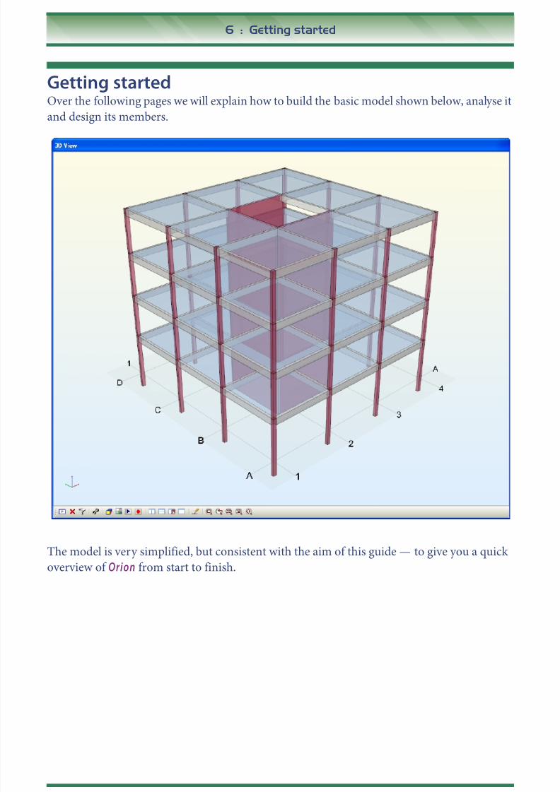
Getting startedOver the following pages we will explain how to build the basic model shown below, analyse it
and design its members.
The model is very simplified, but consistent with the aim of this guide — to give you a quickoverview of Orion from start to finish.

8/20/2019 Orion 18.0_Quick Start Guide 2015
http://slidepdf.com/reader/full/orion-180quick-start-guide-2015 7/62
Getting started : 7
User interfaceThe various components of Orion’s user interface are shown below:
Apart from the Pick icon1, which you use to select any type of member, the Members
Toolbar is arranged in a logical sequence. Generally you create buildings by workingfrom left to right on this toolbar. You can also access the options on this toolbar
from the M a i n m e n u although this is slower than using the icons.
Quick Start conventionsThe aim of these conventions is to enable you to work through this Quick Start example as
quickly as possible.
Menus - For the purpose of this exercise when we refer to Main menu commands we do so
using following syntax:
Pick Run / Beam Section Design and Detailing » Storey Beams'
1. Wherever we refer to an icon you will find a picture of that icon to the right of the text which refers to it.
L a y e r t o o l b a r
Main menu
Structuretree view
3D view
Plan view
Context (mouseright-click) menu
Members toolbar

8/20/2019 Orion 18.0_Quick Start Guide 2015
http://slidepdf.com/reader/full/orion-180quick-start-guide-2015 8/62
8 : Getting started
This means that you should pick item shown below from the Main menu.
Buttons - We shorten the command “Click the Button Name button” to “Click Button Name”.
Steps you must perform - In order to differentiate actions that you need to perform from any
explanatory text we use the easily recognisable font shown below.
Leave the Codes tab unchanged and click Analysis.
First StepsIf you have not yet installed Orion, then insert the CD into your computer’s
CD/DVD drive, and follow the on-screen instructions to install it.
Ensure that you connect the hardware dongle to the appropriate port on
your computer.
Click the Start button on the Windows task bar, then in turn click:• All Programs,
• CSC/Orion1,
• Orion 162.
This loads Orion , and displays the Open Project dialog. You use this both to select an existing
project or to start a new one. You can specify the location of the project by clicking Data
Folder .
1. The start menu folder.
2. The application.
8/20/2019 Orion 18.0_Quick Start Guide 2015
http://slidepdf.com/reader/full/orion-180quick-start-guide-2015 9/62
Getting started : 9
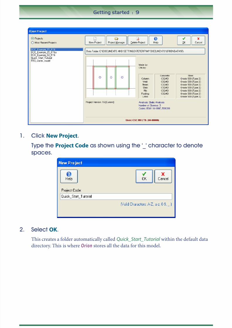
1. Click New Project.
Type the Project Code as shown using the '_' character to denote
spaces.
2. Select OK.This creates a folder automatically called Quick_Start_Tutorial within the default data
directory. This is where Orion stores all the data for this model.

8/20/2019 Orion 18.0_Quick Start Guide 2015
http://slidepdf.com/reader/full/orion-180quick-start-guide-2015 10/62
10 : Getting started
Project SettingsWe now need to choose the settings to be applied to the project.
3. Select the UK (BS8110) template and click Import .
Templates are used to rapidly establish default model parameters: design codes; material
properties; member design settings etc. for the project.
8/20/2019 Orion 18.0_Quick Start Guide 2015
http://slidepdf.com/reader/full/orion-180quick-start-guide-2015 11/62
Getting started : 11
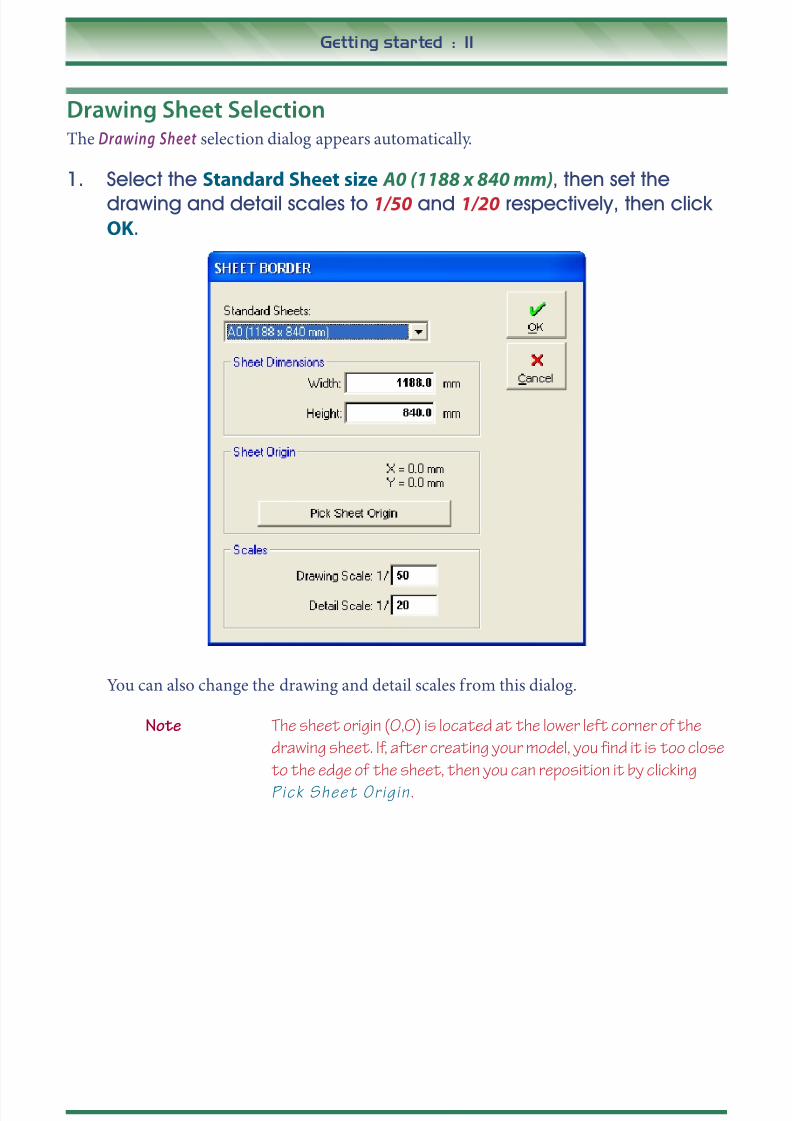
Drawing Sheet SelectionThe Drawing Sheet selection dialog appears automatically.
1. Select the Standard Sheet size A0 (1188 x 840 mm), then set the
drawing and detail scales to 1/50 and 1/20 respectively, then clickOK.
You can also change the drawing and detail scales from this dialog.
Note The sheet origin (0,0) is located at the lower left corner of the
drawing sheet. If, after creating your model, you find it is too close
to the edge of the sheet, then you can reposition it by clicking
P i c k S h e e t O r i g i n .

8/20/2019 Orion 18.0_Quick Start Guide 2015
http://slidepdf.com/reader/full/orion-180quick-start-guide-2015 12/62
12 : Getting started
Inserting Storey Height
The next dialog prompts for the Storey Height of the 1st storey.
1. Enter the storey height as 3300 mm and click OK.
After you enter the height of the 1st storey you will see the main drawing area (Graphic
Editor ). Initially the drawing area is completely empty.

8/20/2019 Orion 18.0_Quick Start Guide 2015
http://slidepdf.com/reader/full/orion-180quick-start-guide-2015 13/62
Getting started : 13
Inserting Additional FloorsNow we will proceed and define the building’s total number of floors.
1. Right click on Storeys in the Structure Tree View to
see the context menu (shown on the right).
2. Choose Insert storey.
3. Enter 4 in the Total No. of Storeys box and click OK.
Note By entering 4 you are telling O r i o n that you want to add storey
4. O r i o n knows that your model only contains a base level at
present, and it will therefore create not only storey 4, but will alsocreate the intermediate storeys 1, 2 and 3 automatically.
If you were to use the dialog on a building which already has
storeys in it, and you entered the number of an existing storey,
then O r i o n would create a new storey at that storey number and
would move the existing storey(s) up to cater for this.

8/20/2019 Orion 18.0_Quick Start Guide 2015
http://slidepdf.com/reader/full/orion-180quick-start-guide-2015 14/62
14 : Selection methods
Selection methodsThis is the first button in the Members toolbar. At the moment the model has no members for
you to select. You will need this general information as you continue to work through the
example, so please take time to read it now.
You select all entities in the same way — using the Pick icon. Selected entities are
also highlighted in the Structure Tree View.
If you click the right mouse button when an entity is selected you will see a
pop-up (context) menu which allows you to edit that entity.
You can select several entities at the same time, simply hold down the CTRL key while you pick
them. You can identify selected entities by the small squares or grips that appear at their ends.
You can also select entities directly from the Structure Tree View . Click the entity name in the
tree view to select it. You can also hold down the CTRL key to selection multiple entities from
the structure tree.
You can also drag with the mouse to access further selection options:
• drag from left to right and you will see a rectangular box. When you release the mouse
button Orion selects all entities that are t o t a l l y c o n t a i n e d w i t h i n the box.
• drag from right to left similarly and Orion selects any entities that are c o n t a i n e d w i t h i n
t h e b o x a n d w h i c h c r o s s i t s b o u n d a r i e s .
• Hold the S h i f t key down and drag to create a line rather than a rectangle. In this case
Orion selects any entities t h a t c r o s s t h e l i n e .
1. As you progress through this example please experiment with
selecting using both the Pick icon and the Structure Tree View
methods.
Note For additional information about selecting single/multiple entities
using the P ic k command refer to the Orion Training Manual .

8/20/2019 Orion 18.0_Quick Start Guide 2015
http://slidepdf.com/reader/full/orion-180quick-start-guide-2015 15/62
Zooming and Panning methods : 15
Zooming and Panning methodsAs with selection there is nothing other than the sheet border with which to
zoom and pan. You will need this general information later in the example. As
with selection we would encourage you to experiment with zooming andpanning as you work through the example.
The most useful zoom commands are:
Zoom Extents - zooms the display so that you can see the selected
object(s).
Zoom Limits - zooms the display so that you can see all the objects that are
within the drawing sheet border.
Zoom Window - Allows you to zoom into an area by dragging a rectangleto define its diametrically opposite corners.
Pan - Allows you to pan the drawing image by holding down the scroll
wheel on the mouse and dragging to a new location in the window.
Note You can Zoom and Pan easily on-the-fly using the mouse.
• If you have a mouse with a scroll wheel, scroll it to zoom in and
out.
• Hold the scroll wheel down and drag to pan the display.
• If you have a three button mouse you can use the middle
button to zoom and pan.

8/20/2019 Orion 18.0_Quick Start Guide 2015
http://slidepdf.com/reader/full/orion-180quick-start-guide-2015 16/62
16 : Defining a grid pattern
Defining a grid patternNow to create the axes in our model. You can either define axes individually by
clicking the Axis icon, or you mayprefer to import them from a DXF drawing. Refer
to the Orion Training Manual for more details of how to import them from DXF.You can also define multiple axes in one go using the Orthogonal Axis Generator . This is the
approach we shall adopt here.
1. Right click on Axes in the Structure Tree View to see the context menu
(shown below).
2. Pick Orthogonal Axis Generator .Note Look at the bottom of the window. The text displayed there tells
you how to proceed.
3. Hold down the CTRL key and pick a point in the lower left hand
region of the drawing sheet.
Note Holding theCTRL key like this ensures the reference point is a
sensible (i.e. whole number) offset from the origin.
4. After you pick the reference point you will see the Orthogonal Axis
Generator dialog.
Note The Orthogonal Axis Generator creates Direction 1 axes
horizontally and gives them Alphabetic labels , It creates Direction
2 axes vertically with Numeric labels. By convention Orion willassign direction 1 to all axes within ±45° to the horizontal and
direction 2 to all axes within ±45° to the vertical.

8/20/2019 Orion 18.0_Quick Start Guide 2015
http://slidepdf.com/reader/full/orion-180quick-start-guide-2015 17/62
Defining a grid pattern : 17
5. Complete the Orthogonal Axis Generator as shown below.
6. Click OK and you will see the axes shown below.
8/20/2019 Orion 18.0_Quick Start Guide 2015
http://slidepdf.com/reader/full/orion-180quick-start-guide-2015 18/62
18 : Defining Materials
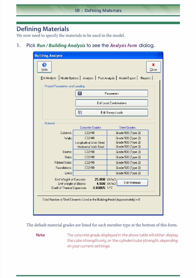
Defining MaterialsWe now need to specify the materials to be used in the model.
1. Pick Run / Building Analysis to see the An al ysi s Fo rm dialog.
The default material grades are listed for each member type at the bottom of this form.
Note The concrete grade displayed in the above table will either display
the cube strength only, or the cylinder/cube strength, depending
on your current settings.

8/20/2019 Orion 18.0_Quick Start Guide 2015
http://slidepdf.com/reader/full/orion-180quick-start-guide-2015 19/62
Defining Materials : 19
2. Click Edit Materials .
3. Click the Columns/Concrete Grades box, highlight C25/30 and checkthe box Apply to All Member Types.
Note You could apply an alternative grade or adjust the modulus of
elasticity of an existing grade from here.

8/20/2019 Orion 18.0_Quick Start Guide 2015
http://slidepdf.com/reader/full/orion-180quick-start-guide-2015 20/62
20 : Defining Materials
4. Click OK to return to the Materials tab.
This will set all structural members to have Grade 30 Concrete.
Note The unit weight of concrete is set on this screen also. In this
example 25kN/m3
is used.
5. Repeat the same process if necessary for the Steel Grade. Set all
structural members to use bars of Grade 500 (Type 2) and a Material
Factor of 1.15.
Note The above Grade and Material Factor are appropriate for design
to BS 8110:1997 in the UK. For other codes/regions you may be
required to adjust these.
Next we will set the bar diameters which we want Orion to consider when it performs the
reinforcement design for each member type.
6. Click Dia (the one on the Columns row).
You will notice that some bars sizes are selected by default, and you may find that the
defaults you see may not be the same as those shown in the capture below. You can
prevent Orion using a bar size by removing the tick in its Use box. Conversely you can
allow Orion to use a bar size by ticking its Use box.
7. Make the settings shown above, or different settings if you prefer.
Repeat this process for the other member types also.

8/20/2019 Orion 18.0_Quick Start Guide 2015
http://slidepdf.com/reader/full/orion-180quick-start-guide-2015 21/62
Defining Materials : 21
Note If you do make different settings, then you may achieve different
results later in this example.
8. Select OK to return to the Materials dialog which looks as shown
below.
9. Select OK once more to return to the Building Analysis form and then
Close.

8/20/2019 Orion 18.0_Quick Start Guide 2015
http://slidepdf.com/reader/full/orion-180quick-start-guide-2015 22/62
22 : Defining Columns
Defining Columns1. Click the Column icon or pick Member / Column.
2. Enter b1,b2, e1 and e2 as shown below. The dimensions are
explained by the diagram to the right of the dialog.
Note You can right click in each box and select from the available
dimensions instead of typing.
These properties will create a 250 x 200 sized column with the 250 dimension in
direction 1. These columns are also parallel to the grids in both directions 1 and 2.
3. To position columns click and drag from axis A-1 to axis A-4.
Tip You might like to try out some of the zooming and panning
methods on page 15 to view the area of interest at this point.
4. Next position single columns by clicking at the following grid
intersections: B-1, B-4, C-1, C-4.
Dir-2 Axis
Dir-1 Axis b 2
e 2
e1
b1
Columnreferencepoint
8/20/2019 Orion 18.0_Quick Start Guide 2015
http://slidepdf.com/reader/full/orion-180quick-start-guide-2015 23/62
Defining Columns : 23
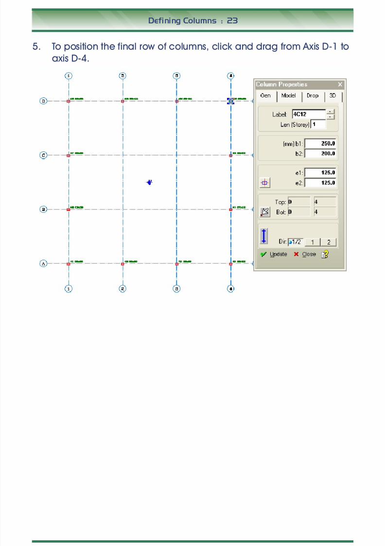
5. To position the final row of columns, click and drag from Axis D-1 to
axis D-4.

8/20/2019 Orion 18.0_Quick Start Guide 2015
http://slidepdf.com/reader/full/orion-180quick-start-guide-2015 24/62
24 : Creating Walls
Creating Walls1. Click the Wall icon or pick Member - Wall .
2. Enter a b: dimension of 200, and a b2: dimension of 100. Also
enter a value of 100 for both Ext. I: and J:. The dimensions
are explained by the diagram below.
3. Insert the wall by clicking and dragging from the start grid B-2 to
C-2.
4. Do the same at Grid C-2 to C-3 and Grid B-2 to B-3. You should now
have the arrangement of walls shown below.
‘I’ ‘J’
b
2 b
I-ext J-ext
Shear wall reference points
Shear wallinsertion axis
8/20/2019 Orion 18.0_Quick Start Guide 2015
http://slidepdf.com/reader/full/orion-180quick-start-guide-2015 25/62
Creating Beams : 25
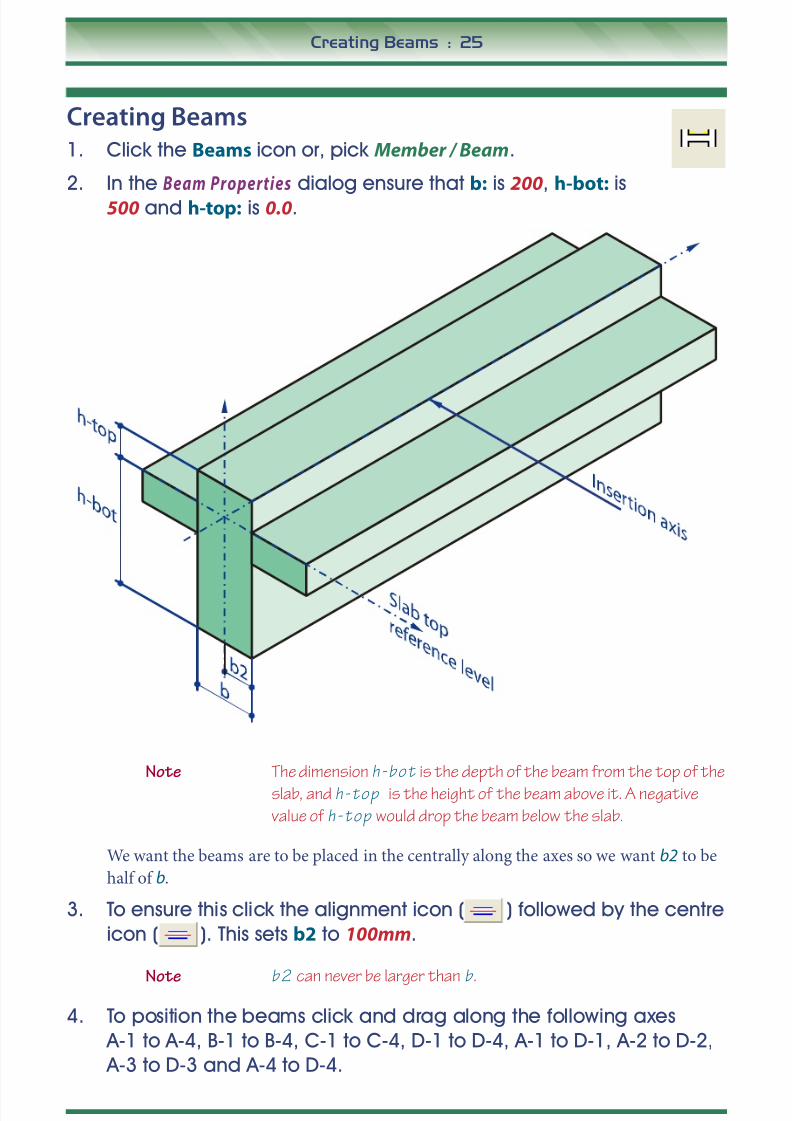
Creating Beams1. Click the Beams icon or, pick Member / Beam.
2. In the Beam Properties dialog ensure that b: is 200, h-bot: is
500 and h-top: is 0.0.
Note The dimension h - b o t is the depth of the beam from the top of the
slab, and h - t o p is the height of the beam above it. A negative
value of h - t o p would drop the beam below the slab.
We want the beams are to be placed in the centrally along the axes so we want b2 to be
half of b.
3. To ensure this click the alignment icon ( ) followed by the centre
icon ( ). This sets b2 to 100mm.
Note b 2 can never be larger than b .
4. To position the beams click and drag along the following axes
A-1 to A-4, B-1 to B-4, C-1 to C-4, D-1 to D-4, A-1 to D-1, A-2 to D-2,
A-3 to D-3 and A-4 to D-4.

8/20/2019 Orion 18.0_Quick Start Guide 2015
http://slidepdf.com/reader/full/orion-180quick-start-guide-2015 26/62
26 : Creating Beams
Note Like the columns the beams are automatically labelled based on
the storey and numbered sequentially as they are entered.
Note O r i o n automatically splits the beam into three individual
members between the columns.
Note A beam will not be placed where a wall already exists. For example,
dragging along grid line B created two additional beams, not 3.
Your screen should now look like this.

8/20/2019 Orion 18.0_Quick Start Guide 2015
http://slidepdf.com/reader/full/orion-180quick-start-guide-2015 27/62
Creating Slabs : 27
Creating SlabsNow we shall create the 4th storey slabs.
1. Click the Slab icon or pick Member / Slab.
2. In the Slab Properties dialog enter the slab thickness h: to be
200 and the Concrete cover to be 25 mm.
3. Click on the Loads tab and enter an additional Dead Load of 1.2 kN/
m2.
4. In the Imp. Load box do a right mouse click and select a value of 4.0
kN/m2.
Note O r i o n calculates the self-weight of the slab automatically from
its thickness and the concrete density (specified earlier when
defining materials).

8/20/2019 Orion 18.0_Quick Start Guide 2015
http://slidepdf.com/reader/full/orion-180quick-start-guide-2015 28/62
28 : Creating Slabs
5. Return to the General tab, click the Type box and you will see a
pop-up menu of all possible Slab Types.
Note The Sla b T ype relates to table 3.14 in the code and is used to
obtain correct reinforcement values, based on the coefficient
method. For ease in creating this model we will leave the Slab Type
as 1 initially. Once all the slabs exist we can tell O r i o n to calculate
the correct type for each slab automatically.
6. To create the first slab position the cursor in the square between grid
points A-1 and B-2 and left-click.

8/20/2019 Orion 18.0_Quick Start Guide 2015
http://slidepdf.com/reader/full/orion-180quick-start-guide-2015 29/62
Creating Slabs : 29
You will see your first slab — 4S1 as below, this also includes the yield line for the slab
load distribution.
Note If the slab does not appear as shown above, click the Insertion
button and ensure the insertion method is set to Beam Region .
If yield lines are not visible, these can be activated as follows. Pick
Settings/View Settings/Slabs. Check the box D i s p l a y Y i e l d
L i n e s .

8/20/2019 Orion 18.0_Quick Start Guide 2015
http://slidepdf.com/reader/full/orion-180quick-start-guide-2015 30/62
30 : Creating Slabs
7. Repeat the above process to define seven more slabs to achieve
the layout shown below:
Setting Slab Types AutomaticallyTo set the slab types in accordance with BS 8110 Table 3.14 automatically, proceed as follows:
1. To clear the selection of any members click the Clear
Selection Set icon.
2. Right mouse click the Slabs folder in the Structure Tree andselect Set Slab Types Automatically .

8/20/2019 Orion 18.0_Quick Start Guide 2015
http://slidepdf.com/reader/full/orion-180quick-start-guide-2015 31/62
Creating Slabs : 31
3. You will see the Slab Type Determination dialog.
4. Click OK to proceed. Orion determines the slab types.
5. Click OK once more to close the Messages dialog.
Note At this point the model is ready for various types of analysisand design. If you are in a hurry, you could skip to page 41 anddo this. We are going to cover a few other useful options first.
8/20/2019 Orion 18.0_Quick Start Guide 2015
http://slidepdf.com/reader/full/orion-180quick-start-guide-2015 32/62
32 : Creating Slabs
Creating Ribbed SlabsAs an alternative to normal and flat slabs you can also define and use ribbed and
waffle slabs. These slabs types are not within the scope of this Quick Start Guide.
For further information on these types of slab refer to the Structure Modelling topic in theOrion Help system.
Slab Design and DetailingFor beam/slab models (as opposed to flat slab), you determine slab reinforcement
requirements by inserting slab strips in the X & Y directions. This then automatically
determines the reinforcement required for the different slab types by using Table 3.14 from
BS 8110.
Strips provide flexibility to design and detail reinforcement in any plan orientation. This
enables very complex floor layouts to be designed and detailed.
The slab strips parallel to the horizontal axes will be labelled X1, X2… and those parallel to
the vertical direction axes will be labelled Y1, Y2…
First we will define a strip labelled X1 through the slabs between grid lines A-B and which
cross grid lines 1 to 5.
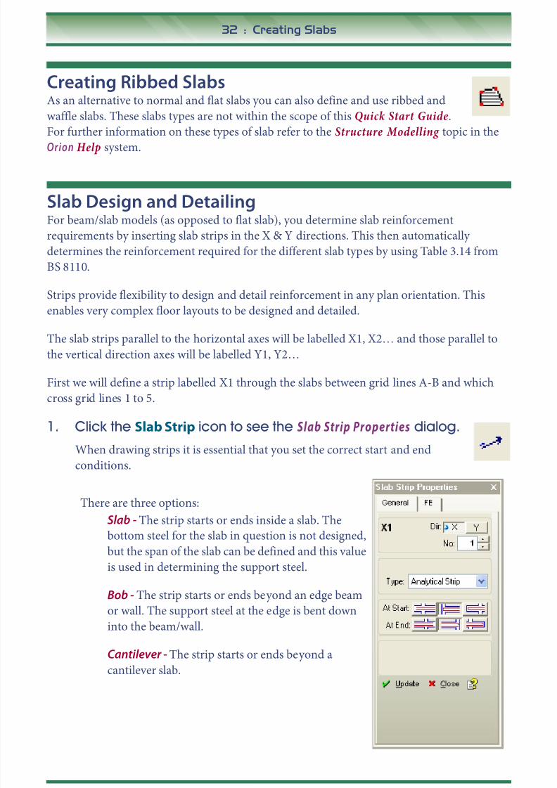
1. Click the Slab Strip icon to see the Slab Strip Properties dialog.
When drawing strips it is essential that you set the correct start and end
conditions.
There are three options:
Slab - The strip starts or ends inside a slab. The
bottom steel for the slab in question is not designed,
but the span of the slab can be defined and this valueis used in determining the support steel.
Bob - The strip starts or ends beyond an edge beam
or wall. The support steel at the edge is bent down
into the beam/wall.
Cantilever - The strip starts or ends beyond a
cantilever slab.

8/20/2019 Orion 18.0_Quick Start Guide 2015
http://slidepdf.com/reader/full/orion-180quick-start-guide-2015 33/62
Creating Slabs : 33
2. Ensure the label is X1 and indicate a Bob at both the start and end
of the strip by clicking on the appropriate end conditions as shown
above.
3. Position your cursor above Grid A but to the left of Grid 1 (so that it is
not in the model). Now press and hold the CTRL1 key and at thesame time click and drag to create a horizontal line which extends
past Grid 4.
Your screen should look similar to this.
Note We specified the bar sizes which O r i o n can use in slab designearlier (see “Defining Materials” on page 18.) You can also control
the slab bar spacing range that will be applied by picking S e t t i n g s
/ G r a p h i c a l E d i t o r S e t t i n g s / S l a b R e i n f o r c e m e n t 1 .
4. Create another similar strip labelled X2 by repeating the process for
the slabs between grid lines B-C starting to the left of grid line 1 and
ending to the right of grid line 2.
1. This ensures that the strip you create is completely horizontal.

8/20/2019 Orion 18.0_Quick Start Guide 2015
http://slidepdf.com/reader/full/orion-180quick-start-guide-2015 34/62
34 : Creating Slabs
5. Draw a third strip and a fourth strip in the X direction to achieve the
layout below.
6. Now we can insert some vertical strips. Create strip Y1 between grid
lines 1 and 2 and which extends from below grid line A to beyond
grid line D.

8/20/2019 Orion 18.0_Quick Start Guide 2015
http://slidepdf.com/reader/full/orion-180quick-start-guide-2015 35/62
Creating Slabs : 35
7. Create additional strips Y2, Y3 and Y4 as shown below:
We can now re-check strips as a batch and create a report.
8. Pick Run / Slab Analysis and Design.
8/20/2019 Orion 18.0_Quick Start Guide 2015
http://slidepdf.com/reader/full/orion-180quick-start-guide-2015 36/62
36 : Creating Slabs
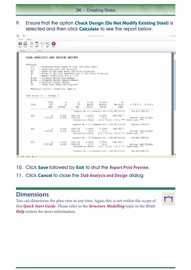
9. Ensure that the option Check Design (Do Not Modify Existing Steel) is
selected and then click Calculate to see the report below:
10. Click Save followed by Exit to shut the Report Print Preview .
11. Click Cancel to close the Slab Analysis and Design dialog.
DimensionsYou can dimension the plan view at any time. Again this is not within the scope of
this Quick Start Guide. Please refer to the Structure Modelling topic in the Orion
Help system for more information.
8/20/2019 Orion 18.0_Quick Start Guide 2015
http://slidepdf.com/reader/full/orion-180quick-start-guide-2015 37/62
Sections : 37
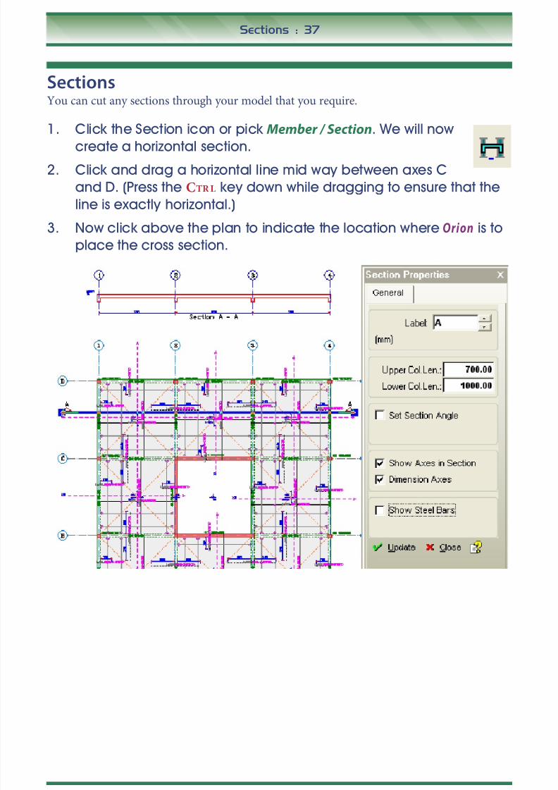
SectionsYou can cut any sections through your model that you require.
1. Click the Section icon or pick Member / Section. We will now
create a horizontal section.
2. Click and drag a horizontal line mid way between axes C
and D. (Press the CTRL key down while dragging to ensure that the
line is exactly horizontal.)
3. Now click above the plan to indicate the location where Orion is to
place the cross section.

8/20/2019 Orion 18.0_Quick Start Guide 2015
http://slidepdf.com/reader/full/orion-180quick-start-guide-2015 38/62
38 : Sections
4. In the Section Properties dialog, tick Show Steel Bars and click Update.
You will now see the bars required at this cross section as shown
below.
Slab LoadsYou add Slab-point, -line and -patch loads using this command. This is not within
the remit of this Quick Start Guide. Refer to the more comprehensive model in the
Training Notes for an example and/or refer to the Structure Modelling topic in the
Orion Help system for more information.
Slab OpeningsAgain refer to the more comprehensive model in the Training Notes for an example
of applying slab openings, and/or refer to the Structure Modelling topic in the
Orion Help system for more information.

8/20/2019 Orion 18.0_Quick Start Guide 2015
http://slidepdf.com/reader/full/orion-180quick-start-guide-2015 39/62
Generating a 3D View of the Model : 39
Generating a 3D View of the ModelOrion allows you to obtain a 3D view of the model, and to choose different layouts of Plan- (P)
and 3D-view windows. You can create different 3D views in different windows. To switch
between the different views use the tabs located at the bottom left of the Graphic Editor .
1. Choose the tab shown on the right to tile a 3D view and plan
view horizontally as shown below:
Note Although information has only been defined at ST04, all the lower
storeys have been created automatically. The program assumesthat unless a floor has at least one member defined, it is to be an
exact duplicate of the floor above.
2. Click the 3D View to make its window active.
You can manipulate the 3D View in a number of ways:
• To spin, pan or zoom the image dynamically click and drag the right mouse button, turn
the mouse scroll wheel or hold the scroll wheel down and drag.• To change the way the 3D View is displayed use the 3D View Settings icon.
8/20/2019 Orion 18.0_Quick Start Guide 2015
http://slidepdf.com/reader/full/orion-180quick-start-guide-2015 40/62
40 : Generating a 3D View of the Model
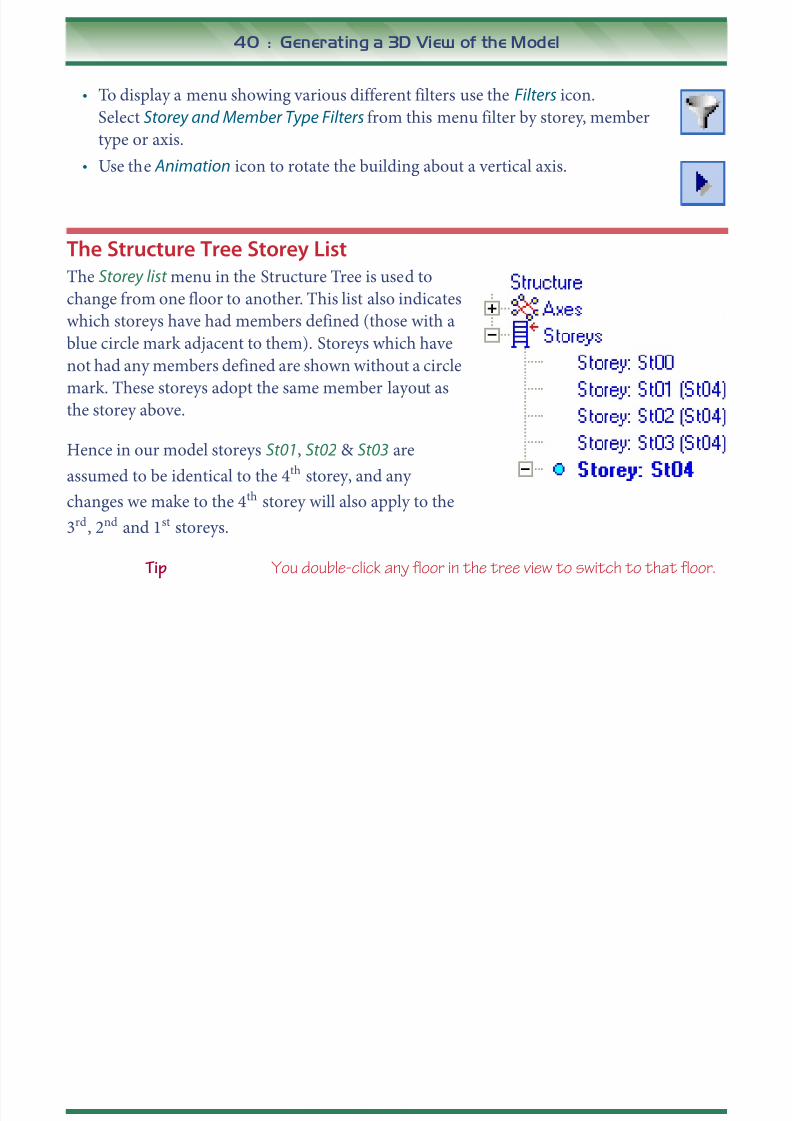
• To display a menu showing various different filters use the Filters icon.
Select Storey and Member Type Filters from this menu filter by storey, member
type or axis.
• Use the Animation icon to rotate the building about a vertical axis.
The Structure Tree Storey ListThe Storey list menu in the Structure Tree is used to
change from one floor to another. This list also indicates
which storeys have had members defined (those with a
blue circle mark adjacent to them). Storeys which have
not had any members defined are shown without a circle
mark. These storeys adopt the same member layout asthe storey above.
Hence in our model storeys St01, St02 & St03 are
assumed to be identical to the 4th storey, and any
changes we make to the 4th storey will also apply to the
3rd, 2nd and 1st storeys.
Tip You double-click any floor in the tree view to switch to that floor.

8/20/2019 Orion 18.0_Quick Start Guide 2015
http://slidepdf.com/reader/full/orion-180quick-start-guide-2015 41/62
Building Analysis and Design : 41
Building Analysis and DesignThe building can now be analysed.
1. Pick Run / Building Analysis to see the An al ysi s Fo rm dialog.
Pre-Analysis SettingsThe following function buttons are available from here:
Parameters allows you to review and/or modify any building parameters you may havedefined.
Edit Load Combinations allows you to review and/or modify an existing set of load
combinations. You can also create new load combination sets from here using the
Loading Generator.

8/20/2019 Orion 18.0_Quick Start Guide 2015
http://slidepdf.com/reader/full/orion-180quick-start-guide-2015 42/62
42 : Building Analysis and Design
Edit Storey Loads allows you to review and/or modify any lateral load cases applied at
each storey. Automatically generated lateral loads are only available after completing the
analysis data preparation stage.
Edit Materials allows you to review and/or modify the concrete and steel material
properties.
Building Analysis Model Options
1. Click the Model Options tab and set the options as shown below.
The various analysis parameters here are fully described in the Orion Help system and
Engineer's Handbook.

8/20/2019 Orion 18.0_Quick Start Guide 2015
http://slidepdf.com/reader/full/orion-180quick-start-guide-2015 43/62
Building Analysis and Design : 43
The Analysis Tab
1. Pick the Analysis tab.
Before we analyse the model let’s check its validity.

8/20/2019 Orion 18.0_Quick Start Guide 2015
http://slidepdf.com/reader/full/orion-180quick-start-guide-2015 44/62
44 : Building Analysis and Design
2. Click Building Model Check .
This will check that the building is valid for those conditions indicated.
3. Choose All Storeys and then click Check .

8/20/2019 Orion 18.0_Quick Start Guide 2015
http://slidepdf.com/reader/full/orion-180quick-start-guide-2015 45/62
Building Analysis and Design : 45
Note Even if this process doesn’t find any errors, it doesn't guarantee
that the building is modelled correctly. There may be other
problems in the model that are not picked up by the validity
checking process.
4. Assuming that there are no errors click Close to shut the dialog.
Running the AnalysisBuilding Analysis is performed from the Analysis tab. Optionally after the analysis is
complete, Orion can automatically perform Column/Wall Reinforcement Design and Beam
Reinforcement Design for all members in the building.
1. Click (Un)Check All to activate the optional Column/Wall and Beam
designs. (At this stage there is no need to re-select Steel Bars.)
2. Click Start to begin the batch analysis and design process.
Orion analyses the building and designs all the columns, walls and beams.
3. When the analysis has completed click OK.
Cross Checking the Analysis Results
An important cross check on the validity of the analysis is the Axi al Lo ad Co mp ar is on Rep or t .This report sums all the dead and live loads applied at each storey level and also displays the
axial forces in the columns and shear walls. These values should be within a few percent of
each other. If this is not the case, then you need to determine the reason for any discrepancy.
The report can be automatically displayed at the end of the analysis process if any warnings
have occurred during the cross checking process.
1. Pick Axial Load Comparison Report.

8/20/2019 Orion 18.0_Quick Start Guide 2015
http://slidepdf.com/reader/full/orion-180quick-start-guide-2015 46/62
46 : Building Analysis and Design
An example axial load comparison report is given below.
You can print this report, or save it for later inclusion in a batch print out of all thereports created by Orion for this model.
Normally the total “SUM OF APPLIED LOADS (Using Un-Decomposed Slab Loads)”
values should be similar to those from the Decomposed Slab Loads table.
8/20/2019 Orion 18.0_Quick Start Guide 2015
http://slidepdf.com/reader/full/orion-180quick-start-guide-2015 47/62
Building Analysis and Design : 47
Provided that you can account for any difference between the un-decomposed and the
decomposed values, you should compare the Total Decomposed Applied Dead Load
with the Total Delta G value from the “BUILDING ANALYSIS COLUMN/
SHEARWALL AXIAL LOADS” table.
Similarly, you should compare Total Decomposed Live Load against Total Delta Q.You must be able to account for any differences in these values.
Note In more complicated models there are often small percentage
differences, but they should never be more than a few percent.
2. Click Save and then click to Exit the report.
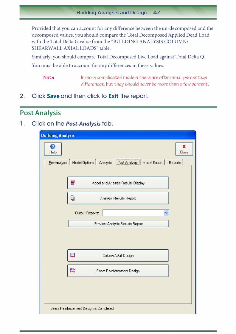
Post Analysis
1. Click on the Post-Analysis tab.

8/20/2019 Orion 18.0_Quick Start Guide 2015
http://slidepdf.com/reader/full/orion-180quick-start-guide-2015 48/62
48 : Building Analysis and Design
The buttons on the Post Analysis tab are as follows:
• Model and Analysis Results Display provides a graphical means of reviewing the analysis
results.
• Analysis Results Report configures the numerical analysis results as required. These can
then be can selected through the Output Reports: dropdown list, then previewed andprinted through Preview Analysis Results Report .
• Column/Shearwall Design and Beam Reinforcement Design can be accessed from here
also.
2. Pick Model and Analysis Results Display.
The View Settings menu is shown on the left of the window. This can be used to control the
appearance of the display. The most commonly used settings can also be accessed from the
icons and drop down menus at the top of the window.

8/20/2019 Orion 18.0_Quick Start Guide 2015
http://slidepdf.com/reader/full/orion-180quick-start-guide-2015 49/62
Building Analysis and Design : 49
3. Click the Filters icon from the top of the screen and hide all axes
apart from axis A.
4. Use the right mouse button to rotate the frame to a front view, anduse the scroll wheel to zoom in and out.
5. Click the Displacements icon to turn off the display of the defelected
shape.
6. Click the Frame Element Results Diagrams icon to select it and then
choose the M3 as the required effect to display from the drop down
menu to the right of the icon as shown below.

8/20/2019 Orion 18.0_Quick Start Guide 2015
http://slidepdf.com/reader/full/orion-180quick-start-guide-2015 50/62
50 : Building Analysis and Design
7. Uncheck Diagrams/Automatic Scale from the View Settings menu to
activate the Display Scale. Experiment with the scale to obtain a plot
similar to that shown below:
8. Experiment with the filters and effects to create other plots and then
close the Anal ys is Mo del and Re sul ts window.
9. Close the Building Analysis dialog.

8/20/2019 Orion 18.0_Quick Start Guide 2015
http://slidepdf.com/reader/full/orion-180quick-start-guide-2015 51/62
Column Design : 51
Column Design1. Pick Run / Column Section Design.
Note The designs you obtain are very dependant on the currentSettings. You can adjust these to suit your own preferences
through the Settings menu. Hence don’t be surprised if your
results differ from those shown below. For example in the results
below the minimum column bar size has been set to H12.
Since you requested a column design as part of the building analysis process all the
columns have already been batch designed. You can thus proceed to create a reportimmediately.

8/20/2019 Orion 18.0_Quick Start Guide 2015
http://slidepdf.com/reader/full/orion-180quick-start-guide-2015 52/62
52 : Column Design
2. Pick File / Column Reinforcement Design Report .
3. Close the report.
You can also generate a column schedule quickly.

8/20/2019 Orion 18.0_Quick Start Guide 2015
http://slidepdf.com/reader/full/orion-180quick-start-guide-2015 53/62
Column Design : 53
4. Pick File - Column Schedule. Highlight several of the columns as
shown, and then click Draw.
Note You may see a dialog telling you the size of sheet you require and
the drawing scale. If you do, then simply click O K to continue.
8/20/2019 Orion 18.0_Quick Start Guide 2015
http://slidepdf.com/reader/full/orion-180quick-start-guide-2015 54/62
54 : Column Design
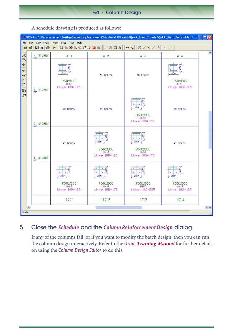
A schedule drawing is produced as follows:
5. Close the Schedule and the Column Reinforcement Design dialog.
If any of the columns fail, or if you want to modify the batch design, then you can run
the column design interactively. Refer to the Orion Training Manual for further details
on using the Column Design Editor to do this.

8/20/2019 Orion 18.0_Quick Start Guide 2015
http://slidepdf.com/reader/full/orion-180quick-start-guide-2015 55/62
Beam Design : 55
Beam Design1. Pick Run / Beam Section Design and Detailing - Storey Beams.
Note The designs you obtain are very dependant on the currentSettings. You can adjust these to suit your own preferences
through the Settings menu. Hence don’t be surprised if your
results differ from those shown below.
Since you set the option to batch design the beams as part of the building analysis you
can view the results immediately.
As with the column design, If any of the beams fail, or if you want to modify the batch
design, then you can run the design interactively. Refer to the Orion Training Manual
for details of how to do this.
Those beams that have been successfully designed can be placed on to a drawing sheet
automatically.

8/20/2019 Orion 18.0_Quick Start Guide 2015
http://slidepdf.com/reader/full/orion-180quick-start-guide-2015 56/62
56 : Beam Design
2. Pick Sheet - Beam Detail Drawings of All Axes (Single Sheet) and check
Storey-1
3. Set the Number of Columns in the Sheet to 1 and click OK to createthe drawing.
4. Close the drawing.

8/20/2019 Orion 18.0_Quick Start Guide 2015
http://slidepdf.com/reader/full/orion-180quick-start-guide-2015 57/62
Beam Design : 57
5. Now to create a report pick File / Beam Reinforcement Design Report .
6. Click Save, and then Close the report and Close the Beam Design
window.

8/20/2019 Orion 18.0_Quick Start Guide 2015
http://slidepdf.com/reader/full/orion-180quick-start-guide-2015 58/62
58 : Beam Design
Design StatusYou can graphically display the design status of all members on a particular floor.
1. Click Design Status from the bottom of the Structure tree view as shown.
The members are shown colour coded as follows:
• Green = PASS,
• Red = FAIL - insufficient area of steel provided,
• Unhatched = FAIL? - although a sufficient area of steel has been provided, the
member still fails due to spacing requirements.
Note The design status of each member is also indicated in the
Structure tree view.
8/20/2019 Orion 18.0_Quick Start Guide 2015
http://slidepdf.com/reader/full/orion-180quick-start-guide-2015 59/62
Quantity Extraction Tables : 59
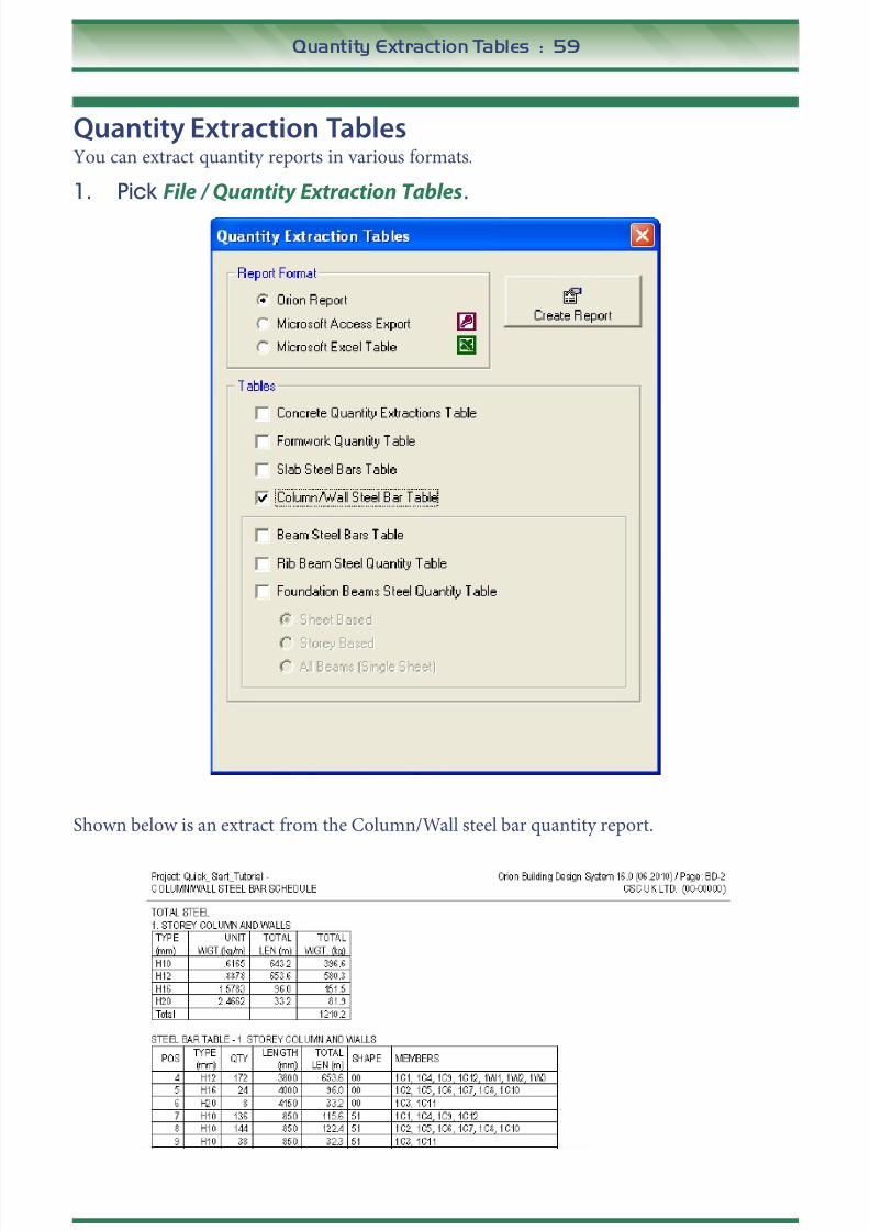
Quantity Extraction TablesYou can extract quantity reports in various formats.
1. Pick File / Quantity Extraction Tables.
Shown below is an extract from the Column/Wall steel bar quantity report.

8/20/2019 Orion 18.0_Quick Start Guide 2015
http://slidepdf.com/reader/full/orion-180quick-start-guide-2015 60/62
60 : Report Manager
Report ManagerYou can merge all saved reports into a single report for printing in one go. This also ensures
consistent page numbering.
1. Pick File / Report Manager .
You can combine the separate reports which you created earlier in any order and then print
them.

8/20/2019 Orion 18.0_Quick Start Guide 2015
http://slidepdf.com/reader/full/orion-180quick-start-guide-2015 61/62
What Next? : 61
What Next?In this very simple example you have created and analysed a small model, this may give you
the confidence to go on and try something for yourself.
There is much more help and information provided with Orion.
• The Orion Training Notes – complete notes for introductory Orion training (particularly
recommended).
• The Engineer’s Handbook – accessed from Orion’s Help menu. This provides a great deal
of information on topics such as Finite Element analysis.
Alternatively, we strongly recommend that you attend one of our Orion training courses1. Our
expert, highly acclaimed, tuition will give you a flying start.
1. Contact our Support Department for details.

8/20/2019 Orion 18.0_Quick Start Guide 2015
http://slidepdf.com/reader/full/orion-180quick-start-guide-2015 62/62
62 : What Next?


