Origins and Overview of the Shaped Sonic Boom ... · Origins and Overview of the Shaped Sonic Boom...
14
American Institute of Aeronautics and Astronautics 1 Origins and Overview of the Shaped Sonic Boom Demonstration Program Joseph W. Pawlowski * , David H. Graham † , and Charles H. Boccadoro ‡ Northrop Grumman Corporation – Integrated Systems Sector, El Segundo, California, 90245 Peter G. Coen § NASA Langley Research Center, Hampton, Virginia, 23681 and Domenic J. Maglieri ** Eagle Aeronautics, Inc., Hampton, Virginia, 23669 The goal of the DARPA Shaped Sonic Boom Demonstration (SSBD) Program was to demonstrate for the first time in flight that sonic booms can be substantially reduced by incorporating specialized aircraft shaping techniques. Although mitigation of the sonic boom via specialized shaping techniques was theorized decades ago, until now, this theory had never been tested with a flight vehicle subjected to actual flight conditions in a real atmosphere. The demonstrative success, which occurred on 27 August 2003 with repeat flights in the supersonic corridor at Edwards Air Force Base, is a critical milestone in the development of next generation supersonic aircraft that could one day fly unrestricted over land and help usher in a new era of time-critical air transport. Pressure measurements obtained on the ground and in the air confirmed that the specific modifications made to a Northrop Grumman F-5E aircraft not only changed the shape of the shock wave signature emanating from the aircraft, but also produced a “flat-top” signature whose shape persisted, as predicted, as the pressure waves propagated through the atmosphere to the ground. This accomplishment represents a major advance towards reducing the startling and potentially damaging noise of a sonic boom. This paper describes the evolution of the SSBD program, including the rationale for test article selection, and provides an overview of the history- making accomplishments achieved during the SSBD effort, as well as, the follow-on NASA Shaped Sonic Boom Experiment (SSBE) Program, whose goal was to further evaluate the characteristics and robustness of shaped boom signatures. Nomenclature Acronyms: AEDC = Arnold Engineering Development Center AFB = Air Force Base CFD = Computational Fluid Dynamics CRADA = Cooperative Research and Development Agreement DARPA = Defense Advanced Research Projects Agency FRR = Flight Readiness Review GTOW = Gross Take-Off Weight HSCT = High Speed Supersonic Commercial Transport * SSBD/SSBE Project Manager, Advanced Systems Design, 8D20/W6, AIAA member. † SSBD Chief Aerodynamicist, Advanced Flight Sciences, 9V11/W6, AIAA member. ‡ Manager, Future Strike Systems, XG00/W6, AIAA Associate Fellow. § Supersonic Vehicle Sector Manager, MS 254, AIAA member. ** Projects Director, 13 West Mercury Boulevard, AIAA Associate Fellow. https://ntrs.nasa.gov/search.jsp?R=20050165091 2020-05-27T09:24:25+00:00Z
Transcript of Origins and Overview of the Shaped Sonic Boom ... · Origins and Overview of the Shaped Sonic Boom...

American Institute of Aeronautics and Astronautics
1
Origins and Overview of the Shaped Sonic Boom Demonstration Program
Joseph W. Pawlowski*, David H. Graham†, and Charles H. Boccadoro‡ Northrop Grumman Corporation – Integrated Systems Sector, El Segundo, California, 90245
Peter G. Coen§ NASA Langley Research Center, Hampton, Virginia, 23681
and
Domenic J. Maglieri** Eagle Aeronautics, Inc., Hampton, Virginia, 23669
The goal of the DARPA Shaped Sonic Boom Demonstration (SSBD) Program was to demonstrate for the first time in flight that sonic booms can be substantially reduced by incorporating specialized aircraft shaping techniques. Although mitigation of the sonic boom via specialized shaping techniques was theorized decades ago, until now, this theory had never been tested with a flight vehicle subjected to actual flight conditions in a real atmosphere. The demonstrative success, which occurred on 27 August 2003 with repeat flights in the supersonic corridor at Edwards Air Force Base, is a critical milestone in the development of next generation supersonic aircraft that could one day fly unrestricted over land and help usher in a new era of time-critical air transport. Pressure measurements obtained on the ground and in the air confirmed that the specific modifications made to a Northrop Grumman F-5E aircraft not only changed the shape of the shock wave signature emanating from the aircraft, but also produced a “flat-top” signature whose shape persisted, as predicted, as the pressure waves propagated through the atmosphere to the ground. This accomplishment represents a major advance towards reducing the startling and potentially damaging noise of a sonic boom. This paper describes the evolution of the SSBD program, including the rationale for test article selection, and provides an overview of the history-making accomplishments achieved during the SSBD effort, as well as, the follow-on NASA Shaped Sonic Boom Experiment (SSBE) Program, whose goal was to further evaluate the characteristics and robustness of shaped boom signatures.
Nomenclature Acronyms: AEDC = Arnold Engineering Development Center AFB = Air Force Base CFD = Computational Fluid Dynamics CRADA = Cooperative Research and Development Agreement DARPA = Defense Advanced Research Projects Agency FRR = Flight Readiness Review GTOW = Gross Take-Off Weight HSCT = High Speed Supersonic Commercial Transport
* SSBD/SSBE Project Manager, Advanced Systems Design, 8D20/W6, AIAA member. † SSBD Chief Aerodynamicist, Advanced Flight Sciences, 9V11/W6, AIAA member. ‡ Manager, Future Strike Systems, XG00/W6, AIAA Associate Fellow. § Supersonic Vehicle Sector Manager, MS 254, AIAA member. **Projects Director, 13 West Mercury Boulevard, AIAA Associate Fellow.
https://ntrs.nasa.gov/search.jsp?R=20050165091 2020-05-27T09:24:25+00:00Z

American Institute of Aeronautics and Astronautics
2
HSR = High Speed Research ISSM = Inlet Spillage Shock Measurement LFC = Laminar Flow Control MDO = Multiple Disciplinary Optimization MFR = Mass Flow Ratio MSL = Mean Sea Level NAS = Naval Air Station NASA = National Aeronautics and Space Administration NAVAIR = Naval Air Systems Command NGC = Northrop Grumman Corporation PDR = Preliminary Design Review QSP = Quiet Supersonic Platform RPV = Remotely Piloted Vehicle SCR = Supersonic Cruise Research SFC = Specific Fuel Consumption SSBD = Shaped Sonic Boom Demonstration SSBDWG = Shaped Sonic Boom Demonstration Working Group SSBE = Shaped Sonic Boom Experiment UAV = Unmanned Aerial Vehicle WTM = Wind Tunnel Model Symbols: Ae = equivalent area, square feet Alt = altitude, feet ∆p = delta pressure relative to local freestream static pressure, pounds/square feet f(τ) = Whitham f function H, h = height, feet h/L, h/l = height-to-length ratio, dimensionless H sig = signature altitude, feet L, l = aircraft length, for the SSBD aircraft L = 49.8 feet L/D = lift/drag ratio, dimensionless M = Mach number Rdg = wind tunnel test reading T/W = engine thrust/weight ratio, dimensionless W, WT = weight, pounds X = distance, feet Xe = equivalent length, feet τ = dimensionless integration variable in Whitham f function
I. Introduction joint industry/government team led by Northrop Grumman Corporation (NGC), and including the Defense Advanced Research Projects Agency (DARPA) and the National Aeronautics and Space Administration
(NASA), has demonstrated for the first time in flight that the sonic boom overpressure created when an aircraft breaks the sound barrier can be substantially reduced through vehicle shaping. Currently, civil supersonic flight is prohibited over the United States and most other nations due to the disruption and annoyance caused by sonic booms. Mitigation of the sonic boom via specialized shaping techniques was theorized nearly four decades ago but, until now, this theory had never been tested with a flight vehicle subjected to actual flight conditions in a real atmosphere. The demonstrative success, which occurred on 27 August 2003 with repeat flights in the supersonic corridor at Edwards Air Force Base, is a critical milestone in the development of next generation supersonic aircraft that could one day fly unrestricted over land and help usher in a new era of time-critical air transport. Pressure measurements obtained on the ground and in the air confirmed that the specific modifications made to a Northrop Grumman F-5E aircraft not only changed the shape of the shock wave signature emanating from the aircraft, but also produced a “flat-top” signature whose shape persisted, as predicted, as the pressure waves propagated through the atmosphere to the ground. This accomplishment represents a major advance towards reducing the noise of a sonic boom and thereby, opens a new chapter in aviation history.
A

American Institute of Aeronautics and Astronautics
3
II. Background The earliest efforts on sonic boom minimization through aircraft shaping began over four decades ago with the
work of Jones1 and Carlson2 whose studies of the effects of airplane-configuration effects using the Whitham3 far-field solutions of sonic-boom theory led to the definition of an equivalent-body shape that would produce an N-wave signature having a “lower-bound” overpressure and impulse. Continuing efforts by Carlson4 pointed out some important effects of configuration arrangement on sonic boom characteristics. Follow-on sonic boom minimization investigations by McLean5 indicated that for large slender airplanes during the climb-to-cruise phase of flight, non-N-wave near-field sonic boom signatures exist which depend on the detailed geometry of the airplane and that these non-asymptotic effects could be very important compared to the asymptotic far-field N-wave solutions. Both McLean and Shrout6, Ferri and Ismail7 and later Ferri8 suggested that changes in the airplane configuration relative to its volume and lift distribution could be used to provide for a signatures of greatly reduced overpressure as compared to an N-wave. Further evidence of this concept was provided by Hayes9 et al, who showed that in a real atmosphere the signature shape will “freeze” well before it reaches the ground from high altitudes. George and Seebass10,11 provided a mathematical foundation for many of these ideas and developed a theory for an isothermal atmosphere that yielded an optimum near-field signature that minimizes maximum overpressure of flat-top and ramp-type signatures on the ground (Fig. 1).
This innovative method of airplane shaping for minimizing sonic booms was utilized in Supersonic Cruise Research (SCR) effort of 1973-1981. Various design concepts of vehicles having minimum boom design shaped signatures were derived by Kane12 and Carlson13 et al. Niedzwiecki14 and others were showing that by altering the boom signature shock rise time and waveform spectrum over that of a far-field N-wave its loudness and noiseness to observers out-of-doors would be reduced. In 1975, Darden15 modified the George-Seebass method to account for a standard atmosphere and developed a computer code16 which also permitted control of the required nose blunting. These favorable results led to a wind tunnel program by Mack and Darden17 for validating the boom minimization methodology. In 1988, and in anticipation of the planned NASA High Speed Research (HSR) Program, NASA brought together a panel of experts from industry, government and universities to determine the key ingredients required in the sonic boom arena that would provide for an environmentally acceptable and economically viable overland High Speed Supersonic Commercial Transport (HSCT)18. Their findings indicated that three major thrusts were required in the solution of the sonic boom problem associated with overland flight of the HSCT, establishment of criterion for an acceptable boom signature, being able to design a viable airplane to an existing (or acceptable) signature, and quantifying the effects of the atmosphere through which the “shaped” signature will propagate. A considerable amount of activity was directed towards the first two of the three major thrusts and included the work of Leatherwood19 and Shepherd20 that address signature acceptability and the various vehicle configurations designed for low-shaped boom signatures21,22.
At the same time the panel of experts set forth the three key ingredients necessary for overland commercial supersonic operations, Maglieri23 argued that there was an aspect of the vehicle/ waveform design modification process that required confirmation prior to committing to the final design of an HSCT and that was to
Area Distribution F-Function Ground Signature
τ
f(τ)
x
P
Minimum Initial ShockMinimum Overpressure
Xe
Ae
Xe
Ae
Figure 1. Schematic of George-Seebass minimum overpressure and minimum initial shock signature calculation, showing the unique relationship of the equivalent area distribution, f-function and ground signature.

American Institute of Aeronautics and Astronautics
4
experimentally establish whether a “shaped boom signature,” shown to be “do-able” on wind- tunnel models out to about 10 to 30 body lengths would persist for large distances in a real atmosphere, e.g., to 200 or more body lengths. In the study, a number of approaches were addressed and included the use of non-recoverable supersonic target drones, missiles, full-scale drones such as the QF-4, very large wind-tunnels, ballistic facilities, whirling-arm techniques, rocket sled tracks, and airplane nose probes. It was found that the relatively large 28-foot supersonic Teledyne-Ryan BQM-34E Firebee II (Fig 2) was a suitable test vehicle in terms of its adaptability to geometric modifications, operational capabilities regarding Mach-altitude, availability and cost. The initial program was
funded from 1989 through 1992 and included computational fluid dynamics (CFD) analyses and wind tunnel tests on models (Fig. 3) of the baseline Firebee II including one in which the vehicle forebody was lengthened by some 40 inches and reshaped so as to provide a flat-top positive phase sonic boom signature at the ground. Before funding was terminated as a result of the wind-down of the NASA HSR Program, a flight-test plan was developed that involved measurements at ground level and also in the vehicle near-field using microphones mounted on the Pioneer Unmanned Aerial Vehicle (UAV)24. It should be noted there were some uncertainties expressed relative to the duration of the shaped signature and the shocks associated with the spillage of the lower surface of the inlet.
Another flight demonstration that was proposed to prove the persistence of a “shaped” boom signature from an aircraft flying in a real atmosphere was the modification of the SR-7125. Initial studies26,27 suggested that a significant amount of volume would be required in order to acquire the desired “shaped” boom signature. Cost issues, and changes in the HSR program
technical emphasis resulted in this proposal not being pursued. However, the interest in the SR-71 initiated a flight test program to probe an SR-7128 in flight to measure off-body pressures. This technique of in-flight probing was again used in the SSBD program. Essentially all activity on sonic boom minimization ceased at the close of the NASA HSR effort and remained so until DARPA initiated the QSP Program.
III. QSP/SSBD Program Evolution In 2000, DARPA initiated a new program to examine the impact of advanced technology and innovative design
approaches on supersonic cruise aircraft. This effort, known as the Quiet Supersonic Platform (QSP) Program, had a goal as stated in Figure 4. QSP’s driving premise was that advanced technology and innovative configurations could dramatically reduce the required size and the environmental impact of a supersonic cruise aircraft, whether its application was civil or military29.
Initially, the program placed a major emphasis on sonic boom and takeoff/landing noise reduction. In fact, in Phase I of QSP, there was only one program requirement: a sonic boom signature with an initial overpressure of not more than 0.3 lbs/sq. ft. Other QSP goals supported reaching this requirement (Fig. 5). As shown in Figure 4, QSP involved Systems Integrators, Propulsion Companies, and small companies and universities developing specific technologies. A unique feature of QSP was the requirement that these organizations work together to integrate and assess the impact of all technologies under consideration in the program. In the first year of QSP, the three systems integrators, Boeing Phantom Works, Lockheed Martin, and Northrop Grumman, developed conceptual designs to meet the program sonic boom requirement and performance goals. These designs utilized the tools and methods developed during HSR and in earlier work as described previously. In addition, the QSP contractors incorporated improved computational and optimization techniques into their designs. It soon became apparent that the issue of persistence of the shaped sonic boom signature, and the validation of computational tools still needed to be addressed.
Figure 2. Supersonic BQM-34E Firebee II.
Figure 3. Firebee II wind tunnel model.

American Institute of Aeronautics and Astronautics
5
As the QSP program moved into its second phase, the emphasis of the effort changed. A technology downselect
took place and only the most promising were selected for more detailed study and experiment. Also, the focus of the system integration studies shifted to a goal set of higher value to military missions. The sonic boom requirement was removed, and achievement of low sonic boom became a goal, but of lesser importance than low takeoff gross weight and long range. At this juncture, the QSP management decided that the most pressing issue for sonic boom was demonstration of shaped signature persistence. A mini-competition was held involving the QSP systems integrators. The purpose of the competition was to find a cost effective approach to persistence demonstration. DARPA inserted a unique twist in this competition, which eventually proved to be a primary reason for SSBD’s success. The winner of the competition would not only have to have the best technical and cost plans, but also have the best plan for incorporating design review by the other systems integrators, and for sharing the data among all QSP participants. Northrop Grumman, and its proposed Shaped Sonic Boom Demonstration Working Group, were the winners of this competition.
20002000 20012001 20022002 20032003 20042004
Shaped Sonic Boom DemonstrationShaped Sonic Boom Demonstration
In-Flight Validation ofShaped Boom Persistence Theory
In-Flight Validation ofShaped Boom Persistence Theory
System Integrators Recommended Aircraft Shaping
as the Most Promising Boom Mitigation Method
QSP Phase IQSP Phase I3 System Integrators 3 Engine Contractors5 Boom Technologies4 LFC Technologies
7 Engine Technologies3 MDO Technologies
3 System Integrators 3 Engine Contractors5 Boom Technologies4 LFC Technologies
7 Engine Technologies3 MDO Technologies
QSP Phase IIQSP Phase II2 System Integrators
1 Engine System Contractor1 Laminar Flow Control Technology
2 System Integrators 1 Engine System Contractor
1 Laminar Flow Control Technology
NASA SSBENASA SSBEShaped Sonic Boom
CharacterizationUsing SSBD Aircraft
Shaped Sonic BoomCharacterization
Using SSBD Aircraft
• QSP Program Goal:– “...To Develop and Validate Critical Technology For Long Range,
Advanced Supersonic Aircraft With Substantially Reduced Sonic Boom, Reduced Take-Off and Landing Noise, and Increased Efficiency Relative to Current-Technology Supersonic Aircraft”
Figure 4. Overview of the key elements and timeline of the DARPA Quiet Supersonic Platform (QSP), Shaped Sonic Boom Demonstration (SSBD) and the NASA Shaped Sonic Boom Experiment (SSBE).
Figure 5. The QSP Program requirement and goals.

American Institute of Aeronautics and Astronautics
6
Figure 7. Firebee Assets at NAWS Point Mugu. Figure 8. Firebee II on trailer.
IV. Early NGC Studies Northrop Grumman’s winning proposal was based on an earlier Eagle Aeronautics proposal to DARPA30. The
Northrop-Eagle team selected the NGC Teledyne-Ryan BQM-34E Firebee II remotely piloted vehicle (RPV) as the supersonic test platform because of its modular construction, performance characteristics, maintainability, inter-changeability and low cost. The capability to modify the lift and volume components of the vehicle is crucial to achieving the desired boom signature (Fig. 6), and the modular Firebee II design is such that it allows alternate wings, noses, and tail surfaces to be easily installed without the need for major structural modifications. The NGC team also planned to capitalize on the earlier Firebee modification and wind tunnel studies described above.
In anticipation of a contract award, and with the cooperation of U.S. Navy personnel at the Naval Air Weapons Station – Point Mugu, California, NGC acquired essentially all of the useable BQM-34E RPV assets known to exist (Figs. 7-8). Upon further detailed analysis, which included CFD, some considerable uncertainties were expressed relative to the minimum duration of the shaped signature and the shocks associated with the spillage of the lower surface inlet. In addition, it was becoming apparent that the risk associated with the resurrection of an antiquated launch capability was significant.
During the preliminary Firebee studies, it was noted that the major alteration required to change the ground
signature from a typical N-wave to a flat-top positive or ramp-type positive phase signature was the lengthening and reshaping of the forebody section forward of the inlet-wing by approximately 40 inches. Northrop Grumman
Figure 6. Baseline Firebee II and modified aircraft predicted ground signatures.
American Institute of Aeronautics and Astronautics
7
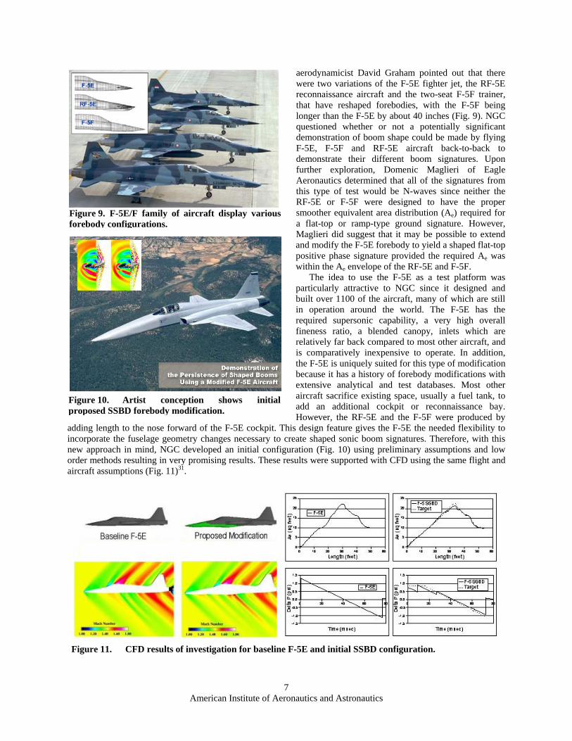
aerodynamicist David Graham pointed out that there were two variations of the F-5E fighter jet, the RF-5E reconnaissance aircraft and the two-seat F-5F trainer, that have reshaped forebodies, with the F-5F being longer than the F-5E by about 40 inches (Fig. 9). NGC questioned whether or not a potentially significant demonstration of boom shape could be made by flying F-5E, F-5F and RF-5E aircraft back-to-back to demonstrate their different boom signatures. Upon further exploration, Domenic Maglieri of Eagle Aeronautics determined that all of the signatures from this type of test would be N-waves since neither the RF-5E or F-5F were designed to have the proper smoother equivalent area distribution (Ae) required for a flat-top or ramp-type ground signature. However, Maglieri did suggest that it may be possible to extend and modify the F-5E forebody to yield a shaped flat-top positive phase signature provided the required Ae was within the Ae envelope of the RF-5E and F-5F.
The idea to use the F-5E as a test platform was particularly attractive to NGC since it designed and built over 1100 of the aircraft, many of which are still in operation around the world. The F-5E has the required supersonic capability, a very high overall fineness ratio, a blended canopy, inlets which are relatively far back compared to most other aircraft, and is comparatively inexpensive to operate. In addition, the F-5E is uniquely suited for this type of modification because it has a history of forebody modifications with extensive analytical and test databases. Most other aircraft sacrifice existing space, usually a fuel tank, to add an additional cockpit or reconnaissance bay. However, the RF-5E and the F-5F were produced by
adding length to the nose forward of the F-5E cockpit. This design feature gives the F-5E the needed flexibility to incorporate the fuselage geometry changes necessary to create shaped sonic boom signatures. Therefore, with this new approach in mind, NGC developed an initial configuration (Fig. 10) using preliminary assumptions and low order methods resulting in very promising results. These results were supported with CFD using the same flight and aircraft assumptions (Fig. 11)31.
Figure 11. CFD results of investigation for baseline F-5E and initial SSBD configuration.
Figure 10. Artist conception shows initial proposed SSBD forebody modification.
Figure 9. F-5E/F family of aircraft display various forebody configurations.

American Institute of Aeronautics and Astronautics
8
With assistance from Domenic Maglieri and Bud Bobbitt of Eagle Aeronautics, NGC presented these findings to Dr. Richard Wlezien, DARPA QSP Program Manager. The briefing document32 of 12 March 2001 addressed the “pros and cons” of providing persistence of a shaped signature to large distances via three proposed methods: 1) flying two NASA Dryden F-18’s in formation – one behind and below the lead F-18; 2) modification of the recoverable Firebee BQM-34E; and 3) modification of an F-5E aircraft. Subsequently, DARPA released a solicitation for the Demonstration of the Persistence of Shaped Sonic Booms33, and NGC provided DARPA with a proposal34 in April 2001.
V. SSBD Program Overview In July 2001, as mentioned above, DARPA awarded the NGC-led team a cooperative agreement to design,
modify and fly an F-5E aircraft with the goal of providing the first-ever in-flight demonstration of an aircraft that has been modified to produce a shaped sonic boom pressure signature that persists through the real atmosphere to the ground (Fig. 12). It is important to note that, in order to validate the shaped boom persistence theory, it was only necessary to show that the positive phase of the signature could be modified. Alteration of the complete sonic boom signature was not essential for this experiment, and would have been extremely expensive and time consuming due to the inherent limitations associated with wholesale modifications of a surrogate aircraft.
A. Loft Development During Phase I of the two-phase SSBD Program,
the design and development of the F-5E modifications were undertaken in several steps, each needing to be successful before proceeding. Initially, linear design tools and CFD were used to develop the proposed new loft for the aircraft. Simultaneously, near-field pressure measurements of the shock waves emanating from an unmodified F-5E were obtained by a specially instrumented NASA Dryden Flight Research Center F-15B aircraft (Fig. 13). The data from this Inlet Spillage Shock Measurement (ISSM) test provided flight-test-derived pressure data to correlate with computation results, especially in the area of inlet spillage shocks. This data was incorporated into the
CFD methodology being used for design, and in fact, helped advance the state-of-the-art analysis for predicting off-body flow field pressure gradients.
NGC formed the SSBD Working Group (SSBDWG) to cooperatively conduct shaping analyses to refine F-5E fuselage modifications in order to produce a persistent shaped waveform. The SSBDWG was composed of key QSP participants, including NASA, Eagle Aeronautics, Wyle Laboratories, Lockheed Martin, Boeing, Gulfstream Aerospace and Raytheon Aircraft. Shaping analysis included application of lower-order methods, particularly NASA Langley’s PBOOM, and NGC’s higher-order CFD methods35 coupled with Wyle Labs’ PCBOOM36 propagation code. In addition to shape refinement, the program also analyzed robustness of the proposed solution, including sensitivity to shape perturbation, Mach number, angle of attack (i.e., weight), and inlet flow. Finally, perturbations on code application including Boeing CFD methods, Lockheed CFD methods and a recently developed 3-D Full-Potential-Propagation-Code37 were run to help verify consistent interpretation.
Figure 12. SSBD Program objective was to achieve a “flat-top” signature under actual flight conditions.
Figure 13. Inlet spillage shock measurement of baseline F-5E with NASA F-15B probe aircraft.

American Institute of Aeronautics and Astronautics
9
The existing NGC 0.05-scale, high-speed F-5E wind tunnel model, was modified to match the shape chosen by SSBDWG consensus, and was tested in the NASA Glenn 8’ x 6’ supersonic wind tunnel (Fig. 14). The sonic boom pressure measurements obtained in the tunnel compared favorably to the computational predictions, thereby validating code application and interpretation, and generating additional confidence in the chosen solution (Fig. 15).
Phase I culminated with a Preliminary Design Review (PDR) where the results of the shaped boom wind tunnel
test were presented along with the computational predictions (Fig. 16). Based on these results, concurrence was reached on the final external loft for the F-5 SSBD aircraft. In addition, recommendations were made for the most cost-effective approach for Phase II tasks, including the manufacturing effort, flight test execution, and data measurement plans.
B. Vehicle Design, Modification and Test Phase II consisted of safety-of-flight wind tunnel testing, detailed design and manufacture of the F-5E
modification hardware, aircraft acquisition and modification, flight test and data analysis.
Figure 14. SSBD 5% model in NASA Glenn’s 8’ x 6’ supersonic wind tunnel for boom validation.
-0.06
-0.05
-0.04
-0.03
-0.02
-0.01
0.00
0.01
0.02
0.03
0.04
35 40 45 50 55 60 65 70 75Along Track (Model) - inches
∆P l
ocal /
P loc
al fr
eest
ream
Euler - 24b WTM-2 @ MFR = 0.76
24b4 WT Data @ MFR = 0.76 - 0.80 - Rdg. 143 (P3)
24b4 WT Data @ MFR = 0.76 - 0.80 - Rdg. 157 (P4)
ReflectedShock
Figure 15. Wind tunnel boom data compares favorably with CFD predictions.
F5SBD-24B, 1.40M, Flt Alt = 30kft, 12500 lbs, 0.74 MFR, NFBOOM-ANET, H sig = 0 ft,
Reflection Factor = 1.9
-1.5
-1.0
-0.5
0.0
0.5
1.0
1.5
2.0
0.00 0.02 0.04 0.06 0.08
Time (sec)
Del
ta P
ress
ure
(psf
)
From h/L = 2.0
F5SBD-24B, 1.40M, Flt Alt = 30kft, 12500 lbs, 0.74 MFR NFBOOM-ANET, H sig = 29,000 ft
-5.0-4.0-3.0-2.0-1.00.01.02.03.04.05.0
0.00 0.01 0.02 0.03 0.04 0.05 0.06
Time (sec)
Del
ta P
ress
ure
(psf
)
From h/L=2.0
F-5 SSBD-24BM=1.40, H=30K Ft, W=12500 lbs
MFR=0.74, Non-Linear (CFD) Analysis
Ground
H=29,000 ft
Figure 16. SSBD24b configuration as analyzed by SSBDWG at end of Phase I.

American Institute of Aeronautics and Astronautics
10
The ground testing included low-speed and high-speed force-and-moment wind tunnel testing to verify that the modified aircraft met all safety-of-flight criteria (Figs. 17-18). A new 0.10-scale, low speed model was designed and built to support this activity and was tested in NGC’s 7’ x 10’ tunnel. In addition, the 0.05-scale high-speed wind tunnel model using during the Phase I boom testing was modified to support the high-speed safety-of-flight test, which was performed in the Arnold Engineering Development Center (AEDC) 4-foot Wind Tunnel Facility at Arnold AFB, Tennessee. Both of these tests were designed to obtain force and moment effects of the modified SSBD nose section. Baseline F-5E configuration measurements were also obtained in both tests and compared to existing historical databases to ensure accuracy and repeatability.
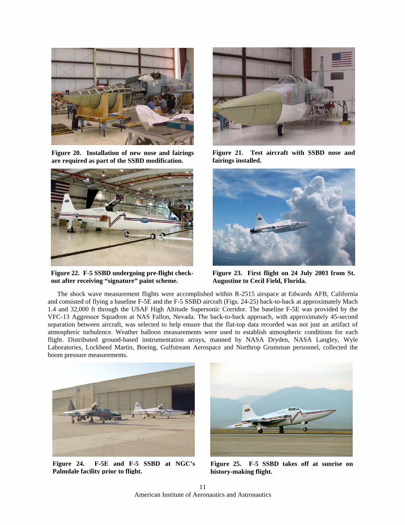
The F-5E aircraft shown in Figure 19 was made available by the U.S. Navy under a Cooperative Research and Development Agreement (CRADA) with Northrop Grumman. The new components required for the specially shaped structure were designed, fabricated, and partially assembled at NGC’s El Segundo, California facility. Final assembly and installation of the hardware took place at NGC’s St. Augustine, Florida facility where the company performs F-5 depot work for the U.S. Navy. The modifications consisted of a new longer nose and the addition of aluminum frames, bulkheads and composite skin panels attached to the underside of the fuselage to create the required shape (Figs. 20-22). An instrumentation and telemetry package was also added to support flight test requirements. Naval Air Systems Command (NAVAIR) conducted a thorough
review of both the modification design and the flight test plan, and issued a flight clearance to cover the operation of the F-5 SSBD aircraft. A Flight Readiness Review (FRR) was successfully completed prior to flight testing in order to ensure that all quality assurance and safety-of-flight concerns were addressed, reviewed, and approved.
The SSBD flight test program was divided into two phases: Envelope Expansion Tests and Sonic Boom Data Collection Tests. An initial series of subsonic envelope expansion flights were completed in Florida (Fig. 23), followed by a M1.1 envelope expansion flight. The aircraft was then flown to California for the remainder of the supersonic envelope expansion flights. During the airworthiness/envelope expansion testing, the aircraft was based out of St. Augustine and Cecil Field, Florida, and Palmdale, California, with the actual flight tests occurring in government test ranges. Boeing provided a T-38 aircraft for chase support during the Florida-based testing, as well as an SSBD ferry flight escort to the west coast. A NASA Dryden F-18 supported the envelope expansion testing in California. The SSBD aircraft successfully completed eight functional checkout, calibration, and envelope expansion flights. Although the supersonic envelope expansion flights were not designed to support shaped sonic boom data collection, they proved to be invaluable as trial runs for the flight crews, the flight test ground controllers and for the ground data crews.
Figure 17. Low-speed model undergoing tests in NGC’s 7’ x 10’ wind tunnel.
Figure 19. Navy F-5E at NGC’s St. Augustine facility prior to start of SSBD modification effort.
Figure 18. High-speed model installed in AEDC’s 4’ supersonic wind tunnel.
American Institute of Aeronautics and Astronautics
11
Figure 20. Installation of new nose and fairings are required as part of the SSBD modification.
Figure 23. First flight on 24 July 2003 from St. Augustine to Cecil Field, Florida.
Figure 24. F-5E and F-5 SSBD at NGC’s Palmdale facility prior to flight.
Figure 25. F-5 SSBD takes off at sunrise on history-making flight.
The shock wave measurement flights were accomplished within R-2515 airspace at Edwards AFB, California and consisted of flying a baseline F-5E and the F-5 SSBD aircraft (Figs. 24-25) back-to-back at approximately Mach 1.4 and 32,000 ft through the USAF High Altitude Supersonic Corridor. The baseline F-5E was provided by the VFC-13 Aggressor Squadron at NAS Fallon, Nevada. The back-to-back approach, with approximately 45-second separation between aircraft, was selected to help ensure that the flat-top data recorded was not just an artifact of atmospheric turbulence. Weather balloon measurements were used to establish atmospheric conditions for each flight. Distributed ground-based instrumentation arrays, manned by NASA Dryden, NASA Langley, Wyle Laboratories, Lockheed Martin, Boeing, Gulfstream Aerospace and Northrop Grumman personnel, collected the boom pressure measurements.
Figure 21. Test aircraft with SSBD nose and fairings installed.
Figure 22. F-5 SSBD undergoing pre-flight check-out after receiving “signature” paint scheme.

American Institute of Aeronautics and Astronautics
12
Signatures Recorded During SSBD Back-to-Back Data Flights in
the Edwards AFB Supersonic Flight
Corridor Early Morning
Flight Conditions: Mach 1.36+,
Altitude 32,000 ft
Shock Thickening AdjustedGround Boom Signature Comparisons
-1.4
-1.2
-1.0
-0.8
-0.6
-0.4
-0.2
0.0
0.2
0.4
0.6
0.8
1.0
1.2
1.4
0 10 20 30 40 50 60 70 80 90 100Time - msec
∆P
- psf
SBD-24b @ 12,700 lbs.
F-5E @ 11,200 lbs.
Tanh 1/P ModificationM = 1.40h = 32 kft.
F-5SSBDF-5E
Design Mach 1.4
Figure 26. Actual ground signatures and CFD predictions for F-5 SSBD/F-5E back-to-back flight test on 27 August 2003.
A total of five SSBD data collection flights were conducted – three back-to-back with the Navy F-5E, and two using the NASA F-15B aircraft equipped with a pressure measurement probe which provided an in-flight assessment of the near field shocks emanating from the F-5 SSBD aircraft. The in-flight measurements provided data for comparison to the computation methods used to design and analyze the aircraft modifications, further advancing the understanding of how to exploit aircraft shaping for reducing the noise of sonic booms, and providing further validation of the computational techniques employed38. All data recorded supports the definitive conclusion that the shaped boom persisted to the ground. The repeatable back-to-back ground measurements provided “bottom line” validation that aircraft shaping can produce a shaped sonic boom that persists in the far field (Fig. 26). Furthermore, the modifications themselves did not produce adverse performance or safety effects, which supports the theory’s applicability and robustness to practical aircraft design.
VI. SSBE Program Overview The SSBD data flights were conducted in August of 2003. At that time, the usual high ambient temperature
conditions were prevalent in the test range. The test altitude temperature of 17 deg. C over standard day, exceeded the design envelop of the SSBD aircraft. The aircraft could only reach the lower limit of the design Mach range, and flight endurance was limited. At the end of the DARPA-sponsored activity, NASA decided to pursue a second flight series to collect a more extensive set of shaped sonic boom signature data. The SSBDWG was kept intact, and NGC was tasked to lead the planning and execution of the second flight series. NASA Dryden Flight Research Center led the development of the data recording for what became known as the Shaped Sonic Boom Experiment (SSBE).
The SSBE had three objectives. First was to collect ground and flight sonic boom pressure recordings of the SSBD aircraft at both design and off-design flight conditions. The second objective was an initial quantification of the effects of turbulence on the shaped boom signature, and the third was to attempt to create and record a focus boom with the SSBD aircraft.
Test planning and execution took place at a very rapid pace, owing to a requirement to return the SSBD aircraft to the Navy by the end of January 2004. A boom sensor array was designed for a location near the Edwards North Base Runway. The new array consisted of 42 sensors, most of which were arranged in a 12,500 ft long line under the proposed flight track. Other sensors were located 1mile north and south of the track. Aircraft assets were identified, and flight plans formulated for a back-to-back and in-flight pressure probing. In addition, an agreement was reached whereby the USAF Test Pilot School would fly an instrumented glider below the flight track of the SSBD and baseline F-5s to recorded boom signatures above the earth’s turbulent boundary layer.
The SSBE experiment was successfully conducted in January of 2004. In all, 21 data flights were conducted, and all test objectives were met or exceeded Eight of these flights were conducted back to back with an unmodified F-

American Institute of Aeronautics and Astronautics
13
5E, again provided by the VFC-13 Aggressor Squadron. Four probing formation flights were conducted with the NASA F-15B, and the glider was airborne on 13 of the flights. Over 1300 boom signature recordings were made, and 45 probe data sets were recorded. The data showed excellent agreement with theoretical predictions, and indicated that a shaped sonic boom signature will persist to the ground under a variety of flight and atmospheric conditions. On two of the flights a push over maneuver was performed to create a focus boom. In both attempts, the focus event was successfully recorded on the linear sensor array.
VII. Concluding Remarks The SSBD and SSBE Programs positively demonstrated that the intensity of the sonic boom can be reduced
through aircraft shaping. The shaped sonic boom has been shown to persist to the ground under a variety of flight and atmospheric conditions. The vast amount of data collected during these tests will be invaluable to future supersonic aircraft designs in that it will allow designers to go forward with confidence in the ability to predict, and thereby control, sonic booms. Details of this data are contained in companion papers31, 38, 39, 40, 41, 42, 43 & 44.
The SSBD and SSBE Programs were extremely successful due to the excellent cooperation between all companies and government agencies involved. In fact, the teamwork was so exemplary that the entire group was honored with the NASA Turning Goals Into Reality Partnership Award for 2004. In addition, the program achievements were considered to be so significant that AIAA bestowed its prestigious 2004 Aircraft Design Award on the NGC design team.
As soon as space is available, the U.S. Navy plans to induct the F-5 SSBD aircraft into the National Museum of Naval Aviation in Pensacola, Florida. In the meantime, it is on loan to the Valiant Air Command Warbird Museum in Titusville, Florida near the Kennedy Space Center.
References 1Jones, L. B., “Lower Bounds for Sonic Bangs.” Journal of the Royal Aeronautical Society, Vol. 65, June 1961, pp. 433-436. 2Carlson, H. W., “The Lower Bound of Attainable Sonic-Boom Overpressure and Design Methods of Approaching This
Limit.” NASA TN-D-1494, Oct. 1962. 3Whitham, C. B., “On the Propagation of Weak Shock Waves”, Journal of Fluid Mechanics, Vol. 1, pt. 3, Sept. 1956. 4Carlson, H. W., “Influence of Airplane Configuration on Sonic Boom Characteristics,” J. Aircraft 1, No. 2, 82-86, 1964. 5McLean, F. E., “Some Nonasymptotic Effects on the Sonic Boom of Large Airplanes,” NASA TN-D-2877, June 1965. 6McLean, F. E. and Shrout, B. L., “Design Methods for Minimization Of Sonic Boom Pressure-Field Disturbances,” Journal
of the Acoustical Society of America, 39, 5, Part 2, 1966, pp. S19-S25. 7Ferri, A. and Ismail, A., “Report on Sonic Boom Studies,” Pt. 1, Analysis of Configurations. NASA SP-180, 1968, pp. 73-
88. 8Ferri, A., “Airplane Configurations for Low Sonic Boom,” NASA SP-255, Oct. 1970, pp. 255-275. 9Hayes, W. D., Haefili, R. C., and Kulsvud, H. E., “Sonic Boom Propagation in a Stratified Atmosphere, With Computer
Program,” NASA CR-1299, 1969. 10George, A. R., “Lower Bounds for Sonic Booms in the Mid-Field,” AIAA Journal, Vol. 7, No. 8, Aug. 1969, pp. 1542-
1545. 11George, A. R. and Seebass, R., “Sonic Boom Minimization Including Both Front and Rear Shocks,” AIAA Journal, Vol. 9,
No. 10, Oct. 1971, pp. 2091-2093. 12Kane, Edward J., “A Study to Determine the Feasibility of a Low Sonic Boom Supersonic Transport,” NASA CR-2332,
Dec. 1972. 13Carlson, H. W., Barger, R. W., and Mack, R. J., “Application of Sonic Boom Minimization Concepts in Supersonic
Transport Design,” NASA TN-D-7218, 1973. 14Niedzwiecki, A., and Ribner, H. S., “Subjective Loudness and Annoyance of Filtered N-wave Sonic Booms,” Journal of
the Acoustical Society of America, Vol. 16, No. 3, 1974, pp. 705-702 15Darden, C. M., “Minimization of Sonic Boom Parameters in Real and Isothermal Atmospheres,” NASA TN-D-7842, 1975. 16Darden, C. M., “Sonic Boom Minimization With Nose Bluntness Relaxation,” NASA TP 1348, 1979. 17Mack, R. J., and Darden, C. M., “A Wind-Tunnel Investigation of the Validity of a Sonic Boom Minimization Concept,”
NASA TP-1421, 1979. 18Darden, C. M., Clemans, A., Hayes, W. D., George, A. R., and Pierce, A. D., “Status of Sonic Boom Methodology and
Understanding,” NASA CR-3027, 1988. 19Leatherwood, J. D., and Sullivan, Brenda M., “Laboratory Studies of Effects of Boom Shaping on Subjective Loudness and
Acceptability,” NASA TP-3269, 1992. 20Shepherd, K. P., and Sullivan, B. M., “A Loudness Calculation Procedure Applied to Shaped Sonic Booms,” NASA TP-
3134, Nov. 1991. 21Darden, C. M., “High Speed Research Sonic Boom,” Vol. II, NASA CP 3173, Feb. 1992. 22McCurdy, D. A., “High-Speed Research: 1994 Sonic Boom Workshop; Configuration Design, Analysis and Testing,”
NASA CP 1999-209699, June 1994.

American Institute of Aeronautics and Astronautics
14
23Maglieri, D. J., Sothcott, V. E., and Keefer, T. N., Jr., “Feasibility Study on Conducting Overflight Measurements of Shaped Sonic Boom Signatures Using the Firebee BQM-34E RPV,” NASA CR 189715, Feb. 1993.
24Stansbery, E. G., Baize, D. G., and Maglieri, D. J., “In-Flight Technique for Acquiring Mid- and Far-Field Sonic Boom Signatures,” NASA CP 1999-209699, Oct. 1994, pp. 249-268.
25Lux, D., Ehernberger, L. J., Moes, T. R., and Haering, E. A., “Low-Boom SR-71 Modified Signature Demonstration Program,” NASA TM 104307, Oct. 1994, pp. 237-248.
26Morgenstern, J. M., Bruns, D. B., and Camacho, P. P., “SR71A Reduced Sonic Boom Modification Design,” NASA CP 1999-209699, Oct. 1994, pp. 149-218.
27Fouladi, K., “CFD Predictions of Sonic Boom Characteristics for Unmodified and Modified SR-71 Configurations,” NASA CP 1999-209699, Oct. 1994, pp. 219-236.
28Haering, E. A., Jr., Ehernberger, L. J., and Whitmore, Stephen A., “Preliminary Airborne Measurements for the SR-71 Sonic Boom Propagation Experiment,” NASA TM TO4307, Sept. 1995.
29Wlezien, R., and Veitch, L., “Quiet Supersonic Platform Program,” AIAA 2002-0143, Jan. 2002. 30Maglieri, D. J., Bobbitt, P. J., and Henderson, H. R., “Proposed Flight Test Program to Demonstrate Persistence of Shaped
Sonic Boom signatures using Firebee BQM 34E RPV,” Eagle Aeronautics, Inc. response to DARPA RFI-Advanced Supersonic Program, April 19, 2000.
31Meredith, K. B, Dahlin, J. H., Graham, D. H., Malone, M. B., Haering, E. A., Jr., Page, J. A., and Plotkin, K. J., “Computational Fluid Dynamics Comparison and Flight Test Measurement of F-5E Off-Body Pressures”, AIAA-2005-0006, 43rd AIAA Aerospace Sciences Meeting and Exhibit, January 10-13, 2005, Reno, NV.
32Maglieri, D. J. and Bobbitt P. J., “Overview of Flight Demonstrations to Prove Persistence of Shaped Sonic Boom Signatures,” Eagle Aeronautics, Inc. Briefing Document to Dr. Richard Wlezien of DARPA for Northrop Grumman, March 12, 2001.
33DARPA, “Demonstration of the Persistence of Shaped Sonic Booms” solicitation, Apr. 2001. 34Northrop Grumman, “Demonstration of the Persistence of Shaped Booms Using a Modified F-5E Aircraft,” Prepared for
DARPA, Apr. 2001. 35Malone, M. B., “Turbulence Model Evaluation for Free Shear Dominated Flows,” AIAA-1996-2038, 27th Fluid Dynamics
Conference, New Orleans, LA, June 17-20, 1996. 36Plotkin, K. J., and Grandi, F., “Computer Models for Sonic Boom Analysis: PCBoom4, CABoom, BooMap, CORBoom,”
Wyle Report WR 02-11, June 2002. 37Kandil, O. A., Yang, Z., and Bobbitt, P. J., “Prediction of Sonic Boom Signature Using Euler-Full-Potential CFD with Grid
Adaptation and Shock Fitting,” AIAA CP 2002-2543, June 2002. 38Haering, E. A., Jr., Murray, J. E., Purifoy, D. D., Graham, D. H., Meredith, K. B., Ashburn, C. E., and Stucky, M., Lt. Col.,
“Airborne Shaped Sonic Boom Demonstration Pressure Measurements with Computational Fluid Dynamics Comparisons,” AIAA-2005-0009, 43rd AIAA Aerospace Sciences Meeting and Exhibit, January 10-13, 2005, Reno, NV.
39Graham, D. H., Dahlin, J. H., Page, J. A., Plotkin, K. J., and Coen, P. G., “Wind Tunnel Validation of Shaped Sonic Boom Demonstration Aircraft Design,” AIAA-2005-0007, 43rd AIAA Aerospace Sciences Meeting and Exhibit, January 10-13, 2005, Reno, NV.
40Graham, D. H., Dahlin, J. H., Meredith, K. B., and Vadnais, J., “Aerodynamic Design of Shaped Sonic Boom Demonstration Aircraft,” AIAA-2005-0008, 43rd AIAA Aerospace Sciences Meeting and Exhibit, January 10-13, 2005, Reno, NV.
41Plotkin, K., Haering, E., Murray, J., Maglieri, D., Salamone, J., Sullivan, B., and Schein, D., “Ground Data Collection of Shaped Sonic Boom Demonstration Aircraft Pressure Signatures,” AIAA-2005-0010, 43rd AIAA Aerospace Sciences Meeting and Exhibit, January 10-13, 2005, Reno, NV.
42Plotkin, K., Martin, M. L., Maglieri, D., Haering, E., and Murray, J., “Pushover Focus Booms From the Shaped Sonic Boom Demonstrator,” AIAA-2005-0011, 43rd AIAA Aerospace Sciences Meeting and Exhibit, January 10-13, 2005, Reno, NV.
43Morgenstern, J. M., Arslan, A., Pilon, A., Lyman, V., and Vadyak, J., “F-5 Shaped Sonic Boom Demonstrator’s Persistence of Boom Shaping Reduction Through Turbulence,” AIAA-2005-0012, 43rd AIAA Aerospace Sciences Meeting and Exhibit, January 10-13, 2005, Reno, NV.
44Kandil, O. A., and Bobbitt, P. J., “Comparison of Full-Potential-Equation, Propagation-Code Computations with Measurements from the F-5 Shaped Sonic Boom Experiment Program,” AIAA-2005-0013, 43rd AIAA Aerospace Sciences Meeting and Exhibit, January 10-13, 2005, Reno, NV.