Original STS-4 press kit cover artwork - Johnson - NASA STS-4 press kit cover artwork . ... fly the...
79
Edited by Richard W. Orloff, 01/2001/Page 1 Original STS-4 press kit cover artwork
Transcript of Original STS-4 press kit cover artwork - Johnson - NASA STS-4 press kit cover artwork . ... fly the...
Edited by Richard W. Orloff, 01/2001/Page 1
Original STS-4 press kit cover artwork
Edited by Richard W. Orloff, 01/2001/Page 2
NATIONAL AERONAUTICS AND SPACE ADMINISTRATION
SPACE SHUTTLE MISSION STS-4
PRESS KIT JUNE 1982
FOURTH SPACE SHUTTLE ORBITAL FLIGHT TEST (OFT-4)
Edited by Richard W. Orloff, 01/2001/Page 3
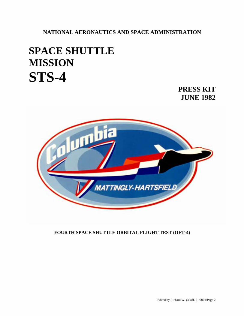
STS-4 INSIGNIA S82-29695 – The STS-4 insignia shows the Columbia trailing our nation's colors in the shape of Columbia's flight number, 4, representing the fourth and final flight of the highly successful flight test phase. Columbia then streaks on into the future, entering the exciting operation phase. The NASA insignia design for space shuttle flights is reserved for use by the astronauts and for other official use as the NASA Administrator may authorize. Public availability has been approved only in the form of illustrations by the various news media. When and if there is any change in this policy, which we do not anticipate, it will be publicly announced. PHOTO CREDIT: NASA or National Aeronautics and Space Administration.
Edited by Richard W. Orloff, 01/2001/Page 4
RELEASE NO. 82-94 June 1982
CONTENTS
GENERAL RELEASE 6 SCHEDULED PRESS BRIEFINGS 9 NASA SELECT TELEVISION SCHEDULE FOR STS-4 10 STS-4 OBJECTIVES: PROVING OPERATIONAL READINESS 12 LAUNCH PREPARATIONS. COUNTDOWN AND LIFTOFF 14 MAJOR COUNTDOWN MILESTONES 17 LAUNCH WINDOW 18 STS-4 FLIGHT SEQUENCE OF EVENTS 18 GUIDE TO USING THE FLIGHT PLAN 19 LANDING AND POSTLANDING OPERATIONS 33 IF THINGS GO WRONG 40 STS-4: COLUMBIA'S FINAL SHAKEDOWN FLIGHT 41 STS-4 EXPERIMENTS 42 GETAWAY SPECIAL 53 SHUTTLE STUDENT INVOLVEMENT PROJECT 58 ORBITER EXPERIMENTS PROGRAM 59 ORBITER'S ROBOT "ARM" 64 HUNTSVILLE OPERATIONS SUPPORT CENTER 65 SPACEFLIGHT TRACKING AND DATA NETWORK (STDN) 66 NASA TRACKING STATIONS 67 STS-4 FREQUENCIES 67 SHUTTLE STANDARD OFT MENU 69 CREW BIOGRAPHIES 70 SPACE SHUTTLE PROGRAM MANAGEMENT 74 ABBREVIATIONS/ACRONYMS 76
Edited by Richard W. Orloff, 01/2001/Page 5
STS-4 MISSION SUMMARY The flight crew for STS-4 is Commander Thomas K. (Ken) Mattingly II, 46, and Pilot Henry W. Hartsfield Jr. 48. Columbia will be launched into a circular orbit above the Earth with an inclination to the equator of 28.5 degrees. Two burns of the orbital maneuvering engines will place Columbia in a 241 kilometer (130 nautical mile) circular orbit. A third and fourth burn of the Orbital Maneuvering System engines on the fourth revolution will place Columbia in a circular orbit 296 km (160 nm) above the Earth. The launch window for STS-4 will be for 4 hours and 24 minutes. The window will open at 11 a.m. EDT and extend until 3:24 p.m. for a nominal late June launch. The end of the window is restricted to a trans-Atlantic abort into Dakar, Senegal no later than l5 minutes after sunset. Columbia will operate in several different attitudes during the 168-hour flight -- "barbecue" fashion, or passive thermal control; top to the Sun; tail to Sun; and belly to Sun. To stabilize its systems prior to reentry, Columbia will fly the final 10 hours of the mission in the passive thermal control attitude. An experiment that marks the first use of the Space Shuttle by a commercial concern tops the list of non-government payloads scheduled to be carried into space on the fourth Shuttle flight. The Continuous Flow Electrophoresis System (CFES) experiment which will separate biological materials in a fluid according to their surface electrical charge, will make its maiden flight on STS-4. The experiment is part of a NASA/McDonnell Douglas Astronautics Co. "joint endeavor agreement" to conduct research in space.
Edited by Richard W. Orloff, 01/2001/Page 6
RELEASE NO. 82-94 June 1982 Jim Kukowski Headquarters, Washington, D.C. (Phone: 202/755-3090) Dick Young Kennedy Space Center, Fla. (Phone: 305/867-2468) Terry White Johnson Space Center, Houston, Texas (Phone: 713/483-5111) John Taylor Marshall Space Flight Center, Huntsville, Ala. (Phone: 205/453-0034 )
COLUMBIA UNDERGOES FINAL SHAKEDOWN DURING SEVEN-DAY STS-4 MISSION
The fourth and final development flight of the Space Shuttle is scheduled for launch June 27, 1982, from Complex 39's Pad A at NASA's Kennedy Space Center in Florida. Columbia's fourth mission is scheduled for seven days and will complete the shakedown of the Shuttle orbiter and booster systems. The nation's Space Transportation System becomes operational with flight five, now scheduled for November. Among top priorities listed for STS-4 are the continued studies of the effects of long-term thermal extremes on the orbiter subsystems and a survey of orbiter induced contamination on the Payload bay. The flight crew for STS-4 is Commander Thomas K. (Ken) Mattingly II, 46, and Pilot Henry W. Hartsfield Jr., 48. Columbia will be launched into a circular orbit above the Earth with an inclination to the equator of 28.5 degrees. Two burns of the orbital maneuvering engines will place Columbia in (130 nautical mile) circular orbit. A third and a 241 kilometer fourth burn of the Orbital Maneuvering System engines on the fourth revolution will place Columbia in a circular orbit 296 km (160 nm) above the Earth. The launch window for STS-4 will be for 4 hours and 24 minutes. The window will open at 11 a.m. EDT and extend until 3:24 p.m. for a nominal late June launch. The end of the window is restricted to a trans-Atlantic abort into Dakar, Senegal no later than 15 minutes after sunset. Columbia will operate in several different attitudes during the 168-hour flight -- "barbecue" fashion, or passive thermal control; top to the Sun; tail to Sun; and belly to Sun. To stabilize its systems prior to reentry, Columbia will fly the final 10 hours of the mission in the passive thermal control attitude. An experiment that marks the first use of the Space Shuttle by a commercial concern tops the list of non-government payloads scheduled to be carried into space on the fourth Shuttle flight. The Continuous Flow Electrophoresis System (CFES) experiment which will separate biological materials in a fluid according to their surface electrical charge, will make its maiden flight on STS-4. The experiment is part of a NASA/McDonnell Douglas Astronautics Co. "joint endeavor agreement" to conduct research in space.
Edited by Richard W. Orloff, 01/2001/Page 7
The electrophoresis process has a high probability of being able to separate substances that cannot be separated in sufficient quantities or purity on Earth into commercially attractive substances which may be useful in the diagnosis, treatment or prevention of human or animal diseases. The experiment involves separation of proteins and other natural biological matter. The first operational "Getaway Special" will fly on STS-4. Inside the 61-by-91-centimeter (24-by-36-inch) canister will be nine experiments that range from algae and duckweed growth in space to fruit fly and brine shrimp genetic studies. The Getaway Special was purchased by R. Gilbert Moore, a manager at the Thiokol Corp. in Ogden, Utah. He subsequently donated it to Utah State University where it is being used in a program for student constructed experiments. Several experiments will be making their third and fourth flights aboard the Shuttle. Among those carried on previous missions are the Development Flight Instrumentation Package, Aerodynamic Coefficient Identification Package and several orbiter experiments such as the catalytic surface effects and tile gap heating effects. The Induced Environmental Contamination Monitor will be making its third flight into space on STS-4. The desk-sized package will measure the contaminants within and around the cargo bay which may affect scientific experiments or other cargo on future flights. The mechanical remote manipulator arm will get its stiffest test to date. The robot arm will lift the 363-kilogram (800 pound) contamination monitor up out of the cargo bay and move it to various locations around the bay area to provide a more complete survey of the payload bay environment. A Department of Defense Payload, DOD 82-1, shares the payload bay. Other experiments, both making their second trip into space, include the Nighttime/Daytime Optical Survey of Lightning, flown aboard STS-2 but which produced limited results because of the shortened mission, and the Monodisperse Latex Reactor, an STS-3 passenger, will make a repeat performance aboard Columbia. The lightning survey experiment is designed to record motion pictures and photo cell readings of lightning and thunderstorms as seen from orbit. These techniques may be adaptable in the development of sensors to identify severe weather situations from future meteorological satellites. The second flight of the Monodisperse Latex Reactor is designed to test the feasibility of making large size, monodisperse (same size), polystyrene latex micro-spheres using the products of the STS-3 mission as seed particles. The latex spheres are used in calibration of scientific and industrial equipment and have potential medical and research applications. STS-3 carried the first student-developed experiment onboard, and NASA will continue its Shuttle Student Involvement Project on STS-4 with two more student experiments. They are: "The effect of prolonged space travel on levels of trivalent chromium in the body" - - proposed by Karla R. Hauersperger, a senior at East Mecklenburg High School in Charlotte, N.C. "The effect of exercise, diet and zero gravity on lipoprotein profiles" - - proposed by Amy M. Kusske, a graduate of Hill Junior High School in Long Beach, Calif. These two studies involve the physiological effects of space travel on the human body. Neither experiment will require any hardware. Instead, the astronauts will fill out data cards about their exercise on the treadmill, and their daily food intake. The mission is scheduled to last 168 hours with 112 orbits around the Earth.
Edited by Richard W. Orloff, 01/2001/Page 8
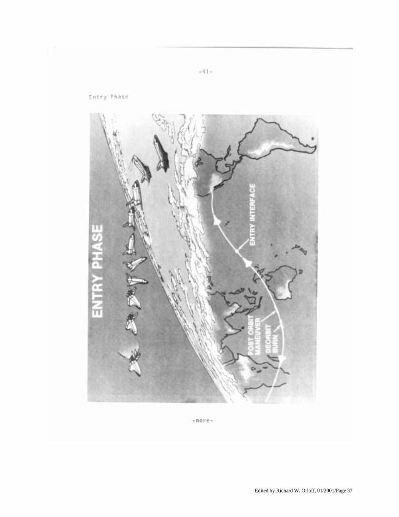
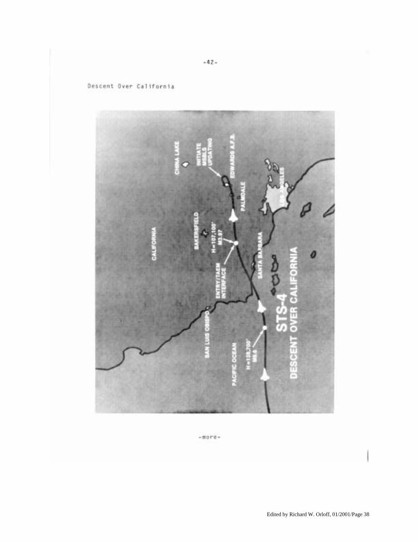
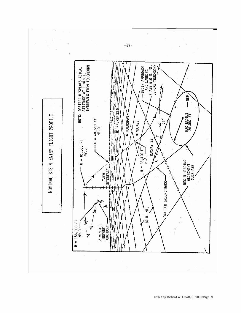
Mattingly and Hartsfield will follow the same course in returning from orbit as did early STS crews: retrofire over the Indian Ocean, atmospheric entry over the western Pacific Ocean, and then a transition to aerodynamic controls in the atmosphere as an landing an aircraft. NASA officials have made the cross-wind landing tests a highly desirable flight objective on STS-4. Columbia will land at Edwards Air Force Base, Calif., on Runway 17, a dry lakebed runway, or on Runway 22, a hard surface runway, if acceptable cross-wind conditions are not available. The 3-mile long paved runway at Kennedy Space Center will be the prime backup landing site. Columbia will be guided to its landing site by a microwave scanning beam landing system at the landing site. As the orbiter descends, Mattingly will put the craft through rolls and other maneuvers to test how the spacecraft handles under stress. The craft will remain in the automatic mode through 762 meters (2,500 feet) and will be flown to landing and controlled through rollout by the crew.
(END OF GENERAL RELEASE; BACKGROUND INFORMATION FOLLOWS.)
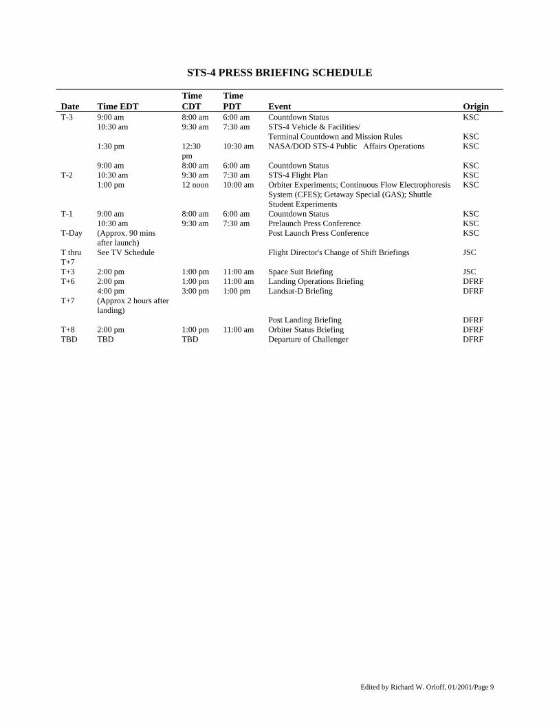
Edited by Richard W. Orloff, 01/2001/Page 9
STS-4 PRESS BRIEFING SCHEDULE
Date
Time EDT
Time CDT
Time PDT
Event
Origin
T-3 9:00 am 8:00 am 6:00 am Countdown Status KSC 10:30 am 9:30 am 7:30 am STS-4 Vehicle & Facilities/
Terminal Countdown and Mission Rules KSC
1:30 pm 12:30 pm
10:30 am NASA/DOD STS-4 Public Affairs Operations KSC
9:00 am 8:00 am 6:00 am Countdown Status KSC T-2 10:30 am 9:30 am 7:30 am STS-4 Flight Plan KSC 1:00 pm 12 noon 10:00 am Orbiter Experiments; Continuous Flow Electrophoresis
System (CFES); Getaway Special (GAS); Shuttle Student Experiments
KSC
T-1 9:00 am 8:00 am 6:00 am Countdown Status KSC 10:30 am 9:30 am 7:30 am Prelaunch Press Conference KSC T-Day (Approx. 90 mins
after launch) Post Launch Press Conference KSC
T thru T+7
See TV Schedule Flight Director's Change of Shift Briefings JSC
T+3 2:00 pm 1:00 pm 11:00 am Space Suit Briefing JSC T+6 2:00 pm 1:00 pm 11:00 am Landing Operations Briefing DFRF 4:00 pm 3:00 pm 1:00 pm Landsat-D Briefing DFRF T+7 (Approx 2 hours after
landing)
Post Landing Briefing DFRF T+8 2:00 pm 1:00 pm 11:00 am Orbiter Status Briefing DFRF TBD TBD TBD Departure of Challenger DFRF
Edited by Richard W. Orloff, 01/2001/Page 10
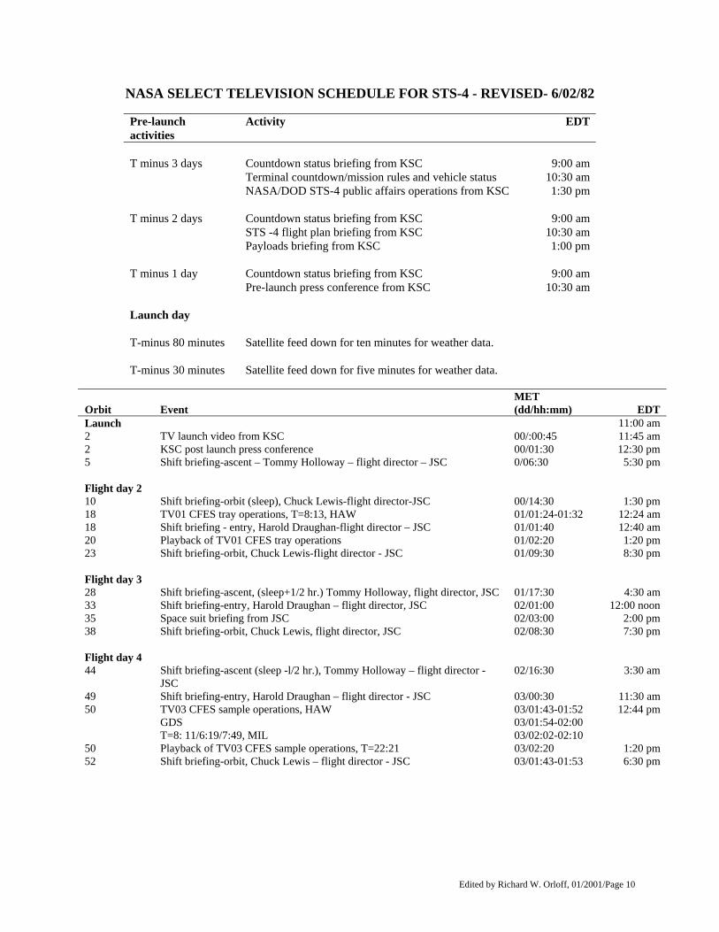
NASA SELECT TELEVISION SCHEDULE FOR STS-4 - REVISED- 6/02/82
Pre-launch activities
Activity EDT
T minus 3 days Countdown status briefing from KSC 9:00 am Terminal countdown/mission rules and vehicle status 10:30 am NASA/DOD STS-4 public affairs operations from KSC 1:30 pm T minus 2 days Countdown status briefing from KSC 9:00 am STS -4 flight plan briefing from KSC 10:30 am Payloads briefing from KSC 1:00 pm T minus 1 day Countdown status briefing from KSC 9:00 am Pre-launch press conference from KSC 10:30 am Launch day T-minus 80 minutes Satellite feed down for ten minutes for weather data. T-minus 30 minutes Satellite feed down for five minutes for weather data.
Orbit
Event
MET (dd/hh:mm)
EDT
Launch 11:00 am 2 TV launch video from KSC 00/:00:45 11:45 am 2 KSC post launch press conference 00/01:30 12:30 pm 5 Shift briefing-ascent – Tommy Holloway – flight director – JSC 0/06:30 5:30 pm Flight day 2 10 Shift briefing-orbit (sleep), Chuck Lewis-flight director-JSC 00/14:30 1:30 pm 18 TV01 CFES tray operations, T=8:13, HAW 01/01:24-01:32 12:24 am 18 Shift briefing - entry, Harold Draughan-flight director – JSC 01/01:40 12:40 am 20 Playback of TV01 CFES tray operations 01/02:20 1:20 pm 23 Shift briefing-orbit, Chuck Lewis-flight director - JSC 01/09:30 8:30 pm Flight day 3 28 Shift briefing-ascent, (sleep+1/2 hr.) Tommy Holloway, flight director, JSC 01/17:30 4:30 am 33 Shift briefing-entry, Harold Draughan – flight director, JSC 02/01:00 12:00 noon 35 Space suit briefing from JSC 02/03:00 2:00 pm 38 Shift briefing-orbit, Chuck Lewis, flight director, JSC 02/08:30 7:30 pm Flight day 4 44 Shift briefing-ascent (sleep -l/2 hr.), Tommy Holloway – flight director -
JSC 02/16:30 3:30 am
49 Shift briefing-entry, Harold Draughan – flight director - JSC 03/00:30 11:30 am 50 TV03 CFES sample operations, HAW 03/01:43-01:52 12:44 pm GDS 03/01:54-02:00 T=8: 11/6:19/7:49, MIL 03/02:02-02:10 50 Playback of TV03 CFES sample operations, T=22:21 03/02:20 1:20 pm 52 Shift briefing-orbit, Chuck Lewis – flight director - JSC 03/01:43-01:53 6:30 pm
Edited by Richard W. Orloff, 01/2001/Page 11
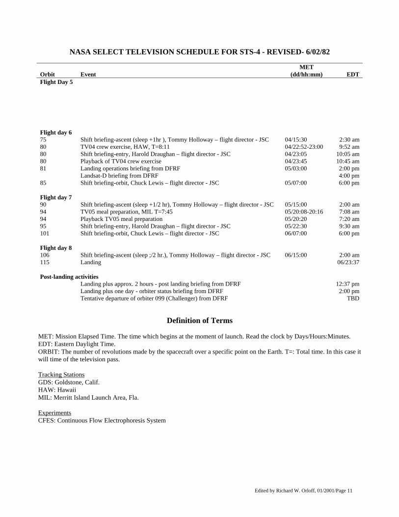
NASA SELECT TELEVISION SCHEDULE FOR STS-4 - REVISED- 6/02/82
Orbit
Event
MET (dd/hh:mm)
EDT
Flight Day 5
Flight day 6 75 Shift briefing-ascent (sleep +1hr ), Tommy Holloway – flight director - JSC 04/15:30 2:30 am 80 TV04 crew exercise, HAW, T=8:11 04/22:52-23:00 9:52 am 80 Shift briefing-entry, Harold Draughan – flight director - JSC 04/23:05 10:05 am 80 Playback of TV04 crew exercise 04/23:45 10:45 am 81 Landing operations briefing from DFRF 05/03:00 2:00 pm Landsat-D briefing from DFRF 4:00 pm 85 Shift briefing-orbit, Chuck Lewis – flight director - JSC 05/07:00 6:00 pm Flight day 7 90 Shift briefing-ascent (sleep +1/2 hr), Tommy Holloway – flight director - JSC 05/15:00 2:00 am 94 TV05 meal preparation, MIL T=7:45 05/20:08-20:16 7:08 am 94 Playback TV05 meal preparation 05/20:20 7:20 am 95 Shift briefing-entry, Harold Draughan – flight director - JSC 05/22:30 9:30 am 101 Shift briefing-orbit, Chuck Lewis – flight director - JSC 06/07:00 6:00 pm Flight day 8 106 Shift briefing-ascent (sleep ;/2 hr.), Tommy Holloway – flight director - JSC 06/15:00 2:00 am 115 Landing 06/23:37 Post-landing activities Landing plus approx. 2 hours - post landing briefing from DFRF 12:37 pm Landing plus one day - orbiter status briefing from DFRF 2:00 pm Tentative departure of orbiter 099 (Challenger) from DFRF TBD
Definition of Terms MET: Mission Elapsed Time. The time which begins at the moment of launch. Read the clock by Days/Hours:Minutes. EDT: Eastern Daylight Time. ORBIT: The number of revolutions made by the spacecraft over a specific point on the Earth. T=: Total time. In this case it will time of the television pass. Tracking Stations GDS: Goldstone, Calif. HAW: Hawaii MIL: Merritt Island Launch Area, Fla. Experiments CFES: Continuous Flow Electrophoresis System
Edited by Richard W. Orloff, 01/2001/Page 12
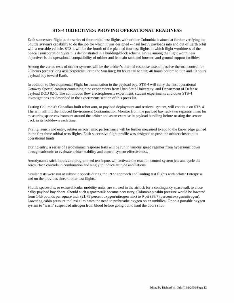
STS-4 OBJECTIVES: PROVING OPERATIONAL READINESS Each successive flight in the series of four orbital test flights with orbiter Columbia is aimed at further verifying the Shuttle system's capability to do the job for which it was designed -- haul heavy payloads into and out of Earth orbit with a reusable vehicle. STS-4 will be the fourth of the planned four test flights in which flight worthiness of the Space Transportation System is demonstrated in a building-block scheme. Prime among the flight worthiness objectives is the operational compatibility of orbiter and its main tank and booster, and ground support facilities. Among the varied tests of orbiter systems will be the orbiter’s thermal response tests of passive thermal control for 20 hours (orbiter long axis perpendicular to the Sun line); 80 hours tail to Sun; 40 hours bottom to Sun and 10 hours payload bay toward Earth. In addition to Developmental Flight Instrumentation in the payload bay, STS-4 will carry the first operational Getaway Special canister containing nine experiments from Utah State University; and Department of Defense payload DOD 82-1. The continuous flow electrophoresis experiment, student experiments and other STS-4 investigations are described in the experiments section of this press kit. Testing Columbia's Canadian-built robot arm, or payload deployment and retrieval system, will continue on STS-4. The arm will lift the Induced Environment Contamination Monitor from the payload bay rack two separate times for measuring space environment around the orbiter and as an exercise in payload handling before nesting the sensor back in its holddown each time. During launch and entry, orbiter aerodynamic performance will be further measured to add to the knowledge gained in the first three orbital tests flights. Each successive flight profile was designed to push the orbiter closer to its operational limits. During entry, a series of aerodynamic response tests will be run in various speed regimes from hypersonic down through subsonic to evaluate orbiter stability and control system effectiveness. Aerodynamic stick inputs and programmed test inputs will activate the reaction control system jets and cycle the aerosurface controls in combination and singly to induce attitude oscillations. Similar tests were run at subsonic speeds during the 1977 approach and landing test flights with orbiter Enterprise and on the previous three orbiter test flights. Shuttle spacesuits, or extravehicular mobility units, are stowed in the airlock for a contingency spacewalk to close balky payload bay doors. Should such a spacewalk become necessary, Columbia's cabin pressure would be lowered from 14.5 pounds per square inch (21/79 percent oxygen/nitrogen mix) to 9 psi (38/7) percent oxygen/nitrogen). Lowering cabin pressure to 9 psi eliminates the need to prebreathe oxygen on an umbilical Or on a portable oxygen system to "wash" suspended nitrogen from blood before going out to haul the doors shut.
Edited by Richard W. Orloff, 01/2001/Page 13
Edited by Richard W. Orloff, 01/2001/Page 14
LAUNCH PREPARATIONS, COUNTDOWN AND LIFTOFF Assembly of the STS-4 vehicle began March 29 with the placement of the two solid rocket booster aft assemblies on the deck of the Mobile Launcher Platform in the Vehicle Assembly Building's High Bay 3 at Kennedy Space Center. The left hand id rocket booster was topped off with its forward assembly on April 7. Stacking of the right hand booster was completed the following day. As on all three previous flights, the vehicle was stacked on the deck of the No. 1 Mobile Launcher Platform. Columbia arrived at Kennedy on April 6 aboard the modified 747 Shuttle Carrier Aircraft. Technicians worked overnight taking the orbiter off the top of the jumbo jet, and towed it into the Orbiter Processing Facility on April 7. Before the orbiter was modified for its next mission, engineers concentrated on fixing problems that were encountered during the most recent flight. During the five days of postflight troubleshooting done in the Orbiter Processing Facility, the faulty S-Band communications transponder was removed and shipped back to the vendor, and the orbiter's toilet was taken out and sent back to its manufacturer. Residual hypergolic propellants were drained out of the orbiter's orbital maneuvering and reaction control system modules and the payload carried on Columbia's third flight -- OSS-1 -was taken out of the cargo bay April 13 and returned to the Operations and Checkout Building for removal of the experiments. While work was progressing on the orbiter, stacking and preflight checkout of the other Shuttle elements was underway and on schedule. On April 16, the external tank was moved out of its checkout cell and mated to the twin booster rockets already assembled on the Mobile Launcher Platform. The tank, which had arrived Jan. 22 by ocean-going barge, underwent its preflight checkout and systems testing in High Bay 4. Several components on the Columbia were changed out in preparation for its fourth flight. A new No. 3 inertial measurement unit was installed, and all the tires on both the main and nose landing gears were replaced. One significant modification to Columbia for STS-4 and subsequent flights was the installation of a payload bay liner to reduce contamination to cargo bay experiments. High pressure fuel pumps on all three main engines were removed and inspected. As a result, the fuel pump on the No. 2 engine was sent to the vendor for replacement of some components, and the pump was successfully tested at the NASA National Space Technology Laboratories, Bay St. Louis, Miss., during a 300 second single engine firing. The fuel pump on the No. 1 engine was also replaced due to a cracked turbine blade. The modification period for STS-4 did not call for a scheduled "power down" period. However, it was necessary to power down Columbia for a week, starting April 24. while a heat interchanger was removed and replaced. Also undertaken during the power down period was the removal and replacement of 12 attitude control jets. A postflight inspection of the thrusters found varying amounts of gypsum sand in the powerful small rocket engines, a result of Columbia's landing at the Northrup Strip in White Sands, N.M. The forward reaction control system was taken out of the spaceship April 24 and moved to the Hypergolic Maintenance Facility where six thrusters were pulled and replaced with new ones. Six other thrusters were pulled out of the twin aft maneuvering pods (three right and three left thrusters) and also replaced with new ones. The Induced Environmental Contamination Monitor was removed and shipped back to NASA's Marshall Space Flight Center, Huntsville, Ala., for analysis. It was returned to Kennedy and installed back in the cargo bay on May 5
Edited by Richard W. Orloff, 01/2001/Page 15
Two other STS-4 experiments were also installed while Columbia was in the processing hangar. The first "Getaway Special" to fly aboard Columbia was installed May 11. That same day, installation started on the Continuous Flow Electrophoresis System experiment. Astronauts Mattingly and Hartsfield participated in a Crew Equipment Interface Test on May 9 to familiarize themselves with the location and use of experiments and equipment carried onboard the STS-4 mission. Just days before Columbia's scheduled move to the Vehicle Assembly Building, a faulty actuator was discovered during functional checks of the Shuttle main engines. The orbiter actuator was replaced and successfully retested. Another last-minute task was the replacement of a check valve in a gaseous oxygen line in the orbiter's main propulsion system feed system. The payload bay doors were closed for Columbia's move to the Vehicle Assembly Building on May 17 and leak and functional checks of the three Shuttle main engines and checks of the hydraulically-controlled flight control system were completed. Finally, the orbiter was closed out for the move and weighed before moving out of the Orbiter Processing Facility on May 19. Workers recorded their shortest turnaround time to date in the Orbiter Processing Facility, preparing the reusable spaceship for the STS-4 mission in 40 working days. Columbia spent 53 working days in the facility for the STS-3 mission and 99 days for Columbia's second flight. On May 20, the Columbia was mechanically mated to the external tank and solid rocket boosters, completing assembly of the STS-4 vehicle. A Shuttle Interface Test was conducted from May 21-25 to verify the mechanical, fluid and electrical connections between the orbiter, external tank and booster rockets and to verify the function of onboard systems. Unlike previous flows, the mission simulations normally done at the end of the Shuttle Interface Test were not performed, reducing the amount of testing in the VAB. The STS-4 vehicle was moved to Pad A of Complex 39 on May 26 to undergo final checkout and propellant servicing for launch. Pad to vehicle connections were verified, followed by a Dry Countdown Demonstration Test with the STS-4 prime crew members on May 29. The test simulates as closely as possible the final hours of an actual Shuttle launch countdown, except that the external tank is not filled with cryogenic propellants. A wet cryogenic tanking test was conducted on June 2 to verify the automatic propellant loading system and ability of Shuttle systems to perform under cryogenic conditions. The test also verifies the integrity of the external tank outer insulation. The flight crew did not participate in this test. The preflight servicing of Columbia with hypergolic propellants was scheduled from June 8-12. During this time, the monomethyl hydrazine and nitrogen tetroxide propellants are loaded into the orbiter's forward and aft maneuvering and reaction control system tanks. Countdown preparations were to begin June 14, leading to a pick up of the 87-hour Shuttle Launch Countdown on June 23. The launch countdown for STS-4 will be conducted from Firing Room 1 of the Launch Control Center by a government/industry team of about 200 persons. The STS-4 launch countdown will follow a similar schedule to earlier countdowns. The STS-4 countdown is longer, because of a requirement to open the payload bay doors during the count, and the duration and distribution of hold times have changed.

Edited by Richard W. Orloff, 01/2001/Page 16
Precount activities should include activation of the fuel cell system, pressurization of the orbital maneuvering and reaction control systems, a review of flight software stored in the bulk memory units, loading of power reactant storage and distribution cryogenic oxygen and hydrogen tanks, installation of the mid-deck experiments and retraction of the rotating service structure. The terminal portion of the countdown starts at T-6 hours with loading of cryogenic propellants into the external tank. A one-hour hold at T-3 hours will allow time for an inspection of the external tank insulation, and boarding of Columbia by the crew should occur at T-1 hour and 50 minutes. At T-9 minutes, the automatic ground launch sequencer takes over command of the countdown, issuing critical commands down to main engine start at T-6.8 seconds and maintaining a cutoff capability to liftoff.
Edited by Richard W. Orloff, 01/2001/Page 17
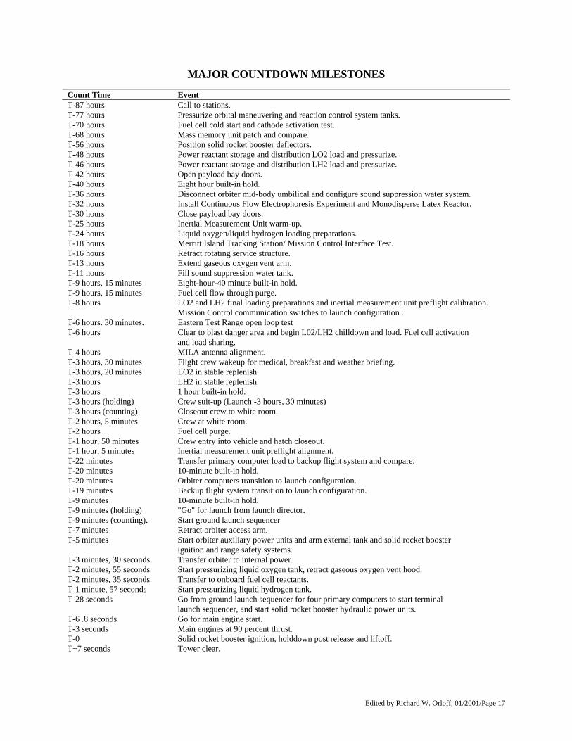
MAJOR COUNTDOWN MILESTONES Count Time Event T-87 hours Call to stations. T-77 hours Pressurize orbital maneuvering and reaction control system tanks. T-70 hours Fuel cell cold start and cathode activation test. T-68 hours Mass memory unit patch and compare. T-56 hours Position solid rocket booster deflectors. T-48 hours Power reactant storage and distribution LO2 load and pressurize. T-46 hours Power reactant storage and distribution LH2 load and pressurize. T-42 hours Open payload bay doors. T-40 hours Eight hour built-in hold. T-36 hours Disconnect orbiter mid-body umbilical and configure sound suppression water system. T-32 hours Install Continuous Flow Electrophoresis Experiment and Monodisperse Latex Reactor. T-30 hours Close payload bay doors. T-25 hours Inertial Measurement Unit warm-up. T-24 hours Liquid oxygen/liquid hydrogen loading preparations. T-18 hours Merritt Island Tracking Station/ Mission Control Interface Test. T-16 hours Retract rotating service structure. T-13 hours Extend gaseous oxygen vent arm. T-11 hours Fill sound suppression water tank. T-9 hours, 15 minutes Eight-hour-40 minute built-in hold. T-9 hours, 15 minutes Fuel cell flow through purge. T-8 hours LO2 and LH2 final loading preparations and inertial measurement unit preflight calibration.
Mission Control communication switches to launch configuration . T-6 hours. 30 minutes. Eastern Test Range open loop test T-6 hours Clear to blast danger area and begin L02/LH2 chilldown and load. Fuel cell activation
and load sharing. T-4 hours MILA antenna alignment. T-3 hours, 30 minutes Flight crew wakeup for medical, breakfast and weather briefing. T-3 hours, 20 minutes LO2 in stable replenish. T-3 hours LH2 in stable replenish. T-3 hours 1 hour built-in hold. T-3 hours (holding) Crew suit-up (Launch -3 hours, 30 minutes) T-3 hours (counting) Closeout crew to white room. T-2 hours, 5 minutes Crew at white room. T-2 hours Fuel cell purge. T-1 hour, 50 minutes Crew entry into vehicle and hatch closeout. T-1 hour, 5 minutes Inertial measurement unit preflight alignment. T-22 minutes Transfer primary computer load to backup flight system and compare. T-20 minutes 10-minute built-in hold. T-20 minutes Orbiter computers transition to launch configuration. T-19 minutes Backup flight system transition to launch configuration. T-9 minutes 10-minute built-in hold. T-9 minutes (holding) "Go" for launch from launch director. T-9 minutes (counting). Start ground launch sequencer T-7 minutes Retract orbiter access arm. T-5 minutes Start orbiter auxiliary power units and arm external tank and solid rocket booster
ignition and range safety systems. T-3 minutes, 30 seconds Transfer orbiter to internal power. T-2 minutes, 55 seconds Start pressurizing liquid oxygen tank, retract gaseous oxygen vent hood. T-2 minutes, 35 seconds Transfer to onboard fuel cell reactants. T-1 minute, 57 seconds Start pressurizing liquid hydrogen tank. T-28 seconds Go from ground launch sequencer for four primary computers to start terminal
launch sequencer, and start solid rocket booster hydraulic power units. T-6 .8 seconds Go for main engine start. T-3 seconds Main engines at 90 percent thrust. T-0 Solid rocket booster ignition, holddown post release and liftoff. T+7 seconds Tower clear.
Edited by Richard W. Orloff, 01/2001/Page 18
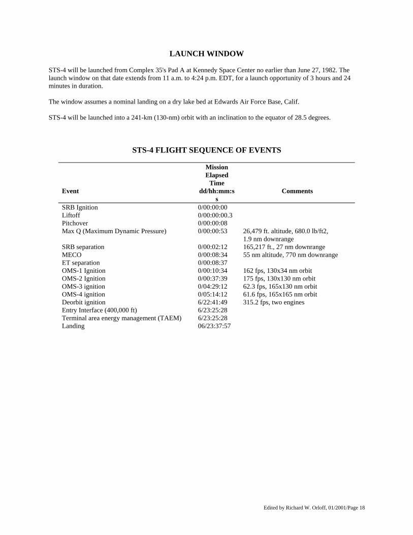
LAUNCH WINDOW STS-4 will be launched from Complex 35's Pad A at Kennedy Space Center no earlier than June 27, 1982. The launch window on that date extends from 11 a.m. to 4:24 p.m. EDT, for a launch opportunity of 3 hours and 24 minutes in duration. The window assumes a nominal landing on a dry lake bed at Edwards Air Force Base, Calif. STS-4 will be launched into a 241-km (130-nm) orbit with an inclination to the equator of 28.5 degrees.
STS-4 FLIGHT SEQUENCE OF EVENTS
Event
Mission Elapsed
Time dd/hh:mm:s
s
Comments
SRB Ignition 0/00:00:00 Liftoff 0/00:00:00.3 Pitchover 0/00:00:08 Max Q (Maximum Dynamic Pressure) 0/00:00:53 26,479 ft. altitude, 680.0 lb/ft2,
1.9 nm downrange SRB separation 0/00:02:12 165,217 ft., 27 nm downrange MECO 0/00:08:34 55 nm altitude, 770 nm downrange ET separation 0/00:08:37 OMS-1 Ignition 0/00:10:34 162 fps, 130x34 nm orbit OMS-2 Ignition 0/00:37:39 175 fps, 130x130 nm orbit OMS-3 ignition 0/04:29:12 62.3 fps, 165x130 nm orbit OMS-4 ignition 0/05:14:12 61.6 fps, 165x165 nm orbit Deorbit ignition 6/22:41:49 315.2 fps, two engines Entry Interface (400,000 ft) 6/23:25:28 Terminal area energy management (TAEM) 6/23:25:28 Landing 06/23:37:57
Edited by Richard W. Orloff, 01/2001/Page 19
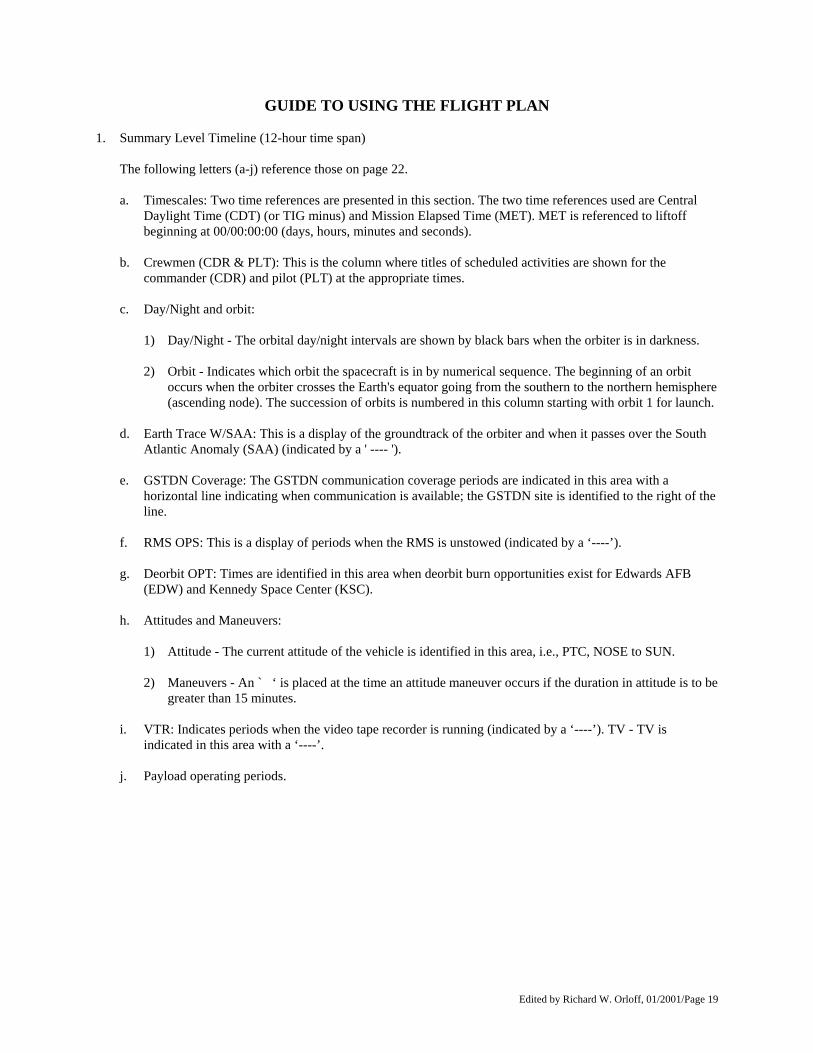
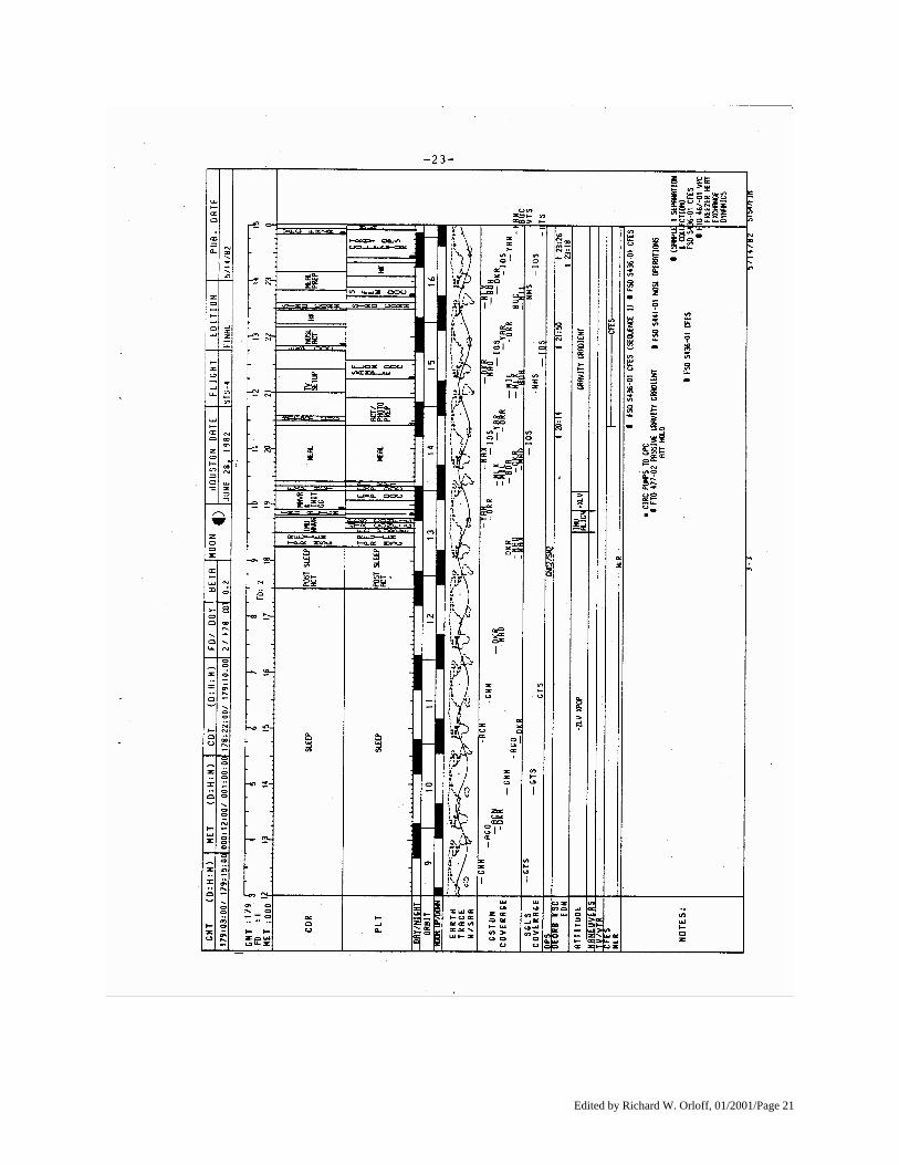
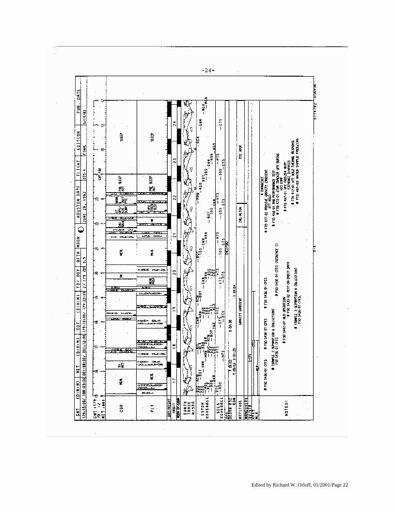
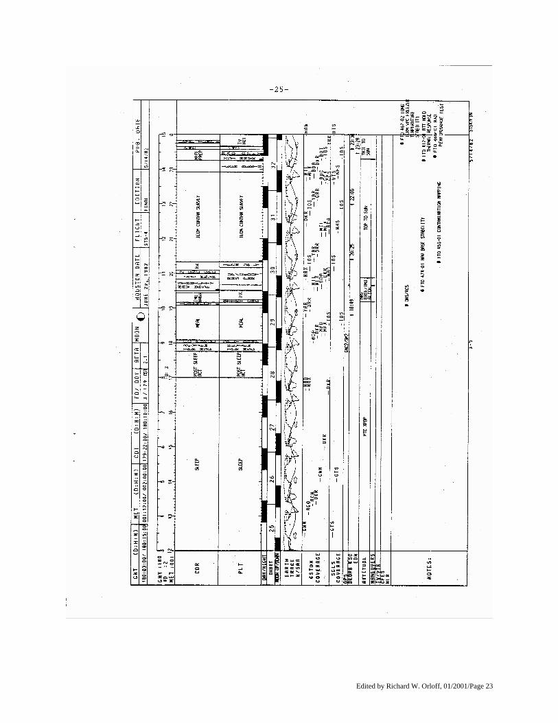
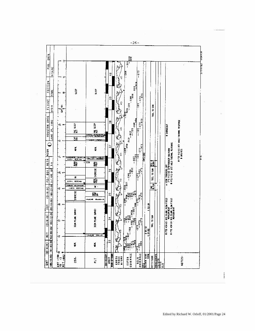
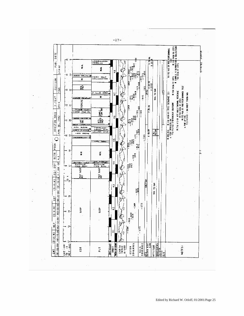
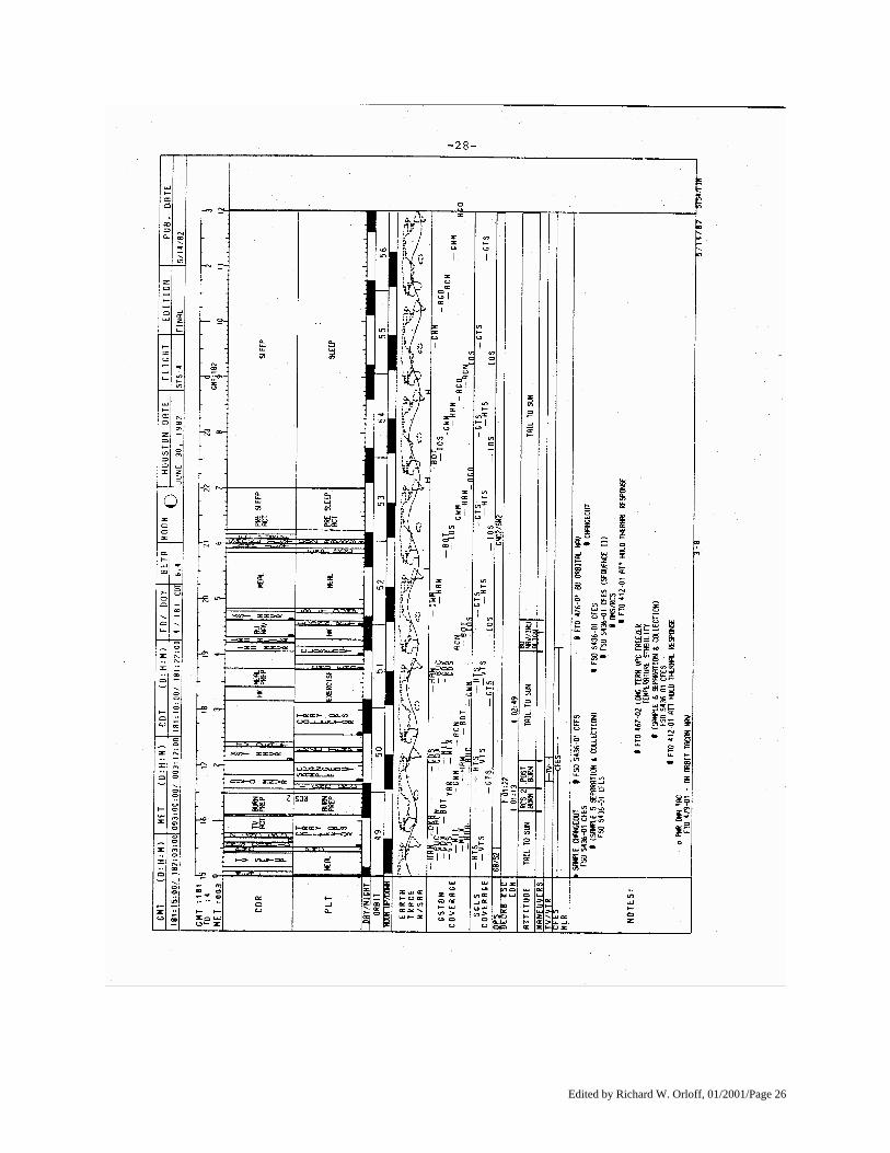
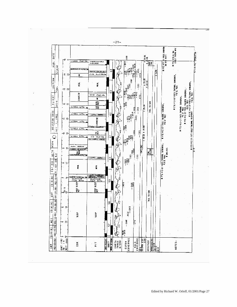
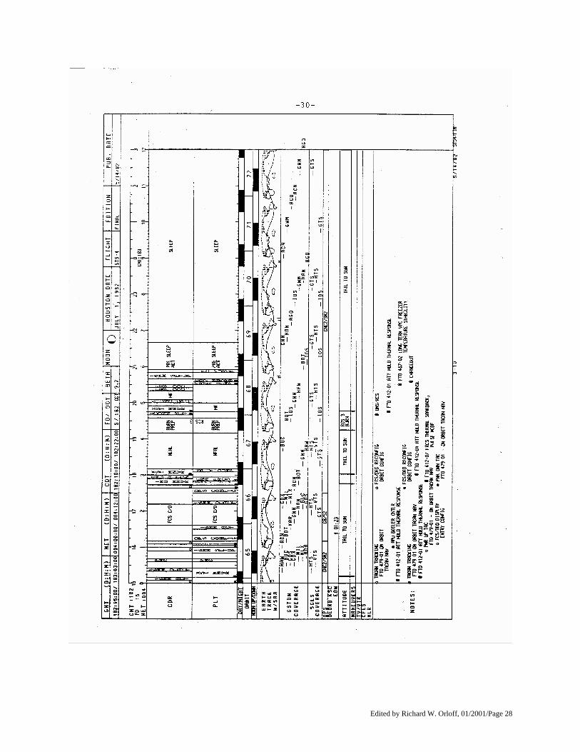
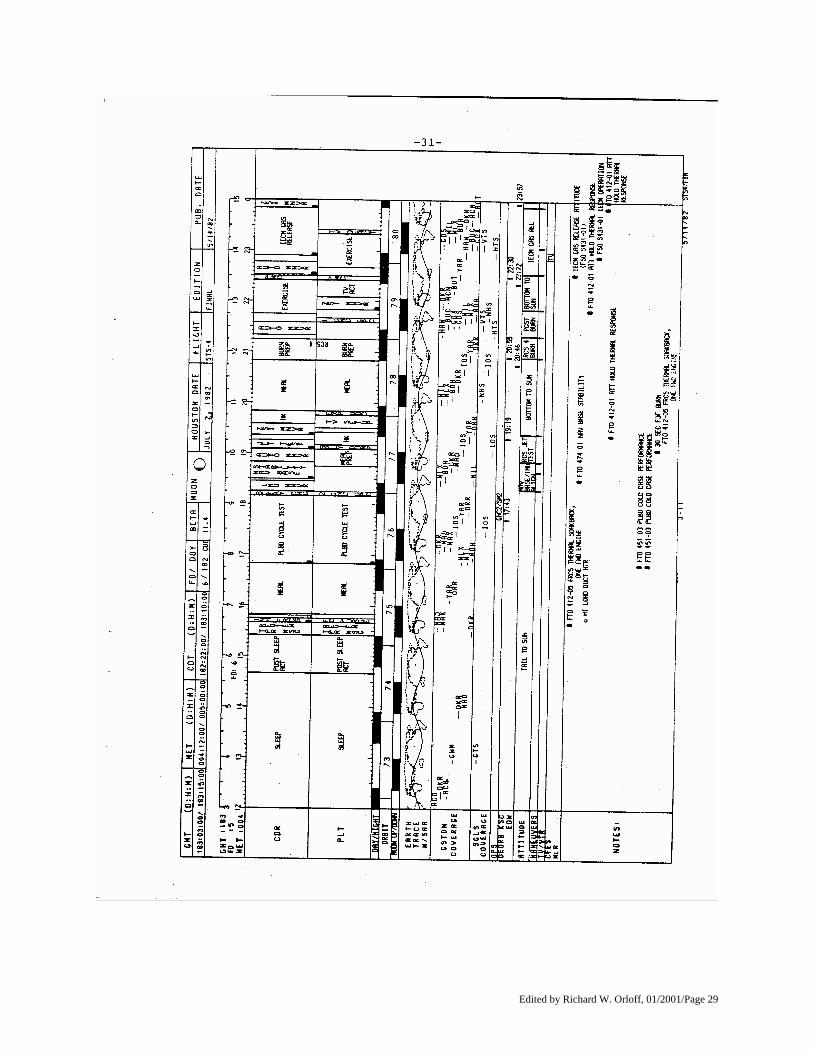
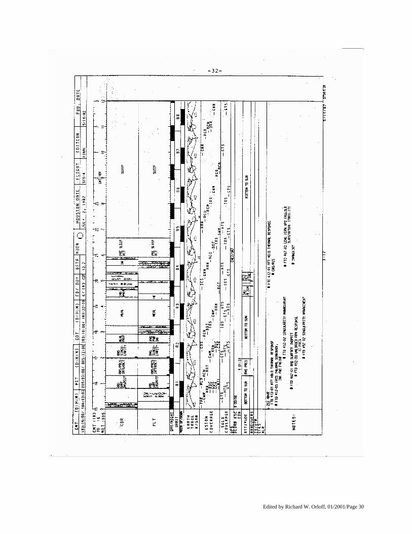
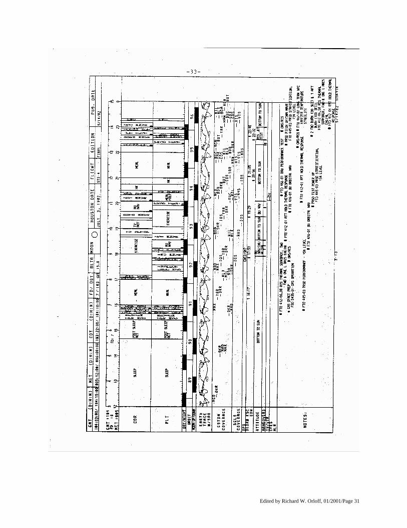
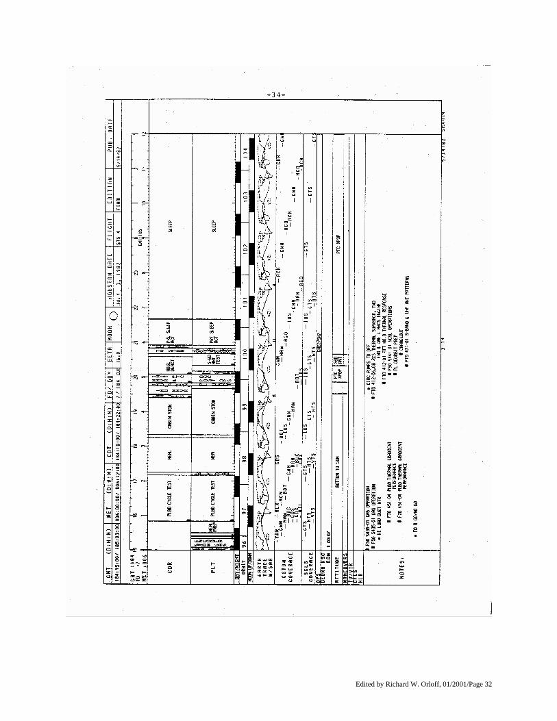
GUIDE TO USING THE FLIGHT PLAN 1. Summary Level Timeline (12-hour time span)
The following letters (a-j) reference those on page 22.
a. Timescales: Two time references are presented in this section. The two time references used are Central Daylight Time (CDT) (or TIG minus) and Mission Elapsed Time (MET). MET is referenced to liftoff beginning at 00/00:00:00 (days, hours, minutes and seconds).
b. Crewmen (CDR & PLT): This is the column where titles of scheduled activities are shown for the
commander (CDR) and pilot (PLT) at the appropriate times. c. Day/Night and orbit:
1) Day/Night - The orbital day/night intervals are shown by black bars when the orbiter is in darkness. 2) Orbit - Indicates which orbit the spacecraft is in by numerical sequence. The beginning of an orbit
occurs when the orbiter crosses the Earth's equator going from the southern to the northern hemisphere (ascending node). The succession of orbits is numbered in this column starting with orbit 1 for launch.
d. Earth Trace W/SAA: This is a display of the groundtrack of the orbiter and when it passes over the South
Atlantic Anomaly (SAA) (indicated by a ' ---- '). e. GSTDN Coverage: The GSTDN communication coverage periods are indicated in this area with a
horizontal line indicating when communication is available; the GSTDN site is identified to the right of the line.
f. RMS OPS: This is a display of periods when the RMS is unstowed (indicated by a ‘----’). g. Deorbit OPT: Times are identified in this area when deorbit burn opportunities exist for Edwards AFB
(EDW) and Kennedy Space Center (KSC). h. Attitudes and Maneuvers:
1) Attitude - The current attitude of the vehicle is identified in this area, i.e., PTC, NOSE to SUN. 2) Maneuvers - An ` ‘ is placed at the time an attitude maneuver occurs if the duration in attitude is to be
greater than 15 minutes.
i. VTR: Indicates periods when the video tape recorder is running (indicated by a ‘----’). TV - TV is indicated in this area with a ‘----’.
j. Payload operating periods.
Edited by Richard W. Orloff, 01/2001/Page 20
Edited by Richard W. Orloff, 01/2001/Page 21
Edited by Richard W. Orloff, 01/2001/Page 22
Edited by Richard W. Orloff, 01/2001/Page 23
Edited by Richard W. Orloff, 01/2001/Page 24
Edited by Richard W. Orloff, 01/2001/Page 25
Edited by Richard W. Orloff, 01/2001/Page 26
Edited by Richard W. Orloff, 01/2001/Page 27
Edited by Richard W. Orloff, 01/2001/Page 28
Edited by Richard W. Orloff, 01/2001/Page 29
Edited by Richard W. Orloff, 01/2001/Page 30
Edited by Richard W. Orloff, 01/2001/Page 31
Edited by Richard W. Orloff, 01/2001/Page 32
Edited by Richard W. Orloff, 01/2001/Page 33
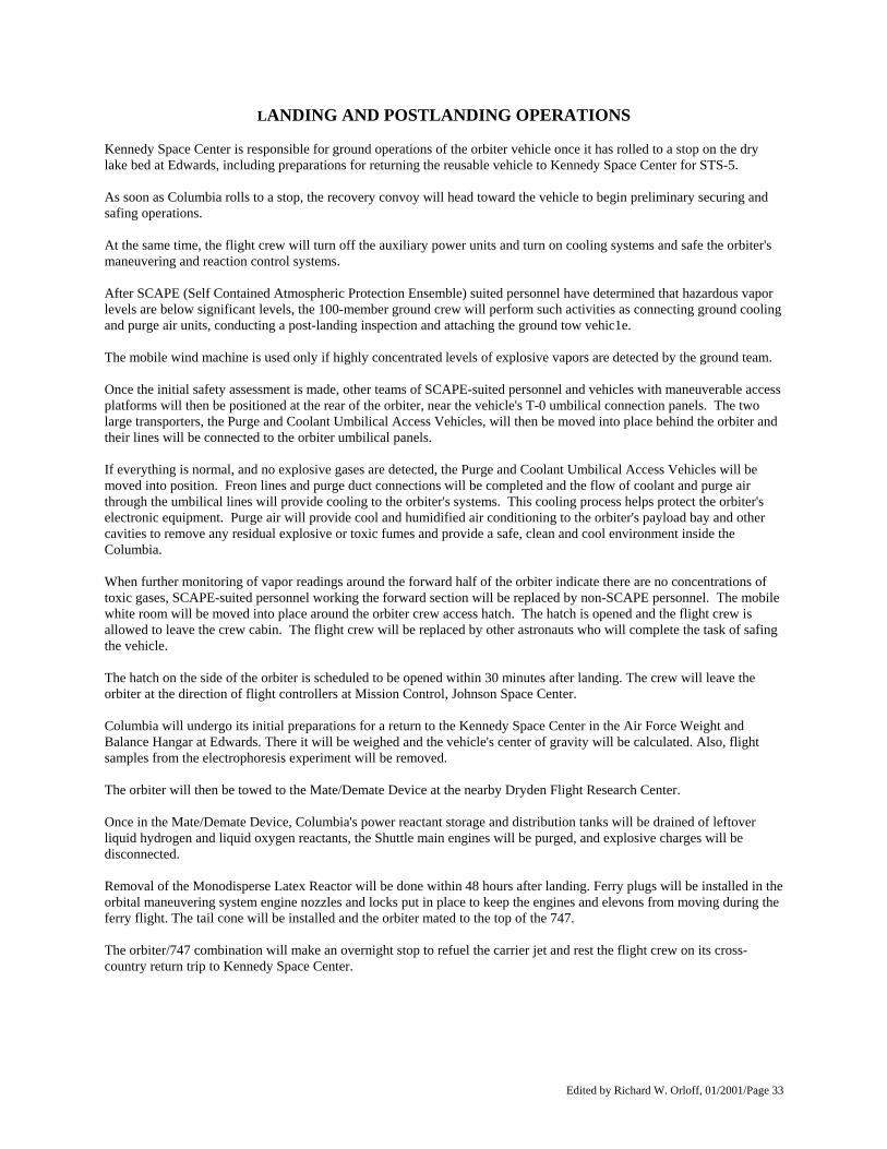
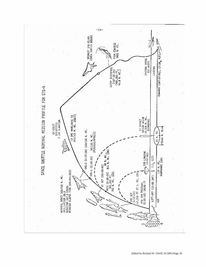
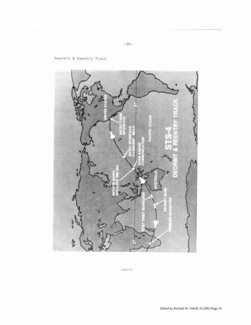
LANDING AND POSTLANDING OPERATIONS Kennedy Space Center is responsible for ground operations of the orbiter vehicle once it has rolled to a stop on the dry lake bed at Edwards, including preparations for returning the reusable vehicle to Kennedy Space Center for STS-5. As soon as Columbia rolls to a stop, the recovery convoy will head toward the vehicle to begin preliminary securing and safing operations. At the same time, the flight crew will turn off the auxiliary power units and turn on cooling systems and safe the orbiter's maneuvering and reaction control systems. After SCAPE (Self Contained Atmospheric Protection Ensemble) suited personnel have determined that hazardous vapor levels are below significant levels, the 100-member ground crew will perform such activities as connecting ground cooling and purge air units, conducting a post-landing inspection and attaching the ground tow vehic1e. The mobile wind machine is used only if highly concentrated levels of explosive vapors are detected by the ground team. Once the initial safety assessment is made, other teams of SCAPE-suited personnel and vehicles with maneuverable access platforms will then be positioned at the rear of the orbiter, near the vehicle's T-0 umbilical connection panels. The two large transporters, the Purge and Coolant Umbilical Access Vehicles, will then be moved into place behind the orbiter and their lines will be connected to the orbiter umbilical panels. If everything is normal, and no explosive gases are detected, the Purge and Coolant Umbilical Access Vehicles will be moved into position. Freon lines and purge duct connections will be completed and the flow of coolant and purge air through the umbilical lines will provide cooling to the orbiter's systems. This cooling process helps protect the orbiter's electronic equipment. Purge air will provide cool and humidified air conditioning to the orbiter's payload bay and other cavities to remove any residual explosive or toxic fumes and provide a safe, clean and cool environment inside the Columbia. When further monitoring of vapor readings around the forward half of the orbiter indicate there are no concentrations of toxic gases, SCAPE-suited personnel working the forward section will be replaced by non-SCAPE personnel. The mobile white room will be moved into place around the orbiter crew access hatch. The hatch is opened and the flight crew is allowed to leave the crew cabin. The flight crew will be replaced by other astronauts who will complete the task of safing the vehicle. The hatch on the side of the orbiter is scheduled to be opened within 30 minutes after landing. The crew will leave the orbiter at the direction of flight controllers at Mission Control, Johnson Space Center. Columbia will undergo its initial preparations for a return to the Kennedy Space Center in the Air Force Weight and Balance Hangar at Edwards. There it will be weighed and the vehicle's center of gravity will be calculated. Also, flight samples from the electrophoresis experiment will be removed. The orbiter will then be towed to the Mate/Demate Device at the nearby Dryden Flight Research Center. Once in the Mate/Demate Device, Columbia's power reactant storage and distribution tanks will be drained of leftover liquid hydrogen and liquid oxygen reactants, the Shuttle main engines will be purged, and explosive charges will be disconnected. Removal of the Monodisperse Latex Reactor will be done within 48 hours after landing. Ferry plugs will be installed in the orbital maneuvering system engine nozzles and locks put in place to keep the engines and elevons from moving during the ferry flight. The tail cone will be installed and the orbiter mated to the top of the 747. The orbiter/747 combination will make an overnight stop to refuel the carrier jet and rest the flight crew on its cross-country return trip to Kennedy Space Center.
Edited by Richard W. Orloff, 01/2001/Page 34
Edited by Richard W. Orloff, 01/2001/Page 35
Edited by Richard W. Orloff, 01/2001/Page 36
Edited by Richard W. Orloff, 01/2001/Page 37
Edited by Richard W. Orloff, 01/2001/Page 38
Edited by Richard W. Orloff, 01/2001/Page 39
Edited by Richard W. Orloff, 01/2001/Page 40
IF THINGS GO WRONG
(Contingencies) While there has never been a launch abort in any U.S. manned space flight program, flight crews and flight controllers must still train and plan for emergency early landing. The safe return of the flight crew, the orbiter and its payloads to an intact landing is emphasized in abort planning philosophy. The preferred type of Shuttle launch abort is the abort-to-orbit in which combined thrust from main engines and orbital maneuvering system engines is enough to reach a minimal 194-km (105-mm) orbit. An abort-to-orbit would be called for if one main engine should shut down before enough velocity is reached to yield a 235-km (127-nm) orbit. Earlier shutdown of one main engine would force an abort-once-around situation in which Columbia would land near the end of one orbit at Dryden Flight Research Facility. Also, any critical systems failure aboard Columbia immediately after orbital insertion calls for an abort-once-around landing. Loss of a second main engine during launch forces a trans-Atlantic abort landing or "Press to Rota," depending on when the problem occurs Shutdown of one or more main engines early in the launch phase call for a return-to-launch-site abort. Once an abort decision is made, Columbia and the external tank would be flown in a pitch-around maneuver to heads-up and pointed back along the ground track to Kennedy Space Center. Whatever main engine thrust still available would then be used to kill off eastward velocity, and reverse direction until the Kennedy Space Center runway could be reached by gliding along a modified entry trajectory. Major orbiter systems failures during ascent could also force a return-to-launch-site abort Loss of control or impending catastrophic failure during ascent, from tower clear to 30,480 m (100,000 ft.) calls for crew ejection. Loss of two main engines prior to seven minutes of flight also calls for crew ejection after descending below 30,480 m (100,000 ft). Contingency landing sites, in addition to Edwards and Northrup, are Hickam Air Force Base/Honolulu International Airport, Hawaii; Kadena Air Base, Okinawa; and Rota Naval Station, Spain. The Kennedy Space Center's 4,570-m (15,000-ft.) Shuttle Landing Facility is the designated secondary landing site.
Edited by Richard W. Orloff, 01/2001/Page 41
CONFIGURATION
STS-4: COLUMBIA'S FINAL SHAKEDOWN FLIGHT Aside from a quilted, plastic-film payload bay liner added since STS-3, Columbia's configuration remains unchanged from the third flight. The payload bay liner installation for STS-4 was planned prior to the start of the orbital flight test program. Food stowed in middeck food lockers again will be heated by a carry-on food warmer. Experiments stowed and operated on the middeck include the Monodisperse Latex Reactor, repeated from STS-3; and the Continuous Flow Electrophoresis System. Payloads and experiments in the payload bay are the Development Flight Instrumentation with Induced Environment Contamination Monitor attached; one Getaway Special canister; the Aerodynamic Coefficient Identification Package; and Department of Defense payload DOD 82-1. The STS-4 liftoff weight will be 2,033,404 kg (4,482,888 lb.).
Edited by Richard W. Orloff, 01/2001/Page 42
STS-4 EXPERIMENTS
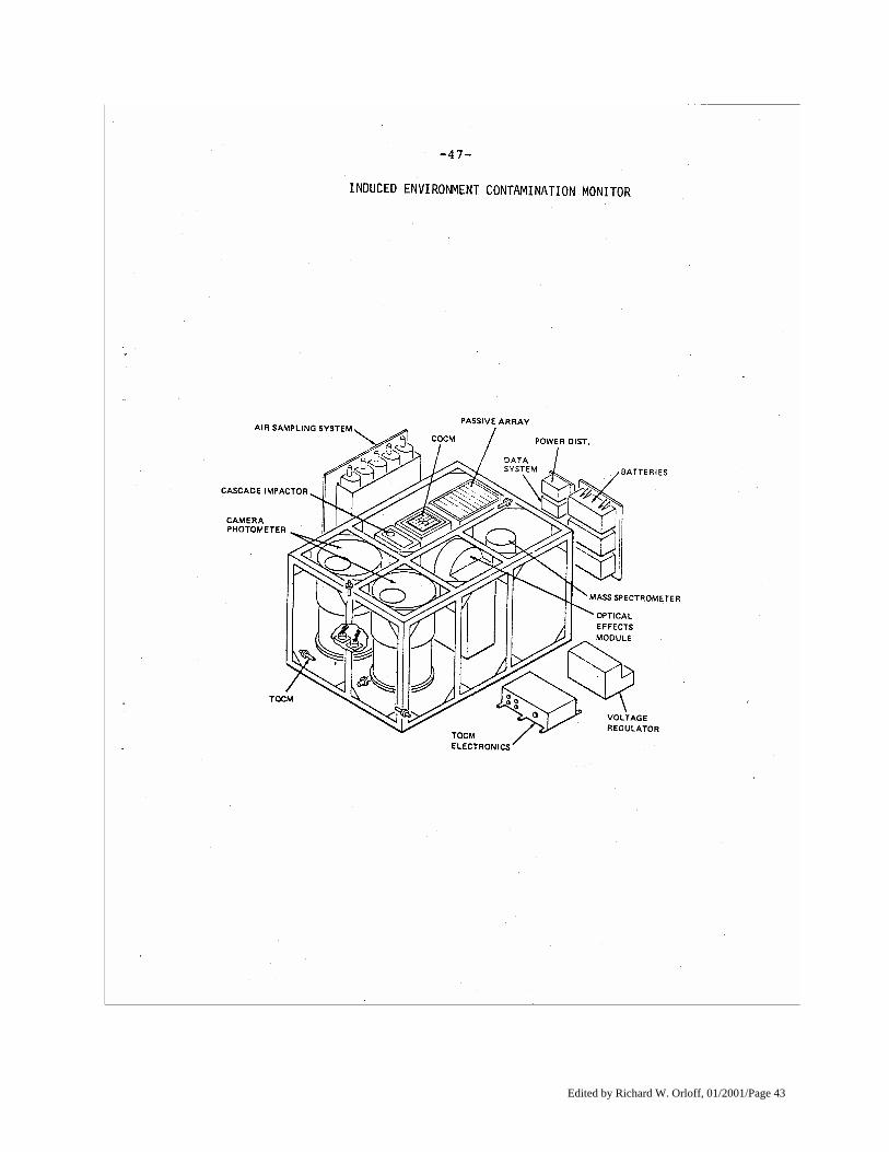
Induced Environment Contamination Monitor The Induced Environment Contamination Monitor (IECM) is a desk-sized detector containing 11 instruments to check for contaminants in and around the Space Shuttle orbiter cargo bay which might adversely affect delicate experiments carried aboard. The monitor, developed by Marshall Space Flight Center is scheduled to make its third flight into space on STS-4. In addition to its regular in-place monitoring activities in the orbiter cargo bay during this seven-day flight, the crew will activate the remote manipulator system to pick up this 363-kg (800-lb.) package and place it at various locations around the orbiter. During this "mapping" exercise, the monitor will employ an instrument added for this mission, the plume pressure gauge. This instrument will measure the pressure wave of the plume emitted by the firing of reaction control jets at the nose of the orbiter. The monitor will be attached to a release mechanism (also developed by Marshall) enabling it to be released and lifted up by the remote manipulator system. Contaminants to be monitored during Shuttle flights include any outgassing from materials within the Shuttle, as well as gases from the reaction jets which control the vehicle in orbit. The monitor operates during pre-launch, ascent, on-orbit, descent, landing, and 45 minutes after landing. The on-orbit measurements include molecular return flux, background spectral intensity, molecular deposition and optical surface effects. During the other mission phases, dew point, humidity, aerosol content, and trace gases will be measured, as well as optical surface effects and molecular deposition. These measurements are made with 11 separate instruments: a humidity monitor, dew point hygrometer, air sampler, cascade impactor, passive sample array, optical effects module, temperature-controlled quartz crystal microbalance, cryogenic quartz crystal microbalance, camera/photometer, mass spectrometer and a plume pressure gauge. On the orbiter's return flight from its landing site to Kennedy Space Center aboard a 747 transport airplane, another passive sample array is added to further check for contaminants. NASA began strong manned mission contamination control efforts during the Skylab missions of 1973-74 and, recognizing the possible limiting effects induced contamination might have on sophisticated observational programs planned for the 1980s, committed to an effort to insure that the induced environment would not be a problem on the Shuttle. The purpose of the monitor is to measure the actual environment to determine whether the strict controls placed on the Shuttle system have solved the contamination problem. After each Shuttle flight, the unit is to be returned to the Marshall Center for refurbishment. The flight data is then to be combined with orbiter data furnished by the Johnson Space Center for a comprehensive analysis.
Edited by Richard W. Orloff, 01/2001/Page 43
Edited by Richard W. Orloff, 01/2001/Page 44
With the monitor instrumentation, contaminant sources are identified for possible elimination. The experiment provides data on the interaction of the induced and natural environments, and provides critical data for planning of
future Shuttle payloads. The unit will also be used to monitor the induced atmosphere during Spacelab missions one and two. A brief description of the objectives of each of the monitor's instruments follows: Mass Spectrometer -- The mass spectrometer will measure molecular return flux, from which molecular column density may be calculated. The purpose of the mass spectrometer measurement is twofold: to define the offgassing and outgassing molecules transported to surfaces in the Shuttle bay for correlation to actual deposition measurements on optical and temperature-controlled surfaces, and to define the gas cloud (induced atmosphere) through which optical experiments must look. Camera/Photometer -- Of particular concern to the astronomical community is the effect on astronomical experiments of induced contamination in the form of individual particles and general background. Even a moderate particulate generation rate by the Shuttle would severely limit the performance of an infrared telescope. Two automated Camera/Photometers will make optical measurements of both the induced particulate environment and the background brightness. Cryogenic Quartz Crystal Microbalance -- The objective of the cryogenic quartz crystal microbalance is to provide a record of the adsorption and desorption of molecular contamination in the Shuttle cargo bay. On specific Shuttle missions when the cargo bay is oriented so that it does not receive direct solar heating for long periods of time, the instrument will have the special objective of measuring molecular water vapor. Temperature-Controlled Quartz Crystal Microbalance -- The temperature-controlled quartz crystal microbalance is designed to detect the adsorption or desorption of molecular contamination in the Shuttle cargo bay as a function of temperature. The contamination sources will be characterized as a function of direction and events. Contamination will also be grouped into categories according to desorption activation energies. Optical Effects Module -- The Optical Effects Module is designed to provide the Shuttle cargo bay user community with information applicable to assessing the contamination hazards likely to be encountered by optical components of space-borne instrumentation. The optical degradation of some typical window materials will be measured and monitored during prelaunch, orbital, and postlanding phases. Optical property changes due to deposition of particulates and molecular films will be discriminately measured utilizing an integrated scattered light measurement in conjunction with direct, self-calibrating transmission measurements. Passive Sample Array -- An array of optical samples will be exposed to the natural and induced environments of the Shuttle cargo bay for later return and analysis on the around to evaluate the optical effects of contamination. Inclusion of the Passive Sample Array permits the greater scope and range of analysis required to assess more fully the physical mechanisms of degradation due to deposited contaminants. The samples are measured in the laboratory prior to experiment integration. Control samples are included in these measurements and are then stored in a controlled, "clean" environment. Following retrieval of samples, whether during preflight activities or after the flight, the measurements are repeated and the analysis is based on any encountered changes. Cascade Impactor -- The cascade impactor provides a determination of concentration and particle size distribution, as a function of time, of air-suspended contaminants in the spacecraft environment during ground-based, ascent, descent and post-landing phases. In addition to the cascade stages, the impactor measures the
Edited by Richard W. Orloff, 01/2001/Page 45
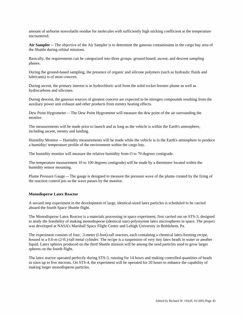
amount of airborne nonvolatile residue for molecules with sufficiently high sticking coefficient at the temperature encountered. Air Sampler -- The objective of the Air Sampler is to determine the gaseous contaminants in the cargo bay area of the Shuttle during orbital missions. Basically, the requirements can be categorized into three groups: ground-based; ascent; and descent sampling phases. During the ground-based sampling, the presence of organic and silicone polymers (such as hydraulic fluids and lubricants) is of most concern. During ascent, the primary interest is in hydrochloric acid from the solid rocket booster plume as well as hydrocarbons and silicones. During descent, the gaseous sources of greatest concern are expected to be nitrogen compounds resulting from the auxiliary power unit exhaust and other products from reentry heating effects. Dew Point Hygrometer -- The Dew Point Hygrometer will measure the dew point of the air surrounding the monitor. The measurements will be made prior to launch and as long as the vehicle is within the Earth's atmosphere, including ascent, reentry and landing. Humidity Monitor -- Humidity measurements will be made while the vehicle is in the Earth's atmosphere to produce a humidity/ temperature profile of the environment within the cargo bay. The humidity monitor will measure the relative humidity from O to 70 degrees centigrade. The temperature measurement 10 to 100 degrees centigrade) will be made by a thermistor located within the humidity sensor mounting. Plume Pressure Gauge -- The gauge is designed to measure the pressure wave of the plume created by the firing of the reaction control jets as the wave passes by the monitor. Monodisperse Latex Reactor A second step experiment in the development of large, identical-sized latex particles is scheduled to be carried aboard the fourth Space Shuttle flight. The Monodisperse Latex Reactor is a materials processing in space experiment, first carried out on STS-3, designed to study the feasibility of making monodisperse (identical size) polystyrene latex microspheres in space. The project was developed at NASA's Marshall Space Flight Center and Lehigh University in Bethlehem, Pa. The experiment consists of four, .3-meter (l-foot)-tall reactors, each containing a chemical latex-forming recipe, housed in a 0.6-m (2-ft.)-tall metal cylinder. The recipe is a suspension of very tiny latex beads in water or another liquid. Latex spheres produced on the third Shuttle mission will be among the seed particles used to grow larger spheres on the fourth flight. The latex reactor operated perfectly during STS-3, running for 14 hours and making controlled quantities of beads in sizes up to five microns. On STS-4, the experiment will be operated for 20 hours to enhance the capability of making larger monodisperse particles.
Edited by Richard W. Orloff, 01/2001/Page 46
Edited by Richard W. Orloff, 01/2001/Page 47
On Earth, these beads can be produced only up to about three microns and still be monodisperse. The experiment which will be flown on a total of four flights will help determine if much larger (larger than 20 microns) monodisperse beads can be produced practically and economically in space. These latex particles may have major medical and industrial research applications. Some of the proposed applications of the latex beads include measuring the size of pores in the wall of the intestine in cancer research; measuring the size of pores in the human eye in glaucoma research; and as a carrier of drugs and radioactive isotopes for treatment of cancerous tumors. The National Bureau of Standards has also indicated its interest in routine use of the beads as calibration standards in medical and scientific equipment. Prior to launch, each of the reactors is loaded with 100 cubic centimeters of the chemical latex-forming recipe. A small onboard computer will control the experiment after the Shuttle crew turns it on. In orbit, the latex mixture is heated to a constant 70 degrees centigrade which initiates a chemical reaction to form the larger plastic beads. A recorder will store all data produced during operation of the experiment. After 20 hours, the experiment turns itself off. The reactor will be removed from the Shuttle at the landing site and returned to the experimenters for sample and data analysis. After a cleanup and refurbishment of the experiment hardware, it will be ready for another flight. The principal investigator on the experiment is Dr. John W. Vanderhoff of Lehigh University. The three co-investigators are Drs. Fortunato J. Micale and Mohamed S. El-Aasser, of Lehigh University, and Dale M. Kornfeld of the Marshall Space Flight Center. Responsibility for providing and testing the flight experiment lies with Marshall's Materials Processing in Space Projects Office, supported by the Center's Space Sciences Laboratory. Experiment safety and interfacing requirements for the Shuttle flight are directed by Marshall's Spacelab Payload Project Office. The experiment, to be carried in the Shuttle Orbiter crew compartment locker area, is also to be conducted on Shuttle flights five and six. Design support for the experiment was provided by General Electric Co., Valley Forge, Pa., and Rockwell International, Downey, Calif. Nighttime/Daytime Optical Survey of Lightning An experiment designed to study lightning and thunderstorms from orbit is making a repeat flight on the fourth, Space Shuttle mission. The Nighttime/Daytime Optical Survey of Lightning experiment, developed and managed by NASA's Marshall Space Flight Center will record motion pictures and photo cell readings of lightning and thunderstorms as seen from orbit. The lightning survey experiment concept was conceived by Principal Investigator Dr. Bernard Vonnegut of the State University of New York, Albany. The data and knowledge expected to result from the lightning survey may lead to the development of a better understanding of the evolution of lightning in severe storms. The experiment, which is scheduled to also be carried aboard STS-6, was first flown on the second Shuttle flight but, due to the shortened flight, produced limited results. The experiment will be conducted from the orbiter crew compartment.
Edited by Richard W. Orloff, 01/2001/Page 48
The lightning experiment equipment consists of a 16-mm data acquisition camera synchronized with a two-channel stereo cassette recorder receiving the output of a photocell optical system serving as a sensor. The camera-sensor system was built for Marshall by the Johnson Space Center. The Shuttle astronauts will use the motion picture camera to film the lightning flashes of thunderstorms. A diffraction grating will be attached to the camera lens during nighttime observations to provide lightning spectrographs. This data can be used to determine the temperature, pressure, molecular species, electron density and percent of ionization in the lightning’s path. Lightning discharges will be sensed by the photo-optical system, which creates an electronic pulse in response to the detection of a lightning flash. These pulses will be recorded on magnetic tape. A lightning event, which is visible as only one flash, is usually composed of many separate discharges, or strokes, which are detected by the photocell. Thus, the photocell will also be used during the night to record lightning strokes. And the motion picture camera will be used during the day as well to film the cloud structure and the convective circulation in the storm. These techniques may be adaptable in the development of sensors to identify severe weather situations from future meteorological satellites. The area of the Earth's surface in the view of the orbiting Shuttle is so large that lightning storms will probably be visible on almost every orbit. Because of the high speed of the Orbiter, these storms will remain in view only a short time -- just a few seconds for storms directly beneath the flight path, somewhat longer for storms off to either side.
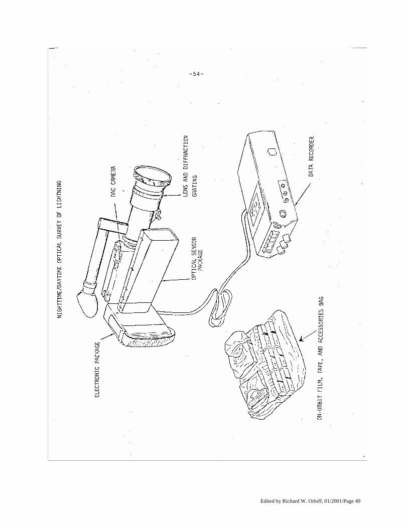
Edited by Richard W. Orloff, 01/2001/Page 49
Edited by Richard W. Orloff, 01/2001/Page 50
During passages over the dark side of the Earth, the astronaut observers will readily recognize nocturnal storms by their lightning flashes, which should be visible for hundreds of kilo-meters. On the sunlit side of the Earth, the crew
will recognize storms through prior familiarization with the appearance of cumulonimbus clouds and associated characteristic shapes as viewed from above.
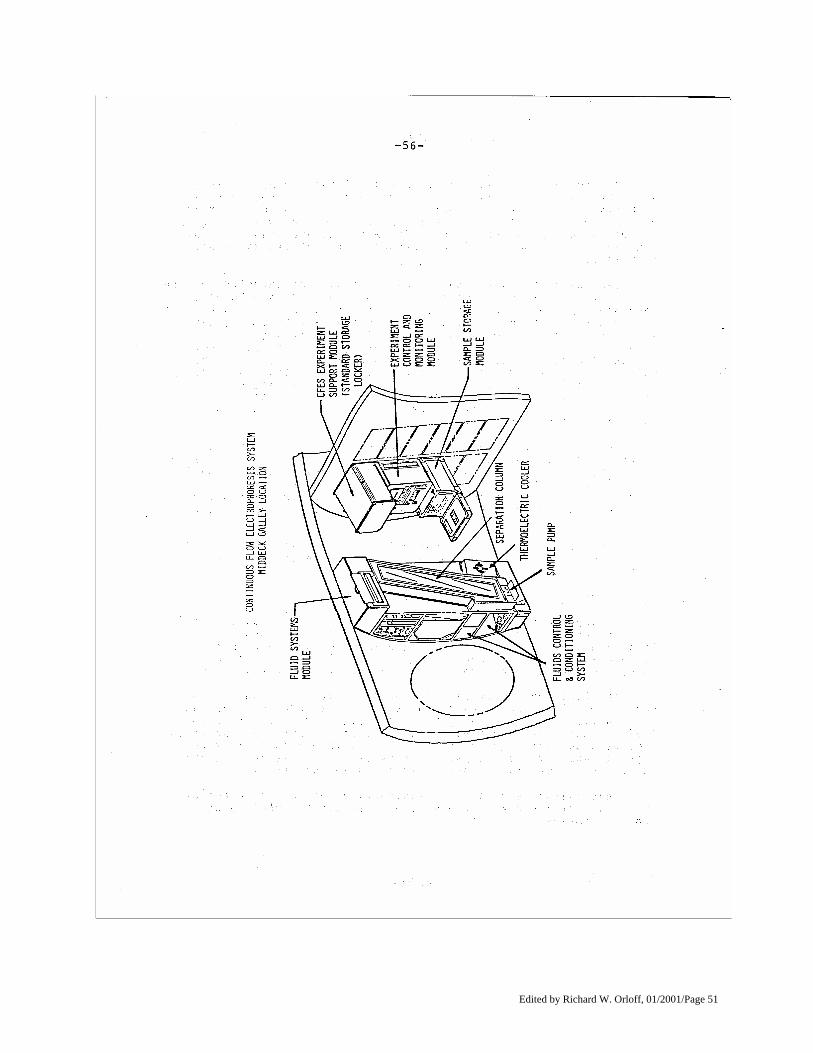
Candidate storms for this experiment will be targeted for the astronauts by a team of scientists at Marshall's Space Sciences Laboratory using a sophisticated developmental weather system called McIDAS, the Man computer Interactive Data Access System. When a potential storm is identified along the projected track path of the Orbiter, the coordinates are given to Mission Control so that the astronauts will be alerted at the appropriate time. McIDAS is a NASA and NOAA (National Oceanic and Atmospheric Administration) sponsored system based at the University of Wisconsin in Madison, which furnishes the Marshall Center team and other research groups with a mix of vast amounts of ground data and satellite weather information. When a target is in view, a crew member will use the camera to photograph through the windows of the crew cabin. The observer will locate the storm clouds and record his observations. During the filming of the storm clouds, signals corresponding to camera shutter pulses will be recorded on one track of the stereo tape recorder and the photocell output will be recorded on the other track. Otha H. Vaughan Jr., of Marshall's Space Sciences Laboratory, and Dr. Marx Brook, of the New Mexico Institute of Mining and Technology, Socorro. are co-investigators. Continuous Flow Electrophoresis System An experiment which marks the first use of the Space Shuttle by a commercial concern will be carried into space aboard STS-4. This flight also introduces a unique NASA concept to promote the advancement of space technology and the utilization of space through partnership arrangements with private enterprise. The Continuous Flow Electrophoresis System, nicknamed "Eos" (Greek god of the dawn) by its developer, the McDonnell Douglas Astronautics Co., St. Louis, Mo., is designed to separate biological materials according to their surface electrical charge as they pass through an electric field. Unlike previous electrophoresis experiments in space, the system processes considerable quantities of materials carried in a continuous stream. This flight is an initial engineering test of the electrophoresis system hardware and will process six McDonnell Douglas protein samples.
Edited by Richard W. Orloff, 01/2001/Page 51
Edited by Richard W. Orloff, 01/2001/Page 52
The environment of space offers advantages for electrophoresis processes over Earth-based separation. Earth's gravity limits this process in several ways. Gravity limits the concentration of the materials in the sample being separated, which is one of the primary factors limiting the electrophoresis production of commercial quantities on Earth. On Earth, only 0.25 percent of the sample to be separated can be biological material. The rest must be carrier fluid. In space, however, the concentration can be increased to 20 percent or more of the total sample, which increases the output of the process by a factor of 80 to 100 over Earth processing. Also on Earth, the sample stream size must be restricted to minimize gravity-induced disturbances. On Earth the stream may measure only one-half millimeter in diameter, while in space the sample stream diameter may be increased to one millimeter. This increases the output of the process by a factor of four, and when combined with the increase from higher concentrations, can result in an overall increase in output of 300 to 400 times when compared to an Earth-based unit. Purer materials can be obtained in space. On Earth, heat caused by the electric current used in the separation process induces convection, which reduces the purity of the separated materials. In space, the voltage may be increased without causing disturbing convective flows. Also, in space the length of time that the material being separated is in the electric field may be increased without detrimental side effects. This, in conjunction with the increased voltage, can significantly improve the purity of the separated materials. Scientists from the Ortho Pharmaceutical Div. of Johnson & Johnson, the company collaborating with McDonnell Douglas in this effort, investigated the potential of several candidate space products. They report that a small quantity of each separated material would satisfy a reasonable share, or about 25 percent, of the available market for those products. NASA is flying this experiment under a "joint endeavor agreement," pioneered and managed for NASA by the Materials Processing in Space Projects Office at the Marshall Space Flight Center. Under such an agreement, private enterprise and NASA work together as partners to promote the utilization of space where a technological advancement is needed and there is a potential commercial application. Joint endeavors are designed to contribute directly to NASA's scientific objectives in the field of materials processing in low gravity and to simultaneously accelerate the benefits to the general public from this emerging technology. In this experiment, both McDonnell Douglas and NASA will benefit from the use of this equipment for space experimentation in materials science. Under terms of the agreement with McDonnell Douglas, flight time on the Shuttle orbiter is furnished to McDonnell Douglas during the developmental phase of the electrophoresis device, starting with this mission. NASA, in turn, gets experiment opportunities using the device, and equipment performance data which will expand the base of knowledge in the field of separation sciences. McDonnell Douglas will commercialize any promising results from the work and make it available to the U.S. public on reasonable terms and conditions. General equipment performance data and the results from NASA's experiments using the electrophoresis system device will be made public. Scientists at Marshall and Johnson Space Centers will conduct NASA's experiments on the device. During the next two years, the electrophoresis system will be carried into space in the mid deck area of the Shuttle orbiter on six space flights. Provided these experimental operations prove successful, plans call for a larger electrophoresis unit to be carried in the cargo bay on two future Shuttle flights. According to conditions of the joint agreement, McDonnell Douglas has the option of attaching the unit to a NASA orbiting space platform in 1986 should such a platform be in operation.
Edited by Richard W. Orloff, 01/2001/Page 53
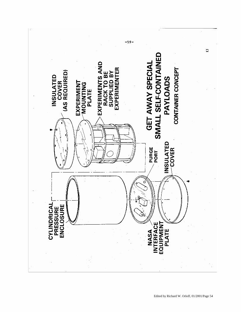
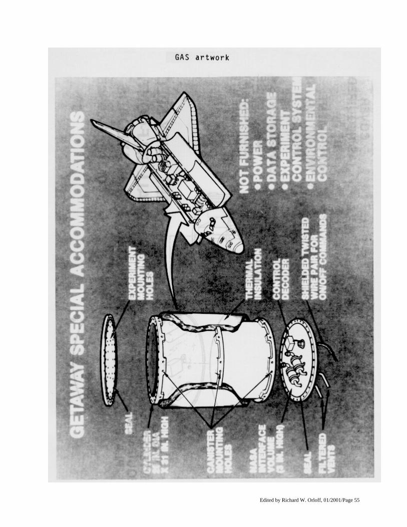
GETAWAY SPECIAL Officially titled Small Self-Contained Payloads, the Getaway Special program is offered by NASA to provide anyone who wishes the opportunity to fly a small experiment aboard the Space Shuttle. The experiment must be of a scientific research and development nature. A Getaway Special Flight Verification Payload flew aboard the STS-3 mission. The test payload, a cylindrical canister .6 m (2 ft.) in diameter and .9 m (3 ft.) deep, measured the environment in the canister during flight. The data were recorded and will be analyzed for use by Getaway Special experimenters on future Shuttle missions. The Getaway Special experiments will be flown on Shuttle missions on a space-available basis. The first private sector payload is being flown on STS-4. This payload was purchased by Gilbert Moore and donated to Utah State University where it is being used as a program for student constructed experiments. All nine experiments will be contained in the 5-cubic-foot payload canister.
Edited by Richard W. Orloff, 01/2001/Page 54
Edited by Richard W. Orloff, 01/2001/Page 55
Edited by Richard W. Orloff, 01/2001/Page 56
Experiment Science Descriptions for First Getaway Special Drosophilae Melanogaster (Fruit Fly) Growth Experiment Student Investigator: Walt L. Moore, HDR Sciences Co., Santa Barbara, Calif., graduate/environmental sciences. This experiment is designed to provide a means of raising and separating succeeding generations of fruit flies, Drosophilae Melanogaster, in orbit to study the effects of microgravity on their genetic structure. This will be a test of equipment that is proposed to be flown on the Long Duration Exposure Facility. Artemia (Brine Shrimp) Growth Experiment Student Investigator: Bruce W. Moore, Weber State College, Ogden, Utah, freshman/music. The brine shrimp Artemia will be flown to determine the genetic effects of microgravity on cysts hatched in space. Cysts will be injected into a saline solution upon experiment activation. The growing shrimp, called nauplii, will be observed during the remainder of the flight with a 35 mm motor-driven Nikon camera with a 55 mm micro-Nikkor lens. The camera will be shared between this experiment and another experiment concerning observations of Duckweed growth in microgravity. Powdered rice hulls will be fed to the shrimp by a linear actuator. The shrimp will be studied postflight with electron microscopy. Surface Tension Experiment Student Investigator: James Elwell, Utah State University, Ogden. graduate/electrical engineering. The goal is to study the shape of a liquid meniscus in a weightless environment. An aluminum block contains several holes filled with solder. Upon entering weightlessness, the block is heated, allowing the solder to flow and assume a meniscus shape. The block is allowed to cool, "freezing" the meniscus when the snider solidifies. Composite Curing Experiment Student Investigator: Amber M. Dalley, Utah State University, Ogden, senior/math-philosophy. This experiment will complete the cure of a B-staged (partially cured) epoxy resin-graphite composite sample in microgravity. The composite sample will be heated to 163 degrees C and maintained at that temperature for one-half hour to allow the resin to gel. The flight sample will be compared with samples processed in one G and post flight laboratory analysis will determine the quality of wetting between the resin and the graphite fibers and test the tensile strength of the sample. Thermal Conductivity Experiment Student Investigator: Russel R. Laher, Utah State University, Ogden, junior/physics-geology. An oil and water mixture in a one G environment will separate due to the density difference. The goal of the experiment is to carry oil and water into orbit and mix the two, then heat the mixture with a platinum wire. Temperatures of the heater wire, the mixture, and the air around the cylinder will be monitored. Ultimately, the thermal conductivity of the mixture will be calculated from these data.
Edited by Richard W. Orloff, 01/2001/Page 57
Microgravity Soldering Experiment Student Investigator: G. Christian Alford, Utah State University, Ogden, senior/electrical engineering. The Microgravity Soldering Experiment studies the separation of flux from solder while soldering in weightlessness. The lack of buoyancy in a non-accelerating environment could allow pockets of flux to become trapped in the solder. The experiment will melt samples of resin core and coreless solder on four heated copper foils. When the experiment is returned, the solder will be analyzed for trapped pockets of flux and compared with solder similarly processed on Earth. Root Growth of Lemna Minor L. (Duckweed) in Microgravity Student Investigator: Kelly D. Hunt, Utah State University, Ogden. junior/physics. Using the 35 mm Nikon, shared with the experiment described earlier, this experiment will photograph the root growth patterns of Lemna Minor L. (duckweed). The investigation centers on the nutrient transport role played by sieve tubes in the plants' roots in response to the force of gravity in Earth-grown specimens. The plants will be injected with a fixing agent before experiment deactivation. Electron microscopy will be used to compare control and flight specimens. Homogeneous Alloy Experiment Student Investigator: Terrance L. Thomas, Utah State University, Ogden, junior/electrical engineering. An aluminum chamber containing a powdered bismuth-tin mixture will be placed into Earth orbit. The chamber will be heated, passing the melting points of the chemicals and allowing alloying to take place. The chamber will cool down and the alloy will be returned for Earth-based analysis. Algal Microgravity Bioassay Experiment Student Investigator: Steven M. Walker, Utah State University, Ogden, senior/biology. The goal of the experiment is to monitor the growth rate of Chlorella vulgaris, a unicellular green algae, in microgravity. Upon experiment activation, a freeze-dried sample of algae will be injected into the media-filled growth chamber. Over the duration of the experiment the culture optical density and temperature will be measured. Near the end of this experiment, a fixative will be injected into the chamber preserving the cells for postflight analysis. The Getaway Specials are available to industry, educational organizations and domestic and foreign governments for legitimate scientific purposes. Since the offer for Space Shuttle space first was made in 1976, more than 32O reservations have been made by more than 191 individuals and groups from 33 states, the District of Columbia and 14 foreign nations. Although many reservations have been obtained by persons and groups having an obvious interest in space research, a large number of spaces have been reserved by persons and organizations entirely outside the space community. Reservations are held, for example, by Realtors, bankers, newspaper publishers, and school children, among others, who have an interest in conducting experiments in biology, chemistry, Earth science, physics and other disciplines. Examples include an inner city high school class in Camden, N. J., which intends to fly an ant colony in space to determine the effect of weightlessness on the ants, and a Japanese newspaper, the Asahi Shimbun, is planning a snow-making experiment under zero-G conditions to investigate crystallization.
Edited by Richard W. Orloff, 01/2001/Page 58
There are no stringent requirements to qualify for space flight, but the payload does have to meet safety criteria. It must also have a scientific or technological objective. For example, a manufacturer may want to test, on a priority basis, a certain type of metal-making in space for later use in his own production. This is not only permissible, but welcome. However, a person who wishes to fly items of a commemorative nature, such as medallions for later resale as "objects that have flown in space" would be refused. While payloads must be related to a technical or scientific objective, NASA will not attempt to judge their scientific merit or novelty. Getaway Special requests must first be approved at NASA Headquarters, Washington, D.C. It is at this point that requests for Shuttle space are screened for propriety, and scientific or technical aim. These requests must be accompanied or preceded by the payment of $500 earnest money. Requests approved by NASA are given a payload identification number and referred to the Getaway Special Team at NASA's Goddard Space Flight Center, Greenbelt, Md. The Getaway Special Team screens the proposal for safety and provides advice and consultation for payload design. Shuttle crew members will turn on and off up to three payload switches, but there will be no opportunity for crew monitoring of Getaway Special experiments, or for any form of inflight servicing. The Getaway Special Team must certify that the proposed payload is safe -- meaning that it will not harm or interfere with the operations of the Shuttle, its crew or other experiments on the flight. If any physical testing must be done on the payload to answer safety questions prior to the launch, the expense of these tests must be borne by the customer. Getaway Special spaces come in three standard sizes: 5 cu. ft., with a maximum of 91 kg (201 lb.); 2 1/2 cu. ft. and up to 45 kg (100 lb.); and 2 1/2 cu. ft. and up to 27 kg (60 lb.). The prices for flying these are $10,000, $5,000 and $3,000 respectively. These prices will remain fixed for the first three years of Shuttle operations. The Getaway Special program is managed by the Goddard Space Flight Center. Project Manager is James S. Barrowman. Clarke Prouty, also of Goddard, is technical liaison officer. Program Manager at NASA Headquarters, Washington, D.C. is Donna S. Miller.
SHUTTLE STUDENT INVOLVEMENT PROJECT The Shuttle Student Involvement Project is a joint venture of NASA and the National Science Teachers Association. The project is designed to stimulate the study of science and engineering by engaging students in grades 9 through 12 in a competition to develop proposals suitable for flight aboard the Shuttle. The 10 winners of the first competition were announced in May 1981. NASA then paired each student with a corporate sponsor and a NASA consultant to assist the student in turning the proposal into a flight ready project. The 20 winners of the second competition were announced in May 1982 and the third competition will begin in September of this year. Two winning entries from the first competition will fly aboard STS-4. Both experiments are medical in nature and required no hardware preparation. "The Effects of Diet, Exercise, and Zero Gravity on Lipoprotein Profiles," was proposed by Amy Kusske, 16, Wilson High School, Long Beach, Calif. This project will document the diet and exercise program for the astronauts pre and postflight.
Edited by Richard W. Orloff, 01/2001/Page 59
There are several types of lipoproteins in the blood. The ratio between these -- particularly high density lipoproteins (HDL) and low density lipoproteins (LDL) -- can be used to predict the likelihood of someone developing arteriosclerosis. Arteriosclerosis and coronary disease are diseases of epidemic proportions in the United States. Exercise increases the HDL/LDL ratio, decreasing the risk factor for arteriosclerosis and coronary artery disease. The goal of Amy's research is to determine whether any alterations occur in lipoprotein profiles during space flight. During the mission, the astronauts will record on log cards what is and what is not consumed in their diet. The astronauts will keep a similar diary of their exercise performance and how that exercise is maintained. To measure the crew's lipoprotein profiles, blood samples will be collected during scheduled physical examinations approximately seven and two days before flight and upon touchdown. Analysis of these samples will be done at Johnson Space Center's Biochemical Laboratories. The results will be provided to Amy for interpretation. Corporate sponsor for this experiment has been McDonnell Douglas Astronautics Co. Dr. William Douglas of McDonnell's Huntington Beach facility has worked with Amy. The NASA consultant for this experiment is Dr. Carolyn Huntoon, of Johnson's Biomedical Laboratories. Mrs. Linda Sanders of Lakewood High School is Amy's teacher-advisor. A second student project on STS-4 is "The Effects of Space Travel on Levels of Trivalent Chromium in the Body." Developed by Karla Hauersperger, 17, from East Mecklenburg High School, Charlotte, N.C., this project hopes to determine whether any alterations occur in chromium metabolism during space flight. Serum levels of insulin are known to change slightly during space flight, and insulin helps control body use of carbohydrates. Chromium is a cofactor (that is, a substance which must be present in low quantities for an enzyme to work) for insulin. To carry out the project the food which the crew eats will be recorded, and the chromium content determined by use of U.S. Department of Agriculture computer-feed reference values. During flight, the crew will record on log cards how much they eat of what foods (these will be same cards for the other student project). To measure crew levels of serum glucose, insulin, chromium and urine chromium, blood and urine samples will be collected during scheduled physical examinations approximately seven and two days before flight and upon touchdown. Analysis of these samples will be done by Johnson's Biomedical Laboratories and results will be provided to Karla for interpretation. Levels of trivalent chromium will be determined by atomic absorption spectrophotometry. Karla's corporate sponsor was the Explorer's Club of New York City. Dr. Huntoon of Johnson helped Karla develop the project. Mrs. Wilma Collins, East Mecklenburg High School, was Karla's teacher-advisor.
ORBITER EXPERIMENTS PROGRAM A complete and accurate assessment of Shuttle performance during the launch, boost, orbit, atmospheric entry and landing phases of a mission requires precise data collection to document the Shuttle's response to these conditions. The NASA Office of Aeronautics and Space Technology (OAST), through its Orbiter Experiments Program, is providing research experiments onboard the Shuttle orbiter to record specific, research-quality data. The data will verify the accuracy of wind tunnel and other ground-based simulations made prior to flight; verify ground-to-flight
Edited by Richard W. Orloff, 01/2001/Page 60
extrapolation methods, and verify theoretical computational methods. The data also will be useful to the Office of Space Transportation Systems to further certify Shuttle and expand its operational envelope. The primary objective of the Orbiter Experiments Program is to increase the technology reservoir for development of future (21st Century) space transportation systems. The following experiments are currently included in the program and are slated to fly on early Shuttle flights. Aerodynamic Coefficient Identification Package (ACIP) The primary objectives of the Aerodynamic Coefficient Identification Package are: • To collect aerodynamic data during the launch, entry and landing phases of the Shuttle; • To establish an extensive aerodynamic data base for verification of the Shuttle's aerodynamic performance and
the verification and correlation with ground-based data, including assessments of the uncertainties of such data; • To provide flight dynamics data in support of other technology areas. such as aerothermal and structural
dynamics. The ACIP system has now flown on STS-1, 2 and 3. It will fly again on STS-4 and current plans call for continued operation on future Shuttle flights, including the operation of a second ACIP unit on OV-099. Instruments in this package include dual-range linear accelerometers and rate gyros. Also included are the power conditioner for the gyros, the power control system and the housekeeping components. The package is installed co-linearly with the geometric axes of the orbiter and post-installation measurements made to establish the position within 10 arc minutes. The instruments continuously sense the dynamic X, Y and Z attitudes and performance characteristics of the orbiter through these critical flight phases. The Aerodynamic Coefficient Identification Package also provides high rate sampling of the positions of orbiter control surfaces for recording with the package's attitude data. Principal technologist is D.B. Howes of Johnson Space Center, Houston. Infrared Imagery of Shuttle (IRIS) This experiment will obtain high-resolution infrared imagery of the orbiter lower (windward) and side surfaces during reentry from which surface temperatures and hence aerodynamic heating may be inferred. The imagery will be obtained utilizing a 91.5-cm (36-in.) telescope mounted in the NASA C-141 Gerard P. Kuiper Airborne Observatory positioned appropriately at an altitude of 13,700 m (45,000 ft.) along the entry ground track of the orbiter. A single image will be obtained during each flight. On the STS-3 mission the IRIS experiment successfully obtained an image of the Shuttle during the transition phase of the entry. The image was obtained at 16.5 minutes after Entry Interface, when the Shuttle was at an altitude of 54,860 m (180,000 ft.) and flying at a Mach 15. During the STS-4 mission, the Kuiper Airborne Observatory will be deployed from Hickam Air Force Base, Hawaii, to image the Shuttle during the peak heating phase. This will occur at an altitude of approximately 64,000 m (210,000 ft.), while flying at Mach 21. The primary technology objective is to decrease the current level of uncertainty associated with various reentry aerothermodynamic phenomena affecting thermal protection system design. The phenomena include boundary layer transition, flow separation and reattachment, flow/surface interactions and surface catalyses to flow chemistry.
Edited by Richard W. Orloff, 01/2001/Page 61
These data will provide for improved computational procedures and lead to development of advanced thermal protection systems. The infrared imagery system consists of the C-141 aircraft and its optical system, a 6-cm (2-in.) aperture acquisition telescope focal plane system with detector array, and a high-speed data handling and storage system. The aircraft will operate from Ames Research Center, Mountain View, Calif., and will be stationed along the orbiter entry ground track about one hour prior to reentry. As the orbiter passes through the field of view of the telescope, the orbiter windward or side surface will be observed by the detector system and the data recorded on tape. After the flight, these data will be supplemented by orbiter-derived data of velocity, altitude, angle-of-attack, yaw and roll conditions existing during the period of infrared imagery observation. Analysis involves computer arrangement of this data into a two-dimensional image format, radiometric analysis and detailed comparisons of the aerodynamic heating rates with analytical predictions and ground-based experimental data. Principal technologist is W.C. Davy, Ames Research Center. Tile Gap Heating Effects (TGH) Experiment Analyses and ground tests have shown that the gaps between the tiles of the thermal protection system generate turbulent airflow, which will cause increased heating during the reentry phase of flight. Tests have also shown that the heating effect may be reduced by optimum design of the gaps and by altering the radii at the edges of the tiles. The tile gap experiment was devised to further the investigations of heating phenomena. The results will enable improvements in reusable element thermal protection systems to reduce the convective heating caused by gaps an d other discontinuities. The orbiter will be instrumented with a removable panel 45.7 cm (18 in.) square, which will carry 11 tiles of baseline material and size. The panel will be fitted to the underside of the orbiter fuselage. The gaps between tiles will be carefully calculated and controlled during fitting to ensure that the heating rates generated during entry will be no higher than those of the baseline tile array. The aim will be to produce a design that will result in heating rates lower than those of the baseline system. In addition to gap spacing, the gap depth will also be controlled through the use of fillers fitted at the bottom of certain gaps; i.e., at the junction of the tiles and the orbiter fuselage skin. The radii at the outer edges of the tiles will be controlled during fabrication to conform to calculations that show the reduced effects in combination with the spacing. Thermocouples will be fitted to the tile surfaces and at various depths in the gaps to measure temperatures during reentry. The output of the thermocouples will be recorded on the orbiter's development flight instrumentation system. To assist in evaluation, Tile Gap Heating Effects data will be compared to development flight instrumentation data obtained from earlier missions. This will be the third flight of the experiment which successfully flew on STS-2 and 3. On STS-4 it will be modified to investigate the effect of tile gap geometry on gap filler bar heating. The STS-4 test configuration is co-sponsored by the Orbiter Experiments Project and the Orbiter Project. Information provided by this test will aid the Orbiter Project in the evaluation filler bar heating experienced on STS-1, 2 and 3. Principal technologist is W. Pitts, Ames Research Center.
Edited by Richard W. Orloff, 01/2001/Page 62
Catalytic Surface Effects (CSE) Experiment A strong shockwave will encompass the Shuttle orbiter during the atmospheric reentry maneuver. The shock wave severely compresses and heats the air flowing through it, causing the molecules to dissociate and react chemically with each other. Computations show that as the dissociated atomic oxygen approaches the cooler regions of flow adjacent to the orbiter, the atomic oxygen fails to recombine into molecular oxygen. This experiment will investigate the chemical reaction caused by impingement of atomic oxygen on the Shuttle thermal protection system which was designed under the assumption that the atomic oxygen would recombine at the thermal protection system wall. This chemical reaction releases additional heat which results in higher thermal protection system temperatures. In this case, the surface is referred to as being a catalytic surface, that is, it allows the chemical reaction to take place. If the thermal protection system surface is non-catalytic, then atomic oxygen will not recombine into molecular oxygen and the heating rates will be lowered. Thus, the temperature of the orbiter during reentry will be lower. With lower temperatures, orbiter thermal protection system weight could be reduced, its flight envelope could be expanded, or greater reusability could result. The technology objective is to verify analytical predictions which could not be adequately simulated in ground-based facilities. The results will provide data and improved computational techniques for future thermal protection system designs. The Catalytic Surface Effects will use baseline tiles, selected from those having development flight instrumentation thermocouples, located on or near the orbiter lower fuselage centerline. The five tiles will be sprayed with an overcoating mixture of chrome-iron-spinel, a highly efficient catalytic material and a vinyl acetate binder which will protect the overcoat during ground operations. The mixture is compatible with the existing tile and coating and will not alter the thermal or mechanical properties of the uncoated portions of the thermal protection system. During orbiter ascent, the vinyl acetate will burn off the tile surface, leaving the chrome-iron-spinel exposed. Thermocouple measurements recorded during reentry will be used to determine Catalytic Surface Effects performance. Comparison of this experiment's data with data taken on previous flights from uncoated tiles will aid in the performance evaluation. This will be the third flight of the experiment. Data collected on the STS-2 and 3 has been useful in verifying the preflight predictions that the tile surfaces are non-catalytic. At the end of each mission, the overcoat will be removed from the six tiles, leaving the thermal protection system in its original condition. Principal technologist is D. Stewart, Ames Research Center. Dynamic, Acoustic and Thermal Environment (DATE) Experiment To fully and economically exploit the benefits of the orbiter's large cargo-carrying capability, it is necessary to predict payload environments with accuracy and dispatch. Such predictions will facilitate payload development and reduce the need for ultraconservative design and test. The Dynamic, Acoustic and Thermal Environment experiment will collect information for use in making credible predictions of cargo-bay environments. These environments are neither constant nor consistent throughout the bay and are influenced by interactions between cargo elements.

Edited by Richard W. Orloff, 01/2001/Page 63
The instrumentation includes accelerometers, microphones, thermocouples and strain gages on payloads and in the cargo bay. Sensor outputs will be recorded for post-flight interpretation. DATE instrumentation has successfully flown on STS-1, 2 and 3. The Goddard Space Flight Center, Greenbelt, Md., will be responsible for the data reduction. Principal technologist is W. Bangs of Goddard.
Edited by Richard W. Orloff, 01/2001/Page 64
ORBITER'S ROBOT "ARM" (Remote Manipulator System)
Columbia is fitted with a Canadian-built remote manipulator system which was tested during STS-2 and STS-3. Part of the payload deployment and retrieval system, the mechanical arm will be used in operational flights to deploy satellites and other payloads or to grapple payloads for stowing in the payload bay and subsequent return to Earth. Designed as an analog to the human arm, the manipulator system has shoulder, elbow and wrist joints driven by DC electric motors controlled by the flight crew using a combination of direct observation and television cameras on the elbow and wrist joints. The arm may be operated in five different modes ranging from full manual to computer-controlled through hand controls and keyboard at the payload station on the flight deck. The manipulator system is installed on the left payload bay longeron for STS-4. A second one can be installed on the right longeron for specific payload tasks, although both arms could not operate simultaneously. The arm, built of a light-weight carbon composite tubing 38 cm (15 in.) in diameter, is 15.3 m (50.25 ft.) long, and weighs 408 kg (900 lb.). A thermal blanket and heater provide temperature control for protecting joint-drive mechanisms and electronics. Brushless electric motors and gear trains drive the joints for pitch up/down, yaw left/right and wrist roll motions. The "hand," called an end effector, has snare wires that engage a grapple fixture on the payload. Operator hand controllers are similar to those for spacecraft maneuvers -- a rotational hand controller for roll, pitch and yaw motions, and translational hand controller for up/down, left/right and fore/aft motions. When deactivated, the arm is latched into three cradle pedestals along the left longeron. If the drive mechanisms jam and the arm cannot be moved to its stowed position, and if contingency spacewalks are unsuccessful in restowing, the arm can be amputated with a pyrotechnic device. The five arm operating modes are as follows: • Automatic -- Operators select autosequence loaded into general purpose computer software which then moves
arm through sequence; or, operator enters desired position coordinates into computer with keyboard at operator's station.
• Manual augmented -- Operator drives arm end effector with hand controllers without controlling individual
joint motions. • Manual single joint drive -- Operator drives arm through control panel switches on a joint-by-joint basis. • Direct drive -- Operator controls motion through hardwired command from control panel that bypasses the
general purpose computer. • Backup drive control -- Essentially same as direct drive, only commands pass through backup electronics and
wiring. The arm was developed and built under a cooperative agreement between NASA and the National Research Council of Canada. Spar Aerospace Ltd. is system prime contractor. Canada has absorbed the costs of research and development of the first arm installed aboard Columbia. The ability of the arm to handle payloads in orbital flight can be tested on the ground only to a limited degree. Before full-scale heavy mass and large-volume payloads can be moved in and out of the payload bay, smaller, lighter objects are being handled to gain confidence in the design and to gain experience in operating the arm. The induced environment contamination monitor serves as a simulated payload during STS-4 arm testing.
Edited by Richard W. Orloff, 01/2001/Page 65
Systems testing of the remote arm are aimed toward verifying that the arm, its computer software, closed-circuit television and crew visual cues all mesh for smooth and reliable operation. STS-4 arm tests are grouped under five basic test objectives: • Deploy and berth the contamination monitor with the remove arm. • Grapple, rigidize and release the contamination monitor grapple fixture with the arm's end effector, or hand. • Verify that the software will bring an arm joint to stop before its travel limit is reached. • Demonstrate the arm's ability to hold position during reactor control system thruster activity. • Test the software's ability to move the arm elbow joint in manual control mode.
HUNTSVILLE OPERATIONS SUPPORT CENTER The Huntsville Operations Support Center is a facility at the Marshall Space Flight Center in Huntsville, Ala., which provides launch support to Kennedy Space Center and payload operation support to Johnson Space Center. During pre-mission, countdown, launch and powered flight toward orbit, Marshall and contractor engineers, development project managers and their contractors are on consoles in the support center to monitor real-time data being transmitted from the Shuttle. Their purpose is to evaluate and help solve problems that might crop up with Marshall-developed Shuttle elements, including the Space Shuttle main engines, external tank and solid rocket boosters. They also are concerned with problems in the overall main propulsion system and range safety system. The data, which provide information on the "health" of these systems, are gathered by sensors aboard the Shuttle and are instantaneously transmitted from the launch site to the support center. There the information is processed by computers and displayed on screens and other instruments at 12 stations in the engineering console room. More than 3,000 temperature, pressure, electrical voltage and other measurements are made every second. During the 10 hours of peak activity before and during launch, more than 11 million measurements are assessed by teams of experts. Support center personnel will view the Shuttle on the launch pad via two closed circuit television lines. They also have access to more than 25 direct communications lines that link them with the launch site at Kennedy Space Center, Mission Control Center at Johnson and with responsible contractor plants. In addition to launch support, payload services will be provided by teams of scientists operating out of specially equipped payload support rooms. During this flight, two co-investigators on the Monodisperse Latex Reactor will operate in the support center to evaluate the function of the experiment and monitor the astronautic-experiment operations during televised hardware use. The Induced Environment Contamination Monitor scientific team will monitor and evaluate the electrical function of the instrument package during its normal operation. The team will also monitor contamination mapping of the cargo bay and a plume pressure test. Other payload assistance is provided for the Nighttime/ Daytime Optical Survey of Lightning. Scientists in the Huntsville center will monitor flight crew voice transmissions to coordinate on-orbit use of experiment hardware with the principal investigator, located at Johnson.
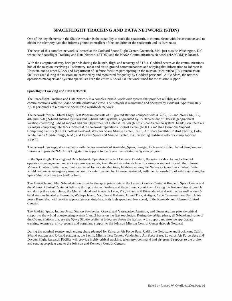
Edited by Richard W. Orloff, 01/2001/Page 66
SPACEFLIGHT TRACKING AND DATA NETWORK (STDN) One of the key elements in the Shuttle mission is the capability to track the spacecraft, to communicate with the astronauts and to obtain the telemetry data that informs ground controllers of the condition of the spacecraft and its astronauts. The heart of this complex network is located at the Goddard Space Flight Center, Greenbelt, Md., just outside Washington, D.C. where the Spaceflight Tracking and Data Network (STDN) and the NASA Communications Network (NASCOM) is located. With the exception of very brief periods during the launch, flight and recovery of STS-4. Goddard serves as the communications hub of the mission, receiving all telemetry, radar and air-to-ground communications and relaying that information to Johnson in Houston, and to other NASA and Department of Defense facilities participating in the mission. Most video (TV) transmission facilities used during the mission are provided by and monitored for quality by Goddard personnel. At Goddard, the network operations managers and systems specialists keep the entire NASA/DOD network tuned for the mission support. Spaceflight Tracking and Data Network The Spaceflight Tracking and Data Network is a complex NASA worldwide system that provides reliable, real-time communications with the Space Shuttle orbiter and crew. The network is maintained and operated by Goddard. Approximately 2,500 personnel are required to operate the worldwide network. The network for the Orbital Flight Test Program consists of 15 ground stations equipped with 4.3-, 9-, 12- and 26-m (14-, 30-, 40- and 85-ft.) S-band antenna systems and C-band radar systems, augmented by 15 Department of Defense geographical locations providing C-band support and one Department of Defense 18.3-m (60-ft.) S-band antenna system. In addition, there are six major computing interfaces located at the Network Operations Control Center (NOCC) and the Operations Support Computing Facility (OSCF), both at Goddard; Western Space Missile Center, Calif.; Air Force Satellite Control Facility, Colo.; White Sands Missile Range, N.M.; and Eastern Space and Missile Center, Fla., providing real-time network computational support. The network has support agreements with the governments of Australia, Spain, Senegal, Botswana, Chile, United Kingdom and Bermuda to provide NASA tracking stations support to the Space Transportation System program. In the Spaceflight Tracking and Data Network Operations Control Center at Goddard, the network director and a team of operations managers and network systems specialists, keep the entire network tuned for mission support. Should the Johnson Mission Control Center be seriously impaired for an extended time, facilities serving the Network Operations Control Center would become an emergency mission control center manned by Johnson personnel, with the responsibility of safely returning the Space Shuttle orbiter to a landing field. The Merritt Island, Fla., S-band station provides the appropriate data to the Launch Control Center at Kennedy Space Center and the Mission Control Center at Johnson during prelaunch testing and the terminal countdown. During the first minutes of launch and during the ascent phase, the Merritt Island and Ponce de Leon, Fla., S-band and Bermuda S-band stations, as well as the C-band stations located at Bermuda; Wallops Island, Va.; Grand Bahama; Grand Turk; Antigua; Cape Canaveral; and Patrick Air Force Base, Fla., will provide appropriate tracking data, both high speed and low speed, to the Kennedy and Johnson Control Centers. The Madrid, Spain; Indian Ocean Station Seychelles; Orroral and Yarragadee, Australia; and Guam stations provide critical support to the orbital maneuvering system 1 and 2 burns on the first revolution. During the orbital phase, all S-band and some of the C-band stations that see the Space Shuttle orbiter at 3 degrees above the horizon will support and provide appropriate tracking, telemetry, air-to-ground and command support to the Johnson Mission Control Center through Goddard. During the nominal reentry and landing phase planned for Edwards Air Force Base, Calif.; the Goldstone and Buckhorn, Calif.; S-band stations and C-band stations at the Pacific Missile Test Center, Vandenberg Air Force Base, Edwards Air Force Base and Dryden Flight Research Facility will provide highly critical tracking, telemetry, command and air-ground support to the orbiter and send appropriate data to the Johnson and Kennedy Control Centers.
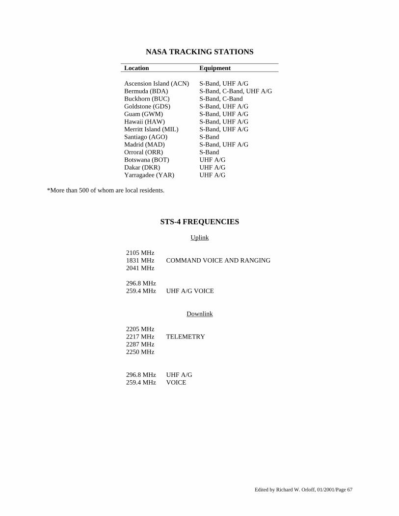
Edited by Richard W. Orloff, 01/2001/Page 67
NASA TRACKING STATIONS
Location Equipment Ascension Island (ACN) S-Band, UHF A/G Bermuda (BDA) S-Band, C-Band, UHF A/G Buckhorn (BUC) S-Band, C-Band Goldstone (GDS) S-Band, UHF A/G Guam (GWM) S-Band, UHF A/G Hawaii (HAW) S-Band, UHF A/G Merritt Island (MIL) S-Band, UHF A/G Santiago (AGO) S-Band Madrid (MAD) S-Band, UHF A/G Orroral (ORR) S-Band Botswana (BOT) UHF A/G Dakar (DKR) UHF A/G Yarragadee (YAR) UHF A/G
*More than 500 of whom are local residents.
STS-4 FREQUENCIES
Uplink
2105 MHz 1831 MHz COMMAND VOICE AND RANGING 2041 MHz 296.8 MHz 259.4 MHz UHF A/G VOICE
Downlink 2205 MHz 2217 MHz TELEMETRY 2287 MHz 2250 MHz 296.8 MHz UHF A/G 259.4 MHz VOICE
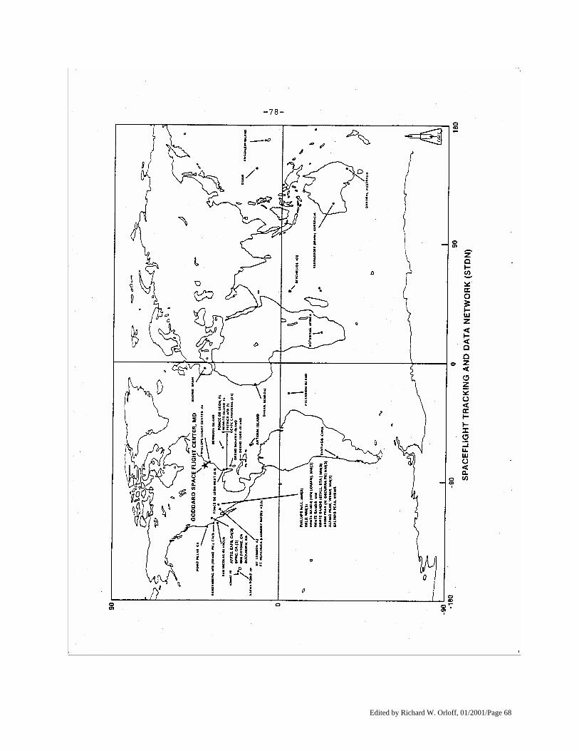
Edited by Richard W. Orloff, 01/2001/Page 68
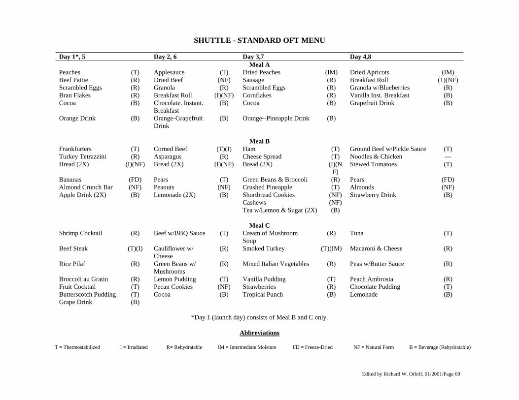
Edited by Richard W. Orloff, 01/2001/Page 69
SHUTTLE - STANDARD OFT MENU Day 1*, 5 Day 2, 6 Day 3,7 Day 4,8
Meal A Peaches (T) Applesauce (T) Dried Peaches (IM) Dried Apricots (IM) Beef Pattie (R) Dried Beef (NF) Sausage (R) Breakfast Roll (1)(NF) Scrambled Eggs (R) Granola (R) Scrambled Eggs (R) Granola w/Blueberries (R) Bran Flakes (R) Breakfast Roll (I)(NF) Cornflakes (R) Vanilla Inst. Breakfast (B) Cocoa (B) Chocolate. Instant.
Breakfast (B) Cocoa (B) Grapefruit Drink (B)
Orange Drink (B) Orange-Grapefruit Drink
(B) Orange--Pineapple Drink (B)
Meal B
Frankfurters (T) Corned Beef (T)(I) Ham (T) Ground Beef w/Pickle Sauce (T) Turkey Tetrazzini (R) Asparagus (R) Cheese Spread (T) Noodles & Chicken --- Bread (2X) (I)(NF) Bread (2X) (I)(NF) Bread (2X) (I)(N
F) Stewed Tomatoes (T)
Bananas (FD) Pears (T) Green Beans & Broccoli (R) Pears (FD) Almond Crunch Bar (NF) Peanuts (NF) Crushed Pineapple (T) Almonds (NF) Apple Drink (2X) (B) Lemonade (2X) (B) Shortbread Cookies (NF) Strawberry Drink (B) Cashews (NF) Tea w/Lemon & Sugar (2X) (B)
Meal C Shrimp Cocktail (R) Beef w/BBQ Sauce (T) Cream of Mushroom
Soup (R) Tuna (T)
Beef Steak (T)(I) Cauliflower w/ Cheese
(R) Smoked Turkey (T)(IM) Macaroni & Cheese (R)
Rice Pilaf (R) Green Beans w/ Mushrooms
(R) Mixed Italian Vegetables (R) Peas w/Butter Sauce (R)
Broccoli au Gratin (R) Lemon Pudding (T) Vanilla Pudding (T) Peach Ambrosia (R) Fruit Cocktail (T) Pecan Cookies (NF) Strawberries (R) Chocolate Pudding (T) Butterscotch Pudding (T) Cocoa (B) Tropical Punch (B) Lemonade (B) Grape Drink (B)
*Day 1 (launch day) consists of Meal B and C only.
Abbreviations
T = Thermostabilized I = Irradiated R= Rehydratable IM = Intermediate Moisture FD = Freeze-Dried NF = Natural Form B = Beverage (Rehydratable)
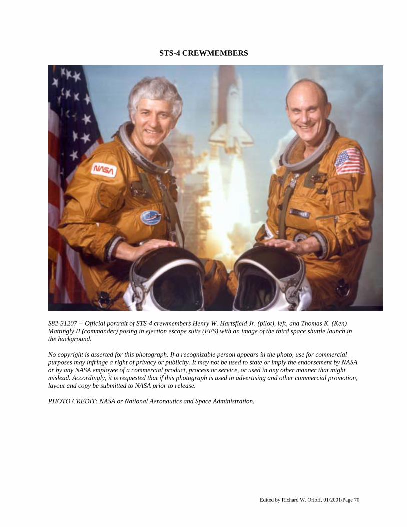
Edited by Richard W. Orloff, 01/2001/Page 70
STS-4 CREWMEMBERS
S82-31207 -- Official portrait of STS-4 crewmembers Henry W. Hartsfield Jr. (pilot), left, and Thomas K. (Ken) Mattingly II (commander) posing in ejection escape suits (EES) with an image of the third space shuttle launch in the background. No copyright is asserted for this photograph. If a recognizable person appears in the photo, use for commercial purposes may infringe a right of privacy or publicity. It may not be used to state or imply the endorsement by NASA or by any NASA employee of a commercial product, process or service, or used in any other manner that might mislead. Accordingly, it is requested that if this photograph is used in advertising and other commercial promotion, layout and copy be submitted to NASA prior to release. PHOTO CREDIT: NASA or National Aeronautics and Space Administration.
Edited by Richard W. Orloff, 01/2001/Page 71
BIOGRAPHICAL DATA NAME: Thomas K. Mattingly II (Captain, USN). STS-4 Commander, NASA Astronaut BIRTHPLACE AND DATE: Born in Chicago, Ill., March 17, 1936. His parents, Mr. and Mrs. Thomas K. Mattingly, now reside in Hialeah Fla. PHYSICAL DESCRIPTION: Brown hair; blue eyes; height: 5 feet 10 inches; weight: 140 pounds. EDUCATION: Attended Florida elementary and secondary schools and is a graduate of Miami Edison High School, Fla.; received a bachelor of science degree in Aeronautical Engineering from Auburn University in 1958. MARITAL STATUS: Single. CHILDREN: Thomas K. III, May 13, 1972. ORGANIZATIONS: Associate Fellow, American Institute of Aeronautics and Astronautics; Fellow, American Astronautical Society; and member, Society of Experimental Test Pilots, and the U.S. Naval Institute. SPECIAL HONORS: Presented the NASA Distinguished Service Medal, the JSC Certificate of Commendation (1970), the JSC Group Achievement Award (1972), the Navy Distinguished Service Medal and Navy Astronaut Wings, the Society of Experimental Test Pilots Iven C. Kincheloe Award (1972), the Delta Tau Delta Achievement Award (1972), the Auburn Alumni Engineers Council Outstanding Achievement Award (1972), the AAS Flight Achievement Award for 1972, the AIAA Haley Astronautics Award for 1973, and the Federation Aeronautique Internationale V. M. Komarov Diploma in 1973. EXPERIENCE: Prior to reporting for duty at the Lyndon B. Johnson Space Center, he was a student at the Air Force Aerospace Research Pilot School. Mattingly began his Naval career as an ensign in 1958 and received his wings in 1960. He was then assigned to VA-35 and flew A1H aircraft aboard the USS Saratoga from 1960 to 1963. In July 1963, he served in VAH-11 deployed aboard the USS Franklin D. Roosevelt where he flew the A3B aircraft for two years He has logged 6,300 hours of flight time -- 4,130 hours in jet aircraft. : NASA EXPERIENCE: Mattingly is one of 19 astronauts selected by NASA in April 1966. He served as a member of the astronaut support crews for the Apollo 8 and 11 missions and was the astronaut representative in development and testing of the Apollo spacesuit and backpack (EMU). He was designated command module pilot for the Apollo 13 flight but was removed from flight status 72 hours prior to the scheduled launch due to exposure to the German measles. Mattingly subsequently served as command module pilot of Apollo 16, April 16-27, 1972. He was accompanied on the fifth manned lunar landing mission by John W. Young (spacecraft commander) and Charles M. Duke Jr., (lunar module pilot). The mission assigned to Apollo 16 was to collect samples from the lunar highlands at a location near the crater Descartes. While in lunar orbit the scientific instruments aboard the command and service module "Casper" extended the photographic and geochemical mapping of a belt around the lunar equator. Twenty-six separate scientific experiments were conducted both in lunar orbit and during cislunar coast. Major emphasis was placed on using man as an orbital observer capitalizing on the human eye's unique capabilities and man's inherent curiosity. Although the mission of Apollo 16 was terminated one day early, due to concern over several
Edited by Richard W. Orloff, 01/2001/Page 72
spacecraft malfunctions, all major objectives were accomplished through the efforts of the mission support team and made possible by the most rigorous preflight planning associated with an Apollo mission. Mattingly has logged 265 hours and 51 minutes in space--1 hour and 13 minutes of which were spent in extravehicular activity (EVA). Mattingly worked as head of astronaut office support to the Space Transportation System program from January 1973 to March 1978. He was next assigned as technical assistant for flight test to the manager of the Orbital Flight Test Program. From December 1979 to April 1981, he headed the astronaut office ascent/entry group. He subsequently served as backup commander for STS-2 and STS-3, Columbia's second and third orbital test flights. CURRENT ASSIGNMENT: Mattingly is commander for STS-4, the fourth flight of the Shuttle orbiter Columbia.
Edited by Richard W. Orloff, 01/2001/Page 73
BIOGRAPHICAL DATA NAME: Henry W. Hartsfield Jr., STS-4 Pilot NASA Astronaut BIRTHPLACE AND DATE: Born in Birmingham, Ala., on Nov. 21, 1933. His mother, Mrs. Norma Hartsfield, resides in Birmingham, Ala. PHYSICAL DESCRIPTION: Brown hair; hazel eyes; height: 5 feet 10 inches; weight: 165 pounds. EDUCATION: Graduated from West End High School, Birmingham, Ala.; received a bachelor's degree in physics at Auburn University in 1954; did graduate work in physics at Duke University and in astronautics at the Air Force Institute of Technology; and received a master's degree in engineering science from the University of Tennessee in 1971. MARITAL STATUS: Married to the former Judy Frances Massey of Princeton, N.C. Her mother, Mrs. Marguerite Hales, resides in Goldsboro, N.C. CHILDREN: Two daughters: Judy Lynn, May 29, 1958; Keely Warren, May 14, 1959. SPECIAL HONORS: Awarded the Air Force Meritorious Service Medal; the General Thomas D. White Space Trophy for 1973 (1974). EXPERIENCE: Hartsfield received his commission through the Reserve Officer Training Program (ROTC) at Auburn University. He entered the Air Force in 1955, and his assignments have included a tour with the 53rd Tactical Fighter Squadron in Bitburg, Germany. He is also a graduate of the USAF Test Pilot School at Edwards Air Force Base, Calif., and was an instructor there prior to his assignment in 1966 to the USAF Manned Orbiting Laboratory (MOL) Program as an astronaut. After cancellation of the Air Force program in June 1969, he was reassigned to NASA. He has logged over 5,500 hours flying time--of which more than 4,900 hours are in the following jet aircraft: F-86, F-100, F-104, F-105, F-106, T-33, and T-38. NASA EXPERIENCE: Hartsfield became a NASA astronaut in September 1969. He was a member of the astronaut support crew for Apollo 16 and served as a member of the astronaut support crew for the Skylab 2. 3 and 4 missions. Hartsfield retired in August 1977 from the United States Air Force with more than 22 years of active service but continues his assignment as a NASA astronaut in a civilian capacity. He was a member of the orbital flight test missions group of the astronaut office and was responsible for supporting the development of the Space Shuttle entry flight control system and its associated interfaces. Hartsfield served as backup pilot for STS-2 and STS-3, Columbia's second and third orbital flight tests. CURRENT ASSIGNMENT: Hartsfield is pilot for STS-4, the fourth flight of the Space Shuttle Orbiter Columbia.
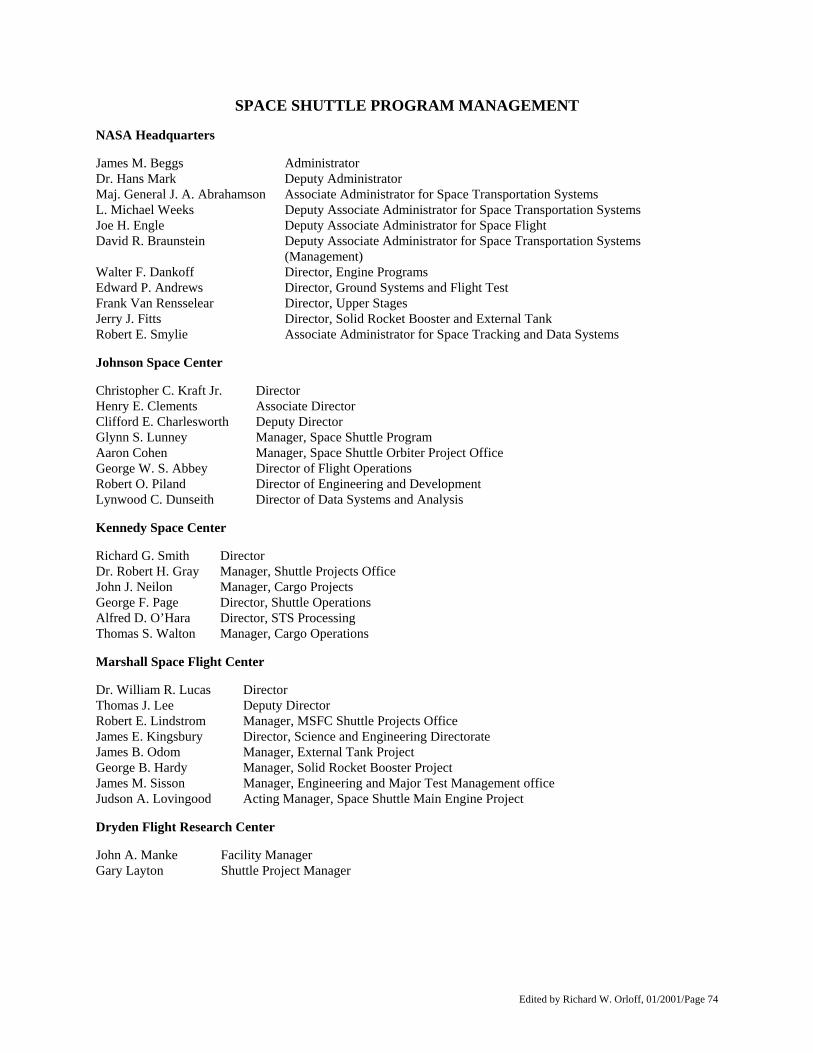
Edited by Richard W. Orloff, 01/2001/Page 74
SPACE SHUTTLE PROGRAM MANAGEMENT NASA Headquarters James M. Beggs Administrator Dr. Hans Mark Deputy Administrator Maj. General J. A. Abrahamson Associate Administrator for Space Transportation Systems L. Michael Weeks Deputy Associate Administrator for Space Transportation Systems Joe H. Engle Deputy Associate Administrator for Space Flight David R. Braunstein Deputy Associate Administrator for Space Transportation Systems
(Management) Walter F. Dankoff Director, Engine Programs Edward P. Andrews Director, Ground Systems and Flight Test Frank Van Rensselear Director, Upper Stages Jerry J. Fitts Director, Solid Rocket Booster and External Tank Robert E. Smylie Associate Administrator for Space Tracking and Data Systems Johnson Space Center Christopher C. Kraft Jr. Director Henry E. Clements Associate Director Clifford E. Charlesworth Deputy Director Glynn S. Lunney Manager, Space Shuttle Program Aaron Cohen Manager, Space Shuttle Orbiter Project Office George W. S. Abbey Director of Flight Operations Robert O. Piland Director of Engineering and Development Lynwood C. Dunseith Director of Data Systems and Analysis Kennedy Space Center Richard G. Smith Director Dr. Robert H. Gray Manager, Shuttle Projects Office John J. Neilon Manager, Cargo Projects George F. Page Director, Shuttle Operations Alfred D. O’Hara Director, STS Processing Thomas S. Walton Manager, Cargo Operations Marshall Space Flight Center Dr. William R. Lucas Director Thomas J. Lee Deputy Director Robert E. Lindstrom Manager, MSFC Shuttle Projects Office James E. Kingsbury Director, Science and Engineering Directorate James B. Odom Manager, External Tank Project George B. Hardy Manager, Solid Rocket Booster Project James M. Sisson Manager, Engineering and Major Test Management office Judson A. Lovingood Acting Manager, Space Shuttle Main Engine Project Dryden Flight Research Center John A. Manke Facility Manager Gary Layton Shuttle Project Manager

Edited by Richard W. Orloff, 01/2001/Page 75
Goddard Space Flight Center Dr. Noel Hinners Director Richard S. Sade Director of Networks Directorate Space Tracking and Data Network Walter LaFleur Deputy Director of Networks Directorate (STDN) William B. Dickinson Division Chief, NASA Communications Network Donald D. Wilson Chief, NASA Communications Network Daniel Spintman Chief, Network Operations Division James M. Stevens Shuttle Network Support Manager
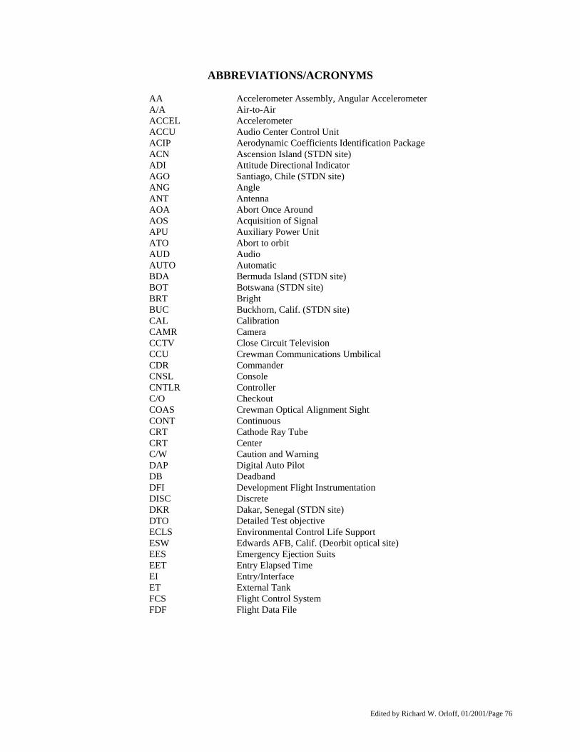
Edited by Richard W. Orloff, 01/2001/Page 76
ABBREVIATIONS/ACRONYMS
AA Accelerometer Assembly, Angular Accelerometer A/A Air-to-Air ACCEL Accelerometer ACCU Audio Center Control Unit ACIP Aerodynamic Coefficients Identification Package ACN Ascension Island (STDN site) ADI Attitude Directional Indicator AGO Santiago, Chile (STDN site) ANG Angle ANT Antenna AOA Abort Once Around AOS Acquisition of Signal APU Auxiliary Power Unit ATO Abort to orbit AUD Audio AUTO Automatic BDA Bermuda Island (STDN site) BOT Botswana (STDN site) BRT Bright BUC Buckhorn, Calif. (STDN site) CAL Calibration CAMR Camera CCTV Close Circuit Television CCU Crewman Communications Umbilical CDR Commander CNSL Console CNTLR Controller C/O Checkout COAS Crewman Optical Alignment Sight CONT Continuous CRT Cathode Ray Tube CRT Center C/W Caution and Warning DAP Digital Auto Pilot DB Deadband DFI Development Flight Instrumentation DISC Discrete DKR Dakar, Senegal (STDN site) DTO Detailed Test objective ECLS Environmental Control Life Support ESW Edwards AFB, Calif. (Deorbit optical site) EES Emergency Ejection Suits EET Entry Elapsed Time EI Entry/Interface ET External Tank FCS Flight Control System FDF Flight Data File
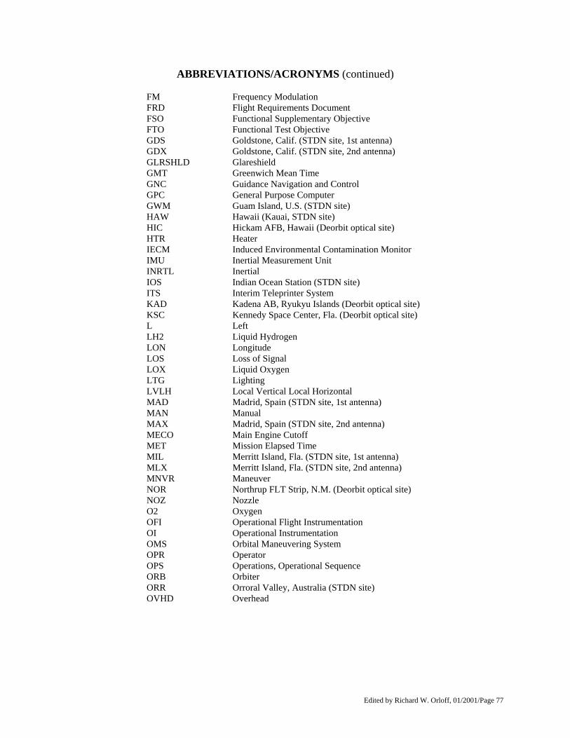
Edited by Richard W. Orloff, 01/2001/Page 77
ABBREVIATIONS/ACRONYMS (continued)
FM Frequency Modulation FRD Flight Requirements Document FSO Functional Supplementary Objective FTO Functional Test Objective GDS Goldstone, Calif. (STDN site, 1st antenna) GDX Goldstone, Calif. (STDN site, 2nd antenna) GLRSHLD Glareshield GMT Greenwich Mean Time GNC Guidance Navigation and Control GPC General Purpose Computer GWM Guam Island, U.S. (STDN site) HAW Hawaii (Kauai, STDN site) HIC Hickam AFB, Hawaii (Deorbit optical site) HTR Heater IECM Induced Environmental Contamination Monitor IMU Inertial Measurement Unit INRTL Inertial IOS Indian Ocean Station (STDN site) ITS Interim Teleprinter System KAD Kadena AB, Ryukyu Islands (Deorbit optical site) KSC Kennedy Space Center, Fla. (Deorbit optical site) L Left LH2 Liquid Hydrogen LON Longitude LOS Loss of Signal LOX Liquid Oxygen LTG Lighting LVLH Local Vertical Local Horizontal MAD Madrid, Spain (STDN site, 1st antenna) MAN Manual MAX Madrid, Spain (STDN site, 2nd antenna) MECO Main Engine Cutoff MET Mission Elapsed Time MIL Merritt Island, Fla. (STDN site, 1st antenna) MLX Merritt Island, Fla. (STDN site, 2nd antenna) MNVR Maneuver NOR Northrup FLT Strip, N.M. (Deorbit optical site) NOZ Nozzle O2 Oxygen OFI Operational Flight Instrumentation OI Operational Instrumentation OMS Orbital Maneuvering System OPR Operator OPS Operations, Operational Sequence ORB Orbiter ORR Orroral Valley, Australia (STDN site) OVHD Overhead
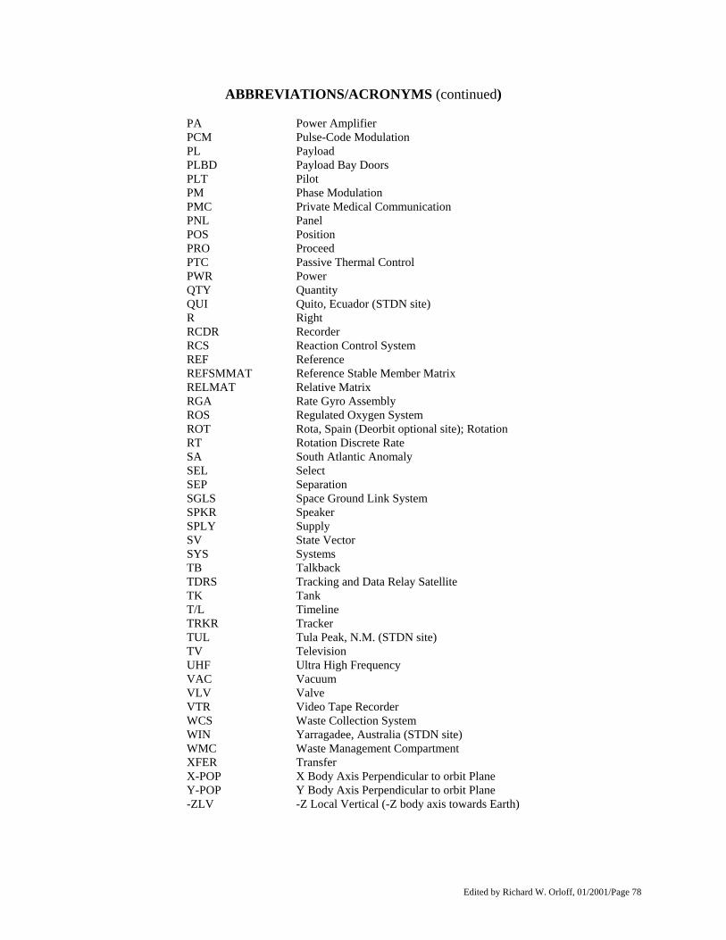
Edited by Richard W. Orloff, 01/2001/Page 78
ABBREVIATIONS/ACRONYMS (continued)
PA Power Amplifier PCM Pulse-Code Modulation PL Payload PLBD Payload Bay Doors PLT Pilot PM Phase Modulation PMC Private Medical Communication PNL Panel POS Position PRO Proceed PTC Passive Thermal Control PWR Power QTY Quantity QUI Quito, Ecuador (STDN site) R Right RCDR Recorder RCS Reaction Control System REF Reference REFSMMAT Reference Stable Member Matrix RELMAT Relative Matrix RGA Rate Gyro Assembly ROS Regulated Oxygen System ROT Rota, Spain (Deorbit optional site); Rotation RT Rotation Discrete Rate SA South Atlantic Anomaly SEL Select SEP Separation SGLS Space Ground Link System SPKR Speaker SPLY Supply SV State Vector SYS Systems TB Talkback TDRS Tracking and Data Relay Satellite TK Tank T/L Timeline TRKR Tracker TUL Tula Peak, N.M. (STDN site) TV Television UHF Ultra High Frequency VAC Vacuum VLV Valve VTR Video Tape Recorder WCS Waste Collection System WIN Yarragadee, Australia (STDN site) WMC Waste Management Compartment XFER Transfer X-POP X Body Axis Perpendicular to orbit Plane Y-POP Y Body Axis Perpendicular to orbit Plane -ZLV -Z Local Vertical (-Z body axis towards Earth)
Edited by Richard W. Orloff, 01/2001/Page 79
SHUTTLE FLIGHTS AS OF JUNE 1982 3 TOTAL FLIGHTS OF THE SHUTTLE SYSTEM
STS-3 03/22/82 – 02/30/82
STS-2 11/12/81 – 11/14/81
STS-1 04/12/81 - 04/14/81
OV-102
Columbia (3 flights)