Original operating instructions IRwin S/SX/SXT/SXG/SXGT
136
Original operating instructions IRwin ® S/SX/SXT/SXG/SXGT Portable Methane Leak Detector mina66en1-18-(2101) Catalog No. 580-000, 580-010, 580-015, 580-020, 580-030 From software version 4.01.01
Transcript of Original operating instructions IRwin S/SX/SXT/SXG/SXGT

Original operating instructions
IRwin® S/SX/SXT/SXG/SXGTPortable Methane Leak Detector
mina66en1-18-(2101)
Catalog No.580-000, 580-010, 580-015, 580-020, 580-030
From software version4.01.01

INFICON GmbH
Bonner Strasse 498
50968 Cologne, Germany

INFICON Table of Contents
IRwin®-Operating-instructions-mina66en1-18-(2101) iii
Table of Contents1 About these instructions ................................................................................................................................... 7
1.1 Target groups ........................................................................................................................................... 7
1.2 Warnings................................................................................................................................................... 7
2 Safety ............................................................................................................................................................... 8
2.1 Intended use ............................................................................................................................................. 8
2.2 Special conditions for safe use ................................................................................................................. 9
2.2.1 Intrinsic Safety (Ex protection) ...................................................................................................... 9
2.2.2 Certified Gas Measurement ........................................................................................................ 10
2.3 Owner/supervisor responsibilities ........................................................................................................... 11
2.4 Duties of the operator ............................................................................................................................. 12
2.5 Safe operation ........................................................................................................................................ 12
3 Scope of delivery ............................................................................................................................................ 13
4 Description...................................................................................................................................................... 14
4.1 Function .................................................................................................................................................. 14
4.2 Design of the leak detector ..................................................................................................................... 15
4.3 Probes .................................................................................................................................................... 16
4.4 Display .................................................................................................................................................... 19
4.5 Technical data ........................................................................................................................................ 22
4.5.1 EX certification (intrinsic safety).................................................................................................. 24
4.5.2 Sensors....................................................................................................................................... 24
4.6 Factory settings ...................................................................................................................................... 32
4.7 Concentration of calibration and test gases............................................................................................ 34
5 Getting started ................................................................................................................................................ 36
5.1 Charging the battery ............................................................................................................................... 36
5.2 Assembling the probe system................................................................................................................. 39
6 Operation........................................................................................................................................................ 42
6.1 Switch ON............................................................................................................................................... 42
6.2 Startup Settings ...................................................................................................................................... 43
6.2.1 Select available operating modes ............................................................................................... 44
6.2.2 Adjust the local time.................................................................................................................... 44
6.2.3 Setting the language ................................................................................................................... 44
6.2.4 Activating Audio Locating Signal................................................................................................. 44

Table of Contents INFICON
iv IRwin®-Operating-instructions-mina66en1-18-(2101)
6.2.5 Disabling audio alarms in non-Ex modes.................................................................................... 45
6.2.6 Bluetooth Pairing Code required................................................................................................. 45
6.2.7 Change permission level............................................................................................................. 45
6.2.8 PPM Adjustment Factor .............................................................................................................. 46
6.2.9 Select Gas (Ex)........................................................................................................................... 46
6.2.10 100% CH4 LEL conc................................................................................................................... 46
6.2.11 Set limits and alarm levels .......................................................................................................... 46
6.2.12 Universal Mode ........................................................................................................................... 48
6.2.13 Universal Cal Setup / AbG Cal Setup ......................................................................................... 49
6.2.14 Universal Fnc Test conc / AbG Fnc Test conc............................................................................ 49
6.2.15 Set the brightness of the display................................................................................................. 49
6.2.16 Screensaver timeout ................................................................................................................... 49
6.2.17 Auto-Rotate Screen .................................................................................................................... 50
6.2.18 Configure data logging................................................................................................................ 50
6.2.19 Enable dead band suppression (IRwin SXnn only)..................................................................... 50
6.2.20 Setting the Function Test Interval ............................................................................................... 51
6.2.21 Transfer data to computer........................................................................................................... 51
6.2.21.1 Install software for data transfer......................................................................................... 51
6.2.21.2 Pairing the leak detector with computer via Bluetooth interface ........................................ 52
6.2.21.3 Transfer log files from leak detector to computer............................................................... 52
6.2.21.4 Real-time streaming from leak detector to computer ......................................................... 53
6.3 Operating modes .................................................................................................................................... 54
6.3.1 Select operating mode ................................................................................................................ 54
6.3.2 Operating mode “Above Ground”................................................................................................ 54
6.3.3 Operating mode "Universal"........................................................................................................ 56
6.3.4 Operating mode “Bar Hole”......................................................................................................... 58
6.3.4.1 Automatic “Bar Hole” testing .............................................................................................. 59
6.3.4.2 Setting parameters for “Auto Bar Hole”.............................................................................. 60
6.3.5 Operating mode "GC Ethane Analysis" ...................................................................................... 61
6.3.6 Operating mode “Plants”............................................................................................................. 65
6.3.7 Operating mode "House" ............................................................................................................ 67
6.3.8 Operating mode "Gas Purity” ...................................................................................................... 68
6.3.9 Operating mode "Ex" .................................................................................................................. 70
6.3.10 Operating mode "Ex Tox” ........................................................................................................... 73
6.3.10.1 Change gas type for %LEL measurement ......................................................................... 76

INFICON Table of Contents
IRwin®-Operating-instructions-mina66en1-18-(2101) v
6.3.11 IR Ethane Analysis and compensation ....................................................................................... 77
6.3.11.1 Entering ethane concentration manually............................................................................ 78
6.3.11.2 Setting reminder for IR Ethane Analysis ............................................................................ 78
6.3.11.3 Performing IR Ethane Analysis after automatic reminder .................................................. 79
6.3.11.4 Starting IR Ethane Analysis manually ................................................................................ 80
6.3.11.5 Viewing IR Ethane Analysis info ........................................................................................ 80
6.3.12 Calibration (adjustment).............................................................................................................. 81
6.3.12.1 Standard calibration procedures ........................................................................................ 84
6.3.12.2 Setting of calibration gas concentrations ........................................................................... 85
6.3.12.3 Adjust calibration reminder................................................................................................. 86
6.4 Performing function tests ........................................................................................................................ 87
6.5 Measuring ............................................................................................................................................... 89
6.6 Perform self test...................................................................................................................................... 89
6.7 Viewing Status menu.............................................................................................................................. 89
6.8 Logging data to file ................................................................................................................................. 90
6.9 Information.............................................................................................................................................. 90
6.9.1 Retrieve information and statistics .............................................................................................. 90
6.9.2 Warnings and error messages.................................................................................................... 90
6.9.3 Viewing the Service Screen ........................................................................................................ 94
6.10 Switching OFF ........................................................................................................................................ 94
7 Maintenance ................................................................................................................................................... 96
7.1 Maintenance plan ................................................................................................................................... 96
7.2 Spare parts list........................................................................................................................................ 96
7.3 General check of probe system.............................................................................................................. 97
7.4 Maintenance of the leak detector............................................................................................................ 98
7.4.1 Seasonal shut-down ................................................................................................................... 98
7.4.2 Change the cigarette filter in the sample inlet............................................................................. 98
7.5 Maintenance of the hand probe.............................................................................................................. 99
7.6 Maintenance of the carpet probe ............................................................................................................ 99
7.7 Maintenance of the bell probe .............................................................................................................. 100
7.8 Maintenance of the swan neck ............................................................................................................. 101
7.9 Maintenance of the bar hole probe....................................................................................................... 101
8 Decommissioning the leak detector.............................................................................................................. 102
8.1 Sending in the leak detector ................................................................................................................. 102
8.2 Disposing of the equipment .................................................................................................................. 104

Table of Contents INFICON
vi IRwin®-Operating-instructions-mina66en1-18-(2101)
8.3 Safe battery removal............................................................................................................................. 104
9 Certificates.................................................................................................................................................... 106
9.1 TÜV, Certificate for lower explosive limit (LEL) .................................................................................... 107
9.2 Certificate for oxygen and toxic gases.................................................................................................. 111
9.3 Certificate for software for Ex/ExTox .................................................................................................... 113
9.4 CE Declaration of Conformity ............................................................................................................... 114
9.5 EU Konformitätserklärung IRwin S (DE)............................................................................................... 119
9.6 IRwin ATEX certificate Issue 2 ............................................................................................................. 121
9.7 IRwin CSA certificate Issued August 2019 ........................................................................................... 124
9.8 IRwin IECEx certificate issue 1............................................................................................................. 126
9.9 IRwin NEPSI certificate 2019................................................................................................................ 130
Index............................................................................................................................................................. 132

INFICON About these instructions | 1
IRwin®-Operating-instructions-mina66en1-18-(2101) 7 / 136
1 About these instructionsThis document applies to the software version stated on the title page.
Product names may occur in the document, which are added for identificationpurposes only and belong to the respective owner of the rights.
1.1 Target groupsThese Operating Instructions are written for trained and experienced gas pipelinesurvey operators.
1.2 Warnings
DANGER
Imminent hazard resulting in death or serious injuries
WARNING
Hazardous situation resulting in potential death or serious injuries
CAUTION
Hazardous situation resulting in minor injuries
NOTICE
Hazardous situation resulting in damage to property or the environment

2 | Safety INFICON
8 / 136 IRwin®-Operating-instructions-mina66en1-18-(2101)
2 Safety
2.1 Intended useIRwin Methane Leak Detector is intended for professional use in residential andcommercial areas. The operation of the equipment requires sufficient knowledge andexperience in gas pipeline inspection. The different IRwin versions are equipped forthe measurement of different gases, see "Technical data [} 22]", as well as for theapplications listed below:
• IRwin S
Universal leak survey and pin-pointing in non-hazardous/not Ex classified areas. DVGW modes: Above Ground, Bar hole
• IRwin SX (EX certified)
LEL measurement, Universal leak survey and pin-pointing in hazardous Exclassified areas. DVGW modes: Above Ground, Bar hole, Plant, House, Gas Purity, Ex
• IRwin SXT (EX certified)
LEL measurement, Toxic gas alarm, Universal leak survey and pin-pointing inhazardous Ex classified areas.DVGW modes: Above Ground, Bar hole, Plant, House, Gas Purity, Ex, Ex Tox
• IRwin SXG (EX certified)
LEL measurement, GC gas source analysis, Universal leak survey and pin-pointing in hazardous Ex classified areas. DVGW modes: Above Ground, Bar hole, Plant, House, Gas Purity, GC Ethane Analysis
• IRwin SXGT (EX certified)
LEL measurement, GC gas source analysis, Toxic gas alarm, Universal leaksurvey and pin-pointing in hazardous Ex classified areas. DVGW modes: Above Ground, Bar hole, Plant, House, Gas Purity, GC Ethane
IRwin SX, IRwin SXG, IRwin SXT, IRwin SXGT and the included original INFICONhand probe are intrinsically safe and can be used in areas with potentially explosiveatmospheres according to the EX rating and EX application it is certified for (see "EXcertification (intrinsic safety) [} 24]").
These models are jointly referred to as IRwin SXnn in the following.
IRwin S and accessories other than the included, original INFICON hand probe arenot EX certified.
Pay attention to the safety instructions "Safe operation [} 12]".

INFICON Safety | 2
IRwin®-Operating-instructions-mina66en1-18-(2101) 9 / 136
• You must assemble, operate and maintain the equipment only in compliance withthese operating instructions.
• Use only within the allowed ambient conditions. Operating or storing theequipment outside the given range can result in erroneous readings and possiblemalfunction.
• Use the leak detector exclusively for the detection of the specified gases.
Improper use • Do not suck liquids into the leak detector.
• Do not suck dirt or sand into the leak detector.
• Do not use IRwin S in areas with potentially explosive atmospheres.
See also
2 Technical data [} 22]
2 EX certification (intrinsic safety) [} 24]
2.2 Special conditions for safe use
2.2.1 Intrinsic Safety (Ex protection)IRwin is certified intrinsically safe to prevent ignition of flammable atmospheres.
IRwin holds an ATEX certificate for EU and corresponding certificates for several otherregions as shown by the attached certificates, see Certificates [} 106]).
For details of rating, see EX certification (intrinsic safety) [} 24].
The "X" after the respective type certificate number relates to the following specialconditions for safe use:
The only device allowed to be connected to the charging socket on any of the models
• IRwin SX
• IRwin SXT
• IRwin SXG
• IRwin SXGT
is the Ex Certified IRwin Charging adapter (PN 580-604).
The charger or car adapter is subsequently connected to the inlet of the Ex CertifiedIRwin Charging Adapter.
This means that the charger for IRwin S must, under no circumstances, be connecteddirectly to the charging socket on any of IRwin models SX, SXT, SXG, and SXGT. Seealso Charging the battery [} 36].
IRwin SXnn is certified as intrinsically safe at an ambient temperature of -20 - +50°C.Further temperature restrictions apply to oxygen and toxic gas measurment of IRwinSXT and SXGT. See Certified Gas Measurement.

2 | Safety INFICON
10 / 136 IRwin®-Operating-instructions-mina66en1-18-(2101)
IRwin SXnn is certified for use in Gas groups IIA, IIB and IIC and in Zones 0, 1 and 2.The external surface of the enclosure is therefore slightly conductive to preventelectrostatic charging and sparks. Labels, ink or paint added for marking purposesmust not be larger than 400 mm2. Adding larger labels invalidates the Ex certificationsdue to risk for electrostatic charging and discharging.
2.2.2 Certified Gas MeasurementIRwin SX, IRwin SXG, IRwin SXT, and IRwin SXGT are certified by TÜV Rheinland toEN 60079-29-1 for measuring methane (CH4), propane C3H8, butane C4H10 and naturalgas concentration in units of percentage of lower flammability level. In IRwin we usethe more widely known acronym LEL as synonymous with the more correct LFL.
IRwin SXT and IRwin SXGT are, in addition, also certified by TÜV Rheinland toEN50104 and EN 45544 for measuring Oxygen (O2), Carbon Dioxide (CO2), CarbonMonoxide (CO) and Hydrogen Sulfide (H2S).
The certification is valid in an ambient temperature of -15 to +40 °C and subject toperiodic calibration checks (called function test in this manual) and if requiredcalibration adjustments (called Calibration in this manual), see "Setting the FunctionTest Interval [} 51]" and ”Calibration (adjustment) [} 81]”.
IRwin S, IRwin SX and IRwin SXG are operable within -20 to +50 °C. The certificationis valid in an ambient temperature of -15 to +40 °C. The accuracy may not beaccording to specification outside this range.
IRwin SXT and IRwin SXGT are operable within -20 to +40 °C. The certification isvalid in an ambient temperature of -15 to +40 °C.

INFICON Safety | 2
IRwin®-Operating-instructions-mina66en1-18-(2101) 11 / 136
2.3 Owner/supervisor responsibilitiesThe following notes are for organizations or any person responsible for the safe andeffective use of this equipment.
Safety consciousoperation
• Check that the leak detector is properly calibrated and not damaged before usingit.
• Make sure you operate the leak detector in accordance with this manual.
• Adhere to the following regulations:
– Intended use
– General applicable safety and accident prevention regulations
– International, national and local standards and guidelines
– Additional equipment-related provisions and regulations
• Use only original parts or parts approved by the manufacturer.
• Keep this instruction manual available on site.
• It is recommended that EN/IEC 60079-29-2 is observed to guarantee proper useand continued proper function of IRwin when used in Ex or ExTox modes.
It is also recommended that IRwin is submitted for yearly service at an approvedservice site.
Contact your supplier for contact details.
EN/IEC 60079-29-2: (Explosive atmospheres – Gas detectors – Selection, installation,use and maintenance of detectors for flammable gases and oxygen)
Staff qualifications • Only properly trained staff should be permitted to work with and on the equipment.The training must cover the actual equipment model used.
• Make sure that users have read and understood the operating instructions and allother applicable documents.
Non-authorized repairsforbidden
The manufacturer (INFICON) denies all responsibility for the compliance of thisproduct with any of the type certificates for this product if any repairs or serviceinvolving opening the instrument enclosure (yellow box) has been performed byindividuals or organizations not qualified therefore in writing by INFICON AB, Sweden.The manufacturer (INFICON) denies all responsibility for the compliance of thisproduct with any of the type certificates for this product if the equipment is used in anyway not conforming to the instructions in this User Manual. Replacement of externallyaccessible parts such as probes and filters is allowed with the exception of the HandProbe and the hose between Hand Probe and IRwin detector. These two parts arecertified anti-static and must not be replaced with non-original parts.

2 | Safety INFICON
12 / 136 IRwin®-Operating-instructions-mina66en1-18-(2101)
2.4 Duties of the operator• Read, observe, and follow the information in this manual and in the work
instructions provided by the owner. This concerns in particular the safetyinstructions and warnings.
• Always observe the complete operating instructions for all work.
• If you have any questions about operation or maintenance that are not answeredin this manual, please contact Customer Service.
2.5 Safe operationHazards due tochemical substancesand explosive gases
• Do not expose the leak detector to excess heat or a naked flame.
• Agressive substances such as solvents and other chemicals can damage theequipment.
• Adhere to the restrictions of use.
• Do not suck liquids into the leak detector. Proper maintenance of all filters reducesthis risk.
Operation mode andEx
The safety related modes Ex and Ex Tox has certified safety features. The detectormonitors its functionality and proper function is indicated by an acoustic alive signalbeeping every 20 s and by the LED being green. This requires that the accuracy ofleak detector is verified by function test (and calibrating when required) according tothe instructions and intervals stated in this manual.If the signal LED is red, this indicates an alarm or an error.
Green LED and short beep every 20 s: Function OK.
Red LED: Gas alarm or instrument error.
Yellow LED: Special state Special state indicates functioning system but alarms aretypically not active. This special state may occur for example during calibration orwhen changing a setting in the leak detector.
IRwin Methane Leak Detector was built according to the state-of-the-art and therecognized safety regulations. Nevertheless, improper use may result in risk to life andlimb on the part of the user or third parties, or damage to the leak detector or otherproperty may occur.

INFICON Scope of delivery | 3
IRwin®-Operating-instructions-mina66en1-18-(2101) 13 / 136
3 Scope of deliveryThe following is included in the delivery of IRwin:
Article (part number) Quantity
Hand Probe (580-100) 1
Harness (580-405) 1
USB memory with Operating instructions in severallanguages
1
Charger cable for car (591-361) 1
Charger for IRwin (all models) 1
Certified IRwin Charging Adapter (580-604) 1
Poduction and calibration certificates 1
Operation instructions (english) 1
Check that the delivery is complete.
IRwin Accessory Kit (580-712):
Article (part number) Quantity
Rod 850mm (580-150) 1
Extension Rod 150mm (580-160) 1
Carpet (580-211) 1
Bell (580-301) 1
Carrying Case IRwin (580-450) 1
Filter-kit (580-700) 1
Bar Hole Probe (580-115) 1
Extension Connector (580-220) 1
IRwin Compact Kit (580-250):
Article (part number) Quantity
Compact Rod (580-170) 1
Extension Rod 150mm (580-160) 1
OFDR, on Demand Flow Regulator (580-230) 1
Bell (580-301) 1
Protector Bell Assembly (581-932) 2
Filter-kit 580-700 1
O-ring kit 10-pack 6x2 mm (581-311) 1
TX20 Torx key (581-313) 1
Spanner 19 mm / 3/4" (581-310) 2
Instructions 1

4 | Description INFICON
14 / 136 IRwin®-Operating-instructions-mina66en1-18-(2101)
4 Description
4.1 FunctionIRwin is a portable methane leak detector for survey, leak pinpointing, maintenanceand commissioning checks of any utility gas or landfill installation or pipeline. Itmeasures following gases depending on the leak detector version:
• Methane
• Carbon dioxide
• Ethane
• Propane
• Butane
• Oxygen
• Hydrogen sulfide
• Carbon monoxide
There are several probes available for the leak detector:
• Carpet probe is used for surveying paved or smooth surfaces. Pull or push thecarpet along the surface.
• Use bell probe for measuring gas at specific points. Press the bell firmly down topull gas through the surface.
• Hand probe is used for checking features on or in buildings. Hand probe alsoconstitutes the handle for carpet probe and bell probe.
• Bar Hole probe is used to sample air from drilled holes. Push into hole and tightenscrew to expand rubber before connecting sample line.
• Optional Hand Probe Flexible Extension can be connected to the hand probe orrod for easier access.
• Swan Neck Probe is used on uneven surfaces and in bushes etc.
• Flexi Bell is used for simple survey including meters and piping. The bell adapts topipe geometry.
INFICON single-cellwide range technology(patent pending)
IRwin methane leak detector uses the unique INFICON single-cell wide rangetechnology for detecting all concentrations from 1 ppm to 100 Vol% methane. Thistechnology is very sensitive to the ethane content of natural gas. Therefore, largedeviations can occur at higher methane concentrations if the ethane concentration isnot compensated for. The instrument has built-in routines for ethane compensation.The actual ethane concentration can be determined using the IR Ethane Analysisfunction. This can be used to automatically set the compensation concentration. If

INFICON Description | 4
IRwin®-Operating-instructions-mina66en1-18-(2101) 15 / 136
preferred you can instead set the ethane content manually. The safety certified modesEx and Ex Tox are not affected by this phenomenon. See "IR Ethane Analysis andcompensation [} 77]".
IRwin SXG and SXGT models also have GC Ethane Analysis capability fordistinguishing between Natural gas (NG), liquid petroleum gas (LPG) and swamp gasby determining the presence of methane, ethane and propane in the sampled gas.
The GC Ethane Analysis function is not affecting the ethane compensation.
4.2 Design of the leak detector
1 2
3
4
5
Fig. 1: Design of the Leak Detector
1 Reference inlet 4 Gas outlet
2 Display 5 Charging socket
3 Gas inlet

4 | Description INFICON
16 / 136 IRwin®-Operating-instructions-mina66en1-18-(2101)
4.3 Probes
WARNING
Risk of explosion due to not approved probe parts.
The original INFICON Hand probe is the only part of the probe system that is certifiedfor use in potentially explosive areas. Other parts of the probe system are not allowedin classified hazardous areas (Zone 0, 1, 2, Div 1 or 2).
► Pay proper attention to safety when using other accessories for locating andpinpointing gas leaks in none classified areas.
Carpet probe When you are looking for gas leaks on paved surfaces, use the INFICON Carpetprobe. Pull or push the INFICON Carpet probe along the surface.
Fig. 2: Carpet probe
Bell probe When searching for or measuring gas leaks at particular spots, use the INFICON Bellprobe. This can be used to pull gas through most pavings. It is also suitable foremergency testing if surface is wet.
Fig. 3: Bell probe

INFICON Description | 4
IRwin®-Operating-instructions-mina66en1-18-(2101) 17 / 136
Hand probe You can use the INFICON Hand probe to search for gas in building installations. Thehand probe also constitutes the handle for the INFICON Carpet probe and for theINFICON Bell probe.
Fig. 4: Hand probe
Bar Hole Probe The INFICON Bar Hole Probe is used to pump out and take samples from holes drilledin the asphalt or concrete when pin-pointing a leak. Note that the INFICON Bell Probecan be used first to reduce the number of holes.
Fig. 5: Bar Hole Probe
Hand probe The INFICON Flexible extension is practical when locating leaks in hard to reachinstallations. Use the INFICON Extension Connector to attach it to the long rod toreach even further.
Fig. 6: Hand Probe Flexible Extension

4 | Description INFICON
18 / 136 IRwin®-Operating-instructions-mina66en1-18-(2101)
Swan Neck The INFICON Swan Neck is used on uneven surfaces where the carpet probe isunpractical. Can also be practical in bushes and other “confined” areas.
Fig. 7: Swan Neck
Flexi Bell The INFICON Flexi Bell is practical for surveys including frequent entries into gardensand check of meters and piping. The softer bell adapts to pipe geometry.
Fig. 8: Flexi Bell

INFICON Description | 4
IRwin®-Operating-instructions-mina66en1-18-(2101) 19 / 136
4.4 Display
7
5
1 23
4
6
1 1
1 2
34
8
9
Above ground
5
(10 PPM)1010
Fig. 9: Display IRwin
1 Navigation buttons 2 Navigation and on / off button
3 Battery status indicator 4 Mode icon
5 Measured value, target gas andunit
6 Measurement range (in % or PPMCH4 depending on the operationmode)
7 Status indicator LED 8 Operation mode and menu bar
9 Buzzer 10 PPM threshold in Universal, AboveGround and Plants modes.
Navigation buttons Menu Upper left
Settings Upper left after pressing “Menu”
Operation Upper right
Information Lower left after pressing “Menu”
Diagnosis At lower right after pressing “Menu”
Table 1: Navigation buttons
To select a menu, press the navigation button to go to desired tab or field.
Press check mark button , select or open a highlighted option.

4 | Description INFICON
20 / 136 IRwin®-Operating-instructions-mina66en1-18-(2101)
Function buttons OK/Select/Confirm
Navigation buttons (in this case go right)
Cancel process
Start process
Start data logging
Stop data logging
Mute the alarm
Table 2: Function buttons
Symbols of the statusbar
Bluetooth activated
Symbol ON = GPS connected andtracking
Symbol flashing = GPS not connected
Battery status indicator
The color of the battery status indicator shows the remaining runtime beforeshutdown:
White: > 1h remaining
Orange: < 1h remaining
Red flashing: < 10 min remaining
Progress bars for calibration processes etc.
White bar: Process has not yet started
Light green bar: Process running
Dark green bar: Process completed
Red bar: Process failed
Table 3: Status indicators
Mode icons • Operation mode- Above Ground
• Operation mode- Bar hole
• Operation mode- Plants
• Operation mode- House
• Operation mode- Gas Purity
• Operation mode- Ex
• Operation mode- Ex Tox
• Operating mode- GC Ethane Analysis
• Operating mode- Universal
INFICON Description | 4
IRwin®-Operating-instructions-mina66en1-18-(2101) 21 / 136
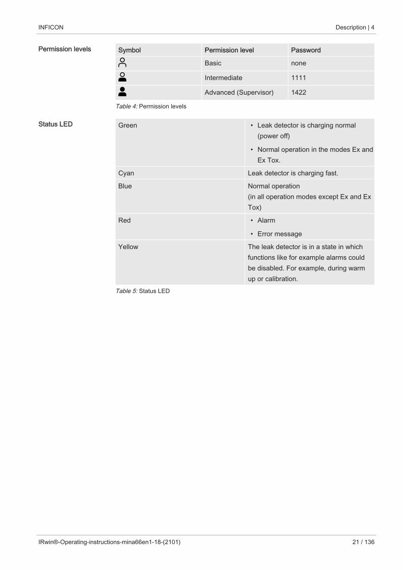
Permission levels Symbol Permission level Password
Basic none
Intermediate 1111
Advanced (Supervisor) 1422
Table 4: Permission levels
Status LED Green • Leak detector is charging normal(power off)
• Normal operation in the modes Ex andEx Tox.
Cyan Leak detector is charging fast.
Blue Normal operation (in all operation modes except Ex and ExTox)
Red • Alarm
• Error message
Yellow The leak detector is in a state in whichfunctions like for example alarms couldbe disabled. For example, during warmup or calibration.
Table 5: Status LED

4 | Description INFICON
22 / 136 IRwin®-Operating-instructions-mina66en1-18-(2101)
4.5 Technical data
Mechanical data
580-000 580-010 580-015 580-020 580-030
Name IRwin S IRwin SX IRwin SXT IRwin SXG IRwin SXGT
Weight 1.4 kg (3 lb.) 1.6 kg (3.5 lb.) 1.6 kg (3.5 lb.) 1.6 kg (3.5 lb.) 1.6 kg (3.5 lb.)
Dimensions(lxwxh)
197 x 256 x 62mm (6.6 x 9.7 x2.3 in.)
197 x 256 x 62mm (6.6 x 9.7 x2.3 in.)
197 x 256 x 62mm (6.6 x 9.7 x2.3 in.)
197 x 256 x 62mm (6.6 x 9.7 x2.3 in.)
197 x 256 x 62mm (6.6 x 9.7 x2.3 in.)
Table 6: Mechanical data
Electrical data
580-000 580-010 580-015 580-020 580-030
Name IRwin S IRwin SX IRwin SXT IRwin SXG IRwin SXGT
Power input 4 A 4 A 4 A 4 A 4 A
Memorycapacity formeasured data
64 MB 64 MB 64 MB 64 MB 64 MB
Type ofprotection
IP54 IP54 IP54 IP54 IP54
Electronicinterfaces
Bluetooth 3.0Class 1
Bluetooth 3.0Class 1
Bluetooth 3.0Class 1
Bluetooth 3.0Class 1
Bluetooth 3.0Class 1
Batteryoperating time
8 h as verifiedduringcertification,typical value 9 h
8 h as verifiedduringcertification,typical value 9 h
8 h as verifiedduringcertification,typical value 9 h
8 h as verifiedduringcertification,typical value 9 h
8 h as verifiedduringcertification,typical value 9 h
Battery chargingtime
4 h from emptyto full charge (3h for fastcharging). 4hours operationby 1 hour fastloading
4 h from emptyto full charge (3h for fastcharging). 4hours operationby 1 hour fastloading
4 h from emptyto full charge (3h for fastcharging). 4hours operationby 1 hour fastloading
4 h from emptyto full charge (3h for fastcharging). 4hours operationby 1 hour fastloading
4 h from emptyto full charge (3 hfor fastcharging). 4hours operationby 1 hour fastloading
Battery Lithium-Ion,
10.0 Ah / 7.2 V /73 Wh
Lithium-Ion
10.0 Ah / 7.2 V /73 Wh
Lithium-Ion
10.0 Ah / 7.2 V /73 Wh
Lithium-Ion
10.0 Ah / 7.2 V /73 Wh
Lithium-Ion
10.0 Ah / 7.2 V /73 Wh
Table 7: Electrical data

INFICON Description | 4
IRwin®-Operating-instructions-mina66en1-18-(2101) 23 / 136
Physical data
580-000 580-010 580-015 580-020 580-030
Name IRwin S IRwin SX IRwin SXT IRwin SXG IRwin SXGT
Noise level < 70 dB (A) < 70 dB (A) < 70 dB (A) < 70 dB (A) < 70 dB (A)
Detectablegases
Methane,ethane, propane,butane, carbondioxide
Methane, carbondioxide, ethane,propane, butane
Methane, carbondioxide, ethane,propane, butane,oxygen,hydrogen sulfide,carbonmonoxide
Methane, carbondioxide, ethane,propane, butane
Methane, carbondioxide, ethane,propane, butane,oxygen,hydrogen sulfide,carbonmonoxide
Gas flow throughsniffer line
Typically 60 l/h Typically 60 l/h Typically 60 l/h Typically 60 l/h Typically 60 l/h
Table 8: Physical data
Ambient conditions
580-000 580-010 580-015 580-020 580-030
Name IRwin S IRwin SX IRwin SXT IRwin SXG IRwin SXGT
Max. altitudeabove sea level
2000 m 2000 m 2000 m 2000 m 2000 m
Permissibleambienttemperature(duringoperation)
-20° - +50°C (-4- 122°F)
-20 - 50°C (-4 -122°F)
-15 - 40°C (-5 -104°F)
-20 - 50°C (-4 -122°F)
-15 - 40°C (-5 -104°F)
Storagetemperature
-25 - +70°C (-13- 158°F)
-25 - 70°C (-13 -158°F)
-25 - 70°C (-13 -158°F)
-25 - 70°C (-13 -158°F)
-25 - 70°C (-13 -158°F)
Pressure range 80 kPa - 120kPa
80 kPa - 120kPa
80 kPa - 120kPa
80 kPa - 120kPa
80 kPa - 120kPa
Max. relativehumidity
95% (non-condensing)
95% (non-condensing)
95% (non-condensing)
95% (non-condensing)
95% (non-condensing)
Table 9: Ambient conditions

4 | Description INFICON
24 / 136 IRwin®-Operating-instructions-mina66en1-18-(2101)
4.5.1 EX certification (intrinsic safety)Type certificate Type certificates, see "Certificates [} 106]"
The products:
• IRwin SX 580-010,
• IRwin SXT 580-015,
• IRwin SXG580-020,
• IRwin SXGT580-030,
are Ex certified with rating according to the following table. IRwin S 580-000 is not Excertified.
EX rating EX rating Ex ia IIC T3, Tamb: -20°C - +50°C, II 1G (EPL Ga)
USA: Intrinsically safe, Class I, Division 1, Groups A,B, C and D.
EX ranges of applications • Zones: 0, 1 and 2
• Gas groups: IIA, IIB and IIC
• Temperature classes: T1, T2 and T3
• USA: Zone 0, Class I, Division 1, Groups A, B, Cand D.
Table 10: EX rating
4.5.2 SensorsBasic sensor data Gas (measurement range) Sensor Warm up time
CH4, C3H8, C4H10 Infrared (IR) < 30 s
CO2 Infrared (IR) < 30 s
O2, CO, H2S Electrochemical < 120 s O2 sensor: 1 - 12 hours ifstored with flat battery.
Sensor performancedata
The calibration gases defined below are the typical gases and gas mixes used tocalibrate the different modes. For optimum performance adjust these settings to theactual concentrations of the gases used. See Calibration (adjustment) [} 81].

INFICON Description | 4
IRwin®-Operating-instructions-mina66en1-18-(2101) 25 / 136
Universal mode
This mode is available if Universal Mode option is enabled. See Operating mode"Universal" [} 56].
Measurementprinciple
Infrared (IR)
Measurementrange
CH4, C3H8, C4H10: 1 ppm - 100 Vol%
The following is also displayed when total NG is above 2.7 Vol%:
C2H6 content in NG: 0.5 - 8 Vol%
CO2: 0.1 - 20 Vol%
Resolution CH4: 1 ppm (0 - 100 ppm), 10 ppm (110 - 990 ppm), 0.1 Vol%(0.1 - 2.7 Vol%), 1 Vol% (>2.7 Vol%)
CO2: 0.1 Vol% (0.1 - 1 Vol%), 1 Vol% (>1 Vol%)
C2H6: 0.1 Vol% (Auto test) 0.5 Vol% (manual selection)
Measurementerror
CH4: +5/-2 ppm (<20 ppm), ±10 % (20 - 50 ppm), ±5 % (50 ppm- 2.2 Vol%), ±20 % (2.2 - 2.7 Vol%), ±3 Vol% (>2.7 Vol%)
CO2: ±1% (<10 Vol%), ±20% (>10 Vol%)
Response time t50 <3 s (<2.7 Vol%), <5 s (>2.7 Vol%),
t90<5 s (<2.7 Vol%), <10 s (>2.7 Vol%)
Recovery time t50 <3 s (<2.7 Vol%), <5 s (>2.7 Vol%),
t10 <5 s (<2.7 Vol%), <10 s (>2.7 Vol%)
Cross sensitivity All hydrocarbons CxHy
CO2 and H2O: Negligible
Lifetime Guaranteed 1 year, expected > 2 years
Calibrationgases
Fresh air, CH4 in synthetic air: 10 ppm, 100 ppm 2.2 Vol%, 100Vol% CO2, 20 Vol%
Note: IRwin allows other concentrations and reduced number of gases. Themeasurement error may fall outside specification if choosing other set-up than therecommended.

4 | Description INFICON
26 / 136 IRwin®-Operating-instructions-mina66en1-18-(2101)
Above ground mode:
This mode is not available if Universal mode option is activated.
Measurementprinciple
Infrared (IR)
Measurementrange
CH4, C3H8, C4H10: 1 ppm - 5 Vol%
Resolution 1 ppm (0 - 100 ppm), 10 ppm (110 - 990 ppm), 0,1 Vol% (0,1 - 5Vol%)
Measurementerror
+5/-2 ppm (<20 ppm), ±10% (20 - 50 ppm), ±5% (50 ppm - 2.2Vol%), ±20% (2.2 - 5 Vol%)
Response time t50 <3 s, t90 <5 s
Recovery time t50 <3 s, t10 <5 s
Cross sensitivity All hydrocarbons CxHy
Lifetime Guaranteed 1 year, expected > 2 years
Calibrationgases
Fresh air, CH4 in synthetic air: 10 ppm, 100 ppm, 2.2 Vol%
Bar hole mode:
This mode is not available if Universal mode option is activated.
Measurementprinciple
Infrared (IR)
Measurementrange
CH4, C3H8, C4H10: 0.1 - 100 Vol%
C2H6 content in CNG: 0.5 - 8 Vol%
CO2: 0.1 - 20 Vol%
Resolution CH4 & CO2: 0.1 Vol% (0.1 - 1 Vol%), 1 Vol% (>1 Vol%)
C2H6: 0.1 Vol% (Auto test) 0.5 Vol% (manual selection)
Measurementerror
CH4: ±3 Vol%
CO2: ±1% (<10 Vol%), ±20% (>10 Vol%)
Response time t50 <5 s, t90 <10 s
Recovery time t50 <5 s, t10 <10 s
Cross sensitivity All hydrocarbons CxHy
CO2: Negligible
Lifetime Guaranteed 1 year, expected > 2 years
Calibrationgases
Fresh air, CH4 in synthetic air: 2.2 Vol%, 100 Vol%. CO2, 20 Vol%

INFICON Description | 4
IRwin®-Operating-instructions-mina66en1-18-(2101) 27 / 136
GC Ethane Analysis mode:
Measurementprinciple
Gas Chromatography separation with semiconductor detector
Measurementrange
1000 ppm gas needed in sample. This refers to totalhydrocarbon content (i.e., natural gas, swamp gas or LPG etc.).
Capability Can identify Natural Gas at 0.5% C2H6level.Automatic interpretation of result as either of:
• NG with Ethane detected
• Methane detected
• LPG detected
• Gas type not identified (given if result is not clear)
Cycle time*: Typically 3.5 min total at 25C.
Lifetime Separation column: Guaranteed 3 years, expected > 10 years
Semiconductor sensor: Guaranteed 1 year, expected 3 years.
* Times given are valid after 1 h operation in given ambient temperature. Timesinclude purge before and after anlysis. Times are longer at lower temperatures.

4 | Description INFICON
28 / 136 IRwin®-Operating-instructions-mina66en1-18-(2101)
House mode:
This mode is not available if Universal mode option is activated.
Measurementprinciple
Infrared (IR)
Measurementrange
CH4, C3H8, C4H10: 1 ppm - 100 Vol%
Resolution 1 ppm (0 - 100 ppm), 10 ppm (110 - 990 ppm), 0.1 Vol% (0.1 - 1Vol%), 1 Vol% (>5 Vol%)
Measurementerror
+5/-2 ppm (<20 ppm), ±10% (20 - 50 ppm), ±5% (50 ppm - 2.2Vol%), ±20% (2.2 - 5 Vol%)
Response time t50 <3 s, t90 <5 s
Recovery time t50 <3 s, t10 <5 s
Cross sensitivity All hydrocarbons CxHy
Lifetime Guaranteed 1 year, expected > 2 years
Calibrationgases
Fresh air, CH4 in synthetic air: 10 ppm, 100 ppm, 2.2 Vol%

INFICON Description | 4
IRwin®-Operating-instructions-mina66en1-18-(2101) 29 / 136
Plants mode:
This mode is not available if Universal mode option is activated.
Measurementprinciple
Infrared (IR)
Measurementrange
CH4, C3H8, C4H10: 1 ppm - 5 Vol%
Resolution 1 ppm (0 - 100 ppm), 10 ppm (110 - 990 ppm), 0,1 Vol% (0,1 - 5Vol%)
Measurementerror
+5/-2 ppm (<20 ppm), ±10% (20 - 50 ppm), ±5% (50 ppm - 2.2Vol%), ±20% (2.2 - 5 Vol%)
Response time t50 <3 s, t90 <5 s
Recovery time t50 <3 s, t10 <5 s
Cross sensitivity All hydrocarbons CxHy
Lifetime Guaranteed 1 year, expected > 2 years
Calibrationgases
Fresh air, CH4 in synthetic air: 10 ppm, 100 ppm, 2.2 Vol%
Gas Purity mode:
This mode is not available if Universal mode option is activated.
Measurementprinciple
Infrared (IR)
Measurementrange
CH4: 0.1 - 100 Vol%
Resolution 0.5 Vol% (0.5 - 1 Vol%), 1 Vol% (>1 Vol%)
Measurementerror
±3 Vol%
Response time t50 <5 s, t90 <10 s
Recovery time t50 <5 s, t10 <10 s
Cross sensitivity All hydrocarbons CxHy
Lifetime Guaranteed 1 year, expected > 2 years
Calibration gas Fresh air, CH4 in synthetic air: 2.2 Vol%, 100 Vol%

4 | Description INFICON
30 / 136 IRwin®-Operating-instructions-mina66en1-18-(2101)
Ex mode:
This mode is not available in IRwin S.
Measurementprinciple
Infrared (IR)
Measurementrange
CH4, C3H8, C4H10: 1 - 100% LEL
Resolution 1%LEL
Measurementerror
±5%LEL
Response time CH4: t50 = 3 s, t90 = 5 s
Recovery time t50 <3 s, t10 <5 s
Cross sensitivity All hydrocarbons CxHy
Lifetime Guaranteed 1 year, expected > 2 years
Calibration gas Fresh air, CH4 in synthetic air: 2.2 Vol%
Ex Tox mode:
This mode is only available in IRwin SXT and SXGT.
Measurementprinciple
Infrared (IR)
Measurementrange
CH4, C3H8, C4H10: 1 - 100% LEL
CO2: 0.1 - 5 Vol%
O2: 0.1 - 25 Vol%
CO: 1 - 500 ppm
H2S: 0.1 - 400 ppm
Resolution CH4, C3H8, C4H10: 1% LEL
CO2: 0.05 Vol%
O2: 0.1 Vol%
CO: 1 ppm
H2S: 0.1 ppm
Measurementerror
CH4: ±5 % LEL C3H8: ±40% of indicated value C4H10: ±50% ofindicated value
CO2: ±0.1 Vol%
O2: ±0.3 Vol%
CO: ±3 ppm
H2S: ±0.5 ppm
Response time CH4: t50 <3 s, t90 <5 s

INFICON Description | 4
IRwin®-Operating-instructions-mina66en1-18-(2101) 31 / 136
O2: t50 <16 s, t90 <40 s
CO: t50 < 15 s, t90 <30 s
CO2: t50 <12 s, t90 <36 s
H2S: t50 <18 s, t90 <66 s
Recovery time CH4: t50 <3 s, t10 <5 s
CO2: t50 <12 s, t10 <36 s
O2: t50 <16 s, t10 <39 s
CO: t50 <15 s, t10 <30 s
H2S: t50 < 18 s, t10 <66 s
Sensitivity drift CH4, C3H8, C4H10: <±5 %LEL in 1 month
CO2: <±5 Vol% in 1 month
O2: <±1 Vol% in 3 months
CO: <±4% in 12 months
H2S: <±2% in 12 months
Cross sensitivity CH4: All hydrocarbons CxHy.
O2: negligible
CO: <12% of applied H2S concentration, <8% of applied H2
concentration
H2S: <1.5% of applied CO concentration, <0.3% of applied H2
concentration
CO2: negligible
Lifetime CH4, C3H8, C4H10: Guaranteed 1 year, expected > 2 years
CO2: Guaranteed 1 year, expected > 2 years
O2: Guaranteed 4 years, expected > 5 years
CO: Guaranteed 2 years, expected > 3 years
H2S: Guaranteed 2 years, expected > 3 years
Calibration gas Fresh air, ToxMix (CH4 2.2 Vol%, CO2 2 Vol%, CO 40 ppm, H2S40 ppm, O2 0 Vol% in N2)

4 | Description INFICON
32 / 136 IRwin®-Operating-instructions-mina66en1-18-(2101)
4.6 Factory settingsParameter Factory Setting Options
Screen timeout (autostandby)
30 s Off
5, 30 s
1, 2, 5, 10, 20, 30 min
1, 2
Brightness 10 1 -10
Screensaver (IRwin S only) enabled enabled or disabled
PPM Adjustment Factor 1.0* 1.0, 1.2, 1.4, 1.6, 1.8, 2.0
Select Gas (Ex) CH4 CH4, C3H8, C4H10
CH4 PPM Alarm 10 PPM* 3, 5, 10, 15, 20, 25, 50,100
CH4 AL1
CH4 AL2
CH4 AL3
10% LEL
50% LEL
100% LEL
3, 5, 10
30, 40, 50
80, 90, 100
C3H8 AL1
C3H8 AL2
C3H8 AL3
10% LEL
50% LEL
100% LEL
3, 5, 10
30, 40, 50
80, 90, 100
C4H10 AL1
C4H10 AL2
C4H10 AL3
10% LEL
50% LEL
100% LEL
3, 5, 10
30, 40, 50
80, 90, 100
CO2 AL1
CO2 AL2
CO2 AL3
CO2 STEL
CO2 LTEL
0.5 Vol%
1.0 Vol%
5 Vol%
1.0 Vol%
0.5 Vol%
0.1, 0.2, 0.3, 0.4, 0.5
0.6, 0.7, 0.8, 0.9, 1.0
1.0, 2.0, 3.0, 4.0, 5.0
0.5, 0.6, 0.7, 0.8, 0.9, 1.0
0.1, 0.2, 0.3, 0.4, 0.5
CO AL1
CO AL2
CO AL3
CO STEL
CO LTEL
30 ppm
60 ppm
500 ppm
30 ppm
30 ppm
10, 20, 30
40, 50, 60
100, 200, 300, 400, 500
10, 20, 30
10, 20, 30
H2S AL1
H2S AL2
H2S AL3
H2S STEL
10 ppm
20 ppm
100 ppm
10 ppm
3, 5, 7, 10
10, 15, 20
50, 60, 70, 80, 90, 100
3, 5, 7, 10

INFICON Description | 4
IRwin®-Operating-instructions-mina66en1-18-(2101) 33 / 136
Parameter Factory Setting Options
H2S LTEL 10 ppm 3, 5, 7, 10
O2 AL1
O2 AL2
O2 AL3
10 Vol%
18 Vol%
23 Vol%
3, 5, 10, 15
16, 17, 18, 19, 20
21, 22, 23, 24, 25
Calibration reminder Off Off, 1 - 7, 14, 30 days
Function test reminder Off Off, 2, 4, 8 h.
100% CH4 LEL conc 4.4 Vol%* 4.4 Vol%, 5.0 Vol%
Deadband Suppression Disabled Disabled/ Enabled
Universal Mode Disabled* Disabled/ Enabled
AbG Cal Setup Classic Generic / Classic
AbG Fnc Test conc 10 ppm* 10 ppm, 500 ppm, 2.5%
Time UTC +2 h* -11 - +12 h.
Language English* English, Deutsch, Italiano,Nederlands, Polskie,Chinese
Ethane % 0%* 0 - 8% (in increments of0.5%)
Log to file enabled enabled / disabled
Logging Interval (log fileperiod)
3 s 1, 2, 3, 5, 10, 30 s, 1 min
Start Mode Default (Ex or AboveGround for IRwin S)*
Default, Last Used, Ex, ExTox, Universal (if enabled),GC Ethane Analysis
Auto-rotate Screen Off On, Off
Reminder for EthaneCompensation Analysis
Off Off, startup, always
Measuring duration (Autobar hole)
10 s 10, 15, 20, 25, 30 s
Evacuation duration (Autobar hole)
3 min 3, 4, 5, 10, 15 min
CO2-limit at evacuation(Auto bar hole)
Off Off, 1, 2, 3, 4, 5%
Table 11: Factory settings
* This parameter is set by the Startup Settngs routine. See Initial setup.

4 | Description INFICON
34 / 136 IRwin®-Operating-instructions-mina66en1-18-(2101)
4.7 Concentration of calibration and test gasesCalibration routine Default gas Adjustable range Info
Ex (2.x% CH4) 2.2 Vol% CH4 2.0 - 2.7 Vol% in0.1 Vol% increments
Select gas close to 50% LEL
Above Ground 10 ppm CH4 8 - 15 ppm in 0.1 ppmincrements
All three gases required byDVGW.
One or two gases can bedisabled if "AbG Cal Setup" is setto "Generic".
100 ppm CH4 80 - 1100 ppm in 1ppm increments
2.2 / 2.5 Vol%CH4
1.0 -2.7 Vol% in 0.1Vol% increments
Universal (low range) 10 ppm CH4 8 - 15 ppm in 0.1 ppmincrements
Add for best accuracy below 20ppm.
100 ppm CH4 80 - 1100 ppm in 1ppm increments
Recommended for landfillapplications.
2.2 / 2.5 Vol%CH4
1.0 -3.0 Vol% in 0.1Vol% increments
Recommended for generalsurvey.
Bar Hole CH4 andUniversal (high range)
2.2 Vol% CH4 2.0 - 2.7 Vol % in 0.1Vol% increments
Select gas close to 50% LEL
100 Vol% CH4 80 - 100 Vol% in 1Vol% increments
Bar Hole CO2 andUniversal CO2
20.0 Vol% CO2 10.0 - 20.0 Vol% in0.1 Vol% increments
Ex Tox (Tox) Mixture of: 2.2 Vol% CH4 1.4 - 2.7 Vol% in 0.1Vol% increments
Select gas close to 50% LEL
2.0 Vol% CO2 0.5 - 3.0 Vol% in 0.1Vol% increments
0 Vol% O2 0.0 - 18.0 Vol% in 0.1Vol% increments
40 ppm H2S 4 - 50 ppm in 1 ppmincrements
40 ppm CO 20 - 160 ppm in 1ppm increments
Balance: N2 Not applicable
GC Function test mix:Option 1
1 Vol% CH4 Not applicable Adjusts peak timing.
50 ppm C2H6 Not applicable
1000 ppm C3H8 Not applicable
GC Function test mix:Option 2
1 Vol% CH4 Not applicable Adjusts peak timing.
50 ppm C2H6 Not applicable

INFICON Description | 4
IRwin®-Operating-instructions-mina66en1-18-(2101) 35 / 136
Calibration routine Default gas Adjustable range Info
GC Function test mix:Option 3
1 Vol% CH4 Not applicable Adjusts peak timing.
200 ppm C2H6 Not applicable
GC Function test mix:Option 4
1 Vol% CH4 Not applicable Adjusts peak timing. Only optionin US English setting.200 ppm C2H6 Not applicable
1000 ppm C3H8 Not applicable
Table 12: Concentration of calibration and test gases
Balance gas is Synthetic Air if nothing else stated (Ex Tox balance is N2).
Water content in all gases should be below 10 ppm.

5 | Getting started INFICON
36 / 136 IRwin®-Operating-instructions-mina66en1-18-(2101)
5 Getting started
5.1 Charging the battery
WARNING
Explosion hazard
The equipment for charging IRwin is not ATEX certified/ex-protected.
► Never charge IRwin (all models) in potentially explosive atmospheres.
WARNING
Using the wrong charger could damage the explosion protection of IRwinSXnn models.
The only equipment allowed to be connected to the Charging socket of any of IRwinSXnn models is the Ex Certified IRwin Charging Adapter. Connect this adapter to theleak detector first and then connect the charger or car cable to the adapter.
NOTICE
Fast charging reduces the lifetime of the battery.
The ambient temperature during the charging process should be between10 and 30 °C.
► Do not use fast charging regularly.

INFICON Getting started | 5
IRwin®-Operating-instructions-mina66en1-18-(2101) 37 / 136
Accessories for charging for IRwin S up to serial number 929000704
Charger for IRwin S, 100-240V(580-603)
or Car adapter for IRwin S, 12V(580-602)
Table 13: Accessories for charging for IRwin S up to serial number 929000704
Charge IRwin S
1 Switch off IRwin S.
2 Connect the "Charger for IRwin S, 100-240V (580-603)" or "Car adapter forIRwin S, 12V (580-602)" to the charging inlet of IRwin S. Align the red marks ofthe charging socket and charging plug with each other.
ð The status LED is green when the battery charges normal.
Fast charging IRwin S
1 For charging the leak detector faster switch on the IRwin S.
2 Connect the "Charger for IRwin S, 100-240V (580-603)" or "Car adapter forIRwin S, 12V (580-602)" to the charging inlet of IRwin S.
3 Select fast charge when the pop-up is shown on the display.
ð The signal LED is turquoise when the battery is charging at a fast rate.

5 | Getting started INFICON
38 / 136 IRwin®-Operating-instructions-mina66en1-18-(2101)
Accessories for charging for IRwin SXnn and IRwin S from serialnumber 929000705
Charger for IRwin SXnn models,100-240V (580-605)
Certified IRwin Charging Adapter(580-604)
or
Charger cable for car (591-361)
Table 14: Accessories for charging for IRwin SXnn and IRwin S from serial number 929000705
Charging IRwin SXnn and IRwin S from serial number 929000705
1 Switch off IRwin SXnn.
2 Connect the “Certified IRwin Charging Adapter (580-604)“ to the charging inletof IRwin SXnn. Align the red markings of the charging socket and charging plugto each other.
3 Connect the "Charger for IRwin SXnn models, 100-240V (580-605)" or "Chargercable for car (591-361)" to the “Certified IRwin Charging Adapter (580-604)".
ð The status LED is green when battery is charging normally. The status LED goesout when charging is completed.

INFICON Getting started | 5
IRwin®-Operating-instructions-mina66en1-18-(2101) 39 / 136
Fast charging IRwin SXnn
► When the signal LED is green and indicating normal charge, press the upper rightbutton.
ð The detector is now charging fast and the status LED turns cyan.
Normal Fast charge
100% 4 h from empty to fullcharge produces 9.5 hoperation time
3 h from empty to fullcharge produces 9 hoperation time
Short charge 1 h charging gives >3.25 hof operation
1 h charging gives 4 h ofoperation
5.2 Assembling the probe system
WARNING
Risk of explosion due to not approved probe parts.
The original INFICON Hand probe is the only part of the probe system that is certifiedfor use in potentially explosive areas. Other parts of the probe system are not allowedin classified hazardous areas (Zone 0, 1, 2, Div 1 or 2).
► Pay proper attention to safety when using other accessories for locating andpinpointing gas leaks in none classified areas.
The assembly of the probe system influences the response time stated in the technicaldata.
The probe system is designed to cover the most commons tasks and includes forexample the hand probe, the probe rod, the bar hole probe, the carpet probe and thebell probe. Each probe part is equipped with quick couplings and can be assembledaccording to the following graphics. The connection to the leak detector is made withthe hand probe in all configurations.

5 | Getting started INFICON
40 / 136 IRwin®-Operating-instructions-mina66en1-18-(2101)
The proper functioning of the system can only be assured with compatible probesystems of the manufacturer.
1 Attach the probe rod to the carpet or the bell probe.
Fig. 10: Assembling the probe system 1
2 Attach the hand probe to the probe rod.
Fig. 11: Assembling the probe system 2
3 Connect the probe tube of hand probe to the gas inlet of the leak detector, see"Design of the leak detector [} 15]".

INFICON Getting started | 5
IRwin®-Operating-instructions-mina66en1-18-(2101) 41 / 136
Install the probe rodextension
To improve the ergonomics of the carpet probe, you can install the "probe rodextension".
Fig. 12: Assembling the probe system 3
1 Remove the male quick fitting (1) from the carpet using as 17 mm wrench.
2 Remove the tape covering the female thread of the extension rod (2).
3 Place the O-ring, found under the tape, flat on the bottom surface of the femalethreaded hole.
4 Screw the removed male quick fitting (1) in place in the extension rod (2). Makesure the O-ring stays in place by holding the extension rod (2)vertical. If desiredyou can use nut locking fluid to secure the fitting (1).
5 Remove the O-ring and clean the threaded hole on the black fork on the carpet(where you removed the connector).
6 Place the O-ring flat on the bottom surface of the threaded hole.
7 Screw the extension rod in place in the carpet fork. Make sure the O-ring staysin place by holding the fork vertical. IMPORTANT: Be careful when tightening. The fork is plastic and the threads areeasily destroyed. If desired you can use nut locking fluid to secure the extensionrod (2).
8 Connect the longer rod to the carpet.

6 | Operation INFICON
42 / 136 IRwin®-Operating-instructions-mina66en1-18-(2101)
6 Operation
WARNING
Danger to life and limb
Due to incorrect and irregular inspections.
► Check all parts of the entire measuring system regularly for damages.
6.1 Switch ON
WARNING
Explosion hazard
IRwin S and any kind of equipment for charging (for all models), are not ex-protected.
► Do not use IRwin S or any kind of charger for S and SXnn versions in explosiveatmospheres.
The start-up sequence can differ slightly between the individual models.
1 Press the on / off button on the lower right of the display ("Design of the leakdetector").
ð During start-up, the leak detector passes through a warm-up phase of 2minutes maximum and performs a self-test of software and parametermemories, battery, display, pumps, valve(s), buzzer, sensors and status LED.
2 To confirm the function of the buzzer, press the button next to check mark(upper right).
3 The status LED lights up in various colors as indicated on the screen. Confirmeach color by pressing the check mark (upper right).
4 Confirm the results of the self test.
ð The measurement screen appears.
5 If you want to check the condition of the leak detector even further, perform acalibration test ("Calibration") or a function test ("Performing function tests")before starting to work.

INFICON Operation | 6
IRwin®-Operating-instructions-mina66en1-18-(2101) 43 / 136
6.2 Startup SettingsThe first time you switch on the detector it will ask you to select language.
The language you choose will also adopt the functionality to suit the typicalapplications in your region. All parameters set in this way can be modified in thevarious settings menus. You can clear the entire Startup Settings by pressing the twoleft buttons while the INFICON screen is displayed directly after power on. The StartupSettings screen will then appear again.
If skipping you will be asked for quick setup next time you turn on the detector.
Quick Set-up Matrix
Language / region
Setting English (US) English (UK) Deutsch
Nederlands
Polski
Chinese Italiano
100% LEL 5.0 Vol% 5.0 Vol% 4.4 Vol% 5.0 Vol% 5.0 Vol%
Time zone
(adjustable)
UTC -5h UTC +1h UTC +2h UTC +8h UTC +2h
Universal / DVGW Universal Universal DVGW Universal Universal
Low range Calibration Generic,
One point2.5 Vol%
Generic,
One point2.5 Vol%
Classic,
10 ppm,100 ppm,2.2 Vol%
Generic,
One point2.5 Vol%
Generic,
One point2.5 Vol%
High range Calibration 2.5 Vol%
100 Vol%
2.5 Vol%
100 Vol%
2.2 Vol%
100 Vol%
2.5 Vol%
100 Vol%
2.5 Vol%
100 Vol%
Low range Function test 2.5 Vol% 2.5 Vol% 10 ppm 2.5 Vol% 10 ppm
High range Function test 100 Vol% 100 Vol% 100 Vol% 100 Vol% 100 Vol%
Time format 12-hour 12-hour 24-hour 24-hour 24-hour
Date format MM/DD/YY DDMMYYYY DDMMYYYY YYYYMMDD DDMMYYYY
Start Mode Universal Universal Last used Universal Universal
PPM Adjustment Factor 1.2 1.2 1.4 1.2 1.4
Threshold PPM 10 ppm 100 ppm 10 ppm 50 ppm 10 ppm
Ethane concentration 3 Vol% 4 Vol% 2 Vol% DE
4 Vol% NL
1 Vol% PL
3 Vol% 2 Vol%
Table 15: Quick Set-up Matrix

6 | Operation INFICON
44 / 136 IRwin®-Operating-instructions-mina66en1-18-(2101)
6.2.1 Select available operating modesEnabling Universal mode gives you one mode for the full range of gas concentrationsfrom 1 ppm to 100 volume %.
The available operating modes are selected by the Quick setup if performed. Thesettings can be changed as follows.
1 > > General > Adv 2 (Tab)
2 Select Universal mode and press the button next to .
3 Leave the view via .
6.2.2 Adjust the local timeThe time zone and time format is automatically set by the Quick setup if performed.
If the time of the leak detector and the local time do not match you can change thetime zone.
1 > > General > Time/Date (Tab).
2 Adjust the local time zone.
ð For the settings, see "Factory settings [} 32]".
3 Leave the view via .
6.2.3 Setting the languageThe language selected by the Quick setup if performed. The setting can be changedas follows.
1 > > General > Misc (Tab) > Language
2 Select a language.
3 Leave the view via .
6.2.4 Activating Audio Locating SignalIRwin can do set to give an audio signal to facilitate locating leaks. This particularlyhandy when using the Hand Probe to locate leaks on exposed pipes or equipment.The pitch / frequency of the signal increase as the gas concentration increases. Theaudio signal has an autorange function meaning it will drop and start to rise againwhen passing 100 ppm, 1000 ppm, 1% and 2.7%.
Activating Audio Locating Mode has three options: OFF, ON (active in Universal,Plants and GC Analysis modes) and GC (active in GC Analysis mode only).
1 > > General > Adv 3 (Tab).
2 Select Activate Audio Locating Signal and select desired option.
3 Leave the view via .

INFICON Operation | 6
IRwin®-Operating-instructions-mina66en1-18-(2101) 45 / 136
6.2.5 Disabling audio alarms in non-Ex modesThe audio alarms in all modes except Ex and ExTox can be disabled. This can behandy if you work on a site where emission is the normal condition. Advanced userlogin required.
1 > > General > Adv 3 (Tab)
2 Select Threshold Disable Non-Ex and press button next to .
3 Leave the view via .
6.2.6 Bluetooth Pairing Code required1 > > General > Adv 3 (Tab).
2 Select Bluetooth Pairing Code Required and press for enabling and fordisabling.
3 Leave the view via .
6.2.7 Change permission levelThe leak detector has three permission levels “Basic“, “Intermediate“ and “Advanced“.
The leak detector starts with the permission level "Basic". The permission levels“Intermediate“ and “Advanced“ are protected by a password. You can see whichpermission level is active in the status line of the display ("Display [} 19]").
Symbol Permission level Password
Basic none
Intermediate 1111
Advanced (Supervisor) 1422
Table 16: Permission levels
Change permissionlevel
1 > > Password > Login (Tab).
2 Use the navigation buttons to enter the password for the desired permissionlevel.
3 Leave the view via .
Log out from a higherpermission level
If you want to restore the permission for "Basic", you must log off.
1 > > Password > Logout (Tab).
2 Press the check mark button two times to log out.

6 | Operation INFICON
46 / 136 IRwin®-Operating-instructions-mina66en1-18-(2101)
6.2.8 PPM Adjustment FactorThe PPM Adjustment Factor can be used to slightly overestimate low natural gasconcentrations. This can be handy if bump test requirements require an indication ofat least 10 ppm instead of the specified tolerance of +5/-2 ppm.
The selected value (1.0 to 2.0) will be multiplied with the calibrated reading.
Setting this factor to e.g., 1.4 will make IRwin display a 10 ppm reading as1.4 x 10 = 14 ppm.
This adjustment affects values up to 10 ppm and turns into a minor offset above 10ppm.
► > > General > Adv 1 (Tab).
6.2.9 Select Gas (Ex)If desired you can set IRwin to measure Propane (C3H8) or Butane (C4H10) instead ofmethane (CH4).
IRwin will use your methane calibration and built-in correction data for the selectedgas.
► > > General > Adv 1 (Tab).
6.2.10 100% CH4 LEL concThe LEL concentration is automatically set by the Quick setup if performed.
If not matching your requirement you can change the LEL level according to localstandards. Choose between 4.4% and 5.0%.
► > > General > Adv 2 (Tab)
6.2.11 Set limits and alarm levels
WARNING
Explosion hazard
Irwin S is not certified for use in explosive atmospheres and is also not suitable forestimating fire potential (LEL level).
Alarm indications:
Gas alarms are usually separated into three levels of severity:
Priority Alarm Display and status LED Acoustic signal
Low AL1 Red, flashing (2 Hz) 2 Hz

INFICON Operation | 6
IRwin®-Operating-instructions-mina66en1-18-(2101) 47 / 136
Medium AL2 Red, flashing (3 Hz) 3 Hz
High AL3 Red, steady on Steady on
Table 17: Set limits and alarm levels
The detector will beep and the status LED and the display will be red if the measuredgas concentration exceeds a set alarm level (below threshold for O2 alarms AL1 andAL2).
Faster flashing or beeping will indicate more severe conditions. See table above.
The oxygen alarm differs from the other in that the main risk (asphyxiation) isassociated with low oxygen. The alarms AL1 and AL2 for oxygen warns when theoxygen concentration goes below the respective alarm level. AL3 for oxygen isactivated when oxygen concentration exceeds AL3.
The % unit in the settings menu means % of LEL for Ex and Ex Tox operation modesand volume % for all other modes. In the operating modes "Universal", "AboveGround", "Plants" and "House" you can also set a PPM level alarm to help whensurveying for leaks.
The acoustic signal and the status LED are the primary alarm signals of the operatingmodes "Ex" and "Ex Tox".
• All alarms are latching and must be confirmed manually even if the alarmconditions that lead to the alarm are no longer existing. Alarms are confirmed bypressing the upper right key, next to the check mark.The alarm will come on again if the alarm condition is still valid.
• You can temporarily mute the alarm by pressing the lower left key ( ). Themuting will turn off automatically after 15 minutes.You can unmute the alarm manually by pressing the lower left key again.
• Muting will also turn off if a higher alarm is triggered.
Setting alarmthresholds
ü Login as Intermediate or Advanced
1 > > Thresholds
2 Select desired tab:
ð CxHy (gas survey and LEL alarms)
ð Safety (toxic and oxygen alarms)
ð xTEL (toxic exposure limits)
3 Set the desired thresholds.
4 Leave the view via .

6 | Operation INFICON
48 / 136 IRwin®-Operating-instructions-mina66en1-18-(2101)
When you press the lower left key you mute the acoustic alarm . You can unmutethe alarm manually by pressing the same button again. The alarm will be unmutedautomatically after 15 minutes.
6.2.12 Universal ModeThe Universal mode setting is automatically set by the Quick setup if performed.
IRwin can be set up in two general ways: Default and Universal.
The default mode is adapted to German and Dutch work procedures with specific testmodes for different applications.
By enabling the Universal mode you can instead combine most of these modes intoone Universal mode covering the entire concentration range from ppm to 100 Vol%.
► > > General > Adv 2 (Tab)

INFICON Operation | 6
IRwin®-Operating-instructions-mina66en1-18-(2101) 49 / 136
6.2.13 Universal Cal Setup / AbG Cal SetupCalibration setup for Universal and Above Ground modes is used to customize thecalibration routing for low concentration methane measurements. The Classic settinguses the calibration routine specified by German and Dutch work procedures whereasthe Generic option makes it possible to use only one or two gas concentrationsinstead of three.
Note that reducing the number of gas concentrations may result in lower accuracy notfulfilling the entire specification.
► > > General > Adv 2 (Tab)
Selection of gas concentrations to use is made by changing the Setting of calibrationgas concentration. See "Calibration (adjustment) [} 81]Setting of calibration gasconcentrations [} 85]".
6.2.14 Universal Fnc Test conc / AbG Fnc Test concThe above ground function test concentration is selected by the Quick setup ifperformed. The settings can be changed as follows.
The gas concentration used for Universal and Above Ground Function Test can be setto suit your application. You can chose between 10 ppm, 500 ppm and 2.2 or 2.5 Vol% (representing 50% LEL as set).
► > > General > Adv 2 (Tab)
6.2.15 Set the brightness of the display1 > > General > Display (Tab) > Brightness
2 Select a value for the brightness.
3 Leave the view via .
6.2.16 Screensaver timeoutYou can activate a screen saver that will turn the screen off if there is no alarm or keyaction within an adjustable time.
1 > > General > Display (Tab)
2 Select the desired timeout or select "Off" to disable the screensaver.
3 Leave the view via .
Switch on screen ► To switch the screen back on, press any button. It will switch on automatically if agas alarm is triggered.

6 | Operation INFICON
50 / 136 IRwin®-Operating-instructions-mina66en1-18-(2101)
6.2.17 Auto-Rotate ScreenWhen you set the auto-rotate screen the display will flip automatically as soon as youturn the leak detetctor upside down.
1 > > General > Display (Tab) > Auto-rotate screen
ð The symbols (top right) and (bottom right) appear.
2 Select auto-rotate screen press button next to crossed box .
ð To switch off the auto-rotate screen, press button next to empty box .
6.2.18 Configure data loggingYou can record and store your survey with following data in the leak detector.
• Date
• Time
• GPS coordinates
Measurement data of the activated mode:
• CH4 and CO2 measurements
• % LEL
• CO, O2 and H2S measurements (IRwin SXT and IRwin SXGT)
The measurement data recording must be configured before the initial use:
ü Login as Intermediate or Advanced
1 > > Data output > Log to File (Tab)
2 Select "Enable log to file" and press the button next to .
3 Select “Log interval” and select a time interval. A blue button is shown in thelower right corner when data logging is enabled. Press the on / off button to startand stop logging to file.
The shorter you set the recording interval the more disk space is required. Thepercentage of disk space used is shown by the bar below, "Used disk space" on theLog to File tab.
6.2.19 Enable dead band suppression (IRwin SXnn only)For the toxic sensors in the application mode “Ex Tox mode“ a dead band suppressioncan be activated. If you activate the dead band suppression, the leak detector willsuppress small signal fluctuations around the zero point of the measurement signal.
1 > > General > Misc (Tab) > dead band Suppression.
ð The symbols (top right) and (bottom right) appear.
2 Press the button next to .

INFICON Operation | 6
IRwin®-Operating-instructions-mina66en1-18-(2101) 51 / 136
6.2.20 Setting the Function Test IntervalSetting time interval forFunction TestReminder
Consider relevant standards and regulations.
ü Login as Intermediate or Advanced
1 > > Function Test > Interval (Tab)
2 Select the function test and the time interval.
ð IRwin S: You can set a time interval.
ð IRwin SXnn: You can set the time interval individually for the modes “AboveGround“ / ”Universal (low range)", “Bar Hole” / ”Universal (high range)”, “Ex“,“Tox Mix“ and “GC”.
3 Leave the view via .
6.2.21 Transfer data to computer
System requirements: Windows 7 or later with Bluetooth interface.
6.2.21.1 Install software for data transfer1 Install IRwin App software on your computer.
2 Follow the instructions on the screen.
More complete information about supporting software can be found in separatedocuments.

6 | Operation INFICON
52 / 136 IRwin®-Operating-instructions-mina66en1-18-(2101)
6.2.21.2 Pairing the leak detector with computer via Bluetooth interfaceü Set IRwin in one of the following operating modes: Bar Hole, Gas Purity, House,
Above Ground and Confined Space. Bluetooth is active in all these modes.
ü Make sure IRwin App is installed on your computer.
ü Make sure Bluetooth is activated on your computer.
1 Establish a Bluetooth connection. Refer to the instructions on your computer.When searching for your detector on the computer, locate the correct serialnumber of your detector and select that device on the computer. Somecomputers will prompt you to acknowledge that a connection "password" hasbeen correctly transferred to the detector. You must confirm this on bothcomputer and detector.
2 Start the program IRwin App on your computer.
3 In the IRwin App on your computer, Click Connection (menu item) > Port andselect your detector.
ð The serial number of the leak detector is displayed in the drop down menu.
4 Select "Connect" on the menu bar in IRwin App.
5 Click "Start Streaming" on the menu bar of IRwin App.
6.2.21.3 Transfer log files from leak detector to computerü You have installed IRwin App software on your computer.
ü You have recorded at least one log fil in your detector.
ü You have activated the Bluetooth interface on your computer.
1 Switch on the leak detector
2 Perform self-test.
3 Make sure IRwin is not in Ex or ExTox mode. Bluetooth is active in all othermodes.
4 Start IRwin App on your computer.
5 Select the serial number of your detector in “Port” drop down menu. If not found,check setting of Bluetooth interface and repeat paring sequence if necessary.
6 Click “Connect” in IRwin App.
7 Select tab “File” in the graphic window in IRwin App.
8 Select the file to transfer. You can only transfer one file at the time.
9 Click “Download File” in IRwin App.
10 IRwin App will confirm when file is transferred.
11 To delete a file, select the file in the IRwin App and click “Delete File”. Reenterthe file list in IRwin to confirm that the file is deleted.

INFICON Operation | 6
IRwin®-Operating-instructions-mina66en1-18-(2101) 53 / 136
Avoid transferring files while performing a GC Ethane Analysis as this can severelyaffect the GC analysis.
6.2.21.4 Real-time streaming from leak detector to computerü You have installed IRwin App software on your computer.
ü You have activated the Bluetooth interface on your computer.
1 Switch on the leak detector.
2 Perform self-test.
3 Set the leak detector in the desired mode. This must be one of the followingoperating modes: Bar Hole, Gas Purity, House, Above Ground or Plants.Bluetooth is active in all these modes.
4 Start IRwin App on your computer.
5 Select the serial number of your leak detector in “Port” drop down menu. If notfound, check setting of Bluetooth interface and repeat paring sequence ifnecessary.
6 Click “Connect” in IRwin App.
7 Select tab “Live” in the graphic window in IRwin App.
8 Click “Start Streaming” in IRwin App.
ð The measurement data is now presented as a graph.
While streaming you can change mode as desired.
Streamed data cannot be saved.
Fig. 13: Streamed measurement data

6 | Operation INFICON
54 / 136 IRwin®-Operating-instructions-mina66en1-18-(2101)
6.3 Operating modes
After 2 minutes of inactivity the menu system exits automatically to themeasurement screen.
6.3.1 Select operating modeAfter finishing the self test the leak detector goes into the operating mode.
► Press repeatedly to scroll through the operating modes.
The detector is ready to use when the measurement value(s) turn(s) black and thestatus LED illuminates blue (green for Ex and Ex Tox modes).
6.3.2 Operating mode “Above Ground”This mode is the most sensitive and intended for pipeline survey. This is done bytaking samples on the ground surface along the pipe route typically using the carpetprobe.
The detector is ready to use when the measurement value(s) turn(s) black and thestatus LED illuminates blue (green for Ex and Ex Tox modes).
WARNING
Do not use Above Ground for safety check.
The accuracy is not certified for LEL measurement.
► Observe all safety precautions when alarms are given.
► Never open or enter a confined space without first testing LEL level in the Ex orExTox mode.

INFICON Operation | 6
IRwin®-Operating-instructions-mina66en1-18-(2101) 55 / 136
7
5
1 23
4
6
1 1
1 2
34
8
9
Above ground
5
(10 PPM)1010
Fig. 14: “Above Ground” display
1 Navigation buttons 2 Navigation and on / off button
3 Battery status indicator 4 Mode icon
5 Measured value, target gas andunit
6 Analog bar indicating range (grey),measurement value (blue) andalarm settings (red lines) in quasi-logarithmic scale
7 Status indicator LED 8 Operation mode and menu bar
9 Buzzer 10 PPM threshold in Above Groundand Confined Space modes.
Measurement range Measurement range 1 ppm - 5 Vol% methane

6 | Operation INFICON
56 / 136 IRwin®-Operating-instructions-mina66en1-18-(2101)
6.3.3 Operating mode "Universal"This mode combines highest sensitivity for PPM levels of Methane all the way up to100 Vol% and can be used for all applications except safety checks.
Use Ex or ExTox mode for checking the safety of the work place.
WARNING
Do not use Universal mode for safety check.
The accuracy is not certified for LEL measurement.
► Observe all safety precautions when alarms are given.
► Never open or enter a confined space without first testing LEL level in the Ex orExTox mode.
WARNING
Gas alarms are not safe in this mode!
The background concentration around the detector is zeroed out. Signal will only bedisplayed if probe detects higher gas than the reference inlet.
The accuracy of the methane measurement in the operating mode "Universal" is notcertified for the LEL measurement.
► Observe all safety precautions when alarms are given.

INFICON Operation | 6
IRwin®-Operating-instructions-mina66en1-18-(2101) 57 / 136
1 CH4ppm
(10 ppm)
1
2
3
4
5 6
Universal
Fig. 15: "Universal" display
1 Measurement value 2 Measured gas
3 Unit of measured value 4 PPM threshold
5 Zeroing button, if needed. Zeroingsymbol disappears if gas isdetected.
6 Data logging activation.
Measurement range Measurement range 1 ppm - 100 Vol% methane

6 | Operation INFICON
58 / 136 IRwin®-Operating-instructions-mina66en1-18-(2101)
6.3.4 Operating mode “Bar Hole”This mode is intended for pin-pointing leaks by measuring the concentration in theground. The detector is ready to use when the measurement value is black and statusLED is blue. No gas alarms are given in this mode.
WARNING
No gas alarms are given in the Bar Hole mode.
When pin-pointing leaks you will often encounter very high concentrations, far abovethe LEL limit.
► Be careful and follow all relevant safety regulations.
Bar hole
23
4
6
5
7
1
8
Fig. 16: "Bar hole" display
1 Analog bar showing range (grey)and measurement value (blue) inVol% (quasi logarithmic scale)
2 Measurement value
3 Measured gas 4 Symbol of active operating mode
5 Unit of the measured value 6 CO2 measurement value
7 C2H6 compensation value 8 Start Automatic Bar hole test.Zeroing button, if needed. Zeroingsymbol disappears if gas isdetected.

INFICON Operation | 6
IRwin®-Operating-instructions-mina66en1-18-(2101) 59 / 136
Measurement range Measurement range 0.1 Vol% - 100 Vol% CH4
0.1 Vol% - 20 Vol% CO2
You can readjust the zero point of the CH4 Vol% value if needed. This can be done ifdeviation is within ± 5 Vol%. Press lower left button if "0" appears in blue.
Deviation outside ± 5 Vol% is an indication that the system needs to be calibrated.
NOTICE
Measurement errors due to incorrect ethane compensation
Incorrect ethane compensation value can result in significant deviations in theestimated methane concentration.
See Entering ethane concentration manually [} 78] for information on how you setthe value for ethane compensation. See also Setting reminder for IR Ethane Analysis[} 78].
6.3.4.1 Automatic “Bar Hole” testingThe detector has an automated function for ventilating and testing the gas content inbar holes. This function will take three samples in the hole with a pre-determinedevacuation time between the samples. Default setting is 10 s measurement and 3minutes evacuation between samples. You can also set the detector to terminate thesequence when the CO2 level has dropped below a given threshold even if all threesamples are not yet taken (Setting parameters for “Auto Bar Hole”).
A low content of CO2 is a good marker for a well ventilated hole.
The leak detector starts beeping when the test sequence is finished and displays themethane and CO2 concentrations.
1. Set the leak detector in Bar Hole mode.
2. Press the lower left key „ “ to start Auto Bar Hole test.
3. Place the probe in or on the hole an press the check mark key.
4. Leave the leak detector to complete the Auto bar Hole test.
5. You can read the result of the individual measurements on the display when thesequence is ready. The leak detector will start beeping when the test is ready. Note that three results will be presented even if IRwin did not make all three. Theresults are cleared when you press the check mark key.

6 | Operation INFICON
60 / 136 IRwin®-Operating-instructions-mina66en1-18-(2101)
6.3.4.2 Setting parameters for “Auto Bar Hole”1 > > Auto Bar Hole > Settings (Tab)
2 Measuring Duration. This is the time the detector tests the gas in eachmeasurement. Select 10 - 20 s (5 s increments)
3 Evacuation Duration. This is the pumping/evacuation time betweenmeasurements. Select 3, 4, 5, 10 or 15 min.
4 CO2 Limit on Evacuation. This is the limit indicating a well evacuated test point.Auto Bar Hole sequence will be terminated directly efter completing onemeasurement in which CO2 level has dropped below the set limit. Select Off todisable function or 1 - 5% to activate function.

INFICON Operation | 6
IRwin®-Operating-instructions-mina66en1-18-(2101) 61 / 136
6.3.5 Operating mode "GC Ethane Analysis"This mode is intended for determining if a gas sample is natural gas (NG) or liquefiedpetroleum gas (LPG), by identifying the methane, ethane and propane content.
Natural gas (NG) typically contain at least 0.5 vol% of ethane in addition to a highconcentration of methane.
Liquefied petroleum gas (LPG) typically contain propane or butane or a mixture of thetwo.
These differences are the basis for identifying gas type from an hydrocarbon analysis.
While significant ethane content (>0.5 Vol%) in a methane rich mixture is a certainindication of natural gas, it is not entirely safe to say that no indication of ethane in amethane rich mixture is a certain indication of swamp gas.
Some natural gas contains no or only traces of ethane.
This can be due to several reasons, for example:
• The gas source is solely or partly liquefied natural gas (LNG) which sometime hasvery low ethane content.
• The gas source is solely or partly biogas.
• The natural gas source has very low ethane content.
31 4
2
5 6GC Ethane Analysis
Fig. 17: "GC Ethane Analysis" display

6 | Operation INFICON
62 / 136 IRwin®-Operating-instructions-mina66en1-18-(2101)
1 Analog bar indicatingconcentration range (grey) neededto perform GC Ethane Analysisand measurement value (blue) inquasi logarithmic scale
2 Battery status indicator
3 Mode icon 4 Measured value, target gas andunit
5 Operation mode and menu bar 6 Take sample for analysis.Becomes active (blue) and crossdisappears when natural gasconcentration is high enough.
Measurement range Detectable range ≥ 0.5 Vol% ethane in gas.
The following procedure is highly recommended on site to strengthen the evidencethat a gas sample is indeed natural gas:
• Check that ambient temperature is within range for GC Ethane Analysis: 0 – 50°C(32-122°F)
• Perform a GC Ethane Analysis Function test to check that the GC Ethane Analysiscan detect ethane down to 0.5 Vol% in the gas sample. Gas used seeConcentration of calibration and test gases [} 34]
• Make a GC Ethane Analysis on a sample of natural gas from the actual gas line atyour site.
• Make a GC Ethane Analysis on the gas to be identified and compare the resultingcurve to that obtained from the natural gas sample. Three consecutive tests withsame result should serve as a clear result.
• If any doubt on this result remains perform a final function test to assure that theunit was working properly during testing.
If the ethane content in the natural gas is below 0.5 Vol% the GC Ethane Analysiscannot be used. The GC must also give a clear indication of ethane to serve as anindicator of natural gas. A clear indication is a ticked ethane box on the screen.
IRwin GC is sensitive enough to detect 0.5 % ethane in methane.
The operator is fully responsible for evaluating the logic and likelihood of thecorrectness of the result being presented by IRwin, based on the ethane content in thetested gas, the maintenance and functionality of IRwin Methane Leak Detector andother circumstances related to the issue.

INFICON Operation | 6
IRwin®-Operating-instructions-mina66en1-18-(2101) 63 / 136
Overloading the GC column with high gas concentrations will make analysisslow and possible non-functional
Move instrument away from leak area to fresh air directly after taking sample to avoidthis. If you suspect overloading, you can make a prolonged column purge by pressingthe lower left button more than 3s.
Purging will continue for 30 minutes or until manually terminated or until instrumentshuts down.
1 When in GC Ethane Analysis mode, expose to gas.
2 Press lower left button when cross disappears and sampler symbol turns blue.
ð The detector prompts you to remove probe system and expose to fresh air.
3 Confirm that you have removed the probe system and have the instrument infresh air.
ð The sensor system is purged to prepare for GC Ethane Analysis.
ð GC analysis starts and the resulting graph is being displayed. Remaining timeis displayed.
4 If the sampled gas is identified as Natural Gas or Methane Gas you will be giventhe option of ending the GC analysis before the graph is completed. Propane isnot analyzed if ending.
ð Result is interpreted and displayed (see A and D below).
ð The GC system is purged. Remaining purge time is displayed (see B below).
5 Press lower right to zoom graph (see C below).
6 Press lower left button to save analysis (see E below).
7 You can postpone purging of GC system by leaving the GC result screen beforethe purge is completed.
ð Purging will restart automatically if shutting IRwin down or attempting to makea new GC Ethane Analysis.
Irregular GC Ethane Analysis results can in same cases occure due to theflammable gas sensor being overloaded. This could for example, happen if thedetector is in high gas background during analysis or purge. The followingsteps will normally fix this:
Inititate an extended column and sensor purge by holding the lower left key for >3sbefore leaving the GC graph.
Perform a GC calibration (requires Advanced user login).
Perform GC function test direclty after the GC calibration.

6 | Operation INFICON
64 / 136 IRwin®-Operating-instructions-mina66en1-18-(2101)
GC Ethane Analysis
A
C
B
E
DNG with Ethane detected
Fig. 18: NG with Ethane detected
The data saved after a GC Ethane Analysis contains data for when and where thesample was taken.
The data can be retrieved by IRwin APP (Windows application) that will create a PDFreport for the analysis.
You can save a large number of analysis data files for later report generation.
Avoid transferring files while a GC analysis is running as this can severelyaffect the result

INFICON Operation | 6
IRwin®-Operating-instructions-mina66en1-18-(2101) 65 / 136
6.3.6 Operating mode “Plants”
WARNING
The accuracy of the methane measurement in the operating modes "Plants"and "House" is not certified for the LEL measurement.
Observe all safety precautions when alarms are given. Never open or enter a roomwithout first checking the LEL level in Ex or Ex Tox operation mode.
The operating mode House is not intended for pre-entry safety checks. The firepotential can only be determined in one of the Ex or Ex Tox operating modes.
NOTICE
The reference inlet of the leak detector must be in fresh air.
Only probe inlet should be in the confined space.
This mode is used for checking the gas concentration in confined spaces such as manholes, duct openings, etc. The leak detector is ready to use when measurement valueis black and the status LED is blue.
This mode is not available if Universal mode is activated.
Plants
1
23
5
4
Fig. 19: “Plants” display

6 | Operation INFICON
66 / 136 IRwin®-Operating-instructions-mina66en1-18-(2101)
1 Analog bar indicating range (grey),measurement value (blue) andalarm settings (red lines) in VOL%(quasi-logarithmic scale)
2 Measurement value
3 Measured gas 4 Symbol of active operating mode
5 Unit of the measured value
Measurement range Measurement range 1 ppm - 5 Vol% methane
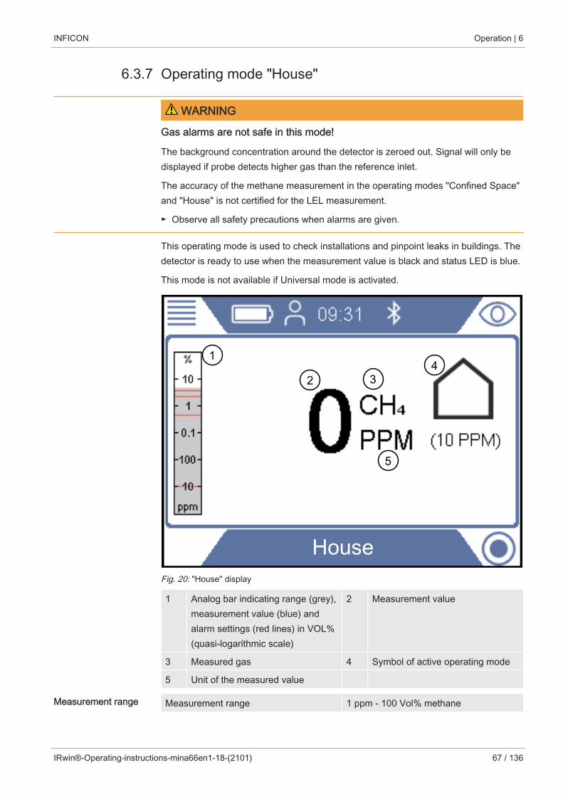
INFICON Operation | 6
IRwin®-Operating-instructions-mina66en1-18-(2101) 67 / 136
6.3.7 Operating mode "House"
WARNING
Gas alarms are not safe in this mode!
The background concentration around the detector is zeroed out. Signal will only bedisplayed if probe detects higher gas than the reference inlet.
The accuracy of the methane measurement in the operating modes "Confined Space"and "House" is not certified for the LEL measurement.
► Observe all safety precautions when alarms are given.
This operating mode is used to check installations and pinpoint leaks in buildings. Thedetector is ready to use when the measurement value is black and status LED is blue.
This mode is not available if Universal mode is activated.
House
1
2 34
5
Fig. 20: "House" display
1 Analog bar indicating range (grey),measurement value (blue) andalarm settings (red lines) in VOL%(quasi-logarithmic scale)
2 Measurement value
3 Measured gas 4 Symbol of active operating mode
5 Unit of the measured value
Measurement range Measurement range 1 ppm - 100 Vol% methane

6 | Operation INFICON
68 / 136 IRwin®-Operating-instructions-mina66en1-18-(2101)
6.3.8 Operating mode "Gas Purity”This mode is intended for checking that the gas has reached a certain point in thenetwork when a previously purged section is refilled.
This mode is not available if Universal mode is activated.
WARNING
No gas alarms are given in this operation mode!
This operating mode is intended for the measurement of higher gas concentrations. Inthis mode you usually see up to 100 Vol% methane.
► Follow all relevant safety precautions and regulations.
Gas Purity
5
12 3 4
6
0 7
Fig. 21: “Gas Purity” display
1 Analog bar indicating range (grey)and measurement value (blue) inVol% (quasi logarithmic scale)
2 Measurement value
3 Measured gas 4 Symbol of active operating mode
5 Unit of the measured value 6 C2H6 compensation value
7 Zeroing button, if needed. Zeroingsymbol disappears if gas isdetected.

INFICON Operation | 6
IRwin®-Operating-instructions-mina66en1-18-(2101) 69 / 136
Measurement range Measurement range 0.1 - 100 Vol% methane
You can readjust the zero point of the CH4 Vol% value if needed. This can be done ifdeviation is within ± 5 Vol%. Press lower left button if "0" appears in blue.
Deviation outside ± 5 Vol% is an indication that the system needs to be calibrated.

6 | Operation INFICON
70 / 136 IRwin®-Operating-instructions-mina66en1-18-(2101)
6.3.9 Operating mode "Ex"This operating mode is used to check or monitor the fire or explosion risk in theworking environment. The concentration of the gas is given in % LEL. A signal of100% LEL or higher (> % LEL) means there is a risk of fire.
This mode is not available if Universal mode is activated.
WARNING
Explosion risk
The concentration can be much higher at another point close by.
► Be aware that the displayed concentration represents the concentration at the gasinlet point of the probe.
The leak detector is ready to use when the measurement value is black and the statusLED is green and the acoustic alive signal beeps every 20 seconds. See warning text.
Ex
31
2
5
4
0 6
Fig. 22: “Ex” display
1 Analog bar indicating range (grey),measurement value (blue) andalarm settings (red lines) in Vol%(quasi-logarithmic scale)
2 Measurement value
3 Measured gas 4 Symbol of active operating mode
5 Unit of the measured value 6 Zeroing button, if needed. Zeroingsymbol disappears if gas isdetected.

INFICON Operation | 6
IRwin®-Operating-instructions-mina66en1-18-(2101) 71 / 136
±Measurement range Measurement range 1 - 100 %LEL methane
You can readjust the zero point of the %LEL value if needed. This can be done ifdeviation is within ± 5 %LEL. Press lower left button if "0" appears in blue.
Deviation outside ± 5 %LEL is an indication that the system needs to be calibrated.
If required, change the primary target gas from methane (CH4) to propane (C3H8) orbutane (C4H10). The leak detector will then recalculate the signals to propane orbutane values using a certified correlation curve.
Use this feature if you need to work on LPG installations.
For changing gas type see "Change gas type for %LEL measurement [} 76]".
WARNING
Explosion risk may exist when "alive" signal not present.
When operating in any of the two safety related modes Ex and Ex Tox respectively,the leak detector will confirm its proper function with a short acoustic "alive" signalevery 20 s and by the status LED being green.
► Leave hazardous areas immediately if the alive signal does not sound every 20 s.
► Do not use the leak detector until it operates normally again.
Status LED
Keep an eye on the status LED when working in either of the safety certified modesEx or Ex Tox. The LED is green when the leak detector works properly and no gasalarm is activated.
Listen also for the acoustic “alive signal” that beeps every 20 s to indicate normaloperation if there are no gas alarms.
The status LED changes to red when a gas alarm is triggered or an error exists.Status LED is yellow in special states such as when in setting menus or calibrationetc. Blue status LED means normal operation in all other modes.

6 | Operation INFICON
72 / 136 IRwin®-Operating-instructions-mina66en1-18-(2101)
Ex The acoustic signal and the status LED are the primary alarm signals. All gas alarmshave a latching function. After a gas alarm is triggered, a check mark key appears inthe upper right corner of the display.
You can mute the acoustic alarm by pressing the check mark key. The alarm willcome on again if a new alarm is triggered.
After the leak detector has been exposed to high methane concentrations, it oftendisplays increased measurement values in the ppm range for a few minutes. This is anormal behavior of the leak detector due to gas residues inside the leak detector.

INFICON Operation | 6
IRwin®-Operating-instructions-mina66en1-18-(2101) 73 / 136
6.3.10 Operating mode "Ex Tox”This operation mode is used to monitor and warn for explosive and toxic gasconcentrations as well as oxygen deficiency in the working area.
Ex Tox
21.6% O2 0.05% CO2
0.0 ppm H S2 0 ppm CO
0CH4
%LEL
12 3 4
5
6
0 67
Fig. 23: “Ex Tox” display
1 Analog bar indicating range (grey),measurement value (blue) andalarm settings (red lines) offlammable gas in Vol% (quasi-logarithmic scale)
2 Measurement value
3 Measured gas 4 Symbol of active mode
5 Unit of the measured value 6 Measurement values of toxicgases and oxygen in ppm and Vol% respectively
7 Zeroing button, if needed. Zeroingsymbol disappears if gas isdetected.
The leak detector shows the gas concentrations of CH4, CO2, CO, H2S and O2.

6 | Operation INFICON
74 / 136 IRwin®-Operating-instructions-mina66en1-18-(2101)
Measurement range Gas Measurement range
CH4, C3H8 or C4H10 1 - 100% LEL
CO2 0.1 - 5 Vol%
CO 1 - 500 ppm
H2S 1 - 400 ppm
O2 0.1 - 25 Vol%
Table 18: Measurement range
You can readjust the zero point of the %LEL value if needed. This can be done ifdeviation is within ± 5 %LEL. Press lower left button if "0" appears in blue.
Deviation outside ± 5 %LEL is an indication that the system needs to be calibrated.
If desired you can change the primary target gas from methane (CH4) to propane(C3H8) or butane (C4H10). The leak detector will then recalculate the signals to propaneor butane values using certified correlation curves.
Use this feature if you need to work on propane or butane installations.
For changing gas type see "Change gas type for %LEL measurement [} 76]".
WARNING
Explosion risk may exist when "alive" signal not present.
When operating in any of the two safety related modes Ex and Ex Tox respectively,the leak detector will confirm its proper function with a short acoustic "alive" signalevery 20 s and by the status LED being green.
► Leave hazardous areas immediately if the alive signal does not sound every 20 s.
► Do not use the leak detector until it operates normally again.
Status LED
Keep an eye on the status LED when working in either of the safety certified modesEx or Ex Tox. The LED is green when the leak detector works properly and no gasalarm is activated.
Listen also for the acoustic “alive signal” that beeps every 20 s to indicate normaloperation if there are no gas alarms.
The status LED changes to red when a gas alarm is triggered or an error exists.Status LED is yellow in special states such as when in setting menus or calibrationetc. Blue status LED means normal operation in all other modes.
Ex Tox The acoustic signal and the status LED are the primary alarm signals. All gas alarmshave a latching function. After a gas alarm is triggered, a check mark key appears inthe upper right corner of the display.

INFICON Operation | 6
IRwin®-Operating-instructions-mina66en1-18-(2101) 75 / 136
You can mute the acoustic alarm by pressing the check mark key. The alarm willcome on again if a new alarm is triggered.
After the leak detector has been exposed to high methane concentrations, it oftendisplays increased measurement values in the ppm range for a few minutes. This is anormal behavior of the leak detector due to gas residues inside the leak detector.
NOTICE
Measuring of high gas concentrations of H2S or CO reduces sensor life time.
Frequent measuring of high gas concentrations will reduce the life time of the sensorsfor the detection of toxic gases.
Set Time WeightedAverage (TWA)
The leak detector has a TWA-Function (Time Weighted Average Function) with whichalarms can be given according to LTEL (Long Term Exposure Limit) or STEL (ShortTerm Exposure Limit). The LTEL value and the STEL value correspond to themaximum dose of a substance to which a person should be exposed over a definedperiod.
• STEL is the weighted average value over 15 minutes (for the respective toxic gas).
• LTEL is the weighted average value over 8 hours (for the respective toxic gas).
To set the Alarm Level for LTEL and STEL, see "Set limits and alarm levels [} 46]".
NOTICE
The TWA calculations are reset when you switch from Ex Tox to another operatingmode.
For changing gas type see "Change gas type for %LEL measurement [} 76]".

6 | Operation INFICON
76 / 136 IRwin®-Operating-instructions-mina66en1-18-(2101)
6.3.10.1 Change gas type for %LEL measurementü Login as Intermediate or Advanced
► > > General > Misc (Tab) > Select gas
ð Choose between methane (CH4), propane (C3H8) or butane (C4H10).
This option is only valid for the LEL measurement (operating modes Ex and Ex Tox).

INFICON Operation | 6
IRwin®-Operating-instructions-mina66en1-18-(2101) 77 / 136
6.3.11 IR Ethane Analysis and compensation
Incorrect Ethane compensation value can result in significant deviation in theestimated methane concentration, in the operating modes "Above Ground", "BarHole", "House" and "Gas Purity".
Why an IR EthaneAnalysis?
This function is mainly used to distinguish between natural gas and swamp gas fromunderground biological decay. Natural gas contains varying concentrations of ethanewhile swamp gas does not.
Such analysis is traditionally made with a gas chromatograph. With IRwin the sameanalysis with similar sensitivity is performed much faster. Instead of the typical 5 to 10minutes a gas chromatograph requires for an analysis IRwin only needs a fewseconds.
The second purpose of the GC Ethane Analysis is to establish the ethaneconcentration for compensation at high methane levels.
The GC Ethane Analysis can be made from below 1 to 8 Vol% ethane in the naturalgas. The resolution is 0.1% and the accuracy better than 1 Vol%.
INFICON single-cellwide range technology(patent-pending)
IRwin methane leak detector employs the unique INFICON single-cell wide rangetechnology to detect all concentrations from 1 ppm to 100 Vol% methane. Thistechnology is very sensitive to the ethane content in the natural gas. Therefore, largedeviations can occur at higher gas concentrations if the ethane concentration is notcompensated for.
The leak detector has a built-in routine for ethane compensation. The ethane contentcan be entered manually, if known. A more practical way is to use the GC EthaneAnalysis function to measure the ethane content and automatically set thecompensation concentration. The safety certified modes Ex and Ex Tox are notaffected by this phenomenon.
IRwin SXG and SXGT models also have GC Ethane Analysis capability fordistinguishing between Natural gas (NG), liquid petroleum gas (LPG) and swamp gasby determining the presence of methane, ethane and propane in the sampled gas.
The GC Ethane Analysis function is not affecting the ethane compensation.

6 | Operation INFICON
78 / 136 IRwin®-Operating-instructions-mina66en1-18-(2101)
6.3.11.1 Entering ethane concentration manuallyIf you know the current ethane concentration in your natural gas you can enter thisvalue manually. We recommend, however, that you use the built-in GC EthaneAnalysis to determine the ethane concentration as this typically varies from day to dayand from location to location.
ü Login as Intermediate or Advanced
1 > > IR Ethane Analysis > Settings (Tab)
2 Select "Ethane (%) for Compensation".
3 Set the desired ethane concentration.
ð The value shown is the current setting. The last value (indicated by an “A”) isthe result of the last IR Ethane Analysis.
4 Leave the view via .
6.3.11.2 Setting reminder for IR Ethane AnalysisYou can set the detector to remind you to make an IR Ethane Analysis. If set, thedetector will ask if you want to perform a new IR Ethane Analysis or keep the currentvalue.
1 > > IR Ethane Analysis > Settings (Tab)
2 Select ”Reminder for Ethane Compensation Analysis”.
3 Select between the following settings:
Off No reminder
Start-up Reminder first time you enter "Bar Hole"mode after start-up of detector (10 sdelay)
Always Reminder every time you enter "BarHole" mode (10 s delay).
Table 19: Setting reminder for IR Ethane Analysis
INFICON Operation | 6
IRwin®-Operating-instructions-mina66en1-18-(2101) 79 / 136
6.3.11.3 Performing IR Ethane Analysis after automatic reminderYou need a methane concentration in the range of 5 to 15 Vol% to perform the IREthane Analysis. The compensation is only needed for high gas concentrations and istherefore only needed when you have found a significant leak.You should connect the Bell probe before performing the IR Ethane Analysis.
1 Change to operating mode "Bar hole".
ð If reminder is activated a window will appear showing the current ethaneconcentration setting. The leak detector asks if you want to keep the currentvalue or a make a new analysis.
2 Select "New” and press the bell firmly down onto the place where you found thegas.
ð A number between 0 and 100 appears on the display.
3 If the value is smaller than 20, push the probe harder onto the surface or lookfor a place with higher methane concentration. If the value is higher that 80 youshould move the bell away from the leak to find a spot with lower concentration.
ð Try to make the signal stabilize at a value between 20 and 80. Whensucceeding, the detector will need another 2-3 seconds to calculate the ethaneconcentration. The result is displayed as % C2H6.
ð Press check mark to continue. IRwin will ask if you want to "Save EthaneConcentration for Compensation".
ð Select "No" if analysis was made for confirming natural gas or "Yes" to use forcompensation. If selecting "Yes" the value is saved as ethane concentration andshown in the C2H6 field.See Operating mode “Bar Hole” [} 58].
ð An ethane concentration value of 1 % or higher is a safe indication of naturalgas. A value between 0.4 and 1 % is a probable indication of natural gas.
If the measured ethane values are between 0 and 2% it is recommended that yourepeat the measurement at least 3 times on the same position to check the result isconsistent.

6 | Operation INFICON
80 / 136 IRwin®-Operating-instructions-mina66en1-18-(2101)
6.3.11.4 Starting IR Ethane Analysis manually1 > > IR Ethane Analysis > Start (Tab)
2 Press button next to check mark to start.
3 Press the bell firmly down onto the place where you found the gas.
ð A number between 0 and 100 appears on the display.
4 If the value is smaller than 20, push the probe harder onto the surface or lookfor a place with higher methane concentration. If the value is higher that 80 youshould move the bell away from the leak to find a spot with lower concentration.
ð Try to make the signal stabilize at a value between 20 and 80. Whensucceeding, the detector will need another 2-3 seconds to calculate the ethaneconcentration. The result is displayed as % C2H6.
ð Press check mark to continue. IRwin will ask if you want to "Save EthaneConcentration for Compensation".
ð Select "No" if analysis was made for confirming natural gas or "Yes" to use forcompensation. If selecting "Yes" the value is saved as ethane concentration andshown in the C2H6 field.See Operating mode “Bar Hole” [} 58].
ð An ethane concentration value of 1 Vol% or higher is a safe indication of naturalgas. A value between 0.4 and 1 Vol% is a probable indication of natural gas.
If the measured ethane values are between 0 and 2% it is recommended that yourepeat the measurement at least 3 times on the same position to check the result isconsistent.
6.3.11.5 Viewing IR Ethane Analysis infoDisplay the date of the last IR Ethane Analysis as follows.
► > > IR Ethane Analysis > Info (Tab)
ð The date and the time of the last C2H6 Analysis will be shown.
ð IRwin SXG and SXGT will also show the time of the last IR Ethane Analysis.

INFICON Operation | 6
IRwin®-Operating-instructions-mina66en1-18-(2101) 81 / 136
6.3.12 Calibration (adjustment)
Calibration is interpreted differently in different countries and applications.Throughout this document we therefore use the following definitions:
Function Test: Exposing to given gas(es) checking if accuracy of a certainmeasurement is within specified accuracy and to judge weather calibration adjustmentis needed.
Calibration: Exposing to given gas(es) and, if required, automatically adjusting thedetector to display the given concentration within specified accuracy.
The built-in calibration routines guide you through the adjustment of the leak detectorsensitivity to the various test gases. You can set calibration intervals for the differentadjustments and will then get a reminder when calibration is due ("Adjust calibrationreminder").
The description below cover all possible modes. Only part of them are activateddepending on he actual setting of the detector.
Allow IRwin to warm up for 1 hour before calibrating for best accuracy.
The calibration intervals recommended for the operating modes Ex and Ex Tox arebased on the TÜV certificates for these operating modes. For the other modes thesetime intervals are chosen to give you the best performance. In any case you shoulduse the results of the various function tests to judge whether a calibration is needed. Ifyou want to perform more than one calibration procedure at a given time you shouldrun them in the following sequence for best performance.
1. Above Ground if Universal mode is disabled
2. Universal (low range) if Universal mode is enabled
3. Ex CH4 (IRwin SX, SXT, SXG and SXGT only)
4. Tox (IRwin SXT and SXGT only)
5. Bar Hole CH4 or Universal (high range) if Universal mode is enabled
6. Bar Hole CO2 or Universal (20% CO2) if Universal mode is enabled
Recommended calibration check intervals
• Above Ground CH4 - weeklyWith this calibration you calibrate the higher range (Vol%) of the modes Houseand Bar Hole at the same time.
• Universal (low range) - weeklyFor calibration adjustment of Universal (low range) you need one, two or threegases as specified in section “Concentration of calibration and test gases”, seeConcentration of calibration and test gases [} 34].

6 | Operation INFICON
82 / 136 IRwin®-Operating-instructions-mina66en1-18-(2101)
• Tox - weeklyFor calibration in Ex Tox mode you need Tox mix.The CO2 calibration of other modes is not affected. CH4 of the operation mode Exis also calibrated during the Ex Tox calibration. However, for best performance, itis recommended to perform the Ex calibration after the Ex Tox calibration.
• Ex CH4 - weeklyFor calibration in Ex mode you need the following gas concentrations:2.2% CH4.
• Bar Hole CO2 / Universal (20.0% CO2) - monthlyFor calibration of the CO2 measurement of Bar Hole you need the following gasconcentrations: 20% CO2.
This calibration does not influence the toxic CO2 calibration (ppm) in the Ex Toxcalibration routine.
• Bar Hole CH4 / Universal (high range) - monthlyFor calibration of the CH4 measurement of Bar Hole you need the following gasconcentrations:2.2% CH4, 100% CH4.
Beside the calibrations of the application mode “Bar Hole” the application modes“Gas Purity” and “Confined Space” will be calibrated in the higher measurementrange (Vol%), too.
• GC Ethane Analysis (normally not required)Calibration of the GC is normally done after service to the GC but can also bedone if the GC graphs look abnormal. This can be the case if the GC sensor hasbeen subjected to high gas concentrations.GC calibration is done using 50 %LEL CH4 (2.2 or 2.5 Vol% depending on LELsetting) and is only accessible if logged in as advanced user.For full functionality you must perform a GC Function Test directly after performinga GC calibration.
WARNING
Explosion, asphyxiation, toxic risk
Incorrect calibration leads to incorrect measurement results. Thus you are not properlywarned against any possibly dangerous gas concentrations.
► Calibrate the leak detector only when you have been properly trained.
► Calibrate the detector in well ventilated rooms or outdoors.

INFICON Operation | 6
IRwin®-Operating-instructions-mina66en1-18-(2101) 83 / 136
The methane calibration is possible with gas mixtures in synthetic air only.
The natural background of CO2 (typically 400 ppm) in ambient air will offset thecalibration.
Fresh air exposure should, however, always be by ambient air.
After the leak detector has been calibrated with 100% methane it shows a few ppmincrease in the measured value for a few minutes. This is a normal behavior of theleak detector and due to gas residues inside the leak detector.
Retrieving informationabout the calibration
The leak detector saves the date and the time of the last successful calibration.
► > > Calibration > Info (Tab)

6 | Operation INFICON
84 / 136 IRwin®-Operating-instructions-mina66en1-18-(2101)
6.3.12.1 Standard calibration proceduresPrepare calibration For a complete calibration you need the gases listed, see "Concentration of calibration
and test gases [} 34]".
It is not necessary that you calibrate all modes at the same time.
Mode
Calibration Routine
AboveGround
Universal(low range)
Ex Tox Bar Hole
CH4
Universal(high range)
Bar Hole
CO2
Universal(CO2)
Above Ground X
Universal (lowrange)
X
Bar Hole X X
Universal (highrange)
X X
Plants X
House X
Gas Purity X
Ex X X*
Tox X*
Table 20: Standard calibration procedures
*Ex Tox calibration routine also calibrates Ex mode.
No need to run Ex calibration routine separately if Ex Tox calibration has beenperformed.
GC calibration of the timing of the different peaks can be made when logged in asAdvanced user. Peak height is not calibrated and should not be used as indication ofthe concentration.
Calibrate Above Ground / Universal (low range) first for best performance.
We strongly recommend using so called ODFRs (On Demand Flow Regulators) toadministrate calibration and test gases to the instrument. These regulatorsautomatically supplies the exact gas flow aspired by the instrument and automaticallyshuts off when disconnected from the sample input.
It is also possible to use other calibration stations for the calibration. However, thefollowing requirements have to be fulfilled.

INFICON Operation | 6
IRwin®-Operating-instructions-mina66en1-18-(2101) 85 / 136
• The gas flow delivered by the calibration station must be higher than the flowaspired by the leak detector. Set the gas flow to at least 80 l/h.
• The gas must be delivered at ambient pressure (i.e., do not push gas into the leakdetector). The normal way to accomplish this is to create an open connectionbetween gas container and detector inlet so that the excess calibration gas isvented to the ambient. This exhaust should be placed outside the test room,preferably outdoors.
Calibration ü Login as Intermediate or Advanced
► > > Calibration > Calibration (Tab)
ð Select the calibration to perform and click the check mark button.
ð The leak detector leads you through the process by indicating which gas todeliver to the detector in each step. Make sure that no residual gases arepresent in the ambient during Fresh Air step. Most common problems occur ifyou used 2.2 Vol% or 100 Vol% methane shortly before the trying to calibratewith 10 ppm or 100 ppm methane.
ð A successful calibration is confirmed by a green check mark.
ð A failed calibration is indicated by a red cross.
You can continue to use the leak detector even if calibration failed. The previouscalibration parameters are restored.
6.3.12.2 Setting of calibration gas concentrations
Accuracy can be affected by calibration gas tolerance.
For optimum performance adjust the concentrations of the calibration gases set in theleak detector to the actual composition of your calibration gases.
For optimum performance of your leak detector you should use the proposedcalibration gases. The exact concentrations of the gas delivered often deviates slightlyfrom these values due to tolerance factors etc. The exact value is typically stated onthe analysis certificate of the respective gas. You should therefore adjust theconcentrations of the calibration gases set in the detector to match the actualcomposition of your calibration gases, see "Concentration of calibration and test gases[} 34]".
ü Login as Intermediate or Advanced
1 > > Calibration > Settings (Tab)
2 Select calibration routine first and then select the gas to adjust (if several).
3 Confirm your selection with .
ð A window appears with controls for adjusting the gas selected.

6 | Operation INFICON
86 / 136 IRwin®-Operating-instructions-mina66en1-18-(2101)
4 Set the exact gas concentration value via drop-down menus. The leak detectorshows the gas to adjust in the window and the currently stored concentrationappears just below the setting line. You cannot set the concentration outside therange.
5 Select "Set" to confirm new value or "Reset" to restore the default value.
If changing a calibration gas concentration you must check if the same gas is used inseveral calibration routines.
If so, you must adjust the concentration of that gas in all relevant routines.
6.3.12.3 Adjust calibration reminderYou can set an Interval for a calibration reminder for each of the calibration types. TheInterval is set to Off as default, meaning no reminder.
Unless required by the relevant regulations there is no need to calibrate (includesadjustement) if function test for that specific mode passes.
Activate calibrationreminder
ü Login as Intermediate or Advanced
1 > > Calibration > Interval (Tab)
2 Select the operation mode for which you want to set a calibration reminder andset the desired period of time.
3 Leave the view via .
The leak detetctor saves the set period of time automatically.

INFICON Operation | 6
IRwin®-Operating-instructions-mina66en1-18-(2101) 87 / 136
6.4 Performing function tests
Correct readings only if settings are correct.
If the leak detector does not work correctly, it may not show every leak.
► Test the leak detector regularly as recommended.
Function tests are available for all tasks of the detector.
Some of these tests are typically called "bump tests".
Use the Function tests to test the status and accuracy of the leak detector. The leakdetector will guide you through the test procedures and tell you when operator actionsare needed.
Passing the function test means that specific detector function performs as specified.No adjustment (in this context called Calibration) is needed for that specific function.
Repeated failure of a function test is an indication that the detector needs calibrationfor that particular function. See Calibration (adjustment) [} 81].
Once you have set the function test intervals, the leak detector will remind you toperform the respective Function test, see "Setting the Function Test interval".
RecommendedFunction test intervals(based on IRwinmodel)
• Before starting work / bump testing
For leak surveys we recommend performing a 10 ppm bump test before startingsurvey. This is required by German DVGW and local regulations in several othercountries. If your survey limit is higher or you are using IRwin for another purposeit is possible to use either 500 ppm or 2.5 Vol% instead. Select desired gas byadjusting the function test gas. See, Universal Fnc Test conc / AbG Fnc Test conc[} 49].
• Ex: 2.2 - 2.5 Vol% CH4 depending of country
• Ex Tox: Daily (2.2% CH4, CO2, CO, O2, H2S)
We strongly recommend using so called ODFRs (On Demand Flow Regulators) toadministrate calibration and test gases to the instrument. These regulatorsautomatically supplies the exact gas flow aspired by the instrument and automaticallyshuts off when disconnected from the sample input.
It is also possible to use other calibration stations for the calibration. However, thefollowing requirements have to be fulfilled.
• The gas flow delivered by the calibration station must be higher than the flowaspired by the leak detector. Set the gas flow to at least 80 l/h.

6 | Operation INFICON
88 / 136 IRwin®-Operating-instructions-mina66en1-18-(2101)
• The gas must be delivered at ambient pressure (i.e., do not push gas into the leakdetector). The normal way to accomplish this is to create an open connectionbetween gas container and detector inlet so that the excess calibration gas isvented to the ambient. This exhaust should be placed outside the test room,preferably outdoors.
ü To perform the Function test, you need fresh air and either 10 ppm CH4 or 50% LELCH4 in synthetic air. For IRwin SXT and SXGT you will also need the ToxMix gasmixture.
1 Check the leak detector for visible damage.
2 > > Function Test > Test (Tab)
3 Select the desired function test from the list.
4 Start the selected Function test by pressing .
ð The leak detector guides you through the process.
You can display the date of the last function test.
► > > Function Test > Info (Tab)
This time is the basis for the next function test reminder. Refer to "Setting the FunctionTest interval".
Function tests are optimized for factory default concentrations. Using otherconcentrations, even if within the adjustable calibration or function test concentrationrange, can make the automatic function test interpretation invalid.
If you fail function test and you are using non-standard gases we recommend that youtest the instrument by simply exposing the respective mode for the test gas andobserve the reading. This way you can still verify the function but the last passedfunction test will not be logged if automatic interpretation failed.
INFICON Operation | 6
IRwin®-Operating-instructions-mina66en1-18-(2101) 89 / 136
6.5 Measuringü Connect the leak detector to the desired probe. See "Function [} 14]".
1 Switch on the leak detector by pressing the I/O key.
2 Complete the self test.
3 Make sure that the desired basic settings are correct. See "Startup Settings[} 43]".
4 Make sure that the settings for the desired operating mode are correct. See"Operating modes [} 54]".
5 Switch to the desired operating mode.
6 Consider all relevant regulations for the operation in question.
7 Record the measured values if desired. See "Logging data to file [} 90]".
8 Start measuring.
6.6 Perform self testWhen you turn on the leak detector it will automatically perform a self test for the maincomponents such as software and parameter memories, battery, gas sensors,valve(s), pumps, buzzer and status LED.
If not all test are passed successfully it may be that some operating modes cannotwork properly. That is indicated by the status LED being yellow. The test can, forexample, fail because you accidentally blocked an inlet during the test.
If the problem has been solved it is possible to re-start the self test sequence and getthe detector into normal operation mode without having to re-start the completesystem.
► > > Function Test > Test (Tab)
To understand more about the causes of test failure and the leak detector staying in aspecial state see “Warnings and error messages [} 90]".
6.7 Viewing Status menuYou are able to read the current status of the self diagnostic functions of the system ina menu.
When troubleshooting or contacting the service, use this information.
► > > Status

6 | Operation INFICON
90 / 136 IRwin®-Operating-instructions-mina66en1-18-(2101)
6.8 Logging data to fileIRwin can log data in all operating modes. This is especially practical to save datafrom leak surveys in Above Ground mode.
Starting/stopping thedata logging.
ü You have configured the data logging, see "Configure data logging [} 50]".
ü You have set the leak detector in operating mode Above Ground.
1 To start or stop the logging press or in the measurement screen.
2 Confirm your choice.
Deleting files is only possible with IRwin App software, see Transfer data to computer.
6.9 InformationDuring operation, the display shows information that helps you operate the leakdetector. Activated operation mode, warnings and error messages are shown inaddition to the measurement values.
The leak detector is equipped with extensive self-diagnostic functions. If theelectronics detect an incorrect state, the leak detetcor displays this as far as possibleand interrupts operation when necessary.
6.9.1 Retrieve information and statisticsCall up detectorinformation
1 > > ABOUT.
2 Leave the view via .
Call up statistics 1 > > STATISTICS
2 Leave the view via .
6.9.2 Warnings and error messagesWarnings Warnings are given for conditions that can impair the accuracy of measurements. The
operation of the leak detector is normally not interrupted but some functions may bebarred or indicated as non-compliant by status LED being yellow and values being redinstead of black.
If the navigation button “Menu“ is colored red this means that there has been anerror that you have not yet checked. If the cause of the error remains there will be anew warning/error alarm and a new entry in the error log. The navigation button turnsblue again when you have read the warnings list.
Open the warnings log list:
► > > Warnings

INFICON Operation | 6
IRwin®-Operating-instructions-mina66en1-18-(2101) 91 / 136
Error messages Errors are events that force the interruption of the operation. Errors are also logged inthe warnings log list.
The division between errors and warnings is sometimes not very clear. In both cases itis worth restarting the detector to try to pass the self -test again. Charging the batteryalso reduces the risk for some errors and warnings.
No. Message Possible error sources Remedy
Warnings
- Red LED / Constantbeep
HW Watchdog triggered Perform hard switch off.
Restart detector.
If problems remains: Contact INFICON service.
W2 Reference Inlet Blocked Reference inlet blocked Check that nothing is blocking the inlet.
Reference inlet filterclogged
Contact INFICON service.
W3 Sample Inlet Blocked Sample inlet blocked Check that nothing is blocking the inlet
Sample inlet filter blocked Replace cigarette filter in sample inlet.
Blockage in accessory Disconnect accessory. If alarm disappears: Check accessory.
Internal filter blocked Disconnect accessories.If alarm remains: Contact INFICON service.
W4 Exhaust Blocked Exhaust blocked Check that nothing is blocking the exhaust.If alarm remains: Contact INFICON service.
W5 O2 sensor error System error Restart detector.If problems remains: Contact INFICON service.
W6 O2 sensor error System error Restart detector.If problems remains: Contact INFICON service.
W7 H2S sensor error System error Restart detector.If problems remains: Contact INFICON service.
W8 H2S sensor error System error Restart detector.If problems remains: Contact INFICON service.
W9 CO sensor error System error Restart detector.If problems remains: Contact INFICON service.
W10 CO sensor error System error Restart detector.If problems remains: Contact INFICON service.
W11 CH4 sensor error System error Restart detector.If problems remains: Contact INFICON service.
W12 CH4 sensor error System error Restart detector.If problems remains: Contact INFICON service.

6 | Operation INFICON
92 / 136 IRwin®-Operating-instructions-mina66en1-18-(2101)
No. Message Possible error sources Remedy
W13 CO2 sensor error System error Restart detector.If problems remains: Contact INFICON service.
W14 CO2 sensor error System error Restart detector.If problems remains: Contact INFICON service.
W17 H2S STEL levelreached, (STEL andlimit shown,Confirm)
Short Term Exposurealarm for H2S.
Normal function.If warning reapperas without any gas present:Recalibrate TOX mode.If still reappearing: Contact INFICON service
W18 H2S LTEL levelreached, (LTEL andlimit shown,Confirm)
Long Term Exposurealarm for H2S.
Normal function.If warning reapperas without any gas present:Recalibrate TOX mode.If still reappearing: Contact INFICON service
W19 CO STEL levelreached, (STEL andlimit shown,Confirm)
Short Term Exposurealarm for CO
Normal function.If warning reapperas without any gas present:Recalibrate TOX mode.If still reappearing: Contact INFICON service
W20 CO LTEL levelreached, (LTEL andlimit shown,Confirm)
Long Term Exposurealarm for CO
Normal function.If warning reapperas without any gas present:Recalibrate TOX mode.If still reappearing: Contact INFICON service
W21 CO2 STEL levelreached, (STEL andlimit shown,Confirm)
Short Term Exposurealarm for CO2.
Normal function.If warning reapperas without any gas present:Recalibrate TOX mode.If still reappearing: Contact INFICON service
W22 CO2 LTEL levelreached, (LTEL andlimit shown,Confirm)
Long Term Exposurealarm for CO2.
Normal function.If warning reapperas without any gas present:Recalibrate TOX mode.If still reappearing: Contact INFICON service
Error messages
E1 Main Pump error Exhaust blocked Check that nothing is blocking the exhaust.
If alarm remains: Contact INFICON service.
Reference inlet blocked Check that nothing is blocking the reference inlet.
If alarm remains: Contact INFICON service.
Pump dirty or broken Contact INFICON service.
E2 Sample Pump error Sample pump not running Restart detector.
If problems remains: Contact INFICON service.
E3 IR Lamp error IR Lamp error Restart detector.
If problems remains: Contact INFICON service.

INFICON Operation | 6
IRwin®-Operating-instructions-mina66en1-18-(2101) 93 / 136
No. Message Possible error sources Remedy
E4 IR Lamp error IR lamp supply error Restart detector.
If problems remains: Contact INFICON service.
E5 Battery level too low(count down to poweroff)
Battery low Switch off detector and charge battery
E7 SnO2 voltage error System error Restart detector.
If problems remains: Contact INFICON service.
E8 Detector shuts down System error Restart detector.
If problems remains: Contact INFICON service.
E9 Red LED and constantbeep
HW watchdog trigged Perform hardware reset.
Restart detector.
If problems remains: Contact INFICON service.
E10 O2 Sensor bias lost O2 sensor bias lost dueto uncontrolled shutdown.
Check in Ex Tox mode that O2 value is OK (closeto 20.9%). If not, leave the detector on until O2sensor shows 20 - 22% in air. This can take up to12 hours.
E11 “IR Lamp" has redcross in function testresult screen.
IR system error Restart detector.
If problems remains: Contact INFICON service.
E12 “Pump & Valve" testhas red cross infunction test resultscreen.
Exhaust blocked Restart detector.
If problems remains: Contact INFICON service.
Pump dirty or broken Contact INFICON service.
E13 “Pump & Valve" testhas red cross infunction test resultscreen.
Valve clogged Restart detector.
If problems remains: Contact INFICON service.
System error Restart detector.
If problems remains: Contact INFICON service.
E14 “Pump & Valve" testhas red cross infunction test resultscreen.
Exhaust blocked Check that nothing is blocking the exhaust.
If alarm remains: Contact INFICON service.
Reference inlet blocked Check that nothing is blocking the reference inlet.
If alarm remains: Contact INFICON service.
Pump dirty or broken Contact INFICON service.
E15 "Gas Sensors" has redcross in function testresult screen.
Sensor error or warm-updrift
Restart detector.
If problems remains: Contact INFICON service.
E16 "Gas Sensors" has redcross in function testresult screen.
Sensor error or warm-updrift
Restart detector.
If problems remains: Contact INFICON service.

6 | Operation INFICON
94 / 136 IRwin®-Operating-instructions-mina66en1-18-(2101)
No. Message Possible error sources Remedy
E17 "Gas Sensors" has redcross in function testresult screen.
Sensor error or warm-updrift
Restart detector.
If problems remains: Contact INFICON service.
E18 "Buzzer" has red crossin function test resultscreen.
Buzzer "hole" blocked orfilled with water
Dry and clean buzzer hole.
Restart detector.
If problems remains: Contact INFICON service.
E19 "LED" has red cross infunction test resultscreen.
LED broken Contact INFICON service.
E20 RAM test error (Poweroff)
Memory damaged or testerror
Restart detector.
If problems remains: Contact INFICON service.
E21 ROM test error (Poweroff)
Memory damaged or testerror
Restart detector.
If problems remains: Contact INFICON service.
E22 CRC error (power off) Memory damaged or testerror
Restart detector.
If problems remains: Contact INFICON service.
E23 "Gas Sensors" has redcross in function testresult screen.
Sensor error or warm-updrift
Restart detector.
If problems remains: Contact INFICON service.
E24 No message given Service info only No action needed.
E25 Surroundingtemperature is outsideof rated temperature.Function might beaffected
Instrument temperature istoo high or to low
Explosion protection cannot be guaranteed. Immediately move detector to cooler place orswitch OFF if flammable gases could be present.
Table 21: Warnings and error messages
6.9.3 Viewing the Service ScreenOn the service screen you will find details about sensor signals and monitored supplyvoltages, for example. During contact with the service department this could be useful.
ü Login as Advanced
► > > Service Screen
6.10 Switching OFFSwitching OFF 1 Press the "On / Off” key for 3 seconds.
ð The leak detector asks whether you want to switch off the instrument.
2 Select “Yes” and press the check mark key.

INFICON Operation | 6
IRwin®-Operating-instructions-mina66en1-18-(2101) 95 / 136
Hard switch off Some errors can make the leak detector go into watchdog state. The acoustic alarmbeeps continuously and the status LED is red. The leak detector may not even bereacting to the menu buttons. If this happens you must turn the leak detector off. Pressand hold the "On / Off” key until the detector shuts down (roughly 9 s).
Do not use this option without cause. You risk losing settings and the bias of theoxygen sensor on SXT and SXGT models. This leads to a prolonged warm up at nextpower on. It can take up to 12 hours to stabilize the oxygen sensor if sensor bias islost form more than a few minutes. If you need to do a hardware switch off you shouldrestart the leak detector immediately, If the leak detector malfunctions again you willneed to contact INFICON service.
1 Press the "On / Off” key for 9 seconds.
2 Restart the leak detector as soon as possible to restore O2sensor bias (IRwinSXT and SXGT).

7 | Maintenance INFICON
96 / 136 IRwin®-Operating-instructions-mina66en1-18-(2101)
7 MaintenanceThe gas inlet of the instrument, as well as the probe system include various filters.These must be replaced at intervals specified in the maintenance plan. If the leakdetector is used in dirty environments, more frequent replacements may benecessary.
The internal sample inlet filter can become clogged.
Running the leak detector with no probe connected can make the internal filtersclogged. This can cause need for service.
7.1 Maintenance plan
Maintenance cycle Additional information
daily 7.4.2 Change the cigarette filter in the sample inlet
7.5 Maintenance of the hand probe
weekly 7.6 Maintenance of the carpet probe
monthly 7.6 Maintenance of the carpet probe
7.7 Maintenance of the bell probe
7.8 Maintenance of the swan neck
7.9 Maintenance of the bar hole probe
7.2 Spare parts listSpare part Order number Purpose
Filter cartridge 0.45 um 581-704 Carpet
Filter disk OD=8 mm 591-367 Bell
Dust filter, 8612 591-095 Bell, Swan Neck and Flexi Bell
Cigarette Filter 120-pack 581-700 Hand Probe and Sample inlet
Bar Hole Rubber Seal for Bar Hole Probe

INFICON Maintenance | 7
IRwin®-Operating-instructions-mina66en1-18-(2101) 97 / 136
7.3 General check of probe systemThe probe system used must be checked regularly for external damage and leaks.
1 Examine all parts of the probe system for external damages.
2 Check that the rubber grip of the Hand Probe is not broken or missing. The rubber is certified anti-static and must be replaced by original INFICONspare if damaged or missing.
3 Connect the probe system to the instrument.
4 Block the inlet of the probe system.
ð If the error message "Blocked flow alarm" appears, the probe system issufficiently leak-proof. When the leak detector does not show an error there is aleak in the system.

7 | Maintenance INFICON
98 / 136 IRwin®-Operating-instructions-mina66en1-18-(2101)
7.4 Maintenance of the leak detector
7.4.1 Seasonal shut-downIRwin SXT is using a small amount of power when shut off. This allows the clock tocontinue running and the function of oxygen sensor to be maintained for faster warm-up.
When you want to store the leak detectorup to 3 months charge it fully.
When you want to store the leak detector more than 3 months select one of thefollowing possibilities.
Connect the charging equipment and leave the charger on.
OR:
Charge the battery every 3 months as long as you store the leak detector.
7.4.2 Change the cigarette filter in the sample inlet► Change the filter according to the maintenance plan, see Maintenance plan [} 96].
Be careful when checking the cigarette filter in the inlet, make sure that it is notdeformed, otherwise it will loose part of its function. Replace the filter if in doubt.

INFICON Maintenance | 7
IRwin®-Operating-instructions-mina66en1-18-(2101) 99 / 136
7.5 Maintenance of the hand probe
Replace the filter in the tip of the probe according to the maintenance plan, seeMaintenance plan.
Be careful when checking the cigarette filter in the inlet, make sure that it is notdeformed, otherwise it will loose part of its function. Replace the filter if in doubt.
Check that the original rubber grip is in place. Using another rubber grip invalidatesthe certification of explosion protection.
7.6 Maintenance of the carpet probe► Change the inline filter according to the maintenance plan, see Maintenance plan
[} 96].

7 | Maintenance INFICON
100 / 136 IRwin®-Operating-instructions-mina66en1-18-(2101)
7.7 Maintenance of the bell probe
Fig. 24: Flexi Bell
► Change the filter according to the maintenance plan, see Maintenance plan.
1 2 3 4
Fig. 25: Bell Probe
1 Bell 3 O-Ring
2 Paper filter 4 Filter housing
1 Screw off the top of the filter housing.
2 Remove the old paper filter and o-ring.
3 Place the o-ring around end cap on top of the new paper filter.
4 Place the filter and o-ring in the compartment of the filter housing.
5 Screw on the top tightly by hand.
6 Replace the bell probe.

INFICON Maintenance | 7
IRwin®-Operating-instructions-mina66en1-18-(2101) 101 / 136
7.8 Maintenance of the swan neck
Fig. 26: Swan Neck
Change the filter according to the maintenance plan, see Maintenance plan.
See also
2 Maintenance of the bell probe [} 100]
7.9 Maintenance of the bar hole probeRubber needs to be replaced when worn. Contact INFICON.
Fig. 27: Bar Hole Probe

8 | Decommissioning the leak detector INFICON
102 / 136 IRwin®-Operating-instructions-mina66en1-18-(2101)
8 Decommissioning the leak detector
8.1 Sending in the leak detector
WARNING
Danger due to harmful substances
Contaminated equipment can endanger the health. The contamination declarationserves to protect all persons who come into contact with the equipment.
► Fill in the declaration of contamination completely.
1 Please do not hesitate to contact us and send a completed declaration ofcontamination before sending anything to us.
ð You will then receive a return number from us.
2 Use the original packaging when returning.
3 Before sending the instrument attach a copy of the completed contaminationdeclaration. See below or on the homepage of INFICON.

INFICON Decommissioning the leak detector | 8
IRwin®-Operating-instructions-mina66en1-18-(2101) 103 / 136

8 | Decommissioning the leak detector INFICON
104 / 136 IRwin®-Operating-instructions-mina66en1-18-(2101)
8.2 Disposing of the equipmentThe leak detector can either be disposed of by the owner or be sent to themanufacturer. The leak detector contains materials that can be recycled. This optionshould be exercised to prevent waste and also to protect the environment.
During disposal, observe the environmental and safety regulations of your country.
Information for recycling.
The leak detetctor cannot be scrapped with the normal domestic waste.
8.3 Safe battery removal
1 Use a Torx 10 driver to remove the six screw of the rear cover of the enclosure.
2 Pull of the rear cover.

INFICON Decommissioning the leak detector | 8
IRwin®-Operating-instructions-mina66en1-18-(2101) 105 / 136
1 2 31 Mounting screw
2 Red wires
3 Black wires
ü The battery is connected to the circuit board with two red and two black wires.
1 Disconnect one of the four wires and isolate the end with electric tape.
2 Repeat step 1 for all four wires.
3 Use the Torx 10 driver to remove the two screws holding the battery bracket.
4 Lift off bracket and remove battery.
5 Dispose of battery according to local regulations.

9 | Certificates INFICON
106 / 136 IRwin®-Operating-instructions-mina66en1-18-(2101)
9 Certificates
Fig. 28: Certificates and permissions

INFICON Certificates | 9
IRwin®-Operating-instructions-mina66en1-18-(2101) 107 / 136
9.1 TÜV, Certificate for lower explosive limit (LEL)

9 | Certificates INFICON
108 / 136 IRwin®-Operating-instructions-mina66en1-18-(2101)

INFICON Certificates | 9
IRwin®-Operating-instructions-mina66en1-18-(2101) 109 / 136

9 | Certificates INFICON
110 / 136 IRwin®-Operating-instructions-mina66en1-18-(2101)

INFICON Certificates | 9
IRwin®-Operating-instructions-mina66en1-18-(2101) 111 / 136
9.2 Certificate for oxygen and toxic gases

9 | Certificates INFICON
112 / 136 IRwin®-Operating-instructions-mina66en1-18-(2101)

INFICON Certificates | 9
IRwin®-Operating-instructions-mina66en1-18-(2101) 113 / 136
9.3 Certificate for software for Ex/ExTox

9 | Certificates INFICON
114 / 136 IRwin®-Operating-instructions-mina66en1-18-(2101)
9.4 CE Declaration of Conformity

INFICON Certificates | 9
IRwin®-Operating-instructions-mina66en1-18-(2101) 115 / 136

9 | Certificates INFICON
116 / 136 IRwin®-Operating-instructions-mina66en1-18-(2101)

INFICON Certificates | 9
IRwin®-Operating-instructions-mina66en1-18-(2101) 117 / 136

9 | Certificates INFICON
118 / 136 IRwin®-Operating-instructions-mina66en1-18-(2101)

INFICON Certificates | 9
IRwin®-Operating-instructions-mina66en1-18-(2101) 119 / 136
9.5 EU Konformitätserklärung IRwin S (DE)

9 | Certificates INFICON
120 / 136 IRwin®-Operating-instructions-mina66en1-18-(2101)

INFICON Certificates | 9
IRwin®-Operating-instructions-mina66en1-18-(2101) 121 / 136
9.6 IRwin ATEX certificate Issue 2

9 | Certificates INFICON
122 / 136 IRwin®-Operating-instructions-mina66en1-18-(2101)

INFICON Certificates | 9
IRwin®-Operating-instructions-mina66en1-18-(2101) 123 / 136

9 | Certificates INFICON
124 / 136 IRwin®-Operating-instructions-mina66en1-18-(2101)
9.7 IRwin CSA certificate Issued August 2019

INFICON Certificates | 9
IRwin®-Operating-instructions-mina66en1-18-(2101) 125 / 136

9 | Certificates INFICON
126 / 136 IRwin®-Operating-instructions-mina66en1-18-(2101)
9.8 IRwin IECEx certificate issue 1

INFICON Certificates | 9
IRwin®-Operating-instructions-mina66en1-18-(2101) 127 / 136

9 | Certificates INFICON
128 / 136 IRwin®-Operating-instructions-mina66en1-18-(2101)

INFICON Certificates | 9
IRwin®-Operating-instructions-mina66en1-18-(2101) 129 / 136

9 | Certificates INFICON
130 / 136 IRwin®-Operating-instructions-mina66en1-18-(2101)
9.9 IRwin NEPSI certificate 2019

INFICON Certificates | 9
IRwin®-Operating-instructions-mina66en1-18-(2101) 131 / 136

Index INFICON
132 / 136 IRwin®-Operating-instructions-mina66en1-18-(2101)
Index
AAdjustment Factor 46Alarm
Latching Function 72, 74Level 46
alive signal 71, 74Ambient conditions 23Application mode
Above Ground 54Bar Hole 58Confined Space 65Ex 70Ex Tox 73Gas Purity 68GC Ethane Analysis 61House 67Universal 56
Applications 8Assembling
Bell Probe 40Carpet Probe 40Hand Probe 40
ATEX application 24ATEX rating 24
BBattery
Charging 36Charging Adapter 38Fast Charge 39
Bluetooth 52
CCalibration
AbG Setup 49AbG Test 49
DDead band 50
Declaration of Contamination 102Delete file 52Description
Bar Hole Probe 17Bell Probe 16Carpet Probe 16Flexi Bell 18Function 14Gases 14Hand Probe 17Probes 16Swan Neck 18
DisplayIcons 55Navigation button 19Operation Mode 19Permission levels 21Status 19
Documentation of inspections 90
EElectrical data 22Ethane Analysis
Determine Automatically 79Recall information 80
FFactory settings 32Filter 96, 100
Cigarette Filter 98Inline Filter 99
Function buttons 20Function test 87
GGas
Select Gas 46
I

INFICON Index
IRwin®-Operating-instructions-mina66en1-18-(2101) 133 / 136
InstallationMeasuring system 39
Intended use 8IR Ethane Analysis 77
LLanguage 44
MMaintenance 96
Bar Hole Probe 101Bell probe 100Hand probe 99Swan Neck 101
Measurement Data Recording 50
NNavigation buttons 55
OSettings 54
PPermission levels 45Personnel qualifications 11Physical data 23Probes 16
QQuick Set-up Matrix 43
RReturn 102
SScope of delivery 13Screen timeout 49Self-test 89Settings
Measurement 54
Spare parts 96statistics 90Status 89Status display 55Status indicators 20Switch gas 76Switch OFF 94
TTechnical data 22
Ambient Conditions 23Electrical Data 22Mechanical Data 22Physical Data 23
Timelocal time 44
Type certificate 24
UUniversal Mode 48
WWarning and error messages 91Warning Ex 70

Index INFICON
134 / 136 IRwin®-Operating-instructions-mina66en1-18-(2101)