Original instructions PA2500 - Clean Air Services series.pdf · Le pagine introduttive contengono...
27
PA2500 Original instructions .... 20 SE .... 25 GB .... 29 DE .... 34 ES .... 39 FR .... 44 IT .... 49 NL .... 54 NO .... 59 PL .... 64 RU
-
Upload
duongtuong -
Category
Documents
-
view
216 -
download
0
Transcript of Original instructions PA2500 - Clean Air Services series.pdf · Le pagine introduttive contengono...
PA2500Original instructions
.... 20SE .... 25GB .... 29DE .... 34ES .... 39FR
.... 44IT .... 49NL .... 54NO .... 59PL .... 64RU
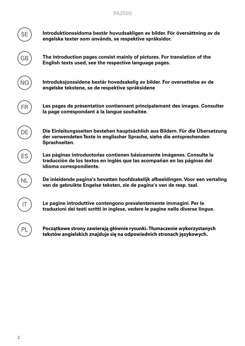
Introduktionssidorna består huvudsakligen av bilder. För översättning av de engelska texter som används, se respektive språksidor.
SE
The introduction pages consist mainly of pictures. For translation of the English texts used, see the respective language pages.
GB
Introduksjonssidene består hovedsakelig av bilder. For oversettelse av de engelske tekstene, se de respektive språksidene
NO
Les pages de présentation contiennent principalement des images. Consulter la page correspondant à la langue souhaitée.
FR
Die Einleitungsseiten bestehen hauptsächlich aus Bildern. Für die Übersetzung der verwendeten Texte in englischer Sprache, siehe die entsprechenden Sprachseiten.
DE
Las páginas introductorias contienen básicamente imágenes. Consulte la traducción de los textos en inglés que las acompañan en las páginas del idioma correspondiente.
ES
De inleidende pagina's bevatten hoofdzakelijk afbeeldingen. Voor een vertaling van de gebruikte Engelse teksten, zie de pagina's van de resp. taal.
NL
Le pagine introduttive contengono prevalentemente immagini. Per le traduzioni dei testi scritti in inglese, vedere le pagine nelle diverse lingue.
IT
Początkowe strony zawierają głównie rysunki. Tłumaczenie wykorzystanych tekstów angielskich znajduje się na odpowiednich stronach językowych.
PL
PA2500
2
PA2500
3
PA2500
ø17,5 ø17,5
ø32,5
ø25,5
ø20,5
ø17,5
Gland
Knock-out
Knock-out
Knock-out
Gland
Fig.1
Fig.2
Gland
345
min 500
min 500 min 500
157
157 157
90,5
10
20
4022
210
165
184
1026 / 1536 / 2026
1050 / 1560 / 2050
Cu ø1553
71 40
345
min 500
min 500 min 500
157
157 157
90,5
10
20
4022
210
165
184
1026 / 1536 / 2026
1050 / 1560 / 2050
Cu ø1553
71 40
2 m
PA2500
4
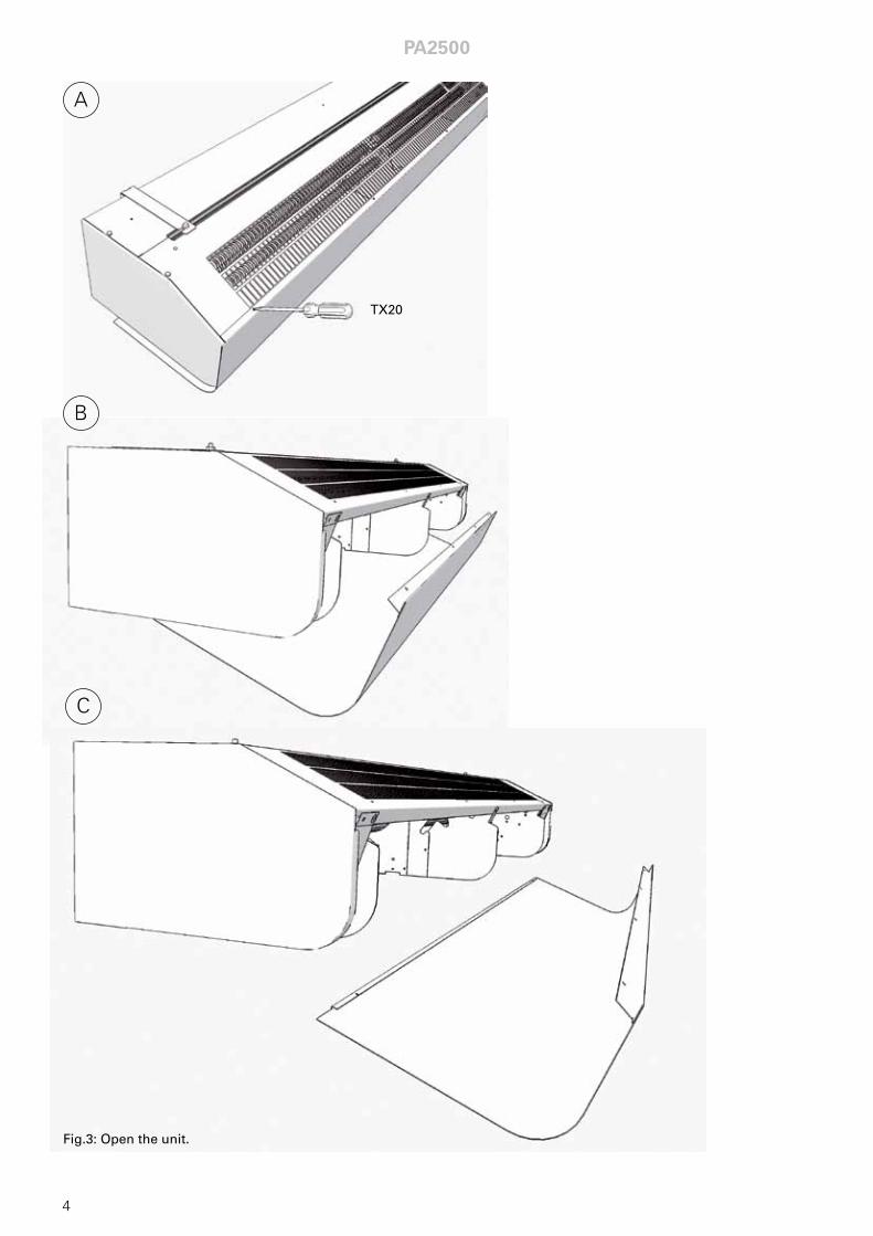
Fig.3: Open the unit.
A
B
C
TX20
PA2500
5
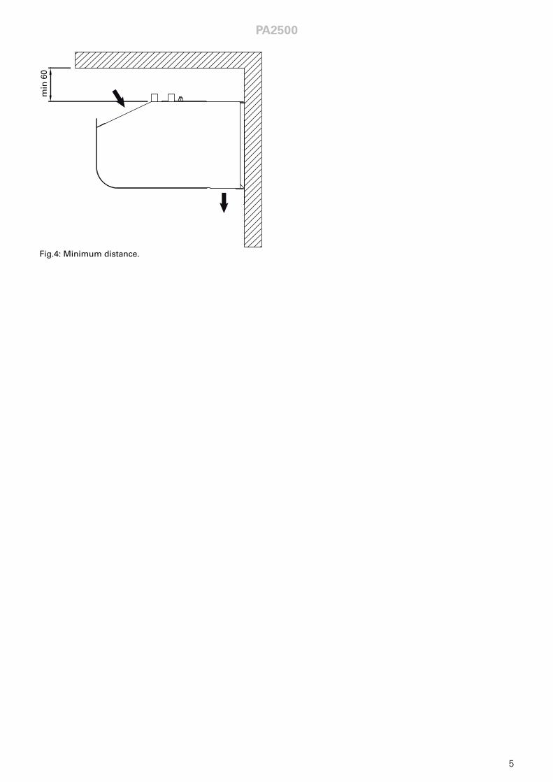
Fig.4: Minimum distance.
min
60
PA2500
6
min 500 mm
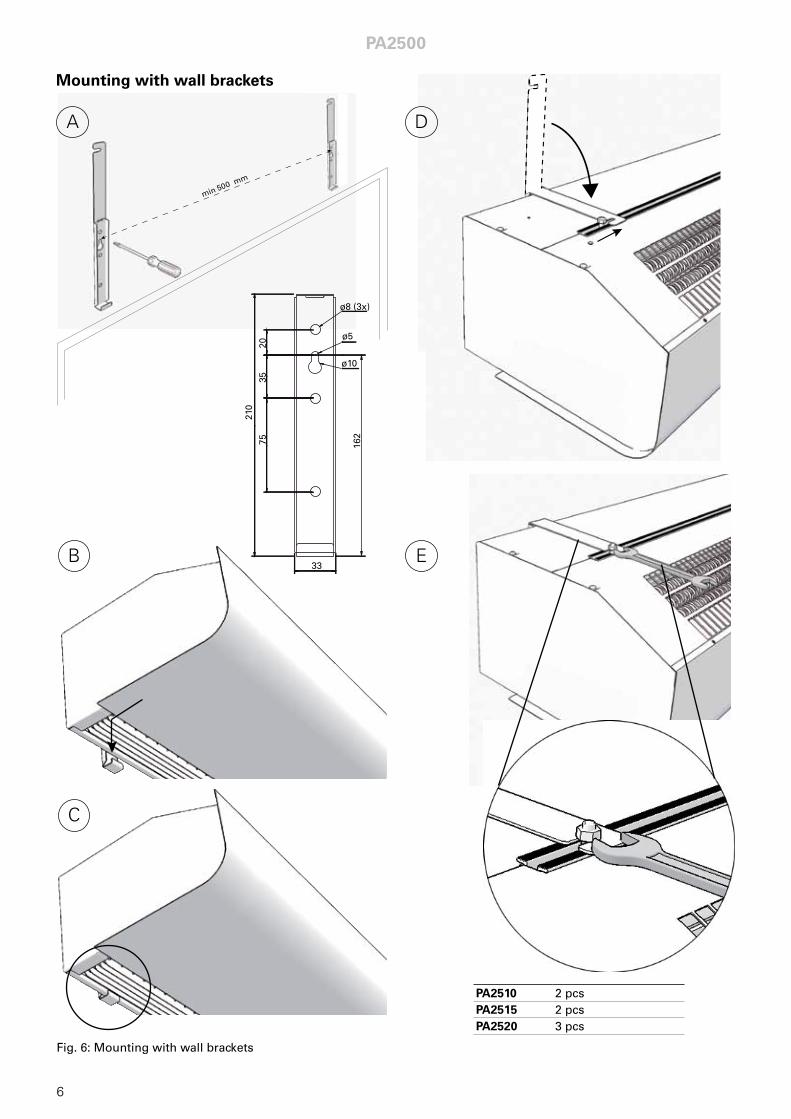
Fig. 6: Mounting with wall brackets
Mounting with wall brackets
A
B
D
PA2510 2 pcsPA2515 2 pcsPA2520 3 pcs
E
C
2035
7521
0
33
ø8 (3x)
ø5
ø1016
2
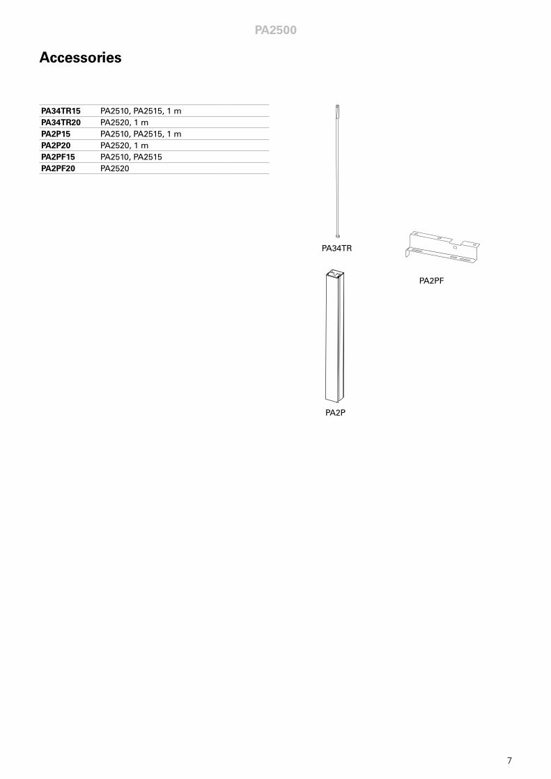
Accessories
PA2500
7
PA34TR
PA2P
PA2PF
PA34TR15 PA2510, PA2515, 1 mPA34TR20 PA2520, 1 mPA2P15 PA2510, PA2515, 1 mPA2P20 PA2520, 1 mPA2PF15 PA2510, PA2515PA2PF20 PA2520
PA2500
8
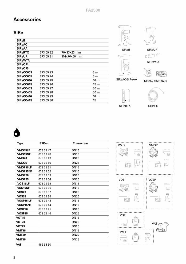
SIReBSIReACSIReAASIReRTX 673 09 22 70x33x23 mmSIReUR 673 09 21 114x70x50 mmSIReWTASIReCJ4SIReCJ6SIReCC603 673 09 23 3 mSIReCC605 673 09 24 5 mSIReCC610 673 09 25 10 mSIReCC615 673 09 26 15 mSIReCC403 673 09 27 30 mSIReCC405 673 09 28 50 mSIReCC410 673 09 29 10 mSIReCC415 673 09 30 15
Type RSK-nr Connection
VMO15LF 673 09 47 DN15VMO15NF 673 09 48 DN15VMO20 673 09 49 DN20
VMO25 673 09 50 DN25
VMOP15LF 673 09 51 DN15VMOP15NF 673 09 52 DN15VMOP20 673 09 53 DN20VMOP25 673 09 54 DN25
VOS15LF 673 09 35 DN15
VOS15NF 673 09 36 DN15
VOS20 673 09 37 DN20
VOS25 673 09 38 DN25
VOSP15 LF 673 09 43 DN15
VOSP15NF 673 09 44 DN15
VOSP20 673 09 45 DN20
VOSP25 673 09 46 DN25
VOT15 DN15
VOT20 DN20
VOT25 DN25
VMT15 DN15
VMT20 DN20
VMT25 DN25
VAT 482 98 30
Accessories
SIReC
SIReB
SIReAC/SIReAA
SIReRTX
SIReUR
SIReWTA
SIReCC
SIReCJ4/SIReCJ6
VOS VOSP
VMO VMOP
VOT
VAT
VMT

PA2510E05/ PA2515E08/ PA2520E10
C2
Ove
r h
eat
cut-
ou
t
°C
C1
L N PE
N N F1 F2 F3H1H2Heating Motor/trafo
ID. pot.
C1
= lo
w p
ow
er
C2
= h
igh
po
wer
L2P
EL1
LN
L3
400V
3N
~
ACTUATOR
SUPPLY
ROOM C1 C 2
Inte
rnal
se
nso
rM
oto
rp
rote
ctio
n
SIR
eB2
Ove
r h
eat
°C
cut-
ou
t
PA25
10E
05PA
2515
E08
PA25
20E
10C
4
C3
C1
= lo
w p
ow
er
C2
= h
igh
po
wer
L2P
EL1
L3400V
3~
M
Blue
BlackBrown
C°
~
Rig
ht
mo
tor
M
Blue
BlackBrown
C°
~
C3
Ru
nC
2Lo
C1
Mid
Left
mo
tor
On
ly 2
m v
ersi
on
C3
Ru
nC
2Lo
C1
Mid
PA2500
9
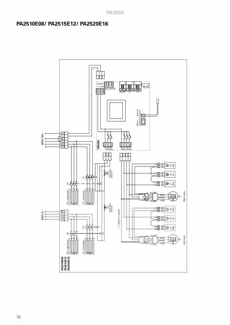
PA2510E08/ PA2515E12/ PA2520E16
C2
Ove
r h
eat
cut-
ou
t
°C
C1
L N PE
N N F1 F2 F3H1H2Heating Motor/trafo
ID. pot.
C1
= lo
w p
ow
er
C2
= h
igh
po
wer
L2P
EL1
LN
L3
400V
3N
~
ACTUATOR
SUPPLY
ROOM C1 C 2
Inte
rnal
se
nso
rM
oto
rp
rote
ctio
n
SIR
eB2
Ove
r h
eat
°C
cut-
ou
t
PA25
10E
08PA
2515
E12
PA25
20E
16C
4
C3
L2P
EL1
L3400V
3~
C1
= lo
w p
ow
er
C2
= h
igh
po
wer
M
Blue
BlackBrown
C°
~
Rig
ht
mo
tor
M
Blue
BlackBrown
C°
~
C3
Ru
nC
2Lo
C1
Mid
Left
mo
tor
On
ly 2
m v
ersi
on
C3
Ru
nC
2Lo
C1
Mid
PA2500
10
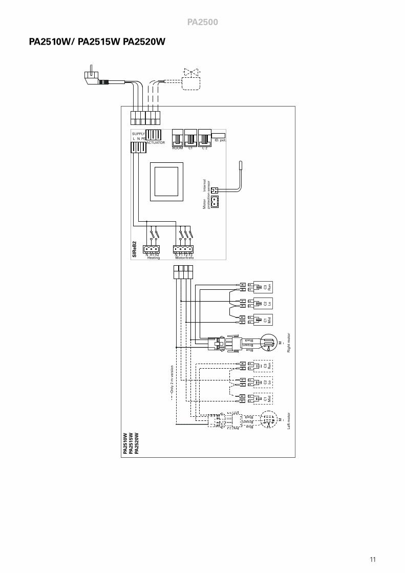
PA2510W/ PA2515W PA2520W
L N PE
N N F1 F2 F3H1H2Heating Motor/trafo
ID. pot.ACTUATOR
SUPPLY
ROOM C1 C 2
Inte
rnal
se
nso
rM
oto
rp
rote
ctio
n
SIR
eB2
PA25
10W
PA25
15W
PA25
20W
M
Blue
BlackBrown
C°
~
Rig
ht
mo
tor
M
Blue
BlackBrown
C°
~
C3
Ru
nC
2Lo
C1
Mid
Left
mo
tor
On
ly 2
m v
ersi
on
C3
Ru
nC
2Lo
C1
Mid
PA2500
11
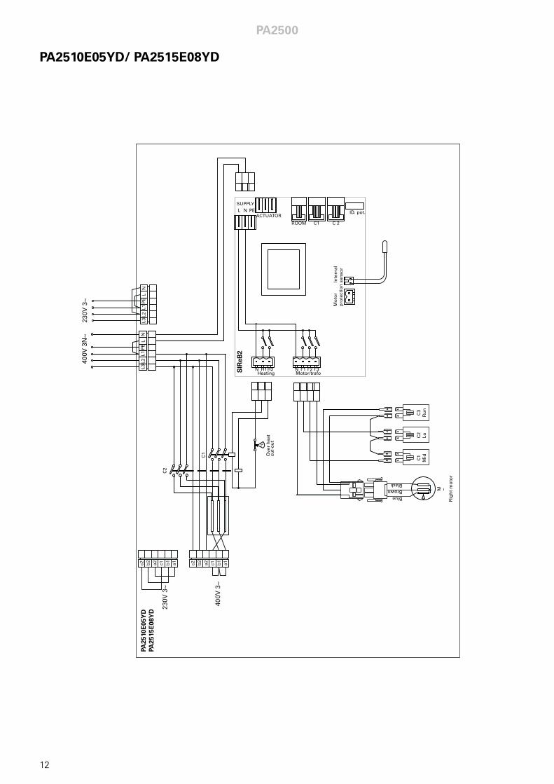
PA2510E05YD/ PA2515E08YD
C2
Ove
r h
eat
cut-
ou
t
°C
C1
L N PE
N N F1 F2 F3H1H2Heating Motor/trafo
ID. pot.
L2P
EL1
LN
L3
400V
3N
~
ACTUATOR
SUPPLY
ROOM C1 C 2
Inte
rnal
se
nso
rM
oto
rp
rote
ctio
n
SIR
eB2
PA25
10E
05Y
DPA
2515
E08
YD
L2P
EL1
LN
L3230V
3~
230V
3~
400V
3~
a1a2b2
c2 c1 b1
a1a2b2
c2 c1 b1
M
Blue
BlackBrown
C°
~
Rig
ht
mo
tor
C3
Ru
nC
2Lo
C1
Mid
PA2500
12
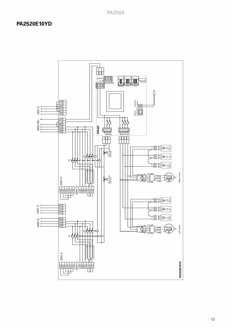
PA2520E10YD
C2
Ove
r h
eat
cut-
ou
t
°C
C1
L N PE
N N F1 F2 F3H1H2Heating Motor/trafo
ID. pot.
L2P
EL1
LN
L3
400V
3N
~
ACTUATOR
SUPPLY
ROOM C1 C 2
Inte
rnal
se
nso
rM
oto
rp
rote
ctio
n
SIR
eB2
Ove
r h
eat
°C
cut-
ou
t
PA25
20E
10Y
D
L2P
EL1
LN
L3230V
3~
230V
3~
400V
3~
a1a2b2
c2 c1 b1
a1a2b2
c2 c1 b1
M
Blue
BlackBrown
C°
~
Rig
ht
mo
tor
C3
Ru
nC
2Lo
C1
Mid
C2
C1
L2P
EL1
L3400V
3~
230V
3~
400V
3~
a1a2b2
c2 c1 b1
a1a2b2
c2 c1 b1
M
Blue
BlackBrown
C°
~
C3
Ru
nC
2Lo
C1
Mid
Left
mo
tor
L2P
EL1
L3230V
3~
PA2500
13
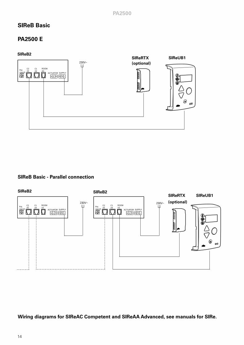
SIReB Basic
PA2500 E
SIReB Basic - Parallel connection
Wiring diagrams for SIReAC Competent and SIReAA Advanced, see manuals for SIRe.
230V~
C2X5
C1X4
ROOMX3Pot.
Unit ID
N L PE N LPE
ACTUATOR SUPPLY
SIReB2SIReUB1SIReRTX
(optional)
230V~ 230V~C2X5
C1X4
ROOMX3Pot.
Unit ID
N L PE N LPE
ACTUATOR SUPPLY
C2X5
C1X4
ROOMX3Pot.
Unit ID
N L PE N LPE
ACTUATOR SUPPLY
SIReB2 SIReB2SIReRTX
(optional)
SIReUB1
PA2500
14
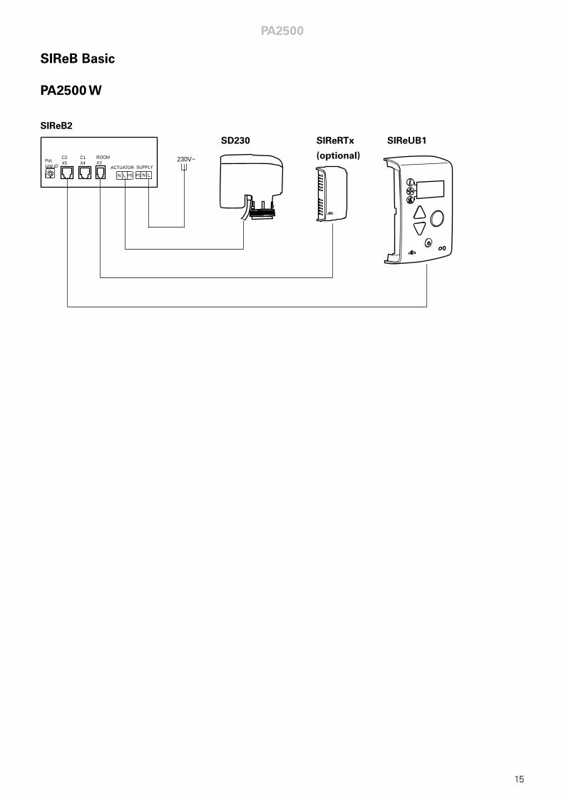
SIReB Basic
PA2500 W
C
C2X5
C1X4
ROOMX3Pot.
Unit ID
N L PE N LPE
ACTUATOR SUPPLY230V~
SIReB2
SD230 SIReRTx
(optional)
SIReUB1
PA2500
15
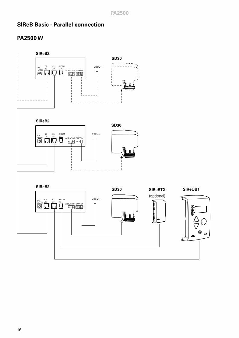
SIReB Basic - Parallel connection
PA2500 W
C2X5
C1X4
ROOMX3Pot.
Unit ID
N L PE N LPE
ACTUATOR SUPPLY
C2X5
C1X4
ROOMX3Pot.
Unit ID
N L PE N LPE
ACTUATOR SUPPLY
C2X5
C1X4
ROOMX3Pot.
Unit ID
N L PE N LPE
ACTUATOR SUPPLY
230V~
230V~
230V~
SIReB2SD30
SIReB2
SIReB2
SD30
SD30 SIReRTX
(optional)
SIReUB1
PA2500
16
PA2500
17
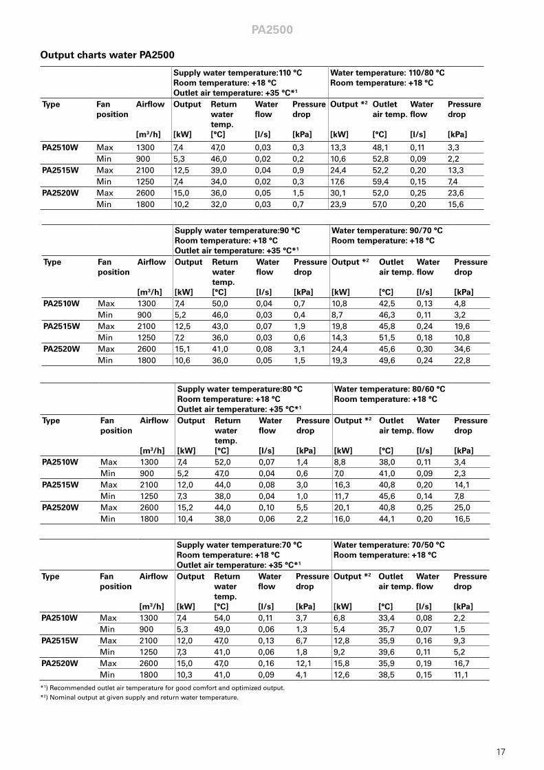
Output charts water PA2500
*1) Recommended outlet air temperature for good comfort and optimized output. *2) Nominal output at given supply and return water temperature.
Supply water temperature:80 °C Room temperature: +18 °C Outlet air temperature: +35 °C*1
Water temperature: 80/60 °C Room temperature: +18 °C
Type Fan position
Airflow [m3/h]
Output [kW]
Return water temp. [°C]
Water flow [l/s]
Pressure drop [kPa]
Output *2 [kW]
Outlet air temp. [°C]
Water flow [l/s]
Pressure drop [kPa]
PA2510W Max 1300 7,4 52,0 0,07 1,4 8,8 38,0 0,11 3,4Min 900 5,2 47,0 0,04 0,6 7,0 41,0 0,09 2,3
PA2515W Max 2100 12,0 44,0 0,08 3,0 16,3 40,8 0,20 14,1Min 1250 7,3 38,0 0,04 1,0 11,7 45,6 0,14 7,8
PA2520W Max 2600 15,2 44,0 0,10 5,5 20,1 40,8 0,25 25,0Min 1800 10,4 38,0 0,06 2,2 16,0 44,1 0,20 16,5
Supply water temperature:90 °C Room temperature: +18 °C Outlet air temperature: +35 °C*1
Water temperature: 90/70 °C Room temperature: +18 °C
Type Fan position
Airflow [m3/h]
Output [kW]
Return water temp. [°C]
Water flow [l/s]
Pressure drop [kPa]
Output *2 [kW]
Outlet air temp. [°C]
Water flow [l/s]
Pressure drop [kPa]
PA2510W Max 1300 7,4 50,0 0,04 0,7 10,8 42,5 0,13 4,8Min 900 5,2 46,0 0,03 0,4 8,7 46,3 0,11 3,2
PA2515W Max 2100 12,5 43,0 0,07 1,9 19,8 45,8 0,24 19,6Min 1250 7,2 36,0 0,03 0,6 14,3 51,5 0,18 10,8
PA2520W Max 2600 15,1 41,0 0,08 3,1 24,4 45,6 0,30 34,6Min 1800 10,6 36,0 0,05 1,5 19,3 49,6 0,24 22,8
Supply water temperature:110 °C Room temperature: +18 °C Outlet air temperature: +35 °C*1
Water temperature: 110/80 °C Room temperature: +18 °C
Type Fan position
Airflow [m3/h]
Output [kW]
Return water temp. [°C]
Water flow [l/s]
Pressure drop [kPa]
Output *2 [kW]
Outlet air temp. [°C]
Water flow [l/s]
Pressure drop [kPa]
PA2510W Max 1300 7,4 47,0 0,03 0,3 13,3 48,1 0,11 3,3Min 900 5,3 46,0 0,02 0,2 10,6 52,8 0,09 2,2
PA2515W Max 2100 12,5 39,0 0,04 0,9 24,4 52,2 0,20 13,3Min 1250 7,4 34,0 0,02 0,3 17,6 59,4 0,15 7,4
PA2520W Max 2600 15,0 36,0 0,05 1,5 30,1 52,0 0,25 23,6Min 1800 10,2 32,0 0,03 0,7 23,9 57,0 0,20 15,6
Supply water temperature:70 °C Room temperature: +18 °C Outlet air temperature: +35 °C*1
Water temperature: 70/50 °C Room temperature: +18 °C
Type Fan position
Airflow [m3/h]
Output [kW]
Return water temp. [°C]
Water flow [l/s]
Pressure drop [kPa]
Output *2 [kW]
Outlet air temp. [°C]
Water flow [l/s]
Pressure drop [kPa]
PA2510W Max 1300 7,4 54,0 0,11 3,7 6,8 33,4 0,08 2,2Min 900 5,3 49,0 0,06 1,3 5,4 35,7 0,07 1,5
PA2515W Max 2100 12,0 47,0 0,13 6,7 12,8 35,9 0,16 9,3Min 1250 7,3 41,0 0,06 1,8 9,2 39,6 0,11 5,2
PA2520W Max 2600 15,0 47,0 0,16 12,1 15,8 35,9 0,19 16,7Min 1800 10,3 41,0 0,09 4,1 12,6 38,5 0,15 11,1
PA2500
18
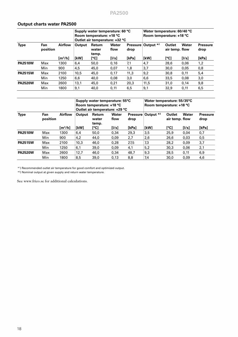
Supply water temperature: 60 °C Room temperature: +18 °C Outlet air temperature: +32 °C
Water temperature: 60/40 °C Room temperature: +18 °C
Type Fan position
Airflow [m3/h]
Output [kW]
Return water temp. [°C]
Water flow [l/s]
Pressure drop [kPa]
Output *2 [kW]
Outlet air temp. [°C]
Water flow [l/s]
Pressure drop [kPa]
PA2510W Max 1300 6,4 50,0 0,16 7,1 4,7 28,6 0,06 1,2Min 900 4,5 45,0 0,07 1,8 3,7 30,0 0,05 0,8
PA2515W Max 2100 10,5 45,0 0,17 11,3 9,2 30,8 0,11 5,4Min 1250 6,6 40,0 0,08 3,0 6,6 33,5 0,08 3,0
PA2520W Max 2600 13,1 45,0 0,21 20,3 11,5 31,0 0,14 9,8Min 1800 9,1 40,0 0,11 6,5 9,1 32,9 0,11 6,5
See www.frico.se for additional calculations.
*1) Recommended outlet air temperature for good comfort and optimized output. *2) Nominal output at given supply and return water temperature.
Supply water temperature: 55°C Room temperature: +18 °C Outlet air temperature: +29 °C
Water temperature: 55/35°C Room temperature: +18 °C
Type Fan position
Airflow [m3/h]
Output [kW]
Return water temp. [°C]
Water flow [l/s]
Pressure drop [kPa]
Output *2 [kW]
Outlet air temp. [°C]
Water flow [l/s]
Pressure drop [kPa]
PA2510W Max 1300 6,4 50,0 0,34 29,3 3,5 25,9 0,04 0,7Min 900 4,2 44,0 0,09 2,7 2,6 26,6 0,03 0,5
PA2515W Max 2100 10,3 46,0 0,28 27,5 7,3 28,2 0,09 3,7Min 1250 6,1 39,0 0,09 4,1 5,2 30,3 0,06 2,1
PA2520W Max 2600 12,7 46,0 0,34 48,7 9,3 28,5 0,11 6,9Min 1800 8,5 39,0 0,13 8,8 7,4 30,0 0,09 4,6
Output charts water PA2500
Type Output*3 [kW]
Airflow [m3/h]
∆t*2
[°C]
Sound level*1 [dB(A)]
Voltage motor [V]
Amperage motor [A]
Voltage heat [V]
Amperage heat [A]
Length [mm]
Weight [kg]
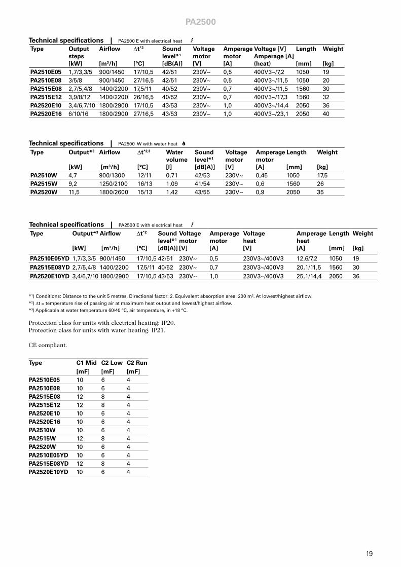
PA2510E05YD 1,7/3,3/5 900/1450 17/10,5 42/51 230V~ 0,5 230V3~/400V3 12,6/7,2 1050 19PA2515E08YD 2,7/5,4/8 1400/2200 17,5/11 40/52 230V~ 0,7 230V3~/400V3 20,1/11,5 1560 30PA2520E10YD 3,4/6,7/10 1800/2900 17/10,5 43/53 230V~ 1,0 230V3~/400V3 25,1/14,4 2050 36
PA2500
19
Type Output steps [kW]
Airflow [m3/h]
∆t*2
[°C]
Sound level*1 [dB(A)]
Voltage motor [V]
Amperage motor [A]
Voltage [V] Amperage [A] (heat)
Length [mm]
Weight [kg]
PA2510E05 1,7/3,3/5 900/1450 17/10,5 42/51 230V~ 0,5 400V3~/7,2 1050 19PA2510E08 3/5/8 900/1450 27/16,5 42/51 230V~ 0,5 400V3~/11,5 1050 20PA2515E08 2,7/5,4/8 1400/2200 17,5/11 40/52 230V~ 0,7 400V3~/11,5 1560 30PA2515E12 3,9/8/12 1400/2200 26/16,5 40/52 230V~ 0,7 400V3~/17,3 1560 32PA2520E10 3,4/6,7/10 1800/2900 17/10,5 43/53 230V~ 1,0 400V3~/14,4 2050 36PA2520E16 6/10/16 1800/2900 27/16,5 43/53 230V~ 1,0 400V3~/23,1 2050 40
Type Output*3 [kW]
Airflow [m3/h]
∆t*2,3
[°C]
Water volume [l]
Sound level*1 [dB(A)]
Voltage motor [V]
Amperage motor [A]
Length [mm]
Weight [kg]
PA2510W 4,7 900/1300 12/11 0,71 42/53 230V~ 0,45 1050 17,5PA2515W 9,2 1250/2100 16/13 1,09 41/54 230V~ 0,6 1560 26PA2520W 11,5 1800/2600 15/13 1,42 43/55 230V~ 0,9 2050 35
Technical specifications | PA2500 E with electrical heat 3
Technical specifications | PA2500 W with water heat 2
Protection class for units with electrical heating: IP20. Protection class for units with water heating: IP21. CE compliant.
*1) Conditions: Distance to the unit 5 metres. Directional factor: 2. Equivalent absorption area: 200 m². At lowest/highest airflow.*2) ∆t = temperature rise of passing air at maximum heat output and lowest/highest airflow.*3) Applicable at water temperature 60/40 °C, air temperature, in +18 °C.
Technical specifications | PA2500 E with electrical heat 3
Type C1 Mid [mF]
C2 Low [mF]
C2 Run [mF]
PA2510E05 10 6 4PA2510E08 10 6 4PA2515E08 12 8 4PA2515E12 12 8 4PA2520E10 10 6 4PA2520E16 10 6 4PA2510W 10 6 4PA2515W 12 8 4PA2520W 10 6 4PA2510E05YD 10 6 4PA2515E08YD 12 8 4PA2520E10YD 10 6 4
PA2500 GB
25
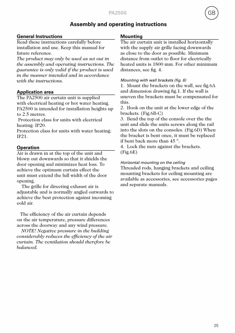
MountingThe air curtain unit is installed horizontally with the supply air grille facing downwards as close to the door as possible. Minimum distance from outlet to floor for electrically heated units is 1800 mm. For other minimum distances, see fig. 4. Mounting with wall brackets (fig. 6)1. Mount the brackets on the wall, see fig.6A and dimension drawing fig.1. If the wall is uneven the brackets must be compensated for this.2. Hook on the unit at the lower edge of the brackets. (Fig.6B-C)3. Bend the top of the console over the the unit and slide the units screws along the rail into the slots on the consoles. (Fig.6D) When the bracket is bent once, it must be replaced if bent back more than 45 °.4. Lock the nuts against the brackets. (Fig.6E) Horizontal mounting on the ceiling Threaded rods, hanging brackets and ceiling mounting brackets for ceiling mounting are available as accessories, see accessories pages and separate manuals.
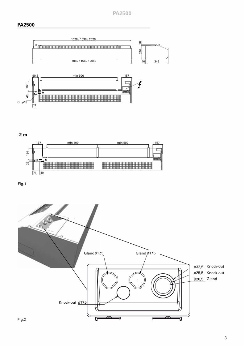
General InstructionsRead these instructions carefully before installation and use. Keep this manual for future reference.The product may only be used as set out in the assembly and operating instructions. The guarantee is only valid if the product is used in the manner intended and in accordance with the instructions. Application areaThe PA2500 air curtain unit is supplied with electrical heating or hot water heating. PA2500 is intended for installation heights up to 2.5 metres. Protection class for units with electrical heating: IP20. Protection class for units with water heating: IP21. OperationAir is drawn in at the top of the unit and blown out downwards so that it shields the door opening and minimizes heat loss. To achieve the optimum curtain effect the unit must extend the full width of the door opening.
The grille for directing exhaust air is adjustable and is normally angled outwards to achieve the best protection against incoming cold air.
The efficiency of the air curtain depends
on the air temperature, pressure differences across the doorway and any wind pressure.
NOTE! Negative pressure in the building considerably reduces the efficiency of the air curtain. The ventilation should therefore be balanced.
Assembly and operating instructions
PA2500GB
26
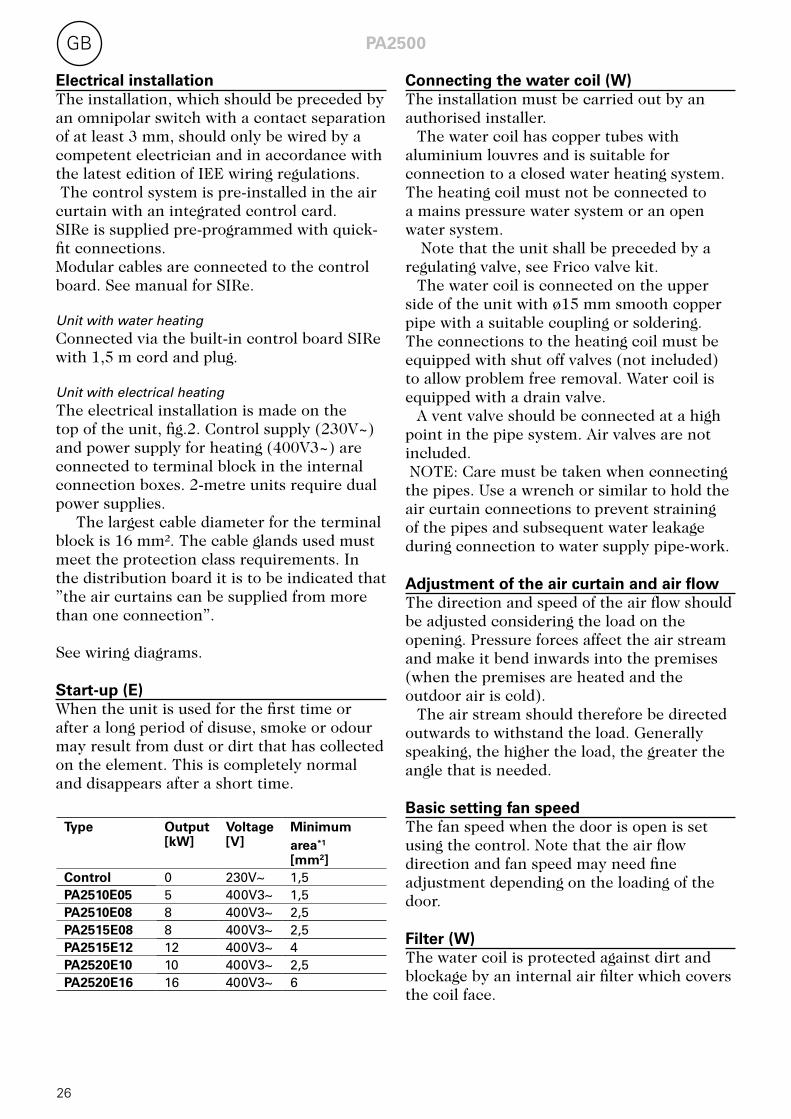
Electrical installationThe installation, which should be preceded by an omnipolar switch with a contact separation of at least 3 mm, should only be wired by a competent electrician and in accordance with the latest edition of IEE wiring regulations. The control system is pre-installed in the air curtain with an integrated control card.SIRe is supplied pre-programmed with quick-fit connections. Modular cables are connected to the control board. See manual for SIRe. Unit with water heatingConnected via the built-in control board SIRe with 1,5 m cord and plug. Unit with electrical heatingThe electrical installation is made on the top of the unit, fig.2. Control supply (230V~) and power supply for heating (400V3~) are connected to terminal block in the internal connection boxes. 2-metre units require dual power supplies.
The largest cable diameter for the terminal block is 16 mm². The cable glands used must meet the protection class requirements. In the distribution board it is to be indicated that ”the air curtains can be supplied from more than one connection”.
See wiring diagrams. Start-up (E)When the unit is used for the first time or after a long period of disuse, smoke or odour may result from dust or dirt that has collected on the element. This is completely normal and disappears after a short time.
Connecting the water coil (W)The installation must be carried out by an authorised installer.
The water coil has copper tubes with aluminium louvres and is suitable for connection to a closed water heating system. The heating coil must not be connected to a mains pressure water system or an open water system.
Note that the unit shall be preceded by a regulating valve, see Frico valve kit.
The water coil is connected on the upper side of the unit with ø15 mm smooth copper pipe with a suitable coupling or soldering. The connections to the heating coil must be equipped with shut off valves (not included) to allow problem free removal. Water coil is equipped with a drain valve.
A vent valve should be connected at a high point in the pipe system. Air valves are not included. NOTE: Care must be taken when connecting the pipes. Use a wrench or similar to hold the air curtain connections to prevent straining of the pipes and subsequent water leakage during connection to water supply pipe-work. Adjustment of the air curtain and air flow The direction and speed of the air flow should be adjusted considering the load on the opening. Pressure forces affect the air stream and make it bend inwards into the premises (when the premises are heated and the outdoor air is cold).
The air stream should therefore be directed outwards to withstand the load. Generally speaking, the higher the load, the greater the angle that is needed.
Basic setting fan speed The fan speed when the door is open is set using the control. Note that the air flow direction and fan speed may need fine adjustment depending on the loading of the door. Filter (W)The water coil is protected against dirt and blockage by an internal air filter which covers the coil face.
Type Output [kW]
Voltage [V]
Minimumarea*1 [mm2]
Control 0 230V~ 1,5PA2510E05 5 400V3~ 1,5PA2510E08 8 400V3~ 2,5PA2515E08 8 400V3~ 2,5PA2515E12 12 400V3~ 4PA2520E10 10 400V3~ 2,5PA2520E16 16 400V3~ 6
PA2500 GB
27
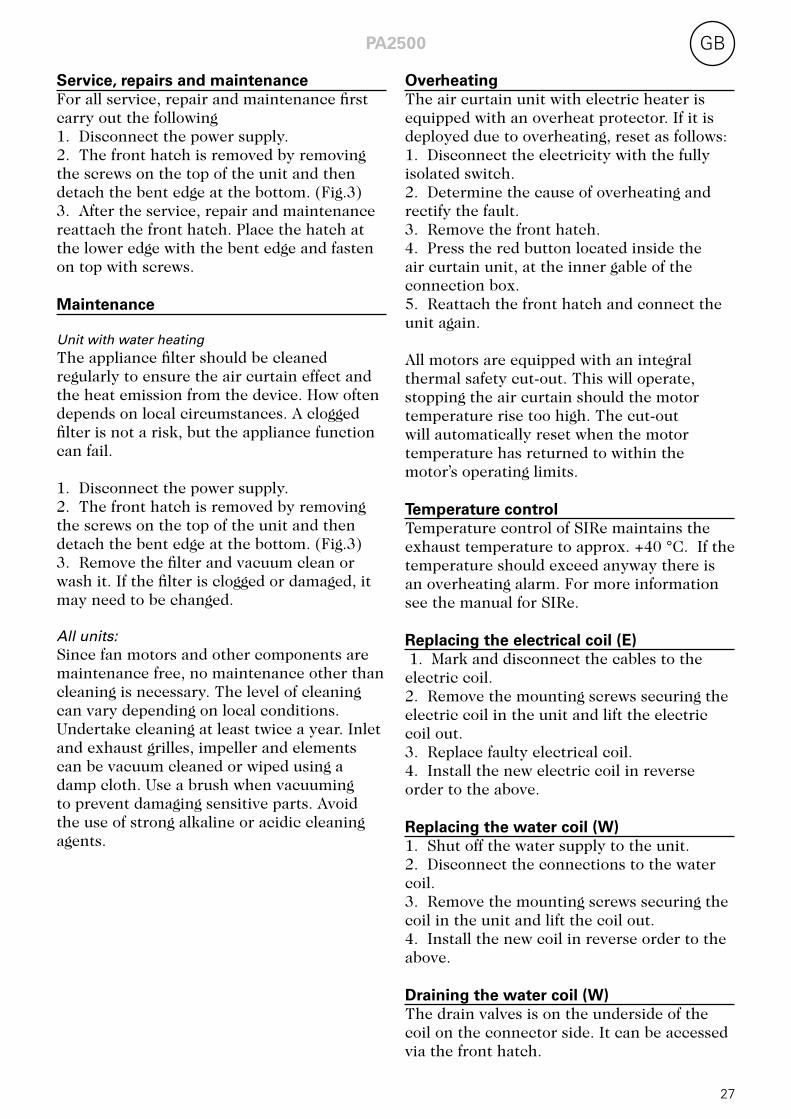
Service, repairs and maintenance For all service, repair and maintenance first carry out the following 1. Disconnect the power supply.2. The front hatch is removed by removing the screws on the top of the unit and then detach the bent edge at the bottom. (Fig.3)3. After the service, repair and maintenance reattach the front hatch. Place the hatch at the lower edge with the bent edge and fasten on top with screws. Maintenance Unit with water heatingThe appliance filter should be cleaned regularly to ensure the air curtain effect and the heat emission from the device. How often depends on local circumstances. A clogged filter is not a risk, but the appliance function can fail. 1. Disconnect the power supply.2. The front hatch is removed by removing the screws on the top of the unit and then detach the bent edge at the bottom. (Fig.3)3. Remove the filter and vacuum clean or wash it. If the filter is clogged or damaged, it may need to be changed. All units: Since fan motors and other components are maintenance free, no maintenance other than cleaning is necessary. The level of cleaning can vary depending on local conditions. Undertake cleaning at least twice a year. Inlet and exhaust grilles, impeller and elements can be vacuum cleaned or wiped using a damp cloth. Use a brush when vacuuming to prevent damaging sensitive parts. Avoid the use of strong alkaline or acidic cleaning agents.
Overheating The air curtain unit with electric heater is equipped with an overheat protector. If it is deployed due to overheating, reset as follows: 1. Disconnect the electricity with the fully isolated switch.2. Determine the cause of overheating and rectify the fault.3. Remove the front hatch.4. Press the red button located inside the air curtain unit, at the inner gable of the connection box.5. Reattach the front hatch and connect the unit again. All motors are equipped with an integral thermal safety cut-out. This will operate, stopping the air curtain should the motor temperature rise too high. The cut-out will automatically reset when the motor temperature has returned to within the motor’s operating limits. Temperature controlTemperature control of SIRe maintains the exhaust temperature to approx. +40 °C. If the temperature should exceed anyway there is an overheating alarm. For more information see the manual for SIRe. Replacing the electrical coil (E) 1. Mark and disconnect the cables to the electric coil.2. Remove the mounting screws securing the electric coil in the unit and lift the electric coil out.3. Replace faulty electrical coil.4. Install the new electric coil in reverse order to the above. Replacing the water coil (W)1. Shut off the water supply to the unit.2. Disconnect the connections to the water coil.3. Remove the mounting screws securing the coil in the unit and lift the coil out.4. Install the new coil in reverse order to the above. Draining the water coil (W)The drain valves is on the underside of the coil on the connector side. It can be accessed via the front hatch.
PA2500GB
28
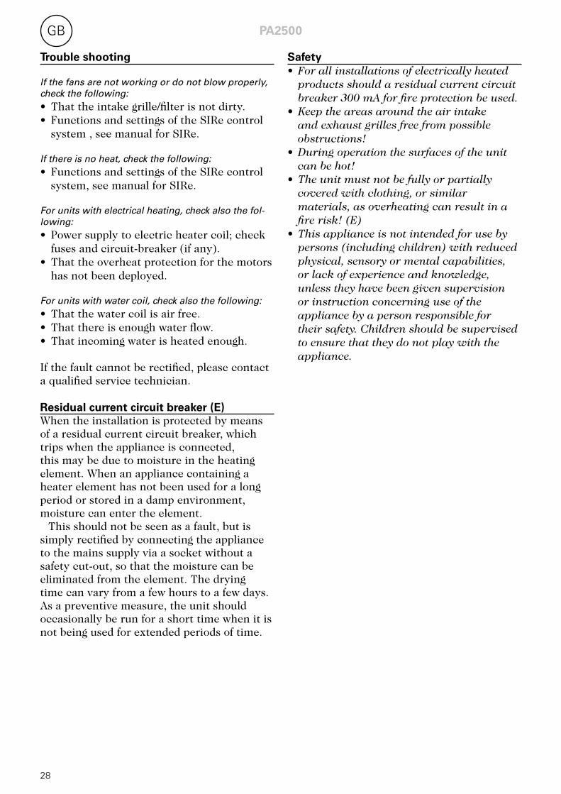
Trouble shooting If the fans are not working or do not blow properly, check the following: • That the intake grille/filter is not dirty.• Functions and settings of the SIRe control
system , see manual for SIRe. If there is no heat, check the following:• Functions and settings of the SIRe control
system, see manual for SIRe. For units with electrical heating, check also the fol-lowing:• Power supply to electric heater coil; check
fuses and circuit-breaker (if any).• That the overheat protection for the motors
has not been deployed. For units with water coil, check also the following:• That the water coil is air free.• That there is enough water flow.• That incoming water is heated enough. If the fault cannot be rectified, please contact a qualified service technician. Residual current circuit breaker (E)When the installation is protected by means of a residual current circuit breaker, which trips when the appliance is connected, this may be due to moisture in the heating element. When an appliance containing a heater element has not been used for a long period or stored in a damp environment, moisture can enter the element.
This should not be seen as a fault, but is simply rectified by connecting the appliance to the mains supply via a socket without a safety cut-out, so that the moisture can be eliminated from the element. The drying time can vary from a few hours to a few days. As a preventive measure, the unit should occasionally be run for a short time when it is not being used for extended periods of time.
Safety• For all installations of electrically heated
products should a residual current circuit breaker 300 mA for fire protection be used.
• Keep the areas around the air intake and exhaust grilles free from possible obstructions!
• During operation the surfaces of the unit can be hot!
• The unit must not be fully or partially covered with clothing, or similar materials, as overheating can result in a fire risk! (E)
• This appliance is not intended for use by persons (including children) with reduced physical, sensory or mental capabilities, or lack of experience and knowledge, unless they have been given supervision or instruction concerning use of the appliance by a person responsible for their safety. Children should be supervised to ensure that they do not play with the appliance.


Art
.no
2088
74, 2
0130
411,
HH
/ LE
Main offi ce Frico AB Tel: +46 31 336 86 00 Box 102 Fax: +46 31 26 28 25 SE-433 22 Partille [email protected] Sweden www.frico.se
For latest updated information and information about your local contact: www.frico.se


![PA3500/4200 - comercialavc.com · Le pagine introduttive contengono prevalentemente immagini. Per le traduzioni dei testi scritti in inglese, ... L1 [mm] L2 [mm] PA4215 1572 1515](https://static.fdocuments.net/doc/165x107/5c6c4e4309d3f28d128c32ab/pa35004200-le-pagine-introduttive-contengono-prevalentemente-immagini-per.jpg)