ORIGINAL INSTRUCTIONS IE101J Installation, … Operation & Maintenance Manual ... from one tank to...
100
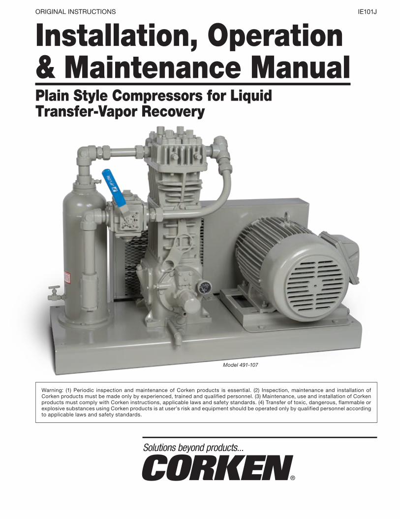
Model 491-107 Installation, Operation & Maintenance Manual Plain Style Compressors for Liquid Transfer-Vapor Recovery Solutions beyond products... ORIGINAL INSTRUCTIONS IE101J Warning: (1) Periodic inspection and maintenance of Corken products is essential. (2) Inspection, maintenance and installation of Corken products must be made only by experienced, trained and qualified personnel. (3) Maintenance, use and installation of Corken products must comply with Corken instructions, applicable laws and safety standards. (4) Transfer of toxic, dangerous, flammable or explosive substances using Corken products is at user’s risk and equipment should be operated only by qualified personnel according to applicable laws and safety standards.
Transcript of ORIGINAL INSTRUCTIONS IE101J Installation, … Operation & Maintenance Manual ... from one tank to...
Model 491-107
Installation, Operation & Maintenance ManualPlain Style Compressors for Liquid Transfer-Vapor Recovery
Solutions beyond products...
ORIGINAL INSTRUCTIONS IE101J
Warning: (1) Periodic inspection and maintenance of Corken products is essential. (2) Inspection, maintenance and installation of Corken products must be made only by experienced, trained and qualified personnel. (3) Maintenance, use and installation of Corken products must comply with Corken instructions, applicable laws and safety standards. (4) Transfer of toxic, dangerous, flammable or explosive substances using Corken products is at user’s risk and equipment should be operated only by qualified personnel according to applicable laws and safety standards.
WarningInstall, use and maintain this equipment according to Corken’s instructions and all applicable federal, state, local laws and codes. Periodic inspection and maintenance is essential.
Corken One Year WarrantyCORKEN, INC. warrants that its products will be free from defects in material and workmanship for a period of one year from date of installation, provided that the warranty shall not extend beyond twenty-four (24) months from the date of shipment from CORKEN. If a warranty dispute occurs, the DISTRIBUTOR may be required to provide CORKEN with proof of date of sale. The minimum requirement would be a copy of the DISTRIBUTOR’S invoice to the customer.
CORKEN products which fail within the warrant period due to defects in material or workmanship will be repaired or replaced at CORKEN’s option, when returned, freight prepaid to CORKEN, INC., 3805 N.W. 36th St., Oklahoma City, Oklahoma 73112.
Parts subject to wear or abuse, such as mechanical seals, blades, piston rings, valves and packing, and other parts showing signs of abuse, neglect or failure to be properly maintained are not covered by this limited warranty. Also, equipment, parts and accessories not manufactured by CORKEN but furnished with CORKEN products are not covered by this limited warranty and the purchaser must look to the original manufacturer’s warranty, if any. This limited warranty is void if the CORKEN product has been altered or repaired without the consent of CORKEN.
All implied warranties, including any implied warranty of merchantability or fitness for a particular purpose, are expressly negated to the extent permitted by law and shall in no event extend beyond the expressed warranty period.
CORKEN DISCLAIMS ANY LIABILITY FOR CONSEQUENTIAL DAMAGES DUE TO BREACH OF ANY WRITTEN OR IMPLIED WARRANTY ON CORKEN PRODUCTS. Transfer of toxic, dangerous, flammable or explosive substances using CORKEN products is at the user’s risk. Experienced, trained personnel in compliance with governmental and industrial safety standards should handle such substances.
Important notes relating to the European Union (EU) Machinery DirectivePumps delivered without electric motors are not considered as machines in the EU Machinery Directive. These pumps will be delivered with a Declaration of Incorporation. The fabricator of the machinery must assure and declare full compliance with this Directive before the machine in which the pump will be incorporated, or of which it is a part, is put into service.
Contacting the FactoryBefore you contact the factory, note the model number and serial number of your pump. The serial number directs us to a file containing all information on material specifications and test data applying to your specific pump. When ordering parts, the Corken service manual or Operations, Installation and Maintenance (IOM) manual should be consulted for the proper part numbers. ALWAYS INCLUDE THE MODEL NUMBER AND SERIAL NUMBER WHEN ORDERING PARTS.
The model and serial numbers are shown on the nameplate of the unit. Record this information for future reference.
Model No.
Serial No.
Date Purchased
Date Installed
Purchased From
Installed By
2
Table of ContentsChapter 1—Introduction . . . . . . . . . . . . . . . . . . . . . . . . . . . . . . . . . . . . . . . . . . . . . . . . . . . . . . . . . . . . . . . . . . . . . . . . 4
1.1 Liquid Transfer By Vapor Differential Pressure . . . . . . . . . . . . . . . . . . . . . . . . . . . . . . . . . . . . . . . . . . . . . . . . . . . 51.2 Residual Vapor Recovery . . . . . . . . . . . . . . . . . . . . . . . . . . . . . . . . . . . . . . . . . . . . . . . . . . . . . . . . . . . . . . . . . . . . 51.3 Compressor Construction Features . . . . . . . . . . . . . . . . . . . . . . . . . . . . . . . . . . . . . . . . . . . . . . . . . . . . . . . . . . . 6
Chapter 2—Installing Your Corken Compressor . . . . . . . . . . . . . . . . . . . . . . . . . . . . . . . . . . . . . . . . . . . . . . . . . . . . 8
2.1 Location . . . . . . . . . . . . . . . . . . . . . . . . . . . . . . . . . . . . . . . . . . . . . . . . . . . . . . . . . . . . . . . . . . . . . . . . . . . . . . . . . 82.2 Foundation . . . . . . . . . . . . . . . . . . . . . . . . . . . . . . . . . . . . . . . . . . . . . . . . . . . . . . . . . . . . . . . . . . . . . . . . . . . . . . . 82.3 Piping . . . . . . . . . . . . . . . . . . . . . . . . . . . . . . . . . . . . . . . . . . . . . . . . . . . . . . . . . . . . . . . . . . . . . . . . . . . . . . . . . . . 82.4 Liquid Traps . . . . . . . . . . . . . . . . . . . . . . . . . . . . . . . . . . . . . . . . . . . . . . . . . . . . . . . . . . . . . . . . . . . . . . . . . . . . . 112.5 Driver Installation / Flywheels . . . . . . . . . . . . . . . . . . . . . . . . . . . . . . . . . . . . . . . . . . . . . . . . . . . . . . . . . . . . . . . 122.6. Crankcase Lubrication . . . . . . . . . . . . . . . . . . . . . . . . . . . . . . . . . . . . . . . . . . . . . . . . . . . . . . . . . . . . . . . . . . . . 122.7 Relief Valves . . . . . . . . . . . . . . . . . . . . . . . . . . . . . . . . . . . . . . . . . . . . . . . . . . . . . . . . . . . . . . . . . . . . . . . . . . . . . 142.8 Truck Mounted Compressors . . . . . . . . . . . . . . . . . . . . . . . . . . . . . . . . . . . . . . . . . . . . . . . . . . . . . . . . . . . . . . . 152.9 Shutdown/Alarm Devices . . . . . . . . . . . . . . . . . . . . . . . . . . . . . . . . . . . . . . . . . . . . . . . . . . . . . . . . . . . . . . . . . . . 15
Chapter 3—Starting Up Your Corken Compressor . . . . . . . . . . . . . . . . . . . . . . . . . . . . . . . . . . . . . . . . . . . . . . . . . 16
3.1 Inspection After Extended Storage . . . . . . . . . . . . . . . . . . . . . . . . . . . . . . . . . . . . . . . . . . . . . . . . . . . . . . . . . . . 163.2 Flywheel and V-belt Alignment . . . . . . . . . . . . . . . . . . . . . . . . . . . . . . . . . . . . . . . . . . . . . . . . . . . . . . . . . . . . . . 163.3 Crankcase Oil Pressure Adjustment . . . . . . . . . . . . . . . . . . . . . . . . . . . . . . . . . . . . . . . . . . . . . . . . . . . . . . . . . . 163.4 Startup Check List . . . . . . . . . . . . . . . . . . . . . . . . . . . . . . . . . . . . . . . . . . . . . . . . . . . . . . . . . . . . . . . . . . . . . . . . 17
Chapter 4—Routine Maintenance Chart . . . . . . . . . . . . . . . . . . . . . . . . . . . . . . . . . . . . . . . . . . . . . . . . . . . . . . . . . 18
Chapter 5—Routine Service and Repair Procedures . . . . . . . . . . . . . . . . . . . . . . . . . . . . . . . . . . . . . . . . . . . . . . . 18
5.1 Valves . . . . . . . . . . . . . . . . . . . . . . . . . . . . . . . . . . . . . . . . . . . . . . . . . . . . . . . . . . . . . . . . . . . . . . . . . . . . . . . . . . 185.2 Heads . . . . . . . . . . . . . . . . . . . . . . . . . . . . . . . . . . . . . . . . . . . . . . . . . . . . . . . . . . . . . . . . . . . . . . . . . . . . . . . . . . 205.3 Piston Rings and Piston Ring Expanders . . . . . . . . . . . . . . . . . . . . . . . . . . . . . . . . . . . . . . . . . . . . . . . . . . . . . . 205.4 Pistons . . . . . . . . . . . . . . . . . . . . . . . . . . . . . . . . . . . . . . . . . . . . . . . . . . . . . . . . . . . . . . . . . . . . . . . . . . . . . . . . . 215.5 Piston Rod Packing Adjustment . . . . . . . . . . . . . . . . . . . . . . . . . . . . . . . . . . . . . . . . . . . . . . . . . . . . . . . . . . . . . 225.6 Cylinder and Packing Replacement . . . . . . . . . . . . . . . . . . . . . . . . . . . . . . . . . . . . . . . . . . . . . . . . . . . . . . . . . . 225.7 Bearing Replacement for Crankcase and Connecting Rod . . . . . . . . . . . . . . . . . . . . . . . . . . . . . . . . . . . . . . . . 25
5.7.1 Wrist Pin Bushing Replacement . . . . . . . . . . . . . . . . . . . . . . . . . . . . . . . . . . . . . . . . . . . . . . . . . . . . . . . . . . 255.7.2 Replacing Connecting Rod Bearings . . . . . . . . . . . . . . . . . . . . . . . . . . . . . . . . . . . . . . . . . . . . . . . . . . . . . . 255.7.3 Replacing Crankcase Roller Bearings . . . . . . . . . . . . . . . . . . . . . . . . . . . . . . . . . . . . . . . . . . . . . . . . . . . . . 25
5.8 Oil Pump Inspection . . . . . . . . . . . . . . . . . . . . . . . . . . . . . . . . . . . . . . . . . . . . . . . . . . . . . . . . . . . . . . . . . . . . . . 26
Chapter 6—Extended Storage Procedures . . . . . . . . . . . . . . . . . . . . . . . . . . . . . . . . . . . . . . . . . . . . . . . . . . . . . . . 27
6.1 Repair Kits . . . . . . . . . . . . . . . . . . . . . . . . . . . . . . . . . . . . . . . . . . . . . . . . . . . . . . . . . . . . . . . . . . . . . . . . . . . . . . 276.2 Gasket Sets . . . . . . . . . . . . . . . . . . . . . . . . . . . . . . . . . . . . . . . . . . . . . . . . . . . . . . . . . . . . . . . . . . . . . . . . . . . . . 28
Appendices
A. Model Number Identification Code and Available Options . . . . . . . . . . . . . . . . . . . . . . . . . . . . . . . . . . . . . . . . . . 30B. Specifications . . . . . . . . . . . . . . . . . . . . . . . . . . . . . . . . . . . . . . . . . . . . . . . . . . . . . . . . . . . . . . . . . . . . . . . . . . . . 32C. Compressor Selection . . . . . . . . . . . . . . . . . . . . . . . . . . . . . . . . . . . . . . . . . . . . . . . . . . . . . . . . . . . . . . . . . . . . . . 38D. Outline Dimensions . . . . . . . . . . . . . . . . . . . . . . . . . . . . . . . . . . . . . . . . . . . . . . . . . . . . . . . . . . . . . . . . . . . . . . . . 42E. Parts Details . . . . . . . . . . . . . . . . . . . . . . . . . . . . . . . . . . . . . . . . . . . . . . . . . . . . . . . . . . . . . . . . . . . . . . . . . . . . . 58
Model 91 and F91 . . . . . . . . . . . . . . . . . . . . . . . . . . . . . . . . . . . . . . . . . . . . . . . . . . . . . . . . . . . . . . . . . . . . . . . . . 58Model 291 and F291 . . . . . . . . . . . . . . . . . . . . . . . . . . . . . . . . . . . . . . . . . . . . . . . . . . . . . . . . . . . . . . . . . . . . . . . 66Model 491 and F491 . . . . . . . . . . . . . . . . . . . . . . . . . . . . . . . . . . . . . . . . . . . . . . . . . . . . . . . . . . . . . . . . . . . . . . . 74Model 691 and F691 . . . . . . . . . . . . . . . . . . . . . . . . . . . . . . . . . . . . . . . . . . . . . . . . . . . . . . . . . . . . . . . . . . . . . . . 82Model D891 and FD891 . . . . . . . . . . . . . . . . . . . . . . . . . . . . . . . . . . . . . . . . . . . . . . . . . . . . . . . . . . . . . . . . . . . . 90
F. Troubleshooting . . . . . . . . . . . . . . . . . . . . . . . . . . . . . . . . . . . . . . . . . . . . . . . . . . . . . . . . . . . . . . . . . . . . . . . . . . . 98
3

Connections:Available in threaded NPT or Class 300 RF flanges.
High-efficiency valves:Valves are quiet and highly durable. Special suction valves tolerating small amounts of condensate are available.
O-ring seals:Easy to install O-ring seals head and cylinder.
Ductile iron construction:Cylinder and head are made of ductile iron for maximum thermal shock endurance.
Self-lubricating PTFE piston rings:State-of-the-art piston ring designs to provide the most cost-effective operation of compressors for non-lube service. The step-cut design provides higher efficiencies during the entire life of the piston ring.
Positively locked piston:Simple piston design allows end clearance to be precisely set to provide maximum efficiency and long life.
Piston rod seals:Seals constructed of PTFE incorporating special fillers to maximize leakage control. Spring loaded seal design self adjusts to compensate for normal wear.
Nitrotec ®1 coated piston rods:Impregnated nitride coating provides superior corrosion and wear resistance.
Cast-iron crosshead:Durable cast-iron crossheads provide superior resistance to corrosion and galling.
Pressure-lubricated crankcase with filter:Self-reversing oil pump ensures proper lubrication regardless of directional rotation to main and connecting rod bearings. Standard 10-micron filter ensures long-lasting bearing life (not available on Model 91).
1 Registered trademark of TTI Group Ltd.
Chapter 1—Introduction
Construction Details—Model F291 Compressor
4
1 .1 Liquid Transfer By Vapor Differential PressureCorken LPG/NH3 compressors are designed to transfer liquefied gases such as butane/propane mixtures (liquefied petroleum gas or LPG) and Anhydrous Ammonia (NH3) from one tank to another. Liquefied gases such as LPG and NH3 are stored in closed containers where both the liquid and vapor phases are present.
Figure 1.1A: Typical nameplate (also serves as the packing adjusting screw cover)
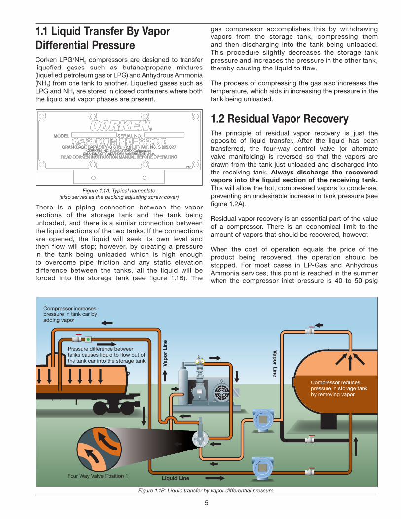
There is a piping connection between the vapor sections of the storage tank and the tank being unloaded, and there is a similar connection between the liquid sections of the two tanks. If the connections are opened, the liquid will seek its own level and then flow will stop; however, by creating a pressure in the tank being unloaded which is high enough to overcome pipe friction and any static elevation difference between the tanks, all the liquid will be forced into the storage tank (see figure 1.1B). The
gas compressor accomplishes this by withdrawing vapors from the storage tank, compressing them and then discharging into the tank being unloaded. This procedure slightly decreases the storage tank pressure and increases the pressure in the other tank, thereby causing the liquid to flow.
The process of compressing the gas also increases the temperature, which aids in increasing the pressure in the tank being unloaded.
1 .2 Residual Vapor RecoveryThe principle of residual vapor recovery is just the opposite of liquid transfer. After the liquid has been transferred, the four-way control valve (or alternate valve manifolding) is reversed so that the vapors are drawn from the tank just unloaded and discharged into the receiving tank. Always discharge the recovered vapors into the liquid section of the receiving tank . This will allow the hot, compressed vapors to condense, preventing an undesirable increase in tank pressure (see figure 1.2A).
Residual vapor recovery is an essential part of the value of a compressor. There is an economical limit to the amount of vapors that should be recovered, however.
When the cost of operation equals the price of the product being recovered, the operation should be stopped. For most cases in LP-Gas and Anhydrous Ammonia services, this point is reached in the summer when the compressor inlet pressure is 40 to 50 psig
Figure 1.1B: Liquid transfer by vapor differential pressure.
Compressor reduces pressure in storage tank by removing vapor
Compressor increases pressure in tank car by adding vapor
Pressure difference between tanks causes liquid to flow out of the tank car into the storage tank
Four Way Valve Position 1
Vapor Line
Vapo
r Lin
e
Liquid Line
5
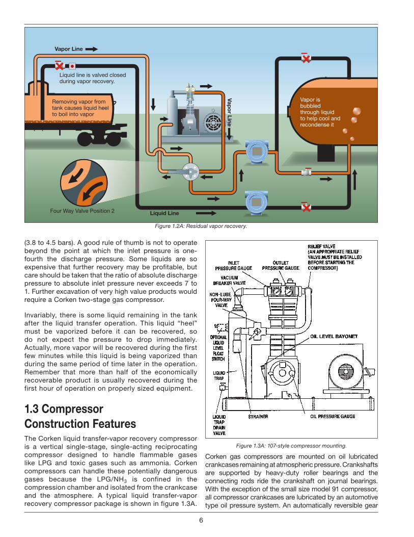
Vapor is bubbled through liquid to help cool and recondense it
Removing vapor from tank causes liquid heel to boil into vapor
Liquid line is valved closed during vapor recovery.
Four Way Valve Position 2
Vapor Line
Vapor Line
Liquid Line
(3.8 to 4.5 bars). A good rule of thumb is not to operate beyond the point at which the inlet pressure is one-fourth the discharge pressure. Some liquids are so expensive that further recovery may be profitable, but care should be taken that the ratio of absolute discharge pressure to absolute inlet pressure never exceeds 7 to 1. Further excavation of very high value products would require a Corken two-stage gas compressor.
Invariably, there is some liquid remaining in the tank after the liquid transfer operation. This liquid “heel” must be vaporized before it can be recovered, so do not expect the pressure to drop immediately. Actually, more vapor will be recovered during the first few minutes while this liquid is being vaporized than during the same period of time later in the operation. Remember that more than half of the economically recoverable product is usually recovered during the first hour of operation on properly sized equipment.
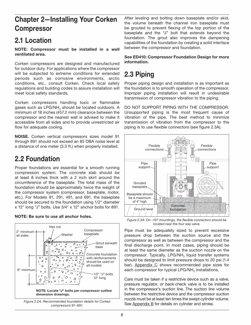
1 .3 Compressor Construction FeaturesThe Corken liquid transfer-vapor recovery compressor is a vertical single-stage, single-acting reciprocating compressor designed to handle flammable gases like LPG and toxic gases such as ammonia. Corken compressors can handle these potentially dangerous gases because the LPG/NH3 is confined in the compression chamber and isolated from the crankcase and the atmosphere. A typical liquid transfer-vapor recovery compressor package is shown in figure 1.3A.
Figure 1.3A: 107-style compressor mounting.
Corken gas compressors are mounted on oil lubricated crankcases remaining at atmospheric pressure. Crankshafts are supported by heavy-duty roller bearings and the connecting rods ride the crankshaft on journal bearings. With the exception of the small size model 91 compressor, all compressor crankcases are lubricated by an automotive type oil pressure system. An automatically reversible gear
Figure 1.2A: Residual vapor recovery.
6

type oil pump circulates oil through passages in the crankshaft and connection rod to lubricate the journal bearings and wrist pins (see figure 1.3B). Sturdy iron crossheads transmit reciprocating motion to the piston.
Corken’s automatically reversible oil pump design allows the machine to function smoothly in either direction of rotation.
Corken compressors use iron pistons locked to the piston rod. The standard piston ring material is a glass-filled PTFE polymer specially formulated for non-lubricated services. Piston ring expanders are placed behind the rings to ensure that the piston rings seal tightly against the cylinder wall.
Figure 1.3B: Pressure lubrication system (not available on Model 91).
Piston rod packing is used to seal the gas in the compression chamber and prevent crankcase oil from entering the compressor cylinder. The packing consists of several PTFE V-rings sandwiched between a male and female packing ring and held in place by a spring (see figure 1.3C).
The typical Corken compressor valve consists of a seat, bumper, one or more spring/s and one or more valve/s discs or plates as shown in figure 1.3D. Special heat-treated alloys are utilized to prolong life of the valve in punishing non-lubricated services. The valve opens whenever the pressure on the seat side exceeds the pressure on the spring side.
Gasket
Adjustingscrew
Relief ball spring
Relief ball
Suction valveseat
Valve plate
SpacersWasher
Spacers
Washer
Valve spring
Suction valvepost
Suction valvebumper
Valve gasket
Gasket
Bolt
Discharge valvebumper
Valve spring
Valve plate
Discharge valveseat
Valve gasket
Suction ValveSpec 3
Discharge ValveAll Specs
Figure 1.3C: Compressor sealing system
Figure 1.3D: Compressor sealing system
7
Chapter 2—Installing Your Corken Compressor
2 .1 LocationNOTE: Compressor must be installed in a well ventilated area .
Corken compressors are designed and manufactured for outdoor duty. For applications where the compressor will be subjected to extreme conditions for extended periods such as corrosive environments, arctic conditions, etc., consult Corken. Check local safety regulations and building codes to assure installation will meet local safety standards.
Corken compressors handling toxic or flammable gases such as LPG/NH3 should be located outdoors. A minimum of 18 inches (457.2 mm) clearance between the compressor and the nearest wall is advised to make it accessible from all sides and to provide unrestricted air flow for adequate cooling.
NOISE . Corken vertical compressors sizes model 91 through 891 should not exceed an 85 DBA noise level at a distance of one meter (3.3 ft.) when properly installed.
2 .2 FoundationProper foundations are essential for a smooth running compression system. The concrete slab should be at least 8 inches thick with a 2 inch skirt around the circumference of the baseplate. The total mass of the foundation should be approximately twice the weight of the compressor system (compressor, baseplate, motor, etc.). For Models 91, 291, 491, and 691, the baseplate should be secured to the foundation using 1/2" diameter x 12" long “J” bolts. Use 3/4" x 12" anchor bolts for 891.
NOTE: Be sure to use all anchor holes .
Hex nut
WasherCompressorbaseplate
NOTE: Locate “J” bolts per compressor outlinedimension drawings .
8" minimum
Grout beneathbase
1/2" “J” bolts12" long
2" minimumall sides
Concrete foundationwith reinforcementsshould be used onall models
Figure 2.2A: Recommended foundation details for Corken compressors 91–691.
After leveling and bolting down baseplate and/or skid, the volume beneath the channel iron baseplate must be grouted to prevent flexing of the top portion of the baseplate and the “J” bolt that extends beyond the foundation. The grout also improves the dampening capabilities of the foundation by creating a solid interface between the compressor and foundation.
See ED410: Compressor Foundation Design for more information .
2 .3 PipingProper piping design and installation is as important as the foundation is to smooth operation of the compressor. Improper piping installation will result in undesirable transmission of compressor vibration to the piping.
DO NOT SUPPORT PIPING WITH THE COMPRESSOR. Unsupported piping is the most frequent cause of vibration of the pipe. The best method to minimize transmission of vibration from the compressor to the piping is to use flexible connectors (see figure 2.3A).
Concretefoundation
Groutedbaseplate
Pipesupport
Pipesupport
Flexibleconnections
Flexibleconnections
Ground level
Baseplate shouldbe a maximum
of 4" high
Figure 2.3A: On –107 mountings, the flexible connectors should be located near the four way valve.
Pipe must be adequately sized to prevent excessive pressure drop between the suction source and the compressor as well as between the compressor and the final discharge point. In most cases, piping should be at least the same diameter as the suction nozzle on the compressor. Typically, LPG/NH3 liquid transfer systems should be designed to limit pressure drops to 20 psi (1.4 bar). Appendix C shows recommended pipe sizes for each compressor for typical LPG/NH3 installations.
Care must be taken if a restrictive device such as a valve, pressure regulator, or back-check valve is to be installed in the compressor’s suction line. The suction line volume between the restrictive device and the compressor suction nozzle must be at least ten times the swept cylinder volume. See Appendix B for details on cylinder and stroke.
8
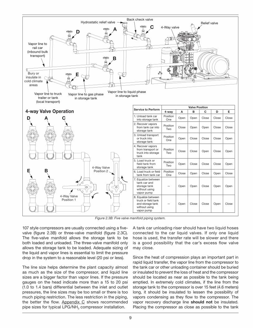
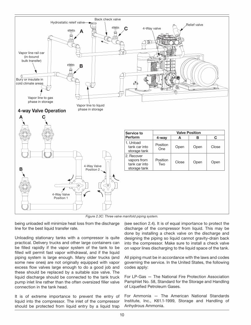
107 style compressors are usually connected using a five-valve (figure 2.3B) or three-valve manifold (figure 2.3C). The five-valve manifold allows the storage tank to be both loaded and unloaded. The three-valve manifold only allows the storage tank to be loaded. Adequate sizing of the liquid and vapor lines is essential to limit the pressure drop in the system to a reasonable level (20 psi or less).
The line size helps determine the plant capacity almost as much as the size of the compressor, and liquid line sizes are a bigger factor than vapor lines. If the pressure gauges on the head indicate more than a 15 to 20 psi (1.0 to 1.4 bars) differential between the inlet and outlet pressures, the line sizes may be too small or there is too much piping restriction. The less restriction in the piping, the better the flow. Appendix C shows recommended pipe sizes for typical LPG/NH3 compressor installation.
A tank car unloading riser should have two liquid hoses connected to the car liquid valves. If only one liquid hose is used, the transfer rate will be slower and there is a good possibility that the car’s excess flow valve may close.
Since the heat of compression plays an important part in rapid liquid transfer, the vapor line from the compressor to the tank car or other unloading container should be buried or insulated to prevent the loss of heat and the compressor should be located as near as possible to the tank being emptied. In extremely cold climates, if the line from the storage tank to the compressor is over 15 feet (4.6 meters) long, it should be insulated to lessen the possibility of vapors condensing as they flow to the compressor. The vapor recovery discharge line should not be insulated. Placing the compressor as close as possible to the tank
Hydrostatic relief valveBack check valve
Relief valve4-Way valveC
Vapor line to liquid phasein storage tank
B
Vapor line to trucktrailer or tank
(local transport)
Vapor line torail car
(inbound bulktransport)
Vapor line to gas phasein storage tank
D
E
A
Bury or insulate in
cold climate areas
4-Way ValvePosition 1
E B
D A C
4-Way ValvePosition 2
Service to PerformValve Position
4-way A B C D E
1. Unload tank car into storage tank
Position One Open Open Close Close Close
2. Recover vapors from tank car into storage tank
Position Two Close Open Open Close Close
3. Unload transport or truck into storage tank
Position One Open Close Close Close Open
4. Recover vapors from transport or truck into storage tank
Position Two Close Close Open Close Open
5. Load truck or field tank from storage tank
Position Two Open Close Close Close Open
6. Load truck or field tank from tank car
Position One Close Open Close Open Close
7. Equalize between tank car and storage tank without using vapor pump
— Open Open Close Open Open
8. Equalize between truck or field tank and storage tank without using vapor pump
— Open Close Close Open Close
4-way Valve Operation
Figure 2.3B: Five valve manifold piping system.
9
being unloaded will minimize heat loss from the discharge line for the best liquid transfer rate.
Unloading stationary tanks with a compressor is quite practical. Delivery trucks and other large containers can be filled rapidly if the vapor system of the tank to be filled will permit fast vapor withdrawal, and if the liquid piping system is large enough. Many older trucks (and some new ones) are not originally equipped with vapor excess flow valves large enough to do a good job and these should be replaced by a suitable size valve. The liquid discharge should be connected to the tank truck pump inlet line rather than the often oversized filler valve connection in the tank head.
It is of extreme importance to prevent the entry of liquid into the compressor. The inlet of the compressor should be protected from liquid entry by a liquid trap
(see section 2.4). It is of equal importance to protect the discharge of the compressor from liquid. This may be done by installing a check valve on the discharge and designing the piping so liquid cannot gravity-drain back into the compressor. Make sure to install a check valve on vapor lines discharging to the liquid space of the tank.
All piping must be in accordance with the laws and codes governing the service. In the United States, the following codes apply:
For LP-Gas — The National Fire Protection Association Pamphlet No. 58, Standard for the Storage and Handling of Liquefied Petroleum Gases.
For Ammonia — The American National Standards Institute, Inc., K61.1-1999, Storage and Handling of Anhydrous Ammonia.
Back check valveHydrostatic releif valve
A
B
C
Vapor line rail car(in-bound
bulk transfer)
Bury or insulate incold climate areas
4-Way valveRelief valve
Vapor line to gasphase in storage
Vapor line to liquidphase in storage
4-Way ValvePosition 1
B
A C
4-Way ValvePosition 2
Service to Perform
Valve Position4-way A B C
1. Unload tank car into storage tank
Position One Open Open Close
2. Recover vapors from tank car into storage tank
Position Two Close Open Open
4-way Valve Operation
Figure 2.3C: Three valve manifold piping system.
10

109 and 107 compressor mountings (see Appendix D for details on standard Corken compressor mountings).
When the compressor will not be under more-or-less constant observation an automatic trap is recommended. The automatic trap replaces the float with electrical float switches. If the liquid level should rise too high, the level switch will open and disconnect the power to the motor starter, stopping the compressor. This design ensures the machine will be protected even when it is not under close observation and is standard in the 109A and 107A mounting configurations.
Corken’s most sophisticated trap provides the most thorough liquid separation. This trap is larger and is ASME code stamped. It contains two level switches, one for alarm and one for shutdown. In some cases the alarm switch is used to activate a dump valve (not included with trap) or sound an alarm for the trap to be manually drained by the operator. This trap also contains a mist pad. A mist pad is a mesh of interwoven wire to catch fine liquid mists. The ASME code trap is standard in the 109B and 107B mounting configurations.
A typical wiring diagram for the liquid level switch is shown in figure 2.4B.
Install, use and maintain this equipment according to Corken instructions and all applicable federal, state, and local laws and previously mentioned codes.
2 .4 Liquid TrapsCompressors are designed to pressurize gas, not to pump liquids. The entry of even a small amount of liquid into the compressor will result in serious damage to the compressor.
On liquefied gas applications, a liquid trap must be used to prevent the entry of liquid into the compressor.
Corken offers three types of liquid traps for removal of liquids in the gas stream (see figure 2.4A). The simplest is a mechanical float trap. As the liquid enters the trap the gas velocity is greatly reduced, which allows the liquid to drop out. If the liquid level rises above the inlet, the float will plug the compressor suction. The compressor creates a vacuum in the inlet piping and continues to operate until the operator manually shuts it down. The trap must be drained and the vacuum-breaker valve opened before restarting the compressor, to allow the float to drop back. This type of trap is only appropriate for use where the operator keeps the compressor under fairly close observation. This trap is provided with the
Figure 2.4A: Liquid traps.
Standard liquid trap with mechanical float assembly and drain valve.
Sizes: • 1-1/4" x 1-1/4" NPT • 1-1/4" x 1-1/2" NPT
Automatic liquid trap, with one NEMA 7 liquid-level switch for compressor shutdown and drain valve.
Sizes: • 1-1/4" x 1-1/4" NPT • 1-1/4" x 1-1/2" NPT
Class 300 RF flange code-stamped automatic liquid trap with two NEMA 7 liquid-level switches for compressor shutdown and alarm. Equipped with relief valve, pressure gauge, demister pad, and drain valve.
Sizes: • 1-1/2" x 1-1/2" NPT • 2" x 2" Class 300 RF flange
Standard Liquid Trap Automatic Liquid Trap ASME Automatic Liquid Trap
11

Typical Float Switch Wiring Diagram
1 = Common, black2 = Normally closed, blue3 = Normally open, red
Figure 2.4B: Typical float switch wiring diagram.
NOTE: The level switch MUST be removed from the trap before grounding any welding devices to the trap or associated piping! Failure to do so will damage the switch contacts .
If your compressor is equipped with a liquid trap of other than Corken manufacture, make sure it is of adequate size to thoroughly remove any liquid present in the suction stream .
2 .5 Driver Installation / FlywheelsCorken vertical compressors may be driven by either electric motors or combustion engines (gasoline, diesel, natural gas, etc.). Corken compressors are usually V-belt driven but they are also suitable for direct drive applications as well. Direct drive applications require an extended crankshaft to allow the attachment of a rigid metal coupling.
Note: Flexible couplings are not suitable for reciprocating compressors. Never operate a reciprocating compressor without a flywheel.
Drivers should be selected so the compressor operates between 350 to 825 RPM. The unit must not be operated without the flywheel or severe torsional imbalances will result that could cause vibration and high horsepower requirement. The flywheel should never be replaced by another pulley unless it has a higher WK 2 value than the flywheel.
A humid climate can cause problems, particularly in explosion proof motors. The normal breathing of the motor, and alternating between being warm when running and being cool when stopped, can cause moist air to be drawn into the motor. This moist air will condense, and may eventually add enough water inside the motor to cause it to fail. To prevent this, make a practice of running the motor at least once a week on a bright, dry day for an hour or so without the V-belts. In this period of time the motor will heat up and vaporize the condensed moisture, driving it from the motor. No motor manufacturer will guarantee their explosion proof or totally enclosed (TEFC) motor against damage from moisture.
For installation with engine drivers, thoroughly review instructions from the engine manufacturer to assure the unit is properly installed.
2 .6 . Crankcase LubricationNon-detergent oil is recommended for Corken vertical compressors. Detergent oils tend to keep wear particles and debris suspended in the oil, whereas non-detergent oils let them settle in the bottom of the crankcase. When non-detergent oils are not available, detergent oils may usually be successfully substituted, although compressors handling ammonia, amine, or imine gases are notable exceptions. These gases react with the detergent and cause the crankcase oil to become corrosive and contaminated. Figures 2.6A and 2.6B show recommended oil viscosities and crankcase capacities.
Acceptable Crankcase Oil Products for Corken Compressors
Constant Weight - Non-Detergent - R&O InhibitedOil product ISO VI SAE Ambient Temp.Exxon®
TERESSTIC100 95 30 65° – 100° F68 95 20+ 45° – 70° F46 95 20 35° – 50° F
Mobil®
RARUS 427 Reciprocating Compressor Oil
100 95 30 65° – 100° F
DTE Oil Heavy Medium 68 95 20+ 45° – 70° FDectol R&O Oil 46 95 20 35° – 50° FConoco®
Dectol R&O Oil100 98 30 65° – 100° F68 97 20+ 45° – 70° F46 99 20 35° – 50° F
Texaco®
Regal R&O Oil100 92 30 65° – 100° F68 97 20+ 45° – 70° F46 102 20 35° – 50° F
Sun®
SunVis 900 Oil100 100 30 65° – 100° F68 100 20+ 45° – 70° F46 100 20 35° – 50° F
Figure 2.6A: Oil selection chart.
Compressor Model
Approximate Quarts
Capacity Liters
91 0.9 0.8
291 1.5 1.4
491 3.0 2.8
691/891 7.0 6.6
Figure 2.6B: Oil capacity chart.
Synthetic lubricants are generally not necessary. Please consult your lubricate supplier if you are considering the use of synthetic oil. To add oil, remove the name plate and pour through the opening.
General Notes on Crankcase OilCorken gas compressors are used for a wide variety of gases in a multitude of operating conditions. They are used in all areas of the world from hot dusty deserts, to humid coastal areas, to cold arctic climates. No single crankcase oil or maintenance schedule is right for every compressor installation. Availability of brands and grades
12

of oil varies from one location to another. These factors can make it challenging for a Corken compressor user to select a suitable crankcase oil.
It is safe to say that purchasing a quality crankcase oil, and changing it regularly, is significantly less costly than the repair bill and downtime associated with a lubrication failure in any gas compressor. Given the relatively small volume of oil used in the crankcase of a Corken compressor, and the critical nature of the services where these compressors are typically used, selecting the appropriate high-quality oil is the most economical choice. It will help ensure the dependability and longevity of the compressor.
Oils to AvoidSelecting a crankcase oil based on low price or easy availability is seldom the most economic decision. Following are oils to avoid.
• Do not use engine/motor oil with an API Service SA through SH.
• Do not use any oil with a viscosity index below 95.
• Do not use any oil with a pour point less than 15ºF (8ºC) lower than the anticipated minimum ambient temperature (unless a crankcase oil heater is used).
See below for additional detail on each of these parameters.
Industrial OilsCorken recommends using industrial oils (rather than engine oil or “motor oil”). Industrial oils have additives specifically selected and blended for specific purposes. Many are designed specifically for the conditions inherent in compressor crankcases. Such industrial oils are required for Corken compressors operating in continuous duty or heavily loaded applications.
Industrial oils do not receive an API service designation like an engine oil does.
Critical Oil CharacteristicsViscosity
The viscosity of a crankcase oil is a measure of its resistance to flow. Viscosity is the most important physical property of lubricating oil. Oils with higher viscosity (ISO 100 and ISO 150) are thicker and are used for higher ambient temperatures. Oils with lower viscosity (ISO 68, ISO 46, and ISO 32) are thinner and are used at lower ambient temperatures. However, oils with a high viscosity index (see below) can be used at wider ambient temperature range compared to oils with a lower viscosity index.
Viscosity Index
Viscosity Index (VI) is a measure of how much the oil’s viscosity changes as its temperature changes. A low viscosity index is an indication that the viscosity changes more as the temperature changes. A high viscosity reflects a more stable viscosity, and is generally preferred for Corken compressors.
Oil with a low viscosity index tends to thin out as the oil temperature increases. This can cause lubrication failure as well as unstable oil pressure. The minimum Viscosity Index for oils used in Corken compressors is 95 (VI is a unit-less number). This is particularly important when operating at high or low temperature extremes, or at a variety of ambient temperatures (seasonal changes).
Pour Point
The pour point of an oil is the lowest temperature at which the oil flows. At temperatures below the pour point, the oil is very thick and can’t freely flow to the compressor’s bearings and other wear surfaces, or even to the compressor’s oil pump.
In low ambient temperature operation, the oil’s pour point is critical. An oil should have a pour point at least 15ºF (8ºC) below the lowest expected ambient temperature. For example, if the minimum ambient temperature is expected to be 0ºF (-18ºC), the pour point must be no higher than -15ºF (-26ºC).
Do not assume the pour point of an oil is low enough. Consult the oil’s technical data sheet. Many oils have a pour point around 0 to 10ºF (-18 to -12ºC) which is too high for low ambient temperatures. Synthetic oils often have a lower pour point than conventional oils.
Engine Oils (Motor Oils)Engine oils are formulated for use in internal combustion engines and contain additives that specifically counter the contaminants created by the combustion of fuel (soot, CO2, water, etc.). A gas compressor crankcase is a different environment than an engine crankcase. Thus, engine oils are not necessarily the best oils to use in a gas compressor. They are by far the most readily available oils.
If a suitable industrial oil is not available, engine oils can be used in Corken compressors used in intermittent service. Heavily loaded compressors or those in continuous duty service should always use high quality industrial oil. If engine oil is used, it is critical that the engine oil have an adequate API Service Grade.
13
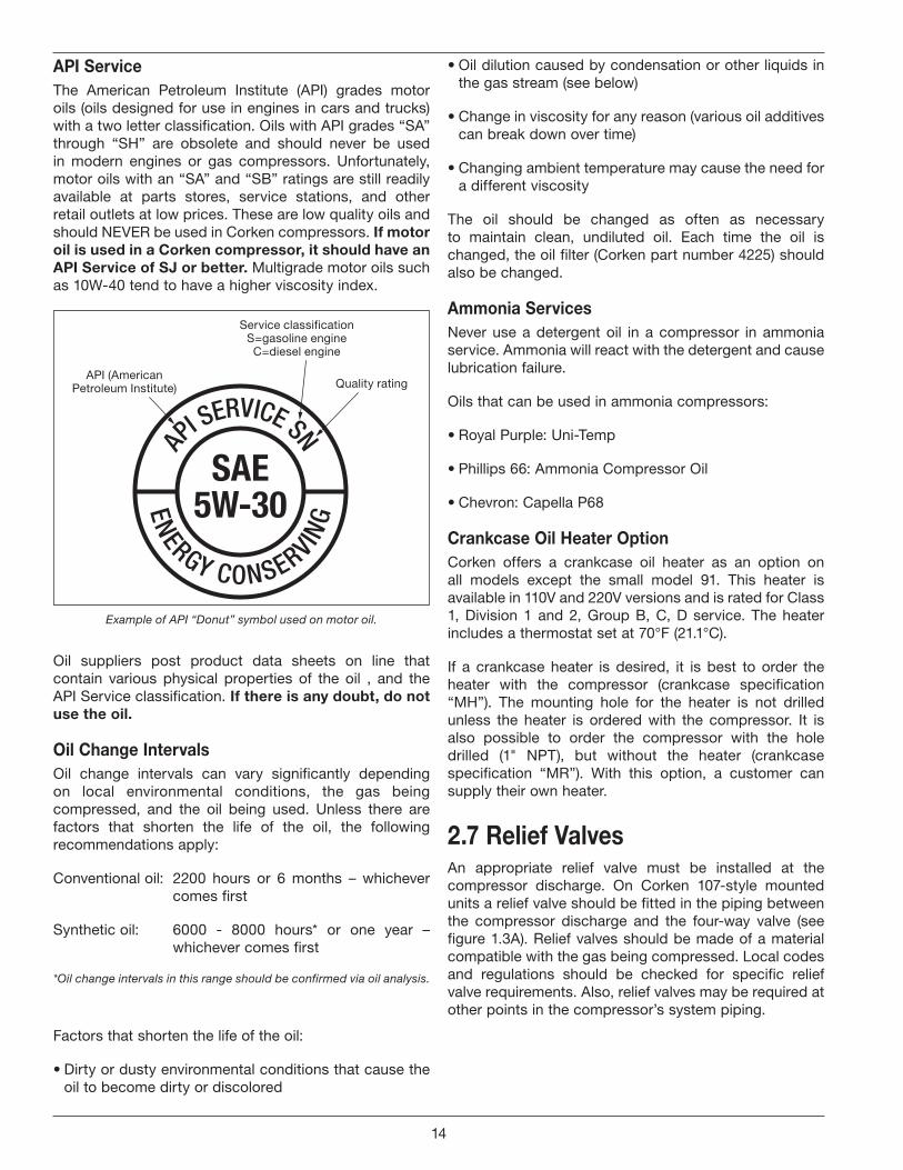
API ServiceThe American Petroleum Institute (API) grades motor oils (oils designed for use in engines in cars and trucks) with a two letter classification. Oils with API grades “SA” through “SH” are obsolete and should never be used in modern engines or gas compressors. Unfortunately, motor oils with an “SA” and “SB” ratings are still readily available at parts stores, service stations, and other retail outlets at low prices. These are low quality oils and should NEVER be used in Corken compressors. If motor oil is used in a Corken compressor, it should have an API Service of SJ or better . Multigrade motor oils such as 10W-40 tend to have a higher viscosity index.
API SERVICE SN
ENERGY CONSERVING
SAE5W-30
API (AmericanPetroleum Institute) Quality rating
Service classificationS=gasoline engineC=diesel engine
Example of API “Donut” symbol used on motor oil.
Oil suppliers post product data sheets on line that contain various physical properties of the oil , and the API Service classification. If there is any doubt, do not use the oil .
Oil Change IntervalsOil change intervals can vary significantly depending on local environmental conditions, the gas being compressed, and the oil being used. Unless there are factors that shorten the life of the oil, the following recommendations apply:
Conventional oil: 2200 hours or 6 months – whichever comes first
Synthetic oil: 6000 - 8000 hours* or one year – whichever comes first
*Oil change intervals in this range should be confirmed via oil analysis.
Factors that shorten the life of the oil:
• Dirty or dusty environmental conditions that cause the oil to become dirty or discolored
• Oil dilution caused by condensation or other liquids in the gas stream (see below)
• Change in viscosity for any reason (various oil additives can break down over time)
• Changing ambient temperature may cause the need for a different viscosity
The oil should be changed as often as necessary to maintain clean, undiluted oil. Each time the oil is changed, the oil filter (Corken part number 4225) should also be changed.
Ammonia ServicesNever use a detergent oil in a compressor in ammonia service. Ammonia will react with the detergent and cause lubrication failure.
Oils that can be used in ammonia compressors:
• Royal Purple: Uni-Temp
• Phillips 66: Ammonia Compressor Oil
• Chevron: Capella P68
Crankcase Oil Heater OptionCorken offers a crankcase oil heater as an option on all models except the small model 91. This heater is available in 110V and 220V versions and is rated for Class 1, Division 1 and 2, Group B, C, D service. The heater includes a thermostat set at 70°F (21.1°C).
If a crankcase heater is desired, it is best to order the heater with the compressor (crankcase specification “MH”). The mounting hole for the heater is not drilled unless the heater is ordered with the compressor. It is also possible to order the compressor with the hole drilled (1" NPT), but without the heater (crankcase specification “MR”). With this option, a customer can supply their own heater.
2 .7 Relief ValvesAn appropriate relief valve must be installed at the compressor discharge. On Corken 107-style mounted units a relief valve should be fitted in the piping between the compressor discharge and the four-way valve (see figure 1.3A). Relief valves should be made of a material compatible with the gas being compressed. Local codes and regulations should be checked for specific relief valve requirements. Also, relief valves may be required at other points in the compressor’s system piping.
14
2 .8 Truck Mounted CompressorsCorken compressors may be mounted on trucks to perform liquid transfer operations as described in section 1.1. The compressor should be mounted so the inspection plate is accessible for packing adjustment. The compressor must be protected against liquid as explained in section 2.4 and a relief valve must be installed in the discharge piping before the first downstream shutoff valve.
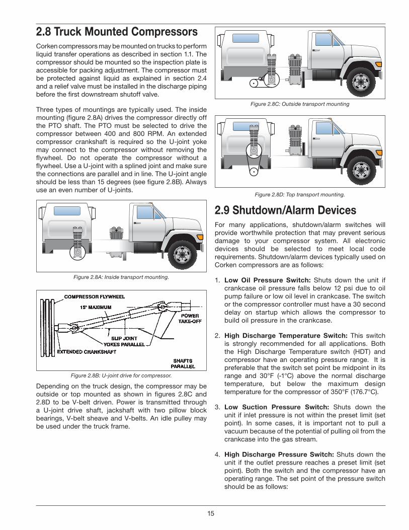
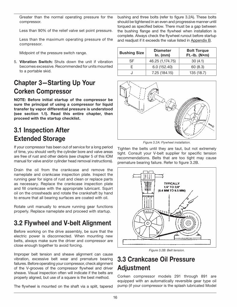
Three types of mountings are typically used. The inside mounting (figure 2.8A) drives the compressor directly off the PTO shaft. The PTO must be selected to drive the compressor between 400 and 800 RPM. An extended compressor crankshaft is required so the U-joint yoke may connect to the compressor without removing the flywheel. Do not operate the compressor without a flywheel. Use a U-joint with a splined joint and make sure the connections are parallel and in line. The U-joint angle should be less than 15 degrees (see figure 2.8B). Always use an even number of U-joints.
Figure 2.8A: Inside transport mounting.
Figure 2.8B: U-joint drive for compressor.
Depending on the truck design, the compressor may be outside or top mounted as shown in figures 2.8C and 2.8D to be V-belt driven. Power is transmitted through a U-joint drive shaft, jackshaft with two pillow block bearings, V-belt sheave and V-belts. An idle pulley may be used under the truck frame.
Figure 2.8C: Outside transport mounting
Figure 2.8D: Top transport mounting.
2 .9 Shutdown/Alarm DevicesFor many applications, shutdown/alarm switches will provide worthwhile protection that may prevent serious damage to your compressor system. All electronic devices should be selected to meet local code requirements. Shutdown/alarm devices typically used on Corken compressors are as follows:
1. Low Oil Pressure Switch: Shuts down the unit if crankcase oil pressure falls below 12 psi due to oil pump failure or low oil level in crankcase. The switch or the compressor controller must have a 30 second delay on startup which allows the compressor to build oil pressure in the crankcase.
2. High Discharge Temperature Switch: This switch is strongly recommended for all applications. Both the High Discharge Temperature switch (HDT) and compressor have an operating pressure range. It is preferable that the switch set point be midpoint in its range and 30°F (-1°C) above the normal discharge temperature, but below the maximum design temperature for the compressor of 350°F (176.7°C).
3. Low Suction Pressure Switch: Shuts down the unit if inlet pressure is not within the preset limit (set point). In some cases, it is important not to pull a vacuum because of the potential of pulling oil from the crankcase into the gas stream.
4. High Discharge Pressure Switch: Shuts down the unit if the outlet pressure reaches a preset limit (set point). Both the switch and the compressor have an operating range. The set point of the pressure switch should be as follows:
15
Greater than the normal operating pressure for the compressor.
Less than 90% of the relief valve set point pressure.
Less than the maximum operating pressure of the compressor.
Midpoint of the pressure switch range.
5. Vibration Switch: Shuts down the unit if vibration becomes excessive. Recommended for units mounted to a portable skid.
Chapter 3—Starting Up Your Corken CompressorNOTE: Before initial startup of the compressor be sure the principal of using a compressor for liquid transfer by vapor differential pressure is understood (see section 1 .1) . Read this entire chapter, then proceed with the startup checklist .
3 .1 Inspection After Extended StorageIf your compressor has been out of service for a long period of time, you should verify the cylinder bore and valve areas are free of rust and other debris (see chapter 5 of this IOM manual for valve and/or cylinder head removal instructions).
Drain the oil from the crankcase and remove the nameplate and crankcase inspection plate. Inspect the running gear for signs of rust and clean or replace parts as necessary. Replace the crankcase inspection plate and fill crankcase with the appropriate lubricant. Squirt oil on the crossheads and rotate the crankshaft by hand to ensure that all bearing surfaces are coated with oil.
Rotate unit manually to ensure running gear functions properly. Replace nameplate and proceed with startup.
3 .2 Flywheel and V-belt AlignmentBefore working on the drive assembly, be sure that the electric power is disconnected. When mounting new belts, always make sure the driver and compressor are close enough together to avoid forcing.
Improper belt tension and sheave alignment can cause vibration, excessive belt wear and premature bearing failures. Before operating your compressor, check alignment of the V-grooves of the compressor flywheel and driver sheave. Visual inspection often will indicate if the belts are properly aligned, but use of a square is the best method.
The flywheel is mounted on the shaft via a split, tapered
bushing and three bolts (refer to figure 3.2A). These bolts should be tightened in an even and progressive manner until torqued as specified below. There must be a gap between the bushing flange and the flywheel when installation is complete. Always check the flywheel runout before startup and readjust if it exceeds the value listed in Appendix B.
Bushing SizeDiameterIn . (mm)
Bolt TorqueFt .-lb . (N•m)
SF 46.25 (1,174.75) 30 (4.1)
E 6.0 (152.40) 60 (8.3)
J 7.25 (184.15) 135 (18.7)
Figure 3.2A: Flywheel installation.
Tighten the belts until they are taut, but not extremely tight. Consult your V-belt supplier for specific tension recommendations. Belts that are too tight may cause premature bearing failure. Refer to figure 3.2B.
Figure 3.2B: Belt tension.
3 .3 Crankcase Oil Pressure AdjustmentCorken compressor models 291 through 891 are equipped with an automatically reversible gear type oil pump (if your compressor is the splash lubricated Model
16

91, proceed to section 3.4). It is essential to ensure the pumping system is primed and the oil pressure is properly adjusted in order to assure smooth operation.
Before starting your compressor, check and fill the crankcase with the proper quantity of lubricating oil. (Refer to section 2.6)
When the compressor is first started, observe the crankcase oil pressure gauge. If the gauge fails to indicate pressure within 30 seconds, stop the machine and loosen the oil filter. Restart the compressor and run until oil comes out and tighten the filter.
The oil pressure should be about 20 psi (1.4 bars) minimum for normal service. If the discharge pressure is above 200 psi (13.8 bars) the oil pressure must be maintained at a minimum of 25 psi (1.7 bars). A spring-loaded relief valve mounted on the bearing housing opposite the flywheel regulates the oil pressure. As shown in figure 3.3A, turn the adjusting screw clockwise to increase the oil pressure and counterclockwise to lower it. Be sure to loosen the adjusting screw locknut before trying to turn the screw and tighten it after making any adjustment.
Oil Pressure Gauge
Oil Level Bayonet
Lock Nut
Oil PressureAdjusting
Screw
+-
Oil Pump Cover
Figure 3.3A: Oil pressure adjustment.
3 .4 Startup Check ListPlease verify all of the items on this list before starting your compressor! Failure to do so may result in a costly (or dangerous) mistake .
Before Starting the Compressor1. Become familiar with the function of all piping
associated with the compressor. Know each line’s use!
2. Verify that actual operating conditions will match the anticipated conditions.
3. Ensure that line pressures are within cylinder pressure ratings.
4. Clean out all piping.
5. Check all mounting shims, cylinder and piping supports to ensure that no undue twisting forces exist on the compressor.
6. Verify that strainer elements are in place and clean.
7. Verify that cylinder bore and valve areas are clean.
8. Check V-belt tension and alignment. Check drive alignment on direct drive units.
9. Rotate unit by hand. Check flywheel for wobble or play.
10. Check crankcase oil level.
11. Drain all liquid traps, separators, etc.
12. Verify proper electrical supply to motor and panel.
13. Check that all gauges are at zero level reading.
14. Test piping system for leaks.
15. Purge unit of air before pressurizing with gas.
16. Carefully check for any loose connections or bolts.
17. Remove all stray objects (rags, tools, etc.) from vicinity of unit.
18. Verify that all valves are open or closed as required.
19. Double-check all of the above.
After Starting Compressor1. Verify and note proper oil pressure. Shut down and
correct any problem immediately.
2. Observe noise and vibration levels. Correct immediately if excessive.
3. Verify proper compressor speed.
4. Examine entire system for gas, oil or water levels.
5. Note rotation direction.
6. Check start-up voltage drop, running amperage and voltage at motor junction box (not at the starter).
7. Test each shutdown device and record set points.
8. Test all relief valves.
9. Check and record all temperatures, pressures and volumes after 30 minutes and 1 hour.
10. After 1 hour running time, tighten all head bolts, valve holddown bolts, and baseplate bolts. See Appendix B for torque values.
17
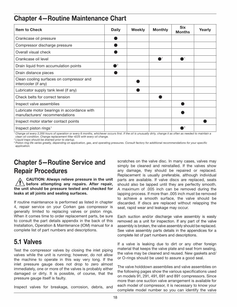
Item to Check Daily Weekly MonthlySix
MonthsYearly
Crankcase oil pressure
Compressor discharge pressure
Overall visual check
Crankcase oil level 1 1
Drain liquid from accumulation points 2
Drain distance pieces
Clean cooling surfaces on compressor and intercooler (if any)
Lubricator supply tank level (if any)
Check belts for correct tension
Inspect valve assemblies
Lubricate motor bearings in accordance with manufacturers’ recommendations
Inspect motor starter contact points
Inspect piston rings 1 3
Chapter 4—Routine Maintenance Chart
1 Change oil every 2,200 hours of operation or every 6 months, whichever occurs first. If the oil is unusually dirty, change it as often as needed to maintain a clean oil condition. Change replacement filter 4225 with every oil change.
2 Liquid traps should be drained prior to startup.3 Piston ring life varies greatly, depending on application, gas, and operating pressures. Consult factory for additional recommendations for your specific
application.
Chapter 5—Routine Service and Repair Procedures
CAUTION: Always relieve pressure in the unit before attempting any repairs . After repair,
the unit should be pressure tested and checked for leaks at all joints and sealing surfaces .
If routine maintenance is performed as listed in chapter 4, repair service on your Corken gas compressor is generally limited to replacing valves or piston rings. When it comes time to order replacement parts, be sure to consult the part details appendix in the back of this Installation, Operation & Maintenance (IOM) manual for a complete list of part numbers and descriptions.
5 .1 ValvesTest the compressor valves by closing the inlet piping valves while the unit is running; however, do not allow the machine to operate in this way very long. If the inlet pressure gauge does not drop to zero almost immediately, one or more of the valves is probably either damaged or dirty. It is possible, of course, that the pressure gauge itself is faulty.
Inspect valves for breakage, corrosion, debris, and
scratches on the valve disc. In many cases, valves may simply be cleaned and reinstalled. If the valves show any damage, they should be repaired or replaced. Replacement is usually preferable, although individual parts are available. If valve discs are replaced, seats should also be lapped until they are perfectly smooth. A maximum of .005 inch can be removed during the lapping process. If more than .005 inch must be removed to achieve a smooth surface, the valve should be discarded. If discs are replaced without relapping the seat, rapid wear and leakage may occur.
Each suction and/or discharge valve assembly is easily removed as a unit for inspection. If any part of the valve assembly is broken, the valve assembly should be replaced. See valve assembly parts details in the appendices for a complete list of part numbers and descriptions.
If a valve is leaking due to dirt or any other foreign material that keeps the valve plate and seat from sealing, the valve may be cleaned and reused. New gaskets and/or O-rings should be used to assure a good seal.
The valve holddown assemblies and valve assemblies on the following pages show the various specifications used on models 91, 291, 491, 691 and 891 compressors. Since more than one suction valve arrangement is available for each model of compressor, it is necessary to know your complete model number so you can identify the valve
18
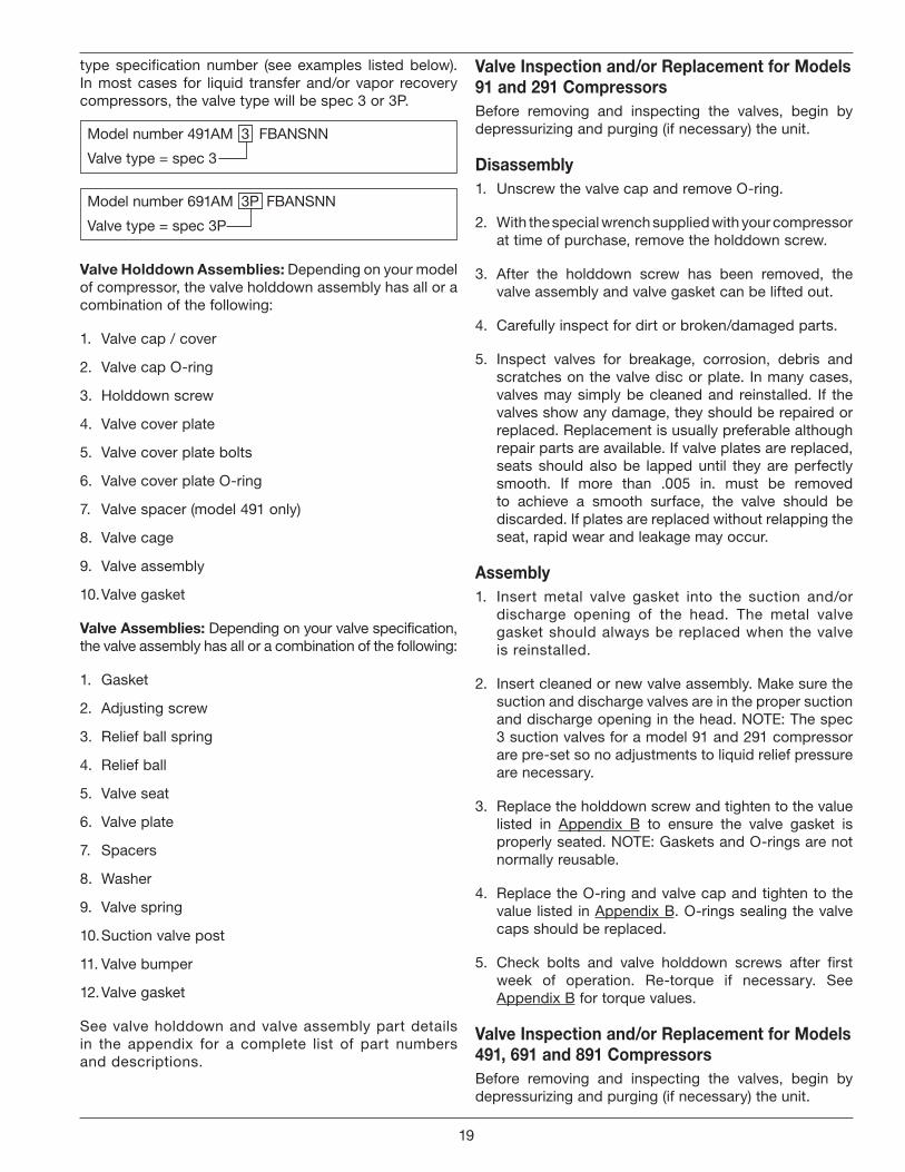
type specification number (see examples listed below). In most cases for liquid transfer and/or vapor recovery compressors, the valve type will be spec 3 or 3P.
Model number 491AM 3 FBANSNN
Valve type = spec 3
Model number 691AM 3P FBANSNN
Valve type = spec 3P
Valve Holddown Assemblies: Depending on your model of compressor, the valve holddown assembly has all or a combination of the following:
1. Valve cap / cover
2. Valve cap O-ring
3. Holddown screw
4. Valve cover plate
5. Valve cover plate bolts
6. Valve cover plate O-ring
7. Valve spacer (model 491 only)
8. Valve cage
9. Valve assembly
10. Valve gasket
Valve Assemblies: Depending on your valve specification, the valve assembly has all or a combination of the following:
1. Gasket
2. Adjusting screw
3. Relief ball spring
4. Relief ball
5. Valve seat
6. Valve plate
7. Spacers
8. Washer
9. Valve spring
10. Suction valve post
11. Valve bumper
12. Valve gasket
See valve holddown and valve assembly part details in the appendix for a complete list of part numbers and descriptions.
Valve Inspection and/or Replacement for Models 91 and 291 CompressorsBefore removing and inspecting the valves, begin by depressurizing and purging (if necessary) the unit.
Disassembly1. Unscrew the valve cap and remove O-ring.
2. With the special wrench supplied with your compressor at time of purchase, remove the holddown screw.
3. After the holddown screw has been removed, the valve assembly and valve gasket can be lifted out.
4. Carefully inspect for dirt or broken/damaged parts.
5. Inspect valves for breakage, corrosion, debris and scratches on the valve disc or plate. In many cases, valves may simply be cleaned and reinstalled. If the valves show any damage, they should be repaired or replaced. Replacement is usually preferable although repair parts are available. If valve plates are replaced, seats should also be lapped until they are perfectly smooth. If more than .005 in. must be removed to achieve a smooth surface, the valve should be discarded. If plates are replaced without relapping the seat, rapid wear and leakage may occur.
Assembly1. Insert metal valve gasket into the suction and/or
discharge opening of the head. The metal valve gasket should always be replaced when the valve is reinstalled.
2. Insert cleaned or new valve assembly. Make sure the suction and discharge valves are in the proper suction and discharge opening in the head. NOTE: The spec 3 suction valves for a model 91 and 291 compressor are pre-set so no adjustments to liquid relief pressure are necessary.
3. Replace the holddown screw and tighten to the value listed in Appendix B to ensure the valve gasket is properly seated. NOTE: Gaskets and O-rings are not normally reusable.
4. Replace the O-ring and valve cap and tighten to the value listed in Appendix B. O-rings sealing the valve caps should be replaced.
5. Check bolts and valve holddown screws after first week of operation. Re-torque if necessary. See Appendix B for torque values.
Valve Inspection and/or Replacement for Models 491, 691 and 891 CompressorsBefore removing and inspecting the valves, begin by depressurizing and purging (if necessary) the unit.
19
Disassembly1. Unscrew the valve cap/nut and remove the O-ring
from the coverplate.
2. Remove the valve cover plate, O-ring and holddown screw by removing each of the four bolts. NOTE: Since the holddown screw has been secured with an impact wrench at the factory, you will probably need to wait to remove the holddown screw until after the cover plate has been removed. At this point in time, the holddown screw can be easily removed from the cover plate. The holddown screw on model 691 and 891 is most easily removed with the special wrench supplied with your compressor at time of purchasing.
3. After the cover plate and O-ring have been removed, the valve spacer (model 491 only), valve cage, valve assembly and valve gasket can be lifted out.
4. Inspect valves for breakage, corrosion, debris, and scratches on the valve plate. In many cases, valves may simply be cleaned and reinstalled. If the valves show any damage, they should be repaired or replaced. Replacement is usually preferable although repair parts are available. If valve plates are replaced, seats should also be lapped until they are perfectly smooth. If more than .005 in. must be removed to achieve a smooth surface, the valve should be discarded. If plates are replaced without relapping the seat, rapid wear and leakage may occur.
Assembly1. Insert metal valve gasket into the suction and/or
discharge opening of the head. The metal valve gasket should always be replaced when the valve is reinstalled.
2. Insert cleaned or new valve assembly. Make sure the suction and discharge valves are in the proper suction and discharge opening in the head.
3. Insert the valve cage and valve spacer (NOTE: spacer applies to model 491 compressor only).
4. Replace the O-ring and valve cover plate. Torque bolts to the value listed in Appendix B. CAUTION: Be sure the holddown screw has been removed.
5. Insert the holddown screw and tighten to the value listed in Appendix B to ensure the valve gasket is properly seated. NOTE: Gaskets and O-rings are not normally reusable.
6. Replace the O-ring (or gasket) and valve cap/nut and tighten to the value listed in Appendix B. O-rings sealing the valve cap should be replaced if they show signs of wear or damage. Valve caps sealed by flat metals gaskets should be reinstalled with new gaskets.
7. NOTE: The Model 491 Spec 3 suction valve has an
adjusting screw to set the liquid relief pressure. To set the liquid relief pressure, the screw bottom must be tightened to 1.8" from the top of the valve body.
8. Check bolts and valve holddown screws after first week of operation. Re-torque if necessary. See Appendix B for torque values.
5 .2 HeadsA compressor head very seldom requires replacement if the compressor is properly maintained. The primary cause of damage to a head is corrosion and the entry of solid debris or liquid into the compression chamber. Improper storage can also result in corrosion damage to the head (for proper storage instructions see chapter 6).
Many compressor repair operations require removal of the head. While the compressor is disassembled, special care should be taken to avoid damage or corrosion to the head. If the compressor is to be left open for more than a few hours, bare metal surfaces should be coated with rust preventative.
When reassembling the compressor, make sure the bolts are retightened as shown in Appendix B.
5 .3 Piston Rings and Piston Ring ExpandersPiston ring life will vary considerably from application to application. Ring life will improve dramatically at lower speeds and temperatures.
1. To replace the piston rings, depressurize the compressor and purge if necessary.
2. Remove the head to gain access to the compressor cylinder.
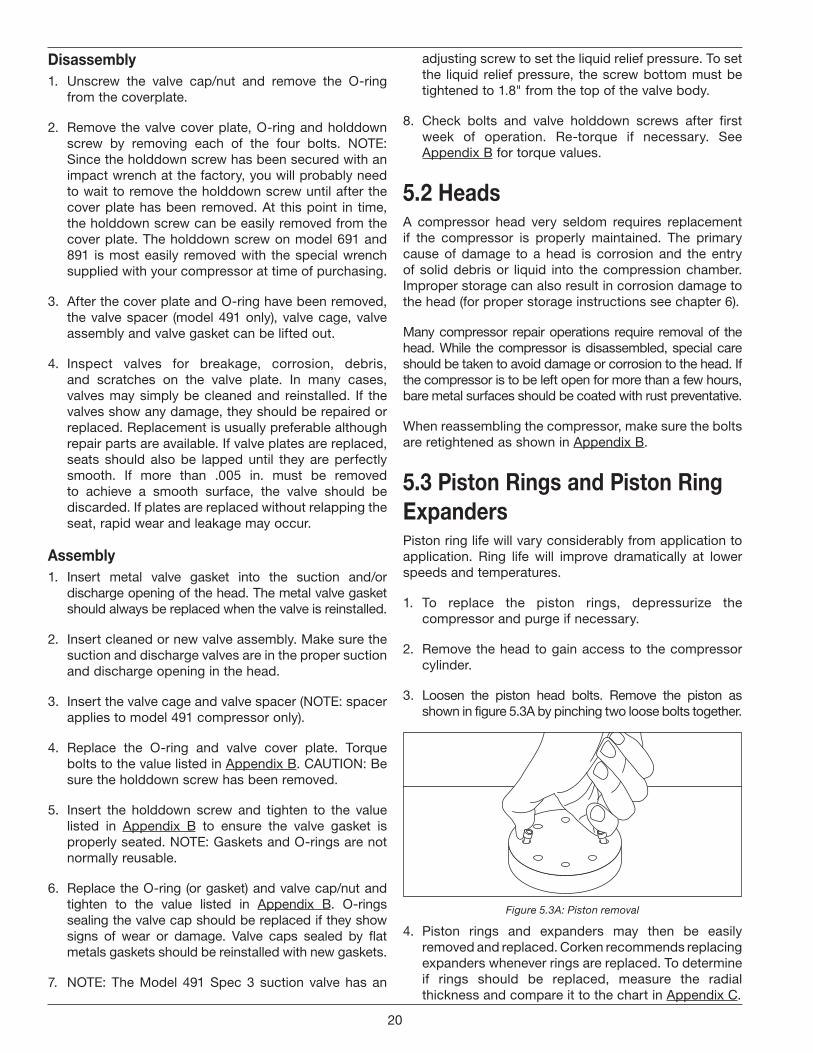
3. Loosen the piston head bolts. Remove the piston as shown in figure 5.3A by pinching two loose bolts together.
Figure 5.3A: Piston removal
4. Piston rings and expanders may then be easily removed and replaced. Corken recommends replacing expanders whenever rings are replaced. To determine if rings should be replaced, measure the radial thickness and compare it to the chart in Appendix C.
20
5 .4 PistonsModels 91, 291, 491, and 6911. To replace the pistons, depressurize the compressor
and purge if necessary.
2. Remove the compressor cylinder and head (see section 5.2).
3. Remove the piston head by loosening and removing the socket head bolts holding the piston head to the piston platform (see figure 5.3A).
4. Next, remove the lock pin with a pair of needle nose pliers. The locknut may then be removed and the piston platform lifted off the end of the piston rod.
5. Check the thrust washer and shims for damage and replace if necessary.
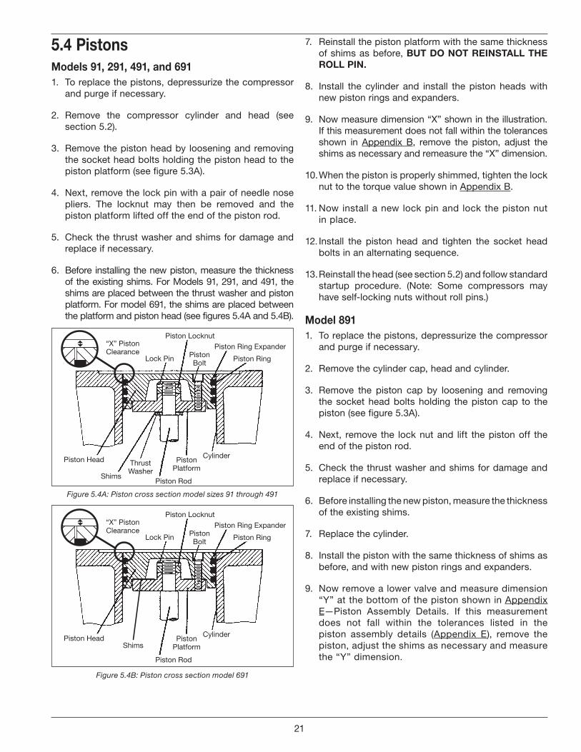
6. Before installing the new piston, measure the thickness of the existing shims. For Models 91, 291, and 491, the shims are placed between the thrust washer and piston platform. For model 691, the shims are placed between the platform and piston head (see figures 5.4A and 5.4B).
“X” Piston Clearance
Piston Head
Shims
Thrust Washer
Lock Pin Piston Bolt
Piston Locknut
Piston Ring Expander
Piston Ring
Piston Platform
Cylinder
Piston Rod
Figure 5.4A: Piston cross section model sizes 91 through 491
“X” Piston Clearance
Piston HeadShims
Lock Pin Piston Bolt
Piston Locknut
Piston Ring Expander
Piston Ring
Piston Platform
Cylinder
Piston Rod
Figure 5.4B: Piston cross section model 691
7. Reinstall the piston platform with the same thickness of shims as before, BUT DO NOT REINSTALL THE ROLL PIN .
8. Install the cylinder and install the piston heads with new piston rings and expanders.
9. Now measure dimension “X” shown in the illustration. If this measurement does not fall within the tolerances shown in Appendix B, remove the piston, adjust the shims as necessary and remeasure the “X” dimension.
10. When the piston is properly shimmed, tighten the lock nut to the torque value shown in Appendix B.
11. Now install a new lock pin and lock the piston nut in place.
12. Install the piston head and tighten the socket head bolts in an alternating sequence.
13. Reinstall the head (see section 5.2) and follow standard startup procedure. (Note: Some compressors may have self-locking nuts without roll pins.)
Model 8911. To replace the pistons, depressurize the compressor
and purge if necessary.
2. Remove the cylinder cap, head and cylinder.
3. Remove the piston cap by loosening and removing the socket head bolts holding the piston cap to the piston (see figure 5.3A).
4. Next, remove the lock nut and lift the piston off the end of the piston rod.
5. Check the thrust washer and shims for damage and replace if necessary.
6. Before installing the new piston, measure the thickness of the existing shims.
7. Replace the cylinder.
8. Install the piston with the same thickness of shims as before, and with new piston rings and expanders.
9. Now remove a lower valve and measure dimension “Y” at the bottom of the piston shown in Appendix E—Piston Assembly Details. If this measurement does not fall within the tolerances listed in the piston assembly details (Appendix E), remove the piston, adjust the shims as necessary and measure the “Y” dimension.
21
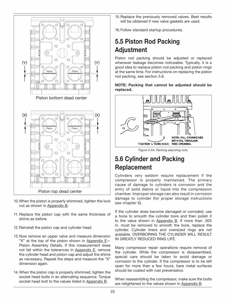
Piston top dead center
Piston Piston
(X) (X)
Piston bottom dead center
Piston Piston
(Y) (Y)
10. When the piston is properly shimmed, tighten the lock nut as shown in Appendix B.
11. Replace the piston cap with the same thickness of shims as before.
12. Reinstall the piston cap and cylinder head.
13. Now remove an upper valve and measure dimension “X” at the top of the piston shown in Appendix E—Piston Assembly Details. If this measurement does not fall within the tolerances in Appendix E, remove the cylinder head and piston cap and adjust the shims as necessary. Repeat the steps and measure the “X” dimension again.
14. When the piston cap is properly shimmed, tighten the socket head bolts in an alternating sequence. Torque socket head bolt to the values listed in Appendix B.
15. Replace the previously removed valves. Best results will be obtained if new valve gaskets are used.
16. Follow standard startup procedures.
5 .5 Piston Rod Packing AdjustmentPiston rod packing should be adjusted or replaced whenever leakage becomes noticeable. Typically, it is a good idea to replace piston rod packing and piston rings at the same time. For instructions on replacing the piston rod packing, see section 5.6.
NOTE: Packing that cannot be adjusted should be replaced .
Figure 5.5A: Packing adjusting nuts.
5 .6 Cylinder and Packing ReplacementCylinders very seldom require replacement if the compressor is properly maintained. The primary cause of damage to cylinders is corrosion and the entry of solid debris or liquid into the compression chamber. Improper storage can also result in corrosion damage to cylinder (for proper storage instructions see chapter 6).
If the cylinder does become damaged or corroded, use a hone to smooth the cylinder bore and then polish it to the value shown in Appendix B. If more than .005 in. must be removed to smooth the bore, replace the cylinder. Cylinder liners and oversized rings are not available. OVERBORING THE CYLINDER WILL RESULT IN GREATLY REDUCED RING LIFE.
Many compressor repair operations require removal of the cylinder. While the compressor is disassembled, special care should be taken to avoid damage or corrosion to the cylinder. If the compressor is to be left open for more than a few hours, bare metal surfaces should be coated with rust preventative.
When reassembling the compressor, make sure the bolts are retightened to the valves shown in Appendix B.
22
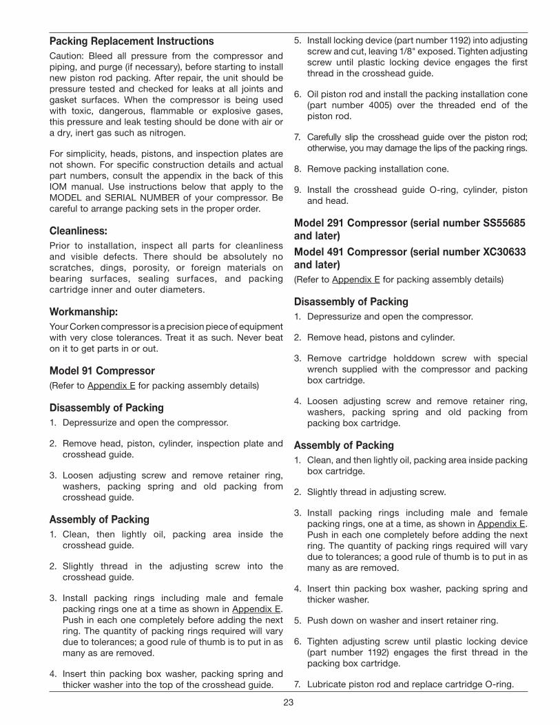
Packing Replacement InstructionsCaution: Bleed all pressure from the compressor and piping, and purge (if necessary), before starting to install new piston rod packing. After repair, the unit should be pressure tested and checked for leaks at all joints and gasket surfaces. When the compressor is being used with toxic, dangerous, flammable or explosive gases, this pressure and leak testing should be done with air or a dry, inert gas such as nitrogen.
For simplicity, heads, pistons, and inspection plates are not shown. For specific construction details and actual part numbers, consult the appendix in the back of this IOM manual. Use instructions below that apply to the MODEL and SERIAL NUMBER of your compressor. Be careful to arrange packing sets in the proper order.
Cleanliness:Prior to installation, inspect all parts for cleanliness and visible defects. There should be absolutely no scratches, dings, porosity, or foreign materials on bearing surfaces, sealing surfaces, and packing cartridge inner and outer diameters.
Workmanship:Your Corken compressor is a precision piece of equipment with very close tolerances. Treat it as such. Never beat on it to get parts in or out.
Model 91 Compressor(Refer to Appendix E for packing assembly details)
Disassembly of Packing1. Depressurize and open the compressor.
2. Remove head, piston, cylinder, inspection plate and crosshead guide.
3. Loosen adjusting screw and remove retainer ring, washers, packing spring and old packing from crosshead guide.
Assembly of Packing1. Clean, then lightly oil, packing area inside the
crosshead guide.
2. Slightly thread in the adjusting screw into the crosshead guide.
3. Install packing rings including male and female packing rings one at a time as shown in Appendix E. Push in each one completely before adding the next ring. The quantity of packing rings required will vary due to tolerances; a good rule of thumb is to put in as many as are removed.
4. Insert thin packing box washer, packing spring and thicker washer into the top of the crosshead guide.
5. Install locking device (part number 1192) into adjusting screw and cut, leaving 1/8" exposed. Tighten adjusting screw until plastic locking device engages the first thread in the crosshead guide.
6. Oil piston rod and install the packing installation cone (part number 4005) over the threaded end of the piston rod.
7. Carefully slip the crosshead guide over the piston rod; otherwise, you may damage the lips of the packing rings.
8. Remove packing installation cone.
9. Install the crosshead guide O-ring, cylinder, piston and head.
Model 291 Compressor (serial number SS55685 and later)Model 491 Compressor (serial number XC30633 and later)(Refer to Appendix E for packing assembly details)
Disassembly of Packing1. Depressurize and open the compressor.
2. Remove head, pistons and cylinder.
3. Remove cartridge holddown screw with special wrench supplied with the compressor and packing box cartridge.
4. Loosen adjusting screw and remove retainer ring, washers, packing spring and old packing from packing box cartridge.
Assembly of Packing1. Clean, and then lightly oil, packing area inside packing
box cartridge.
2. Slightly thread in adjusting screw.
3. Install packing rings including male and female packing rings, one at a time, as shown in Appendix E. Push in each one completely before adding the next ring. The quantity of packing rings required will vary due to tolerances; a good rule of thumb is to put in as many as are removed.
4. Insert thin packing box washer, packing spring and thicker washer.
5. Push down on washer and insert retainer ring.
6. Tighten adjusting screw until plastic locking device (part number 1192) engages the first thread in the packing box cartridge.
7. Lubricate piston rod and replace cartridge O-ring.
23
8. Install packing installation cone part number 4005 over the threaded end of the piston rod.
9. Carefully slip the packing cartridge over the piston rod; otherwise, you may damage the lips of the packing rings.
10. Remove packing installation cone.
11. Install and tighten cartridge holddown screw with special compressor wrench.
12. Install cylinder O-ring, cylinder, pistons, and head.
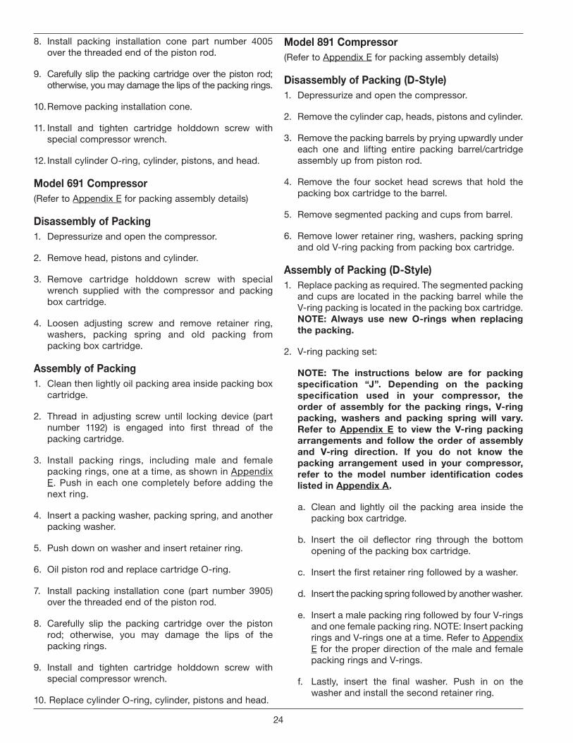
Model 691 Compressor(Refer to Appendix E for packing assembly details)
Disassembly of Packing1. Depressurize and open the compressor.
2. Remove head, pistons and cylinder.
3. Remove cartridge holddown screw with special wrench supplied with the compressor and packing box cartridge.
4. Loosen adjusting screw and remove retainer ring, washers, packing spring and old packing from packing box cartridge.
Assembly of Packing1. Clean then lightly oil packing area inside packing box
cartridge.
2. Thread in adjusting screw until locking device (part number 1192) is engaged into first thread of the packing cartridge.
3. Install packing rings, including male and female packing rings, one at a time, as shown in Appendix E. Push in each one completely before adding the next ring.
4. Insert a packing washer, packing spring, and another packing washer.
5. Push down on washer and insert retainer ring.
6. Oil piston rod and replace cartridge O-ring.
7. Install packing installation cone (part number 3905) over the threaded end of the piston rod.
8. Carefully slip the packing cartridge over the piston rod; otherwise, you may damage the lips of the packing rings.
9. Install and tighten cartridge holddown screw with special compressor wrench.
10. Replace cylinder O-ring, cylinder, pistons and head.
Model 891 Compressor(Refer to Appendix E for packing assembly details)
Disassembly of Packing (D-Style)1. Depressurize and open the compressor.
2. Remove the cylinder cap, heads, pistons and cylinder.
3. Remove the packing barrels by prying upwardly under each one and lifting entire packing barrel/cartridge assembly up from piston rod.
4. Remove the four socket head screws that hold the packing box cartridge to the barrel.
5. Remove segmented packing and cups from barrel.
6. Remove lower retainer ring, washers, packing spring and old V-ring packing from packing box cartridge.
Assembly of Packing (D-Style)1. Replace packing as required. The segmented packing
and cups are located in the packing barrel while the V-ring packing is located in the packing box cartridge. NOTE: Always use new O-rings when replacing the packing .
2. V-ring packing set:
NOTE: The instructions below are for packing specification “J” . Depending on the packing specification used in your compressor, the order of assembly for the packing rings, V-ring packing, washers and packing spring will vary . Refer to Appendix E to view the V-ring packing arrangements and follow the order of assembly and V-ring direction . If you do not know the packing arrangement used in your compressor, refer to the model number identification codes listed in Appendix A .
a. Clean and lightly oil the packing area inside the packing box cartridge.
b. Insert the oil deflector ring through the bottom opening of the packing box cartridge.
c. Insert the first retainer ring followed by a washer.
d. Insert the packing spring followed by another washer.
e. Insert a male packing ring followed by four V-rings and one female packing ring. NOTE: Insert packing rings and V-rings one at a time. Refer to Appendix E for the proper direction of the male and female packing rings and V-rings.
f. Lastly, insert the final washer. Push in on the washer and install the second retainer ring.
24
3. Segmented packing:
NOTE: The instructions below are for packing specification “J” . Depending on the packing specification used in your compressor, the order of assembly for the segmented packing arrangement (radial or tangent) will vary . Refer to Appendix E to view the segmented packing arrangements . If you do not know the packing arrangement used in your compressor, refer to the model number identification codes listed in Appendix A .
a. Clean the segmented packing cups and the area inside the packing barrel.
b. Insert the segmented packing cups, segmented packing pairs and backup rings one at a time in the order shown in Appendix E.
c. Reattach the packing box cartridge to the packing barrel using the four socket head screws.
4. Install three O-rings on the packing barrel and packing box cartridge as shown in the D-Style Crosshead Guide Details in Appendix E.
5. Install packing installation cone (part number 3905) over the threaded end of the piston rod.
6. Carefully install barrel/cartridge assemblies over the piston rods, noting the alignment of the barrels as they sit on the crosshead guide. The valve scallops on the barrels must align properly with the valves in the cylinder.
7. Remove packing installation cone.
8. Replace pistons, cylinders, heads and cylinder cap. See details in Section 5.3 for proper assembly of pistons.
9. Rotate unit by hand to ensure proper assembly.
5 .7 Bearing Replacement for Crankcase and Connecting Rod1. To replace the crankcase roller bearings, wrist pin
bushing and connecting rod bearings, begin by removing the head, cylinder, piston, crosshead guide and crosshead assembly.
2. Drain the crankcase and remove the inspection plate(s).
3. Before disassembly, choose and mark one connecting rod and the corresponding connecting rod cap. DO NOT MIX CONNECTING RODS AND CAPS. Loosen and remove the connecting rod bolts in order to remove the crosshead and connecting rod assembly.
5 .7 .1 Wrist Pin Bushing Replacement1. To replace the wrist pin bushing, remove the retainer
rings that position the wrist pin in the crosshead.
2. Press out the wrist pin so the crosshead and connecting rod may be separated. Inspect the wrist pin for wear and damage and replace if necessary.
3. Press out the old wrist pin bushing and press a new bushing into the connecting rod. DO NOT MACHINE THE O.D. OR I.D. OF THE BUSHING BEFORE PRESSING INTO CONNECTING ROD.
4. Make sure the lubrication hole in the bushing matches the oil passage in the connecting rod. If the holes do not align, press out and insert a new one. Bore the wrist pin bushing I.D. as indicated on the respective connecting rod assembly details. These pages are located in Appendix E. Over boring the bushing can lead to premature failure of the wrist pin bushing.
5. Inspect the oil passage for debris and clean thoroughly before proceeding.
6. Press the wrist pin back into the crosshead and wrist pin and reinstall retainer rings. NOTE: The fit between the wrist pin and bushing is tighter than ordinary lubricated air compressors and combustion engines.
5 .7 .2 Replacing Connecting Rod BearingsConnecting rod bearings are easily replaced by removing the semicircular bearings. Make sure the indentations in the connecting rod bearing and connecting rod line up when installing the new bearings. MAKE SURE THE ARROW AND/OR ALIGNMENT NOTCH ON CONNECTING ROD AND CAP ARE ALIGNED.
Before reinstalling the crosshead/connecting rod assembly, make sure the crankshaft throw and bearing surface are clean and lubricated. Tighten the connecting rod bolts to the torques listed in Appendix B.
5 .7 .3 Replacing Crankcase Roller BearingsTo inspect the roller bearings, remove the flywheel from the crankshaft and then remove the bearing carrier and crankshaft from the crankcase. If corrosion or pitting is present, the roller bearings should be replaced. When replacing roller bearings, always replace the entire bearing, not just the cup or the cone.
1. To replace the bearings, press the cups out of the crankcase and bearing carrier and press the cones off the crankshaft.
2. Press the new bearings into position and reassemble the crankshaft and bearing carrier to the crankcase. When reinstalling the bearing carrier, make sure the oil
25

pump shaft slot is aligned with the pin in the crankshaft. Make sure to install the bearing carrier gasket so the oil passage hole is not blocked (see figure 5.7.3).
3. In order to check the crankshaft endplay, the oil pump must first be removed (see section 5.8).
4. Press the end of crankshaft towards the crankcase; if a clicking noise or motion is detected, the crankshaft has too much endplay. See Appendix B.
5. To reduce endplay, remove the bearing cover and remove a thin shim. Recheck the endplay after replacing the bearing cover.
6. When there is no detectable endplay, the shaft must still be able to rotate freely. If the crankshaft sticks or becomes abnormally warm, then the crankshaft bearings are too tight. If the crankshaft is too tight, add more shims, but make sure not to over shim. (Appendix B lists the proper crankshaft endplay). When the crankshaft can be rotated freely by hand with proper endplay, the rest of the compressor can be reassembled. If the crankshaft roller bearings are too tight or too loose, premature bearing failure will result.
7. Reinstall the flywheel on the crankshaft and check the run out as shown in Appendix B.
5 .8 Oil Pump InspectionIf the compressor operates for a prolonged period with dirty or contaminated crankcase oil, damage to the oil pump may result.
1. To check the oil pump, unbolt the pump cover and remove the oil pump, spring guide, spring, and oil pump shaft adapter as shown in figure 5.8.
2. Inspect the gears in the oil pump for corrosion or pitting and replace if necessary.
3. Inspect the oil pump shaft bushing in the bearing carrier. If the bushing is corroded, pitted or worn, the oil pump shaft bushing should be replaced.
4. Before reassembling the oil pump mechanism, replace the O-rings in the oil pump cover and on the oil pump adapter shaft (see figure 5.8).
5. Rotate the drive pin in the crankshaft to a vertical position for easiest reassembly.
6. Insert the shaft adapter so it engages the drive pin.
7. Next, insert the spring, spring guide, and oil pump assembly. The tang on the oil pump must align with the slot in the shaft adapter.
8. Install the pump cover so the pin on the case is in the opening on the oil pump assembly as shown in figure 5.8. When you are sure the pin is properly aligned, install the cover bolts finger tight.
9. Rotate the crankshaft by hand to ensure smooth operation. Then rotate it in opposite directions, listening for a click, which indicates proper alignment of the oil pump’s pins and slots.
10. Finally, tighten the bolts in an alternating sequence. See section 3.3 for directions on oil pressure adjustment.
Figure 5.7.3: Bearing carrier replacement.
26
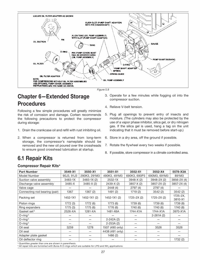
Figure 5.8
Chapter 6—Extended Storage ProceduresFollowing a few simple procedures will greatly minimize the risk of corrosion and damage. Corken recommends the following precautions to protect the compressor during storage:
1. Drain the crankcase oil and refill with rust inhibiting oil.
2. When a compressor is returned from long-term storage, the compressor’s nameplate should be removed and the new oil poured over the crossheads to ensure good crosshead lubrication at startup.
3. Operate for a few minutes while fogging oil into the compressor suction.
4. Relieve V-belt tension.
5. Plug all openings to prevent entry of insects and moisture. (The cylinders may also be protected by the use of a vapor phase inhibitor, silica gel, or dry nitrogen gas. If the silica gel is used, hang a tag on the unit indicating that it must be removed before start-up.)
6. Store in a dry area, off the ground if possible.
7. Rotate the flywheel every two weeks if possible.
8. If possible, store compressor in a climate controlled area.
6 .1 Repair KitsCompressor Repair Kits a
Part Number 3549-X1 3550-X1 3551-X1 3552-X1 3552-X4 5578-X3AModel Number 90J3, 91J3 290K3, 291M3 490K3, 491M3 690K3, 690P3 690M3, 691M3 891M3Suction valve assembly 3483-1X 3483-1X (2) 2532-1X 3948-X (2) 3948-2X (2) 3856-2X (4)Discharge valve assembly 3485-X 3485-X (2) 2439-X (2) 3857-X (2) 3857-2X (2) 3857-2X (4)Valve cage — — 2448 (4) 2797 (4) 2797 (4) —Connecting rod bearing (pair) 1367 1367 (2) 1491 (2) 1719 (2) 3542 (2) 3542 (2)
Packing set 1452-1X1 1452-1X1 (2) 1452-1X1 (2) 1725-2X (2) 1725-2X (2)1725-2X, 3810-X1
Piston rings 1772 (3) 1772 (6) 1773 (6) 1739 (6) 1739 (6) 1739 (8)Ring expanders 1775 (3) 1775 (6) 1776 (6) 1740 (6) 1740 (6) 1740 (8)Gasket set b 2526-XA 1281-XA 1481-X6A 1744-X1A 1744-X1A 3970-X1AO-ring b — — — — 2-261A (2) —O-ring b — — 2-242A (2) — — —O-ring b — — 2-253A (2) — — —Oil seal 3259 1278 1507 (490 only) — 3526 3526Oil seal — — 4438 (491 only) — — —Adapter plate gasket — — 1486 (2) — — —Oil deflector ring — — — — — 1732 (2)
a Quantities greater than one are shown in parenthesis.b All repair kits are furnished with Buna-N O-rings which are suitable for LPG and NH3 applications.
27
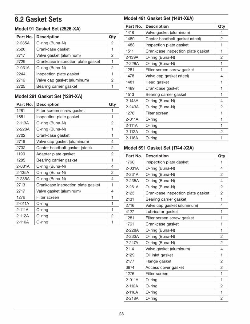
6 .2 Gasket SetsModel 91 Gasket Set (2526-XA)
Part No . Description Qty
2-235A O-ring (Buna-N) 2
2526 Crankcase gasket 1
2717 Valve gasket (aluminum) 2
2729 Crankcase inspection plate gasket 1
2-031A O-ring (Buna-N) 2
2244 Inspection plate gasket 1
2716 Valve cap gasket (aluminum) 2
2725 Bearing carrier gasket 1
Model 291 Gasket Set (1281-XA)
Part No . Description Qty
1281 Filter screen screw gasket 1
1651 Inspection plate gasket 1
2-113A O-ring (Buna-N) 2
2-228A O-ring (Buna-N) 1
2702 Crankcase gasket 1
2716 Valve cap gasket (aluminum) 4
2732 Center headbolt gasket (steel) 2
1190 Adapter plate gasket 2
1285 Bearing carrier gasket 1
2-031A O-ring (Buna-N) 4
2-135A O-ring (Buna-N) 2
2-235A O-ring (Buna-N) 4
2713 Crankcase inspection plate gasket 1
2717 Valve gasket (aluminum) 4
1276 Filter screen 1
2-011A O-ring 1
2-111A O-ring 1
2-112A O-ring 2
2-116A O-ring 1
Model 491 Gasket Set (1481-X6A)
Part No . Description Qty
1418 Valve gasket (aluminum) 4
1480 Center headbolt gasket (steel) 2
1488 Inspection plate gasket 1
1511 Crankcase inspection plate gasket 1
2-139A O-ring (Buna-N) 2
2-228A O-ring (Buna-N) 1
1281 Filter screen screw gasket 1
1478 Valve cap gasket (steel) 4
1481 Head gasket 1
1489 Crankcase gasket 1
1513 Bearing carrier gasket 1
2-143A O-ring (Buna-N) 4
2-243A O-ring (Buna-N) 2
1276 Filter screen 1
2-011A O-ring 1
2-111A O-ring 1
2-112A O-ring 2
2-116A O-ring 1
Model 691 Gasket Set (1744-X3A)
Part No . Description Qty
1760 Inspection plate gasket 1
2-031A O-ring (Buna-N) 4
2-231A O-ring (Buna-N) 2
2-235A O-ring (Buna-N) 4
2-261A O-ring (Buna-N) 2
2123 Crankcase inspection plate gasket 2
2131 Bearing carrier gasket 1
2716 Valve cap gasket (aluminum) 4
4127 Lubricator gasket 1
1281 Filter screen screw gasket 1
1761 Crankcase gasket 1
2-228A O-ring (Buna-N) 1
2-233A O-ring (Buna-N) 2
2-247A O-ring (Buna-N) 2
2114 Valve gasket (aluminum) 4
2129 Oil inlet gasket 1
2177 Flange gasket 2
3874 Access cover gasket 2
1276 Filter screen 1
2-011A O-ring 1
2-112A O-ring 2
2-116A O-ring 1
2-218A O-ring 2
28
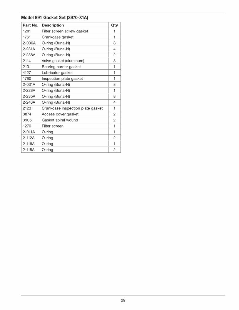
Model 891 Gasket Set (3970-X1A)
Part No . Description Qty
1281 Filter screen screw gasket 1
1761 Crankcase gasket 1
2-036A O-ring (Buna-N) 8
2-231A O-ring (Buna-N) 4
2-238A O-ring (Buna-N) 2
2114 Valve gasket (aluminum) 8
2131 Bearing carrier gasket 1
4127 Lubricator gasket 1
1760 Inspection plate gasket 1
2-031A O-ring (Buna-N) 8
2-228A O-ring (Buna-N) 1
2-235A O-ring (Buna-N) 8
2-246A O-ring (Buna-N) 4
2123 Crankcase inspection plate gasket 1
3874 Access cover gasket 2
3906 Gasket spiral wound 2
1276 Filter screen 1
2-011A O-ring 1
2-112A O-ring 2
2-116A O-ring 1
2-118A O-ring 2
29
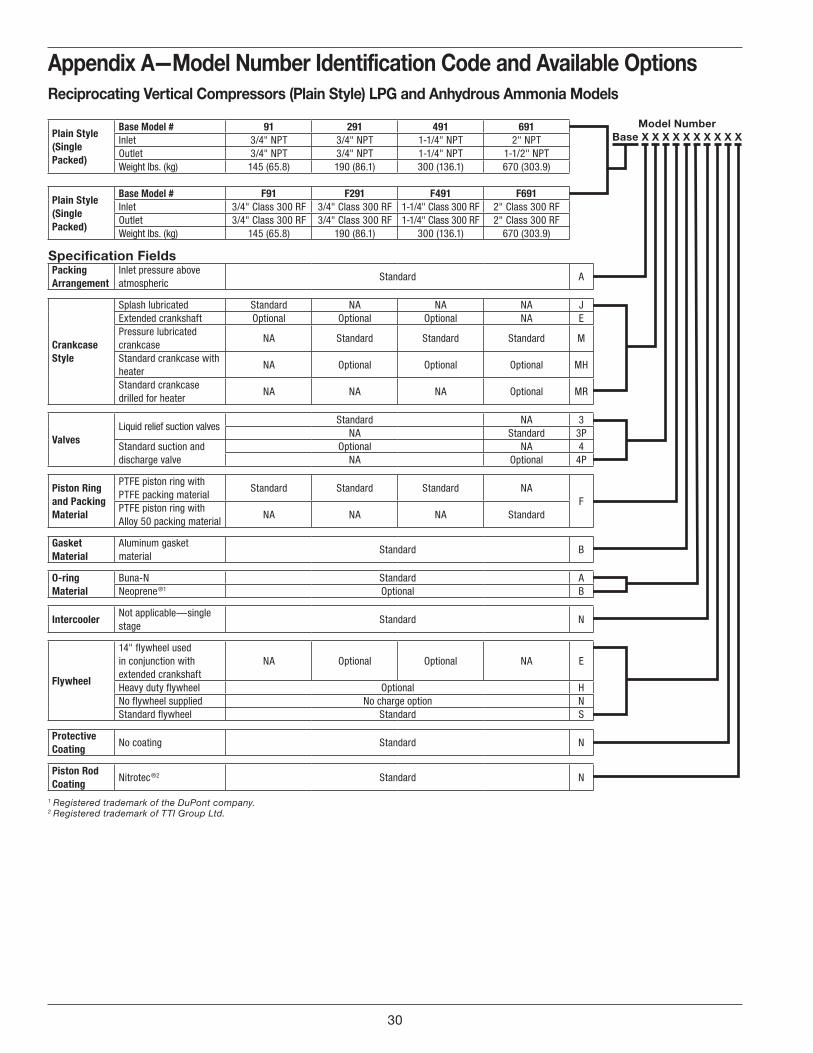
Appendices
A . Model Number Identification Code and Available Options
Appendix A—Model Number Identification Code and Available OptionsReciprocating Vertical Compressors (Plain Style) LPG and Anhydrous Ammonia Models
Plain Style (Single Packed)
Base Model # 91 291 491 691Inlet 3/4" NPT 3/4" NPT 1-1/4" NPT 2" NPTOutlet 3/4" NPT 3/4" NPT 1-1/4" NPT 1-1/2" NPTWeight lbs. (kg) 145 (65.8) 190 (86.1) 300 (136.1) 670 (303.9)
Plain Style (Single Packed)
Base Model # F91 F291 F491 F691Inlet 3/4" Class 300 RF 3/4" Class 300 RF 1-1/4" Class 300 RF 2" Class 300 RFOutlet 3/4" Class 300 RF 3/4" Class 300 RF 1-1/4" Class 300 RF 2" Class 300 RFWeight lbs. (kg) 145 (65.8) 190 (86.1) 300 (136.1) 670 (303.9)
Specification FieldsPacking Arrangement
Inlet pressure above atmospheric
Standard A
Crankcase Style
Splash lubricated Standard NA NA NA JExtended crankshaft Optional Optional Optional NA EPressure lubricated crankcase
NA Standard Standard Standard M
Standard crankcase with heater
NA Optional Optional Optional MH
Standard crankcase drilled for heater
NA NA NA Optional MR
ValvesLiquid relief suction valves
Standard NA 3NA Standard 3P
Standard suction and discharge valve
Optional NA 4NA Optional 4P
Piston Ring and Packing Material
PTFE piston ring with PTFE packing material
Standard Standard Standard NAF
PTFE piston ring with Alloy 50 packing material
NA NA NA Standard
Gasket Material
Aluminum gasket material
Standard B
O-ring Material
Buna-N Standard ANeoprene ®1 Optional B
IntercoolerNot applicable—single stage
Standard N
Flywheel
14" flywheel used in conjunction with extended crankshaft
NA Optional Optional NA E
Heavy duty flywheel Optional HNo flywheel supplied No charge option NStandard flywheel Standard S
Protective Coating
No coating Standard N
Piston Rod Coating
Nitrotec ®2 Standard N
1 Registered trademark of the DuPont company.2 Registered trademark of TTI Group Ltd.
Model NumberBase X X X X X X X X X X
30
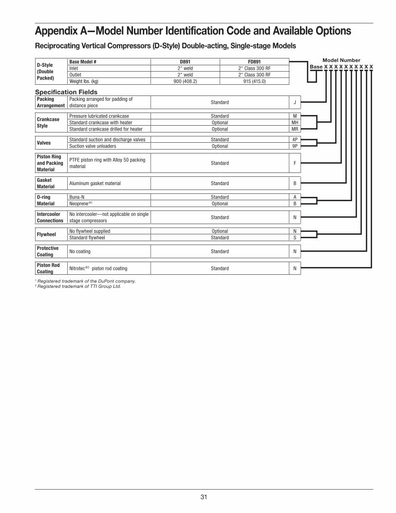
Appendix A—Model Number Identification Code and Available OptionsReciprocating Vertical Compressors (D-Style) Double-acting, Single-stage Models
D-Style (Double Packed)
Base Model # D891 FD891Inlet 2" weld 2" Class 300 RFOutlet 2" weld 2" Class 300 RFWeight lbs. (kg) 900 (408.2) 915 (415.0)
Specification FieldsPacking Arrangement
Packing arranged for padding of distance piece
Standard J
Crankcase Style
Pressure lubricated crankcase Standard MStandard crankcase with heater Optional MHStandard crankcase drilled for heater Optional MR
ValvesStandard suction and discharge valves Standard 4PSuction valve unloaders Optional 9P
Piston Ring and Packing Material
PTFE piston ring with Alloy 50 packing material
Standard F
Gasket Material
Aluminum gasket material Standard B
O-ring Material
Buna-N Standard ANeoprene ®1 Optional B
Intercooler Connections
No intercooler—not applicable on single stage compressors
Standard N
FlywheelNo flywheel supplied Optional NStandard flywheel Standard S
Protective Coating
No coating Standard N
Piston Rod Coating
Nitrotec ®2 piston rod coating Standard N
1 Registered trademark of the DuPont company.2 Registered trademark of TTI Group Ltd.
Model NumberBase X X X X X X X X X X
31
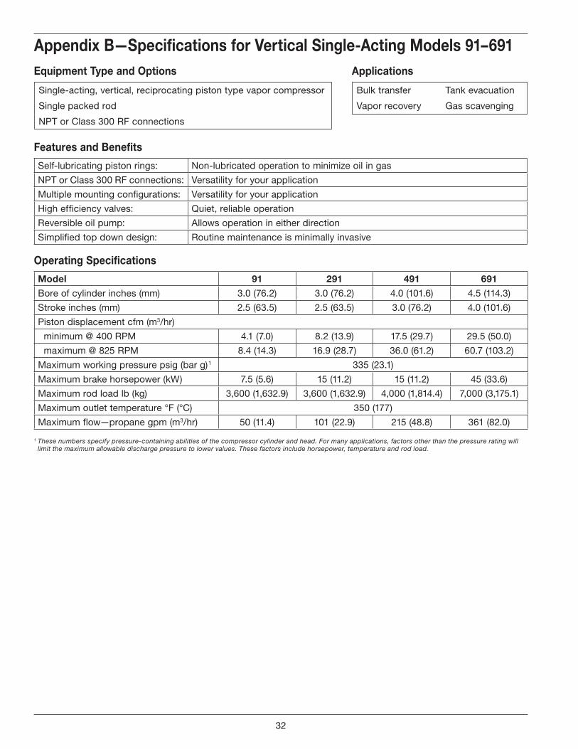
Appendix B—Specifications for Vertical Single-Acting Models 91–691
B . Specifications
Features and Benefits
Self-lubricating piston rings: Non-lubricated operation to minimize oil in gas
NPT or Class 300 RF connections: Versatility for your application
Multiple mounting configurations: Versatility for your application
High efficiency valves: Quiet, reliable operation
Reversible oil pump: Allows operation in either direction
Simplified top down design: Routine maintenance is minimally invasive
Operating Specifications
Model 91 291 491 691
Bore of cylinder inches (mm) 3.0 (76.2) 3.0 (76.2) 4.0 (101.6) 4.5 (114.3)
Stroke inches (mm) 2.5 (63.5) 2.5 (63.5) 3.0 (76.2) 4.0 (101.6)
Piston displacement cfm (m3/hr)
minimum @ 400 RPM 4.1 (7.0) 8.2 (13.9) 17.5 (29.7) 29.5 (50.0)
maximum @ 825 RPM 8.4 (14.3) 16.9 (28.7) 36.0 (61.2) 60.7 (103.2)
Maximum working pressure psig (bar g) 1 335 (23.1)
Maximum brake horsepower (kW) 7.5 (5.6) 15 (11.2) 15 (11.2) 45 (33.6)
Maximum rod load lb (kg) 3,600 (1,632.9) 3,600 (1,632.9) 4,000 (1,814.4) 7,000 (3,175.1)
Maximum outlet temperature °F (°C) 350 (177)
Maximum flow—propane gpm (m3/hr) 50 (11.4) 101 (22.9) 215 (48.8) 361 (82.0)
1 These numbers specify pressure-containing abilities of the compressor cylinder and head. For many applications, factors other than the pressure rating will limit the maximum allowable discharge pressure to lower values. These factors include horsepower, temperature and rod load.
Equipment Type and Options Applications
Single-acting, vertical, reciprocating piston type vapor compressor
Single packed rod
NPT or Class 300 RF connections
Bulk transfer
Vapor recovery
Tank evacuation
Gas scavenging
32

Appendix B—Specifications for Vertical Single-Acting Models 91–691Material Specifications
Part Model Standard Material
Head, Cylinder All Ductile iron ASTM A536
Crosshead guide crankcase, flywheel, bearing carrier All Gray iron ASTM A48, Class 30
Flange 691 Ductile iron ASTM A536
Valve seat and bumper
91, 291 17-4 PH stainless steel
491 Ductile iron ASTM A536
691 17-4 PH stainless steel
Valve plate
91, 291 410 stainless steel
491 17-7 PH stainless steel
691 PEEK
Valve spring91, 291, 691 17-7 PH stainless steel
491 Inconel
Valve gaskets None Soft aluminum
Piston All Gray iron ASTM A48, Class 30
Piston rod None 1045 steel Nitrotec ®1 coated
Crosshead All Gray iron ASTM A48, Class 30
Piston rings91, 291, 491 PTFE, glass and moly filled
691 Alloy 50
Ring expanders All 302 stainless steel
Packing cartridge, connecting rod All Ductile iron ASTM A536
Packing V-rings91, 291, 491 PTFE, glass and moly filled
691 Alloy 50
Crankshaft All Ductile iron ASTM A536
Connecting rod bearing All Bimetal D-2 babbit
Wrist pin All C1018 steel
Wrist pin busing All Bronze SAE J461
Main bearing All Tapered roller
Inspection plate All Aluminum
O-rings All Buna-N, Neoprene ®2 (optional)
Retainer rings All Steel
Misc. gaskets All Rubber compositions
1 Registered trademark of TTI Group Ltd.2 Registered trademark of the DuPont company.
33
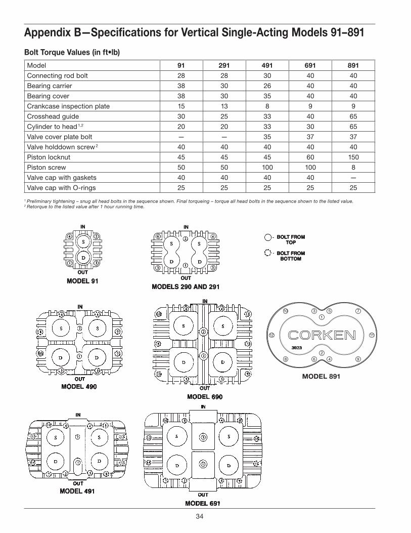
Appendix B—Specifications for Vertical Single-Acting Models 91–891
Bolt Torque Values (in ft•lb)
Model 91 291 491 691 891
Connecting rod bolt 28 28 30 40 40
Bearing carrier 38 30 26 40 40
Bearing cover 38 30 35 40 40
Crankcase inspection plate 15 13 8 9 9
Crosshead guide 30 25 33 40 65
Cylinder to head 1,2 20 20 33 30 65
Valve cover plate bolt — — 35 37 37
Valve holddown screw 2 40 40 40 40 40
Piston locknut 45 45 45 60 150
Piston screw 50 50 100 100 8
Valve cap with gaskets 40 40 40 40 —
Valve cap with O-rings 25 25 25 25 25
1 Preliminary tightening – snug all head bolts in the sequence shown. Final torqueing – torque all head bolts in the sequence shown to the listed value.2 Retorque to the listed value after 1 hour running time.
1
12 11
2
310 5 7
68 4 9
MODEL 891
34
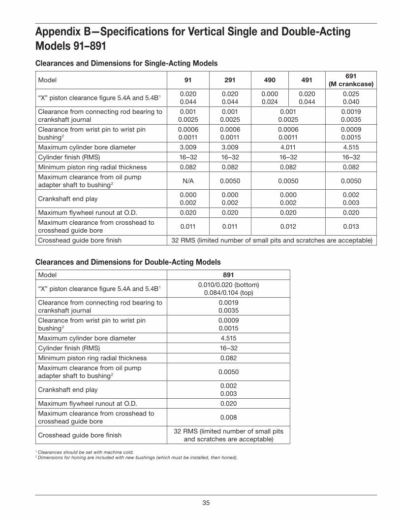
Appendix B—Specifications for Vertical Single and Double-Acting Models 91–891Clearances and Dimensions for Single-Acting Models
Model 91 291 490 491691
(M crankcase)
“X” piston clearance figure 5.4A and 5.4B 10.0200.044
0.0200.044
0.0000.024
0.0200.044
0.0250.040
Clearance from connecting rod bearing to crankshaft journal
0.0010.0025
0.0010.0025
0.0010.0025
0.00190.0035
Clearance from wrist pin to wrist pin bushing 2
0.00060.0011
0.00060.0011
0.00060.0011
0.00090.0015
Maximum cylinder bore diameter 3.009 3.009 4.011 4.515
Cylinder finish (RMS) 16–32 16–32 16–32 16–32
Minimum piston ring radial thickness 0.082 0.082 0.082 0.082
Maximum clearance from oil pump adapter shaft to bushing 2
N/A 0.0050 0.0050 0.0050
Crankshaft end play0.0000.002
0.0000.002
0.0000.002
0.0020.003
Maximum flywheel runout at O.D. 0.020 0.020 0.020 0.020
Maximum clearance from crosshead to crosshead guide bore
0.011 0.011 0.012 0.013
Crosshead guide bore finish 32 RMS (limited number of small pits and scratches are acceptable)
Clearances and Dimensions for Double-Acting Models
Model 891
“X” piston clearance figure 5.4A and 5.4B 10.010/0.020 (bottom)
0.084/0.104 (top)
Clearance from connecting rod bearing to crankshaft journal
0.00190.0035
Clearance from wrist pin to wrist pin bushing 2
0.00090.0015
Maximum cylinder bore diameter 4.515
Cylinder finish (RMS) 16–32
Minimum piston ring radial thickness 0.082
Maximum clearance from oil pump adapter shaft to bushing 2
0.0050
Crankshaft end play0.0020.003
Maximum flywheel runout at O.D. 0.020
Maximum clearance from crosshead to crosshead guide bore
0.008
Crosshead guide bore finish32 RMS (limited number of small pits
and scratches are acceptable)
1 Clearances should be set with machine cold.2 Dimensions for honing are included with new bushings (which must be installed, then honed).
35
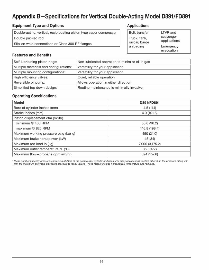
Appendix B—Specifications for Vertical Double-Acting Model D891/FD891
Features and Benefits
Self-lubricating piston rings: Non-lubricated operation to minimize oil in gas
Multiple materials and configurations: Versatility for your application
Multiple mounting configurations: Versatility for your application
High efficiency valves: Quiet, reliable operation
Reversible oil pump: Allows operation in either direction
Simplified top down design: Routine maintenance is minimally invasive
Operating Specifications
Model D891/FD891
Bore of cylinder inches (mm) 4.5 (114)
Stroke inches (mm) 4.0 (101.6)
Piston displacement cfm (m3/hr)
minimum @ 400 RPM 56.6 (96.2)
maximum @ 825 RPM 116.8 (198.4)
Maximum working pressure psig (bar g) 450 (31.0)
Maximum brake horsepower (kW) 45 (34)
Maximum rod load lb (kg) 7,000 (3,175.2)
Maximum outlet temperature °F (°C) 350 (177)
Maximum flow—propane gpm (m3/hr) 694 (157.6)
1 These numbers specify pressure-containing abilities of the compressor cylinder and head. For many applications, factors other than the pressure rating will limit the maximum allowable discharge pressure to lower values. These factors include horsepower, temperature and rod load.
Equipment Type and Options Applications
Double-acting, vertical, reciprocating piston type vapor compressor
Double packed rod
Slip-on weld connections or Class 300 RF flanges
Bulk transfer
Truck, tank, railcar, barge unloading
LTVR and scavenger applications
Emergency evacuation
36

Appendix B—Specifications for Vertical Double-Acting Model D891/FD891Material Specifications
Part Standard Material
Head, cylinder, and cylinder cap Ductile iron ASTM A536
Crosshead guide Gray iron ASTM A48, Class 30
Crankcase, flywheel Gray iron ASTM A48, Class 30
Bearing carrier Gray iron ASTM A48, Class 30
Flange ASTM A36 carbon steel (D891 only)
Valve seat, bumper 17-7 PH stainless steel
Valve plate PEEK
Valve spring 17-7 PH stainless steel
Valve gaskets Soft aluminum
Piston Ductile iron ASTM A536
Piston rod 1045 steel, Nitrotec
Crosshead Ductile iron ASTM A536
Piston rings PTFE, glass and moly filled
Piston ring expanders 302 stainless steel
Packing cartridge and barrel Ductile iron ASTM A536
Connecting rod Ductile iron ASTM A536
Segmented packing Carbon filled PTFE
V-ring packing Alloy 50
Crankshaft Ductile iron ASTM A536
Connecting rod bearing Bimetal D-2 SAE 12
Wrist pin C1018 steel or equivalent
Wrist pin bushing Bronze SAE J461
Main bearing Tapered roller
Inspection plate Aluminum
O-rings Buna-N or Neoprene ®1 (optional)
Retainer rings Steel
Miscellaneous gaskets Rubber compositions
1 Registered trademark of the DuPont company.
37

C . Compressor Selection
Appendix C—Compressor SelectionCompressor Mounting Selections
Standard 107 Items
107 Mounting• Mechanical liquid trap with ball float
107A Mounting• Automatic liquid trap with one NEMA 7 liquid
level switch
107B Mounting• Automatic liquid trap with two NEMA 7 liquid
level switches
107F Mounting• 107A or 107B with Class 300 RF flanged
components and connections
107TR Mounting• Must specify 14" flywheel and extended crankshaft
• Steel baseplate• V-belt drive• Adjustable driver side base• Enclosed steel guard• Suction and discharge
pressure gauges
• 40 Micron strainer• Non-lube 4-way valve• Interconnecting piping• Liquid trap as
specified below
Standard 109 Items
109 Mounting• Mechanical liquid trap with ball float
109A Mounting• Automatic liquid trap with one NEMA 7 liquid
level switch
109B Mounting• Automatic liquid trap with two NEMA 7 liquid
level switches
109F Mounting• 109A or 109B with Class 300 RF flanged
components and connections
109TR Mounting• Must specify 14" flywheel and extended crankshaft
• Steel baseplate• V-belt drive• Adjustable driver side base• Enclosed steel guard• Suction and discharge
pressure gauges
• 40 Micron strainer• Non-lube 4-way valve• Interconnecting piping• Liquid trap as
specified below
Interconnecting piping
Non-lube, full port,4-way valve
NEMA 7liquid levelswitch
40 meshsuction strainer
Drain valve
Steel baseplate
Liquid trap
Suction & dischargepressure gauges
Enclosed steelbeltguard Optional driver
Adjustable driver slide base
Relief valve connection
Liquid trap
Relief Valve
Two NEMA 7liquid levelswitches
Drain valve
Interconnecting piping
Suction & dischargepressure guages
Enclosed steelbeltguard
Steel baseplate Adjustable driver slide base
Optional driver
38
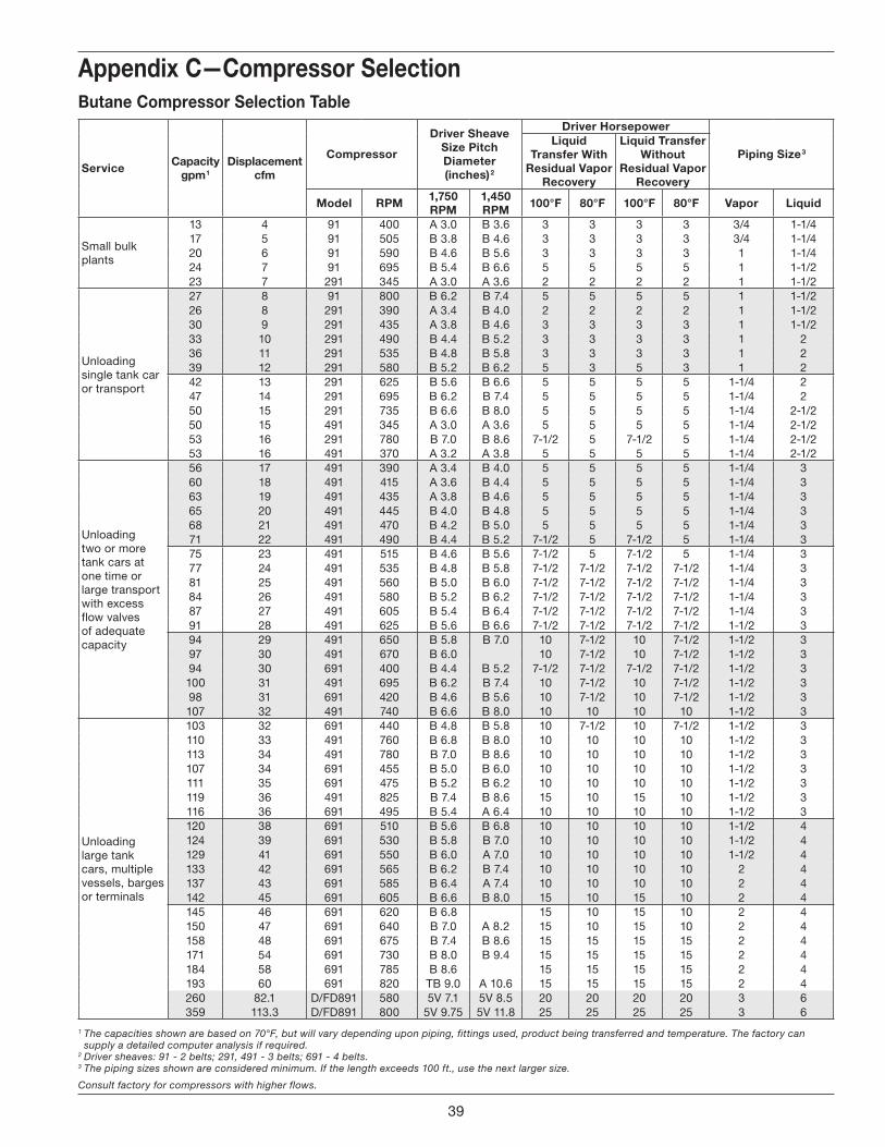
Appendix C—Compressor SelectionButane Compressor Selection Table
Service Capacitygpm 1
Displacementcfm
Compressor
Driver Sheave Size Pitch Diameter (inches) 2
Driver Horsepower
Piping Size 3Liquid
Transfer With Residual Vapor
Recovery
Liquid Transfer Without
Residual Vapor Recovery
Model RPM 1,750 RPM
1,450 RPM 100°F 80°F 100°F 80°F Vapor Liquid
Small bulk plants
13 4 91 400 A 3.0 B 3.6 3 3 3 3 3/4 1-1/417 5 91 505 B 3.8 B 4.6 3 3 3 3 3/4 1-1/420 6 91 590 B 4.6 B 5.6 3 3 3 3 1 1-1/424 7 91 695 B 5.4 B 6.6 5 5 5 5 1 1-1/223 7 291 345 A 3.0 A 3.6 2 2 2 2 1 1-1/2
Unloading single tank car or transport
27 8 91 800 B 6.2 B 7.4 5 5 5 5 1 1-1/226 8 291 390 A 3.4 B 4.0 2 2 2 2 1 1-1/230 9 291 435 A 3.8 B 4.6 3 3 3 3 1 1-1/233 10 291 490 B 4.4 B 5.2 3 3 3 3 1 236 11 291 535 B 4.8 B 5.8 3 3 3 3 1 239 12 291 580 B 5.2 B 6.2 5 3 5 3 1 242 13 291 625 B 5.6 B 6.6 5 5 5 5 1-1/4 247 14 291 695 B 6.2 B 7.4 5 5 5 5 1-1/4 250 15 291 735 B 6.6 B 8.0 5 5 5 5 1-1/4 2-1/250 15 491 345 A 3.0 A 3.6 5 5 5 5 1-1/4 2-1/253 16 291 780 B 7.0 B 8.6 7-1/2 5 7-1/2 5 1-1/4 2-1/253 16 491 370 A 3.2 A 3.8 5 5 5 5 1-1/4 2-1/2
Unloading two or more tank cars at one time or large transport with excess flow valves of adequate capacity
56 17 491 390 A 3.4 B 4.0 5 5 5 5 1-1/4 360 18 491 415 A 3.6 B 4.4 5 5 5 5 1-1/4 363 19 491 435 A 3.8 B 4.6 5 5 5 5 1-1/4 365 20 491 445 B 4.0 B 4.8 5 5 5 5 1-1/4 368 21 491 470 B 4.2 B 5.0 5 5 5 5 1-1/4 371 22 491 490 B 4.4 B 5.2 7-1/2 5 7-1/2 5 1-1/4 375 23 491 515 B 4.6 B 5.6 7-1/2 5 7-1/2 5 1-1/4 377 24 491 535 B 4.8 B 5.8 7-1/2 7-1/2 7-1/2 7-1/2 1-1/4 381 25 491 560 B 5.0 B 6.0 7-1/2 7-1/2 7-1/2 7-1/2 1-1/4 384 26 491 580 B 5.2 B 6.2 7-1/2 7-1/2 7-1/2 7-1/2 1-1/4 387 27 491 605 B 5.4 B 6.4 7-1/2 7-1/2 7-1/2 7-1/2 1-1/4 391 28 491 625 B 5.6 B 6.6 7-1/2 7-1/2 7-1/2 7-1/2 1-1/2 394 29 491 650 B 5.8 B 7.0 10 7-1/2 10 7-1/2 1-1/2 397 30 491 670 B 6.0 10 7-1/2 10 7-1/2 1-1/2 394 30 691 400 B 4.4 B 5.2 7-1/2 7-1/2 7-1/2 7-1/2 1-1/2 3100 31 491 695 B 6.2 B 7.4 10 7-1/2 10 7-1/2 1-1/2 398 31 691 420 B 4.6 B 5.6 10 7-1/2 10 7-1/2 1-1/2 3107 32 491 740 B 6.6 B 8.0 10 10 10 10 1-1/2 3
Unloading large tank cars, multiple vessels, barges or terminals
103 32 691 440 B 4.8 B 5.8 10 7-1/2 10 7-1/2 1-1/2 3110 33 491 760 B 6.8 B 8.0 10 10 10 10 1-1/2 3113 34 491 780 B 7.0 B 8.6 10 10 10 10 1-1/2 3107 34 691 455 B 5.0 B 6.0 10 10 10 10 1-1/2 3111 35 691 475 B 5.2 B 6.2 10 10 10 10 1-1/2 3119 36 491 825 B 7.4 B 8.6 15 10 15 10 1-1/2 3116 36 691 495 B 5.4 A 6.4 10 10 10 10 1-1/2 3120 38 691 510 B 5.6 B 6.8 10 10 10 10 1-1/2 4124 39 691 530 B 5.8 B 7.0 10 10 10 10 1-1/2 4129 41 691 550 B 6.0 A 7.0 10 10 10 10 1-1/2 4133 42 691 565 B 6.2 B 7.4 10 10 10 10 2 4137 43 691 585 B 6.4 A 7.4 10 10 10 10 2 4142 45 691 605 B 6.6 B 8.0 15 10 15 10 2 4145 46 691 620 B 6.8 15 10 15 10 2 4150 47 691 640 B 7.0 A 8.2 15 10 15 10 2 4158 48 691 675 B 7.4 B 8.6 15 15 15 15 2 4171 54 691 730 B 8.0 B 9.4 15 15 15 15 2 4184 58 691 785 B 8.6 15 15 15 15 2 4193 60 691 820 TB 9.0 A 10.6 15 15 15 15 2 4260 82.1 D/FD891 580 5V 7.1 5V 8.5 20 20 20 20 3 6359 113.3 D/FD891 800 5V 9.75 5V 11.8 25 25 25 25 3 6
1 The capacities shown are based on 70°F, but will vary depending upon piping, fittings used, product being transferred and temperature. The factory can supply a detailed computer analysis if required.
2 Driver sheaves: 91 - 2 belts; 291, 491 - 3 belts; 691 - 4 belts.3 The piping sizes shown are considered minimum. If the length exceeds 100 ft., use the next larger size.
Consult factory for compressors with higher flows.
39
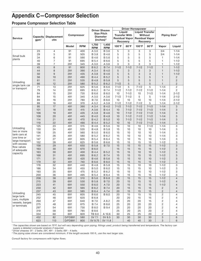
Appendix C—Compressor SelectionPropane Compressor Selection Table
Service Capacitygpm 1
Displacementcfm
Compressor
Driver Sheave Size Pitch Diameter (inches) 2
Driver Horsepower
Piping Size 3Liquid
Transfer With Residual Vapor
Recovery
Liquid Transfer Without
Residual Vapor Recovery
Model RPM 1,750 RPM
1,450 RPM 100°F 80°F 100°F 80°F Vapor Liquid
Small bulk plants
23 4 91 400 A 3.0 B 3.6 5 3 3 3 3/4 1-1/429 5 91 505 B 3.8 B 4.6 5 5 5 5 3/4 1-1/434 6 91 590 B 4.6 B 5.6 5 5 5 5 1 1-1/440 7 91 695 B 5.4 B 6.6 5 5 5 5 1 1-1/239 7 291 345 A 3.0 A 3.6 3 3 3 3 1 1-1/2
Unloading single tank car or transport
45 8 91 800 B 6.2 B 7.4 7-1/2 7-1/2 7-1/2 7-1/2 1 1-1/244 8 291 390 A 3.4 B 4.0 5 3 3 3 1 1-1/250 9 291 435 A 3.8 B 4.6 5 5 3 3 1 1-1/256 10 291 490 B 4.4 B 5.2 5 5 5 5 1 261 11 291 535 B 4.8 B 5.8 5 5 5 5 1 266 12 291 580 B 5.2 B 6.2 7-1/2 5 5 5 1 271 13 291 625 B 5.6 B 6.6 7-1/2 5 7-1/2 5 1-1/4 279 14 291 695 B 6.2 B 7.4 7-1/2 7-1/2 7-1/2 7-1/2 1-1/4 284 15 291 735 B 6.6 B 8.0 10 7-1/2 10 7-1/2 1-1/4 2-1/284 15 491 345 A 3.0 A 3.6 7-1/2 7-1/2 5 5 1-1/4 2-1/289 16 291 780 B 7.0 B 8.6 10 10 10 10 1-1/4 2-1/289 16 491 370 A 3.2 A 3.8 7-1/2 7-1/2 7-1/2 5 1-1/4 2-1/2
Unloading two or more tank cars at one time or large transport with excess flow valves of adequate capacity
95 17 491 390 A 3.4 B 4.0 7-1/2 7-1/2 7-1/2 7-1/2 1-1/4 3101 18 491 415 A 3.6 B 4.4 10 7-1/2 7-1/2 7-1/2 1-1/4 3106 19 491 435 A 3.8 B 4.6 10 7-1/2 7-1/2 7-1/2 1-1/4 3108 20 491 445 B 4.0 B 4.8 10 7-1/2 7-1/2 7-1/2 1-1/4 3114 21 491 470 B 4.2 B 5.0 10 7-1/2 7-1/2 7-1/2 1-1/4 3119 22 491 490 B 4.4 B 5.2 10 10 7-1/2 7-1/2 1-1/4 3125 23 491 515 B 4.6 B 5.6 10 10 10 7-1/2 1-1/4 3130 24 491 535 B 4.8 B 5.8 15 10 10 10 1-1/4 3136 25 491 560 B 5.0 B 6.0 15 10 10 10 1-1/4 3141 26 491 580 B 5.2 B 6.2 15 10 10 10 1-1/4 3147 27 491 605 B 5.4 B 6.4 15 10 15 10 1-1/4 3152 28 491 625 B 5.6 B 6.6 15 15 15 15 1-1/2 3158 29 491 650 B 5.8 B 7.0 15 15 15 15 1-1/2 3163 30 491 670 B 6.0 15 15 15 15 1-1/2 3163 30 691 400 B 4.4 B 5.2 15 15 10 10 1-1/2 3168 31 491 695 B 6.2 B 7.4 15 15 15 15 1-1/2 3171 31 691 420 B 4.6 B 5.6 15 15 10 10 1-1/2 3179 32 491 740 B 6.6 B 8.0 15 15 15 15 1-1/2 3178 32 691 440 B 4.8 B 5.8 15 15 10 10 1-1/2 3186 34 691 455 B 5.0 B 6.0 15 15 15 10 1-1/2 3193 35 691 475 B 5.2 B 6.2 15 15 15 10 1-1/2 3200 36 691 495 B 5.4 B 6.4 15 15 15 15 1-1/2 3
Unloading large tank cars, multiple vessels, barges or terminals
208 38 691 510 B 5.6 B 6.8 20 15 15 15 1-1/2 4215 39 691 530 B 5.8 B 7.0 20 15 15 15 1-1/2 4223 41 691 550 B 6.0 A 7.0 20 15 15 15 1-1/2 4230 42 691 565 B 6.2 B 7.4 20 15 15 15 2 4237 43 691 585 B 6.4 A 7.4 20 15 15 15 2 4245 45 691 605 B 6.6 B 8.0 20 15 15 15 2 4252 46 691 620 B 6.8 20 20 15 15 2 4260 47 691 640 B 7.0 A 8.2 20 20 20 15 2 4275 48 691 675 B 7.4 B 8.6 25 20 20 20 2 4297 54 691 730 B 8.0 B 9.4 25 20 20 20 2 4319 58 691 785 B 8.6 25 20 25 20 2 4334 60 691 820 TB 9.0 A 10.6 30 25 25 20 2 4452 82 D/FD891 580 5V 7.1 5V 8.5 30 30 30 30 3 6623 113 D/FD891 800 5V 9.75 5V 11.8 40 40 30 3 6
1 The capacities shown are based on 70°F, but will vary depending upon piping, fittings used, product being transferred and temperature. The factory can supply a detailed computer analysis if required.
2 Driver sheaves: 91 - 2 belts; 291, 491 - 3 belts; 691 - 4 belts.3 The piping sizes shown are considered minimum. If the length exceeds 100 ft., use the next larger size.
Consult factory for compressors with higher flows.
40
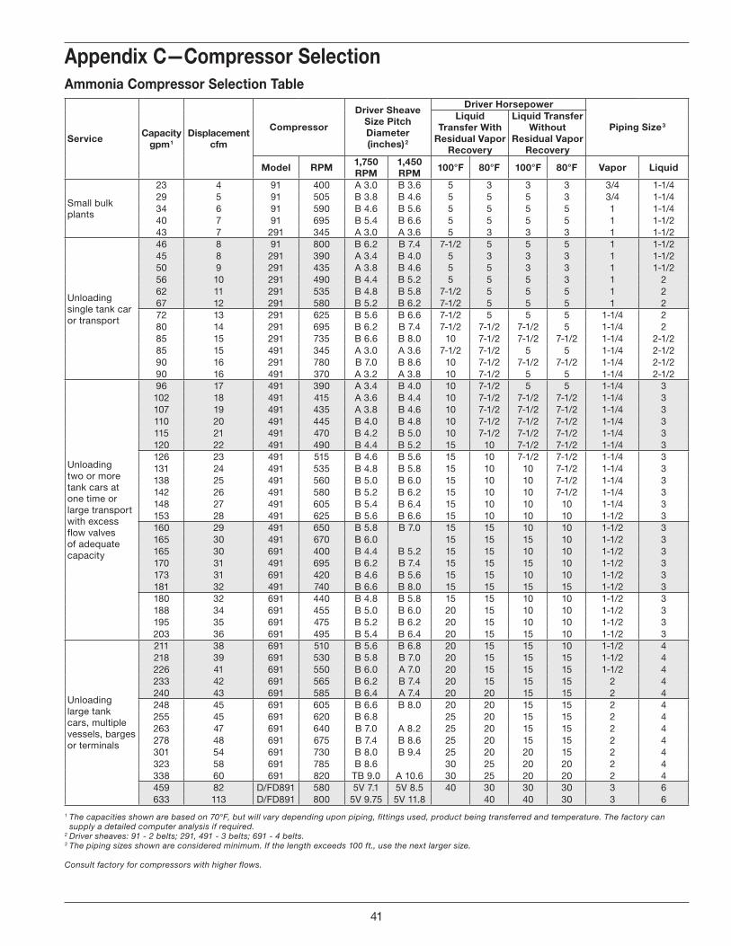
Appendix C—Compressor SelectionAmmonia Compressor Selection Table
Service Capacitygpm 1
Displacementcfm
Compressor
Driver Sheave Size Pitch Diameter (inches) 2
Driver Horsepower
Piping Size 3Liquid
Transfer With Residual Vapor
Recovery
Liquid Transfer Without
Residual Vapor Recovery
Model RPM 1,750 RPM
1,450 RPM 100°F 80°F 100°F 80°F Vapor Liquid
Small bulk plants
23 4 91 400 A 3.0 B 3.6 5 3 3 3 3/4 1-1/429 5 91 505 B 3.8 B 4.6 5 5 5 3 3/4 1-1/434 6 91 590 B 4.6 B 5.6 5 5 5 5 1 1-1/440 7 91 695 B 5.4 B 6.6 5 5 5 5 1 1-1/243 7 291 345 A 3.0 A 3.6 5 3 3 3 1 1-1/2
Unloading single tank car or transport
46 8 91 800 B 6.2 B 7.4 7-1/2 5 5 5 1 1-1/245 8 291 390 A 3.4 B 4.0 5 3 3 3 1 1-1/250 9 291 435 A 3.8 B 4.6 5 5 3 3 1 1-1/256 10 291 490 B 4.4 B 5.2 5 5 5 3 1 262 11 291 535 B 4.8 B 5.8 7-1/2 5 5 5 1 267 12 291 580 B 5.2 B 6.2 7-1/2 5 5 5 1 272 13 291 625 B 5.6 B 6.6 7-1/2 5 5 5 1-1/4 280 14 291 695 B 6.2 B 7.4 7-1/2 7-1/2 7-1/2 5 1-1/4 285 15 291 735 B 6.6 B 8.0 10 7-1/2 7-1/2 7-1/2 1-1/4 2-1/285 15 491 345 A 3.0 A 3.6 7-1/2 7-1/2 5 5 1-1/4 2-1/290 16 291 780 B 7.0 B 8.6 10 7-1/2 7-1/2 7-1/2 1-1/4 2-1/290 16 491 370 A 3.2 A 3.8 10 7-1/2 5 5 1-1/4 2-1/2
Unloading two or more tank cars at one time or large transport with excess flow valves of adequate capacity
96 17 491 390 A 3.4 B 4.0 10 7-1/2 5 5 1-1/4 3102 18 491 415 A 3.6 B 4.4 10 7-1/2 7-1/2 7-1/2 1-1/4 3107 19 491 435 A 3.8 B 4.6 10 7-1/2 7-1/2 7-1/2 1-1/4 3110 20 491 445 B 4.0 B 4.8 10 7-1/2 7-1/2 7-1/2 1-1/4 3115 21 491 470 B 4.2 B 5.0 10 7-1/2 7-1/2 7-1/2 1-1/4 3120 22 491 490 B 4.4 B 5.2 15 10 7-1/2 7-1/2 1-1/4 3126 23 491 515 B 4.6 B 5.6 15 10 7-1/2 7-1/2 1-1/4 3131 24 491 535 B 4.8 B 5.8 15 10 10 7-1/2 1-1/4 3138 25 491 560 B 5.0 B 6.0 15 10 10 7-1/2 1-1/4 3142 26 491 580 B 5.2 B 6.2 15 10 10 7-1/2 1-1/4 3148 27 491 605 B 5.4 B 6.4 15 10 10 10 1-1/4 3153 28 491 625 B 5.6 B 6.6 15 10 10 10 1-1/2 3160 29 491 650 B 5.8 B 7.0 15 15 10 10 1-1/2 3165 30 491 670 B 6.0 15 15 15 10 1-1/2 3165 30 691 400 B 4.4 B 5.2 15 15 10 10 1-1/2 3170 31 491 695 B 6.2 B 7.4 15 15 15 10 1-1/2 3173 31 691 420 B 4.6 B 5.6 15 15 10 10 1-1/2 3181 32 491 740 B 6.6 B 8.0 15 15 15 15 1-1/2 3180 32 691 440 B 4.8 B 5.8 15 15 10 10 1-1/2 3188 34 691 455 B 5.0 B 6.0 20 15 10 10 1-1/2 3195 35 691 475 B 5.2 B 6.2 20 15 10 10 1-1/2 3203 36 691 495 B 5.4 B 6.4 20 15 15 10 1-1/2 3
Unloading large tank cars, multiple vessels, barges or terminals
211 38 691 510 B 5.6 B 6.8 20 15 15 10 1-1/2 4218 39 691 530 B 5.8 B 7.0 20 15 15 15 1-1/2 4226 41 691 550 B 6.0 A 7.0 20 15 15 15 1-1/2 4233 42 691 565 B 6.2 B 7.4 20 15 15 15 2 4240 43 691 585 B 6.4 A 7.4 20 20 15 15 2 4248 45 691 605 B 6.6 B 8.0 20 20 15 15 2 4255 45 691 620 B 6.8 25 20 15 15 2 4263 47 691 640 B 7.0 A 8.2 25 20 15 15 2 4278 48 691 675 B 7.4 B 8.6 25 20 15 15 2 4301 54 691 730 B 8.0 B 9.4 25 20 20 15 2 4323 58 691 785 B 8.6 30 25 20 20 2 4338 60 691 820 TB 9.0 A 10.6 30 25 20 20 2 4459 82 D/FD891 580 5V 7.1 5V 8.5 40 30 30 30 3 6633 113 D/FD891 800 5V 9.75 5V 11.8 40 40 30 3 6
1 The capacities shown are based on 70°F, but will vary depending upon piping, fittings used, product being transferred and temperature. The factory can supply a detailed computer analysis if required.
2 Driver sheaves: 91 - 2 belts; 291, 491 - 3 belts; 691 - 4 belts.3 The piping sizes shown are considered minimum. If the length exceeds 100 ft., use the next larger size.
Consult factory for compressors with higher flows.
41
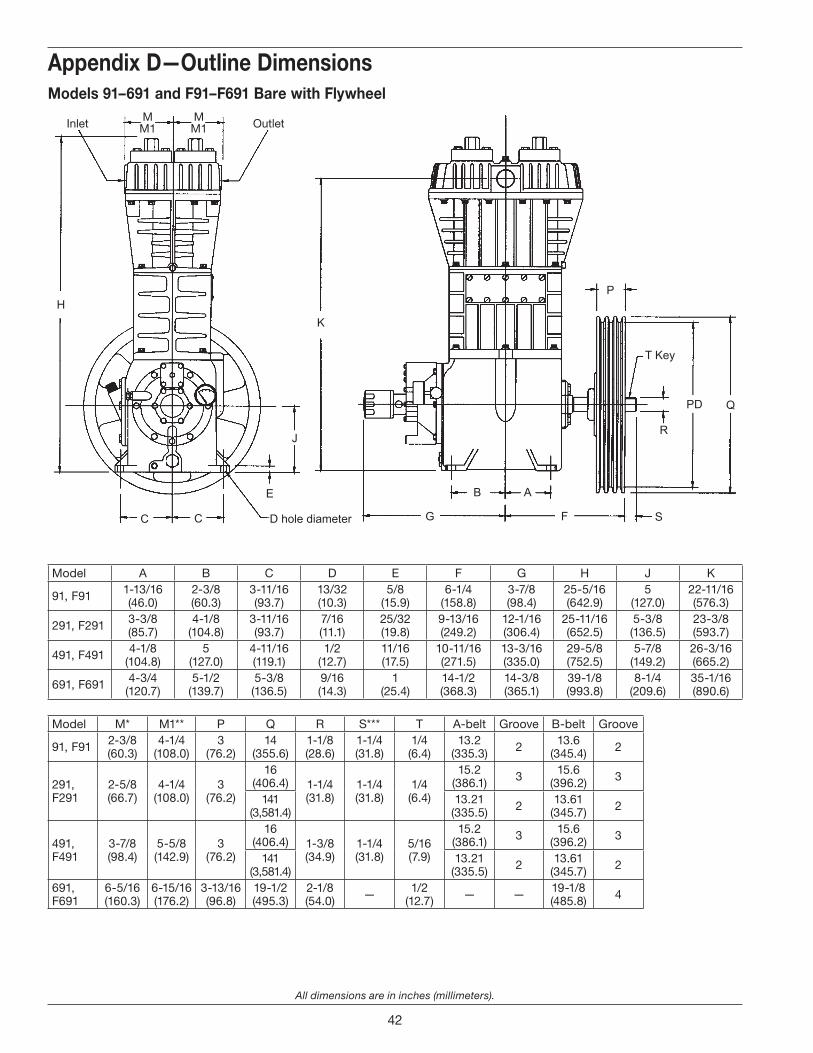
All dimensions are in inches (millimeters).
Appendix D—Outline Dimensions
D . Outline Dimensions
Appendix D—Outline DimensionsModels 91–691 and F91–F691 Bare with Flywheel
MM1Inlet OutletM
M1
S
Model A B C D E F G H J K
91, F91 1-13/16(46.0)
2-3/8(60.3)
3-11/16(93.7)
13/32(10.3)
5/8(15.9)
6-1/4(158.8)
3-7/8(98.4)
25-5/16(642.9)
5(127.0)
22-11/16(576.3)
291, F291 3-3/8(85.7)
4-1/8(104.8)
3-11/16(93.7)
7/16(11.1)
25/32(19.8)
9-13/16(249.2)
12-1/16(306.4)
25-11/16(652.5)
5-3/8(136.5)
23-3/8(593.7)
491, F491 4-1/8(104.8)
5(127.0)
4-11/16(119.1)
1/2(12.7)
11/16(17.5)
10-11/16(271.5)
13-3/16(335.0)
29-5/8(752.5)
5-7/8(149.2)
26-3/16(665.2)
691, F691 4-3/4(120.7)
5-1/2(139.7)
5-3/8(136.5)
9/16(14.3)
1(25.4)
14-1/2(368.3)
14-3/8(365.1)
39-1/8(993.8)
8-1/4(209.6)
35-1/16(890.6)
Model M* M1** P Q R S*** T A-belt Groove B-belt Groove
91, F91 2-3/8(60.3)
4-1/4(108.0)
3(76.2)
14(355.6)
1-1/8(28.6)
1-1/4(31.8)
1/4(6.4)
13.2(335.3) 2 13.6
(345.4) 2
291, F291
2-5/8(66.7)
4-1/4(108.0)
3(76.2)
16(406.4) 1-1/4
(31.8)1-1/4(31.8)
1/4(6.4)
15.2(386.1) 3 15.6
(396.2) 3
141(3,581.4)
13.21(335.5) 2 13.61
(345.7) 2
491, F491
3-7/8(98.4)
5-5/8(142.9)
3(76.2)
16(406.4) 1-3/8
(34.9)1-1/4(31.8)
5/16(7.9)
15.2(386.1) 3 15.6
(396.2) 3
141(3,581.4)
13.21(335.5) 2 13.61
(345.7) 2
691, F691
6-5/16(160.3)
6-15/16(176.2)
3-13/16(96.8)
19-1/2(495.3)
2-1/8(54.0) — 1/2
(12.7) — — 19-1/8(485.8) 4
42
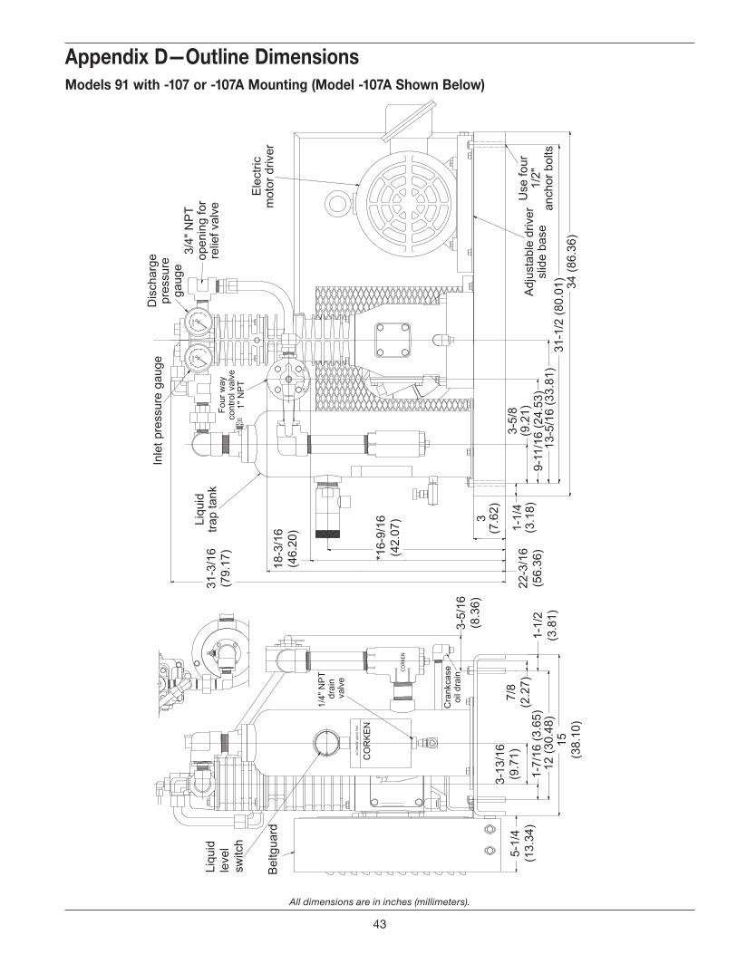
All dimensions are in inches (millimeters).
Appendix D—Outline DimensionsAppendix D—Outline DimensionsModels 91 with -107 or -107A Mounting (Model -107A Shown Below)
43
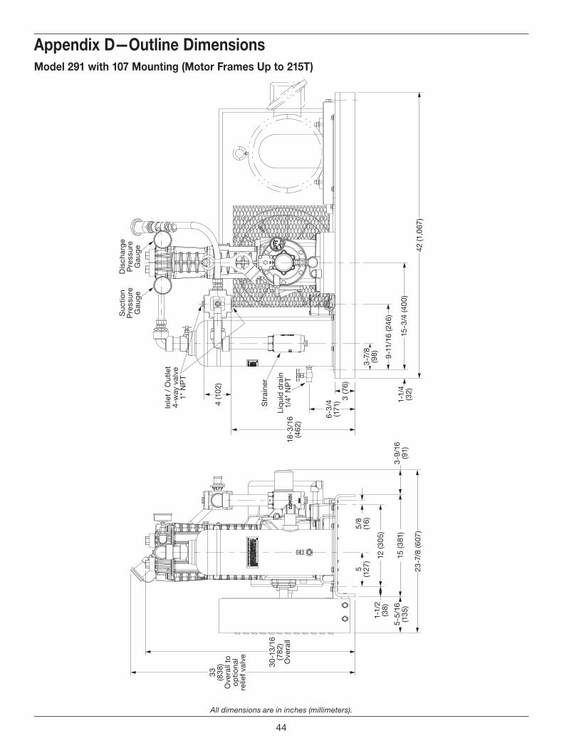
All dimensions are in inches (millimeters).
Appendix D—Outline Dimensions
5/8
(16)
5(1
27)
23-7
/8 (6
07)
42 (1
,067
)
15-3
/4 (4
00)
1-1/
4(3
2)
9-1
1/16
(246
)
3-7/
8(9
8)
6-3
/4
(171
)
18-3
/16
(462
)
3 (7
6)
4 (1
02)
12 (3
05)
1-1/
2(3
8)
15 (3
81)
5-5
/16
(135
)3-
9/16
(91)
33 (838
)O
vera
ll to
o
ptio
nal
relie
f val
ve
30-1
3/16
(782
)O
vera
llLi
qui
d d
rain
1/4"
NP
T
Inle
t /
Out
let
4-w
ay v
alve
1" N
PT
Str
aine
r
Suc
tion
Pre
ssur
eG
aug
e
Dis
char
ge
Pre
ssur
eG
aug
e
Model 291 with 107 Mounting (Motor Frames Up to 215T)
44
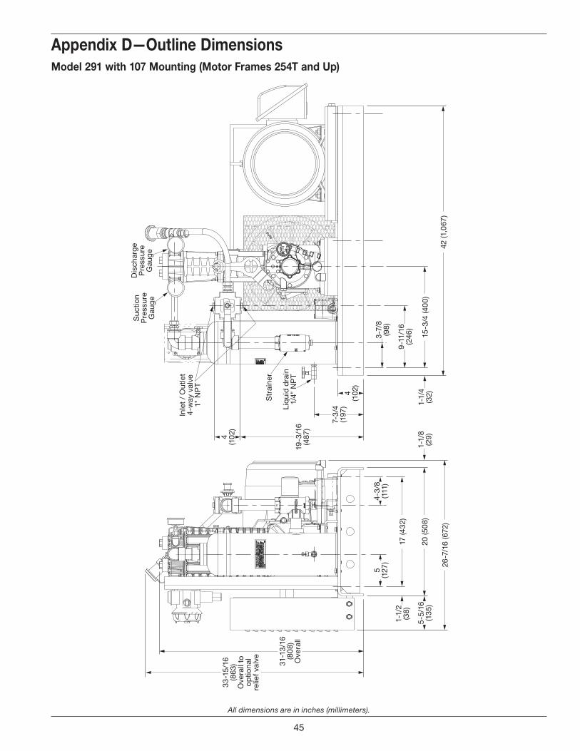
All dimensions are in inches (millimeters).
Appendix D—Outline DimensionsModel 291 with 107 Mounting (Motor Frames 254T and Up)
42 (1
,067
)
15-3
/4 (4
00)
26-7
/16
(672
)
20 (5
08)
17 (4
32)
9-1
1/16
(2
46)
7-3/
4(1
97)
19-3
/16
(487
)
31-1
3/16
(808
)O
vera
ll
33-1
5/16
(863
)O
vera
ll to
o
ptio
nal
relie
f val
ve
3-7/
8(9
8)
4(1
02)
4(1
02)
1-1/
4(3
2)1-
1/8
(29)
1-1/
2(3
8)
5(1
27)
5-5
/16
(135
)
4-3/
8(1
11)
Liq
uid
dra
in1/
4" N
PT
Str
aine
r
Inle
t /
Out
let
4-w
ay v
alve
1" N
PT
Suc
tion
Pre
ssur
eG
aug
e
Dis
char
ge
Pre
ssur
eG
aug
e
45
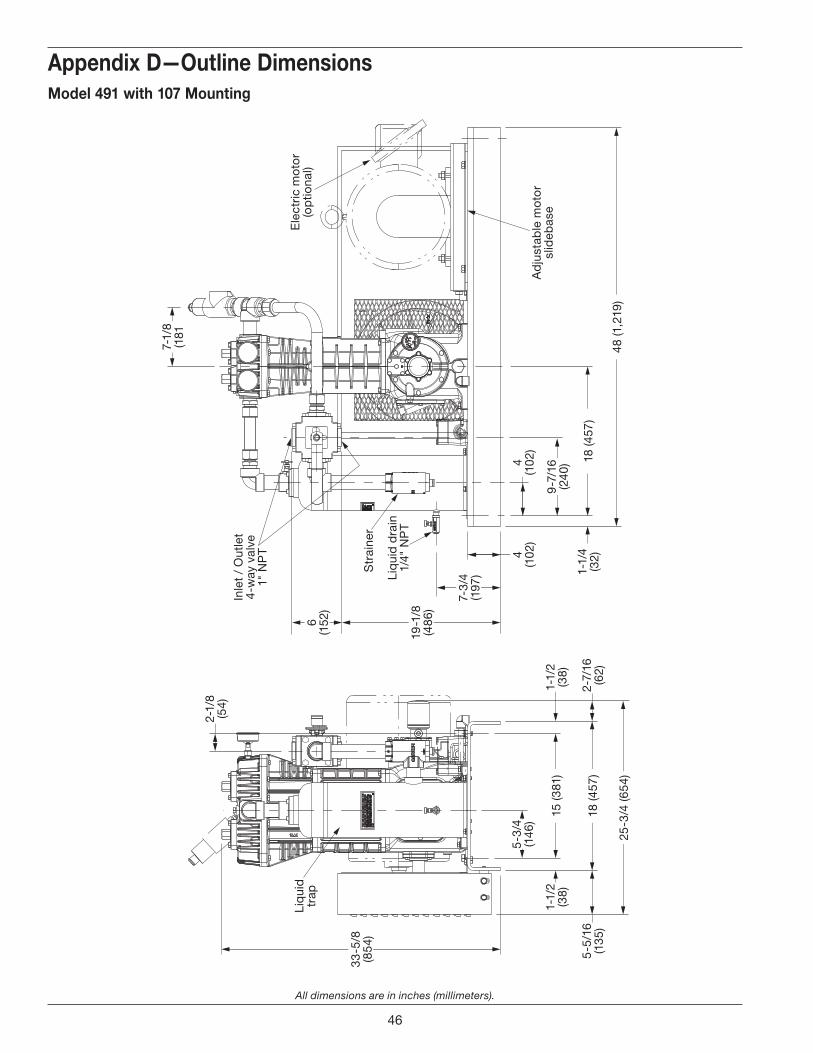
All dimensions are in inches (millimeters).
Appendix D—Outline DimensionsModel 491 with 107 Mounting
48 (1
,219
)25
-3/4
(654
)
15 (3
81)
18 (4
57)
18 (4
57)
9-7
/16
(240
)
7-1/
8(1
81
4(1
02)
4(1
02)
7-3/
4(1
97)
5-3
/4(1
46)
5-5
/16
(135
)2-
7/16
(62)
2-1/
8(5
4)
1-1/
2(3
8)1-
1/2
(38)
19-1
/8(4
86)
33-5
/8(8
54)
6(1
52)
1-1/
4(3
2)
Liq
uid
dra
in1/
4" N
PT
Str
aine
r
Liq
uid
trap
Ad
just
able
mot
or
slid
ebas
e
Ele
ctri
c m
oto
r(o
ptio
nal)
Inle
t /
Out
let
4-w
ay v
alve
1" N
PT
46
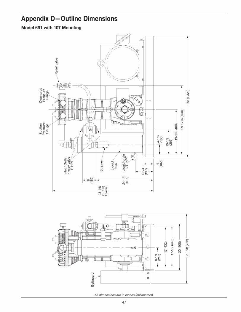
All dimensions are in inches (millimeters).
Appendix D—Outline DimensionsModel 691 with 107 Mounting
29-9
/16
(750
)20
(508
)
17 (4
32)
29-7
/8 (7
58)
19-1
/4 (4
89)
52 (1
,321
)
8-1
/4(2
10)
10-1
/2(2
67)
4-1/
8(1
05)
Liq
uid
dra
in1/
4" N
PT
Bel
tgua
rd
Liq
uid
trap
Str
aine
r
Rel
ief v
alve
4(1
02)
7-3/
4(1
97)
6(1
52)
24-1
/4(6
16)
43-1
/8(1
,095
)O
vera
ll
Inle
t /
Out
let
4-w
ay v
alve
1" N
PT
Suc
tion
Pre
ssur
eG
aug
e
Dis
char
ge
Pre
ssur
eG
aug
e
17-1
/2 (4
45)
47
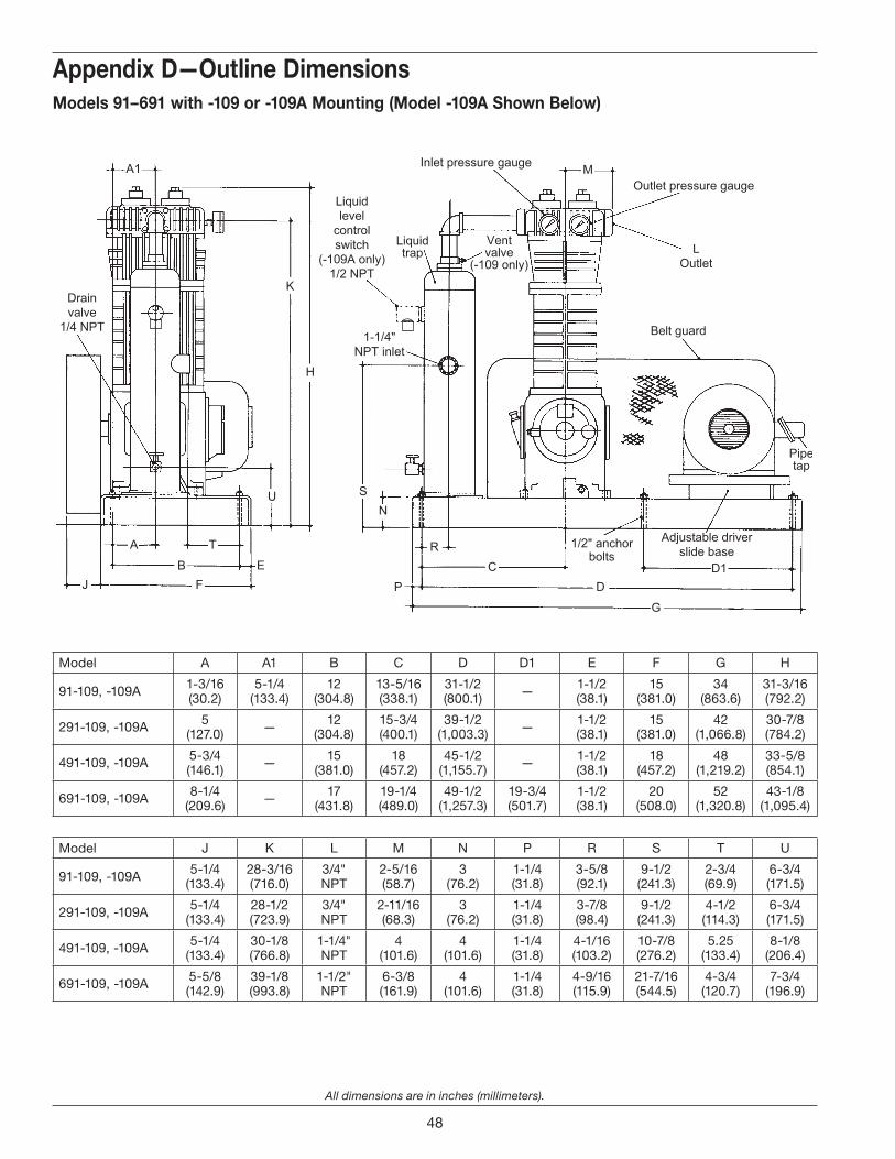
All dimensions are in inches (millimeters).
Appendix D—Outline Dimensions
Model A A1 B C D D1 E F G H
91-109, -109A 1-3/16(30.2)
5-1/4(133.4)
12(304.8)
13-5/16(338.1)
31-1/2(800.1) — 1-1/2
(38.1)15
(381.0)34
(863.6)31-3/16(792.2)
291-109, -109A 5(127.0) — 12
(304.8)15-3/4(400.1)
39-1/2(1,003.3) — 1-1/2
(38.1)15
(381.0)42
(1,066.8)30-7/8(784.2)
491-109, -109A 5-3/4(146.1) — 15
(381.0)18
(457.2)45-1/2
(1,155.7) — 1-1/2(38.1)
18(457.2)
48(1,219.2)
33-5/8(854.1)
691-109, -109A 8-1/4(209.6) — 17
(431.8)19-1/4(489.0)
49-1/2(1,257.3)
19-3/4(501.7)
1-1/2(38.1)
20(508.0)
52(1,320.8)
43-1/8(1,095.4)
Model J K L M N P R S T U
91-109, -109A 5-1/4(133.4)
28-3/16(716.0)
3/4" NPT
2-5/16(58.7)
3(76.2)
1-1/4(31.8)
3-5/8(92.1)
9-1/2(241.3)
2-3/4(69.9)
6-3/4(171.5)
291-109, -109A 5-1/4(133.4)
28-1/2(723.9)
3/4" NPT
2-11/16(68.3)
3(76.2)
1-1/4(31.8)
3-7/8(98.4)
9-1/2(241.3)
4-1/2(114.3)
6-3/4(171.5)
491-109, -109A 5-1/4(133.4)
30-1/8(766.8)
1-1/4" NPT
4(101.6)
4(101.6)
1-1/4(31.8)
4-1/16(103.2)
10-7/8(276.2)
5.25(133.4)
8-1/8(206.4)
691-109, -109A 5-5/8 (142.9)
39-1/8(993.8)
1-1/2" NPT
6-3/8(161.9)
4(101.6)
1-1/4(31.8)
4-9/16(115.9)
21-7/16(544.5)
4-3/4(120.7)
7-3/4(196.9)
Models 91–691 with -109 or -109A Mounting (Model -109A Shown Below)
48
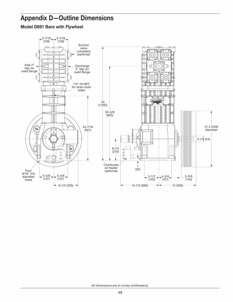
All dimensions are in inches (millimeters).
Appendix D—Outline Dimensions
Inlet 2" slip-on
weld �ange
14-1/2 (369)9-1/4 (235) 14 (356)
2-1/8 (54)
21.2 (539) diameter
4-3/4(121)
5-1/2(140)
5-3/8(137)
5-7/16(139)
5-7/16(139)
5-3/8(137)
8-1/4(210)
24-7/16(621)
35-5/8(905)
43(1,092)
1(25)
5-5/8(143)
Crankcaseoil heater(optional)
Discharge 2" slip-on
weld �ange
1/4"-18 NPT for drain-both
sides
Four9/16" (14) diameter
holes
Suction valve
unloaders (optional)
Model D891 Bare with Flywheel
49
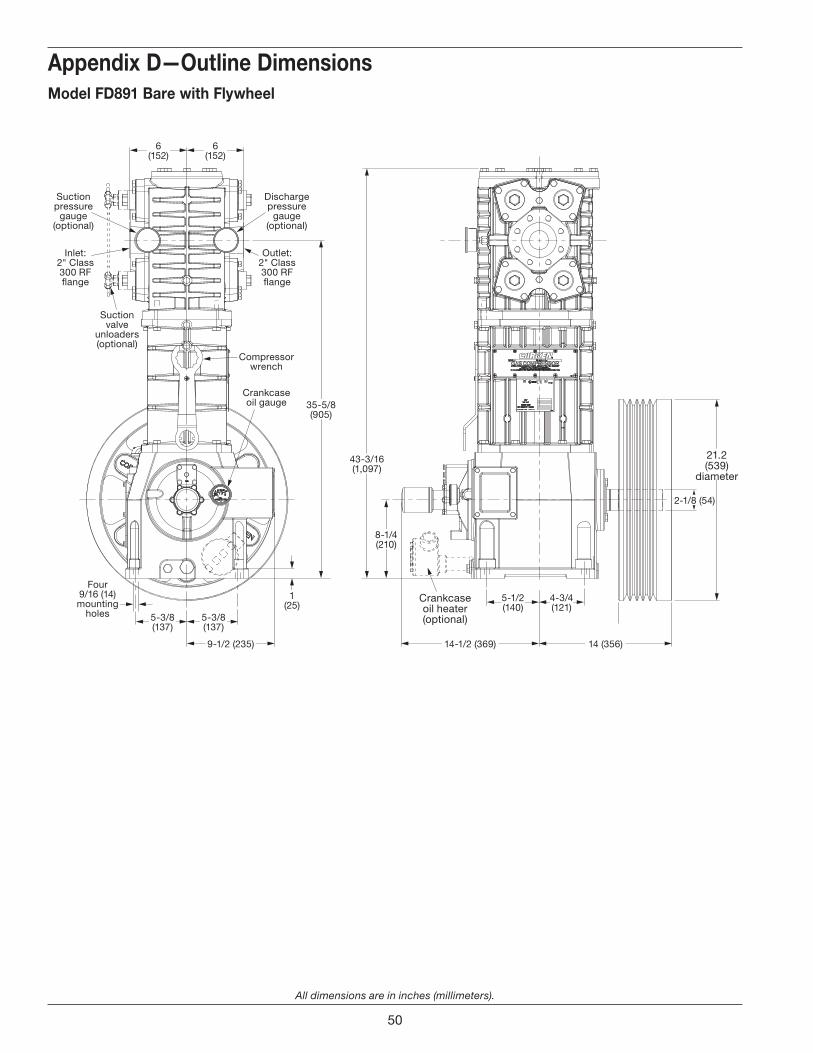
All dimensions are in inches (millimeters).
Appendix D—Outline DimensionsModel FD891 Bare with Flywheel
2-1/8 (54)
21.2 (539)
diameter
14-1/2 (369)9-1/2 (235) 14 (356)
5-1/2(140)
6(152)
6(152)
8-1/4(210)
43-3/16(1,097)
35-5/8(905)
5-3/8(137)
5-3/8(137)
1(25)
4-3/4(121)
Outlet:2" Class 300 RF �ange
Discharge pressure
gauge (optional)
Inlet:2" Class 300 RF �ange
Suction pressure
gauge (optional)
Suction valve
unloaders (optional)
Four9/16 (14)mounting
holes
Compressorwrench
Crankcaseoil gauge
Crankcaseoil heater(optional)
50
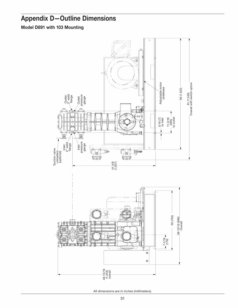
All dimensions are in inches (millimeters).
Appendix D—Outline DimensionsModel D891 with 103 Mounting
56 (1
,422
)
30 (7
62)
61 (1
,549
)O
vera
ll w
ith s
witc
h o
ptio
n
38-1
3/16
(986
)O
vera
ll
7-1/
16(1
79)
41-5
/8(1
,057
)
48-1
5/16
(1,2
43)
over
all
11-3
/16
(285
)to
out
let
5/16
(7)
to in
let
Out
let:
2" w
eld
�a
nge
Inle
t:2"
wel
d
�ang
e
Out
let
pre
ssur
e g
aug
e
Inle
t p
ress
ure
gau
ge
Suc
tion
valv
e un
load
ers
(op
tiona
l)
Ad
just
able
mo
tor
slid
ebas
e
51

All dimensions are in inches (millimeters).
Appendix D—Outline DimensionsModel FD891 with 103 Mounting
56 (1
,423
)30
(762
)
61 (1
,550
)O
vera
ll w
ith s
witc
hes
39 (9
91)
Ove
rall
5-3
/4(1
47)
7-1/
16
(180
)
6(1
52)
6(1
52)
41-5
/8(1
,058
)
Out
let:
2" C
lass
30
0 R
F �a
nge
Inle
t:2"
Cla
ss 3
00
RF
�ang
e
Out
let
pre
ssur
e g
aug
e
Inle
t p
ress
ure
gau
ge
Suc
tion
valv
e un
load
ers
(op
tiona
l)
49-3
/16
(1,2
50)
over
all
52
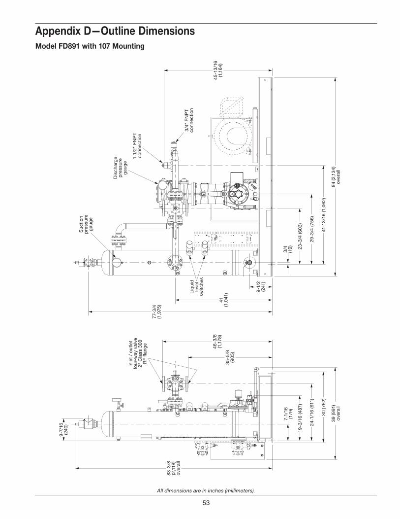
All dimensions are in inches (millimeters).
Appendix D—Outline Dimensions
84 (2
,134
)ov
eral
l
41-1
3/16
(1,0
62)
39 (9
91)
over
all
30 (7
62)
24-1
/16
(611
)
19-3
/16
(487
)
29-3
/4 (7
56)
23-3
/4 (6
03)
9-1
/2(2
41)
35-5
/8(9
05)
46-3
/8(1
,178
)
83-3
/8(2
,118
)ov
eral
l
7-1/
16(1
79)
9-7
/16
(240
)
41(1
,041
)
45-1
3/16
(1,1
64)
77-3
/4(1
,975
)
3/4
(19)
1-1/
2" F
NP
T co
nnec
tion
Dis
char
ge
pre
ssur
e g
aug
e
Suc
tion
pre
ssur
e g
aug
e
3/4"
FN
PT
conn
ectio
n
Inle
t /
out
let
four
-way
val
ve
2" C
lass
30
0 R
F �a
nge
Liq
uid
le
vel
switc
hes
Model FD891 with 107 Mounting
53
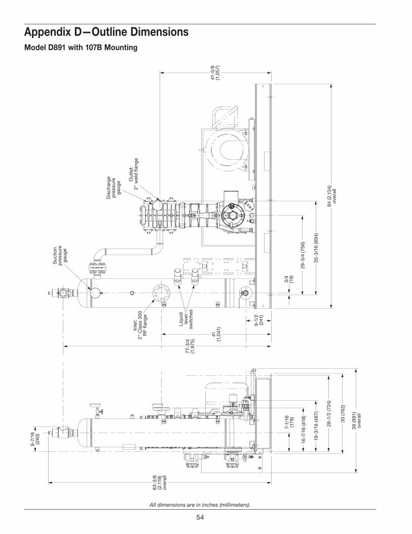
All dimensions are in inches (millimeters).
Appendix D—Outline Dimensions
84 (2
,134
)ov
eral
l
35-3
/16
(894
)
Out
let:
2" w
eld
�an
ge
Inle
t:2"
Cla
ss 3
00
RF
�ang
e
Dis
char
ge
pre
ssur
e g
aug
e
Suc
tion
pre
ssur
e g
aug
e
Liq
uid
le
vel
switc
hes
3/4
(19)
29-3
/4 (7
56)
9-1
/2(2
41)
41(1
,041
)
77-3
/4(1
,975
)
39 (9
91)
over
all
30 (7
62)
28-1
/2 (7
24)
19-3
/16
(487
)
16-7
/16
(418
)
7-1/
16(1
79)
83-3
/8(2
,118
)ov
eral
l
41-5
/8(1
,057
)
9-7
/16
(240
)
Model D891 with 107B Mounting
54

All dimensions are in inches (millimeters).
Appendix D—Outline DimensionsModel FD891 with 107B Mounting
84 (2
,134
)ov
eral
l
43-5
/16
(1,1
00)
29-3
/4 (7
56)
23-3
/4 (6
03)
3/4
(19)
39 (9
91)
over
all
30 (7
62)
24-1
/16
(611
)
19-3
/16
(487
)
7-1/
16(1
79)
9-1
/2(2
41)
35-5
/8(9
05)
46-3
/8(1
,178
)
83-3
/8(2
,118
)ov
eral
l
9-7
/16
(240
)
41(1
,041
)
45-1
3/16
(1,1
64)
77-3
/4(1
,975
)
1-1/
2" F
NP
T co
nnec
tion
Dis
char
ge
pre
ssur
e g
aug
e
Suc
tion
pre
ssur
e g
aug
e
3/4"
FN
PT
conn
ectio
nB
eltg
uard
Inle
t /
out
let
four
-way
val
ve
2" C
lass
30
0 R
F �a
nge
Liq
uid
le
vel
switc
hes
55
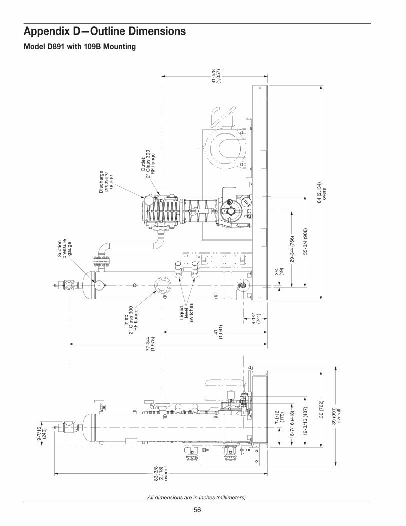
All dimensions are in inches (millimeters).
Appendix D—Outline DimensionsModel D891 with 109B Mounting
84 (2
,134
)ov
eral
l
35-3
/4 (9
08)
29-3
/4 (7
56)
41-5
/8(1
,057
)
3/4
(19)
39 (9
91)
over
all
30 (7
62)
16-7
/16
(418
)
19-3
/16
(487
)
7-1/
16(1
79)
9-1
/2(2
41)
83-3
/8(2
,118
)ov
eral
l
9-7
/16
(240
)
41(1
,041
)
77-3
/4(1
,975
)
Out
let:
2" C
lass
30
0 R
F �a
nge
Inle
t:2"
Cla
ss 3
00
RF
�ang
e
Dis
char
ge
pre
ssur
e g
aug
e
Suc
tion
pre
ssur
e g
aug
e
Liq
uid
le
vel
switc
hes
56

57
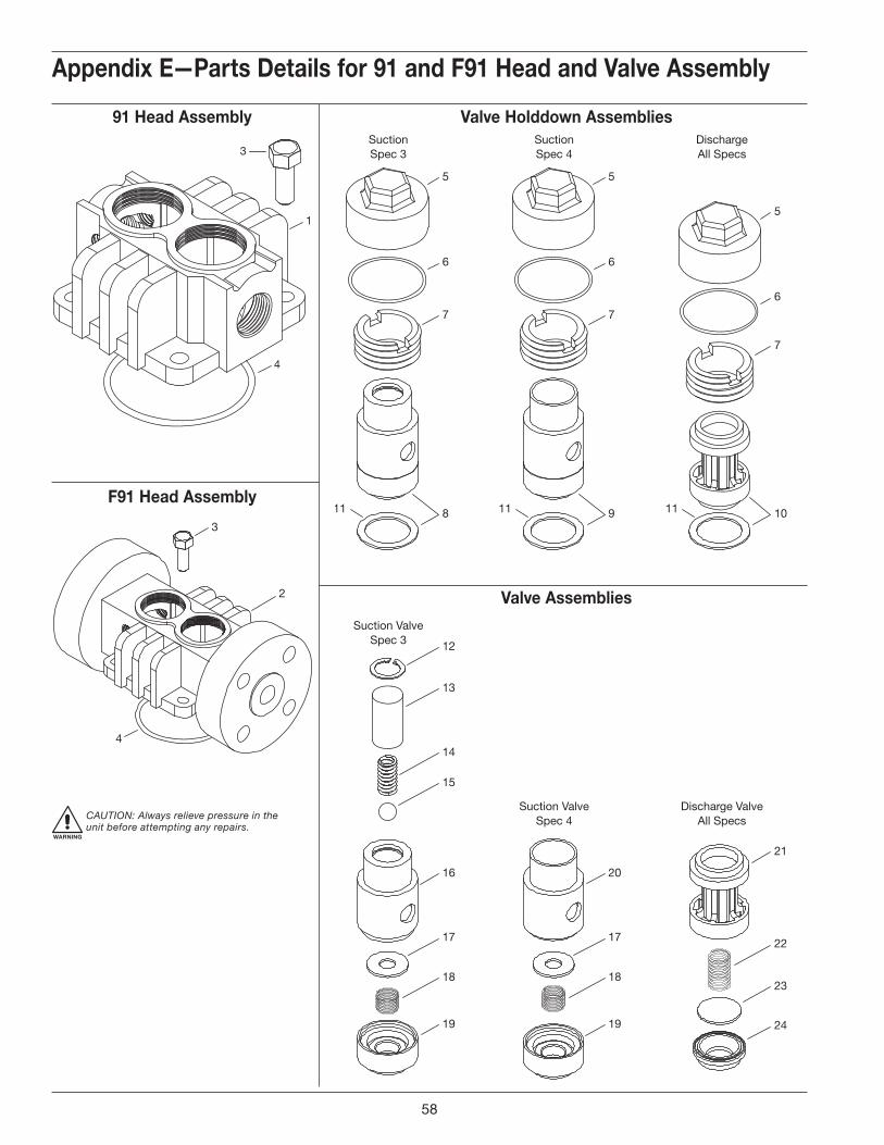
5
7
6
5
7
6
11 1111
5
7
6
1098
SuctionSpec 3
SuctionSpec 4
DischargeAll Specs
Suction ValveSpec 3
Suction ValveSpec 4
Discharge ValveAll Specs
12
13
14
15
16
17
18
19
20
17
18
19
21
22
23
24
1
3
4
3
2
4
E . Parts DetailsModel 91 and F91
Appendix E—Parts Details for 91 and F91 Head and Valve Assembly
Valve Holddown Assemblies91 Head Assembly
F91 Head Assembly
Valve Assemblies
WARNING
CAUTION: Always relieve pressure in the unit before attempting any repairs.
58
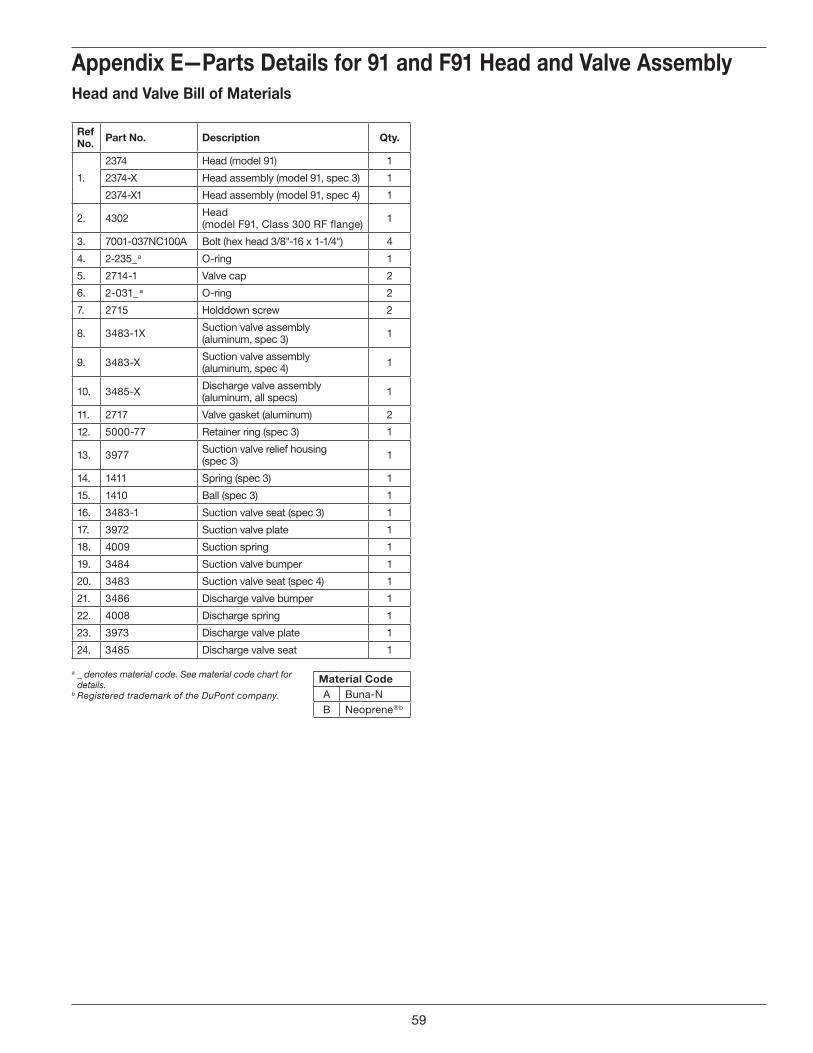
Appendix E—Parts Details for 91 and F91 Head and Valve AssemblyHead and Valve Bill of Materials
Ref No . Part No . Description Qty .
1.
2374 Head (model 91) 1
2374-X Head assembly (model 91, spec 3) 1
2374-X1 Head assembly (model 91, spec 4) 1
2. 4302 Head (model F91, Class 300 RF flange) 1
3. 7001-037NC100A Bolt (hex head 3/8"-16 x 1-1/4") 4
4. 2-235_ a O-ring 1
5. 2714-1 Valve cap 2
6. 2-031_ a O-ring 2
7. 2715 Holddown screw 2
8. 3483-1X Suction valve assembly (aluminum, spec 3) 1
9. 3483-X Suction valve assembly (aluminum, spec 4) 1
10. 3485-X Discharge valve assembly (aluminum, all specs) 1
11. 2717 Valve gasket (aluminum) 2
12. 5000-77 Retainer ring (spec 3) 1
13. 3977 Suction valve relief housing(spec 3) 1
14. 1411 Spring (spec 3) 1
15. 1410 Ball (spec 3) 1
16. 3483-1 Suction valve seat (spec 3) 1
17. 3972 Suction valve plate 1
18. 4009 Suction spring 1
19. 3484 Suction valve bumper 1
20. 3483 Suction valve seat (spec 4) 1
21. 3486 Discharge valve bumper 1
22. 4008 Discharge spring 1
23. 3973 Discharge valve plate 1
24. 3485 Discharge valve seat 1
a _ denotes material code. See material code chart for details.
b Registered trademark of the DuPont company.
Material CodeA Buna-NB Neoprene ®b
59
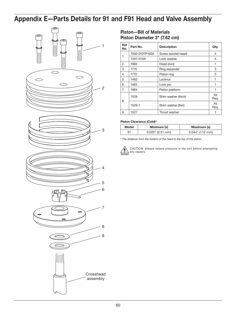
5
6
7
8
9
Crossheadassembly
4
3
2
1
Appendix E—Parts Details for 91 and F91 Head and Valve Assembly
Piston—Bill of MaterialsPiston Diameter 3" (7 .62 cm)Ref No . Part No . Description Qty .
1.7002-010TP100A Screw (socket head) 4
7207-010A Lock washer 4
2. 1983 Head (iron) 1
3. 1775 Ring expander 3
4. 1772 Piston ring 3
5. 1482 Locknut 1
6. 1483 Lock pin 1
7. 1984 Piston platform 1
8.1528 Shim washer (thick) As
Req.
1528-1 Shim washer (thin) As Req.
9. 1527 Thrust washer 1
Piston Clearance (Cold) a
Model Minimum (x) Maximum (x)
91 0.020" (0.51 mm) 0.044" (1.12 mm)
a The distance from the bottom of the head to the top of the piston.
WARNING
CAUTION: Always relieve pressure in the unit before attempting any repairs.
60
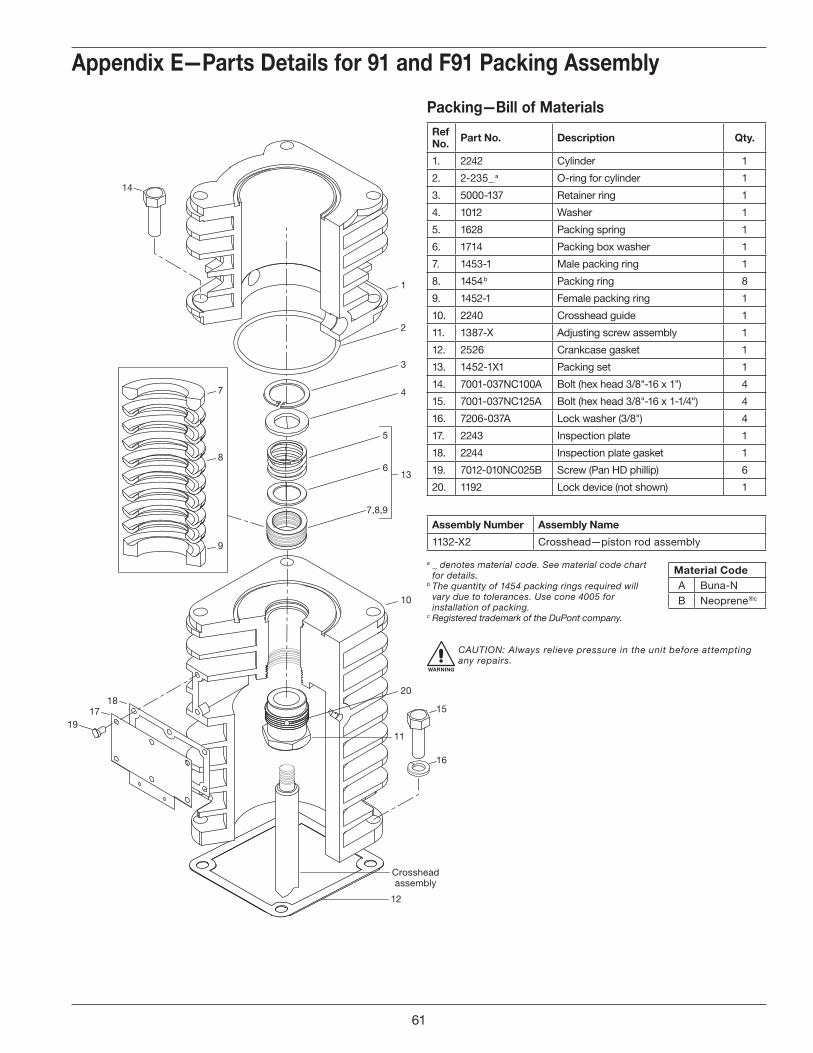
Crossheadassembly
1
2
3
4
13
20
5
6
7,8,9
7
8
9
10
11
12
14
1817
19
15
16
Appendix E—Parts Details for 91 and F91 Packing Assembly
Packing—Bill of MaterialsRef No . Part No . Description Qty .
1. 2242 Cylinder 1
2. 2-235_ a O-ring for cylinder 1
3. 5000-137 Retainer ring 1
4. 1012 Washer 1
5. 1628 Packing spring 1
6. 1714 Packing box washer 1
7. 1453-1 Male packing ring 1
8. 1454 b Packing ring 8
9. 1452-1 Female packing ring 1
10. 2240 Crosshead guide 1
11. 1387-X Adjusting screw assembly 1
12. 2526 Crankcase gasket 1
13. 1452-1X1 Packing set 1
14. 7001-037NC100A Bolt (hex head 3/8"-16 x 1") 4
15. 7001-037NC125A Bolt (hex head 3/8"-16 x 1-1/4") 4
16. 7206-037A Lock washer (3/8") 4
17. 2243 Inspection plate 1
18. 2244 Inspection plate gasket 1
19. 7012-010NC025B Screw (Pan HD phillip) 6
20. 1192 Lock device (not shown) 1
Assembly Number Assembly Name
1132-X2 Crosshead—piston rod assembly
a _ denotes material code. See material code chart for details.
b The quantity of 1454 packing rings required will vary due to tolerances. Use cone 4005 for installation of packing.
c Registered trademark of the DuPont company.
WARNING
CAUTION: Always relieve pressure in the unit before attempting any repairs.
Material CodeA Buna-NB Neoprene ®c
61
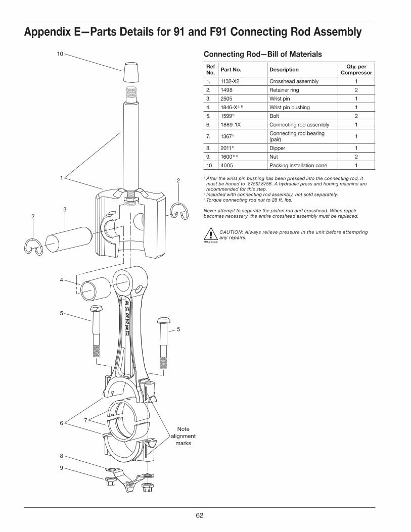
5
Notealignment
marks
7
1
4
2
5
8
9
10
6
3
2
Appendix E—Parts Details for 91 and F91 Connecting Rod Assembly
Connecting Rod—Bill of MaterialsRef No . Part No . Description Qty . per
Compressor
1. 1132-X2 Crosshead assembly 1
2. 1498 Retainer ring 2
3. 2505 Wrist pin 1
4. 1846-X a, b Wrist pin bushing 1
5. 1599 b Bolt 2
6. 1889-1X Connecting rod assembly 1
7. 1367 b Connecting rod bearing (pair) 1
8. 2011 b Dipper 1
9. 1600 b, c Nut 2
10. 4005 Packing installation cone 1
a After the wrist pin bushing has been pressed into the connecting rod, it must be honed to .8759/.8756. A hydraulic press and honing machine are recommended for this step.
b Included with connecting rod assembly, not sold separately.c Torque connecting rod nut to 28 ft. lbs.
Never attempt to separate the piston rod and crosshead. When repair becomes necessary, the entire crosshead assembly must be replaced.
WARNING
CAUTION: Always relieve pressure in the unit before attempting any repairs.
62

Back Side
1
Front Side
1
2
2
2
2
2
22
Appendix E—Parts Details for 91 and F91 Flywheel Assembly
Flywheel—Bill of MaterialsRef No . Part No . Description Qty .
1. 3271 Flywheel (14" O.D., 2 groove) 1
2. H SF-1.125 Hub with three bolts and lockwashers 1
Assembly Number Assembly Name
3271-X2 Flywheel assembly (flywheel, hub, and three bolts) standard
63
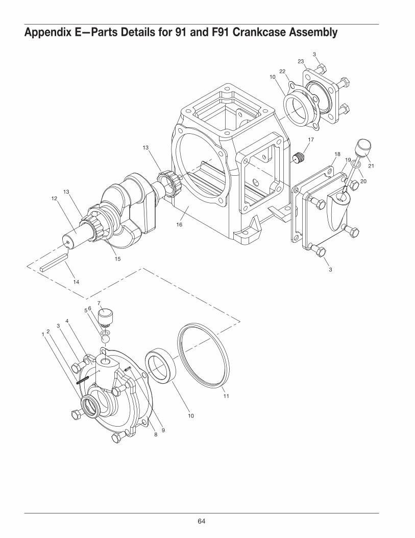
17
323
2210
13
1312
1 23
4
5 67
15
16
14
89
10
11
18
20
19
3
21
a Not shown.b _ denotes material code. See material code chart for details.c Optional. d Registered trademark of the DuPont company.
Appendix E—Parts Details for 91 and F91 Crankcase Assembly
64
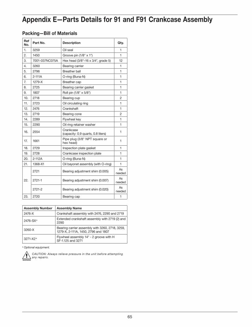
Appendix E—Parts Details for 91 and F91 Crankcase Assembly
Packing—Bill of MaterialsRef No . Part No . Description Qty .
1. 3259 Oil seal 1
2. 1450 Groove pin (1/8" x 1") 1
3. 7001-037NC075A Hex head (3/8"–16 x 3/4", grade 5) 12
4. 3260 Bearing carrier 1
5. 2796 Breather ball 1
6. 2-111A O-ring (Buna-N) 1
7. 1279-X Breather cap 1
8. 2725 Bearing carrier gasket 1
9. 1807 Roll pin (1/8" x 5/8") 1
10. 2718 Bearing cup 2
11. 2723 Oil circulating ring 1
12. 2476 Crankshaft 1
13. 2719 Bearing cone 2
14. 2289 Flywheel key 1
15. 2290 Oil ring retainer washer 1
16. 2554 Crankcase (capacity: 0.9 quarts, 0.8 liters) 1
17. 1661 Pipe plug (3/8" NPT square or hex head) 1
18. 2729 Inspection plate gasket 1
19. 2728 Crankcase inspection plate 1
20. 2-112A O-ring (Buna-N) 1
21. 1368-X1 Oil bayonet assembly (with O-ring) 1
22.
2721 Bearing adjustment shim (0.005) As needed
2721-1 Bearing adjustment shim (0.007) As needed
2721-2 Bearing adjustment shim (0.020) As needed
23. 2720 Bearing cap 1
Assembly Number Assembly Name
2476-X Crankshaft assembly with 2476, 2290 and 2719
2476-SX a Extended crankshaft assembly with 2719 (2) and 2290
3260-X Bearing carrier assembly with 3260, 2718, 3259, 1279-X, 2-111A, 1450, 2796 and 1807
3271-X2 a Flywheel assembly 14" - 2 groove with H SF-1.125 and 3271
a Optional equipment.
WARNING
CAUTION: Always relieve pressure in the unit before attempting any repairs.
65
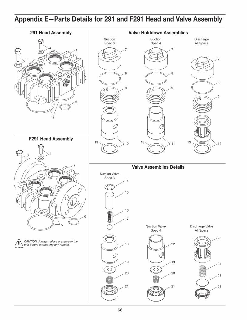
SuctionSpec 3
SuctionSpec 4
DischargeAll Specs
Suction ValveSpec 3
Suction ValveSpec 4
Discharge ValveAll Specs
7
9
8
7
9
8
13 1313
7
9
8
121110
14
15
16
17
18
19
20
21
22
19
20
21
23
24
25
26
3
1
6
5
4
2
3
6
5
4
Valve Holddown Assemblies291 Head Assembly
F291 Head Assembly
Valve Assemblies Details
Appendix E—Parts Details for 291 and F291 Head and Valve Assembly
WARNING
CAUTION: Always relieve pressure in the unit before attempting any repairs.
Model 291 and F291
66
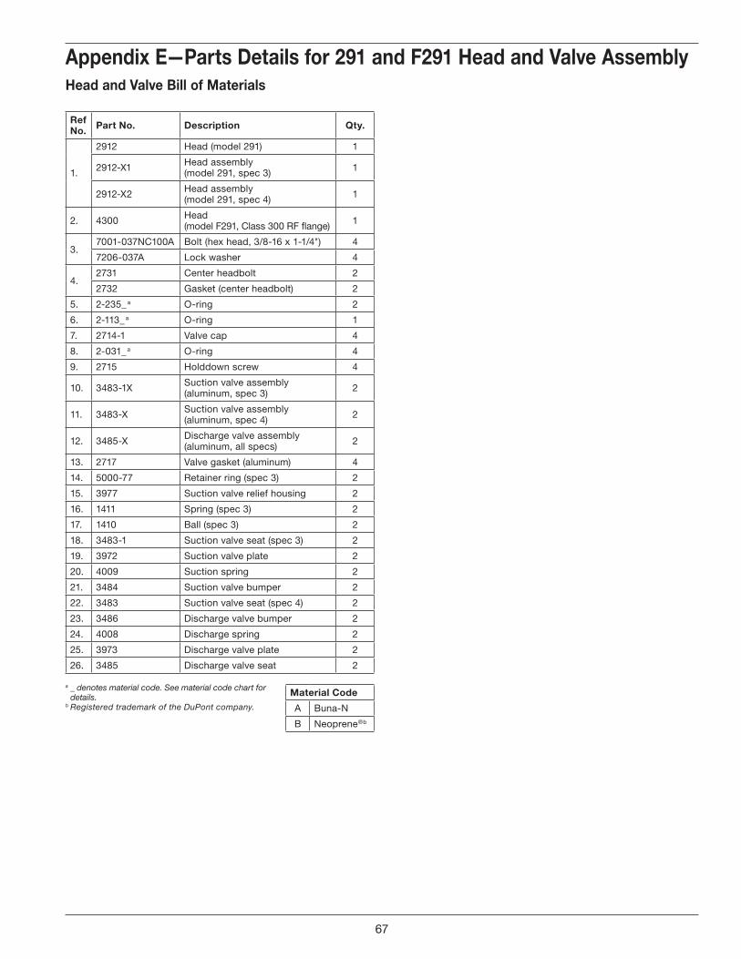
Appendix E—Parts Details for 291 and F291 Head and Valve AssemblyHead and Valve Bill of Materials
Ref No . Part No . Description Qty .
1.
2912 Head (model 291) 1
2912-X1 Head assembly (model 291, spec 3) 1
2912-X2 Head assembly (model 291, spec 4) 1
2. 4300 Head (model F291, Class 300 RF flange) 1
3.7001-037NC100A Bolt (hex head, 3/8-16 x 1-1/4") 4
7206-037A Lock washer 4
4.2731 Center headbolt 2
2732 Gasket (center headbolt) 2
5. 2-235_ a O-ring 2
6. 2-113_ a O-ring 1
7. 2714-1 Valve cap 4
8. 2-031_ a O-ring 4
9. 2715 Holddown screw 4
10. 3483-1X Suction valve assembly (aluminum, spec 3) 2
11. 3483-X Suction valve assembly (aluminum, spec 4) 2
12. 3485-X Discharge valve assembly (aluminum, all specs) 2
13. 2717 Valve gasket (aluminum) 4
14. 5000-77 Retainer ring (spec 3) 2
15. 3977 Suction valve relief housing 2
16. 1411 Spring (spec 3) 2
17. 1410 Ball (spec 3) 2
18. 3483-1 Suction valve seat (spec 3) 2
19. 3972 Suction valve plate 2
20. 4009 Suction spring 2
21. 3484 Suction valve bumper 2
22. 3483 Suction valve seat (spec 4) 2
23. 3486 Discharge valve bumper 2
24. 4008 Discharge spring 2
25. 3973 Discharge valve plate 2
26. 3485 Discharge valve seat 2
a _ denotes material code. See material code chart for details.
b Registered trademark of the DuPont company.
Material Code
A Buna-N
B Neoprene ®b
67
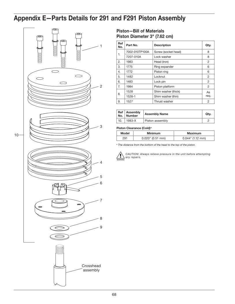
5
6
7
8
9
Crossheadassembly
4
3
2
1
10
Appendix E—Parts Details for 291 and F291 Piston Assembly
Piston—Bill of MaterialsPiston Diameter 3" (7 .62 cm)Ref No . Part No . Description Qty .
1.7002-010TP100A Screw (socket head) 8
7207-010A Lock washer 8
2. 1983 Head (iron) 2
3. 1775 Ring expander 6
4. 1772 Piston ring 6
5. 1482 Locknut 2
6. 1483 Lock pin 2
7. 1984 Piston platform 2
8.1528 Shim washer (thick) As
req.1528-1 Shim washer (thin)
9. 1527 Thrust washer 2
RefNo .
Assembly Number Assembly Name Qty .
10. 1983-X Piston assembly 2
Piston Clearance (Cold) a
Model Minimum Maximum
291 0.020" (0.51 mm) 0.044" (1.12 mm)
a The distance from the bottom of the head to the top of the piston.
WARNING
CAUTION: Always relieve pressure in the unit before attempting any repairs.
68
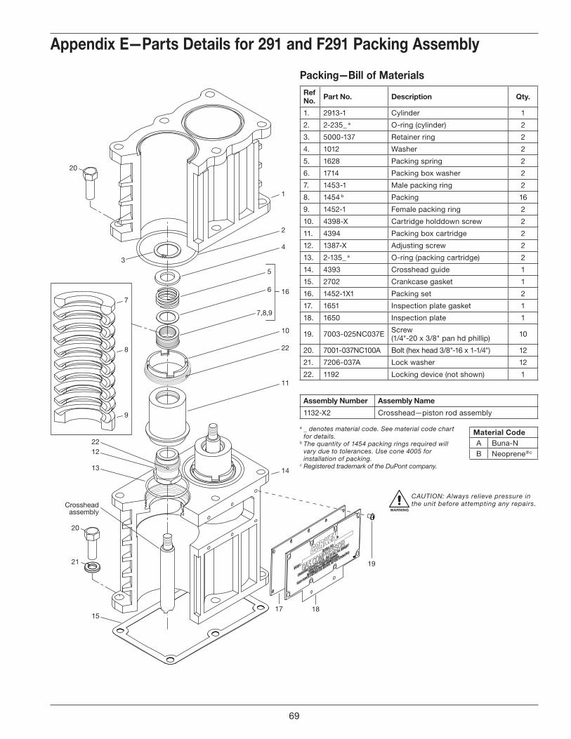
1
2
4
22
5
6 16
10
11
3
13
Crossheadassembly
1222
15
21
20
14
7
8
9
7,8,9
17 18
19
20
Appendix E—Parts Details for 291 and F291 Packing Assembly
Packing—Bill of MaterialsRef No . Part No . Description Qty .
1. 2913-1 Cylinder 1
2. 2-235_ a O-ring (cylinder) 2
3. 5000-137 Retainer ring 2
4. 1012 Washer 2
5. 1628 Packing spring 2
6. 1714 Packing box washer 2
7. 1453-1 Male packing ring 2
8. 1454 b Packing 16
9. 1452-1 Female packing ring 2
10. 43 98-X Cartridge holddown screw 2
11. 4394 Packing box cartridge 2
12. 1387-X Adjusting screw 2
13. 2-135_ a O-ring (packing cartridge) 2
14. 4393 Crosshead guide 1
15. 2702 Crankcase gasket 1
16. 1452-1X1 Packing set 2
17. 1651 Inspection plate gasket 1
18. 1650 Inspection plate 1
19. 7003-025NC037E Screw (1/4"-20 x 3/8" pan hd phillip) 10
20. 7001-037NC100A Bolt (hex head 3/8"-16 x 1-1/4") 12
21. 7206-037A Lock washer 12
22. 1192 Locking device (not shown) 1
Assembly Number Assembly Name
1132-X2 Crosshead—piston rod assembly
a _ denotes material code. See material code chart for details.
b The quantity of 1454 packing rings required will vary due to tolerances. Use cone 4005 for installation of packing.
c Registered trademark of the DuPont company.
Material CodeA Buna-NB Neoprene ®c
WARNING
CAUTION: Always relieve pressure in the unit before attempting any repairs.
69
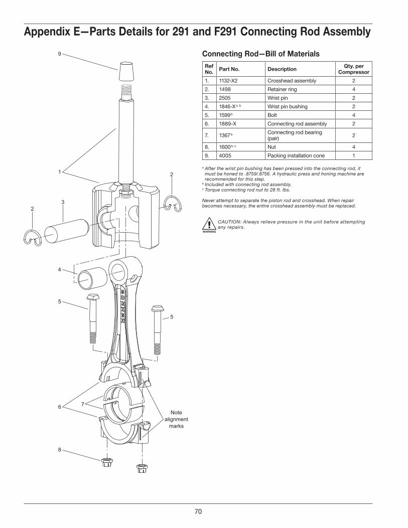
5
1
4
2
5
8
6
3
2
Notealignment
marks
7
9
Appendix E—Parts Details for 291 and F291 Connecting Rod Assembly
Connecting Rod—Bill of MaterialsRef No . Part No . Description Qty . per
Compressor
1. 1132-X2 Crosshead assembly 2
2. 1498 Retainer ring 4
3. 2505 Wrist pin 2
4. 1846-X a, b Wrist pin bushing 2
5. 1599 b Bolt 4
6. 1889-X Connecting rod assembly 2
7. 1367 b Connecting rod bearing (pair) 2
8. 1600 b, c Nut 4
9. 4005 Packing installation cone 1
a After the wrist pin bushing has been pressed into the connecting rod, it must be honed to .8759/.8756. A hydraulic press and honing machine are recommended for this step.
b Included with connecting rod assembly.c Torque connecting rod nut to 28 ft. lbs.
Never attempt to separate the piston rod and crosshead. When repair becomes necessary, the entire crosshead assembly must be replaced.
WARNING
CAUTION: Always relieve pressure in the unit before attempting any repairs.
70

1
Back Side
Front Side
1
2
22
2
2
22
Appendix E—Parts Details for 291 and F291 Flywheel Assembly
Flywheel—Bill of MaterialsRef No . Part No . Description Qty .
1. 2549 Flywheel (16" O.D., 3 groove) 1
2. H SF-1.250 Hub with three bolts and lockwashers 1
Assembly Number Assembly Name
2549-X1 Flywheel assembly (flywheel, hub, and three bolts)—standard
3271-X1 Flywheel assembly for extended crankshaft—optional
71
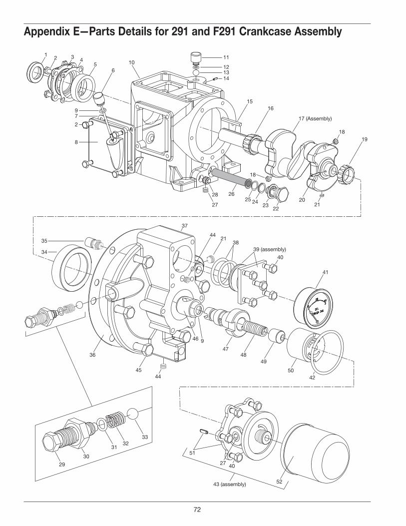
12 43
56
15
2625 24
2322
2120
10
18
28
27
16
17 (Assembly)
1819
37
2144
3839 (assembly)
40
41
79
11
121314
2
8
35
34
45
36
44
47
46 9
4849
5042
51
27 40
43 (assembly) 52
29
30
3132
33
a Not shown.b _ denotes material code. See material code chart for details.c Optional. d Registered trademark of the DuPont company.
Appendix E—Parts Details for 291 and F291 Crankcase Assembly
72
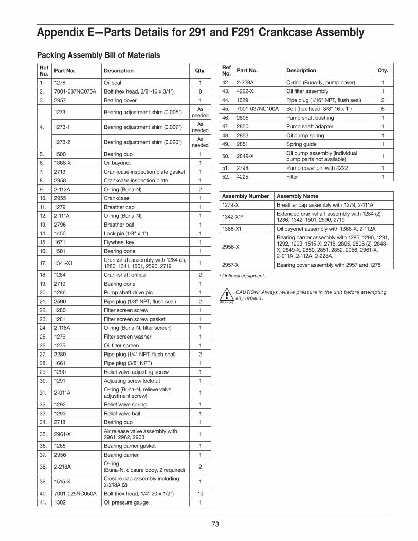
Appendix E—Parts Details for 291 and F291 Crankcase Assembly
Packing Assembly Bill of MaterialsRef No . Part No . Description Qty .
1. 1278 Oil seal 1
2. 7001-037NC075A Bolt (hex head, 3/8"-16 x 3/4") 8
3. 2957 Bearing cover 1
4.
1273 Bearing adjustment shim (0.005") As needed
1273-1 Bearing adjustment shim (0.007") As needed
1273-2 Bearing adjustment shim (0.020") As needed
5. 1500 Bearing cup 1
6. 1368-X Oil bayonet 1
7. 2713 Crankcase inspection plate gasket 1
8. 2958 Crankcase inspection plate 1
9. 2-112A O-ring (Buna-N) 2
10. 2955 Crankcase 1
11. 1279 Breather cap 1
12. 2-111A O-ring (Buna-N) 1
13. 2796 Breather ball 1
14. 1450 Lock pin (1/8" x 1") 1
15. 1671 Flywheel key 1
16. 1501 Bearing cone 1
17. 1341-X1 Crankshaft assembly with 1284 (2), 1286, 1341, 1501, 2590, 2719 1
18. 1284 Crankshaft orifice 2
19. 2719 Bearing cone 1
20. 1286 Pump shaft drive pin 1
21. 2590 Pipe plug (1/8" NPT, flush seal) 2
22. 1280 Filter screen screw 1
23. 1281 Filter screen screw gasket 1
24. 2-116A O-ring (Buna-N, filter screen) 1
25. 1276 Filter screen washer 1
26. 1275 Oil filter screen 1
27. 3289 Pipe plug (1/4" NPT, flush seal) 2
28. 1661 Pipe plug (3/8" NPT) 1
29. 1290 Relief valve adjusting screw 1
30. 1291 Adjusting screw locknut 1
31. 2-011A O-ring (Buna-N, relieve valve adjustment screw) 1
32. 1292 Relief valve spring 1
33. 1293 Relief valve ball 1
34. 2718 Bearing cup 1
35. 2961-X Air release valve assembly with 2961, 2962, 2963 1
36. 1285 Bearing carrier gasket 1
37. 2956 Bearing carrier 1
38. 2-218A O-ring (Buna-N, closure body, 2 required) 2
39. 1515-X Closure cap assembly including 2-218A (2) 1
40. 7001-025NC050A Bolt (hex head, 1/4"-20 x 1/2") 10
41. 1302 Oil pressure gauge 1
Ref No . Part No . Description Qty .
42. 2-228A O-ring (Buna-N, pump cover) 1
43. 4222-X Oil filter assembly 1
44. 1629 Pipe plug (1/16" NPT, flush seal) 2
45. 7001-037NC100A Bolt (hex head, 3/8"-16 x 1") 6
46. 2805 Pump shaft bushing 1
47. 2850 Pump shaft adapter 1
48. 2852 Oil pump spring 1
49. 2851 Spring guide 1
50. 2849-X Oil pump assembly (individual pump parts not available) 1
51. 2798 Pump cover pin with 4222 1
52. 4225 Filter 1
Assembly Number Assembly Name
1279-X Breather cap assembly with 1279, 2-111A
1342-X1 a Extended crankshaft assembly with 1284 (2), 1286, 1342, 1501, 2590, 2719
1368-X1 Oil bayonet assembly with 1368-X, 2-112A
2956-X
Bearing carrier assembly with 1285, 1290, 1291, 1292, 1293, 1515-X, 2718, 2805, 2806 (2), 2848-X, 2849-X, 2850, 2851, 2852, 2956, 2961-X, 2-011A, 2-112A, 2-228A.
2957-X Bearing cover assembly with 2957 and 1278
a Optional equipment.
WARNING
CAUTION: Always relieve pressure in the unit before attempting any repairs.
73
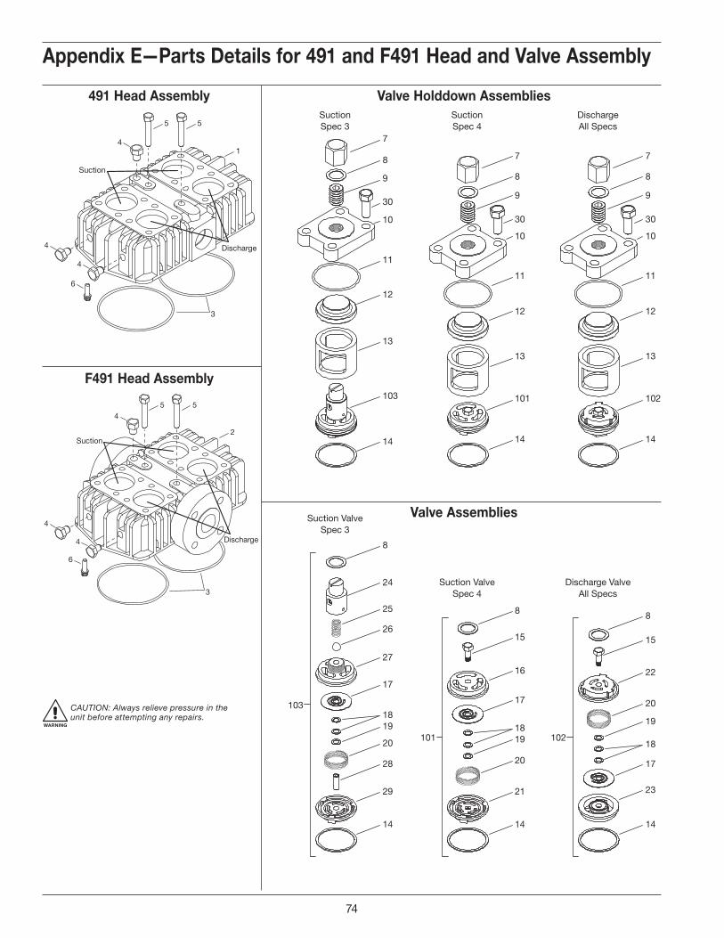
7
8
9
30
10
11
12
13
103
14
8
24
25
26
27
17
18103
19 1819 18
19
20
28
29
14
8
15
16
17
20
21
14
8
15
22
20
17
23
14
7
8
9
30
10
11
12
13
101
14
7
8
9
30
10
11
12
13
102
14
SuctionSpec 3
SuctionSpec 4
DischargeAll Specs
Suction ValveSpec 3
Suction ValveSpec 4
Discharge ValveAll Specs
101 102
5
4
Suction
Discharge4
4
6
5
1
3
5
Suction
Discharge
6
5
2
3
4
4
4
Valve Holddown Assemblies491 Head Assembly
F491 Head Assembly
Valve Assemblies
Appendix E—Parts Details for 491 and F491 Head and Valve Assembly
WARNING
CAUTION: Always relieve pressure in the unit before attempting any repairs.
Model 491 and F491
74
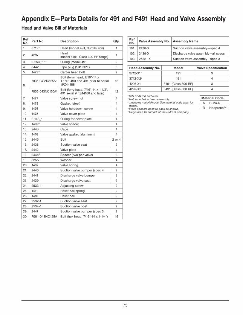
Appendix E—Parts Details for 491 and F491 Head and Valve AssemblyHead and Valve Bill of Materials
Ref No . Part No . Description Qty .
1. 3712 a Head (model 491, ductile iron) 1
2. 4297 Head (model F491, Class 300 RF flange) 1
3. 2-253_ a, b, c O-ring (model 491) 2
4. 3442 Pipe plug (1/4" NPT) 3
5. 1479 b Center head bolt 2
6.7005-043NC125A b
Bolt (ferry head, 7/16"-14 x 1-1/4", 490 and 491 prior to serial #FZ44188)
12
7005-043NC150A b Bolt (ferry head, 7/16"-14 x 1-1/2", 491 serial # FZ44188 and later) 12
7. 1477 Valve screw nut 4
8. 1478 Gasket (steel) 4
9. 1476 Valve holddown screw 4
10. 1475 Valve cover plate 4
11. 2-143_ c O-ring for cover plate 4
12. 1409 d Valve spacer 4
13. 2448 Cage 4
14. 1418 Valve gasket (aluminum) 4
15. 2446 Bolt 2 or 4
16. 2438 Suction valve seat 2
17. 2442 Valve plate 4
18. 2445 d Spacer (two per valve) 8
19. 3355 Washer 4
20. 1407 Valve spring 4
21. 2440 Suction valve bumper (spec 4) 2
22. 2441 Discharge valve bumper 2
23. 2439 Discharge valve seat 2
24. 2533-1 Adjusting screw 2
25. 1411 Relief ball spring 2
26. 1410 Relief ball 2
27. 2532-1 Suction valve seat 2
28. 2534-1 Suction valve post 2
29. 2447 Suction valve bumper (spec 3) 2
30. 7001-043NC125A Bolt (hex head, 7/16"-14 x 1-1/4") 16
Ref No . Valve Assembly No . Assembly Name
101. 2438-X Suction valve assembly—spec 4
102. 2439-X Discharge valve assembly—all specs
103. 2532-1X Suction valve assembly—spec 3
Head Assembly No . Model Valve Specification
3712-X1 a 491 3
3712-X2 a 491 4
4297-X1 F491 (Class 300 RF) 3
4297-X2 F491 (Class 300 RF) 4
a S/N FZ44188 and later.b Not included in head assembly.c _ denotes material code. See material code chart for
details.d Place spacers back to back as shown.e Registered trademark of the DuPont company.
Material Code
A Buna-N
B Neoprene ®e
75

5
6
7
8
9
Crossheadassembly
4
10
3
2
1
Appendix E—Parts Details for 491 and F491 Piston Assembly
Piston—Bill of MaterialsPiston Diameter 4" (10 .16 cm)Ref No . Part No . Description Qty .
1.7002-025TP125A Screw (socket head) 16
7207-025A Lock washer 16
2. 1985 Head (iron) 2
3. 1776 Ring expander 6
4. 1773 Piston ring 6
5. 1482 Locknut 2
6. 1483 Lock pin 2
7. 1986 Piston platform 2
8.1528 Shim washer (thick) As
Req.1528-1 Shim washer (thin)
9. 1527 Thrust washer 2
RefNo .
Assembly Number Assembly Name Qty .
10. 1985-X Piston assembly 2
Piston Clearance (Cold) a
Model Minimum Maximum
491 b 0.020" (0.51 mm) 0.044" (1.12 mm)
a The distance from the bottom of the head to the top of the piston.b For 491 compressor with head O-rings.
WARNING
CAUTION: Always relieve pressure in the unit before attempting any repairs.
76
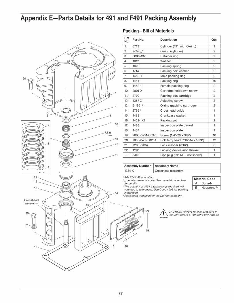
7
8
9
1
4
16
10
11
32
13
Crossheadassembly
12
15
14
5
6
7,8,9
17 18
19
21
20
20
22
22
Appendix E—Parts Details for 491 and F491 Packing Assembly
Packing—Bill of MaterialsRef No . Part No . Description Qty .
1. 3713 a Cylinder (491 with O-ring) 1
2. 2-243_ b O-ring (cylinder) 2
3. 5000-137 Retainer ring 2
4. 1012 Washer 2
5. 1628 Packing spring 2
6. 1714 Packing box washer 2
7. 1453-1 Male packing ring 2
8. 1454 c Packing ring 16
9. 1452-1 Female packing ring 2
10. 2801-X Cartridge holddown screw 2
11. 2799 Packing box cartridge 2
12. 1387-X Adjusting screw 2
13. 2-139_ b O-ring (packing cartridge) 2
14. 2765 d Crosshead guide 1
15. 1489 Crankcase gasket 1
16. 1452-1X1 Packing set 2
17. 1488 Inspection plate gasket 1
18. 1487 Inspection plate 1
19. 7003-025NC037E Screw (1/4"-20 x 3/8") 10
20. 7005-043NC125A Bolt (ferry head, 7/16"-14 x 1-1/4") 12
21. 7206-043A Lock washer (7/16") 6
22. 1192 Locking device (not shown) 1
— 3442 Pipe plug (1/4" NPT, not shown) 1
Assembly Number Assembly Name
1384-X Crosshead assembly
a S/N FZ44188 and later.b _ denotes material code. See material code chart
for details.c The quantity of 1454 packing rings required will
vary due to tolerances. Use Cone 4005 for packing installation.
d Registered trademark of the DuPont company.
Material CodeA Buna-NB Neoprene ®d
WARNING
CAUTION: Always relieve pressure in the unit before attempting any repairs.
77

5
1
9
4
2
5
8
6
3
2
Notealignment
marks
7
Appendix E—Parts Details for 491 and F491 Connecting Rod Assembly
Connecting Rod—Bill of MaterialsRef No . Part No . Description Qty . per
Compressor
1. 1384-X Crosshead assembly 2
2. 1498 Retainer ring 4
3. 1496 Wrist pin 2
4. 1495-X a, b Wrist pin bushing 2
5. 1492 b Bolt 4
6. 1490-X Connecting rod assembly 2
7. 1491 b Connecting rod bearing (pair) 2
8. 1493 b, c Nut 4
9. 4005 Packing installation cone 1
a After the wrist pin bushing has been pressed into the connecting rod, it must be honed to .8759/.8756. A hydraulic press and honing machine are recommended for this step.
b Included with connecting rod assembly.c Torque connecting rod nut to 30 ft. lbs.
Never attempt to separate the piston rod and crosshead. When repair becomes necessary, the entire crosshead assembly must be replaced.
WARNING
CAUTION: Always relieve pressure in the unit before attempting any repairs.
78
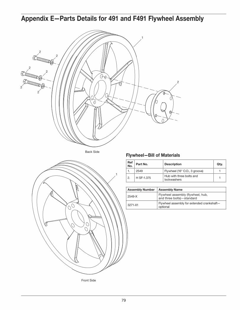
1
1
2
22
2
2
22
Back Side
Front Side
Appendix E—Parts Details for 491 and F491 Flywheel Assembly
Flywheel—Bill of MaterialsRef No . Part No . Description Qty .
1. 2549 Flywheel (16" O.D., 3 groove) 1
2. H SF-1.375 Hub with three bolts and lockwashers 1
Assembly Number Assembly Name
2549-X Flywheel assembly (flywheel, hub, and three bolts)—standard
3271-X1 Flywheel assembly for extended crankshaft—optional
79

1 23
45
6
10 11
121314
1516
17
18
19
18
212026
25 2423
22
28
27
35
34
37
2144
3839 (assembly)
40
41
45
36
44
4748
49
5042
46 9
51
2740
43 (assembly) 52
29
30
3132
33
79
2-1
8
Appendix E—Parts Details for 491 and F491 Crankcase Assembly
80
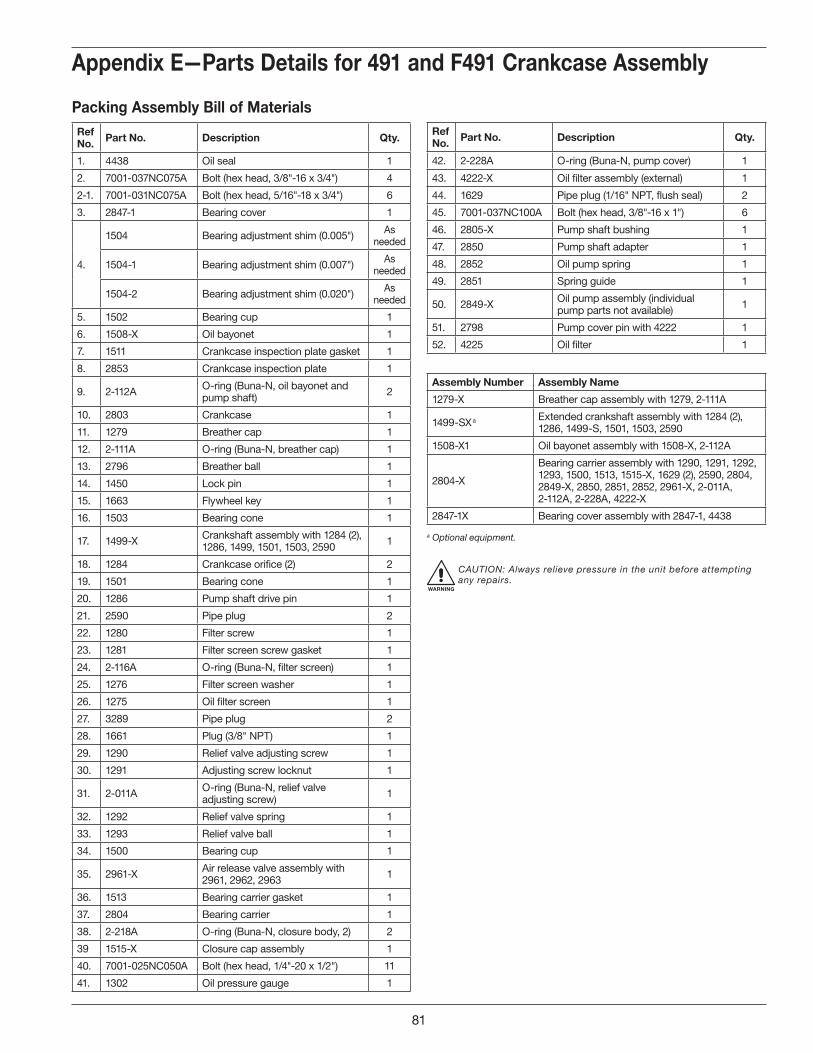
Appendix E—Parts Details for 491 and F491 Crankcase Assembly
Packing Assembly Bill of MaterialsRef No . Part No . Description Qty .
1. 4438 Oil seal 1
2. 7001-037NC075A Bolt (hex head, 3/8"-16 x 3/4") 4
2-1. 7001-031NC075A Bolt (hex head, 5/16"-18 x 3/4") 6
3. 2847-1 Bearing cover 1
4.
1504 Bearing adjustment shim (0.005") As needed
1504-1 Bearing adjustment shim (0.007") As needed
1504-2 Bearing adjustment shim (0.020") As needed
5. 1502 Bearing cup 1
6. 1508-X Oil bayonet 1
7. 1511 Crankcase inspection plate gasket 1
8. 2853 Crankcase inspection plate 1
9. 2-112A O-ring (Buna-N, oil bayonet and pump shaft) 2
10. 2803 Crankcase 1
11. 1279 Breather cap 1
12. 2-111A O-ring (Buna-N, breather cap) 1
13. 2796 Breather ball 1
14. 1450 Lock pin 1
15. 1663 Flywheel key 1
16. 1503 Bearing cone 1
17. 1499-X Crankshaft assembly with 1284 (2), 1286, 1499, 1501, 1503, 2590 1
18. 1284 Crankcase orifice (2) 2
19. 1501 Bearing cone 1
20. 1286 Pump shaft drive pin 1
21. 2590 Pipe plug 2
22. 1280 Filter screw 1
23. 1281 Filter screen screw gasket 1
24. 2-116A O-ring (Buna-N, filter screen) 1
25. 1276 Filter screen washer 1
26. 1275 Oil filter screen 1
27. 3289 Pipe plug 2
28. 1661 Plug (3/8" NPT) 1
29. 1290 Relief valve adjusting screw 1
30. 1291 Adjusting screw locknut 1
31. 2-011A O-ring (Buna-N, relief valve adjusting screw) 1
32. 1292 Relief valve spring 1
33. 1293 Relief valve ball 1
34. 1500 Bearing cup 1
35. 2961-X Air release valve assembly with 2961, 2962, 2963 1
36. 1513 Bearing carrier gasket 1
37. 2804 Bearing carrier 1
38. 2-218A O-ring (Buna-N, closure body, 2) 2
39 1515-X Closure cap assembly 1
40. 7001-025NC050A Bolt (hex head, 1/4"-20 x 1/2") 11
41. 1302 Oil pressure gauge 1
Ref No . Part No . Description Qty .
42. 2-228A O-ring (Buna-N, pump cover) 1
43. 4222-X Oil filter assembly (external) 1
44. 1629 Pipe plug (1/16" NPT, flush seal) 2
45. 7001-037NC100A Bolt (hex head, 3/8"-16 x 1") 6
46. 2805-X Pump shaft bushing 1
47. 2850 Pump shaft adapter 1
48. 2852 Oil pump spring 1
49. 2851 Spring guide 1
50. 2849-X Oil pump assembly (individual pump parts not available) 1
51. 2798 Pump cover pin with 4222 1
52. 4225 Oil filter 1
Assembly Number Assembly Name
1279-X Breather cap assembly with 1279, 2-111A
1499-SX a Extended crankshaft assembly with 1284 (2), 1286, 1499-S, 1501, 1503, 2590
1508-X1 Oil bayonet assembly with 1508-X, 2-112A
2804-X
Bearing carrier assembly with 1290, 1291, 1292, 1293, 1500, 1513, 1515-X, 1629 (2), 2590, 2804, 2849-X, 2850, 2851, 2852, 2961-X, 2-011A, 2-112A, 2-228A, 4222-X
2847-1X Bearing cover assembly with 2847-1, 4438
a Optional equipment.
WARNING
CAUTION: Always relieve pressure in the unit before attempting any repairs.
81

10
11
12
18
19
2021
22
23
24
25
26
27
28
31
30
24
25104
26
27
29
13
14
15
16
101
17
10
11
12
13
14
15
16
102
17
101
102 103
10
11
12
13
14
15
16
103
17
17 17 17
SuctionSpec 3
SuctionSpec 4
DischargeAll Specs
Suction ValveSpec 3
Suction ValveSpec 4
Discharge ValveAll Specs
29
30
26
27104
24
25
31
104
9
7
4
5
6
15
7
3
8
82
9
6
Valve Holddown Assemblies691 Head Assembly
Valve Assemblies
F691 Head Assembly
Appendix E—Parts Details for 691 and F691 Head and Valve Assembly
WARNING
CAUTION: Always relieve pressure in the unit before attempting any repairs.
Model 691 and F691
82
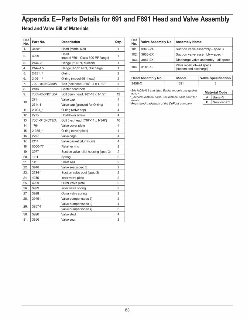
Appendix E—Parts Details for 691 and F691 Head and Valve AssemblyHead and Valve Bill of Materials
Ref No . Part No . Description Qty .
1. 3458 a Head (model 691) 1
2. 4299 Head (model F691, Class 300 RF flange) 1
3. 2144-2 Flange (2" NPT, suction) 1
4. 2144-1.5 Flange (1-1/2" NPT, discharge) 1
5. 2-231_ b O-ring 2
6. 2-261_ b O-ring (model 691 head) 2
7. 7001-043NC150A Bolt (hex head, 7/16"-14 x 1-1/2") 8
8. 2136 Center head bolt 2
9. 7005-050NC150A Bolt (ferry head, 1/2"-13 x 1-1/2") 12
10.2714 Valve cap 4
2714-1 Valve cap (grooved for O-ring) 4
11. 2-031_ b O-ring (valve cap) 4
12. 2715 Holddown screw 4
13. 7001-043NC137A Bolt (hex head, 7/16"-14 x 1-3/8") 16
14. 1764 Valve cover plate 4
15. 2-235_ b O-ring (cover plate) 4
16. 2797 Valve cage 4
17. 2114 Valve gasket (aluminum) 4
18. 5000-77 Retainer ring 2
19. 3977 Suction valve relief housing (spec 3) 2
20. 1411 Spring 2
21. 1410 Relief ball 2
22. 3948 Valve seat (spec 3) 2
23. 2534-1 Suction valve post (spec 3) 2
24. 4230 Inner valve plate 2
25. 4229 Outer valve plate 2
26. 3929 Inner valve spring 2
27. 3928 Outer valve spring 2
28. 3949-1 Valve bumper (spec 3) 2
29. 3857-1Valve bumper (spec 3) 4
Valve bumper (spec 4) 6
30. 3920 Valve stud 4
31. 3856 Valve seat 2
Ref No . Valve Assembly No . Assembly Name
101. 3948-2X Suction valve assembly—spec 3
102. 3856-2X Suction valve assembly—spec 4
103. 3857-2X Discharge valve assembly—all specs
104. 3146-X2 Valve repair kit—all specs (suction and discharge)
Head Assembly No . Model Valve Specification
3458-X 691 3
a S/N NQ51455 and later. Earlier models use gasket #2177.
b _ denotes material code. See material code chart for details.
c Registered trademark of the DuPont company.
Material Code
A Buna-N
B Neoprene ®c
83
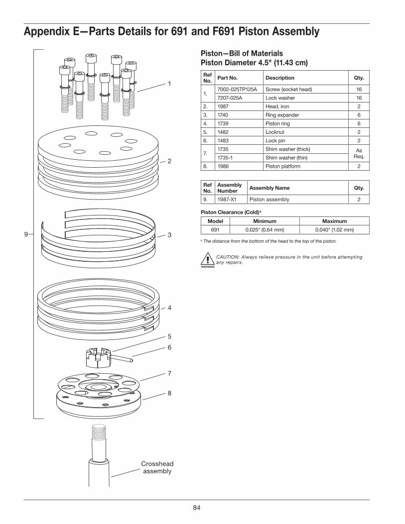
5
6
7
8
Crossheadassembly
4
39
2
1
Appendix E—Parts Details for 691 and F691 Piston Assembly
Piston—Bill of MaterialsPiston Diameter 4 .5" (11 .43 cm)Ref No . Part No . Description Qty .
1.7002-025TP125A Screw (socket head) 16
7207-025A Lock washer 16
2. 1987 Head, iron 2
3. 1740 Ring expander 6
4. 1739 Piston ring 6
5. 1482 Locknut 2
6. 1483 Lock pin 2
7.1735 Shim washer (thick) As
Req.1735-1 Shim washer (thin)
8. 1986 Piston platform 2
RefNo .
Assembly Number Assembly Name Qty .
9. 1987-X1 Piston assembly 2
Piston Clearance (Cold) a
Model Minimum Maximum
691 0.025" (0.64 mm) 0.040" (1.02 mm)
a The distance from the bottom of the head to the top of the piston.
WARNING
CAUTION: Always relieve pressure in the unit before attempting any repairs.
84

7
8
9
1
2
3
4
17
5
6
6
10
15
11
Crossheadassembly
13
12
16
24
23
14
7,8,9
18 19
20
23
22
21
Appendix E—Parts Details for 691 and F691 Packing Assembly
Packing—Bill of MaterialsRef No . Part No . Description Qty .
1. 3457 Cylinder (model 691) 1
2. 2-247_ a O-ring (cylinder) 2
3. 1749-X Cartridge holddown screw 2
4. 5000-175 Retainer ring 2
5. 1731 Packing spring 2
6. 1728 Packing washer 2
7. 1724 Male packing ring 2
8. 1725-2 Packing ring 8
9. 1723 Female packing ring 2
10. 2407 Packing box cartridge 2
11. 2-233_ a O-ring (packing cartridge) 2
12. 1748 Cartridge plate 2
13. 5000-350 Retainer ring 2
14. 2405 Crosshead guide 1
15. 1722-X Adjusting screw 2
16. 1761 Crankcase gasket 1
17. 1725-2X Packing set 2
18. 1760 Inspection plate gasket 1
19. 1721 Inspection plate 1
20. 7003-025NC037E Screw (1/4"-20 x 3/8") 10
21. 1192 Locking device (for adjusting screw, not shown) 2
22. 2893 Locking device cartridge holddown screw (not shown) 2
23. 7005-050NC175A Bolt 16
24. 7206-050A Lock washer 16
Assembly Number Assembly Name
2405-X Crosshead guide assembly with 1748 (2), 2405, 5000-350 (2)
3544-X4 Crosshead assembly “M” style
a _ denotes material code. See material code chart for details.
c The quantity of 1454 packing rings required will vary due to tolerances. Use Cone 4005 for packing installation.
d S/N XC30633 and later.e Registered trademark of the DuPont company.
Material Code
A Buna-N
B Neoprene ®d
WARNING
CAUTION: Always relieve pressure in the unit before attempting any repairs.
85
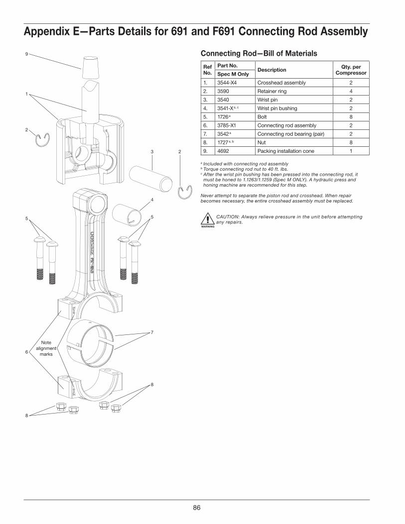
1
2
5
4
3
5
7
8
6
Notealignment
marks
8
2
9
Appendix E—Parts Details for 691 and F691 Connecting Rod Assembly
Connecting Rod—Bill of Materials
Ref No .
Part No .Description Qty . per
CompressorSpec M Only
1. 3544-X4 Crosshead assembly 2
2. 3590 Retainer ring 4
3. 3540 Wrist pin 2
4. 3541-X a, c Wrist pin bushing 2
5. 1726 a Bolt 8
6. 3785-X1 Connecting rod assembly 2
7. 3542 a Connecting rod bearing (pair) 2
8. 1727 a, b Nut 8
9. 4692 Packing installation cone 1
a Included with connecting rod assembly b Torque connecting rod nut to 40 ft. lbs.c After the wrist pin bushing has been pressed into the connecting rod, it
must be honed to 1.1263/1.1259 (Spec M ONLY). A hydraulic press and honing machine are recommended for this step.
Never attempt to separate the piston rod and crosshead. When repair becomes necessary, the entire crosshead assembly must be replaced.
WARNING
CAUTION: Always relieve pressure in the unit before attempting any repairs.
86

Back Side
Front Side
1
1
2
22
2
2
22
Appendix E—Parts Details for 691 and F691 Flywheel Assembly
Flywheel—Bill of MaterialsRef No . Part No . Description Qty .
1. 1762 Flywheel (19.5" O.D., 4 groove) 1
2. H E-2.125 Hub with three bolts and lockwashers 1
Assembly Number Assembly Name
1762-X Flywheel assembly (flywheel, hub,and three bolts)—standard
87

Appendix E—Parts Details for 691 and F691 Crankcase Assembly
1
2
3
5
6
9
3
29
52
2830
50
51
26
7
20
16
15
3637
38
4039
1413
1718
19
2122
2324
25
8
10
11
124
32
33
34
42
43
4445
4613
41
49
47
54
48
3531
57
32
5853
41
4
27
5348
56
Inside ofBearing Carrier
Pump Cover Oil/Filter Adapter
Oil Passage HoleImportant! Line up hole in
gasket with oil passage hole.
Pumpside of adapter shown forproper orientation of cover and
location of pump cover pin.
55
53
58
27
59(Includes all parts shown except #50 and #51)
88

Appendix E—Parts Details for 691 and F691 Crankcase Assembly
Packing—Bill of MaterialsRef No . Part No . Description Qty .
1. 1737 Bearing cone 1
2. 3638-1 Spacer 1
3. 1284 Crankshaft orifice 2
4. 2197 Drive pin 1
5. 2933 Link pin 1
6. 3786 Crankshaft 1
7. 3503 Flywheel key 1
8. 3580 Bearing cone 1
9. 3786-X1 Crankshaft assembly 1
10. 7001-031NC075A Bolt (hex head, 5/16"–18 x 3/4") 6
11. 2122 Inspection cover 1
12. 2123 Gasket (inspection cover) 1
13. 2-112A O-ring, Buna-N 2
14. 3225-X1 Oil bayonet assembly (with O-ring) 1
15. 2126 Breather ball 1
16. 3579 Bearing cup 1
17.
3589 Bearing adjustment shim (.005") As needed
3589-1 Bearing adjustment shim (.007") As needed
3589-2 Bearing adjustment shim (.020") As needed
18. 3539 Bearing cover 1
19. 3526 Oil seal 1
20. 1280 Filter screw 1
21. 1281 Gasket (filter) 1
22. 2-116A O-ring (Buna-N) 1
23. 1276 Washer 1
24. 1275 Oil filter screen 1
25. 3443 Pipe plug (1/2" NPT, steel) 1
26. 3221 Crankcase 1
27. 7001-037NC100A Bolt (hex head, 3/8"–16 x 1", grade 5) 12
28. 3875 Access cover 1
29. 7003-025NC037E Screw (1/4"–20 x 3/8") 4
30. 3874 Gasket, access cover 1
31. 1515-X Closure cap assembly 1
32. 7001-025NC050A Bolt (hex head, 1/4"–20 x 1/2") 11
33. 1515 Closure cap 1
34. 1516 Closure body 1
35. 2-218A O-ring (Buna-N) 2
36. 1290 Relief valve adjusting screw 1
37. 2-011A O-ring (Buna-N) 1
38. 1291 Adjusting screw locknut 1
39. 1292 Relief valve spring 1
40. 1293 Relief valve ball 1
41. 4222-X a Oil filter adapter assembly (with pin) 1
42. 2-228A O-ring (Buna-N) 1
43. 2849-1X a Oil pump assembly 1
Ref No . Part No . Description Qty .
44. 2851 Spring guide 1
45. 2852 Oil pump spring 1
46. 3219 Pump shaft adapter 1
47. 2805-X b Pump shaft bushing 1
48. 1629 Pipe plug (1/16" NPT, flush seal) 1
49. 1736 Bearing cup 1
50. 1302 Oil pressure gauge 1
51. 1044 Bushing (1/8" x 1/4" NPT) 1
52. 3220-2 Bearing carrier 1
53. 3289 Pipe plug (1/4" NPT, flush seal) 4
54. 2131 Bearing carrier gasket 1
55. 2961-X Air release valve assembly 1
56. 2590 Pipe plug (1/8" NPT, flush seal) 1
57. 4225 Filter 1
58. 2798 Pump cover pin (included with 4222-X) 1
59. 3220-2X Bearing carrier assembly M3 style 1
Assembly Number Assembly Name
3221-X1 Crankcase assembly (M3, 4, 8, 9) without lubrication (not shown)
a Caution: To avoid damage during assembly, refer to installation Instruction Manual IE400.
b Must be rebored and honed after replacing (0.876"/0.875" diameter).
WARNING
CAUTION: Always relieve pressure in the unit before attempting any repairs.
89
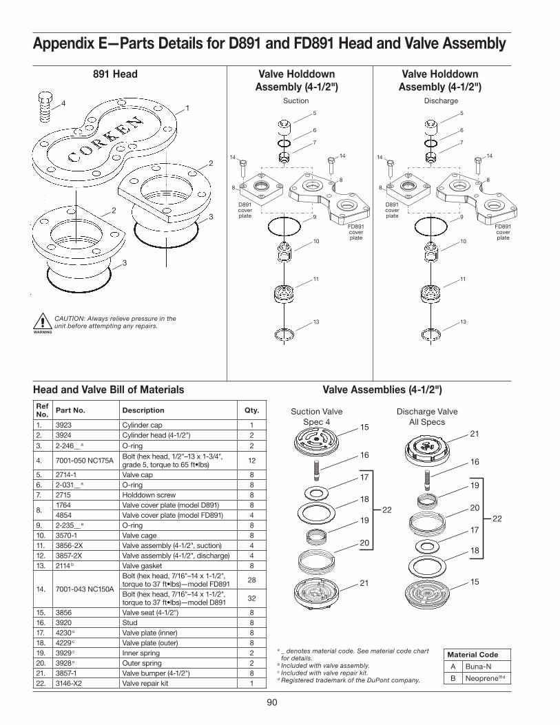
1
2
32
3
45
6
7
14
8
9
14
D891coverplate
FD891coverplate
8
10
11
13
5
6
7
14
8
9
14
D891coverplate
FD891coverplate
8
10
11
13
15
16
17
1822
19
20
21
Suction ValveSpec 4
Discharge ValveAll Specs
21
16
19
2022
17
18
15
Valve Assemblies (4-1/2")
891 Head Valve Holddown Assembly (4-1/2")
Valve Holddown Assembly (4-1/2")
DischargeSuction
Appendix E—Parts Details for D891 and FD891 Head and Valve Assembly
WARNING
CAUTION: Always relieve pressure in the unit before attempting any repairs.
Head and Valve Bill of MaterialsRef No . Part No . Description Qty .
1. 3923 Cylinder cap 12. 3924 Cylinder head (4-1/2") 23. 2-246__ a O-ring 2
4. 7001-050 NC175A Bolt (hex head, 1/2"–13 x 1-3/4", grade 5, torque to 65 ft•lbs) 12
5. 2714-1 Valve cap 86. 2-031__ a O-ring 87. 2715 Holddown screw 8
8.1764 Valve cover plate (model D891) 84854 Valve cover plate (model FD891) 4
9. 2-235__ a O-ring 810. 3570-1 Valve cage 811. 3856-2X Valve assembly (4-1/2", suction) 412. 3857-2X Valve assembly (4-1/2", discharge) 413. 2114 b Valve gasket 8
14. 7001-043 NC150A
Bolt (hex head, 7/16"–14 x 1-1/2", torque to 37 ft•lbs)—model FD891 28
Bolt (hex head, 7/16"–14 x 1-1/2", torque to 37 ft•lbs)—model D891 32
15. 3856 Valve seat (4-1/2") 816. 3920 Stud 817. 4230 c Valve plate (inner) 818. 4229 c Valve plate (outer) 819. 3929 c Inner spring 220. 3928 c Outer spring 221. 3857-1 Valve bumper (4-1/2") 822. 3146-X2 Valve repair kit 1
a _ denotes material code. See material code chart for details.
b Included with valve assembly.c Included with valve repair kit.d Registered trademark of the DuPont company.
Material Code
A Buna-N
B Neoprene ®d
Model D891 and FD891
90
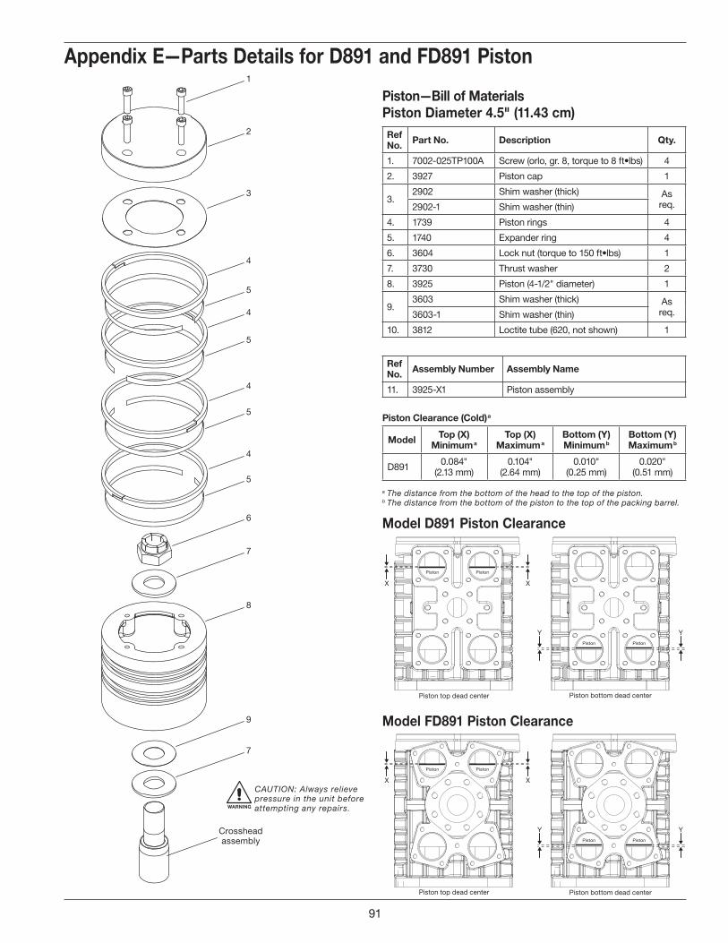
1
2
3
4
5
4
5
4
5
4
5
6
Crossheadassembly
7
8
9
7
Piston Piston
Piston
XX
YYPiston
Piston top dead center Piston bottom dead center
Piston Piston
XX
Piston top dead center Piston bottom dead center
Piston
YYPiston
Model D891 Piston Clearance
Model FD891 Piston Clearance
Appendix E—Parts Details for D891 and FD891 Piston
Piston—Bill of MaterialsPiston Diameter 4 .5" (11 .43 cm)Ref No . Part No . Description Qty .
1. 7002-025TP100A Screw (orlo, gr. 8, torque to 8 ft•lbs) 4
2. 3927 Piston cap 1
3.2902 Shim washer (thick) As
req.2902-1 Shim washer (thin)
4. 1739 Piston rings 4
5. 1740 Expander ring 4
6. 3604 Lock nut (torque to 150 ft•lbs) 1
7. 3730 Thrust washer 2
8. 3925 Piston (4-1/2" diameter) 1
9.3603 Shim washer (thick) As
req.3603-1 Shim washer (thin)
10. 3812 Loctite tube (620, not shown) 1
RefNo . Assembly Number Assembly Name
11. 3925-X1 Piston assembly
Piston Clearance (Cold) a
Model Top (X)Minimum a
Top (X) Maximum a
Bottom (Y) Minimum b
Bottom (Y) Maximum b
D891 0.084"(2.13 mm)
0.104"(2.64 mm)
0.010"(0.25 mm)
0.020"(0.51 mm)
a The distance from the bottom of the head to the top of the piston.b The distance from the bottom of the piston to the top of the packing barrel.
WARNING
CAUTION: Always relieve pressure in the unit before attempting any repairs.
91
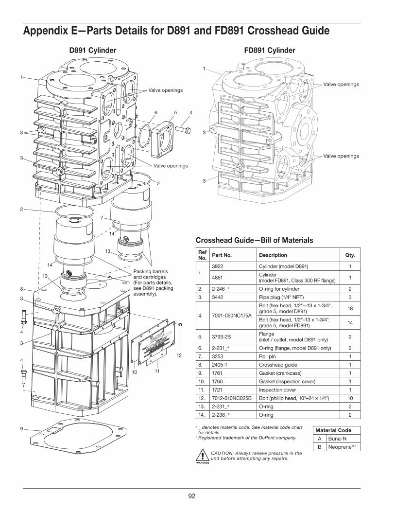
Appendix E—Parts Details for D891 and FD891 Crosshead Guide
Crosshead Guide—Bill of MaterialsRef No . Part No . Description Qty .
1.3922 Cylinder (model D891) 1
4851 Cylinder (model FD891, Class 300 RF flange) 1
2. 2-246_ a O-ring for cylinder 2
3. 3442 Pipe plug (1/4" NPT) 3
4. 7001-050NC175A
Bolt (hex head, 1/2"—13 x 1-3/4", grade 5, model D891) 18
Bolt (hex head, 1/2"–13 x 1-3/4", grade 5, model FD891) 14
5. 3793-2S Flange (inlet / outlet, model D891 only) 2
6. 2-231_ a O-ring (flange, model D891 only) 2
7. 3253 Roll pin 1
8. 2405-1 Crosshead guide 1
9. 1761 Gasket (crankcase) 1
10. 1760 Gasket (inspection cover) 1
11. 1721 Inspection cover 1
12. 7012-010NC025B Bolt (phillip head, 10"–24 x 1/4") 10
13. 2-231_ a O-ring 2
14. 2-238_ a O-ring 2
a _ denotes material code. See material code chart for details.
b Registered trademark of the DuPont company.
WARNING
CAUTION: Always relieve pressure in the unit before attempting any repairs.
Material Code
A Buna-N
B Neoprene ®b
13
Valve openings
2
6 5 4
Valve openings
7
1
3
2
3
3
8
4
3
4
9
14
14
13
10 11
12
Packing barrels and cartridges(For parts details, see D891 packing assembly).
Valve openings
Valve openings
3
1
3
D891 Cylinder FD891 Cylinder
92
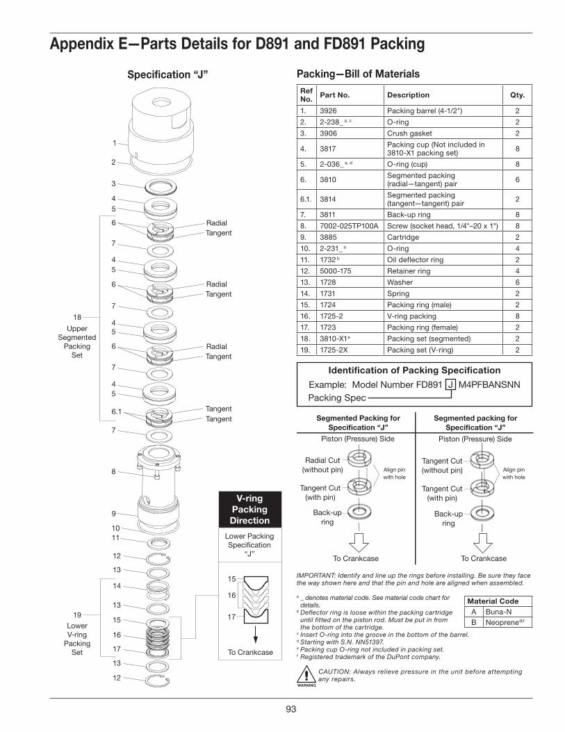
1
2
3
45
6
7
45
6
7
45
6
7
45
6.1
7
8
9
10
12
13
14
13
15
16
17
13
12
19
18
Lower PackingSpeci�cation
“J”
15
16
17
To Crankcase
RadialTangent
RadialTangent
RadialTangent
TangentTangent
UpperSegmented
PackingSet
LowerV-ring
PackingSet
11
V-ring Packing Direction
Appendix E—Parts Details for D891 and FD891 Packing
Specification “J” Packing—Bill of MaterialsRef No . Part No . Description Qty .
1. 3926 Packing barrel (4-1/2") 2
2. 2-238_ a, c O-ring 2
3. 3906 Crush gasket 2
4. 3817 Packing cup (Not included in 3810-X1 packing set) 8
5. 2-036_ a, d O-ring (cup) 8
6. 3810 Segmented packing(radial—tangent) pair 6
6.1. 3814 Segmented packing(tangent—tangent) pair 2
7. 3811 Back-up ring 8
8. 7002-025TP100A Screw (socket head, 1/4"–20 x 1") 8
9. 3885 Cartridge 2
10. 2-231_ a O-ring 4
11. 1732 b Oil deflector ring 2
12. 5000-175 Retainer ring 4
13. 1728 Washer 6
14. 1731 Spring 2
15. 1724 Packing ring (male) 2
16. 1725-2 V-ring packing 8
17. 1723 Packing ring (female) 2
18. 3810-X1 e Packing set (segmented) 2
19. 1725-2X Packing set (V-ring) 2
Identification of Packing Specification
Example: Model Number FD891 J M4PFBANSNN Packing Spec
To Crankcase
Piston (Pressure) Side
Radial Cut(without pin)
Segmented Packing forSpeci�cation “J”
Tangent Cut(with pin)
Back-upring
To Crankcase
Piston (Pressure) Side
Tangent Cut(without pin)
Segmented packing forSpeci�cation “J”
Tangent Cut(with pin)
Back-upring
Align pinwith hole
Align pinwith hole
IMPORTANT: Identify and line up the rings before installing. Be sure they face the way shown here and that the pin and hole are aligned when assembled.
a _ denotes material code. See material code chart for details.
b Deflector ring is loose within the packing cartridge until fitted on the piston rod. Must be put in from the bottom of the cartridge.
c Insert O-ring into the groove in the bottom of the barrel.d Starting with S.N. NN51397. e Packing cup O-ring not included in packing set.f Registered trademark of the DuPont company.
WARNING
CAUTION: Always relieve pressure in the unit before attempting any repairs.
Material CodeA Buna-NB Neoprene ®f
93
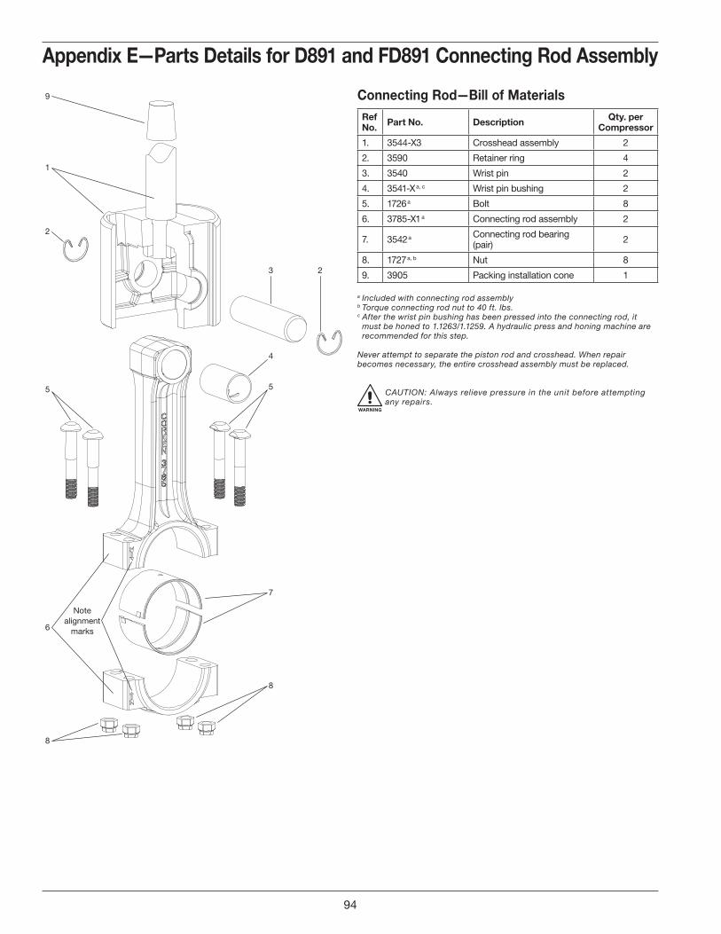
1
2
5
4
3
5
7
8
6
Notealignment
marks
8
2
9
Appendix E—Parts Details for D891 and FD891 Connecting Rod Assembly
Connecting Rod—Bill of MaterialsRef No . Part No . Description Qty . per
Compressor
1. 3544-X3 Crosshead assembly 2
2. 3590 Retainer ring 4
3. 3540 Wrist pin 2
4. 3541-X a, c Wrist pin bushing 2
5. 1726 a Bolt 8
6. 3785-X1 a Connecting rod assembly 2
7. 3542 a Connecting rod bearing (pair) 2
8. 1727 a, b Nut 8
9. 3905 Packing installation cone 1
a Included with connecting rod assemblyb Torque connecting rod nut to 40 ft. lbs.c After the wrist pin bushing has been pressed into the connecting rod, it
must be honed to 1.1263/1.1259. A hydraulic press and honing machine are recommended for this step.
Never attempt to separate the piston rod and crosshead. When repair becomes necessary, the entire crosshead assembly must be replaced.
WARNING
CAUTION: Always relieve pressure in the unit before attempting any repairs.
94
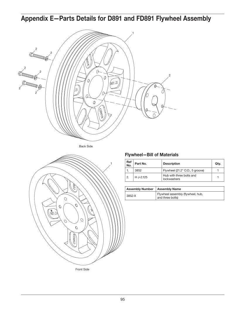
1
1
2
22
22
2
2
Back Side
Front Side
Appendix E—Parts Details for D891 and FD891 Flywheel Assembly
Flywheel—Bill of MaterialsRef No . Part No . Description Qty .
1. 3852 Flywheel (21.2" O.D., 5 groove) 1
2. H J-2.125 Hub with three bolts and lockwashers 1
Assembly Number Assembly Name
3852-X Flywheel assembly (flywheel, hub, and three bolts)
95
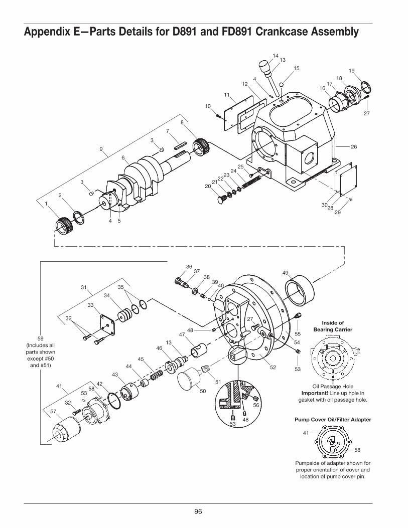
Appendix E—Parts Details for D891 and FD891 Crankcase Assembly
1
2
3
5
6
9
3
29
52
2830
50
51
26
7
20
16
15
3637
38
4039
1413
1718
19
2122
2324
25
8
10
11
124
32
33
34
42
43
4445
4613
41
49
47
54
48
3531
57
32
5853
41
4
27
5348
56
Inside ofBearing Carrier
Pump Cover Oil/Filter Adapter
Oil Passage HoleImportant! Line up hole in
gasket with oil passage hole.
Pumpside of adapter shown forproper orientation of cover and
location of pump cover pin.
55
53
58
27
59(Includes all parts shown except #50 and #51)
96

Appendix E—Parts Details for D891 and FD891 Crankcase Assembly
Packing Assembly Bill of MaterialsRef No . Part No . Description Qty .
1. 1737 Bearing cone 1
2. 3638-1 Spacer 1
3. 1284 Crankshaft orifice 2
4. 2197 Drive pin 1
5. 2933 Link pin 1
6. 3786 Crankshaft 1
7. 3503 Flywheel key 1
8. 3580 Bearing cone 1
9. 3786-X1 Crankshaft assembly 1
10. 7001-031NC075A Bolt (hex head, 5/16"–18 x 3/4") 6
11. 2122 Inspection cover 1
12. 2123 Gasket (inspection cover) 1
13. 2-112A O-ring (Buna-N) 2
14. 3225-X1 Oil bayonet assembly (with O-ring) 1
15. 2126 Breather ball 1
16. 3579 Bearing cup 1
17.
3589 Bearing adjustment shim (.005") As needed
3589-1 Bearing adjustment shim (.007") As needed
3589-2 Bearing adjustment shim (.020") As needed
18. 3539 Bearing cover 1
19. 3526 Oil seal 1
20. 1280 Filter screw 1
21. 1281 Gasket (filter) 1
22. 2-116A O-ring (Buna-N) 1
23. 1276 Washer 1
24. 1275 Oil filter screen 1
25. 3443 Pipe plug (1/2" NPT, steel) 1
26. 3221 Crankcase 1
27. 7001-037NC100A Bolt (hex head, 3/8"–16 x 1", grade 5) 12
28. 3875 Access cover 1
29. 7003-025NC037E Screw (1/4"–20 x 3/8") 4
30. 3874 Gasket (access cover) 1
31. 1515-X Closure cap assembly 1
32. 7001-025NC050A Bolt (hex head, 1/4"–20 x 1/2") 11
33. 1515 Closure cap 1
34. 1516 Closure body 1
35. 2-218A O-ring (Buna-N) 2
36. 1290 Relief valve adjusting screw 1
37. 2-011A O-ring (Buna-N) 1
38. 1291 Adjusting screw locknut 1
39. 1292 Relief valve spring 1
40. 1293 Relief valve ball 1
41. 4222-X a Oil filter adapter assembly (with pin) 1
42. 2-228A O-ring (Buna-N) 1
43. 2849-1X a Oil pump assembly 1
Ref No . Part No . Description Qty .
44. 2851 Spring guide 1
45. 2852 Oil pump spring 1
46. 3219 Pump shaft adapter 1
47. 2805 b Pump shaft bushing 1
48. 1629 Pipe plug (1/16" NPT, flush seal) 1
49. 1736 Bearing cup 1
50. 1302 Oil pressure gauge 1
51. 1044 Bushing (1/8" x 1/4" NPT) 1
52. 3220-2 Bearing carrier 1
53. 3289 Pipe plug (1/4" NPT, flush seal) 4
54. 2131 Bearing carrier gasket 1
55. 2961-X Air release valve assembly 1
56. 2590 Pipe plug (1/8" NPT, flush seal) 1
57. 4225 Filter 1
58. 2798 Pump cover pin (included with 4222-X) 1
59. 3220-2X Bearing carrier assembly M3 style 1
Assembly Number Assembly Name
3221-X1 Crankcase assembly (M3, 4, 8, 9) without lubrication (not shown)
a Caution: To avoid damage during assembly, refer to installation Instruction Manual IE400.
b Must be rebored and honed after replacing (0.876"/0.875" diameter).
WARNING
CAUTION: Always relieve pressure in the unit before attempting any repairs.
97

Appendix F—Troubleshooting
F . Troubleshooting
In most cases, problems with your Corken gas compressor can be solved quite simply. This chart lists some of the more frequent problems that occur with reciprocating
compressors along with a list of possible causes. If you are having a problem which is not listed, or if you cannot find the source of the problem, consult the factory.
Problem Possible CauseLow capacity 1, 2, 3, 4Overheating 1, 2, 3, 5, 6, 11, 15Knocks, rattles and noise 1, 7, 9, 10, 11, 14Oil in cylinder 8, 14Abnormal piston-ring wear 1, 3, 5, 6, 11, 14, 15Product leaking through crankcase breather 8, 14Product leakage 4, 8, 14Oil leakage around compressor base 16, 17No oil pressure 18, 19Excessive vibration 1, 7, 9, 10, 11, 12, 13, 25, 27Motor overheating or starter tripping out 20, 21, 22, 23, 24, 25, 26, 27
Ref . No .
Possible Causes What To Do
1. Valves broken, stuck or leaking Inspect and clean or repair2. Piston ring worn Inspect and replace as necessary3. Inlet strainer clogged Clean or replace screen as necessary4. Leaks in piping Inspect and repair5. Inlet or ambient temperature too high Consult factory6. Compression ratio too high Check application and consult factory7. Loose flywheel or belt Tighten8. Worn piston-rod packing Replace9. Worn wrist pin or wrist-pin bushing Replace10. Worn connecting-rod bearing Replace11. Unbalanced load Inspect valve or consult factory12. Inadequate compressor base Strengthen, replace or grout13. Improper foundation or mounting Tighten mounting or rebuild foundation14. Loose valve, piston or packing Tighten or replace as necessary15. Dirty cooling fins Clean weekly16. Leaking gas blowing oil from crankcase Tighten packing17. Bad oil seal Replace18. No oil in crankcase Add oil19. Oil-pump malfunction See oil-pressure adjustment
20. Low voltageCheck line voltage with motor nameplate. Consult power company
21. Motor wired wrong Check wiring diagram22. Wire size too small for length or run Replace with correct size
23. Wrong power characteristicsVoltage, phase and frequency must coincide with motor nameplate. Consult with power company.
24. Wrong size of heaters in starter Check and replace according to manufacturer’s instructions25. Compressor overloading Reduce speed26. Motor shorted out See driver installation27. Bad motor bearing Lubricate according to manufacturer’s instructions
98


Printed in the U.S.A.March 2018
CORKEN, INC. • A Unit of IDEX Corporation
3805 N.W. 36th St., Oklahoma City, OK 73112
Phone (405) 946-5576 • Fax (405) 948-7343
Visit our website at http://www.corken.com
or e-mail us at [email protected]
Solutions beyond products...
@CorkenInc