Original Assembly Guide - Free Instruction · PDF fileTCT Multipurpose Single Bevel Sliding...
20
TCT Multipurpose Single Bevel Sliding Compound Mitre Saw Original Assembly Guide Read instructions before assembling this tool. ®
Transcript of Original Assembly Guide - Free Instruction · PDF fileTCT Multipurpose Single Bevel Sliding...

TCT Multipurpose Single Bevel Sliding Compound Mitre Saw
Original AssemblyGuideRead instructions before assembling this tool.
®

2 www.evolutionpowertools.com
Your Product 03
Tools Needed 04
Watch and Learn 05
Assembly Guide 06
Know the Parts 07
Assembly Procedure 10
Final Safety Checks 18 - 19
Assembly GuideRead instructions before assembling this tool.
GB
Table of Contents
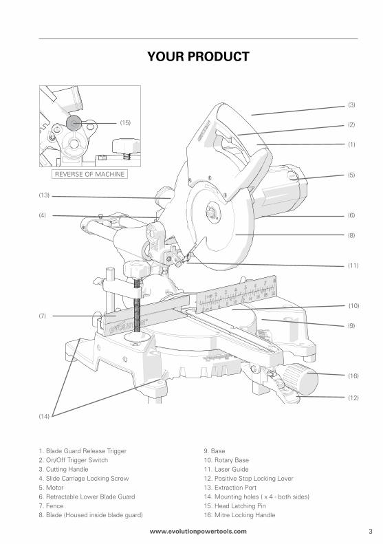
1. Blade Guard Release Trigger2. On/Off Trigger Switch3. Cutting Handle 4. Slide Carriage Locking Screw5. Motor6. Retractable Lower Blade Guard 7. Fence8. Blade (Housed inside blade guard)
9. Base10. Rotary Base11. Laser Guide12. Positive Stop Locking Lever13. Extraction Port14. Mounting holes ( x 4 - both sides)15. Head Latching Pin16. Mitre Locking Handle
3www.evolutionpowertools.com
Your produCT
(1)
(4)
(13)
(7)
(3)
(2)
(5)
(9)
(6)
(8)
(11)
(10)
(16)
(12)
(14)
REVERSE OF MACHINE
(15)

44 www.evolutionpowertools.com
6mm Hex Key (Blade Change)
TooLS NEEdEd For ASSEMBLY & AdJuSTMENTS
Flat Bladed Screwdriver
SUPPLIED NOT SUPPLIED

55www.evolutionpowertools.com
download a free Qr reader app and scan the Qr CodE (above).
Instantly watch the HD Assembly Video on your Smart Phone. Make sure the HD setting is on.
QR Code
WATCh ANd LEArN
®
You can also view the hd Assembly Video online located in the ‘Instructions’ section at:
http://www.evolutionpowertools.co.uk/videos/setups/flatpackmitresaw.html

66 www.evolutionpowertools.com
FLATpACK ASSEMBLY GuIdE
Flat Packed Mitre Saws Assembly Instructions
Your Mitre Saw is supplied as 3 major component parts which need assembling.
The assembly process is a ‘one time assembly’.
Once assembly is successfully completed no attempt to disassemble the machine should be made. The blade and some other smaller parts also need to be fitted by the operator. A safety check must be carried out once assembly is completed and before the machine is used.
The Cutting Head is supplied with an approved power cable and plug fitted for its intended country of use.
do not under any circumstances plug the Cutting head into the power supply and try to use it as a hand held circular saw.
WArNING: Do not connect this machine to the mains power supply until assembly has been completed and a complete safety check carried out.
77www.evolutionpowertools.com
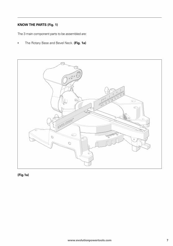
KNoW ThE pArTS (Fig. 1)
The 3 main component parts to be assembled are:
• The Rotary Base and Bevel Neck. (Fig. 1a)
(Fig.1a)
88 www.evolutionpowertools.com
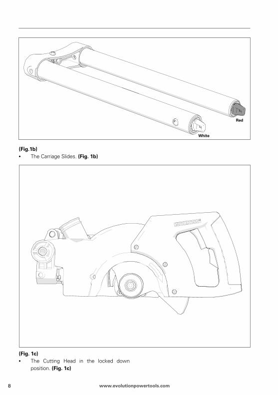
(Fig.1b)• The Carriage Slides. (Fig. 1b)
(Fig. 1c)• The Cutting Head in the locked down
position. (Fig. 1c)
red
White

99www.evolutionpowertools.com
Also to be fitted are:
• The Mitre Locking Handle. (Fig. 2a)• The Positive Stop Locking Lever. (Fig. 2b)• The Slide locking Screw and antivibration
spring (Fig. 2c)• The Blade. (Fig. 2d)
Note: One of two types of Mitre Locking Handle will be supplied, according to the machine purchased. Only the short spigot handle requires the spacer.
(Fig. 2a) Fit the spacer over threaded spigot before installation. (Short spigot handled machines only)
(Fig. 2b)
(Fig. 2c)
(Fig. 2d)
WArNING: The blade is the last part to be fitted. It must only be fitted after the assembly process is completed and the mitre saw has passed the Assembly Safety Checks.
SpIGoT SpIGoT
SpACEr
Short Spigot handle Long Spigot handle
ANTI-VIBrATIoN SprING

1010 www.evolutionpowertools.com
ASSEMBLY proCEdurE
read these instructions carefully.
Carefully remove all of the parts from the packaging and check that all parts are present and correct.
• Identify the parts and note that some of the main parts are colour coded to aid assembly.
• Select the Carriage Slide and Rotary Base and Bevel Neck.
Fitting the positive Lock Lever
The Positive Lock Lever pushes onto the lever mechanism found just below the Mitre Locking Handle (Fig 3a)
(Fig. 3a)
Fitting the Mitre Locking handle
The threaded rod of the Mitre Locking Handle slides into a tunnel, or screws into a boss (according to type of machine purchased) located just above the Positive Stop Locking Lever.
• Carefully insert the Mitre Locking Handle fully into the Rotary Table Extension.
• Turn the Locking Handle clockwise to engage and draw the Handle into the locking mechanism. (Fig. 3b)
• Tighten the Locking Handle securely to lock the Rotary Table.
(Fig. 3b)
ITEMS SuppLIEd
BLAdE pACKAGING SuMMArY INSTruCTIoNS
INSTruCToN MANuAL (Assembly)
INSTruCToN MANuAL (operations)
roTArY BASE ANd NECK
CuTTING hEAd (with Moulded plug)
CArrIAGE SLIdES (colour coded)
BLAdE
MITrE LoCKING hANdLE
poSITIVE STop LoCKING LEVEr
hoLd doWN CLAMp
hEX KEYS(s) (assembly and blade change)
MArKET SpECIFIC ACCESSorIES(not supplied as standard in all markets. Available as a customer cost optional accessory. See operation manual for full application details)
BLANKING pLuG(to blank extraction port when cutting Steel)
AdApTor TuBE(for connecting extraction port to commercial extraction equipment)
LENS CAp (for laser protection)
positive Lock Lever
Mitre Locking handle

1111www.evolutionpowertools.com
Adjusting the Bevel Neck to 00
The Bevel Neck is supplied fitted to the rotary base and tilted at a 450 angle to the left. Before the carriage slides are inserted into the Bevel Neck, the Bevel Neck must be adjusted to the vertical position (00)
• Slacken the Bevel Locking screw, using the Bevel locking Handle. (Fig. 4)
• Rotate the Bevel Neck to the vertical position so that it is against the 00 stop.
• Tighten the Bevel Locking screw.
(Fig. 4)
(Fig. 5)
Inserting the Carriage Slide
The Carriage Slides two arms should be inserted into the two linear bearings in the Bevel Neck. From the BACK of the machine the red lug should be to the left and the white lug should be to the right. (Fig. 5)
To aid correct assembly note that the individual arms of the slide are colour coded, red for the Right Hand arm (as seen from the FroNT of the machine) and white for the Left Hand arm. The linear bearings are likewise colour coded.
WArNING: Read steps associated with Figs 4, 5, 6 and 7 before proceeding.
For accuracy of assembly the two (2) arms of the Carriage Slide are not the same diameter. Each arm has a dedicated linear bearing in the Bevel Neck.
FroNT Viewing
BACK Viewing

1212 www.evolutionpowertools.com
Ensure that the Carriage Slide is inserted into the Bevel Neck the correct way round with the cable clip attachment position on the back support bracket pointing upwards. (Fig. 6)
(Fig. 6)
(Fig. 7)
• Slide the Sliding Carriage arms through the Bevel Neck for approximately half of their length.
• Insert the slide Locking Screw into the threaded hole in the Bevel Neck, ensuring that the antivibration spring is fitted underneath the hand knob.
• Lock them into position using the Sliding Carriage Locking Screw. (Fig. 7)
Note: If for any reason (transit damage, unpacking error, operator mistake etc) the locating lugs have been tripped (Fig. 8) the Sliding Carriage cannot be fitted into the Bevel Neck or onto the Cutting Head until they are reset.
Sliding Carriage Locking Screw
red
White
1313www.evolutionpowertools.com
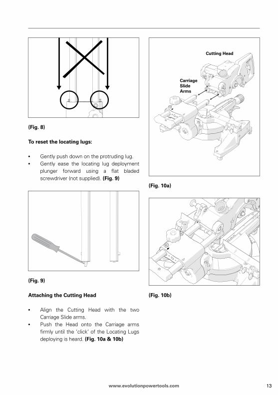
(Fig. 8)
To reset the locating lugs:
• Gently push down on the protruding lug.• Gently ease the locating lug deployment
plunger forward using a flat bladed screwdriver (not supplied). (Fig. 9)
(Fig. 9)
Attaching the Cutting head
• Align the Cutting Head with the two Carriage Slide arms.
• Push the Head onto the Carriage arms firmly until the ‘click’ of the Locating Lugs deploying is heard. (Fig. 10a & 10b)
(Fig. 10a)
(Fig. 10b)
Cutting head
Carriage Slide Arms
1414 www.evolutionpowertools.com
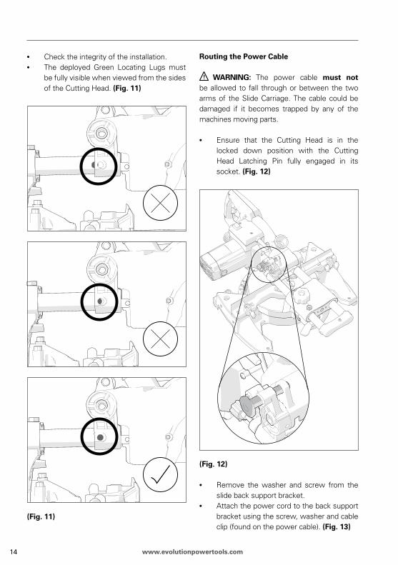
• Check the integrity of the installation.• The deployed Green Locating Lugs must
be fully visible when viewed from the sides of the Cutting Head. (Fig. 11)
(Fig. 11)
routing the power Cable
WArNING: The power cable must not be allowed to fall through or between the two arms of the Slide Carriage. The cable could be damaged if it becomes trapped by any of the machines moving parts.
• Ensure that the Cutting Head is in the locked down position with the Cutting Head Latching Pin fully engaged in its socket. (Fig. 12)
(Fig. 12)
• Remove the washer and screw from the slide back support bracket.
• Attach the power cord to the back support bracket using the screw, washer and cable clip (found on the power cable). (Fig. 13)

1515www.evolutionpowertools.com
(Fig. 13)
• The power cable must not be stretched or taut between the Cutting Head and the attached rear cable clip.
• Deflection at the midpoint of the cable should be 50-60mm. (Fig. 14) This will give sufficient ‘slack’ in the cable to allow the Cutting Head to rise and lower and still retain correct and safe cable routing.
WArNING: The power cable must not be allowed to fall through or between the two arms of the Slide Carriage. The cable could be damaged if it becomes trapped by any of the machines moving parts.
(Fig. 14)
Fitting the Blade
WArNING: Only carry out this operation with the machine disconnected from the mains supply.
WArNING: Only fit the blade after the assembly process and the Assembly Safety Checks are completed.
Note: It is recommended that the operator wears protective gloves when handling the blade during installation or when changing the machines blade.
1616 www.evolutionpowertools.com
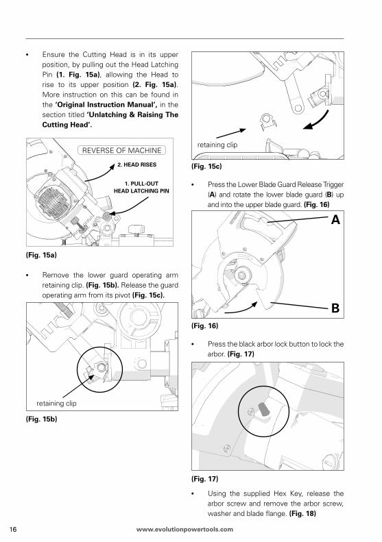
• Ensure the Cutting Head is in its upper position, by pulling out the Head Latching Pin (1. Fig. 15a), allowing the Head to rise to its upper position (2. Fig. 15a). More instruction on this can be found in the ‘original Instruction Manual’, in the section titled ‘unlatching & raising The Cutting head’.
(Fig. 15a)
• Remove the lower guard operating arm retaining clip. (Fig. 15b). Release the guard operating arm from its pivot (Fig. 15c).
(Fig. 15b)
(Fig. 15c)
• Press the Lower Blade Guard Release Trigger (A) and rotate the lower blade guard (B) up and into the upper blade guard. (Fig. 16)
(Fig. 16)
• Press the black arbor lock button to lock the arbor. (Fig. 17)
(Fig. 17)
• Using the supplied Hex Key, release the arbor screw and remove the arbor screw, washer and blade flange. (Fig. 18)
retaining clip
REVERSE OF MACHINE
1. puLL-ouT hEAd LATChING pIN
2. hEAd rISES
retaining clip
1717www.evolutionpowertools.com
1
2 3 4
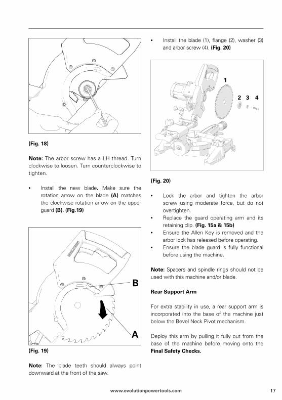
(Fig. 18)
Note: The arbor screw has a LH thread. Turn clockwise to loosen. Turn counterclockwise to tighten.
• Install the new blade. Make sure the rotation arrow on the blade (A) matches the clockwise rotation arrow on the upper guard (B). (Fig.19)
(Fig. 19)
Note: The blade teeth should always point downward at the front of the saw.
• Install the blade (1), flange (2), washer (3) and arbor screw (4). (Fig. 20)
(Fig. 20)
• Lock the arbor and tighten the arbor screw using moderate force, but do not overtighten.
• Replace the guard operating arm and its retaining clip. (Fig. 15a & 15b)
• Ensure the Allen Key is removed and the arbor lock has released before operating.
• Ensure the blade guard is fully functional before using the machine.
Note: Spacers and spindle rings should not be used with this machine and/or blade.
rear Support Arm
For extra stability in use, a rear support arm is incorporated into the base of the machine just below the Bevel Neck Pivot mechanism.
Deploy this arm by pulling it fully out from the base of the machine before moving onto the Final Safety Checks.
1818 www.evolutionpowertools.com
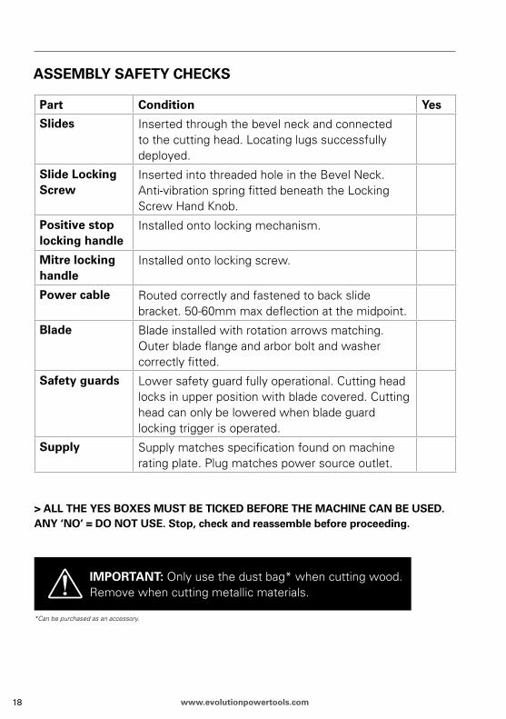
ASSEMBLY SAFETY ChECKS
part Condition Yes
Slides Inserted through the bevel neck and connected to the cutting head. Locating lugs successfully deployed.
Slide Locking Screw
Inserted into threaded hole in the Bevel Neck. Anti-vibration spring fitted beneath the Locking Screw Hand Knob.
positive stop locking handle
Installed onto locking mechanism.
Mitre locking handle
Installed onto locking screw.
power cable Routed correctly and fastened to back slide bracket. 50-60mm max deflection at the midpoint.
Blade Blade installed with rotation arrows matching. Outer blade flange and arbor bolt and washer correctly fitted.
Safety guards Lower safety guard fully operational. Cutting head locks in upper position with blade covered. Cutting head can only be lowered when blade guard locking trigger is operated.
Supply Supply matches specification found on machine rating plate. Plug matches power source outlet.
> ALL ThE YES BoXES MuST BE TICKEd BEForE ThE MAChINE CAN BE uSEd. ANY ‘No’ = do NoT uSE. Stop, check and reassemble before proceeding.
IMporTANT: Only use the dust bag* when cutting wood.Remove when cutting metallic materials.
*Can be purchased as an accessory.

1919www.evolutionpowertools.com
FINAL SAFETY ChECKS
part Condition Yes
Blade Blade installed with the rotation arrows on the blade matching the rotation arrows on the upper blade guard. Outer blade flange and arbor bolt and washer correctly fitted.
Assembly Repeat the Assembly Safety Checks.
operation With the machine switched OFF and disconnected from the mains supply carry out the following:When all adjustments have been made, set the machine at each of the maximum settings.Lower the blade to its lowest position and rotate the blade by hand, (it is advisable to wear gloves whilst doing this), and ensure that the blade does not foul on any part of the machine, castings or guards.
> ALL ThE YES BoXES MuST BE TICKEd BEForE ThE MAChINE CAN BE uSEd. ANY ‘No’ = do NoT uSE. Stop, check and reassemble before proceeding.

uK hQ
Evolution power Tools, Venture One, Longacre Close, Holbrook Industrial Estate, Sheffield, S20 3FR, UK
TEL: +44 (0) 114 251 1022FAX: +44 (0) 114 247 3339
FrANCE hQ
Evolution power Tools,61 Avenue Lafontaine, 33560,Carbon-Blanc, France
TÉL: + 33 (0)5 57 30 61 89FAX: + 33 (0)5 57 30 61 94
uSA hQ
Evolution power Tools LLC,8363 Research Drive, Davenport,Iowa 52806U.S.A
TEL: (Toll Free) 866-EVO-TOOLFAX: 563.386.8010
®


![UM - Original [Heated bed Assembly Manual] v1.0 (1).indd](https://static.fdocuments.net/doc/165x107/5878a0841a28ab2d3c8bbe3a/um-original-heated-bed-assembly-manual-v10-1indd.jpg)